robot hand design - kth.se · by working structured and purposeful a fully functioning second...
TRANSCRIPT

ROBOT HAND DESIGN -PALM IMPROVEMENT AND A ROBOTIC
HAND-ARM INTERFACE
Thesis work
of
Klaus Schmidt
2008-03-06
Supervisors : MSc. Johan Tegin, KTH Machine Design, Mechatronics Lab.
MSc. Pieter Grebner, KTH Syd Campus Telge


I
Examensarbete MMK 2008:x {avdnr}
ROBOT HAND DESIGN -PALM IMPROVEMENT AND A ROBOTIC
HAND-ARM INTERFACE
Klaus Schmidt
Godkänt
2008-03-
Examinator
Pieter Grebner
Handledare
Johan Tegin
Uppdragsgivare
KTH Machine Design
Kontaktperson
Johan Tegin
ABSTRACT The following thesis work was written in connection with a project at the KTH Machine
Design Department. The main project task was to develop a cost-effective robotic three finger
hand. The tasks within this thesis work was to further develop a existing robot hand prototype
despite it’s god characteristics and to develop a hand – arm interface to the ABB robot arm.
During the course of the project, several hand concepts were evaluated. Their shape and
assembly properties were evaluated. The questions how the actuators should be placed and
how the interface could be included into the prototype were also important. The final hand
prototype has four degrees of actuation and 10 degrees of freedom. It can be force, position
and velocity controlled thanks to a few sensors and encoders. This small amount of sensors
and encoders is possible through the under actuated design of the hand.
The second prototype was first and foremost improved regarding the shape and the assembly
properties, thus the hand becomes also a bit stronger and the thumb position has been
adjusted. The hand can perform eight different grasps and can be position and force
controlled.

II

III
SAMMANFATTNING Följade examensarbetet skrevs i samband med ett projekt vid KTH: s maskinteknikavdelning.
Huvuduppgiften var att utveckla en kostnadseffektiv trefingerrobothand. Uppgiften inom
detta examensarbete var vidareutveckla den existerande prototypen, trots dess goda
egenskaper och att utveckla ett handarm gränssnitt till en ABB-robotarm.
Under projektets gång utvärderades flera koncept. De blev utvärderade angående deras
utformning och monteringsegenskaper. Frågorna hur motorerna kunde placeras och hur
gränssnittet skulle utformas var även viktiga. Den slutgiltiga prototypen har tio frihetsgrader
och fyra motorer. Den är kraft-, positions- och hastighetsstyrd av några sensorer och enkodrer.
Fåtalet sensorer och enkodrar är möjligt på grund av designen med endast fyra motorer och
tio frihetsgrader.
Den andra prototypen förbättrades först och främst med hänsyn till dess utformning och
monteringsegenskaper. Handen har även blivit lite starkare och tummens position har
anpassats. Robothanden kan utföra åtta olika grepp och kan vara kraft- och positionsstyrd.

IV

V
ACKNOWLEDGEMENT To begin with I want to thank Johan Tegin for his support and advice during the execution of
this thesis work and the out carried project. With his fair comments and opinions he
contributed to the success of the following thesis work. I also want to thank Magnus
Birgestam for all the rewarding discussions and the good cooperation during the project and
Satoshi Yoneyama for translating the motor data sheet from Japanese into English. Last but
not least, I want to thank my family and Lisa for their understanding and moral support.

VI
NOTATION Some terms mentioned frequently regarding the hand and the robot finger are previously
explained in the following section. The terms regarding the finger and the finger joints are
taken directly from the previous project’s report [5].
The directions will in this report be called:
distal direction the direction towards the finger tip
proximal direction the direction towards the palm
The links will be called:
base phalanx the one included into the hand
Proximal phalanx the one next to the base phalanx in distal direction
the middle phalanx the one between the distal an the proximal phalanx
distal phalanx the most distal one
The joints are termed as the corresponding joints in the human hand anatomy.
The one between base phalanx and proximal phalanx is the metacarpophalangeal joint (MP)
The next one the proximal interphalangeal (PIP)
The one between the middle phalanx and the distal phalanx is the distal interphalangeal joint
(DIP)
The plates on the sides of the links are called side plates(figure N1).
The plates which are screwed on the top of the links to fix the spring are called screw plates
The term degree of freedom will be called in short DOF.
The term degree of actuation will be called in short DOA.
The housing for actuators and encoders will be called for hand backside.
The part of the thumb which is fixed in the hand backside will be called thumb base.
Figure N1 The finger links and screw plates.

VII
Table of Contents ABSTRACT................................................................................................................................I
SAMMANFATTNING............................................................................................................ III
ACKNOWLEDGEMENT .......................................................................................................VI
NOTATION .............................................................................................................................. V
1. INTRODUCTION..............................................................................................................- 1 - 1.1 MOTIVATION.......................................................................................................................................- 1 - 1.2 THE PROJECT......................................................................................................................................- 1 - 1.3 GOAL......................................................................................................................................................- 2 -
2. STATE OF ART ................................................................................................................- 3 - 2.1 THE HUMAN HAND ............................................................................................................................- 3 - 2.2 THE IRON HAND OF THE REICHSRITTER GÖTZ GOTTFREID VON BERLICHINGEN...- 4 - 2.3 THE SHADOW HAND..........................................................................................................................- 4 - 2.4 THE BH8-SERIES BARRETT HAND ................................................................................................- 5 - 2.5 THE DLR HAND II ...............................................................................................................................- 6 -
3. SPECIFICATION ..............................................................................................................- 7 - 3.1 TASK SPECIFICATION ......................................................................................................................- 7 - 3.2 DESIGN SPECIFICATIONS................................................................................................................- 8 - 3.3 PERFORMANCE SPECIFICATIONS................................................................................................- 8 -
4. PREVIOUS WORK ...........................................................................................................- 9 - 4.1 THE FINGER.........................................................................................................................................- 9 -
4.1.1 DESIGN............................................................................................................................................- 9 - 4.1.2 FUNCTION ....................................................................................................................................- 10 - 4.1.3 MATERIALS ...................................................................................................................................- 11 - 4.1.4 MANUFACTURING.......................................................................................................................- 11 -
4.2 THE PALM...........................................................................................................................................- 12 - 4.2.1 CONSTRUCTION...........................................................................................................................- 12 - 4.2.2 THE THUMB JOINT......................................................................................................................- 13 - 4.2.3 FUNCTION ....................................................................................................................................- 13 -
5. THE ABB ROBOT ARM ................................................................................................- 14 -
6. ACTUATORS SENSORS AND ENCODERS................................................................- 15 - 6.1 THE MOTORS.....................................................................................................................................- 15 - 6.2 THE SERVO.........................................................................................................................................- 15 - 6.3 THE OPTICAL ENCODER EE-SX1108...........................................................................................- 16 -
6.3.1 FUNCTION ....................................................................................................................................- 16 - 6.3.2 DIMENSION AND ASSEMBLE PROPETIES................................................................................- 16 -
6.4 THE ABSOLUTE ENCODER............................................................................................................- 17 -
VIII
6.5 THE FSR SENSORS............................................................................................................................- 18 - 7. DESIGN CONCEPTS......................................................................................................- 19 -
7.1 CHOICE OF MATERIAL ..................................................................................................................- 19 - 7.2 DIFFERENT SHAPES AND INTERFACES ....................................................................................- 20 - 7.3 PLACEMENT OF THE ACTUATORS.............................................................................................- 22 - 7.4 PLACEMENT OF THE ACTUATORS AROUND THE THUMB JOINT....................................- 24 -
8. MOTORSYSTEM............................................................................................................- 25 -
9. THE FINALDESIGN OF THE HAND ...........................................................................- 26 - 9.1 THE THUMBJOINT ...........................................................................................................................- 26 -
9.1.1 FUNCTION AND SHAPE ..............................................................................................................- 27 - 9.1.2 GUIDING THE TENDON..............................................................................................................- 27 - 9.1.3 THE THUMBJOINTBEARINGS ....................................................................................................- 28 - 9.1.4 THUMBJOINTASSEMBLY ............................................................................................................- 28 -
9.2 PALMDESIGN.....................................................................................................................................- 29 - 9.3 DESIGNING THE BACK OF THE HAND.......................................................................................- 29 - 9.4 DESIGNING THE ROBOTARM INTERFACE ..............................................................................- 31 - 9.5 THE SHAPE AND DIMENSIONS OF THE HAND ........................................................................- 33 -
9.6 BEHAVIOR OF THE HAND UNDER LOAD..................................................................................- 35 - 10. EVALUATION OF THE PROTOTYPE.......................................................................- 35 -
10.1 THE PROTOTYPE PARTS..............................................................................................................- 35 - 10.1.1 THE HAND BACKSIDE...............................................................................................................- 35 - 10.1.2 THE PALM ...................................................................................................................................- 36 - 10.1.3 THE THUMB BASE......................................................................................................................- 36 - 10.1.4 THE THUMB BEARING BLOCKS ..............................................................................................- 36 - 10.1.5 THE FINGERS .............................................................................................................................- 37 - 10.1.6 THE BALL BEARINGS AND THE TENDONGUIDE ..................................................................- 38 - 10.1.8 THE PULLEY ...............................................................................................................................- 38 -
10.2 TESTING THE PROTOTYPE.........................................................................................................- 39 - 10.2.1 POSSIBLE GRASPS .....................................................................................................................- 39 - 10.2.2 FINGERVELOCITIES AND THEIR BEHAVIOR UNDER LOAD ...............................................- 40 -
10.3 BENCHMARKING THE HAND ..................................................................................................... - 42 - 10.3.1 THE BREAKFUNKTION OF THE MOTOR AND POWER CONSUMTION OF THE HAND....- 42 - 10.3.2 BACKLASH ..................................................................................................................................- 44 - 10.3.3 PLAY.............................................................................................................................................- 44 - 10.3.4 FATIGUE .....................................................................................................................................- 44 -
11. CHARACTERISICS......................................................................................................- 45 - 11.1 TASK CHARACTERISTICS ...........................................................................................................- 45 - 11.2 DESIGN CHARACTERISICS..........................................................................................................- 46 - 11.3 PERFORMANCE CHARACTERISICS .........................................................................................- 47 -
12. LESSONS LEARNED...................................................................................................- 48 -
IX
13. CONCLUSION ..............................................................................................................- 49 -
BIBLIOGRAPHY ........................................................................................................................
APPENDIX 1: DRAWINGS .......................................................................................................
APPENDIX 2 : FEM-ANALYSES..............................................................................................
APPENDIX 3: FORCES IN THE THUMBJOINT .....................................................................
APPENDIX 4: BOM....................................................................................................................
APPENDIX 5: RISK ANALYSES..............................................................................................
APPENDIX 6: ASSEMBLE THE HAND...................................................................................
APPENDIX 7: DURAFORM DATA SHEET.............................................................................
APPENDIX 8: DATASHEET STL JAPAN MOTOR ................................................................

- 1 -
1. INTRODUCTION In this chapter, the purpose, the background and the circumstances of this project will be
described. It will also be mentioned why it is important to develop cost-efficient robot hands
and what was important to achieve within this project.
1.1 MOTIVATION In today’s society robots are used in different areas and applications like in industries and
medicine. Especially robot end effectors are of particular interest because they perform the
work the robots are designed for, they make it possible to grasp objects or to work up
material. Service robotics are another important research. Especially healths care where
people who lost a hand or arm can use a robotic grasper to make their everyday life easier.
Nowadays the most functional graspers which are available for an affordable cost are having
also a low cost design. So because of esthetic reasons people often prefer artificial limbs
which have a lower function or no function at all but are looking more humanlike. Yet also in
industries a grasper which can perform many different work tasks at a cheap price can be an
improvement. So it is important to develop a cheap robotic grasper which can perform
everyday grasps. The most hands developed in university research projects are mounted with
many actuators and sensors and are for this reason inappropriate for manufacturing in big
series and to expensive for the average user.
1.2 THE PROJECT This thesis work was executed at the KTH Mechatronics Lab in Stockholm Sweden. The task
was to develop a second prototype of an existing robot hand, despite of the god characteristics
of the existing prototype. The focus of this thesis within the project lied on to improve the
shape, function and assembly properties of the robotic hand. In addition to that a modular
electromechanical interface to the Abb robot arm should be developed. Simultaneously a
project developing the control interface of the hand was done by Magnus Birgestam. More
information about that project can be found in the project report [1]. To reduce the cost of the
hand, the old hand is designed under actuated and simple with four DOA and ten DOF. To
keep the manufacturing costs down is also an important issue developing the new Prototype.
Several different concepts where analyzed before the final Prototype was built. To design the
hand Solid Edge© was used. FEM analyses where done in Pro Mechanica. Rendering was
done in Flamingo for Rhino.

- 2 -
1.3 GOAL By working structured and purposeful a fully functioning second prototype of a three finger
robot hand and a modular interface to the Abb robot arm should be developed and
manufactured. The defined project goals can be found the specification chapter (page 7).

- 3 -
2. STATE OF ART This chapter describes the human hand, one historical artificial hand and three robotic
graspers. First imitations of the human hand are coming from the prosthetic and in the last
few years many robotic hands had be developed around institutes all over the world. This
chapter shows and describes three different robotic graspers. One industrial robotic grasper
(the Barrett hand), one humanoid robot hand without a wrist (The Shadow dexterous hand)
and one humanoid robot hand including a wrist (The DLR Hand II).
2.1 THE HUMAN HAND Developed under many years of evolution the human hand has made us to what we are today.
The human hand is composed by 27 different bones and the opposing thumb is characteristic
for the human. The opposing thumb enables the precision grasp between the long finger and
the thump (grasp 9 in the Cutkosky grasping hierarchy [2]) which enables us to write or to
perform precision work. Further the hand has 20 DOF and the most muscles are placed in the
forearm and transmit their developed force via tendons to the fingers. The bigger muscles in
the hand are the thenar muscle on the thumb side and the Hypothenar muscle on the side of
the little finger [9].
Figure 2. 1 The human hand[9].

- 4 -
2.2 THE IRON HAND OF THE REICHSRITTER GÖTZ GOTTFREID
VON BERLICHINGEN First imitations of human hands come from the prosthetic, as for example the iron fist of the
Götz of Berlichingen (1480-1562). That hand had five separate fingers, which could be bent
passively and could be redeemed by pushing a button. The hand had a mass of 1.5 kg what
wasn’t to bad for that time.
Figure 2.2 The iron hand.
2.3 THE SHADOW HAND The Shadow Dextrous Hand is an advanced humanoid robot hand. The hand can perform 24
different grasps and is as close as it gets to a human hand. The hand has a total mass of 3.9 kg
including all sensors and actuators. It’s built from a plenty different materials; the forearm
bone is made of steel, the palm is made of acetyl, aluminum and polycarbonate and the
fingers are made of acetyl. The hand is driven by 40 air muscles (40 degrees of actuation)
which are mounted one the forearm. These are connected with tendons too the joints. The air
muscle technology requires both electric current and compressed air. The hand is equipped
with tactile sensors at the finger tips for feedback control. Each sensor has an output range
from zero up to one kg.
Figure 2. 3 The Shadow hand.
- 5 -
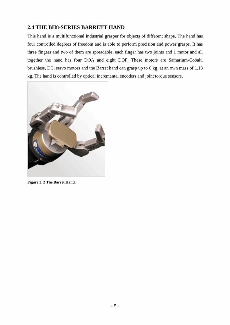
2.4 THE BH8-SERIES BARRETT HAND This hand is a multifunctional industrial grasper for objects of different shape. The hand has
four controlled degrees of freedom and is able to perform precision and power grasps. It has
three fingers and two of them are spreadable, each finger has two joints and 1 motor and all
together the hand has four DOA and eight DOF. These motors are Samarium-Cobalt,
brushless, DC, servo motors and the Barret hand can grasp up to 6 kg at an own mass of 1.18
kg. The hand is controlled by optical incremental encoders and joint torque sensors.
Figure 2. 2 The Barret Hand.

- 6 -
2.5 THE DLR HAND II
This Hand is a further development of the DLR I Hand. In this further developed version the
focus was to improve autonomous grasping. The fine manipulation possibilities where
reached by using fully integrated actuators and electronics. The DLR Hands are as the hand in
the KTH Mechatronic Lab just hands without a forearm. Hands with a integrated forearm
open up for much better design opportunities (anthropomorphic design) because the
additional space in the forearm can be used for placing actuators and electronic components.
One disadvantage of hands with integrated forearms is that they can’t be placed on robot
arms.
The DLR II hand has an open skeleton design which enables better maintenance and also the
testing of different grasp surfaces without redesigning finger parts. When power grasps are
performed it is important that all fingers are parallel but when precision grasps are performed
it is necessary to have large regions of intersection of the ranges of motion. Furthermore, it is
important that the thumb and the ring finger are placed opposite to each other. To perform
these different assignments the hand has 16 DOF and 12 DOA.
The actuators are placed in each finger joint. The base joint requires a bevel gear which is
directly coupled to the motors to enable the two DOF. The hand is equipped with sensors for
torque, position, speed and temperature control. The control of the fingers and the hand is
done by an external computer.
Figure 2. 3 One finger of the DLR Hand Figure 2. 4 The DLR Hand with a filled bottle

- 7 -
3. SPECIFICATION The task specification is taken from previous projects because it hasn’t changed and is still of
current interest. The design specification was written within this project because it was of
certain interest to improve the shape and the assembly properties of the hand
3.1 TASK SPECIFICATION
• The hand shall be able to grasp and to lift a filled bottle with the total mass of 2 kg,
regardless of the height the bottle is grasped. It shall be possible to rotate the bottle at
180˚ C. That means the hand has to perform grasp 1 in the Cutkosky grasping
hierarchy [6].
• The same shall be possible with a card box with a total weight of 1 kg (also grasp 1).
• The hand shall be able to grasp and to pick up a chocolate bar with one and two
forefingers and the thumb (grasp 8 and 9 in the grasping hierarchy).
• The hand shall also be able to hold a credit card between one forefinger and the thumb
(grasp 9 in the grasping hierarchy).
• The hand shall be able to press a button.

- 8 -
3.2 DESIGN SPECIFICATIONS
• The palm shall be redesigned and a modular interface to the ABB robot arm shall be
constructed.
• The palm shall house all actuators, tendons and cables.
• The dimensions and the shape of the palm (hand) shall be close to a human hand.
• The electrical interface of the hand shall be composed of less than two industrial
standard connectors.
• The palm shall be prepared for the installation of a tactile sensor.
• The hand shall become easier to assemble than the current (2007-08-11) [6].
• A solution to center the thumb axis to the servo axis has to be found.
• The thumb position has to be adjusted.
• Cable routing for all cables has to exist.
• The three distal links of the fingers shall remain the same.
3.3 PERFORMANCE SPECIFICATIONS
• The mass of the hand shall be less than 300 g.
• The amount of parts in the thumb joint shall be reduced at least by 50 %.
• The hand shall cost less than 200 € to manufacture.

- 9 -
4. PREVIOUS WORK
4.1 THE FINGER In the previous project the finger was developed to its final shape. This chapter describes its
function in a short way. More profound information can be found in the previous project
reports [5] and [6].
4.1.1 DESIGN
The finger is made in a lightweight construction and contains four parts, the Base Phalanx, the
Proximal Phalanx, the Middle Phalanx and the Distal Phalanx. Besides these parts there are
some other parts needed to put the finger together, a spring to unbend the finger, four screw
plates and four screws to fasten the spring and to keep the finger together. For force feedback
control there are three FSR-sensors mounted on the three outermost phalanges these are
covered with rubber foam to spread the applied force even on the fingertips.
Figure 4. 1 The bas phalanx Figure 4. 2 The proximal.
phalanx.
Figure 4. 3 the middle phalanx. Figure 4. 4The distal phalanx.

- 10 -
4.1.2 FUNCTION
By applying a force at the tendon which runs trough the hole at the inside of the finger the
finger is being bent to grasp an object. When this force is taken away the finger is unbent by
the spring fixed at the backside. The spring has two functions, to hold the joints together and
to unbend the finger. One the finger parts Fsr´s are mounted to implement forcesensing. For
force sensing it is important to have a limited area in the same size as the active area of the
force sensor but against the grasped object the area should be as big as the surface of the
finger part. The Force Sensors are covered by the rubber foam in a certain way to divide the
applied force even. This is because there are problems with grasping of objects of a certain
shape or and sharp edges. More information about force sensing can be found in the previous
project report [7].
Figure 4. 5 The assembled finger.

- 11 -
4.1.3 MATERIALS
The finger parts are made of Full Cure [6] and have a tensile strength of 42 MPa. This is an
appropriate tensile strength to get a light design and to get done with the applied forces. The
screw plates are made of Plexiglas and the spring is Steel from SAAB and has a tensile
strength of 1 770 MPa and a Modules of elasticity of 220 000 MPa. These material properties
of the steel are important because they are reducing the plastic deformation and are keeping
the finger stretched by counteracting gravity. The screws are titan screws to reduce the
weight of the finger. This is important to keep the influence of gravity on the fingertip as
small as possible. The Tendon is a fishing line from Zalt and has a diameter of 0,35 mm.
Figure 4. 6 All parts of the finger.
4.1.4 MANUFACTURING
The finger parts are manufactured by rapid prototyping .The screw plates and the springs are
manufactured in the KTH Machine Design workshop.

- 12 -
4.2 THE PALM In previous projects a hand prototype was developed. The Prototype was put together under
much time pressure but is in spite of some miner difficulties fully functionally. This chapter
will describe the existing prototype in a short way, more g information can be found in the
previous reports [5] and [6].
4.2.1 CONSTRUCTION
The Hand has two fingers and one thumb. To keep the construction light these are hold
together by an aluminum palm. The fingers the thumb and all actuators and sensors are
fastened with screws on the palm. The hand is driven by three DC motors and one Servo
(more information in chapter 6). The DC motors are from the company STL Japan and are
driven by 5V. The motors are to a certain degree protected by the aluminum sheet which is
palm and hand backside at once. The two encoders, all cables and the servo are lying open at
the inside.
Figure 4. 7 The first hand prototype.

- 13 -
4.2.2 THE THUMB JOINT
The thumb is placed opposite and in the middle of the two fingers. This position was taken
because it enables a nearly humanlike movement and it keeps the torques small [6]. The Servo
is placed behind the thumb and makes the rotary movement of 90˚ C around the thumb axis
possible. The motor which is placed under the Base Phalanx of the thumb rotates with the
thumb and bends the thumb.
Figure 4. 8 The thumb joint.
4.2.3 FUNCTION
The DC motors perform the bending movement of the fingers and the thumb. This by rolling
up the tendon (fishing line) that comes from the fingers, on a pulley placed on the outgoing
axis of the gearbox. The servo performs the rotary movement of the thumb. In the previous
project all grasps mentioned in Cutkosky grasping hierarchy where tested and six different
grasps could be performed with the hand, for example the large diameter power grasp and the
thumb – two fingers precision grasp (se figure 4.9).
Figure 4. 9 The thumb two finger precision grasp (picture Jakob Reiche).
- 14 -
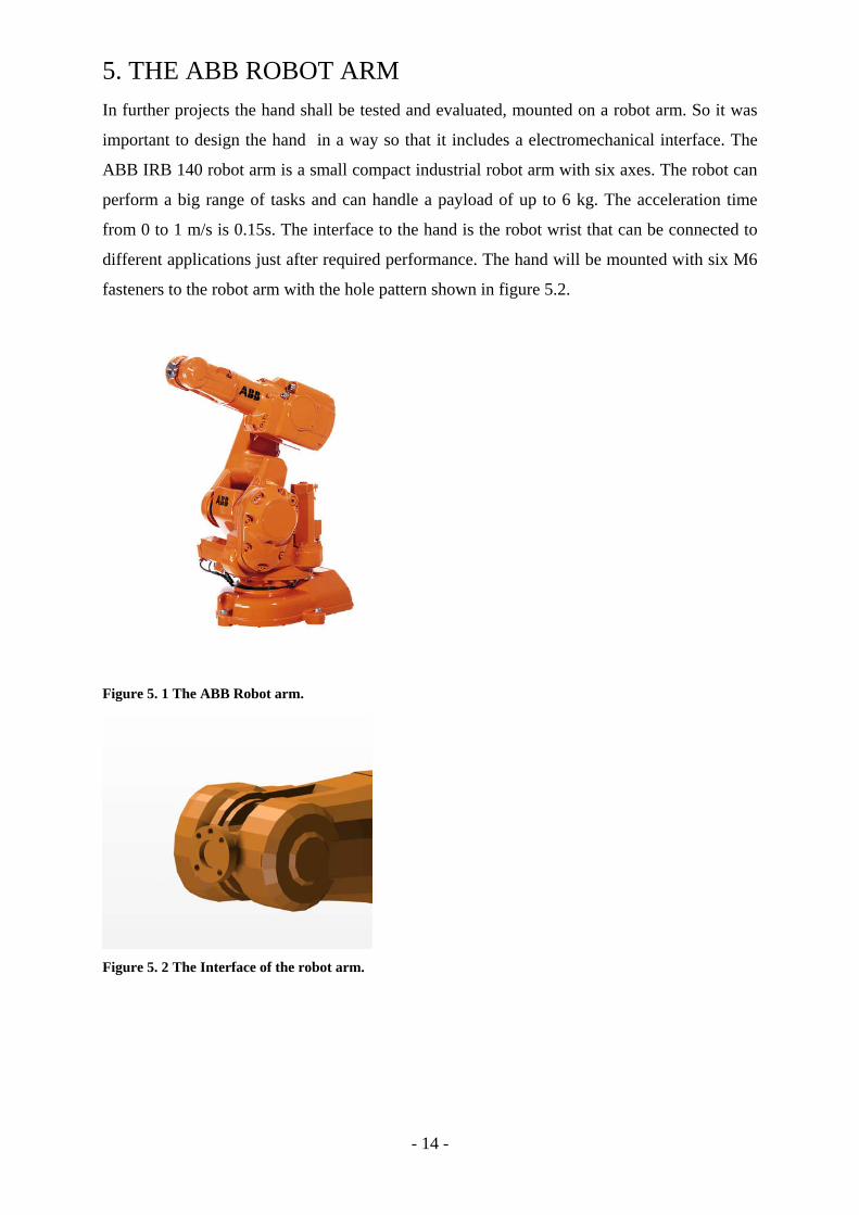
5. THE ABB ROBOT ARM In further projects the hand shall be tested and evaluated, mounted on a robot arm. So it was
important to design the hand in a way so that it includes a electromechanical interface. The
ABB IRB 140 robot arm is a small compact industrial robot arm with six axes. The robot can
perform a big range of tasks and can handle a payload of up to 6 kg. The acceleration time
from 0 to 1 m/s is 0.15s. The interface to the hand is the robot wrist that can be connected to
different applications just after required performance. The hand will be mounted with six M6
fasteners to the robot arm with the hole pattern shown in figure 5.2.
Figure 5. 1 The ABB Robot arm.
Figure 5. 2 The Interface of the robot arm.

- 15 -
6. ACTUATORS SENSORS AND ENCODERS The hand new hand should house 4 actuators, 10 Force sensors, three photo sensors and three
magnetic encoders. In the following chapter these components will be described.
6.1 THE MOTORS To bend and unbend the fingers, three actuators are required. The actuators in the existing
Tenex hand are from the STL Japan type and include a gearbox of a gear change of 1/297.
The motors have a god performance at a cheap price. The outgoing moment is 150 mNm.
Therefore are these motors to prefer before other motors which are smaller and have a better
performance but are much more expensive(datasheet appendix 8). So it was decided to order
three more STL Japan Motors (figure 6.1) for the new hand. These have differently to the
motors used in the previous hand even an outgoing axis on the motor side. This enables the
placing of an encoder on that side.
Figure 6. 1 The S.T.L. Japan Motor.
6.2 THE SERVO To perform the rotary movement of the thumb a servo from bluebird technologies is used in
the old hand. A Servo has a very strong torque at low dimensions and is suitable to realize the
rotary movement. So it was decided that even the servo shall stay the same in the new hand.
Figure 6. 2 The used Bluebird Servo.

- 16 -
6.3 THE OPTICAL ENCODER EE-SX1108 To implement speed control in the hand optical encoders are mounted on the outgoing axis of
the motor. The EE-SX1108 encoders are cheap and very small. They have a soldering pattern
and they are designed for the mounting on a printed circuit board.
6.3.1 FUNCTION
The encoders are read by photo sensors. A Diode works as an emitter and the light make the
transistor more conductive and the sensor send a 5 V signal. When the light source is covered
the signal is 0V. By that a pulse signal is created which reflects the current speed of the
motor. By that the actual finger speed can be calculated. The sensor has to be connected as
shown in figure 6.3.1.
Figure6. 3 Measurement Circuit.
6.3.2 DIMENSION AND ASSEMBLE PROPETIES
The sensors are 5x5x4 mm and are fitting just right in the hand. They are originally designed
for surface mounting on printed circuit boards and will be mounted by gluing and soldering
into the hand backside.
Figure 6. 4 Dimension and soldering pattern of the photo sensor.

- 17 -
6.4 THE ABSOLUTE ENCODER To measure the position of the fingers absolute encoders are mounted on the gearbox side of
the motor. These are from the As5040 type and are manufactured by Austria Microsystems
(figure 6.5). They are magnetic rotary encoders. With these encoders absolute angel
measurement can be implemented in the hand. The AS5040 is mounted on a printed circuit
board designed at KTH Machine Design. The dimensions are 18 mm x16 mm x 0. 8 mm. The
circuit board houses also two diodes. These give feedback if the encoder is in centered to the
magnet or not. They are turned off when the magnet and the encoder are centered and they are
shining when they are not.
Figure 6.5 Function and dimension of the AS5050 magnetic encoder.

- 18 -
6.5 THE FSR SENSORS The following section will describe the force sensors in a short way, more profound
information can be found in the previous project report [7].The hand is abled to measure
forces during grasping by force sensing resistors (FSRs).These sensors are built in three
different layers. One semiconductive layer, that is responsible for the changes in the
resistance when a force is applied onto the sensor. One space layer and also a conductive layer
made of plastic. By measuring the changes in the resistance the applied force can be
measured. The sensors used in the hand are from the type no.408 manufactured by Interlink
Electronics. They are sold as trimmable strips, the width of the sensors is 15, 4 mm and the
thickness is 0, 34 mm.
Figure 6.6 The FSR sensor.

- 19 -
7. DESIGN CONCEPTS In this chapter some aspects about the design, the shape and function of the hand will be
described. From the beginning there was one thought to design the whole hand in as few
different materials and different parts as possible. This keeps the manufacturing costs down
and to makes the manufacturing and assembling of the new hand timesaving.
7.1 CHOICE OF MATERIAL The existing hand is built in three different materials; aluminum, plastic, titan and steel. The
possibility to build the whole hand in plastic was tempting. This would enable to manufacture
the whole hand in Rapid Prototyping and that opens up for a very free design of the prototype.
At first the shape of the hand wouldn’t be limited by the manufacturing method. Second the
finger base could be integrated into the hand. Third, actuators, sensors, and cables can be
fastened directly in the palm (hand) and fourth, all parts would be manufactured to one price.
In the end the main parts of the fingers where manufactured by rapid prototyping so there
where god chances it would be possible to built the whole hand in the same material.
It was decided to do some research if it is possible to use the DS DURAFORM material (the
plastic used in rapid prototyping for the new hand) by looking up the material properties
(appendix 7) and by doing FEM analyses on the existing CAD files. The tensile strength of
the material is 42 MPa and the FEM analyses showed that the stress didn’t reach this level
even at the critical point at the finger base. The stress was 20 KPa. So after evaluating all this
point of views it was decided to built the new hand and also the fingers in DS DURAFORM
using Rapid prototyping.

- 20 -
7.2 DIFFERENT SHAPES AND INTERFACES As mentioned in the previous section the manufacturing method enabled to form the hand in
any shape. The figures 7.1 and 7.2 show two different concepts which have certain things in
common. The Base Phalanx is already integrated in the backside of the hand. They are
designed in two halves, the palm and the hand backside and the shape of the outer lines is
symmetric. One problem with these concepts was that they didn’t look very humanlike. One
reason for that was that the thumb is placed in the middle of the palm and not as at the human
hand at the back. Another reason is that the easiest placement of the motors (90 degrees to the
tendon) requires much space and makes the hand broad or long. The connection to the
external electronic components can be done by two 25D-Sub or one 37D-sub which can be
placed directly on the hand. Another alternative is to connect the d-subs to an outgoing cable.
To use an outgoing cable is a god solution on one side because the cable rooting in the hand
would be easier and it wouldn’t be necessary to solder the contacts to the d-sub in the hand.
On the other side that conveys the risk that contacts in the hand can be pulled out by pulling at
the outgoing cable. After evaluating these three concepts some conclusions where made.
1. The hand prototype had to become more anthropomorphic.
2. The root point of the thumb had to be moved backwards thus the distance between the
finger and the thumb had to remain the same.
3. The place where the D-subs are located should be used for the mechanical interface
not for the electronic.
4. The electronic interface had to be mounted on an outgoing cable not directly on the
hand.

- 21 -
Figure 7. 1 Hand backside with two dsubs.
Figure 7. 2 Hand backside with one D-subs.
- 22 -
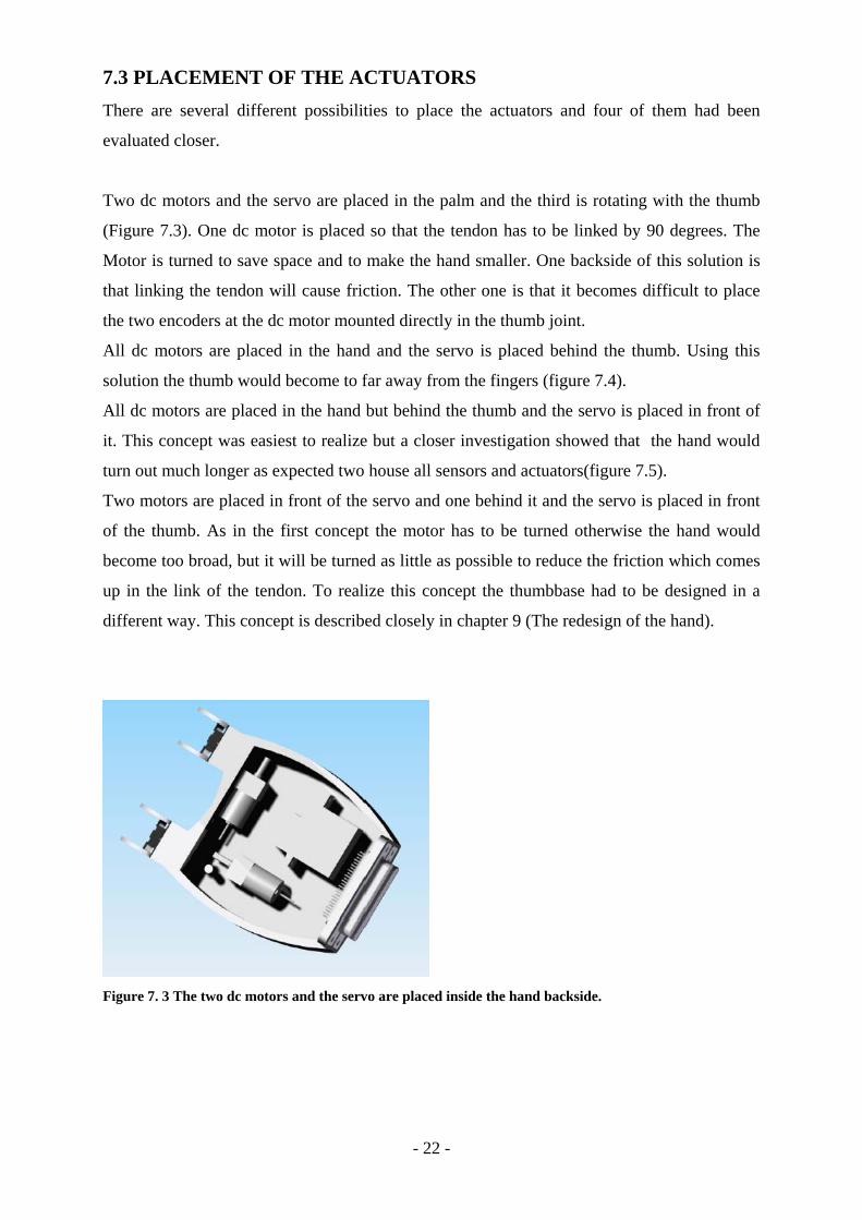
7.3 PLACEMENT OF THE ACTUATORS There are several different possibilities to place the actuators and four of them had been
evaluated closer.
Two dc motors and the servo are placed in the palm and the third is rotating with the thumb
(Figure 7.3). One dc motor is placed so that the tendon has to be linked by 90 degrees. The
Motor is turned to save space and to make the hand smaller. One backside of this solution is
that linking the tendon will cause friction. The other one is that it becomes difficult to place
the two encoders at the dc motor mounted directly in the thumb joint.
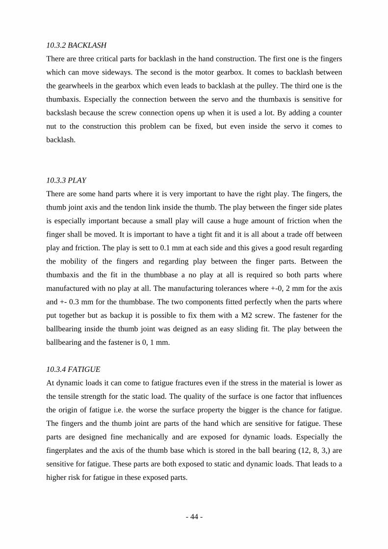
All dc motors are placed in the hand and the servo is placed behind the thumb. Using this
solution the thumb would become to far away from the fingers (figure 7.4).
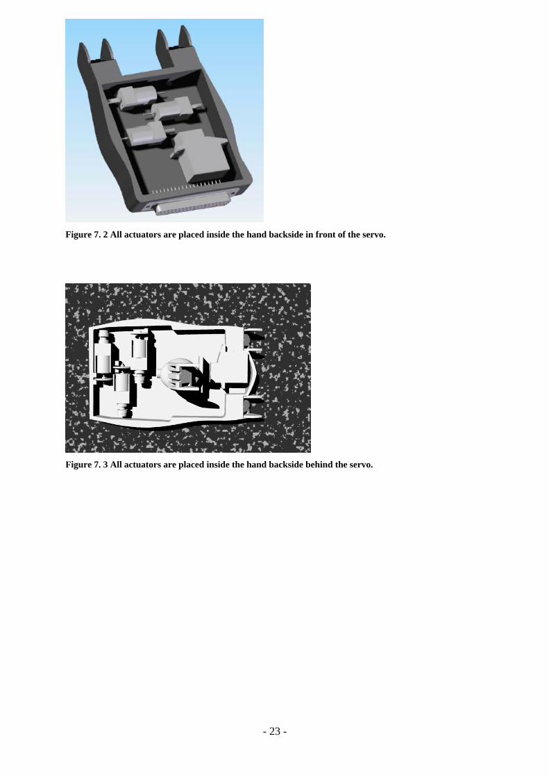
All dc motors are placed in the hand but behind the thumb and the servo is placed in front of
it. This concept was easiest to realize but a closer investigation showed that the hand would
turn out much longer as expected two house all sensors and actuators(figure 7.5).
Two motors are placed in front of the servo and one behind it and the servo is placed in front
of the thumb. As in the first concept the motor has to be turned otherwise the hand would
become too broad, but it will be turned as little as possible to reduce the friction which comes
up in the link of the tendon. To realize this concept the thumbbase had to be designed in a
different way. This concept is described closely in chapter 9 (The redesign of the hand).
Figure 7. 3 The two dc motors and the servo are placed inside the hand backside.
- 23 -
Figure 7. 2 All actuators are placed inside the hand backside in front of the servo.
Figure 7. 3 All actuators are placed inside the hand backside behind the servo.

- 24 -
7.4 PLACEMENT OF THE ACTUATORS AROUND THE THUMB
JOINT There where three different possibilities to place the actuators at the thumb joint. The easiest
is to place the motor besides the thumb joint so that it rotates with the whole joint. The other
two are to place the motor inside the hand backside and to link the tendon inside the
thumbbase and to lead it out of it through the rotation axis. The servo can be placed in front or
behind the thumbbase. The first thumb joint concept is illustrated in figure 7.5. The servo is
placed behind the thumb joint and the motor is placed in front of it. This concept allows it to
adjust the thumbbase in the shown shape closer to the fingers. The concept used in the final
design will be described closer in the chapter redesigning the thumb joint.
. Figure 7. 4 The Thumbbase with servo placed behind and the motor in front.

- 25 -
8. MOTORSYSTEM Some changes in the new hand had been made in the actuation and feedback control of the
fingers. It was important to make the finger stronger to coming closer to the goal of lifting a
2kg pet bottle. The incremental encoders are changed to an absolute encoder at the gearbox
side and an optical encoder is added on the motor side of the system. The diameter of the
pulley was made smaller to make the fingers more powerful. By reducing the diameter by one
millimeter the fingers become ¼ stronger but also ¼ slower. This means that the fingers now
can perform a string force of up to 40 N but the time to bend and unbend a finger is now
about 0,2-0,3 seconds slower.
The decision to make the fingers more powerful is based on two reasons. At first the aim
given in the task specification to grasp and lift a bottle with a weight of 2 kg couldn’t be
performed with the previous prototype. Second the thumb which is designed as a third finger
is to week to stand up to the forces performed by the two fingers on the opposite site. The
pulley is manufactured in DS DURAFORM as the most parts of the robotic hand. The magnet
is mounted on the pulley and it is important that the magnet can’t come in contact with the
gearbox axis which is made of steel because this would influence magnetic field and hence
the sensor readings.
Figure 8.1 The motor system, with motor, gearbox, sensor plate and pulley.

- 26 -
9. THE FINALDESIGN OF THE HAND In this chapter the final design process of the hand and its results will be described. The Final
design was influenced by all the concepts but is an execution of the fourth and last concept.
9.1 THE THUMBJOINT The thumb base is activated directly by the servo motor and emprises seven parts.
The thumb base shown in figure 9.1
The thumbaxis
The ball bearing for the link of the tendon inside the thumb joint
The two ball bearings for the bearing of the thumb joint axis
The two bearing blocks of the thumb joint
The form and function of the thumb joint had been changed from the first concept. These
changes had been done to make the shape of the hand more humanlike. Besides that it was
important to create one surface with the palm when the hand is fully open to make it easier to
perform grasp 15 (flat hand) in the Cutkosky grasping hierarchy.
Figure 9. 1 The thumbbase.

- 27 -
9.1.1 FUNCTION AND SHAPE
The angular form of the thumb makes it possible to move the bearing of the thumb more
backwards in the hand. The angel between the base foot and the base top is 120 degrees.
Simultaneously the thumb base comes five millimeters closer to the two finger bases. The
tendon which comes from the distal part of the thumb runs at the inside of the thumb base and
leaves the thumb right in the rotation axis of the thumb. The STL Japan motor is placed
behind the thumb base to roll up the tendon. The servo which performs the rotation of 90
degrees lies in front of the thumb joint (shown in figure 9.4).
Figure 9. 2 The thumbbase in three different views.
9.1.2 GUIDING THE TENDON
To change the angel of the fishing line inside the thumbbase the line had to be deflected. To
perform this function some kind of pulley was required. At the end a ball bearing with the
dimensions 10x4x4 was the best solution because this bearing is broad enough to mount o
rings on it to give some extra safety against the tendon jumping of the ball bearing (figure
9.4). Besides this guiding, the tendon is guided through two steering holes right before and
right after the link (figure 9.3) with the ball bearing. The tendon guiding are placed so that the
tendon runs tangential to the ball bearing to minimize friction.
Figure 9. 3 Section view of the thumbbase. Figure 9.4 Ball bearings with rings.

- 28 -
9.1.3 THE THUMBJOINTBEARINGS
The thumb axis is beard by two ball bearings of the dimensions 12x8x3mm, one on the servo
side and one on the outgoing side of the tendon. These ball bearings are mounted in two
bearing blocks fastened by M2x20 screws and nuts to the palm and the hand backside.
9.1.4 THUMBJOINTASSEMBLY
One specification was to reduce the parts of the thumb joint by 50 %. The thumb joint of the
first prototype (11.05.2007) consisted 16 different parts. The new thumb joint designed
(05.01.2008) includes eight parts the thumbbase, the thumb/servo axis, three ball bearings, the
two bearings, and the M2x30 screw. The whole motor system ha been moved from the
thumbbase into the hand backside that makes the hand more aesthetic and the motor system is
better protected.
Figure 9.6 The assembled thumbjoint.

- 29 -
9.2 PALMDESIGN This is the part of the hand which comes in contact with objects of different shapes and
dimensions. It is also the side of the hand which will be seen most often when the grasper is
active. Therefore it is important to have a functional, flat and good looking design (figure
9.7). Simultaneously it is important that the palm can tolerate the applied forces. There are
some functions the palm is made for besides covering the mechanics inside the hand. It
houses an FSR-sensor and it fastens all actuators inside the hand. It also gives stability to the
hand by mounting it together with the hand backside. The palm has two cutouts; one where
the thumb is placed, this cutout is shaped after the shape and the movement of the thumb. The
other one is placed at the front of the palm. This is where the FSR is mounted (figure 9.7).
The sensor can be inserted from behind trough the cutout and connected to the cables at the
backside of the palm. The depths at the inside of the palm are making space for sensors. The
heights are fastening sensors and actuators together with the hand backside.
Figure 9. 7 The palm with the cutouts for the FSR sensor and for the thumb.
9.3 DESIGNING THE BACK OF THE HAND All actuators, sensors and cables are housed in the hand backside (figures 9.8 and 9.9). As
mentioned earlier the manufacturing method makes it possible to integrate fasteners for these
parts directly in the hand so that just a few screws and no cable fasteners are required. The
Finger bases are included directly in the hand backside and the thumbbase. The two dc motors

- 30 -
are placed directly behind the finger base. The first one is placed 90 degrees to the tendon and
the second one is turned by 140 degrees (figure 9.10). This angel was influenced by three
factors. At first, it was important to take advantage of the space which was left besides the
thumb jointto make the hand smaller. Second, the closer the angel gets to 90 degrees to the
tendon the less friction is caused and third it was important to keep the hand in a human like
shape. Thus this makes the design more complicated because as in the thumb base a link of
the tendon is required to reduce the friction caused by changing the direction of the tendon
(figure 9.10). The Ball bearing is mounted on a hollow pillar which is stabilized by an M2x20
screw, that goes through the pillar and is fastened with a nut on the other side. This assembly
design is also used to mount the thumb joint in the hand backside and to fasten the palm and
the backside together. The hand backside has two cable holes with a M20 thread. Two cable
glands [15] can be fastened to fix the outgoing cables in the hand backside. That makes it
more difficult to pullout the cables by accident and decreases the risk for damage to the
sensors actuators and cables.
Figure 9. 8 The hand backside in three different views.

- 31 -
Figure 9. 9 The Handbackside.
Figure 9. 01. Section view of the tendon link with the mounted ball bearing.
9.4 DESIGNING THE ROBOTARM INTERFACE Also this part will be produced in DS Duraform and connects the hand to the ABB robot arm.
The interface is modular and consists two parts. The first is included in the hand back side and
is an extension of the named part. It has four holes for the screw connection and the holes for
the screw head have a big enough diameter to room the screw plates of a diameter of 4, 1 mm.
That’s to spread the tension on a bigger surface. The hole pattern of the hand fits the hole
pattern to the second module which can be designed in different ways. That makes it possible
to adjust the hand to different robot arms or to use it as en artificial limb.
Figure 9.10 The robot arm interface module.

- 32 -
Figure 9. 11 The manufactured interface.

- 33 -
9.5 THE SHAPE AND DIMENSIONS OF THE HAND One goal was to shape the hand more humanlike (figure 9.13 or appendix 1) and to be close to
the dimensions of a human hand. The shape and the lines are smooth and asymmetric as at the
human hand. The final robotic hand is 219 mm long, 95 mm with and 28 mm high. Statistics
shown in “Arbete-Människa-Teknik” on page 33 [3] show that, the human hand is at about
45 % of all man between 190 mm and 205 mm long, for women the measures are between
180 and 195 mm. The hand width for men (45 %) is between 85 mm and 95 mm and 75 mm
and 80 mm for woman (45 %). Comparing the dimensions of the tenex hand to the statistical
numbers it comes clear that the hand is bigger as the average male hand but matches about
five percent of the male population. So the goal to form the hand humanlike and even close to
the dimensions of a human hand could be achieved.
Figure 9.12 The hand mounted to the arm.

- 34 -
Figure 9. 13 The final hand in three different views.
Figure 9.14 The Tenex hand and the ABB robot arm.

- 35 -
9. 6 BEHAVIOR OF THE HAND UNDER LOAD FEM analyses (appendix 2) of the thumb base and the hand backside where done to get a
better understanding of their behavior under load .The conditions for the hand backside were
that it was locked at the interface to the robot arm and a load off 1, 5 kg was applied at the
outermost edge of the two finger bases. In two figures (appendix 2) the most sensitive
locations for deformation and stress are illustrated. The thumb base was locked around the
fastener for the thumb axis and a force of 30 N was applied to the most distal surface of the
thumb base. Also here the most sensitive locations for stress and deformation are illustrated in
figure three figures (appendix2). It also becomes clear that the yield stresses under the
applied loads by far don’t reach the tensile strength of the used material (42,3 Mpa).
10. EVALUATION OF THE PROTOTYPE In the following chapter the second prototype will be evaluated regarding it´s design,
manufacturing and function.
10.1 THE PROTOTYPE PARTS In this chapter all parts will be described concerning the manufacturing results. The tolerances
the Skara modellsnickeri could promise to hold +/-0, 3 mm. Earlier manufacturing orders
showed that the tolerances are usually far better and typically about +/-0, 1 mm.
10.1.1 THE HAND BACKSIDE
The part with fasteners for the servo, the motors, cables, encoders and the tendon link was
very important to get right. So at first it was tested if all this components match as they
should. This showed that the tolerances where small and the actuators could be mounted in
their fasteners by pushing them into place. Also, the tendon link is designed as a press and fit
connection. The 10x4x4mm ball bearing which shall be placed in the same way as the pulley
could be mounted applying a smooth pressure.
Figure 10. 1 The hand backside.

- 36 -
10.1.2 THE PALM
The cutout for the FSR was dimensioned after the dimensions of the sensor. Testing mounting
that sensor showed that the cutout was a little to small to assemble the parts without problems.
If the palm would be manufactured one more time the cutout should be dimensioned 0.5 mm
bigger in all directions.
Figure 10. 2 The palm with fasteners Figure 10. 3 The palm with the FSR mounted.
for actuators and sensors.
10.1.3 THE THUMB BASE
The thumb base houses the tendon link and fasteners for cables. The fitting for the ball
bearing has to be sliding so that the ball bearing can be mounted smoothly. The pour reach
ability (inside the thumb base) does not allow it to mount the ball bearing by applying
pressure. Also here the tolerances where god and the ball bearing could be mounted as
planned.
Figure 10. 1 The Thumb base with the two bearings.
10.1.4 THE THUMB BEARING BLOCKS
The two thumb bearings are meant to house the 12x8x3mm ball bearings. Also these should
be mounted and fastened by a press fit. So also here the tolerances were important. Both ball
bearings could be mounted as planned.

- 37 -
10.1.5 THE FINGERS
The rapid prototyping process creates a uneven surface in one dimension. So the fingers had
to be placed in a certain way during the manufacturing process to avoid the origin of marks in
the direction parallel to the finger. These marks would cause high friction in the finger joints.
The fingers are designed so that at each link side has 0, 1 mm space to the link side of the next
finger part. Here it’s important to get a matching that is precisely because the finger parts
have to slide easy at each other. Simultaneously it is important to avoid backslash in the
finger links. When the finger parts were put together for the first time it becomes obvious that
the surface was to rough and that the difference was less than 0, 1 mm. So the surfaces at the
finger side plates which are coming into contact with each other when the finger moves had to
be sandpapered to work up a little material an to get a finer surface.
Figure 10. 2 All parts needed to assemble a finger.

- 38 -
10.1.6 THE BALL BEARINGS AND THE TENDONGUIDE
These parts where designed as an additional safety backup for the tendon link. Their purpose
is to keep the tendon from jumping of the ballbearing. Also here the manufacturing results
where god and the plastic rings could be pressed into place (figure10.6). The inner size of the
rings is the same as the size of the ball bearings and can be mounted easily by elastic
deformation.
Figure 10. 3 The Ballbearing with the tendon steering mounted.
10.1.8 THE PULLEY
This part is meant to be a tight press matching together with the outgoing axis of the gearbox.
The matching has to be tight to avoid backslash between the axis and the pulley when the
tendon shall be rolled up and the torque of the motor shall be transmitted to the fingers. Being
aware of that problem pulleys in the whole tolerance range from 2, 7 mm to 3, 3 mm in
0,1mm steps where manufactured to find the right fit. So all together 21 pulleys where
manufactured. It appeared that the biggest pulley 3, 3 mm could be mounted by pressing it on
the axis but this matching result in a backslash when a force is applied through the motor. So
it was decided to make a shrink matching with the 3, 2 pulley.

- 39 -
10.2 TESTING THE PROTOTYPE This chapter describes the grasping characteristics of the new hand. The hand can still
perform six different grasps of the Cutcosky grasping hierarchy. Thus it was interesting to
investigate how or if the design changes will effect the grasping properties of the hand. More
profound information about the grasping properties of the old hand can be found in the
previous project report [6].
10.2.1 POSSIBLE GRASPS
All grasps mentioned in the Cutkosky grasping hierarchy where tested and eight grasps could
be performed. The thumb joint has just one DOF, but it is able to perform precision grasps
like the thumb one finger and the thumb two finger precision grasp. The hand can grasp a can
and all the finger parts and the thumb parts are in contact to the grasped object. The hand can
also grasp objects by using just the finger or just the thumb. That is done by pinning the
object between the fingers or between the thumb and the palm. The grasps performed can be
seen in figure 10.8 to 10.10.
Figure 10.8 Grasp 15, 9 and 16 from the left to the right.
Figure 10.9 Two additional Grasps (A1 A2)vand Grasp 1 from the left to the right.

- 40 -
Figure 10.10 Grasp 8 and 12 from the left to the right .
Grasp 1: Large diameter power grasp
Grasp 8: Thumb – 2finger precision grasp
Grasp 9: Thumb -1 finger precision grasp
Grasp 12: Disk precision grasp
Grasp 15: Flat hand
Grasp 16 : Lateral pinch grasp
Grasp A1: Thumb palm power grasp
Grasp A2: Two finger palm power grasp
10.2.2 FINGERVELOCITIES AND THEIR BEHAVIOR UNDER LOAD
The original finger design hasn’t changed from the old hand, but some changes to the
actuation of the fingers have been made. So the same tests as in the previous projects were
made and some improvements could be noticed (see table 10.1 to 10.4). The active and
passive holding force of the fingers was tested. Each part of the fingers was tested with a load
of 18 N (figure 10.11). The force of 18 N was the maximum value the fingers had been tested
with and not the maximum force they can take. By applying a higher force the screw
connection of the fingerplates would likely break. This was to avoid because the prototype
shouldn’t be destroyed but some damage experiments on one finger prototype can give a
clearer picture of how high forces one finger can take. The finger movement and the fingertip
force were of certain interest, the active holding force of the finger should increase by 25 %
because the diameter of the pulley was made smaller simultaneously the velocity of the finger
should become slower. As shown in table 10.1 to table 10.4 that is also the case. The
maximum shear force was also tested. That trough pulling with a dynamometer at a can,
which was grasped by the hand. The can started sliding at 26 N.
Table 10.1 Fingertip force of the new hand.

- 41 -
Table 10.2 Fingertip force of the old hand [6].
Table 10.3 Finger and thumb joint movement of the new hand.
Table 10.4 Finger and thumb joint movement of the old hand [6].
Figure 10.11 Finger parts with no load an a load of 18 N.

- 42 -
10.3 BENCHMARKING THE HAND The following chapter describes the benchmarking of the second prototype. The STL Japan
motor, play, backlash, and the hands behavior under load were benchmarked.
10.3.1 THE BREAKFUNKTION OF THE MOTOR AND POWER CONSUMTION OF THE
HAND
To get a better understanding of what forces the motor can exert actively and passively
experiments in three different applications had been carried out. Each had been repeated eight
times and a average value of each of the three experiments was calculated.
The force resistance of the motor and the gearbox
When the motor is not short circuit the exchange of the gearbox and the motors inner friction
can handle tendon forces up to 42 N (table10.3).
The force resistance with the break function of the motor activated
When the motor is short circuit it becomes a generator this leads to a bigger resistance of the
motor. This inner resistance divided with the exchange of the gearbox gives the passive force
exertion of the motor.
Active force exertion of the motor
The motors are driven by 5 V. At a maximal amperage of 0, 2 A the motor with the mounted
pulley exerts about 40 N see table 10.3. This means that the motor always can stand up to the
forces it had been exerted when it is turned off.

- 43 -
Table 10.3 Force extension of the motor.
Power consumption
The maximal power consumption of the STL Japan motors and the bluebird servo was
calculated to get a better understanding how much power is needed to move the hand and to
grasp objects. The current used is the average current of the product specification of the servo
and the motor.
- 44 -
10.3.2 BACKLASH
There are three critical parts for backlash in the hand construction. The first one is the fingers
which can move sideways. The second is the motor gearbox. It comes to backlash between
the gearwheels in the gearbox which even leads to backlash at the pulley. The third one is the
thumbaxis. Especially the connection between the servo and the thumbaxis is sensitive for
backslash because the screw connection opens up when it is used a lot. By adding a counter
nut to the construction this problem can be fixed, but even inside the servo it comes to
backlash.
10.3.3 PLAY
There are some hand parts where it is very important to have the right play. The fingers, the
thumb joint axis and the tendon link inside the thumb. The play between the finger side plates
is especially important because a small play will cause a huge amount of friction when the
finger shall be moved. It is important to have a tight fit and it is all about a trade off between
play and friction. The play is sett to 0.1 mm at each side and this gives a good result regarding
the mobility of the fingers and regarding play between the finger parts. Between the
thumbaxis and the fit in the thumbbase a no play at all is required so both parts where
manufactured with no play at all. The manufacturing tolerances where +-0, 2 mm for the axis
and +- 0.3 mm for the thumbbase. The two components fitted perfectly when the parts where
put together but as backup it is possible to fix them with a M2 screw. The fastener for the
ballbearing inside the thumb joint was deigned as an easy sliding fit. The play between the
ballbearing and the fastener is 0, 1 mm.
10.3.4 FATIGUE
At dynamic loads it can come to fatigue fractures even if the stress in the material is lower as
the tensile strength for the static load. The quality of the surface is one factor that influences
the origin of fatigue i.e. the worse the surface property the bigger is the chance for fatigue.
The fingers and the thumb joint are parts of the hand which are sensitive for fatigue. These
parts are designed fine mechanically and are exposed for dynamic loads. Especially the
fingerplates and the axis of the thumb base which is stored in the ball bearing (12, 8, 3,) are
sensitive for fatigue. These parts are both exposed to static and dynamic loads. That leads to a
higher risk for fatigue in these exposed parts.

- 45 -
11. CHARACTERISICS In the following section the characteristics of the hand are described and compared to the
specification. The structure of the section is the same as in chapter [3].
11.1 TASK CHARACTERISTICS
• The goal was to hold a 2 kg pet bottle .The hand can apply a shear force of 26 N, so it
is possible to hold a 1.5 l Pet bottle with a total mass of 1, 6 kg (figure 11.1).
• The hand can hold a box with approx. 1 kg mass (figure 11.2).
• The hand can hold a card between one forefinger and the thumb (figure 11.3).
• It is able to grasp a chocolate bar between one forefinger and the thumb.
• The hand is able to press a button with the forefingers and the thumb.
Figure 11.1 The second prototype grasping a 1.5 l pet bottle.
Figure 11.2 The second prototype grasping a box.

- 46 -
Figure 11.3 The second prototype grasping a card.
11.2 DESIGN CHARACTERISICS The dimensions and the shape of the hand are very close to the human ones (also section 9.5).
The length of the thumb differs from the human hand. The development of a thumb would
cost a lot of time and would for the most increase the shape of the hand and not the
functionality. Almost all design specifications could be fulfilled, just the electrical interface
could be realized halfway because the mounting of DSUBs would require much time
soldering all the contacts and wouldn’t make it much easier too exchange the new and the old
hand and the electronics.
The palm was redesigned and a modular interface to the ABB robot arm was constructed.
The palm and hand backside are housing all actuators and cables.
The electrical interface of the hand is composed of less than two industrial standard
connectors thus they are not mounted yet.
The palm houses a tactile sensor.
The hand is easier to assemble than the old hand (2007-08-11).
The thumb axis and the servo axis were centered.
The thumb position is adjusted at the second prototype (compare figuer11.4 and 11.5).
Forefingers and thumb are 5mm closer to each other. That enables a better grasping.
Cable routing for all cables exists.
Figure 11.4 The adjusted thumb grasping a can. Figure 11.5 The first prototype grasping a can.

- 47 -
11.3 PERFORMANCE CHARACTERISICS
A second prototype of a robot hand with three fingers was developed at a total project cost of
SEK 4600 kr. So the specification of developing a second prototype for SEK 2000 kr couldn’t
be met. One reason for that is that it was planned to use parts from the first prototype to build
the second. Another reason is that the manufacturing costs were underestimated. The cost of
build the hand from the beginning buying all components would be about SEK 12000 kr.
The measured weight of the prototype is 340 g. So the specification of 300 g couldn’t be
fulfilled. One reason for that is that the hand backside was over dimensioned. By removing
some unnecessary material and creating a lighter design the hand could be made between 25 g
and 30 g lighter. The 500 g of the previous project specification could be fulfilled and
exceeded with 32 %.
The finger tip force is 8 N active in the distal phalanx and 18 N passive. So the specification
of 10 N could only be fulfilled to 80 % in the grasping mode. In the holding mode the
specification could be fulfilled.
The fingers can be bent in 1, 3 seconds, the specification demands 1, 5 seconds so the
specification could be fulfilled and exceeded with 25 %.
The parts in the thumb joint could be reduced from 16 to eight so the specification of reducing
the number of parts in the thumb joint could be exerted.

- 48 -
12. LESSONS LEARNED The new hand was primarily designed to improve the shape and facilitate service and
assembly of the hand, but it was also important to get rid of the teething troubles of the first
prototype. Yet there are some improvements to do with this prototype.
The thumb joint bearings are manufactured in plastic and are mounted with M2x20 screws.
These screws are to short and don’t go through the whole hand as planned so they can’t be
fixed with the nuts. Instead the bearings should be manufactured in aluminum and fixed with
M2x30 screws and nuts. This would make the thumb joint construction much more stabile
and solid.
The optical sensor plate which rotates on the outgoing axis of the motor is very sensitive.
When it touches a cable or the hand backside the motor will stop immediately. The reason for
this is that this axis has a very low torque.
The motor boxes work fine as fasteners for the motors but the one behind the thumb joint was
placed one millimeter to close to the thumb. This leaded to following work on the prototype
and to a bad whole pattern between the thumb bearings and the hand backside. The fault had
been adjusted in the CAD files. At the Prototype this could be fixed by manufacturing two
new bearings in aluminum in the KTH workshop or by ordering one more hand backside at a
suitable moment (when there are other parts to be manufactured.)
The fracture assignment at the interface to the robot arm isn’t weak enough to ensure that
this part will break first. It could be made twice or three times weaker.

- 49 -
13. CONCLUSION A three finger robot hand could be developed at a total project cost of 550 €. The main parts
of the hand are manufactured by rapid prototyping using DS Duraform plastic. That method
made it possible to manufacture all parts to one price and was also timesaving because just a
few drawings had to be made.
The second hand prototype is working fine but some improvements could be made. By
redesigning the hand backside in a lighter construction the hand can become between 8-10 %
lighter. Also the interface of the hand can be improved by including a stronger fracture
assignment or by redesigning the hand in a way so that the interface is included into the palm.
That’s favorable because when the palm breaks just that part has to be exchanged. Nowadays
it would become necessary to change all actuators and sensors, if the hand backside breaks.
To sum things up, the goal to develop a functioning prototype and a interface to the robot arm
was fulfilled, the new hand can perform two more grasps using the palm and can grasp
objects in a better way. Also the assembly properties and cable routing could be improved.
Last but not least the new hand has dimensions close to the human ones and looks humanlike.

- 1 -
BIBLIOGRAPHY Literature

- 1 -
APPENDIX 1: DRAWINGS
The Drawings manufactured in the KTH Machine Design workshop are including all
measures of length and the tolerances are +- 0, 2 mm. The parts manufactured in the Skara
modellsnickeri are mainly not illustrated because that was not necessary for the
manufacturing, but some parts are illustrated to show their dimensions or certain design
details.


APPENDIX 2: FEM-ANALYSES

Name Value Convergence
-------------- ------------- -----------
max_beam_bending: 0.000000e+00 0.0%
max_beam_tensile: 0.000000e+00 0.0%
max_beam_torsion: 0.000000e+00 0.0%
max_beam_total: 0.000000e+00 0.0%
max_disp_mag: 1.551063e+08 1.0%
max_disp_x: 2.752458e+07 0.9%
max_disp_y: -7.519865e+06 1.0%
max_disp_z: 1.532054e+08 1.0%
max_prin_mag: 2.046139e+04 15.5%
max_rot_mag: 0.000000e+00 0.0%
max_rot_x: 0.000000e+00 0.0%
max_rot_y: 0.000000e+00 0.0%
max_rot_z: 0.000000e+00 0.0%
max_stress_prin: 2.046139e+04 15.5%
max_stress_vm: 1.839717e+04 11.9%
max_stress_xx: 1.878207e+04 18.0%
max_stress_xy: -1.048634e+04 11.6%
max_stress_xz: 6.660261e+03 16.6%
max_stress_yy: -1.099713e+04 2.1%
max_stress_yz: 4.300081e+03 2.5%
max_stress_zz: 9.824300e+03 17.1%
min_stress_prin: -1.758442e+04 10.2%
strain_energy: 1.288400e+12 1.1%


Resultant Load on Model:
in global X direction: 1.488329e-08
in global Y direction: 9.217988e-10
in global Z direction: 3.000000e+04
Measures:
Name Value Convergence
-------------- ------------- -----------
max_beam_bending: 0.000000e+00 0.0%
max_beam_tensile: 0.000000e+00 0.0%
max_beam_torsion: 0.000000e+00 0.0%
max_beam_total: 0.000000e+00 0.0%
max_disp_mag: 3.412082e+07 2.4%
max_disp_x: 1.352688e+07 2.1%
max_disp_y: -3.289546e+06 8.6%
max_disp_z: 3.194036e+07 2.4%
max_prin_mag: 4.446599e+04 17.5%
max_rot_mag: 0.000000e+00 0.0%
max_rot_x: 0.000000e+00 0.0%
max_rot_y: 0.000000e+00 0.0%
max_rot_z: 0.000000e+00 0.0%
max_stress_prin: 4.446599e+04 17.5%
max_stress_vm: 3.891670e+04 17.6%
max_stress_xx: 4.167295e+04 16.1%
max_stress_xy: -6.295829e+03 1.6%
max_stress_xz: 1.402057e+04 2.6%
max_stress_yy: 1.495838e+04 20.3%
max_stress_yz: 5.094920e+03 11.0%
max_stress_zz: 2.357535e+04 31.1%
min_stress_prin: -1.959093e+04 5.7%
strain_energy: 3.113082e+11 2.5%

APPENDIX 3: FORCES IN THE THUMBJOINT

APPENDIX 4: BOM
The bill of materials, or parts list, is like an index to the product. It is good practice to generate the
bill of materials as the product evolves (David G. Ullman The mechanical design process page
181). This BOM shows the most important product part information’s, a more detailed BOM can
be found in the extra document map.

APPENDIX 5: RISK ANALYSES This sheet was written after the final design review and before pars where order to get a better
understanding of what the risks are regarding manufacturing and the design of the hand.
After the review of this document some final adjustments had been made to get done with
those risks or to reduce them.
Manufacturing risks
What are the manufacturing tolerances for rapid prototyping? How big becomes the
difference between covet measure and real measure? l. Leads to a too big or too small fit.
This can lead to backlash in the pulley or that the ball bearings don’t match. Wrong placement
of the finger parts during the manufacturing process leads to friction between the finger parts.
Details which shall be manufactured in the Workshop can’t be manufactured by milling or
turning.
Design risks
The Pulley
The pulley can start to backlash if it is to big for the gearbox axis. It can also come to fatigue
fractures in the pulley.
Thumb joint
There is too little space for cables and the tendon inside the thumb base that can lead to
mounting difficulties and that the tendon and the cables can tangle into each other. The string
routing can jump of the ball bearing. The thumb joint can be to week, it’s the weakest item in
the whole construction. The thumb has to stand up to two fingers.
The Interface
This part is very sensitive for bumps. If the robotic hand crashes with another object under an
operation it will break there. The interface is integrated in the hand back side which houses
almost all sensors and all actuators. The whole hand has to be disassembled when it has to be
repaired. The interface has to stand up to the own mass plus an external load of 2 kg.
Counteracting the risks

Backup parts can be manufacturen in the KTH Workshop (Interface, Pulley, Thumb joint).
Washers to divide the tensions on to a bigger surface. Contact the manufacturer (skara
modellsnickeri) and get better information about the tolerances and inform them detailed
about how the fingers have to be placed under the manufacturing process. The Pulley ca be
matched by warming it up and mounting it then on the encoder another option is to order
different pulley through out the whole tolerance range. Ball bearings with a bigger sliding
surface can be order to reduce the risk of jumping of beside that, steering rings can be
mounted on the ball bearings. Add material in the thumb joint where it is required.

APPENDIX 6: ASSEMBLE THE HAND In this document it will be described step by step how to assemble the hand. Assembling the
hand the first time took three days which was longer as expected because some smaller
adjustments at the prototype hand to be made. Assemble the hand one more time with all
components fitting as they should is possible in about one day.
Assemble the fingers 1.1Cut the FSr´s into the shape shown on the figure ..and connect them to the cables with the conductive epoxy.
Figure 13. 1 FSR`s mounted on the finger Figure 13. 2 Cables fasted with conductive epoxy
1.2 Glue the sensors onto the grasping surface o0f the finger parts. 1.3 Lead the tendon and the cables through the finger parts. By that the finger parts are put together. 1.4 Take the spring leaf and mount it with the M2*8 (M2*6) and the screw plates on the finger backside. 1.5 Lead the cables and the tendon through the cable and tendon holes into the hand backside and fasten the fingers with the spring leaf, the screw plates and the M2x8 screws at the hand backside. 1.6 Install cable routing in the hand backside and lead the cables through the cable glands. Assemble the thumb joint
2.1 Assemble the proximal phalanx, the middle phalanx and the distal phalanx as in
section.
2.2 Lead the cables and the tendon through the thumbbase. 3.3 Fasten the finger at the thumbbase with the M2X8 screw and the screw plate. 2.4 Mount the ball bearing in the thumb and fasten it with the M2x20 screw. 2.5 Lead the tendon out of the thumbbase. 2.6 Mount the ball bearing 8,5x12x3 on the thumbaxis. The other bearing shall be mounted at the bearing which will be installed behind the thumbbase 2.7 Mount the thumb axis on the servo axis. 2.8 Fasten the servo axis and the thumbaxis with the M1X 3 Screws 2.9 Assemble the bearing at the front of the thumb with the servo and the thumb axis.

2.10 Attach the two parts together (servo, thumb axis, front bearing,) and (thumbbase, bearing at the back). Fasten the thumb joint and the axis with an M2 screw. 2.11 Attach the thumb joint to the hand backside by pressing it into the fasteners.
Figure 13. 3 Thumb joint and fingers mounted
Figure 13. 4The thumb joint assembled
3. Install the photo sensors and the absolute encoders in the hand and lead the cables out
trough the cable glands.
Figure 13. 5 Encoder and pulley mounted Figure 13. 6 The photo sensor mounted
4. Mount the optical encoder on the gearbox axis.
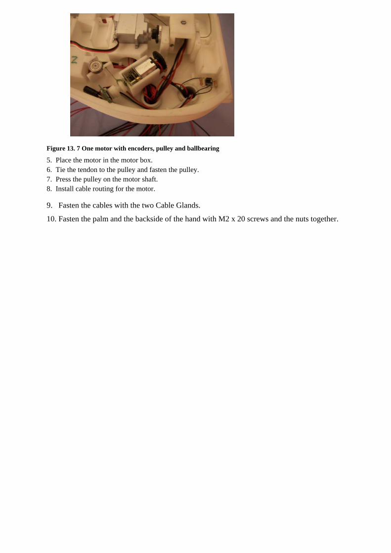
Figure 13. 7 One motor with encoders, pulley and ballbearing 5. Place the motor in the motor box. 6. Tie the tendon to the pulley and fasten the pulley. 7. Press the pulley on the motor shaft. 8. Install cable routing for the motor.
9. Fasten the cables with the two Cable Glands.
10. Fasten the palm and the backside of the hand with M2 x 20 screws and the nuts together.

APPENDIX 7: DURAFORM DATA SHEET


APPENDIX 8: DATASHEET STL JAPAN MOTOR (translated by Satoshi Yoneyama)