robatic roba -quick roba - · pdf filepower transmission ® 3 robatic® electromagnetic...
TRANSCRIPT

K.500.V02.GB
ROBATIC®
ROBA®-quickROBA®-takt
ww
w.m
ayr.
de Electromagnetic Clutches and Brakes,
Clutch Brake Units
● High torque capacity● Low wear● Easy assembly and maintenance● Compact construction
Reliable couplingand brakingReliable coupling and braking
Equipment TechnologyPackaging MachineryConveyors and Materials Handling EquipmentDoor drivesIndexing tables
powertransmission

powertransmission
®
2
Your advantages when using Electromagnetic
ROBATIC®-Clutches, ROBA®-quick Brakes and
ROBA®-takt Clutch Brake Units
• Easy integration into your machine:The optimised magnetic circuit minimises themagnetic stray flux. The high power density and torque security based on it allow compact dimensions and an easy integration in your construction.
• High reliability and operational security:The switching behaviour is constant during the whole service life. Therefore, the positioningaccuracy and reliability of the clutches or brakes respectively and herewith operational security ofyour machine are increased.
• Less operating expenses and maintenancecharges:The large friction surface and the smooth switchingbehaviour increase the wear resistance, therefore,the clutches and brakes are maintenance-free untilthe friction faces are worn down.
• Increase of the productivity:Short switching times allow high switching frequency and increase the productivity of yourmachine.
mayr® Power Transmission have applied the highesttechnical and innovative standard for decades. Thefoundation for this success are the skills, productivityand quality consciousness of all mayr® employees.
The DIN ISO 9001 certification achieved confirms thehigh demands we set to experience, together with totalour engineering integrity, and quality manufacturingprocesses. mayr® Power Transmission offers you acomprehensive depth of management to ensure yourconfidence, and many years’ expertise, gained in bothmechanical and electrical power transmission, confirmsour position as leaders in this field.
Quality, Experience, Competence
All products are subject to comprehensive inspectionsand tests regarding loads. Only after having passed thestrongest long-time tests and when they fully meet allthe technical requirements and proof their reliabilitythey are included in our delivery programme.

powertransmission
®
3
ROBATIC® Electromagnetic Clutch
Definition of termsThe torque (nominal torque)(= switching torque) is the torque acting on the shafting with a slippingclutch or brake.
The transmittable torqueis the largest torque with which the closed clutch or brake can beloaded without an occurrence of slipping.
At a rated-load operating temperature the permanent temperatureis achieved. This temperature is the amount from the determinedover-temperature and the reference temperature.
Protection class I is not only based on the basis isolation, but thatall conductive magnetic parts must be connected with the protectiveconductor of the fixed installation. In this case, if the basis isolationfails, no contact voltage can remain existing.
The relative switch-on duration is the ratio of switch-on duration tothe cycle duration in percentage (% switch-on duration).
Description of the unitThe catalogue values are reference values, which can deviate inindividual cases.When selecting the clutch or brake, mounting situation, torquefluctuations, permissible friction work, behaviour during run-in, wearand ambient conditions are to be carefully checked and agreed withthe unit manufacturer.The mounting and connecting dimensions at the site of installationmust match to the size of the units.The clutches and brakes are designed for a dry running. They achievethe catalogue-torque, when the friction linings are run-in. Normallythese are approx. 100 switchings with a dynamic operation.In a new condition approx. 50 % of the catalogue-torque (Mü) istransmitted. Clutches or brakes used statically or quasi-statically (i.e.small friction work) do not achieve the torque (Mü) indicated in theTables.This case is given if the clutch or brake falls below the speed orfriction work (Qa) indicated in Table 1. Should oil, grease or similarmaterials come in contact with the friction surfaces the torque couldbe reduced drastically.When switching off the units voltage peaks can occur due to themutual inductance of the magnetic coils which can cause a damageof the units in the extreme case. Therefore, the overvoltage is to bedamped by a “protective wiring”.The surfaces of the clutches and brakes are protected againstcorrosion. Provide additional necessary safety measures againstcorrosion, if they are used under extreme ambient conditions or in theopen with direct atmospheric influence. The connecting cables orwires of the clutches and brakes have a sheathing on silicone basis,which is not resistant to all materials. The compatibility is to beexamined when contacting chemical materials. The clutches andbrakes are designed for a relative switch-on duration of 100 %.
Size Friction work Qa Clutch or brake speed nmin[J] [rpm]
3 16 300
4 29 250
5 55 200
6 105 160
7 200 130
8 380 120
9 600 100
Table 1
☞
Vorsicht
!
Wichtig☞
Manufacturer’s declarationmayr®-clutches and mayr®-brakes are to be seen asan option or component for installation into machinesor equipment according to the machinery directive.The machinery must not be put into service until themachinery into which it is to be incorporated hasbeen declared in conformity with the provisions of theapplicable EC-directives.The product corresponds to the low-voltage directive73/23/EEC.
Note: There are no emissions from the listed single components within themeaning of the EMC-directive, however, increased interference levelscan occur when working components are operated outside theirspecification limits as for example rectifiers and clutches or brakes.Therefore, the installation and operating instructions must be readcarefully and the EMC-directives are to be observed.
Safety regulationsAttention!Hazardous conditions when contacting hotconnections and components.Only qualified and well-trained specialists shouldwork on the units to avoid any personal injury ordamage to machinery.
Please observe!The indication of the catalogue as well as the installation and operating instructions must be readcarefully and all safety regulations observed beforedesign, installation, initial start-up or maintenance ofthe units.
Inappropriate application of the technical data cause losses andmaterial damages, for which no liability is assumed.
Therefore please observe!
– Correct supply connection according to Type tag.– Assembly, maintenance or repair must not be made when the unit
is energised.– Electrical leads must not be under tension when connected.– Check current carrying components regarding damage before an in
initial start-up.- Current carrying components must not be in contact with water.
Necessary protective measures to be undertaken by the user:– Cover all moving parts to prevent personnel injury as squeezing and
seizing.– Attach a conductive connection between magnetic part and
electrical conductor (PE) of the fixed installation (protection class I)to prevent electrical shock.
– Protection against high inductive cut-off peaks by fitting sparkquenching units.
– Protection against dangerously hot temperatures at the magneticpart by attachment of a cover.
Standards and Instructionsmayr®-clutches and mayr®-brakes correspond to the nationalstandard DIN VDE 0580/7/2000, according to the low voltagedirective 73/23/EEC.
Device – protection class I.
Protection IP 00 mechanical design (armature disc, rotor,friction lining, incl. magnetic coil)
Protection IP 54 electric design (magnetic coil, encapsulatedor injection-moulded and connecting cable)
Thermal class F up to 155 °C for magnetic coil encapsulatedwith moulding compound
Thermal class B up to 130 °C for magnetic coil plastic-extrusion-coated
Ambient temperature up to +35 °C
Caution
Important

powertransmission
®
4
Table of contents
ROBATIC®
ElectromagneticEnergise to engagePole face clutches
Pages 5 to 8
ROBA®-quickElectromagneticEnergise to engagePole face brakes
Pages 19 to 27
ROBA®-takt Clutch Brake ModuleClutch Brake Units
Pages 28 to 36

powertransmission
®
5
ROBATIC® Electromagnetic Clutch
Constant switching performancethroughout the total service life
High torque securitydue to an optimised magnetic field and the new design of the ROBATIC®-clutch. Therefore, higher capacities due to fewmagnetic field losses.
Half the weardue to large friction surfaces and smooth switching behaviour the ROBATIC®-clutch has ahigher wear resistance (approx. 100 %).
Low noise
Short switching times/high switching frequencies
Correct function until end of wear
Large permissible shaft diameters due to largeinternal diameters of the magnetic coil bodies.

powertransmission
®
6
ROBATIC® Electromagnetic Clutch
FunctionROBATIC®-clutches are „energise to engage“, electromagneticpole face units.
If a DC voltage is applied to the magnetic coil (1) a magnetic fieldis formed, the armature disc (3) is attracted to the rotor (2) andfriction lining (4). The torque is transmitted via a friction connection.
The torque is transmitted from the drive element (6) via the armature disc (3) and the rotor (2) to the output shaft (7).
After having de-energised the coil, the membrane spring (5) draws back the armature disc (3) to the drive element (e.g. beltpulley), and the torque transmission is then disconnected.
7 1 2 4 6
3 5

powertransmission
®
7
ROBATIC® summary of components
ROBATIC® -standard
Page 8
ROBATIC® –small mounting diameter
Page 11
ROBATIC® –with bearing supported coil carrier
Page 13
ROBATIC® –with bearing supported output flange
Page 14
Technical explanations
Page 15
Electrical accessories
Page 37
powertransmission
®
8
ROBATIC® Electromagnetic Clutch
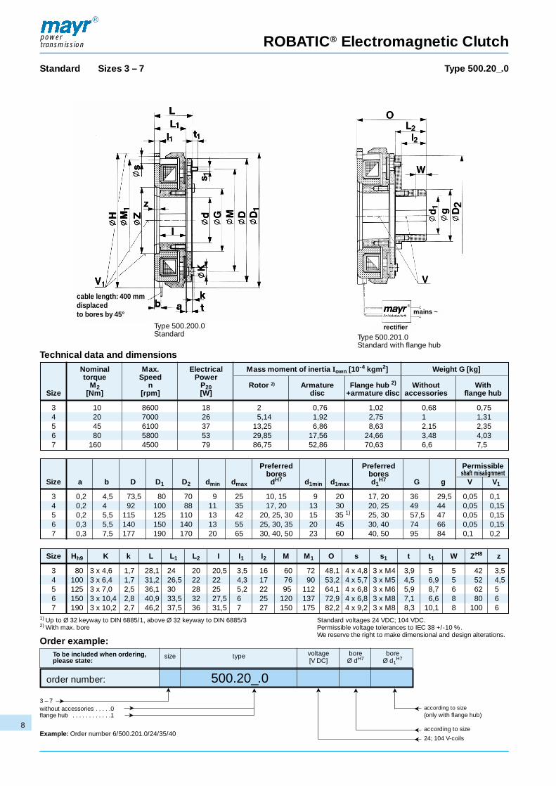
Standard Sizes 3 – 7 Type 500.20_.0
Technical data and dimensionsNominal Max. Electrical Mass moment of inertia Iown [10-4 kgm2] Weight G [kg]torque Speed Power
M2 n P20 Rotor 2) Armature Flange hub 2) Without WithSize [Nm] [rpm] [W] disc +armature disc accessories flange hub
3 10 8600 18 2 0,76 1,02 0,68 0,754 20 7000 26 5,14 1,92 2,75 1 1,315 45 6100 37 13,25 6,86 8,63 2,15 2,356 80 5800 53 29,85 17,56 24,66 3,48 4,037 160 4500 79 86,75 52,86 70,63 6,6 7,5
Preferred Preferred Permissiblebores bores shaft misalignment
Size a b D D1 D2 dmin dmax dH7 d1min d1max d1H7 G g V V1
3 0,2 4,5 73,5 80 70 9 25 10, 15 9 20 17, 20 36 29,5 0,05 0,14 0,2 4 92 100 88 11 35 17, 20 13 30 20, 25 49 44 0,05 0,155 0,2 5,5 115 125 110 13 42 20, 25, 30 15 35 1) 25, 30 57,5 47 0,05 0,156 0,3 5,5 140 150 140 13 55 25, 30, 35 20 45 30, 40 74 66 0,05 0,157 0,3 7,5 177 190 170 20 65 30, 40, 50 23 60 40, 50 95 84 0,1 0,2
Size Hh9 K k L L1 L2 I I1 I2 M M1 O s s1 t t1 W ZH8 z
3 80 3 x 4,6 1,7 28,1 24 20 20,5 3,5 16 60 72 48,1 4 x 4,8 3 x M4 3,9 5 5 42 3,54 100 3 x 6,4 1,7 31,2 26,5 22 22 4,3 17 76 90 53,2 4 x 5,7 3 x M5 4,5 6,9 5 52 4,55 125 3 x 7,0 2,5 36,1 30 28 25 5,2 22 95 112 64,1 4 x 6,8 3 x M6 5,9 8,7 6 62 56 150 3 x 10,4 2,8 40,9 33,5 32 27,5 6 25 120 137 72,9 4 x 6,8 3 x M8 7,1 6,6 8 80 67 190 3 x 10,2 2,7 46,2 37,5 36 31,5 7 27 150 175 82,2 4 x 9,2 3 x M8 8,3 10,1 8 100 6
1) Up to Ø 32 keyway to DIN 6885/1, above Ø 32 keyway to DIN 6885/3 Standard voltages 24 VDC; 104 VDC.2) With max. bore Permissible voltage tolerances to IEC 38 +/-10 %.
We reserve the right to make dimensional and design alterations.Order example:
To be included when ordering, size type voltage bore bore please state: [V DC] Ø dH7 Ø d1
H7
order number: 500.20_.0
3 – 7 without accessories . . . . .0flange hub . . . . . . . . . . . .1
Example: Order number 6/500.201.0/24/35/40
according to size(only with flange hub)
according to size
24; 104 V-coils
Type 500.200.0Standard Type 500.201.0
Standard with flange hub
➤ ➤
➤➤➤
➤➤ ➤
➤
➤
➤
cable length: 400 mmdisplacedto bores by 45°
rectifier
mains ~
powertransmission
®
9
ROBATIC® Electromagnetic Clutch
Order example:
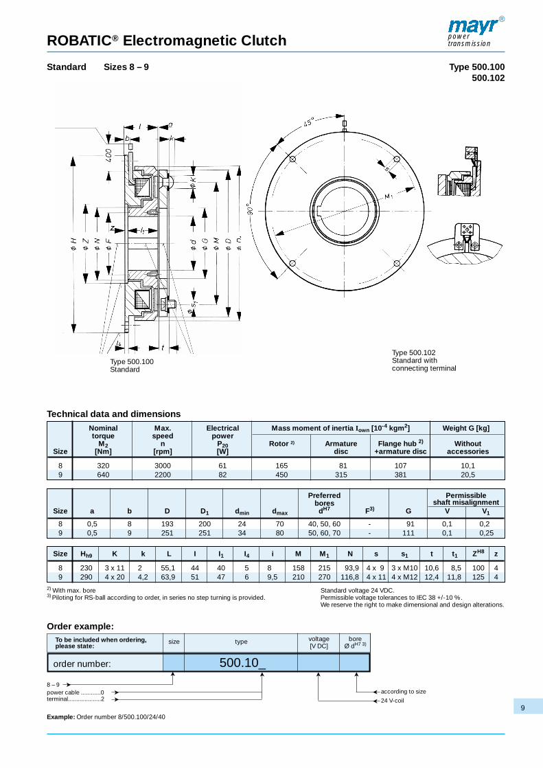
Standard Sizes 8 – 9 Type 500.100500.102
Technical data and dimensionsNominal Max. Electrical Mass moment of inertia Iown [10-4 kgm2] Weight G [kg]torque speed power
M2 n P20 Rotor 2) Armature Flange hub 2) WithoutSize [Nm] [rpm] [W] disc +armature disc accessories
8 320 3000 61 165 81 107 10,19 640 2200 82 450 315 381 20,5
Preferred Permissiblebores shaft misalignment
Size a b D D1 dmin dmax dH7 F3) G V V1
8 0,5 8 193 200 24 70 40, 50, 60 - 91 0,1 0,29 0,5 9 251 251 34 80 50, 60, 70 - 111 0,1 0,25
Size Hh9 K k L I I1 I4 i M M1 N s s1 t t1 ZH8 z
8 230 3 x 11 2 55,1 44 40 5 8 158 215 93,9 4 x 9 3 x M10 10,6 8,5 100 49 290 4 x 20 4,2 63,9 51 47 6 9,5 210 270 116,8 4 x 11 4 x M12 12,4 11,8 125 4
2) With max. bore Standard voltage 24 VDC.3) Piloting for RS-ball according to order, in series no step turning is provided. Permissible voltage tolerances to IEC 38 +/-10 %.
We reserve the right to make dimensional and design alterations.
To be included when ordering, size type voltage bore please state: [V DC] Ø dH7 3)
order number: 500.10_
8 – 9power cable ............0terminal....................2
Example: Order number 8/500.100/24/40
according to size
24 V-coil
➤ ➤
Type 500.102Standard with connecting terminal
Type 500.100Standard
➤
➤➤
➤ ➤
➤
➤

ROBATIC® Electromagnetic Clutch
Standard Sizes 8 – 9 Type 500.11_
powertransmission
®
10
Technical data and dimensionsNominal Max. Electrical Mass moment of inertia Iown [10-4 kgm2] Weight G [kg]torque speed power
M2 n Typ P20 Rotor 2) Flange hub 2) Without WithSize [Nm] [rpm] 500 [W] +armature disc accessories flange hub
8 320 3000 61 165 107 10,1 139 640 2200 82 450 381 20,5 25
Preferred Preferred Permissiblebores bores shaft misalignment
Size a b D D1 D2 dmin dmax dH7 d1min d1max d1H7 F3) g V V1
8 0,5 8 193 200 185 24 70 40, 50, 60 24 60 40, 50 - 84 0,1 0,29 0,5 9 251 251 242 34 80 50, 60, 70 27 80 50, 60 - 104 0,1 0,25
Size Hh9 K k L2 I I1 I2 I4 M1 N O s W ZH8 z
8 230 3 x 11 2 45,3 44 40 36,3 5 215 93,9 100,4 4 x 9 15 100 49 290 4 x 20 4,2 53,9 51 47 42,9 6 270 116,8 117,8 4 x 11 20 125 4
2) With max. bore Standard voltage 24 VDC.3) Piloting for RS-ball according to order, in series no step turning is provided. Permissible voltage tolerances to IEC 38 +/-10 %.
We reserve the right to make dimensional and design alterations.
Order example:To be included when ordering, size type voltage bore bore please state: [V DC] Ø dH7 Ø d1
H7
order number: 500.11_
8 – 9 power cable ............0 terminal ...................2
Example: Order number 8/500.110/24/40/40
according to size
according to size
24 V-coil
Type 500.110Standard with flange hub
➤ ➤
➤
➤➤
➤➤ ➤
➤
➤
➤

ROBATIC® Electromagnetic Clutch
Small mounting diameter Sizes 3 – 7 Type 500.21_.0
powertransmission
®
11
Technical data and dimensionsNominal Max. Electrical Mass moment of inertia Iown [10-4 kgm2] Weight G [kg]torque speed power
M2 n P20 Rotor 2) Armature Flange hub 2) Without WithSize [Nm] [rpm] [W] disc +armature disc accessories flange hub
3 10 8600 18 2,2 0,7 0,8 0,65 0,74 20 7000 26 5,3 1,79 1,97 1,1 1,165 45 6100 37 13,47 6,28 7,19 2,1 2,256 80 5800 53 32,31 15,77 17,45 3,4 3,67 160 4500 79 90,13 48,1 55,2 6,4 6,95
Preferred Preferred Permissiblebores bores shaft misalignment
Size a b D D1 D2 dmin dmax dH7 d1min d1max d1H7 G g V V1
3 0,2 4,5 73,5 80 54 9 20 10, 15 8 17 10, 15 36 27 0,05 0,14 0,2 4 92 100 70 11 28 17, 20 9 20 17, 20 49 29,5 0,05 0,155 0,2 5,5 115 125 88 13 35 20, 25, 30 13 30 20, 25 57,5 44 0,05 0,156 0,3 5,5 140 150 110 13 42 25, 30, 35 15 35 1) 25, 30 74 47 0,05 0,157 0,3 7,5 177 190 140 20 55 30, 40, 50 20 45 30, 40 95 66 0,1 0,2
Size Hh9 K k L L1 L2 I I1 I2 M M1 O s s1 t t1 W ZH8 z
3 80 3 x 4,3 1,5 28,1 24 15 22 3,5 11,5 46 72 43,1 4 x 4,5 3 x M3 3,9 4,0 5 35 24 100 3 x 4,6 1,7 31,1 26,5 20 24 4,3 16 60 90 51,1 4 x 5,7 3 x M4 4,4 5,0 5 42 2,55 125 3 x 6,4 1,5 36,1 30 22 27 5,2 17 76 112 58,1 4 x 6,8 3 x M5 5,9 6,8 6 52 36 150 3 x 7 2,2 40,8 33,5 28 30 6 22 95 137 68,8 4 x 6,8 3 x M6 7,0 8,5 8 62 3,57 190 3 x 10,4 2,7 45,9 37,5 32 34 7 25 120 175 77,9 4 x 9,2 3 x M8 8,1 8,4 8 80 3,5
1) Up to Ø 32 keyway to DIN 6885/1, above Ø 32 keyway to DIN 6885/3 Standard voltages 24 VDC; 104 VDC.2) With max. bore Permissible voltage tolerances to IEC 38 +/-10 %.
We reserve the right to make dimensional and design alterations.Order example:
To be included when ordering, size type voltage bore bore please state: [V DC] Ø dH7 Ø d1
H7
order number: 500.21_.0
3 – 7 without accessories .......0 flange hub ......................1
Example: Order number 6/500.211.0/24/40/30
according to size(only with flange hub)
according to size
24; 104 V-coils
Type 500.210.0Small mounting diameter Type 500.211.0
Small mounting diameter with flange hub
➤ ➤
➤➤➤
➤➤ ➤
➤
➤
➤
cable length:400 mm displacedto bores by 45°
rectifier
mains ~
powertransmission
®
12
ROBATIC® Electromagnetic Clutch
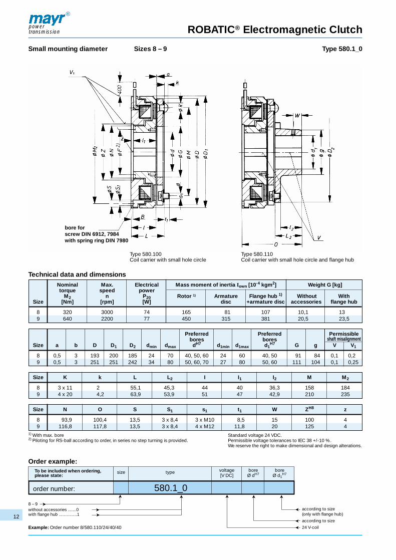
Small mounting diameter Sizes 8 – 9 Type 580.1_0
Technical data and dimensionsNominal Max. Electrical Mass moment of inertia Iown [10-4 kgm2] Weight G [kg]torque speed power
M2 n P20 Rotor 1) Armature Flange hub 1) Without WithSize [Nm] [rpm] [W] disc +armature disc accessories flange hub
8 320 3000 74 165 81 107 10,1 139 640 2200 77 450 315 381 20,5 23,5
Preferred Preferred Permissiblebores bores shaft misalignment
Size a b D D1 D2 dmin dmax dH7 d1min d1max d1H7 G g V V1
8 0,5 3 193 200 185 24 70 40, 50, 60 24 60 40, 50 91 84 0,1 0,29 0,5 3 251 251 242 34 80 50, 60, 70 27 80 50, 60 111 104 0,1 0,25
Size K k L L2 I I1 I2 M M2
8 3 x 11 2 55,1 45,3 44 40 36,3 158 1849 4 x 20 4,2 63,9 53,9 51 47 42,9 210 235
1) With max. bore Standard voltage 24 VDC.2) Piloting for RS-ball according to order, in series no step turning is provided. Permissible voltage tolerances to IEC 38 +/-10 %.
We reserve the right to make dimensional and design alterations.
Order example:To be included when ordering, size type voltage bore bore please state: [V DC] Ø dH7 Ø d1
H7
order number: 580.1_0
8 – 9 without accessories .......0 with flange hub ...............1
Example: Order number 8/580.110/24/40/40
according to size(only with flange hub)
according to size
24 V-coil
Size N O S S1 s1 t1 W ZH8 z
8 93,9 100,4 13,5 3 x 8,4 3 x M10 8,5 15 100 49 116,8 117,8 13,5 3 x 8,4 4 x M12 11,8 20 125 4
Type 580.100Coil carrier with small hole circle
Type 580.110Coil carrier with small hole circle and flange hub
➤ ➤
➤
➤➤
➤➤ ➤
➤
➤
➤
bore forscrew DIN 6912, 7984with spring ring DIN 7980
2)

ROBATIC® Electromagnetic Clutch
With coil carrier in bearing Sizes 3 – 9 Type 540.100540.102
powertransmission
®
13
Technical data and dimensionsNominal Max. Electrical Mass moment of inertia Weight torque speed power Iown [10-4 kgm2] G [kg]
Armature Rotor 2) Without With Pilot Preferreddisc accessories flange bores bores
M2 n P20 hubSize [Nm] [rpm] [W] a D D1 d2 d2 max d2
H7
3 10 8000 18 0,35 1,37 0,732 0,782 0,2 64,5 70 7 201) 10, 154 20 6000 19 1,05 3,35 1,22 1,29 0,2 81,5 87 8 251) 17, 205 45 5000 28 2,97 9,36 1,85 2,01 0,2 99 106 12 30 20, 25, 306 80 4200 38 7,04 20,8 3,16 3,38 0,3 118 125 12 40 20, 25, 307 160 3600 46 14 54,4 5,54 6,11 0,3 151 157 19 50 25, 30, 408 320 3000 61 81 178,0 11,6 12,86 0,5 193 200 22 60 40, 45, 509 640 2200 82 315 462,0 22,2 23,93 0,5 251 251 30 65 40, 50, 60
Size G K k L I6 M n1 O1 P p s1 t t1 U u V Y Y1
3 29,5 3 x 4,3 0,8 28 40 46 9 44 70 64 3 x M3 3,8 4,1 6 2 0,05 45° 30°4 30,5 3 x 4,6 1,7 31 43,5 60 9 48 79,7 72 3 x M4 4,3 5,0 8 2,5 0,05 45° 30°5 45,5 3 x 5,8 1,0 35,9 49 76 10 54,9 98,2 85 3 x M5 5,7 6,9 8 2,5 0,05 30° 22,5°6 48 3 x 7 1,0 40,5 55 95 10,5 62,0 115,4 105 3 x M6 6,7 6,7 10 2,5 0,05 30° 22,5°7 69 3 x 9,4 2,0 46,5 61,5 120 12 70,5 150,4 120 3 x M8 8,7 8,2 12 3 0,1 30° 15°8 91 3 x 11,5 2,0 55,4 74 158 13 85,1 189,4 145 3 x M10 10,6 8,5 14 4,5 0,1 30° 15°9 111 4 x 20 4,2 63,9 81 210 15,5 93,9 235,8 150 4 x M12 12,4 11,8 14 6 0,1 30° 15°
1) With max. bore keyway to DIN 6885/3 Standard voltage 24 VDC.2) With max. bore Permissible voltage tolerances to IEC 38 +/-10 %.
We reserve the right to make dimensional and design alterations.
Order example:To be included when ordering, size type voltage boreplease state: [V DC] Ød2
H7
order number: 540.1_ _
3 – 9 without accessories ............ 0 flange hub ........................... 1 power cable ........................ 0terminal ............................... 2
according to size
24 V-coil
Type 540.100With coil carrier in bearing
Type 540.102With coil carrier in bearing and terminal
➤ ➤
➤
➤➤
➤➤
➤ ➤➤
➤
➤
Example: Order number 5/540.100/24/20
permissibleshaft misalignment
groove for
friction support

KeySize eh6 L L7 I3 I8 M3 n1 n3 O5 P p s2 U u W1 X x Y1 Y2
3 56 28 25,8 35 21,5 66 9 16 70 70 64 3xM4 6 2 17,5 6x6x16 3,5 75° 90°4 64 31 29,7 454)/355) 24 75 9 17 78 79,7 72 3xM5 8 2,5 19 6x6x18 3,5 75° 90°5 75 35,9 38,7 506)/407) 30 94 10 19 94 98,2 85 3xM5 8 2,5 24,5 8x7x22 4 52,5° 90°6 90 40,5 43,5 606)/407)/209) 34 112 10,5 21,5 106 115,4 105 3xM6 10 2,5 28 10x8x25 5 52,5° 90°7 110 45,5 48,9 558)/359)/_11) 39 145 12 24 120 150,4 120 3xM6 12 3 31 10x8x28 5 45° 90°8 135 55,4 53,9 758)/559)/2511) 44 184 13 30 140 189,4 145 3xM8 14 4,5 36 14x9x32 5,5 45° 90°9 160 63,9 57,1 7010)/4011)/_12) 46 235 15,5 30 152 235,8 150 3xM8 14 6 38 16x10x36 6 45° 135°
ROBATIC® Electromagnetic Clutch
With flange in bearing3) Sizes 3 – 9 Type 540.14_
powertransmission
®
14
Technical data and dimensionsNominal Max. Electrical Max. Max. Mass moment of inertia Weighttorque speed power admissible admissible Iown[10-4 kgm2] with max.
M2 P20 friction friction Rotor Armature borework with PRperm with max. disc + Typean unique bore driving 540.140
switching WRperm Type flangeSize [Nm] [rpm] [W] [J] [ J
sec] 540.140 [kg] a D1 D3 d3 d4max
3 10 8000 18 3,8x10³ 67 1,59 1,97 1,2 0,2 70 71 16 154 20 6000 19 6,2x10³ 89 3,82 4,06 1,85 0,2 87 82 20 191)
5 45 5000 28 9x10³ 110 10,24 9,95 2,95 0,2 106 102 26 246 80 4200 38 15x103 125 23,22 22,93 4,7 0,3 125 122 266)/377) 337 160 3600 46 25x103 167 62,05 50,53 8,25 0,3 157 156 378)/479)_11) 468 320 3000 61 42x103 222 197,66 174,83 16,6 0,5 200 199 378)/479)/5911) 589 640 2200 82 65x103 280 497 533,7 29,2 0,5 251 250 4710)/6711)/_12) 65
1) Above Ø 18 keyway to DIN 6885/3 with 4) Above Ø d4 to 14 9) Above Ø d4 over 28 Standard voltage 24 VDC.d4max - depth of hub keyway 1,2+0,1 5) Above Ø d4 over 14 10) Above Ø d4 to 38 Permissible voltage tolerances to
3) 2-shaft connection on request 6) Above Ø d4 to 19 11) Above Ø d4 over 38 IEC 38 +/- 10 %.7) Above Ø d4 over 19 12) Above Ø d4 over 55 We reserve the right to make dimensional8) Above Ø d4 to 28 and design alterations.
Order example:To be included when ordering, size type voltage bore *counterboreplease state: [V DC] Ø d4 by choice
order number: 540.14 _ AS or AÜ
3 – 9 power cable ............... 0terminal ....................... 2
Example: Order number 5/540.140/24/24/AS
AS ... counterboreat coil carrier side
AÜ ...counterboreat transmission flange side
according to size
24 V-coil
Type 540.140With flange in bearing
➤ ➤
➤➤➤
➤➤ ➤
➤
➤
➤
➤
groove for key „x“
groove for
friction support

Size 3 4 5 6 7 8 9
a 0,2+0,1 0,2+0,15 0,2+0,15 0,3+0,15 0,3+0,15 0,5+0,15 0,5+0,15-0,05 -0,05 -0,05 -0,05 -0,05 -0,1 -0,1
e 0,25 0,3 0,3 0,35 0,5 0,55 0,6
Technical Explanations
Mounting tolerances
powertransmission
®
15
Table for the adjustment of the air gaps Table concerning the admissible shaft displacement
Fig. 1 Fig. 2
Size 3 4 5 6 7 8 9
V 0,05 0,05 0,05 0,05 0,1 0,1 0,1
Table 1
The dimension „a“ (Fig. 1) is to be adjusted according to the table 1.Care must be taken to ensure that the shaft is fastened axially,since, otherwise the dimension „a“ will change and cause therotor to brush against the armature disc or the coil carrier. The airgap „e“ is chosen, that a banding of the rotor at the coil carrier isnot possible when keeping the permissible center deviations Vand V1 (see table technical data).
Construction:ROBATIC®-Electromagnetic clutches are manufactured to IP 54specification and the insulation class F to 155 °C for coil, moulding compound and power cable as well as insulation classB 130 °C for the magnet coil plastic-extrusion-coated. The friction linings are asbestos free, the surface of coil carrier, rotorand flange hub are phosphated. The armature disc is nitrited andthe transmitting spring is made of stainless steel. The drive elements should be made of magnetically poor transmittingmaterial to avoid magnetic field losses and subsequent powerreduction.
ROBATIC® clutches are used for dry running. The torque is transmitted by connection of the armature disc on the iron polesand friction lining of the rotor.
When coupling two shafts the eccentricity „V“ of the shafts according to table 2 must not be exceeded. The larger the displacement „V“ the greater the friction surface becomes. In thecase of this arrangement care must be taken that both shaftshave no axial play since, otherwise, a brushing of the rotor wouldalso be possible. The flange hub is kept axially by means of a setscrew (set at 90 ° to the key). The „V“-values are indicated againin the technical data of the individual clutches.
Table 2
Please note:The running-in instructions or min. speed are to be observed (seepage 3).
The friction surfaces have to be absolutely free of oil and grease,otherwise, the torque drops significantly. The air gap „a“ (Fig. 1)has to be checked periodically. The clutch does not function correctly, if the max. working air gap is exceeded (see table 1,page 18).
Assembly and maintenance should be made by well trained specialists.

powertransmission
®
16
Technical Explanations
Clutch size calculation
Formulae:
1. Drive torque
MA = 9550 · PA [Nm]n
2. Required torque
Mreq. ≥ K · MA [Nm]
3. Switchable torque of the clutch(acc. to fig. 1, page 17)
MS ≥ Mreq. [Nm]
4. Mass moment of inertia
I = Iown + Iadd. [kgm2]
5. Acceleration torque of the clutch
Ma = MS –(+) ML [Nm]
6. Acceleration time
ta = I · n + t1 cl [sec]9,55 · Ma
7. Max. switching frequency per hour (dependent on time)
Sh max = 1 · 3600 [h-1]tvM + (ta + t2 cl) · 1,2
8. Friction work per acceleration
Qa = I · n2· Ms [J]
182,4 Ma
9. Examination of the selected clutch size in fig. 2 (page 17,friction power diagram). Intersection friction work ÷switching frequency must be below the friction powercurve! If it is above, the next size has to be selected andre-calculated from point 3 on.
Qa < QE [J]
10. Number of switchings until adjustment
Zn = Q1 · (an - a) [-]Qa
11. Number of switchings until end of wear
Z = Qtot [-]Qa
Designation
PA [kW] = drive power
MA [Nm] = drive torque
Ma [Nm] = acceleration torque of the clutch
Mreq. [Nm] = required torque
ML [Nm] = load torque (+ = drop load) (- = lift load)
MS [Nm] = switchable torque of the clutch(acc. to fig. 1, page 17)
n [rpm] = drive speed
K = safety factor >= 2
I [kgm2] = mass moment of inertia
Iown. [kgm2] = mass moment of inertia (acc. to table of dimension)
Iadd. [kgm2] = additional mass moment of inertia
ta [sec] = acceleration time
tvM [sec] = braking time of the machine
t1 Ku [sec] = switch-on time of the clutch } acc. to table 1,
t2 Ku [sec] = switch-off time of the clutch page 18
Sh max [h-1] = max. switching frequency per hour
(dependent on time)
Qtot. [J] = total friction work (acc. to table 1, page 18)
Qa [J] = total friction work per acceleration
QE [J] = perm. friction work with an unique switching } acc. to table 1,
Q1 [J/max] = friction work until 1 mm wear page 18
Zn = number of switchings until re-adjustment
Z = number of switchings until end of wear
a [mm] = nominal air gap } acc. to table 1,
an [mm] = max. working air gap page 18

powertransmission
®
17
Technical Explanations
Calculation example:Data
Input power PA = 3 kW
Input speed n = 1400 rpm
Load torque output ML = 15 Nm
Additional mass moment of inertia Iadd. = 0,15 kgm2
Braking time of the machine tv M = 1,5 [sec]
180 switchings per hour
Input torque
MA = 9550 · PA = 9550 · 3 = 20,5 [Nm]n 1400
Required torque
Mreq. = K · MA = 2 · 20,5 = 41 [Nm]
Determined clutch size (acc. to fig. 1) = size 6
MS ≥ Mreq. = 47 [Nm]
Selected clutch = size 6 type 500.200.0
Mass moment of inertia
I = Iown + Iadd. = 0,001756 + 0,15 = 0,151756 [kgm2]
Acceleration torque of the clutch
Ma = MS – ML = 47 - 15 = 32 [Nm]
Acceleration time of the clutch
ta = I · n + t1*Cl = 0,151756 · 1400
+ 0,15 = 0,845 [sec]9,55 · Ma 9,55 · 32
* Switching times t1 Cl and t2 Cl from table 1, page 18 = without overexcitation
Max. switching frequency per hour
Sh max = 1 · 3600 tvM + (ta + t2*Cl) · 1,2
Sh max = 1 · 3600 = 1392 [h-1]1,5 + (0,845 + 0,060) · 1,2
Friction work per acceleration
Qa = I · n2· Ms = 0,151756 · 14002
· 47 = 2395 [J] <= QE182,4 Ma 182,4 32
Switching frequency acc. to fig. 2 = 180 switchings per hour = permissible
(The point of intersection determined in fig. 2 must be located in orunder the characteristic of the selected clutch)
Number of switchings until adjustment
Zn = Q1 · (an - a) = 57 · 107
· (1,2 - 0,3) = 214196 switchingsQa 2395
Number of switchings until wear limit
Z = Qtot = 100 · 107
= 417536 switchingsQa 2395
Friction power diagramvalid for speed = 1500 rpm
Fig. 1
Fig. 2
Switching frequency Sh [h-1]
Qa
Sw
itch
ing
wo
rk [
J]S
wit
chab
le t
orq
ue M
S[N
m]
Switchable torque
Speed n [rpm]ca
lcul
atio
n ex
amp
le
calc
ulat
ion
exam
ple
Size 9
Size 8
Size 3
Size 4
Size 5Size 6
Size 7
Size 9
Size 8
Size 3
Size 4
Size 5
Size 6
Size 7

powertransmission
®
18
Technical Explanations
Clutch size 3 4 5 6 7 8 9
Without t11 cl 0,010 0,015 0,020 0,030 0,045 0,050 0,060over- t1 cl 0,045 0,065 0,080 0,150 0,200 0,350 0,400Switching
Type excitation t2 cl 0,012 0,020 0,045 0,060 0,090 0,095 0,130times500.___._
With over- t11 cl 0,003 0,005 0,007 0,010 0,015 0,020 0,035[sec]excitation t1 cl 0,025 0,035 0,040 0,075 0,100 0,170 0,235
Without t11 cl 0,010 0,012 0,012 0,020 0,025 0,050 0,060over- t1 cl 0,050 0,072 0,112 0,160 0,200 0,350 0,460Switching
Type excitation t2 cl 0,014 0,020 0,030 0,050 0,075 0,095 0,130times540.___._
With over- t11 cl 0,004 0,005 0,006 0,010 0,013 0,020 0,035[sec]excitation t1 cl 0,024 0,035 0,056 0,080 0,100 0,170 0,235
Permissible friction work with a single switching QE [J] 3,8 · 103 6,2 · 103 9 · 103 15 · 103 25 · 103 42 · 103 65 · 103
Friction Type
work up to 500.___._12,5 · 107 20 · 107 33 · 107 57 · 107 100 · 107 105 · 107 170 · 107
1 mm wear TypeQ1 [J/mm] 540.___
8,8 · 107 13,4 · 107 24 · 107 36 · 107 60 · 107 105 · 107 170 · 107
Total frictionType
work 500.___._12,5 · 107 25 · 107 50 · 107 100 · 107 200 · 107 185 · 107 340 · 107
Qtot [J] Type540.___._
8 · 107 16 · 107 35 · 107 68 · 107 135 · 107 185 · 107 340 · 107
Nominal air gap a [mm] 0,2 0,2 0,2 0,3 0,3 0,5 0,5
Max. working air gap an [mm] 0,6 0,8 1,0 1,2 1,5 1,8 2,0
Switching times:The switching times given in table 1 have been determined bycomprehensive series of tests. They are valid for switching onthe D.C. side with nominal air gap and warm coil.
Deviations depend on the corresponding overall situation,environmental temperatures, release path and the type ofrectification with which the corresponding clutch is operated.
Table 1
M2 = nominal torque of the clutch ta = acceleration time t1 = connection time t3 = slipping timeML = load torque of the drive t11 = deceleration time for connection t2 = disconnection time
Fig. 3
2
2
time
time
Exc
itat
ion
(vo
ltag
e)
Wear values NoteWear values can only be recommended values due to the operating parameters as for example: sliding speed, pressure ortemperature.
Off
On

powertransmission
®
19
ROBA®-quick Electromagnetic Brakes
The positioning accuracyfor the whole service life
Exact positioning until limit of wearideal for positioning operations.
Large internal diameters ofthe magnetic coil bodiesTherefore large permissible shaft diameters and few magnetic field losses.
High torque securitydue to an optimised magnetic field and new design of the ROBA®-quick. Therefore higher capacities due to fewmagnetic field losses.
Short switchingtimes/high switching frequency
Low noise

powertransmission
®
20
ROBA®-quick Electromagnetic Brakes
FunctionROBA®-quick are „energise to engage“, electromagnetic poleface brakes. If a DC voltage is applied to the magnetic coil (1)a magnetic field is formed, and the armature disc (3) is attracted to the coil carrier with friction lining (4). The braketorque runs from the coil carrier (2) via friction lining (4), armature disc (3) and membrane transmitting spring (5) to theflange and the shaft.
If the magnetic coil is de-energised the membrane transmitting spring (5) draws the armature disc (3) back to theflange (6). The brake is released and the shaft (7) can run freely.
ROBA®-quickStandardPage 21
ROBA®-quickSmall mounting diameterPage 23
Technical explanationsPage 24
Electrical accessoriesPage 37
wear, air gapmax.
wear, air gapmax.
previouselectro-magneticbrakes
adjustinginterval
adjusting intervalnumber ofswitchings
number ofswitchings

powertransmission
®
21
ROBA®-quick Electromagnetic Brakes
Standard Sizes 3 – 7 Type 520.200.0520.201.0520.202.0
Technical data and dimensionsNominal Max. Electrical Mass moment of Weight Pilot Preferredtorque Speed power inertia G [kg] bores bores
Iown [10-4 kgm2]Flange Without With
M2 n P20 Armature hub 2)+ accesso- flangeSize [Nm] [rpm] [W] disc armature disc ries hub a b D D2 d1 d1max d1
H7
3 8,5 8600 13 0,76 1,02 0,38 0,42 0,2 4,5 73,5 70 8 20 17, 204 17 7000 20 1,92 2,75 0,55 0,86 0,2 4 92 88 12 30 20, 255 45 6100 31 6,86 8,63 1,25 1,40 0,2 5,5 115 110 14 35 1) 25, 306 80 5800 47 17,56 24,66 1,88 2,35 0,3 5,5 140 140 19 45 30, 407 160 4500 71 52,86 70,63 3,5 7,5 0,3 7,5 177 170 22 60 40, 50
Size G g Hh9 K k L1 L2 I1 I2 M M1 n2 O1 O2 s s1 t t1 V
3 36 29,5 80 3x4,6 1,6 22,1 20 3,5 16 60 72 2,6 42,1 26,1 4 x 4,8 3 x M4 3,9 5,0 0,054 49 44 100 3x6,4 1,7 24,7 22 4,3 17 76 90 3,2 46,7 29,7 4 x 5,7 3 x M5 4,5 6,9 0,055 57,5 47 125 3x 7 1,7 28,1 28 5,2 22 95 112 1,1 56,1 34,1 4 x 6,8 3 x M6 5,9 8,7 0,056 74 66 150 3x10,4 2,2 31,4 32 6 25 120 137 0,2 63,5 38,5 4 x 6,8 3 x M8 7,1 6,6 0,057 95 84 190 3x10,2 2,7 34,7 36 7 27 150 175 1,4 70,7 43,7 4 x 9,2 3 x M8 8,1 10,1 0,10
1) Up to Ø 32 keyway to DIN 6885/1, over Ø 32 keyway to DIN 6885/3 Standard voltages 24 VDC; 104 VDC.2) With max. bore Permissible voltage tolerances to IEC 38 +/-10 %.
We reserve the right to make dimensional and design alterations.
Order example:To be included when ordering, size type voltage boreplease state: [V DC] Ø d1
H7 3)
order number: 520.20 _.03 – 7 without accessories......0 flange hub ....................1 internal hub .................2 3) indication only with flange hub design or internal hub.
Example: Order number 5/520.202.0/24/30
according to size
24; 104 V-coils
V1 W ZH8 z
0,1 5 42 3,50,15 5 52 4,50,15 6 62 50,15 8 80 60,20 8 100 6
Type 520.200.0Standard
Type 520.201.0Standard with flange hub
Type 520.202.0Standard with internal hub
➤ ➤
➤
➤➤➤
➤➤
➤
➤
cable length: 400 mmdisplacedto bores by 45°
rectifier
mains ~

ROBA®-quick Electromagnetic Brakes
Standard Sizes 8 – 9 Type 520.100520.110520.120
powertransmission
®
22
Technical data and dimensionsNominal Max. Electrical Mass moment of Weight torque speed power inertia G [kg] Pilot Preferred
Iown [10-4 kgm2] bores boresFlange Without With
M2 n P20 Armature hub 2)+ accesso- flangeSize [Nm] [rpm] [W] disc armature disc ries hub a b D D2 d1 d1max d1
H7 f
8 320 3000 40 81 107 5,64 13,9 0,5 16 193 185 22 60 40, 50 929 640 2200 77 315 381 6,90 15,63 0,5 16 251 242 25 80 50, 60 112
Size G g Hh9 K k L2 L6 I2 I4 I7 M M1 n2 O2 O3 s s1 t1 V
8 91 84 230 3x11,5 2 45,3 40,1 36,3 5 30 158 215 0,8 86,4 50,1 4x9 3xM10 8,5 0,19 111 104 290 4x20 4,2 53,9 47,9 42,9 6 35 210 270 1,0 101,8 58,9 4x11 4xM12 11,8 0,1
2) With max. bore Standard voltage 24 VDC.Permissible voltage tolerances to IEC 38 +/-10 %.We reserve the right to make dimensional and design alterations.
Order example:To be included when ordering, size type voltage boreplease state: [V DC] Ø d1
H7 3)
order number: 520.1 _08 – 9 without accessories.....0flange hub ...................1 internal hub ................2 3) indication only with flange hub design or internal hub.
Example: Order number 8/520.110/24/40
according to size
24 V-coil
V1 W ZH8 z
0,2 15 100 40,25 20 125 4
➤ ➤
➤
➤➤➤
➤➤
➤
➤
Type 520.100Standard brake
Type 520.110Standard with flange hub
Type 520.120Standard with internal hub
Cable length
shaft misalignment
*) observe run-in instructions or minimum speed (see page 3).

ROBA®-quick Electromagnetic Brakes
Small mounting diameter Sizes 3 – 7 Type 520.210.0520.211.0520.212.0
powertransmission
®
23
Technical data and dimensionsNominal Max. Electrical Mass moment of Weight torque speed power inertia G [kg] Pilot Preferred
Iown [10-4 kgm2] bores boresFlange Without With
M2 n P20 Armature hub 2)+ accesso- flangeSize [Nm] [rpm] [W] disc armature disc ries hub a b D D2 d1 d1 max d1
H7
3 8,5 8600 13 0,7 0,8 0,35 0,40 0,2 4,5 73,5 54 7 17 10, 154 17 7000 20 1,79 1,97 0,58 0,65 0,2 4 92 70 8 20 17, 205 45 6100 31 6,28 7,19 1,2 1,35 0,2 5,5 115 88 12 30 20,256 80 5800 47 15,77 17,54 1,80 2,0 0,3 5,5 140 110 14 35 1) 25, 307 160 4500 71 48,1 55,2 3,3 3,85 0,3 7,5 177 140 19 45 30, 40
Size G g Hh9 K k L1 L2 I1 I2 M M1 n2 O1 O2 s s1 t t1 V
3 36 27 80 3x4,3 1,6 22,1 15 3,5 11,5 46 72 8,5 37,1 25,6 4x4,5 3xM3 3,9 4,0 0,054 49 29,5 100 3x4,6 1,7 24,6 20 4,3 16 60 90 6,1 44,6 28,6 4x5,7 3xM4 4,4 5,0 0,055 57,5 44 125 3x6,4 2,3 28,1 22 5,2 17 76 112 7,9 50,1 33,1 4x6,8 3xM5 5,8 6,8 0,056 74 47 150 3x7 2,7 31,3 28 6 22 95 137 5,5 59,3 37 4x6,8 3xM6 7,0 8,5 0,057 95 66 190 3x10,4 2,7 34,4 32 7 25 120 175 5,7 66,5 41,5 4x9,2 3xM8 8,1 8,1 0,10
1) Up to Ø 32 keyway to DIN 6885/1, above Ø 32 keyway to DIN 6885/3 Standard voltages 24 VDC; 104 VDC.2) With max. bore Permissible voltage tolerances to IEC 38 +/-10 %.
We reserve the right to make dimensional and design alterations.
Order example:To be included when ordering, size type voltage boreplease state: [V DC] Ø d1
H7 3)
order number: 520.21 _.03 – 7 without accessories...0 flange hub .................1 internal hub ..............2 3) indication only with flange hub design or internal hub.
Example: Order number 5/520.212.0/24/25
according to size
24; 104 V-coils
V1 W ZH8 z
0,1 5 35 20,15 5 42 2,50,15 6 52 30,15 8 62 3,50,20 8 80 3,5
Type 520.210.0Small mounting diameter
Type 520.211.0Small mounting diameterand flange hub
Type 520.212.0Small mounting diameter and internal hub
➤ ➤
➤
➤➤➤
➤➤
➤
➤
permissible shaft misalignment
cable length: 400 mmdisplacedto bores by45° rectifier
mains ~

powertransmission
®
24
Size 3 4 5 6 7 8 9
a 0,2+0,1 0,2+0,15 0,2+0,15 0,3+0,15 0,3+0,15 0,5+0,15 0,5+0,15-0,05 -0,05 -0,05 -0,05 -0,05 -0,1 -0,1
Technical Explanations
Mounting tolerances
Table for the adjustment of the air gaps Allowable shaft displacement
Fig. 1 Fig. 2
Size 3 4 5 6 7 8 9
V 0,05 0,05 0,05 0,05 0,1 0,1 0,1
Table 1
The dimension „a“ (Fig. 1) is to be adjusted according to thetable 1. Care must be taken to ensure that the shaft isfastened axially, since otherwise the dimension „a“ will change and cause the armature disc to band against coil carrier.
Construction:ROBA®-quick Electromagnetic brakes are manufactured to IP 54 specification and the insulation class F to 155 °C for coil,moulding compound and power cables as well as insulationclass B 130 °C for the magnetic coil plastic extrusion-coated.The friction linings are asbestos free, the surface of coil carrier and flange hub are phosphated. The armature disc isnitrated and the membrane spring is made of stainless steel.
ROBA®-quick brakes are used for dry running. The torque istransmitted by friction between armature disc and the ironpoles and friction lining surface of the coil carrier.
When braking the eccentricity „V“ according to table 2 mustnot be exceeded. The larger the displacement „V“ the morethe torque decreases and the hotter the friction surface becomes. In the case of arrangement according to table 2care must be taken that the coil carrier and shaft have no axial play, since otherwise a brushing of the coil carrier wouldbe possible. The flange hub is kept axially by means of a setscrew (set at 90° to the key). The „V“-values are indicatedagain in the technical data of the individual brakes.
Table 2
Please note:The running-in instructions or min. speed are to be observed(see page 3).
The friction surfaces have to be absolutely free of oil and grease as otherwise the torque drops significantly. The air gap„a“ (Fig. 1) has to be checked periodically. The brake does notfunction correctly if the max. working air gap (see table 1,page 27) is exceeded.
Assembly and maintenance have to be made by well-trainedspecialists.

powertransmission
®
25
Technical Explanations
Brake size calculation
Formulae:
1. Drive torque
MA = 9550 · PA [Nm]n
2. Required torque
Mreq. ≥ K · MA [Nm]
3. Switchable torque of the brake(acc. to fig. 1, page 26)
MS ≥ Mreq. [Nm]
4. Mass moment of inertia
I = Iown. + Iadd. [kgm2]
5. Deceleration torque of the brake
Mv = MS –(+) ML [Nm]
6. Deceleration time
tv = I · n + t1 Br [sec]9,55 · Mv
7. Max. switching frequency per hour (dependent on time)
Sh max = 1 · 3600 [h-1]taM + (tv + t2 Br) · 1,2
8. Friction work per deceleration
Qv = I · n2· Ms [J]
182,4 Mv
9. Examination of the selected brake size in fig. 2 (page 26,friction power diagram). Intersection friction work ÷switching frequency must be below the friction powercurve! If it is above, the next size has to be selected andre-calculated from point 3 on.
Qv < QE [J]
10. Number of switchings until adjustment.
Zn = Q1 · (an - a) [-]Qa
11. Number of switchings until end of wear.
Z = Qtot [-]Qv
Designation
PA [kW] = drive power
MA [Nm] = drive torque
Mreq. [Nm] = required torque
ML [Nm] = load torque (+ = drop load) (- = lift load)
MS [Nm] = switchable torque of the brake(acc. to fig. 1, page 27)
Mv [Nm] = deceleration torque of the brake
n [rpm] = drive speed
K = safety factor clutch >= 2
I [kgm2] = mass moment of inertia
Iown [kgm2] = own mass moment of inertia (acc. to table of dimensions)
Iadd. [kgm2] = additional mass moment of inertia
tv [sec] = deceleration time
taM [sec] = acceleration time of the machine
t1 Br [sec] = switch-on time of the brake } acc. to table 1
t2 Br [sec] = switch-off time of the brake page 27
Sh max [h-1] = max. switching frequency per hour (dependent on time)
Qtot. [J] = total friction work (acc. to table 1, page 27)
Qv [J] = friction work per deceleration
QE [J] = perm. friction work with an unique switching} acc. to table 1
Q1 [J/max] = friction work until 1 mm wear page 27
Zn = number of switchings until re-adjustment
Z = number of switchings until end of wear
a [mm] = nominal air gap } acc. to table 1
an [mm] = max. working air gap page 27

powertransmission
®
26
Technical Explanations
Calculation example:Data
Input power PA = 3 kW
Input speed n = 1400 rpm
Load torque output ML = 15 Nm
Additional mass moment of inertia Iadd. = 0,15 kgm2
Acceleration time of the machine ta M = 1,5 [sec]
350 switchings per hour
Input torque
MA = 9550 · PA = 9550 · 3 = 20,5 [Nm]n 1400
Required torque
Mreq. = K · MA = 2 · 20,5 = 41 [Nm]
Determined brake size (acc. to fig. 1) = size 6
MS ≥ Mreq. = 47 [Nm]
Selected brake = size 6 type 500.200.0
Mass moment of inertia
I = Iown + Iadd. = 0,001756 + 0,15 = 0,151756 [kgm2]
Deceleration torque of the brake
Mv = MS + ML = 47 + 15 = 62 [Nm]
Deceleration time of the brake
tv = I · n + t1* Br = 0,151756 · 1400
+ 0,10 = 0,46 [sec]9,55 · Mv 9,55 · 62
* Switching times t1 Br and t2 Br from table 1, page 27 = without overexcitation
Max. switching frequency per hour
Sh max = 1 · 3600 taM + (tv + t2*Br) · 1,2
Sh max = 1 · 3600 = 1695 [h-1]1,5 + (0,46 + 0,060) · 1,2
Friction work per deceleration
Qv = I · n2· Ms = 0,151756 · 14002
· 47 = 1236 [J] <= QE182,4 Mv 182,4 62
* Switching frequency acc. to fig. 2 = 350 switchings per hour = permissible
(The point of intersection determined in fig. 2 must be located in orunder the characteristic of the selected brake)
Number of switchings until adjustment
Zn = Q1 · (an - a) = 57 · 107
· (1,2 - 0,3) = 415 048 switchingsQv 1236
Number of switchings until wear limit
Z = Qtot = 100 · 107
= 809 061 switchingsQv 1236
Friction power diagramvalid for speed = 1500 rpm
Fig. 1
Fig. 2
Sw
itch
able
to
rque
MS
[Nm
]
Switchable torque
Speed n [rpm]
Size 9
Size 8
Size 7
Size 6
Size 5
Size 4
Size 3
QV
Sw
itch
ing
wo
rk [
J]
Switching frequency Sh [h-1]
Size 9
Size 8
Size 7
Size 6
Size 5
Size 4
Size 3
calc
ulat
ion
exam
ple
calc
ulat
ion
exam
ple

powertransmission
®
27
Technical Explanations
Brake size 3 4 5 6 7 8 9
Without t11 Br 0,006 0,008 0,010 0,015 0,025 0,027 0,030over- t1 Br 0,035 0,040 0,055 0,100 0,150 0,245 0,330Switching
Type excitation t2 Br 0,010 0,018 0,030 0,060 0,090 0,100 0,140times520.___._
With over- t11 Br 0,002 0,003 0,004 0,006 0,008 0,010 0,015[sec]excitation t1 Br 0,020 0,022 0,030 0,050 0,075 0,120 0,165
Permissible friction work with a single switching QE [J] 3,8 · 103 6,2 · 103 9 · 103 15 · 103 25 · 103 42 · 103 65 · 103
Frictionwork up to Type 12,5 · 107 20 · 107 33 · 107 57 · 107 100 · 107 105 · 107 170 · 107
1mm wear 520.___._Q1 [J/mm]
Total frictionTypework
520.___._12,5 · 107 25 · 107 50 · 107 100 · 107 200 · 107 185 · 107 340 · 107
Qtot [J]
Nominal air gap a [mm] 0,2 0,2 0,2 0,3 0,3 0,5 0,5
Max. working air gap an [mm] 0,6 0,8 1,0 1,2 1,5 1,8 2,0
Switching times:The switching times given in table 1 have been determined bycomprehensive series of tests. They are valid for switching onthe D.C. side with nominal air gap and warm coil.
Deviations depend on the corresponding overall situation,environmental temperatures, release path and the type of rectification with which the corresponding clutch is operated.
Table 1
M2 = nominal torque of the brake tv = deceleration time t1 = connection time t3 = slipping timeML = load torque of the drive t11 = deceleration time for connection t2 = disconnection time
Fig. 3
time t
time t
On
OffExc
itat
ion
(vo
ltag
e)
Wear values NoteWear values can only be recommended values due to the operating parameters as for example: sliding speed, pressure ortemperature.
powertransmission
®
28
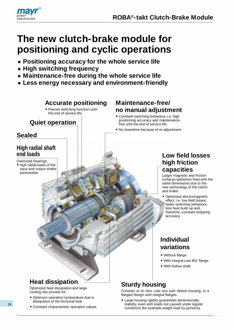
ROBA®-takt Clutch-Brake Module
Sealed
High radial shaftend loadsOversized bearings� high radial loads of the
input and output shaftspermissible.
The new clutch-brake module for positioning and cyclic operations� Positioning accuracy for the whole service life� High switching frequency� Maintenance-free during the whole service life� Less energy necessary and environment-friendly
Accurate positioning� Precise switching function until
the end of service life.
Maintenance-free/no manual adjustment� Constant switching behaviour, i.e. high
positioning accuracy and maintenance-free until the end of service life.
� No downtime because of re-adjustment.
Low field losseshigh frictioncapacitiesLarger magnetic and frictionsurfaces (asbestos free) with thesame dimensions due to thenew technology of the clutchand brake.
� Optimised electromagneticeffect, i.e. low field losses,faster switching behaviour,less heat build up and,therefore, constant stoppingaccuracy.
Quiet operation
Individualvariations� Without flange
� With integral cast IEC-flange
� With hollow shaft
Heat dissipationOptimized heat dissipation and large cooling ribs provide for:
� Optimum operation temperature due todissipation of the frictional heat.
� Constant characteristic operation values.
Sturdy housingConsists of en bloc cast two part ribbed housing, in aflanged design with integral flanges.
� Large housing rigidity guarantees dimensionally stability, even with loads not caused under regularconditions (for example weight load by persons).

powertransmission
®
29
ROBA®-takt Clutch-Brake Module
OUTPUT INPUTBRAKE CLUTCH OUTPUT INPUT
without flange/ without flange/ Type-No.: 674.0_4.0
shaft shaft Page 30
without flange/ IEC-flange/ Type-No.: 674.0_5.0
shaft hollow shaft Page 31
IEC-flange/ without flange/ Type-No.: 675.0_4.0
shaft shaft Page 32
IEC-flange/ IEC-flange/ Type-No.: 675.0_5.0
shaft hollow shaft Page 33
Structural Components
Further structural components are available on request
Technical explanations Page 34
Electronic accessories Page 37
6
6
66

powertransmission
®
30
Type 674.0_4.0
ROBA®-takt
Technical data and dimensionsNominal torque Electrical power Speed Weight Inertia I
Clutch Brake Clutch Brake max. kg output[10-4 kgm2]
M2 P20 P20 n Type TypeSize [Nm] [W] [W] [rpm] 674.014.0 674.014.0
3 10 8,5 17 13 3600 3,9 2,5
4 20 17 25 23 3600 6,8 6,37
5 45 45 30 30 3600 9,9 21,5
6 80 80 44 45 3600 15,3 60,5
7 160 160 79 70 3600 27,7 138
Size A B B1 B2 c c1 dk6 f H H1 i k L L1 I r u
3 126 75 93 114 19 37 14 1 86 63 M5 12,5 200 138 30 6,6 3
4 146 95 115 127 22 46,5 19 1 94 80 M6 16 239 157 40 9 3
5 165 110 136 156 28 57 24 1 106 90 M8 19 279 177 50 11 4
6 189 120 152 179 28 67 28 1 121 100 M10 22 323 201 60 11 4
7 230 145 175 230 33 89 38 1 142 132 M12 28 408 246 80 14 5
Standard voltages 24 VDC; 104 VDC.Permissible voltage tolerances to IEC 38 +/-10 %.We reserve the right to make dimensional and design alterations.
Order example:To be included when ordering, output inputplease state: size type voltage shaft shaft with
[V DC] Ø dk6 Ø dk6switch gear
order number: 674.0_4.0 W W see pages 37-38
3 – 7 without feet ..............0 with feet....................1
according to table(special dimension on request)
24; 104 V-coils
Example: Order number 5/674.014.0/24V/W24/W24
➤ ➤
➤
➤➤
➤ ➤➤
➤
➤
output brake side
input clutch side

ROBA®-takt powertransmission
®
31
Type 674.0_ _.0
Technical data and dimensionsNominal torque Electrical power Speed Weight Inertia Small or IEC-dimensions
Clutch Brake Clutch Brake max. [kg] I largeoutput IEC-flange
[10-4 kgm2] to choiceM2 P20 P20 n Type Type
Size [Nm] [W] [W] [rpm] 674.014.0 674.014.0 D d1F8 b+03
+05e1 f1
3 10 8,5 17 13 3600 3,9 2,5IEC-small 140 11 95 115 3,5IEC-large 160 14 110 130 4
4 20 17 25 23 3600 6,8 6,37IEC-small 160 14 110 130 4IEC-large 200 19 130 165 4
5 45 45 30 30 3600 9,9 21,5IEC-small 200 19 130 165 4IEC-large 200 24 130 165 4
6 80 80 44 45 3600 15,3 60,5IEC-small 200 24 130 165 4IEC-large 250 28 180 215 4,5
7 160 160 79 70 3600 27,7 138IEC-small 250 28 180 215 4,5IEC-large 300 38 230 265 4,5
Small or IEC-large dimensions
IEC-flangeSize to choice H1
1) I1 s1 A B B1 c c1 dk6 f H H21) i k L L1 l p
3IEC-small 70 25 9
110 75 93 19 11 14 1 86 63 M5 12,5 170 139 30 12IEC-large 80 32 9
4IEC-small 80 32 9
126 95 115 22 13,5 19 1 94 80 M6 16 199 158 40 13IEC-large 100 42 11
5IEC-small 100 42 11
140 110 136 28 18 24 1 106 90 M8 19 229 178 50 14IEC-large 100 55 11
6IEC-small 100 55 11
164 120 152 28 18 28 1 121 100 M10 22 263 202 60 14IEC-large 125 65 14
7IEC-small 125 65 14
198 145 175 33 21 38 1 142 132 M12 28 328 247 80 20IEC-large 150 90 14
1) Note difference in height of feet on driver and driven sides Standard voltages 24 VDC; 104 VDC.Permissible voltage tolerances to IEC 38 +/-10 %.We reserve the right to make dimensional and design alterations.Order example:
To be included when ordering, output input please state: size type voltage shaft shaft with
[V DC] Ø dk6 Ø d1F8 switch gear
order number: 674.0__.0 W B see pages 37-38
3 – 7
without feet ............0 with feet .................1
according to table (special dimension on request)
24; 104 V-coilsclutch side:
5 IEC-flange small6 IEC-flange largeExample: Order number 4/674.015.0/24V/W19/B24
r u
6,6 3
9 3
11 4
11 4
14 5
➤ ➤
➤
➤➤
➤ ➤ ➤➤
➤
➤
➤➤
output brake side
input clutch side

Nominal torque Electrical power Speed Weight Inertia Small or IEC-dimensionsClutch Brake Clutch Brake max. [kg] I large
output: IEC-flange[10-4 kgm2] to
M2 P20 P20 n Type Type choiceSize [Nm] [W] [W] [rpm] 674.014.0 674.014.0 D dk6 bj6 e f H1
1) i
3 10 8,5 17 13 3600 3,9 2,5IEC-small 140 11 95 115 3 70 M4IEC-large 160 14 110 130 3,5 80 M5
4 20 17 25 23 3600 6,8 6,37IEC-small 160 14 110 130 3,5 80 M5IEC-large 200 19 130 165 3,5 100 M6
5 45 45 30 30 3600 9,9 21,5IEC-small 200 19 130 165 3,5 100 M6IEC-large 200 24 130 165 3,5 100 M8
6 80 80 44 45 3600 15,3 60,5IEC-small 200 24 130 165 3,5 100 M8IEC-large 250 28 180 215 4 125 M10
7 160 160 79 70 3600 27,7 138IEC-small 250 28 180 215 4 125 M10IEC-large 300 38 230 265 4 150 M12
ROBA®-takt
Type 67_.0_4.0
powertransmission
®
32
Technical data and dimensions
Small or IEC-large dimensions
IEC-flangeSize to choice k L I m s A B B1 c c1 d1 k6 f1 H H2
1) i1 k1 L1 l1
3IEC-small 10 193 23 3 9
110 75 93 19 11 14 1 86 63 M5 12,5 139 30IEC-large 12,5 200 30 3,5 9
4IEC-small 12,5 229 30 3,5 9
126 95 115 22 13,5 19 1 94 80 M6 16 158 40IEC-large 16 239 40 3,5 11
5IEC-small 16 269 40 3,5 11
140 110 136 28 18 24 1 106 90 M8 19 178 50IEC-large 19 279 50 3,5 11
6IEC-small 19 313 50 3,5 11
164 120 152 28 18 28 1 121 100 M10 22 202 60IEC-large 22 323 60 4 14
7IEC-small 22 388 60 4 14
198 145 175 33 21 38 1 142 132 M12 28 247 80IEC-large 28 408 80 4 14
1) Note difference in height of feet on driver and driven sides Standard voltages 24 VDC; 104 VDC.Permissible voltage tolerances to IEC 38 +/-10 %.We reserve the right to make dimensional and design alterations.Order example:
To be included when ordering, output inputplease state: size type voltage shaft shaft with
[V DC] Ø dk6 Ø d1 k6switch gear
order number: 67_.0_4.0 W W see pages 37-38
3 – 7 brake side:IEC-flange small .......5 IEC-flange large........6 without feet ..............0 with feet ...................1
according to table(special dimension on request)
24; 104 V-coils
Example: Order number 4/675.014.0/24V/W14/W19
p r u
12 6,6 2,5
13 9 3
14 11 3
14 11 3
20 14 4
➤ ➤
➤
➤➤
➤
➤➤
➤ ➤➤
➤
➤
output brake side
input clutch side

powertransmission
®
33
Type 67_.0__.0
Nominal torque Electrical power Speed Weight Inertia Small or IEC-dimensionsClutch Brake Clutch Brake max. [kg] I large
output IEC-flange[10-4 kgm2] to
M2 P20 P20 n Type Type choiceSize [Nm] [W] [W] [rpm] 674.014.0 674.014.0 D dk6 d1
F8 bj6 b+0,3+0,5
e
3 10 8,5 17 13 3600 3,9 2,5IEC-small 140 11 11 95 95 115IEC-large 160 14 14 110 110 130
4 20 17 25 23 3600 6,8 6,37IEC-small 160 14 14 110 110 130IEC-large 200 19 19 130 130 165
5 45 45 30 30 3600 9,9 21,5IEC-small 200 19 19 130 130 165IEC-large 200 24 24 130 130 165
6 80 80 44 45 3600 15,3 60,5IEC-small 200 24 24 130 130 165IEC-large 250 28 28 180 180 215
7 160 160 79 70 3600 27,7 138IEC-small 250 28 28 180 180 215IEC-large 300 38 38 230 230 265
Technical data and dimensions
Small or IEC-large dimensions
IEC-flangeSize to choice f f1 H1
1) i k L I I1 m s A B B1 c c1 H L1
3IEC-small 3 3,5 70 M4 10 163 23 25 3 9
94 75 93 19 11 86 140IEC-large 3,5 4 80 M5 12,5 170 30 32 3,5 9
4IEC-small 3,5 4 80 M5 12,5 189 30 32 3,5 9
106 95 115 22 13,5 94 159IEC-large 3,5 4 100 M6 16 199 40 42 3,5 11
5IEC-small 3,5 4 100 M6 16 219 40 42 3,5 11
115 110 136 28 18 106 179IEC-large 3,5 4 100 M8 19 229 50 55 3,5 11
6IEC-small 3,5 4 100 M8 19 253 50 55 3,5 11
139 120 152 28 18 121 203IEC-large 4 4,5 125 M10 22 263 60 65 4 14
7IEC-small 4 4,5 125 M10 22 308 60 65 4 14
166 145 175 33 21 142 248IEC-large 4 4,5 150 M12 28 328 80 90 4 14
1) Difference in height of feet depends on flange diameter Standard voltages 24 VDC; 104 VDC.Permissible voltage tolerances to IEC 38 +/-10 %.We reserve the right to make dimensional and design alterations.Order example:
To be included when ordering, output inputplease state: size type voltage shaft shaft with
[V DC] Ø dk6 Ø d1F8 switch gear
order number: 67_.0__.0 W B see pages 37-38
3 – 7 brake side:IEC-flange small .......5 IEC-flange large........6 without feet ..............0 with feet ...................1
according to table (special dimension on request)
24; 104 V-coilsclutch side:
5 IEC-flange small6 IEC-flange largeExample: Order number 7/675.015.0/24V/W28/B28
p r u
12 6,6 3
13 9 3
14 11 4
14 11 4
20 14 5
➤ ➤
➤
➤➤
➤
➤➤
➤ ➤➤
➤
➤
➤
➤➤
output brake side
input clutch side

Technical Explanationspowertransmission
®
34
AssemblyClutch Brake Unit with flange:The shafts, locating spigots and shoulders, bolt holes, PCD’sand flanges are to IEC standards.Input and output sides can be fitted with the correspondingflanges of motor, gear reducer or other transmission elementsas shown in Fig. 1 without problems.
Fig. 1
Fitting of transmission elements:The drive elements are pushed onto the respective shafts andsecured axially via an axial securing screw and washer, theshafts being drilled and tapped accordingly, as shown in Fig. 2.
For the combination motor shaft - ROBA®-takt hollow shaftthe motor shaft must slightly be greased to prevent frictionalcorrosion.
Extensive force or hammer blows can damage the bearings.
Radial loads acting on the shaft via the drive elements mustnot exceed the maximum allowable values (see heading „permissible shaft load“).
Should both radial and axial loads be present on the shaft, thepermissible loads must be determined - please contact ourengineers.
Permissible shaft loads
Fig. 4
The drive elements located on the shafts exert a radial loadduring operation which has to be absorbed by the bearingsof the unit. The load is limited by the required life of the bearings and strength of the shaft, Table 1.
ROBA®-takt size 3 4 5 6 7
Input shaft 333 995 2150 2705 5355without IEC-flange
Output shaft 333 1105 2331 2950 6211without IEC-flange
Output shaft - - - - -small IEC-flange
Output shaft 333 1105 2331 2950 6211large IEC-flange
Table 1 max. permissible radial load Fmax limited due to the strength of theshaft, application of load midway along shaft.
The application of load is assumed to be midway along theshaft, determining the acceptable radial load. In case thereare additional axial loads, an extensive calculation is necessary (please contact our sales offices).
The acceptable radial loads mentioned in Table 2 refer to aspeed n = 1500 rpm and a bearing service life Lh = 10 000 hours.
max
. per
mis
sib
le
rad
ial l
oad
Fm
ax[N
]
ROBA®-takt size 3 4 5 6 7
Input shaft 436 547 681 819 1149without IEC-flange
Output shaft 788 1052 1484 1685 2861without IEC-flange
Output shaft 840 1134 1586 1785 3115small IEC-flange
Output shaft 788 1052 1484 1685 2861large IEC-flangeRad
ial l
oad
FN
[N]
Table 2 acceptable radial load FN with speed n = 1500 rpm, bearing service lifeLh = 10 000 hours assuming load applied midway along shaft.
The permissible load F can be calculated with factor k for otherspeeds or bearing life. The factor k is determined from Fig. 3.
Fig. 2
F = k · FN<= Fmax [N]
F in N = Permissible radial load
k = Correction factor (Fig. 3)
FN in N = Acceptable radial load at n = 1500 rpmand bearing service life Lh = 10 000 hours (Table 2)
Fmax in N = Max. acceptable radial load, limited due to shaftstrength (Table 1)Fig. 3
corr
ectio
n fa
ctor
k [
– ]
speed n [rpm]
bearing servicelife in hours

powertransmission
®
35
Technical Explanations
ROBA®-takt size calculation
Formulae:ML = constantMS = constant
1. Required torque
MA = 9550 · PA [Nm]n
Mreq. ≥ K · MA [Nm]
2. Pre-selection of the unit size acc. to Fig. 5 page 37
MS ≥ Mreq. [Nm]
3. Mass moment of inertia
I = Iown + Iadd. [kgm2]
4. Acceleration time (input side) (MA ≥ MS)
ta = I · n + t1 Ku [sec]9,55 · (MS
–(+)ML)
5. Braking time (output side)
tv = I · n + t1 Br [sec]9,55 · (MS
+(–)ML)
6. Max. cycling frequency per hour (dependent on time)
Sh max = 1 · 3600 [h-1](tv + ta) · 1,2 + ts clutch + ts brake
7. Friction work per acceleration
Qa = I · n2· MS [J]
182,4 MS–
(+)MLQa < QE [J]
8. Friction work per delay
Qv = I · n2· MS [J]
182,4 MS+(–)ML
Qv < QE [J]
9. Examination of the selected unit size in Fig. 6 page 37(friction power diagram). Counter friction work ÷ cyclingfrequency must be below the friction power curve! If it isabove, the next size has to be selected and re-calculatedfrom point 3 on.
10. Number of cycles until end of wear
Z = Qtot [-]Qa* (Qv) · 2
*(Qa / Qv put in higher value)
Wear value NoteWear values can only be recommended values due to the operatingparameters as for example: sliding speed, pressure or temperature.
DesignationPA [kW] = drive powerMA [Nm] = input torque (input side)Mreq. [Nm] = required torque
ML [Nm] = load torque (In case of a load reduce the value inthe bracket)
MS [Nm] = switchable torque (acc. to Fig. 5, page 37)n [rpm] = input speed (input side)K = safety factor >= 2I [kgm2] = mass moment of inertiaIown [kgm2] = own mass of inertia (acc. to table of dimensions)Iadd. [kgm2] = additional mass moment of inertia ta [sec] = acceleration time (input side)tv [sec] = braking time (output side)t1 Cl [sec] = switching time of the clutch } acc. to table 3t1 Br [sec] = switching time of the brake page 37Sh max [h-1] = max. cycling frequency per hour (dependent on time)Qtot. [J] = total friction work (acc. to table 3, page 37)Qa [J] = friction work per accelerationQE [J] = perm. friction work with one engagement} acc. to table 3Qv [J] = friction work per delay page 37ts [s] = delay timesZ = number of cycles until end of service life
Calculation example:Data:
Drive motor PA = 0,75 kW
Drive speed n = 1400 rpm
Load torque output ML = 3,0 Nm
Additional mass moment of inertia Iadd. = 0,0042 kgm2
3000 cycles per hour
Drive torque
MA = 9550 · PA = 9550 · 0,75 = 5,1 [Nm]n 1400
Required torqueMreq. = K · MA = 2 · 5,1 = 10,2 [Nm]
Determined unit size (acc. to Fig. 5) = size 4MS ≥ Mreq. = 11 [Nm]
Mass moment of inertia
I = Iown + Iadd. = 6,37 · 10-4 + 0,0042 = 0,00484 [kgm2]
Acceleration time (input side) (MA ≥ MS)
ta = I · n + *t19,55 · (Ms (+–)ML)
ta = 0,00484 · 1400 + 0,065 = 0,153 sec9,55 · (11 - 3)
Braking time (output side)
tv = I · n + *t19,55 · (MS (+–)ML)
tv = 0,00484 · 1400 + 0,040 = 0,091 sec9,55 · (11 + 3)
* switching times t1 Cl and t1 Br from Table 3 page 37 = without overexcitation
Number of cycles until end of service life
Z = Qtot = 44 · 107
= 3,08 · 106 cyclesQa· 2 71,5 · 2
Max. cycling frequency per hour
Sh max = 1 · 3600 =(tv + ta) · 1,2
Sh max = 1 · 3600 = 12300 h-1
(0,091 + 0,153) · 1,2
Friction work per acceleration
Qa = I · n2· MS = 0,00484 · 14002
· 11 = 71,5 J ⇒ QE*182,4 MS – ML 182,4 11 - 3
Friction work per delay
Qv = I · n2· MS = 0,00484 · 14002
· 11 = 40,9 J ⇒ QE*182,4 MS + ML 182,4 11 + 3
Checking of the selected unit size in the friction power diagram(make up centre Qa or Qv to Sh).
* The point of intersection determined in Fig. 6 must be located in orunder the characteristic of the selected unit.
powertransmission
®
36
Technical Explanations
ROBA®-takt size 3 4 5 6 7
Switching Without t11 Cl 0,010 0,015 0,020 0,030 0,045
times over- t1 Cl 0,045 0,065 0,080 0,150 0,200
[s] excitation t11 Br 0,006 0,008 0,010 0,015 0,025
t1 Br 0,035 0,040 0,055 0,100 0,150
t2 Cl 0,012 0,020 0,045 0,060 0,090
t2 Br 0,010 0,018 0,030 0,060 0,090
With over- t11 Cl 0,003 0,005 0,007 0,010 0,015
excitation t1 Cl 0,025 0,035 0,040 0,075 0,100
(only switch-on t11 Br 0,002 0,003 0,004 0,006 0,008
time) t1 Br 0,020 0,022 0,030 0,050 0,075
Recommended duration of overexcitation [ms] 0,010* 0,010* 0,010 0,015 0,020
Min. necessary With overexc. 0,020 0,025 0,030 0,080 0,120
delay time [ts] Without overexc. 0 0 0,015 0,050 0,080
Height of the overexcitation = approx. 10 x nominal voltage (current limited)
Permissible friction work with an unique cycling QE [J] 3,8 ·103 6,2·103 9·103 15·103 25·103
Total friction work Qtot. [J] 22,5· 107 44·107 87·107 171·107 340·107
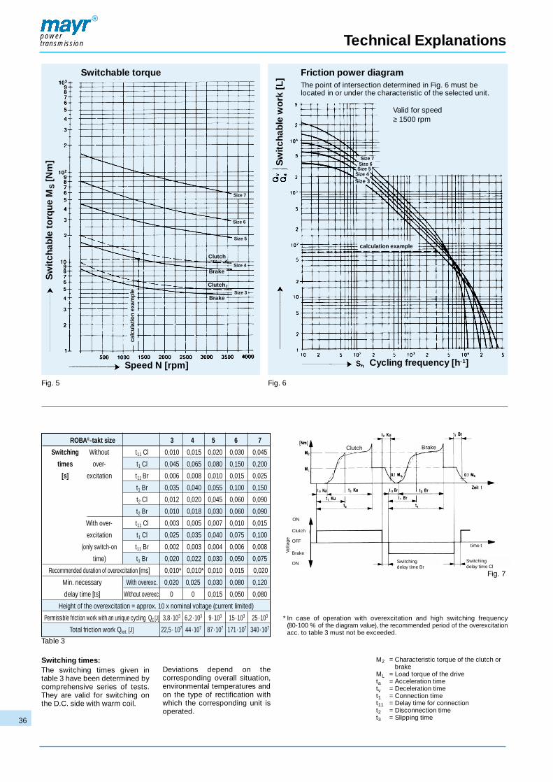
Fig. 5 Fig. 6
Friction power diagramThe point of intersection determined in Fig. 6 must be located in or under the characteristic of the selected unit.
Valid for speed≥ 1500 rpm
Switching times:The switching times given in table 3 have been determined bycomprehensive series of tests.They are valid for switching onthe D.C. side with warm coil.
Deviations depend on the corresponding overall situation,environmental temperatures andon the type of rectification withwhich the corresponding unit isoperated.
M2 = Characteristic torque of the clutch orbrake
ML = Load torque of the driveta = Acceleration timetv = Deceleration timet1 = Connection timet11 = Delay time for connectiont2 = Disconnection timet3 = Slipping time
Table 3
Fig. 7
Switchable torque
Speed N [rpm] Cycling frequency [h-1]
calc
ulat
ion
exam
ple
calculation example
Clutch
Clutch
Brake
Brake
Size 3
Size 4
Size 5
Size 6
Size 7
Size 7
* In case of operation with overexcitation and high switching frequency (80-100 % of the diagram value), the recommended period of the overexcitationacc. to table 3 must not be exceeded.
Sw
itch
able
to
rque
MS
[Nm
] Sw
itch
able
wo
rk [
L]
Switching delay time Br
Clutch
OFF
ON
ON
BrakeVolta
ge
Size 6Size 5
Size 4Size 3
Clutch Brake
Switching delay time Cl
time t

powertransmission
®
37
ROBA®-takt switch gear Type 014.000.2
Dimension (mm)
Application
Start – stop – and positioning by switching and controlling of mayr®
clutch brake combinations and mayr® ROBA®-takt clutch brakeunits.
Function
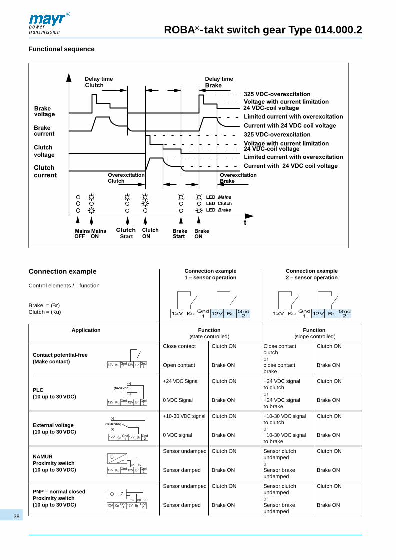
The ROBA®-takt switch gear operates according to the principle ofpulse width modulation with a frequency of 18 kHz. The corresponding coil will be energised by actuating the sensor forclutch and brake. An overtemperature monitor protects the unit fromoverheating. In case of a temperature of >80 °C the coil voltage isswitched-off. The LED “overtemperature unit” lights red.A delay time prevents simultaneous appearance of clutch and braketorques.An overexcitation during switching-on reduces the attraction time of the coil and allows an exact switching and positioning.
Electric connection
PE, L1, N input voltage
+12V / Ku / Gnd1 sensor connection for clutch
+12V / Br / Gnd2 sensor connection for brake
Br1 / Br2 coil connection for brake
Ku1 / Ku2 coil connection for clutch
Technical data
Input voltage 230 VAC ±10 %, 50-60 Hz
Current consumption max. 4 Amp./100 % duty cycle
Idle power consumption < 7 Watt
CoilNOM-voltage 24 VDC
CoilNOM-power max. 96 Watt
CoilNOM-current factory setting to
mayr®-ROBA®-takt-size
Coil-overexcitation max. 325 VDCcurrent limitation is adaptedto the respective coil size
Overexcitation time 2-50 ms (–30 % up to +60 %),externally adjustable(only applicable with coding „overexcitation ON“)
Delay time 2-150 ms (–25 % to +30 %), externally adjustable
Protection IP 20
Ambient temperature 0 °C up to +50 °C
Storage temperature -20 °C up to +70 °C
Conductorcross section 0,14-2,5 mm2 / AWG 26-14
Weight 1,5 kg / 3,31 lb
Mains fuse F1/F2, 4 A (M), IEC 5x20mm
Load fuse F3, the current is adapted to theROBA®-takt sizes. Always use the samespare fuses
Built in temperature switch
Overvoltage category II (two)
Overvoltage protection For the installation in overvoltagecategory III a suitable overvoltageprotection unit is required betweenthe input voltage and the ROBA®-taktswitch gear.
Order example:To be included when ordering, please state: Size Type
Order number X 0 1 4 . 000 . 2ROBA®-takt switch gearSize 3-7
▲
powertransmission
®
38
ROBA®-takt switch gear Type 014.000.2
Functional sequence
Delay time Delay time
Connection example
Control elements / - function
Brake = (Br)Clutch = (Ku)
Application Function Function(state controlled) (slope controlled)
Close contact Clutch ON Close contact Clutch ONclutchor
Open contact Brake ON close contact Brake ONbrake
+24 VDC Signal Clutch ON +24 VDC signal Clutch ONto clutchor
0 VDC Signal Brake ON +24 VDC signal Brake ONto brake
+10-30 VDC signal Clutch ON +10-30 VDC signal Clutch ONto clutchor
0 VDC signal Brake ON +10-30 VDC signal Brake ONto brake
Sensor undamped Clutch ON Sensor clutch Clutch ONundampedor
Sensor damped Brake ON Sensor brake Brake ONundamped
Sensor undamped Clutch ON Sensor clutch Clutch ONundampedor
Sensor damped Brake ON Sensor brake Brake ONundamped
Connection example1 – sensor operation
Connection example2 – sensor operation
Contact potential-free(Make contact)
PLC(10 up to 30 VDC)
External voltage(10 up to 30 VDC)
NAMURProximity switch (10 up to 30 VDC)
PNP – normal closedProximity switch(10 up to 30 VDC)

powertransmission
®
39
ROBA®-takt circuit module Type 004.000._
ApplicationStart and stop of mayr® ROBA®-takt circuit modules and mayr®-clutch brake combinations.Alternating switching of 24 VDC coils, if a 24 VDC power supply isavailable.
Function1 sensor -actuated- clutch is energisedoperation -not actuated- brake is energised
The respective control of the clutch or brake is indicated via LED. The ROBA®-takt circuit module has no over-excitation function.
The brake has priority: The brake is energised independent fromthe sensor position when switching on the 24 VDC power supply. Thecoil is energised with the 24 VDC power supply.
Delay time: To avoid simultaneous interaction of clutch and brakingtorques a delay time of 0 – 100 ms between clutch and brakingtorques can be set, which acts according to the respective pickupand drop-out times of the coils (see switching time table). The settingis made via the potentiometers Ku = clutch (P2) and Br = brake (P1). Factory default setting is 0 ms.
Technical dataInput voltage 24 VDC SELV/PELF ripple ≤5%
(protected with 4 amps. time-lag fuse-link.)
Output voltage 24 VDCOutput power max. 79 WDelay time 0 – 100 ms
(Factory default setting is 0 ms)Ambient temperature 0 °C - +70 °CStorage temperature -20 °C - +85 °CConductor cross section 0,14-1,5 mm2 / AWG 26-14Protection IP 00Design Printed board with attachment assembly
part or in a mounting frame for 35 mmstandard mounting rail.
Max. cycle frequencies: 45 °C 70 °Cup to 1 amp/size 3 + 4 600 600 cycles/minapprox. 2 amp/size 5 + 6 240 180 cycles/minapprox. 3 amp/size 7 120 75 cycles/min
Attention:Higher cycle frequencies will lead to overload and breakdown of theROBA®-takt circuit module.
Electric connection (terminals)1 24 VDC input voltage2 GND voltage supply3+4 brake5+6 clutch7 12 Volt output voltage8 and 9 control inputs
delay time delay time Dimensions with mounting frame (mm)
Order example:To be included when ordering, please state: Size Type
Order number _ 0 0 4 . 000 . _0 = only printed board without frame1 = printed board with mounting frame
▲

Worldwide representation powertransmission
Great BritainMayr Transmissions Ltd.Valley Road, Business ParkKeighley, BD21 4LZWest YorkshireTel.: 0 15 35/66 39 00Fax: 0 15 35/66 32 [email protected]
ItalyMayr Italia S.r.l.Viale Veneto, 335020 Saonara (PD)Tel.: 0 49/8 79 10 20Fax: 0 49/8 79 10 [email protected]
FranceMayr France S.A.Z.A.L. du MinopoleBP 1662160 Bully-Les-MinesTel.: 03.21.72.91.91Fax: [email protected]
USAMayr Corporation4 North StreetWaldwickNJ 07463Tel.: 2 01/4 45-72 10Fax: 2 01/4 45-80 [email protected]
SingaporeMayr Transmission (S)Pte. Ltd. – Blk 133Jurong East Street 13Unit 03-291Singapore 600133 AseanTel.: 0065/65601230Fax: 0065/[email protected]
KoreaMayr Korea60-11, Woongnam-DongROK ChangwonRep. of KoreaTel.: 055/262-4024Fax: 055/[email protected]
TaiwanGerman Tech Auto Co. Ltd.No. 58, Wu Chuan RoadWu-Ku Industrial ParkTaipei Hsien, TaiwanTel.: 02/22990237Fax: 02/[email protected]
Headquarters Chr. MayrGmbH + Co. KGEichenstraße 187665 MauerstettenTel.: 49-83 41/8 04-241Fax: 49-83 41/[email protected]://www.mayr.de
AustriaBenelux StatesBrazilCanadaCzech RepublicDenmarkFinlandGreece
your reliable partner
AustraliaTransmission Australia Pty. Ltd.22 Corporate Ave,3178 Rowville, VictoriaAustralienTel.: 039/755 4444Fax: 039/755 [email protected]
New ZealandSaeco A.D.I.Ltd.36 Hastie AvenueMangere EastP. O. Box 22-256Otahuhu-AucklandTel.: 09/634 7540Fax: 09/634 [email protected]
IndiaNational EngineeringCompany (NENCO)J-225, M.I.D.C. BhosariPune 411026Tel.: 0202/7474529Fax: 0202/[email protected]
JapanShinwa Trading Co. Ltd.1-3, 3-ChomeGoko-Dori, Chuo-kuKobe CityTel.: 078/2512311Fax: 078/[email protected]
HongkongHungaryIndonesiaIsraelMalaysiaNorwayPhilippinesPoland
RomaniaRussiaSlovakiaSloveniaSpainSwedenThailandTurkey
Note:If a country is notshown, please referto headquarters orour web site to beadvised of the nearest responsibleagent.
SwitzerlandMayr Kupplungen AGTobeläckerstrasse 118212 Neuhausen
am RheinfallTel.: 0 52/6 74 08 70Fax: 0 52/6 74 08 [email protected]
ChinaMayr ShanghaiXin Jinqiao Road Nr. 201Room 5227, Pudong Xinqu201206 Shanghai, ChinaTel.: 021/64616990Fax: 021/64617006Mobile: [email protected]
South AfricaTorque TransferPrivate Bag 9Elandsfontein 1406Tel.: 011/3458000Fax: 011/[email protected]
17/0
6/20
05 IM