robacta tc 2000 - fronius hitsauskoneet i … · 1 en dear reader, introduction thank you for the...
TRANSCRIPT
ROBACTA TC 2000/ Operating Instructions/ Spare Parts List
v.01/2013 ENG

0
EN
Dear reader,
Introduction Thank you for the trust you have placed in our company and congratulations on buying this high-quality Fronius product. These instructions will help you familiarise yourself with the product. Reading the instructions carefully will enable you to learn about the many different features it has to offer. This will allow you to make full use of its advantages.
Please also note the safety rules to ensure greater safety when using the product. Careful handling of the product will repay you with years of safe and reliable operation. These are essential prerequisites for excellent results.
Explanation of safety symbols
If you see any of the symbols depicted in the "Safety rules", special care is required.
DANGER! indicates immediate and real danger. If it is not avoided, death or se-rious injury will result.
WARNING! indicates a potentially dangerous situation. Death or serious injury may result if appropriate precautions are not taken.
CAUTION! indicates a situation where damage or injury could occur. If it is not avoided, minor injury and/or damage to property may result.
NOTE! indicates a risk of flawed results and possible damage to the equipment.
IMPORTANT! indicates tips for correct operation and other particularly useful information. It does not indicate a potentially damaging or dangerous situation.
1

2
EN
Contents
Safety rules ................................................................................................................................................ 5General ................................................................................................................................................. 5Proper use ............................................................................................................................................ 5Environmental conditions...................................................................................................................... 6Obligations of the operator.................................................................................................................... 6Obligations of personnel ....................................................................................................................... 6Specific hazards.................................................................................................................................... 6Protecting yourself and others .............................................................................................................. 7Risks from mains current and operating current ................................................................................... 8EMC Device Classifications .................................................................................................................. 8EMC measures ..................................................................................................................................... 9Safety measures at the installation location and during transport ........................................................ 9Safety measures in normal operation ................................................................................................... 10Maintenance and repair ........................................................................................................................ 10Safety inspection................................................................................................................................... 11Disposal ................................................................................................................................................ 11Safety symbols...................................................................................................................................... 11Data protection...................................................................................................................................... 11Copyright............................................................................................................................................... 11
General 13
General ...................................................................................................................................................... 15Device concept ..................................................................................................................................... 15Application areas .................................................................................................................................. 15Warning notices on the device.............................................................................................................. 15Parting agent types and their use ......................................................................................................... 17
Functional principle .................................................................................................................................... 18Functional principle ............................................................................................................................... 18View of magnetic field strength inside the cleaning coil........................................................................ 19
Scope of supply and options...................................................................................................................... 20General ................................................................................................................................................. 20Scope of supply .................................................................................................................................... 20Available options................................................................................................................................... 20
Transport.................................................................................................................................................... 21Vehicles ................................................................................................................................................ 21Transport notices on the packaging...................................................................................................... 21
Controls, connections and mechanical components 23
Safety......................................................................................................................................................... 25Safety.................................................................................................................................................... 25
Standard I/O (X1) connecting plug pin assignment for robot control ......................................................... 26General ................................................................................................................................................. 26Standard I/O (X1) connecting plug pin assignment .............................................................................. 26
Controls, connections and mechanical components.................................................................................. 28General ................................................................................................................................................. 28Control panel......................................................................................................................................... 28Robacta TC 2000 connections and mechanical components............................................................... 29
Installation and commissioning 31
Safety......................................................................................................................................................... 33Safety.................................................................................................................................................... 33
Before commissioning................................................................................................................................ 34Operators, maintenance personnel....................................................................................................... 34Setup regulations .................................................................................................................................. 34Compressed air supply specifications................................................................................................... 34Mains connection .................................................................................................................................. 34
Bolting the cleaning device to the underlying surface (foundation)............................................................ 35
3
Bolting the Robacta TC 2000 together with installation stand to the underlying surface (foundation).. 35Installing the wire cutter ............................................................................................................................. 36
Installing the wire cutter on the Robacta TC 2000 ................................................................................ 36Maximum wire diameter........................................................................................................................ 36How the mechanically-controlled wire cutter works .............................................................................. 36How the electrically-controlled wire cutter works .................................................................................. 36
Filling the dipping bowl with parting agent ................................................................................................. 37Filling the dipping bowl with parting agent ............................................................................................ 37
Connecting the cleaning device to the "Robacta Reamer" parting agent container................................... 38Connecting the cleaning device to the "Robacta Reamer" parting agent container ............................. 38
Starting up the cleaning device.................................................................................................................. 39General ................................................................................................................................................. 39Prerequisites for start-up....................................................................................................................... 39
Cleaning programme ................................................................................................................................. 40Overview of program sequence with parting agent nebuliser ............................................................... 40Overview of program sequence with parting agent nebuliser and dipping bowl ................................... 40Cooling welding torch in the dipping bowl............................................................................................. 40Cleaning gas nozzle tip and nozzle fitting............................................................................................. 40Spraying in parting agent ...................................................................................................................... 41Cleaning program sequence with parting agent nebuliser.................................................................... 42Cleaning program sequence with dipping bowl .................................................................................... 43
Troubleshooting, maintenance and disposal 45
Safety......................................................................................................................................................... 47Safety.................................................................................................................................................... 47
Troubleshooting ......................................................................................................................................... 48Troubleshooting .................................................................................................................................... 48
Care, maintenance and disposal ............................................................................................................... 50Before each start-up ............................................................................................................................. 50Daily ...................................................................................................................................................... 50Weekly .................................................................................................................................................. 50Every 3 months ..................................................................................................................................... 50Every 6 months ..................................................................................................................................... 50Every 12 months ................................................................................................................................... 50Disposal ................................................................................................................................................ 50
Technical data 51
Technical data............................................................................................................................................ 53General ................................................................................................................................................. 53Robacta TC 2000 ................................................................................................................................. 53
Appendix 55
Spare parts list: Robacta TC 2000............................................................................................................. 56Circuit diagram: Robacta TC 2000............................................................................................................. 59
4
EN
Safety rules
General
Proper use
The device is manufactured using state-of-the-art technology and according to recognised safety standards. If used incorrectly or misused, however, it can cause:- injury or death to the operator or a third party,- damage to the device and other material assets belonging to the operat-
ing company,- inefficient operation of the device.
All persons involved in commissioning, operating, maintaining and servicing the device must:- be suitably qualified,- have sufficient knowledge of automated welding, and- read and carefully follow these operating instructions as well as the oper-
ating instructions for all system components.
The operating instructions must always be at hand wherever the device is be-ing used. In addition to the operating instructions, attention must also be paid to any generally applicable and local regulations regarding accident preven-tion and environmental protection.
All safety and danger notices on the device - must be in a legible state, - must not be damaged, - must not be removed,- must not be covered, pasted or painted over.
For the location of the safety and danger notices on the device, refer to the section headed "General" in the operating instructions for the device.Before commissioning the device, rectify any faults that could compromise safety.This is for your personal safety!
The device is to be used exclusively for its intended purpose.
The device is intended solely for the electromagnetic cleaning of Fronius weld-ing torches.Any use above and beyond this purpose is deemed improper. The manufac-turer shall not be held liable for any damage arising from such usage.
Proper use includes:- carefully reading and following all the instructions given in the operating
instructions - studying and obeying all safety and danger notices carefully- performing all stipulated inspection and servicing work.
The device is designed for use in industry and the workshop. The manufactur-er accepts no responsibility for any damage caused through use in a domestic setting.
The manufacturer likewise accepts no liability for inadequate or incorrect re-sults.
5
Environmental conditions
Obligations of the operator
Obligations of personnel
Specific hazards
Operation or storage of the device outside the stipulated area will be deemed as not in accordance with the intended purpose. The manufacturer shall not be held liable for any damage arising from such usage.
Ambient temperature range:- during operation: 0 °C to + 40 °C (32 °F to 104 °F)- during transport and storage: -25 °C to +55 °C (-13 °F to 131 °F)
Relative humidity:- up to 50 % at 40 °C (104 °F)- up to 90 % at 20 °C (68 °F)
Keep ambient air free from dust, acids, corrosive gases and substances, etc.
Can be used at altitudes of up to 2000 m (6500 ft)
The operator must only allow persons to work with the device who: - are familiar with the fundamental instructions regarding safety at work and
accident prevention and have been instructed in how to use the device- have read and understood these operating instructions, especially the
section "safety rules", and have confirmed as much with their signatures - are trained to produce the required results.
Checks must be carried out at regular intervals to ensure that operators are working in a safety-conscious manner.
Before using the device, all persons instructed to do so undertake:- to observe the basic instructions regarding safety at work and accident
prevention- to read these operating instructions, especially the "Safety rules" section
and sign to confirm that they have understood them and will follow them.
Before leaving the workplace, ensure that people or property cannot come to any harm in your absence.
Stay out of the working area of the robot.
The device must be incorporated into a higher-level safety system within a se-cured area.
If this area has to be accessed when setup and maintenance work is carried out, make sure that- the entire system is switched off for the duration of the work in this area- and that it is prevented from starting up accidentally, e.g. as the result of
a control fault
In addition to these operating instructions, the safety rules issued by the robot manufacturer must also be observed.
6
EN
Protecting your-self and othersElectromagnetic fields may pose as yet unknown risks to health:- Effects on the health of persons in the vicinity, e.g. those with pacemak-
ers, metallic implants and hearing aids- Forbidden for anyone wearing a pacemaker: people fitted with a pace-
maker must consult their doctor before working with the device or entering its immediate vicinity
- Forbidden for anyone with metal implants: people fitted with metal im-plants must consult their doctor before working with the device or entering its immediate vicinity
Magnetic fields generated by the high amperage can cause ferromagnetic parts such as spatter accumulations to be ejected from the cleaning opening. To prevent injury, never look into in the cleaning opening while the device is switched on; protective goggles with side protection must be worn at all times.
Persons involved with welding expose themselves to numerous risks, e.g.:- flying sparks and hot pieces of metal- arc radiation, which can damage eyes and skin
- risk of electrocution from mains current and welding current
- greater noise pollution
- harmful welding fumes and gases
Anyone working on the workpiece while welding is in progress must wear suit-able protective clothing with the following properties:- flame-resistant- insulating and dry- covers the whole body, is undamaged and in good condition- safety helmet- trousers with no turn-ups
Protective clothing refers to a variety of different items. Operators should:- protect eyes and face from UV rays, heat and sparks using a protective
visor and regulation filter.- wear regulation protective goggles with side protection behind the protec-
tive visor.- wear stout footwear that provides insulation even in wet conditions.- protect the hands with suitable gloves (electrically insulated and providing
protection against heat).- wear ear protection to reduce the harmful effects of noise and to prevent
injury.
Keep all persons, especially children, out of the working area while any devic-es are in operation or welding is in progress. If, however, there are people in the vicinity,- make them aware of all the dangers (dazzling by arc, injury from flying
sparks, inhalation of harmful welding fumes, noise, possible danger from mains or welding current, possible danger from electromagnetic fields, possible danger from the magnetic field around the cleaning opening, me-chanically-powered parts, compressed air/parting agent mixture ejected from the cleaning opening, flying shavings and similar matter, etc.),
- provide suitable protective equipment or- erect suitable safety screens/curtains.
7
Risks from mains current and oper-ating current
EMC Device Clas-sifications
An electric shock is life threatening and can be fatal.
Do not touch live parts either inside or outside the device.
All cables and leads must be secured, undamaged, insulated and adequately dimensioned. Loose connections, scorched, damaged or inadequately dimen-sioned cables and leads must be repaired/replaced immediately.
Only switch on the device when all output connections have been established correctly.
Only operate the device on a mains supply with a ground conductor. If the de-vice is operated on a mains supply without a ground conductor, this will be deemed as gross negligence. The manufacturer shall not be held liable for any damage arising from such usage.
Arrange for the mains cable to be checked regularly by a qualified electrician to ensure the ground conductor is functioning properly.
Switch off unused devices.
Disconnect the mains plug before working on the device.
Attach a clearly legible and easy-to-understand warning sign to the device to prevent anyone from plugging the mains plug back in and switching it on again.
After opening the device:- discharge all live components- ensure that all components in the device are de-energised.
If work on live parts is required, appoint a second person to switch off the main switch at the right moment.
The housing screws provide an adequate PE conductor connection for earth-ing the housing. The screws must never be replaced with different screws un-less a reliable PE conductor connection is set up.
Devices in emission class A:- Are only designed for use in industrial settings- Can cause line-bound and radiated interference in other areas
Devices in emission class B:- Satisfy the emissions criteria for residential and industrial areas.
This is also true for residential areas in which the energy is sup-plied from the public low-voltage mains.
EMC device classification as per the rating plate or technical data.
8
EN
EMC measuresSafety measures at the installation location and dur-ing transport
Warning, electromagnetic field. Electromagnetic fields may pose as yet un-known risks to health.
It is the operator's responsibility to ensure that no electromagnetic interference occurs in electrical and electronic devices.If electromagnetic interference is detected, the operator is obliged to take ac-tion to rectify the situation.
Check for possible problems, and check and evaluate neighbouring devices' resistance to interference according to national and international require-ments:- Safety devices- Power, signal and data transfer lines- IT and telecommunications devices- Measuring and calibrating devices- Health of neighbouring persons
Supporting measures for avoidance of EMC problems:1. Mains supply
- If electromagnetic interference arises despite the correct mains con-nection, additional measures are necessary (e.g. use of a suitable line filter)
2. Shielding, if necessary- Shield off other nearby devices- Shield off entire welding installation
3. Do not have any magnetic or electronic data carriers about your person: magnetic or electronic data carriers can be damaged by the magnetic fields generated when the device is in use.
4. Do not have any watches or pieces of metal about your person. Watches can be damaged when the device is in use.
A device toppling over could easily kill someone. Place the device on a solid, level surface such that it remains stable- The maximum permissible tilt angle is 10°.
Special regulations apply in rooms at risk of fire or explosion- Observe relevant national and international regulations.
9
Safety measures in normal opera-tion
Maintenance and repair
Use internal directives and checks to ensure that the workplace environment is always clean and clearly laid out.
Only set up and operate the device in accordance with the degree of protec-tion shown on the rating plate.
When setting up the device, ensure an all-round clearance of at least 0.5 m (19.69 in.) from any surrounding objects, e.g. walls, other devices or objects.
The device must be set up at least 1 m (40 in.) away from computers, control lines and the welding process.
Position the device to prevent welding spatter coming into contact with the cleaning device.
Before transporting the device, allow parting agent to drain completely.
When transporting the device, observe the relevant national and local guide-lines and accident prevention regulations. This applies especially to guidelines regarding the risks arising during transport.
After transporting the device, the device must be visually inspected for dam-age before commissioning. Any damage must be repaired by trained service technicians before commissioning the device.
Only operate the device when all safety devices are fully functional. If the safe-ty devices are not fully functional, there is a risk of- injury or death to the operator or a third party,- damage to the device and other material assets belonging to the operator,- inefficient operation of the device.
Any safety devices that are not functioning properly must be repaired before switching on the device.
Never bypass or disable safety devices.
Before switching on the device, ensure that no one is likely to be endangered.
Check the device at least once a week for obvious damage and proper func-tioning of safety devices.
- Only use suitable original parting agent from the manufacturer.- Observe the information on the parting agent safety data sheets when
handling parting agent. The parting agent safety data sheets may be ob-tained from your service centre or downloaded from the manufacturer's website.
- Do not mix the manufacturer's parting agent with other parting agents.- If damage results from using a different parting agent, the manufacturer
accepts no liability. In addition, no warranty claims will be entertained.- Used parting agent must be disposed of properly in accordance with the
relevant national and international regulations.
It is impossible to guarantee that bought-in parts are designed and manufac-tured to meet the demands made of them, or that they satisfy safety require-ments. Use only original replacement and wearing parts (also applies to standard parts).Do not make any modifications, alterations, etc. to the device without the man-ufacturer's consent.Parts that are not in perfect condition must be replaced immediately.When ordering, please give the precise designation and part number as shown in the spare parts list, as well as the serial number of your device.
10
EN
Safety inspectionDisposal
Safety symbols
Data protection
Copyright
The manufacturer recommends that a safety inspection of the device is per-formed at least once every 12 months.
A safety inspection should be carried out by a qualified electrician- after any changes are made- after any additional parts are installed, or after any conversions- after repair, care and maintenance has been carried out- at least every twelve months.
For safety inspections, follow the appropriate national and international stand-ards and directives.
Further details on safety inspection and calibration can be obtained from your service centre. They will provide you on request with any documents you may re-quire.
Do not dispose of this device with normal domestic waste! To comply with the European Directive 2002/96/EC on Waste Electrical and Electronic Equip-ment and its implementation as national law, electrical equipment that has reached the end of its life must be collected separately and returned to an ap-proved recycling facility. Any device that you no longer require must either be returned to your dealer or given to one of the approved collection and recycling facilities in your area. Ignoring this European Directive may have potentially adverse affects on the environment and your health!
Devices with the CE mark satisfy the essential requirements of the low-voltage and electromagnetic compatibility directive (e.g. relevant product norms from the EN 60 974 series).
Devices with the CSA test mark satisfy the requirements of the relevant stand-ards in Canada and the USA.
The user is responsible for the safekeeping of any changes made to the fac-tory settings. The manufacturer accepts no liability for any deleted personal settings.
Copyright of these operating instructions remains with the manufacturer.
The text and illustrations are all technically correct at the time of printing. We reserve the right to make changes. The contents of the operating instructions shall not provide the basis for any claims whatsoever on the part of the pur-chaser. If you have any suggestions for improvement, or can point out any mistakes that you have found in the instructions, we will be most grateful for your comments.
11

12

General

EN
General
Device concept
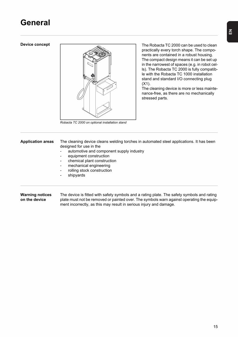
Robacta TC 2000 on optional installation stand
The Robacta TC 2000 can be used to clean practically every torch shape. The compo-nents are contained in a robust housing. The compact design means it can be set up in the narrowest of spaces (e.g. in robot cel-ls). The Robacta TC 2000 is fully compatib-le with the Robacta TC 1000 installation stand and standard I/O connecting plug (X1).The cleaning device is more or less mainte-nance-free, as there are no mechanically stressed parts.
Application areas The cleaning device cleans welding torches in automated steel applications. It has been designed for use in the- automotive and component supply industry- equipment construction- chemical plant construction- mechanical engineering- rolling stock construction- shipyards
Warning notices on the device
The device is fitted with safety symbols and a rating plate. The safety symbols and rating plate must not be removed or painted over. The symbols warn against operating the equip-ment incorrectly, as this may result in serious injury and damage.
15
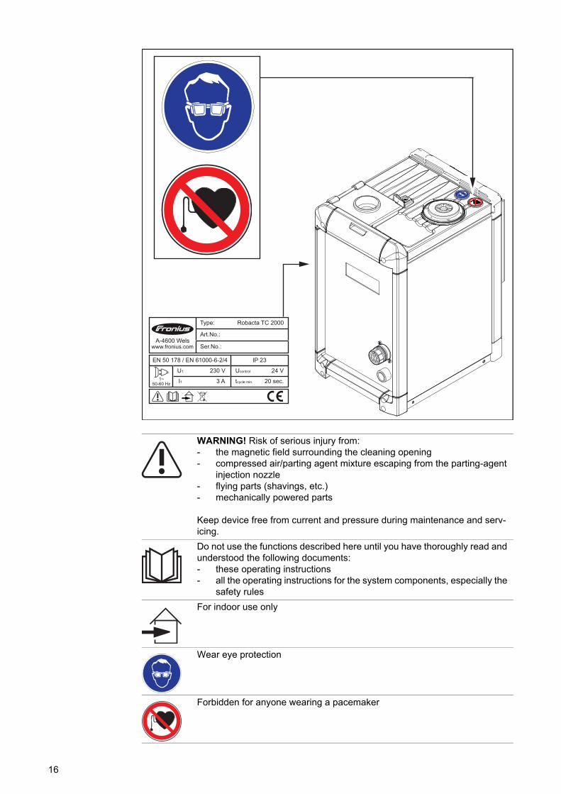
WARNING! Risk of serious injury from:- the magnetic field surrounding the cleaning opening- compressed air/parting agent mixture escaping from the parting-agent
injection nozzle- flying parts (shavings, etc.)- mechanically powered parts
Keep device free from current and pressure during maintenance and serv-icing.
Do not use the functions described here until you have thoroughly read and understood the following documents:- these operating instructions- all the operating instructions for the system components, especially the
safety rules
For indoor use only
Wear eye protection
Forbidden for anyone wearing a pacemaker
1~50-60 Hz
U1
IP 23
230 V
I1 3 A
24 V
20 sec.
Ucontrol
tcycle min.
EN 50 178 / EN 61000-6-2/4
A-4600 Wels www.fronius.com
Type:
Ser.No.:
Art.No.:
Robacta TC 2000
16
EN
Parting agenttypes and their use
Parting agent types and their use:- "Robacta TC Cool / Robacta TC Cool MD" parting agent for immersing the welding
torch in the dipping bowl- "Robacta Reamer" parting agent for spraying the torch after the cleaning operation
Recommendation for using the dipping bowl with- Gas-cooled welding torches- Water-cooled welding torches in the upper power range (hot gas nozzles)
Spraying the welding torch with "Robacta Reamer" parting agent is recommended for all applications.
NOTE! Parting agents are not included in the scope of supply.
17
Functional principle
Functional princi-ple
- Once the cleaning device is connected to the mains power supply, the mains voltage indicator lights up. The capacitors, which store energy for the cleaning operation, are discharged and no outputs are activated.
- The device temperature is checked before the capacitors are charged. If it lies within the tolerance range, the capacitors are charged in preparation for a cleaning opera-tion. If the operating temperature is exceeded, the overtemperature indicator lights up. Capacitor charging only begins once the temperature has fallen to the permitted op-erating temperature.
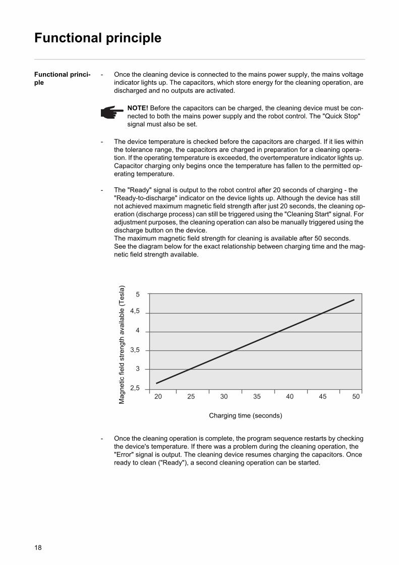
- The "Ready" signal is output to the robot control after 20 seconds of charging - the "Ready-to-discharge" indicator on the device lights up. Although the device has still not achieved maximum magnetic field strength after just 20 seconds, the cleaning op-eration (discharge process) can still be triggered using the "Cleaning Start" signal. For adjustment purposes, the cleaning operation can also be manually triggered using the discharge button on the device. The maximum magnetic field strength for cleaning is available after 50 seconds. See the diagram below for the exact relationship between charging time and the mag-netic field strength available.
- Once the cleaning operation is complete, the program sequence restarts by checking the device's temperature. If there was a problem during the cleaning operation, the "Error" signal is output. The cleaning device resumes charging the capacitors. Once ready to clean ("Ready"), a second cleaning operation can be started.
NOTE! Before the capacitors can be charged, the cleaning device must be con-nected to both the mains power supply and the robot control. The "Quick Stop" signal must also be set.
Ma
gne
tic f
ield
str
engt
h av
aila
ble
(T
esla
)
Charging time (seconds)
5
4,5
4
3,5
3
2,520 25 30 35 40 45 50
18
EN
- Automatic refilling of the dipping bowl with "Robacta TC Cool / Robacta TC Cool MD" parting agent ensures an optimum fill level in the dipping bowl. After draining the "Ro-bacta TC Cool / Robacta TC Cool MD" parting agent container, the fill level in the dip-ping bowl drops. The level sensor detects that the level has dropped too low and the fill level indicator lights up. At the same time, the "Fluid level control" signal is trans-mitted to the robot control.- The device cleaning function remains available even if the fill level indicator is il-
luminated.
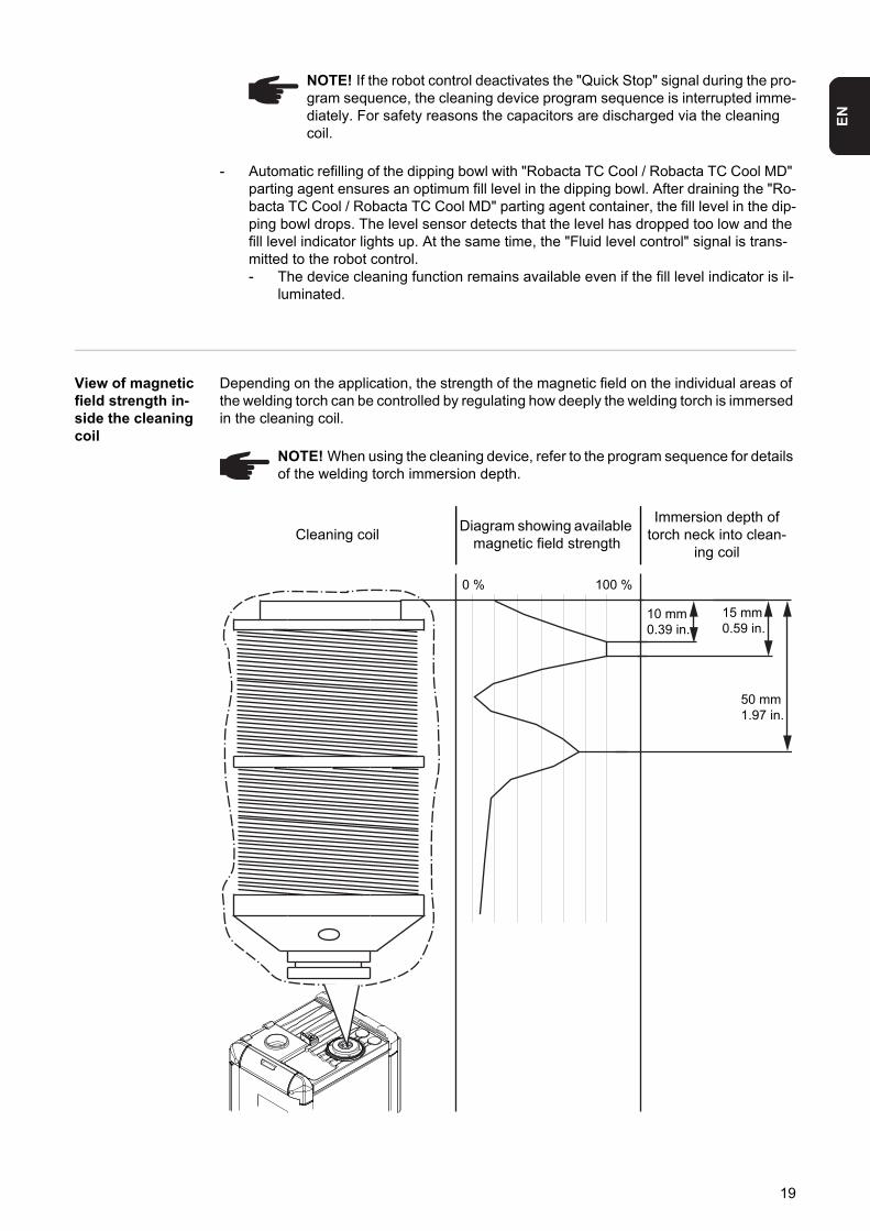
View of magnetic field strength in-side the cleaning coil
Depending on the application, the strength of the magnetic field on the individual areas of the welding torch can be controlled by regulating how deeply the welding torch is immersed in the cleaning coil.
NOTE! If the robot control deactivates the "Quick Stop" signal during the pro-gram sequence, the cleaning device program sequence is interrupted imme-diately. For safety reasons the capacitors are discharged via the cleaning coil.
NOTE! When using the cleaning device, refer to the program sequence for details of the welding torch immersion depth.
Cleaning coilDiagram showing available
magnetic field strength
Immersion depth of torch neck into clean-
ing coil
0 % 100 %
50 mm1.97 in.
10 mm0.39 in.
15 mm0.59 in.
19
Scope of supply and options
General The cleaning device can be operated in conjunction with various options. This makes it possible to optimise various procedures in the welding process, as necessitated by the par-ticular field of application.
Scope of supply - Robacta TC 2000 with dipping bowl and integral cleaning unit- Standard I/O connecting plug (X1) without cable- 4 screws for fitting the Robacta TC 2000 to the installation stand
Available options Available options for the Robacta TC 2000- Installation stand (available in various heights)- Wire cutter- Wire cutter fitting set- Parting agent nebuliser installation set- Robot interface
20
EN
Transport
Vehicles The device is to be transported by the following vehicles:- on pallets using a counterbalanced lift truck- on pallets using a lift truck- manually
Transport notices on the packaging
WARNING! Equipment that falls or topples over can cause serious or even fatal injury.- When transporting the device on a counterbalanced lift truck or lift truck, se-
cure it to prevent it from falling over- Do not suddenly change direction, brake or accelerate
CAUTION! Risk of damage due to incorrect transport. Observe the transport no-tices on the device packaging.
21

22
Controls, connections and mechani-cal components

EN
Safety
Safety Observe the following safety rules for all work described in the "Control elements, connec-tions and mechanical components" section.
WARNING! Operating the equipment incorrectly can cause serious injury and damage. The functions described must only be used by trained and qualified per-sonnel. Do not use the functions described here until you have thoroughly read and understood the following documents:- these operating instructions- all the operating instructions for the system components, especially the safe-
ty rules
25
Standard I/O (X1) connecting plug pin assignment for robot control
General
The standard I/O (X1) connecting plug for connecting the cleaning device to the robot con-trol is part of the scope of supply. The cable harness must be adapted to the connection technology on the robot control.
Standard I/O (X1) connecting plug pin assignment
WARNING! An electric shock can be fatal. The cleaning device must remain de-energised until the installation is fully complete.
NOTE! To avoid malfunctions, keep the cable length between the cleaning device and robot control as short as possible.
WARNING! Danger of serious injury and material damage due to unexpected start-up of the cleaning device / system components. Only assign the "Quick Stop" signal input once:- either "HIGH - Quick Stop" - or "LOW - Quick Stop"
NOTE! Depending on the demands placed on the robot application, not all input and output signals (commands) need to be used. The underlined I/O signals rep-resent the minimum command subset required in each instance.
26
EN
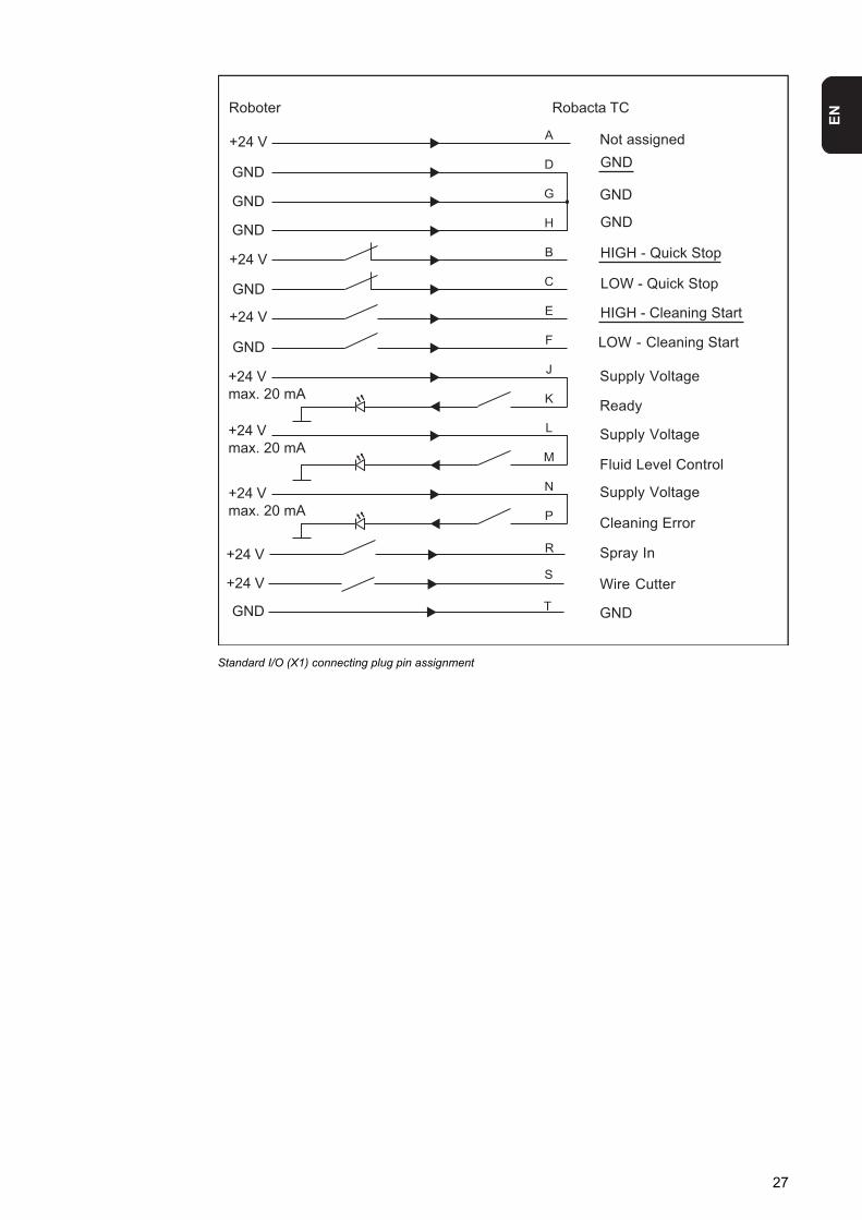
Standard I/O (X1) connecting plug pin assignment
R
S
T
Not assigned
HIGH - Quick Stop
+24 V
Roboter
+24 V
+24 Vmax. 20 mA
+24 Vmax. 20 mA
+24 Vmax. 20 mA
+24 V
+24 V
+24 V
GND
GND
GND
GND
GND
GND
LOW - Quick Stop
GND
HIGH - Cleaning Start
LOW - Cleaning Start
GND
GND
Supply Voltage
Ready
Supply Voltage
Fluid Level Control
Supply Voltage
Cleaning Error
CT atcaboR
Spray In
GND
Wire Cutter
27
Controls, connections and mechanical components
General All functions of the Robacta TC are activated by the robot control. For adjustment, the cleaning operation can be manually triggered on the Robacta TC housing. For easier op-eration, the Robacta TC is fitted with indicator lights.
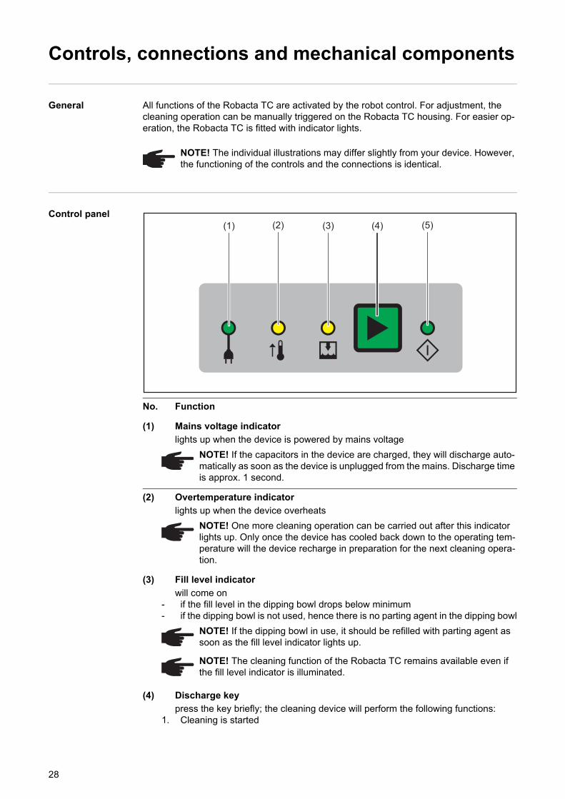
Control panel
No. Function
(1) Mains voltage indicator
lights up when the device is powered by mains voltage
(2) Overtemperature indicator
lights up when the device overheats
(3) Fill level indicator
will come on- if the fill level in the dipping bowl drops below minimum- if the dipping bowl is not used, hence there is no parting agent in the dipping bowl
(4) Discharge key
press the key briefly; the cleaning device will perform the following functions:1. Cleaning is started
NOTE! The individual illustrations may differ slightly from your device. However, the functioning of the controls and the connections is identical.
NOTE! If the capacitors in the device are charged, they will discharge auto-matically as soon as the device is unplugged from the mains. Discharge time is approx. 1 second.
NOTE! One more cleaning operation can be carried out after this indicator lights up. Only once the device has cooled back down to the operating tem-perature will the device recharge in preparation for the next cleaning opera-tion.
NOTE! If the dipping bowl in use, it should be refilled with parting agent as soon as the fill level indicator lights up.
NOTE! The cleaning function of the Robacta TC remains available even if the fill level indicator is illuminated.
(1) (2) (3) (4) (5)
28
EN
press and hold the key; the cleaning device will perform the following functions in se-quence: 1. Cleaning is started2. Wire cutter is activated3. Compressed air/parting agent mixture is sprayed out of the cleaning opening
(5) Ready-to-clean indicator
lights up when the device is ready to clean
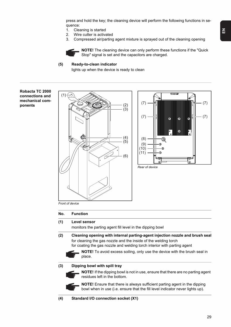
Robacta TC 2000 connections and mechanical com-ponents
Front of device
Rear of device
No. Function
(1) Level sensor
monitors the parting agent fill level in the dipping bowl
(2) Cleaning opening with internal parting-agent injection nozzle and brush seal
for cleaning the gas nozzle and the inside of the welding torchfor coating the gas nozzle and welding torch interior with parting agent
(3) Dipping bowl with spill tray
(4) Standard I/O connection socket (X1)
NOTE! The cleaning device can only perform these functions if the "Quick Stop" signal is set and the capacitors are charged.
(4)(5)
(6)
(2)(3)
(1)
(7)
(7)
(7)
(7)
(8)(9)
(10)(11)
NOTE! To avoid excess soiling, only use the device with the brush seal in place.
NOTE! If the dipping bowl is not in use, ensure that there are no parting agent residues left in the bottom.
NOTE! Ensure that there is always sufficient parting agent in the dipping bowl when in use (i.e. ensure that the fill level indicator never lights up).
29
(5) Mains cable with strain relief device
(6) Spatter tray for welding residues
(7) Recesses for the wire cutter holder
for attaching the wire cutter holder to the cleaning device
(8) Drain hose
for emptying the dipping bowl
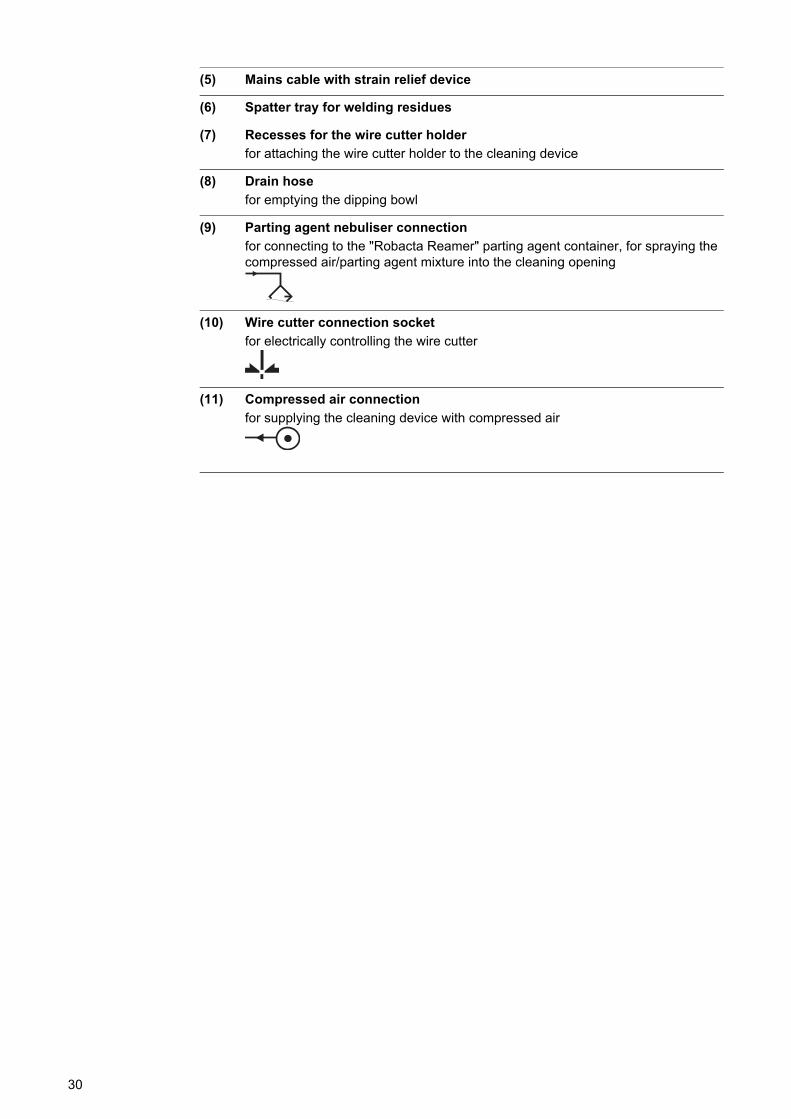
(9) Parting agent nebuliser connection
for connecting to the "Robacta Reamer" parting agent container, for spraying the compressed air/parting agent mixture into the cleaning opening
(10) Wire cutter connection socket
for electrically controlling the wire cutter
(11) Compressed air connection
for supplying the cleaning device with compressed air
30

Installation and commissioning

EN
Safety
Safety Observe the following safety rules for all work described in the "Installation and start-up" section.
WARNING! Incorrect operation or poorly executed work can cause serious injury or damage. All activities described in these operating instructions may only be carried out by trained and qualified personnel. All functions described in these op-erating instructions may only be used by trained and qualified personnel. Do not carry out any of the work or use any of the functions described until you have fully read and understood the following documents:- these operating instructions- all the operating instructions for the system components, especially the safe-
ty rules
WARNING! Machines that start up automatically can cause serious injury and damage. In addition to these operating instructions, the safety rules issued by the manufacturers of the robot and welding systems must also be observed. For your personal safety, ensure that all protective measures have been taken and will re-main in place while you are in the working area of the robot.
WARNING! Risk of serious injury from electric shock and mechanically powered parts. Before performing work on the cleaning device or any connected system components:- disconnect the customer's compressed air and power supplies from the
cleaning device and the connected system components- ensure that they remain disconnected until all work is complete
WARNING! Whenever the cleaning device is supplied with voltage and/or com-pressed air, a risk of serious injury exists from:- the magnetic field surrounding the cleaning opening- flying parts (shavings, etc.)- compressed air/parting agent mixture escaping from the parting-agent injec-
tion nozzle- activated wire cutter
If work has to be performed on the cleaning device while it is supplied with voltage and/or compressed air:- keep all ferromagnetic parts, such as tools, away from the device- keep your body, especially your hands, face and hair, any objects and all
clothing away from the cleaning opening and the wire cutter- wear ear protection- wear protective goggles with side protection
33
Before commissioning
Operators, main-tenance person-nel
Setup regulations The device is tested to IP 23, meaning:- protection against penetration by solid foreign bodies with diameters > 12.5 mm (0.49
in.)- protection against direct sprays of water at any angle up to 60° from the vertical
The device must not be set up and operated outdoors. The built in electrical parts must be protected from direct wetting.
Compressed air supply specifica-tions
To ensure that the torch neck cleaning device functions correctly, the following com-pressed air supply specifications must be met:- Establish compressed air supply using a pressure limiter and compressed air filter- Provide compressed air quality conforming to ISO 8573-1:2001, class 7 4 3, instru-
ment air- Solid particle concentration ≤ 10 mg/m3
- Vapour pressure dew point ≤ + 3°C- Oil concentration ≤ 1 mg/m3
Mains connection The cleaning device is designed to run at the mains voltage indicated on the rating plate. The fuse protection required for the mains cable can be found in the "Technical data" sec-tion. If there is no mains cable or mains plug on your device, fit one that conforms to na-tional standards.
NOTE! The device must only be used by 1 person at a time. It is also necessary to ensure that no-one else is within the working area of the device when the de-vice is being used.
NOTE! The device must only be serviced by 1 person at a time. It is also neces-sary to ensure that no-one else is within the working area of the device when the device is being worked on.
NOTE! The device must be set up at least 1 m (40 in.) away from computers, con-trol lines and the welding process.
NOTE! When setting up the device, ensure an all-round clearance of at least 0.5 m (19.69 in.) from any surrounding objects, e.g. walls, other devices or ob-jects.
NOTE! Position the device to prevent welding spatter coming into contact with the cleaning device.
CAUTION! Risk of serious damage as the result of incorrect mains voltage. If the mains voltage lies outside the tolerances given in the technical data, do not under any circumstances connect the device to the mains.
NOTE! An inadequately dimensioned electrical installation can cause serious damage. The mains cable and its fuse must be dimensioned to suit the device be-ing used. The technical data shown on the rating plate applies.
34
EN
Bolting the cleaning device to the underlying sur-face (foundation)
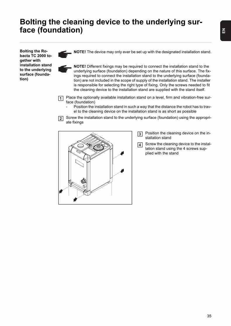
Bolting the Ro-bacta TC 2000 to-gether with installation stand to the underlying surface (founda-tion)
Place the optionally available installation stand on a level, firm and vibration-free sur-face (foundation)- Position the installation stand in such a way that the distance the robot has to trav-
el to the cleaning device on the installation stand is as short as possible
Screw the installation stand to the underlying surface (foundation) using the appropri-ate fixings
Position the cleaning device on the in-stallation stand
Screw the cleaning device to the instal-lation stand using the 4 screws sup-plied with the stand
NOTE! The device may only ever be set up with the designated installation stand.
NOTE! Different fixings may be required to connect the installation stand to the underlying surface (foundation) depending on the nature of this surface. The fix-ings required to connect the installation stand to the underlying surface (founda-tion) are not included in the scope of supply of the installation stand. The installer is responsible for selecting the right type of fixing. Only the screws needed to fit the cleaning device to the installation stand are supplied with the stand itself.
1
2
3
4
35
Installing the wire cutter
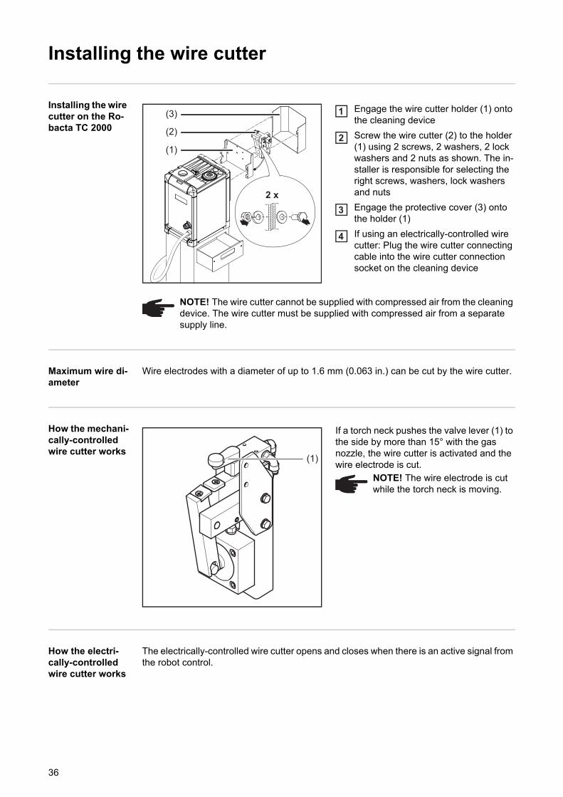
Installing the wire cutter on the Ro-bacta TC 2000
Engage the wire cutter holder (1) onto the cleaning device
Screw the wire cutter (2) to the holder (1) using 2 screws, 2 washers, 2 lock washers and 2 nuts as shown. The in-staller is responsible for selecting the right screws, washers, lock washers and nuts
Engage the protective cover (3) onto the holder (1)
If using an electrically-controlled wire cutter: Plug the wire cutter connecting cable into the wire cutter connection socket on the cleaning device
Maximum wire di-ameter
Wire electrodes with a diameter of up to 1.6 mm (0.063 in.) can be cut by the wire cutter.
How the mechani-cally-controlled wire cutter works
If a torch neck pushes the valve lever (1) to the side by more than 15° with the gas nozzle, the wire cutter is activated and the wire electrode is cut.
How the electri-cally-controlled wire cutter works
The electrically-controlled wire cutter opens and closes when there is an active signal from the robot control.
(1)
(2)
(3)
2 x
1
2
3
4
NOTE! The wire cutter cannot be supplied with compressed air from the cleaning device. The wire cutter must be supplied with compressed air from a separate supply line.
(1)
NOTE! The wire electrode is cut while the torch neck is moving.
36
EN
Filling the dipping bowl with parting agent
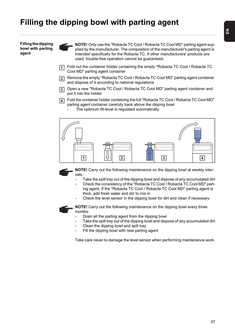
Filling the dipping bowl with parting agent
Fold out the container holder containing the empty "Robacta TC Cool / Robacta TC Cool MD" parting agent container
Remove the empty "Robacta TC Cool / Robacta TC Cool MD" parting agent container and dispose of it according to national regulations
Open a new "Robacta TC Cool / Robacta TC Cool MD" parting agent container and put it into the holder
Fold the container holder containing the full "Robacta TC Cool / Robacta TC Cool MD" parting agent container carefully back above the dipping bowl- The optimum fill-level is regulated automatically
NOTE! Only use the "Robacta TC Cool / Robacta TC Cool MD" parting agent sup-plied by the manufacturer. The composition of the manufacturer's parting agent is intended specifically for the Robacta TC. If other manufacturers' products are used, trouble-free operation cannot be guaranteed.
1
2
3
4
NOTE! Carry out the following maintenance on the dipping bowl at weekly inter-vals:- Take the spill tray out of the dipping bowl and dispose of any accumulated dirt- Check the consistency of the "Robacta TC Cool / Robacta TC Cool MD" part-
ing agent. If the "Robacta TC Cool / Robacta TC Cool MD" parting agent is thick, add fresh water and stir to mix in
- Check the level sensor in the dipping bowl for dirt and clean if necessary
NOTE! Carry out the following maintenance on the dipping bowl every three months:- Drain all the parting agent from the dipping bowl- Take the spill tray out of the dipping bowl and dispose of any accumulated dirt- Clean the dipping bowl and spill tray- Fill the dipping bowl with new parting agent
Take care never to damage the level sensor when performing maintenance work.
3 421
37
Connecting the cleaning device to the "Robacta Reamer" parting agent container
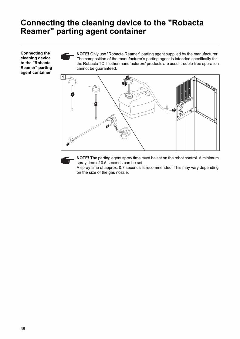
Connecting the cleaning device to the "Robacta Reamer" parting agent container
NOTE! Only use "Robacta Reamer" parting agent supplied by the manufacturer. The composition of the manufacturer's parting agent is intended specifically for the Robacta TC. If other manufacturers' products are used, trouble-free operation cannot be guaranteed.
NOTE! The parting agent spray time must be set on the robot control. A minimum spray time of 0.5 seconds can be set.A spray time of approx. 0.7 seconds is recommended. This may vary depending on the size of the gas nozzle.
5
6
2
3
1
4
7
1
38
EN
Starting up the cleaning device
General
To achieve the best cleaning results, please note the following:- Apply an even layer of parting agent to the inside of the torch- Follow the cleaning sequences as described below- Keep to the specified cleaning positions- Blow out the welding torch with compressed air during the cleaning operation (howev-
er not when parting agent is being actively sprayed into the torch interior)
Prerequisites for start-up
The following requirements must be met before the cleaning device is started up:- Cleaning device is bolted to underlying surface - If present, connect the "Robacta Reamer" parting agent container to the cleaning de-
vice- If using the dipping bowl, the dipping bowl is filled with the "Robacta TC Cool / Robacta
TC Cool MD" parting agent - If present, wire cutter installed and supplied with compressed air- Cleaning device connected to mains- If the cleaning device has been connected to the "Robacta Reamer" parting agent
container: compressed air supply to cleaning device has been established - Cleaning device connected to robot control
NOTE! Not coating the interior of the welding torch may result in permanent soil-ing of the torch when welding begins. Always wet the inside of the welding torch with the manufacturer's "Robacta Reamer" parting agent before starting automat-ic operation.
NOTE! Single, small bits of welding spatter cannot be removed by the cleaning device. However, these small pieces do not influence the welding process.
39
Cleaning programme
Overview of pro-gram sequence with parting agent nebuliser
1. Welding2. Cleaning gas nozzle tip and nozzle fitting3. Spraying in parting agent4. Welding
Overview of pro-gram sequence with parting agent nebuliser and dip-ping bowl
1. Welding2. Cooling torch in dipping bowl3. Cleaning gas nozzle tip and nozzle fitting4. Spraying in parting agent5. Welding
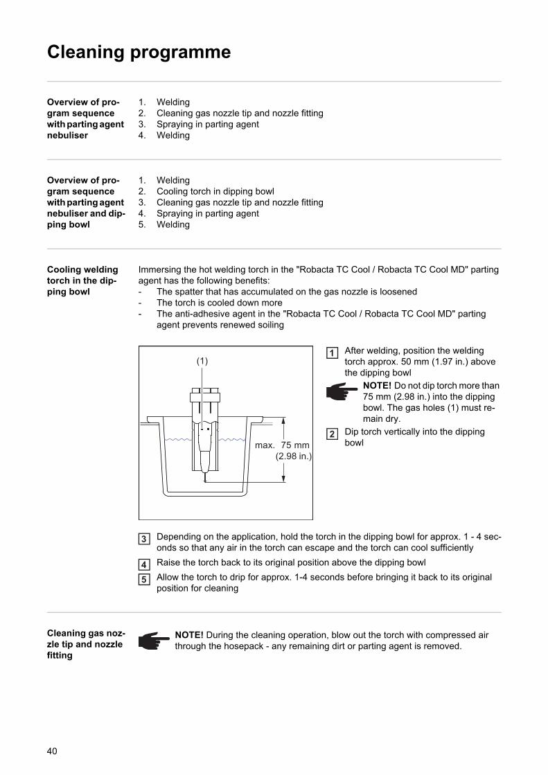
Cooling welding torch in the dip-ping bowl
Immersing the hot welding torch in the "Robacta TC Cool / Robacta TC Cool MD" parting agent has the following benefits:- The spatter that has accumulated on the gas nozzle is loosened- The torch is cooled down more- The anti-adhesive agent in the "Robacta TC Cool / Robacta TC Cool MD" parting
agent prevents renewed soiling
After welding, position the welding torch approx. 50 mm (1.97 in.) above the dipping bowl
Dip torch vertically into the dipping bowl
Depending on the application, hold the torch in the dipping bowl for approx. 1 - 4 sec-onds so that any air in the torch can escape and the torch can cool sufficiently
Raise the torch back to its original position above the dipping bowl
Allow the torch to drip for approx. 1-4 seconds before bringing it back to its original position for cleaning
Cleaning gas noz-zle tip and nozzle fitting
max. 75 mm(2.98 in.)
(1)
NOTE! Do not dip torch more than 75 mm (2.98 in.) into the dipping bowl. The gas holes (1) must re-main dry.
1
2
3
45
NOTE! During the cleaning operation, blow out the torch with compressed air through the hosepack - any remaining dirt or parting agent is removed.
40
EN
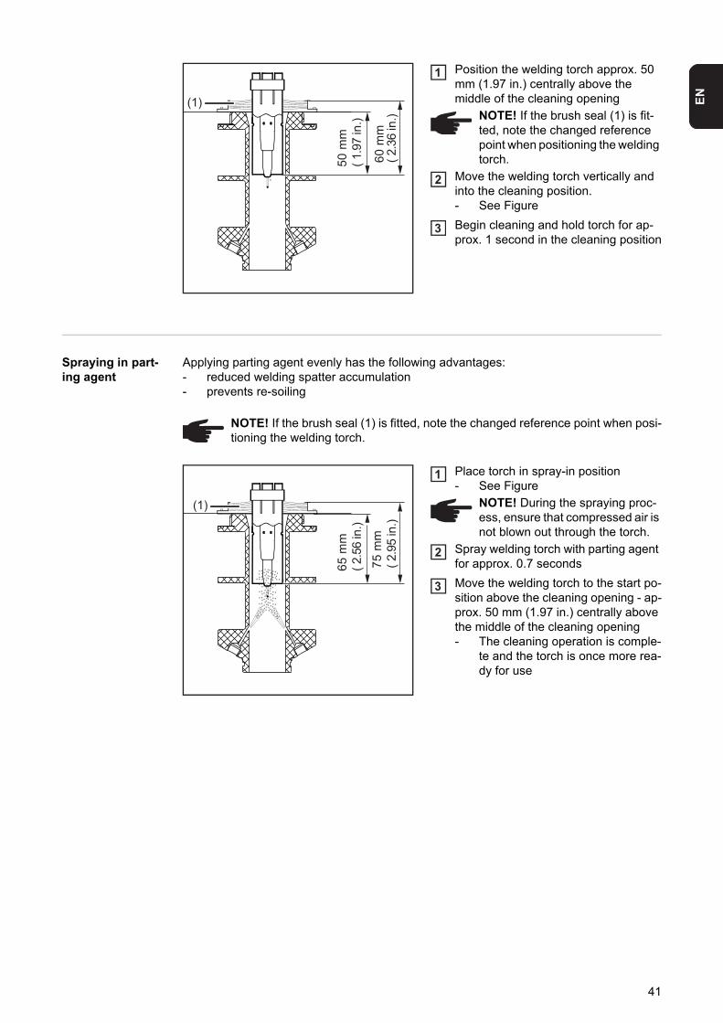
Position the welding torch approx. 50 mm (1.97 in.) centrally above the middle of the cleaning opening
Move the welding torch vertically and into the cleaning position. - See Figure
Begin cleaning and hold torch for ap-prox. 1 second in the cleaning position
Spraying in part-ing agent
Applying parting agent evenly has the following advantages:- reduced welding spatter accumulation- prevents re-soiling
Place torch in spray-in position- See Figure
Spray welding torch with parting agent for approx. 0.7 seconds
Move the welding torch to the start po-sition above the cleaning opening - ap-prox. 50 mm (1.97 in.) centrally above the middle of the cleaning opening- The cleaning operation is comple-
te and the torch is once more rea-dy for use
60 m
m( 2
.36
in.)
50 m
m( 1
.97
in.)
(1)NOTE! If the brush seal (1) is fit-ted, note the changed reference point when positioning the welding torch.
1
2
3
NOTE! If the brush seal (1) is fitted, note the changed reference point when posi-tioning the welding torch.
75 m
m( 2
.95
in.)
65 m
m( 2
.56
in.)
(1) NOTE! During the spraying proc-ess, ensure that compressed air is not blown out through the torch.
1
2
3
41
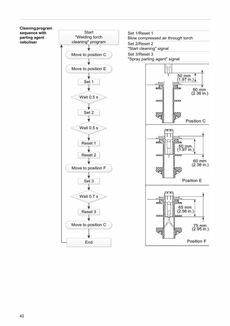
Cleaning program sequence with parting agent nebuliser
42
EN
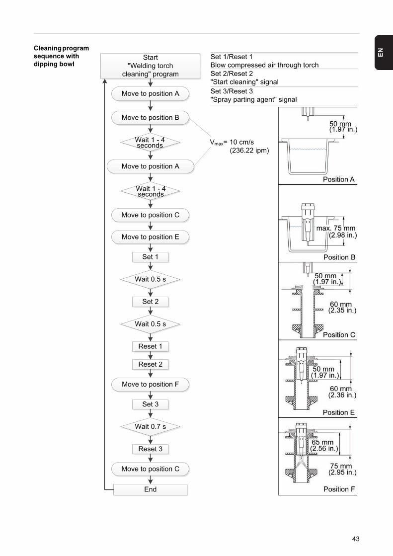
Cleaning programsequence with dipping bowl
43

44
Troubleshooting, maintenance and disposal


EN
Safety
Safety Observe the following safety rules for all work described in the "Troubleshooting, mainte-nance and disposal" section.
WARNING! Incorrect operation or poorly executed work can cause serious injury or damage. All activities described in these operating instructions may only be carried out by trained and qualified personnel. All functions described in these op-erating instructions may only be used by trained and qualified personnel. Do not carry out any of the work or use any of the functions described until you have fully read and understood the following documents:- these operating instructions- all the operating instructions for the system components, especially the safe-
ty rules
WARNING! Machines that start up automatically can cause serious injury and damage. In addition to these operating instructions, the safety rules issued by the manufacturers of the robot and welding systems must also be observed. For your personal safety, ensure that all protective measures have been taken and will re-main in place while you are in the working area of the robot.
WARNING! Risk of serious injury from electric shock and mechanically powered parts. Before performing work on the cleaning device or any connected system components:- disconnect the customer's compressed air and power supplies from the
cleaning device and the connected system components- ensure that they remain disconnected until all work is complete- using a suitable measuring instrument, ensure that electrically charged parts
(e.g. capacitors) have been discharged
WARNING! Whenever the cleaning device is supplied with voltage and/or com-pressed air, a risk of serious injury exists from:- the magnetic field surrounding the cleaning opening- flying parts (shavings, etc.)- compressed air/parting agent mixture escaping from the parting-agent injec-
tion nozzle- activated wire cutter
If work has to be performed on the cleaning device while it is supplied with voltage and/or compressed air:- keep all ferromagnetic parts, such as tools, away from the device- keep your body, especially your hands, face and hair, any objects and all
clothing away from the cleaning opening and the wire cutter- wear ear protection- wear protective goggles with side protection
CAUTION! An inadequate ground conductor connection can cause serious injury or damage. The housing screws provide a suitable ground conductor connection for earthing (grounding) the housing and must NOT be replaced by any other screws which do not provide a reliable ground conductor connection.
47
Troubleshooting
Troubleshooting Mains voltage indicator not lit
Mains cable connected
Cause: Faulty mains cable
Remedy: Check mains cable
Cause: The cleaning device is overheating
Remedy: Allow cleaning device to cool down. Once the permitted operating tempera-ture has been reached, charging starts again. The cleaning device is then ready to clean again
"Ready-to-clean" signal not transmitted to robot control
Mains voltage indicator lit
Cause: Quick Stop is active (HI - Quick Stop = LO / LO - Quick Stop =HI)
Remedy: Deactivate Quick Stop (HI - Quick Stop = HI / LO - Quick Stop =LO)
Cause: Supply to I/O standard connection socket (X1) is faulty
Remedy: Depending on the connection socket, check the assignment of inputs "B" and "H" / "D" and "G"
"Ready-to-clean" signal not transmitted to robot control
Mains voltage indicator lit, overtemperature indicator lit
Cause: The cleaning device is overheating
Remedy: Allow cleaning device to cool down. Once the permitted operating tempera-ture has been reached, charging of the capacitors starts again. The cleaning device is then ready to clean again
Fill level indicator lit
The liquid in the dipping bowl is below the optimum fill level
Cause: "Robacta TC Cool / Robacta TC Cool MD" parting agent container is empty
Remedy: Replace "Robacta TC Cool / Robacta TC Cool MD" parting agent container
Fill level indicator lit
The "Robacta TC Cool / Robacta TC Cool MD" parting agent container is not yet empty
Cause: Level sensor is dirty
Remedy: Clean level sensor with fresh water
Cause: Level sensor faulty
Remedy: Contact After-Sales Service
Fill level indicator lit
A dipping bowl is not available or is not being used
Cause: A parting agent nebuliser is being used
Remedy: Not necessary
48
EN
Fill level indicator not lit
The liquid in the dipping bowl is already below the optimum fill level
Cause: Fill-level sensor faulty
Remedy: Contact After-Sales Service
Parting agent does not spray
The "Robacta Reamer" parting agent container is full
Cause: Not enough spray
Remedy: Adjust spray amount (spray time)
Cause: Dirty suction filter in "Robacta Reamer" parting agent container
Remedy: Blow through suction filter in "Robacta Reamer" parting agent container using compressed air from the inside outwards through the suction hose (see "Con-necting the cleaning device to the "Robacta Reamer" parting agent contain-er")
Cause: Compressed air supply interrupted
Remedy: Establish the compressed air supply
Cause: Compressed air supply line faulty or dirty
Remedy: Clean compressed air supply line, replace if necessary
Cause: Faulty vacuum pump
Remedy: Contact After-Sales Service (arrange for vacuum pump to be replaced)
Cause: Faulty solenoid valve
Remedy: Contact After-Sales Service (arrange for solenoid valve to be replaced)
Parting agent does not spray
Cause: The "Robacta Reamer" parting agent container is empty
Remedy: Fill with parting agent
Pores in the weld seam
Cause: Too much parting agent inside the torch
Remedy: Remove parting agent residue by blowing out the torch interior. Ensure com-pressed air supply
Cause: Too much parting agent inside the torch
Remedy: Reduce amount of parting agent spray (spraying time)
Error is sent to the robot. Overtemperature and fill level indicators flash at the same time, no cleaning takes place
Cause: Quick Stop is active (HI - Quick Stop = LO / LO - Quick Stop =HI)
Remedy: Deactivate Quick Stop (HI - Quick Stop = HI / LO - Quick Stop =LO)
Cause: Fault in the cleaning device
Remedy: Disconnect the cleaning device from the mains and wait for approx. 1 minute before reconnecting it to the mainsContact After-Sales Service if this does not remedy the situation
49
Care, maintenance and disposal
Before each start-up
- Check the fill level in the "Robacta Reamer" parting agent container and the dipping bowl, top up if necessary
Daily
Weekly - Empty the spatter tray for welding residues- Take the spill tray out of the dipping bowl and dispose of any accumulated dirt- Check the consistency of the "Robacta TC Cool / Robacta TC Cool MD" parting agent.
If the "Robacta TC Cool / Robacta TC Cool MD" parting agent is thick, add fresh water and stir to mix in
- Check the level sensor in the dipping bowl for dirt and clean if necessary- Clean the cleaning opening on the inside- Check the "Robacta Reamer" and "Robacta TC Cool / Robacta TC Cool MD" parting
agent containers for soiling and clean if necessary- Blow through suction filter in "Robacta Reamer" parting agent container using com-
pressed air from the inside outwards through the suction hose (see "Connecting the cleaning device to the "Robacta Reamer" parting agent container")
- Check the condition of the brush seal above the cleaning opening. Replace the brush seal if worn
Every 3 months - Drain all the parting agent from the dipping bowl- Take the spill tray out of the dipping bowl and dispose of any accumulated dirt- Clean the dipping bowl and spill tray- Fill the dipping bowl with new parting agent
Every 6 months - Open the device and blow clean using dry reduced compressed air
Every 12 months - Arrange for a safety inspection to be carried out on the device by a Fronius service engineer
Disposal Dispose of in accordance with the applicable national and local regulations.
NOTE! The "Robacta TC Cool / Robacta TC Cool MD" and "Robacta Reamer" parting agents differ in their composition. Use the appropriate medium depending on the application concerned.
NOTE! Clean the device exterior of any parting agent or dirt, especially on top. Only use solvent-free cleaning products on the device.
NOTE! Take care never to damage the fill-level sensor when performing mainte-nance work.
NOTE! Do not bring the air nozzle too close to electronic parts.
50

Technical data

EN
Technical data
General
Robacta TC 2000
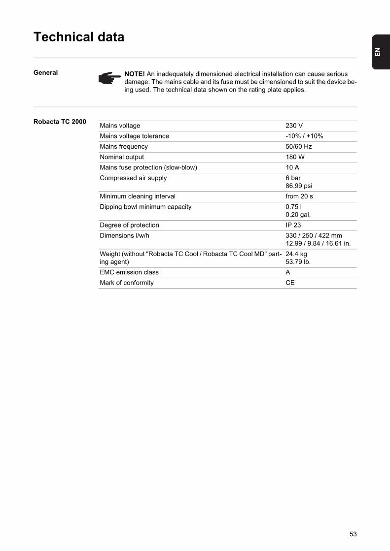
NOTE! An inadequately dimensioned electrical installation can cause serious damage. The mains cable and its fuse must be dimensioned to suit the device be-ing used. The technical data shown on the rating plate applies.
Mains voltage 230 V
Mains voltage tolerance -10% / +10%
Mains frequency 50/60 Hz
Nominal output 180 W
Mains fuse protection (slow-blow) 10 A
Compressed air supply 6 bar86.99 psi
Minimum cleaning interval from 20 s
Dipping bowl minimum capacity 0.75 l0.20 gal.
Degree of protection IP 23
Dimensions l/w/h 330 / 250 / 422 mm12.99 / 9.84 / 16.61 in.
Weight (without "Robacta TC Cool / Robacta TC Cool MD" part-ing agent)
24.4 kg53.79 lb.
EMC emission class A
Mark of conformity CE
53

54

Appendix
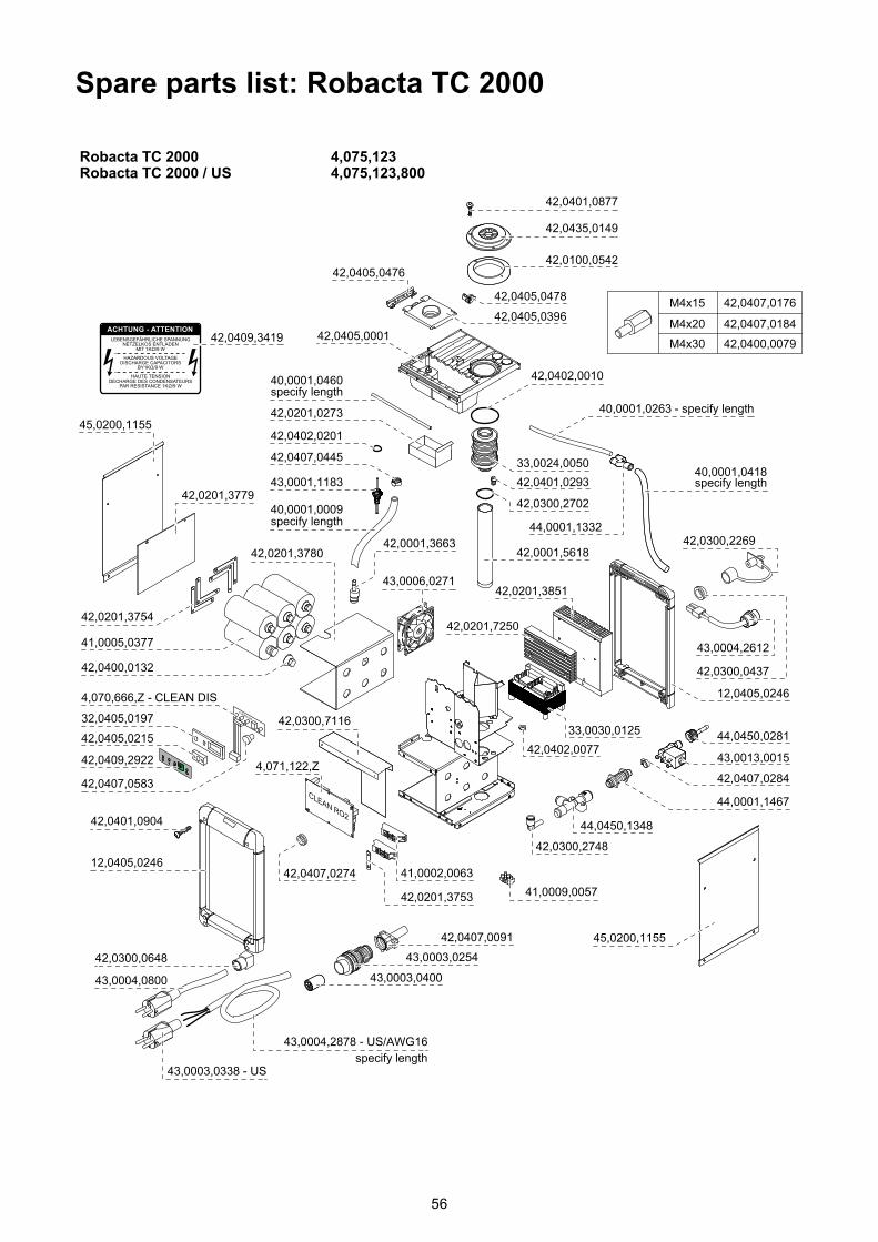
Spare parts list: Robacta TC 2000
56

57
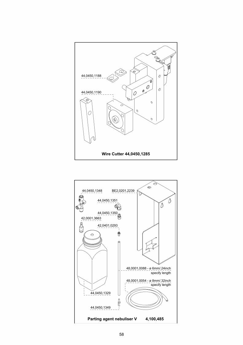
58

Maahantuonti ja myynti:
Pronius Oy
Keisarinviitta 20 B33960 Pirkkala
+358 (0)44 200 [email protected]