roadside hardware identification & inspection handbook
TRANSCRIPT

ROADSIDE HARDWARE
IDENTIFICATION & INSPECTION HANDBOOK
March 2019


LONGITUDINAL METAL BARRIERS General Inspection Checklist W-Beam Guardrail (Traffic Barrier Type 31)W-Beam GuardrailThrie Beam Guardrail Steel Box Beam Barrier – Retired Aluminum Box Beam Barrier – Retired

General Inspection Checklist
Longitudinal Metal Barriers
March 2019
RailRail is continuous. No vertical tears. No horizontal tears. No sections of flattened rail. No excessive deflection. No non-manufactured holes. Nominal height of rail is within tolerance. Offset from rail to curb meets standard. No mechanical fasteners or rectangular washers on face of rail (W-beam & thrie beam only). Rail is secured – no separation at posts.
Splices No missing bolts or bolts torn through rail. All bolts secure. Laps in direction of traffic (W-beam & thrie beam only). Splices in correct location.
Posts No missing posts. No broken/damaged posts. Post spacing is per Standard. Posts are plumb. No steel posts severely twisted. No tears in steel posts. Nuts/bolts secure. Leave-out area allows for post movement (when embedded in pavement) (W-beam & thrie beam only). No significant erosion around posts. Grading behind and in front of posts per Standard.

General Inspection Checklist
Longitudinal Metal Barriers
March 2019
Blockouts (W-Beam & Thrie Beam only)
No missing blockouts. No significant section loss. No twisted blockouts.
General All metallic components are free of significant rust or deterioration. All wooden materials free of deterioration, rot, excess damage. Obstacles are located beyond the working width. No slope-related lean of barrier. Nothing in front of barrier that could cause vehicle vaulting.

W-Beam (Traffic Barrier Type 31)
Longitudinal Metal Barriers
March 2019
Identification Details: 1. Rail height measured as noted in the MnDOT detail
"GUARDRAIL HEIGHT- FIELD MEASURING" to top of railis 31” (-1” to +2”).
2. Posts are I-shaped cross-section steel (W6x9 or W6x8.5).3. Steel post length is 6’-0” (or 9’-0” with 1:2 foreslope).
NOTE: All posts except "standard" 6' posts shall bestamped with the length per Std. Plate 8360A.
4. Post spacing is 6’-3” (Nominal).5. ½-Post (3’-1.5” spacing) and ¼-Post (1’-6.75” spacing)
allowed.6. Blockout size is 6” W x 12” D x 14” L.
NOTE: A minimum 8” to a maximum 24” blockout depthmay be used when underground obstructions areencountered.
7. Blockout may be wood or composite.8. Rail splices are mid-span for all standard 6’-3” post
spacing.9. Rail setback from face of curb to face of rail shall not
exceed 6”.10. Metal washers or metal prong reflectors not allowed.11. Standard Plan 690.

W-Beam Guardrail
Longitudinal Metal Barriers
March 2019
Identification Details:
1. Rail height measured as noted in the MnDOT detail"GUARDRAIL HEIGHT- FIELD MEASURING" to top of railis 27” (older versions) or 28” (newer versions) (-1” to +2”).
2. Post may be:a. Wood posts (Std. Plate 8307)
i. 6” x 8” (less common: 10” x 10”)ii. Length is 6’ 0”, 7’ 0”, 8’ 0”.
b. Steel posts (Std. Plate 8338)i. Posts are I-shaped cross-section steel (W6x9 or
W6x8.5).ii. Length is 6’-0” minimum.
3. Post spacing is 6’-3” (nominal).4. ½-Post (3’-1.5” spacing) allowed.5. Blockout material: wood or composite (less common:
steel).6. Wood blockout size is 6” W x 8” D x 14” L (less common:
10” W x 8” D x 14” L).7. Rail splices are at posts for all standard 6’-3” post spacing.8. Nesting of rail is permitted to stiffen a section of rail.9. Metal washers or metal prong reflectors are not allowed.

Thrie Beam Guardrail
Longitudinal Metal Barriers
March 2019
Identification Details:
1. Rail height as measured from nearest edge of pavedsurface (maximum 1’-0” in front) to top of rail is 32” (-2” to+2”).
2. Rail has 3 “bumps” on traffic side (vs. 2 on W-beamguardrail)
3. Posts are I-shaped cross-section steel (W6x9 or W6x8.5).4. Post spacing is 6’-3” (nominal).5. ½-Post (3’-1.5” spacing) allowed.6. Blockout may be wood or composite.7. Rail setback from face of curb to face of rail shall not
exceed 6”.8. Metal washers or metal prong reflectors not allowed.

Steel Box Beam Barrier - Retired
Longitudinal Metal Barriers
March 2019
Identification Details: 1. Rail height as measured from nearest edge of paved
surface to top of rail is 27”.NOTE: If adjacent to curb and setback of rail exceeds 36”to face of curb, the rail height shall be 27” as measuredfrom adjacent finished grade.
2. Rail is 6” x 8” x ¼” steel square-shaped box beam.3. Rail splices are mid-span for all standard 6’-3” post
spacing.4. Post is 3” I-shaped cross-section steel.5. Post length is 3’-0”.6. Post spacing is 6’-3” (nominal).7. Posts may be embedded or bolted to concrete structure.8. Retired Standard Plate 8320.

Aluminum Box Beam Barrier – Retired
Longitudinal Metal Barriers
March 2019
Identification Details:
1. Rail height as measured from nearest edge of pavedsurface to top of rail is 30”.NOTE: If adjacent to curb and setback of rail exceeds 36”to face of curb, the rail height shall be 30” as measuredfrom adjacent finished grade.
2. Rail is 6” x 11” extruded aluminum box beam with arounded top surface.
3. Rail splices are mid-span for all standard 6’-3” postspacing.
4. Post is 3” I-shaped cross-section steel or aluminum.5. Post length is 3’-0”.6. Post spacing is 6’-3” (Nominal).7. Posts may be embedded or bolted to concrete structure.8. Retired Standard Plate 8321.

END TERMINALS General Inspection Checklist
Trinity ET-Plus (Steel Post) ET-Plus (Wood Post) ET-2000 (Steel Post) ET-2000 (Wood Post) SRT-350 (6 Post Steel) SRT-350 (8 Post Wood) SRT-350 (6 Post Wood) SoftStop SRT M10
Road SKT-SP (2 Post) Systems SKT 350 (Steel Post)
SKT 350 (Wood Post) MSKT FLEAT-SP (2 Post) FLEAT 350 (Steel Post) FLEAT 350 (Wood Post) FLEAT-MT BEAT-BP BEAT-MT
Lindsay X-Lite – RetiredX-Tension
Non- ELT (Std. Plate 8329F-I) – Retired Proprietary BCT (Previous Std. Plate 8329A-E) –
Retired MELT Twisted End Treatment (Std. Plate 8319) – RetiredBuried in Backslope - Retired End Anchorage (Steel Post - Std. Plate 8338) End Anchorage (Wood Post - Std. Plate 8307) End Anchorage (Type 31) (Std. Plan 692)

General Inspection Checklist
End Terminals
March 2019
Rail Rail is continuous. Correct taper rate (if applicable). Correct parabolic shape (if applicable). No vertical tears. No horizontal tears. No sections of flattened rail (unless required by mfr). No excessive deflection. No non-manufactured holes. Nominal height of rail is within tolerance. Offset from rail to curb meets standard. No mechanical fasteners or rectangular washers on face of rail (unless required by manufacturer). Rail is secured – no separation at posts (at locations per Standard or manufacturer).
Splices No missing bolts or bolts torn through rail. All bolts secure. Laps in direction of traffic (unless required by mfr). Splices in correct location.
Posts No missing posts. No broken/damaged posts. Post spacing is per Standard or manufacturer. Posts are plumb. No steel posts severely twisted. No tears in steel posts. Nuts/bolts secure. Non-breakaway components are no more than 4” above ground (includes tubes for wood posts). Leave-out area allows for post movement (when embedded in pavement). No significant erosion around posts. Grading behind and in front of posts per Standard.
General Inspection Checklist
End Terminals
March 2019
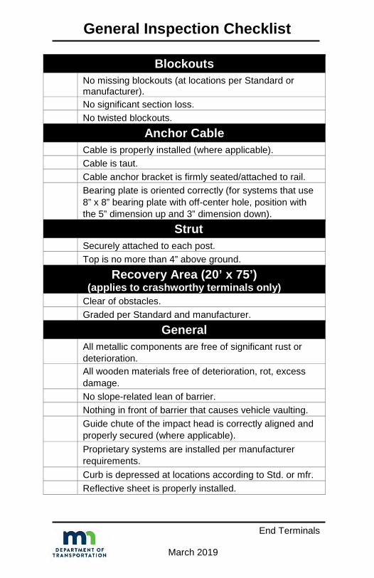
Blockouts No missing blockouts (at locations per Standard or manufacturer). No significant section loss. No twisted blockouts.
Anchor Cable Cable is properly installed (where applicable). Cable is taut. Cable anchor bracket is firmly seated/attached to rail. Bearing plate is oriented correctly (for systems that use 8” x 8” bearing plate with off-center hole, position with the 5” dimension up and 3” dimension down).
Strut Securely attached to each post. Top is no more than 4” above ground.
Recovery Area (20’ x 75’) (applies to crashworthy terminals only)
Clear of obstacles. Graded per Standard and manufacturer.
General All metallic components are free of significant rust or deterioration. All wooden materials free of deterioration, rot, excess damage. No slope-related lean of barrier. Nothing in front of barrier that causes vehicle vaulting. Guide chute of the impact head is correctly aligned and properly secured (where applicable). Proprietary systems are installed per manufacturer requirements. Curb is depressed at locations according to Std. or mfr. Reflective sheet is properly installed.

ET-Plus (Steel Post)
End Terminals
March 2019
Identification Details:
1. 1’-3” W x 2’-4” H Rectangular Impact head.
2. Front of impact head has flanges on sides only.
3. Rail is extruded out to the back as head slides along rail in end-on impact.
4. Impact head assembly has one strut on traffic side.
5. Breakaway cable assembly downstream of Post 1. 6. Cable anchor attaches to back of rail with six tabs
protruding through the rail. 7. Includes a ground strut assembly between Post 1 and
Post 2. 8. Post combinations:
a) Posts 1-8 – HBA. b) Post 1 – HBA, Posts 2-8 – Steel Yielding Terminal
Posts (SYTP). c) Posts 1 & 2 – Steel Hinged Breakaway (HBA), Posts
3-8 – Steel Line Posts.

ET-Plus (Steel Post)
End Terminals
March 2019
ET-Plus (8 HBA Post) – Inspection Checklist All items on the End Terminal – General Inspection Checklist plus the following: Posts 1-8 are proprietary HBA (hinged breakaway) posts. No blockouts on Posts 1 and 2. Rail panel is not attached to Post 2. Strut is attached to Post 1 and Post 2. Each rail panel is straight. Installed on straight taper over entire 50’-0” system length with offset between 0’ and 2’.
ET-Plus (1 HBA + 7 SYTP Post) – Inspection Checklist All items on the End Terminal – General Inspection Checklist plus the following: Post 1 is proprietary HBA (hinged breakaway) post. Posts 2 - 8 are proprietary SYTP (steel yielding) posts. No blockouts on Posts 1 and 2. Rail is attached at Post 2. Strut is attached to Post 1 and Post 2. Each rail panel is straight. Installed on straight taper over entire 50’-0” system length with offset between 0’ and 2’.
ET Plus (2 HBA Post) – Inspection Checklist All items on the End Terminal – General Inspection Checklist plus the following: Posts 1 & 2 are proprietary HBA (hinge breakaway) posts. Posts 3 through 8 are standard guardrail posts. No blockouts on Posts 1 and 2. Rail panel is not attached to Post 2. Strut is attached to Post 1 and Post 2. Each rail panel is straight. Installed on straight taper over entire 50’-0” system length with offset between 0’ and 2’.

ET-Plus (Wood Post)
End Terminals
March 2019
Identification Details:
1. 1’-3” W x 2’-4” HRectangular Impacthead.
2. Front of impact headhas flanges on sidesonly.
3. Rail is extruded out tothe back as head slidesalong rail in end-onimpact.
4. Impact head assembly has one strut on traffic side.5. Breakaway cable assembly downstream of Post 1.6. Cable anchor attaches to back of rail with six tabs
protruding through the rail.7. Includes a ground strut assembly between Post 1 and
Post 2.8. Posts 1 & 2 – Wood BCT in steel tube, Posts 3-8 –
Breakaway Wood.

ET-Plus (Wood Post)
End Terminals
March 2019
ET-Plus (Wood Post) – Inspection Checklist All items on the End Terminal – General Inspection
Checklist plus the following:
Posts 1 and Post 2 are BCT wood posts in steel tubes.
Posts 3 through 8 are breakaway wood posts. No blockouts on Posts 1 and 2. Rail is attached at Post 2. Strut is attached to Post 1 and Post 2.
Each rail panel is straight.
Installed on straight taper over entire 50’-0” system length with offset between 0’ and 2’.

ET-2000 (Steel Post)
End Terminals
March 2019
Identification Details: 1. 1’-8” W x 1’-8.5” H Square Impact head.2. Rail is extruded out to the back as head slides along rail in
end-on impact.3. Impact head assembly has one strut on traffic side.4. Breakaway cable assembly downstream of Post 1.5. Cable anchor attaches to back of rail with six tabs
protruding through the rail.6. Includes a ground strut assembly between Post 1 and
Post 2.7. Post combinations:
a) Posts 1-8 HBA.b) Post 1 – HBA, Posts 2-8 Steel Yielding Terminal Posts
(SYTP).

ET-2000 (Steel Post)
End Terminals
March 2019
ET-2000 (8 HBA Post) – Inspection Checklist All items on the End Terminal – General Inspection Checklist plus the following: Posts 1 through 8 are proprietary HBA (hinge breakaway) posts. No blockouts on Posts 1 and 2.
Rail panel is not attached to Post 2.
Strut is attached to Post 1 and Post 2.
Each rail panel is straight.
Installed on straight taper over entire 50’-0” system length with offset between 0’ and 2’.
ET-2000 (1 HBA + 7 SYTP Post) – Inspection Checklist
All items on the End Terminal – General Inspection Checklist plus the following:
Post 1 is proprietary HBA (hinge breakaway) post.
Posts 2 through 8 are proprietary SYTP (steel yielding) posts.
No blockouts on Posts 1 and 2.
Rail panel is attached to Post 2.
Strut is attached to Post 1 and Post 2.
Each rail panel is straight.
Installed on straight taper over entire 50’-0” system length with offset between 0’ and 2’.

ET-2000 (Wood Post)
End Terminals
March 2019
Identification Details:
1. 1’-8” W x 1’-8.5” H Square Impact head.2. Rail is extruded out to the back as head slides along rail in
end-on impact.3. Impact head assembly has one strut on traffic side.4. Breakaway cable assembly downstream of Post 1.5. Cable anchor attaches to back of rail with six tabs
protruding through the rail.6. Includes a ground strut assembly between Post 1 and
Post 2.7. Posts 1 & 2 – Wood BCT in steel tube, Posts 3-8
Breakaway Wood.

ET-2000 (Wood Post)
End Terminals
March 2019
ET-2000 (Wood Post) – Inspection Checklist All items on the End Terminal – General Inspection Checklist plus the following:
Post 1 and Post 2 are BCT wood posts in steel tubes.
Posts 3 through 8 are breakaway wood posts.
No blockouts on Posts 1 and 2.
Rail is attached at Post 2.
Strut is attached to Post 1 and Post 2.
Each rail panel is straight.
Installed on straight taper over entire 50’-0” system length with offset between 0’ and 1’.

SRT-350 (6 Post Steel)
End Terminals
March 2019
Identification Details: 1. Curved, buffered steel end section.2. W-beam rail has horizontal slots in first and second rail
segments.3. 37’-6” long in a straight-line flare.4. Upstream end has 4’ offset.5. Slot guard brackets attached to back of rail at downstream
end of slots (four total).6. Rail is not attached to Posts 2 through 5.7. No blockouts at Posts 1 & 2.8. Breakaway cable assembly downstream of Post 1.9. Cable anchor attaches to back of rail with eight bolts
through the rail.10. No bearing plate – uses cable anchor bracket within Post 1.11. Includes a ground strut assembly between Post 1 and
Post 2.12. Posts 1 – Steel Cable Release Post, Posts 2-6 – Steel
SYTP Posts.

SRT-350 (6 Post Steel)
End Terminals
March 2019
SRT-350 (6 Post Steel) – Inspection Checklist All items on the End Terminal – General Inspection Checklist plus the following:
Post 1 is proprietary CRT post.
No blockouts on Posts 1 and 2. Posts 2 through 6 are proprietary SYTP (steel yielding) posts.
Rail panels are not attached to Posts 2 through 5.
First and second rail segments have horizontal slots.
Slot guards installed downstream of slots with the deflector angle gap opening toward the elongated slots.
Each rail panel is straight.
Installed on straight taper over entire 37’-6” system length with offset of 4’.

SRT-350 (8 Post Wood)
End Terminals
March 2019
Identification Details:
1. Curved, buffered steel endsection.
2. W-Beam rail has horizontal slotsin first and second rail segments.
3. 37’-6” long in a parabolic curve.4. Upstream end has 4’ offset.5. Slot guard brackets attached to
back of rail at downstream endof slots (four total).
6. Rail is not attached to Posts 7 & 8.7. No blockouts at Posts 1 & 2.8. Breakaway cable assembly downstream of Post 1.9. Cable anchor attaches to back of rail with eight bolts
through the rail.10. V-notch bearing plate (notch faces up).11. Includes a ground strut assembly between Post 1 and
Post 2.12. Posts 1 & 2 – Wood BCT in steel tube, Posts 3-8 –
Breakaway Wood (CRT).

SRT-350 (8 Post Wood)
End Terminals
March 2019
SRT-350 (8 Post Wood) – Inspection Checklist All items on the End Terminal – General Inspection Checklist plus the following:
Post 1 and Post 2 are BCT wood posts in steel tubes.
No blockouts on Posts 1 and 2. Posts 1 and 2 have metal bands around them, under the post bolt hole. V-notch bearing plate installed with notch facing up.
Posts 3 through 8 are CRT wood posts.
Rail panels are not attached to Posts 7 and 8.
First and second rail segments have horizontal slots.
Slot guards installed downstream of slots with the deflector angle gap opening toward the elongated slots.
Each rail panel is curved.
Installed on parabolic over entire 37’-6” system length with offset of 4’.

SRT-350 (6 Post Wood)
End Terminals
March 2019
Identification Details:
1. Curved, buffered steel end section.2. W-Beam rail has horizontal slots in first and second rail
segments.3. 37’-6” long in a straight-line flare.4. Upstream end has 4’ offset.5. Slot guard brackets attached to back of rail at downstream
end of slots (four total).6. Rail is not attached to Post 2.7. No blockouts at Posts 1 & 2.8. Breakaway cable assembly downstream of Post 1.9. Cable anchor attaches to back of rail with eight bolts
through the rail.10. V-notch bearing plate (notch faces up).11. Includes a ground strut assembly between Post 1 and
Post 2.12. Posts 1 & 2 – Steel HBA, Posts 3-6 – Breakaway Wood
(CRT).

SRT-350 (6 Post Wood)
End Terminals
March 2019
SRT-350 (6 Post Wood) – Inspection Checklist All items on the End Terminal – General Inspection Checklist plus the following:
Post 1 and 2 are proprietary HBA posts.
No blockouts on Posts 1 and 2.
V-notch bearing plate installed with notch facing up.
Posts 3 through 6 are CRT wood posts.
Rail panels are not attached to Post 2.
First and second rail segments have horizontal slots.
Slot guards installed downstream of slots with the deflector angle gap opening toward the elongated slots.
Each rail panel is straight.
Installed on straight taper over entire 37’-6” system length with offset of 4’.
SoftStop
End Terminals
March 2019
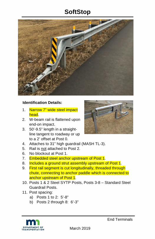
Identification Details:
1. Narrow 7” wide steel impacthead.
2. W-beam rail is flattened uponend-on impact.
3. 50’-9.5” length in a straight-line tangent to roadway or upto a 2’ offset at Post 0.
4. Attaches to 31” high guardrail (MASH TL-3).5. Rail is not attached to Post 2.6. No blockout at Post 1.7. Embedded steel anchor upstream of Post 1.8. Includes a ground strut assembly upstream of Post 1.9. First rail segment is cut longitudinally, threaded through
chute, connecting to anchor paddle which is connected toanchor upstream of Post 1.
10. Posts 1 & 2 Steel SYTP Posts, Posts 3-8 – Standard SteelGuardrail Posts.
11. Post spacing:a) Posts 1 to 2: 5’-8”b) Posts 2 through 8: 6’-3”

SoftStop
End Terminals
March 2019
SoftStop – Inspection Checklist All items on the End Terminal – General Inspection Checklist plus the following: Posts 1 and 2 are proprietary SYTP (steel yielding) posts.
Posts 3 through 8 are standard steel guardrail posts.
Rail is not bolted to Post 2.
Anchor post (Post 0) has a maximum height of 4” and a minimum height of 3.75” above finished grade.
No blockout on Post 1.
Top of rail height is 31”.
Strut is attached on non-traffic side with short leg down between Post 0 and Post 1.
Each rail panel is straight.
Installed on straight taper over entire 50’-9.5” system length with up to 2’ offset at Post 0.

SKT-SP (2 Post)
End Terminals
March 2019
Identification Details:
1. 1’-8” W x 1’-8.25” H Squareimpact head.
2. Rail is sequentially kinkedout to the back as headslides along rail in end-onimpact.
3. Impact head assembly has 2struts on traffic side.
4. Installed in a straight-linetaper – tangent to 25:1 allowed.
5. Breakaway cable assembly downstream of Post 1.6. Cable anchor attaches to back of rail with 8 bolts.7. No blockout at Posts 1 & 2.8. No ground strut assembly between Post 1 and Post 2.9. Posts 1 & 2 – Steel Hinged Posts, Posts 3-8 – Standard
Steel Guardrail Posts.

SKT-SP (2 Post)
End Terminals
March 2019
SKT-SP (2 Post) – Inspection Checklist All items on the End Terminal – General Inspection Checklist plus the following:
Rail is not attached to Post 1.
End rail panel has special slots.
Each rail panel is straight for 50’-0” system length.
Installed on straight taper with offset 0’ to 2’.
At Post 2 the open slot at post bolt faces Post 1.
Posts 3 through 8 are standard guardrail posts.
All post spacing at 6’-3”.

SKT 350 (Steel Post)
End Terminals
March 2019
Identification Details:
1. 1’-8” W x 1’-8.25” H Square impacthead.
2. Rail is sequentially kinked out tothe back as head slides along railin end-on impact.
3. Impact head assembly has 2 strutson traffic side.
4. Installed in a straight-line taper –tangent to 25:1 allowed.
5. Breakaway cable assemblydownstream of Post 1.
6. Cable anchor attaches to back ofrail with 8 bolts.
7. No blockout at Posts 1 & 2.8. Includes a ground strut assembly between Post 1 and
Post 2.9. Post combinations:
a) Posts 1&2 – Steel Hinged Posts, Posts 3-8 – PlugWeld Steel Posts.
b) Posts 1-8 – Steel Hinged Posts (shown in photos).c) Posts 1&2 – Plug Weld Steel post in steel tube, Posts
3-8 – Plug Weld Steel Posts.

SKT 350 (Steel Post)
End Terminals
March 2019
SKT 350 (Steel Post) – Inspection Checklist All items on the End Terminal – General Inspection Checklist plus the following:
Rail is not attached to Post 1.
End rail panel has special slots.
At Post 2 the open slot at post bolt faces Post 1.
Ground strut is attached to Posts 1 and 2.
Each rail panel is straight for 50’-0” system length.
Installed on straight taper with offset 0’ to 2’.

SKT 350 (Wood Post)
End Terminals
March 2019
Identification Details:
1. 1’-8” W x 1’-8.25” H Squareimpact head.
2. Rail is sequentially kinked outto the back as head slidesalong rail in end-on impact.
3. Impact head assembly has twostruts on traffic side.
4. Installed in a straight-line taper – tangent to 1:25 allowed.5. Breakaway cable assembly downstream of Post 1.6. Cable anchor attaches to back of rail with 8 bolts.7. No blockout at Posts 1 & 2.8. Includes a ground strut assembly between Post 1 and
Post 2.9. Post combinations:
a) Posts 1 & 2 – Steel Hinged, Posts 3-8 – BreakawayWood Posts (CRT).
b) Posts 1-8 – Breakaway Wood Post in steel tube (BCT).c) Posts 1 & 2 – Wood BCT in steel tube, Posts 3-8 –
CRT.d) Posts 1-4 – Wood BCT in steel tube, Posts 5-8 – CRT.

SKT 350 (Wood Post)
End Terminals
March 2019
SKT 350 (Wood Post) – Inspection Checklist All items on the End Terminal – General Inspection Checklist plus the following:
Rail is not attached to Post 1.
Ground strut is attached to Posts 1 and 2.
Each rail panel is straight for 50’-0” system length.
Installed on straight taper with offset 0’ to 2’.

MSKT
End Terminals
March 2019
Identification Details:
1. Square impact head.2. Rail is sequentially
kinked out to the backas head slides alongrail in end-on impact.
3. Impact head assemblyhas nearly solid panelon traffic side of therail.
4. Placed in straight-line taper – 1:25 or flatter.5. Second guardrail panel is 9’-4.5” long to get splices at
mid-span.6. Breakaway cable assembly downstream of Post 1.7. Cable anchor attaches to back of rail with eight bolts.8. No blockout at Posts 1 & 2.9. Attaches to 31” high guardrail (MASH TL-3).10. Includes a ground strut assembly between Post 1 and
Post 2.11. Posts 1 & 2 – Steel Hinged Posts, Posts 3-8 – Standard
Steel guardrail posts.
MSKT
End Terminals
March 2019
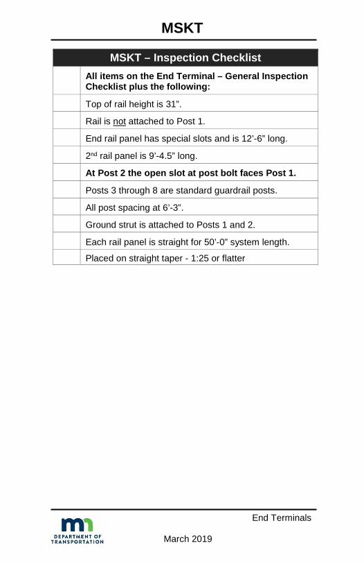
MSKT – Inspection Checklist All items on the End Terminal – General Inspection Checklist plus the following:
Top of rail height is 31”.
Rail is not attached to Post 1.
End rail panel has special slots and is 12’-6” long.
2nd rail panel is 9’-4.5” long.
At Post 2 the open slot at post bolt faces Post 1.
Posts 3 through 8 are standard guardrail posts.
All post spacing at 6’-3”.
Ground strut is attached to Posts 1 and 2.
Each rail panel is straight for 50’-0” system length.
Placed on straight taper - 1:25 or flatter

FLEAT-SP (2 Post)
End Terminals
March 2019
Identification Details:
1. Rectangular impact head - flanges all sides.2. Square bar on top of impact head.3. Rail is sequentially kinked out to the front as head slides
along rail in end-on impact.4. Impact head assembly has two struts on traffic side of rail.5. Installed in a straight-line taper – 2.5’ to 4’ offset at
upstream end.6. Rail not attached to Post 1 or to Post 3.7. Breakaway cable assembly downstream of Post 1.8. Cable anchor attaches to back of rail with 8 bolts.9. Cable not inside feeder chute.10. No blockout at Posts 1 & 2.11. No ground strut assembly between Post 1 and Post 2.12. Posts 1 & 2 – Steel Hinged Posts, Posts 3-7 – Standard
Steel Guardrail Posts.

FLEAT-SP (2 Post)
End Terminals
March 2019
FLEAT-SP (2 Post) – Inspection Checklist All items on the End Terminal – General Inspection Checklist plus the following:
Rail is not attached to Post 1 or to Post 3.
End rail panel has special slots.
Each rail panel is straight for 37’-6” system length.
Installed on straight taper with offset 2’-6” to 4’-0”.
At Post 2 the open slot at post bolt faces Post 1. Posts 3 through 6 are standard guardrail posts.
All post spacing at 6’-3”.

FLEAT 350 (Steel Post)
End Terminals
March 2019
Identification Details:
1. Rectangular impact head - flangesall sides.
2. Square bar on top of impact head.3. Rail is sequentially kinked out to the
front in end-on impact.4. Impact head assembly has 2 struts
on traffic side.5. Installed in a straight-line taper – 2’-6” to 4’-0” offset at
upstream end.6. Rail not attached to Post 1 or to Post 3.7. Breakaway cable assembly downstream of Post 1.8. Cable anchor attaches to back of rail with 8 bolts.9. Cable not inside feeder chute.10. No blockout at Posts 1 & 2.11. Includes a ground strut assembly between Post 1 and
Post 2.12. Post combinations:
a) Posts 1 & 2 – Steel Hinged Posts, Posts 3-7 – PlugWeld Steel Posts.
b) Posts 1-7 – Steel Hinged Posts.c) Posts 1 & 2 – Plug Weld Steel Post in steel tube,
Posts 3-7 – Plug Weld Steel Posts.

FLEAT 350 (Steel Post)
End Terminals
March 2019
FLEAT 350 (Steel Post) – Inspection Checklist All items on the End Terminal – General Inspection Checklist plus the following:
Rail is not attached to Post 1 or to Post 3.
At Post 2 the open slot at post bolt faces Post 1.
Ground strut is attached to Posts 1 and 2.
Each rail panel is straight for 37’-6” system length.
Installed on straight taper with offset 2’-6” to 4’-0”.

FLEAT 350 (Wood Post)
End Terminals
March 2019
Identification Details:
1. Rectangular impact head -flanges all sides.
2. Square bar on top of impacthead.
3. Rail is sequentially kinkedout to the front as headslides along rail in end-onimpact.
4. Impact head assembly hastwo struts on traffic side of rail.
5. Installed in a straight-line taper – 2’-6” to 4’-0” offset atupstream end.
6. Rail not attached to Post 1 or to Post 3.7. Breakaway cable assembly downstream of Post 1.8. Cable anchor attaches to back of rail with 8 bolts.9. Cable not inside feeder chute.10. No blockout at Posts 1 & 2.11. Includes a ground strut assembly between Post 1 and
Post 2.12. Post combinations:
a) Posts 1 & 2 – Steel Hinged, Posts 3-7 – BreakawayWood Posts (CRT).
b) Posts 1&2 – Wood BCT in steel tube, Posts 3-7 –Breakaway Wood (CRT).
c) Older system could have 8 posts similar to (a) withPosts 3-8 Breakaway Wood (CRT).

FLEAT 350 (Wood Post)
End Terminals
March 2019
FLEAT 350 (Wood Post) – Inspection Checklist All items on the End Terminal – General Inspection Checklist plus the following:
Rail is not attached to Post 1 or to Post 3.
Posts 1 and 2 are installed in foundation tubes.
Ground strut is attached to Posts 1 and 2.
Each rail panel is straight for 37’-6” system length.
Installed on straight taper with offset 2’-6” to 4’-0”.

FLEAT-MT
End Terminals
March 2019
Identification Details:
1. Rectangular impact heads- flanges all sides.
2. Square bar on top ofimpact heads.
3. Rail is not attached to Post1 or to Post 3.
4. Rail is sequentially kinkedout to the front as headslides along rail in end-onimpact.
5. Impact head assemblies have 2 struts on traffic side of rail.6. Installed in a median.7. Post 1 through 4 installed at a straight-line taper (2’-0”
offset for upstream head).8. Breakaway cable assembly downstream of Post 1.9. Breakaway cable assembly downstream of Post 4 (for
second head).10. Each cable anchor attaches to back of rail with 8 bolts.11. Cable not inside feeder chute (for each head).12. No blockout at Posts 1 & 2.13. Ground strut assembly between Post 1 and Post 2.14. Posts 1, 2 & 4 – Wood BCT in steel tube, Posts 3, 5-7 –
Breakaway Wood (CRT).

FLEAT-MT
End Terminals
March 2019
FLEAT-MT – Inspection Checklist All items on the End Terminal – General Inspection Checklist plus the following:
Rail is not attached to Post 1 or to Post 3.
Each rail panel is straight within 37’-6” system length. Installed on straight taper with offset 2’-0” beginning at Post 4. Rail is not attached to post at the impact head side only at Post 4. Deflector box is secured behind the anchor bracket near Post 2.
Post breaker is attached on the non-traffic side of Post 1.
Tether cable is looped around impact head at Post 1, looped around the anchor cable near Post 2 and tied under the impact head at Post 1.

BEAT-BP
End Terminals
March 2019
Identification Details:
1. Rectangular impact heads withflanges on all sides.
2. Impact head causes the 6"x 6"box beam rail sections to burstwhen impacted end-on.
3. Installed in a median to shieldbridge piers.
4. Breakaway steel posts supportrail with a bracket and ablockout tube (in photo).
5. Cable assembly downstreamof Post 1.

BEAT-BP
End Terminals
March 2019
BEAT-BP – Inspection Checklist All items on the End Terminal – General Inspection Checklist plus the following:
Top of rail height of 6” x 6” box beam is 2’-4”.
At least 8” is provided from backside of posts to object being shielded.
End tube section is bolted to second rail tube.
Posts 1 through 6 on each end are breakaway.
Box beam tubing is securely attached to rail support brackets.
Rail support brackets are securely attached to posts.
The post breaker is on the approach back side of Post 1.
The tether cable is attached to restrain the impact head.
The impact head is properly inserted into the end tube section with the large triangular gusset plates facing down. The bottom of the impact head is approximately 12” above ground.
BEAT-MT
End Terminals
March 2019
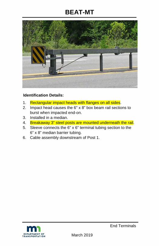
Identification Details:
1. Rectangular impact heads with flanges on all sides.2. Impact head causes the 6" x 8” box beam rail sections to
burst when impacted end-on.3. Installed in a median.4. Breakaway 3” steel posts are mounted underneath the rail.5. Sleeve connects the 6” x 6” terminal tubing section to the
6” x 8” median barrier tubing.6. Cable assembly downstream of Post 1.

BEAT-MT
End Terminals
March 2019
BEAT-MT – Inspection Checklist All items on the End Terminal – General Inspection Checklist plus the following:
Top of rail height of 6” x 6” box beam is 2’-4”.
End tube section is bolted to second rail tube. Box beam tubing is securely attached to rail support brackets.
Rail support brackets are securely attached to posts.
The post breaker is on the non-traffic side of Post 1.
The tether cable is attached to restrain the impact head.
The impact head is properly inserted into the end tube section with the large triangular gusset plates facing down. The bottom of the impact head is approximately 12” above ground.

X-Lite – Retired
End Terminals
March 2019
Identification Details:
1. Rectangular impact headwith flanges on sidesonly.
2. W-beam rail telescopesrearward in end-onimpact.
3. Installed in a straight-linetaper or tangent to roadway.
4. Rail not attached to Posts 3 & 5.5. Shear bolts used at Posts 5 & 7.6. Breakaway cable assembly downstream of Post 2.7. Cable anchor attaches to back of rail immediately upstream
of Post 3.8. No blockout at Posts 1 & 2.9. Includes two ground strut tension rods between Post 1 and
Post 2.10. Posts 1, 2 & 3 – Special Steel Posts, Posts 4-8 – Standard
Steel Guardrail Posts.

X-Lite – Retired
End Terminals
March 2019
X-Lite – Retired – Inspection ChecklistAll items on the End Terminal – General Inspection Checklist plus the following:
Rail not bolted to Posts 3 and 5.
Rail bolted at Posts 1, 2, 4, 6, 7, and 8.
Square washer used at Post 1.
At Post 2, rail bolted using trailing slot on post. At Posts 1, 4, and 6, rail bolted using approach hole on posts. Rails at Post 5 and Post 7 spliced using special yellow shear bolts. At Post 7, the 10” bolt passes through both rails, blockout and post. Slider assembly has bolts from back to front with nuts on the traffic side. Angled position of slider panel points toward back end of system. Arrows on slider point towards the front of the system.
Cable bracket and washer installed on cable at Post 2.
No blockout on Post 1 or Post 2.
Installed on straight taper over entire 50’-0” system length with offset from 0’ to 1’.

X-Tension
End Terminals
March 2019
Identification Details:
1. Impact head withplastic nose piece.
2. W-beam railtelescopes rearwardin end-on impact.
3. Installed in a straight-line taper (0’ to 4’ offset).4. Rail not attached to Post 3.5. Shear bolts used at Post 5.6. Tension cable assembly upstream of Post 1.7. Cables run along back of rail and attach to back of rail
immediately upstream of Post 7.8. No blockout at Post 1.9. Includes ground strut assembly upstream of Post 1.10. Post Combinations:
a) Post 1 – Special Steel Post, Post 2 – Crimped Steel(weakened), Posts 3-8 – Standard Steel GuardrailPosts.
b) Post 1 – Special Steel Post, Posts 2-6 – BreakawayWood Posts (CRT).

X-Tension
End Terminals
March 2019
X-Tension – Inspection ChecklistAll items on the End Terminal – General Inspection Checklist plus the following:
Rail is not attached to Post 3.
Strut lays flush on the ground upstream of Post 1. Front of strut should be level or lower at the anchor end than at the post end.
Slider panel is connected to end of first rail with all 4 holes bolted with nuts on traffic face.
Slider bracket affixed to back of rail 2 with four bolts and nuts on backside of rail.
Angle bar is fitted closest to impact head end.
Yellow shear bolts installed at Post 5.
Posts 3 through 6 are standard guardrail posts (or timber CRT posts).
Installed on straight taper over entire 37’-6” system length with offset from 0’ to 4’.

Eccentric Loader Terminal (ELT) (Std. Plate 8329F-I) – Retired
End Terminals
March 2019
Identification Details:
1. Round corrugated steel pipenose assembly (top viewshown at right); 24” diametersteel pipe – 24” high.
2. 37’-6”’ long in a paraboliccurve.
3. Upstream end has 4’ offset.4. No blockout at Post 1.5. Rail is not attached to Posts 2 through 6.6. Breakaway cable assembly downstream of Post 1.7. Cable anchor attaches to back of rail with eight bolts
upstream of Post 2.8. Includes ground strut assembly between Post 1 and Post 2.9. Post Spacing: 1 to 3: 6’-3”; 3 to 6: 4’-2”; 6 to 8: 6’-3”.10. Posts 1 & 2 – Wood BCT in steel tube, Posts 3-7 –
Breakaway Wood (CRT).

Eccentric Loader Terminal (ELT) (Std. Plate 8329F-I) – Retired
End Terminals
March 2019
ELT – Inspection Checklist All items on the End Terminal – General Inspection Checklist plus the following:
Design speed for roadway is less than 45 mph.
Height of device is at least 27”.
No blockout on Post 1.
Strut is attached to Post 1 and Post 2.
Posts 1 and 2 are wood BCT in steel tube.
Rail is not attached at Posts 2 through 6.
Each rail panel is curved.
Installed on parabolic curve over entire 37-6” system length with offset of 4’.

Breakaway Cable Terminal (BCT) (Std. Plate 8329A-E) – Retired
End Terminals
March 2019
Identification Details:
1. Rounded steel bufferedend assembly:a) Empty when viewed
from top if offset is 4’.b) Includes diaphragms
when offset less than 4’.2. 37.5’ long in a parabolic curve.3. Upstream end has 4’ offset.4. No blockout at Posts 1& 2.5. Breakaway cable assembly downstream of Post 1.6. Cable anchor attaches to back of rail with eight bolts
upstream of Post 2.7. No ground strut assembly between Post 1 and Post 2.8. Post spacing: 6’-3”.9. Post Combinations:
a) Posts 1 & 2 – Wood BCT in steel tube.b) Posts 1 & 2 – Wood post in concrete foundation.

Modified Eccentric Loader Terminal (MELT)
End Terminals
March 2019
Identification Details:
1. Rounded steel bufferedend assembly with twodiaphragm plates(could be bolted orwelded).
2. 37’-6” long in aparabolic curve.
3. Upstream end has 4’ offset.4. Rail is not attached to Posts 2 - 6.5. No blockout at Post 1.6. Can only be used when speed is less than 45 mph.7. Breakaway cable assembly downstream of Post 1.8. Cable anchor attaches to back of rail with eight bolts
upstream of Post 2.9. Includes ground strut assembly between Post 1 and
Post 2.10. Post Spacing: 1 to 3: 6’-3”; 3 to 6: 4’-2”; 6 to 8: 6’-3”.11. Posts 1 & 2 – Wood BCT in steel tube, Posts 3-6 –
Breakaway Wood (CRT), Posts 7-8 – Standard WoodGuardrail Posts.

Twisted End Treatment (Std. Plate 8319) – Retired
End Terminals
March 2019
Identification Details:
1. Upstream end of guardrailnot exposed.
2. 25’ long, using one railsegment.
3. Rail is vertical atdownstream end andhorizontal at upstream end.
4. Flared end section atupstream end that is buried.

Buried in Backslope – Retired
End Terminals
March 2019
Identification Details:
1. Upstream end ofguardrail notexposed.
2. Rail height abovepavement remainsconstant.

End Anchorage (Steel Post – Std. Plate 8338)
End Terminals
March 2019
Identification Details:
1. Flared end section (“fishtail” or “spoon”).2. One 12’-6” section of rail (or downstream end of 25’ section
of rail).3. Cable assembly upstream of last post (more recent
versions).4. Downstream end of anchor rod assembly buried with
concrete anchor block (older versions).5. Includes ground strut assembly between last post and 2nd
last post (more recent versions).6. Cable anchor attaches to back of rail with 8 bolts
downstream of 2nd last post (strut anchorage assembly).7. Anchorage bolt attaches to bottom of rail (buried anchorage
assembly).8. No blockout on last two posts (strut anchorage assembly).9. Blockout on last two posts (buried anchorage assembly).10. HBA steel guardrail posts (hinged breakaway).

End Anchorage (Steel Post – Std. Plate 8338)
End Terminals
March 2019
End Anchorage (Steel Post – Std. Plate 8338A-D) Inspection Checklist
(Buried Anchorage Assembly)All items on the End Terminal – General Inspection Checklist plus the following:
Device is not in a location where it can be hit head-on.
Anchorage bolt securely attached to bottom of guardrail with anchorage plate and anchorage plate washer on inside face of rail.
Turnbuckle between anchorage bolt and anchor rod has full thread contact on both ends.
Last two posts are breakaway steel posts.
Post spacing is 6’-3”.
Last two posts have blockouts.
Area directly behind the device (12’-6” length) and downstream of the device is clear of obstacles.
End Anchorage (Steel Post – Std. Plate 8338C-D) Inspection Checklist
(Strut Anchorage Assembly)All items on the End Terminal – General Inspection Checklist plus the following:
Device is not in a location where it can be hit head-on.
Ground strut is attached to last two posts.
Last two posts are breakaway steel posts.
Post spacing is 6’-3”.
No blockouts on last two posts.
Area directly behind the device (12’-6” length) and downstream of the device is clear of obstacles.

End Anchorage (Wood Post – Std. Plate 8307)
End Terminals
March 2019
Identification Details:
1. Flared end section (“fishtail” or “spoon”).2. One 12’-6” section of rail (or downstream end of 25’ section
of rail).3. Cable assembly upstream of last post (more recent
versions).4. Downstream end of anchor rod assembly buried with
concrete anchor block (older versions).5. No cable assembly (original versions).6. Includes ground strut assembly between last post and 2nd
last post (more recent versions).7. Cable anchor attaches to back of rail with eight bolts
downstream of 2nd last post (strut anchorage assembly).8. Anchorage bolt attaches to bottom of rail (buried anchorage
assembly).9. No blockout on last post (strut anchorage assembly).10. Blockouts on last 2 posts (buried anchorage assembly).11. Posts:
a) Wood BCT in steel tube (newer versions).b) Standard wood guardrail posts (older versions).

End Anchorage (Wood Post – Std. Plate 8307)
End Terminals
March 2019
End Anchorage (Wood Post – Std. Plate 8307D-S) Inspection Checklist
(Buried Anchorage Assembly)All items on the End Terminal – General Inspection Checklist plus the following:
Device is not in a location where it can be hit head-on.
Anchorage bolt securely attached to bottom of guardrail with anchorage plate and anchorage plate washer on inside face of rail.
Turnbuckle between anchorage bolt and anchor rod has full thread contact on both ends.
Last two posts - breakaway wood posts in steel tubes.
Post spacing is 6’-3”.
Last two posts have blockouts.
Area directly behind the device (12’-6” length) and downstream of the device is clear of obstacles.
End Anchorage (Wood Post – Std. Plate 8307R-S) Inspection Checklist
(Strut Anchorage Assembly)All items on the End Terminal – General Inspection Checklist plus the following:
Device is not in a location where it can be hit head-on.
Ground strut is attached to last two posts.
Last two posts - breakaway wood posts in steel tubes.
Post spacing is 6’-3”.
No blockout on last post.
Area directly behind the device (12’-6” length) and downstream of the device is clear of obstacles.

End Anchorage (Type 31) (Std. Plan 692)
End Terminals
March 2019
Identification Details:
1. Curled end section.2. End rail beam is 26’-0.5” long, which extends to splice
located between 4th and 5th last post (or 13’-6.5” long,which extends to splice located between 2nd and 3rd lastpost). Rail and end section extend approximately 4’downstream from center of last post).
3. Attaches to Traffic Barrier Type 31 (31” high W-beamguardrail).
4. Post spacing is 6’-3”.5. Cable assembly upstream of last post.6. Cable anchor attaches to back of rail with 8 bolts
downstream of 2nd last post.7. Includes ground strut assembly between last post and 2nd
last post.8. No blockout on last 2 posts.9. Posts: Wood BCT in steel tube.

End Anchorage (Type 31) (Std. Plan 692)
End Terminals
March 2019
End Anchorage (Type 31) – Inspection Checklist All items on the End Terminal – General Inspection Checklist plus the following:
Device is not in a location where it can be hit head-on.
Device is 31” high.
Ground strut is attached to last two posts.
Last two posts are BCT wood post in steel tubes.
Post spacing is 6’-3”.
No blockouts on last two posts.
End rail beam is either 26’-0.5” or 13’-6.5”. Rail and end section extend approximately 4’ downstream from center of last post.
Area downstream from and behind the 5th last post from downstream end of the device is clear of obstacles.


CABLE BARRIERS General Inspection Checklist High Tension (Brifen TL4 - 4-Cable)
High Tension (Gibraltar TL4 - 3-Cable)
High Tension (Gibraltar TL4 - 4-Cable)
High Tension (Trinity CASS-S3 TL4 - 3-Cable)
High Tension (Trinity CASS-S3 TL4 - 4-Cable)
Low Tension (Std. Plates 8330/8331)

General Inspection Checklist
Cable Barriers
March 2019
CableCable is continuous.
No broken strands, no damage.
No loss of tension.
Minimal horizontal deflection.
Minimal sag between posts.
Nominal height of top cable is within tolerance (per Standard or manufacturer).
Offset from cable to curb meets Standard.
Cable is secured to posts (per Standard or manufacturer).
Splices Turnbuckles have adequate threads for tensioning.
Splices in correct location—not at post.
Posts No missing posts.
No broken/damaged posts.
Post spacing is per Standard or manufacturer.
Posts are plumb.
Nuts/bolts secure.
No significant erosion around posts.
Grading behind and in front of posts per Standard.

General Inspection Checklist
Cable Barriers
March 2019
Anchors Non-breakaway components are no more than 4” above ground. Not pulling out of the ground.
No significant erosion around posts/anchors.
Graded per Standard and manufacturer.
For anchors on upstream end of system, area behind and downstream of anchor is clear of obstacles.
General All metallic components are free of significant rust or deterioration.
All wooden materials free of deterioration, rot, excess damage.
Obstacles are located beyond deflection distance.
No slope-related lean of barrier.
Nothing in front of barrier that could cause vehicle vaulting. Proprietary systems are installed per manufacturer requirements. Reflective sheeting or delineation is properly installed.

High Tension (Brifen TL4 - 4 – Cable)
Cable Barriers
March 2019
Identification Details:
1. Interwoven cablesaround posts.
2. Posts can be in socketor driven.
3. Z-shaped posts cross-section (4” x 1.25”).
4. Terminal consists ofone anchor and fourposts.
5. Four cables into one concrete anchor at each terminal.

High Tension (Brifen TL4 - 4 – Cable)
Cable Barriers
March 2019
High Tension (Brifen TL4 – 4-Cable) Inspection Checklist
Anchors
Anchor set at 12° angle. (+3°, ‐1°) A Post set at proper angle. 79° angle (± 4°) from horizontal. Cables DO NOT WEAVE between the anchor and A Post.
Weakening cuts are facing the anchor.
Retainer pin properly installed.
Tensile rod nuts have minimum 3 threads exposed. Plastic washer is between anchor plate and steel washer.
Mechanical fitting has four or FEWER threads showing (trailing anchor, typically).
No damage that would affect the performance.
Length of Need
Cables are woven properly.
Turnbuckles are properly threaded (1.5” minimum).
Fence is at the proper tension (+/‐ 20%). Posts are oriented in the proper direction. Roll facing traffic. No damage that would affect the performance.
Post spacing is per plan.

High Tension (Gibraltar TL4 - 3 – Cable)
Cable Barriers
March 2019
Identification Details:
1. All cables on same side of eachpost.
2. Cables alternate sides from post topost.
3. Posts can be in socket or driven.4. C-channel shaped posts (3.25” x
2.5”).5. Terminal consists of one anchor
and four posts.6. Three cables into one anchor at
each terminal.

High Tension (Gibraltar TL4 - 3 – Cable)
Cable Barriers
March 2019
High Tension (Gibraltar TL4 - 3-Cable) Inspection Checklist
All items on the Cable Barriers – General Inspection Checklist plus the following:
Height of top cable is 39” (+/- 1”) (applies to 3-cable and 4-cable system).
On line posts, hairpin clip does not extend above top of C-section posts.
Terminal posts have hook part of J-bolt on closed side of C-section post.
Anchor terminal fittings (threads on end of cable) extend 3.5” min. beyond nut.
Terminal keeper wire is in place across threads.
Terminal Post 1 (post closest to anchor post) is tilted towards anchor post at 10:1 (V:H).

High Tension (Gibraltar TL4 - 4 – Cable)
Cable Barriers
March 2019
Identification Details:
1. All cables on same side of eachpost.
2. Cables alternate sides from post topost.
3. Posts can be in socket or driven.4. C-channel shaped posts (3.25” x
2.5”).5. Terminal consists of one anchor
and four posts.6. Four cables into one anchor at
each terminal.

High Tension (Gibraltar TL4 - 4 – Cable)
Cable Barriers
March 2019
High Tension (Gibraltar TL4 - 4-Cable) Inspection Checklist
All items on the Cable Barriers – General Inspection Checklist plus the following:
Height of top cable is 39” (+/- 1”) (applies to 3-cable and 4-cable system).
On line posts, hairpin clip does not extend above top of C-section posts.
Terminal posts have hook part of J-bolt on closed side of C-section post.
Anchor terminal fittings (threads on end of cable) extend 3.5” minimum beyond nut.
Terminal keeper wire is in place across threads.
Terminal Post 1 (post closest to anchor post) is tilted towards anchor post at 10:1 (V:H).

High Tension (Trinity CASS-S3 TL4 - 3 – Cable)
Cable Barriers
March 2019
Identification Details:
1. All cables fit in slots of posts.2. Posts can be in socket or driven.3. I-shaped post cross-section.4. Terminal consists of three anchors and six posts.5. Three cables into three separate anchors at each terminal.

High Tension (Trinity CASS-S3 TL4 - 3 – Cable)
Cable Barriers
March 2019
High Tension (Trinity CASS-S3 TL4 - 3-Cable) Inspection Checklist
All items on the Cable Barriers – General Inspection Checklist plus the following:
Height of top cable is 38.25” (+/- 1”) (3-cable system).
On line posts, each hook bolt is securely attached with nut.
End of cable at each terminal post is secured with two nuts.

High Tension (Trinity CASS-S3 TL4 - 4 – Cable)
Cable Barriers
March 2019
Identification Details: 1. Top two cables fit in slots of
posts.2. Bottom two cables along
alternate sides of posts.3. Posts can be in socket or
driven.4. I-shaped post cross-
section.5. Terminal consists of four
anchors and six posts.6. Four cables into four separate anchors at each terminal.

High Tension (Trinity CASS-S3 TL4 - 4 – Cable)
Cable Barriers
March 2019
High Tension (CASS-S3 TL4 - 4-Cable) Inspection Checklist
All items on the Cable Barriers – General Inspection Checklist plus the following:
Height of top cable is 42.25” (+/- 1”) (4-cable system).
On line posts, each hook bolt is securely attached with nut.
End of cable at each terminal post is secured with two nuts.

Low Tension (Standard Plate 8330)
Cable Barriers
March 2019
Identification Details: 1. Three cables attached to same
side of posts.2. Cables are 4” apart.3. 4.75” to 6.25” diameter wood post
(Std. Plate 8330).4. 12’-6” post spacing.5. 28” to top of top cable.6. Terminal consists of:
a) One steel anchor post andanchor angle set in concrete(Std. Plate 8333).
b) One wood post and anchorrod with anchor block(Retired Std. Plates 8313Band 8314B) (shown in photo).

Low Tension (Standard Plate 8331)
Cable Barriers
March 2019
Identification Details: 1. Three cables attached to same
side of posts.2. Cables are 3” apart.3. S3 x 5.7 I-beam or flanged
channel steel post (Std. Plate8331).
4. 12’-6” post spacing.5. 27” to top of top cable.6. Terminal consists of one steel
anchor post and anchor angleset in concrete (Std. Plate8333).


CRASH CUSHIONS General Inspection Checklist Bullnose (Wood Post - Std. Plan 611) Bullnose (Wood Post - Std. Plan 601) - Retired Bullnose (Steel Post) SCI Smart Cushion Brakemaster 350 CAT-350 QuadGuard QuadGuard II QuadGuard Elite HEART REACT 350 X-MASUniversal TAU-II Universal TAU-II-R Compressor

General Inspection Checklist (except Bullnose)
Crash Cushions
March 2019
GeneralNo vertical tears in rail or side panels. No horizontal tears in rail or side panels. No sections of flattened rail or side panels. Fender panels and transition panels are nested tightly against system. Nominal height of device is within tolerance. Offset from device to curb meets standard. No missing bolts or other hardware. Laps in direction of traffic. No missing or damaged posts, legs or supports. Posts are plumb. Nuts/bolts secure.
Non-breakaway components are no more than 4” above ground.
No significant erosion around device. Grading behind and in front of posts per manufacturer requirements.
All metallic components are free of significant rust or deterioration.
All wooden materials free of deterioration, rot, excess damage.
Support structure is anchored per manufacturer’s requirements to a specified concrete pad.
Concrete anchor bolts are secure.
Nothing in front of device that could cause vehicle vaulting. Cartridges (or similar crushable parts) are not damaged. HDPE components do not have significant permanent deformation.

Bullnose (Wood Post - Std. Plan 611)
Crash Cushions
March 2019
Identification Details:
1. Rails are thrie beam.2. Thrie beam rail is slotted longitudinally from front to Post 8
on each side.3. Tensioning cable downstream of Post 1 on each side.4. Thrie beam to W-beam rail transition after Post 10 on each
side.NOTE: System may anchor to a structure. In these cases,appropriate transitions to structure per MnDOT standardswould be utilized after the W-beam transition.
5. 10 posts on each side:a) Posts 1 and 2 are wood post in steel tube (BCT).b) Posts 3 through 8 are breakaway wood posts (CRT).c) Posts 9 and 10 are standard wood guardrail posts.

Bullnose (W-Beam) Retired
Crash Cushions
March 2019
Identification Details:
1. Rails are W-beam.2. Posts are wood and spaced at 6’-3”.3. Blockouts are wood.4. Rail splices are at posts.5. No breakaway or special posts.

Bullnose (Steel Post) (Currently being tested)
Crash Cushions
March 2019
Identification Details:
1. Rails are thrie beam.2. Thrie beam rail is slotted longitudinally
from front to Post 8 on each side.3. Tensioning cable downstream of Post 1
on each side.4. Thrie beam to W-beam rail transition
after Post 10 on each side.NOTE: System may anchor to astructure. In these cases, appropriatetransitions to structure per MnDOTstandards would be utilized after the W-beam transition.
5. 10 posts on each side:a) Posts 1 and 2 are wood post in steel tube (BCT).b) Posts 3 through 8 are breakaway fracturing bolt posts.c) Posts 9 and 10 are standard steel guardrail posts.

Bullnose (Wood and Steel Post)
Crash Cushions
March 2019
Bullnose (Wood and Steel Post) – Inspection Checklist
Rail Rail is continuous. No vertical tears. No horizontal tears. No sections of flattened rail. No excessive deflection. No non-manufactured holes. Nominal height of rail is within tolerance. Offset from rail to curb meets standard.
No mechanical fasteners or rectangular washers on face of rail. Rail is secured – no separation at posts.
Splices No missing bolts or bolts torn through rail.
All bolts secure.
Laps in direction of traffic.
Splices in correct location.
Posts No missing posts.
No broken/damaged posts.
Post spacing is per Standard.
Posts are plumb.
No steel posts severely twisted.
No tears in steel posts.
Nuts/bolts secure. Non-breakaway components are no more than 4” above ground (includes tubes for wood posts).

Bullnose (Wood and Steel Post)
Crash Cushions
March 2019
Bullnose (Wood and Steel Post) – Inspection ChecklistPosts (cont.)
Leave-out area allows for post movement (when embedded in pavement). No significant erosion around posts. Grading behind and in front of posts per Standard.
Blockouts No missing blockouts (at locations per Standard).
No significant section loss.
No twisted blockouts.
Anchor Cable Cable is properly installed between Posts 1 and 2.
Cable is taut.
Cable anchor bracket is firmly attached to rail.
Bearing plates are oriented with long side up.
General All metallic components are free of significant rust or deterioration. All wooden materials free of deterioration, rot, excess damage. No slope-related lean of barrier. Nothing in front of barrier that could cause vehicle vaulting.
Obstacles are located beyond working width.
Layout per Standard Plan 611.

SCI Smart Cushion
Crash Cushions
March 2019
Identification Details:
1. Metal nose assembly.2. Side rails are Quad-beam slider
type.3. System includes a two-rail sled
assembly serving as a basewhich is bolted to a concrete orasphalt pad.
4. System includes a hydraulic cylinder and steel cableassembly visible within the bays.
5. System DOES NOT include any energy absorbingcushions or cartridges.
6. Each bay section slides on the two-rail sled assembly whenimpacted.

Brakemaster 350
Crash Cushions
March 2019
Identification Details:
1. Steel nose assembly.2. Side rails are W-beam.3. Tensioning cable downstream of Post 1.4. Tensioning (brake) cable upstream of Post 7.5. Post 2 through Post 5 are steel and are NOT embedded,
but are on surface mounted skids.6. May or may not have a foundation tube anchor assembly.

CAT-350
Crash Cushions
March 2019
Identification Details: 1. Steel nose assembly.2. Side rails are W-beam.3. Side rails may or may not be slotted.4. Tensioning cable downstream of Post 1.5. Strut between Post 1 and Post 2.6. Post 1 through 6 may be wood breakaway type installed in
metal foundation tubes or steel yielding:a) Breakaway wood posts include a bored hole less than
4” from finished grade.b) Steel yielding posts include holes on the post flanges
less than 4” from finished grade.

QuadGuard
Crash Cushions
March 2019
Identification Details: 1. Plastic nose assembly.2. Side rails are Quad-beam
slider type.3. System includes a
monorail which is boltedto a concrete or asphaltpad.
4. Includes plastic energy absorbing cartridges in all bays.5. Cartridges DO NOT protrude above top of side rails.6. Bay sections ARE NOT bolted to ground.7. Each bay section slides on the monorail when impacted.

QuadGuard II
Crash Cushions
March 2019
Identification Details: 1. Steel nose assembly.2. Side rails are Quad-beam
slider type.3. System includes a
monorail which is boltedto a concrete or asphalt pad.
4. Includes plastic energy absorbing cartridges in all bays.5. Cartridges DO NOT protrude above top of side rails.6. Bay sections ARE NOT bolted to ground.7. Each bay section slides on the monorail when impacted.
QuadGuard Elite
Crash Cushions
March 2019
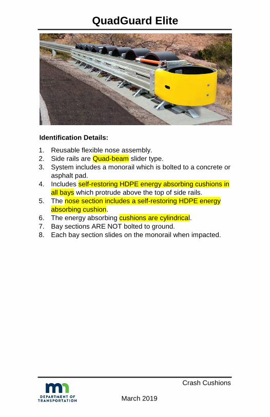
Identification Details:
1. Reusable flexible nose assembly.2. Side rails are Quad-beam slider type.3. System includes a monorail which is bolted to a concrete or
asphalt pad.4. Includes self-restoring HDPE energy absorbing cushions in
all bays which protrude above the top of side rails.5. The nose section includes a self-restoring HDPE energy
absorbing cushion.6. The energy absorbing cushions are cylindrical.7. Bay sections ARE NOT bolted to ground.8. Each bay section slides on the monorail when impacted.

HEART
Crash Cushions
March 2019
Identification Details:
1. Nose assembly is HDPE integral with the side panels.2. Side panels are self-restoring HDPE.3. System includes tubular steel track assembly serving as a
base which is bolted to a concrete pad.4. System includes steel diaphragms bolted to the side panels
at each bay section.5. System DOES NOT include any energy absorbing
cushions or cartridges.6. Each bay section slides on the tubular steel track assembly
when impacted.

REACT 350
Crash Cushions
March 2019
Identification Details: 1. System consists of 4, 6 or 9
HDPE cylindrical energyabsorbing cushions of varyingthickness.
2. System includes a self-contained or optional concretebackup.
3. System includes restrainingcable systems on each side ofthe cushions.
4. Restraining cable systems arerouted through a self-containedbackup (two cables-each side).
5. Restraining cable systems may be anchored to a concretebackup (four cables-each side).
6. System includes steel track assembly serving as a basewhich is bolted to a concrete pad.
7. System includes stabilizer chains which are bolted to thetrack assembly between the last four cushions.

X-MAS
Crash Cushions
March 2019
Identification Details:
1. Plastic nose assembly.2. Side rails are W-beam.3. Side rail adjacent to approach side traffic is straight.4. Side rail opposite approach side traffic is parabolic.5. Includes a strut assembly upstream of Post 1.6. Tensioning cables upstream of Post 1.7. Post 1 is steel hinged breakaway type.8. Post 2 through 6 may be wood breakaway or steel yielding:
a) Breakaway wood posts include a bored hole less than4” from finished grade.
b) Steel yielding posts include holes on the post flangesless than 4” from finished grade.

Universal TAU-II
Crash Cushions
March 2019
Identification Details:
1. Plastic nose assembly.2. Side rails are thrie beam
slider type.3. System is bolted to a
concrete or asphalt pad atthe leading and tail ends ofthe system ONLY.
4. Includes barrel-shapedenergy absorbingcartridges in all bays.
5. Cartridges protrude slightlyabove top of side rails.
6. System includes two cabletensioning assemblies.
7. Bay sections ARE NOT bolted to ground.8. Each bay section slides on sleds when impacted.

Universal TAU-II-R
Crash Cushions
March 2019
Identification Details:
1. Reusable flexible noseassembly.
2. Side rails are thrie beamslider type.
3. System is bolted to aconcrete or asphalt padat the leading and tailends of the systemONLY.
4. Includes four hyper-elastic polyurethane cushions in allbays.
5. Cushions are reusable.6. Cushions DO NOT protrude above top of side rails.7. System includes two cable tensioning assemblies.8. Bay sections ARE NOT bolted to ground.9. Each bay section slides on sleds when impacted.

Compressor
Crash Cushions
March 2019
Identification Details:
1. System does not have animpact nose assembly.
2. Side rails are thrie beam slidertype.
3. System includes a bolted sledassembly as a base.
4. Includes self-restoring HDPEenergy absorbing cushions inall bays of varying wallthickness.
5. Bay 3 to Bay 6 include HDPEenergy absorbing cushionswhich protrude above the topof side rail.
6. Each bay section slides along a center rail when impacted.