roadmap - iccsafe.org · ansi evsp standardization roadmap for electric vehicles, version 2.0 page...
TRANSCRIPT
ANSI EVSP Standardization Roadmap for Electric Vehicles, Version 2.0 Page 1 of 170
1
2
3
Standardization Roadmap for Electric Vehicles 4
5
Prepared by the 6
Electric Vehicles Standards Panel 7
of the 8
American National Standards Institute 9
10
11
12
13
14
Draft Version 2.0 15
Draft of April 30, 2013 16
17
18

ANSI EVSP Standardization Roadmap for Electric Vehicles, Version 2.0 Page 2 of 170
1
2
3
4
5
6
7
[this page intentionally left blank] 8
ANSI EVSP Standardization Roadmap for Electric Vehicles, Version 2.0 Page 3 of 170
Table of Contents 1
Table of Contents .................................................................................................................. 3 2
Acknowledgments ................................................................................................................. 7 3
Summary of Major Changes From Version 1.0 ...................................................................... 11 4
Executive Summary ............................................................................................................. 19 5
1. Introduction .................................................................................................................. 25 6
1.1 Situational Assessment for Electric Vehicles ........................................................................ 25 7
1.2 Roadmap Goals for EVs and Charging Infrastructure ........................................................... 27 8
1.3 Roadmap Boundaries .......................................................................................................... 28 9
1.4 Roadmap Audience ............................................................................................................. 29 10
1.5 Roadmap Structure ............................................................................................................. 29 11
1.6 Definitions .......................................................................................................................... 31 12
2. Background ................................................................................................................... 33 13
2.1 How the Roadmap was Developed and Promoted .............................................................. 33 14
2.2 Entities Operating in the EV Standards Space ...................................................................... 34 15
2.2.1 U.S.‐based SDOs ........................................................................................................................... 35 16
2.2.2 Non U.S.‐based SDOs ................................................................................................................... 36 17
2.2.3 U.S. Federal Government Agencies .............................................................................................. 37 18
2.2.4 World Forum for Harmonization of Vehicle Regulations (WP.29) ................................................. 38 19
2.2.5 Other Cross‐Sector Initiatives ....................................................................................................... 39 20
3. Identification of Issues ................................................................................................... 43 21
3.1 Vehicle Domain ................................................................................................................... 43 22
3.1.1 Energy Storage Systems ............................................................................................................... 44 23 3.1.1.1 Power Rating Methods ................................................................................................. 44 24 3.1.1.2 Battery Safety ............................................................................................................... 44 25 3.1.1.3 Battery Testing – Performance and Durability .............................................................. 44 26 3.1.1.4 Battery Storage, Packaging, Transport and Handling .................................................... 45 27 3.1.1.5 Battery Recycling .......................................................................................................... 45 28 3.1.1.6 Battery Secondary Uses ................................................................................................ 46 29 3.1.1.7 Crash Tests / Safety ...................................................................................................... 46 30
3.1.2 Vehicle Components .................................................................................................................... 47 31 3.1.2.1 Internal High Voltage Cables, On‐Board Wiring, Component Ratings and 32
Charging Accessories .................................................................................................... 47 33 3.1.2.2 Vehicle Diagnostics – Emissions .................................................................................... 47 34
Deleted: 3
Deleted: 7
Deleted: 11
Deleted: 19
Deleted: 25
Deleted: 25
Deleted: 27
Deleted: 28
Deleted: 29
Deleted: 29
Deleted: 31
Deleted: 33
Deleted: 33
Deleted: 34
Deleted: 35
Deleted: 36
Deleted: 37
Deleted: 38
Deleted: 39
Deleted: 43
Deleted: 43
Deleted: 44
Deleted: 44
Deleted: 44
Deleted: 44
Deleted: 45
Deleted: 45
Deleted: 46
Deleted: 46
Deleted: 47
Deleted: 47
Deleted: 47
ANSI EVSP Standardization Roadmap for Electric Vehicles, Version 2.0 Page 4 of 170
3.1.2.3 Audible Warning Systems ............................................................................................. 47 1
3.1.3 Vehicle User Interface .................................................................................................................. 47 2 3.1.3.1 Graphical Symbols ........................................................................................................ 48 3 3.1.3.2 Telematics – Driver Distraction ..................................................................................... 48 4 3.1.3.3 Fuel Efficiency, Emissions, and Labeling ........................................................................ 48 5
3.2 Infrastructure Domain ........................................................................................................ 48 6
3.2.1 Charging Systems ......................................................................................................................... 49 7 3.2.1.1 Wireless Charging ......................................................................................................... 49 8 3.2.1.2 Battery Swapping ......................................................................................................... 50 9 3.2.1.3 Electric Vehicle Supply Equipment (EVSE) ..................................................................... 50 10 3.2.1.4 Electromagnetic Compatibility (EMC) ........................................................................... 52 11 3.2.1.5 Vehicle as Supply .......................................................................................................... 52 12 3.2.1.6 Use of Alternative Power Sources ................................................................................. 53 13
3.2.2 Infrastructure Communications ................................................................................................... 53 14 3.2.2.1 Communications Architecture for EV Charging ............................................................. 54 15 3.2.2.2 Communications Requirements for Various EV Charging Scenarios .............................. 57 16 3.2.2.3 Communication and Measurement of EV Energy Consumption ................................... 58 17 3.2.2.4 Cyber Security and Data Privacy ................................................................................... 59 18 3.2.2.5 Telematics Smart Grid Communications ....................................................................... 59 19
3.2.3 Infrastructure Installation ............................................................................................................ 59 20 3.2.3.1 Site Assessment / Power Capacity Assessment ............................................................. 60 21 3.2.3.2 EV Charging – Signage and Parking ............................................................................... 60 22 3.2.3.3 Charging Station Permitting .......................................................................................... 60 23 3.2.3.4 Environmental and Use Conditions ............................................................................... 61 24 3.2.3.5 Ventilation – Multiple Charging Vehicles ...................................................................... 61 25 3.2.3.6 Guarding of EVSE .......................................................................................................... 61 26 3.2.3.7 Accessibility for Persons with Disabilities to EVSE ......................................................... 61 27 3.2.3.8 Cable Management ...................................................................................................... 62 28 3.2.3.9 EVSE Maintenance ........................................................................................................ 62 29 3.2.3.10 Workplace Safety ......................................................................................................... 62 30
3.3 Support Services Domain .................................................................................................... 62 31
3.3.1 Education and Training................................................................................................................. 64 32 3.3.1.1 Electric Vehicle Emergency Shut Off – High Voltage Batteries, Power Cables, 33
Disconnect Devices; Fire Suppression, Fire Fighting Tactics and Personal 34 Protective Equipment ................................................................................................... 65 35
3.3.1.2 Labeling of EVSE and Load Management Disconnects for Emergency Situations .......... 65 36 3.3.1.3 OEM Emergency Response Guides ............................................................................... 65 37 3.3.1.4 Electrical Energy Stranded in an Inoperable RESS; Battery Assessment and Safe 38
Discharge Following an Emergency Event ..................................................................... 66 39 3.3.1.5 Disaster Planning / Emergency Evacuations Involving Electric Vehicles ........................ 66 40 3.3.1.6 Workforce Training ....................................................................................................... 67 41
Deleted: 47
Deleted: 47
Deleted: 48
Deleted: 48
Deleted: 48
Deleted: 48
Deleted: 49
Deleted: 49
Deleted: 50
Deleted: 50
Deleted: 52
Deleted: 52
Deleted: 53
Deleted: 53
Deleted: 54
Deleted: 57
Deleted: 58
Deleted: 59
Deleted: 59
Deleted: 59
Deleted: 60
Deleted: 60
Deleted: 60
Deleted: 61
Deleted: 61
Deleted: 61
Deleted: 61
Deleted: 62
Deleted: 62
Deleted: 62
Deleted: 62
Deleted: 64
Deleted: 65
Deleted: 65
Deleted: 65
Deleted: 66
Deleted: 66
Deleted: 67
ANSI EVSP Standardization Roadmap for Electric Vehicles, Version 2.0 Page 5 of 170
4. Gap Analysis of Standards, Codes, Regulations, Conformance Programs and 1
Harmonization Efforts ......................................................................................................... 69 2
4.1 Vehicle Domain ................................................................................................................... 69 3
4.1.1 Energy Storage Systems ............................................................................................................... 70 4 4.1.1.1 Power Rating Methods ................................................................................................. 70 5 4.1.1.2 Battery Safety ............................................................................................................... 70 6 4.1.1.3 Battery Testing – Performance and Durability .............................................................. 74 7 4.1.1.4 Battery Storage, Packaging, Transport and Handling .................................................... 75 8 4.1.1.5 Battery Recycling .......................................................................................................... 78 9 4.1.1.6 Battery Secondary Uses ................................................................................................ 78 10 4.1.1.7 Crash Tests / Safety ...................................................................................................... 79 11
4.1.2 Vehicle Components .................................................................................................................... 80 12 4.1.2.1 Internal High Voltage Cables, On‐Board Wiring, Component Ratings and 13
Charging Accessories .................................................................................................... 80 14 4.1.2.2 Vehicle Diagnostics – Emissions .................................................................................... 83 15 4.1.2.3 Audible Warning Systems ............................................................................................. 84 16
4.1.3 Vehicle User Interface .................................................................................................................. 85 17 4.1.3.1 Graphical Symbols ........................................................................................................ 85 18 4.1.3.2 Telematics – Driver Distraction ..................................................................................... 86 19 4.1.3.3 Fuel Efficiency, Emissions and Labeling......................................................................... 86 20
4.2 Infrastructure Domain ........................................................................................................ 87 21
4.2.1 Charging Systems ......................................................................................................................... 87 22 4.2.1.1 Wireless Charging ......................................................................................................... 87 23 4.2.1.2 Battery Swapping ......................................................................................................... 88 24 4.2.1.3 Electric Vehicle Supply Equipment (EVSE) ..................................................................... 89 25 4.2.1.4 Electromagnetic Compatibility (EMC) ......................................................................... 100 26 4.2.1.5 Vehicle as Supply ........................................................................................................ 102 27 4.2.1.6 Use of Alternative Power Sources ............................................................................... 103 28
4.2.2 Infrastructure Communications ................................................................................................. 105 29 4.2.2.1 Communications Architecture for EV Charging ........................................................... 105 30 4.2.2.2 Communications Requirements for Various EV Charging Scenarios ............................ 108 31 4.2.2.3 Communication and Measurement of EV Energy Consumption ................................. 110 32 4.2.2.4 Cyber Security and Data Privacy ................................................................................. 114 33 4.2.2.5 Telematics Smart Grid Communications ..................................................................... 115 34
4.2.3 Infrastructure Installation .......................................................................................................... 115 35 4.2.3.1 Site Assessment / Power Capacity Assessment ........................................................... 115 36 4.2.3.2 EV Charging – Signage and Parking ............................................................................. 118 37 4.2.3.3 Charging Station Permitting ........................................................................................ 119 38 4.2.3.4 Environmental and Use Conditions ............................................................................. 120 39 4.2.3.5 Ventilation – Multiple Charging Vehicles .................................................................... 121 40 4.2.3.6 Guarding of EVSE ........................................................................................................ 122 41
Deleted: 69
Deleted: 69
Deleted: 70
Deleted: 70
Deleted: 70
Deleted: 74
Deleted: 75
Deleted: 78
Deleted: 78
Deleted: 79
Deleted: 80
Deleted: 80
Deleted: 83
Deleted: 84
Deleted: 85
Deleted: 85
Deleted: 86
Deleted: 86
Deleted: 87
Deleted: 87
Deleted: 87
Deleted: 88
Deleted: 89
Deleted: 100
Deleted: 102
Deleted: 103
Deleted: 105
Deleted: 105
Deleted: 108
Deleted: 110
Deleted: 114
Deleted: 115
Deleted: 115
Deleted: 115
Deleted: 118
Deleted: 119
Deleted: 120
Deleted: 121
Deleted: 122
ANSI EVSP Standardization Roadmap for Electric Vehicles, Version 2.0 Page 6 of 170
4.2.3.7 Accessibility for Persons with Disabilities to EVSE ....................................................... 123 1 4.2.3.8 Cable Management .................................................................................................... 124 2 4.2.3.9 EVSE Maintenance ...................................................................................................... 124 3 4.2.3.10 Workplace Safety Installation ..................................................................................... 125 4
4.3 Support Services Domain .................................................................................................. 125 5
4.3.1 Education and Training............................................................................................................... 125 6 4.3.1.1 Electric Vehicle Emergency Shut Off – High Voltage Batteries, Power Cables, 7
Disconnect Devices; Fire Suppression, Fire Fighting Tactics and Personal 8 Protective Equipment ................................................................................................. 125 9
4.3.1.2 Labeling of EVSE and Load Management Disconnects for Emergency Situations ........ 127 10 4.3.1.3 OEM Emergency Response Guides ............................................................................. 127 11 4.3.1.4 Electrical Energy Stranded in an Inoperable RESS; Battery Assessment and Safe 12
Discharge Following an Emergency Event ................................................................... 128 13 4.3.1.5 Disaster Planning / Emergency Evacuations Involving Electric Vehicles ...................... 129 14 4.3.1.6 Workforce Training ..................................................................................................... 129 15
5. Summary of Gap Analysis ............................................................................................. 135 16
6. On the Horizon ............................................................................................................ 149 17
Appendix A. EV Charging Actors and Communications ....................................................... 151 18
A.1 Introduction ...................................................................................................................... 151 19
A.2 Role of Communications in EV Charging Infrastructure ...................................................... 151 20
A.3 EV Charging Aspect of the Smart Grid ............................................................................... 152 21
A.4 Functional View of EV Charging Infrastructure Communications ....................................... 155 22
A.5 Communications Architecture for EV Charging .................................................................. 157 23
A.6 Actors ............................................................................................................................... 160 24
A.7 Sample Types of Communications Between Actors ........................................................... 161 25
Appendix B. Glossary of Acronyms and Abbreviations ........................................................ 165 26
27 28
Deleted: 123
Deleted: 124
Deleted: 124
Deleted: 125
Deleted: 125
Deleted: 125
Deleted: 125
Deleted: 127
Deleted: 127
Deleted: 128
Deleted: 129
Deleted: 129
Deleted: 135
Deleted: 149
Deleted: 151
Deleted: 151
Deleted: 151
Deleted: 152
Deleted: 155
Deleted: 157
Deleted: 160
Deleted: 161
Deleted: 165
ANSI EVSP Standardization Roadmap for Electric Vehicles, Version 2.0 Page 7 of 170
Acknowledgments 1
In addition to the individuals acknowledged in version 1.0 of this roadmap, thanks are extended to those 2
who commented on the roadmap or helped to promote it, and to the following professionals for their 3
contributions, financial and/or in‐kind support toward the development of this version 2.0 update. The 4
update is based on a consensus of the active participants and does not necessarily reflect the views of 5
the individuals or organizations listed. The employment status and affiliations of individual participants 6
are subject to change. 7
AEYCH LLC Hank McGlynn (SAE)
Alliance of Automobile Manufacturers Giedrius Ambrozaitis
American National Standards Institute Joe Bhatia, Susanah Doucet, Bei Gu, Rachel Howenstine, Gary Kushnier, Jim McCabe,*** Leslie McDermott, Liz Neiman, Elise Owen, Jessica Roop, Fran Schrotter
Amperex Technology Ltd. Bob Galyen (SAE)*, Joern Tinnemeyer (SAE)
Poul Andersen Consulting Poul Andersen
Argonne National Laboratory Theodore Bohn (DOE), Hina Chaudhry
Association of Global Automakers John Cabaniss, Julia Rege
ATIS Steve Barclay, Thomas Payne, Paul Savitz
Audi AG Martin Conrads
Autoliv Americas, ATC Doug Stein (SAE)
Automotive Manufacturing Technical Education Collaborative
Sam Collier
Better Place Liran Katzir, Frank Kitzantides,* Hugh McDermott, Ziva Patir
The Bishop Group Paul Bishop (IEEE)
CenterPoint Energy Greg Angst
Chrysler Rich Scholer (SAE)
Corning James E. Matthews, III**
Coulomb Technologies, Inc. Shantanu Kothavale,* Richard Lowenthal
CSA America Shawn Paulsen, Cliff Rondeau
Delphi David Lambert (Global Automakers), Laurie Moore
Duke Energy Michael D. Rowand, Mike Waters
Eaton Matt Guth, Kevin Lippert
EDF Energy R&D UK Centre Panagiotis Papadopoulos
Edison Electric Institute Steven Rosenstock
EFACEC Antonio Guimaraes
EIS Alliance Chris Kotting
Electric Power Research Institute Mark Duvall, John Halliwell
Elite Electronic Engineering Inc Craig Fanning
Energetics Fred Wagner (DOE)
EnerNex Dr. Aaron Snyder
Ericsson Stephen Hayes (ATIS)
Federal Energy Regulatory Commission Jessica Cockrell, Ray Palmer
ANSI EVSP Standardization Roadmap for Electric Vehicles, Version 2.0 Page 8 of 170
FirstEnergy Technologies Timothy Croushore
Ford John Bilezikjan (SAE)
General Electric Phil Piqueira, Heather Pugliese, Patrick Salas
General Motors George Bellino (SAE), Slav Berezin (SAE), Gery Kissel (SAE), David Reeck
Gridmerge Robert Cragie
Don Heirman Consultants Don Heirman
Hendry and Associates Anne Hendry
Honda Tommy Chang (Global Automakers)
Hubbell John Goodsell, Dennis Oddsen
IEEE Paul Bishop, Michael Kipness, Tim Kostyk, Russ Lefevre
International Assn of Electrical Inspectors David Clements
International Code Council Bruce E. Johnson, David Karmol, Kim Paarlberg, Kermit Robinson
Intertek Rich Byczek*
ITT Interconnect Solutions Lee Wolfel
Dale Kardos & Assoc. Inc. Dale Kardos* (Global Automakers)
LastMile TT Vishant Shah
Leviton Ken Brown (NEMA)
Magna E‐Car Zilai Zhao
Mitsubishi Electric Research Labs Zafer Sahinoglu
Mitsubishi Motors Corporation Bowu Reed
Mitsubishi Research Institute Yuichiro Shimura
Motorcycle Industry Council Pamela Arnette, Mel Stahl
National Electrical Contractors Assn Michael Johnston
National Electrical Manufacturers Assn Ryan Franks, Harry Massey, Andrei Moldoveanu, Paul Molitor*
National Fire Protection Association Kathleen Almand, Ryan Depew, Christian Dubay, Mark Earley,* Ken Willette*
National Highway Traffic Safety Administration Phil Gorney
National Institute of Standards & Technology Tanya Brewer, Marc Buttler, Dr. Allen Hefner, Dr. Jeffrey Mazer, Mary H. Saunders
National Renewable Energy Laboratory Mike Simpson (DOE)
Gregory C. Nieminski, LLC Greg Nieminski (EPRI)
Nissan USA Joe Thompson (Global Automakers)
Open Secure Energy Control Systems Stan Klein
P3 North America Arthur Holland (SAE)
Pacific Northwest National Laboratory Krishnan Gowri (DOE), Rick Pratt (DOE)
Panasonic Mike Stelts
PRBA – The Rechargeable Battery Association George Kerchner
Public Utilities Commission of Texas Julie Black
Qualcomm Mark Klerer
Rocky Mountain Institute Ben Holland
RSR Technologies, Inc. Dr. Tim Ellis, Dr. Jacob Hohn
ANSI EVSP Standardization Roadmap for Electric Vehicles, Version 2.0 Page 9 of 170
SAE International Peter Byk,* Patricia Ebejer, Jack Pokrzywa, Gary Pollak,* Gary Schkade, Keith Wilson*
San Diego Gas & Electric JC Martin
Schneider Electric Steve Hsu, Alan Manche,* James T. Pauley**
SEW‐Eurodrive Tim Schumann
Siemens Chun Fan, Rick Kluth, John Young
Sony Electronics, Inc. Dr. Paul J. Hearty
Southern California Edison Richard Hodson, Joshua McDonald,* Jose Salazar
ST Microelectronics James Allen (HomePlug Powerline Alliance, IEEE)
TDI Power John Santini
Telecommunications Industry Association Cheryl Blum, Herb Congdon
ThinkSmartGrid Mike Coop
TKstds Management Tom Kurihara (IEEE)
Tseng InfoServ, LLC Mitch Tseng
TUV SUD Canada Erik Spek (VdTÜV)
Underwriters Laboratories, Inc. Joseph Bablo,* Sonya Bird, Kenneth Boyce, Kent Donohue, Laurie Florence,* Maurice Johnson, John Thompson
U.S. Department of Energy Linda Bluestein, Keith Hardy, Lee Slezak
VdTÜV Volker Blandow, Sebastian Oertel
Xanthus Consulting International Frances Cleveland
*Asterisk following a name denotes Working Group Co‐Chair. 1
**Double asterisk following a name denotes ANSI EVSP Co‐Chair. 2
***Triple asterisk following a name denotes ANSI staff lead. 3
Parentheses signify participation on behalf of an organization. 4
5

ANSI EVSP Standardization Roadmap for Electric Vehicles, Version 2.0 Page 10 of 170
1
2
3
4
5
6
7
[this page intentionally left blank] 8
9
ANSI EVSP Standardization Roadmap for Electric Vehicles, Version 2.0 Page 11 of 170
Summary of Major Changes From Version 1.0 1
High‐Level Structural and Content Changes 2
The general structure of the roadmap version 1.0 has been retained. In addition to the inclusion of this 3
summary of major changes from version 1.0, other changes in structure and content are as follows: 4
- A new section 1.6 has been added to highlight definitions used in the document, specifically 5
electric vehicle supply equipment (EVSE). 6
- Section 2.1 was renamed How the Roadmap was Developed and Promoted to include summary 7
text about domestic and international coordination efforts. 8
- A new section 2.2.4 was added on the World Forum for the Harmonization of Vehicle 9
Regulations (WP.29). 10
- Other Cross‐Sector Initiatives was renumbered section 2.2.5. This section now includes an 11
expanded description of the work of the Smart Grid Interoperability Panel Vehicle to Grid 12
Domain Experts Working Group (SGIP V2G DEWG) and its roadmap, plus information about 13
regional and state initiatives. 14
- Sections 3.2.2 and 4.2.2 on Infrastructure Communications have been divided into parallel 15
subsections covering Communications Architecture for EV Charging; Communications 16
Requirements for Various EV Charging Scenarios; Communication and Measurement of EV 17
Energy Consumption; Cyber Security and Data Privacy; and, Telematics Smart Grid 18
Communications. It is clarified that standardization generally relating to smart device 19
communications, the connected vehicle, and intelligent transportation systems is out of scope; 20
rather, the focus is communications standardization that is essential or unique to the PEV 21
charging infrastructure (e.g., communications between an EV, EVSE and Energy Service 22
Provider). 23
- Subsections 3.2.3.2 and 4.2.3.2 have been renamed EV Charging – Signage and Parking. The text 24
includes discussions of public signage for EV charging and EV parking space allocation. 25
- Subsections 3.3.1.1 and 4.3.1.1 have been renamed Electric Vehicle Emergency Shut Off – High 26
Voltage Batteries, Power Cables, Disconnect Devices; Fire Suppression, Fire Fighting Tactics and 27
Personal Protective Equipment. The aspect regarding fire suppression, fire fighting tactics and 28
personal protective clothing is new. 29
- Subsections 3.3.1.2 and 4.3.1.2 have been renamed Labeling of EVSE and Load Management 30
Disconnects for Emergency Situations. 31
- Subsections 3.3.1.4 and 4.3.1.4 have been renamed Electrical Energy Stranded in an Inoperable 32
RESS; Battery Assessment and Safe Discharge Following an Emergency Event. The discussion of 33
stranded energy is new. 34
ANSI EVSP Standardization Roadmap for Electric Vehicles, Version 2.0 Page 12 of 170
- New subsections 3.3.1.5 and 4.3.1.5 have been added on Disaster Planning / Emergency 1
Evacuations Involving Electric Vehicles. Battery recharge in emergencies is addressed here. 2
- Workforce Training has been renumbered subsections 3.3.1.6 and 4.3.1.6. 3
- Section 4 gap statements now include an indication whether or not a gap is grid related and a 4
descriptor of the status of progress since the release of version 1.0 of the roadmap. Thus, the 5
status of progress is described as: Closed (completed) or, using a traffic light analogy, as Green 6
(moving forward), Yellow (delayed in progressing), Red (at a standstill), Not Started or Unknown. 7
New gaps for version 2.0 are identified as such. Any significant changes from version 1.0 are 8
summarized in an update statement. 9
- Section 5 has been renamed Summary of Gap Analysis and provides a table summarizing the 10
findings of the gap analysis in section 4 described above. On the far right of the table, a column 11
has been added on the Status of Progress since the release of version 1.0 of the roadmap. A key 12
at the top of the table defines the descriptors used to assess the status of progress. 13
- Section 6 has been renamed On the Horizon and briefly describes technology opportunities and 14
next steps. 15
- Appendix A has been substantially updated to provide a primer on EV communications. 16
Summary of Gap Analysis Changes 17
In roadmap version 2.0, a total of 58 issues are reviewed (versus 52 in version 1.0). Of these: 18
- 14 are issues where no gap was identified (versus 16 in version 1.0), meaning where it was felt 19
that existing standards and/or regulations adequately address the issue: 20
o 13 of these are carried over from version 1.0; 21
o 1 is a new issue, that being “Disaster Planning / Emergency Evacuations Involving 22
Electric Vehicles.” 23
- 44 gaps or partial gaps are identified (versus 36 in version 1.0); a “gap” is where no standard or 24
conformance program currently exists to address a safety, performance, or interoperability 25
issue). Of these: 26
- 30 of the gaps are near‐term priorities (versus 22 in version 1.0) which means they should 27
be addressed in 0‐2 years; 28
o 7 new gaps that are near‐term priorities are introduced in version 2.0. The status of 29
progress on all of them is green. 30
A new near‐term gap on “Electromagnetic Compatibility (EMC)” (4.2.1.4) 31
has been added with the recommendation to complete work on IEC 61851‐32
ANSI EVSP Standardization Roadmap for Electric Vehicles, Version 2.0 Page 13 of 170
21, Parts 1 and 2, and SAE J2954 to address EMC issues related to electric 1
vehicle charging. 2
A new near‐term gap on “Standardization of EV Sub‐meters” (4.2.2.3) has 3
been added with the recommendation to develop standards or guidelines 4
related to the functionality and measurement characteristics of the new 5
types of sub‐meters that are coming out for EVs, including embedded sub‐6
meters in the EVSE or EV. NEMA and the NIST U.S. National Working Group 7
on Measuring Systems for Electric Vehicle Fueling and Submetering 8
(USNWG EVF&S) are listed as potential developers. 9
A new near‐term gap on “Coordination of EV Sub‐metering activities” 10
(4.2.2.3) has been added with the recommendation that organizations 11
developing standards, guidelines or use cases related to EV sub‐metering 12
should coordinate their activities in order to avoid duplication of effort, 13
assure alignment, and maximize efficiency. Specifically, these are identified 14
as NEMA, the USNWG EVF&S, and the SGIP V2G DEWG. 15
A new near‐term gap on “Cyber Security and Data Privacy” (4.2.2.4) has 16
been added that there is a need for guidelines and standards to address 17
cyber security and data privacy concerns associated with PEVs and smart 18
grid communications. The recommendation is to complete work to develop 19
SAE J2931/7, and to revise ISO/IEC 15118‐1 and NISTR 7628, volume 2. 20
A new near‐term gap on “Telematics Smart Grid Communications” (4.2.2.5) 21
has been added that there is a need to develop use cases related to non‐22
utility aggregation control and vehicle information in order to assess the 23
existing functionalities, and to determine any missing requirements within 24
the context of existing standards, Energy Service Provider (ESP) business 25
requirements, and telematics networks to support smart grid load 26
management. The recommendation is to complete work on SAE J2836/5TM. 27
A new near‐term gap on “Electrical energy stranded in an Inoperable RESS” 28
(4.3.1.4) provides that standards to enable common method assessment of 29
rechargeable energy storage systems (RESS) condition and stability, and 30
removal of the energy stranded from an inoperable RESS, are needed to 31
increase the safety margin to persons who may become exposed to the 32
device in an inoperable state for various reasons and conditions during the 33
RESS life cycle. The recommendation is for NHTSA and the Argonne National 34
Laboratory to carry out a research project that they have begun to 35
independently identify a solution set to the issue of electrical energy 36
stranded in a damaged or inoperable RESS, and that work should be 37
completed on SAE J3009 to address a similar scope. 38
ANSI EVSP Standardization Roadmap for Electric Vehicles, Version 2.0 Page 14 of 170
A new near‐term gap on “Workforce Training – Charging Station Permitting” 1
(4.3.1.5) has been added to develop and promote a “Code Official Toolkit” 2
related to EVSE permitting. 3
o 4 of the gaps that were near‐term priorities identified in version 1.0 are now closed 4
or will be shortly: 5
The partial gap on “Power quality” (4.2.1.3) will be closed with the 6
publication of SAE J2894/2. 7
The partial gap on “EVSE charging levels” (4.2.1.3) with respect to DC 8
charging levels is now closed with the publication of the new version of 9
SAE J1772™. 10
The partial gap on “Off‐board charging station and portable EV cord set 11
safety within North America” (4.2.1.3) is closed with the publication of the 12
new tri‐national standard based on UL 2594. 13
The partial gap on “EV coupler safety within North America” (4.2.1.3) is 14
closed with the publication of the new tri‐national standard based on UL 15
2251. 16
o 19 of the gaps that are near‐term priorities are still open from version 1.0. The 17
status of progress can be described as follows: 14 are green, 2 are yellow, none are 18
red, 2 are not started, and 1 the status is unknown. Significant developments 19
include: 20
The gap on “Charging of roaming EVs between EVSPs” (4.2.2.2) notes that 21
NEMA’s EVSE section organized a working group to develop a standard that 22
supports roaming that allows charging services from a provider other than 23
the home EVSP. The standard will include inter‐operator interfaces to 24
address the various stages of a charging session (e.g., 25
authentication/authorization, charging data records, billing record 26
exchange.) The NEMA working group also is looking to develop a radio‐27
frequency identification (RFID) credential protocol specification so that all 28
EVSEs that implement the specification will be able to read RFID cards that 29
conform to the specification. IEC also has initiated work on IEC 62831 Ed. 30
1.0, User identification in Electric Vehicle Service Equipment using a 31
smartcard, which describes the physical and protocol layers of an RFID card 32
used in charging spots. 33
The gap on “Access control at charging stations” (4.2.2.2) indicates that 34
NEMA’s EVSE section set up a working group to look at this issue. It decided 35
ANSI EVSP Standardization Roadmap for Electric Vehicles, Version 2.0 Page 15 of 170
that offline access control lists were a low priority and deferred action on 1
offline access control to a later phase of work. 2
o 11 of the near‐term priorities from version 1.0 were substantially revised: 3
The recommendation on “Delayed battery overheating events” (4.1.1.2) was 4
revised to say that this issue should be addressed in future rulemaking 5
and/or revisions of SAE J2929 based on the results of the DOT/NHTSA‐6
funded SAE Cooperative Research Project. NHTSA has been added as a 7
potential developer. 8
The UN Subcommittee of Experts on the Transport of Dangerous Goods was 9
added as a potential developer to the gap on “Packaging and transport of 10
waste batteries” (4.1.1.4) as there is a proposal before it. 11
Regarding “Graphical symbols” (4.1.3.1), the text has been updated to note 12
NHTSA sponsored research on functional safety and failure modes. The 13
roadmap version 1.0 gap statement and recommendation have been re‐14
focused on communication of information to the driver. NHTSA has been 15
added as a potential developer and the priority level has been changed from 16
near‐term to long‐term. Regarding the roadmap version 1.0 gap statement 17
and recommendation relating to graphical symbols for “parts under the 18
hood,” this aspect is addressed in section 4.3.1.1 on EV emergency shut off. 19
The gap on “Wireless charging” (4.2.1.1) was modified to account for IEEE 20
and IEC/TC 69 work, with both added as potential developers. 21
The text and recommendation relating to “Battery swapping – safety” 22
(4.2.1.2) have been updated to note the new project IEC 62840 in IEC/TC 69. 23
The text on “EV coupler interoperability with EVSE globally” (4.2.1.3) has 24
been updated to note the publication of the SAE J1772TM AC/DC 25
combination coupler and that the forthcoming IEC 62196‐3 will describe the 26
SAE J1772™ coupler and several other different DC coupler configurations 27
used elsewhere. The gap statement notes the publication of SAE J1772TM. 28
The recommendation notes the need to incorporate SAE J1772TM into IEC 29
62196‐3 and the need to build out the charging infrastructure to 30
accommodate variations in coupler configurations for particular markets as 31
necessary, in particular with respect to DC charging. CHAdeMO, and “vehicle 32
and charging station manufacturers,” have been added alongside SAE and 33
IEC as “potential developers.” 34
The text, gap statement, recommendation and list of potential developers 35
on “Vehicle as supply” (4.2.1.5) have been substantially reworked to focus 36
ANSI EVSP Standardization Roadmap for Electric Vehicles, Version 2.0 Page 16 of 170
specifically on the need for harmonization of the DER communications 1
model between SAE J2836/3TM, IEC/TR 61850‐90‐8, and SEP 2.0. Potential 2
changes to other standards to address integration of inverter‐based DER 3
devices with the grid, or architecture and safety aspects of reverse power 4
flow, are contemplated in the text but not included as a gap. 5
The roadmap version 1.0 text, gap statement, recommendation and 6
potential developers on “Communication of standardized EV sub‐metering 7
data” (4.2.2.3) have been revised to be specific about communication of EV 8
sub‐metering data between third parties and service providers and to 9
complete work on the Green Button Sub‐metering Profile of ESPI. 10
The partial gap on “Electric Vehicle Emergency Shut Off” (4.3.1.1) largely has 11
been addressed with the publication of SAE J2990. The text, gap statement 12
and recommendation have been substantially modified to more broadly 13
capture the scope of safety concerns facing emergency responders including 14
the possibility that additional standardization work may be needed with 15
respect to fire suppression, fire fighting tactics and personal protective 16
equipment. 17
The text, gap statement and recommendation on “Labeling of EVSE and load 18
management disconnects” (4.3.1.2) have been clarified to address labeling 19
for emergency situations. UL and NEMA have been added as potential 20
developers. 21
The gap on “Battery assessment and safe discharge following an emergency 22
event” (4.3.1.4) has been modified to include an assessment of battery 23
stability. Emergency responders are no longer identified as the specific user 24
of battery discharge procedures since second responders (tow operators, 25
roadside assistance) and OEM representatives also may need such training. 26
The development of such procedures is now described as contingent upon 27
research underway by NHTSA / Argonne National Laboratory on stranded 28
energy. Argonne and NFPA have been added as potential developers. Text 29
regarding safe battery recharge in emergencies has been removed and a 30
new roadmap section on Disaster Planning / Emergency Evacuations 31
Involving Electric Vehicles has been added to separately address that 32
concern. 33
- 13 of the gaps are mid‐term priorities (versus 12 in version 1.0) which should be addressed 34
in 2‐5 years; 35
o 1 new mid‐term gap on “Workforce Training – Colleges and Universities” (4.3.1.5) 36
has been added to develop higher education programs focused on electric vehicle 37
ANSI EVSP Standardization Roadmap for Electric Vehicles, Version 2.0 Page 17 of 170
charging infrastructure development from the standpoint of land use, community 1
planning and architecture. 2
o Of the 12 mid‐term priorities from version 1.0 that are still open, the status of 3
progress can be described as follows: 4 are green, 2 are yellow, 1 is red, 4 are not 4
started, and 1 is unknown. Significant developments include: 5
Because of resource issues, work on the power rating method standards 6
(4.1.1.1) SAE J2907 and J2908 has been canceled and will be re‐opened 7
under a new J number at a future date yet to be determined. 8
The gap on “Locating and reserving a public charging station” (4.2.2.2) notes 9
that NEMA’s EVSE section organized a working group to develop a standard 10
that permits EV drivers to universally locate a public charging spot. It 11
decided that reserving a public charging spot was a low priority and 12
deferred action on reservations to a later phase of work. 13
In relation to the gap on “Accessibility for persons with disabilities to EVSE” 14
(4.2.3.7), additional text has been added to the roadmap describing the 15
two‐step process for addressing accessible EV parking and charging in 16
relevant standards and codes including the ICC A117.1, IBC®, IgCCTM, and 17
IZC®. Non‐accessible EV parking and charging also is addressed in the 18
roadmap text. 19
o 2 of the mid‐term priorities from version 1.0 have been substantially revised: 20
The gap on “Loss of control/dual mode failure in the battery” was reworked 21
as “Functional safety in the charging system” (4.1.1.2). The gap statement 22
and recommendation have been updated to note NHTSA‐funded research, 23
that the issue may be with the charging system rather than the battery, and 24
that NHTSA rulemaking may result. NHTSA has been added as a potential 25
developer and the priority level has been changed from mid‐term to near‐26
term. 27
The text and potential developers for “Guarding of EVSE” (4.2.3.6) have 28
been updated. NFPA has work on premises security and, so, has been added 29
as a potential developer. It does not appear that NHSTA has jurisdiction in 30
this area and neither it nor the American Association of State Highway and 31
Transportation Officials (AASHTO) have developed guidelines or standards 32
for guarding of EVSE. No other agencies or organizations have been 33
identified at this time that are working on this issue. 34
- 1 of the gaps is a long‐term priority (versus 2 in version 1.0) and should be addressed in 5+ 35
years. 36
ANSI EVSP Standardization Roadmap for Electric Vehicles, Version 2.0 Page 18 of 170
o As noted earlier, the gap on “Graphical Symbols” (4.1.3.1) is still open from version 1
1.0. The status is not started. 2
o 2 of the long‐term priorities from version 1.0 have been substantially revised: 3
The text and recommendation on “Battery recycling” (4.1.1.5) have been 4
updated to note relevant work by SAE. The priority level has been changed 5
from long‐term to near‐term. 6
The text on “Battery secondary uses” (4.1.1.6) has been updated to note 7
some of the considerations in the work thus far by the SAE committee. The 8
priority level of the gap has been changed from long‐term to mid‐term. 9
Additional Significant Text Changes 10
- Text regarding the work of the Electric Vehicle Safety Informal Working Group (EVS‐IWG) of 11
WP.29 has been added to Subsection 4.1.1.2 on Battery Safety. 12
- The work of the SAE EV Crash Test Safety Procedures Task Force has been noted in 13
Subsection 4.1.1.7 on Crash Tests / Safety. 14
- Text regarding the North American harmonization effort based on UL 2231, Parts 1 and 2, 15
has been added to Subsection 4.2.1.3 under EV Supply Equipment and Charging Systems. 16
- Additional information about the IEC 61851 series of standards, including on light electric 17
vehicles, and the IEC 62196 series, has been added to Subsection 4.2.1.3 on Electric Vehicle 18
Supply Equipment (EVSE). 19
- New Subsection 4.2.2.1 on Communications Architecture for EV Charging includes more 20
information on the relationship between the SAE communications standards and the 21
corresponding ISO/IEC 15118 series. 22
- New Subsection 4.2.2.2 on Communications Requirements for Various EV Charging 23
Scenarios includes text about European work related to communication between EVSEs and 24
charging network operating systems including the Open Charge Point Protocol (OCPP), eMI3 25
and Green eMotion, as well as inter‐operator interoperability, including the Open Clearing 26
House Protocol (OCHP) and Hubject joint venture. 27
- New Subsection 4.2.2.3 on Communication and Measurement of EV Energy Consumption 28
includes expanded text on sub‐metering, third party sub‐metering use cases, and 29
standardization activities including communications formats between a third party data 30
management agent and a billing agent and on functional and measurement characteristics 31
of third party sub‐meters. 32
- Additional text regarding challenges associated with the EVSE installation permitting process 33
is included in Subsection 4.2.3.3. 34
ANSI EVSP Standardization Roadmap for Electric Vehicles, Version 2.0 Page 19 of 170
Executive Summary 1
Electric vehicles (“EVs,” a/k/a electric drive vehicles) offer the potential to significantly reduce the 2
United States’ (U.S.) use of imported oil, create a multitude of well paying jobs through the 3
establishment of a broad, domestic EV industry, and reduce on‐road vehicular emissions. In order to 4
achieve this potential, and broadly penetrate the consumer market, EVs must be undeniably safe, 5
become more cost competitive, and otherwise satisfy user expectations and needs. 6
While there are many types of EVs, including those powered by fuel cells and other technologies, this 7
roadmap’s primary focus is on light duty, on‐road plug‐in electric vehicles (PEVs) that are recharged via a 8
connection to the electrical grid, as well as the supporting charging infrastructure needed to power 9
them. PEVs include battery‐powered all electric vehicles (AEVs), sometimes referred to as battery 10
electric vehicles (BEVs), and plug‐in hybrid electric vehicles (PHEVs). Some plug‐in models are also 11
extended range electric vehicles (EREVs) that function as an AEV, plus have a feature to extend vehicle 12
range beyond the battery (e.g., via a gasoline generator and other possibilities). Conventional hybrid EVs 13
(HEVs) which are recharged by an internal combustion engine are yet another type of EV and, while not 14
the focus of this roadmap, are noted where there are relevant safety and other considerations. 15
Given the current range limitations of plug‐in EVs on battery power alone, a critical need is the 16
establishment of a supporting charging infrastructure to enable vehicle recharging at home, at work, 17
and in public locations. This infrastructure must be reliable and broadly interoperable regardless of the 18
type of PEV or charging system utilized. 19
Equally important is the establishment of a comprehensive and robust support services sector that 20
includes training of emergency first responders, vehicle technicians, electrical installers and inspectors, 21
as well as education of authorities having jurisdiction, building owners, and consumers. 22
Never has there been a more auspicious time for EVs than the present. Nonetheless, while the times 23
appear especially promising, EVs do face significant challenges to widespread adoption. In order for EVs 24
to be broadly successful, the following challenges must be successfully addressed: 25
Safety: While inherently neither more nor less safe than conventional internal combustion engine 26
vehicles, EVs do have unique safety complexities and risks which must be understood and accounted for 27
as part of the vehicle life cycle. 28
Affordability: Cost is a critical issue which must be continually addressed in order for EVs to become 29
widely accepted and broadly penetrate the consumer market. 30
Interoperability: The ability to recharge anywhere in a secure fashion will greatly enhance EV driver 31
flexibility and user convenience. 32
Performance: The ability to extend the driving range of EVs on a single battery charge without the need 33
for range extension is largely due to energy storage capabilities (batteries) and a function of technology 34
development. 35
ANSI EVSP Standardization Roadmap for Electric Vehicles, Version 2.0 Page 20 of 170
Environmental Impact: The demand from both regulators and consumers for “greener” vehicles 1
(i.e., more fuel‐efficient, less reliant on fossil fuels) must be met. 2
Standards, code provisions, and regulations, as well as conformance and training programs, cross over 3
all these areas and are a critical enabler of the large‐scale introduction of EVs and the permanent 4
establishment of a broad, domestic EV and infrastructure industry and support services environment. 5
Roadmap Goals, Boundaries and Audience: In order to assess the standards and conformance programs 6
needed to facilitate the safe, mass deployment of EVs and charging infrastructure in the United States, 7
the American National Standards Institute (ANSI) convened the Electric Vehicles Standards Panel (ANSI 8
EVSP or “the Panel”). The decision to form the Panel was made at a meeting of key stakeholders in 9
March 2011 which ANSI convened in response to suggestions that the U.S. standardization community 10
needed a more coordinated approach to keep pace with electric vehicle initiatives moving forward in 11
other parts of the world. This effort draws upon participants from the automotive, utilities, and 12
electrotechnical sectors as well as from standards developing organizations (SDOs or “developers”) and 13
government agencies. 14
In April 2012, the ANSI EVSP released the Standardization Roadmap for Electric Vehicles – Version 1.0 15
(“roadmap”). The goals of this update to the roadmap remain the same, namely to: 16
1. Facilitate the development of a comprehensive, robust, and streamlined standards and 17
conformance landscape; and 18
2. Maximize the coordination and harmonization of the standards and conformance 19
environment domestically and with international partners. 20
Accordingly, the focus of this roadmap is to comprehensively identify, inventory, and assess existing 21
standards, relevant codes and regulations, and related conformance and training programs, ascertain 22
gaps and recommended solutions. This includes identification of prioritized timeframes for when 23
standardization should occur and SDOs that may be able to lead the work. 24
It is important to emphasize that the focus of this roadmap is not merely to identify gaps and then to 25
suggest development of new standards or conformance programs to fill them. Rather, it is also to 26
identify opportunities where gaps potentially can be filled by revising or harmonizing existing standards 27
and conformance programs. 28
Several high level boundaries have been established in the development of this roadmap. The focus is 29
on PEVs, charging systems, and associated support services. Standards and conformance activities are 30
emphasized that have direct applicability to the U.S. market for PEVs and charging infrastructure. 31
Additionally, this roadmap has been developed with an eye toward international activities and 32
harmonization, and a strong emphasis is placed upon establishing priorities for near‐term 33
standardization needs (0‐2 years), while also assessing mid‐term (2‐5 years), and long‐term (5+ years) 34
requirements. 35
ANSI EVSP Standardization Roadmap for Electric Vehicles, Version 2.0 Page 21 of 170
This roadmap is targeted toward a broad audience including SDOs; U.S. federal, state, and municipal 1
governments; and the automotive, electrotechnical, and utilities industries, among others. 2
Entities Operating in the EV Space: The U.S. standards system acknowledges that there are multiple 3
paths to achieving globally relevant standards. Many SDOs and consortia operate on an international 4
scale and what matters is that the standards are developed according to the principles of the World 5
Trade Organization’s Technical Barriers to Trade Agreement. Coordination and harmonization among 6
international standardizing bodies is an aspirational goal that will help to foster innovation and grow 7
global markets for EVs. Suffice it to say that the deployment of EVs in the United States will be shaped 8
by the standards activities of a number of SDOs, both U.S.‐based and non‐U.S. based, as well as codes, 9
regulations, conformance and training programs, and related activities of many stakeholders, including 10
U.S. federal government agencies, inter‐governmental bodies, and other cross‐sector initiatives. 11
Roadmap Structure: The broad electric vehicle and infrastructure system is very complex and dynamic, 12
undergoing continual evolution and adaption, with many parties involved. In order to develop this 13
roadmap, it was necessary to frame activities under three broad domains: vehicles, infrastructure, and 14
support services. Within those three domains, seven broad topical areas of relevance to standards and 15
conformance programs for electric vehicles were identified: energy storage systems, vehicle 16
components, and vehicle user interface within the vehicle domain; charging systems, communications 17
and installation within the infrastructure domain; and education and training within the support services 18
domain. 19
While some distinct issues within the topical areas are solely applicable to one specific domain, in 20
general they are highly interrelated and interdependent. In many, if not most cases, important issues 21
related to standards and conformance programs cross over at least two of the domains simultaneously, 22
if not all three. Understanding the interrelationships and interfaces between the domains, topical areas, 23
and issues is essential. 24
Section 2 of the roadmap provides additional background regarding how this roadmap was developed 25
and promoted, and some of the key players that are shaping the standardization landscape for PEVs and 26
charging infrastructure. 27
Section 3 of the roadmap provides the context and explanation for why specific issues were considered 28
important and subsequently assessed as part of this roadmap. Sections 3 and 4 parallel one another in 29
structure to facilitate ease of use, cross comparisons, and consideration of issues across domains and 30
topical areas. 31
Section 4 is the gap analysis of standards, codes, regulations, conformance programs, and 32
harmonization efforts. This evaluation looks at existing and needed standards and conformance 33
programs that are relevant to the rollout of electric vehicles and charging infrastructure in the United 34
States. Where gaps are identified, recommendations for remediation are noted. Based on an 35
assessment of the acuteness of risk, a priority for addressing each gap is noted, along with an indication 36
of the potential developer(s) who could undertake the work. Gap statements also include an indication 37
ANSI EVSP Standardization Roadmap for Electric Vehicles, Version 2.0 Page 22 of 170
whether or not a gap is grid related and a descriptor of the status of progress since the roadmap version 1
1.0 was released. 2
Section 5 provides a table summarizing the findings of the gap analysis in section 4. 3
Section 6 briefly describes what is on the horizon in terms of technology opportunities and next steps. 4
Additionally, this roadmap is supplemented by the ANSI EVSP Roadmap Standards Compendium 5
(“compendium”), a searchable spreadsheet which inventories standards that are directly or peripherally 6
related to each issue, while also identifying related issues to which the standards potentially apply. Like 7
the roadmap itself, the compendium has been updated since its original publication in April 2012. 8
Summary of Gaps and Recommendations: Presently, this roadmap has identified a total of 44 gaps or 9
partial gaps and corresponding recommendations across the three domains and seven topical areas. 10
Thirty of these gaps / recommendations have been identified as near‐term priorities, thirteen as mid‐11
term priorities, and one as a long‐term priority. 12
Specifically, with regards to near‐term safety and other priorities, the following gaps/partial gaps have 13
been identified: functional safety in the charging system; delayed battery overheating events; safe 14
storage of lithium‐ion batteries; packaging and transport of waste batteries; battery recycling; audible 15
warning systems; wireless charging; battery swapping (both safety and interoperability); power quality; 16
EVSE charging levels; off‐board charging station and portable EV cord set safety within North America; 17
EV coupler safety within North America; EV coupler interoperability with EVSE globally; conformance 18
programs for EV coupler interoperability within the U.S. market; electromagnetic compatibility (EMC); 19
vehicle as supply / reverse power flow; use of alternative power sources; charging of roaming EVs 20
between EVSPs; access control at charging stations; communication of standardized EV sub‐metering 21
data; standardization of EV sub‐meters; coordination of EV sub‐metering activities; cyber security and 22
data privacy; telematics smart grid communications; electric vehicle emergency shutoff – high voltage 23
batteries, power cables, disconnect devices; fire suppression, fire fighting tactics and personal protective 24
equipment; labeling of EVSE and load management disconnects for emergency situations; electrical 25
energy stranded in an inoperable RESS; battery assessment and safe discharge following an emergency 26
event; and, workforce training – charging station permitting. 27
In this context, a gap refers to a significant issue – whether it be related to safety, performance, 28
interoperability, etc. – that has been identified and that should be addressed in a standard, code, 29
regulation, or conformance program but for which currently none is published or known to exist that 30
adequately addresses the issue. Gaps can be filled through the creation of entirely new standards, code 31
provisions, regulations, or conformance programs, or through revisions to existing ones. In some cases 32
work may already be in progress to fill the gap. 33
A partial gap refers to a situation where a significant issue has been identified that is partially addressed 34
by an existing standard, code, regulation, or conformance program. No gap means there is no significant 35
issue that has been identified at this time or that is not already adequately covered by an existing 36
standard, code, regulation, or conformance program. 37
ANSI EVSP Standardization Roadmap for Electric Vehicles, Version 2.0 Page 23 of 170
Next Steps: While this roadmap represents a specific snapshot in time, it maintains a distinctively 1
outward looking, over the horizon posture that will continue to facilitate discussions with domestic, 2
regional and international partners regarding coordination and harmonization of standardization 3
activities and adaption to technological and policy changes. 4
Depending upon the needs of stakeholders, and available resources, periodic updates on significant 5
electric vehicle standardization activities and progress to address the gaps identified in this roadmap will 6
be made. Issues that are new or that require further discussion also may be explored. The aim behind 7
any such efforts will be to continue to help guide, coordinate, and enhance the standards landscape as 8
needed to support the widespread introduction of PEVs and charging infrastructure. 9
10

ANSI EVSP Standardization Roadmap for Electric Vehicles, Version 2.0 Page 24 of 170
1
2
3
4
5
6
7
[this page intentionally left blank] 8
ANSI EVSP Standardization Roadmap for Electric Vehicles, Version 2.0 Page 25 of 170
1. Introduction 1
Electric vehicles (“EVs,” a/k/a electric drive vehicles) offer the potential to significantly reduce the 2
United States’ (U.S.) use of imported oil, create a multitude of well paying jobs through the 3
establishment of a broad, domestic EV industry, and reduce on‐road vehicular emissions. In order to 4
achieve this potential, and broadly penetrate the consumer market, EVs must be undeniably safe, 5
become more cost competitive, and otherwise satisfy user expectations and needs. 6
While there are many types of EVs, including those powered by fuel cells and other technologies, this 7
roadmap’s primary focus is on light duty, on‐road plug‐in electric vehicles (PEVs) that are recharged via a 8
connection to the electrical grid, as well as the supporting charging infrastructure needed to power 9
them. PEVs include battery‐powered all electric vehicles (AEVs), sometimes referred to as battery 10
electric vehicles (BEVs), and plug‐in hybrid electric vehicles (PHEVs). Some plug‐in models are also 11
extended range electric vehicles (EREVs) that function as an AEV, plus have a feature to extend vehicle 12
range beyond the battery (e.g., via a gasoline generator and other possibilities). Conventional hybrid EVs 13
(HEVs) which are recharged by an internal combustion engine are yet another type of EV and, while not 14
the focus of this roadmap, are noted where there are relevant safety and other considerations. 15
Given the current range limitations of plug‐in EVs on battery power alone, a critical need is the 16
establishment of a supporting charging infrastructure to enable vehicle recharging at home, at work, 17
and in public locations. This infrastructure must be reliable and broadly interoperable regardless of the 18
type of EV or charging system utilized. 19
Equally important is the establishment of a comprehensive and robust support services sector that 20
includes training of emergency first responders, vehicle technicians, electrical installers and inspectors, 21
as well as education of authorities having jurisdiction, building owners, and consumers. 22
Standards, code provisions, and regulations, as well as conformance and training programs, cross over 23
all these areas and are a critical enabler of the large‐scale introduction of EVs and the permanent 24
establishment of a broad, domestic EV and infrastructure industry and support services environment. 25
1.1 Situational Assessment for Electric Vehicles 26
Several factors are driving the keen interest in EVs. Certainly, U.S. government concerns over energy 27
security and dependency on imported petroleum from increasingly unstable foreign markets is a 28
primary driver. The potential of EVs to offer a solution to this problem, to contribute to the reduction of 29
greenhouse gas emissions, and to promote economic growth and jobs creation in the new technologies, 30
has spurred substantial government investment in electric vehicle research and infrastructure. In his 31
2011 State of the Union address, U.S. President Barack Obama announced the goal of putting one 32
million electric vehicles on U.S. highways by 2015. There is also increasing demand for low‐emission, 33
fuel‐efficient and affordable vehicles from consumers who want to demonstrate their commitment to 34
the environment. 35
ANSI EVSP Standardization Roadmap for Electric Vehicles, Version 2.0 Page 26 of 170
Never has there been a more auspicious time for EVs than the present. In recent years, there have been 1
major advances in energy storage technologies (most especially lithium‐ion based technologies) that 2
have led to significant improvements in energy‐ and power density along with reduced costs. There have 3
also been steady achievements with regards to hybrid power train developments, power electronics, 4
and electric machines. Corporate average fuel economy (CAFÉ) requirements for 2016 and beyond 5
provide an additional impetus behind EVs. And never before has there been such a broad interest and 6
commitment by the automobile industry to the success of EVs. 7
Nonetheless, while the times appear especially promising, EVs do face significant challenges to 8
widespread adoption. In order for EVs to be broadly successful, the following challenges must be 9
successfully addressed: safety, affordability, interoperability, performance, and environmental impact. 10
These also can be viewed as core values that will directly impact consumer acceptance of EVs. 11
Standards, codes, regulations, and related conformance and training programs, are essential 12
components that will aid in successfully addressing these concerns. 13
Safety: While inherently neither more nor less safe than conventional internal combustion engine 14
vehicles, EVs do have unique safety complexities and risks which must be understood and accounted for 15
as part of the vehicle life cycle. Given the high voltages and currents in EVs, battery and cable safety is 16
especially important. This is true not only in accident situations for occupants and rescue personnel, but 17
during charging, vehicle/battery repair, replacement, and recycling. Standards play an invaluable role in 18
ensuring the safety of EV systems (and risks to technology manufacturers) especially if standards lead or 19
at a minimum keep pace with and foreshadow technology evolution. Forward‐leaning safety standards, 20
codes, and regulations, complemented by conformance programs and training, are in fact essential to 21
avoiding accidents and public safety risks that potentially could adversely affect the widespread viability 22
of EVs. 23
Affordability: Cost is a critical issue which must be continually addressed in order for EVs to become 24
widely accepted and broadly penetrate the consumer market. EVs are more expensive than 25
conventional vehicles, largely driven by battery capital and replacement costs which are related to 26
economies of scale, manufacturing technology, and raw materials. Likewise, the cost of infrastructure 27
technology and installation needs to be reduced to bring the overall EV system life cycle cost in line with 28
that of conventional vehicles. 29
While standards, codes, and regulations do not directly impact the cost of EV systems, they do so 30
indirectly. For example, comprehensive, clear, and forwardly insightful standards and codes reduce risk 31
and uncertainty for technology developers and investors, serving as an insurance policy of sorts. A well 32
designed and fully developed standard and code environment encourages competition through 33
facilitation of new market entrants and increased private sector investment. Standards for recharging 34
will also lower costs for manufacturers and consumers. 35
Interoperability: The ability to recharge anywhere in a secure fashion will greatly enhance EV driver 36
flexibility and user convenience. Well established interoperability standards and communications 37
systems which facilitate the ability to remotely locate, price compare, and reserve charging sites along 38
ANSI EVSP Standardization Roadmap for Electric Vehicles, Version 2.0 Page 27 of 170
travel routes will be invaluable, especially in the early years of EV deployment given the relative scarcity 1
of charging infrastructure. Billing under different charging scenarios must be seamless and efficient. 2
It will be important for standards to be designed to facilitate upgrade paths and flexible compatibility 3
with quickly evolving communications and smart grid technologies. A bit further out possibly, but also 4
important, are standards to facilitate vehicle energy to home and grid applications. Significantly greater 5
interoperability will lead to manufacturing efficiencies for both the vehicle and built infrastructure 6
leading to greater affordability and reduced financial risk. 7
Performance: The ability to extend the driving range of PEVs on a single battery charge without the 8
need for range extension is largely due to energy storage capabilities (batteries) and a function of 9
technology development. As standards, codes, and regulations help to reduce overall risk, it is likely that 10
more technology firms will enter the market and investment will increase, thereby leading to a 11
quickened pace of technology advancement. Standards for fast charging will help to define this market, 12
accelerate development of more cost effective fast charging systems, enhance user convenience, and 13
extend EV driving range. These factors will enhance business and consumer confidence in, and electric 14
driving performance of, PEVs, making them increasingly attractive as a practical and reliable alternative 15
to conventional vehicles. 16
Environmental Impact: The demand from both regulators and consumers for “greener” vehicles (i.e., 17
more fuel‐efficient, less reliant on fossil fuels) must be met. This will continue to drive technological 18
developments and standardization efforts within the auto industry. This includes batteries with 19
enhanced storage capacity as well as investigation of renewables as alternative power sources. The 20
ability to safely and efficiently recharge EVs in residential, commercial and public settings without 21
adverse grid impacts is essential, and also the subject of standardization activity and technological 22
advancements. 23
1.2 Roadmap Goals for EVs and Charging Infrastructure 24
In order to assess the standards and conformance programs needed to facilitate the safe, mass 25
deployment of EVs and charging infrastructure in the United States, the American National Standards 26
Institute (ANSI)1 convened the Electric Vehicles Standards Panel (ANSI EVSP or “the Panel”). In April 27
1 ANSI is a non‐profit organization that coordinates the U.S. private sector standards and conformance system – a
system that relies upon close collaboration and partnership between the public and private sectors. ANSI
represents thousands of member companies, organizations, and individuals who rely upon standards and
conformance to increase efficiency, create market acceptance, improve competitiveness, and foster international
commerce. For more than ninety years, ANSI and its members have worked to demonstrate the strength of private
sector‐led and public sector‐supported, market‐driven, standards‐based solutions that are characterized by
consensus, openness, and balance. ANSI is the U.S. member of the International Organization for Standardization
(ISO) and, via the U.S. National Committee, the International Electrotechnical Commission (IEC).
ANSI EVSP Standardization Roadmap for Electric Vehicles, Version 2.0 Page 28 of 170
2012, the ANSI EVSP released the Standardization Roadmap for Electric Vehicles – Version 1.0 1
(“roadmap”).2 The goals of this update to the roadmap remain the same, namely to: 2
1. Facilitate the development of a comprehensive, robust, and streamlined standards and 3
conformance landscape; and 4
2. Maximize the coordination and harmonization of the standards and conformance environment 5
domestically and with international partners. 6
Accordingly, the focus of this roadmap is to comprehensively identify, inventory, and assess existing 7
standards, relevant codes and regulations, and related conformance and training programs, ascertain 8
gaps and recommend solutions. This includes identification of prioritized timeframes and potential 9
standards developing organizations (SDOs or “developers”) that may be able to lead the work. This 10
roadmap also aspires to discuss coordination of SDOs and oversight bodies (domestic and international), 11
as well as provide a framework to monitor the evolving technical and policy landscape for EVs and 12
infrastructure with regards to standards and conformance programs. 13
It is important to emphasize that the focus of this roadmap is not merely to identify gaps and then to 14
suggest development of new standards or conformance programs to fill them. Rather, it is also to 15
identify opportunities where gaps potentially can be filled by revising or harmonizing existing standards 16
and conformance programs. 17
1.3 Roadmap Boundaries 18
In order to manage scope, emphasize priorities, and adhere to a compressed timetable, several high 19
level boundaries have been established in the development of this roadmap: 20
- The emphasis is on standards and conformance programs that are specific to on‐road plug‐in 21
EVs (PEVs) consisting of battery‐powered all electric vehicles (AEVs) and plug‐in hybrid EVs 22
(PHEVs), charging infrastructure, and associated support services, as opposed to other types of 23
EVs or more general road vehicle and electrical infrastructure standardization activity. 24
- Standards and conformance programs that address the key challenges and core consumer 25
values of safety, affordability, interoperability, performance, and environmental impact are 26
targeted. 27
- Standards and conformance activities that have direct applicability to the U.S. market for PEVs 28
and charging infrastructure are the primary focus. 29
2 http://publicaa.ansi.org/sites/apdl/evsp/ANSI_EVSP_Roadmap_April_2012.pdf
ANSI EVSP Standardization Roadmap for Electric Vehicles, Version 2.0 Page 29 of 170
- This roadmap has been developed with an eye toward international activities and 1
harmonization, especially with regards to Canada and the European Union (EU). Harmonization 2
refers to efforts to align or make equivalent the requirements in standards and conformance 3
programs. 4
- As a result of the acute need for standards and conformance programs to pace the rapidly 5
evolving EV environment, a strong emphasis is placed upon establishing priorities for near‐term 6
standardization needs (0‐2 years), while also assessing mid‐term (2‐5 years) and long‐term (5+ 7
years) requirements. 8
1.4 Roadmap Audience 9
This roadmap is targeted toward a broad audience including standards development organizations 10
(SDOs); U.S. federal, state, and municipal governments; and the automotive, electrotechnical, and 11
utilities industries, among others. 12
This roadmap may assist SDOs in identifying priority areas, establishing boundaries, and identifying 13
opportunities for collaboration, consolidation, and harmonization. In addition, as specific gaps are 14
identified for the overall EV standards landscape, it will be easier for SDOs to prioritize their activities 15
over the near‐term, mid‐term, and long‐term timeframes. 16
This roadmap will assist federal and state government entities in establishing a coherent and 17
coordinated U.S. EV policy, and participating in or tracking the progress of associated technical activities. 18
It will also assist harmonization efforts with regional and international entities on needed standards and 19
conformance programs. 20
This roadmap will serve municipal governments and other like entities in understanding the issues and 21
complexities surrounding EVs, infrastructure, and supporting services, and where to find resolution 22
when looking to establish EV deployment strategies in local communities. 23
This roadmap will help industry to target standards participation efforts, and aid in the development of 24
EV technologies and related conformance programs. It will also enable industry to identify commercial 25
opportunities, to gain insights to support business strategies and technology sequencing, and to reduce 26
safety and economic risks. 27
1.5 Roadmap Structure 28
The broad electric vehicle and infrastructure system is very complex and dynamic, undergoing continual 29
evolution and adaptation, with many parties involved. In order to develop this roadmap, it was 30
necessary to frame activities under three broad domains: Vehicles, Infrastructure, and Support Services. 31
Within those three domains, seven broad topical areas of relevance to standards and conformance 32
programs for electric vehicles were identified: Energy Storage Systems, Vehicle Components, and 33
Vehicle User Interface within the Vehicle Domain; Charging Systems, Communications and Installation 34
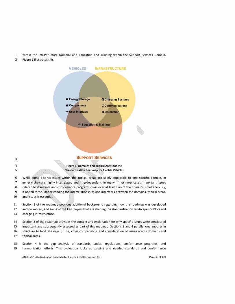
ANSI EVSP Standardization Roadmap for Electric Vehicles, Version 2.0 Page 30 of 170
within the Infrastructure Domain; and Education and Training within the Support Services Domain. 1
Figure 1 illustrates this. 2
3
Figure 1: Domains and Topical Areas for the 4 Standardization Roadmap for Electric Vehicles 5
While some distinct issues within the topical areas are solely applicable to one specific domain, in 6
general they are highly interrelated and interdependent. In many, if not most cases, important issues 7
related to standards and conformance programs cross over at least two of the domains simultaneously, 8
if not all three. Understanding the interrelationships and interfaces between the domains, topical areas, 9
and issues is essential. 10
Section 2 of the roadmap provides additional background regarding how this roadmap was developed 11
and promoted, and some of the key players that are shaping the standardization landscape for PEVs and 12
charging infrastructure. 13
Section 3 of the roadmap provides the context and explanation for why specific issues were considered 14
important and subsequently assessed as part of this roadmap. Sections 3 and 4 parallel one another in 15
structure to facilitate ease of use, cross comparisons, and consideration of issues across domains and 16
topical areas. 17
Section 4 is the gap analysis of standards, codes, regulations, conformance programs, and 18
harmonization efforts. This evaluation looks at existing and needed standards and conformance 19
ANSI EVSP Standardization Roadmap for Electric Vehicles, Version 2.0 Page 31 of 170
programs that are relevant to the rollout of electric vehicles and charging infrastructure in the United 1
States. Where gaps are identified, recommendations for remediation are noted. Based on an 2
assessment of the acuteness of risk, a priority for addressing each gap is noted, along with an indication 3
of a potential developer(s) who could undertake the work. 4
In this roadmap update, section 4 gap statements now include an indication whether or not a gap is grid 5
related and a descriptor of the status of progress since the release of version 1.0 of the roadmap. Thus, 6
the status of progress is described as: Closed (completed) or, using a traffic light analogy, as Green 7
(moving forward), Yellow (delayed in progressing), Red (at a standstill), Not Started or Unknown. New 8
gaps for version 2.0 are identified as such. Any significant changes from version 1.0 are summarized in 9
an update statement. 10
Section 5, the Summary of Gap Analysis, provides a table summarizing the findings of the gap analysis in 11
section 4 described above. On the far right of the table, a column has been added on the Status of 12
Progress since the release of version 1.0 of the roadmap. A key at the top of the table defines the 13
descriptors used to assess the status of progress. 14
Section 6 briefly describes what is on the horizon in terms of technology opportunities and next steps. 15
This roadmap is supplemented by the ANSI EVSP Roadmap Standards Compendium, a searchable 16
spreadsheet which inventories standards that are directly or peripherally related to each issue, while 17
also identifying related issues to which the standards potentially apply.3 Like the roadmap itself, the 18
compendium has been updated since its initial publication in April 2012. 19
1.6 Definitions 20
For purposes of defining the scope of this roadmap, the ANSI EVSP agreed to apply the definition of 21
electric vehicle found in the 2011 and 2014 versions of NFPA 70®, the National Electrical Code® (NEC®), 22
given below, with the primary focus being on‐road vehicles containing a battery that is recharged via the 23
electrical grid, and related infrastructure. 24
Electric Vehicle. An automotive‐type vehicle for on‐road use, such as passenger automobiles, 25
buses, trucks, vans, neighborhood electric vehicles, electric motorcycles, and the like, primarily 26
powered by an electric motor that draws current from a rechargeable storage battery, fuel cell, 27
photovoltaic array, or other source of electric current. Plug‐in hybrid electric vehicles (PHEV) are 28
considered electric vehicles. For the purpose of this article, off‐road, self‐propelled electric 29
vehicles, such as industrial trucks, hoists, lifts, transports, golf carts, airline ground support 30
equipment, tractors, boats, and the like, are not included. 31
3 The ANSI EVSP Roadmap Standards Compendium can be found at www.ansi.org/evsp.
ANSI EVSP Standardization Roadmap for Electric Vehicles, Version 2.0 Page 32 of 170
In addition to what is not included in the NFPA 70® definition, the Panel further agreed to not include 1
aircraft, or vehicles on fixed guideways (e.g., rails, monorails) such as trains or trolleys. While not 2
relevant to the infrastructure discussion applicable to PEVs and PHEVs, the panel agreed to consider in 3
part hybrid electric vehicles (HEVs) that are recharged by internal combustion engines to the extent that 4
they pose safety concerns, e.g., for emergency responders. 5
As used throughout this roadmap, the term electric vehicle supply equipment (EVSE) encompasses both 6
of the following definitions that will be found in article 625 of the NEC® 2014 version: 7
Electric Vehicle Charging System. A system of components that provide a dc output that is 8
supplied to the vehicle for the purpose of recharging electric vehicle storage batteries; and 9
Electric Vehicle Supply Equipment System. A system of components that provide an ac output 10
that is supplied to the vehicle for the purpose of providing input power to an on‐board charger. 11
12
ANSI EVSP Standardization Roadmap for Electric Vehicles, Version 2.0 Page 33 of 170
2. Background 1
2.1 How the Roadmap was Developed and Promoted 2
The ANSI EVSP was convened to conduct the standardization needs assessment for EVs, with a view to 3
assuring that the technologies and infrastructure are effective, safe, and ready to accommodate a major 4
shift in our national automotive landscape. Drawing participants from the automotive, utilities, and 5
electrotechnical sectors as well as from standards developing organizations (SDOs) and government 6
agencies, the Panel is a continuation of a series of standards coordinating activities where ANSI has 7
brought together stakeholders from the private and public sectors to work in partnership to address 8
national and global priorities. As ANSI itself does not develop standards, the Panel is strictly a 9
coordinating body intended to inventory and assess but not duplicate current work. The actual 10
development of standards for EVs and related infrastructure is carried about by various SDOs. 11
The decision to form the Panel was made at a meeting of key stakeholders in March 2011 which ANSI 12
convened in response to suggestions that the U.S. standardization community needed a more 13
coordinated approach to keep pace with electric vehicle initiatives moving forward in other parts of the 14
world. The need for improved coordination was reinforced at an April 2011 ANSI Workshop on 15
Standards and Codes for Electric Drive Vehicles, convened on behalf of the U.S. Department of Energy 16
and the Idaho National Laboratory (see workshop report and proceedings at www.ansi.org/edv). 17
Formally launched in May 2011, the ANSI EVSP set out to produce a strategic roadmap of the standards 18
and conformance programs needed to facilitate the safe, mass deployment of electric vehicles and 19
charging infrastructure in the United States. From the outset, the Panel was also envisioned as a 20
resource to better enable the United States to speak with a coherent and coordinated voice in policy 21
and technical discussions with regional and international audiences on needed standards and 22
conformance programs related to electric vehicles. 23
Seven working groups were organized to conduct the standardization needs assessment. The working 24
groups mirrored the topical areas within this roadmap: Energy Storage Systems, Vehicle Components 25
and Vehicle User Interface within the Vehicle Domain; Charging Systems, Communications and 26
Installation within the Infrastructure Domain; and Education and Training within the Support Services 27
Domain. 28
Following an initial plenary meeting held in June 2011, the working groups met virtually over the course 29
of several months to identify existing and needed standards and conformance programs, as well as gaps 30
and harmonization issues. Individual working group members subsequently drafted sections of the 31
roadmap based on the discussions. These were reviewed by the working groups individually and later 32
collectively at the Panel’s second plenary meeting held in November 2011 and in subsequent conference 33
calls. The roadmap development process was characterized by open participation and consensus‐based 34
decision‐making. 35
ANSI EVSP Standardization Roadmap for Electric Vehicles, Version 2.0 Page 34 of 170
Version 1.0 of this roadmap was released in April 2012. Beginning in July 2012, the working groups 1
reconvened via monthly conference calls to discuss implementation of the roadmap’s 2
recommendations, updates on the status of work, and progress to close the identified gaps. The Vehicle 3
Domain working groups met jointly as the Vehicle Systems working group and also considered some of 4
the relevant issues in the Support Services Domain, as did the Installation working group. 5
Since the release of version 1.0, ANSI has widely promoted the roadmap to various audiences. 6
Domestically, this has included DOE, NHTSA, EPRI, and the SGIP, among others. Internationally, the 7
roadmap has been shared with the IEC Strategic Group #6 on Electrotechnology for Mobility. In July 8
2012, ANSI and the China Association of Standardization organized a technical workshop on EV 9
standardization in Beijing. In August 2012, the roadmap was presented at the U.S.‐China EV and battery 10
technology workshop in Boston. In November 2012, ANSI and the European standards organizations CEN 11
and CENELEC held a transatlantic eMobility standardization roundtable in Brussels, transatlantic 12
cooperation having attracted high level government attention via the Transatlantic Economic Council 13
(TEC) and its eMobility work plan. Cooperation on eMobility standardization also has been the subject of 14
a bilateral dialogue between ANSI and the German standards body DIN. All of these efforts have 15
facilitated greater understanding of standards priorities and fostered a healthy dialogue on cooperation, 16
harmonization and alignment of standards and regulations. 17
2.2 Entities Operating in the EV Standards Space 18
The deployment of electric vehicles is both a national issue and a global challenge. While in some cases 19
national requirements will define the specific approach to an issue, in many areas international norms 20
will provide the necessary direction. The U.S. standards system acknowledges that there are multiple 21
paths to achieving globally relevant standards. Many SDOs and consortia operate on an international 22
scale and what matters is that the standards are developed according to the principles of the World 23
Trade Organization’s Technical Barriers to Trade Agreement, which are also consistent with ANSI’s 24
Essential Requirements: Due process requirements for American National Standards. The process must 25
be consensus‐based, open, with balanced participation – and include all the other elements that are the 26
hallmarks of the U.S. standards system. Coordination and harmonization among international 27
standardizing bodies is an aspirational goal that will help to foster innovation and grow global markets 28
for EVs. 29
Suffice it to say that the deployment of EVs in the United States will be shaped by the standards 30
activities of a number of SDOs, both U.S.‐based and non‐U.S. based, as well as codes, regulations, 31
conformance and training programs, and related activities of many stakeholders, including U.S. federal 32
government agencies, inter‐governmental bodies, and other cross‐sector initiatives. Listed below are 33
some of the principal SDOs, government agencies, organizations, and initiatives that are influencing the 34
roll‐out of EVs in the United States. 35
ANSI EVSP Standardization Roadmap for Electric Vehicles, Version 2.0 Page 35 of 170
2.2.1 U.S.‐based SDOs 1
SAE International: SAE standards development activity covers a wide range of EV issues. These include 2
the charge coupler standard SAE J1772™, described in IEC 62196‐2, which was revised in 2012 to include 3
both alternating current (AC) and direct current (DC) charge capability, and which will be described in 4
the forthcoming IEC 62196‐3. SAE also has published a power quality specification SAE J2894. SAE is also 5
working on documents related to vehicle to grid and vehicle to off‐board charger communications (the 6
J2836™ and J2847 series of documents and J2931 and J2953), and is working closely to harmonize these 7
standards with its IEC and ISO/IEC counterparts. SAE also is working on J2954, a wireless charging 8
standard and, again, is working with IEC on harmonization. Other EV issues addressed by SAE standards 9
include battery design, packaging, labeling, safety, transport, handling, recycling, and secondary uses; 10
energy transfer systems, terminology, etc. SAE International administers the U.S. mirror committee 11
(a/k/a U.S. technical advisory group or TAG) for ISO/TC 22/SC 21 on electrically propelled road vehicles. 12
See http://ev.sae.org/. 13
Underwriters Laboratories Inc.: UL standards for EVs address safety‐related concerns for batteries (UL 14
2271 and UL 2580); electric vehicle supply equipment (EVSE) (UL 2594); personnel protection systems 15
(UL 2231‐1 and UL 2231‐2); EV charging system equipment (UL 2202); plugs, receptacles and connectors 16
(UL 2251); on‐board cables (UL 2733); connectors for use with on‐board EV charging systems (UL 2734); 17
electric utility (smart) meters (UL 2735), etc. UL has published requirements for electric vehicle power 18
supplies (UL 2747) and is developing requirements for electric vehicle wireless charging equipment (UL 19
2750). UL administers the U.S. mirror committee (U.S. TAG) for IEC/TC 69 on electric road vehicles and 20
electric industrial trucks. UL also administers the U.S. mirror committee (e‐TAG) for IEC SMB SG6, 21
Electrotechnology for Mobility. See http://www.ul.com/electricvehicle/. 22
National Fire Protection Association: NFPA’s standards development activities include NFPA 70®, the 23
National Electrical Code® (NEC®), which is adopted throughout the U.S. and is adopted as part of, or 24
incorporated into, all U.S. model building codes and residential construction codes. It provides a uniform 25
standard for residential, commercial, and industrial electrical installations for EV charging equipment in 26
North America. NFPA is also very active in conducting EV safety training for emergency first responders 27
under a grant from the U.S. Department of Energy and in partnership with several vehicle 28
manufacturers. NFPA and SAE have co‐hosted an annual U.S. national EV safety standards summit since 29
2010 (see reports at http://www.evsafetytraining.org/Resources/Research.aspx). 30
IEEE: IEEE publishes the IEEE 1547 series of Standards for Interconnecting Distributed Resources with 31
Electric Power Systems and the IEEE P2030.1 Draft Guide for Electric‐Sourced Transportation 32
Infrastructure. IEEE also publishes and develops Power Line Communication (PLC) standards: 1901‐2010 33
Wireless Medium Access Control (MAC) and Physical Layer (PHY) Specifications for High Rate Wireless 34
Personal Area Networks (WPANs), and IEEE P1901.2, Draft Standard for Low Frequency (less than 35
500kHz) Narrow Band Power Line Communications for Smart Grid Applications. See 36
http://electricvehicle.ieee.org/. 37
ANSI EVSP Standardization Roadmap for Electric Vehicles, Version 2.0 Page 36 of 170
International Code Council: ICC publishes the International Building Code® (IBC®) and International 1
Residential Code® for One‐ and Two‐Family Dwellings (IRC®), the model codes used as the commercial 2
and residential codes in all 50 states, and the International Fire Code (IFC®) used by 43 states as the fire 3
code. As such, any new or revised standard or codes with specific provisions relating to EVs or EVSE, 4
such as the National Electrical Code®, will need to be integrated into or referenced by the I‐Codes®. 5
Training will need to be provided to code officials and fire inspectors if such requirements are to gain 6
wide acceptance and use at the state and local levels of government, where building requirements are 7
adopted and enforced. 8
National Electrical Contractors Association: NECA has developed NECA 413 for the electrical contracting 9
industry. This standard describes the procedures for installing and maintaining EVSE for AC Levels 1 and 10
2 and DC fast charging. 11
National Electrical Manufacturers Association: NEMA’s EVSE systems section is working to promote the 12
EVSE infrastructure around the world. NEMA has worked with UL and the Canadian Standards 13
Association (CSA) and counterparts in Mexico to harmonize EVSE safety requirements in North America. 14
NEMA’s EVSE systems section also has established two working groups to address communications gaps 15
and issues identified in version 1.0 of this roadmap. NEMA organized a working group to develop a 16
standard that permits EV drivers to universally locate a public charging spot and to support roaming that 17
allows charging services from a provider other than the EV user’s home charging provider. NEMA also 18
has set up a second working group to address gaps related to EVSE embedded metering and 19
communication. See http://evseready.org/. 20
Alliance for Telecommunications Industry Solutions: ATIS is exploring two use cases: charging an EV 21
from someone else’s private home and charging from a public charging portal, with respect to both 22
connected vehicle and smart grid standardization. ATIS will investigate the role that telecom operators 23
can provide in these use cases with respect to cellular and fixed wide area communications, service layer 24
capabilities such as security, quality of service (QoS), priority, device provisioning, management, and 25
charging. This investigation will include the identification of any gaps in information and 26
communications technology (ICT) standardization needed to satisfy these use cases. 27
2.2.2 Non U.S.‐based SDOs 28
International Electrotechnical Commission: There are a number of IEC technical committees (TC) and 29
subcommittees (SC) dealing with EVs including IEC/TC 69, which has produced the IEC 61851 standards 30
on Electric vehicle conductive charging, and IEC/23H, which is responsible for the IEC 62196 standards 31
on Plugs, socket‐outlets, vehicle connectors and vehicle inlets ‐ Conductive charging of electric vehicles. 32
In January 2011, IEC and e8, a global organization of the world’s leading electricity companies (now 33
known as the Global Sustainable Electricity Partnership), brought together major stakeholders for a 34
roundtable to determine priorities for the development of EV‐related standards that will enable global 35
interoperability and connectivity. See http://www.iec.ch/newslog/2011/nr0411.htm. In October 2011, 36
the IEC Standardization Management Board (SMB) formed Strategic Group 6, Electrotechnology For 37
Mobility, to provide the SMB and IEC TCs with a strategic vision and assistance to address 38
ANSI EVSP Standardization Roadmap for Electric Vehicles, Version 2.0 Page 37 of 170
standardization needs on systems and products to be used for interfacing plug‐in electric vehicles with 1
electricity supply infrastructure. 2
International Organization for Standardization: ISO has entered into a memorandum of understanding 3
with IEC to improve cooperation on standards for electric vehicles and automotive electronics. The 4
agreement creates a framework of cooperation between ISO/TC 22, road vehicles, with a number of IEC 5
TCs/SCs. The agreement covers on‐board equipment and performance of road vehicles, and the 6
interface between externally chargeable vehicles and electricity supply infrastructure. Annex A of this 7
agreement lists ISO and IEC (TCs and SCs) standardization activities in the field of electrotechnology for 8
road vehicles. Annex B of this agreement lists current modes of cooperation. See 9
http://www.iso.org/iso/mou_ev.pdf. 10
CEN CENELEC: The European Standards Organizations (ESOs) CEN, the European Committee for 11
Standardization, and CENELEC, the European Committee for Electrotechnical Standardization, formed a 12
Focus Group that produced in June 2011 a Report on European Electro Mobility Standardization for 13
Road Vehicles and Associated Infrastructure in response to the European Commission/European Free 14
Trade Association (EFTA) mandate M/468 concerning the charging of electric vehicles. A second edition 15
of the Report was published in October 2011 with minor amendments, following Technical Board 16
discussion. See www.cen.eu/go/eMobility. The mandate was focused on ensuring electric vehicle 17
charging interoperability and connectivity in all EU member states, as well as addressing smart charging, 18
and safety and electromagnetic compatibility of EV chargers. A CEN CENELEC eMobility Co‐ordination 19
Group (eM‐CG) has been established to ensure that the recommendations contained in the report are 20
implemented. Cooperation between the eM‐CG and the ANSI EVSP is being pursued. ANSI, CEN and 21
CENELEC convened a transatlantic eMobility standardization roundtable in November 2012 and have 22
discussed cooperation on EVs at ANSI‐ESO meetings. 23
2.2.3 U.S. Federal Government Agencies 24
U.S. Department of Energy: DOE is supporting the development of this standardization roadmap and 25
the growth of the EV market on a number of fronts. 26
Announced by President Barack Obama in March 2012, DOE’s EV Everywhere Grand Challenge4 seeks to 27
assist U.S. companies in making PEVs as affordable and convenient for American consumers as gasoline‐28
powered vehicles within the next 10 years. The DOE has held a number of workshops and released a 29
Blueprint document which describes PEV technology, deployment barriers, and steps needed to realize 30
the goal of the initiative. 31
DOE’s Workplace Charging Challenge is an initiative intended to expand access to workplace charging 32
across the country, making PEVs more convenient. 33
4 http://www1.eere.energy.gov/vehiclesandfuels/electric_vehicles/index.html
ANSI EVSP Standardization Roadmap for Electric Vehicles, Version 2.0 Page 38 of 170
DOE continues to invest in research to develop advanced technologies to improve vehicle performance 1
and increase fuel economy. Areas of investigation include: advanced lightweight and propulsion 2
materials, advanced battery development, power electronics, advanced heating, ventilation and air 3
conditioning systems, and fuels and lubricants. 4
DOE’s Transportation Electrification Demonstration Projects are a nationwide effort to mine data to 5
assist in the widespread deployment of EV charging stations. The projects include the deployment of 6
13,000 electric vehicles, the installation of more than 20,000 charging stations, and funding of programs 7
for first responders on how to handle accidents involving EVs. Data collected in the projects include 8
vehicle and charger performance, charging patterns and public charger use, the impact of various rate 9
structures on charging habits, and the impact of vehicle charging on the electric grid. Experiential 10
information is also being collected with regards to operational impacts and deployment issues such as 11
the soft value of EV charging for retail establishments and permitting challenges for commercial 12
applications. 13
DOE participates, alongside U.S. automakers, national laboratories and utilities, in the U.S. DRIVE Grid 14
Interaction Tech Team which is working to identify and support the reduction of barriers to large scale 15
introduction of grid connected vehicles. DOE also has programs for advanced vehicle testing and has 16
issued a number of grant‐funded projects to promote education of the workforce in relation to EVs. 17
U.S. General Services Administration: In May 2011, GSA launched the federal government’s first Electric 18
Vehicle Pilot Program to further the president’s goals of reducing the country’s dependence on oil 19
imports by one‐third by 2025 and putting 1 million advanced technology vehicles on the road. The pilot 20
is a targeted investment to incorporate electric vehicles and charging infrastructure into the federal 21
government’s vehicle and building portfolios over time. GSA is continuing to expand the pilot program in 22
2013 with the purchase of additional vehicles. 23
National Highway Traffic Safety Administration: An agency of the U.S. Department of Transportation 24
(DOT), NHTSA maintains the U.S. Federal Motor Vehicle Safety Standards (FMVSS) and Regulations to 25
which manufacturers of motor vehicle and equipment items must conform and certify compliance. In 26
addition to having to comply with crashworthiness, crash avoidance and other standards also applicable 27
to conventional vehicles, EVs sold in the U.S. must additionally comply with FMVSS 305 which addresses 28
electrolyte spillage, intrusion of propulsion battery system components into the occupant compartment, 29
and electrical shock. In January 2013, NHTSA proposed a new safety standard that will require EVs to be 30
equipped with audible alerts so that blind and other pedestrians can detect a nearby EV when being 31
operated at low speed. Research projects are also underway on crash avoidance and performance. 32
2.2.4 World Forum for Harmonization of Vehicle Regulations (WP.29) 33
As the name implies, WP.29 provides a forum for the development of Global Technical Regulations 34
(GTR) for vehicles which can be adopted by governments around the world. The Secretariat is provided 35
by the UNECE (United Nations Economic Commission for Europe). NHTSA is the U.S. representative to 36
WP.29. 37
ANSI EVSP Standardization Roadmap for Electric Vehicles, Version 2.0 Page 39 of 170
The Electric Vehicle Safety Informal Working Group (EVS‐IWG) and the Electric Vehicles and the 1
Environment Informal Working Group (EVE‐IWG) were established in November 2011 following a joint 2
proposal by the U.S., Japan, and the EU to establish two working groups to address safety and 3
environmental issues associated with electric vehicles (EVs). Both WGs are chaired by the U.S. 4
The EVS‐IWG is working to develop one or more GTRs on common requirements to address safety issues 5
associated with EVs, their components and batteries. 6
The EVE‐IWG is presently focusing on acting as a forum for exchanging information related to the 7
impacts of EVs on the environment. It is our understanding that the EVE‐IWG also intends to publish a 8
Reference Guide for EV environmental regulation, currently in development, by mid‐2014. 9
The WP.29 Working Party on Noise (GRB) has established an informal working group, the Quiet Road 10
Transport Vehicles (QRTV) Working Group, to carry out activities that are considered essential to 11
determine the viability of “quiet vehicle” audible acoustic signaling techniques and the potential need 12
for their global harmonization. The U.S. proposed that a GTR be developed in June 2011. 13
2.2.5 Other Cross‐Sector Initiatives 14
Smart Grid Interoperability Panel: The SGIP, formed in November 2009, engages stakeholders from the 15
entire smart grid community in a participatory public process to identify applicable standards, gaps in 16
currently available standards, and priorities for new standardization activities for the evolving smart 17
grid. SGIP was established to support the National Institute of Standards and Technology (NIST) in 18
fulfilling its responsibilities under the Energy Independence and Security Act of 2007. In January 2013, 19
the SGIP transitioned to a self‐financed, legal entity that retains partnership with the government (SGIP 20
2.0). 21
Vehicle to Grid Domain Expert Working Group (V2G DEWG) 22
Within the SGIP there are working groups of experts within a particular domain. As electric vehicle to 23
grid interaction has been determined to be a critical issue, a Vehicle to Grid Domain Expert Working 24
Group (V2G DEWG) was created in 2009 to analyze vehicle to grid interoperability. The V2G DEWG 25
provides a strategic view of interoperability needs and standards gaps related to the interaction and 26
communications between the electric vehicle, the charging system, the power grid, and the user. The 27
V2G DEWG has eight subgroups: Roadmap, Cyber Security, Privacy, EV as Source, Roaming, Regulatory 28
Issues, Sub‐metering and Advanced Use Cases. Work is coordinated with other SGIP DEWGs on 29
Cybersecurity, Business & Policy, Distributed Renewables, Generation, and Storage. 30
When the V2G DEWG identifies critical roadblocks or gaps in any of these areas, an SGIP Priority Action 31
Plan (PAP) is formed. These tactical PAPs facilitate and coordinate stakeholders and SDOs in overcoming 32
standards related challenges. The first SGIP V2G‐related PAP was PAP 11 focused on common 33
information for EVs. This PAP was closed out in 2011 with the successful approval by the SGIP of three 34
SAE documents: J2836™, J2847, and J1772TM. These have been entered into the SGIP catalog of 35
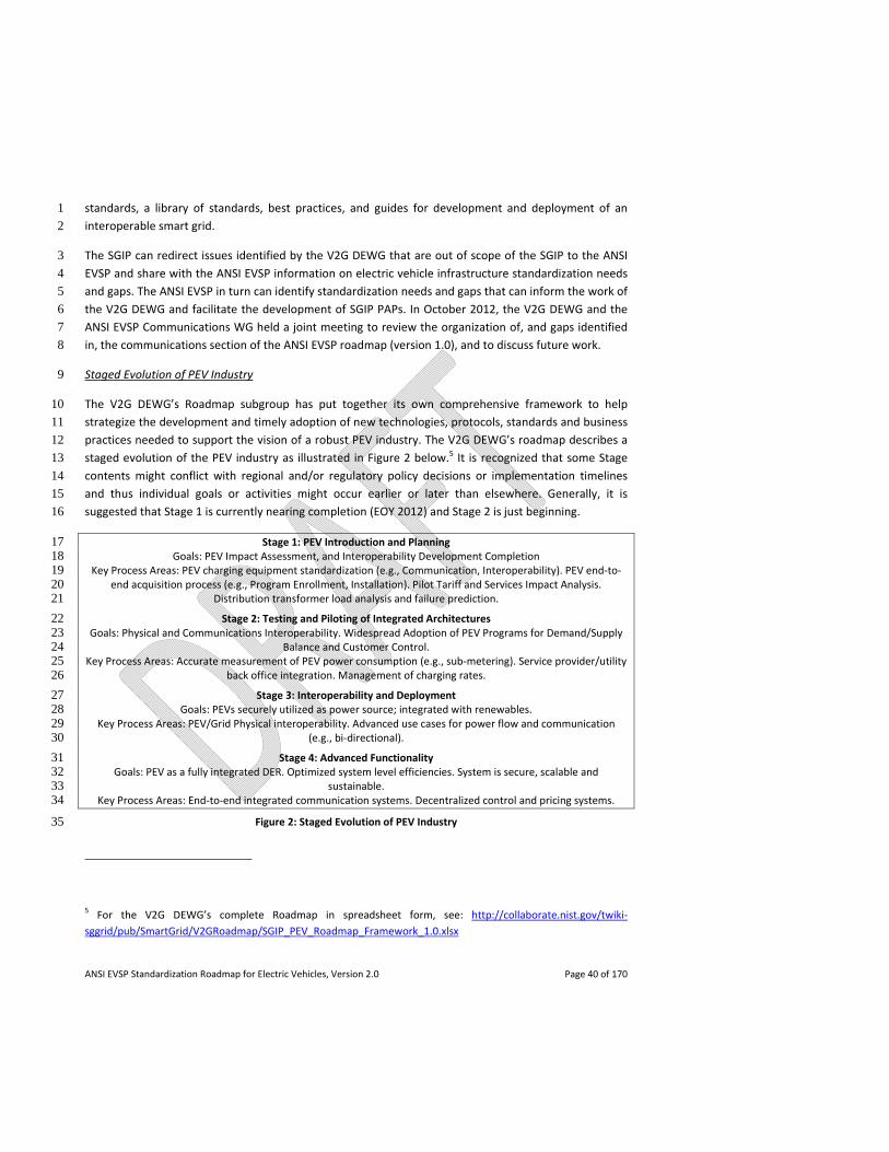
ANSI EVSP Standardization Roadmap for Electric Vehicles, Version 2.0 Page 40 of 170
standards, a library of standards, best practices, and guides for development and deployment of an 1
interoperable smart grid. 2
The SGIP can redirect issues identified by the V2G DEWG that are out of scope of the SGIP to the ANSI 3
EVSP and share with the ANSI EVSP information on electric vehicle infrastructure standardization needs 4
and gaps. The ANSI EVSP in turn can identify standardization needs and gaps that can inform the work of 5
the V2G DEWG and facilitate the development of SGIP PAPs. In October 2012, the V2G DEWG and the 6
ANSI EVSP Communications WG held a joint meeting to review the organization of, and gaps identified 7
in, the communications section of the ANSI EVSP roadmap (version 1.0), and to discuss future work. 8
Staged Evolution of PEV Industry 9
The V2G DEWG’s Roadmap subgroup has put together its own comprehensive framework to help 10
strategize the development and timely adoption of new technologies, protocols, standards and business 11
practices needed to support the vision of a robust PEV industry. The V2G DEWG’s roadmap describes a 12
staged evolution of the PEV industry as illustrated in Figure 2 below.5 It is recognized that some Stage 13
contents might conflict with regional and/or regulatory policy decisions or implementation timelines 14
and thus individual goals or activities might occur earlier or later than elsewhere. Generally, it is 15
suggested that Stage 1 is currently nearing completion (EOY 2012) and Stage 2 is just beginning. 16
Stage 1: PEV Introduction and Planning 17 Goals: PEV Impact Assessment, and Interoperability Development Completion 18
Key Process Areas: PEV charging equipment standardization (e.g., Communication, Interoperability). PEV end‐to‐19 end acquisition process (e.g., Program Enrollment, Installation). Pilot Tariff and Services Impact Analysis. 20
Distribution transformer load analysis and failure prediction. 21
Stage 2: Testing and Piloting of Integrated Architectures 22 Goals: Physical and Communications Interoperability. Widespread Adoption of PEV Programs for Demand/Supply 23
Balance and Customer Control. 24 Key Process Areas: Accurate measurement of PEV power consumption (e.g., sub‐metering). Service provider/utility 25
back office integration. Management of charging rates. 26
Stage 3: Interoperability and Deployment 27 Goals: PEVs securely utilized as power source; integrated with renewables. 28
Key Process Areas: PEV/Grid Physical interoperability. Advanced use cases for power flow and communication 29 (e.g., bi‐directional). 30
Stage 4: Advanced Functionality 31 Goals: PEV as a fully integrated DER. Optimized system level efficiencies. System is secure, scalable and 32
sustainable. 33 Key Process Areas: End‐to‐end integrated communication systems. Decentralized control and pricing systems. 34
Figure 2: Staged Evolution of PEV Industry 35
5 For the V2G DEWG’s complete Roadmap in spreadsheet form, see: http://collaborate.nist.gov/twiki‐
sggrid/pub/SmartGrid/V2GRoadmap/SGIP_PEV_Roadmap_Framework_1.0.xlsx
ANSI EVSP Standardization Roadmap for Electric Vehicles, Version 2.0 Page 41 of 170
In Figure 2, the Stage titles express broad statements about the overarching timeline activities they 1
represent. The Goals are meant to define gating factors so that the next stage can begin. The Key 2
Process Areas give an overview of what must be focused on to meet the Goals. Each of the Key Process 3
Areas includes additional specific activities or objectives (see link below) that ensure the completion of 4
the Key Process Areas and thus the Goals. These are organized under three headings: System 5
Functionalities (Integrated Communications, Distributed Energy Resources, Measurement, Advanced 6
Control Methods, Consumer Interfaces), System Qualities (Safety/Reliability, Security, Privacy) and 7
Market Structures (Role of Third Parties, Billing, and Regulatory and Business Practices). 8
TransAtlantic Business Dialogue: The TABD has supported the development of an EV agenda as an 9
advisor to the Transatlantic Economic Council (TEC). In March 2011, TABD members Audi and Ford 10
drafted an eMobility Work Plan for the TEC. ACEA (the European Automobile Manufacturers 11
Association), the Alliance of Automobile Manufacturers and others provided input and the plan was 12
endorsed by the TABD. In May 2011, the plan was submitted to the TEC Co‐Chairs within the White 13
House and the European Commission. It was further refined in preparation for the November 2011 TEC 14
meeting. The October 2011 ANSI – ESO Conference on Transatlantic Standardization Partnerships 15
included a session on eMobility/Electric Vehicles, organized in partnership with the TABD. At that event, 16
EU Trade Commissioner Karel De Gucht called on participants to organize a transatlantic eMobility 17
standardization roundtable. ANSI, CEN and CENELEC convened such a roundtable in Brussels in 18
November 2012. In December 2012, the TABD merged with the European‐American Business Council to 19
form the Transatlantic Business Council (TBC) with TABD operating as a distinct program within the new 20
organization. 21
National Electric Transportation Infrastructure Working Council: Sponsored by the Electric Power 22
Research Institute (EPRI), the IWC is a group of individuals whose organizations have a vested interest in 23
the emergence and growth of the EV and PHEV industries, as well as the electrification of truck stops, 24
ports, and other transportation and logistic systems. IWC members include representatives from electric 25
utilities, vehicle manufacturing industries, component manufacturers, government agencies, related 26
industry associations, and standards organizations. IWC committees meet several times a year. 27
Electric Drive Transportation Association: EDTA is an industry association dedicated to advancing 28
electric drive as a foundation for sustainable transportation. Since 1989, EDTA has led efforts to provide 29
federal support for electric drive research, demonstration and manufacturing, and to provide significant 30
incentives for the purchase of electric vehicles and chargers, and the promotion of EV infrastructure 31
development in the U.S. 32
Regional and State Initiatives: There are multi‐stakeholder and government supported efforts 33
underway at the regional, state and municipal level to facilitate the rollout of EVs. Some examples 34
include the following: 35
Northeast Electric Vehicle Network 36
The Transportation and Climate Initiative (TCI) of the Northeast and Mid‐Atlantic states, which is 37
facilitated by Georgetown University’s Climate Center, launched the Northeast Electric Vehicle Network 38
ANSI EVSP Standardization Roadmap for Electric Vehicles, Version 2.0 Page 42 of 170
in October 2011 to support the rollout of EVs in that region. TCI, together with the New York State 1
Energy Research and Development Authority (NYSERDA) and sixteen of the Northeast region’s Clean 2
Cities Coalitions, received a grant from the U.S. Department of Energy (DOE) to lay the groundwork for 3
the Northeast Electric Vehicle Network. Under the DOE grant, the project partners have engaged 4
stakeholders and conducted a literature review of market barriers to EV deployment in the Northeast. 5
They have also created several guidance documents for the TCI region including, among others, siting 6
and design guidelines for electric vehicle supply equipment, a report on EV‐ready codes for the built 7
environment, and a guide to planning and policy tools for creating EV‐ready towns and cities. See 8
www.northeastevs.org. 9
California Plug‐in Electric Vehicle Collaborative 10
The California Plug‐In Electric Vehicle (PEV) Collaborative is a multi‐stakeholder public‐private 11
partnership working to enable the plug‐in electric vehicle market in California. The Collaborative 12
includes elected and appointed officials, automakers, utilities, infrastructure providers, environmental 13
organizations, research institutions and others. The Collaborative has developed a strategic plan Taking 14
Charge for California’s PEV market through 2020 and formed a number of working groups to implement 15
the plan’s recommendations. The Collaborative has held workshops for local government officials to 16
support regional planning and local market development. It has also launched a number of reports, 17
communication guides, and a resource center to support these efforts. See www.pevcollaborative.org. 18
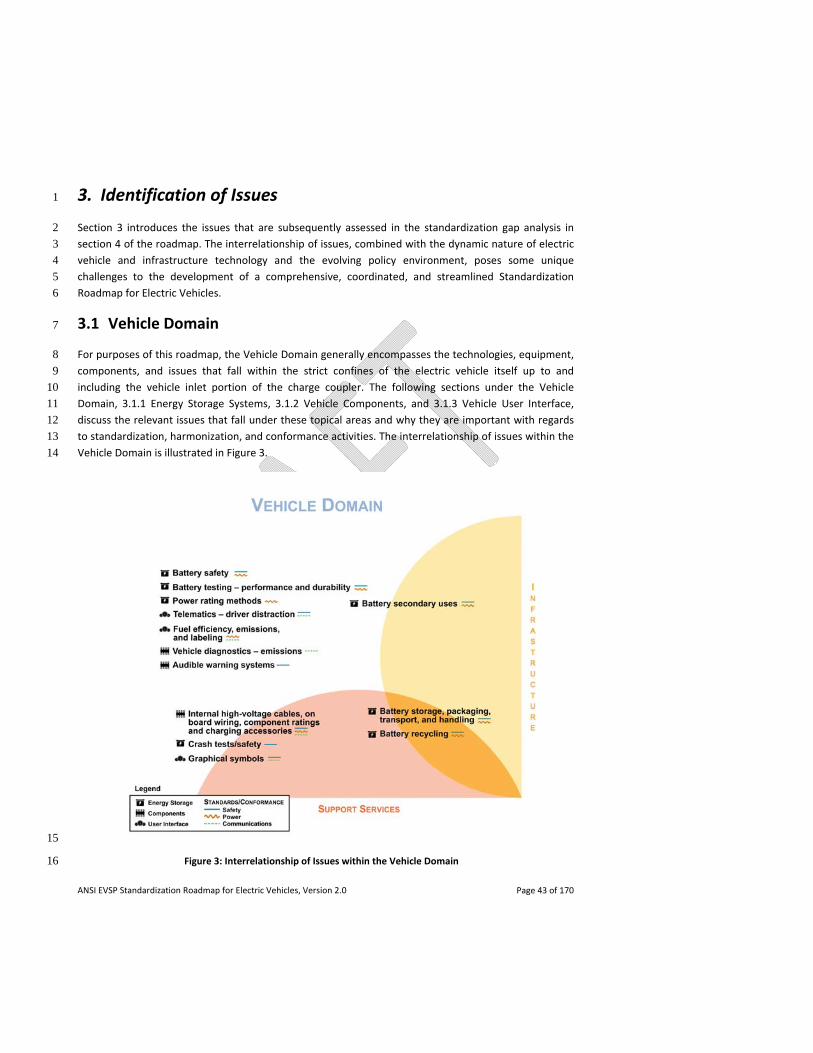
ANSI EVSP Standardization Roadmap for Electric Vehicles, Version 2.0 Page 43 of 170
3. Identification of Issues 1
Section 3 introduces the issues that are subsequently assessed in the standardization gap analysis in 2
section 4 of the roadmap. The interrelationship of issues, combined with the dynamic nature of electric 3
vehicle and infrastructure technology and the evolving policy environment, poses some unique 4
challenges to the development of a comprehensive, coordinated, and streamlined Standardization 5
Roadmap for Electric Vehicles. 6
3.1 Vehicle Domain 7
For purposes of this roadmap, the Vehicle Domain generally encompasses the technologies, equipment, 8
components, and issues that fall within the strict confines of the electric vehicle itself up to and 9
including the vehicle inlet portion of the charge coupler. The following sections under the Vehicle 10
Domain, 3.1.1 Energy Storage Systems, 3.1.2 Vehicle Components, and 3.1.3 Vehicle User Interface, 11
discuss the relevant issues that fall under these topical areas and why they are important with regards 12
to standardization, harmonization, and conformance activities. The interrelationship of issues within the 13
Vehicle Domain is illustrated in Figure 3. 14
15
Figure 3: Interrelationship of Issues within the Vehicle Domain 16
ANSI EVSP Standardization Roadmap for Electric Vehicles, Version 2.0 Page 44 of 170
Terminology 1
On a general note from the outset, it is important for consistent vocabulary to be used for electric 2
vehicle terminology to assist in the development of standards for electric vehicles, as this will provide a 3
consistent understanding of important concepts. 4
3.1.1 Energy Storage Systems 5
The topical area of Energy Storage Systems primarily relates to battery energy storage and related 6
subsystems but may also include other energy storage systems, including fuel cells and mechanical 7
energy storage. The most common types of batteries being developed for electric transportation are 8
lithium‐ion‐based. Topics addressed in this section include: power rating methods; battery safety; 9
battery testing – performance and durability; battery storage, packaging, transport and handling; 10
battery recycling; battery secondary uses; and crash tests/safety. 11
3.1.1.1 Power Rating Methods 12
Power rating methods are important for hybrid electric vehicles and battery‐powered all electric 13
vehicles in order to define test methods and conditions for rating the performance of electric propulsion 14
motors as used in these vehicles, as well as thermal and battery capabilities and limitations. 15
3.1.1.2 Battery Safety 16
For electric vehicles to meet their full potential in the marketplace, the public needs to see them as at 17
least as safe as the vehicles they replace. Effective safety standards provide a means to ensure that 18
electric vehicles are safe for occupants, other motorists, children, service technicians, and first 19
responders. Safety standards mainly consist of tests, intended to duplicate real‐world events. 20
Compliance to an EV battery safety standard demonstrates that the EV battery meets a minimum safety 21
criteria established by that standard. Safety standards not only protect the public – they also help 22
protect manufacturers from legal challenges that may arise. Vehicle manufacturers desire global 23
harmonization of safety standards that are effective without imposing unnecessary costs or limits to 24
innovation. 25
3.1.1.3 Battery Testing – Performance and Durability 26
Battery performance and durability testing incorporates a means to evaluate both the performance and 27
durability of cells, modules and full battery packs, as well as the battery management system. Test 28
standards related to battery abuse, product safety, or transportation/handling are addressed in other 29
sections of the Energy Storage Systems topical area of this roadmap. 30
ANSI EVSP Standardization Roadmap for Electric Vehicles, Version 2.0 Page 45 of 170
3.1.1.4 Battery Storage, Packaging, Transport and Handling 1
Battery Storage 2
EV Batteries (including HEV and PHEV) will require storage throughout many stages of their life cycle, 3
namely – prior to market distribution by manufacturers, in import/export locations, logistic centers, in 4
battery swapping (switching) stations including warehousing, in repair workshops as well as garages 5
following accidents, at recovered vehicle storage lots, at auto salvage yards, and at the end‐of‐life in 6
recycling facilities. Traceability and life cycle management are important. Differentiation between new 7
and waste batteries (damaged, aged, sent for repair, end‐of‐life) batteries is also significant. The risk of a 8
stored battery must be evaluated based on several parameters, including, but not limited to, state of 9
charge (SOC), mechanical wholeness, and age of the battery. 10
Battery storage issues of concern include: high temperature controls (particularly significant for battery 11
swapping stations during charging), humidity control including adequate air circulation and ventilation 12
to prevent explosive gas atmospheres (especially significant for damaged batteries), hydrogen/oxygen 13
detection, storage of damaged batteries away from other batteries and combustible materials, and fire 14
prevention and extinguishing systems. 15
Battery Packaging, Transport and Handling 16
Three significant use cases exist with respect to battery packaging, transport and handling: 17
- Battery packaging and design for the transportation between the battery manufacturer and the 18
vehicle manufacturer; 19
- Battery packaging and design for battery transportation to workshops or battery swapping 20
stations; and 21
- Battery packaging for the transportation of used and damaged batteries. 22
Transport by ground, air and sea of EV batteries (including those for HEVs and PHEVs) presents a unique 23
risk to their supply chain handlers, as their weight and volume are significantly higher than common 24
consumer batteries. This risk grows further when handling aged and damaged batteries. For example, 25
there may be needed packaging for a damaged or deformed battery to account for possible leakage of 26
materials. 27
3.1.1.5 Battery Recycling 28
Battery end‐of‐life, either through damage beyond repair or full exhaustion following use, requires 29
special consideration from the environmental, geo‐political and economical points of view. As electric 30
vehicle battery manufacturing relies on natural minerals mining and improper disposal may potentially 31
result in soil, groundwater and air pollution, the need for technology allowing for efficient battery 32
recycling is fast growing. Lead‐acid batteries, by comparison, have reached nearly 100% recycling rates 33
worldwide. 34
ANSI EVSP Standardization Roadmap for Electric Vehicles, Version 2.0 Page 46 of 170
Lithium‐based batteries are expected to be the main chemistry for the foreseeable future, and are 1
projected to take up nearly 40% of the consumable world lithium by 2020. Positive value for recycling 2
these batteries is likely to be through the nickel and cobalt components, as the lithium itself is a small 3
fraction of the battery, and rather inexpensive. Additional challenges stem from the fact that many 4
battery chemistries exist with different lithium combinations and pack geometries, which makes it hard 5
to develop industrial‐scale precise recycling processes with high recovery rates and efficiency. 6
Additionally, not all battery chemistries may have a value (e.g., iron phosphate). 7
3.1.1.6 Battery Secondary Uses 8
A secondary life for both fixed and removable electric vehicle batteries may include re‐use for other 9
vehicular applications and grid and low‐power applications. This can include fulfilling different grid 10
functionalities including storing energy and helping to stabilize grids utilizing renewable energy. 11
Some possible battery second life applications include: 12
- Re‐use or repackaging of modules or packs with testing for compatibility in vehicle applications; 13
- Re‐use for lower power applications especially DC and home to grid and vehicle to grid, etc.; 14
- Re‐use in industrial situations utilizing DC energy for manufacturing with low voltage use and 15
storage; 16
- Re‐use with alternative power in small farm or school type uses, and as battery backup and 17
stable power source; 18
- Re‐use with alternative power in medium factory or building uses, and as battery backup and 19
stable power source; 20
- Re‐use for grid support, line balancing and backup stabilization. 21
The nascent second life market for EV batteries has the potential to lower the cost of electro‐mobility 22
and enhance environmental protection through materials retention, re‐use, and extended battery pack 23
life, leading to value chain enhancements. 24
3.1.1.7 Crash Tests / Safety 25
To be sold in the U.S., electric vehicles must comply with all applicable Federal Motor Vehicle Safety 26
Standards (FMVSS). These include crash avoidance standards, crashworthiness standards, post‐crash 27
safety standards and others. The FMVSS are enforced by NHTSA, which routinely conducts compliance 28
testing to ensure that the vehicles certified for sale in the U.S. comply with all of the applicable 29
requirements. Vehicles that are noncompliant or vehicles that possess a safety defect are subject to 30
NHTSA’s recall and remedy provisions of the Motor Vehicle Safety Act. 31
ANSI EVSP Standardization Roadmap for Electric Vehicles, Version 2.0 Page 47 of 170
3.1.2 Vehicle Components 1
Key on‐board vehicle areas addressed within this roadmap include: safety issues associated with internal 2
high voltage cables and on‐board wiring, component ratings, and charging accessories; vehicle 3
diagnostics – emissions; and audible warning systems. 4
3.1.2.1 Internal High Voltage Cables, On‐Board Wiring, Component Ratings and Charging 5
Accessories 6
The advent of the electric vehicle poses unique opportunities and challenges from a safety perspective. 7
In terms of vehicle component standards, the high voltage cables entail the primary conductive media 8
internal to the vehicle. This area does not include the cabling systems commonly used in 12V and 24V 9
systems that form the basic wiring systems in conventional vehicles. Instead, this topic focuses on the 10
systems and subsystems associated with the primary drive mechanisms for the vehicle. For hybrid 11
electric vehicles, this includes the cabling associated with any electricity transferred from the internal 12
combustion engine to the storage device, as well as regenerative braking technology and the charging 13
station. For plug‐in electric vehicles, this is only the braking and charging connections to the drive train. 14
Both AC and DC technologies are considered. Concerns over the internal, high voltage cables relate to 15
both the safety of the operator and the integrity and efficiency of the propulsion and storage systems 16
for the EV. 17
3.1.2.2 Vehicle Diagnostics – Emissions 18
An issue for plug‐in hybrid electric vehicles and hybrid electric vehicles (but not for battery‐powered all 19
electric vehicles), is vehicle diagnostics with respect to the detection of system faults within the vehicle’s 20
emissions control system. 21
3.1.2.3 Audible Warning Systems 22
Organizations of, and for, persons who are blind or have low vision have expressed concerns that 23
electric vehicles and some hybrid electric vehicles may not be audibly detectable by the blind. Safety 24
standards related to sound emission/audible warning systems can serve to address this concern. 25
3.1.3 Vehicle User Interface 26
A reliable, safe customer experience is critical to electric vehicles gaining acceptance in the marketplace. 27
One step toward improving this experience is using communication tools that are readily identifiable 28
and understood by the vehicle owner and those that service or otherwise interact with the vehicle. 29
Topics addressed in this section include: graphical symbols; telematics – driver distraction; and fuel 30
efficiency, emissions, and labeling. 31
ANSI EVSP Standardization Roadmap for Electric Vehicles, Version 2.0 Page 48 of 170
3.1.3.1 Graphical Symbols 1
Due to the global nature of the industry, the use of universal graphical symbols that are easily 2
understood regardless of the language of the driver will assist in effective communication of such 3
important information as the battery fuel gauge, state of charge, and health. 4
3.1.3.2 Telematics – Driver Distraction 5
Telematics is the combination of telecommunication and programmable computerized services to assist 6
drivers with navigation, emergency assistance, convenience features such as remote door locks, climate 7
conditioning, access to internet/cloud services, on‐board diagnostics, service reminders, and other 8
infotainment services. This section discusses driver interaction with such information and 9
communications systems, and more specifically the potential for driver distraction from the task of 10
driving. 11
3.1.3.3 Fuel Efficiency, Emissions, and Labeling 12
Fuel economy and vehicle emissions are among several factors that consumers will evaluate in deciding 13
whether or not to purchase an electric vehicle. It is therefore important that vehicle labels provide clear 14
and accurate information. As more electric vehicles appear on the market, it will become increasingly 15
important for consumers to be able to compare among different manufacturers and models. Consumers 16
will also want to compare and contrast features and value across the different types of available EVs 17
(AEVs, PHEVs, HEVs) in the same way that they have traditionally evaluated vehicles powered by internal 18
combustion engines. 19
3.2 Infrastructure Domain 20
For purposes of this roadmap, the Infrastructure Domain generally encompasses the technologies, 21
equipment, components, and issues that fall within the confines of the charging infrastructure up to and 22
including the connector portion of the charge coupler. The following sections under the Infrastructure 23
Domain, 3.2.1 Charging Systems, 3.2.2 Infrastructure Communications, and 3.2.3 Infrastructure 24
Installation, discuss the relevant issues that fall under these topical areas and why they are important 25
with regards to standardization, harmonization, and conformance activities. The interrelationship of 26
issues within the Infrastructure Domain is illustrated in Figure 4. 27
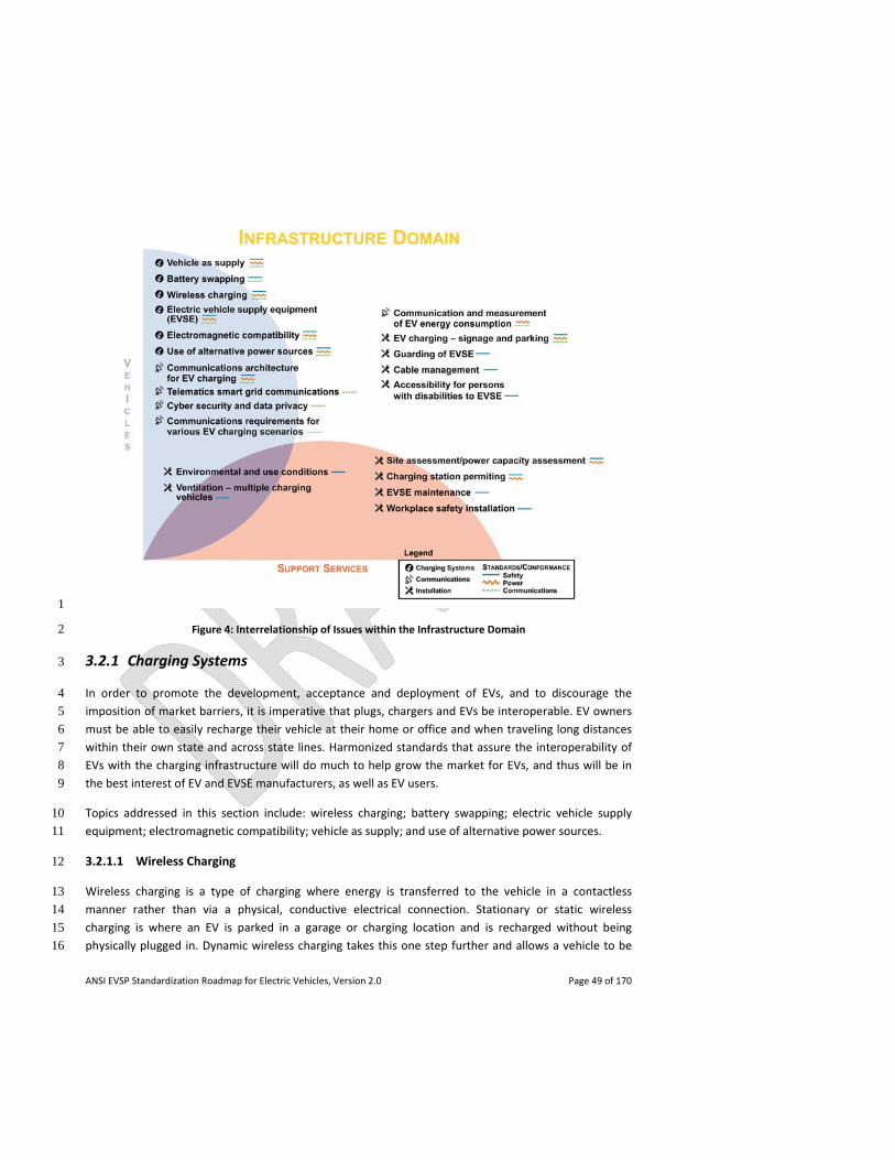
ANSI EVSP Standardization Roadmap for Electric Vehicles, Version 2.0 Page 49 of 170
1
Figure 4: Interrelationship of Issues within the Infrastructure Domain 2
3.2.1 Charging Systems 3
In order to promote the development, acceptance and deployment of EVs, and to discourage the 4
imposition of market barriers, it is imperative that plugs, chargers and EVs be interoperable. EV owners 5
must be able to easily recharge their vehicle at their home or office and when traveling long distances 6
within their own state and across state lines. Harmonized standards that assure the interoperability of 7
EVs with the charging infrastructure will do much to help grow the market for EVs, and thus will be in 8
the best interest of EV and EVSE manufacturers, as well as EV users. 9
Topics addressed in this section include: wireless charging; battery swapping; electric vehicle supply 10
equipment; electromagnetic compatibility; vehicle as supply; and use of alternative power sources. 11
3.2.1.1 Wireless Charging 12
Wireless charging is a type of charging where energy is transferred to the vehicle in a contactless 13
manner rather than via a physical, conductive electrical connection. Stationary or static wireless 14
charging is where an EV is parked in a garage or charging location and is recharged without being 15
physically plugged in. Dynamic wireless charging takes this one step further and allows a vehicle to be 16
ANSI EVSP Standardization Roadmap for Electric Vehicles, Version 2.0 Page 50 of 170
recharged while in motion. Wireless charging is a rapidly developing technology that will lend itself 1
naturally in the promotion and deployment of EVs. Although at this time the standards for wireless 2
charging are not complete, there is a significant interest in this technology. It is important to have 3
harmonized standards to ensure a safe, interoperable charging experience. 4
3.2.1.2 Battery Swapping 5
The limited range of current plug‐in electric vehicles is a major obstacle when it comes to consumer 6
adoption and the migration from traditional internal combustion engine powered transportation 7
solutions to a clean battery powered solution. The current estimated range of battery‐powered all 8
electric vehicles is around 80‐120 miles with a battery weight of around 550‐600 pounds. In a plug‐in 9
hybrid electric vehicle, range can be extended via a gas‐powered generator. In general, the current 10
range of PEVs on battery power alone is satisfactory for most daily commuter driving, but it does not 11
provide the ability to drive long distances, hence the need for range extension. Accordingly, there is a 12
need for a supporting infrastructure of charging networks covering homes, offices, parking, shopping 13
and industrial areas, and highways where PEVs can plug‐in to recharge. 14
An alternative approach to addressing the range extension issue is via a network of battery swapping 15
(switching) stations (BSS). A BSS is an electro‐mechanical installation of robotics, electrical and 16
mechanical drives used for the switching of batteries for electric vehicles and that may include battery 17
charging devices and telecommunication ports. This technology exists today and has been used in niche 18
segments for many years, enabling the replacement of a depleted battery with a fully charged one in 19
less than 5 minutes. The fully automated process removes the battery from the vehicle and moves it to a 20
battery rack, so the battery can be charged in optimal conditions. A fully charged battery is then taken 21
from the battery rack and inserted into the vehicle. Battery swapping stations could be located along all 22
key highways or major roads, thus enabling electric vehicles to drive for extended ranges. Battery 23
swapping stations are currently being mass deployed in Israel, Denmark, and China. 24
Battery swapping technology would require removable batteries with common interfaces that connect 25
with the battery outside the vehicle. EV batteries are currently very heavy, which requires that they be 26
carefully handled. Therefore, removable batteries will require a common mechanical interface to lock 27
and remove the battery from the vehicle by actuation of "twist‐like" devices by external actuators which 28
are part of a switching station. Other issues pertinent to common battery packs and modules include 29
electrical interface, cooling integration, data transfer integration and dimensions. 30
3.2.1.3 Electric Vehicle Supply Equipment (EVSE) 31
Power Quality 32
Plug‐in electric vehicles require both the electric grid and the vehicle charger to be reliable, as the power 33
quality of one depends on the power quality of the other. Coordinating the electric utility grid 34
characteristics and acceptable levels of power quality for vehicles and vehicle chargers allows 35
manufacturers and utilities to ensure that PEV users achieve a reliable charging experience. 36
ANSI EVSP Standardization Roadmap for Electric Vehicles, Version 2.0 Page 51 of 170
EVSE Charging Levels/Modes 1
One of the most critical components to electric vehicle adoption is the ease and efficiency by which the 2
vehicle can be recharged, and the availability of charging facilities. The most available means of charging 3
an electric vehicle is to use a standard grounded electrical receptacle in accordance with NEC® Article 4
625 requirements. This is most practical at home where receptacle outlets are readily available and 5
downtime for the vehicle potentially allows the longest charging period throughout the day. Charging at 6
higher AC voltages, or using DC voltages, can provide a faster charge. These AC voltage levels are 7
available in homes, as well as municipalities, workplaces, and retail locations. DC chargers and high 8
power AC supply equipment can provide high power charging, reducing the time it takes to charge a 9
vehicle. 10
EV Supply Equipment and Charging Systems 11
As defined in Article 625 of the National Electrical Code®, electric vehicle supply equipment (EVSE) 12
includes off‐board charging stations, or portable EV cord sets (also referred to as charge cables) that 13
supply AC power to a vehicle’s on‐board charger, whereas EV charging system equipment includes off‐14
board chargers that supply DC power to a vehicle in order to charge the on‐board storage battery 15
directly. Vehicles may be designed for use with both types of infrastructure equipment. On‐board 16
systems and controls are required to maintain the proper charge path such that AC voltages are not 17
applied to the battery and the like. 18
Infrastructure equipment is provided with a system of protection that is used to monitor ground 19
connections or isolation of the charging circuit from the user. These systems monitor the infrastructure 20
device as well as the vehicle through the conductive connection. The protection systems provide a 21
portion of the control for the charging function and shut down the infrastructure equipment in the 22
event of a loss of the protective elements associated with that system of protection (ground or 23
isolation). 24
EV Couplers 25
A critical user component required for recharging plug‐in electric vehicles is the EV coupler, which 26
consists of a vehicle connector and a vehicle inlet. This vehicle connector and vehicle inlet combination 27
(coupler) provides a conductive path for power from the charging infrastructure equipment to the 28
vehicle, and assists the infrastructure equipment with safety checks, communication, and other aspects 29
associated with safe recharging of the vehicle. 30
Ideally, electric vehicle operators should be able to use any available charging station to recharge their 31
vehicle. This interoperability is governed by the electric vehicle charging systems including the vehicle 32
couplers. For these reasons, standardized EV couplers are vitally important in facilitating public adoption 33
of EVs, especially when multiple vehicle models are involved. 34
The EV coupler is also instrumental in protecting people from the risk of electric shock. This includes the 35
vehicle owner, as well as other people in the area that may contact the electric vehicle or the EV 36
ANSI EVSP Standardization Roadmap for Electric Vehicles, Version 2.0 Page 52 of 170
coupler. The EV coupler also protects the vehicle, by guarding against mismatching of the vehicle 1
connector and vehicle inlet and providing for the correct communication and pilot controls via an 2
expected charge protocol. Safety standards provide the minimum requirements necessary to protect the 3
vehicle owner, general public, infrastructure, garage, and charging site while the vehicle is charging. 4
With standardized couplers, an EV driver would be familiar with one type of EV connector and would not 5
have to worry about matching a connector to their particular vehicle make and model. Standardization 6
would also reduce attempts to modify equipment, or provide adapters to convert equipment, which 7
could adversely affect the safety of the charging system. Harmonized standards (national, regional, 8
international) would be beneficial, so that all EV couplers and electric vehicles would function in the 9
same manner and provide similar protection. 10
3.2.1.4 Electromagnetic Compatibility (EMC) 11
The concept of EMC is to protect both the communications channels and the electrical circuits used in 12
charging and operating the vehicle. The focus is to limit or control electromagnetic emissions by both 13
the vehicle and charging station devices to keep them within tolerable limits for other nearby devices. 14
EMC standards help maintain the integrity of the EV system as a potential emitter and “good citizen” of 15
the electric grid, as well as protecting the vehicle and charging station from other emitters on the grid. 16
This is necessary to maintain the safety and interoperability of the devices within the charging 17
environment. 18
3.2.1.5 Vehicle as Supply 19
The topic of vehicle as supply describes the vehicle serving as a power source for other than vehicle 20
applications. Reverse power flow (RPF) is when the EV transfers power to off‐board equipment as 21
further described below. 22
Pure reverse flow is very useful for powering loads at a remote site; this capability is called Vehicle to 23
Load (V2L). An EV can also use pure reverse power flow for providing a “jump start” to another EV; this 24
capability is called Vehicle to Vehicle (V2V). And pure reverse flow from an EV can be used to provide 25
emergency backup power for a home following a loss of grid power; this is called Vehicle to Home (V2H). 26
Because these are all off‐grid applications, the on‐board or external inverter must regulate both the 27
voltage and the frequency and it is the connected loads that determine how much energy flows from 28
the vehicle battery. 29
When a vehicle provides reverse power flow into a live electric grid this is called Vehicle to Grid (V2G). A 30
small, modular storage device connected to the grid is considered to be a distributed energy resource 31
(DER). The grid‐connected EV that is capable of reverse power flow is a DER device. The real value of an 32
EV to the grid is its ability to serve as a DER device and provide precisely controlled bi‐directional power 33
flow – not just reverse flow. The bi‐directional converter can be located on‐board the vehicle or 34
externally in the EVSE. When the grid‐tied bi‐directional converter is providing power to the grid it must 35
operate as a current source, synchronized to the grid voltage and frequency. The grid‐tied bi‐directional 36
converter can be commanded to deliver a precise forward or reverse power flow. If there is a power 37
ANSI EVSP Standardization Roadmap for Electric Vehicles, Version 2.0 Page 53 of 170
failure, the inverter must automatically turn off. This is for the safety of workers that may be repairing 1
downed lines. 2
The term V2G has become associated with the concept of an aggregator coordinating the power flow of 3
many EVs to provide frequency regulation for the grid. This is only one of many ways that an EV can 4
serve the bulk grid and the distribution system as a DER. An EV with DER capability can be used solely 5
within a home by a home energy management system to manage the power demand of the home on 6
the external grid. This is not a V2H application because the home loads are still connected to a live grid. 7
However, a grid‐tied inverter system can be configured to automatically disconnect the home from the 8
grid and switch from V2G to V2H operating mode following a grid power failure. This is routinely done 9
today with grid‐tied solar PV inverter systems. 10
An EV could route power from an on‐board inverter to a vehicle‐mounted panel with NEMA receptacles. 11
This would be very convenient for directly connecting tools or appliances to the panel for V2L or using a 12
cord set for V2V. The EV could also be connected to the home through a transfer switch in the same 13
manner as any other portable genset to provide V2H capability. The EV to EVSE connection would be 14
used for V2G. 15
An external inverter would use the EV to EVSE connection and extract DC power from the vehicle 16
battery to generate the AC power. A premises‐mounted EVSE could be used for V2G and V2H modes 17
with automatic switching. A portable unit could be used for V2L and V2V applications. 18
3.2.1.6 Use of Alternative Power Sources 19
EVs support and complement the increased possibility of an infrastructure with distributed generation 20
of power, and direct connection of power sources to the EV for charging purposes. This includes 21
efficiency benefits of DC generation and DC use, without losses associated with conversion to and from 22
AC, for example use of photovoltaic (PV) for direct DC charging of electric vehicles. It also allows the EV 23
battery to serve as a storage device for alternative energy systems, for example solar power generated 24
during the day or wind power generated at night, which can be reclaimed later as needed. 25
3.2.2 Infrastructure Communications 26
The charging of EVs creates both risks and opportunities for service providers and consumers. At a 27
minimum, consumers want access to a ubiquitous charging infrastructure that enables them to charge 28
their EVs safely and quickly at the cheapest possible rate. Energy Service Providers want to be able to 29
push charging to off‐peak hours to protect grid assets. 30
Additionally, value‐added services such as demand response/load control, pricing, locating and reserving 31
charging stations, reverse energy flow, and charge management can provide further benefits to 32
consumers and the grid. To advance a truly smart grid that can accommodate EVs, it is necessary that 33
communication among the various entities involved be enabled to maximize the services offered and 34
the benefits that EVs can deliver. Put another way, the vehicles, charging network providers and utilities 35
ANSI EVSP Standardization Roadmap for Electric Vehicles, Version 2.0 Page 54 of 170
must be able to interact with one another seamlessly. While standards are a critical part of this, business 1
models are also needed to support the infrastructure for these interactions. 2
Topics discussed in this section include: communications architecture for EV charging; communications 3
requirements for various EV charging scenarios; communication and measurement of EV energy 4
consumption; cyber security and data privacy; and telematics smart grid communications. 5
Standardization work that relates generally to smart device communications, the connected vehicle, and 6
intelligent transportation systems is beyond the scope of this roadmap. Rather, this communications 7
section is focused on standards that are essential or unique to the PEV charging infrastructure, such as 8
those governing communications among an EV, EVSE and an Energy Service Provider. 9
Appendix A contains a more detailed, high level description of the need for communications in different 10
sections of the EV charging infrastructure, and the various stakeholders or actors involved in PEV 11
charging that need to communicate with each other. 12
3.2.2.1 Communications Architecture for EV Charging 13
The actors and communication methods involved in EV charging may vary, depending on criteria such as 14
the location of charging; the EV‐related infrastructure (communications‐capable or not); the type of 15
charging (AC/DC/wireless); the charging provider (utility, corporation, municipality, EV Services Provider, 16
etc.); and the requirements for authentication, authorization, accounting, and billing of the charging 17
session. 18
An actor is an entity that serves as one end point of communications. For example, when an EV 19
communicates with an EVSE, the two actors are the EV and the EVSE. The primary actors involved in EV‐20
related communication are expected to be the: (1) EV, (2) EV driver / operator, (3) EVSE, (4) Energy 21
Service Provider (ESP), (5) Energy Management System (EMS), (6) End Use Measurement Device 22
(EUMD), and (7) EV Services Provider (EVSP). 23
Figure 5 shows a sample communications‐oriented architecture containing the primary actors, including 24
three different locations where charging may occur. 25
EV charging infrastructure is a subset of the electric grid or smart grid. For simplicity, the generation, 26
transport and distribution parts of the grid can be bundled up and referred to as the utility or Energy 27
Service Provider. 28
Broadly speaking, EV charging infrastructure downstream from the utility may be subdivided into home 29
(residential) charging, public charging and commercial charging. 30
In all these scenarios, the utility, the EV, and in most cases the EVSE are the constants. 31
Home Charging 32
For home charging, the utility may communicate directly with the smart meter(s) installed at the home. 33
These meters send consumption data to the utility, and the costs can be calculated according to the 34
tariff schedules. This scenario only requires communication between the smart meter (operated by the 35

ANSI EVSP Standardization Roadmap for Electric Vehicles, Version 2.0 Page 55 of 170
utility) and the utility. This could happen over the AMI (Advanced Measuring Infrastructure) network 1
deployed by the utility. 2
In a more advanced scenario, the EV may use the OEM's telematics network to download demand 3
response information and tariff rates, and schedule charging accordingly. 4
In cases where a jurisdiction (such as a public utilities commission) has mandated that sub‐metering be 5
opened up to third party agents, a sub‐meter that resides in the EVSE, EV, or outside of them needs to 6
communicate its metering data to the third party, and the third party needs to then forward that data 7
(as‐is or in an aggregated format) to the utility. 8
Home charging communication may happen over a Home Area Network, or it may use the customer's 9
internet connection, or it may use its own cellular data connection. 10
Commercial Charging 11
In scenarios where EVSEs are restricted to authorized access only EVs or EV drivers, then communication 12
is required for authentication purposes, e.g., using an RFID card, credit card, QR code, smartphone 13
application, etc. 14
The commercial charging scenario includes entities such as corporations, supermarkets, universities, 15
hospitals, etc. A commercial entity may offer different levels of service to different customers. For 16
instance, a supermarket may provide benefits to customers who charge at their EVSEs. Hospitals and 17
corporations may restrict EV charging to their employees only, in certain spaces. In other cases, charging 18
may be allowed for everyone. 19
The commercial charging scenario could also include MDUs (multi‐dwelling units such as apartment 20
complexes). If a small number of EVSEs are shared amongst all the EV driving residents of an MDU, then 21
the MDU operator may want to restrict access to those residents who sign up for a charging plan. 22
Public Charging 23
As EVs proliferate, there may be a large number of EV owners who do not have the luxury of charging at 24
home because they have to park their EVs on the street or they have to travel long distances. 25
Public charging may require the AAA (Authentication, Authorization and Accounting) function to be able 26
to bill the appropriate consumer, i.e., the consumer must be unambiguously identified such that the 27
proper service can be provided, and the service (electricity delivered to the EV) must be metered 28
accurately and securely, so that the consumer can be billed for their EV charging. 29
Also, since EVSEs are not ubiquitous, there needs to be a means for a driver to locate them, view 30
information (such as pricing and availability), and possibly reserve their use. 31
32
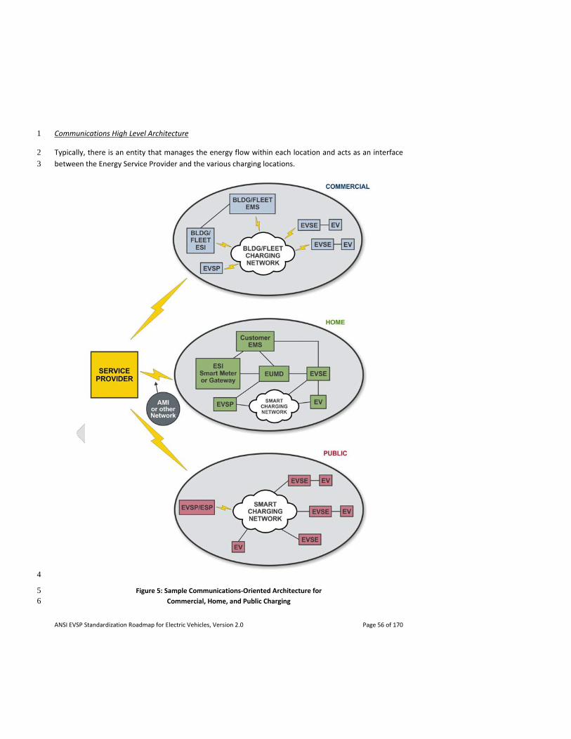
ANSI EVSP Standardization Roadmap for Electric Vehicles, Version 2.0 Page 56 of 170
Communications High Level Architecture 1
Typically, there is an entity that manages the energy flow within each location and acts as an interface 2
between the Energy Service Provider and the various charging locations. 3
4
Figure 5: Sample Communications‐Oriented Architecture for 5 Commercial, Home, and Public Charging 6
ANSI EVSP Standardization Roadmap for Electric Vehicles, Version 2.0 Page 57 of 170
In a home, an Energy Management System (EMS) could act as an analog of a building EMS and control 1
all the energy loads in the home, including EVs. While the external communication with the Energy 2
Service Provider uses an Energy Services Interface (ESI), communication between the EMS and the 3
internal charging infrastructure takes place via a Home Area Network (HAN). Optionally, an EV Services 4
Provider may manage the EV portion of the load, leaving the EMS to handle the remaining loads such as 5
air‐conditioning. 6
In the case of a commercial/industrial building, an EMS may be the entity managing the energy flow. It 7
communicates with the ESP via a standard ESI, and with the building's charging infrastructure via some 8
internal communications mechanism (e.g., BACnet). 9
For public charging stations, an EV Services Provider manages a network of EVSEs and provides charging 10
availability to EV drivers. The EVSP communicates with the ESP using a standard protocol such as 11
OpenADR 2.0 or ESPI, and may act as an aggregator, providing a single communication point with the 12
ESP for all the EVSEs in its purview. Creating and/or harmonizing standards specific to public charging 13
communication is desirable in order to provide services such as finding and reserving charging stations. 14
3.2.2.2 Communications Requirements for Various EV Charging Scenarios 15
There are various communication requirements for charging of EVs under different use cases (home, 16
commercial, public) and metering options, each with different levels of complexities. 17
Basic charging at home does not require communications. However, additional benefits become 18
available if smart charging capabilities exist, such as if sub‐metering, charge management and/or 19
demand response are implemented. Further communication complexities come into play if the EV is to 20
be used as a supply source providing reverse power flow to the home or grid. 21
Commercial / industry applications (e.g., fleets) often involve multiple vehicle charging scenarios with 22
load balancing and sequencing in order to meet business application requirements and minimize costs. 23
Accurate, real time coupling of state of charge (SOC) assessment, business application requirements, 24
and service provider demand response load control is essential. 25
Public charging communication requirements include the need to quickly and easily locate, price 26
compare, and reserve charging stations on the fly. Additional complexities are also introduced due to 27
the need to authenticate, authorize, and bill the user, especially when crossing over different service 28
territories. 29
The following briefly describes a number of the requirements for information/communication exchange, 30
not all of which are germane to each use case. 31
Locating and Reserving Charging Stations: EV drivers charging outside their home need to easily find and 32
optionally reserve an available, compatible charging station. In‐vehicle dashboard systems, portable 33
navigation devices, smart phones, and personal computers need to communicate with entities that can 34
provide these services. 35
ANSI EVSP Standardization Roadmap for Electric Vehicles, Version 2.0 Page 58 of 170
Charging Related Information Retrieval: EV drivers need to retrieve information about the current SOC 1
of their EV and an estimate of how long charging may take. Based on this information, the driver can 2
make an informed decision about where to charge, relieving range anxiety. This information is available 3
in the EV and needs to be communicated to the driver via standard mechanisms. 4
Pre‐Charging Information Exchange: In order for charging to take place, an EV must be physically 5
associated with an EVSE. At that point, charging parameters such as direction of energy flow, start and 6
end time of charging, price, and EV/driver authentication information need to be communicated 7
between the EV, EVSE, and grid. 8
During a Charging Session: For billing purposes, it is critical to accurately measure the energy being 9
provided to the EV and communicate this to the EVSP/ESP, optimally in real time. Charge management 10
including battery SOC is important. Energy Service Providers may need to act in real time during peak 11
demand situations by providing incentives to EVs to reduce the amount of energy consumed (demand 12
response load control). 13
Notifications: The EV driver may optionally opt‐in to receive notifications when charging is completed or 14
ends due to a fault. Such information needs to be communicated from the EV/EVSE to the driver. 15
Post‐Charging: At the end of a charging session, the EV driver/owner must be billed. This may involve 16
communications with a credit card processor, communication between an EVSP and an ESP, or 17
communication between two EVSPs (e.g., when roaming). 18
In order to successfully communicate the information required in the above scenarios, multiple actors, 19
protocols, and communication media may be involved. Each primary actor may be capable of 20
communicating via multiple methods. For example, an EV may be able to communicate with an EVSE 21
using power line communication (PLC) over the physical link between them. The EV may also be able to 22
communicate with an EV Telematics Provider using telematics communication over wireless cellular 23
radio (2G/3G/4G). 24
Due to the number of actors involved and services being offered, as well as the plethora of 25
communications technologies in service, it is critical to standardize these communications as much as 26
possible to provide ease of entry into the market while also allowing widespread and consistent 27
charging capabilities to drivers without adversely impacting the grid. Communications interoperability is 28
a critical component of a smart grid. 29
3.2.2.3 Communication and Measurement of EV Energy Consumption 30
Though not required for charging purposes, the measurement of EV energy consumption is deemed 31
necessary to provide customers certain value added services related to EV and HAN energy usage 32
information and control. Along with demand response (DR) programs, discrete measurement of an EV 33
allows for time of use (TOU) tariffs to encourage charging during off‐peak times, thereby lowering 34
customer costs and addressing issues related to the integration of renewables. 35
ANSI EVSP Standardization Roadmap for Electric Vehicles, Version 2.0 Page 59 of 170
Regulatory issues and business cases will determine how metering of EVs is implemented. This would 1
include whether End Use Measurement Devices (EUMDs) need to be revenue grade in order to be used 2
for customer billing; who is allowed to own the EUMDs; who bills the customer; and how they 3
communicate. EUMDs can be separate meters (and therefore most likely to utilize existing metering 4
communication such as utility Advanced Measurement Interface (AMI) systems), probably necessitating 5
a second panel and service account. EUMDs could also be sub‐meters, installed on a branch circuit of 6
the premises meter and necessitating a subtractive billing process to apply special rates. Sub‐meters 7
could be located anywhere from the branch circuit to within the EVSE or EV itself. 8
3.2.2.4 Cyber Security and Data Privacy 9
Cyber security and data privacy issues associated with the introduction of PEVs and smart grid 10
communications have been the focus of attention of two of the SGIP V2G DEWG subgroups, whose work 11
has informed further work by SAE and the IEEE. A list of such issues can be found in the IEEE‐USA 12
position statement Breaking Our Dependence On Oil By Transforming Transportation, available at 13
http://www.ieeeusa.org/policy/positions/Transportation0512.pdf. 14
3.2.2.5 Telematics Smart Grid Communications 15
Automakers are reviewing existing smart grid integration and communications architectures and 16
requirements to determine whether the utilization of existing vehicle telematics protocols and 17
structures are desired for PEV load management, ancillary services, and other utility, independent 18
system operators (ISOs) / regional transmission organizations (RTOs) services. Original equipment 19
manufacturers (OEMs) perceive several inherent industry benefits for implementing an integrated 20
telematics communications architecture such as: the ability to accelerate OEM implementation of 21
PEV/utility communications; provide common OEM services to all utilities; enable significant savings in 22
OEM vehicle development/production costs; allow versatility for integration with various utility smart 23
grid architectures; and provide for global applicability. 24
Telematics is the process for long‐distance transmission of computer‐based information and can provide 25
the capability to directly facilitate PEV smart grid load management communications with utilities, other 26
Energy Service Providers (ESPs), ISOs/RTOs, aggregators, and Electric Vehicle Services Providers (EVSPs). 27
Telematics has the versatility to further interact with Home Area Networks (HAN) and facility Energy 28
Management Systems (EMS) either through a gateway, the customer internet, or the PEV. OEMs and 29
other stakeholders are in the process of evaluating requirements to support possible interaction 30
between utilities and OEMs for PEV load management through telematics. 31
3.2.3 Infrastructure Installation 32
Installing electric vehicle infrastructure can be a unique challenge for communities. Appropriate codes 33
and standards to guide infrastructure installation will enable safe and effective deployment. Several key 34
areas described in this section must be addressed to streamline and more effectively deploy EV 35
infrastructure including: site assessment / power capacity assessment; EV charging – signage and 36
parking; charging station permitting; environmental and use conditions; ventilation – multiple charging 37
ANSI EVSP Standardization Roadmap for Electric Vehicles, Version 2.0 Page 60 of 170
vehicles; guarding of EVSE; accessibility for persons with disabilities to EVSE; cable management; EVSE 1
maintenance; and workplace safety. 2
3.2.3.1 Site Assessment / Power Capacity Assessment 3
Electric vehicle supply equipment (EVSE) for vehicle charging places an additional demand on the 4
electrical system where the capacity to supply the load must be verified and provided. A site assessment 5
is typically performed by an electrical contractor to verify capacity and ensure the existing service or 6
system will not be overloaded. 7
3.2.3.2 EV Charging – Signage and Parking 8
Consistent and abundant public signage regarding the availability of electric vehicle charging facilities 9
will enable current EV drivers to easily recharge their vehicles. The prevalence of such signage may also 10
serve as an incentive that will help to attract new buyers to the EV market. 11
In order to accommodate increased numbers of electric vehicles in urban settings, considerations are 12
needed with regards to facilities’ charging and parking provisions. As parking requirements are 13
sometimes established by standards, codes, and/or regulations for various building types, insights for 14
EVs may be gleaned therein and potentially incorporated as part of revised versions. Traditionally 15
determined locally, enforcement of parking space use is more complex, involving considerations of 16
whether parking is for electric vehicles generally or only for charging and, if so, for what duration. 17
3.2.3.3 Charging Station Permitting 18
To enable the widespread acceptance of electric vehicles, it is important that charging station 19
installations be safe and meet electrical and building code requirements. These requirements help 20
assure that personal injuries, fires, and other hazards are avoided through proper installations and are 21
managed through existing building plan approval and inspection processes. The existing safety system 22
relies on product safety standards and certification, installation and building codes and standards, and 23
permits and inspections – all three of which are essential to the safe functioning of the system. 24
Residential Installation: Permitting and inspection of a residential charging station is likely the only time 25
a jurisdiction has the opportunity to determine that the charging system is correctly installed to ensure 26
life safety for residents and to minimize fire or other risks to the property. Before approving a residential 27
installation, jurisdictions may require information on the system being installed, the method of 28
installation and any standards or product requirements relating to installation. Information on the 29
licensing or qualifications of the installer may also be required. There may be differences in permitting 30
requirements for single‐ and multi‐family dwellings depending upon the jurisdiction. 31
Commercial/Public Installation: The permitting and inspection of a commercial or public charging station 32
has greater potential to impact a larger population than a residential installation, but the jurisdiction will 33
likely have greater opportunity to monitor the system through common annual building inspections 34
conducted to assure compliance with the local fire code. As with residential installations, jurisdictions 35
may require product, installation, and installer information to ensure safety. 36
ANSI EVSP Standardization Roadmap for Electric Vehicles, Version 2.0 Page 61 of 170
3.2.3.4 Environmental and Use Conditions 1
Electric vehicle infrastructure equipment may be used in a wide variety of conditions. Environmental 2
factors that may affect the safety, durability, performance or life of the electric vehicle infrastructure 3
equipment include ambient temperature, precipitation, humidity, corrosive agents, and altitude. 4
Temperature range, including consideration of extremes of hot and cold exposure, may affect the ability 5
of the product to function in the expected manner. Ability to prevent ingress of precipitation or other 6
contaminants such as dust may degrade the insulation or performance of equipment. Where applicable, 7
the equipment’s ability to withstand the effects of icing and/or de‐icing may be important. High 8
humidity conditions may also affect equipment insulation or performance. 9
Infrastructure equipment also may be exposed to potentially corrosive agents such as salts whether 10
through installation in proximity to bodies of salt water or through exposure to anti‐icing salts applied to 11
roads. 12
Hazardous or classified locations are terms used to identify installations where fire or explosion hazards 13
may exist because of the presence of flammable or combustible gases or vapors, or other potential 14
sources of fire and/or explosion hazards. As it relates to electric vehicles, these may be relevant both 15
with respect to the existing presence of such hazards from outside sources (for example, at a fuel 16
station), and for the generation of such hazards through the electric vehicle charging process, if 17
applicable based upon the battery technology that is employed. 18
3.2.3.5 Ventilation – Multiple Charging Vehicles 19
Ventilation concerns must be addressed if charging stations are installed in enclosed areas such as 20
parking garages located in or under commercial buildings or multi‐family residential dwellings. Public 21
officials and building operators will be concerned both with the possibility of off‐gassing and heat 22
generation during charging operations, both of which may affect ventilation standards or codes. Vehicle 23
charging locations may be designated in, or only permitted for, ventilated areas of enclosed buildings. 24
3.2.3.6 Guarding of EVSE 25
The guarding of EVSE is an important issue encompassing physical and security protection for 26
equipment. Appropriate guarding of EVSE will enhance protection for users, facilitate safe charging 27
experiences, and lower risks in situations of vehicular collisions. 28
3.2.3.7 Accessibility for Persons with Disabilities to EVSE 29
Design and location considerations for EVSE must also take into account accessibility requirements in 30
design standards, building codes, as well as state and federal accessibility regulations including the 31
Americans with Disabilities Act and the Fair Housing Act. 32
ANSI EVSP Standardization Roadmap for Electric Vehicles, Version 2.0 Page 62 of 170
3.2.3.8 Cable Management 1
Cord connected EVSE poses several challenges with regards to safety and theft especially within the 2
public arena. Safety aspects include possible tripping hazards and concerns about vehicle drive‐aways 3
while still plugged in. Copper cables within EVSE offer tempting theft opportunities with resulting safety 4
implications. 5
3.2.3.9 EVSE Maintenance 6
While it is expected that most EVSE will require relatively little maintenance, it is considered best 7
practice to consistently follow a maintenance regimen to reduce safety risks and extend the service life 8
of EVSE. EVSE manufacturers typically provide recommended maintenance practices as part of service 9
manuals, and other information is available to provide guidance with regards to maintenance of EVSE 10
and electrical equipment in general. 11
3.2.3.10 Workplace Safety 12
Safety Programs and Safe Work Practices: Safety in electrical construction, installation, and maintenance 13
must be addressed proactively across a broad spectrum of workplace tasks and hazards. Safety in 14
construction requires establishing sound and effective safety principles and contractor safety programs. 15
Best practices for such programs include having in place a policy with goals, a plan, methods of 16
implementation, measurements, record‐keeping, and ongoing auditing and assessment. Safety requires 17
communication, coordination and cooperation between employees and the employer as it is a shared 18
responsibility. Ultimately, employers are responsible for developing and maintaining effective safety 19
programs and for ensuring that employees implement safe electrically‐related work practices. 20
Shock, Arc‐Flash, and Arc Blast Protection: Workplace safety for electrical workers requires compliance 21
with applicable electrical safety related work requirements. Work generally should always be performed 22
in an electrically safe work condition, and installation and maintenance should not be performed on 23
equipment or systems that are energized. Energized work must be justified and it must be proven that it 24
is not feasible to de‐energize the system or that doing so would introduce additional or increased 25
hazards. In situations where justified energized work must be performed, appropriate personal 26
protective equipment (PPE) must be worn. Effective safety‐related work practices and principles must 27
be integrated into the planning stages and installation of electrical work, as well as into initial planning 28
and design of EVSE installations. 29
3.3 Support Services Domain 30
For purposes of this roadmap, the Support Services Domain generally includes the supporting peripheral 31
activities, both under incident response and normal operating conditions, necessary to the well being of 32
the broad electric vehicle and infrastructure environment. Standards, and education and training 33
programs for service personnel, are the primary focus with safety the paramount concern. 34
35
ANSI EVSP Standardization Roadmap for Electric Vehicles, Version 2.0 Page 63 of 170
Incident response 1
Incident response is the activity performed by service providers when the EV has been damaged or 2
disabled as result of an incident either on the road or at a garage/parked location where vehicle service 3
is not normally performed. Incident response may be prompted by a breakdown, involvement in an 4
accident, or the EV being at the scene of an incident, such as a fire, where a building or EV charging 5
equipment may be involved and there is a need to stabilize or remove the EV to avoid its further 6
involvement. 7
Standards and training can help ensure the safety of emergency responders as they stabilize EVs in the 8
field, provide medical service to and extract trapped passengers from them, extinguish fires, and 9
remove vehicles from the roadway. When EVs are plugged into chargers during incidents, standards and 10
training can also provide information regarding the safe disconnecting of chargers from power sources. 11
Normal operations 12
Normal operations include driving and charging of EVs, and servicing and maintenance activities 13
performed at service locations, including dealerships, service garages, fleet lots, and at vehicle owners’ 14
residences. 15
Standards and training can help ensure the safety of service technicians and vehicle owners as they 16
operate or service EVs every day including performing charging functions, working on EV motive 17
systems, and changing out batteries. 18
The following issues under the topical area of Education and Training outline important considerations 19
within the Support Services Domain for EVs and supporting infrastructure: electric vehicle emergency 20
shutoff – high voltage batteries, power cables, disconnect devices; fire suppression, fire fighting tactics 21
and personal protective equipment; labeling of EVSE and load management disconnects for emergency 22
situations; original equipment manufacturer (OEM) emergency response guides; electrical energy 23
stranded in an inoperable rechargeable energy storage system (RESS); battery assessment and safe 24
discharge following an emergency event; disaster planning / emergency evacuations involving electric 25
vehicles; and, workforce training. The interrelationship of issues within the Support Services Domain is 26
illustrated in Figure 6. 27
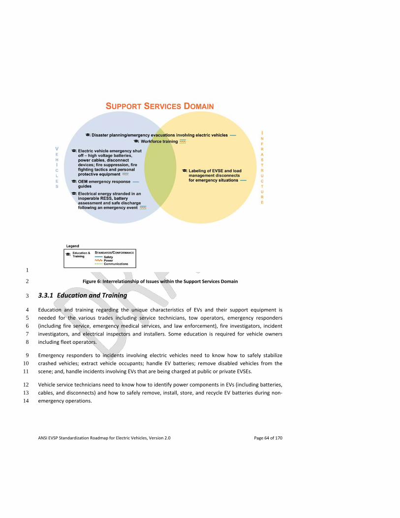
ANSI EVSP Standardization Roadmap for Electric Vehicles, Version 2.0 Page 64 of 170
1
Figure 6: Interrelationship of Issues within the Support Services Domain 2
3.3.1 Education and Training 3
Education and training regarding the unique characteristics of EVs and their support equipment is 4
needed for the various trades including service technicians, tow operators, emergency responders 5
(including fire service, emergency medical services, and law enforcement), fire investigators, incident 6
investigators, and electrical inspectors and installers. Some education is required for vehicle owners 7
including fleet operators. 8
Emergency responders to incidents involving electric vehicles need to know how to safely stabilize 9
crashed vehicles; extract vehicle occupants; handle EV batteries; remove disabled vehicles from the 10
scene; and, handle incidents involving EVs that are being charged at public or private EVSEs. 11
Vehicle service technicians need to know how to identify power components in EVs (including batteries, 12
cables, and disconnects) and how to safely remove, install, store, and recycle EV batteries during non‐13
emergency operations. 14
ANSI EVSP Standardization Roadmap for Electric Vehicles, Version 2.0 Page 65 of 170
Electricians and electrical inspectors need to know how to properly install EVSE and demonstrate to 1
building owners and homeowners how to operate EVSE and any associated load management 2
equipment. 3
Fleet operators and vehicle owners need to know how to charge their vehicles and how to properly 4
disable the EV power source to their vehicle once charging is completed. 5
3.3.1.1 Electric Vehicle Emergency Shut Off – High Voltage Batteries, Power Cables, Disconnect 6
Devices; Fire Suppression, Fire Fighting Tactics and Personal Protective Equipment 7
Emergency responders need to be able to quickly and easily identify high voltage EV batteries and 8
power cables, disable high voltage systems, and otherwise safely manage emergency events involving 9
electric vehicles. Clear safety markings and procedures on how to shut off power to an EV following an 10
incident would help to protect the safety of emergency responders, law enforcement, tow operators, 11
and vehicle occupants from electrical shock hazards during passenger extrication and post crash vehicle 12
movement and servicing. Best practices for fire suppression, fire fighting tactics and personal protective 13
equipment are also necessary to ensure safety. 14
3.3.1.2 Labeling of EVSE and Load Management Disconnects for Emergency Situations 15
General safety labeling of EVSE is important to protect those operating the equipment. In addition, 16
during emergencies involving EVs that are connected to charging stations, either in public or private 17
locations, emergency responders need to understand how to shut down and disconnect the equipment. 18
Labeling, especially graphics, would aid in quickly identifying devices and disconnect locations. 19
When EVSEs are used in conjunction with load management equipment, locations and connections to 20
the load management equipment should be easily identifiable and have ready access. In these cases, the 21
EVSE may be energized through a load management device which may measure other loads on a service 22
or feeder to determine whether there is adequate capacity to supply power to an EVSE. Another 23
configuration may permit the sharing of a 240‐volt branch circuit with another 240‐volt appliance 24
instead of being directly connected to a dedicated branch circuit with its own disconnecting means such 25
as a circuit breaker or fuse. The load management device in this configuration would only permit EVSE 26
operation when other loads are not present on the branch circuit. 27
3.3.1.3 OEM Emergency Response Guides 28
Vehicle manufacturers produce emergency response guides (ERGs) which provide instructions and 29
schematic details of safety procedures for their vehicles. These show access points, disconnect locations, 30
and chassis dismemberment locations valuable to first responders and rescuers particularly when 31
extrication of a vehicle passenger is required. 32
ANSI EVSP Standardization Roadmap for Electric Vehicles, Version 2.0 Page 66 of 170
3.3.1.4 Electrical Energy Stranded in an Inoperable RESS; Battery Assessment and Safe Discharge 1
Following an Emergency Event 2
A rechargeable energy storage system (RESS) is a completely functional electrical energy storage device 3
consisting of the battery pack(s) and the ancillary subsystems necessary for physical support, protection 4
and enclosure, thermal management, and control (including electronic control). The automotive 5
application of an RESS during normal operating conditions relies greatly on advanced electronic‐6
management systems to control the energy flow into the pack during charging and energy discharge 7
from the battery pack when needed for propulsion of the vehicle. 8
In most electrically propelled vehicles, during unintended or abnormal events (such as a vehicle crash), 9
vehicle safety systems, including high‐voltage electrical contactor switches are designed to open the 10
high‐voltage circuit, isolating the energy within the battery and placing the electrical propulsion system 11
in a non‐operative mode. These systems provide safety from electrical shock as required for compliance 12
with FMVSS No. 305, as well as unintended propulsion. However, current RESS design principles 13
governing the contactor safety device prevent the remaining energy in the pack from being accessed or 14
removed. In certain cases, this energy will be contained in an undamaged battery without incident, and 15
after proper diagnostic evaluation by trained personnel, the battery may be returned to operation at the 16
discretion of the OEM. 17
In other circumstances, when the RESS, including the high voltage battery, has been damaged, there is 18
an increased risk to responders and others from stranded energy. A damaged RESS may result in loss of 19
the ability to maintain thermal stability within the high voltage battery. The safety risks increase in 20
relation to the level of energy as measured by the battery pack’s state of charge (SOC). This combination 21
of a damaged RESS and high SOC can result in elevated potential safety risks, in the form of electric 22
shock and exothermic release of the stranded energy (venting, fire, or explosion), to the people handling 23
the vehicle and the battery pack, such as emergency first and second responders, repair technicians, or 24
battery recyclers. 25
In addition, it is generally assumed that at the end of battery life, if by age or premature damage, every 26
battery will have to be discharged for safety reasons before secondary use or recycling. 27
3.3.1.5 Disaster Planning / Emergency Evacuations Involving Electric Vehicles 28
A longer term issue that has been raised is disaster planning and the need for guidelines or standards to 29
deal with emergency evacuation situations especially those involving large numbers of electric vehicles 30
on the road at the same time. If traffic congestion caused a number of electric vehicles to become 31
depleted of charge on major evacuation routes (e.g., bridges and tunnels), this could become a serious 32
issue. 33

ANSI EVSP Standardization Roadmap for Electric Vehicles, Version 2.0 Page 67 of 170
3.3.1.6 Workforce Training 1
In addition to the training requirements described above, as the electric vehicle market grows and 2
creates jobs, there is an increasing need for widespread occupational training and education to support 3
the life cycle of EVs and associated infrastructure. 4
5

ANSI EVSP Standardization Roadmap for Electric Vehicles, Version 2.0 Page 68 of 170
1
2
3
4
5
6
7
[this page intentionally left blank] 8
ANSI EVSP Standardization Roadmap for Electric Vehicles, Version 2.0 Page 69 of 170
4. Gap Analysis of Standards, Codes, Regulations, 1
Conformance Programs and Harmonization Efforts 2
Section 4 presents the details of the gap analysis of standards, codes, regulations, and conformance 3
programs, be they existing or in development, with particular focus on those that are pertinent to the 4
rollout of electric vehicles in the United States. This assessment also included a review of relevant 5
harmonization activities underway. 6
In this context, a gap refers to a significant issue – whether it be related to safety, performance, 7
interoperability, etc. – that has been identified and that should be addressed in a standard, code, 8
regulation or conformance program but no standard, code, regulation or conformance program 9
currently is published or known to exist that adequately addresses the issue. Gaps can be filled through 10
the creation of entirely new standards, code provisions, regulation, or conformance programs, or 11
through revisions to existing ones. In some cases work may already be in progress to fill the gap. 12
A partial gap refers to a situation where a significant issue has been identified that is partially addressed 13
by an existing standard, code, regulation or conformance program. 14
No gap means there is no significant issue that has been identified at this time or that is not already 15
adequately covered by an existing standard, code, regulation or conformance program. 16
Note: If no information is provided in the sections that follow on conformance programs or 17
harmonization efforts, it means that either the issue was not addressed or no gap was identified at this 18
time with respect to the issue. 19
Additional details regarding the identified standards, codes, regulations, and conformance programs 20
described in this section can be found in the ANSI EVSP Roadmap Standards Compendium. 21
4.1 Vehicle Domain 22
Terminology 23
There are published standards devoted to general technical terms as well as published standards specific 24
to electric vehicle terminology. The goal should be to encourage the use of consistent terminology 25
related to electric vehicles. 26
- ISO 8713, Electric road vehicles – Vocabulary, published in 2012, establishes a vocabulary of 27
terms used in relation to electric road vehicles and focuses on terms specific to electric road 28
vehicles. 29
- SAE J1715, Hybrid Electric Vehicle (HEV) & Electric Vehicle (EV) Terminology, published in 2008, 30
is intended as a resource for those writing other electric vehicle documents, specifications, 31
standards, or recommended practices. SAE J1715 is in the process of being split into two parts 32
ANSI EVSP Standardization Roadmap for Electric Vehicles, Version 2.0 Page 70 of 170
among the SAE Hybrid Committee and SAE Battery Committee. The new standard will be 1
designated parts 1 and 2. 2
Partial Gap: Terminology. There is a need for consistency with respect to electric vehicle terminology. 3
Recommendation: Complete work to revise SAE J1715. Priority: Mid‐term. Potential Developer: SAE, 4
ISO. Grid Related: No. Status of Progress: Green. Update: SAE J1715 is still in revision and is targeted for 5
publication in the Spring of 2013. 6
4.1.1 Energy Storage Systems 7
4.1.1.1 Power Rating Methods 8
In version 1.0 of this roadmap, there was a statement that two standards are under development to 9
address power rating methods for electric vehicles: 10
- SAE J2907, Power rating method for automotive electric propulsion motor and power 11
electronics sub‐system, which provides a test method and conditions for rating the performance 12
of electric propulsion motors as used in hybrid electric and battery electric vehicles; and 13
- SAE J2908, Power rating method for hybrid‐electric and battery electric vehicle propulsion, 14
which provides a test method and conditions for rating performance of complete hybrid‐electric 15
and battery electric vehicle propulsion systems reflecting thermal and battery capabilities and 16
limitations. 17
Gap: Power rating methods. It was noted in roadmap version 1.0 that standards for electric vehicle 18
power rating methods are still in development. 19
Recommendation: Complete work to develop SAE J2907 and J2908. Priority: Mid‐term. Potential 20
Developer: SAE. Grid Related: No. Status of Progress: Red. Update: With respect to the roadmap 21
version 1.0 gap, work on the power rating method standards SAE J2907 and J2908 has been canceled 22
because of resource issues. It will be re‐opened under a new J number at a future date yet to be 23
determined. 24
4.1.1.2 Battery Safety 25
EV battery safety standards development has been identified as a priority by standards development 26
organizations including IEC, ISO, SAE and UL, the regulatory body NHTSA, and the inter‐governmental 27
body WP.29 via its EVS‐IWG. As a result, a number of electric vehicle battery and related safety 28
standards have been published or are currently under revision or development. A breakdown of this 29
effort by organization follows: 30
ANSI EVSP Standardization Roadmap for Electric Vehicles, Version 2.0 Page 71 of 170
IEC 1
- IEC 62660‐2, Secondary batteries for the propulsion of electric road vehicles – Part 2: Reliability 2
and abuse testing for lithium‐ion cells, was published in 2010. Although not specifically 3
identified as a safety standard, it does include tests which address safety issues such as short 4
circuit and overcharge. 5
ISO 6
- ISO 6469‐1, Electric road vehicles – Safety specifications – Part 1: On‐board rechargeable energy 7
storage system (RESS), published in 2009, provides general safety criteria to protect persons 8
within and outside of the vehicle and applies to batteries and other RESS. 9
- ISO 6469‐3, Electrically propelled road vehicles – Safety specification – Part 3: Protection of 10
persons against electric shock, published in 2011, addresses electrical safety of the RESS within 11
the overall vehicle. 12
- ISO 12405‐1, Electrically propelled road vehicles – Test specification for lithium‐ion traction 13
battery packs and systems – Part 1: High‐power applications, was published in 2011. It is 14
primarily focused on performance. However, it does contain tests that pertain to lithium‐ion 15
battery safety such as short circuit, overcharge, and over discharge tests. 16
- ISO 12405‐2, Electrically propelled road vehicles – Test specification for lithium‐ion traction 17
battery packs and systems – Part 2: High‐energy applications, was published in 2012. It is similar 18
to its Part 1 counterpart for high power applications and contains tests related to lithium‐ion 19
battery safety. 20
- ISO 12405‐3, Electrically propelled road vehicles – Test specification for lithium‐ion traction 21
battery packs and systems – Part 3: Safety. This standard, currently in development, will be the 22
ISO safety standard for lithium batteries for EV applications. 23
SAE 24
- SAE J1766, Recommended Practice for Electric and Hybrid Electric Vehicle Battery Systems Crash 25
Integrity Testing, was published in 2005 and is currently under revision. It specifically addresses 26
electric vehicle safety concerns resulting from a vehicle crash event. 27
- SAE J2464, Electric and Hybrid Electric Vehicle Rechargeable Energy Storage System (RESS) 28
Safety and Abuse Testing, revised in 2009, provides a series of tests with which to determine an 29
RESS response to a potential abuse condition. 30
- SAE J2929, Safety Standard for Electric and Hybrid Vehicle Propulsion Battery Systems Utilizing 31
Lithium‐based Rechargeable Cells, defines a minimum set of acceptable safety criteria for a 32
lithium‐based rechargeable battery system to be considered for use in a vehicle propulsion 33
ANSI EVSP Standardization Roadmap for Electric Vehicles, Version 2.0 Page 72 of 170
application as an energy storage system connected to a high voltage power train. A revision to 1
the standard was published in February 2013. 2
UL 3
- UL 2580, Batteries for Use in Electric Vehicles, was published as an Outline of Investigation in 4
2009, and as ANSI/UL 2580 in October 2011. This standard evaluates the cells, cell modules and 5
battery pack's ability to safely withstand simulated abuse conditions. The standard is non‐6
chemistry specific and includes construction requirements and tests to address safety of the 7
electric energy storage assembly and modules which can consist of batteries and/or 8
electrochemical capacitors. 9
NHTSA 10
- NHTSA FMVSS 305, Electric Powered Vehicles: Electrolyte spillage and electrical shock 11
protection. Last revised in 2011, it is a set of requirements intended to reduce deaths and 12
injuries during a crash, which occur because of electrolyte spillage from propulsion batteries, 13
intrusion of propulsion battery system components into the occupant compartment, and 14
electrical shock. 15
EVS‐IWG 16
As noted earlier, the EVS‐IWG under WP.29 is working to develop a Global Technical Regulation (GTR) 17
that would address potential safety risks of EVs while in use and after a crash event, including electrical 18
shocks associated with the high voltage circuits of EVs and potential hazards associated with lithium‐ion 19
batteries and/or other rechargeable energy storage systems (RESS) (in particular, containing flammable 20
electrolyte). The GTR will also set provisions and test protocols to ensure the vehicle system and/or 21
electrical components perform safely, are appropriately protected, and are electrically managed while 22
recharging from external electricity sources, whether at a residence or other charging location. 23
In 2012, the EVS‐IWG met twice, once in April and later in October, in Washington, DC and Bonn, 24
Germany, respectively. The Terms of Reference were approved at the 2nd meeting in Bonn. At the 2nd 25
meeting, the International Organization of Automobile Manufacturers (OICA) provided a detailed 26
presentation of its proposal for GTR consideration (much of which is based on adopting provisions 27
contained in UNECE‐R100, Uniform Provisions Concerning the Approval of Battery Electric Vehicles with 28
Regard to Specific Requirements for the Construction and Functional Safety). The OICA proposal focuses 29
on: 1) provisions for protection of electrical shock for in‐use and post‐crash, and 2) provisions to ensure 30
safety performance of RESS for in‐use and post‐crash. Further consideration of the OICA proposal will 31
continue in 2013. 32
With regard to the timelines for establishing the GTR, two options are being considered: 1) develop the 33
GTR in two phases, and 2) develop a complete and comprehensive GTR in a single phase. In Option 1, 34
Phase 1 would be based on the OICA proposal while Phase 2 would address RESS items that require 35
more research. Under Option 2, the IWG would attempt to address all issues in a single phase. 36
ANSI EVSP Standardization Roadmap for Electric Vehicles, Version 2.0 Page 73 of 170
As proposed by OICA, the GTR would apply to all vehicles of Category 1‐1 and 1‐2, with a gross vehicle 1
mass (GVM) of 4,536 kilograms or less, equipped with electric power train containing high voltage bus, 2
excluding vehicles permanently connected to the grid. Per the OICA proposal, the following vehicles 3
would be excluded: 4
a) A vehicle with four wheels whose unladed mass is not more than 350 kg, not including the mass 5
of the batteries in case of electric vehicles, whose maximum design speed is not more than 45 km/h, 6
and whose engine cylinder capacity does not exceed 50 cm3 for spark (positive) ignition engines, or 7
whose maximum net power output does not exceed 4 kW in the case of other internal combustion 8
engines, or whose maximum continuous rated power does not exceed 4 kW in the case of electric 9
engines. 10
and 11
b) A vehicle with four wheels, other than that classified under a) above, whose unladed mass is not 12
more than 400 kg, not including the mass of batteries in the case of electric vehicles and whose 13
maximum continuous rated power does not exceed 15 kW. 14
The EVS‐IWG held its third meeting in mid‐April in Tokyo, Japan and a fourth meeting is tentatively 15
scheduled for October 2013 in Beijing, China. 16
* * * 17
Although there has been active work in the battery safety standards area, the committee identified two 18
gaps that need to be addressed. 19
Functional safety in the charging system 20
With funding from the U.S. Department of Transportation (DOT) and NHTSA, SAE International has 21
undertaken a Cooperative Research Project (CRP) to Develop Repeatable Safety Performance Test 22
Procedures for Rechargeable Energy Storage Systems (RESS), in partnership with five major automotive 23
original equipment manufacturers (OEMs) actively working on RESS. This research will include 24
investigation of failure modes and the results will be considered by NHTSA in connection with future 25
rulemaking (e.g., this could be a functional safety standard, FMVSS for battery system safety, or a 26
proposal for a GTR). SAE TEVVBC1 also plans to integrate the results of this research into future revisions 27
of SAE J2929. The CRP report is targeted for release in October 2013. 28
Gap: Functional safety in the charging system. Potential faults in the charging system, both on‐board 29
and off‐board, are the subject of NHTSA sponsored research and may need to be addressed in future 30
rulemaking and/or standardization. 31
Recommendation: Future NHTSA rulemaking and/or revisions to SAE J2929 should consider the results 32
of the DOT/NHTSA‐funded SAE Cooperative Research Project with respect to fault events in the charging 33
system which could lead to overcharging. Priority: Near‐term. Potential Developer: NHTSA, SAE. Grid 34
Related: No. Status of Progress: Green. Update: The roadmap version 1.0 gap statement and 35
ANSI EVSP Standardization Roadmap for Electric Vehicles, Version 2.0 Page 74 of 170
recommendation have been updated to note NHTSA‐funded research, that the issue may be with the 1
charging system rather than the battery, and that NHTSA rulemaking may result. NHTSA has been added 2
as a potential developer and the priority level has been changed from mid‐term to near‐term. Recent 3
updates to SAE J2929 do not address charging system failure; rather, they relate to electromagnetic 4
compatibility (EMC) to ensure the safety functions of the battery are not impacted. 5
Delayed battery overheating events 6
All of the current tested failure modes of battery systems can be classed as “real time” with regard to 7
outcome. If a European Council for Automotive R&D (EUCAR) hazard level of greater than 2 happens – 8
the EUCAR rating system is used in SAE J2464 – it is assumed that it happens within minutes or a few 9
hours at most. It is now known that some faults that can create EUCAR 2 or higher events may not 10
surface for days or even weeks. This possibility introduces a new hazard potential that could surface at 11
any time unless expediently dealt with in a safe manner. Some of these scenarios are easily recognized 12
and dealt with such as in vehicle accidents and with faulty chargers or battery management systems. 13
Scenarios that are less obvious or detectable are internal partial pack circulating currents that escalate 14
over time to dangerous thermal states. Stray currents occurring in sub sections of a pack that are 15
intermediate in value between zero and hard shorts can evolve and generate excessive temperatures. 16
Gap: Delayed battery overheating events. The issue of delayed battery overheating needs to be 17
addressed. 18
Recommendation: Address the issue of delayed battery overheating events in future rulemaking and/or 19
revisions of SAE J2929 based on the results of the DOT/NHTSA‐funded SAE Cooperative Research 20
Project. Priority: Near‐term. Potential Developer: NHTSA, SAE. Grid Related: No. Status of Progress: 21
Yellow. Update: The roadmap version 1.0 recommendation has been updated to note NHTSA‐funded 22
research which may result in future rulemaking. NHTSA has been added as a potential developer. 23
Version 2 of SAE J2929 has been published. However, the topic of delayed battery overheating events is 24
not addressed in this revision; it is pending the results of the NHTSA sponsored research. 25
4.1.1.3 Battery Testing – Performance and Durability 26
The principal areas of interest relating to standards for battery performance and durability testing are as 27
follows: 28
Cell level performance testing: Specifically in the IEC realm, there are multiple standards for defining and 29
measuring common performance characteristics, with emphasis on the loading conditions expected in 30
electric vehicle or hybrid electric vehicle applications. 31
Pack level performance testing: Specifically, in the ISO 12405‐1 and 12405‐2 standards, attention is given 32
to the distinction between high energy and high power applications. These also attempt to define and 33
measure common performance characteristics based on EV or HEV applications. 34
ANSI EVSP Standardization Roadmap for Electric Vehicles, Version 2.0 Page 75 of 170
There is a need to focus on harmonization of key battery performance parameters for electric vehicle 1
applications. For example: “12kWh capacity” alone does not provide sufficient information due to 2
varying methods of measuring and calculating battery capacities. This is particularly key at the cell level, 3
as the cells are the primary determination to battery charge/discharge currents and capacities. 4
Durability and environmental endurance requirements: Some work has been done to define life‐cycle 5
testing parameters under simulated environmental conditions. However, for environmental test 6
conditions, reliance appears to be on existing generic automotive or electronics testing requirements, 7
which will require further modification for battery applications. 8
Environmental durability test requirements (e.g., temperature, humidity, vibration, etc.) could also be 9
better defined, as current practices are to adapt existing automotive electronics requirements to the 10
battery and battery management system on a case‐by‐case basis. 11
SAE is revising J1798, Recommended Practice for Performance Rating of Electric Vehicle Battery 12
Modules, published in 2008, which provides for common test and verification methods to determine 13
electric vehicle battery module performance. 14
In addition, UL has defined requirements and testing and certification services for batteries. 15
Gap: Battery performance parameters and durability testing. There is a need for further work on EV 16
battery performance parameters and environmental durability test requirements. 17
Recommendation: Complete work on SAE J1798 and if possible consider harmonization with ISO 12405‐18
2. Priority: Mid‐term. Potential Developer: SAE, ISO. Grid Related: No. Status of Progress: Yellow. 19
Update: There is not a lot of progress to date on SAE J1798. 20
4.1.1.4 Battery Storage, Packaging, Transport and Handling 21
Battery Storage 22
The following standards, code provisions and regulations relate to safety aspects of battery storage: 23
- IEC 60068, Environmental testing. Part 1: General and guidance, provides guidance regarding 24
testing of equipment such as batteries under different environmental conditions, which it 25
expects to be exposed to during storage and operations. 26
- ICC publishes the International Fire Code® (IFC®). 27
- NFPA 1, Fire Code, Chapter 52 covers stationary battery installations, which would come into 28
play where batteries are used in a fixed energy storage facility. 29
- NFPA 13, Standard on Installation of Sprinkler Systems, addresses fire protection of storage 30
occupancies. This document’s technical committee is working on requirements for handling and 31
storing EV batteries based on the results of the National Fire Protection Research Foundation 32
report on lithium‐ion batteries. 33
ANSI EVSP Standardization Roadmap for Electric Vehicles, Version 2.0 Page 76 of 170
- NFPA 30A, Standard for Motor Fuel Dispensing Facilities and Repair Garages, covers fire 1
protection requirements for fueling and service stations including service garages. This 2
committee is also looking at requirements for safe handling of EV batteries at these locations. 3
- NFPA 70®, the National Electrical Code®, Article 480, Storage Batteries, 2011, covers the 4
installation of electrical conductors, equipment, and raceways; signaling and communications 5
conductors, equipment, and raceways; and optical fiber cables and raceways. 6
- SAE J2950, Recommended Practices (RP) for Transportation and Handling of Automotive‐type 7
Rechargeable Energy Storage Systems (RESS). This standard addresses identification, handling, 8
and shipping of un‐installed RESSs to/from specified locations (types) required for the 9
appropriate disposition of new and used items. 10
- OSHA 1910, storage batteries, where provisions shall be made for sufficient diffusion and 11
ventilation of gases from storage batteries to prevent the accumulation of explosive mixtures. 12
- IEC 62840, Electric Vehicle Battery Exchange Infrastructure Safety Requirements, is a new work 13
item within IEC/TC 69 that encompasses storage of lithium‐ion batteries. 14
- NFPA’s Fire Protection Research Foundation has also started a research project looking at fire 15
suppression techniques related to burning of EV batteries. 16
Gap: Safe storage of lithium‐ion batteries. At present, there are no published standards addressing the 17
safe storage of lithium‐ion batteries specifically, whether at warehouses, repair garages, recovered 18
vehicle storage lots, auto salvage yards, or battery exchange locations. 19
Recommendation: A standard on safe storage practices for EV batteries must be developed, addressing 20
both new and waste batteries and the wide range of storage situations that may exist, including when 21
the batteries are separated from their host vehicle. Priority: Near‐term. Potential Developer: SAE, NFPA, 22
ICC, IEC/TC 69. Grid Related: No. Status of Progress: Green. Update: Roadmap version 1.0 gap 23
statement has been modified to say there are no published standards addressing safe storage. IEC 62840 24
and the research project of the NFPA’s Fire Protection Research Foundation are noted in the text. 25
Battery Packaging, Transport and Handling 26
So far, only limited standards work has been done in this area including: 27
- SAE J1797, Recommended Practice for Packaging of Electric Vehicle Battery Modules, published 28
in 2008. This Recommended Practice provides for common battery designs through the 29
description of dimensions, termination, retention, venting system, and other features required 30
in an electric vehicle application. 31
- As noted above, there is also SAE J2950, Recommended Practices (RP) for Transportation and 32
Handling of Automotive‐type Rechargeable Energy Storage Systems (RESS). 33
ANSI EVSP Standardization Roadmap for Electric Vehicles, Version 2.0 Page 77 of 170
- ISO/IEC PAS 16898, Electrically propelled road vehicles – Dimensions and designation of 1
secondary lithium‐ ion cells, was published in 2012 and a revision is targeted for publication in 2
2013. 3
At the end of 2010, the United Nations (UN) specifically classified lithium‐ion batteries as part of its 4
amendments to the model regulations on the transport of dangerous goods. Thus, transportation of 5
new batteries is now covered by the International Air Transport Association (IATA), International Civil 6
Aviation Organization (ICAO), International Maritime Organization (IMO), and local transportation 7
regulations in countries of import/export, based on the appropriate UN number: 8
- 3090, Lithium Metal Batteries (including lithium alloy batteries); 9
- 3091, Lithium Metal Batteries Contained In Equipment (including lithium alloy batteries) or 10
Lithium Metal Batteries Packed With Equipment (including lithium alloy batteries); 11
- 3480, Lithium‐ion Batteries (including lithium‐ion polymer batteries); and 12
- 3481, Lithium‐ion Batteries Contained In Equipment (including lithium‐ion polymer batteries) or 13
Lithium‐ion Batteries Packed With Equipment (including lithium‐ion polymer batteries). 14
UN recommendations (Manual of Tests and Criteria, section 38) also cover packaging limitations to 15
ensure proper containment against pressure and temperature changes, mechanical drops etc. 16
The Portable Rechargeable Battery Association (PRBA) and the International Association for the 17
Promotion and Management of Portable Rechargeable Batteries (RECHARGE) submitted a joint proposal 18
on this issue to the UN Subcommittee of Experts (UN SCOE) on the Transport of Dangerous Goods. The 19
proposal was discussed at the Subcommittee’s June /July 2012 meeting, the result of which was that the 20
groups were invited to submit a new proposal. 21
Gap: Packaging and transport of waste batteries. Current standards and regulations do not adequately 22
cover transportation aspects of waste batteries (damaged, aged, sent for repair, end‐of‐life) in terms of 23
packaging, loading limitations, combination with other dangerous goods on same transport, etc. 24
Recommendation: There is a need for a harmonized approach toward communication, labeling, 25
packaging restrictions, and criteria for determining when a battery is waste. Priority: Near‐term. 26
Potential Developer: UN SCOE on the Transport of Dangerous Goods, ISO/TC 22/SC21, SAE or UL. Grid 27
Related: No. Status of Progress: Green. Update: The UN SCOE was added as a potential developer as 28
there is a proposal before it. 29
30
Gap: Packaging and transport of batteries to workshops or battery swapping stations. Unloading a 31
battery in a battery swapping station is extremely challenging with the original packaging used for 32
dangerous goods transportation. There is a need for standards for intermediate packaging to cover 33
transport to battery swapping stations. 34
ANSI EVSP Standardization Roadmap for Electric Vehicles, Version 2.0 Page 78 of 170
Recommendation: Intermediate packaging is required between the import location of the battery and 1
battery swapping stations and needs to be standardized around geometry, safety and matching to UN 2
packaging requirements. Priority: Mid‐term. Potential Developer: ISO/TC 22/SC21, IEC/TC 69, SAE or UL. 3
Grid Related: No. Status of Progress: Not started. 4
4.1.1.5 Battery Recycling 5
The following documents are directed at all battery types including Lithium batteries: 6
- SAE J2974, Technical Information Report on Automotive Battery Recycling. In development and 7
targeted for publication by the end of 2013, this document provides a compilation of current 8
recycling definitions, technologies and flow sheets and their application to different battery 9
chemistries. 10
- SAE J2984, Identification of Transportation Battery Systems for Recycling Recommended 11
Practice. Published in June 2012 with a revision targeted for the Spring of 2013, this document 12
includes a chemistry identification system intended to support the proper and efficient recycling 13
of rechargeable battery systems used in transportation applications with a maximum voltage 14
greater than 12V (including SLI batteries). 15
In terms of regulations, lithium‐ion battery recycling compliance requirements are limited to a few 16
states in the U.S., including California, Oregon and Florida. The lack of harmonization and clear battery 17
producer responsibility (in contrast to requirements in Europe for example) may potentially limit the 18
battery recycling schemes in the U.S. Nevertheless, federal grants are given as an incentive to develop 19
these recycling technologies and meet the demands of eMobility in the U.S. 20
Gap: Battery recycling. Standards are needed in relation to EV (li‐ion) battery recycling. 21
Recommendation: Complete work on SAE J2974 and J2984. EV (li‐ion) battery recycling standards are 22
desirable to address the calculation method toward recycling efficiency and recovery rates based on an 23
agreed unit (possibly weight) and/or life‐cycle assessment tools, including energy recovery. Priority: 24
Near‐term. Potential Developer: SAE, IEC. Grid Related: No. Status of Progress: Green. Update: The 25
roadmap version 1.0 text and recommendation have been updated to note relevant work by SAE. The 26
priority level has been changed from long‐term to near‐term. 27
4.1.1.6 Battery Secondary Uses 28
SAE TEVVBC15, Secondary Battery Use Committee, is tasked with developing standards to address 29
battery second life applications and has begun initial investigation of this topic. Most OEMs predict a 70‐30
80% capacity remaining in the lithium‐ion battery after automotive initial purpose. Assuming the 31
replacement pack is returned to an authorized dealer or support facility, a simple test or state of health 32
record can assess the next steps. SAE J2950 can be used to safely ship batteries for storage or 33
repackaging for alternative uses. SAE J2936 can be used to correctly label the battery for handling. 34
Logistics will be required to facilitate different battery chemistries, various sizes and matching. Battery 35
ANSI EVSP Standardization Roadmap for Electric Vehicles, Version 2.0 Page 79 of 170
management systems should be utilized as needed to maintain safety. Appropriate packaging methods 1
are also needed to avoid abuse. 2
Gap: Battery secondary uses. There is a need for standards to address battery second life applications 3
for grid storage and other uses. 4
Recommendation: Explore the development of standards for battery secondary uses, addressing such 5
issues as safety and performance testing for intended applications, grid connection/communication 6
interfaces, identification of parts/components that can be removed from the pack without destroying it, 7
etc. Priority: Mid‐term. Potential Developer: SAE, UL. Grid Related: No. Status of Progress: Green. 8
Update: The text has been updated to note some of the considerations in the work thus far by the SAE 9
committee. The priority level has been changed from long‐term to mid‐term. UL has been added as a 10
potential developer. 11
4.1.1.7 Crash Tests / Safety 12
FMVSS 305 13
The only federal motor vehicle safety standard that is unique to electric vehicles is FMVSS 305, Electric‐14
Powered Vehicles: Electrolyte Spillage and Electrical Shock Protection. In 2010, FMVSS 305 was updated 15
so as to align it more closely with the April 2005 version of SAE J1766, Recommended Practice for 16
Electric and Hybrid Electric Vehicle Battery Systems Crash Integrity Testing. In July 2011, the standard 17
was again amended in response to petitions for reconsideration filed subsequent to the publication of 18
the 2010 final rule. As amended, FMVSS 305 is intended to provide manufacturers greater flexibility, 19
requiring them to design electrically‐powered vehicles so that, in the event of a crash, the electrical 20
energy storage, conversion, and traction systems are either electrically isolated from the vehicle’s 21
chassis or their voltage is below specified levels considered safe from electric shock hazards. 22
Since the physiological impacts of direct current (DC) are less than those of alternating current (AC), the 23
standard specifies lower electrical isolation requirements for certain DC components (100 ohms/volt) 24
than for AC components (500 ohms/volt). The recent rulemakings resulted in the introduction of new 25
definitions, changes to existing definitions, changes to the energy storage/conversion device retention 26
requirements, the introduction of a low voltage option for achieving electrical safety, and a requirement 27
for monitoring of the isolation resistance of DC high voltage sources that comply with the 100 ohms/volt 28
electrical isolation requirement. As amended, FMVSS 305 applies to passenger cars, multi‐purpose 29
vehicles (MPVs), trucks and buses that have a gross vehicle weight rating (GVWR) of 4,536 kg or less, 30
that use electrical components with working voltages more than 60 volts direct current (VDC) or 30 volts 31
alternating current (VAC), and whose speed attainable over a distance of 1.6 km on a paved level surface 32
is more than 40 km/h. This differs from the previously‐existing standard that similarly applied to 33
passenger cars, MPVs, trucks and buses that have a GVWR of 4,536 kg or less but that was limited to 34
vehicles that use more than 48 nominal volts of electricity as propulsion power and whose speed 35
attainable in 1.6 km on a paved level surface is more than 40 km/h. 36
37
ANSI EVSP Standardization Roadmap for Electric Vehicles, Version 2.0 Page 80 of 170
SAE EV Crash Test Safety Procedures Task Force 1
SAE has formed an EV Crash Test Safety Procedures Task Force under the Impact and Rollover Test 2
Procedures Standards Committee. The scope of the task force is to create and maintain information 3
reports and recommended practices that relate to laboratory and personnel safety when conducting 4
dynamic crash testing of EVs. Published work shall reflect the current industry “best practices” for 5
testing and provide a basis for industry harmonization of these methods, to the extent possible. There is 6
an understanding that these methods will change over time. Laboratory tasks being looked at include 7
vehicle receiving and inspection, vehicle preparation, crash tests, post‐crash inspection, and post‐crash 8
storage. The documents will address battery system failures due to electrical and mechanical abuse, 9
personal protective equipment, training, emergency procedures, thermal runaway risk, toxic emissions, 10
and other battery health assessments. The group hopes to publish an information report by the Spring 11
of 2013. 12
As noted earlier, NFPA’s Fire Protection Research Foundation has also started a research project looking 13
at similar questions related to burning of EV batteries and recommendations for suppression efforts. 14
SAE J2929 has added a section on rollover, but this will not cover all the issues that this task force is 15
exploring. 16
No gaps have been identified at this time with respect to this issue. 17
4.1.2 Vehicle Components 18
4.1.2.1 Internal High Voltage Cables, On‐Board Wiring, Component Ratings and Charging 19
Accessories 20
EV‐specific standards related to this topic include: 21
- IEC/TR 60783, Wiring and Connectors for Electric Road Vehicles, which applies to cabling and 22
connectors used in battery electric road vehicles. These recommendations are not applicable to 23
the low tension wiring (e.g. 12 V) for the auxiliary and signaling accessories, such as horn, 24
lighting, signaling lamps, wipers, etc., nor do they apply to connections between cells of the 25
traction battery. Rather, this document provides general rules for all external wiring and 26
connectors which are used for interconnecting the traction components and sub‐systems. The 27
rules are applicable to the heavy current, the light current, and the signal harnesses. Currently, 28
this publication has the status of a technical report, hence the “TR” designation. 29
- SAE J2894/1, Power Quality Requirements for Plug In Electric Vehicle Chargers. The intent of this 30
published document is to develop a recommended practice for PEV chargers, whether on‐board 31
or off‐board the vehicle, that will enable equipment manufacturers, vehicle manufacturers, 32
electric utilities and others to make reasonable design decisions regarding power quality. The 33
three main purposes are: 1) To identify those parameters of a PEV battery charger that must be 34
controlled in order to preserve the quality of the AC service; 2) To identify those characteristics 35
ANSI EVSP Standardization Roadmap for Electric Vehicles, Version 2.0 Page 81 of 170
of the AC service that may significantly impact the performance of the charger; and, 3) To 1
identify values for power quality, susceptibility and power control parameters which are based 2
on current U.S. and international standards. These values should be technically feasible and cost 3
effective to implement into PEV battery chargers. 4
- SAE J2894/2, Power Quality Requirements for Plug In Electric Vehicle Chargers ‐ Test Methods. 5
This standard, still in development, describes the test methods for the 6
parameters/requirements in SAE J2894/1. It addresses automatic charger restarts after a 7
sustained power outage, as well as the ability to ride through momentary outages. 8
- UL 62, Flexible Cords and Cables, which covers electric vehicle cable constructed as described in, 9
and listed for use in accordance with, Article 400 of NFPA 70®, the National Electrical Code®. The 10
cable is used to supply power, signal, and control to electric vehicles during the charging 11
process. Electric vehicle cable consists of two or more insulated conductors, with or without 12
grounding conductors, with an overall jacket. 13
- UL 458A, Power Converters/Inverters for Electric Land Vehicles, which covers power converters 14
and power inverters intended for use in electric vehicles. This category covers fixed and 15
stationary power converters, and accessories having a nominal rating of 600 V or less, direct or 16
alternating current. This category also covers fixed, stationary and portable power inverters 17
having a DC input and a 120 or 240 V AC output. These converters/inverters are intended for use 18
within electric land vehicles where not directly exposed to outdoor conditions. This category 19
also covers converters/inverters that are additionally intended to charge batteries. 20
- UL 2202, Electric Vehicle Charging System Equipment, which covers charging system equipment, 21
either conductive or inductive, intended for use with electric vehicles. The equipment can be 22
located on‐ or off‐board the vehicle. 23
- UL 2733, Surface Vehicle On‐Board Cable, which covers single‐conductor or single, coaxial cable 24
intended for the connection of components in an electric vehicle. The cable is rated 60, 75, 90 or 25
105°C (140, 167, 194 or 221°F), 300 or 600 V AC or DC, ‐30°C (‐22°F), oil resistant, water 26
resistant, and suitable for exposure to battery acid. 27
- UL 2734, Connectors for Use in On‐board Electric Vehicle Charging Systems, which covers 28
component connectors intended to interconnect both communication and power‐circuit 29
conductors rated up to 30 A and up to 600 V AC or DC within an on‐board electric vehicle 30
charging system. 31
General standards that may be applicable in the EV components environment include: 32
- IEC 61316, Industrial cable reels, which applies to cable reels with a rated operating voltage not 33
exceeding 690 V AC/DC and 500 Hz with a rated current not exceeding 63A, primarily intended 34
for industrial use, either indoors or outdoors, for use with accessories complying with IEC 35
60309‐1. 36
ANSI EVSP Standardization Roadmap for Electric Vehicles, Version 2.0 Page 82 of 170
- SAE J1654, High Voltage Primary Cable. This SAE Standard covers cable intended for use at a 1
nominal system voltage up to 600 VDC or 600 VAC. It is intended for use in surface vehicle 2
electrical systems. 3
- SAE J1673, High Voltage Automotive Wiring Assembly Design. This SAE Recommended Practice 4
covers the design and application of primary on‐board wiring distribution system harness to 5
road vehicles. This document applies to any wiring systems which contains one or more circuits 6
operating between 50V DC or AC RMS and 600 V DC or AC RMS excluding automotive ignition 7
cable. 8
- SAE J1742, Connections for High Voltage On‐Board Road Vehicle Electrical Wiring Harnesses ‐ 9
Test Methods and General Performance Requirements. Procedures included within this 10
specification are intended to cover performance testing at all phases of development, 11
production, and field analysis of electrical terminals, connectors, and components that 12
constitute the electrical connection systems in high power road vehicle applications that 13
operate at either 20 V to 600 volts regardless of the current applied, or any current greater than 14
or equal to 80 A regardless of the voltage applied. These procedures are applicable only to 15
terminals used for In‐Line, Header, and Device Connectors and for cable sizes up to 120 mm2 16
(4/0). 17
- UL 1004‐1, Traction Motors, which covers motors intended as the prime mover and installed in 18
or on vehicles for highway use, such as passenger automobiles, buses, trucks, vans, bicycles, 19
motorcycles and the like. These motors have been investigated for construction and operation 20
at rated output. They have additionally been investigated for the severity and profile of shock 21
and vibration likely to be encountered by motors mounted in road vehicles. 22
- USCAR‐37, High Voltage Connector Performance Supplement to SAE/USCAR‐2. Procedures 23
included within this specification supplement are, when used in conjunction with SAE/USCAR 2, 24
intended to cover performance testing at all phases of development, production, and field 25
analysis of electrical terminals, connectors, and components that constitute the electrical 26
connection systems in high voltage (60~600V) road vehicle applications. These procedures are 27
applicable to terminals used for In‐Line, Header, and Device Connector systems with and 28
without Shorting Bars. 29
In Europe and in other countries around the world, electric vehicles and on‐board components are 30
subject to review through both European and UN regulations. These regulations include European 31
Regulations 2007/46/EC or 2002/24/EC and the UNECE Regulations R100. UNECE R100 is the UN 32
Regulation which tests specific requirements for the construction, functional safety and hydrogen 33
emissions of battery‐powered all electric vehicles. UNECE R100 is required by many countries before an 34
electric vehicle can be road registered, and is also required before European Community Whole Vehicle 35
Type Approval (ECWVTA) can be issued. Safety Regulations and requirements within UNECE R100 36
include: vehicle constructional requirements (e.g., prevention of gas accumulation and correctly rated 37
circuit breakers); protection against electric shock through the assessment of covers and enclosures 38
ANSI EVSP Standardization Roadmap for Electric Vehicles, Version 2.0 Page 83 of 170
associated with high voltage components; assessment of access to high voltage components according 1
to protection degrees, etc. 2
In the U.S., FMVSS 305, Electric‐powered vehicles: electrolyte spillage and electrical shock protection, is 3
similar to R100 in Europe. In addition, all motor vehicles and items of motor vehicle equipment are 4
covered by the Motor Vehicles Safety Act in the U.S., meaning they are covered by NHTSA’s recall and 5
remedy provisions in the event there exists a safety‐related defect. 6
No gaps have been identified at this time with respect to this issue. 7
4.1.2.2 Vehicle Diagnostics – Emissions 8
In 1993, pursuant to Clean Air Act, the U.S. Environmental Protection Agency (EPA) published a final 9
rulemaking requiring manufacturers of light‐duty vehicles and light‐duty trucks to install on‐board 10
diagnostic (OBD) systems on such vehicles beginning with the 1994 model year. The regulations 11
promulgated in that final rule require manufacturers to install OBD systems which monitor emission 12
control components for any malfunction or deterioration causing exceedance of certain emission 13
thresholds, and which alert the vehicle operator to the need for repair. That rulemaking also requires 14
that, when a malfunction occurs, diagnostic information must be stored in the vehicle's computer to 15
assist the technician in diagnosis and repair. 16
Since the inception of the program, vehicle manufacturers have been allowed to satisfy federal OBD 17
requirements by installing OBD systems satisfying the OBD II requirements promulgated by the 18
California Air Resources Board (CARB). 19
Because hybrid electric vehicles and plug‐in hybrid electric vehicles are equipped with conventional 20
internal combustion or diesel engines, they comply with CARB and EPA OBD requirements. In some 21
cases, there are special OBD requirements that are specific to these hybrid and plug‐in hybrid electric 22
vehicles. 23
CARB’s OBD II rules can be found at: 24
- Title 13, California Code Regulations, Section 1968.2, Malfunction and Diagnostic System 25
Requirements for 2004 and Subsequent Model‐Year Passenger Cars, Light‐Duty Trucks, and 26
Medium‐Duty Vehicles and Engines (OBD II); and 27
- Title 13, California Code of Regulations, Section 1968.5, Enforcement of Malfunction and 28
Diagnostic System Requirements for 2004 and Subsequent Model‐Year Passenger Cars, Light‐29
Duty Trucks, and Medium‐Duty Vehicles and Engines. 30
For copies, see http://www.arb.ca.gov/msprog/obdprog/obdregs.htm. 31
Note: In December 2011, CARB proposed amendments to its OBD II regulation which, among other 32
things, would clarify how certain requirements are to be applied to hybrid and plug‐in hybrid electric 33
ANSI EVSP Standardization Roadmap for Electric Vehicles, Version 2.0 Page 84 of 170
vehicles. The proposed amendments were adopted by the Board at a hearing held in January 2012. A 1
copy of the regulation as amended is available at: 2
http://www.arb.ca.gov/msprog/levprog/leviii/leviii.htm. 3
No gaps have been identified at this time with respect to this issue. 4
4.1.2.3 Audible Warning Systems 5
Numerous activities are underway to address the concern that electric and some hybrid electric vehicles 6
may not be audibly detectable by the blind. These include NHTSA rulemaking (stemming from the 7
Pedestrian Safety Enhancement Act of 2010), Japanese and UNECE guidelines requiring EVs and HEVs to 8
generate a pedestrian alert sound, SAE and ISO technology neutral procedures for measuring vehicle 9
sound at low speeds, and the previously noted WP.29 effort to develop a Global Technical Regulation 10
(GTR). 11
In accordance with the Pedestrian Safety Enhancement Act of 2010, electric and hybrid electric vehicles 12
must emit an alert sound that allows blind and other pedestrians to reasonably detect a nearby electric 13
or hybrid vehicle operating below a certain cross‐over speed. The alert sound must be in compliance 14
with a new safety standard that NHTSA is required to create in accordance with the law. The NHTSA 15
notice of proposed rulemaking was published in the Federal Register on 14 January 2013 with comments 16
due by 15 March 2013. The law requires NHTSA to finalize the new standard by 4 January 2014. Under 17
the law, the new standard is required to be in effect within 36 months of publication of the final rule. 18
NHTSA has proposed to incorporate by reference portions of SAE J2889‐1, Measurement of Minimum 19
Noise Emitted by Road Vehicles, which was published in September 2011. At the request of NHTSA, SAE 20
issued a revised version of J2889/1 in May of 2012 to include metrics and measurement procedures for 21
changes to pitch and volume for innate and synthetic vehicle sounds. The SAE work product is the basis 22
for ISO 16254, an identical sound measurement standard in development. 23
Outside the U.S., electric and hybrid electric vehicles are being designed to comply with voluntary 24
guidelines. The Japanese Ministry of Land, Infrastructure, Transport and Tourism (MLIT) has voluntary 25
guidelines which require that EVs and HEVs generate a pedestrian alert sound whenever the vehicle is 26
moving forward at any speed less than 20 km/h and when the vehicle is operating in reverse. MLIT 27
guidelines do not require vehicles to produce an alert sound when the vehicle is operating, but stopped, 28
such as at a traffic light. The manufacturer is allowed to equip the vehicles with a switch to deactivate 29
the alert sound temporarily. In Europe, the UNECE has adopted guidelines covering alert sounds for EVs 30
and HEVs that are closely based on the Japanese guidelines. The guidelines will be published as an annex 31
to the UNECE Consolidated Resolution on the Construction of Vehicles (R.E.3). 32
The WP.29 work on a GTR is currently ongoing and will likely continue in parallel with the NHTSA 33
rulemaking activity which is ongoing. 34
35
ANSI EVSP Standardization Roadmap for Electric Vehicles, Version 2.0 Page 85 of 170
Partial Gap: Audible warning systems. Creation of the NHTSA safety standard and compliance with it 1
will effectively close any gap with respect to audible warning systems for electric vehicles sold in the U.S. 2
market. Ongoing standards work in SAE and ISO, and in WP.29 with respect to the development of a 3
Global Technical Regulation would provide a means for international harmonization around this issue. 4
Recommendation: Continue work on safety standards to address EV sound emission and measurement. 5
Priority: Near‐term. Potential Developer: SAE, ISO, NHTSA, WP.29. Grid Related: No. Status of Progress: 6
Green. 7
4.1.3 Vehicle User Interface 8
4.1.3.1 Graphical Symbols 9
There are several international standards and guidelines relating to graphical symbols and how to 10
develop them. These are general in nature and not specific to electric vehicles, but may be utilized by 11
standards development groups to develop a set of electric vehicle graphical symbols standards. There 12
are also some publications that relate specifically to markings on electrical equipment and 13
instrumentation for electric vehicles. These include: 14
- IEC 60445, Basic and safety principles for man‐machine interface, marking and identification ‐ 15
Identification of equipment terminals, conductor terminations and conductors, published in 16
2010, which contains rules for markings of electrical equipment including colors for conductors. 17
- IEC TR 60784, Instrumentation for electric road vehicles, published in 1984, provides high level 18
guidance on information that should be provided to the driver regarding operating and other 19
states of an electric vehicle battery. 20
PEVs include indicators on battery state of charge, if there is a system failure, etc. but these vary by 21
OEM. There is an SAE committee working on an “electronic fuel gauge” document that is waiting for 22
additional input from committee members on the direction of future work. 23
In terms of Federal Motor Vehicle Safety Standards and Regulations, there is: 24
- NHTSA FMVSS 101, Controls and Displays, most recently published in 2009, which provides 25
performance requirements for the location, identification, color, and illumination of motor 26
vehicle controls, telltales and indicators. It is not electric vehicle specific. 27
As described earlier, a DOT/NHTSA‐funded SAE Cooperative Research Project is looking at functional 28
safety studies and failure modes. Once these issues are better understood, it is possible that future 29
rulemaking could explore having a consistent symbol for high voltage failures. 30
Gap: Graphical symbols for electric vehicles. Standards for graphical symbols for electric vehicles are 31
needed to communicate important information to the driver such as state of charge, failure or normal 32
system operation which can be understood regardless of the driver’s language. 33
ANSI EVSP Standardization Roadmap for Electric Vehicles, Version 2.0 Page 86 of 170
Recommendation: Develop EV graphical symbols standards to communicate information to the driver. 1
Priority: Long‐term. Potential Developer: SAE, NHTSA, ISO, IEC. Grid Related: No. Status of Progress: 2
Not started. Update: The text has been updated to note NHTSA sponsored research on functional safety 3
and failure modes. The roadmap version 1.0 gap statement and recommendation have been re‐focused 4
on communication of information to the driver. NHTSA has been added as a developer and the priority 5
level has been changed to long‐term. Regarding the roadmap version 1.0 gap statement and 6
recommendation relating to graphical symbols for “parts under the hood,” this aspect is addressed in 7
section 4.3.1.1 on EV emergency shut off. 8
4.1.3.2 Telematics – Driver Distraction 9
The following are relevant with respect to conventional vehicles and are not specific to EVs: 10
- Auto Alliance Driver Focus Telematics Guidelines. This guideline provides 24 design principles for 11
telematics systems human‐machine interaction design to minimize the potential for driver 12
distraction. Each design principle has a rationale, design criteria and evaluation procedure to 13
help designers implement the requirements. Four categories of design principles for navigation, 14
telephone call management, electronic messaging and interactive services are currently 15
addressed in this document. 16
- NHTSA Driver Distraction Guidelines. In February 2012, NHTSA issued proposed nonbinding, 17
voluntary guidelines to promote safety by discouraging the introduction of excessively 18
distracting devices in vehicles. These guidelines cover original equipment in vehicle device 19
secondary tasks (i.e., communications, entertainment, information gathering, and navigation 20
tasks not required for driving) performed by the driver through visual‐manual means. See: 21
https://www.federalregister.gov/articles/2012/02/24/2012‐4017/visual‐manual‐nhtsa‐driver‐22
distraction‐guidelines‐for‐in‐vehicle‐electronic‐devices. These NHTSA guidelines are still in the 23
proposal stage. 24
- NHTSA – FMVSS 101. This standard specifies performance requirements for location, 25
identification, color, and illumination of motor vehicle controls, telltales and indicators. The 26
purpose of this standard is to ensure the ready access, visibility and recognition of motor vehicle 27
controls and to facilitate the proper selection of controls under daylight and night time 28
conditions, in order to reduce the safety hazards caused by the diversion of the driver’s 29
attention from the driving task and by mistakes in selecting controls. 30
No gaps have been identified at this time. 31
4.1.3.3 Fuel Efficiency, Emissions and Labeling 32
In July 2011, a new federal regulation titled, “Revisions and Additions to Motor Vehicle Fuel Economy 33
Label” was issued (Federal Register: Vol. 76, No. 129, pages 39478 – 39587, [Docket ID; EPA–HQ–OAR–34
2009–0865; FRL–9315–1; NHTSA–2010–0087]). This was a joint rule issued by both the Environmental 35
Protection Agency (EPA) and NHTSA. The regulation establishes new requirements (40 CFR Parts 85, 86, 36
ANSI EVSP Standardization Roadmap for Electric Vehicles, Version 2.0 Page 87 of 170
and 600, and 49 CFR Part 575) for the fuel economy and environmental label that will be posted on the 1
window sticker of all new automobiles sold in the U.S. The rule became effective in September 2011 and 2
the labeling requirements apply for model year 2013 and later. 3
This joint final rule by EPA and NHTSA represents the most significant overhaul of the federal 4
government’s fuel economy label or “sticker” since its inception over 30 years ago. The redesigned label 5
will provide new information to American consumers about the fuel economy and consumption, fuel 6
costs, and environmental impacts associated with purchasing new vehicles. The new rule will result in 7
the development of new labels for certain advanced technology vehicles, which are poised to enter the 8
U.S. market, in particular plug‐in hybrid electric vehicles and electric vehicles. This rule uses miles per 9
gallon gasoline equivalent for all fuel and advanced technology vehicles available in the U.S. market 10
including plug‐in hybrids, electric vehicles, flexible‐fuel vehicles, hydrogen fuel cell vehicles, and natural 11
gas vehicles. 12
The following four SAE standards are referenced in the regulation: 13
- SAE J1634, Electric Vehicle Energy Consumption and Range Test Procedure; 14
- SAE J1711, Recommended Practice for Measuring the Exhaust Emissions and Fuel Economy of 15
Hybrid‐Electric Vehicles, Including Plug‐in Hybrid Vehicles; 16
- SAE J2572, Recommended Practice for Measuring Fuel Consumption and Range of Fuel Cell and 17
Hybrid Fuel Cell Vehicles Fuelled by Compressed Gaseous Hydrogen; and 18
- SAE J2841, Utility Factor Definitions for Plug‐In Hybrid Electric Vehicles Using Travel Survey Data. 19
The redesigned label provides expanded information to American consumers about new vehicle fuel 20
economy and fuel consumption, greenhouse gas and smog‐forming emissions, and projected fuel costs 21
and savings, and also includes a smartphone interactive code that permits direct access to additional 22
web resources. Additional information for advanced technology vehicles includes driving range and 23
battery charge time. 24
No gaps have been identified at this time with respect to this issue. 25
4.2 Infrastructure Domain 26
4.2.1 Charging Systems 27
4.2.1.1 Wireless Charging 28
SAE International is currently in the process of developing a design standard, SAE J2954, Wireless 29
Charging of Electric and Plug‐in Hybrid Vehicles. The standard will cover all equipment aspects of 30
stationary charging, from grid to vehicle charging with a key focus on interoperability between the 31
primary (charging mat) and secondary (pick‐up located on vehicle) when the two aforementioned 32
components are manufactured by two different suppliers. The SAE taskforce is reviewing the state of 33
ANSI EVSP Standardization Roadmap for Electric Vehicles, Version 2.0 Page 88 of 170
the art of wireless charging (e.g., inductive, magnetic resonance) and compiling an interoperability 1
study. An initial release of the document, which will be initially published as a guideline, is due out in 2
2013. The document will be a working document, as further research for this technology is currently 3
underway, and it will become a standard for publication in 2015. 4
UL is developing UL 2750 to cover safety aspects of wireless charging in parallel with the development of 5
SAE J2954. 6
The IEEE Standards Association has initiated pre‐standardization activity related to electric vehicle 7
wireless power transfer (EVWPT) focused on dynamic wireless charging in light of the range limitations 8
of EVs and the costs of vehicle energy storage. This is intended to complement SAE J2954 which is 9
centered on stationary charging. 10
The IEEE will: 11
- Develop a peer‐reviewed technology strategy guideline and technology roadmap for the 12
development of EVWPT infrastructure solutions (with respect to different use cases and 13
covering both stationary and dynamic wireless charging) and a focus on future standardization 14
needs; 15
- Develop a white paper for dynamic wireless charging which can be utilized as input for future 16
joint IEEE/SAE standardization activities (considering both vehicle integration and infrastructure 17
integration aspects). 18
IEC/TC 69 has undertaken work on IEC 61980‐1, Electric vehicle wireless power transfer systems (WPT) – 19
Part 1: General requirements, in cooperation with SAE and Japan Automobile Research Institute (JARI). 20
Gap: Wireless charging. Standards and guidelines for wireless charging are still in development. 21
Recommendation: Complete work on SAE J2954, UL 2750, IEEE deliverables and IEC 69180‐1. Priority: 22
Near‐term. Potential Developer: SAE, UL, IEEE, IEC/TC 69. Grid Related: Yes. Status of Progress: Green. 23
Update: The text and roadmap version 1.0 gap statement and recommendation have been modified to 24
account for IEEE and IEC/TC 69 work, with both added as potential developers. 25
4.2.1.2 Battery Swapping 26
To date, standards development activities with regards to battery swapping have been relatively limited. 27
In June 2011 the Chinese released for public comments nine standards that deal with battery swapping 28
including: terminology, general requirements, testing specifications and construction codes. 29
The CEN/CENELEC focus group report on European Electro‐Mobility specified the need for international 30
battery swapping standards addressing safety, energy needs, exchangeability, ready access, data and 31
communication framework. 32
A new project has been established within IEC/TC 69 titled IEC 62840 Ed. 1.0, Electric vehicle battery 33
exchange infrastructure safety requirements. Publication is anticipated in mid‐2015. At the kick‐off 34
ANSI EVSP Standardization Roadmap for Electric Vehicles, Version 2.0 Page 89 of 170
meeting for this project in February 2013, it was determined to work on a series of standards that deal 1
with safety, communication, interoperability and performance related to battery swapping. Progressing 2
the new work item on safety from a working draft to a committee draft will remain the initial focus, 3
while preparing new work item proposals for the additional work. 4
Gap: Battery swapping – safety. Currently, there is a need to define minimum requirements for the safe 5
operation of battery swapping stations, as deployment of battery swapping systems is currently 6
underway in several countries around the world. 7
Recommendation: Complete work on IEC 62840 to define minimum requirements for the safe operation 8
of battery swapping stations. Priority: Near‐term. Potential Developer: IEC/TC 69. Grid Related: No. 9
Status of Progress: Green. Update: The text and recommendation have been updated to note the new 10
project IEC 62840 in IEC/TC 69. 11
12
Gap: Battery swapping – interoperability. Standards are needed to help facilitate the penetration of 13
battery swapping in the market. Issues to be addressed related to removable batteries include electrical 14
interfaces, cooling integration, data transfer integration, and common mechanical and dimensional 15
interfaces. 16
Recommendation: Define interoperability standards related to battery swapping. Priority: Near‐term. 17
Potential Developer: IEC/TC 69. Grid Related: No. Status of Progress: Not started. Update: Currently, 18
there is some ongoing work on the standardization of battery packs in ISO TC 22/SC21. The inaugural 19
meeting of the working group for IEC 62840 in IEC/TC 69 raised an indication of interest in work on 20
interoperability related to battery swapping. 21
4.2.1.3 Electric Vehicle Supply Equipment (EVSE) 22
Power Quality 23
SAE International has published SAE J2894, Power Quality Requirements for Plug‐in Electric Vehicle 24
Chargers. SAE J2894/1, published in December 2011, contains the requirements while SAE J2894/2, 25
targeted for publication in June 2013, contains the test procedures for those requirements. The 26
increasing number of plug‐in electric vehicle chargers has caused concern over their combined effects 27
on the power quality and reliability of electric utility grids. 28
- SAE J2894/1 contains both requirements for the power quality of the vehicle chargers and the 29
characteristics of the electric grid. It includes power quality requirements on the power factor, 30
AC to DC conversion efficiency, harmonic current distortion, and inrush current. This document 31
also describes what the normal characteristics of the electric grid are and the characteristics of 32
some events that could occur on the electric grid. These events include voltage swell, surge, sag, 33
and distortion, as well as momentary outage and frequency variations. 34
ANSI EVSP Standardization Roadmap for Electric Vehicles, Version 2.0 Page 90 of 170
- SAE J2894 notes that generators that would be used in a home do not have the same power 1
quality as the electric grid and that user experiences could be affected by vehicle chargers that 2
do not work properly due to the use of these generators. SAE J2847/1 and J2836/1™ are 3
referenced in J2894/1 to link the communications and power quality documents. SAE J2894 4
discusses what is known as “cold load pickup,” which is when power is restored after a loss of 5
utility power with many devices still connected and on that attempt to restart at the same time. 6
All of these devices, including vehicle chargers then draw their respective inrush currents, 7
leading to a possible current of up to five times normal load. A restart load rate is described in 8
order to keep this initial load to a manageable level. 9
Partial Gap: Power quality. SAE J2894/1 was published in December 2011. At the time of publication of 10
roadmap version 1.0, SAE J2894, Part 2, was still in development. 11
Recommendation: Complete work on SAE J2894, Part 2. Priority: Near‐term. Potential Developer: SAE. 12
Grid Related: Yes. Status of Progress: Closed. Update: With the publication of SAE J2894/2, the partial 13
gap on power quality identified in version 1.0 of this roadmap will be closed. 14
EVSE Charging Levels/Modes 15
SAE J1772™, the Recommended Practice for Electric Vehicle and Plug In Hybrid Electric Vehicle 16
Conductive Charge Coupler, organizes the potential charging options into different “levels.” IEC 61851 17
organizes charging into four “modes” based on the EVSE connection to the AC mains. These standards 18
identify the voltage, number of phases, maximum current, and required branch circuit protection for 19
each level or mode. These parameters, coupled with the battery charge parameters, dictate the length 20
of time the vehicle will take to charge. To determine the charge time, consider that the higher the level 21
or mode, the higher the voltage and current, and therefore the quicker the charge. Battery properties 22
and vehicle characteristics must also be taken into account in order to determine the charging time. 23
While the SAE and IEC standards for conductive charging dictate different power parameters for each 24
level or mode, the operational parameters of the vehicle and EVSE generally remain the same from level 25
to level or mode to mode. In future applications, very high power and/or high voltages may require 26
additional safeguards to address these special applications. Specifications such as vehicle state voltages 27
and control pilot circuit parameters are consistent for each level within SAE and each mode within IEC 28
standards. This allows EV drivers to utilize any of the AC levels/modes of charging available, provided 29
that the connector meets the SAE J1772™ or the car is compatible with one of the IEC connector types 30
available on that station. 31
EVSE manufactured for the U.S. market, and vehicles sold and operated in the U.S., generally follow the 32
SAE J1772™ standard. EVSE manufactured for the European market, and vehicles sold and operated in 33
Europe, generally follow the IEC 61851 standards. 34
In October 2012, a revision of SAE J1772TM was published which integrates AC and DC charging into one 35
vehicle inlet/charging connector (the “combination coupler”). AC and DC charging incorporated the 36
same low level control pilot communication scheme. DC charging requires high level digital 37
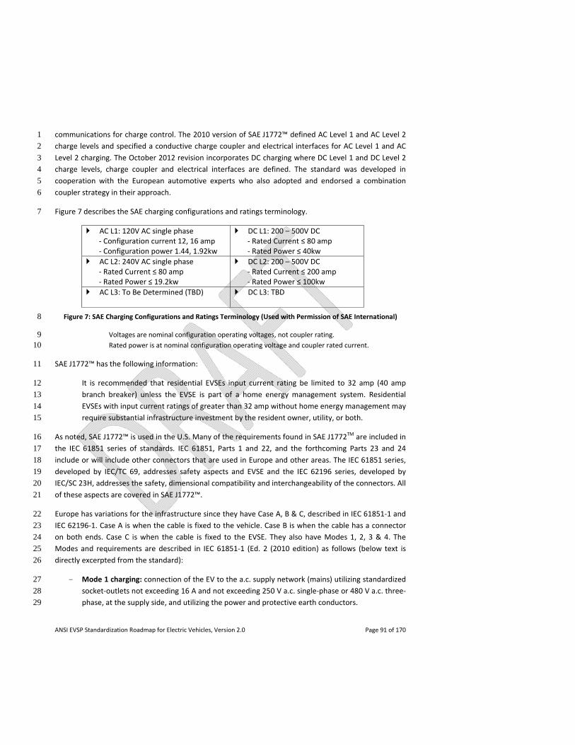
ANSI EVSP Standardization Roadmap for Electric Vehicles, Version 2.0 Page 91 of 170
communications for charge control. The 2010 version of SAE J1772™ defined AC Level 1 and AC Level 2 1
charge levels and specified a conductive charge coupler and electrical interfaces for AC Level 1 and AC 2
Level 2 charging. The October 2012 revision incorporates DC charging where DC Level 1 and DC Level 2 3
charge levels, charge coupler and electrical interfaces are defined. The standard was developed in 4
cooperation with the European automotive experts who also adopted and endorsed a combination 5
coupler strategy in their approach. 6
Figure 7 describes the SAE charging configurations and ratings terminology. 7
AC L1: 120V AC single phase ‐ Configuration current 12, 16 amp ‐ Configuration power 1.44, 1.92kw
DC L1: 200 – 500V DC ‐ Rated Current ≤ 80 amp ‐ Rated Power ≤ 40kw
AC L2: 240V AC single phase ‐ Rated Current ≤ 80 amp ‐ Rated Power ≤ 19.2kw
DC L2: 200 – 500V DC ‐ Rated Current ≤ 200 amp ‐ Rated Power ≤ 100kw
AC L3: To Be Determined (TBD)
DC L3: TBD
Figure 7: SAE Charging Configurations and Ratings Terminology (Used with Permission of SAE International) 8
Voltages are nominal configuration operating voltages, not coupler rating. 9 Rated power is at nominal configuration operating voltage and coupler rated current. 10
SAE J1772™ has the following information: 11
It is recommended that residential EVSEs input current rating be limited to 32 amp (40 amp 12
branch breaker) unless the EVSE is part of a home energy management system. Residential 13
EVSEs with input current ratings of greater than 32 amp without home energy management may 14
require substantial infrastructure investment by the resident owner, utility, or both. 15
As noted, SAE J1772™ is used in the U.S. Many of the requirements found in SAE J1772TM are included in 16
the IEC 61851 series of standards. IEC 61851, Parts 1 and 22, and the forthcoming Parts 23 and 24 17
include or will include other connectors that are used in Europe and other areas. The IEC 61851 series, 18
developed by IEC/TC 69, addresses safety aspects and EVSE and the IEC 62196 series, developed by 19
IEC/SC 23H, addresses the safety, dimensional compatibility and interchangeability of the connectors. All 20
of these aspects are covered in SAE J1772™. 21
Europe has variations for the infrastructure since they have Case A, B & C, described in IEC 61851‐1 and 22
IEC 62196‐1. Case A is when the cable is fixed to the vehicle. Case B is when the cable has a connector 23
on both ends. Case C is when the cable is fixed to the EVSE. They also have Modes 1, 2, 3 & 4. The 24
Modes and requirements are described in IEC 61851‐1 (Ed. 2 (2010 edition) as follows (below text is 25
directly excerpted from the standard): 26
- Mode 1 charging: connection of the EV to the a.c. supply network (mains) utilizing standardized 27
socket‐outlets not exceeding 16 A and not exceeding 250 V a.c. single‐phase or 480 V a.c. three‐28
phase, at the supply side, and utilizing the power and protective earth conductors. 29
ANSI EVSP Standardization Roadmap for Electric Vehicles, Version 2.0 Page 92 of 170
NOTE 2 In the following countries, mode 1 charging is prohibited by national codes: US. 1
2
NOTE 3 The use of an in‐cable RCD can be used to add supplementary protection for connection 3
to existing a.c. supply networks. 4
NOTE 4 Some countries may allow the use of an RCD of type AC for mode 1 vehicles connected 5
to existing domestic installations: JP, SE. 6
- Mode 2 charging: connection of the EV to the a.c. supply network (mains) not exceeding 32 A 7
and not exceeding 250 V a.c. single‐phase or 480 V a.c. three‐phase utilizing standardized single‐8
phase or three‐phase socket‐outlets, and utilizing the power and protective earth conductors 9
together with a control pilot function and system of personnel protection against electric shock 10
(RCD) between the EV and the plug or as a part of the in‐cable control box. The inline control 11
box shall be located within 0,3 m of the plug or the EVSE or in the plug. 12
NOTE 5 In the USA, a device which measures leakage current over a range of frequencies and 13
trips at predefined levels of leakage current, based upon the frequency is required. 14
NOTE 6 In the following countries, according to national codes, additional requirements are 15
necessary to allow cord and plug connection to a.c. supply networks greater than 20 A, 125 V 16
a.c.: US. 17
NOTE 7 For mode 2, portable RCD as defined in IEC 61540 and IEC 62335 is applicable. 18
NOTE 8 In Germany the inline control box (EVSE) shall be in the plug or located within 2,0 m of 19
the plug. 20
- Mode 3 charging: connection of the EV to the a.c. supply network (mains) utilizing dedicated 21
EVSE where the control pilot function extends to control equipment in the EVSE, permanently 22
connected to the a.c. supply network (mains). 23
- Mode 4 charging: connection of the EV to the a.c. supply network (mains) utilizing an offboard 24
charger where the control pilot function extends to equipment permanently connected to the 25
a.c. supply. 26
It is recognized that vehicle manufacturers may have to design vehicles with regional kits that will allow 27
the appropriate connector and voltage interface for the region of use. 28
Partial Gap: EVSE charging levels. At the time of release of version 1.0 of this roadmap, the levels for DC 29
charging within SAE J1772TM had yet to be finalized. 30
Recommendation: Complete work to establish DC charging levels within SAE J1772TM. Priority: Near‐31
term. Potential Developer: SAE. Grid Related: Yes. Status of Progress: Closed. Update: With the 32
publication of the new version of SAE J1772™, the gap identified in version 1.0 of this roadmap with 33
respect to DC charging levels in SAE J1772™ is now closed. 34
ANSI EVSP Standardization Roadmap for Electric Vehicles, Version 2.0 Page 93 of 170
EV Supply Equipment and Charging Systems 1
Off‐board charging stations and portable EV cord sets are covered by UL 2594, Standard for Electric 2
Vehicle Supply Equipment. Off‐board chargers are covered by UL 2202, the Standard for Electric Vehicle 3
(EV) Charging Equipment. 4
A North American harmonization effort has taken place based on UL 2594 involving CSA C22.2 No. 280 5
and similar requirements in Mexico to cover the safety requirements for off‐board charging stations and 6
portable EV cord sets, with respect to risk of fire, shock and injury to persons. As a result of this work, a 7
tri‐national standard was published in February 2013: NMX‐J‐677‐ANCE/CSA C22.2 NO. 280‐13/UL 2594, 8
Standard for Electric Vehicle Supply Equipment. This aligns with the timing of the revision cycle of the 9
2014 National Electrical Code® (NEC®). There are additional technical items that will be addressed in a 10
Phase 2 harmonization effort through CANENA (Council for Harmonization of Electrotechnical Standards 11
of the Nations of the Americas) upon the completion of this initial phase of harmonization. 12
UL 2594 references UL 2231 (Parts 1 and 2) as well as UL 2251, Standard for Plugs, Receptacles and 13
Couplers for Electric Vehicles whose requirements are also being harmonized with CSA and ANCE to 14
create North American standards. 15
In September 2012, the first two of these standards were published as North American standards. These 16
were based on UL 2231‐1 and 2231‐2 respectively. 17
- NMX‐J‐668/1‐ANCE / CSA C22.2 No. 281.1 / UL 2231‐1 Standard for Safety for Personnel 18
Protection Systems for Electric Vehicle (EV) Supply Circuits: General Requirements; 19
- NMX‐J‐668/2‐ANCE / CSA C22.2 No. 281.2 / UL 2231‐2 Standard for Safety for Personnel 20
Protection Systems for Electric Vehicle (EV) Supply Circuits: Particular Requirements for 21
Protective Devices for Use in Charging Systems. 22
These documents cover device and systems intended for use in accordance with the NEC® Article 625 to 23
reduce the risk of electric shock to the user from accessible parts, in grounded or isolated circuits for 24
charging electric vehicles. They are intended to be read together. 25
Partial Gap: Off‐board charging station and portable EV cord set safety within North America. At the 26
time of release of version 1.0 of this roadmap, the harmonization of equipment safety standards within 27
North America based on the UL 2594 standard was still underway. 28
Recommendation: Finish North American harmonization effort based on UL 2594 addressing off‐board 29
charging station and portable EV cord set safety Priority: Near‐term. Potential Developer: UL, CSA, 30
ANCE (Mexico), NEMA. Grid Related: Yes. Status of Progress: Closed. Update: With the publication of 31
the tri‐national North American standard based on UL 2594 in February 2013, the partial gap identified 32
in version 1.0 of this roadmap regarding off‐board charging station and portable EV cord set safety 33
within North America is closed. There will be a need to address NEC® 2014 technical issues in the new 34
ANSI EVSP Standardization Roadmap for Electric Vehicles, Version 2.0 Page 94 of 170
tri‐national standard. There are additional technical items that will be addressed in a Phase 2 1
harmonization effort through CANENA. 2
There is currently no harmonization effort in progress for UL 2202. However, the harmonization of the 3
safety requirements for off‐board chargers would be needed to address safety concerns in the same 4
manner as harmonization of UL 2594 as stated above. 5
Partial Gap: Off‐board charger safety within North America. Harmonization of equipment safety 6
standards within North America is needed. 7
Recommendation: There appears to be a need to harmonize the safety requirements for off‐board 8
chargers with the U.S., Canada, and Mexico. Priority: Mid‐term. Potential Developer: UL, CSA, ANCE 9
(Mexico), NEMA. Grid Related: Yes. Status of Progress: Not started. 10
The IEC 61851 series of standards also address the safety of off‐board chargers, off‐board charging 11
stations, and portable EV cord sets: 12
- IEC 61851‐1, Ed. 2.0, Electric Vehicle Conductive Charging Systems, Part 1: General 13
Requirements, (Ed. 3.0 currently under development with an anticipated publication date of 14
March 2014); and 15
- IEC 61851‐22, Ed. 2.0, Electric Vehicle Conductive Charging Systems, Part 22: AC Electric Vehicle 16
Charging Stations (will be withdrawn upon publication of IEC 61851‐1, Ed. 3.0). 17
The following standards are also under development in IEC/TC 69: 18
− IEC 61851‐21‐1, Ed. 1.0, Electric vehicle conductive charging system – EMC requirements for 19
electric vehicle for conductive connection to an a.c./d.c. supply (publication anticipated in 20
March 2014); 21
− IEC 61851‐21‐2, Ed. 1.0, Electric vehicle conductive charging system – EMC requirements for off 22
board electric vehicle charging systems (publication anticipated in March 2014); 23
These two new parts are intended to replace the existing IEC 61851‐21, Ed. 1.0 (2001) Electric vehicle 24
conductive charging system ‐ Part 21: Electric vehicle requirements for conductive connection to an 25
a.c./d.c. supply. This original Part 21 will be withdrawn, and replaced by the two subparts 1 and 2 noted 26
above. The electrical requirements are being split and included in IEC 61851‐1 and ISO 6469‐3 and ISO 27
17409. The work to develop a 2nd Edition of Part 21 has been stopped and will likely be canceled when 28
Parts 21‐1 and 21‐2 are published. 29
Also being developed are: 30
- IEC 61851‐23, Ed. 1.0, Electric vehicle conductive charging system – D.C. electric vehicle charging 31
station (publication anticipated in December 2013); and 32
ANSI EVSP Standardization Roadmap for Electric Vehicles, Version 2.0 Page 95 of 170
- IEC 61851‐24, Ed. 1.0, Electric vehicle conductive charging system – Digital communication 1
between a d.c. EV charging station and an electric vehicle for control of d.c. charging 2
(publication targeted for February 2014). 3
The IEC 61851‐1 and 61851‐22 standards have many requirements that are similar or identical to what is 4
featured in the North American standards, such as UL 2594 and UL 2202. However, an area of 5
discrepancy exists pertaining to the requirements for personnel protection systems. The IEC documents 6
require a form of protection system that is widely used in Europe but is not used in the U.S., while the 7
National Electrical Code® in the U.S. requires a different system of protection that is not used in Europe. 8
This difference in the standards affects the harmonization of these requirements. In addition, there are 9
differences in the standards used to cover components or subassemblies within the overall equipment, 10
and differences in the evaluation of required environmental ratings for outdoor equipment. From a 11
harmonization perspective, these differences are not as difficult to overcome as the previously 12
discussed personnel protection systems. 13
Harmonization between the North American safety standards and the IEC 61851 standards is being 14
driven through IEC work and U.S. participation in the appropriate IEC committees. However, no formal 15
program or specific project has been initiated to actually harmonize these standards. Up to this point, 16
the effort has been focused on introducing specific aspects into either the North American standards, or 17
the IEC standards, as opportunity allows. 18
Partial Gap: Off‐board charger, off‐board charging station and portable EV cord set safety globally. 19
There are some differences between the IEC 61851 series of standards and the North American 20
standards. While not a gap per se with respect to the U.S. market, the use of infrastructure equipment 21
and the means to mitigate risks would prove beneficial to manufacturers if harmonization was 22
completed. 23
Recommendation: Work to harmonize the IEC 61851 series standards and the North American 24
standards. Priority: Mid‐term. Potential Developer: UL, IEC. Grid Related: Yes. Status of Progress: Not 25
started. 26
Conformance Programs 27
Various conformance programs exist, with each third party testing organization having a program in 28
place. Article 625 of the National Electrical Code® requires off‐board chargers, off‐board charging 29
stations, and portable EV cord sets to be listed. So, conformance programs are essential to listing the 30
product. Although all conformance programs have their own specific parts, for off‐board charging 31
stations and portable EV cord sets, all North American conformance programs will be based on the 32
North American standards as shown above, and all will eventually be using the new harmonized tri‐33
national standard (based on UL 2594). 34
ANSI EVSP Standardization Roadmap for Electric Vehicles, Version 2.0 Page 96 of 170
EV Couplers: Safety and Harmonization Efforts 1
Today, UL 2251, Standard for Plugs, Receptacles and Couplers for Electric Vehicles, exists to cover for EV 2
couplers. A North American harmonization effort has taken place based on UL 2251 involving CSA C22.2 3
No. 282 and similar Mexican documents to cover the safety requirements for vehicle connectors and 4
vehicle inlets with respect to the risk of fire, shock, and injury to persons for both AC and DC rated EV 5
couplers. As a result of this work, a tri‐national standard was published in February 2013: NMX‐J‐678‐6
ANCE/CSA C22.2 No. 282‐13/UL 2251, Standard for Plugs, Receptacles and Couplers for Electric Vehicles. 7
Partial Gap: EV coupler safety within North America. At the time of publication of version 1.0 of this 8
roadmap, harmonization of EV coupler safety standards within North America based on the UL 2251 9
standard was still underway. 10
Recommendation: Finish efforts to harmonize standards addressing EV coupler safety within North 11
America. Priority: Near‐term. Potential Developer: UL, CSA, ANCE (Mexico), NEMA. Grid Related: Yes. 12
Status of Progress: Closed. Update: With the publication of the tri‐national standard based on UL 2251 13
in February 2013, there are no gaps in standardization for EV coupler safety in North America and the 14
partial gap identified in version 1.0 of this roadmap is closed. There are additional technical items that 15
will be addressed in a Phase 2 harmonization effort through CANENA. 16
The IEC 62196 series of standards also address safety of the EV coupler: 17
- IEC 62196‐1, Ed. 2.0, Plugs, Socket‐Outlets, Vehicle Connectors and Vehicle Inlets – Conductive 18
Charging of Electric Vehicles – Part 1: General Requirements; and 19
- IEC 62196‐2, Ed. 1.0, Plugs, Socket‐Outlets, Vehicle Connectors and Vehicle Inlets – Conductive 20
Charging of Electric Vehicles – Part 2: Dimensional Compatibility and Interchangeability 21
Requirements for AC Pin and Contact‐Tube Accessories. 22
Based upon the continuing development of EV couplers and EV charging stations, IEC 62196 parts 1 and 23
2 are in a revision phase started in 2012 and continuing through 2013, with publication of new editions 24
expected in the first half of 2014. 25
In addition to IEC 62196 parts 1 and 2, a new Part 3, Dimensional Compatibility and Interchangeability 26
Requirements for Dedicated DC and combined AC/DC Pin and Contact‐Tube Vehicle Couplers, is being 27
developed. It will be similar to Part 2 in that it will standardize and contain all of the details to build 28
either DC or AC/DC vehicle couplers. Publication is anticipated during the first half of 2014. 29
The IEC 62196 standards are similar in many respects to the North American standards. They go further 30
in that the Part 2 and the developing Part 3 include or will include the specific vehicle inlet and 31
connector interface (configuration) drawings, ratings information and other details to allow 32
interchangeable devices to be made by many manufacturers. They also insure that other types of 33
vehicle couplers used in other countries will not mismatch with the devices recommended by U.S. 34
manufacturers. 35
ANSI EVSP Standardization Roadmap for Electric Vehicles, Version 2.0 Page 97 of 170
There are some differences between IEC 62196 series standards and the existing North American 1
standards. These include some construction issues such as acceptance of components and the IEC 2
standards used to certify and test these components, the mandatory use of latching means, and the use 3
of IEC ingress protection (IP) ratings. They also include testing differences such as additional test 4
methods for enclosure strength testing, environmental testing on enclosures (IP ratings), and impact 5
testing on inlets. 6
Harmonization between the North American coupler safety standards and the IEC 62196 standards is 7
being driven through IEC work and U.S. participation in the appropriate IEC committees. However, no 8
formal program or specific project has been initiated to actually harmonize these standards. Up to this 9
point, the effort has been focused on introducing specific aspects into either the North American 10
standards, or the IEC standards, as opportunity allows. The fact that harmonized standards do not exist 11
globally creates the situation where different connectors are being used in different geographic areas. In 12
some cases, these differences cannot be eliminated because of differences in the infrastructure. In other 13
cases, harmonization would be a good thing, but at the moment it would appear to be more of a mid‐14
term goal. 15
Partial Gap: EV coupler safety globally. There are some differences between the IEC 62196 series 16
standards and the North American EV coupler safety standards. While not a gap per se with respect to 17
the U.S. market, global harmonization would help to reduce costs for vehicle manufacturers. 18
Recommendation: Work to harmonize the IEC 62196 series standards and the North American EV 19
coupler safety standards. Priority: Mid‐term. Potential Developer: UL, IEC. Grid Related: Yes. Status of 20
Progress: Not started. 21
Conformance Programs 22
Section 1962.2, Title 13, of the California Code of Regulations, requires 2006 and later model year 23
vehicles to be equipped with a conductive charger inlet port which meets all the specifications 24
contained in SAE J1772™. This is also a requirement in states that have adopted the California Air 25
Resources Board (CARB) zero emission vehicle (ZEV) requirements pursuant to section 177 of the federal 26
Clean Air Act (42. U.S.C. Sec. 7507) (“S.177 states”). In March 2012, section 1962.2, Title 13, was 27
amended so as to permit a manufacturer to apply for approval to use an alternative to the AC inlet 28
specified in SAE J1772™ provided that the following conditions are met: (a) each vehicle is supplied with 29
a rigid adaptor that would enable the vehicle to meet all of the remaining system and on‐board charger 30
requirements described in J1772™, and (b) the rigid adaptor and alternative inlet must be tested and 31
approved by a Nationally Recognized Testing Laboratory. 32
Various other conformance programs exist, with each third party testing organization having a program 33
in place. Article 625 of the National Electrical Code® requires EV couplers, EVSE and EV charging systems 34
to be listed. So, conformance programs are essential to listing the product. Although all conformance 35
programs have their own specific parts, all North American conformance programs will be based on the 36
North American standards as shown above, and all will eventually be using the new harmonized tri‐37
national standard (based on UL 2251). 38
ANSI EVSP Standardization Roadmap for Electric Vehicles, Version 2.0 Page 98 of 170
EV Couplers: Interoperability with EVSE and Harmonization Efforts 1
SAE J1772™ covers the interface, design, geometry, communication protocol, and pilot controls for 2
electric vehicle infrastructure as it is communicated through the EV connector. Conforming to this SAE 3
document means that any vehicle supplied with an SAE J1772™ inlet on the vehicle can pull up to any 4
SAE J1772™ infrastructure type device (which would be provided with an SAE J1772™ style connector) 5
and be able to charge the vehicle. Such charging interoperability is key to the mass deployment of PEVs. 6
As noted above, compliance requirements with respect to SAE J1772TM and the charger inlet port are 7
specified in California’s ZEV requirements which also apply to S.177 states. As such, it is currently the de 8
facto EV charge coupler standard in the U.S. 9
Outside of the U.S. market, EV couplers are diverse: 10
- For AC charging, different connectors exist in Europe and China, while Japan uses the SAE 11
J1772™ EV coupler and Korea has adapted SAE J1772™ to allow for a detachable charge cable; 12
and 13
- For DC charging, Europe and China are developing their own EV coupler, while Japan is using the 14
CHAdeMO configuration, and Korea has looked at both CHAdeMO, a modification of it, and SAE 15
J1772™. 16
This diversity in the EV coupler has caused the need for different products to be manufactured for 17
different countries as well as modifications to vehicles that will be shipped around the world. 18
As explained earlier, SAE International has revised the SAE J1772™ standard to include both AC and DC 19
fast charging capabilities via the AC/DC combination coupler. The forthcoming IEC 62196‐3 will describe 20
the new SAE J1772™ combination coupler as well several other different DC coupler configurations 21
(Japan, China, and Europe). 22
To date, the CHAdeMO configuration has been widely deployed for DC charging in North America. It is 23
anticipated that vehicles and infrastructure outfitted to accommodate the new SAE J1772™ combination 24
coupler will come to market in 2013. 25
Harmonization of EV couplers on a global scale would help to reduce costs for manufacturers of PEVs 26
and charging infrastructure. However, due to differences in electrical systems, each country’s own 27
national rules and regulations, EV coupler configurations already having been well established in some 28
locations, global harmonization is not likely to occur. Also, with the advent of DC quick charging, the 29
need to harmonize AC connectors has become less of an issue. Once sufficient infrastructure is in place, 30
it may prove difficult to switch connector types, so the harmonization effort for DC connectors would be 31
considered a near‐term goal if it is going to happen. 32
Partial Gap: EV coupler interoperability with EVSE globally. Different coupler configurations are used in 33
different parts of the world. Global harmonization would help to reduce costs for manufacturers. At the 34
ANSI EVSP Standardization Roadmap for Electric Vehicles, Version 2.0 Page 99 of 170
time of release of version 1.0 of this roadmap, the revision of SAE J1772TM was still in progress; it has 1
now been published. 2
Recommendation: Incorporate the new SAE J1772™ combination coupler into IEC 62196‐3. Build out the 3
charging infrastructure to accommodate variations in EV coupler configurations for particular markets as 4
necessary, in particular with respect to DC charging. Priority: Near‐term. Potential Developer: SAE, IEC, 5
CHAdeMO, vehicle and charging station manufacturers. Grid Related: Yes. Status of Progress: Green. 6
Update: The roadmap version 1.0 text has been updated to note the publication of the SAE J1772TM 7
AC/DC combination coupler and that the forthcoming IEC 62196‐3 will describe the SAE J1772™ coupler 8
and several other different DC coupler configurations used elsewhere. The gap statement notes the 9
publication of SAE J1772TM. The recommendation notes the need to incorporate SAE J1772TM into IEC 10
62196‐3 and the need to build out the charging infrastructure to accommodate variations in coupler 11
configurations for particular markets as necessary, in particular with respect to DC charging. CHAdeMO, 12
and “vehicle and charging station manufacturers,” have been added alongside SAE and IEC as “potential 13
developers.” 14
Conformance Programs 15
SAE is developing J2953, Plug‐In Electric Vehicle (PEV) Interoperability with Electric Vehicle Supply 16
Equipment (EVSE), which will address interoperability in terms of both hardware requirements and 17
communication protocols between PEVs and EVSE for multiple suppliers. A draft of the first part is 18
expected to be published in the Spring of 2013. 19
There is also a verification program currently being developed by Underwriters Laboratories, Inc. that 20
may be used to prove that infrastructure equipment, which includes the vehicle connector, will be 21
compatible with all vehicles that meet the SAE J1772™ protocol for AC charging. A similar program is 22
under development in Japan for the CHAdeMO EV coupler. 23
Gap: Conformance programs for EV coupler interoperability within the U.S. market. A program(s) is 24
needed for the U.S. market to verify compatibility between the EV coupler, the infrastructure and the 25
vehicle. 26
Recommendation: Complete work on SAE J2953. Establish a program(s) to verify interoperability 27
between infrastructure equipment, including the vehicle connector, and all vehicles that follow the SAE 28
J1772™ protocol. Priority: Near‐term. Potential Developer: SAE, UL. Grid Related: Yes. Status of 29
Progress: Green. 30
Light Electric Vehicles (LEV) 31
IEC/TC 69 has approved a new work proposal for a new 61851 Part 3, with subparts, to include 32
requirements for power supply systems for Light Electric Vehicles (LEV), including electric motorcycles, 33
bicycles and scooters. 34
The proposed standards will include: 35
ANSI EVSP Standardization Roadmap for Electric Vehicles, Version 2.0 Page 100 of 170
- IEC 61851‐3‐1, Electric Vehicles conductive power supply system ‐ Part 3‐1: General 1
Requirements for Light Electric Vehicles (LEV) AC and DC conductive power supply systems; 2
- IEC 61851‐3‐2, Electric Vehicles conductive power supply system ‐ Part 3‐2: Requirements for 3
Light Electric Vehicles (LEV) DC off‐board conductive power supply systems; 4
- IEC 61851‐3‐3, Electric Vehicles conductive power supply system ‐ Part 3‐3: Requirements for 5
Light Electric Vehicles (LEV) battery swap systems; and 6
- IEC 61851‐3‐4, Electric Vehicles conductive power supply system ‐ Part 3‐4: Requirements for 7
Light Electric Vehicles (LEV) communication. 8
This work will be done jointly with ISO TC 22/SC 22 & SC 23, with IEC/TC 69 having the lead. A first 9
meeting is planned for May 2013, with a target for publication of July 2015. 10
The National Electrical Code® includes neighborhood electric vehicles and electric motorcycles in the 11
definition of EV because these are on‐road vehicles that are expected to use the same or similar 12
charging infrastructure as a car. However, there is not yet any standards activity in the U.S. specific for 13
LEVs except for UL 2271, Batteries for use in Light Electric Vehicles (LEV), which covers both on‐road and 14
off‐road vehicles including electric bicycles, electric scooters and electric wheel chairs. These types of 15
vehicles are not expected to use the same charging infrastructure as an EV. In addition, off‐road vehicles 16
are excluded in the NEC® definition of EV. 17
4.2.1.4 Electromagnetic Compatibility (EMC) 18
SAE J551‐1, Performance Levels and Methods of Measurement of Electromagnetic Compatibility of 19
Vehicles, Boats (up to 15 m), and Machines (16.6 Hz to 18 GHz), covers the measurement of radio 20
frequency (rf) radiated emissions and immunity. Each part details the requirements for a specific type of 21
electromagnetic compatibility (EMC) test and the applicable frequency range of the test method. The 22
methods are applicable to a vehicle . . . powered by an internal combustion engine or battery powered 23
electric motor. As all of the vehicle tests are evaluating the complete vehicle, the source of power is 24
immaterial. SAE J551‐1 adopts by reference IEC CISPR 12 and CISPR 25 which apply to all vehicles and 25
other equipment. CISPR 25 is in the process of being updated to adapt the test methods to safely test 26
high voltage components in the vehicle. The SAE J1113 series covers EMC testing of vehicle components. 27
Presently, the only EV‐specific standard for EMC is SAE J551‐5‐2012, Performance Levels and Methods of 28
Measurement of Magnetic and Electric Field Strength from Electric Vehicles, 9 kHz to 30 MHz, which 29
covers conducted emission measurements that are applicable only to battery‐charging systems which 30
utilize a switching frequency above 9 KHz, are mounted on the vehicle, and whose power is transferred 31
by metallic conductors. Conducted emission requirements apply only during charging of the batteries 32
from AC power lines. Conducted and radiated emissions measurements of battery‐charging systems that 33
use an induction power coupling device are not covered; radiated emissions for an electric vehicle in 34
operation at a constant speed are covered. 35
ANSI EVSP Standardization Roadmap for Electric Vehicles, Version 2.0 Page 101 of 170
As noted earlier, the following standards are under development in IEC/TC 69, both with an anticipated 1
publication date of March 2014: 2
− IEC 61851‐21‐1, Ed. 1.0, Electric vehicle conductive charging system – EMC requirements for 3
electric vehicle for conductive connection to an a.c./d.c. supply; and 4
− IEC 61851‐21‐2, Ed. 1.0, Electric vehicle conductive charging system – EMC requirements for off 5
board electric vehicle charging systems. 6
Apparently, concerns are being raised on the limits contained in the committee draft for vote (CDV) for 7
IEC 61851‐21‐2 that are being worked with IEC CISPR/B and the IEC Advisory Committee on 8
Electromagnetic Compatibility (ACEC). There is a current international agreement between IEC and 9
ISO regarding EMC as follows: EMC immunity issues relating to vehicles (internal combustion, battery, 10
fuel cell or hybrid powered) while not connected to the power grid are the responsibility of ISO/TC 22 11
and rf emissions are the responsibility of IEC CISPR/D. EMC issues relating to vehicles while connected to 12
the power grid for charging are the responsibility of IEC/TC 69 with IEC CISPR/B having responsibility for 13
emissions during charging. All of the activities are to take into account the basic IEC/TC 77 EMC 14
standards (the IEC 61000 series) where appropriate. 15
In terms of EMC standards for the electric grid, the main source is the IEC 61000 series. The 61000 series 16
has several parts that cover everything from the general application of the standard (part 1), through 17
discussions of environment, limits, testing and measurement, installation and mitigation, and finally a 18
generic catchall volume (parts 2 through 6 respectively). Propagated by various subcommittees of 19
IEC/TC 77, Electromagnetic compatibility, between electrical equipment including networks, the 61000 20
series has broad applicability in the infrastructure segment of the EV space. 21
IEC CISPR/D and ISO/TC 22/SC 3/WG 3 have been meeting back‐to‐back on a regular basis to address the 22
vehicle EMC issue while not connected to the power grid. CISPR has a liaison relationship with IEC/TC 69. 23
In addition, CISPR/B has been interacting with IEC/TC 69 in regard to emissions and the applicability of 24
CISPR 11 during charging. 25
The SAE Surface Vehicle EMC (SV) Standards Committee is also addressing EMC issues. Subsets of this 26
committee form the U.S. TAGS for CISPR/D and ISO/TC 22/SC 3/WG 3, respectively. There are SAE 27
product committees that are addressing the charging of electric vehicles. SAE J1772TM includes EMC 28
requirements for the conductive charging interface unit, referring to UL 2231‐2 and FCC part 15. SAE 29
J2954 is under development and will address inductive charging of electric vehicles. The SV EMC 30
Standards Committee is supporting the J2954 document development in regard to rf issues. 31
Gap: Electromagnetic Compatibility (EMC). Standards to address EMC issues related to electric vehicle 32
charging are still in development. 33
Recommendation: Complete work on IEC 61851‐21, Parts 1 and 2, and SAE J2954 to address EMC issues 34
related to electric vehicle charging. Priority: Near‐term. Potential Developer: IEC/TC 69, SAE. Grid 35
Related: Yes. Status of Progress: New gap / Green. 36
ANSI EVSP Standardization Roadmap for Electric Vehicles, Version 2.0 Page 102 of 170
4.2.1.5 Vehicle as Supply 1
Activities related to the EV as a distributed energy resource (DER) are being pursued by SAE and by the 2
International Electrotechnical Commission (IEC). In many areas, these activities are being coordinated, 3
such as the use cases, the DER functions for EVs, and the abstract object modeling. However, in a few 4
areas distinctly different approaches are being taken, primarily with respect to the expected 5
communications architectures and the protocols between the EV and external systems. 6
This coordination has been strong for use cases and the DER functions. SAE J2836/3TM, published in 7
January 2013, provides use cases for EV communication as a DER to allow an EV to support V2G 8
applications serving the bulk grid, the distribution system, and behind the meter in a facility. The 9
information exchange with the EV for these use cases was derived from the IEC/TR 61850‐90‐7 (TR 10
signifies technical report, expected to be published in the first quarter of 2013) which, in part, defines 11
object models for inverter‐based storage devices. The IEC plans to incorporate the changes defined by 12
this technical report in the next planned update of the IEC 61850‐7‐420 standard. SAE J2836/3TM 13
includes some additional information for using an EV as a DER, versus a stationary storage device, which 14
should also be included in the planned revision of IEC 61850‐7‐420. 15
However, divergence is occurring when these DER functions are mapped to protocols. SAE is planning to 16
use the Smart Energy Profile 2.0 (SEP 2.0), while it is unlikely that the IEC will accept SEP 2.0 as the 17
preferred protocol, partly due to its use of the RESTful web services approach. 18
The DER function in SEP 2.0 is based on IEC/TR 61850‐90‐7 but also includes the additional information 19
required by SAE J2836/3TM. SAE J2847/3, currently in development, shows how the Flow Reservation 20
and DER functions of SEP 2.0 can be used to implement the use cases and V2G applications defined in 21
J2836/3TM. These additional information items are being provided back to the IEC for possible update of 22
the object models in appropriate IEC documents (such as IEC/TR 61850‐90‐8 that is still in development 23
and eventually IEC 61850‐7‐420). 24
While the primary purpose of SAE J2836/3TM is to present use cases for communication with a PEV as a 25
DER, this document also provides a broader view of the issues associated with reverse power flow. It 26
defines some “requirements” for reverse power flow (RPF), but because the document is only a 27
technical information report, any actual requirements will need to be incorporated in future revisions of 28
actual recommended practices and standards. SAE J2847/3 will achieve this for DER communications. 29
Architecture and safety aspects associated with reverse flow would need to be incorporated in SAE 30
1772TM and other standards. 31
The customer interfaces and selection for these features will be included in SAE J2836/5™ and J2847/5. 32
The /5 documents include the two networks that are: (1) the Customer Network for Customer to EV and 33
Home Area Network (HAN)/Neighborhood Area Network (NAN) interface and (2) the Utility Network for 34
Energy Services Interface (ESI) to EVSE/EV communication. As with the /3 documents, SAE J2836/5™ 35
identifies the use case and general information that corresponds to SAE J2847/5 for messages details. 36
This is a coordinated effort of the EV, EVSE and ESI for the various combinations of RPF. 37
ANSI EVSP Standardization Roadmap for Electric Vehicles, Version 2.0 Page 103 of 170
Section 625.26, Interactive Systems, of the NEC® provides that EVSE and other parts of a system, either 1
on‐board or off‐board the vehicle, that are identified for and intended to be interconnected to a vehicle, 2
and also serve as an optional standby system or an electric power production source, or provide for bi‐3
directional power feed, shall be listed as suitable for that purpose. When used as an “Optional Standby 4
System” (i.e., V2H), the requirements of Article 702 shall apply, and when used as an “Electric Power 5
Production Source” (i.e., V2G), the requirements of Article 705 shall apply. The on‐board or external 6
inverter is considered to be a “Utility‐Interactive Inverter” for which there are special requirements in 7
the NEC®. The NEC® adequately provides for an EV serving as either a standby system or a grid 8
interactive system and changes to the NEC® specifically to accommodate EV applications are not 9
anticipated. 10
The safety standard UL 1741, Inverters, Converters, Controllers and Interconnection System Equipment 11
for Use with Distributed Energy Resources, applies to an EV engaged in V2G. For utility‐interactive 12
equipment, UL 1741 is intended to supplement and be used in conjunction with IEEE 1547TM, Standard 13
for Interconnecting Distributed Resources with Electric Power Systems, and IEEE 1547.1TM, Standard for 14
Conformance Test Procedures for Equipment Interconnecting Distributed Resources with Electric Power 15
Systems. 16
IEEE 1547.4TM, Guide for Design, Operation, and Integration of Distributed Resource Island Systems with 17
Electric Power Systems, was released in July 2011 and may apply to certain V2G applications. IEEE 18
1547.8TM, Recommended Practice for Establishing Methods and Procedures that Provide Supplemental 19
Support for Implementation Strategies for Expanded Use of IEEE Standard 1547TM, is currently being 20
developed and will introduce new advanced capabilities for utility‐interactive inverters that could also 21
impact V2G operations. Updates to Article 705 of the NEC® and UL 1741 may be required to 22
accommodate new DER capabilities. 23
Gap: Vehicle as supply / reverse power flow. Differences exist between the DER model defined by SAE 24
J2836/3TM, IEC/TR 61850‐90‐7, IEC/TR 61850‐90‐8, and SEP 2.0. 25
Recommendation: Harmonize the information model for an EV as a DER between SAE J2836/3TM, IEC/TR 26
61850‐90‐8, and SEP 2.0. Priority: Near‐term. Potential Developer: SAE, IEC/TC 57, ZigBee Alliance and 27
the HomePlug Powerline Alliance. Grid Related: Yes. Status of Progress: Green. Update: The roadmap 28
version 1.0 text, gap statement, recommendation and list of potential developers have been 29
substantially reworked to focus specifically on the need for harmonization of the DER communications 30
model between SAE J2836/3TM, IEC/TR 61850‐90‐8, and SEP 2.0. Potential changes to other standards to 31
address integration of inverter‐based DER devices with the grid, or architecture and safety aspects of 32
reverse power flow, are contemplated in the text but not included as a gap. 33
4.2.1.6 Use of Alternative Power Sources 34
Much of the focus has been about electric vehicle charging using the bulk electric power system. But 35
there may be cases where alternative power sources could be used to provide power for charging an EV. 36
A solar PV array, small wind turbine, facility battery bank, or even another EV with reverse power flow 37
ANSI EVSP Standardization Roadmap for Electric Vehicles, Version 2.0 Page 104 of 170
capability could be used to provide power for charging an EV in a facility. These alternate sources could 1
operate as optional standby systems under Article 702 of the NEC® or as an electric power production 2
sources under Article 705 of the NEC® and provide AC power to the facility. The AC power could be used 3
for charging EVs and for other loads within the facility. However, it may be more efficient to use DC 4
power distribution rather than AC power distribution for this purpose. All of the facility power sources 5
as well as certain DC loads could connect to a DC power distribution system which would connect to the 6
electric power system using a single converter. 7
The EMerge Alliance is developing standards for a 380 VDC power distribution system. 600 VDC systems 8
have also been considered for use with PV arrays. It is not possible to directly connect an EV to a facility 9
DC power bus because of differences between the EV battery voltage and the facility bus voltage and 10
the need to precisely control the charging current into the EV battery. However this is easily done using 11
a DC to DC converter, such as a buck‐boost converter. The EVSE for DC charging is generally thought of 12
as an AC‐DC converter, or bi‐directional converter for reverse power flow, but a DC‐DC EVSE could easily 13
be used if the facility used a DC power distribution system. 14
Solar: ANSI/UL 1703, the standard for safety of photovoltaic (PV) equipment, and other UL standards, 15
address safety of PV modules. The National Electrical Code® contains requirements for PV systems in 16
Article 690. Car “sheds” with PV panel roofs and directly coupled EVSE beneath are being constructed 17
but are not specifically covered by standards at this time. 18
Wind: Small wind systems are addressed in NEC® Article 694. Consensus product standards are under 19
development for wind systems and should be published shortly. Wind power as a supply source is also 20
the subject of a proposed revision to the NEC® to include DC voltages up to 600 volts. 21
Battery banks: Battery banks are another alternative source of DC power. They can be charged off‐peak 22
and used to charge vehicles directly. Battery banks are being addressed by a code proposal on NEC® 23
Section 625.4 to include power sources up to 600 volts DC. 24
V2G and V2H: As discussed in the prior section, Vehicle to Grid (V2G) and Vehicle to Home (V2H) power 25
schemes have been discussed and anticipated. The reserved energy in an EV battery may be used for 26
power quality, power efficiency, or emergency source measures. Articles 702 and 705 of the NEC® 27
would apply to how the entire DC system connects through the utility‐interactive inverter to the electric 28
power system, but there is a gap for requirements between the EV and EVSE and the DC power 29
distribution system. 30
Gap: Use of alternative power sources. The National Electrical Code® does not specifically address the 31
integration of the EV and EVSE with a facility high voltage DC power distribution system for either 32
charging or reverse power flow. 33
Recommendation: Develop NEC® requirements for high voltage DC power distribution systems and the 34
integration of distributed energy resources and DC loads with the system. Priority: Near‐term. Potential 35
Developer: NFPA. Grid Related: Yes. Status of Progress: Green 36
ANSI EVSP Standardization Roadmap for Electric Vehicles, Version 2.0 Page 105 of 170
4.2.2 Infrastructure Communications 1
4.2.2.1 Communications Architecture for EV Charging 2
Most of the completed and ongoing standardization related to communications for EV charging 3
infrastructure has taken place within SAE International and the ISO/TC 22/SC 3 – IEC/TC 69 Joint 4
Working Group (JWG) developing the ISO/IEC 15118 standards. Other standards such as Smart Energy 5
Profile 2.0 (SEP 2.0), in development by the ZigBee Alliance and the HomePlug Powerline Alliance, and 6
Open Automated Demand Response (OpenADR), in development by the Open Smart Grid User’s Group 7
(OpenSG), are also incorporating EV charging‐related communications. 8
Currently, charging‐related communication between the EV and EVSE for conductive charging has been 9
standardized in SAE J1772TM (and in IEC 61851‐1). This communication is used to signal the readiness of 10
the EV to accept energy and of the EVSE to supply energy. It also allows the EVSE to determine if the EV 11
requires indoor ventilation and to signal the ampacity (maximum allowable current) that the EV should 12
consume. Verification of the connection, equipment grounding continuity, and proximity detection are 13
also provided. 14
SAE is currently developing standards for EV communication that go beyond SAE J1772TM and define 15
communications functions for utility communications, DC charging, reverse power flow, diagnostics, 16
Customer‐to‐EV/HAN/NAN, and wireless charging. Figure 8 shows the interaction between the SAE EV 17
communications standards documents. These can be stand‐alone (e.g., DC charging) or combined 18
(reverse power flow with off‐board conversion includes both SAE J2847/2 plus /3 messages). The figure 19
uses a Venn diagram approach to show the fundamental documents (SAE J2836™, J2847 & J2931) 20
“wrapped” by the interoperability document(s) J2953 and finally the security document J2931/7. 21
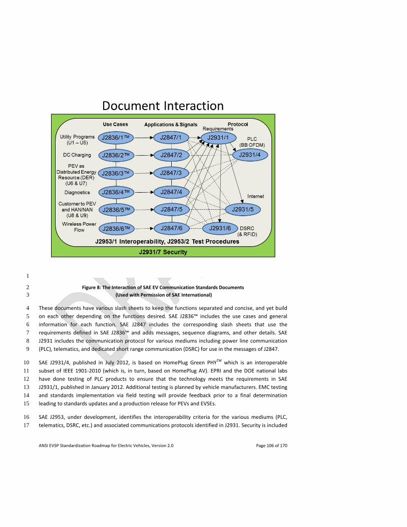
ANSI EVSP Standardization Roadmap for Electric Vehicles, Version 2.0 Page 106 of 170
1
Figure 8: The Interaction of SAE EV Communication Standards Documents 2 (Used with Permission of SAE International) 3
These documents have various slash sheets to keep the functions separated and concise, and yet build 4
on each other depending on the functions desired. SAE J2836™ includes the use cases and general 5
information for each function. SAE J2847 includes the corresponding slash sheets that use the 6
requirements defined in SAE J2836™ and adds messages, sequence diagrams, and other details. SAE 7
J2931 includes the communication protocol for various mediums including power line communication 8
(PLC), telematics, and dedicated short range communication (DSRC) for use in the messages of J2847. 9
SAE J2931/4, published in July 2012, is based on HomePlug Green PHYTM which is an interoperable 10
subset of IEEE 1901‐2010 (which is, in turn, based on HomePlug AV). EPRI and the DOE national labs 11
have done testing of PLC products to ensure that the technology meets the requirements in SAE 12
J2931/1, published in January 2012. Additional testing is planned by vehicle manufacturers. EMC testing 13
and standards implementation via field testing will provide feedback prior to a final determination 14
leading to standards updates and a production release for PEVs and EVSEs. 15
SAE J2953, under development, identifies the interoperability criteria for the various mediums (PLC, 16
telematics, DSRC, etc.) and associated communications protocols identified in J2931. Security is included 17
ANSI EVSP Standardization Roadmap for Electric Vehicles, Version 2.0 Page 107 of 170
specifically in J2931/7, under development, and may have slight variations dependent on Smart Energy 1
Profile (SEP) 2.0 utility requirements, DC charging/discharging, and where the PEV is controlling the off‐2
board unit for wireless charging communication. 3
Harmonization Efforts 4
The ISO/IEC Joint Working Group (JWG) is working on EV communication standards concurrently with 5
SAE. The ISO/IEC 15118 EV communications standards are related to the SAE documents as follows: 6
ISO/IEC 15118 part 1 identifies use cases, part 2 message details and communication protocol, and part 7
3 physical and data link communications layers. ISO/IEC 15118‐1 corresponds to SAE J2836™, while 8
15118‐2 and 15118‐3 correspond to various documents under the SAE J2847 and SAE J2931 series. The 9
ISO/IEC 15118 series also includes DC charging use cases and messages that correspond to dash 2 of SAE 10
J2836™ and J2847 (the same as in IEC 61851‐24, Annex C). 11
Also to be developed are: ISO/IEC 15118‐4, which defines the vehicle to grid communication network 12
and application protocol conformance test cases to be applied to EVs and EVSEs implementing ISO/IEC 13
15118‐2; and ISO/IEC 15118‐5, which defines the vehicle to grid communication physical layer and data 14
link layer conformance test to test the implementation of ISO/IEC 15118‐3. Both of these documents will 15
provide test cases representing the use cases in ISO/IEC 15118‐1, and include standard test case 16
attributes such as pre‐conditions, test steps, expected results to evaluate a pass or fail, and post‐17
conditions. SAE has a parallel standard J2953 focused on interoperability testing that will include test 18
cases harmonized with ISO/IEC 15118‐4 and 5. 19
In addition to the SAE and ISO/IEC standards, the Smart Energy Profile (SEP) 2.0 specification, based on 20
the OpenHAN requirements, is expected to provide much of the EV‐related services identified by 21
regulators, policy makers, ESPs/utilities, EVSPs and vendors. Though not EV specific, this standard‐in‐22
progress pertains to the energy‐related infrastructure (e.g., thermostats, plugs, meters, displays, EVSE, 23
EV, etc.). It specifies communications to be used for pricing, demand response load control (DRLC), 24
distributed energy resources (DER) control, metering, billing, and other functions. SEP 2.0 is harmonized 25
with J2836/1™ and is being used as the basis of a revision to J2847/1. 26
In addition to the coverage of DRLC in the SEP 2.0 specification, Open Automated Demand Response 27
(OpenADR) 2.0 contains EV‐specific communication and is expected to be harmonized with SEP 2.0 for 28
building infrastructure communication and aggregator functionality. It is anticipated that ESPs, and 29
possibly EVSPs, will use OpenADR for their automated demand response requirements. 30
For open and interoperable machine‐to‐machine (M2M) communication between entities such as ESPs 31
and EVSPs related to EV customer information (e.g., for pricing, metering, billing, and usage 32
information), the North American Energy Standards Board (NAESB) has completed work on the Energy 33
Services Provider Interface (ESPI) standard. A sub‐metering profile of Green Button Connect my Data 34
(using the ESPI format) is nearing completion. 35
The ISO/IEC JWG and Zigbee Alliance / HomePlug Powerline Alliance are working with SAE to harmonize 36
common standards related to utility and DC messaging. 37
ANSI EVSP Standardization Roadmap for Electric Vehicles, Version 2.0 Page 108 of 170
SAE utility messages (SAE J2847/1) correspond with the SEP 2.0 criteria per the Smart Energy 2.0 1
Technical Requirements Document (TRD) and the Application Specification that has now passed public 2
comment approval. SAE’s J2836/1™ use cases were included in the ZigBee + HomePlug Smart Energy 3
Marketing Requirements Document (MRD) that led to the TRD. 4
SAE is also working on the DC message format with the objective of harmonizing with ISO/IEC. DC 5
charging information in SAE J2847/2 is being included in Annex C of IEC 61851‐24, and ISO/IEC 15118‐2 6
is being included in Annex D. In the future, these annexes may be replaced by a harmonized solution in 7
the body of the IEC 61851‐24 document. As PLC testing continues, it is expected that goals can be met 8
and both utility and DC charging messages can be harmonized. 9
4.2.2.2 Communications Requirements for Various EV Charging Scenarios 10
Locating and Using Public Charging Stations (EVSE) 11
Public charging stations are already available and in use; however, there is no standardized method to 12
identify the location and capabilities of a charging station. Presently, such a capability is available for 13
only a subset of stations via Google Maps, websites of EVSPs, smartphone applications, or navigation 14
applications/devices. Notably, DOE provides an Alternative Fuel Station Locator database which includes 15
EV charging station information at: http://www.afdc.energy.gov/afdc/locator/stations/. 16
A well‐known registry of public charging stations combined with a standardized querying method would 17
enable the broadest public awareness and utilization. It is likely some information about a charging 18
station will be static (e.g., location, type) and can be queried from a global registry, but other 19
information (availability, pricing) will be dynamic and must be queried from the station or the managing 20
entity. 21
Reserving Charging Stations (EVSE): Due to the relatively long duration of EV charging, the ability to 22
reserve a charging station in advance will be useful to EV drivers. Standardization of the messaging 23
required to reserve a charging station would allow a driver to use a variety of methods (smartphone 24
application, website, etc.) to reserve a station. 25
Gap: Locating and reserving a public charging station. There is a need for a messaging standard to 26
permit EV drivers to locate a public charging spot and reserve its use in advance. 27
Recommendation: Develop a messaging standard to permit EV drivers to universally locate and reserve 28
a public charging spot. Priority: Mid‐term. Potential Developer: SAE, ISO/IEC JWG, NEMA. Grid Related: 29
Yes. Status of Progress: Green. Update: To address this roadmap version 1.0 gap, NEMA’s EVSE section 30
organized a working group (NEMA 5EVSE Network Roaming WG) to develop a standard that permits EV 31
drivers to universally locate a public charging spot. It decided that reserving a public charging spot was a 32
low priority and deferred action on reservations to a later phase of work. 33
Roaming: Public charging stations may be owned by hosts and managed by EVSPs. EV drivers may 34
subscribe to a charging plan offered by an EVSP (the Home EVSP). Roaming, in the context of EV 35
ANSI EVSP Standardization Roadmap for Electric Vehicles, Version 2.0 Page 109 of 170
charging, is the ability to charge at a charging station managed by a different EVSP (Visited EVSP), using 1
the subscription to the Home EVSP. 2
Communication related to roaming scenarios may take place directly between two EVSPs. Alternatively, 3
a third party financial clearinghouse may be required to act as an intermediary between the Home EVSP 4
and Visited EVSP(s). In order to support roaming scenarios, standardization is required for 5
authentication of the EV/driver, authorization of the EV/driver for a certain quality of service, relaying of 6
accounting records related to the charging session, and settlement of billing. 7
Gap: Charging of roaming EVs between EVSPs. There is a need to permit roaming EVs to charge at spots 8
affiliated with a different EVSP. 9
Recommendation: Develop back end requirements as well as an interface standard that supports 10
charging of roaming EVs between EVSPs. Priority: Near‐term. Potential Developer: NEMA, IEC. Grid 11
Related: Yes. Status of Progress: Green. Update: To address this roadmap version 1.0 gap, NEMA’s EVSE 12
section organized a working group (NEMA 5EVSE Network Roaming WG) to develop a standard that 13
supports roaming that allows charging services from a provider other than the Home EVSP. The standard 14
will include inter‐operator interfaces to address the various stages of a charging session (e.g., 15
authentication/authorization, charging data records, billing record exchange.) The NEMA working group 16
also is looking to develop a radio‐frequency identification (RFID) credential protocol specification so that 17
all EVSEs that implement the specification will be able to read RFID cards that conform to the 18
specification. IEC also has initiated work on IEC 62831 Ed. 1.0, User identification in Electric Vehicle 19
Service Equipment using a smartcard, which describes the physical and protocol layers of an RFID card 20
used in charging spots. 21
In addition, a new group called eMI3 has been formed as an innovation platform under the aegis of 22
ERTICO (www.ertico.com). This group has brought together several significant players and eMobility 23
projects in the European EV mobility market, including auto OEMs, enterprise software vendors and EV 24
Services Providers, who recognize that the business realities will result in the existence of multiple EV 25
charging providers, who need to interoperate in order to allow EV drivers to seamlessly charge across 26
provider and geographic boundaries. Its scope is to harmonize and develop ICT (Information and 27
Communication Technology) standards and implementations in order to enable global EV services 28
interoperability. The work to be undertaken in this group overlaps with the NEMA work. The two 29
organizations are considering a liaison agreement to facilitate information exchange. 30
Access Control: In some cases, charging station owners may choose to restrict use of their charging 31
stations. For example, an enterprise may restrict daytime charging to employees only, and allow non‐32
employees to charge at night or during weekends. There are two facets of access control that can 33
benefit from standardization. First, a standard definition of access control data and standard messaging 34
to communicate the access lists to EVSEs would ease implementation of access control across EVSE 35
vendors. Second, the ability to communicate access lists to EVSEs would allow for offline access control 36
checks for situations when network connectivity of an EVSE is down. 37
ANSI EVSP Standardization Roadmap for Electric Vehicles, Version 2.0 Page 110 of 170
Gap: Access control at charging stations. There is a need to develop data definition and messaging 1
standards for communicating access control at charging stations. 2
Recommendation: Develop data definition and messaging standards for communicating access control 3
at charging stations. Priority: Near‐term. Potential Developer: NEMA. Grid Related: Yes. Status of 4
Progress: Yellow. Update: The NEMA 5EVSE Network Roaming WG also looked at this roadmap version 5
1.0 gap. It decided that offline access control lists were a low priority and deferred action on offline 6
access control to a later phase of work. 7
Communication Between EVSEs and Charging Network Operating Systems: The Open Charge Point 8
Protocol (OCPP) was initiated by a Dutch consortium (called E‐laad) of grid operators to provide 9
interoperability between EVSEs and charging networks from different vendors and to reduce the effort 10
required to support multiple EVSEs and/or networks. This standard is still evolving and will require a lot 11
of work before it stabilizes. OCPP currently does not involve the grid (utilities) or EVs, and does not 12
support forward‐looking features like V2G energy transfer. In the U.S., some argue that the internal 13
protocols between EVSE vendors and charging networks do not need to be standardized as long as 14
external interfaces like SEP 2.0, OpenADR etc. are supported. 15
The eMI3 group in Europe is considering standards for communication between EVSEs and charging 16
network operating systems. It is working with the Green eMotion Project (www.greenemotion‐17
project.eu) to formulate a joint proposal to IEC, for development of a standard for communication 18
between EVSEs and the network back end. The proposed protocol may end up being OCPP, or an 19
alternative proposed by Green eMotion, or some combination of the two. 20
There is also work ongoing in Europe in the area of inter‐operator interoperability, similar to the NEMA 21
work but possibly different in architecture. An example of this is the Open Clearing House Protocol 22
(OCHP), which can be used by a charging network to communicate with a clearinghouse or broker, for 23
the purpose of finding and reserving stations, and clearing and settlement of bills, when an EV charges 24
on a "foreign" charging network. The Hubject joint venture in Europe also addresses the same set of 25
needs, by developing a central platform that allows eMobility related services to be offered and 26
consumed by different providers and consumers. 27
4.2.2.3 Communication and Measurement of EV Energy Consumption 28
Overview 29
The basis of the following assessment is for billing purposes only although metering communication 30
could be used for customer information and control through the HAN (e.g., using SEP2.0) or vendor 31
provided value added services (e.g., using smartphone applications). 32
Sub‐metering, whereby the EUMD is located on a branch circuit from the premises meter, measures 33
specific end use loads that are physically and electrically downstream of the meter used to collect the 34
premises usage (master meter). Unlike separate (parallel) metering, where there are effectively two 35
separate instances of usage data being collected and billed, in sub‐metering the master meter is 36
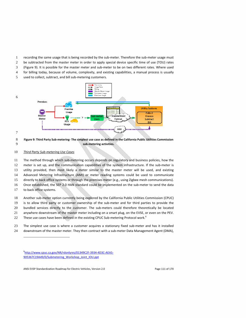
ANSI EVSP Standardization Roadmap for Electric Vehicles, Version 2.0 Page 111 of 170
recording the same usage that is being recorded by the sub‐meter. Therefore the sub‐meter usage must 1
be subtracted from the master meter in order to apply special device specific time of use (TOU) rates 2
(Figure 9). It is possible for the master meter and sub‐meter to be on two different rates. Where used 3
for billing today, because of volume, complexity, and existing capabilities, a manual process is usually 4
used to collect, subtract, and bill sub‐metering customers. 5
6
7
Figure 9: Third Party Sub‐metering‐ The simplest use case as defined in the California Public Utilities Commission 8 sub‐metering activities. 9
Third Party Sub‐metering Use Cases 10
The method through which sub‐metering occurs depends on regulatory and business policies, how the 11
meter is set up, and the communication capabilities of the system infrastructure. If the sub‐meter is 12
utility provided, then most likely a meter similar to the master meter will be used, and existing 13
Advanced Metering Infrastructure (AMI) or meter reading systems could be used to communicate 14
directly to back office systems or through the premises meter (e.g., using Zigbee mesh communications). 15
Once established, the SEP 2.0 HAN standard could be implemented on the sub‐meter to send the data 16
to back office systems. 17
Another sub‐meter option currently being explored by the California Public Utilities Commission (CPUC) 18
is to allow third party or customer ownership of the sub‐meter and for third parties to provide the 19
bundled services directly to the customer. The sub‐meters could therefore theoretically be located 20
anywhere downstream of the master meter including on a smart plug, on the EVSE, or even on the PEV. 21
These use cases have been defined in the existing CPUC Sub‐metering Protocol work.6 22
The simplest use case is where a customer acquires a stationary fixed sub‐meter and has it installed 23
downstream of the master meter. They then contract with a sub‐meter Data Management Agent (DMA), 24
6http://www.cpuc.ca.gov/NR/rdonlyres/01349C2F‐3934‐4D3C‐AEA5‐
905367C19A49/0/Submetering_Workshop_Joint_IOU.ppt
ANSI EVSP Standardization Roadmap for Electric Vehicles, Version 2.0 Page 112 of 170
who could also be the meter provider, to collect the data. The communication between the sub‐meter 1
and the third party could be proprietary or could be based on an existing or expected metering 2
communication standard (e.g., ANSI C12 developed by NEMA (ASC/C12), SEP 2.0). The DMA, who has 3
previously established a relationship with the billing agent, then provides them with the customer PEV 4
consumption data (in a standardized format) so they can subtract the usage from the premises usage, 5
apply tariffs, and complete the billing processes. Though simple enough in theory, additional 6
complications arise based on the location of the sub‐meter (EVSE, smart plug, PEV, mobile cordset), 7
number of sub‐meters and sub‐meter DMAs, regulatory structures (e.g., certification), system 8
requirements (e.g., transfer timing), and communication capabilities (e.g., data format). 9
These new types of metering and use cases create additional complexity including sub‐meter 10
measurement (accuracy), access, performance, security/privacy, and communications, for example, 11
mobile sub‐metering, which refers to sub‐meters within EVs or combined with 110V or 220V cord sets 12
that can be transported and exchanged. Pre‐authorization would be required if an EV consumed energy 13
at a visited premises but was to be billed to the owner’s home account. This pre‐authorization would 14
have to be on file with the utility to subtract the energy used by the EV from the bill of the visited 15
premises. Additionally, the vehicle must associate with that premises and both the vehicle’s ID and 16
premises meter or account ID must be communicated with the utility. This would involve local 17
association (e.g., PLC or HAN technology). If the vehicle is travelling outside of the territory for which it 18
has an associated service account, utilities will most likely have to share customer and consumption 19
information. Similar to premises meters, mobile metrology could be collected using either a proprietary 20
or standardized communication method (e.g., telematics, AMI, or SEP2.0 for utilities), depending on 21
regulatory and utility policies. 22
Standardization Activities 23
Two broad areas of standardization related to sub‐metering have been identified and are currently at 24
some stage of completion. The first is the standardized communications format necessary between the 25
third party DMA and the billing agent. The CPUC activities have identified the Energy Services Provider 26
Interface (ESPI) as a national standard that can be used for this interface. This work is ongoing in the 27
OpenADE working group, which is currently completing a Green Button Sub‐metering Profile of ESPI that 28
will include testing and certification. 29
Gap: Communication of standardized EV sub‐metering data. Standards are needed for communication 30
of EV sub‐metering data between third parties and service providers. 31
Recommendation: Complete Green Button Sub‐metering Profile of ESPI for communication of 32
standardized EV sub‐metering data, for example, between a third party and a billing agent (e.g., utility). 33
Priority: Near‐term. Potential Developer: OpenADE/NAESB. Grid Related: Yes. Status of Progress: 34
Green. Update: The roadmap version 1.0 text, gap statement, recommendation and potential 35
developers have been revised to be specific about communication of EV sub‐metering data between 36
third parties and service providers and to complete work on the Green Button Sub‐metering Profile of 37
ESPI. 38
ANSI EVSP Standardization Roadmap for Electric Vehicles, Version 2.0 Page 113 of 170
Besides the utility interface standard, requirements and guidelines related to the standardization of 1
these third party sub‐meters are being explored further by three separate activities discussed below: 2
NEMA, NIST, and the Smart Grid Interoperability Panel V2G Domain Expert Working Group (SGIP V2G 3
DEWG). 4
NEMA 5
NEMA has organized a working group (NEMA 5EVSE Submetering WG) that is developing a guide for 6
EVSE embedded metering and communication. The purpose of this document is to provide guidance for 7
EVSE applications that include an embedded meter incorporating a communication protocol for 8
monitoring or monitoring and control. Recognizing that many codes, standards and regulatory 9
documents relative to EVSE metering already exist, this guide will point to specific codes and standards 10
already in place that determine the requirements specific to meter accuracy and communication 11
protocols. Stakeholders expected to benefit from this document include EVSE manufacturers, utilities, 12
automakers, smart meter manufacturers, EV drivers, EVSE owners, and regulators. 13
The scope of the NEMA guide provides that the embedded meter may or may not be a “revenue grade” 14
meter. The document encompasses the North American types of meters that are emerging within EVSEs 15
including embedded meters. It is intended to address the different form factors, capabilities, 16
installations and certifications. The guide will also attempt to determine the optimal authority and 17
jurisdictional span for metering certification. The guide will recommend a tiered key functionality for 18
embedded meters including tamper resistance, accuracy, calibration, communication, security, and 19
reliability. An example of the proposed approach is the NEMA ratings for embedded meters similar to 20
NEMA enclosure ratings. The applicable EVSEs in the document include Level 1 and Level 2 (AC and DC). 21
NIST’s U.S. National Work Group on Measuring Systems for Electric Vehicle Fueling and Submetering 22
In August 2012, NIST formed the U.S. National Work Group on Measuring Systems for Electric Vehicle 23
Fueling and Submetering (USNWG EVF&S) to develop proposed requirements for commercial 24
electricity‐measuring devices (including those used in sub‐metering electricity at residential and 25
business locations and those used to measure and sell electricity dispensed as a vehicle fuel) and to 26
ensure that the prescribed methodologies and standards facilitate measurements that are traceable to 27
the International System of Units (SI). This work is not intended to address utility metering in the home 28
or business where the metered electricity is consumed by the end purchaser and that falls under the 29
authority of entities such as the local utility commission. 30
The USNWG EVF&S’s technical output may result in the revision of current standards or the 31
development of new standards for requirements and testing procedures for commercial devices and 32
systems used to assess fees and charges to consumers for electric vehicle fuel. The output of the 33
USNWG EVF&S will be submitted to be published in documents such as NIST Handbook 130 Uniform 34
Laws and Regulations in the Areas of Legal Metrology and Engine Fuel Quality; NIST Handbook 44 35
Specifications, Tolerances, and Other Technical Requirements for Weighing and Measuring Devices; the 36
NIST Handbook 105 Series for field standards; and NIST Examination Procedure Outlines. 37
ANSI EVSP Standardization Roadmap for Electric Vehicles, Version 2.0 Page 114 of 170
SGIP V2G DEWG 1
The SGIP V2G DEWG has initiated a Priority Action Plan to establish a Sub‐Meter Standards Working 2
Group consisting of representatives from NEMA, USNWG EVF&S, national labs, automakers, utilities, and 3
EVSE manufacturers to administer and coordinate the development of sub‐meter standards for mobile 4
and stationary applications. Presently, the requirements for standardization of sub‐meters are not well 5
defined nor understood by all involved parties. The primary elements to be addressed are access, 6
accuracy, form factor, tamper resistance, performance, reliability, data requirements, security, testing 7
and certification. The SGIP Priority Action Plan Sub‐Meter working group is to: coordinate the definition 8
of sub‐meter requirements, map the requirements to existing meter standards, engage the cognizant 9
organizations to address specified gaps in existing meter standards, and develop new standards if 10
deemed necessary. The resulting standards documentation will be evaluated for approval by the SGIP 11
for incorporation into the SGIP Catalog of Standards. 12
Gap: Standardization of EV sub‐meters. Standards for EV sub‐meters, including embedded sub‐meters, 13
need to be completed to address performance, security/privacy, access, and data aspects. 14
Recommendation: Develop standards or guidelines related to the functionality and measurement 15
characteristics of the new types of sub‐meters that are coming out for EVs, including embedded sub‐16
meters in the EVSE or EV. Such standards should address different form factors, capabilities, installation, 17
and certification. Priority: Near‐term. Potential Developer: NEMA, USNWG EVF&S. Grid Related: Yes. 18
Status of Progress: New gap/ Green. 19
20
Gap: Coordination of EV sub‐metering activities. Various existing activities (NEMA, USNWG EVF&S, SGIP 21
V2G DEWG) need to be coordinated as much as possible. 22
Recommendation: Organizations developing standards, guidelines or use cases related to EV sub‐23
metering should coordinate their activities in order to avoid duplication of effort, assure alignment, and 24
maximize efficiency. Priority: Near‐term. Potential Developer: NEMA, USNWG EVF&S, SGIP V2G DEWG. 25
Grid Related: Yes. Status of Progress: New gap / Green. 26
4.2.2.4 Cyber Security and Data Privacy 27
SAE J2931/7, Security for Plug‐in Electric Vehicle Communications, currently in development, is looking 28
to define use cases and security requirements for the digital communications and data in transit 29
between the following devices: 30
- Plug‐in Electric Vehicle (PEV) and the Energy Service Interface (ESI); 31
- PEV and the Electrical Vehicle Supply Equipment (EVSE); 32
- EVSE and the Energy Management System, and/or ESI; and 33
ANSI EVSP Standardization Roadmap for Electric Vehicles, Version 2.0 Page 115 of 170
- Wireless charging communication between the PEV and wireless charger. 1
It also looks at use cases and security requirements concerning protection of data at rest within the 2
devices. 3
ISO/IEC 15118‐1 includes a subsection on security but does not address things like how certificates can 4
be stored, how data can be compromised, etc. 5
The current version of NISTIR 7628, Guidelines for Smart Grid Cyber Security, Volume 2: Privacy and the 6
Smart Grid (published in August 2010, http://csrc.nist.gov/publications/nistir/ir7628/nistir‐7
7628_vol2.pdf), includes a use case relating to privacy and EVs which keys off of the OECD Privacy 8
Guidelines. NISTIR 7628, Volume 2, is in the process of being substantially reworked in light of SAE 9
J2836TM. 10
Gap: Cyber security and data privacy. There is a need for guidelines and standards to address cyber 11
security and data privacy concerns associated with PEVs and smart grid communications. 12
Recommendation: Complete work to develop SAE J2931/7, and to revise ISO/IEC 15118‐1 and NISTIR 13
7628, volume 2. Priority: Near‐term. Potential Developer: SAE, ISO/IEC JWG, NIST. Grid Related: Yes. 14
Status of Progress: New gap / Green. 15
4.2.2.5 Telematics Smart Grid Communications 16
Use cases are to be developed to determine whether Energy Service Provider requirements are not met 17
by existing standards and architectures. Among these might be aggregation control for ancillary services, 18
vehicle information for distribution load management, and access to dynamic consumer behavior data 19
(e.g., instantaneous usage, consumption usage, volts, amps, VAR, power factor, etc.). The use cases will 20
be defined in SAE J2836/5TM through mapping to existing use cases for J2836/1TM, J2836/3TM, and 21
existing standards such as OpenADR 2.0 to assess and identify any gaps in the function sets. 22
Gap: Telematics smart grid communications. There is a need to develop use cases related to non‐utility 23
aggregation control and vehicle information in order to assess the existing functionalities, and to 24
determine any missing requirements within the context of existing standards, Energy Service Provider 25
business requirements, and telematics networks to support smart grid load management. 26
Recommendation: Complete work to develop SAE J2836/5 TM. Priority: Near‐term. Potential Developer: 27
SAE. Grid Related: Yes. Status of Progress: New gap / Green. 28
4.2.3 Infrastructure Installation 29
4.2.3.1 Site Assessment / Power Capacity Assessment 30
The National Electrical Code® (NEC®) provides minimum requirements for performing site assessments, 31
specifically NEC® Articles 210, 215, and 220 contain rules that relate to calculations and loading of 32
services, feeders, and branch circuits in all occupancies. AC Level 1 and AC Level 2 EVSE are considered 33
ANSI EVSP Standardization Roadmap for Electric Vehicles, Version 2.0 Page 116 of 170
continuous loads with the maximum current expected to continue for 3 hours or more. Pursuant to a 1
Tentative Interim Amendment (TIA) to the 2011 NEC®, if an automatic load management system is used, 2
the maximum electric vehicle supply equipment load on a service or feeder shall be the maximum load 3
permitted by the automatic load management system. If there is no load management, then they must 4
be sized for 125% of the maximum current. Fast‐charging EV supply equipment operates for less than 3 5
hours but is calculated at 125% of the nameplate current rating. Section 625.14 of the NEC® contains 6
additional provisions related to the load calculations for EVSE. 7
In conducting a site/power capacity assessment for existing facilities (residential, commercial, and 8
industrial), the following needs to occur: 9
- Conduct site visit; 10
- Inventory electrical equipment; 11
- Interview the facility occupants to determine the cyclical daily and seasonal loading of the 12
facility; 13
- When available, review a minimum of 12 months of electric utility bills to determine the 14
maximum demand for incorporation into load calculations; and 15
- Verify by calculation the existing loads on the service or system. For commercial installations, 16
consideration for future expansion and multiple EVSE should be included in load calculations. 17
Involve electrical utility planners early in the process when planning EVSE for fleet applications. 18
Site Assessment Verifies Locations and Other NEC® Requirements 19
The site assessment is also required to verify acceptable location(s) of the EVSE and conformance with 20
the NEC® and other applicable codes such as the International Residential Code® for One‐ and Two‐21
Family Dwellings (IRC®), International Building Code® (IBC®), Americans with Disabilities Act (ADA) 22
requirements (ICC/ANSI A117), and any other state or local zoning regulations. Note that local codes and 23
regulations may be more restrictive than national codes and must be verified with the applicable 24
jurisdiction. This can be determined during the permitting process for installation. 25
Other NEC® Rules and Installation Standards 26
The NEC® also provides the minimum requirements for service equipment, overcurrent protection, 27
grounding and bonding, appropriate wiring methods, and locations or occupancy types that are often 28
determined as part of a site assessment. Branch circuit or feeder wiring method can vary depending on 29
the EVSE installation location. A National Electrical Installation Standard (NEIS) NECA 413, Standard for 30
Installing and Maintaining Electric Vehicle Supply Equipment (EVSE), provides detailed information 31
about performing site assessments and installation of EVSE in new and existing electrical systems. NECA 32
413 covers the following related to performing effective site assessments: 33
- Supply Equipment/Charging Power Selection: AC Level 1, AC Level 2, Fast Charging; 34
ANSI EVSP Standardization Roadmap for Electric Vehicles, Version 2.0 Page 117 of 170
- Charging Equipment (Type): Conductive, Inductive; 1
- Service or Power Capacity (load on new and existing systems or services); 2
- Electrical Load Calculations; 3
- Site Selection and Preparation; 4
- Zoning and Site Restrictions; 5
- Sites for Fleet Charging Installations; 6
- Energy Code Requirements; 7
- Mechanical Ventilation (where required); 8
- Electric Utility Interconnection Installation Requirements; 9
- Utility Interactive EVSE Installation; 10
- Special Metering or Special Metering Equipment Installation; and 11
- Time of Use or Off‐Peak Metering Installation(s). 12
Some specific installations under the exclusive control of an electric utility are excluded from the scope 13
of the National Electrical Code® (NEC®) and fall under the scope of ANSI C2, the National Electrical Safety 14
Code® (NESC®). These are generally locations where the utility‐owned installations are on legally 15
established easements or rights‐of‐way. The NESC® is a code that is primarily used for generation, 16
transmission, distribution, and metering of electrical energy. However, the National Electrical Code® 17
(NEC®) applies to some installations that are owned by electric utilities including utility owned office 18
buildings and garages. The addition of electric vehicles may necessitate the need for a utility 19
infrastructure upgrade to achieve an adequate power supply. 20
The site/power capacity requirements for EVSE connected to an electric service or other power source 21
are already well covered in the NEC®. The permit process usually captures any issues related to the site 22
as far as zoning or suitable locations for EVSE. 23
No gaps have been identified at this time with respect to this issue. 24
Harmonization Efforts 25
A harmonization assessment has been conducted examining NEC® Article 625, the Canadian Electrical 26
Code, and IEC 60364 to identify parallel sections which have already been harmonized and those which 27
may still need to be. This effort is nearly complete. 28
29
ANSI EVSP Standardization Roadmap for Electric Vehicles, Version 2.0 Page 118 of 170
4.2.3.2 EV Charging – Signage and Parking 1
Public Signage 2
The Manual on Uniform Traffic Control Devices (MUTCD) for Streets and Highways contains federal 3
regulations that govern the design and usage of traffic control devices. These are minimum standards 4
for use which means that states and local agencies can establish standards above the MUTCD 5
minimums. In April 2011, the U.S. Department of Transportation (DOT) Federal Highway Administration 6
issued an interim approval for the optional use of a General Service symbol sign that provides road users 7
direction to electric vehicle charging facilities that are open to the public.7 8
The U.S. Department of Energy’s Clean Cities program has been working with various stakeholders to 9
raise awareness of the importance of clear and consistent signage for EV charging. This includes: 10
working with agencies such as DOT, convening stakeholders to promote uniformity in way‐finding and 11
regulatory signage, identifying best practices and disseminating case studies on successful signage 12
implementation, and encouraging sound and strategic investments in increased signage to support the 13
deployment of EVs. 14
No gaps have been identified at this time with respect to this issue. 15
Parking Space Allocation 16
Currently, the model International Green Construction CodeTM (IgCCTM) has an elective provision 17
requiring that for covered buildings8 5 percent of, but not less than two, parking spaces shall be reserved 18
for low emission, hybrid and electric vehicles (IgCCTM, PV2, Sec. 403.4.2). There are no current standards 19
or model code provisions within either the IBC® or IgCCTM requiring EV only parking or charging. At some 20
point, this may be desirable. Recommendations for new code provisions would have to be made and 21
accepted as part of the normal code revision cycle. The state of California does have a law that governs 22
electric vehicle charging station parking. See also the discussion below on accessibility for persons with 23
disabilities to EVSE. 24
No gaps have been identified at this time with respect to this issue. 25
Harmonization Efforts 26
As urban planning is a localized activity, harmonization is generally not a relevant issue. 27
7 http://mutcd.fhwa.dot.gov/resources/interim_approval/ia13/
8 Generally, the IgCC
TM scope covers all commercial buildings, except residential buildings. The IgCC
TM applies to the
construction of all buildings, both old and new, except IRC® buildings, R‐3 occupancies, R‐2 and R‐4 occupancies 4
stories or less in height. These exceptions are regulated by ICC 700, the National Green Building StandardTM, where
the jurisdiction indicates so in Table 302.1.
ANSI EVSP Standardization Roadmap for Electric Vehicles, Version 2.0 Page 119 of 170
Conformance Programs 1
Most jurisdictions in the United States regulate parking issues at the local level without reference to 2
national standards. This is accomplished through ordinances and accompanying regulations including 3
various means of enforcement (mechanical and electronic), as well as civil and criminal requirements 4
and penalties. No gaps have been identified at this time. 5
4.2.3.3 Charging Station Permitting 6
Normally the installation of EVSE is governed under a construction permitting process of the applicable 7
authority having jurisdiction, which could be a state, city, county, town, or other municipality. Often the 8
local jurisdiction has knowledge of additional permits necessary and advises this during the initial 9
permitting application process. 10
Another condition that may necessitate additional permits for installing EVSE is when the equipment is 11
located in public right‐of‐ways. In these cases, a state, county, or city may require a right‐of‐way work 12
permit and inspection. There may also be right‐of‐way specifications by the permit‐issuing entity. 13
Airports, train stations, bus stations, and other public transit depots may have specific owner permits 14
that are required, in addition to the city, county, or state permit required for installation safety. 15
Residential Permitting: The primary purpose of the permitting process is to ensure an installation that is 16
safe from shock and fire hazards, as well as the potential for physical damage. EVSE installations are a 17
significant continuous duty load. Older homes may not have the capacity to safely supply the load. Even 18
some more modern homes with electric heating or air conditioning may be near their capacity limit. 19
The permitting process involves a review of the plans and an on‐site inspection to ensure compliance 20
with the requirements of the National Electrical Code® (NEC®), published by NFPA. The NEC® is widely 21
adopted, and is also referenced in the International Residential Code® for One‐ and Two‐Family 22
Dwellings (IRC®), published by ICC, that is used as the basis for regulation of residential buildings in all 50 23
states, at the state or local level. Provisions exist in the 2011 NEC® to cover EV charging systems and 24
their installation. The DOE Clean Cities program has published information which may be used as a 25
starting point for jurisdictions looking to establish permitting procedures for EVSE.9 26
Commercial/Public Permitting: The permitting process is also important for nonresidential installations. 27
Capacity of the electrical system is also a concern in these occupancies, particularly where there are 28
multiple EVSE that may be in use. Fire and shock hazards are a concern. There is also a higher risk of 29
vehicle damage and the potential for exposure to other hazards. 30
9 http://www.afdc.energy.gov/vehicles/electric_deployment.html
ANSI EVSP Standardization Roadmap for Electric Vehicles, Version 2.0 Page 120 of 170
The permitting process will verify electrical system capacity and compliance with the requirements of 1
the NEC®. The NEC® is referenced in the International Building Code® (IBC®), published by ICC, which is 2
used as the basis for regulation of commercial buildings and residential buildings of 4 stories or greater 3
in most states, at the state or local level. As noted, provisions exist in the NEC® to cover EV charging 4
systems and their installation. 5
There are some ongoing challenges associated with the permitting process. These include: varying costs 6
of permits by jurisdiction, length of the permitting process, and achieving widespread adoption of the 7
DOE template (for example, some state laws preclude its use and inspection processes may vary from 8
the template). These issues continue to be the subject of discussion among affected stakeholders. 9
No standards gaps have been identified at this time with respect to this issue. See, however, the 10
education and training section in relation to raising awareness among code officials regarding this issue. 11
Harmonization Efforts 12
No gaps have been identified at this time as permitting is a local issue and as such does not really lend 13
itself to harmonization. 14
Conformance Programs 15
In the U.S., conformance with electrical and building codes relies on three inter‐related mechanisms: 16
applicable installation codes and standards, product safety standards and certifications, and plan 17
approval and inspection. Each of the three components is considered critical to electrical and building 18
safety, and the system is compromised if one of the three is missing. While there may be some 19
variations in policies and procedures among jurisdictions, the three elements described are common to 20
most jurisdictions and have been largely successful in achieving safe buildings. While checklists can be of 21
assistance to jurisdictions in helping to assess conformance with common requirements, they should be 22
considered a starting point so that jurisdictions can address specific or unique concerns in their 23
inspection regimens. 24
No gaps have been identified at this time. 25
4.2.3.4 Environmental and Use Conditions 26
Product standards such as UL 2594, Standard for Electric Vehicle (EV) Supply Equipment, generally 27
anticipate maximum ambient temperatures of 40C, although higher limits may be declared by 28
manufacturers and validated in the testing. This is consistent with widespread use of a 40C default 29
ambient threshold for industrial and similar equipment. Product testing generally includes consideration 30
for lower ambient levels, such as ‐30C, for particular test conditions. 31
Exposure to the elements is generally addressed by established test methods, such as the NEMA 32
enclosure type designations and related testing. Environmental considerations are also addressed in UL 33
50E, Enclosures for Electrical Equipment, Environmental Considerations. 34

ANSI EVSP Standardization Roadmap for Electric Vehicles, Version 2.0 Page 121 of 170
Exposure to corrosive agents for EV infrastructure equipment is addressed in various ways by product 1
standards, generally in consideration of the degrading effects of exposure to the elements, anticipated 2
fumes or solvents, and/or anticipated compounds such as gasoline fuels that may be present in 3
vehicular locations. 4
Use of equipment, including electric vehicle supply equipment, in hazardous (classified) locations is 5
addressed by well‐established requirements. These requirements mitigate the potential fire or explosion 6
hazards by various strategies to minimize the risk of an electrical circuit from serving as a source of 7
ignition for the potentially hazardous gases, vapors, or other sources. The established requirements 8
include numerous product standards relevant to the use of the equipment in particular classified 9
locations, and installation requirements in Chapter 5 of the National Electrical Code®. 10
Electric vehicles will be exposed to many of the same hazards as conventionally powered vehicles. The 11
principal difference is that EVs are a source, as well as a user of large amounts of electrical energy. EVSE 12
installation must consider all of the potential environmental as well as occupancy exposures. For 13
example, in a parking garage, there may be more potential for exposure to vehicle impact damage. 14
Parking garages may be required to comply with NFPA 88A, Standard for Parking Structures, or with 15
Section 406 of the International Building Code® (IBC®), Motor Vehicle Related Occupancies. Which code 16
or standard applies depends on which code or standard the particular jurisdiction has adopted. 17
Another example would be that electric vehicles are likely to use automotive service stations. Parts of 18
these stations are considered to be hazardous locations in accordance with NFPA 30A, Code for Motor 19
Fuel Dispensing Facilities and Repair Garages, Article 514 of the National Electrical Code®, and Section 20
307 of the International Building Code® (IBC®). Exposure to this type of hazard will require the 21
compliance with additional requirements in Articles 500, 501, and 514 of the NEC® to ensure that EVSE 22
does not become an explosion hazard. 23
Other applicable hazards also need to be considered. Location of the EVSE installation away from 24
hazards is the primary means to minimize risk. 25
No gaps have been identified at this time with respect to this issue. 26
4.2.3.5 Ventilation – Multiple Charging Vehicles 27
Most batteries used in electric vehicles manufactured by major automakers do not emit hydrogen gas in 28
quantities that could cause an explosion. Preventive measures such as mechanical or passive ventilation 29
are not required. 30
SAE Standards 31
SAE International’s recommended practice SAE J‐1718, Measurement of Hydrogen Gas Emission from 32
Battery‐Powered Passenger Cars and Light Trucks During Battery Charging, can be used to assess 33
suitability for indoor charging. This standard includes provisions for tests during normal charging 34
operations and potential equipment failure modes. 35
ANSI EVSP Standardization Roadmap for Electric Vehicles, Version 2.0 Page 122 of 170
NEC® Code Provisions 1
Some electric vehicles will require ventilation because they use batteries that generate hydrogen. 2
Section 625.29(D) of the NEC® has requirements for ventilation for single and multiple vehicles, and 3
Section 625.15(B)&(C) provides ventilation labeling requirements for EVSEs. 4
ICC Code Provisions 5
The model International Residential Code® for One‐ and Two‐Family Dwellings (IRC®) has specific 6
requirements regulating ventilation requirements for “hydrogen generating and refueling operations.” 7
Such requirements could be referenced or modified for similar ventilation issues, should they exist with 8
respect to EV charging operations. The IRC® scope includes one and two family dwellings, as well as 9
multi‐family dwellings of three stories or less in height. 10
The model International Building Code® (IBC®) has provisions requiring a ventilation system in all 11
“Enclosed Parking Garages.” The ventilation system must meet requirements of the International 12
Mechanical Code® (IMC®), which is referenced in the IBC®. The IBC® scope includes all commercial 13
buildings, as well as all residential buildings of more than 3 stories in height. 14
No gaps have been identified at this time with respect to this issue. 15
Conformance Programs 16
Most jurisdictions currently issue permits and inspect parking garages through building code 17
enforcement permitting and inspection processes that are well‐established and well understood. No 18
gaps have been identified at this time with respect to this issue. 19
4.2.3.6 Guarding of EVSE 20
In general, available information with regards to guarding of EVSE is limited. NFPA 730, Guide to 21
Premises Security, addresses security in all occupancies from residential dwellings to large industrial 22
complexes. Provisions describe construction, protection, and occupancy features and practices intended 23
to reduce security risks to life and property. Specifically, Annex E is an informative annex which 24
discusses the placement/design of bollards. Another issue is when to design for physical protection as 25
opposed to designing for a break‐away scenario if a vehicle from a nearby roadway collides with the 26
EVSE. 27
Gap: Guarding of EVSE. There is a lack of standards that address charging station design with respect to 28
physical and security protection of the equipment. 29
Recommendation: Guidelines or standards relating to guarding of EVSE should be developed. Priority: 30
Mid‐term. Potential Developer: NFPA. Grid Related: No. Status of Progress: Unknown. Update: The 31
roadmap version 1.0 text and potential developers have been updated. NFPA has work on premises 32
security and, so, has been added as a potential developer. It does not appear that NHSTA has jurisdiction 33
in this area and neither it nor the American Association of State Highway and Transportation Officials 34
ANSI EVSP Standardization Roadmap for Electric Vehicles, Version 2.0 Page 123 of 170
(AASHTO) have developed guidelines or standards for guarding of EVSE. No other agencies or 1
organizations have been identified at this time that are working on this issue. 2
4.2.3.7 Accessibility for Persons with Disabilities to EVSE 3
Accessibility and compliance with requirements for accessibility in adopted building codes, and state or 4
federal accessibility requirements, i.e., the Americans with Disabilities Act (ADA) and Fair Housing Act 5
(FHA), is an issue for EVSE. According to the Electric Drive Transportation Association, the “ADA does not 6
specifically prescribe standards addressing the installation of charging infrastructure; however, it does 7
provide general guidance in sections 206, 208, 403.5 and 502 related to routes, clearances, and parking 8
spaces.”10 While some states have developed guidelines related to charging station accessibility, 9
enforcement rests with the local authority having jurisdiction. 10
There are two steps needed to address accessible EV parking and charging in standards and codes. The 11
first is to propose changes to a design standard (e.g., ICC A117.1) that addresses technical criteria for 12
how you design and build something to be accessible. The second is to propose changes to scoping 13
requirements in a relevant code, for example, the IBC®, IgCCTM, or International Zoning Code® (IZC®), for 14
when something must be accessible and the number that must be accessible. A submittal to revise any 15
code is premature without a reference to a design standard. Changes to ICC standards and codes must 16
come from outside parties; ICC staff cannot make such proposals. 17
Since EV charging stations will need to be available in both non‐accessible as well as accessible parking 18
spaces, a code change proposal should suggest both a requirement for a certain percentage of parking 19
spaces to have charging stations, including minimum numbers, as well as a percentage / minimum 20
number of accessible parking spaces to have charging stations. 21
The DOE Clean Cities program is an information resource for guidance on accessibility in relation to EVSE 22
installations. 23
Gap: Accessibility for persons with disabilities to EVSE. There is a lack of standards that address 24
charging station design with respect to accessibility for persons with disabilities to EVSE. 25
Recommendation: Guidelines or standards relating to accessibility for persons with disabilities to EVSE 26
should be developed. Priority: Mid‐term. Potential Developer: ICC (ICC A117.1 and IBC®, IgCCTM or IZC®). 27
Grid Related: No. Status of Progress: Yellow. Update: Additional text has been added to the roadmap 28
describing the two‐step process for addressing accessible EV parking and charging in relevant standards 29
10 http://goelectricdrive.com/Resources/Accessibility.aspx
ANSI EVSP Standardization Roadmap for Electric Vehicles, Version 2.0 Page 124 of 170
and codes including the ICC A117.1, IBC®, IgCCTM, and IZC®. Non‐accessible EV parking and charging also 1
is addressed in the roadmap text. These roadmap revisions were prompted in part because a proposal 2
to specify a required number of EV charging locations in the parking requirements of the 2015 IBC® was 3
rejected and no appeal or comments were subsequently filed. The proposal only applied to accessible 4
parking spaces; it did not impose a general requirement or reference any standard. The proposal could 5
be re‐submitted for the 2018 code cycle. Technical criteria supporting such a proposal could be provided 6
for in the A117.1 standard. 7
4.2.3.8 Cable Management 8
Functional management of EV cables in public parking spaces is not specifically addressed by codes or 9
standards. 10
EVSE standards, including ANSI/UL 2251, the Standard for Safety for Plugs, Receptacles and Couplers for 11
Electric Vehicles, and the National Electrical Code®, contain requirements for breakaway protection of 12
cables. 13
ANSI/UL 355, the Standard for Safety of Cord Reels, covers cord reels for general use, as well as special‐14
use cord reels intended to be mounted on or in electrical utilization equipment such as appliances or 15
similar equipment. 16
Section 406 of the IBC® addresses Motor‐Vehicle‐Related Occupancies, with 406.2 addressing parking 17
garages; however, cable management is not specifically addressed. 18
Security of EVSE cables, including means to discourage theft of copper cables from EVSE, is not 19
specifically addressed at this time. Attempted theft of EVSE cables may also lead to potential safety 20
hazards. 21
Gap: Cable management. There is a lack of standards or code provisions that address functional 22
management of EV cables in public parking spaces. 23
Recommendation: Guidelines or standards relating to EVSE cable management should be developed. 24
Priority: Mid‐term. Potential Developer: UL, NFPA. Grid Related: No. Status of Progress: Green. 25
4.2.3.9 EVSE Maintenance 26
NECA 413, a national electrical installation standard (NEIS), provides information with regards to 27
maintaining EVSE. Specifically, Chapter 7 discusses maintenance in accordance with manufacturers’ 28
recommendations and provides guidelines for the care of EVSE, including periodic inspections for wear, 29
damage, and vandalism, as well as cleaning. 30
NFPA 70B, Recommended Practice for Electrical Equipment Maintenance, applies to preventive 31
maintenance for electrical, electronic, and communications systems and equipment. Systems and 32
equipment covered are typical of those installed in industrial plants, institutional and commercial 33
ANSI EVSP Standardization Roadmap for Electric Vehicles, Version 2.0 Page 125 of 170
buildings, and large multifamily residential complexes. NFPA 70B is not intended to duplicate nor 1
supersede manufacturer instructions for maintenance. 2
No gaps have been identified at this time with respect to this issue. 3
4.2.3.10 Workplace Safety Installation 4
There are multiple published standards and codes that include general and specific requirements for 5
safety in the workplace. The process of installing and maintaining EVSE must include application and 6
implementation of all workplace safety rules and specifically electrical workplace safety requirements as 7
provided in NFPA 70E‐2012, Standard for Electrical Safety in the Workplace. The U.S. Government 8
includes in the Code of Federal Regulations minimum requirements for workplace safety. 9
Minimum safety requirements for General Industry are provided in Part 1910, Occupational Safety and 10
Health Administration (OSHA) Standards Subpart S – Electrical. Subpart S includes general information, 11
design safety standards for electrical systems, safety‐related work practices, safety‐related maintenance 12
requirements, safety requirements for special equipment, definitions, and reference documents in 13
Appendix A. Minimum safety requirements for electrical construction are provided in Part 1926, OSHA 14
Subpart K – Electrical. Subpart K includes general information, installation safety requirements, safety‐15
related work practices, safety‐related maintenance and environmental considerations, safety 16
requirements for special equipment, and definitions. 17
No gaps have been identified at this time with respect to this issue. 18
4.3 Support Services Domain 19
4.3.1 Education and Training 20
Standards and education and training are important elements needed to ensure the safety and security 21
of electric vehicle owners and those who service the vehicles or respond to vehicle emergencies, and to 22
ensure safe EVSE installations, and consistency of information. 23
Much of the information needed by personnel who respond to emergencies or service EVs and 24
associated equipment is contained in original equipment manufacturer (OEM) or other manufacturer 25
information. There are standards for professional qualifications for rescue technicians and incident 26
managers (NFPA 1006 and 1026) but these cover generalized skills and safe methodologies without 27
getting into the specifics of vehicles or equipment. 28
4.3.1.1 Electric Vehicle Emergency Shut Off – High Voltage Batteries, Power Cables, Disconnect 29
Devices; Fire Suppression, Fire Fighting Tactics and Personal Protective Equipment 30
SAE J2990, Hybrid and EV First and Second Responder Recommended Practice, published in November 31
2012, provides a flow chart process to assess issues with the vehicle and battery. SAE J2990 also 32
provides recommendations for vehicle identification, high voltage disabling and critical items to be 33
summarized from emergency response guides (ERGs) provided by vehicle manufacturers and others. 34
ANSI EVSP Standardization Roadmap for Electric Vehicles, Version 2.0 Page 126 of 170
OEMs will be encouraged to reference SAE J2990 when creating industry design standards. High voltage 1
cabling in EVs is unlikely to become standardized in terms of location or routing. The routing of EV cables 2
is documented in shop manuals and ERGs. It is important that OEMs specify in their ERGs the location of 3
EV battery and disconnect devices and proper procedures/sequencing to shut off power to the vehicle, 4
and provide the same data to other ERG developers. 5
In May 2012, NFPA held a workshop on emergency responder personal protective equipment (PPE) for 6
hybrid and electric vehicles.11 The workshop brought together emergency responders and other 7
stakeholders to develop guiding principles and recommended action steps to address the proper PPE for 8
emergencies involving hybrid or electric vehicles, with a focus on minimizing the risk to emergency 9
responders due to hazards involving electrically energized equipment. The recommendations from this 10
workshop served as input to the development of SAE J2990. 11
NFPA’s Fire Protection Research Foundation, in partnership with the Auto Alliance, DOE and NHTSA, has 12
created a Technical Advisory Panel to research and develop best practices for fire suppression and fire 13
fighting tactics for incidents involving electric vehicle batteries. The results of this work are expected by 14
the third quarter of 2013 and may inform future revisions of SAE J2990 as well as NFPA 1971, Standard 15
for Protective Ensembles for Structural Fire Fighting and Proximity Fire Fighting; NFPA 1951, Standards 16
for Protective Ensembles for Technical Rescue Incidents; and NFPA 1999, Standard for Protective 17
Clothing for Emergency Medical Operations. 18
Partial Gap: Electric vehicle emergency shut off – high voltage batteries, power cables, disconnect 19
devices; fire suppression, fire fighting tactics and personal protective equipment. Standards / 20
guidelines are needed so that emergency responders can safely manage emergency events involving 21
electric vehicles. 22
Recommendation: Develop standards / guidelines so that emergency responders can quickly and easily 23
recognize high voltage batteries and power cables, operate disconnect devices, avoid electrical shock 24
hazards, and safely shut off power to an electric vehicle following an incident. Consider the need for 25
further standardization work with respect to fire suppression, fire fighting tactics, and personal 26
protective equipment, based on the results of research underway by NFPA’s Fire Protection Research 27
Foundation in partnership with others. Priority: Near‐term. Potential Developer: NFPA, SAE, ISO, IEC. 28
Grid Related: No. Status of Progress: Green. Update: With the publication of SAE J2990, the partial gap 29
identified in version 1.0 of this roadmap with respect to vehicle emergency shut off largely has been 30
addressed. In this version 2.0, the text, gap statement and recommendation have been substantially 31
modified to more broadly capture the scope of safety concerns facing emergency responders including 32
the possibility that additional standardization work may be needed with respect to fire suppression, fire 33
fighting tactics and personal protective equipment. 34
11 http://www.nfpa.org/assets/files//Research%20Foundation/EVPPEWorkshopPart1.pdf.
ANSI EVSP Standardization Roadmap for Electric Vehicles, Version 2.0 Page 127 of 170
Harmonization Efforts 1
CEN/CENELEC in their October 2011 report recommended increased efforts to ensure emergency 2
services are able to respond appropriately with respect to battery hazards caused by the use of electric 3
vehicles, mechanical impact to the batteries, and exposure of batteries to fire or water. The report also 4
noted that there is no unified language for safety labeling regarding EV batteries. The EU recognizes the 5
need to standardize labels and graphics for the protection of first responders to deal with incidents, but 6
no appropriate standards now exist in Europe. 7
4.3.1.2 Labeling of EVSE and Load Management Disconnects for Emergency Situations 8
General safety labeling of residential/commercial/public EVSE is covered under UL 2594 and UL 2202. 9
However, the standards do not specifically address disconnecting the devices in emergency situations 10
when a vehicle is connected to the EVSE and where a load management system is involved. 11
Where load management equipment is independent of the EVSE, then NFPA 70®, the National Electrical 12
Code®, applies. NEC® Article 625 contains the requirements for installing EV charging stations and would 13
be an ideal repository for language related to graphical symbols and color‐coding to identify load 14
management equipment and disconnects in emergency situations. 15
Gap: Labeling of EVSE and load management disconnects for emergency situations. Standards are 16
needed to address labeling of EVSE and load management disconnects for emergencies. 17
Recommendation: Develop standards to address graphical symbols and warning labels on EVSE as well 18
as disconnect instructions for emergency situations. Amend NEC® Article 625 to include requirements 19
for graphical symbols and color‐coding of load management equipment and disconnects for emergency 20
situations. Priority: Near‐term. Potential Developer: UL, NEMA, NFPA, SAE, ISO, IEC. Grid Related: No. 21
Status of Progress: Unknown. Update: The roadmap version 1.0 text, gap statement and 22
recommendation have been clarified to address labeling for emergency situations. UL and NEMA have 23
been added as potential developers. 24
4.3.1.3 OEM Emergency Response Guides 25
ERGs written by the OEMs are more abridged than shop and owner’s manuals and can be a valuable 26
resource to emergency responders, though the amount of information is still lengthy and in non‐27
standard formats across OEMs. NFPA has compiled the most crucial OEM information in their EV/Hybrid 28
ERGs into a single database available in both standardized electronic and print formats for use by 29
emergency responders and others as a quick reference on‐scene guide. Manufacturers’ labels and 30
symbols are replicated, but once these are also standardized the database of ERGs will utilize the 31
universal symbols. NFPA also makes individual OEM ERGs available online in PDF format at 32
http://www.evsafetytraining.org/Resources/Auto‐Manufacturer‐Resources.aspx. 33
ANSI EVSP Standardization Roadmap for Electric Vehicles, Version 2.0 Page 128 of 170
The previously mentioned May 2012 NFPA workshop included a recommendation to “continue efforts 1
to standardize vehicle response guide information, including universal content, style and format, to 2
facilitate universal implementation among emergency responders.” 3
No gaps have been identified at this time with respect to this issue. 4
4.3.1.4 Electrical Energy Stranded in an Inoperable RESS; Battery Assessment and Safe Discharge 5
Following an Emergency Event 6
The issue of stranded energy in an inoperable battery is being considered in SAE J3009, Stranded Energy 7
– Reporting and Extraction from Vehicle Electrochemical Storage Systems, now under development. The 8
intent of this document is to consider the type of information reported by the battery management 9
system (BMS) and recommended discharge level dependent on a collision or vehicle fire. The document 10
does not describe how the energy should be extracted. 11
In parallel, NHTSA and Argonne National Laboratory have started a project to develop safe assessment, 12
architecture and discharge procedures to extract stranded energy from high‐voltage vehicle batteries. 13
The purpose is to reduce the risk of fire or electrical injury associated with stranded energy in an 14
“accident‐compromised” rechargeable energy storage system (RESS). The project will examine the range 15
of conditions that may make the RESS inoperable through the life of the vehicle, including crash 16
incidents and exposure to fire. The project’s deliverables include defining a common interface port(s) to 17
support diagnostic assessment and discharge capability to an RESS mounted in a vehicle. In addition to 18
providing information on the condition / state of the battery, this may be a manual service disconnect. 19
The research project will last until 2014. 20
The SAE J2990 task force is not addressing the issue of stranded energy. 21
Gap: Electrical energy stranded in an inoperable RESS. Standards to enable common method 22
assessment of RESS condition and stability, and removal of the energy stranded in an inoperable RESS, 23
are needed to increase the safety margin to persons who may become exposed to the device in an 24
inoperable state for various reasons and conditions during the RESS life cycle. 25
Recommendation: Carry out research to independently identify a solution set to the issue of electrical 26
energy stranded in a damaged or inoperable RESS. Complete work on SAE J3009 to address a similar 27
scope. Priority: Near‐term. Potential Developer: SAE, NHTSA/Argonne NL. Grid Related: No. Status of 28
Progress: New gap / Green. 29
30
Gap: Battery assessment and safe discharge following an emergency event. There do not appear to be 31
standards addressing the assessment of battery stability and the need for safe discharge of EV batteries 32
following an emergency event. 33
Recommendation: Standards and/or guidelines to assess battery stability and the need for safe 34
discharge following an emergency event are needed to identify safe practices for performing such 35
ANSI EVSP Standardization Roadmap for Electric Vehicles, Version 2.0 Page 129 of 170
assessment and discharge and what training, equipment and personal protective equipment may be 1
required. The research on stranded electrical energy underway at NHTSA/Argonne NL is a first step 2
before developing such guidelines. Priority: Near‐term. Potential Developer: SAE, NHTSA/Argonne NL, 3
NFPA. Grid Related: No. Status of Progress: Not started. Update: The roadmap version 1.0 gap 4
statement and recommendation have been modified to include an assessment of battery stability. 5
Emergency responders are no longer identified as the specific user of battery discharge procedures since 6
second responders (tow operators, roadside assistance) and OEM representatives also may need such 7
training. The development of such procedures is now described as contingent upon research underway 8
by NHTSA / Argonne National Laboratory on stranded energy. Argonne and NFPA have been added as 9
potential developers. Text regarding safe battery recharge in emergencies has been removed and a new 10
roadmap section on Disaster Planning / Emergency Evacuations Involving Electric Vehicles has been 11
added to separately address that concern. 12
4.3.1.5 Disaster Planning / Emergency Evacuations Involving Electric Vehicles 13
There do not appear to be any standards or guidelines in place that address disaster planning in terms of 14
the need for quick recharging of EVs during emergency evacuation situations. While technically that may 15
suggest a gap, the same can be said with respect to refueling gas powered vehicles under such 16
conditions. In either case, a vehicle would need to be towed if it could not leave the road under its own 17
power. There is no other readily apparent solution. As this issue initially was raised by a Federal 18
Emergency Management Agency (FEMA) representative, FEMA is invited to further consider planning for 19
such scenarios. 20
No gap has been identified at this time. 21
4.3.1.6 Workforce Training 22
Emergency First Responder Training 23
NFPA’s Electric Vehicle Safety Training Project, funded by the U.S. Department of Energy and NFPA, is a 24
nationwide program to help firefighters, law enforcement officers, emergency medical services and 25
other first responders prepare for the growing number of hybrid and electric vehicles in the United 26
States. This program provides information and materials necessary to safely respond to emergency 27
situations involving advanced hybrid and electric vehicles on the road today. The training is designed to: 28
create awareness of unique emergency response needs for electric vehicles; drive awareness of the 29
availability of training modules and reference materials; remove concerns about the inherent safety of 30
electric vehicles and the ability to safely respond to emergency situations; and reassure the public that 31
trained first responders know what to do in emergency situations. 32
Key topics of NFPA’s training include: 33
- Overview of the EV electrical and safety systems; 34
- Identification of electric and hybrid vehicles; 35
ANSI EVSP Standardization Roadmap for Electric Vehicles, Version 2.0 Page 130 of 170
- Immobilization process; 1
- Electrical disabling procedures; 2
- EV extrication awareness, including high‐strength steel; 3
- Vehicle fire recommended practices; 4
- Emergency operations (battery fire, submersion); and, 5
- New challenges presented by vehicle charging stations and infrastructure. 6
NFPA’s web portal, www.EVsafetytraining.org, serves as a central repository for all EV safety information 7
for first responders. This website hosts training, videos, and simulations; includes an events calendar, 8
blogging, and news; and has a separate area for each auto manufacturer’s safety information. 9
NFPA’s training is provided via the following platforms: 10
- Train‐the‐Trainer Classroom course: An 8‐hour “Train the Trainer” Emergency Responder course 11
that covers the breadth of the program, along with strategies and learning objectives needed to 12
train a group of first responders. Currently being achieved through a partnership with the North 13
American Fire Training Directors, upon completion, attendees are capable of delivering the 14
program to their own agency/department. 15
- EV Safety Training Classroom Course: A 4 hour face‐to‐face instructor‐led program for 16
firefighters, and a 3 hour face‐to‐face instructor‐led program for law enforcement and 17
emergency medical services, that provides instruction on how to respond to EV incidents. 18
- Online Self‐Paced Study Course: An online, self‐paced web version, complete with video, 19
animations, simulations, data review exercises, and a final scenario room activity. A certificate is 20
mailed to the user following successful completion of the course. 21
- Vehicle Specific Online Training: Chevrolet Volt Electric Vehicle safety training has been 22
developed and released for the benefit of emergency responders on NFPA’s EV web portal, with 23
future model specific online training being released during the first quarter of 2012. 24
- Emergency Field Guide: This guide is a quick reference manual compiled from the 25
manufacturers’ emergency response guides, which contains the vital hybrid and electric vehicle 26
safety information for a first responder on each make and model of hybrid or electric vehicle. 27
This guide includes descriptions, diagrams, and locations of key high voltage EV components, as 28
well as vehicle power down and emergency procedures in order to successfully identify, 29
immobilize, and disable a hybrid or electric vehicle. This guide will be available in published and 30
online formats. 31
Several first responder agencies have reported utilizing the training provided by vehicle manufacturers 32
and other training consortiums. Law enforcement agencies have reported a need for increased access to 33
ANSI EVSP Standardization Roadmap for Electric Vehicles, Version 2.0 Page 131 of 170
first responder specific training. Law enforcement and emergency medical services need access to 1
responder safety training designed for their respective roles but enabled to integrate with training of 2
other responders to ensure efficient emergency operations. 3
Standards developing organizations can and should continue to foster such multi‐discipline input into 4
the development of standards and training programs regarding electric vehicles by including these 5
perspectives on appropriate technical and standards development committees. 6
No gaps have been identified at this time with respect to this issue. 7
Harmonization Efforts 8
In contrast to the U.S., there is no centralized training portal for electric vehicle responder safety in 9
Europe. Additionally, while the U.S. has developed a unified approach, where federal regulatory 10
agencies, vehicle and charging station manufacturers, standards organizations and the first responder 11
community have partnered to participate in the training and standards development process, no such 12
partnership has evolved in the EU. 13
Second Responder/Normal Operations Training Programs 14
Organizations like the National Institute for Automotive Service Excellence (ASE), the American 15
Automobile Association (AAA), and the Towing and Recovery Association of America Inc. (TRAA) have in 16
place training programs and certifications for their technicians who perform service functions on electric 17
vehicles. There does not appear to be a significant call for new training and/or certification programs at 18
this time. 19
EVSE Installer and Inspector Training 20
EVSE installations must comply with local, state, and national codes and regulations. The installation 21
process typically requires obtaining an electrical installation permit from local authorities, the use of a 22
licensed contractor for the actual installation, and a final electrical review by a certified electrical 23
inspector. 24
Article 625 of the National Electrical Code® (NEC®) sets forth installation safety requirements for typical 25
hard‐wired connections of EVSE, addressing wiring methods, equipment construction, control and 26
protection, and equipment locations. 27
In order to support the build out of charging infrastructure for EVs nationally, a steadily expanding pool 28
of qualified electrical installers and inspectors for EVSE is required. 29
The National Electrical Contractors Association (NECA) Workshop on Managing Electric Vehicle Supply 30
Equipment (EVSE) – Electrical Contractors is a course that reviews necessary steps that must be 31
performed to ensure system capacity of electrical power sources and service equipment and safe 32
installation of EVSE branch circuits and feeders. It includes a review of applicable rules in the NEC® that 33
must be applied to EVSE installations, including what constitutes qualifications of contractors and 34
ANSI EVSP Standardization Roadmap for Electric Vehicles, Version 2.0 Page 132 of 170
installers to perform EVSE installations. In addition to the minimum safety installation requirements of 1
the NEC®, safe work practices and applicable workplace safety requirements are reviewed. Applicable 2
performance and quality installation standards are integrated into this training program. Compliance 3
with regulatory agencies is also reviewed specifically as it relates to required work permits, inspections, 4
and approval of EVSE or vehicle charging equipment installations. The International Association of 5
Electrical Inspectors (IAEI) has partnered with NECA to develop the EV training that NECA has been 6
offering its chapters. This information is available to IAEI to develop training for inspectors and installers, 7
but to date has not been fully developed. Upon completion, it is expected to provide 1‐2 hours of 8
training but be more NEC® Article 625 oriented, somewhat akin to an electrical check list. 9
The Electric Vehicle Infrastructure Training Program (EVITP) – Electrical Workers is a 14‐18 hour class 10
which comprehensively addresses the requirements, regulations, products and strategies which will 11
enable electrical contractors and electricians to master successful, expert, and professional customer 12
relations, installation, and maintenance of EV and PHEV infrastructure. Upon completion of this class, 13
participants gain thorough knowledge and practical application of all covered EV infrastructure subjects 14
including the critical areas of customer experience, protection of utility systems, and vehicle charging 15
technical applications. 16
Additionally, Underwriters Laboratories, Inc. has developed a short (2.5 hr) e‐learning course on Electric 17
Vehicle Charging Station Installation for qualified electricians. 18
Charging Station Permitting 19
In addition to the model EVSE permitting template described earlier, the DOE Clean Cities program has 20
put together an EVSE 101 video that includes information for electrical installers and inspectors. DOE 21
funded projects are also exploring regional planning and workplace charging. The availability of this 22
information needs to be made widely and easily accessible to electrical installers and inspectors in 23
advance of when they find themselves faced with a potential EV charging station installation/permit 24
application. It also needs to be promoted in publications and websites that are regularly read or visited 25
by both the installer community and code officials (electrical, building and/or fire inspector). It is also 26
important to raise awareness with architects, community planners, land use planners, zoning officials, 27
and other authorities having jurisdiction over plans review of commercial real estate developments and 28
large residential track developments, as the involvement of these individuals will be critical to the future 29
growth and development of EVSE installations. 30
Partial Gap: Workforce Training – Charging Station Permitting. From a training perspective, there may 31
be a need to assemble and promote a “Code Official Toolkit” related to EVSE permitting. 32
Recommendation: Develop a Code Official Toolkit on EVSE permitting that includes, among other things, 33
the DOE permit template, EVSE 101 video, and an FAQ document for code officials that explains, for 34
example, the importance of safe and code‐compliant EV charging station installation requirements, and 35
relevant safety training programs. Consider creating a brief article that would highlight this issue and the 36
Toolkit as resources to run in appropriate association newsletters to increase awareness of resources 37
ANSI EVSP Standardization Roadmap for Electric Vehicles, Version 2.0 Page 133 of 170
available to installers, inspectors and other authorities having jurisdiction. Priority: Near‐term. Potential 1
Developer: DOE, ICC, NECA, IAEI, NFPA. Grid Related: No. Status of Progress: New gap / Green. 2
College and University Programs 3
As electric vehicle use increases, institutions of higher learning are beginning to address occupational 4
needs with education and training programs. Many of these programs are taking advantage of DOE 5
funding designed to increase adoption of electric vehicle technology. Programs vary from skill level 6
training for those repairing and maintaining electric vehicles and charging equipment, to engineering 7
programs for the next generation of designers. 8
The following educational institutions are known to offer electric vehicle training programs. 9
- J. Sargeant Reynolds Community College: The J. Sargeant Reynolds Community College in 10
Virginia is currently developing a career studies certificate in advanced automotive technologies 11
for electric vehicles. The courses include instruction on electric vehicles, plug‐in hybrid electric 12
vehicles, fuel cell electric vehicles, and control electronics. 13
- Purdue University: Purdue University is currently working with a group of other universities to 14
develop over 30 courses supporting electric vehicle technology and workforce needs. These 15
courses support two and four year students and certificate and workforce development 16
programs. 17
- University of Central Missouri: The automotive technology management program at the 18
University of Central Missouri proposes to develop a new certificate program for non‐degree 19
seeking individuals interested in advanced vehicle systems including electric vehicles, plug‐in 20
hybrid electric vehicles, fuel cell electric vehicles, and other future technologies. The possibility 21
of developing this program into a minor is also being examined by the university. In addition, 22
materials from this program can be condensed and adapted for outreach to community colleges 23
and OEM partners. The certificate program will consist of six courses with all but the basic 24
electronics course being taught by faculty holding the Automotive Service Excellence (ASE) 25
master certification. 26
- University of Michigan, Ann Arbor: The University of Michigan offers undergraduate and 27
graduate courses and degree programs related to electrified vehicles, with all of them targeting 28
regular B.S., M.S and M.Eng. degrees (i.e., engineering students or professional engineers). 29
Partial Gap: Workforce Training – College and University Programs. Identified higher education 30
programs related to electric vehicles do not appear to cover some issues that relate to charging 31
infrastructure development such as land use, community planning, and architecture. 32
Recommendation: Develop higher education programs focused on electric vehicle charging 33
infrastructure development from the standpoint of land use, community planning and architecture. 34

ANSI EVSP Standardization Roadmap for Electric Vehicles, Version 2.0 Page 134 of 170
Priority: Mid‐term. Potential Developer: Colleges and Universities. Grid Related: No. Status of Progress: 1
New gap / Green. 2
3
4
ANSI EVSP Standardization Roadmap for Electric Vehicles, Version 2.0 Page 135 of 170
5. Summary of Gap Analysis 1
Priority: Near‐term (0‐2 yrs); Mid‐term (2‐5 yrs); Long‐term (5+ yrs). 2
Status of Progress on Gaps: Closed (completed), Green (moving forward), Yellow (delayed in progressing), Red (at a standstill), Not started, Unknown, or New Gap (for roadmap version 2.0). 3
Roadmap Issue Section / page Gap Recommendation Priority
Potential Developer
Grid Related
Status of Progress
1.
Terminology 4.1 / 68 Terminology. There is a need for consistency with respect to electric vehicle terminology
Complete work to revise SAE J1715. Update: SAE J1715 is still in revision and is targeted for publication in the Spring of 2013. Mid‐term SAE, ISO No Green
2.
Power Rating Methods 4.1.1.1 / 69
Power rating methods. It was noted in roadmap version 1.0 that standards for electric vehicle power rating methods are still in development.
Complete work to develop SAE J2907 and J2908. Update: With respect to the roadmap version 1.0 gap, work on the power rating method standards SAE J2907 and J2908 has been canceled because of resource issues. It will be re‐opened under a new J number at a future date yet to be determined. Mid‐term SAE No Red
3.
Functional Safety in the Charging
System 4.1.1.2/ 72
Functional safety in the charging system. Potential faults in the charging system, both on‐board and off‐board, are the subject of NHTSA sponsored research and may need to be addressed in future rulemaking and/or standardization.
Future NHTSA rulemaking and/or revisions to SAE J2929 should consider the results of the DOT/NHTSA‐funded SAE Cooperative Research Project with respect to fault events in the charging system which could lead to overcharging. Update: The roadmap version 1.0 gap statement and recommendation have been updated to note NHTSA‐funded research, that the issue may be with the charging system rather than the battery, and that NHTSA rulemaking may result. NHTSA has been added as a potential developer and the priority level has been changed from mid‐term to near‐term. Recent updates to SAE J2929 do not address charging system failure; rather, they relate to electromagnetic compatibility (EMC) to ensure the safety functions of the battery are not impacted. Near‐term NHTSA, SAE No Green
4.
Delayed Battery Overheating
Events 4.1.1.2 / 73 Delayed battery overheating events. The issue of delayed battery overheating needs to be addressed.
Address the issue of delayed battery overheating events in future rulemaking and/or revisions of SAE J2929 based on the results of the DOT/NHTSA‐funded SAE Cooperative Research Project. Update: The roadmap version 1.0 recommendation Near‐term NHTSA, SAE No Yellow
ANSI EVSP Standardization Roadmap for Electric Vehicles, Version 2.0 Page 136 of 170
Roadmap Issue Section / page Gap Recommendation Priority
Potential Developer
Grid Related
Status of Progress
has been updated to note NHTSA‐funded research which may result in future rulemaking. NHTSA has been added as a potential developer. Version 2 of SAE J2929 has been published. However, the topic of delayed battery overheating events is not addressed in this revision; it is pending the results of the NHTSA sponsored research.
5.
Battery Testing ‐ Performance and
Durability 4.1.1.3 / 73
Battery performance parameters and durability testing. There is a need for further work on EV battery performance parameters and environmental durability test requirements.
Complete work on SAE J1798 and if possible consider harmonization with ISO 12405‐2. Update: There is not a lot of progress to date on SAE J1798. Mid‐term SAE, ISO No Yellow
6.
Battery Storage 4.1.1.4 / 74
Safe storage of lithium‐ion batteries. At present, there are no published standards addressing the safe storage of lithium‐ion batteries specifically, whether at warehouses, repair garages, recovered vehicle storage lots, auto salvage yards, or battery exchange locations.
A standard on safe storage practices for EV batteries must be developed, addressing both new and waste batteries and the wide range of storage situations that may exist, including when the batteries are separated from their host vehicle. Update: Roadmap version 1.0 gap statement has been modified to say there are no published standards addressing safe storage. IEC 62840 and the research project of the NFPA’s Fire Protection Research Foundation are noted in the text. Near‐term
SAE, NFPA, ICC, IEC/TC 69 No Green
7.
Battery Packaging, Transport and
Handling 4.1.1.4 / 75
Packaging and transport of waste batteries. Current standards and regulations do not adequately cover transportation aspects of waste batteries (damaged, aged, sent for repair, end‐of‐life) in terms of packaging, loading limitations, combination with other dangerous goods on same transport, etc.
There is a need for a harmonized approach toward communication, labeling, packaging restrictions, and criteria for determining when a battery is waste. Update: The UN SCOE was added as a potential developer as there is a proposal before it. Near‐term
UN SCOE on the Transport of Dangerous Goods, ISO/TC 22/SC21, SAE or UL No Green
8.
Battery Packaging, Transport and
Handling 4.1.1.4 / 75
Packaging and transport of batteries to workshops or battery swapping stations. Unloading a battery in a battery swapping station is extremely challenging with the original packaging used for dangerous goods transportation. There is a need for standards for intermediate packaging to cover transport to battery swapping stations.
Intermediate packaging is required between the import location of the battery and battery swapping stations and needs to be standardized around geometry, safety and matching to UN packaging requirements. Mid‐term
ISO/TC 22/SC21, SAE or UL. No Not started
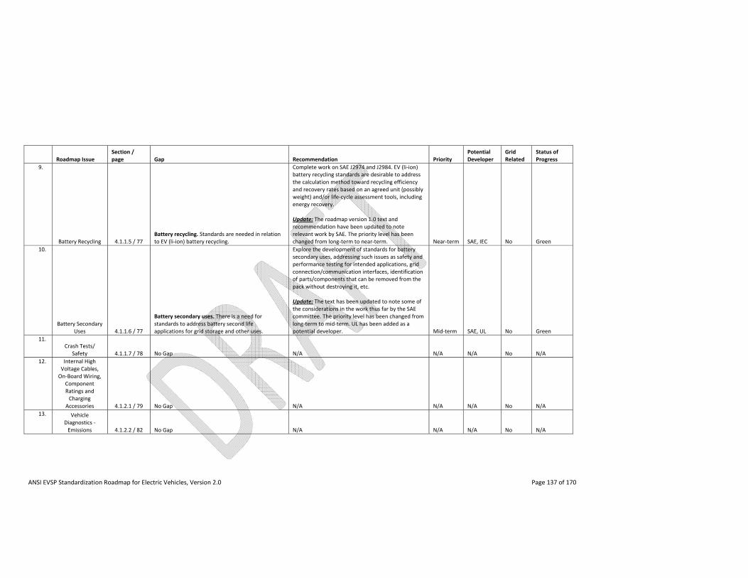
ANSI EVSP Standardization Roadmap for Electric Vehicles, Version 2.0 Page 137 of 170
Roadmap Issue Section / page Gap Recommendation Priority
Potential Developer
Grid Related
Status of Progress
9.
Battery Recycling 4.1.1.5 / 77 Battery recycling. Standards are needed in relation to EV (li‐ion) battery recycling.
Complete work on SAE J2974 and J2984. EV (li‐ion) battery recycling standards are desirable to address the calculation method toward recycling efficiency and recovery rates based on an agreed unit (possibly weight) and/or life‐cycle assessment tools, including energy recovery. Update: The roadmap version 1.0 text and recommendation have been updated to note relevant work by SAE. The priority level has been changed from long‐term to near‐term. Near‐term SAE, IEC No Green
10.
Battery Secondary Uses 4.1.1.6 / 77
Battery secondary uses. There is a need for standards to address battery second life applications for grid storage and other uses.
Explore the development of standards for battery secondary uses, addressing such issues as safety and performance testing for intended applications, grid connection/communication interfaces, identification of parts/components that can be removed from the pack without destroying it, etc. Update: The text has been updated to note some of the considerations in the work thus far by the SAE committee. The priority level has been changed from long‐term to mid‐term. UL has been added as a potential developer. Mid‐term SAE, UL No Green
11. Crash Tests/
Safety 4.1.1.7 / 78 No Gap N/A N/A N/A No N/A
12. Internal High Voltage Cables, On‐Board Wiring,
Component Ratings and Charging
Accessories 4.1.2.1 / 79 No Gap N/A N/A N/A No N/A
13. Vehicle Diagnostics ‐ Emissions 4.1.2.2 / 82 No Gap N/A N/A N/A No N/A
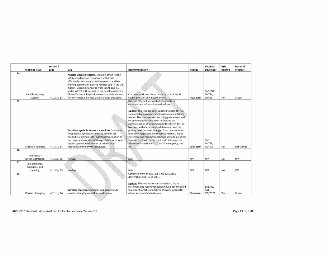
ANSI EVSP Standardization Roadmap for Electric Vehicles, Version 2.0 Page 138 of 170
Roadmap Issue Section / page Gap Recommendation Priority
Potential Developer
Grid Related
Status of Progress
14.
Audible Warning Systems 4.1.2.3 / 83
Audible warning systems. Creation of the NHTSA safety standard and compliance with it will effectively close any gap with respect to audible warning systems for electric vehicles sold in the U.S. market. Ongoing standards work in SAE and ISO, and in WP.29 with respect to the development of a Global Technical Regulation would provide a means for international harmonization around this issue.
Continue work on safety standards to address EV sound emission and measurement. Near‐term
SAE, ISO, NHTSA, WP.29 No Green
15.
Graphical Symbols 4.1.3.1 / 84
Graphical symbols for electric vehicles. Standards for graphical symbols for electric vehicles are needed to communicate important information to the driver such as state of charge, failure or normal system operation which can be understood regardless of the driver’s language.
Develop EV graphical symbols standards to communicate information to the driver. Update: The text has been updated to note NHTSA sponsored research on functional safety and failure modes. The roadmap version 1.0 gap statement and recommendation have been re‐focused on communication of information to the driver. NHTSA has been added as a potential developer and the priority level has been changed from near‐term to long‐term. Regarding the roadmap version 1.0 gap statement and recommendation relating to graphical symbols for “parts under the hood,” this aspect is addressed in section 4.3.1.1 on EV emergency shut off. Long‐term
SAE, NHTSA, ISO, IEC No Not started
16.
Telematics – Driver Distraction 4.1.3.2 / 85 No Gap N/A N/A N/A No N/A
17. Fuel Efficiency, Emissions, and
Labeling 4.1.3.3 / 85 No Gap N/A N/A N/A No N/A
18.
Wireless Charging 4.2.1.1 / 86 Wireless charging. Standards and guidelines for wireless charging are still in development.
Complete work on SAE J2954, UL 2750, IEEE deliverables and IEC 69180‐1. Update: The text and roadmap version 1.0 gap statement and recommendation have been modified to account for IEEE and IEC/TC 69 work, with both added as potential developers. Near‐term
SAE, UL, IEEE, IEC/TC 69 Yes Green
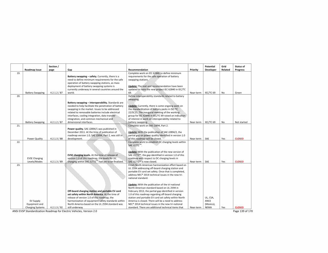
ANSI EVSP Standardization Roadmap for Electric Vehicles, Version 2.0 Page 139 of 170
Roadmap Issue Section / page Gap Recommendation Priority
Potential Developer
Grid Related
Status of Progress
19.
Battery Swapping 4.2.1.2 / 87
Battery swapping – safety. Currently, there is a need to define minimum requirements for the safe operation of battery swapping stations, as mass deployment of battery swapping systems is currently underway in several countries around the world.
Complete work on IEC 62840 to define minimum requirements for the safe operation of battery swapping stations. Update: The text and recommendation have been updated to note the new project IEC 62840 in IEC/TC 69. Near‐term IEC/TC 69 No Green
20.
Battery Swapping 4.2.1.2 / 87
Battery swapping – interoperability. Standards are needed to help facilitate the penetration of battery swapping in the market. Issues to be addressed related to removable batteries include electrical interfaces, cooling integration, data transfer integration, and common mechanical and dimensional interfaces.
Define interoperability standards related to battery swapping. Update: Currently, there is some ongoing work on the standardization of battery packs in ISO TC 22/SC21. The inaugural meeting of the working group for IEC 62840 in IEC/TC 69 raised an indication of interest in work on interoperability related to battery swapping. Near‐term IEC/TC 69 No Not started
21.
Power Quality 4.2.1.3 / 88
Power quality. SAE J2894/1 was published in December 2011. At the time of publication of roadmap version 1.0, SAE J2894, Part 2, was still in development.
Complete work on SAE J2894, Part 2. Update: With the publication of SAE J2894/2, the partial gap on power quality identified in version 1.0 of this roadmap will be closed. Near‐term SAE Yes CLOSED
22.
EVSE Charging Levels/Modes 4.2.1.3 / 89
EVSE charging levels. At the time of release of version 1.0 of this roadmap, the levels for DC charging within SAE J1772
TM had yet to be finalized.
Complete work to establish DC charging levels within SAE J1772
TM.
Update: With the publication of the new version of SAE J1772™, the gap identified in version 1.0 of this roadmap with respect to DC charging levels in SAE J1772™ is now closed. Near‐term SAE Yes CLOSED
23.
EV Supply Equipment and Charging Systems 4.2.1.3 / 92
Off‐board charging station and portable EV cord set safety within North America. At the time of release of version 1.0 of this roadmap, the harmonization of equipment safety standards within North America based on the UL 2594 standard was still underway
Finish North American harmonization effort based on UL 2594 addressing off‐board charging station and portable EV cord set safety. Once that is completed, address NEC® 2014 technical issues in the new tri‐national standard. Update: With the publication of the tri‐national North American standard based on UL 2594 in February 2013, the partial gap identified in version 1.0 of this roadmap regarding off‐board charging station and portable EV cord set safety within North America is closed. There will be a need to address NEC® 2014 technical issues in the new tri‐national standard. There are additional technical items that Near‐term
UL, CSA, ANCE (Mexico), NEMA Yes CLOSED
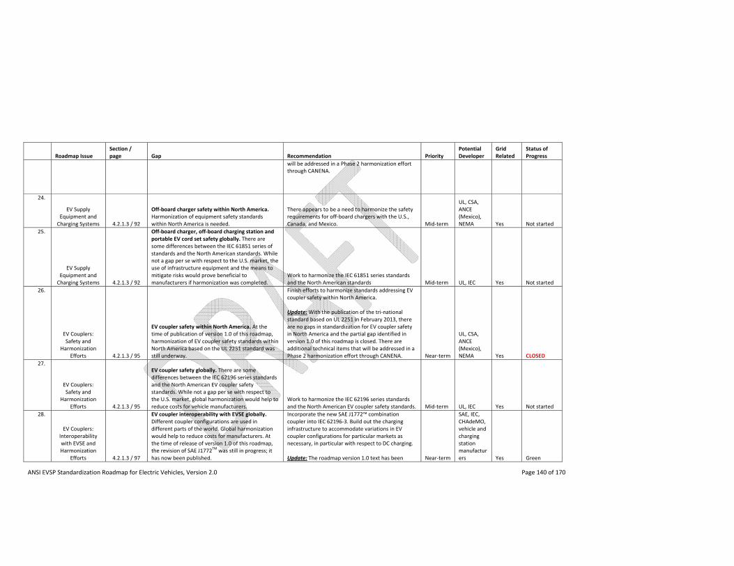
ANSI EVSP Standardization Roadmap for Electric Vehicles, Version 2.0 Page 140 of 170
Roadmap Issue Section / page Gap Recommendation Priority
Potential Developer
Grid Related
Status of Progress
will be addressed in a Phase 2 harmonization effort through CANENA.
24.
EV Supply Equipment and Charging Systems 4.2.1.3 / 92
Off‐board charger safety within North America. Harmonization of equipment safety standards within North America is needed.
There appears to be a need to harmonize the safety requirements for off‐board chargers with the U.S., Canada, and Mexico. Mid‐term
UL, CSA, ANCE (Mexico), NEMA Yes Not started
25.
EV Supply Equipment and Charging Systems 4.2.1.3 / 92
Off‐board charger, off‐board charging station and portable EV cord set safety globally. There are some differences between the IEC 61851 series of standards and the North American standards. While not a gap per se with respect to the U.S. market, the use of infrastructure equipment and the means to mitigate risks would prove beneficial to manufacturers if harmonization was completed.
Work to harmonize the IEC 61851 series standards and the North American standards Mid‐term UL, IEC Yes Not started
26.
EV Couplers: Safety and
Harmonization Efforts 4.2.1.3 / 95
EV coupler safety within North America. At the time of publication of version 1.0 of this roadmap, harmonization of EV coupler safety standards within North America based on the UL 2251 standard was still underway.
Finish efforts to harmonize standards addressing EV coupler safety within North America. Update: With the publication of the tri‐national standard based on UL 2251 in February 2013, there are no gaps in standardization for EV coupler safety in North America and the partial gap identified in version 1.0 of this roadmap is closed. There are additional technical items that will be addressed in a Phase 2 harmonization effort through CANENA. Near‐term
UL, CSA, ANCE (Mexico), NEMA Yes CLOSED
27.
EV Couplers: Safety and
Harmonization Efforts 4.2.1.3 / 95
EV coupler safety globally. There are some differences between the IEC 62196 series standards and the North American EV coupler safety standards. While not a gap per se with respect to the U.S. market, global harmonization would help to reduce costs for vehicle manufacturers.
Work to harmonize the IEC 62196 series standards and the North American EV coupler safety standards. Mid‐term UL, IEC Yes Not started
28.
EV Couplers: Interoperability with EVSE and Harmonization
Efforts 4.2.1.3 / 97
EV coupler interoperability with EVSE globally. Different coupler configurations are used in different parts of the world. Global harmonization would help to reduce costs for manufacturers. At the time of release of version 1.0 of this roadmap, the revision of SAE J1772
TM was still in progress; it
has now been published.
Incorporate the new SAE J1772™ combinationcoupler into IEC 62196‐3. Build out the charging infrastructure to accommodate variations in EV coupler configurations for particular markets as necessary, in particular with respect to DC charging. Update: The roadmap version 1.0 text has been Near‐term
SAE, IEC, CHAdeMO, vehicle and charging station manufacturers Yes Green
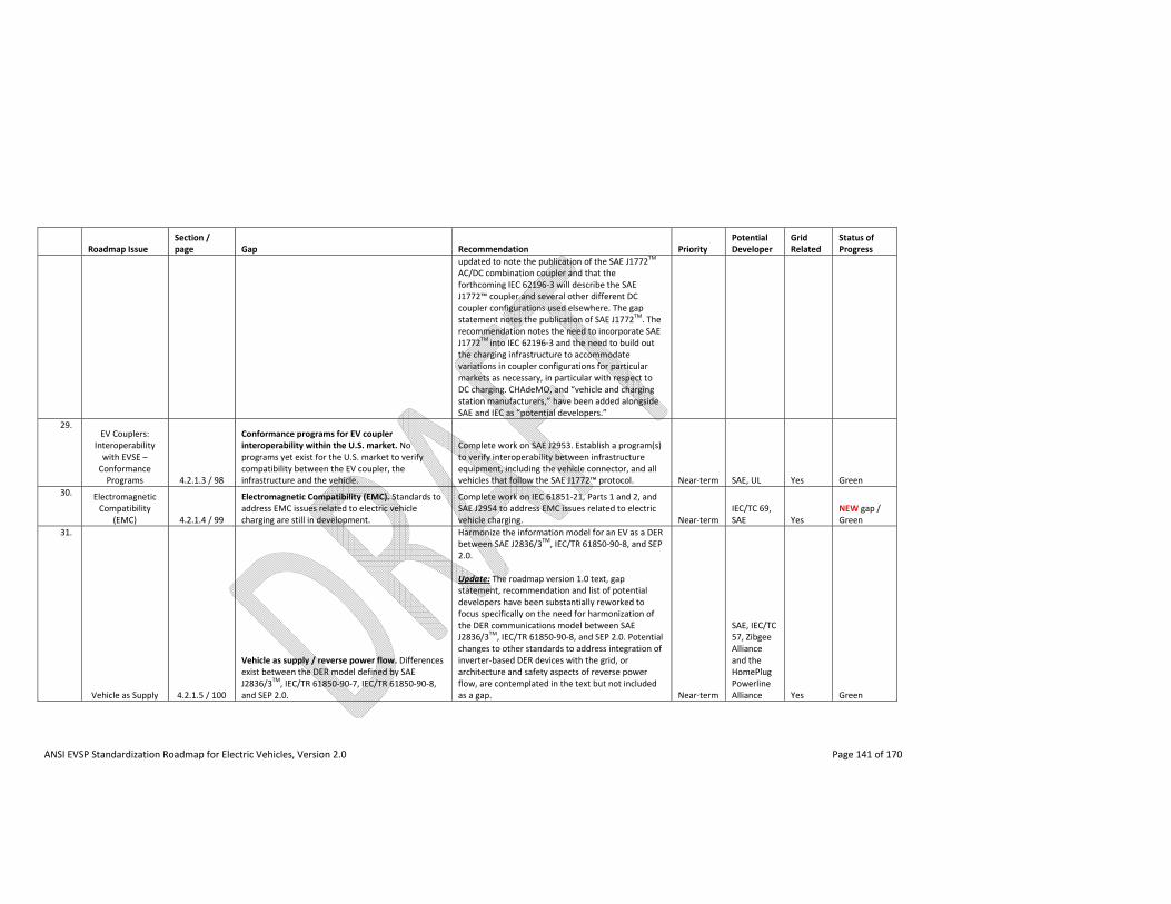
ANSI EVSP Standardization Roadmap for Electric Vehicles, Version 2.0 Page 141 of 170
Roadmap Issue Section / page Gap Recommendation Priority
Potential Developer
Grid Related
Status of Progress
updated to note the publication of the SAE J1772TM
AC/DC combination coupler and that the forthcoming IEC 62196‐3 will describe the SAE J1772™ coupler and several other different DC coupler configurations used elsewhere. The gap statement notes the publication of SAE J1772
TM. The
recommendation notes the need to incorporate SAE J1772
TM into IEC 62196‐3 and the need to build out
the charging infrastructure to accommodate variations in coupler configurations for particular markets as necessary, in particular with respect to DC charging. CHAdeMO, and “vehicle and charging station manufacturers,” have been added alongside SAE and IEC as “potential developers.”
29. EV Couplers:
Interoperability with EVSE – Conformance Programs 4.2.1.3 / 98
Conformance programs for EV coupler interoperability within the U.S. market. No programs yet exist for the U.S. market to verify compatibility between the EV coupler, the infrastructure and the vehicle.
Complete work on SAE J2953. Establish a program(s) to verify interoperability between infrastructure equipment, including the vehicle connector, and all vehicles that follow the SAE J1772™ protocol. Near‐term SAE, UL Yes Green
30. Electromagnetic Compatibility
(EMC) 4.2.1.4 / 99
Electromagnetic Compatibility (EMC). Standards to address EMC issues related to electric vehicle charging are still in development.
Complete work on IEC 61851‐21, Parts 1 and 2, and SAE J2954 to address EMC issues related to electric vehicle charging. Near‐term
IEC/TC 69, SAE Yes
NEW gap / Green
31.
Vehicle as Supply 4.2.1.5 / 100
Vehicle as supply / reverse power flow. Differences exist between the DER model defined by SAE J2836/3
TM, IEC/TR 61850‐90‐7, IEC/TR 61850‐90‐8,
and SEP 2.0.
Harmonize the information model for an EV as a DER between SAE J2836/3
TM, IEC/TR 61850‐90‐8, and SEP
2.0. Update: The roadmap version 1.0 text, gap statement, recommendation and list of potential developers have been substantially reworked to focus specifically on the need for harmonization of the DER communications model between SAE J2836/3
TM, IEC/TR 61850‐90‐8, and SEP 2.0. Potential
changes to other standards to address integration of inverter‐based DER devices with the grid, or architecture and safety aspects of reverse power flow, are contemplated in the text but not included as a gap. Near‐term
SAE, IEC/TC 57, Zibgee Alliance and the HomePlug Powerline Alliance Yes Green
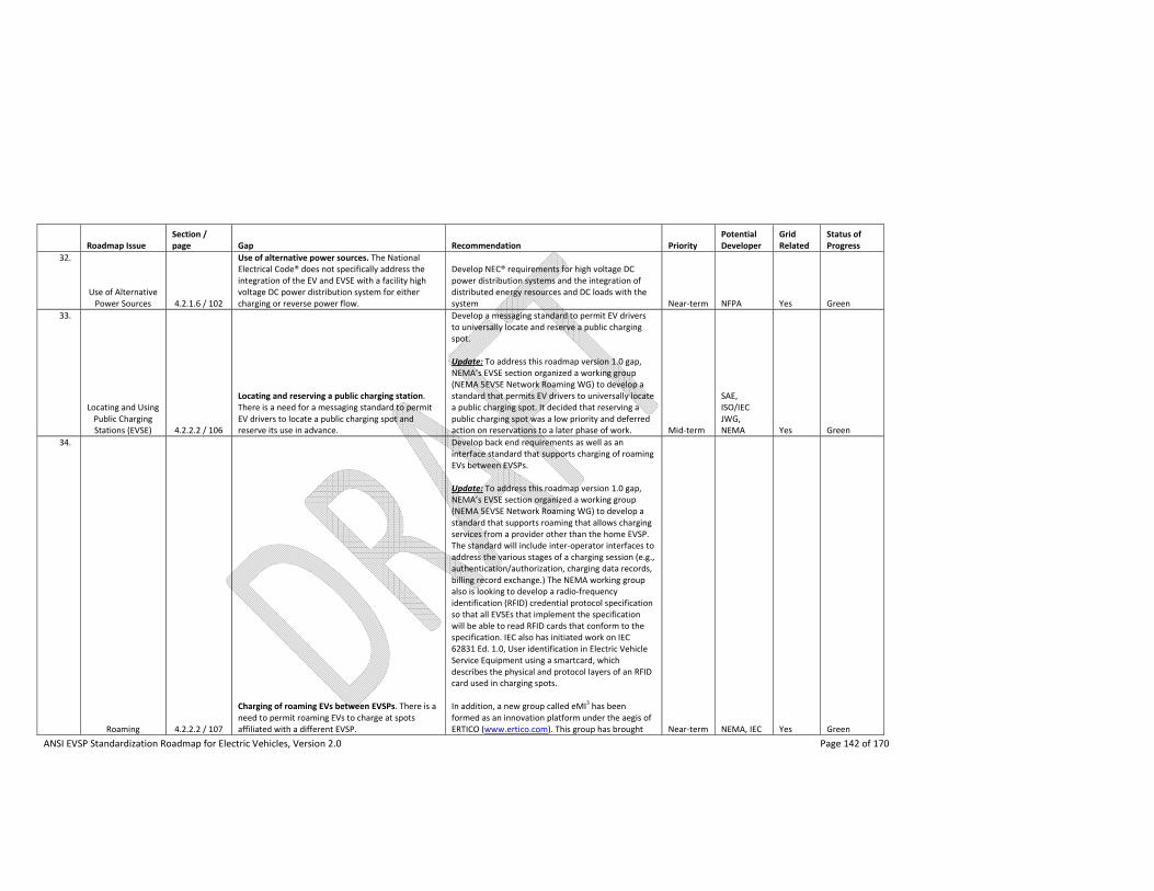
ANSI EVSP Standardization Roadmap for Electric Vehicles, Version 2.0 Page 142 of 170
Roadmap Issue Section / page Gap Recommendation Priority
Potential Developer
Grid Related
Status of Progress
32.
Use of Alternative Power Sources 4.2.1.6 / 102
Use of alternative power sources. The National Electrical Code® does not specifically address the integration of the EV and EVSE with a facility high voltage DC power distribution system for either charging or reverse power flow.
Develop NEC® requirements for high voltage DC power distribution systems and the integration of distributed energy resources and DC loads with the system Near‐term NFPA Yes Green
33.
Locating and Using Public Charging Stations (EVSE) 4.2.2.2 / 106
Locating and reserving a public charging station. There is a need for a messaging standard to permit EV drivers to locate a public charging spot and reserve its use in advance.
Develop a messaging standard to permit EV drivers to universally locate and reserve a public charging spot. Update: To address this roadmap version 1.0 gap, NEMA’s EVSE section organized a working group (NEMA 5EVSE Network Roaming WG) to develop a standard that permits EV drivers to universally locate a public charging spot. It decided that reserving a public charging spot was a low priority and deferred action on reservations to a later phase of work. Mid‐term
SAE, ISO/IEC JWG, NEMA Yes Green
34.
Roaming 4.2.2.2 / 107
Charging of roaming EVs between EVSPs. There is a need to permit roaming EVs to charge at spots affiliated with a different EVSP.
Develop back end requirements as well as an interface standard that supports charging of roaming EVs between EVSPs. Update: To address this roadmap version 1.0 gap, NEMA’s EVSE section organized a working group (NEMA 5EVSE Network Roaming WG) to develop a standard that supports roaming that allows charging services from a provider other than the home EVSP. The standard will include inter‐operator interfaces to address the various stages of a charging session (e.g., authentication/authorization, charging data records, billing record exchange.) The NEMA working group also is looking to develop a radio‐frequency identification (RFID) credential protocol specification so that all EVSEs that implement the specification will be able to read RFID cards that conform to the specification. IEC also has initiated work on IEC 62831 Ed. 1.0, User identification in Electric Vehicle Service Equipment using a smartcard, which describes the physical and protocol layers of an RFID card used in charging spots. In addition, a new group called eMI
3 has been
formed as an innovation platform under the aegis of ERTICO (www.ertico.com). This group has brought Near‐term NEMA, IEC Yes Green
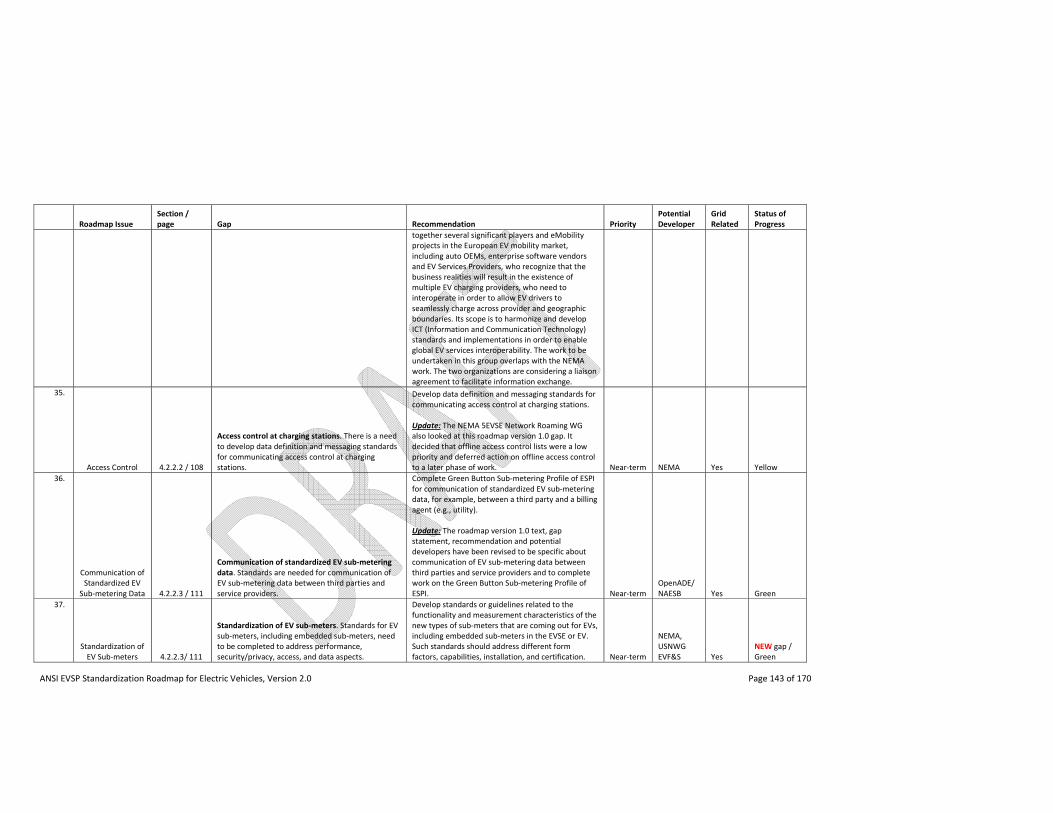
ANSI EVSP Standardization Roadmap for Electric Vehicles, Version 2.0 Page 143 of 170
Roadmap Issue Section / page Gap Recommendation Priority
Potential Developer
Grid Related
Status of Progress
together several significant players and eMobility projects in the European EV mobility market, including auto OEMs, enterprise software vendors and EV Services Providers, who recognize that the business realities will result in the existence of multiple EV charging providers, who need to interoperate in order to allow EV drivers to seamlessly charge across provider and geographic boundaries. Its scope is to harmonize and develop ICT (Information and Communication Technology) standards and implementations in order to enable global EV services interoperability. The work to be undertaken in this group overlaps with the NEMA work. The two organizations are considering a liaison agreement to facilitate information exchange.
35.
Access Control 4.2.2.2 / 108
Access control at charging stations. There is a need to develop data definition and messaging standards for communicating access control at charging stations.
Develop data definition and messaging standards for communicating access control at charging stations. Update: The NEMA 5EVSE Network Roaming WG also looked at this roadmap version 1.0 gap. It decided that offline access control lists were a low priority and deferred action on offline access control to a later phase of work. Near‐term NEMA Yes Yellow
36.
Communication of Standardized EV
Sub‐metering Data 4.2.2.3 / 111
Communication of standardized EV sub‐metering data. Standards are needed for communication of EV sub‐metering data between third parties and service providers.
Complete Green Button Sub‐metering Profile of ESPI for communication of standardized EV sub‐metering data, for example, between a third party and a billing agent (e.g., utility). Update: The roadmap version 1.0 text, gap statement, recommendation and potential developers have been revised to be specific about communication of EV sub‐metering data between third parties and service providers and to complete work on the Green Button Sub‐metering Profile of ESPI. Near‐term
OpenADE/NAESB Yes Green
37.
Standardization of EV Sub‐meters 4.2.2.3/ 111
Standardization of EV sub‐meters. Standards for EV sub‐meters, including embedded sub‐meters, need to be completed to address performance, security/privacy, access, and data aspects.
Develop standards or guidelines related to the functionality and measurement characteristics of the new types of sub‐meters that are coming out for EVs, including embedded sub‐meters in the EVSE or EV. Such standards should address different form factors, capabilities, installation, and certification. Near‐term
NEMA, USNWG EVF&S Yes
NEW gap / Green
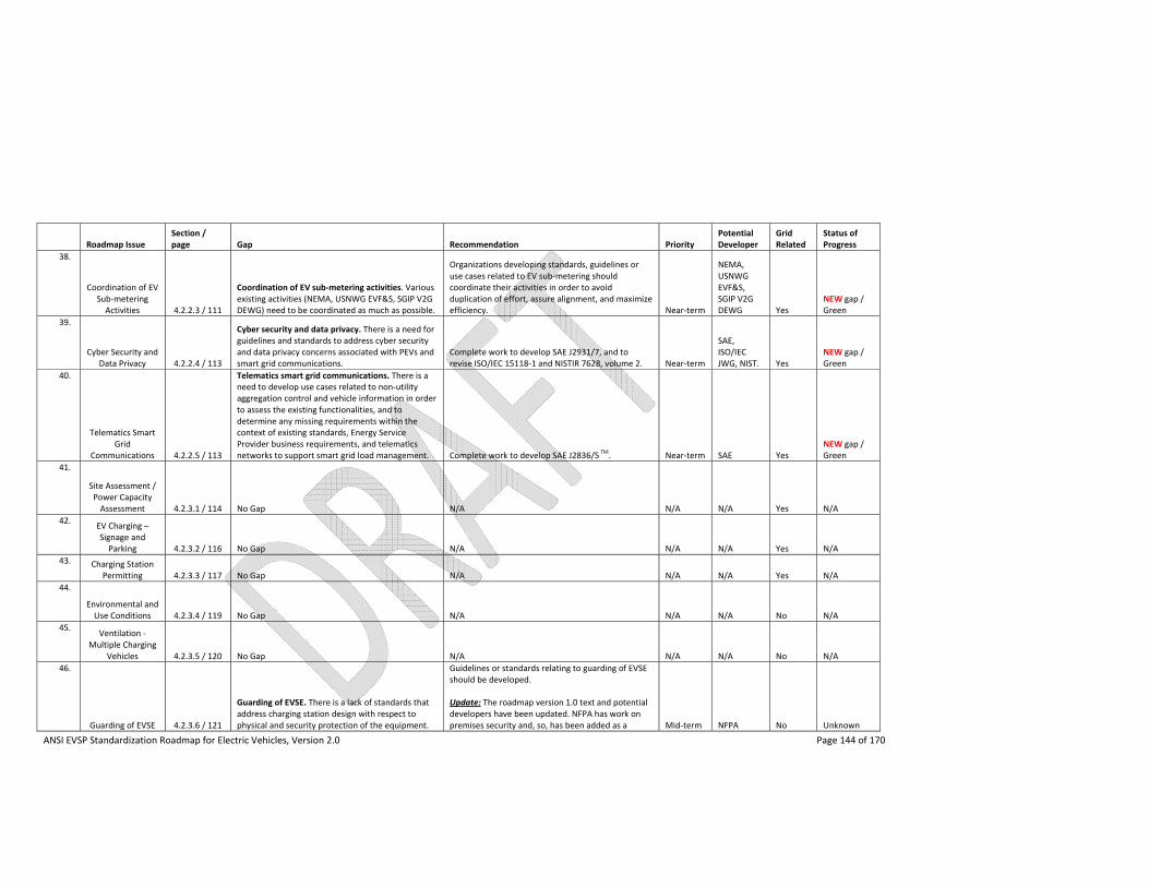
ANSI EVSP Standardization Roadmap for Electric Vehicles, Version 2.0 Page 144 of 170
Roadmap Issue Section / page Gap Recommendation Priority
Potential Developer
Grid Related
Status of Progress
38.
Coordination of EV Sub‐metering Activities 4.2.2.3 / 111
Coordination of EV sub‐metering activities. Various existing activities (NEMA, USNWG EVF&S, SGIP V2G DEWG) need to be coordinated as much as possible.
Organizations developing standards, guidelines or use cases related to EV sub‐metering should coordinate their activities in order to avoid duplication of effort, assure alignment, and maximize efficiency. Near‐term
NEMA, USNWG EVF&S, SGIP V2G DEWG Yes
NEW gap / Green
39.
Cyber Security and Data Privacy 4.2.2.4 / 113
Cyber security and data privacy. There is a need for guidelines and standards to address cyber security and data privacy concerns associated with PEVs and smart grid communications.
Complete work to develop SAE J2931/7, and to revise ISO/IEC 15118‐1 and NISTIR 7628, volume 2. Near‐term
SAE, ISO/IEC JWG, NIST. Yes
NEW gap / Green
40.
Telematics Smart Grid
Communications 4.2.2.5 / 113
Telematics smart grid communications. There is a need to develop use cases related to non‐utility aggregation control and vehicle information in order to assess the existing functionalities, and to determine any missing requirements within the context of existing standards, Energy Service Provider business requirements, and telematics networks to support smart grid load management. Complete work to develop SAE J2836/5
TM. Near‐term SAE Yes
NEW gap / Green
41.
Site Assessment / Power Capacity Assessment 4.2.3.1 / 114 No Gap N/A N/A N/A Yes N/A
42. EV Charging – Signage and Parking 4.2.3.2 / 116 No Gap N/A N/A N/A Yes N/A
43. Charging Station Permitting 4.2.3.3 / 117 No Gap N/A N/A N/A Yes N/A
44.
Environmental and Use Conditions 4.2.3.4 / 119 No Gap N/A N/A N/A No N/A
45. Ventilation ‐
Multiple Charging Vehicles 4.2.3.5 / 120 No Gap N/A N/A N/A No N/A
46.
Guarding of EVSE 4.2.3.6 / 121
Guarding of EVSE. There is a lack of standards that address charging station design with respect to physical and security protection of the equipment.
Guidelines or standards relating to guarding of EVSE should be developed. Update: The roadmap version 1.0 text and potential developers have been updated. NFPA has work on premises security and, so, has been added as a Mid‐term NFPA No Unknown
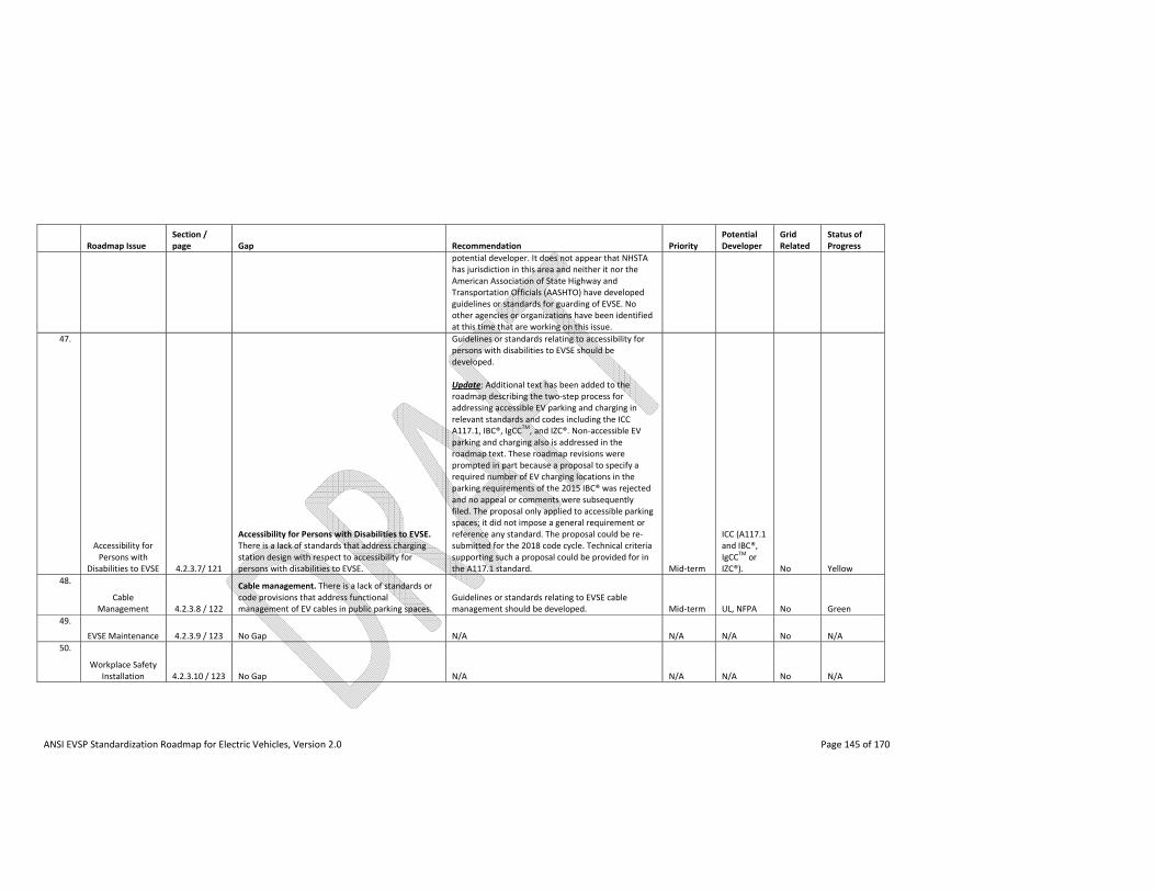
ANSI EVSP Standardization Roadmap for Electric Vehicles, Version 2.0 Page 145 of 170
Roadmap Issue Section / page Gap Recommendation Priority
Potential Developer
Grid Related
Status of Progress
potential developer. It does not appear that NHSTA has jurisdiction in this area and neither it nor the American Association of State Highway and Transportation Officials (AASHTO) have developed guidelines or standards for guarding of EVSE. No other agencies or organizations have been identified at this time that are working on this issue.
47.
Accessibility for Persons with
Disabilities to EVSE 4.2.3.7/ 121
Accessibility for Persons with Disabilities to EVSE. There is a lack of standards that address charging station design with respect to accessibility for persons with disabilities to EVSE.
Guidelines or standards relating to accessibility for persons with disabilities to EVSE should be developed. Update: Additional text has been added to the roadmap describing the two‐step process for addressing accessible EV parking and charging in relevant standards and codes including the ICC A117.1, IBC®, IgCC
TM, and IZC®. Non‐accessible EV
parking and charging also is addressed in the roadmap text. These roadmap revisions were prompted in part because a proposal to specify a required number of EV charging locations in the parking requirements of the 2015 IBC® was rejected and no appeal or comments were subsequently filed. The proposal only applied to accessible parking spaces; it did not impose a general requirement or reference any standard. The proposal could be re‐submitted for the 2018 code cycle. Technical criteria supporting such a proposal could be provided for in the A117.1 standard. Mid‐term
ICC (A117.1 and IBC®, IgCC
TM or
IZC®). No Yellow
48.
Cable Management 4.2.3.8 / 122
Cable management. There is a lack of standards or code provisions that address functional management of EV cables in public parking spaces.
Guidelines or standards relating to EVSE cable management should be developed. Mid‐term UL, NFPA No Green
49.
EVSE Maintenance 4.2.3.9 / 123 No Gap N/A N/A N/A No N/A
50.
Workplace Safety Installation 4.2.3.10 / 123 No Gap N/A N/A N/A No N/A
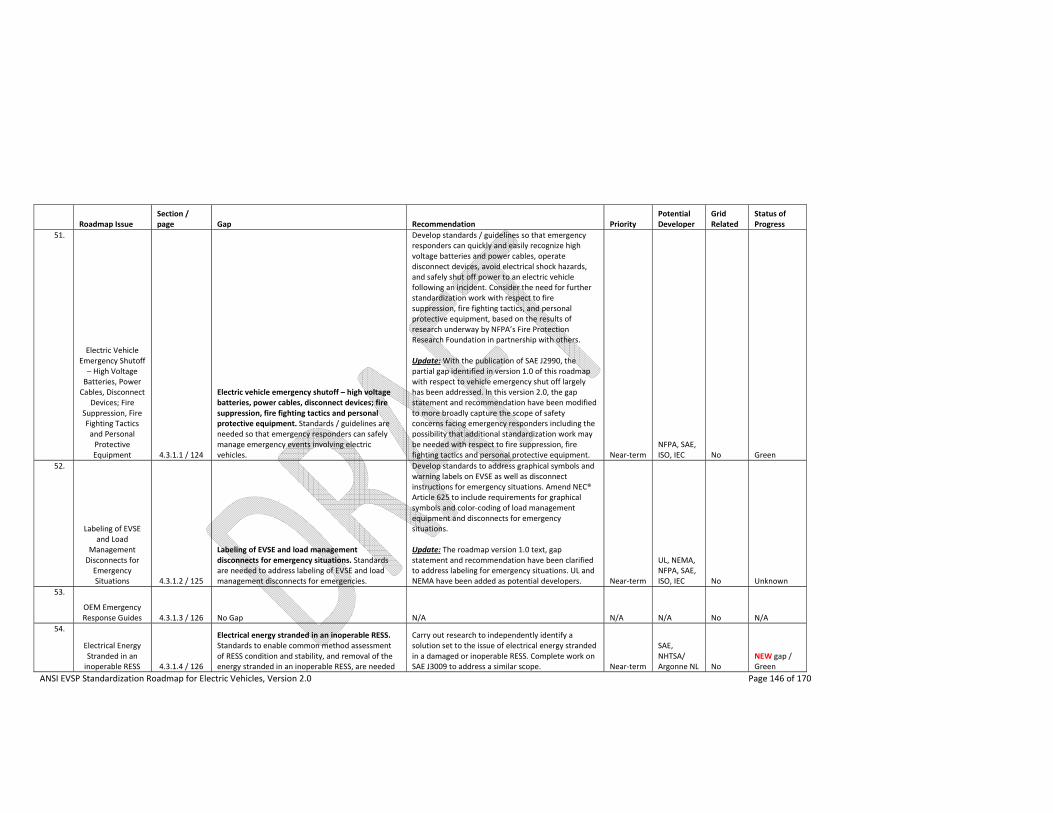
ANSI EVSP Standardization Roadmap for Electric Vehicles, Version 2.0 Page 146 of 170
Roadmap Issue Section / page Gap Recommendation Priority
Potential Developer
Grid Related
Status of Progress
51.
Electric Vehicle Emergency Shutoff – High Voltage Batteries, Power Cables, Disconnect
Devices; Fire Suppression, Fire Fighting Tactics and Personal Protective Equipment 4.3.1.1 / 124
Electric vehicle emergency shutoff – high voltage batteries, power cables, disconnect devices; fire suppression, fire fighting tactics and personal protective equipment. Standards / guidelines are needed so that emergency responders can safely manage emergency events involving electric vehicles.
Develop standards / guidelines so that emergency responders can quickly and easily recognize high voltage batteries and power cables, operate disconnect devices, avoid electrical shock hazards, and safely shut off power to an electric vehicle following an incident. Consider the need for further standardization work with respect to fire suppression, fire fighting tactics, and personal protective equipment, based on the results of research underway by NFPA’s Fire Protection Research Foundation in partnership with others. Update: With the publication of SAE J2990, the partial gap identified in version 1.0 of this roadmap with respect to vehicle emergency shut off largely has been addressed. In this version 2.0, the gap statement and recommendation have been modified to more broadly capture the scope of safety concerns facing emergency responders including the possibility that additional standardization work may be needed with respect to fire suppression, fire fighting tactics and personal protective equipment. Near‐term
NFPA, SAE, ISO, IEC No Green
52.
Labeling of EVSE and Load
Management Disconnects for Emergency Situations 4.3.1.2 / 125
Labeling of EVSE and load management disconnects for emergency situations. Standards are needed to address labeling of EVSE and load management disconnects for emergencies.
Develop standards to address graphical symbols and warning labels on EVSE as well as disconnect instructions for emergency situations. Amend NEC® Article 625 to include requirements for graphical symbols and color‐coding of load management equipment and disconnects for emergency situations. Update: The roadmap version 1.0 text, gap statement and recommendation have been clarified to address labeling for emergency situations. UL and NEMA have been added as potential developers. Near‐term
UL, NEMA, NFPA, SAE, ISO, IEC No Unknown
53.
OEM Emergency Response Guides 4.3.1.3 / 126 No Gap N/A N/A N/A No N/A
54.
Electrical Energy Stranded in an inoperable RESS 4.3.1.4 / 126
Electrical energy stranded in an inoperable RESS. Standards to enable common method assessment of RESS condition and stability, and removal of the energy stranded in an inoperable RESS, are needed
Carry out research to independently identify a solution set to the issue of electrical energy stranded in a damaged or inoperable RESS. Complete work on SAE J3009 to address a similar scope. Near‐term
SAE, NHTSA/ Argonne NL No
NEW gap / Green
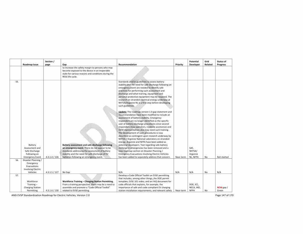
ANSI EVSP Standardization Roadmap for Electric Vehicles, Version 2.0 Page 147 of 170
Roadmap Issue Section / page Gap Recommendation Priority
Potential Developer
Grid Related
Status of Progress
to increase the safety margin to persons who may become exposed to the device in an inoperable state for various reasons and conditions during the RESS life cycle.
55.
Battery Assessment and Safe Discharge Following an
Emergency Event 4.3.1.4 / 126
Battery assessment and safe discharge following an emergency event. There do not appear to be standards addressing the assessment of battery stability and the need for safe discharge of EV batteries following an emergency event.
Standards and/or guidelines to assess battery stability and the need for safe discharge following an emergency event are needed to identify safe practices for performing such assessment and discharge and what training, equipment and personal protective equipment may be required. The research on stranded electrical energy underway at NHTSA/Argonne NL is a first step before developing such guidelines. Update: The roadmap version 1.0 gap statement and recommendation have been modified to include an assessment of battery stability. Emergency responders are no longer identified as the specific user of battery discharge procedures since second responders (tow operators, roadside assistance) and OEM representatives also may need such training. The development of such procedures is now described as contingent upon research underway by NHTSA / Argonne National Laboratory on stranded energy. Argonne and NFPA have been added as potential developers. Text regarding safe battery recharge in emergencies has been removed and a new roadmap section on Disaster Planning / Emergency Evacuations Involving Electric Vehicles has been added to separately address that concern. Near‐term
SAE, NHTSA/ Argonne NL, NFPA No Not started
56. Disaster Planning / Emergency Evacuations
Involving Electric Vehicles 4.3.1.5 / 127 No Gap N/A N/A N/A No N/A
57.
Workforce Training –
Charging Station Permitting 4.3.1.6 / 130
Workforce Training – Charging Station Permitting. From a training perspective, there may be a need to assemble and promote a “Code Official Toolkit” related to EVSE permitting.
Develop a Code Official Toolkit on EVSE permitting that includes, among other things, the DOE permit template, EVSE 101 video, and an FAQ document for code officials that explains, for example, the importance of safe and code‐compliant EV charging station installation requirements, and relevant safety Near‐term
DOE, ICC, NECA, IAEI, NFPA No
NEW gap / Green
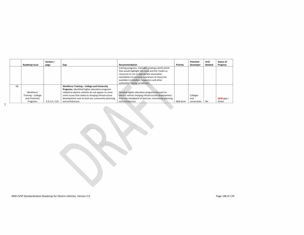
ANSI EVSP Standardization Roadmap for Electric Vehicles, Version 2.0 Page 148 of 170
Roadmap Issue Section / page Gap Recommendation Priority
Potential Developer
Grid Related
Status of Progress
training programs. Consider creating a brief article that would highlight this issue and the Toolkit as resources to run in appropriate association newsletters to increase awareness of resources available to installers, inspectors and other authorities having jurisdiction.
58.
Workforce Training – College and University Programs 4.3.1.6 / 131
Workforce Training – College and University Programs. Identified higher education programs related to electric vehicles do not appear to cover some issues that relate to charging infrastructure development such as land use, community planning, and architecture.
Develop higher education programs focused on electric vehicle charging infrastructure development from the standpoint of land use, community planning and architecture. Mid‐term
Colleges and universities No
NEW gap / Green
1
ANSI EVSP Standardization Roadmap for Electric Vehicles, Version 2.0 Page 149 of 170
6. On the Horizon 1
While this roadmap represents a specific snapshot in time, it maintains a distinctively outward looking, 2
over the horizon posture that will continue to facilitate discussions with domestic, regional and 3
international partners regarding coordination and harmonization of standardization activities and 4
adaptation to technological and policy changes. 5
The DOE EV Everywhere Grand Challenge Blueprint12 outlines technology challenges that must be 6
overcome if the EV market is to become ubiquitous. Battery technology is focused on improving 7
performance and reducing costs. In the short‐term, the goal is to double lithium‐ion battery pack energy 8
density, whereas the longer‐term goal is to explore other battery chemistries that may offer significantly 9
greater energy densities than li‐ion. Reducing the costs of electric drive systems is also a goal, through 10
the development of advanced power electronics, electric motors and traction drive system technologies. 11
The goals of reducing the weight of electric vehicles using lightweight metals and composites, and 12
introducing more energy efficient climate control technologies, will help to extend vehicle range. Aside 13
from enhancements to the vehicles, there are supporting efforts aimed at expanding the charging 14
infrastructure such as the EV Everywhere Workplace Charging Challenge. 15
Developing technologies may also introduce new opportunities into the rapidly evolving landscape for 16
EVs and charging infrastructure. For example, wireless charging potentially may offer a level of 17
convenience that does not exist today. And as PEVs become more fully integrated into the smart grid, 18
there is likely to be increased interest in exploiting their use as distributed energy resources. 19
Depending upon the needs of stakeholders, and available resources, periodic updates on significant 20
electric vehicle standardization activities and progress to address the gaps identified in this roadmap will 21
be made. Issues that are new or that require further discussion also may be explored The aim behind 22
any such efforts will be to continue to help guide, coordinate, and enhance the standards landscape as 23
needed to support the widespread introduction of PEVs and charging infrastructure. 24
25
12 http://www1.eere.energy.gov/vehiclesandfuels/electric_vehicles/pdfs/eveverywhere_blueprint.pdf

ANSI EVSP Standardization Roadmap for Electric Vehicles, Version 2.0 Page 150 of 170
1
2
3
4
5
6
7
[this page intentionally left blank] 8
Appendix A. EV Charging Actors and Communications
ANSI EVSP Standardization Roadmap for Electric Vehicles, Version 2.0 Page 151 of 170
Appendix A. EV Charging Actors and Communications 1
A.1 Introduction 2
This appendix provides an overview of the current and envisioned EV charging infrastructure, and at a 3
high level describes the components of this infrastructure that may require or benefit from 4
communications between those components. It lists the main actors involved in the communications 5
and provides a sampling of various types of communications between them. The term actor refers to 6
any system that communicates with another system for the purpose of enabling or enhancing some 7
aspect of EV charging. 8
This appendix does not provide details about the overall electric grid, nor about the smart grid 9
communications within the electric grid's generation, transmission and distribution systems. Rather, it 10
focuses on those aspects of the electrical infrastructure and communications that are specific to 11
charging EVs.12
13
A.2 Role of Communications in EV Charging Infrastructure 14
The basic communications requirement for EV charging is to facilitate the transfer of power from the 15
EVSE to the EV. The conductive charging interface standard in North America for all AC Level 1 and 2 16
EVSE, and DC combo charger products, is SAE J1772TM. This standard provides the specifications for the 17
AC‐only and AC/DC combo connectors and vehicle inlets, and also provides the basic sequence of 18
control pilot signals and charge control communications between the EV and the EVSE or DC charger, to 19
ensure a safe interconnection and power transfer process. 20
Beyond the SAE J1772TM required charging communications, there are information and control 21
communications technology functions that add new dimensions to the EV charging process. The added 22
dimensions that communications offers to EV charging are the capability for utilities to monitor and 23
interactively manage EV charging loads – to maintain the reliability and improve the efficiency of their 24
respective distribution grids. Communications will also provide consumer interaction for automated 25
access to utility special EV time of use (TOU) rate tariffs, incentivized demand response programs, 26
charging status, and EV charging electricity consumption information. EV customers will be able to set 27
specific schedule parameters and preferences for EV charging, enabling the ability to cost‐effectively 28
manage their charging behavior and minimize impact to the grid. This requires bi‐directional 29
communications functionality between the utility and the EV customers. 30
Consider the scenario of charging an EV in a single family home (e.g., in the garage). The utility 31
communicates its EV TOU rate tariff and schedule information to the EV or to an EVSE. The customer 32
accesses the information either directly using interactive displays in the EV and/or EVSE or through a 33
smart phone, website, etc. The EV and/or EVSE can then be programmed by the customer to only allow 34
Appendix A. EV Charging Actors and Communications
ANSI EVSP Standardization Roadmap for Electric Vehicles, Version 2.0 Page 152 of 170
charging during the times electricity rates are cheapest, typically at night and in the early morning 1
during the utility off‐peak period. 2
Another scenario involves a cluster of EVs in a residential area that if charged simultaneously may stress 3
the capacity of the utility transformer. The utility, via communications connectivity to the EV, EVSE, or 4
an entity that manages the EVSEs, may be able to query the EV load on a particular transformer, and if 5
necessary, send out a demand response signal to the EVs and/or EVSEs to either stop charging or to 6
curtail the charge power level for a specified period of time. The customer would have the ability to opt‐7
out of the demand response event based on their specific circumstances. 8
An example of communications enhancing the electricity infrastructure is the Green Button initiative. 9
This provides a way for consumers to download their electricity usage from their utilities or designated 10
third parties. Coupled with smart metering infrastructure, consumers can view almost real‐time data 11
about their usage patterns. 12
Communications is a powerful enhancement to the basic charging scenario. In some cases it is actively 13
required; in others it provides value beyond the actual charging itself and enables new applications to 14
be created and delivered. 15
Communications is not limited to the communication between the utility, the EV and the EVSE. As the 16
next section describes, the path from the producer (i.e., the utility) to the consumer of energy (i.e., the 17
EV) may involve other intermediary systems that communicate with each other. 18
A.3 EV Charging Aspect of the Smart Grid 19
In order to understand the communications requirements of EV charging infrastructure, one must 20
examine the different actors, applications and business models involved in EV charging. 21
EV charging is, at a very high level, similar to other markets where goods are created by a producer, 22
delivered to a consumer via an intermediary, and offered for consumption via multiple outlets. 23
Consider applications such as TV or video content, which involve creation, transmission and distribution 24
of content (e.g., TV programs) to end users over different communications media such as wireline (e.g., 25
cable, DSL, fiber) or wireless (e.g., satellite, 3G/4G services, over‐the‐air HDTV). In each of the above 26
media, different communication protocols may be used to accomplish tasks specific to the medium and 27
to the business model that best supports that medium. Also, depending on whether the content is 28
delivered to a private or a public destination, a user may need to be authenticated to access 29
subscription content. For example, a consumer receiving over‐the‐air HDTV programming typically does 30
not require authentication in order to view the content, whereas a consumer enjoying the same 31
program on a device via the Internet must be authenticated by a service provider (e.g., Comcast, AT&T) 32
and/or by the content provider (e.g., Netflix, HBO, Major League Baseball). A consumer may also have 33
multiple ways to obtain information about available programming content. As an example, a user may 34
view an electronic programming guide (EPG) on a set‐top box connected to a television; may look up 35
programming information on a service provider's website; may access EPG‐style information on a 36
Appendix A. EV Charging Actors and Communications
ANSI EVSP Standardization Roadmap for Electric Vehicles, Version 2.0 Page 153 of 170
website or via a mobile device application (e.g., TVGuide.com or a TVGuide app); or may obtain 1
programming information via a specific channel’s website (e.g., networks, local origination stations). 2
This appendix is primarily concerned with the consumer end of the network. From the consumer's 3
perspective, details of the overall service delivery network are of little concern. Rather, the consumption 4
end of the network, often called the "last mile," is of vital importance. For example, the TV consumer is 5
interested in the quality of the viewing experience, including high‐quality video (which implies no 6
pixelation or macroblocking), perfect or near‐perfect (sub‐100 ms) audio‐video synchronization, and 7
sufficiently low‐latency remote control response. Other concerns include options for content delivery to 8
multiple TVs in the home, cost of receiving the service, and capability to view service provider content 9
on mobile devices, among many others. Similarly, with regard to EV charging, this appendix is mainly 10
concerned with communication aspects of how the EV is charged and the user billed, rather than 11
communication within utility (i.e., Energy Service Provider) networks. 12
Note that the business relationships are also different, based on the usage scenario. In order to view the 13
same content in different scenarios, the consumer may need to establish transient or longer‐term 14
associations with the content provider, the distributor, the service provider, and others. Competition 15
between various providers is almost always in the consumer's best interest. The different players or 16
actors in the market may compete or cooperate to provide unique and/or cost‐effective services. 17
Depending on variables such as the location of the charger, the business entity that owns and operates 18
the charger, and the type of charging offered, different business models may be used in order to obtain 19
a return on investment in the charging infrastructure. Also, the EV driver may be billed for multiple 20
aspects of EV charging, such as monthly access fees, per‐kWh tariffs, fees related to the time the EV 21
occupied the EVSE/parking spot, fees related to additional services such as the ability to reserve 22
stations, etc. Some examples of different business models are: 23
- For charging in a single family home, the business model may be the same as the existing model 24
for the home's electricity consumption. Here the business relationship may be directly between 25
the utility and the home owner. 26
- In a multi‐dwelling unit (MDU) such as an apartment complex, the MDU owner may install 27
several shared charging stations for use by their tenants. In this case, there may be an additional 28
business relationship between the tenants and the MDU owner. For example, tenants may pay a 29
monthly access fee and also pay per kWh fees. Also, access to the charging stations may be 30
restricted to only those tenants that establish this business relationship. The management of the 31
charging stations may be outsourced to an EV Services Provider. 32
- A retailer may offer free or subsidized charging at their premise, in order to attract a certain 33
demographic of customers and to encourage them to stay longer at the store. At such locations, 34
the retailer may offer additional incentives based on loyalty cards. An EV Services Provider may 35
manage the charging stations at such locations. 36
- The hospitality (hotel) industry may offer free or subsidized charging for similar reasons. 37
- For public charging on city streets, the city may install and operate charging stations, optionally 38
managed by an EV Services Provider. Since such charging stations may be used by a large 39
Appendix A. EV Charging Actors and Communications
ANSI EVSP Standardization Roadmap for Electric Vehicles, Version 2.0 Page 154 of 170
number of drivers, the EV Services Provider may offer drivers the ability to search for EVSEs and 1
reserve them. The EV Services Provider may derive revenue from the city as well as from the 2
driver for these services. 3
- An EV manufacturer (OEM) or an affiliated Telematics Provider may offer services substantially 4
similar to an EV Services Provider ‐ in fact, they can be considered a type of EV Services Provider. 5
The EV Manufacturer may provide subsidized charging to its customers at EVSEs it operates. 6
- At commercial & industrial locations, EVSEs may be operated by a corporation for restricted use 7
by its employees and visitors. Alternatively, use of the EVSEs may be restricted during certain 8
times of the day only, or could be subsidized for employees but not for non‐employee drivers. 9
10
The infrastructure communications required to support these different use cases and business models 11
are varied and use different communication protocols to accomplish their purposes. For example, an EV 12
may communicate with the utility via its telematics network, to download tariffs and make decisions 13
about when to charge, based on cost. An EV may alternatively communicate with an EVSE to get the 14
same information. Different EV Services Providers may compete for the EV driver's business. 15
Even though some business models today offer free EV charging, that is not likely to be the case in the 16
future and eventually the consumer will need to pay for the electricity their EV is consuming. This means 17
that the consumer must be recognized (i.e., authenticated), authorized (i.e., allowed access to the 18
type/amount of charging for which they've paid) and their charging sessions must be accounted (i.e., 19
metered), so that they can be billed appropriately. 20
Furthermore, the unique properties of EV charging bring with them additional requirements for 21
communication. 22
Since an EV can take several hours to charge, the driver will typically be away while the EV is charging. 23
Therefore, it is important that the driver be notified if there is a charging fault, or when charging is 24
completed. In addition, being able to find charging stations and check whether they are available, check 25
their pricing, and possibly reserve their use, is considered to be a useful value‐add. 26
From the perspective of the utility, since EVs can consume a significant amount of energy, there needs 27
to be a way to control or manage their load on the grid at times of peak demand. Communications allow 28
the utility and EVs to be able to perform such functions in real time and in a flexible way. Intermediary 29
actors may assist these communications. For example, a demand response aggregator or an Energy 30
Management System may aggregate the load of a large number of EVs, and communicate with the 31
utility on behalf of the group of EVs. An End Use Measurement Device (EUMD) may be provided to offer 32
special tariffs and help customers shift loads for demand management. 33
EVs can also act as a distributed energy resource. They can then act as a source of energy and feed 34
energy back into the home or into the grid when required. In order to do so, it may be necessary or 35
desirable for communications to happen. 36
Appendix A. EV Charging Actors and Communications
ANSI EVSP Standardization Roadmap for Electric Vehicles, Version 2.0 Page 155 of 170
A.4 Functional View of EV Charging Infrastructure Communications 1
This section lists some of the functions that may be enabled or enhanced by EV charging infrastructure 2
communications. 3
AAA (Authentication, Authorization and Accounting) 4
AAA (Authentication, Authorization and Accounting) functions are commonly deployed in multiple 5
markets (such as cellular voice/data) and require communication between the consumer device 6
(EV/EVSE) and the provider's AAA back end systems. Depending on the business model, an EV driver 7
may need to be identified and authenticated, in order to access charging services that the driver has 8
authorization to use. While charging is in progress, charging records must be sent to appropriate actors, 9
so that the energy consumed by the EV is correctly recorded and used for billing and potential future 10
taxation purposes. 11
Access Control 12
EVSE owners may wish to restrict charging services. A company may want to provide EV charging only to 13
its employees, or it may wish to restrict charging services to its employees during working hours and 14
allow anybody to charge outside of working hours. This requires access control mechanisms to be 15
downloaded to the EVSEs, or a network where the EVSEs can query whether a driver can access the 16
EVSEs. 17
Charging 18
The process of charging itself may require communications between the EVSE, the EV and other actors, 19
to coordinate the direction, time, and amount of electricity. Basic communication between the EVSE and 20
the EV, as defined in SAE J1772™ or IEC 61851‐1, may be used to coordinate the amount of electricity 21
and provide other charging related functionality. However, a higher‐level communication is required to 22
facilitate advanced functionalities, such as DC charging or bi‐directional energy flow. 23
Depending on the scenario, infrastructure capabilities, and agreements in place, communications used 24
for charging control may also address prices, customer preferences, local demand, or other criteria, and 25
may be managed by the EV, EVSE, a local Energy Management System, third party, service provider, 26
over the internet, or using mobile devices, among others. Additionally, driver notification messages may 27
be necessary when faults occur, when the EV battery is full, or when other conditions occur. 28
Demand Response, Demand Shifting, Energy Storage and Distributed Energy Resource 29
From the standpoint of grid stability and customer costs, demand response, demand shifting, energy 30
storage, and EV as distributed energy resource are applications that are considered to be important 31
functions of the smart grid. Demand response can be considered a function of the service provider 32
whereby, with permission of the EV operator, charging is temporarily stopped or limited due to local or 33
distribution grid constraints. Demand shifting is more likely to be done by the EV operator based on 34
Appendix A. EV Charging Actors and Communications
ANSI EVSP Standardization Roadmap for Electric Vehicles, Version 2.0 Page 156 of 170
pricing messages, EV tariffs (combined with EV measurement), facility demand, or a combination of 1
these factors. Energy storage in relation to an EV consists of the use of on‐board or off‐board batteries 2
that may be used to provide energy to or from the EV when electricity costs are high (e.g., during peak 3
time periods) or, combined with reverse energy flow, during emergencies as a back‐up power source. As 4
a device that may be able to supply power or other ancillary services back to the grid, an EV can also be 5
considered a distributed energy resource (DER). 6
EVs that participate in these functions may require communications between a service provider or 7
intermediate entity such as an aggregator or an EV operator and the EVs/EVSEs. 8
Measurement (metering), Pricing (tariffs) and Billing 9
The discrete measurement of EV energy consumption can be considered a necessary function of EV 10
charging for many reasons. In home charging scenarios, EV metering and tariffs provide utilities the 11
ability to incentivize customers to shift charging to off peak times with less grid demand. To do this, 12
utilities may provide special tariffs for the energy consumed by their EVs, that can be deducted from the 13
bill if the meter is downstream of the premises meter (e.g., sub‐metering) or billed separately if the EV 14
usage is not recorded by the premises meter (e.g., separate metering). These meters (often called End 15
Use Measurement Devices or EUMDs), which may be located near the premises meter, on an outlet, or 16
in the EVSE or EV, must be able to communicate consumption and timing data back to the utility or third 17
party (in certain circumstances) to apply the charges. In addition to the benefits of grid protection and 18
reduced customer costs, these special tariffs and rates may also help drive the adoption of EVs. 19
In commercial charging scenarios, similar to home charging scenarios, utilities may provide special rates 20
for the time and amount of charging. Facilities may also use the discrete measurement of EV charging to 21
monitor and manage their own loads in order to minimize demand charges. 22
Many public charging scenarios involving EUMDs are possible. The charging provider may charge 23
customers by how much energy their EVs have consumed (similar to gasoline stations). In this scenario a 24
consumer must be able to see the amount that will be billed before starting an EV charging session. 25
Alternatively, the charging provider also may offer different service plans, such that different consumers 26
pay varying amounts for charging at the same station, based on their service plan (e.g., monthly 27
contract). Another alternative is for a customer to be charged based on the time charging rather than 28
the amount of energy consumed. Some of these scenarios may not require the use of EUMDs. 29
Depending on the circumstance, the program (e.g., utility sub‐metering, ISO ancillary service, etc.), and 30
regulatory rules, the EUMD may need to meet certain standards for measurement. The EV, EVSE, third 31
party, Energy Management System, or service provider may use EV tariffs, in combination with customer 32
preferences, pricing schemes, local demand, and other criteria to provide communications and 33
functionality to automatically manage charging. 34
Public Charging Station Locations Databases 35
An EV driver may be able to search for EVSEs (e.g., via the EV's navigation system, a smartphone, a 36
computer, etc.) that are near the driver’s current or planned locations. The driver should also be able to 37
Appendix A. EV Charging Actors and Communications
ANSI EVSP Standardization Roadmap for Electric Vehicles, Version 2.0 Page 157 of 170
know in advance whether the EVSEs are compatible with the driver’s EV, whether the EVSEs are 1
available for charging, at what cost, and whether they can be reserved. This function will need a 2
searchable Point Of Interest (POI) database of EVSE locations that contains for each listed EVSE a set of 3
fixed attributes like location and type (e.g., L1/L2/DC/wireless charging), and a set of dynamically 4
variable attributes (e.g., availability, pricing, fault status). 5
Reservations 6
Due to the time it takes to charge EVs and the currently limited number of publicly available EVSEs, it 7
may be beneficial in some scenarios for an EV driver to be able to reserve an EVSE in advance. 8
A.5 Communications Architecture for EV Charging 9
Note: This is the same as roadmap section 3.2.2.1. 10
The actors and communication methods involved in EV charging may vary, depending on criteria such as 11
the location of charging; the EV‐related infrastructure (communications‐capable or not); the type of 12
charging (AC/DC/wireless); the charging provider (utility, corporation, municipality, EV Services Provider, 13
etc.); and the requirements for authentication, authorization, accounting, and billing of the charging 14
session. 15
An actor is an entity that serves as one end point of communications. For example, when an EV 16
communicates with an EVSE, the two actors are the EV and the EVSE. The primary actors involved in EV‐17
related communication are expected to be the: (1) EV, (2) EV driver / operator, (3) EVSE, (4) Energy 18
Service Provider (ESP), (5) Energy Management System (EMS), (6) End Use Measurement Device 19
(EUMD), and (7) EV Services Provider (EVSP). 20
Figure 5 shows a sample communications‐oriented architecture containing the primary actors, including 21
three different locations where charging may occur. 22
EV charging infrastructure is a subset of the electric grid or smart grid. For simplicity, the generation, 23
transport and distribution parts of the grid can be bundled up and referred to as the utility or Energy 24
Service Provider. 25
Broadly speaking, EV charging infrastructure downstream from the utility may be subdivided into home 26
(residential) charging, public charging and commercial charging. 27
In all these scenarios, the utility, the EV, and in most cases the EVSE are the constants. 28
Home Charging 29
For home charging, the utility may communicate directly with the smart meter(s) installed at the home. 30
These meters send consumption data to the utility, and the costs can be calculated according to the 31
tariff schedules. This scenario only requires communication between the smart meter (operated by the 32
Appendix A. EV Charging Actors and Communications
ANSI EVSP Standardization Roadmap for Electric Vehicles, Version 2.0 Page 158 of 170
utility) and the utility. This could happen over the AMI (Advanced Measuring Infrastructure) network 1
deployed by the utility. 2
In a more advanced scenario, the EV may use the OEM's telematics network to download demand 3
response information and tariff rates, and schedule charging accordingly. 4
In cases where a jurisdiction (such as a public utilities commission) has mandated that sub‐metering be 5
opened up to third party agents, a sub‐meter that resides in the EVSE, EV, or outside of them needs to 6
communicate its metering data to the third party, and the third party needs to then forward that data 7
(as‐is or in an aggregated format) to the utility. 8
Home charging communication may happen over a Home Area Network, or it may use the customer's 9
internet connection, or it may use its own cellular data connection. 10
Commercial Charging 11
In scenarios where EVSEs are restricted to authorized access only EVs or EV drivers, then communication 12
is required for authentication purposes, e.g., using an RFID card, credit card, QR code, smartphone 13
application, etc. 14
The commercial charging scenario includes entities such as corporations, supermarkets, universities, 15
hospitals, etc. A commercial entity may offer different levels of service to different customers. For 16
instance, a supermarket may provide benefits to customers who charge at their EVSEs. Hospitals and 17
corporations may restrict EV charging to their employees only, in certain spaces. In other cases, charging 18
may be allowed for everyone. 19
The commercial charging scenario could also include MDUs (multi‐dwelling units such as apartment 20
complexes). If a small number of EVSEs are shared amongst all the EV driving residents of an MDU, then 21
the MDU operator may want to restrict access to those residents who sign up for a charging plan. 22
Public Charging 23
As EVs proliferate, there may be a large number of EV owners who do not have the luxury of charging at 24
home because they have to park their EVs on the street or they have to travel long distances. 25
Public charging may require the AAA (Authentication, Authorization and Accounting) function to be able 26
to bill the appropriate consumer, i.e., the consumer must be unambiguously identified such that the 27
proper service can be provided, and the service (electricity delivered to the EV) must be metered 28
accurately and securely, so that the consumer can be billed for their EV charging. 29
Also, since EVSEs are not ubiquitous, there needs to be a means for a driver to locate them, view 30
information (such as pricing and availability), and possibly reserve their use. 31
Communications High Level Architecture 32
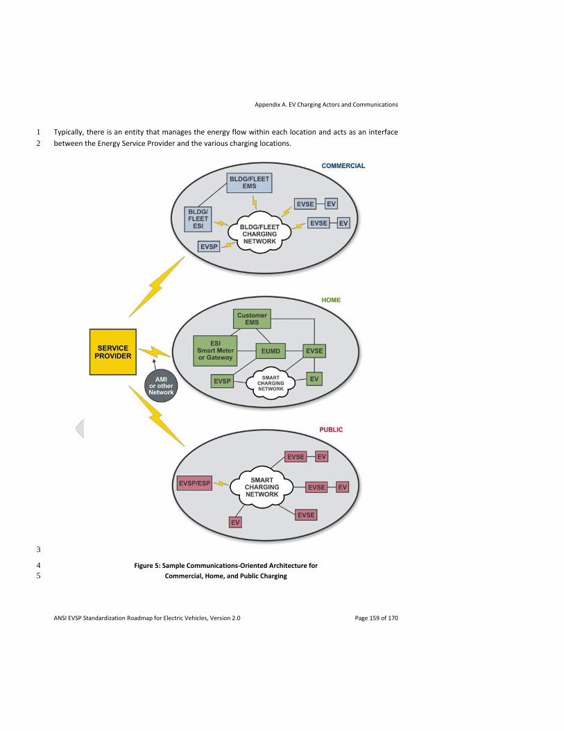
Appendix A. EV Charging Actors and Communications
ANSI EVSP Standardization Roadmap for Electric Vehicles, Version 2.0 Page 159 of 170
Typically, there is an entity that manages the energy flow within each location and acts as an interface 1
between the Energy Service Provider and the various charging locations. 2
3
Figure 5: Sample Communications‐Oriented Architecture for 4 Commercial, Home, and Public Charging 5
Appendix A. EV Charging Actors and Communications
ANSI EVSP Standardization Roadmap for Electric Vehicles, Version 2.0 Page 160 of 170
In a home, an Energy Management System (EMS) could act as an analog of a building EMS and control 1
all the energy loads in the home, including EVs. While the external communication with the Energy 2
Service Provider uses an Energy Services Interface (ESI), communication between the EMS and the 3
internal charging infrastructure takes place via a Home Area Network (HAN). Optionally, an EV Services 4
Provider may manage the EV portion of the load, leaving the EMS to handle the remaining loads such as 5
air‐conditioning. 6
In the case of a commercial/industrial building, an EMS may be the entity managing the energy flow. It 7
communicates with the ESP via a standard ESI, and with the building's charging infrastructure via some 8
internal communications mechanism (e.g., BACnet). 9
For public charging stations, an EV Services Provider manages a network of EVSEs and provides charging 10
availability to EV drivers. The EVSP communicates with the ESP using a standard protocol such as 11
OpenADR 2.0 or ESPI, and may act as an aggregator, providing a single communication point with the 12
ESP for all the EVSEs in its purview. Creating and/or harmonizing standards specific to public charging 13
communication is desirable in order to provide services such as finding and reserving charging stations. 14
A.6 Actors 15
EV 16
Electric Vehicle 17
EV Driver 18
A driver or operator of an EV. The term EV driver is used to include anybody who requests authorization 19
to charge the EV (e.g., a fleet operator). 20
Electric Vehicle Supply Equipment (EVSE) 21
The conductors, the electric vehicle connectors, attachment plugs, and all other fittings, devices, power 22
outlets, or apparatuses installed specifically for the purpose of delivering energy from the premises 23
wiring to the electric vehicle. 24
Energy Service Provider (ESP) 25
An entity that generates, transmits, and distributes electrical power (e.g., a utility). In this document, 26
this term is also used to describe an Energy Retailer. An Energy Retailer is a seller of electricity and 27
related services such as customer service and billing, but is not involved in generation, transmission and 28
distribution. 29
Energy Management System (EMS) 30
A logical entity that manages energy consumption in a home/building/premises. This may be controlled 31
by a consumer (e.g., homeowner, premises owner) or an Energy Service Provider (e.g., a utility). 32
Appendix A. EV Charging Actors and Communications
ANSI EVSP Standardization Roadmap for Electric Vehicles, Version 2.0 Page 161 of 170
End Use Measurement Device (EUMD) 1
A revenue‐grade meter responsible for directly measuring energy delivered to an EV. The physical form, 2
location and ownership of the EUMD may be unique for different applications. 3
EV Services Provider (EVSP a/k/a EVSE Host Management Services) 4
An entity that provides services related to EV charging, such as locating charging stations, reserving 5
charging stations, subscription/fee‐based charging, status/alerts via smartphones, etc. This entity may 6
be an Energy Service Provider (such as a utility), a municipality, or an independent company providing 7
these services. 8
A.7 Sample Types of Communications Between Actors 9
EV – EV Driver 10
Communication between an EV and its driver or operator. Although the user interface and possibly 11
much of the communication involved may be proprietary, it may be useful to standardize a basic level of 12
communication that covers alerts and status. 13
EV – EVSE 14
Communication between an EV and the EVSE to which it is physically connected. This communication is 15
used for authentication, authorization of charging, metering and sign‐off by the EV of metering data; 16
communicating EV data such as state of charge (SOC) to the EVSE/EMS/grid; selection of charging plan 17
and time based on available tariff information obtained from the EVSE, etc. Depending on whether the 18
EV, the EVSE or both are intelligent, the communication to the grid may be performed by either (or 19
both) of them. 20
EV – Energy Service Provider 21
The EV and the Energy Service Provider may communicate directly with each other (in certain scenarios 22
such as when an EVSE acts as a PLC‐ZigBee bridge or via OEM owned telematics link) and exchange 23
messages related to pricing/tariffs, demand response, metering, etc. 24
EV – EMS 25
An EMS may control multiple devices that act as loads or sources in the home/building/premises. 26
Communication between the EV and the EMS provides the EMS with information about the EV charging 27
requirements, real‐time status, errors, etc. The EMS may control charging parameters such as start/stop 28
time and amount of energy dispensed. It may also act as an interface for the Energy Service Provider, by 29
acting on demand response messages, adapting charging schedules based on the grid status, and 30
managing reverse energy flow to the grid (V2G). 31
Appendix A. EV Charging Actors and Communications
ANSI EVSP Standardization Roadmap for Electric Vehicles, Version 2.0 Page 162 of 170
EV – EV Services Provider 1
An EV may communicate with an EV Services Provider and exchange messages related to state of charge 2
(SOC), selection of charging parameters based on tariffs, demand response, etc. 3
EV Driver – EVSE 4
The interaction between an EV driver and an EVSE will probably take place via a user interface or via an 5
EMS or EV Services Provider 6
EVSE – Energy Service Provider 7
The EVSE and the Energy Service Provider may communicate directly with each other and exchange 8
messages related to pricing/tariffs, demand response, metering, etc. 9
EVSE – EV Services Provider 10
EVSEs are managed by an EV Services Provider. The communication involved relates to status, 11
diagnostics, reservations, pricing, access control, metering data, demand response, etc. 12
EMS – Energy Service Provider 13
Communication between the EMS and an Energy Service Provider may include handling of demand 14
response, DER (distributed energy resources, e.g., for energy flow from the EV to the grid), pricing/tariff 15
related information, etc. 16
EUMD – EV Services Provider/Energy Services Provider 17
The billing entity, whether it is the EVSP or the ESP, may communicate with the EUMD in order to collect 18
EV energy consumption data and apply billing parameters or tariffs. In certain scenarios, the EUMD data 19
might also be used to validate program compliance (e.g., demand response or ancillary services). 20
EV Services Provider – Energy Service Provider 21
Communication between an EV Services Provider and an Energy Service Provider may include demand 22
response and pricing related messaging, as well as charging records. 23
EV Services Provider – EMS 24
An EMS or home/building/premises automation system may query charging records from the EV 25
Services Provider that manages the charging stations at the home/building/premises. Also, charging 26
constraints such as time of charge, energy to be dispensed, and access control may need to be 27
communicated to EVSEs via the EV Services Provider. 28

Appendix A. EV Charging Actors and Communications
ANSI EVSP Standardization Roadmap for Electric Vehicles, Version 2.0 Page 163 of 170
EV Services Provider – EV Services Provider 1
Two EV Services Providers may communicate directly or via a third party when the customer of one 2
provider charges at a station managed by the other. This communication would include authentication, 3
authorization, accounting, and settlement. 4
5
6

ANSI EVSP Standardization Roadmap for Electric Vehicles, Version 2.0 Page 164 of 170
1
2
3
4
5
6
7
[this page intentionally left blank] 8
Appendix B. Glossary of Acronyms and Abbreviations
ANSI EVSP Standardization Roadmap for Electric Vehicles, Version 2.0 Page 165 of 170
Appendix B. Glossary of Acronyms and Abbreviations 1
See also Appendix A. EV Charging Actors and Communications and the ANSI EVSP Roadmap Standards 2
Compendium. 3
AC – Alternating Current 4
AEV – Battery‐Powered All Electric Vehicle 5
ANCE (Mexico) – La Asociación Nacional de Normalización y Certificación del Sector Eléctrico, A.C. 6
CANENA – Council for Harmonization of Electrotechnical Standards of the Nations of the Americas 7
CEN – European Committee for Standardization 8
CENELEC – European Committee for Electrotechnical Standardization 9
DC – Direct Current 10
DER – Distributed Energy Resource 11
DOE – U.S. Department of Energy 12
EPRI – Electric Power Research Institute 13
EREV – Extended Range Electric Vehicle 14
ESO – European Standards Organization 15
EV – Electric Vehicle 16
EVSE – Electric Vehicle Supply Equipment 17
FMVSS – Federal Motor Vehicle Safety Standards 18
GTR – Global Technical Regulation 19
HAN – Home Area Network 20
HEV – Hybrid Electric Vehicle 21
IAEI – International Association of Electrical Inspectors 22
IBC® – International Building Code® 23
ICC – International Code Council 24
IEC – International Electrotechnical Commission 25
Appendix B. Glossary of Acronyms and Abbreviations
ANSI EVSP Standardization Roadmap for Electric Vehicles, Version 2.0 Page 166 of 170
IEEE – Institute of Electrical and Electronics Engineers 1
IFC® – International Fire Code® 2
IgCCTM – International Green Construction CodeTM 3
IMC® – International Mechanical Code® 4
IRC® – International Residential Code® for One‐ and Two‐Family Dwellings 5
ISO – International Organization for Standardization 6
IZC® – International Zoning Code® 7
NAN – Neighborhood Area Network 8
NEC® – NFPA 70®, the National Electrical Code® 9
NECA – National Electrical Contractors Association 10
NEMA – National Electrical Manufacturers Association 11
NFPA – National Fire Protection Association 12
NHTSA – National Highway Traffic Safety Administration 13
OEM – Original Equipment Manufacturer 14
PEV – Plug‐in Electric Vehicle 15
PHEV – Plug‐in Hybrid Electric Vehicle 16
PLC – Power Line Communication 17
RESS – Rechargeable Energy Storage System 18
RFID – Radio‐Frequency Identification 19
RPF – Reverse Power Flow 20
SAE – SAE International 21
SGIP – Smart Grid Interoperability Panel 22
SDO – Standards Development Organization 23
UL – Underwriters Laboratories, Inc. 24
UNECE – United Nations Economic Commission for Europe 25

Appendix B. Glossary of Acronyms and Abbreviations
ANSI EVSP Standardization Roadmap for Electric Vehicles, Version 2.0 Page 167 of 170
V2G – Vehicle to Grid 1
V2H – Vehicle to Home 2
V2L – Vehicle to Load 3
V2V – Vehicle to Vehicle 4
WP.29 – World Forum for Harmonization of Vehicle Regulations5

ANSI EVSP Standardization Roadmap for Electric Vehicles, Version 2.0 Page 168 of 170
1
2
3
4
5
6
7
[this page intentionally left blank] 8
9

ANSI EVSP Standardization Roadmap for Electric Vehicles, Version 2.0 Page 169 of 170
1
2
3
4
5
6
7
[this page intentionally left blank] 8
9
10

ANSI EVSP Standardization Roadmap for Electric Vehicles, Version 2.0 Page 170 of 170
1
2
3
4
5
6
7
[this page intentionally left blank] 8
9
10