rmu2 linux logic controller user manual - john morris … · 3 quick-start ... how to cross-compile...
TRANSCRIPT

RMU2
Linux Logic Controller
User Manual
Control & Information Technology Group
134 W Rio Robles Drive
San Jose, CA 95134
Main: 408.750.0300
Fax: 408.750.2990
Manual Rev. 09
03/2010
RMU2 User Manual
2 of 2 © MKS Instruments CIT Products 2005, All rights reserved
Copyright
This manual and the software described in it are copyrighted with all rights reserved. Under the copyright laws, this manual and software may not be copied, in whole or part, without the prior written consent of MKS Instruments. The same proprietary and copyright notices must be affixed to any permitted copies as were affixed to the original. This exception does not allow copies to be made for others whether or not sold, but all of the materials purchased may be sold, given, or loaned to another person. Under the law, copying includes translating into another language or format. © MKS Instruments - CIT Products Group, 2010
Preface
About this manual This manual is designed to serve as a guideline for the installation, setup, operation and basic maintenance of the RMU device. The information contained within this manual, including product specifications, is subject to change without notice. Please observe all safety precautions and use appropriate procedures when handling the RMU product and its related software.

RMU2 User Manual
3 of 3 © MKS Instruments CIT Products 2005, All rights reserved
Table of Contents
1 INTRODUCTION............................................................................................................................................ 6
1.1 CONVENTIONS USED IN THIS USER MANUAL........................................................................................ 6
2 INSTALLATION AND SETUP ....................................................................................................................... 7
2.1 SHIPPING BOX CONTENTS.................................................................................................................... 7 2.2 RMU DESCRIPTION .............................................................................................................................. 7 2.3 MECHANICAL DESCRIPTION.................................................................................................................. 8 2.4 INSTALLATION........................................................................................................................................ 8 2.5 WIRING AND HARDWARE CONFIGURATION .......................................................................................... 9 2.5.1 Power Supply Wiring ..................................................................................................................... 9 2.5.2 Analog I/O Wiring ......................................................................................................................... 10 2.5.3 Digital I/O Wiring .......................................................................................................................... 11 2.5.4 Combo I/O Wiring......................................................................................................................... 12
2.6 DIGITAL INPUTS................................................................................................................................... 13 2.7 DIGITAL INPUT INTERFACE EXAMPLE ................................................................................................. 14 2.8 DIGITAL OUTPUTS ............................................................................................................................... 14 2.9 DIGITAL OUTPUT INTERFACE EXAMPLE.............................................................................................. 14 2.10 ANALOG INPUTS .................................................................................................................................. 15 2.11 ANALOG OUTPUTS .............................................................................................................................. 15 2.12 SERIAL PORT CONNECTIONS.............................................................................................................. 16 2.12.1 COM1 and COM2 .................................................................................................................... 16 2.12.2 COM3 and COM4 .................................................................................................................... 16
2.13 STANDARD RS232 SERIAL CABLE WITH HANDSHAKING CONNECTION.............................................. 18
3 QUICK-START............................................................................................................................................. 19
3.1 TELNET................................................................................................................................................ 19 3.2 SERIAL CONNECTION.......................................................................................................................... 20 3.3 CONFIGURATION ................................................................................................................................. 20 3.4 BOOTING THE RMU ............................................................................................................................ 20
4 RMU SOFTWARE USER’S GUIDE ............................................................................................................. 21
4.1 SYSTEM COMPONENTS....................................................................................................................... 21 4.1.1 Boot Loader................................................................................................................................... 21 4.1.2 Kernel............................................................................................................................................. 22 4.1.3 The built-in Initrd File System..................................................................................................... 22 4.1.4 JFFS2 ............................................................................................................................................ 23 4.1.5 Compact Flash ............................................................................................................................. 23 4.1.6 Kernel's Modules .......................................................................................................................... 23 4.1.7 Cross Platform Development Tools........................................................................................... 24 4.1.8 Creating my first application ....................................................................................................... 25
4.2 RUN-TIME PLATFORM .......................................................................................................................... 26 4.2.1 Boot procedure ............................................................................................................................. 26 4.2.2 Configuration................................................................................................................................. 26 4.2.3 Storage .......................................................................................................................................... 32
4.3 WEB SERVER ...................................................................................................................................... 34
5 DIO API ........................................................................................................................................................ 34
5.1 DEVICE APIS....................................................................................................................................... 35 5.1.1 Overview........................................................................................................................................ 35 5.1.2 Basic procedures ......................................................................................................................... 36 5.1.3 ASCII Interface ............................................................................................................................. 37 5.1.4 Binary Interface ............................................................................................................................ 37
5.2 FUNCTION DEFINITIONS ...................................................................................................................... 37 5.2.1 Open() ............................................................................................................................................ 37 5.2.2 Close() ........................................................................................................................................... 38 5.2.3 Read() ............................................................................................................................................ 38
RMU2 User Manual
4 of 4 © MKS Instruments CIT Products 2005, All rights reserved
5.2.4 Write() ............................................................................................................................................ 40 5.2.5 Ioctl() .............................................................................................................................................. 42
6 AIO API ........................................................................................................................................................ 43
6.1 BASIC PROCEDURES ........................................................................................................................... 44 6.2 TRANSLATING READS & WRITES ......................................................................................................... 45 6.3 FUNCTION DEFINITIONS ...................................................................................................................... 45 6.3.1 Open() ............................................................................................................................................ 45 6.3.2 Close() ........................................................................................................................................... 46 6.3.3 Read() ............................................................................................................................................ 46 6.3.4 Write() ............................................................................................................................................ 47
6.4 MKSAIO.H ......................................................................................................................................... 48 6.5 SAMPLE CODE .................................................................................................................................... 50
7 MMI API ....................................................................................................................................................... 51
7.1 AT89 API............................................................................................................................................ 51 7.1.1 Function Definitions ..................................................................................................................... 52
7.2 AT89DISPLAY API.............................................................................................................................. 54 7.2.1 Function Definitions ..................................................................................................................... 54
7.3 AT89BUTTONS API ............................................................................................................................ 57 7.3.1 Function Definitions ..................................................................................................................... 57
8 RS-485 ......................................................................................................................................................... 60
APPENDIX A: POSIX FUNCTIONS DESCRIPTION............................................................................................ 61
1. FUNCTION “OPEN” ........................................................................................................................................ 61 2. FUNCTION “CLOSE” ...................................................................................................................................... 65 NAME .............................................................................................................................................................. 65 SYNOPSIS ..................................................................................................................................................... 65 DESCRIPTION ............................................................................................................................................. 65 RETURN VALUE ........................................................................................................................................... 65 ERRORS ......................................................................................................................................................... 65 CONFORMING TO....................................................................................................................................... 65 NOTES............................................................................................................................................................ 65 SEE ALSO ...................................................................................................................................................... 65 3. FUNCTION “READ” ........................................................................................................................................ 66 NAME .............................................................................................................................................................. 66 SYNOPSIS ..................................................................................................................................................... 66 DESCRIPTION ............................................................................................................................................. 66 RETURN VALUE ........................................................................................................................................... 66 ERRORS ......................................................................................................................................................... 66 CONFORMING TO....................................................................................................................................... 66 RESTRICTIONS ........................................................................................................................................... 66 SEE ALSO ...................................................................................................................................................... 66 4. FUNCTION “WRITE”....................................................................................................................................... 67 NAME .............................................................................................................................................................. 67 SYNOPSIS ..................................................................................................................................................... 67 DESCRIPTION ............................................................................................................................................. 67 RETURN VALUE ........................................................................................................................................... 67 ERRORS ......................................................................................................................................................... 67 CONFORMING TO....................................................................................................................................... 67 NOTES............................................................................................................................................................ 67 SEE ALSO ...................................................................................................................................................... 67 5. FUNCTION “IOCTL”........................................................................................................................................ 68 NAME .............................................................................................................................................................. 68 SYNOPSIS ..................................................................................................................................................... 68 DESCRIPTION ............................................................................................................................................. 68
RMU2 User Manual
5 of 5 © MKS Instruments CIT Products 2005, All rights reserved
RETURN VALUE ........................................................................................................................................... 68 ERRORS ......................................................................................................................................................... 68 NOTE............................................................................................................................................................... 68 CONFORMING TO....................................................................................................................................... 68 SEE ALSO ...................................................................................................................................................... 68
APPENDIX B: HOW TO CROSS-COMPILE TCPDUMP ..................................................................................... 69
APPENDIX C: HOW TO CROSS-COMPILE BOA WEB SERVER ...................................................................... 70
SPECIFICATIONS................................................................................................................................................ 71
WARRANTY ......................................................................................................................................................... 74

RMU2 User Manual
6 of 6 © MKS Instruments CIT Products 2005, All rights reserved
1 Introduction The RMU is an open control platform that allows customers to run MKS or customer specific applications in Linux environment. The platform consists of a PowerPC processor, local peripherals, and PCI IO and special function cards. All IO boards communicate using the PCI-104 bus. This manual provides details on the installation and use of this product. The RMU supports at maximum, the following features:
• PowerPC running at 400 MHz, 760 MIPS with support of floating point instructions • 16 MB of on board Flash using the Linux Journaling file system. • On Board compact flash socket for CF type 2 devices for application and data
storage. • 128MB SDRAM • Power Conditioning (18 – 30V) • 4 RS232 interface. (1 port used for diagnostics port, software selectable 485 on 2 of
ports) • 2 independent 10/100 Ethernet ports • USB V1.1 • Up to 96 DIO Points • Up to 64 Analog input points and 32 Output point
1.1 Conventions used in this User Manual
Warning The WARNING sign denotes a hazard to personnel. It calls attention to a procedure, practice, condition, or the like, which, if not correctly performed or adhered to, could result in injury to personnel.
Caution The CAUTION sign higlights information that is important to the safe operation of the RMU, or to the integrity of your files. .
Note THE NOTE SIGN DENOTES IMPORTANT INFORMATION. IT CALLS ATTENTION TO A PROCEDURE, PRACTICE, CONDITION, OR THE LIKE, WHICH IS ESSENTIAL TO HIGHLIGHT.
On screen buttons or menu items appear in bold and cursive. Example: Click OK to save the settings. Keyboard keys appear in brackets. Example: [ENTER] and [CTRL] Pages with additional information about a specific topic are cross-referenced within the text.

RMU2 User Manual
7 of 7 © MKS Instruments CIT Products 2005, All rights reserved
2 Installation and Setup
2.1 Shipping Box Contents
• RMU Module • Power mating connector
2.2 RMU Description
The RMU is a compact, Linux controller with integrated I/O and peripherals. The CPU will have Linux kernel 2.4.x. All required kernel drivers are preloaded to support current hardware requirements. There are 5 RMU packages, each to accommodate the number of I/O slots (0-4) Each I/O card to have a D-sub 37 connector, top and bottom. Each cards connectors to be in the same location, so enclosure cutouts are the same for a DIDO or AIAO card. The front of the RMU provides all operators interface and status indicators. The figure below describes the features on the front panel. These items include I/O indicators, fuses, IP address switches, and diagnostic ports. The following mechanical drawing is a typical 2 expansion slot model.
Figure 1 RMU Description
24 Volt Power Connecter
Compact Flash Bay
User Programmable Display
Digital IO Connector 37 Pin D-Sub
Digital IO Connector 37 Pin D-Sub
User Defined Function Buttons
USB Port
LAN Ports
Reset Button
Status LEDs
Digital IO Expansion Module
Analog IO Expansion Module

RMU2 User Manual
8 of 8 © MKS Instruments CIT Products 2005, All rights reserved
2.3 Mechanical Description
The following mechanical drawing describes a typical 2 slot configuration. Additional slots will cause the unit to be wider but will not change height or depth. Addition mechanical information for other configurations can be obtained through your local MKS representative
Figure 2 Mechanical Description
Note ALL DIMENSIONS ARE METRIC
2.4 Installation
The RMU mounts on a standard 35mm DIN rail system. Make sure there is sufficient side clearance for ventilation, to maintain an ambient operating temperature of 0°C to 50°C.
Figure 3 RMU DIN Rail Mounting

RMU2 User Manual
9 of 9 © MKS Instruments CIT Products 2005, All rights reserved
2.5 Wiring and Hardware Configuration
Ethernet and I/O cables are available from a variety of industrial sources. See table below for orderable I/O mating connectors. Example mating connector for the RMU IO is provided in Table 1
Table 1 Mating IO Connector Information
Description MFG Part Number
37-pin D-SUB with Shell (Terminal Block Connections)
Phoenix 2300986
Caution In order to guarantee proper operation and prevent damage to the product insure that the chasis ground is properly attached
for the application.
Warning
Follow all applicable electrical codes when mounting and wiring any electrical device.
2.5.1 Power Supply Wiring
Connect an external 18-30 VDC power supply to the 3-terminal Power Connector. The connector should be wired according to the labeling on the RMU.
Pin Signal 1 18-30 VDC
2 Chassis GND
3 GND
Figure 4 Power Terminal Block
The manufacturer and ordering part number for the RMU power terminal block connector is described in Table 3.
Table 2 Terminal Block Information
Description MFG Part Number
3-pin Terminal Block Weidmuller 1625620000
1 2 3

RMU2 User Manual
10 of 10 © MKS Instruments CIT Products 2005, All rights reserved
2.5.2 Analog I/O Wiring
The RMU analog expansion board has two D-Sub 37 connectors used to access the I/O points. Each I/O card type has unique pin assignments; the assignments for the analog card are shown in the following figures.
AI1
+
AG
ND
AI2
+
AG
ND
AI3
+
AG
ND
AI4
+
AG
ND
AI5
+
AG
ND
AI6
+
AG
ND
AI7
+
AG
ND
AI8
+
AG
ND
AG
ND
+1
5V
+1
5V
1 2 3 4 5 6 7 8 9 10 11 12 13 14 15 16 17 18 19
20 21 22 23 24 25 26 27 28 29 30 31 32 33 34 35 36 37A
I1-
AG
ND
AI2
-
AG
ND
AI3
-
AG
ND
AI4
-
AG
ND
AI5
-
AG
ND
AI6
-
AG
ND
AI7
-
AG
ND
AI8
-
AG
ND
-1
5V
-1
5V
Analog Inputs – Differential Mode
Top Side Connector
AI1
AG
ND
AI2
AG
ND
AI3
AG
ND
AI4
AG
ND
AI5
AG
ND
AI6
AG
ND
AI7
AG
ND
AI8
AG
ND
AG
ND
+1
5V
+1
5V
1 2 3 4 5 6 7 8 9 10 11 12 13 14 15 16 17 18 19
20 21 22 23 24 25 26 27 28 29 30 31 32 33 34 35 36 37
AI9
AG
ND
AI1
0
AG
ND
AI1
1
AG
ND
AI1
2
AG
ND
AI1
3
AG
ND
AI1
4
AG
ND
AI1
5
AG
ND
AI1
6
AG
ND
-1
5V
-1
5V
Analog Inputs – Single Ended Mode
Top Side Connector
AO
1
AG
ND
AO
2
AG
ND
AO
3
AG
ND
AO
4
AG
ND
AO
5
AG
ND
AO
6
AG
ND
AO
7
AG
ND
AO
8
AG
ND
AG
ND
+1
5V
+1
5V
1 2 3 4 5 6 7 8 9 10 11 12 13 14 15 16 17 18 19
20 21 22 23 24 25 26 27 28 29 30 31 32 33 34 35 36 37
NC
NC
NC
NC
NC
NC
NC
NC
NC
NC
NC
NC
NC
NC
NC
NC
-15
V
-15
V
Analog Outputs
Bottom Side Connector
Note ALL ANALOG POWER COMES FROM AN INTERNAL POWER CONVERTER. EXTERNAL PINS FOR +/- 15 VOLTS SHOULD BE USED AS REFERENCE ONLY. SUPPLIES HAVE LIMITED POWER AND SHOULD NOT BE USED TO DRIVE EXTERNAL LOADS.

RMU2 User Manual
11 of 11 © MKS Instruments CIT Products 2005, All rights reserved
2.5.3 Digital I/O Wiring
The RMU digital expansion board has two D-Sub 37 connectors used to access the I/O points. The +24V power must be supplied by an external source via these connectors. Each I/O card type has unique pin assignments; the assignments for the digital card are shown in the following figures. All the 24 GNDs are one net.
+2
4 I
N
DIO
1
24
GN
D
+2
4 I
N
DIO
2
24
GN
D
+2
4 I
N
DIO
3
24
GN
D
+2
4 I
N
DIO
4
24
GN
D
+2
4 I
N
DIO
5
24
GN
D
DIO
6
NC
24
GN
D
+2
4 I
N
1 2 3 4 5 6 7 8 9 10 11 12 13 14 15 16 17 18 19
20 21 22 23 24 25 26 27 28 29 30 31 32 33 34 35 36 37
DIO
7
24
GN
D
+2
4 I
N
DIO
8
24
GN
D
+2
4 I
N
DIO
9
24
GN
D
+2
4 I
N
DIO
10
24
GN
D
+2
4 I
N
DIO
11
24
GN
D
DIO
12
NC
NC
Re
fSe
l
Digital Top Side Connector
Source/Sink Select for Digital Top Connector
Sink/Source Select Sourcing Input/Sinking Output Short Pin 18 to 37 Sinking Input/Sourcing Output Short Pin 19 to 37
+2
4 I
N
DIO
13
24
GN
D
+2
4 I
N
DIO
14
24
GN
D
+2
4 I
N
DIO
15
24
GN
D
+2
4 I
N
DIO
16
24
GN
D
+2
4 I
N
DIO
17
24
GN
D
DIO
18
NC
24
GN
D
+2
4 I
N
1 2 3 4 5 6 7 8 9 10 11 12 13 14 15 16 17 18 19
20 21 22 23 24 25 26 27 28 29 30 31 32 33 34 35 36 37
DIO
19
24
GN
D
+2
4 I
N
DIO
20
24
GN
D
+2
4 I
N
DIO
21
24
GN
D
+2
4 I
N
DIO
22
24
GN
D
+2
4 I
N
DIO
23
24
GN
D
DIO
24
NC
NC
Re
fSe
l
Digital Bottom Side Connector
Source/Sink Select for Digital Bottom Connector
Sink/Source Select Sourcing Input/Sinking Output Short Pin 18 to 37 Sinking Input/Sourcing Output Short Pin 19 to 37

RMU2 User Manual
12 of 12 © MKS Instruments CIT Products 2005, All rights reserved
2.5.4 Combo I/O Wiring
The Combo I/O Expansion Card has two 37-pin D-Sub connectors used to access the I/O points. The +24V power must be supplied by an external source via these connectors. The +/- 15V power is supplied by an internal converter. The pin assignments are shown in the following tables. All the 24 GNDs are one net.
+2
4 I
N
+2
4 I
N
24
GN
D
+2
4 I
N
24
GN
D
24
GN
D
+2
4 I
N
DIO
6
24
GN
D
+2
4 I
N
DIO
7
24
GN
D
+2
4 I
N
DIO
8
24
GN
D
DIO
9
NC
24
GN
D
+2
4 I
N
1 2 3 4 5 6 7 8 9 10 11 12 13 14 15 16 17 18 19
20 21 22 23 24 25 26 27 28 29 30 31 32 33 34 35 36 37
DIO
12
24
GN
D
DIO
11
+2
4 I
N
DIO
10
24
GN
D
DIO
5
24
GN
D
DIO
4
+2
4 I
N
DIO
3
24
GN
D
DIO
2
+2
4 I
N
DIO
1
NC
NC
Re
fSe
l
Combo Top Side Connector
Source/Sink Select for Combo Top Connector
Sink/Source Select Sourcing Input/Sinking Output Short Pin 18 to 37 Sinking Input/Sourcing Output Short Pin 19 to 37
DIO
13
24
GN
D
+2
4 I
N
DIO
14
24
GN
D
NC
NC
Re
fSe
l
24
IN
-15
V
-15
V
AI
8
AI4
AI
7
AI
3
AG
ND
AO
2 -
AO
2 +
AG
ND
1 2 3 4 5 6 7 8 9 10 11 12 13 14 15 16 17 18 19
20 21 22 23 24 25 26 27 28 29 30 31 32 33 34 35 36 37
24
GN
D
DIO
15
+2
4 I
N
DIO
16
24
GN
D
NC
+ 2
4 I
N
+ 2
4 I
N
24
GN
D
+1
5 V
+1
5 V
AI
6
AI
2
AI
5
AI
1
AG
ND
AO
1 -
AO
1 +
Combo Bottom Side Connector
Source/Sink Select for Combo Bottom Connector
Sink/Source Select Sourcing Input/Sinking Output Short Pin 18 to 37 Sinking Input/Sourcing Output Short Pin 19 to 37

RMU2 User Manual
13 of 13 © MKS Instruments CIT Products 2005, All rights reserved
DIO
13
24
GN
D
+2
4 I
N
DIO
14
24
GN
D
NC
NC
Re
fSe
l
24
IN
-15
V
-15
V
AI4
-
AI4
+
AI3
-
AI3
+
AG
ND
AO
2 -
AO
2 +
AG
ND
1 2 3 4 5 6 7 8 9 10 11 12 13 14 15 16 17 18 19
20 21 22 23 24 25 26 27 28 29 30 31 32 33 34 35 36 37
24
GN
D
DIO
15
+2
4 I
N
DIO
16
24
GN
D
NC
+ 2
4 I
N
+ 2
4 I
N
24
GN
D
+1
5 V
+1
5 V
AI2
-
AI2
+
AI1
-
AI1
+
AG
ND
AO
1 -
AO
1 +
Combo Bottom Side Connector (Differential)
Source/Sink Select for Combo Bottom Connector
Sink/Source Select Sourcing Input/Sinking Output Short Pin 18 to 37 Sinking Input/Sourcing Output Short Pin 19 to 37
Note ALL ANALOG POWER COMES FROM AN INTERNAL POWER CONVERTER. EXTERNAL PINS FOR +/- 15 VOLTS SHOULD BE USED AS REFERENCE ONLY. SUPPLIES HAVE LIMITED POWER AND SHOULD NOT BE USED TO DRIVE EXTERNAL LOADS
2.6 Digital Inputs
Digital I/O can be configured as either sinking or sourcing I/O. Each input circuit includes an indicator LED in series with the detection opto-coupler. The opto-coupler isolates the processor from the inputs. The inputs require 1.5mA in order to turn on.
Figure 4 Sourcing Input
Figure 5 Sinking Input

2.7 Digital Input Interface Example
Below is an example of how to use the digital input interface for both the sinking and sourcing hardware configurations. The digital I/O circuitry is powered from an external +24-volt power source via the I/O connector.
DIO1
24V GND
RMU DIO
DIO1
+24V
RMU DIO
Figure 6 Sourcing Input Figure 7 Sinking Input
2.8 Digital Outputs
The individual outputs will support up to a 200 mA load per channel. Each output is thermally protected against short-circuiting (500 mA typically) and includes under voltage protection. The output Fault State is accessible through software. External Schottky diodes are provided for output transient protection and each I/O point is protected with a self-resetting poly fuse rated for 500 mA. Outputs default to the OFF condition during power up and processor reset conditions. The figure below shows the output circuitry.
24_GND
+24V
DIO XOutputDriver
Figure 8 Digital Output
2.9 Digital Output Interface Example
Below is an example of how to interface with the digital outputs for both the sinking and sourcing hardware configurations. The digital I/O circuitry is again powered from an external +24-volt power source via the I/O connector.
DIO1
+24V
RMU DIO
+
-
DIO1
24V GND
RMU DIO
+
-
Sinking Output Sourcing Output
Figure 9
RMU2 User Manual
15 of 2 © MKS Instruments CIT Products 2005, All rights reserved
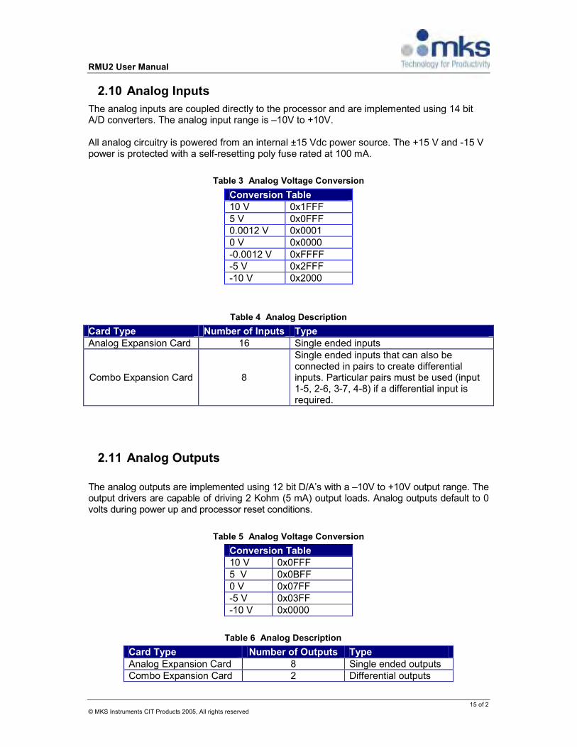
2.10 Analog Inputs
The analog inputs are coupled directly to the processor and are implemented using 14 bit A/D converters. The analog input range is –10V to +10V. All analog circuitry is powered from an internal ±15 Vdc power source. The +15 V and -15 V power is protected with a self-resetting poly fuse rated at 100 mA.
Table 3 Analog Voltage Conversion
Conversion Table
10 V 0x1FFF 5 V 0x0FFF 0.0012 V 0x0001 0 V 0x0000 -0.0012 V 0xFFFF -5 V 0x2FFF -10 V 0x2000
Table 4 Analog Description
Card Type Number of Inputs Type
Analog Expansion Card 16 Single ended inputs
Combo Expansion Card 8
Single ended inputs that can also be connected in pairs to create differential inputs. Particular pairs must be used (input 1-5, 2-6, 3-7, 4-8) if a differential input is required.
2.11 Analog Outputs
The analog outputs are implemented using 12 bit D/A’s with a –10V to +10V output range. The output drivers are capable of driving 2 Kohm (5 mA) output loads. Analog outputs default to 0 volts during power up and processor reset conditions.
Table 5 Analog Voltage Conversion
Conversion Table
10 V 0x0FFF 5 V 0x0BFF 0 V 0x07FF -5 V 0x03FF -10 V 0x0000
Table 6 Analog Description
Card Type Number of Outputs Type
Analog Expansion Card 8 Single ended outputs Combo Expansion Card 2 Differential outputs

RMU2 User Manual
16 of 3 © MKS Instruments CIT Products 2005, All rights reserved
2.12 Serial Port Connections
The RMU2 contains 4 total serial communication ports. Connector is standard D-Sub 9 pin male. COM1 and COM2 are RS232 only. COM3 and COM4 are RS232/RS485 Software selectable.
2.12.1 COM1 and COM2
COM1 and COM2 only support simple RS232 protocol with no hardware flow control.
2.12.1.1 Simple RS232 serial port connector’s pin-out
Pin RS232 Function Description 2 RXD Receive Data (a.k.a RD, Rx) 3 TXD Transmit Data (a.k.a TD, Tx)
5 SGND Ground 1, 4, 6-9 NC No Connect
2.12.2 COM3 and COM4
COM3 and COM4 are RS232/RS485 Software Selectable. RS232 supports hardware flow control. RS485 supports both half and full-duplex mode. NOTES: HW Flow Control for RS232 is only supported on COM 3 and COM4.
2.12.2.1 RS232 serial port connector with HW flow control pin-out
(DTR/DSR signals are not supported and are shorted together internally)
Pin RS232 Function Description 1 DCD – No Connect Data Carrier Detect (No Connect) 2 RXD Receive Data (a.k.a RD, Rx)
3 TXD Transmit Data (a.k.a TD, Tx) 4 DTR Data Terminal Ready (shorted to pin 6 internally) 5 SGND Ground 6 DSR Data Set Ready (shorted to pin 4 internally) 7 RTS Request To Send 8 CTS Clear To Send 9 RI – No Connect Ring Indicator (No Connect)

RMU2 User Manual
17 of 4 © MKS Instruments CIT Products 2005, All rights reserved
2.12.2.2 RS485 Half-Duplex port pin-outs
For RS485 half-duplex mode: pin2and pin3 (TxD) need to be tied together. Pin7, pin8 (RxD) also need to be tied together. Pin RS485HD Function Description 1 NC No Connect 2 RS485- Data Output (Need to short to pin 3 externally)
3 RS485- Data Output (Need to short to pin 2 externally) 4 NC Short to pin 6 internally 5 GND Signal Ground 6 NC Short to pin 4 internally 7 RS485+ Data Input (Need to short to pin 8 externally) 8 RS485+ Data Input (Need to short to pin 7 externally) 9 NC No Connect
2.12.2.3 RS485 Full-Duplex port pin-outs
Pin RS485FD Function Description 1 NC No Connect 2 RxD- Data Input-
3 TxD- Data Output- 4 NC Short to pin 6 internally 5 GND Signal Ground 6 NC Short to pin 4 internally 7 TxD+ Data Onput+ 8 RxD+ Data Input+ 9 NC No Connect
RMU2 User Manual
18 of 5 © MKS Instruments CIT Products 2005, All rights reserved
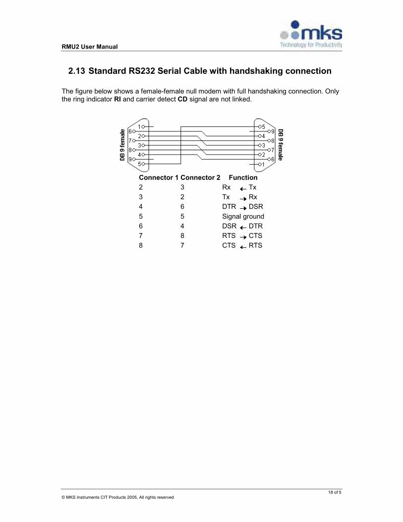
2.13 Standard RS232 Serial Cable with handshaking connection
The figure below shows a female-female null modem with full handshaking connection. Only the ring indicator RI and carrier detect CD signal are not linked.
Connector 1 Connector 2 Function
2 3 Rx Tx
3 2 Tx Rx
4 6 DTR DSR
5 5 Signal ground
6 4 DSR DTR
7 8 RTS CTS
8 7 CTS RTS
RMU2 User Manual
19 of 6 © MKS Instruments CIT Products 2005, All rights reserved
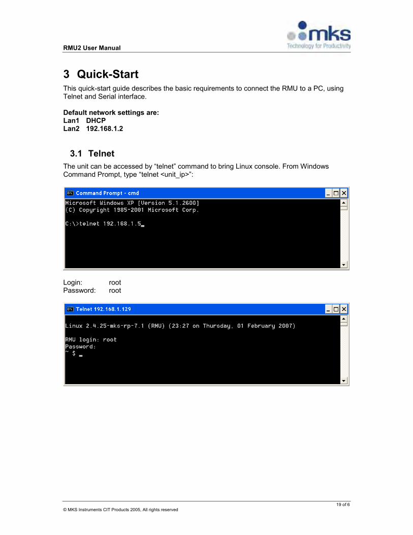
3 Quick-Start This quick-start guide describes the basic requirements to connect the RMU to a PC, using Telnet and Serial interface. Default network settings are: Lan1 DHCP Lan2 192.168.1.2
3.1 Telnet
The unit can be accessed by “telnet” command to bring Linux console. From Windows Command Prompt, type “telnet <unit_ip>”:
Login: root Password: root

RMU2 User Manual
20 of 7 © MKS Instruments CIT Products 2005, All rights reserved
3.2 Serial Connection
Basic connections to the RMU consist of a null modem connection to COM 1 and power.
• Power up RMU by attaching power connector with 24VDC source, 1A. • Attach a null modem cable to RMU COM1 port and your PC.
3.3 Configuration
The RMU's console is accessed through the PC RS232 serial Interface. Any terminal program will work; Hyperterminal is used in this documentation.
Table 9 Serial Configuration
Parameter Value
Baudrate 115200 Data bits 8 Parity None Stop bits 1
3.4 Booting the RMU
Plug the power cable into the unit to start the boot process. Once the System has booted log in to Linux, the user is “root” and the password is “root”. Users can use terminal program such as Microsoft® HyperTerminal or Tera Term Pro to communicate to the diagnostics port of the RMU (on Linux boxes minicomm, c-kermit, cu, etc)
Note NOTE THAT SETTINGS CAN BE OVERWRITTEN BY CONFIGURATION FILES FROM APPLICATION PARTITION (SEE BELOW).

RMU2 User Manual
21 of 8 © MKS Instruments CIT Products 2005, All rights reserved
4 RMU Software User’s Guide The RMU contains sixteen megabytes of FLASH memory. The first six megabytes contain:
1. Boot Loader (UBoot) 2. Linux Kernel (version 2.4.25) (compressed) 3. Initrd File System and data files image (compressed)
The next ten megabytes contain the Journaling Flash File System (JFFS2) that is used to store application programs and data.
4.1 System Components
4.1.1 Boot Loader
The major functions of the boot loader are: 1. Initialize the basic board fundamentals peripherals. 2. Hold fundamental system parameters, such as MAC address and part number. 3. Interact with the console (RMU COM1) to start the boot process 4. Uncompress and copy the Linux Kernel to the RAM 5. Uncompress and copy the Initrd File system to the RAM to be used as the root file
system (“/”). The Initrd File system will be stored in RAM as a ram disk file system /dev/ram0.
6. Start the Kernel. The user interface to U-Boot consists of a command line interrupter, much like a Linux shell prompt. When connected via a serial line you can interactively enter commands and see the results. After power on, the initial u-boot prompt looks similar to this: U-Boot 1.1.3 (Aug 15 2005 - 15:08:45) CPU: MPC5200 v2.1 at 396 MHz Bus 132 MHz, IPB 66 MHz, PCI 33 MHz Board: Motorola MPC5200 (IceCube) I2C: 85 kHz, ready DRAM: 128 MB FLASH: 16 MB PCI: Bus Dev VenId DevId Class Int 00 1d 1057 5809 0680 00 01 08 0458 0228 0e00 00 01 09 0458 0228 0e00 00 01 0a 0458 0228 0e00 00 01 0b 0458 0228 0e00 00 01 0c 10ec 8139 0200 00 00 1e 3388 0021 0604 ff In: serial Out: serial Err: serial Net: FEC ETHERNET, RTL8139#0 IDE: Bus 0: OK Device 0: not available

RMU2 User Manual
22 of 9 © MKS Instruments CIT Products 2005, All rights reserved
Device 1: not available Type "run flash_nfs" to mount root filesystem over NFS Hit any key to stop autoboot: 0 => <INTERRUPT> =>
To access the U-boot prompt, stop Linux Kernel from booting by hitting any key before the timer prompt expires. help, printenv, setenv, saveenv and run commands are available at U-boot shell. Use saveenv command to save changed environment variables => saveenv Saving Environment to Flash... Un-Protected 1 sectors Erasing Flash... done Erased 1 sectors Writing to Flash... done Protected 1 sectors =>
Having a network connection on your boot loader is very convenient during development. All networked boards can download and boot the same kernel image from a centralized server, so user only needs to update a single copy of kernel on the server and not each board individually.
4.1.2 Kernel
The kernel is the core of the system; it controls all resources and processes. When the kernel starts, it determines which of the root file system is configured. The system can be brought up with one of two root file systems: initrd +JFFS2 or the Compact Flash. In both cases, the kernel will start the init process and read the inittab for more startup instructions.
4.1.3 The built-in Initrd File System
Initrd is a ram based file system that consists of the following folders:
bin dev lib tmp sbin etc mnt proc usr var

RMU2 User Manual
23 of 10 © MKS Instruments CIT Products 2005, All rights reserved
The initrd is a volatile entity; therefore it's not the place for permanent settings. Any changes or additions to the file system will be lost when the system is rebooted. Permanent settings should use the Flash memory file system (JFFS2) which is mounted by the system startup to the /mnt/ffs VFS location. The initrd startup code creates “hooks” to the JFFS2 file system allowing permanent configuration.
4.1.4 JFFS2
Journaling Flash File System (JFFS) version 2 is a standard file system for flash memory; it comes as a complementary sub file system to the initrd. JFFS basic directory hierarchy includes the etc and lib sub directories. Customization configuration files are under etc subdirectory. Additional kernel modules are under lib subdirectory. Unnecessary modules may be removed. The rest of the JFFS sub file system can be used as the user's application play ground. Important files under etc:
• network.conf • rc.application • rc.preconfig
4.1.5 Compact Flash
The RMU supplied a self contained unit, and as such include all the necessary tools and applications for development and maintenance. In addition, the RMU supports a compact flash that can be used for development or additional data storage. An alternative way to run the system is to start the system from the removable Compact Flash. When the RMU boots-up it can be easily manipulated to continue the bootstrap sequence from the Compact Flash. In this case, the compact flash is used as the system root file system.
4.1.6 Kernel's Modules
All supported devices are included in the monolithic part of the RMU kernel. Other drivers can be loaded into the kernel space by demand. These the kernel's modules are supplied as part of the bundle and can be located on the JFFS sub file system, under /lib/modules/2.4.25-mks-rp-XX/. It was intentionally placed on the JFFS to allow the removal of unneeded modules to allow additional storage space. Modules can be loaded or removed with insmod and rmmod utilities, respectively. All current loaded modules and their dependencies are under /proc/modules file and can be seen with command “cat /proc/modules” The following example illustrates how to access Windows 2000/XP/2003 file share. It is assumed that Windows computer has:
1. Shared directory called “RMU” 2. IP address: 192.168.1.3 3. Local user “rmu” with password “rmu” which has permissions to
access the share CIFS driver must be loaded to enable Windows file share connectivity.

RMU2 User Manual
24 of 11 © MKS Instruments CIT Products 2005, All rights reserved
CIFS can be loaded with the below command sets:
insmod cifs.o mkdir /mnt/winxp mount -t cifs cifs /mnt/winxp -o unc=//192.168.1.3/RMU,user=rmu,pass=rmu
Note that module needs to be loaded only once. If it is required to mount more Windows file shares, it is not necessary to run “insmod cifs.o” command. To check if the module is loaded, use “lsmod” command:
lsmod Module Size Used by Tainted: GF rtl8150 8432 0 (unused) cifs 167256 0 (unused) usb-storage 58992 0 (unused)
Use “rmmod” to remove a module:
rmmod cifs
4.1.7 Cross Platform Development Tools
To build applications to run on the RMU, acquire the DENX Software Engineering Embedded Linux Development Kit (ELDK) 3.1.1. The ELDK provides cross compilation tools to allow the user to develop RMU applications on ELDK supported host platforms. The ELDK 3.1.1 Tools can be obtained from DENX at http://www.denx.de. To correctly interface with the RMU kernel and the associated runtime libraries, it is imperative that the application code be build with ELDK 3.1.1 tools. The relevant architecture for the RMU is the ppc_82xx. gcc version. Pay attention to use the right set of tools. Make sure the ppc_82xx binary directory is on the system PATH, and export the CROSS_COMPILE environment variable to point to the ppc_82xx- tools package. Below is the link to obtain ELDK:
http://www.denx.de/wiki/view/DULG/ELDKAvailability Alternative direct links to ISO image on different mirrors:
1. ftp://mirror.switch.ch/mirror/eldk/eldk/3.1.1-2005-06-07/ppc-linux-x86/iso/ppc-2005-06-07.iso
2. http://mirror.switch.ch/ftp/mirror/eldk/eldk/3.1.1-2005-06-07/ppc-linux-x86/iso/ppc-2005-06-07.iso
RMU2 User Manual
25 of 12 © MKS Instruments CIT Products 2005, All rights reserved
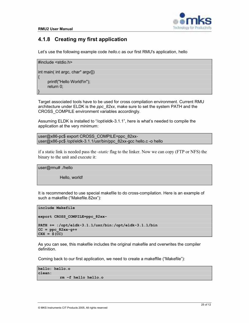
4.1.8 Creating my first application
Let’s use the following example code hello.c as our first RMU's application, hello
#include <stdio.h> int main( int argc, char* argv[]) printf("Hello World!\n"); return 0;
Target associated tools have to be used for cross compilation environment. Current RMU architecture under ELDK is the ppc_82xx, make sure to set the system PATH and the CROSS_COMPILE environment variables accordingly. Assuming ELDK is installed to “/opt/eldk-3.1.1”, here is what’s needed to compile the application at the very minimum:
user@x86-pc$ export CROSS_COMPILE=ppc_82xx- user@x86-pc$ /opt/eldk-3.1.1/usr/bin/ppc_82xx-gcc hello.c -o hello
if a static link is needed pass the -static flag to the linker. Now we can copy (FTP or NFS) the
binary to the unit and execute it:
user@rmu# ./hello Hello, world!
It is recommended to use special makefile to do cross-compilation. Here is an example of such a makefile (“Makefile.82xx”): include Makefile export CROSS_COMPILE=ppc_82xx- PATH += :/opt/eldk-3.1.1/usr/bin:/opt/eldk-3.1.1/bin CC = ppc_82xx-g++ CXX = $(CC)
As you can see, this makefile includes the original makefile and overwrites the compiler definition. Coming back to our first application, we need to create a makeffile (“Makefile”): hello: hello.o clean: rm –f hello hello.o

RMU2 User Manual
26 of 13 © MKS Instruments CIT Products 2005, All rights reserved
Now we can compile the binary for x86 platform: make clean; make
Or for RMU: make clean; make -f Makefile.82xx
In order to get application to start when unit boots, its startup command needs to be added to “/mnt/ffs/etc/rc.application” file. Please, see section 4.2.2.3 for more details. Please, see Appendix B and C for cross-compiling 3rd party packages with “configure” script.
4.2 Run-time platform
The run time platform refers to the system running from flash; it may use the compact flash but only as an external storage, and not as the system root file system. Usually it implies a stable and finalize product. This is the default factory setup. The components involved are the Linux kernel, the initialization ram-disk (InitRD), and the JFFS2 as a dynamic but non volatile file system. The kernel and InitRD are supplied as a solid binary. The JFFS2 comes with default content. User can choose to remove or change the JFFS' content, and what to do with the rest of the storage place.
4.2.1 Boot procedure
Default settings configure the bootloader to invoke the Linux OS automatically. The Linux OS will run with console on COM1 and default network configuration. The defaults are: console 115200bps, 8N1, no flow control, network LAN1(eth0) set by a DHCP, LAN2(eth1) 192.168.1.2. Whether it is the console or a telnet session the login shell will be activated (the console login shell mask CTRL-C). It is highly recommended to login first via the serial console to make sure that the system is configured as needed before switching to the network connection. Use telnet to log into the system, and ftp or tftp to transfer files to/from the RMU. The factory settings for the development platform's user and password are: root and root, respectively.
4.2.2 Configuration
4.2.2.1 Serial Port Configuration
RMU supports standard “stty” (setserial) to view/configure the serial port parameters. Below are some common stty commands (all examples below are issued on COM3)

RMU2 User Manual
27 of 14 © MKS Instruments CIT Products 2005, All rights reserved
To see the current configuration for the port: # stty –F /dev/ttyS2 -g 100:3:8000cb11:5c7:3:1c:7f:15:4:1:0:0:0:0:17:12:1a:11:13:16:15:0:0:0:0:0:0:0:0:0:0:0:0:0:0:0 #stty –F /dev/ttyS2 -a speed 115200 baud; rows 0; columns 0; intr = ^C; quit = ^\; erase = ^?; kill = ^U; eof = ^D; eol = <undef>; eol2 = <undef>; start = ^Q; stop = ^S; susp = ^Z; rprnt = ^R; werase = ^W; lnext = ^V; flush = ^U; min = 1; time = 0; -parenb -parodd cs8 hupcl -cstopb cread clocal crtscts -ignbrk -brkint -ignpar -parmrk -inpck -istrip -inlcr -igncr icrnl -ixon -ixoff -iuclc -ixany -imaxbel opost -olcuc -ocrnl onlcr -onocr -onlret -ofill -ofdel nl0 cr0 tab0 bs0 vt0 ff0 isig icanon iexten -echo echoe echok -echonl -noflsh -xcase -tostop -echoprt echoctl echoke
Set speed: #stty –F /dev/ttyS2 speed 115200
Enable echo: #stty –F /dev/ttyS2 echo
Disable echo: #stty –F /dev/ttyS2–echo
Enable cooked mode: #stty –F /dev/ttyS2 -raw #stty –F /dev/ttyS2 cooked
Enable HW FlowControl: #stty –F /dev/ttyS2 crtscts
Disable HW FlowControl: #stty –F /dev/ttyS2 -crtscts
Allow input to be received: #stty –F /dev/ttyS2 cread
Enable SW FlowControl: #stty –F /dev/ttyS2 ixon
Enable sending start/stop chars: #stty –F /dev/ttyS2 ixoff
Disable SW FlowControl: #stty –F /dev/ttyS2 –ixon
Disable sending start/stop chars: #stty –F /dev/ttyS2–ixoff
Enable raw connection: #stty –F /dev/ttyS2 -cooked
#stty –F /dev/ttyS2 raw

RMU2 User Manual
28 of 15 © MKS Instruments CIT Products 2005, All rights reserved
4.2.2.2 Initialization
The kernel starts the init process with configuration files from InitRD rootfs. "Hooks" were created with the system startup procedure, allowing the customization of the system initialization. The described flow below is part of the solid initrd image, except for the hooks which will be emphasized. The environment variable FFS will be used as the pointer to the location of the configuration files on the mounted JFFS sub file system.
• Init process starts and follows the inittab instructions. • Default configuration is loaded e.g.; IP addresses, location of the JFFS ($FFS),
services to run. (/etc/rc.config) • The second MAC address is set. It's striped from the kernel command line. The first
MAC address is set by the u-boot. • Set the loopback interface • Mount the sub-systems proc, usbfs and jffs • [hook] if exist, invoke the script $FFS/etc/rc.preconfig • [hook] if exist, load the configuration file $FFS/etc/network.conf • [hook] if exist, invoke the script $FFS/etc/rc.network • [hook] if exist, load the configuration file $FFS/etc/services.conf
Table 10 system's Initialization hooks
The hook Purpose
$FFS/etc/rc.preconfig [script] This should be the place to make all system adjustment before any action has been taken. For instance create soft/hard links, manipulate initrd files such as the password file, loads modules etc.
$FFS/etc/network.conf [configuration] This should be the place to make the basic network configuration.
HOSTNAME Unit network host name ETH0 Network configuration for eth0.
Possible values are (including quotes): •“dhcp”
•“auto” •“<ip_address>” •“<ip_address> netmask <mask>”
Some examples:
1. ETH0=”dhcp” 2. ETH0=”auto” 3. ETH0=”192.168.1.5” 4. ETH0=”10.10.2.12 netmask 255.255.0.0”

RMU2 User Manual
29 of 15 © MKS Instruments CIT Products 2005, All rights reserved
Note: the values must be quoted.
ETH1 Network configuration for eth1. Format is the same as for ETH0
GATEWAY Network default gateway. This setting is ignored if either one of eth0 or eth1 is set to “dhcp”
DNS List of one or more DNS servers Example: DNS="192.168.1.1 10.10.1.1"
$FFS/etc/rc.network [script] This is the callback that gets executed at the end of main network configuration script. It could be used to do any network oriented actions, such as interface manipulation and/or setting up advanced routing, notifying needed applications etc.
$FFS/etc/rc.ip_change [script] This script is a callback for IP address change. This could happen when e.g. DHCP server gives unit the new IP address. Such callback could be used to notify needed application(s) and/or to display the new IP address on 4-digit display. Interface name is supplied as the first parameter to this callback and this NIC identifies the one with changed IP.
$FFS/etc/services.conf [configuration] The place to enable or disable any of the services.
SYSLOGD Defines whether “syslogd” service needs to be started at boot up. Service is started only if this variable is set to lowercase “y”.
XINETD Defines whether “xinetd” service needs to be started at boot up. Service is started only if this variable is set to lowercase “y”. Warning: if you disable this service, both telnet and ftp servers will no longer be accessible.
PORTMAP Defines whether “portmap” service needs to be started at boot up. Service is started only if this variable is set to lowercase “y”.
4.2.2.3 Network
The system has a default network configuration, [see /etc/rc.config]. However the RMU supplied with a template $FFS/etc/network.conf which sets the following settings. ETH0 (LAN 1) factory setting
Parameter RMU Setting
IP-Address of eth0 DHCP

RMU2 User Manual
30 of 17 © MKS Instruments CIT Products 2005, All rights reserved
ETH1 (LAN2) factory setting Parameter RMU Setting
IP-Address of eth1 192.168.1.2 Subnet Mask 255.255.255.0 Default Gateway N/A
IF configuration file is missing, the units revert to the below network settings: ETH0 (LAN1) default setting
Parameter RMU Setting
IP-Address of eth0 192.168.1.5 Subnet Mask 255.255.255.0 Default Gateway None
ETH1 (LAN2) default setting
Parameter RMU Setting
IP-Address of eth1 172.21.232.5 Subnet Mask 255.255.0.0 Default Gateway 172.21.100.1
4.2.2.3.1 Interactive configuration
When unit is inaccessible from the network and/or user interface does not provide a functionality to change the IP address, special “net” command from serial console can be used to setup primary network interface – LAN1. LAN2 (eth1) is not supported. User needs to login via serial console and execute the following command at prompt:
net <ip_address> This will permanently set LAN1 to specified <ip_address>. The full syntax of net command is
the following: net <ip_address> [ <netmask> [ <default gateway> ] ] where: <ip_address> is one of •dhcp •auto •fixed IP address <netmask> - subnet mask <default gateway> - default gateway for the current network.
Note that <netmask> and <gateway> parameters are optional. Network change is taken into effect immediately. No restart is required. If executed without arguments, net command shows the current configuration and current IP addresses. Below are some examples of how net command can be used (note that “user@rmu#” represents command prompt and must not be typed in):
1. Just change the IP address and leave default gateway unchanged:
RMU2 User Manual
31 of 18 © MKS Instruments CIT Products 2005, All rights reserved
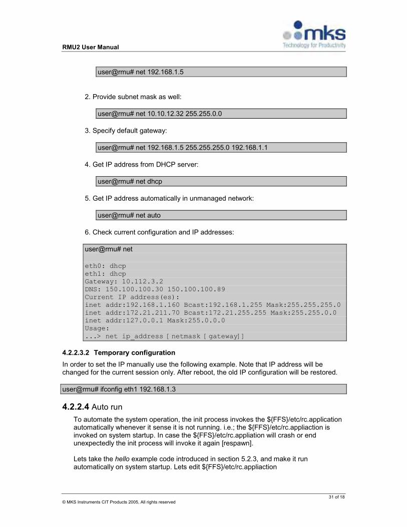
user@rmu# net 192.168.1.5
2. Provide subnet mask as well:
user@rmu# net 10.10.12.32 255.255.0.0
3. Specify default gateway:
user@rmu# net 192.168.1.5 255.255.255.0 192.168.1.1
4. Get IP address from DHCP server:
user@rmu# net dhcp
5. Get IP address automatically in unmanaged network:
user@rmu# net auto
6. Check current configuration and IP addresses:
user@rmu# net
eth0: dhcp eth1: dhcp Gateway: 10.112.3.2 DNS: 150.100.100.30 150.100.100.89 Current IP address(es): inet addr:192.168.1.160 Bcast:192.168.1.255 Mask:255.255.255.0 inet addr:172.21.211.70 Bcast:172.21.255.255 Mask:255.255.0.0 inet addr:127.0.0.1 Mask:255.0.0.0 Usage: ...> net ip_address [netmask [gateway]]
4.2.2.3.2 Temporary configuration
In order to set the IP manually use the following example. Note that IP address will be changed for the current session only. After reboot, the old IP configuration will be restored.
user@rmu# ifconfig eth1 192.168.1.3
4.2.2.4 Auto run
To automate the system operation, the init process invokes the $FFS/etc/rc.application automatically whenever it sense it is not running. i.e.; the $FFS/etc/rc.appliaction is invoked on system startup. In case the $FFS/etc/rc.appliation will crash or end unexpectedly the init process will invoke it again [respawn]. Lets take the hello example code introduced in section 5.2.3, and make it run automatically on system startup. Lets edit $FFS/etc/rc.appliaction

RMU2 User Manual
32 of 19 © MKS Instruments CIT Products 2005, All rights reserved
user@rmu# vi /mnt/ffs/etc/rc.application
Here is the content of /mnt/ffs/etc/rc.application
#!/bin/sh /mnt/ffs/hello
The result of this will be a constant printout of Hello World, because the hello will finish running and the $FFS/etc/rc.application will exhausted, and the init process will bring it up again and again. To run it once use the hold shell command in the script, this way the rc.application script will still run and will be respawn only if it crashes unwontedly.
#!/bin/sh /mnt/ffs/hello >/dev/null 2>&1 & hold
Save the file and reboot the system, by enter the command reboot or cycle the RMU power to reboot the RMU. You will observe the Hello World output on reboot, but only once. If you would kill the rc.application, you should observe the Hello World output again. It is also recommended to start the application by /bin/conti.sh script. This script will restart the application in case it crashed:
#!/bin/sh conti.sh /mnt/ffs/hello >/dev/null 2>&1 & hold
4.2.3 Storage
4.2.3.1 JFFS
The JFFS file system is designed to manage Flash in the most efficient way, it’s wearable oriented to keep the flash life cycle longer. It tolerates brutal and unexpected power cut. It’s mounted over the /dev/mtdblock3 MTD device. The JFFS contains basic configuration templates and kernel's modules. User can choose to use those supplied modules or to remove them and free JFFS storage space. The JFFS file system is mounted automatically by the init process from the InitRD's configuration file instructions. The Factory associated configuration files are under the $FFS/etc sub-directory. The Factory associated kernel's external modules are under $FFS/lib/modules sub-directory. The rest of the JFFS available memory is for customer's application use.
4.2.3.2 Compact Flash
In the Runtime platform the compact flash is used for general storage. It is not mounted automatically, it should be mounted manually, or by adjusting the hooks to do it automatically. Usually a new compact flash comes preformatted with a FAT file system.

RMU2 User Manual
33 of 20 © MKS Instruments CIT Products 2005, All rights reserved
4.2.3.2.1 Accessing CompactFlash
From within the RMU, CompactFlash is accessible as “/dev/hda”. This command mounts Compact flash (assuming a single partition) into file system:
user@rmu# mount /dev/hda1 /mnt/data
Example for expected console's messages for the ext3 file system
hda: hda1 hda: hda1 kjournald starting. Commit interval 5 seconds EXT3 FS 2.4-0.9.19, 19 August 2002 on ide0(3,1), internal journal EXT3-fs: mounted filesystem with ordered data mode. user@rmu#
To check is the compact flash already mounted to /mnt/data:
user@rmu# if mountpoint -q /mnt/data; then echo “Yes”; else echo “No”; fi Yes
4.2.3.2.2 Formatting CompactFlash
As mentioned above, most of brand-new CompactFlash cards come pre-formatted as FAT. In order to format it to EXT3, simply unmount it (if mounted) and run mkfs.etx3:
user@rmu# umount /mnt/data user@rmu# mkfs.ext3 /dev/hda1 user@rmu# tune2fs -i 0 -c -1 /dev/hda1
4.2.3.3 USB
Basic USB support is included monolithically in the Linux kernel. But to support an USB as a storage device, a particular kernel module should be loaded. The kernel modules are supplied as an external package located on the JFFS sub file system. User has the flexibility to remove these modules for storage space if found not useful. Preloading the usb storage driver
insmod usb-storage.o
Expected console messages
Initializing USB Mass Storage driver... usb.c: registered new driver usb-storage

RMU2 User Manual
34 of 21 © MKS Instruments CIT Products 2005, All rights reserved
USB Mass Storage support registered.
Messages similar to below are observed when an USB device is inserted:
hub.c: new USB device 0-1, assigned address 6 hub.c: USB hub found hub.c: 1 port detected hub.c: new USB device 0-1.1, assigned address 7 scsi0 : SCSI emulation for USB Mass Storage devices Vendor: Corsair Model: Flash Voyager Rev: 1.00 Type: Direct-Access ANSI SCSI revision: 02 Attached scsi removable disk sda at scsi0, channel 0, id 0, lun 0 SCSI device sda: 507904 512-byte hdwr sectors (260 MB) sda: Write Protect is off sda: sda1
The following message signifies that an USB storage was detected but the driver was not loaded into the kernel. Use insmod procedure to look for the usb-storage module from /proc/modules.
hub.c: USB hub found hub.c: 1 port detected hub.c: new USB device 0-1.1, assigned address 3 usb.c: USB device 3 (vend/prod 0x67b/0x2517) is not claimed by any active driver.
Example for loading a disk-on-key
user@rmu# mkdir /mnt/usb user@rmu# mount /dev/sda1 /mnt/usb/
4.3 Web Server
RMU does not have a web server application in the files system as a default. However, any web server application, such as BOA, may be loaded onto internal or external flash. BOA web server documentation can be found at http://www.boa.org/. BOA web server needs to be configured and started. See Appendix C for the procedure of how to create a binary for RMU. See section [TBD] for details about how to add applications to startup sequence.
5 DIO API The Digital IO Expansion Module is a PCI104 compatible device. The PCI interface for the Digital IO board is PCI 2.1 compatible. The PCI Connector is PC104 Compliant. The slot addresses for the PCI bus are determined by jumper settings. The RMU Digital IO Module’s Driver is included with the Linux distribution or is available upon request. The API for the Driver is standard POSIX format.

RMU2 User Manual
35 of 22 © MKS Instruments CIT Products 2005, All rights reserved
The I/O module is configurable; each of the modules has Digital IO points can be configured as inputs or outputs. Units can be configured for sink or source, a jumper is used to activate the I/O configuration on the connector pins. See section for DIDO connection.
PCI Controller
DIO 0-11D-SUB 37pin
DIO 12-23D-SUB 37pin
Digital Output
Drivers (2)
Digital InputOpto(3)
PCI Bus
33MHz
Digital InputOpto(3)
Digital Output
Drivers (2)
5.1 Device APIs
5.1.1 Overview
The API utilizes the standard POSIX interface to provide the user access to the devices functionality. As a POSIX compliant API, the DIO driver supports the standard operations: open(), close(), read(), write() and ioctl(). The use of open(), close(), read() and write() doesn’t rely on any explicit definitions, it relies only on the standard POSIX definition standard. In order to use the ioctl(), an explicit protocol definition needs to be declared; it’s done in the form of include file, which describes and defines the type of commands available. The DIO are accessed via the VFS character device node. Its major should be 240. The DIO supports two interfaces: ASCII and Binary. Both have the same basic functionalities. The later includes some enhancements, such as get the previous output IOs states when setting a new ones and getting a timestamp indication with the read response. More on these enhancements are shown below. The RMU supports up to four DIO cards. The cards are accessed via the special files:
• /dev/mksdio[0-3] (non-blocking ASCII reads would be used to poll the IO) • /dev/mksbio[0-3] (blocking ASCII reads is interrupt change of state based) • /dev/mksbiob[0-3] (blocking and non-blocking binary reads is interrupt change of
state based)
RMU2 User Manual
36 of 23 © MKS Instruments CIT Products 2005, All rights reserved
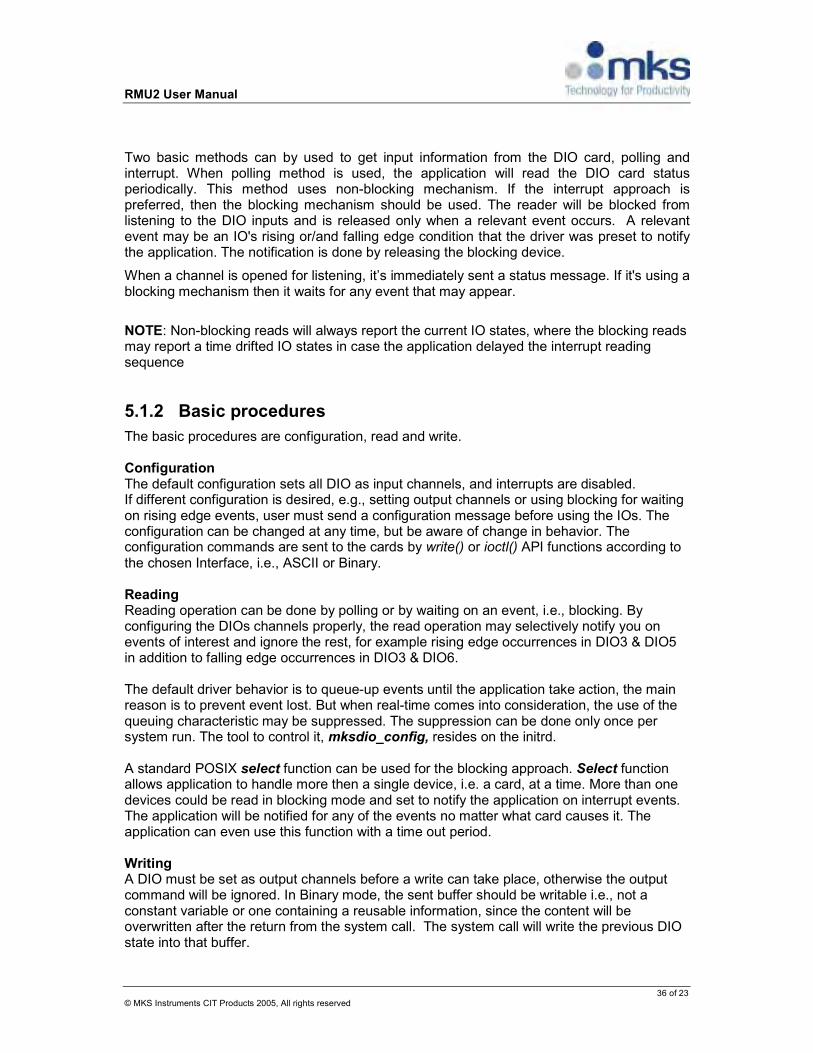
Two basic methods can by used to get input information from the DIO card, polling and interrupt. When polling method is used, the application will read the DIO card status periodically. This method uses non-blocking mechanism. If the interrupt approach is preferred, then the blocking mechanism should be used. The reader will be blocked from listening to the DIO inputs and is released only when a relevant event occurs. A relevant event may be an IO's rising or/and falling edge condition that the driver was preset to notify the application. The notification is done by releasing the blocking device.
When a channel is opened for listening, it’s immediately sent a status message. If it's using a blocking mechanism then it waits for any event that may appear.
NOTE: Non-blocking reads will always report the current IO states, where the blocking reads may report a time drifted IO states in case the application delayed the interrupt reading sequence
5.1.2 Basic procedures
The basic procedures are configuration, read and write. Configuration The default configuration sets all DIO as input channels, and interrupts are disabled. If different configuration is desired, e.g., setting output channels or using blocking for waiting on rising edge events, user must send a configuration message before using the IOs. The configuration can be changed at any time, but be aware of change in behavior. The configuration commands are sent to the cards by write() or ioctl() API functions according to the chosen Interface, i.e., ASCII or Binary. Reading Reading operation can be done by polling or by waiting on an event, i.e., blocking. By configuring the DIOs channels properly, the read operation may selectively notify you on events of interest and ignore the rest, for example rising edge occurrences in DIO3 & DIO5 in addition to falling edge occurrences in DIO3 & DIO6. The default driver behavior is to queue-up events until the application take action, the main reason is to prevent event lost. But when real-time comes into consideration, the use of the queuing characteristic may be suppressed. The suppression can be done only once per system run. The tool to control it, mksdio_config, resides on the initrd. A standard POSIX select function can be used for the blocking approach. Select function allows application to handle more then a single device, i.e. a card, at a time. More than one devices could be read in blocking mode and set to notify the application on interrupt events. The application will be notified for any of the events no matter what card causes it. The application can even use this function with a time out period. Writing A DIO must be set as output channels before a write can take place, otherwise the output command will be ignored. In Binary mode, the sent buffer should be writable i.e., not a constant variable or one containing a reusable information, since the content will be overwritten after the return from the system call. The system call will write the previous DIO state into that buffer.
RMU2 User Manual
37 of 24 © MKS Instruments CIT Products 2005, All rights reserved
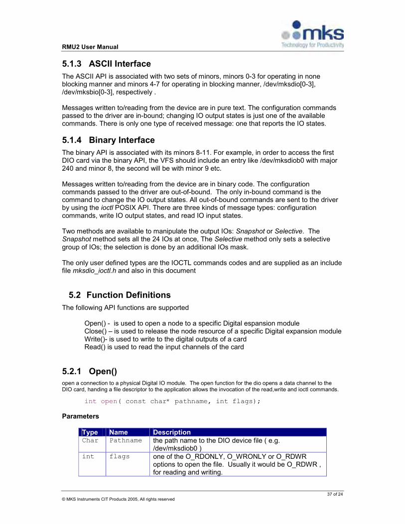
5.1.3 ASCII Interface
The ASCII API is associated with two sets of minors, minors 0-3 for operating in none blocking manner and minors 4-7 for operating in blocking manner, /dev/mksdio[0-3], /dev/mksbio[0-3], respectively . Messages written to/reading from the device are in pure text. The configuration commands passed to the driver are in-bound; changing IO output states is just one of the available commands. There is only one type of received message: one that reports the IO states.
5.1.4 Binary Interface
The binary API is associated with its minors 8-11. For example, in order to access the first DIO card via the binary API, the VFS should include an entry like /dev/mksdiob0 with major 240 and minor 8, the second will be with minor 9 etc. Messages written to/reading from the device are in binary code. The configuration commands passed to the driver are out-of-bound. The only in-bound command is the command to change the IO output states. All out-of-bound commands are sent to the driver by using the ioctl POSIX API. There are three kinds of message types: configuration commands, write IO output states, and read IO input states. Two methods are available to manipulate the output IOs: Snapshot or Selective. The Snapshot method sets all the 24 IOs at once, The Selective method only sets a selective group of IOs; the selection is done by an additional IOs mask. The only user defined types are the IOCTL commands codes and are supplied as an include file mksdio_ioctl.h and also in this document
5.2 Function Definitions
The following API functions are supported Open() - is used to open a node to a specific Digital espansion module
Close() – is used to release the node resource of a specific Digital expansion module Write()- is used to write to the digital outputs of a card Read() is used to read the input channels of the card
5.2.1 Open()
open a connection to a physical Digital IO module. The open function for the dio opens a data channel to the DIO card, handing a file descriptor to the application allows the invocation of the read,write and ioctl commands.
int open( const char* pathname, int flags);
Parameters
Type Name Description Char Pathname the path name to the DIO device file ( e.g.
/dev/mksdiob0 ) int flags one of the O_RDONLY, O_WRONLY or O_RDWR
options to open the file. Usually it would be O_RDWR , for reading and writing.

RMU2 User Manual
38 of 25 © MKS Instruments CIT Products 2005, All rights reserved
Return Value
Type Values Int • The file descriptor if successful
• -1 if an error occurred.
REMARK: use to open both ASCII and Binary interface, the device name will associated the application handler with the ASCII or the Binary interface.
5.2.2 Close()
Close an open connection to a physical Digital IO module. The close function for the dio will close the connection to a DIO module. Release any unnecessary system resources.
int close ( int fd);
Parameters
Type Name Description Char fd file descriptor to be closed
Return Value
Type Values int • 0 if successful
• -1 if an error occurred.
5.2.3 Read()
Read status of the physical Digital IO.
size_t read (int fd, void* buf, size_t count);
Parameters
Type Name Description Int fd file descriptor to read from.
void* buf pointer to buffer in memory that will contain the data + the time indication.[only in binary mode]
Size_t Count number of bytes to be read.
Return Value
Type Values int 8 - indicating the succesful load of 8 bytes into the buffer (Binary Driver)
26 - indicating the succesful load of 26 bytes into the buffer (ASCII Driver) -1 if an error occurred.(Binary Driver) -1 if an error occurred.(ASCII Driver)

RMU2 User Manual
39 of 26 © MKS Instruments CIT Products 2005, All rights reserved
Using ASCII Interface The syntax of the messages is ASCII based and as such it can be manipulated both by a shell script and by an execution. See [Examples].
Message syntax Table: Syntax Description
1 Channel on value 0 Channel off value
The received message contains a 26th characters long, 24 character each per channel, and characters 25-26 are new line followed by a NULL character. The message dumps the IO state into a character string indicating the IO current status. It always dumps all of the 24 channels.
Using Binary Interface Read status of the physical Digital IO as a 32-bit word, or 4 bytes. Each bit represents the DIO status. The DIO occupies the first 24 bits of the message for the 24 DIO channels. the second 32-bit word will be attached to the return data including the event’s time indication, the time indication is the number of 10ms ticks occurred since system startup. The read() operation could be invoked as a blocked or non-blocked operation. This behavior could be controlled by using the ioctl command (MKS_IOCTL_SET_NONBLOCK). Example: Assuming the following LEDS output on the front panel. 2 24 1 0 1 0 0 0 0 0 0 0 0 1 1 1 0 1 1 1 0 0 1 1 0 1 1 23 DIO channels 1-3, 6-7, … , 23-24 are ON DIO channels 4-5,8, …, 20-22 are OFF ASCII : "111001101010000010100011\n\0" Binary: bytes order 1->4 [0x00][0xc5][0x05][0x67] NOTE: few clarifications for the use of blocking mode.
1. The first read will always be none blocked and the return buffer content will be a snapshot of the DIOs states.
2. in order to get notified for any DIO change, the mask for Rising and Falling edges should be adjusted [see ioctl for binary mode and the write for the ASCII mode]

RMU2 User Manual
40 of 27 © MKS Instruments CIT Products 2005, All rights reserved
5.2.4 Write()
Write status of the physical Digital IO module
size_t write ( int fd, const void* buf, size_t len);
Parameters
Type Name Description Int Fd file descriptor to be write to Void* buf pointer to the send data: see how to use ASCII and
Binary interfaces below for more details Size_t len number of bytes to be write. For ASCII 1<=Len<=24, for
Binary 4 or 8 Bytes, see how to use ASCII and Binary interfaces below for more details
Return Value
Type Values Int • Successful in Selective mode: 8 (Binary Driver)
• Successful in Snapshot mode: 4 (Binary Driver) • 27 bytes if Successful (ASCII Driver) • 1 if an error occurred.(Binary Driver) • 1 if an error occurred.(ACSII Driver)
Using the ASCII Interface The syntax of the messages is ASCII's based and as such it can be manipulated both by a shell script and by an execution. See [Examples]. As mentioned above the ASCII interface send all commands in-bounds, an ASCII message is build out of a appended characters each represent an operation, the location of the character implies on which DIO its should be delivered. The first character will be relate to DIO1 the second to the DIO2 etc. therefore a message may be short as a single character or as long as 24 characters, any additional characters append on the end of the message are being ignored.
Message syntax Table: Syntax Description
m Mask interrupt U
unmask interrupt
I Mark as an input O Mark as an output X A don’t care sign 1 Channel on value 0 Channel off value R Filters only rise f Filters only fall
The message can be described as a vector of commands, up to the number of addressable DIOs, which is 24 (per card). Each offset in the vector address to a specific DIO with the
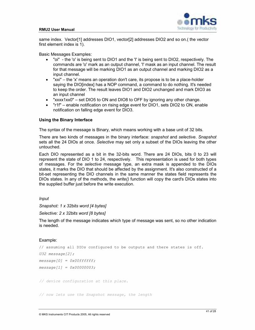
RMU2 User Manual
41 of 28 © MKS Instruments CIT Products 2005, All rights reserved
same index. Vector[1] addresses DIO1, vector[2] addresses DIO2 and so on.( the vector first element index is 1). Basic Messages Examples:
• "oi" - the 'o' is being sent to DIO1 and the 'I' is being sent to DIO2, respectively. The commands are 'o' mark as an output channel, 'I' mask as an input channel. The result for that message will be marking DIO1 as an output channel and marking DIO2 as a input channel.
• "xxi" – the 'x' means an operation don't care, its propose is to be a place-holder saying the DIO[index] has a NOP command, a command to do nothing. It's needed to keep the order. The result leaves DIO1 and DIO2 unchanged and mark DIO3 as an input channel
• "xxxx1xx0" – set DIO5 to ON and DIO8 to OFF by ignoring any other change. • "r1f" – enable notification on rising edge event for DIO1, sets DIO2 to ON, enable
notification on falling edge event for DIO3. Using the Binary Interface The syntax of the message is Binary, which means working with a base unit of 32 bits.
There are two kinds of messages in the binary interface: snapshot and selective. Snapshot sets all the 24 DIOs at once. Selective may set only a subset of the DIOs leaving the other untouched.
Each DIO represented as a bit in the 32-bits word. There are 24 DIOs, bits 0 to 23 will represent the state of DIO 1 to 24, respectively. This representation is used for both types of messages. For the selective message type, an extra mask is appended to the DIOs states, it marks the DIO that should be affected by the assignment. It's also constructed of a bit-set representing the DIO channels in the same manner the states field represents the DIOs states. In any of the methods, the write() function will copy the card's DIOs states into the supplied buffer just before the write execution.
Input
Snapshot: 1 x 32bits word [4 bytes]
Selective: 2 x 32bits word [8 bytes]
The length of the message indicates which type of message was sent, so no other indication is needed.
Example:
// assuming all DIOs configured to be outputs and there states is off.
U32 message[2];
message[0] = 0x00ffffff;
message[1] = 0x00000003;
// device configuration at this place.
// now lets use the Snapshot message, the length

RMU2 User Manual
42 of 29 © MKS Instruments CIT Products 2005, All rights reserved
// was set to 4, the message[1] will be ignored,
// and all the card's DIOs will be effected by the
// value in message[0]. All DIOs should be light up,
// the value will be 0x00ffffff
write (fd, message, 4);
// print the return of the previous states of all DIOs.
printf("pevious states %x\n", message[0]);
// that will set back the DIOs to the initial states
// which is 0x00000000
write (fd, message, 4);
//message[0] and message[1] will be send.
// and DIOs states will be (0x00000003) =
// (message[0](0x00ffffff) & message[1](0x00000003))
write (fd, message, 8);
// message[0] contains the previous value.
Message syntax Table: Syntax Description
1 Channel on value
0 Channel off value
5.2.5 Ioctl()
Control the behavior of the physical Digital IO + the driver behavior.
int ioctl (int fd, int request, …);
Parameters
Type Name Description Int Fd file descriptor to be write to
int Request One of the operations mentioned below. Basically there are two type of operations, a set command and a get command. The set command uses the associated parameters as input data to the driver. The get command uses the associated parameter as a place holder for the output information coming from the driver. Therefore usually the type of parameter associated with a set command will be of type value and the one associated with a get command will be pointer to a place holder that eventually should hold the output for the specific command.
…
The associated parameters, goes with the ioctl command. Each command defines its own associated parameters type and behavior.
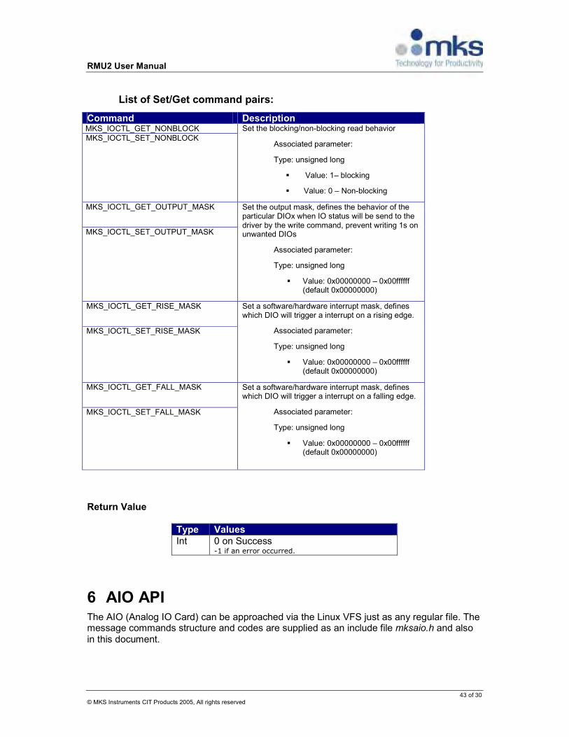
RMU2 User Manual
43 of 30 © MKS Instruments CIT Products 2005, All rights reserved
List of Set/Get command pairs:
Command Description MKS_IOCTL_GET_NONBLOCK MKS_IOCTL_SET_NONBLOCK
Set the blocking/non-blocking read behavior
Associated parameter:
Type: unsigned long
Value: 1– blocking
Value: 0 – Non-blocking
MKS_IOCTL_GET_OUTPUT_MASK
MKS_IOCTL_SET_OUTPUT_MASK
Set the output mask, defines the behavior of the particular DIOx when IO status will be send to the driver by the write command, prevent writing 1s on unwanted DIOs
Associated parameter:
Type: unsigned long
Value: 0x00000000 – 0x00ffffff (default 0x00000000)
MKS_IOCTL_GET_RISE_MASK
MKS_IOCTL_SET_RISE_MASK
Set a software/hardware interrupt mask, defines which DIO will trigger a interrupt on a rising edge.
Associated parameter:
Type: unsigned long
Value: 0x00000000 – 0x00ffffff (default 0x00000000)
MKS_IOCTL_GET_FALL_MASK
MKS_IOCTL_SET_FALL_MASK
Set a software/hardware interrupt mask, defines which DIO will trigger a interrupt on a falling edge.
Associated parameter:
Type: unsigned long
Value: 0x00000000 – 0x00ffffff (default 0x00000000)
Return Value
Type Values Int 0 on Success
-1 if an error occurred.
6 AIO API The AIO (Analog IO Card) can be approached via the Linux VFS just as any regular file. The message commands structure and codes are supplied as an include file mksaio.h and also in this document.

RMU2 User Manual
44 of 31 © MKS Instruments CIT Products 2005, All rights reserved
The AIO input and output differ in their presentation. Input is represented by a 14 bits and output is represented by a 12 bits.
6.1 Basic procedures
The basic procedures are configuration, read and write. The configuration and write operation both use the same message structure in order to pass a command. Read uses a different message structure, it loads each read not only the AIO states but rather all the AIO status information. Configurations The default configuration is 16 single-ended, watchdog interrupt disabled. Mode – can be changed at any time, the options are single-ended (16 channels) and differential mode (8 channels). Watchdog – Internal watchdog can be enabled or disabled. When enabled, it’s up to the application to reset its ticks counter. Reading Each read operation fetches all the information from the AIO card packed into a structure defined in a supplementary include file mksdio.h. It includes all 16 AIO channels' readings, Watchdog information, output readiness indicator flag and the mode flag i.e; whether it's a 16 single-ended or a 8 differential. The AIO channel's read is unprocessed i.e.; 14 bits samples in 2's compliments format (see translate_input function from 5.2). Writing Setting a new value to an AIO is done by creating a message that includes the channel number and the VDC value in [0..4095] range proportionally corresponding to [-10..10] range (see translate_output function from 5.2). The POSIX function to be used for the configuration and writing procedures is the function write with the mksaio_cmd structure. The POSIX function to be used for the reading procedure is the function read with the mksaio_info structure.

RMU2 User Manual
45 of 32 © MKS Instruments CIT Products 2005, All rights reserved
6.2 Translating reads & writes
Translating the reads to the range of +10-(-10)V is done by to following logic.
// the following code can be a one liner macro as well, it is not an optimal code, for matter, of readiness and clarity.
float translate_input(unsigned short orig_val ) float fValue = (float)(orig_val & 0x1FFF) / 819.2 - 10.0; if ((orig_val & 0x2000) == 0) fValue += 10.0; return fValue;
Translating the writes to the 12bits 2's compliments
unsigned short Translate_output( float volts) // boundries check can be added return (unsigned short)((orig_val + 10.0) / 204.8);
6.3 Function Definitions
The following API functions are supported Open() - is used to open a node to a specific Analog expansion module
Close() – is used to release the node resource of a specific Analog expansion module
Write()- is used to write to the digital outputs of a card Read() is used to read the input channels of the card
6.3.1 Open()
open a connection to a physical Analog IO module
int open( const char* pathname, int flags);
Parameters
Type Name Description Char Pathname the path name to the AIO device file ( e.g. /dev/mksaio0
) int flags one of the O_RDONLY, O_WRONLY or O_RDWR
options to open the file. Usually it would be O_RDWR , for reading and writing.

RMU2 User Manual
46 of 33 © MKS Instruments CIT Products 2005, All rights reserved
Return Value
Type Values Int • The file descriptor if successful
• 1 if an error occurred.
Discussion The open function for the AIO opens a data channel to the AIO card, handing a file descriptor to the application allows the invocation of the read and write.
6.3.2 Close()
close an open connection to a physical Analog IO module
int close ( int fd);
Parameters
Type Name Description Char Fd file descriptor to be closed
Return Value
Type Values Int • 0 if successful
• 1 if an error occurred.
Discussion The close function for the dio will close the connection to a AIO module. Release any unnecessary system resources.
6.3.3 Read()
read status of the physical Analog IO and the companion card information.
ssize_t read (int fd, void* buf, size_t count);
Parameters
Type Name Description Int fd file descriptor to read from. Void* Buf pointer to buffer in memory that will contain the data
Of a struct mksaio_info Size_t Count number of bytes to be read.(size of struct mksaio_info)
Return Value
Type Values Int • Sizeof(struct mksaio_info) if
successful • -1 if an error occurred.

RMU2 User Manual
47 of 34 © MKS Instruments CIT Products 2005, All rights reserved
Discussion The definition of the mksaio data structure can be found in the file mksaio.h. Getting Information from the AIO driver should be done by using the mksaio_info structure. This structure contains 4 sections:
• The ADC – a vector of the AIO channel current values in 2's compliment values • Watch_dog – information regarding the watch dog, such as is it enabled or disabled,
time for expiration and indication whether or not an interrupt occurred. The parameters names in the structure are is_int_enabled and is_int_occured respectively.
• DAC – an indicator field that indicates whether AIO card is ready to digest a new output channel update. The parameter's name is is_ready. There is an additional remanded parameter is_int_enabled it's mapped to the same parameter describe under the watch_dog structure.
• AI_conf – mode of operation. i.e; shows the mode a differential mode or a single-ended mode. Its value also implies on the number of valid ADC channels, whether it 8 or 16.
6.3.4 Write()
write status of the physical Analog IO module
ssize_t write ( int fd, const void* buf, size_t len);
Parameters
Type Name Description Int fd file descriptor to be write to
Void* buf pointer to buffer in memory that will contain the data Of struct mksaio_cmd
Size_t Len Sizeof(struct mksaio_cmd)
Return Value
Type Values Int • Sizeof(struct mksaio_cmd) if
successful • -1 if an error occurred.
Discussion The definition of the mksaio data structure can be found in the file mksaio.h. As mentioned above the write function serves both for configuration and for AIO value settings. It's done by sending a command using the mksaio_cmd structure.

RMU2 User Manual
48 of 35 © MKS Instruments CIT Products 2005, All rights reserved
Command Description MKSAIO_CMD_SET_MODE Sets 16 single-emded mode or a 8
differential mode. Options are: MKSAIO_MODE_8_DIFFERENTIAL MKSAIO_MODE_16_SINGLE_ENDED via the structure data.value field.
MKSAIO_CMD_OUTPUT Set output values per channel. Two associated parameters, the channel and the value. The channel is set to the structure's data.output.channel field. The value goes to the data.output.val field. NOTE: the value is a 12bits 2's compliment
MKSAIO_CMD_WD_INT_CTL Enable/Disable the watch dog Options: MKSAIO_ENABLE/MKSAIO_DISABLE Via the structure's data.value field
MKSAIO_CMD_WD_RESET Reset the watchdog, and load the the ticks counter to a new value. The new value is set to the structure's data.value field the value range from 1 to 127, each tick is a 10ms
6.4 MKSAIO.H
#ifndef _MKSAIO_H_ #define _MKSAIO_H_ #ifdef __cplusplus extern "C" #endif /* * List of available commands */ #define MKSAIO_CMD_SET_MODE (1) /* sets single-ended and differential */ #define MKSAIO_CMD_OUTPUT (2) /* Set Output values per channel*/ #define MKSAIO_CMD_WD_INT_CTL (3) /*Enable/Disable watch dog */ #define MKSAIO_CMD_WD_RESET (4) /* Reset the watch dog and enable */ /* it with a selected value*/ /* Options for AI Configurations (MKSAIO_CMD_SET_MODE) */ #define MKSAIO_MODE_8_DIFFERENTIAL (1) #define MKSAIO_MODE_16_SINGLE_ENDED (0) /* General Options (MKSAIO_CMD_WD_INT_CTL,etc.)*/ #define MKSAIO_ENABLE (1) #define MKSAIO_DISABLE (0)

RMU2 User Manual
49 of 36 © MKS Instruments CIT Products 2005, All rights reserved
/* output format to be used by the user's application */ struct mksaio_info unsigned short ADC[16]; struct unsigned char ticks_left:7; // ticks in 10msec unsigned char is_int_enabled:1; unsigned char is_int_occured:1; unsigned char unused:7; watch_dog; struct unsigned char is_int_enabled:1; unsigned char is_ready:1; unsigned char unused:6; DAC; unsigned char AI_conf; ; union mksaio_cmd_data struct unsigned long val:12; unsigned long channel:3; unsigned long unused:17; output; unsigned long value; ; struct mksaio_cmd unsigned long code; union mksaio_cmd_data data; ; #ifdef __cplusplus #endif #endif /*_MKSAIO_H_*/

RMU2 User Manual
50 of 37 © MKS Instruments CIT Products 2005, All rights reserved
6.5 Sample Code
Here is sample code to set analog output to a specific voltage:
/* * nFD – descriptor of open device file (e.g. “/dev/mksaio1”) * nInput – input number to be changed * fValue – voltage (-10..10) */ bool SetAnalogOut(int nFD, int nInput, double fValue) struct mksaio_cmd cmd; double fRange = (fValue + 10.0) * 204.8; cmd.code = MKSAIO_CMD_OUTPUT; cmd.data.output.val = (int)fRange; cmd.data.output.channel = nInput; return sizeof(cmd) == write(nFD, &cmd, sizeof(cmd));
Sample code to switch between singe ended and differential mode:
/* * nFD – descriptor of open device file (e.g. “/dev/mksaio1”) * bDiff – true: differential, false: single ended */ void SetDifferential(int nFD, bool bDiff) struct mksaio_cmd cmd; cmd.code = MKSAIO_CMD_SET_MODE; cmd.data.value = bDiff ? MKSAIO_MODE_8_DIFFERENTIAL :
MKSAIO_MODE_16_SINGLE_ENDED; return sizeof(cmd) == write(nFD, &cmd, sizeof(cmd));
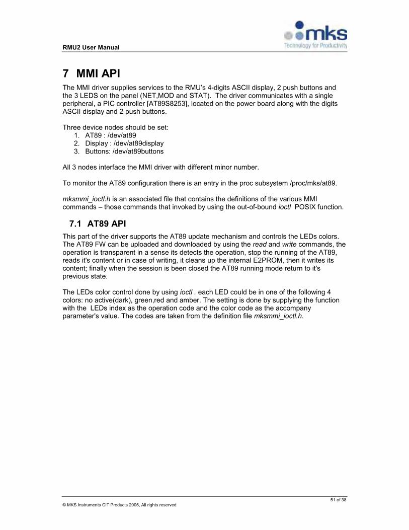
RMU2 User Manual
51 of 38 © MKS Instruments CIT Products 2005, All rights reserved
7 MMI API The MMI driver supplies services to the RMU’s 4-digits ASCII display, 2 push buttons and the 3 LEDS on the panel (NET,MOD and STAT). The driver communicates with a single peripheral, a PIC controller [AT89S8253], located on the power board along with the digits ASCII display and 2 push buttons. Three device nodes should be set:
1. AT89 : /dev/at89 2. Display : /dev/at89display 3. Buttons: /dev/at89buttons
All 3 nodes interface the MMI driver with different minor number. To monitor the AT89 configuration there is an entry in the proc subsystem /proc/mks/at89. mksmmi_ioctl.h is an associated file that contains the definitions of the various MMI commands – those commands that invoked by using the out-of-bound ioctl POSIX function.
7.1 AT89 API
This part of the driver supports the AT89 update mechanism and controls the LEDs colors. The AT89 FW can be uploaded and downloaded by using the read and write commands, the operation is transparent in a sense its detects the operation, stop the running of the AT89, reads it's content or in case of writing, it cleans up the internal E2PROM, then it writes its content; finally when the session is been closed the AT89 running mode return to it's previous state. The LEDs color control done by using ioctl . each LED could be in one of the following 4 colors: no active(dark), green,red and amber. The setting is done by supplying the function with the LEDs index as the operation code and the color code as the accompany parameter's value. The codes are taken from the definition file mksmmi_ioctl.h.

RMU2 User Manual
52 of 39 © MKS Instruments CIT Products 2005, All rights reserved
7.1.1 Function Definitions
The following API functions are supported open() - is used to open a node to the at89 module
close() - is used to release the node resource of a specific to the at89 module write() - is used to write to the fw image to the AT89's E2PROM read() - is used to read the fw image from the AT89's E2PROM
ioctl() – is used to manipulate the LEDS
7.1.1.1 Open()
open a connection to the AT89 device.
int open( const char* pathname, int flags);
Parameters
Type Name Description Char Pathname the path name to the DIO device file ( in this case
/dev/at89 ) int flags one of the O_RDONLY, O_WRONLY or O_RDWR
options to open the file. Usually it would be O_RDWR , for reading and writing.
Return Value
Type Values Int The file descriptor if successful
-1 if an error occurred.
Discussion The open function for the at89 opens a data channel to the AT89 controller.
7.1.1.2 Close()
close an open connection to the AT89 int close ( int fd);
Parameters
Type Name Description Char fd file descriptor to be closed
Return Value
Type Values Int 0 if successful
-1 if an error occurred.

RMU2 User Manual
53 of 40 © MKS Instruments CIT Products 2005, All rights reserved
Discussion Close function for the AT89 module
7.1.1.3 Write()
Writes the incoming data to the AT89's E2PROM sequentially (lseek is not supported) , it transparently handle the erasing of blocks in the E2PROM. No recovery support in case of malfunction after the erase. In this case the session should be closed and repeat the attempt. Any length of data chunk can be used. For optimal operation use chunks of 64 bytes. ssize_t write ( int fd, const void* buf, size_t len);
Parameters
Type Name Description Char Fd file descriptor to be write to
Void* Buf pointer to buffer in memory that contains the data to be written to the E2PROM.
Size_t Len Number of bytes to be write
Return Value
Type Values ssize_t • number of actual bytes written.
• -1 if an error occurred.
7.1.1.4 Read()
Read the AT89's E2PROM content sequentially (lseek is not supported) ssize_t read ( int fd, const void* buf, size_t len);
Parameters
Type Name Description Char Fd file descriptor to be write to
Void* Buf Pointer to buffer in memory that will contain the data from the E2PROM.
Size_t Len Number of bytes to be
Return Value
Type Values ssize_t • number of actual bytes written.
• -1 if an error occurred.
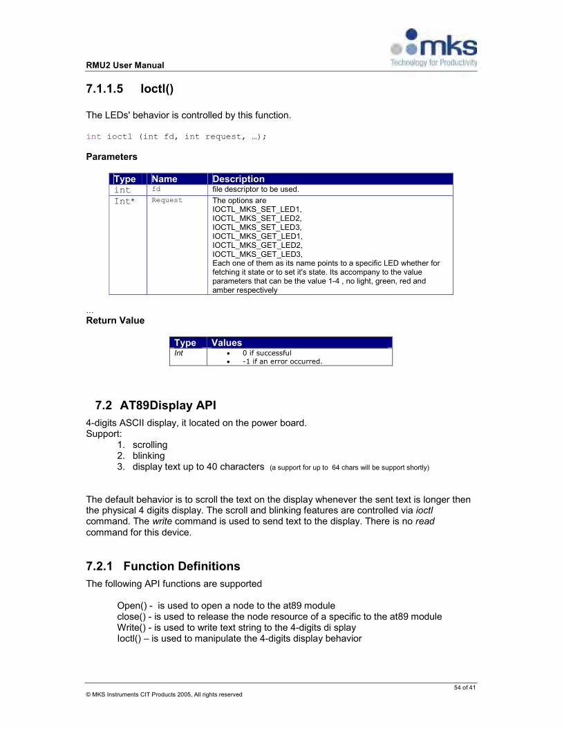
RMU2 User Manual
54 of 41 © MKS Instruments CIT Products 2005, All rights reserved
7.1.1.5 Ioctl()
The LEDs' behavior is controlled by this function. int ioctl (int fd, int request, …);
Parameters
Type Name Description int fd file descriptor to be used.
Int* Request The options are IOCTL_MKS_SET_LED1, IOCTL_MKS_SET_LED2, IOCTL_MKS_SET_LED3, IOCTL_MKS_GET_LED1, IOCTL_MKS_GET_LED2, IOCTL_MKS_GET_LED3, Each one of them as its name points to a specific LED whether for fetching it state or to set it's state. Its accompany to the value parameters that can be the value 1-4 , no light, green, red and amber respectively
…
Return Value
Type Values Int • 0 if successful
• -1 if an error occurred.
7.2 AT89Display API
4-digits ASCII display, it located on the power board. Support:
1. scrolling 2. blinking 3. display text up to 40 characters (a support for up to 64 chars will be support shortly)
The default behavior is to scroll the text on the display whenever the sent text is longer then the physical 4 digits display. The scroll and blinking features are controlled via ioctl command. The write command is used to send text to the display. There is no read command for this device.
7.2.1 Function Definitions
The following API functions are supported Open() - is used to open a node to the at89 module
close() - is used to release the node resource of a specific to the at89 module Write() - is used to write text string to the 4-digits di splay
Ioctl() – is used to manipulate the 4-digits display behavior

RMU2 User Manual
55 of 42 © MKS Instruments CIT Products 2005, All rights reserved
7.2.1.1 Open()
Open a connection to the display device.
int open( const char* pathname, int flags);
Parameters
Type Name Description Char Pathname the path name to the DIO device file ( in this case
/dev/at89display ) int flags one of the O_RDONLY, O_WRONLY or O_RDWR
options to open the file. Usually it would be O_RDWR , for reading and writing.
Return Value
Type Values Int The file descriptor if successful
-1 if an error occurred.
Discussion Open a data channel to the display controller.
7.2.1.2 Close()
Close an open connection to the display int close ( int fd);
Parameters
Type Name Description Char fd file descriptor to be closed
Return Value
Type Values Int 0 if successful
-1 if an error occurred.
Discussion Close function for the display.
7.2.1.3 Write()
Writes the text string contained in the buffer to the display ssize_t write ( int fd, const void* buf, size_t len);
Parameters
Type Name Description Char Fd file descriptor to be write to
Void* Buf pointer to buffer in memory that contains the text string to be display
Size_t Len number of bytes to be write

RMU2 User Manual
56 of 43 © MKS Instruments CIT Products 2005, All rights reserved
Return Value
Type Values ssize_t • number of actual bytes written.
• -1 if an error occurred.
7.2.1.4 Ioctl()
Control the behavior of the display’s scroll and blink. int ioctl (int fd, int request, …);
Parameters
Type Name Description int fd file descriptor to be used.
Int* Request there are two control options fro the scroll, the scroll speed, and scroll step. The scroll speed is the time gap between each display scroll refresh (not internal display screen refresh). Scroll step is the number on character to shift per each refresh. Blink is the effect in which appearance and disappearance of the entire content on the display is toggled. Value 0 stop the blink any other positive value is the number of 10ms delay between each toggle
The associated parameters, goes with the ioctl command. Each command defines its own associated parameters type and behavior.
List of Set/Get command pairs:
Command Description MKS_IOCTL_GET_SCROLL_SPEED MKS_IOCTL_SET_SCROLL_SPEED
Set/get the display scroll refresh in units of milliseconds, zero value disables the scrolling.
Associated parameter:
Type: unsigned long
Value: 0 – disable scrolling
any other value is legal.
MKS_IOCTL_GET_SCROLL_STEP MKS_IOCTL_SET_SCROLL_STEP
Set/get the display scroll step size in characters, zero value disables the scrolling.
Associated parameter:
Type: unsigned char
Value: 0 – disable scrolling
any other value is legal
MKS_IOCTL_GET_BLINK MKS_IOCTL_SET_BLINK
Set/get the display blink delay , zero value disables the blinking.

RMU2 User Manual
57 of 44 © MKS Instruments CIT Products 2005, All rights reserved
Associated parameter:
Type: unsigned char
Value: 0 – disable blinking
any other value is legal
Return Value
Type Values Int • 0 if successful
• -1 if an error occurred.
7.3 AT89Buttons API
There are two push buttons on the power board. There status can be fetched by reading the /dev/at89buttons device. The read operation could be blocked or non-blocked. Both techniques trigger a communication message to the AT89 in order to retrieve the current buttons states. The caller will be informed whether the buttons were not pushed, were pushed or were pushed and released. NOTE: An interrupt driven mechanism is in development; it will be combined with the operation of the block mode. NOTE: Currently, the blocking mode is implemented without the support of an interrupt, but based on the driver being updated regarding the buttons states each time the driver communicate with the AT89. It’s not recommended to use the blocking mode without the support of a hardware interrupt. Support for hardware interrupt is in development.
7.3.1 Function Definitions
The following API functions are supported Open() - is used to open a node to the AT89 buttons module
close() – is used to release the node resource of AT89 buttons module Read() is used to read the input channels of the card
Ioctl() - used for a blocking / nonblocking configuration
7.3.1.1 Open()
Open a connection to the AT89 buttons module.
int open( const char* pathname, int flags);
Parameters
Type Name Description Char Pathname the path name to the DIO device file ( e.g.
/dev/at89buttons)

RMU2 User Manual
58 of 45 © MKS Instruments CIT Products 2005, All rights reserved
int flags one of the O_RDONLY, O_WRONLY or O_RDWR options to open the file. Usually it would be O_RDWR , for reading and writing.
Return Value
Type Values Int The file descriptor if successful
-1 if an error occurred.
Discussion The open function for the AT89buttons opens a data channel.
7.3.1.2 Close()
Close an open connection to the AT89buttons int close ( int fd);
Parameters
Type Name Description Char fd file descriptor to be closed
Return Value
Type Values Int 0 if successful
-1 if an error occurred.
Discussion Close function closes the channel to the AT89buttons.
7.3.1.3 Read()
Reads the buttons status register, the size to be reading should be 1 byte. ssize_t read ( int fd, const void* buf, size_t len);
Parameters
Type Name Description Char Fd file descriptor to be write to
Void* Buf pointer to buffer in memory that will contain the data from the buttons register
Size_t Len number of bytes to be
Discussion For now the only working mechanism is polling, therefore the read will be a non-block by default. Each time the key status is read, the driver clears the status register for the next

RMU2 User Manual
59 of 46 © MKS Instruments CIT Products 2005, All rights reserved
read. The read register (1byte). Hold the information for both buttons. Each button state is represented by 2 bits. Bits 0-1 are the first button state, the following bits 2-3 are the second button state.
Button's state values
State Value not pressed 0
Pressed 1
Released 2
Pressed & Released
3
7.3.1.4 Ioctl()
Control the behavior of the buttons blocking / non blocking working mode. At this point only a non block mode is enabled. When the blocking working mode will be handy this characteristic will be controlled be the ioctl's IOCTL_MKS_SET_NONBLOCK code. int ioctl (int fd, int request, …);
Parameters
Type Name Description int fd file descriptor to be used.
Int* Request there are two control options fro the scroll, the scroll speed, and scroll step. The scroll speed is the time gap between each display scroll refresh (not internal display screen refresh). Scroll step is the number on character to shift per each refresh.
Return Value
Type Values ssize_t • number of actual bytes written.
• 1 if an error occurred.
List of Set/Get command pairs:
Type Values IOCTL_MKS_SET_NONBLOCK 0 – blocking mode
1- non blocking mode
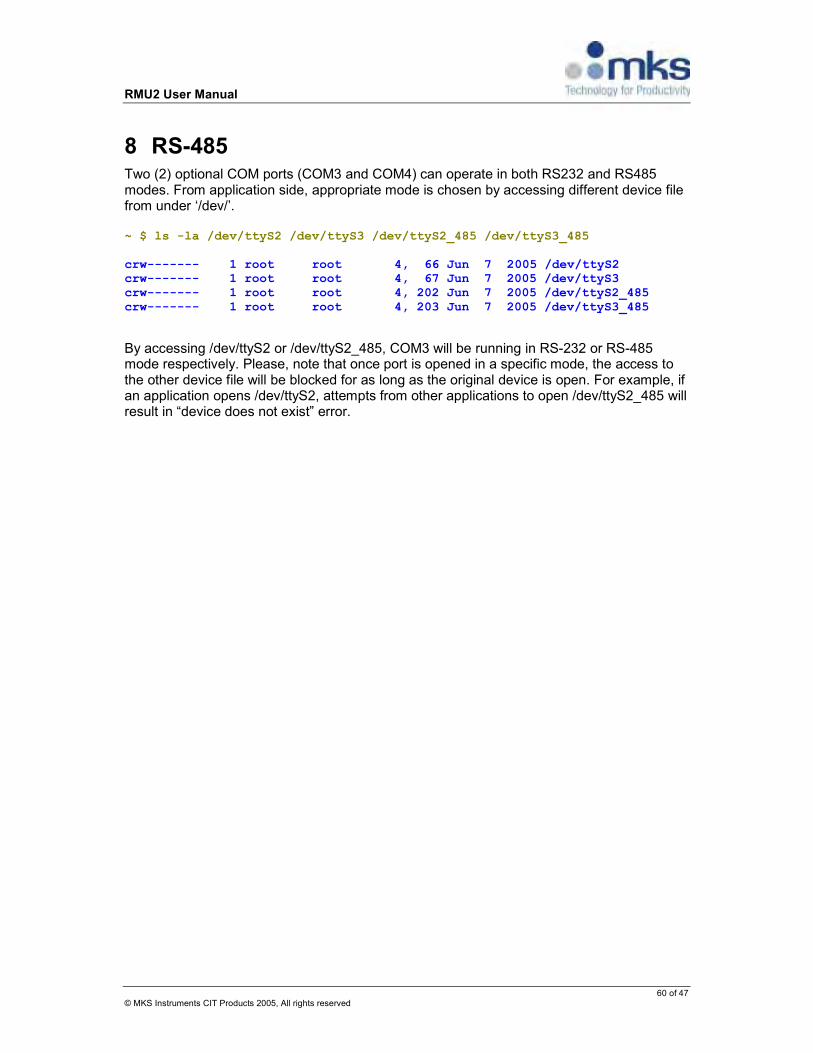
RMU2 User Manual
60 of 47 © MKS Instruments CIT Products 2005, All rights reserved
8 RS-485 Two (2) optional COM ports (COM3 and COM4) can operate in both RS232 and RS485 modes. From application side, appropriate mode is chosen by accessing different device file from under ‘/dev/’. ~ $ ls -la /dev/ttyS2 /dev/ttyS3 /dev/ttyS2_485 /dev/ttyS3_485 crw------- 1 root root 4, 66 Jun 7 2005 /dev/ttyS2 crw------- 1 root root 4, 67 Jun 7 2005 /dev/ttyS3 crw------- 1 root root 4, 202 Jun 7 2005 /dev/ttyS2_485 crw------- 1 root root 4, 203 Jun 7 2005 /dev/ttyS3_485
By accessing /dev/ttyS2 or /dev/ttyS2_485, COM3 will be running in RS-232 or RS-485 mode respectively. Please, note that once port is opened in a specific mode, the access to the other device file will be blocked for as long as the original device is open. For example, if an application opens /dev/ttyS2, attempts from other applications to open /dev/ttyS2_485 will result in “device does not exist” error.

RMU2 User Manual
61 of 48 © MKS Instruments CIT Products 2005, All rights reserved
Appendix A: POSIX Functions Description
For more details, please refer to Linux manual pages
1. Function “open”
NAME
open, creat - open and possibly create a file or device
SYNOPSIS
#include <sys/types.h> #include <sys/stat.h> #include <fcntl.h>
int open(const char *pathname, int flags); int open(const char *pathname, int flags, mode_t mode); int creat(const char *pathname, mode_t mode);
DESCRIPTION Given a pathname for a file, open() returns a file descriptor, a small, non-negative integer for use in subsequent system calls (read(2), write(2), lseek(2), fcntl(2), etc.). The file descriptor returned by a successful call will be the lowest-numbered file
descriptor not currently open for the process.
The new file descriptor is set to remain open across an execve(2) (i.e., the FD_CLOEXEC file descriptor flag described in
fcntl(2) is initially disabled). The file offset is set to the beginning of the file (see lseek(2)).
A call to open() creates a new open file description, an entry in the system-wide table of open files. This entry records the file offset and the file status flags (modifiable via the fcntl() F_SETFL operation). A file descriptor is a reference to one of these
entries; this reference is unaffected if pathname is subsequently removed or modified to refer to a different file. The new open
file description is initially not shared with any other process, but sharing may arise via fork(2).
The parameter flags must include one of the following access modes: O_RDONLY, O_WRONLY, or O_RDWR. These request
opening the file read-only, write-only, or read/write, respectively.
In addition, zero or more file creation flags and file status flags can be bitwise-or'd in flags. The file creation flags are O_CREAT, O_EXCL, O_NOCTTY, and O_TRUNC. The file status flags are all of the remaining flags listed below. The distinction between these two groups of flags is that the file status flags can be retrieved and (in some cases) modified using
fcntl(2). The full list of file creation flags and file status flags is as follows:
O_APPEND
The file is opened in append mode. Before each write(), the file offset is positioned at the end of the file, as if with lseek(). O_APPEND may lead to corrupted files on NFS file systems if more than one process appends data to a file at once. This is because NFS does not support appending to a file, so the client kernel has to simulate it, which can't
be done without a race condition.
O_ASYNC Enable signal-driven I/O: generate a signal (SIGIO by default, but this can be changed via fcntl(2)) when input or
output becomes possible on this file descriptor. This feature is only available for terminals, pseudo-terminals,
sockets, and (since Linux 2.6) pipes and FIFOs. See fcntl(2) for further details.
O_CREAT If the file does not exist it will be created. The owner (user ID) of the file is set to the effective user ID of the
process. The group ownership (group ID) is set either to the effective group ID of the process or to the group ID of
the parent directory (depending on filesystem type and mount options, and the mode of the parent directory, see, e.g., the mount options bsdgroups and sysvgroups of the ext2 filesystem, as described in mount(8)).
O_DIRECT
Try to minimize cache effects of the I/O to and from this file. In general this will degrade performance, but it is
useful in special situations, such as when applications do their own caching. File I/O is done directly to/from user
space buffers. The I/O is synchronous, i.e., at the completion of a read(2) or write(2), data is guaranteed to have been transferred. Under Linux 2.4 transfer sizes, and the alignment of user buffer and file offset must all be
multiples of the logical block size of the file system. Under Linux 2.6 alignment to 512-byte boundaries suffices.
A semantically similar (but deprecated) interface for block devices is described in raw(8).
O_DIRECTORY
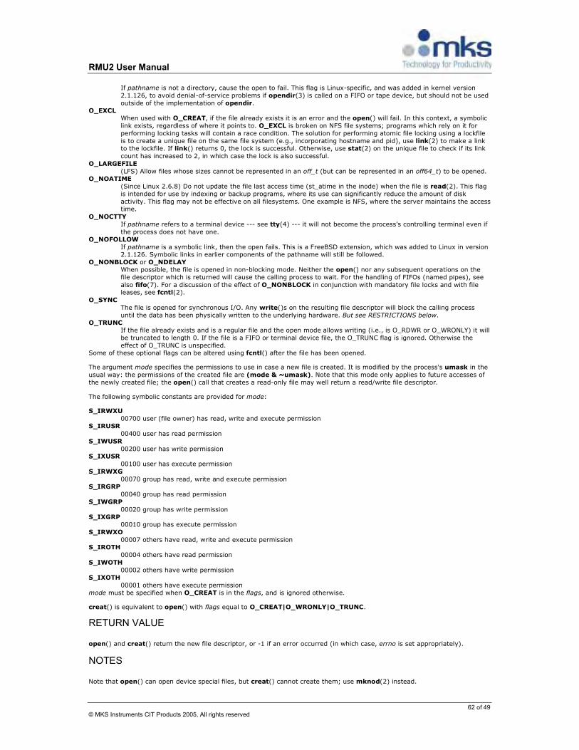
RMU2 User Manual
62 of 49 © MKS Instruments CIT Products 2005, All rights reserved
If pathname is not a directory, cause the open to fail. This flag is Linux-specific, and was added in kernel version
2.1.126, to avoid denial-of-service problems if opendir(3) is called on a FIFO or tape device, but should not be used
outside of the implementation of opendir. O_EXCL
When used with O_CREAT, if the file already exists it is an error and the open() will fail. In this context, a symbolic
link exists, regardless of where it points to. O_EXCL is broken on NFS file systems; programs which rely on it for
performing locking tasks will contain a race condition. The solution for performing atomic file locking using a lockfile
is to create a unique file on the same file system (e.g., incorporating hostname and pid), use link(2) to make a link to the lockfile. If link() returns 0, the lock is successful. Otherwise, use stat(2) on the unique file to check if its link
count has increased to 2, in which case the lock is also successful.
O_LARGEFILE
(LFS) Allow files whose sizes cannot be represented in an off_t (but can be represented in an off64_t) to be opened. O_NOATIME
(Since Linux 2.6.8) Do not update the file last access time (st_atime in the inode) when the file is read(2). This flag
is intended for use by indexing or backup programs, where its use can significantly reduce the amount of disk
activity. This flag may not be effective on all filesystems. One example is NFS, where the server maintains the access time.
O_NOCTTY
If pathname refers to a terminal device --- see tty(4) --- it will not become the process's controlling terminal even if
the process does not have one. O_NOFOLLOW
If pathname is a symbolic link, then the open fails. This is a FreeBSD extension, which was added to Linux in version 2.1.126. Symbolic links in earlier components of the pathname will still be followed.
O_NONBLOCK or O_NDELAY When possible, the file is opened in non-blocking mode. Neither the open() nor any subsequent operations on the
file descriptor which is returned will cause the calling process to wait. For the handling of FIFOs (named pipes), see
also fifo(7). For a discussion of the effect of O_NONBLOCK in conjunction with mandatory file locks and with file leases, see fcntl(2).
O_SYNC
The file is opened for synchronous I/O. Any write()s on the resulting file descriptor will block the calling process
until the data has been physically written to the underlying hardware. But see RESTRICTIONS below. O_TRUNC
If the file already exists and is a regular file and the open mode allows writing (i.e., is O_RDWR or O_WRONLY) it will
be truncated to length 0. If the file is a FIFO or terminal device file, the O_TRUNC flag is ignored. Otherwise the
effect of O_TRUNC is unspecified. Some of these optional flags can be altered using fcntl() after the file has been opened.
The argument mode specifies the permissions to use in case a new file is created. It is modified by the process's umask in the
usual way: the permissions of the created file are (mode & ~umask). Note that this mode only applies to future accesses of
the newly created file; the open() call that creates a read-only file may well return a read/write file descriptor.
The following symbolic constants are provided for mode:
S_IRWXU
00700 user (file owner) has read, write and execute permission S_IRUSR
00400 user has read permission
S_IWUSR
00200 user has write permission S_IXUSR
00100 user has execute permission
S_IRWXG
00070 group has read, write and execute permission S_IRGRP
00040 group has read permission
S_IWGRP
00020 group has write permission S_IXGRP
00010 group has execute permission
S_IRWXO
00007 others have read, write and execute permission S_IROTH
00004 others have read permission
S_IWOTH
00002 others have write permission S_IXOTH
00001 others have execute permission
mode must be specified when O_CREAT is in the flags, and is ignored otherwise.
creat() is equivalent to open() with flags equal to O_CREAT|O_WRONLY|O_TRUNC.
RETURN VALUE open() and creat() return the new file descriptor, or -1 if an error occurred (in which case, errno is set appropriately).
NOTES Note that open() can open device special files, but creat() cannot create them; use mknod(2) instead.

RMU2 User Manual
63 of 50 © MKS Instruments CIT Products 2005, All rights reserved
On NFS file systems with UID mapping enabled, open() may return a file descriptor but e.g. read(2) requests are denied with
EACCES. This is because the client performs open() by checking the permissions, but UID mapping is performed by the server
upon read and write requests.
If the file is newly created, its st_atime, st_ctime, st_mtime fields (respectively, time of last access, time of last status change,
and time of last modification; see stat(2)) are set to the current time, and so are the st_ctime and st_mtime fields of the parent directory. Otherwise, if the file is modified because of the O_TRUNC flag, its st_ctime and st_mtime fields are set to the
current time.
ERRORS EACCES
The requested access to the file is not allowed, or search permission is denied for one of the directories in the path
prefix of pathname, or the file did not exist yet and write access to the parent directory is not allowed. (See also
path_resolution(2).) EEXIST
pathname already exists and O_CREAT and O_EXCL were used.
EFAULT
pathname points outside your accessible address space. EISDIR
pathname refers to a directory and the access requested involved writing (that is, O_WRONLY or O_RDWR is set).
ELOOP
Too many symbolic links were encountered in resolving pathname, or O_NOFOLLOW was specified but pathname was a symbolic link.
EMFILE
The process already has the maximum number of files open.
ENAMETOOLONG pathname was too long.
ENFILE
The system limit on the total number of open files has been reached.
ENODEV pathname refers to a device special file and no corresponding device exists. (This is a Linux kernel bug; in this
situation ENXIO must be returned.)
ENOENT O_CREAT is not set and the named file does not exist. Or, a directory component in pathname does not exist or is a dangling symbolic link.
ENOMEM
Insufficient kernel memory was available.
ENOSPC pathname was to be created but the device containing pathname has no room for the new file.
ENOTDIR
A component used as a directory in pathname is not, in fact, a directory, or O_DIRECTORY was specified and
pathname was not a directory. ENXIO
O_NONBLOCK | O_WRONLY is set, the named file is a FIFO and no process has the file open for reading. Or, the file
is a device special file and no corresponding device exists.
EOVERFLOW pathname refers to a regular file, too large to be opened; see O_LARGEFILE above.
EPERM
The O_NOATIME flag was specified, but the effective user ID of the caller did not match the owner of the file and
the caller was not privileged (CAP_FOWNER). EROFS
pathname refers to a file on a read-only filesystem and write access was requested. ETXTBSY
pathname refers to an executable image which is currently being executed and write access was requested. EWOULDBLOCK
The O_NONBLOCK flag was specified, and an incompatible lease was held on the file (see fcntl(2)).
NOTE Under Linux, the O_NONBLOCK flag indicates that one wants to open but does not necessarily have the intention to read or
write. This is typically used to open devices in order to get a file descriptor for use with ioctl(2).
CONFORMING TO SVr4, 4.3BSD, POSIX.1-2001. The O_NOATIME, O_NOFOLLOW, and O_DIRECTORY flags are Linux-specific. One may have
to define the _GNU_SOURCE macro to get their definitions.
The (undefined) effect of O_RDONLY | O_TRUNC varies among implementations. On many systems the file is actually
truncated.
The O_DIRECT flag was introduced in SGI IRIX, where it has alignment restrictions similar to those of Linux 2.4. IRIX has also a fcntl(2) call to query appropriate alignments, and sizes. FreeBSD 4.x introduced a flag of same name, but without alignment
restrictions. Support was added under Linux in kernel version 2.4.10. Older Linux kernels simply ignore this flag. One may
have to define the _GNU_SOURCE macro to get its definition.
BUGS

RMU2 User Manual
64 of 51 © MKS Instruments CIT Products 2005, All rights reserved
"The thing that has always disturbed me about O_DIRECT is that the whole interface is just stupid, and was probably designed
by a deranged monkey on some serious mind-controlling substances." --- Linus
Currently, it is not possible to enable signal-driven I/O by specifying O_ASYNC when calling open(); use fcntl(2) to enable this flag.
RESTRICTIONS There are many infelicities in the protocol underlying NFS, affecting amongst others O_SYNC and O_NDELAY. POSIX provides for three different variants of synchronised I/O, corresponding to the flags O_SYNC, O_DSYNC and
O_RSYNC. Currently (2.1.130) these are all synonymous under Linux.
SEE ALSO close(2), dup(2), fcntl(2), link(2), lseek(2), mknod(2), mount(2), mmap(2), openat(2), path_resolution(2), read(2),
socket(2), stat(2), umask(2), unlink(2), write(2), fopen(3), fifo(7), feature_test_macros(7)
RMU2 User Manual
65 of 52 © MKS Instruments CIT Products 2005, All rights reserved
2. Function “close”
NAME
close - close a file descriptor
SYNOPSIS
#include <unistd.h>
int close(int fd);
DESCRIPTION
close() closes a file descriptor, so that it no longer refers to any file and may be reused. Any record locks (see fcntl(2)) held
on the file it was associated with, and owned by the process, are removed (regardless of the file descriptor that was used to obtain the lock).
If fd is the last copy of a particular file descriptor the resources associated with it are freed; if the descriptor was the last
reference to a file which has been removed using unlink(2) the file is deleted.
RETURN VALUE
close() returns zero on success. On error, -1 is returned, and errno is set appropriately.
ERRORS
EBADF fd isn't a valid open file descriptor.
EINTR
The close() call was interrupted by a signal.
EIO An I/O error occurred.
CONFORMING TO
SVr4, 4.3BSD, POSIX.1-2001.
NOTES
Not checking the return value of close() is a common but nevertheless serious programming error. It is quite possible that
errors on a previous write(2) operation are first reported at the final close(). Not checking the return value when closing the file may lead to silent loss of data. This can especially be observed with NFS and with disk quota.
A successful close does not guarantee that the data has been successfully saved to disk, as the kernel defers writes. It is not
common for a filesystem to flush the buffers when the stream is closed. If you need to be sure that the data is physically stored use fsync(2). (It will depend on the disk hardware at this point.)
SEE ALSO
fcntl(2), fsync(2), open(2), shutdown(2), unlink(2), fclose(3)

RMU2 User Manual
66 of 53 © MKS Instruments CIT Products 2005, All rights reserved
3. Function “read”
NAME
read - read from a file descriptor
SYNOPSIS
#include <unistd.h>
ssize_t read(int fd, void *buf, size_t count);
DESCRIPTION
read() attempts to read up to count bytes from file descriptor fd into the buffer starting at buf.
If count is zero, read() returns zero and has no other results. If count is greater than SSIZE_MAX, the result is unspecified.
RETURN VALUE
On success, the number of bytes read is returned (zero indicates end of file), and the file position is advanced by this number.
It is not an error if this number is smaller than the number of bytes requested; this may happen for example because fewer
bytes are actually available right now (maybe because we were close to end-of-file, or because we are reading from a pipe, or
from a terminal), or because read() was interrupted by a signal. On error, -1 is returned, and errno is set appropriately. In this case it is left unspecified whether the file position (if any) changes.
ERRORS
EAGAIN Non-blocking I/O has been selected using O_NONBLOCK and no data was immediately available for reading.
EBADF
fd is not a valid file descriptor or is not open for reading. EFAULT
buf is outside your accessible address space.
EINTR
The call was interrupted by a signal before any data was read.
EINVAL fd is attached to an object which is unsuitable for reading; or the file was opened with the O_DIRECT flag, and
either the address specified in buf, the value specified in count, or the current file offset is not suitably aligned.
EIO
I/O error. This will happen for example when the process is in a background process group, tries to read from its controlling tty, and either it is ignoring or blocking SIGTTIN or its process group is orphaned. It may also occur when there is a low-level I/O error while reading from a disk or tape.
EISDIR
fd refers to a directory. Other errors may occur, depending on the object connected to fd. POSIX allows a read() that is interrupted after reading some
data to return -1 (with errno set to EINTR) or to return the number of bytes already read.
CONFORMING TO
SVr4, 4.3BSD, POSIX.1-2001.
RESTRICTIONS
On NFS file systems, reading small amounts of data will only update the time stamp the first time, subsequent calls may not do so. This is caused by client side attribute caching, because most if not all NFS clients leave st_atime (last file access time) updates to the server and client side reads satisfied from the client's cache will not cause st_atime updates on the server as
there are no server side reads. UNIX semantics can be obtained by disabling client side attribute caching, but in most
situations this will substantially increase server load and decrease performance.
Many filesystems and disks were considered to be fast enough that the implementation of O_NONBLOCK was deemed unnecessary. So, O_NONBLOCK may not be available on files and/or disks.
SEE ALSO
close(2), fcntl(2), ioctl(2), lseek(2), open(2), pread(2), readdir(2), readlink(2), readv(2), select(2), write(2), fread(3)

RMU2 User Manual
67 of 54 © MKS Instruments CIT Products 2005, All rights reserved
4. Function “write”
NAME
write - write to a file descriptor
SYNOPSIS
#include <unistd.h>
ssize_t write(int fd, void *buf, size_t count);
DESCRIPTION
write() writes up to count bytes to the file referenced by the file descriptor fd from the buffer starting at buf. POSIX requires
that a read() which can be proved to occur after a write() has returned returns the new data. Note that not all file systems are POSIX conforming.
RETURN VALUE
On success, the number of bytes written are returned (zero indicates nothing was written). On error, -1 is returned, and errno is set appropriately. If count is zero and the file descriptor refers to a regular file, 0 may be returned, or an error could be
detected. For a special file, the results are not portable.
ERRORS
EAGAIN
Non-blocking I/O has been selected using O_NONBLOCK and the write would block.
EBADF
fd is not a valid file descriptor or is not open for writing. EFAULT
buf is outside your accessible address space.
EFBIG
An attempt was made to write a file that exceeds the implementation-defined maximum file size or the process' file size limit, or to write at a position past the maximum allowed offset.
EINTR
The call was interrupted by a signal before any data was written.
EINVAL fd is attached to an object which is unsuitable for writing; or the file was opened with the O_DIRECT flag, and either
the address specified in buf, the value specified in count, or the current file offset is not suitably aligned.
EIO
A low-level I/O error occurred while modifying the inode. ENOSPC
The device containing the file referred to by fd has no room for the data. EPIPE
fd is connected to a pipe or socket whose reading end is closed. When this happens the writing process will also receive a SIGPIPE signal. (Thus, the write return value is seen only if the program catches, blocks or ignores this
signal.)
Other errors may occur, depending on the object connected to fd.
CONFORMING TO
SVr4, 4.3BSD, POSIX.1-2001.
Under SVr4 a write may be interrupted and return EINTR at any point, not just before any data is written.
NOTES
A successful return from write() does not make any guarantee that data has been committed to disk. In fact, on some buggy implementations, it does not even guarantee that space has successfully been reserved for the data. The only way to be sure is
to call fsync(2) after you are done writing all your data.
SEE ALSO
close(2), fcntl(2), fsync(2), ioctl(2), lseek(2), open(2), pwrite(2), read(2), select(2), writev(3), fwrite(3)
RMU2 User Manual
68 of 55 © MKS Instruments CIT Products 2005, All rights reserved
5. Function “ioctl”
NAME
ioctl - control device
SYNOPSIS
#include <sys/ioctl.h>
ssize_t ioctl(int d, int request, ...);
DESCRIPTION
The ioctl() function manipulates the underlying device parameters of special files. In particular, many operating characteristics
of character special files (e.g. terminals) may be controlled with ioctl() requests. The argument d must be an open file descriptor.
The second argument is a device-dependent request code. The third argument is an untyped pointer to memory. It's
traditionally char *argp (from the days before void * was valid C), and will be so named for this discussion.
An ioctl() request has encoded in it whether the argument is an in parameter or out parameter, and the size of the argument
argp in bytes. Macros and defines used in specifying an ioctl() request are located in the file <sys/ioctl.h>.
RETURN VALUE
Usually, on success zero is returned. A few ioctl() requests use the return value as an output parameter and return a
nonnegative value on success. On error, -1 is returned, and errno is set appropriately.
ERRORS
EBADF d is not a valid descriptor.
EFAULT argp references an inaccessible memory area.
EINVAL
Request or argp is not valid.
ENOTTY d is not associated with a character special device.
ENOTTY
The specified request does not apply to the kind of object that the descriptor d references.
NOTE
In order to use this call, one needs an open file descriptor. Often the open(2) call has unwanted side effects, that can be
avoided under Linux by giving it the O_NONBLOCK flag.
CONFORMING TO
No single standard. Arguments, returns, and semantics of ioctl(2) vary according to the device driver in question (the call is
used as a catch-all for operations that don't cleanly fit the Unix stream I/O model). See ioctl_list(2) for a list of many of the known ioctl() calls. The ioctl() function call appeared in Version 7 AT&T Unix.
SEE ALSO
execve(2), fcntl(2), ioctl_list(2), open(2), mt(4), sd(4), tty(4)

RMU2 User Manual
69 of 56 © MKS Instruments CIT Products 2005, All rights reserved
Appendix B: How to Cross-Compile tcpdump Note: you do not need super-user privileges in order to be able to build the utility. Download and unpack libcap and tcpdump (in this example, to /home/rmu/tcpdump/): cd /home/rmu; mkdir tcpdump; cd tcpdump wget http://www.tcpdump.org/release/tcpdump-3.9.5.tar.gz wget http://www.tcpdump.org/release/libpcap-0.9.5.tar.gz
The environment variables need to be set for the console where we are going to build both libpcap and tcpdump: export PATH=$PATH:/opt/eldk-3.1.1/usr/bin:/opt/eldk-3.1.1/bin export CROSS_COMPILE=ppc_82xx-
export CC=ppc_82xx-gcc export ARCH=ppc export ac_cv_func_setvbuf_reversed=no export ac_cv_linux_vers=2
libcap: cd /home/rmu/tcpdump tar zxf libpcap-0.9.5.tar.gz
cd libpcap-0.9.5 ./configure --target=powerpc-linux --host=i686-pc-linux-gnu --build=powerpc-linux --prefix=`pwd`/_install --exec-prefix=`pwd`/_install-bin --with-pcap=linux make; make install
tcpdump: cd /home/rmu/tcpdump tar zxf tcpdump-3.9.5.tar.gz
cd tcpdump-3.9.5 ./configure --target=powerpc-linux --host=i686-pc-linux-gnu --build=powerpc-linux --prefix=`pwd`/_install --exec-prefix=`pwd`/_install-bin LDFLAGS=-L/home/rmu/tcpdump/libpcap-0.9.5-ppc/_install-bin/lib CFLAGS=-I/home/rmu/tcpdump/libpcap-0.9.5-ppc/_install/include --without-crypto make; make install
As a result of successful configuration and build you get ready-to-run binary: ~ $ ls -al /home/rmu/tcpdump/tcpdump-3.9.5/_install-bin/sbin -rwxr-xr-x 1 mm users 730077 2007-01-15 12:31 tcpdump
To reduce some space, the binary could be stripped: ~ $ ppc_82xx-strip /home/rmu/tcpdump/tcpdump-3.9.5/_install-bin/sbin/tcpdump ~ $ ls -al /home/rmu/tcpdump/tcpdump-3.9.5/_install-bin/sbin -rwxr-xr-x 1 mm users 655036 2007-01-15 12:31 tcpdump

RMU2 User Manual
70 of 57 © MKS Instruments CIT Products 2005, All rights reserved
Appendix C: How to Cross-Compile Boa Web Server Note: you do not need super-user privileges in order to be able to build the utility. Download and unpack sources (in this example, to /home/rmu/boa/): cd /home/rmu; mkdir boa; cd boa wget http://www.boa.org/boa-0.94.14rc21.tar.gz
The environment variables need to be set for the console: export PATH=$PATH:/opt/eldk-3.1.1/usr/bin:/opt/eldk-3.1.1/bin export CROSS_COMPILE=ppc_82xx-
export CC=ppc_82xx-gcc export ARCH=ppc export ac_cv_func_setvbuf_reversed=no export ac_cv_linux_vers=2
boa: cd /home/rmu/boa tar zxf boa-0.94.14rc21.tar.gz
cd boa-0.94.14rc21 ./configure --target=powerpc-linux --host=i686-pc-linux-gnu --build=powerpc-linux --prefix=`pwd`/_install --exec-prefix=`pwd`/_install-bin make
As a result of successful configuration and build you get ready-to-run binary: ~ $ ls -al /home/rmu/boa/boa-0.94.14rc21/src/boa -rwxr-xr-x 1 mm users 656910 2007-01-15 17:11 boa
To reduce some space, the binary could be stripped: ~ $ ppc_82xx-strip /home/rmu/boa/boa-0.94.14rc21/src/boa ~ $ ls -al /home/rmu/boa/boa-0.94.14rc21/src/boa -rwxr-xr-x 1 mm users 77800 2007-01-15 17:12 boa
Please, note significant reduction of binary size.

RMU2 User Manual
71 of 58 © MKS Instruments CIT Products 2005, All rights reserved
Specifications Physical Specifications
Criteria Specifications
Dimensions 4” H x 4” W x 1.5”D plus 0.7” per I/O slot I/O Connector 37-pin male D-sub Ethernet Connector 100 BaseT, RJ45 with EMI filter,LED indicators
RS-232 Connector DB9 male connector
Weight 600g (1.32 lb)
Environmental Specifications
Criteria Specifications
Operating Temperature 0 to +55°C Storage -40 to +85 °C Humidity 5 to 95% non-condensing
Functional Specifications
Criteria Specifications
PowerPC 400 MHz, 760 MIPS with support of floating point instructions
On board Flash 16 MB
SDRAM 128 MB
CompactFlash Port Type II, currently tested up to 4GB
RS232 4 RS232 interface. (1 port used for diagnostics port, software selectable 485 on 2 of ports)
BUS Interface 2 isolated Ethernet ports – Modbus/TCP or Ethernet/IP
USB USB 1.1 port Front Panel Indicators Network Status, Module Status, LINK, 100MB Rotary Switches IP address, operating mode
Power Specifications
Criteria Specifications
Input Powered from I/O connector +24VDC@120 mA min
Isolation DC/DC Isolation, 2.5KVrms Over Current Protection Each Channel Total
1.5A 3.0A
Input/Output Specifications per Card
Criteria Specifications
DIDO Card
Number of Digital I/O 24 points (input or output)
Response Time 50µsec Digital Input Sink Current sinking Logic Low Voltage Logic High Voltage Source Current sourcing Input Low Voltage Input High Voltage
1.5 mA min, Max -2.18 mA at Vin=0V Min 8.1V to Max 30V Min 0V to Max 7V 1.5 mA min, Max 2.33 mA at Vin=24V Min 0V to Max 6V Min 6.5V to Max 30V
Digital Output

RMU2 User Manual
72 of 58 © MKS Instruments CIT Products 2005, All rights reserved
Sink Current sinking Output OFF Voltage Output ON Voltage Source Current sourcing Current max Output ON Voltage Output OFF Voltage
200 mA max / channel Min 23.8V @ 580uA @ RL=240Ω Min 23.8V @ 1mA @ RL=120Ω Max 240mV @ 200mA @ RL=120Ω Max 133mV @ 100mA @ RL=240Ω 200 mA max / channel 750 mA per 6 DO Min 23.3V @ 100mA @ RL=240Ω Min 23.1V @ 200mA @ RL=120Ω Max 0V @ 0uA @ RL=120Ω Max 0V @ 0mA @ RL=240Ω
AIAO Card Analog Accuracy 0.1% Full scale (-10V to 10V) Analog Response Time 200 µsec Analog Input 16 single-ended points or 8 differential points (s/w
selectable) 14 bit 1Khz RC filter
Analog Output 8 single-ended points 12 bit Range (–10 to +10V) 5mA / channel into a 2 KΩ load
COMBO Card
Number of Digital I/O 16 points (input or output)
Response Time 50 µsec
Digital Input Current sinking Current sourcing
1.5 mA min, 1.5 mA min,
Digital Output Current sinking Current sourcing Current max
200 mA max / channel 200 mA max / channel 750 mA per 6 DO
Analog Accuracy 0.1% Full scale (-10V to 10V)
Analog Response Time 200 µsec
Analog Input 8 single-ended points or 4 differential points (s/w selectable) 14 bit 1khz RC filter
Analog Output 2 differential points 12 bit Range (–10 to +10V) 5mA / channel into a 2 KΩ load

RMU2 User Manual
73 of 60 © MKS Instruments CIT Products 2005, All rights reserved
Model Code Description
The Model code of RMU defines the features of the Unit for Hardware, software and other options:
BASE OPTIONS
SLOT 1
SLOT 2
SLOT 3
SLOT 4
Format: RMU2 - C - DIDO - DIDO - DIDO - DIDO D AIAO AIAO AIAO AIAO CF AI AI AI AI AH AH AH AH AC AC AC AC COMB COMB COMB COMB
Options -E With CAN and (2) additional RS232/485 ports
-D With Display and Function Keys -CF CompactFlash, range 64MB to 4GB
Slot Designations -DIDO 24 Channel Digital I/O Card -AIAO 16 Channel Analog In, 8 Channel Analog Out -AI 16 Analog Inputs (Voltage Type Inputs) -AH 16 Analog Inputs (High impedance, 1Mohm) -AC 8 Analog Inputs (Current Type Inputs) -COMB Combination: 16DIDO, 4AI-DIF, 2AO-DIF

RMU2 User Manual
74 of 61 © MKS Instruments CIT Products 2005, All rights reserved
WARRANTY
MKS Instruments, Inc. (MKS) warrants that for one year from the date of shipment the equipment described above (the “equipment”) manufactured by MKS shall be free from defects in materials and workmanship and will correctly perform all date-related operations, including without limitation accepting data entry, sequencing, sorting, comparing, and reporting, regardless of the date the operation is performed or the date involved in the operation, provided that, if the equipment exchanges data or is otherwise used with equipment, software, or other products of others, such products of others themselves correctly perform all date-related operations and store and transmit dates and date-related data in a format compatible with MKS equipment. THIS WARRANTY IS MKS’ SOLE WARRANTY CONCERNING DATE-RELATED OPERATIONS.
For the period commencing with the date of shipment of this equipment and ending one year later, MKS will, at its option, either repair or replace any part which is defective in materials or workmanship or with respect to the date-related operations warranty without charge to the purchaser. The foregoing shall constitute the exclusive and sole remedy of the purchaser for any breach by MKS of this warranty.
The purchaser, before returning any equipment covered by this warranty, which is asserted to be defective by the purchaser, shall make specific written arrangements with respect to the responsibility for shipping the equipment and handling any other incidental charges with the MKS sales representative or distributor from which the equipment was purchased or, in the case of a direct purchase from MKS, with the MKS-CIT home office in San Jose, CA
This warranty does not apply to any equipment, which has not been installed and used in accordance with the specifications recommended by MKS for the proper and normal use of the equipment. MKS shall not be liable under any circumstances for indirect, special, consequential, or incidental damages in connection with, or arising out of, the sale, performance, or use of the equipment covered by this warranty.
THIS WARRANTY IS IN LIEU OF ALL OTHER RELEVANT WARRANTIES, EXPRESSED OR IMPLIED, INCLUDING THE IMPLIED WARRANTY OF MERCHANTABILITY AND THE IMPLIED WARRANTY OF FITNESS FOR A PARTICULAR PURPOSE, AND ANY WARRANTY AGAINST INFRINGEMENT OF ANY PATENT.