risk net ver 3_1_1/risk-net 3.1.1 pro user gu… · namely for each exposure pathway activated by...
TRANSCRIPT

RECONnet
Italian Network on the Management and
Remediation of Contaminated Sites
USER GUIDE
Version 3.1.1
September 2019
RISK-NET

Risk-net v.3.1.1 – User Guide
Risk-net
2
RISK-NET
TOOL FOR THE RISK ASSESSMENT OF CONTAMINATED SITES
The Risk-net software was designed to perform the calculations required for the Risk-
Based Corrective Action (RBCA) planning process, as defined in the Italian national
guidelines for risk assessment that are based on the ASTM E-2081-00 Standard Guide
for Risk-Based Corrective Action and ASTM E-1739-95 Standard Guide for Risk-Based
Corrective Action Applied at Petroleum Release Sites.
Author of the document Iason Verginelli, University of Rome “Tor Vergata” Authors of the software Iason Verginelli, University of Rome “Tor Vergata” Alessandro Girelli, I.A. Industria Ambiente S.r.l. Development of the software Iason Verginelli, University of Rome “Tor Vergata” Alessandro Girelli, I.A. Industria Ambiente S.r.l. Carlo Cassinari, Techmakers srl Optimization and validation of the software
Renato Baciocchi, University of Rome “Tor Vergata” Simona Berardi, INAIL Andrea Forni, Ordine degli Ingegneri della Provincia di Bologna Igor Villani, ARPAE Emilia Romagna
Risk-net can be downloaded for free from the website of the Reconnet network at www.reconnet.net Ref: Verginelli I. (2019). Risk-net User Guide. Version 3.1.1. Rome, Italy, Reconnet.

Risk-net v.3.1.1 – User Guide
Risk-net
3
No part of this product may be reproduced without the prior written permission of the authors. The software and the software manual are distributed ‘as is’. No party makes any representation or warranty regarding the accuracy, correctness, or completeness of the information contained in the software and in the manual, and no such party shall be liable for any direct, indirect, consequential, incidental or other damages resulting from the use of this product.

Risk-net v.3.1.1 – User Guide
Risk-net
4
INDEX
Risk-net ............................................................................................................................................ 2
List of Figures .................................................................................................................................. 6
List of Tables ................................................................................................................................... 7
Description of the software .............................................................................................................. 9
Main Screen ................................................................................................................................... 10
Simulation Screen.......................................................................................................................... 13
Simulation Setup............................................................................................................................ 16
Site Description.......................................................................................................................... 16
Conceptual Site Model .............................................................................................................. 17
Receptors .................................................................................................................................. 20
Input ............................................................................................................................................... 22
Contaminants of concern ........................................................................................................... 22
Source Zone Concentration ....................................................................................................... 26
Exposure Factors....................................................................................................................... 28
Site Parameters ......................................................................................................................... 29
Model options ................................................................................................................................ 33
Volatilization ............................................................................................................................... 34
Leaching .................................................................................................................................... 34
Groundwater Dispersion ............................................................................................................ 35
Csat ........................................................................................................................................... 35
Exposure .................................................................................................................................... 36
Limits ......................................................................................................................................... 37
Advanced Site Characterization ................................................................................................ 37
Output ............................................................................................................................................ 39
Risk ............................................................................................................................................ 39
Site-Specific Target Levels (SSTL) ........................................................................................... 40
Cumulative SSTL ....................................................................................................................... 42
SSTLs Hydrocarbons............................................................................................................. 43
Detailed results .............................................................................................................................. 45
Fate & Transport Factors ........................................................................................................... 45

Risk-net v.3.1.1 – User Guide
Risk-net
5
Concentrations at Point of Exposure ......................................................................................... 46
Exposure Rates ......................................................................................................................... 46
Detailed Risk evaluation ............................................................................................................ 47
Detailed SSTL evaluation .......................................................................................................... 48
Off-site transport ........................................................................................................................ 49
Concentrations Details .............................................................................................................. 51
References .................................................................................................................................... 52
Appendices – Equations and Modeling Procedures...................................................................... 54
App. 1a. Risk Calculation (Soil and groundwater) ......................................................................... 55
Individual Risk ........................................................................................................................ 55
Multiple exposure pathways .................................................................................................. 56
Cumulative Risk ..................................................................................................................... 57
Risk for the groundwater resource ........................................................................................ 58
App. 1b. Risk Calculation (Int. Characterization) ........................................................................... 64
App. 1c. Risk Calculation (Agri-Food consumption) ...................................................................... 68
App. 2a. Clean-Up Levels Calculation (SSTL) .............................................................................. 69
Individual Clean-up Levels (SSTL). ....................................................................................... 69
Multiple exposure pathways. ................................................................................................. 70
Cumulative SSTL (Clean-up levels) ...................................................................................... 72
App. 2b. Reference Concentrations .............................................................................................. 81
App. 3a. F&T Factors (Soil and Groundwater) .............................................................................. 84
App. 3b. F&T Factors (Int. Characterization) ............................................................................... 101
App. 4. Intake Rates .................................................................................................................... 107
App. 5. Using Advanced Characterization data ........................................................................... 110
Outdoor air measurements .................................................................................................. 110
Indoor air measurements ..................................................................................................... 111
Soil-gas measurements ....................................................................................................... 112
Flux Chambers measurements ........................................................................................... 113
Leaching Tests .................................................................................................................... 114
App. 6. Detailed concentrations ................................................................................................... 116
App. 7. Age Dependent Adjustment Factor (ADAF) .................................................................... 121
App. 8. Koc and Kd function of pH .............................................................................................. 122

Risk-net v.3.1.1 – User Guide
Risk-net
6
LIST OF FIGURES Figure 1. Main screen of the software Risk-net. ............................................................................ 10
Figure 2. Main Settings. ................................................................................................................. 12
Figure 3. Simulation screen with activated lateral menu. .............................................................. 13
Figure 4. Simulation screen without lateral menu. ........................................................................ 14
Figure 5. Multiple files open. .......................................................................................................... 15
Figure 6. Site description. .............................................................................................................. 16
Figure 7. Conceptual Site Model. .................................................................................................. 17
Figure 8. Integrative characterization. ........................................................................................... 19
Figure 9. Agri-foods characterization............................................................................................. 20
Figure 10. Receptors. .................................................................................................................... 21
Figure 11. Select Contaminants. ................................................................................................... 22
Figure 12. Contaminants properties. ............................................................................................. 23
Figure 13. Database. ..................................................................................................................... 25
Figure 14. Example of new contaminants in the Database. .......................................................... 26
Figure 15. Source Concentration................................................................................................... 27
Figure 16. Exposure Factors. ........................................................................................................ 28
Figure 17. Site Parameters. ........................................................................................................... 30
Figure 18. Site Parameters. ........................................................................................................... 33
Figure 19. Advanced Site Characterization. .................................................................................. 37
Figure 20. Baseline Risks. ............................................................................................................. 39
Figure 21. Site-Specific Target Levels (SSTL). ............................................................................. 41
Figure 22. Cumulative Site-Specific Target Levels (SSTL). .......................................................... 42
Figure 23. SSTL for TPH mixtures. ............................................................................................... 44
Figure 24. Fate & Transport Factors. ............................................................................................ 45
Figure 25. Concentration at the point of exposure. ....................................................................... 46
Figure 26. Exposure Rates. ........................................................................................................... 47
Figure 27. Detailed Risk Evaluation. ............................................................................................. 48
Figure 28. Detailed SSTL Evaluation. ........................................................................................... 49
Figure 29. Off-site transport (groundwater). .................................................................................. 50
Figure 30. Off-site transport (atmosphere). ................................................................................... 50
Figure 31. Concentrations Details. ................................................................................................ 51
Figure 32. Risk – Surface soil. Multiple exposures. ...................................................................... 56
Figure 33. Risk – Subsurface soil. Multiple exposures. ................................................................ 57
Figure 34. Risk – Groundwater. Multiple exposures. .................................................................... 57
Figure 35. SSTL – Surface soil. Multiple exposures. .................................................................... 71
Figure 36. SSTL – Subsurface soil. Multiple exposures. .............................................................. 71
Figure 37. SSTL – Groundwater. Multiple exposures. .................................................................. 72

Risk-net v.3.1.1 – User Guide
Risk-net
7
LIST OF TABLES Table 1. Description of the symbols present in the main screen. .................................................. 11
Table 2. Default values implemented in the software (ISPRA, 2008). .......................................... 29
Table 3. Default soil parameters values implemented in the software (ISPRA, 2008). ................ 31
Table 4. Nomenclature in the ‘Risk’ screen. .................................................................................. 40
Table 5. Nomenclature in the ‘SSTL’ screen. ................................................................................ 41
Table 6. Nomenclature in the ‘Cumulative SSTL’ screen. ............................................................. 43
Table 7. Surface Soil: Risk and Hazard Index ............................................................................... 59
Table 8. Subsurface Soil: Risk and Hazard Index ......................................................................... 61
Table 9. Groundwater: Risk and Hazard Index ............................................................................. 62
Table 10. Risk for the groundwater resource ................................................................................ 63
Table 11. Soil-gas: Risk and Hazard Index ................................................................................... 64
Table 12. Flux-Chambers: Risk and Hazard Index ....................................................................... 65
Table 13. Ambient Air measurements: Risk and Hazard Index .................................................... 66
Table 14. Eluate (Surface Soil): Risk and Hazard Index ............................................................... 67
Table 15. Eluate (Subsurface Soil): Risk and Hazard Index ......................................................... 67
Table 16. Risk calculation for agri-food consumption.................................................................... 68
Table 17. Surface Soil: SSTL ........................................................................................................ 73
Table 18. Subsurface Soil: SSTL .................................................................................................. 76
Table 19. Groundwater: SSTL ....................................................................................................... 77
Table 20. SSTL Groundwater Resource ....................................................................................... 78
Table 21. SSTL: TPH Mixtures ...................................................................................................... 79
Table 22. Screening for free phase migration (NAPL) .................................................................. 80
Table 23. Reference Concentration (CR): air ................................................................................ 81
Table 24. Reference Concentration (CR): Flux-chamber .............................................................. 82
Table 25. Reference Concentration (CR): soil-gas ....................................................................... 82
Table 26. Reference Concentration (CR): eluate surface soil ....................................................... 82
Table 27. Reference Concentration (CR): eluate subsurface soil ................................................. 83
Table 28. Surface Soil: Outdoor vapor volatilization ..................................................................... 85
Table 29. Surface Soil: Indoor vapor volatilization ........................................................................ 86
Table 30. Surface Soil: Leaching Factor ....................................................................................... 87
Table 31. Surface Soil: Particulate emission ................................................................................. 88
Table 32. Air Dispersion Factor ..................................................................................................... 88
Table 33. Atmospheric Dispersion coefficient ............................................................................... 89
Table 34. Wind speed at the mixing height ................................................................................... 89
Table 35. Subsurface Soil: Outdoor vapor volatilization ............................................................... 90
Table 36. Subsurface Soil: Indoor vapor volatilization .................................................................. 91
Table 37. Subsurface Soil: Leaching Factor ................................................................................. 92
Table 38. Groundwater Attenuation Factor ................................................................................... 93
Table 39. Groundwater: Indoor Vapors Volatilization .................................................................... 94
Table 40. Groundwater: Outdoor Vapors Volatilization ................................................................. 95
Table 41. Diffusion Coefficient ....................................................................................................... 96
Table 42. Saturation Concentration (Csat ) ..................................................................................... 97
Table 43. Biodegradation factor (BDF) per the volatilization pathway .......................................... 98
Table 44. Biodegradation factor (BDF) per the leaching pathway ................................................ 99
Table 45. Infiltration Rate ............................................................................................................ 100

Risk-net v.3.1.1 – User Guide
Risk-net
8
Table 46. Soil-gas: Outdoor Volatilization ................................................................................... 102
Table 47. Flux Chamber: Outdoor Volatilization .......................................................................... 102
Table 48. Soil-gas: Indoor Volatilization ...................................................................................... 103
Table 49. Flux Chamber: Indoor Volatilization ............................................................................ 104
Table 50. Eluate Surface Soil: Leaching to groundwater ............................................................ 105
Table 51. Eluate Subsurface Soil: Leaching to groundwater ...................................................... 106
Table 52. Intake rates .................................................................................................................. 108
Table 53. Concentrations expected in air .................................................................................... 116
Table 54. Concentrations expected in soil gas (outdoor) ............................................................ 117
Table 55. Concentrations expected in soil gas (indoor) .............................................................. 118
Table 56. Concentrations expected in the flux chamber ............................................................. 119
Table 57. Concentration expected in the eluate .......................................................................... 119
Table 58. Concentration expected in groundwater...................................................................... 120
Table 59. Koc values as a function of pH for some organic compounds (1/2). ........................... 122
Table 60. Koc values as a function of pH for some organic compounds (2/2). ........................... 123
Table 61. Kd values as a function of pH for some inorganic contaminants (1/2). ....................... 124
Table 62. Kd values as a function of pH for some inorganic contaminants (2/2). ....................... 125
Risk-net v.3.1.1 – User Guide
Description of the software
9
DESCRIPTION OF THE SOFTWARE
The Risk-net software has been developed within the Reconnet network with the aim of
providing a tool based on the Italian ISPRA guidelines for risk analysis application,
developed following the ASTM RBCA (Risk-Based Corrective Action) standard approach.
The software allows to apply the risk assessment procedure both in forward and backward
mode, thus evaluating the risk or the clean-up objective for a contaminated site,
respectively.
Namely for each exposure pathway activated by the user, Risk-net calculates, through the
Fate and Transport (F&T) models described in the ISPRA guidelines (2008), the maximum
steady state concentrations expected at the point of exposure. Next, based on the
exposure parameters defined by the user, the daily dose assumed by each receptor
considered is calculated. These doses combined with the corresponding toxicological
parameters are used for the calculation of risk and remediation targets (SSTL, Site-
Specific Target Levels) for each contaminant and active route. Finally, the effects related
to the presence of multiple routes of exposure and multi-component contamination is
calculated.
The key features of Risk-net include:
Risk-Based Cleanup Level Calculations: Risk-net completes all calculations required
for Tier 1 and Tier 2 RBCA evaluations, including: risk-based exposure limits and
attenuation factor derived from simple fate and transport models.
Fate and Transport Models: Validated analytical models for air, groundwater and soil
exposure pathways, including all models used in the ISPRA (2008) standard.
Chemical and Toxicological Database: Integrated toxicological and chemical
parameter library preloaded (ISS-INAIL Database). The database is customizable by
the user, including import features for management of external database.
User-Friendly Interface: Point-and-click graphical user interface with on-line help, unit
conversion and Load/Save capability.

Risk-net v.3.1.1 – User Guide
Main Screen
10
MAIN SCREEN
The main screen is automatically opened at startup (Figure 1). On this screen it is possible
to create a new simulation file and manage the simulation files previously created. To
create a new file (site), push the button (+) at the top left of the screen. The created file
will be added to the list of recent files reported on the bottom of the screen. To quickly
open a file, double-click a name in the list. Alternatively, by selecting a file with a single
click, the user can open the file with the symbol of the pencil. The buttons reported on the
right of the file name, allow to duplicate the file, save the file, print a PDF report, or remove
the file from the list. To open a file previously saved, use the button of the folder reported
on the right of the button to create a new file. Table 1 reports a brief description of the
symbols present in the main screen.
Figure 1. Main screen of the software Risk-net.
Please note that the software automatically saves up to 5 files internally to the software.
This option prevents data loss in the event of accidental closure of the program. This
automatic saving is applied to the 5 most recent files and therefore it is suggested to save
locally the files with the dedicated button at the end of each simulation.
Risk-net v.3.1.1 – User Guide
Main Screen
11
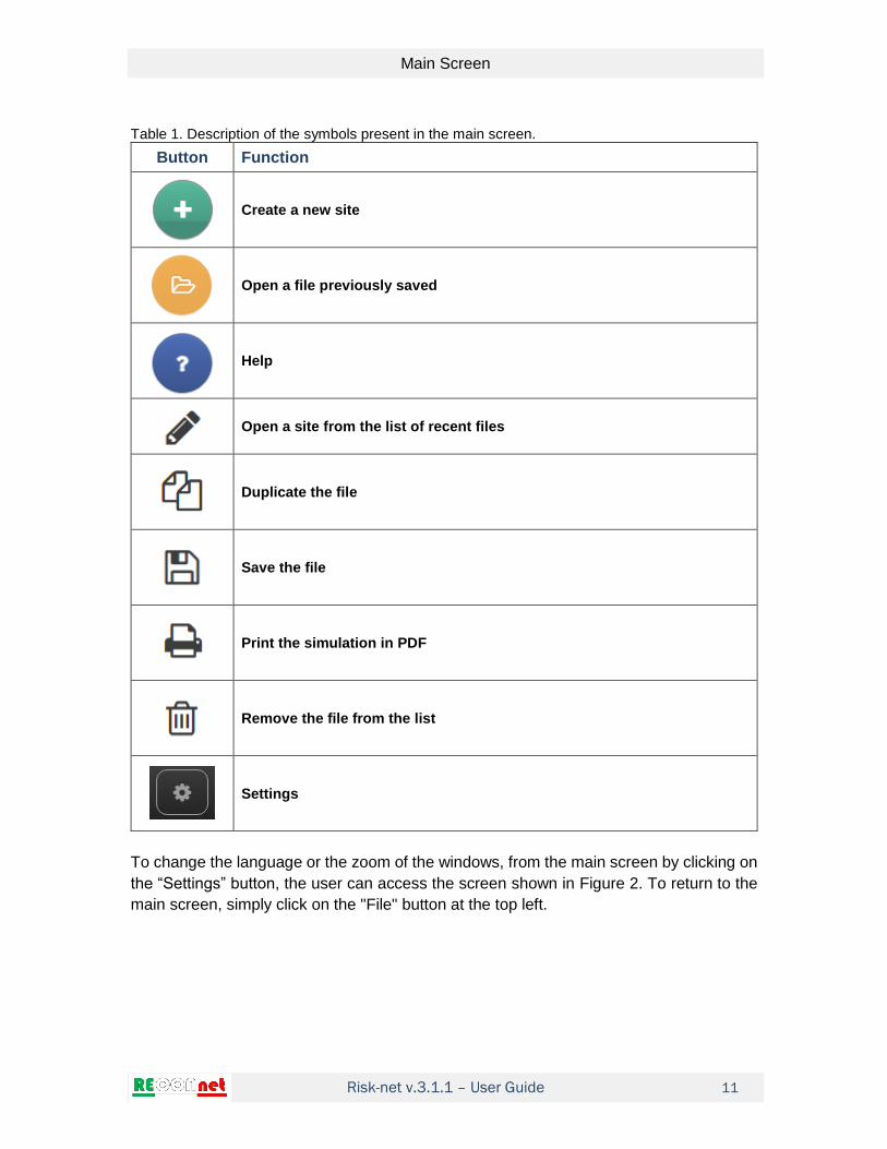
Table 1. Description of the symbols present in the main screen.
Button Function
Create a new site
Open a file previously saved
Help
Open a site from the list of recent files
Duplicate the file
Save the file
Print the simulation in PDF
Remove the file from the list
Settings
To change the language or the zoom of the windows, from the main screen by clicking on
the “Settings” button, the user can access the screen shown in Figure 2. To return to the
main screen, simply click on the "File" button at the top left.

Risk-net v.3.1.1 – User Guide
Main Screen
12
Figure 2. Main Settings.

Risk-net v.3.1.1 – User Guide
Simulation Screen
13
SIMULATION SCREEN
When opening a new file, the user accesses the screen shown in Figure 3. On this screen,
using the lateral menu, the user can quickly access the various input and output screens.
If the software is used on computers with small screens, the side menu can be deactivated
using the button in the upper right part of the menu. In this case, the menu for
accessing the various input and output screens is positioned horizontally as shown in
Figure 4.
Figure 3. Simulation screen with activated lateral menu.
To reset the lateral menu just press the button .

Risk-net v.3.1.1 – User Guide
Simulation Screen
14
Figure 4. Simulation screen without lateral menu.
The software allows the user to open multiple simulation files as shown in Figure 5. In this
case it is possible to move from one simulation file to the other by clicking on the name of
the tab at the top of the screen. To close a simulation file, simply press the button that
appears to the right of the file name. Note that the simulation file is automatically saved in
the recent files list and therefore closing the simulation file does not result in data loss. To
save the file locally on computer the user must go back to the main screen through the
"File" button on the top left of the software screen and follow the instructions described in
the previous section.

Risk-net v.3.1.1 – User Guide
Simulation Screen
15
Figure 5. Multiple files open.

Risk-net v.3.1.1 – User Guide
Simulation Setup
16
SIMULATION SETUP
SITE DESCRIPTION
This screen (Figure 6) is accessed by clicking "Site description" on the "Setup" menu.
Figure 6. Site description.
On this screen it is possible to define the general information of the project (Name of the
site, name of the eventual sub-area, Date, and Compiled By). It should be noted that in
the list of temporary files the name of the simulation will be automatically set based on the
"Name of the site" and the name of the sub-area (in brackets) assigned on this screen.
The "Notes" box allows the user to add some notes on the compilation of the project. On
this screen it is also possible to select the type of analysis to be performed. In particular,
the user can decide whether to perform only a forward analysis for the calculation of the
risks, only the backward mode for the calculation of the clean-up levels or both. In the
event that one of the two types of analysis is deactivated (backward or forward mode) the
Risks and/or SSTL screens are not shown.

Risk-net v.3.1.1 – User Guide
Simulation Setup
17
CONCEPTUAL SITE MODEL
This screen (Figure 7) is accessed by clicking "Conceptual Site Model" on the "Setup"
menu.
Figure 7. Conceptual Site Model.
On this screen the user must define the exposure scenario by selecting the contaminated
media(s), fate and transport pathways (if any), and associated exposure routes. Namely,
the user needs to identify those pathways that are likely to be complete, based on
knowledge of the locations of impacted soil or groundwater relative to the location and
habits of people that might be exposed to the chemicals of concern.
The risks and the SSTLs can be calculated for the following secondary sources: surface
soil (0-1 m from ground level), subsurface soil (>1m) and groundwater. For each matrix the
user must activate the exposure/migration pathway and then activate the type of receptor
(on-site, off-site or both).
In Risk-net the following exposure pathways can be activated:
Surface Soil
Dermal contact
Soil ingestion

Risk-net v.3.1.1 – User Guide
Simulation Setup
18
Outdoor vapor inhalation
Indoor vapor inhalation
Outdoor particulate inhalation
Indoor particulate inhalation
Leaching to groundwater
Subsurface Soil
Outdoor vapor inhalation
Indoor vapor inhalation
Leaching to groundwater
Groundwater
Outdoor vapor inhalation
Indoor vapor inhalation
Groundwater resource protection
In this context, the term “on-site” refers to a receptor located above the source zone,
whereas “off-site” refers to a receptor at any point away from the source zone.
The different check boxes of the exposure pathways and the associated receptors are
highlighted in blue if activated. If no target is activated for an activated exposure pathway,
this is highlighted in red indicating an incomplete reconstruction of the conceptual site
model.
As to the leaching and protection of the groundwater resource, the terms POC reported on
the screen refer to the point of compliance. Thus, if the box "POC = 0 m" is activated, the
risk for the groundwater resource (if activated in the Receptors screen) in the case of
leaching from surface and subsurface soil is calculated by comparing the expected
concentrations in groundwater below the source zone (i.e. no attenuation due to
groundwater transport and dispersion) and the limit values defined by the groundwater
legislation (e.g. MCL, maximum contaminant level). It is worth noting that although the
software allows to activate both options (i.e. POC = 0 m and POC> 0 m) it is evident that
if both are activated, the final SSTLs calculated for the protection of the groundwater
resource will be those estimated considering POC = 0 m. Therefore, the user must pay
particular attention to which of the two options keep activated.
By clicking on the "Integrative characterization" tab the user accesses the screen shown
in Figure 8. On this screen, it is possible to select other monitoring data available in terms
of ambient air, soil-gas, flux chambers or leaching tests carried out on samples collected
ion the surface or subsurface soil. Here the user must also define if the results of this
integrative characterization should be used for on-site or off-site exposure.

Risk-net v.3.1.1 – User Guide
Simulation Setup
19
Figure 8. Integrative characterization.
By clicking on the "Agri-foods characterization" tab the user accesses the screen shown in
Figure 9. On this screen, the user can activate the risk assessment procedure for food
products consumption. Once the checkbox is activated, the user can enter up to 10 food
products. To insert the product, the user should enter the name.

Risk-net v.3.1.1 – User Guide
Simulation Setup
20
Figure 9. Agri-foods characterization.
RECEPTORS
This screen (Figure 9) is accessed by clicking "Receptors" on the "Setup" menu.
On this screen the user can select the receptors potentially exposed. Namely, the user
can select the following receptors:
(a) Adults and Children (Residential or Recreational use);
(b) Adults, Children, Teenagers and Seniors (Residential or Recreational use);
(c) Adult (Residential or Recreational use): Adult with a full grown body weight and
skin surface area.
(d) Child (Residential or Recreational use): Children (default age 6 and under), with a
low body weight and small skin surface area.
(e) Adult (Commercial or Industrial use): Models an adult working at a full-time job.

Risk-net v.3.1.1 – User Guide
Simulation Setup
21
In the case of option (a) and (b) for carcinogenic substances, an average calculation of
the different receptors is carried out, while for toxic substances the user can decide
whether to consider a Child (default option) or to select the most critical receptor according
to the selected exposure parameters.
Figure 10. Receptors.
If the leaching or groundwater transport was activated in the conceptual site model, on
this screen the user must select whether to calculate the risk for the groundwater resource
(i.e. comparison with MCLs) or the health risk associated to the ingestion of water.
The aforementioned operations must be carried out separately for on-site and off-site
receptors. Note that in the case in which exposure pathways for on-site or off-site targets
are not active, the relative tabs are obscured.
Risk-net v.3.1.1 – User Guide
Input
22
INPUT
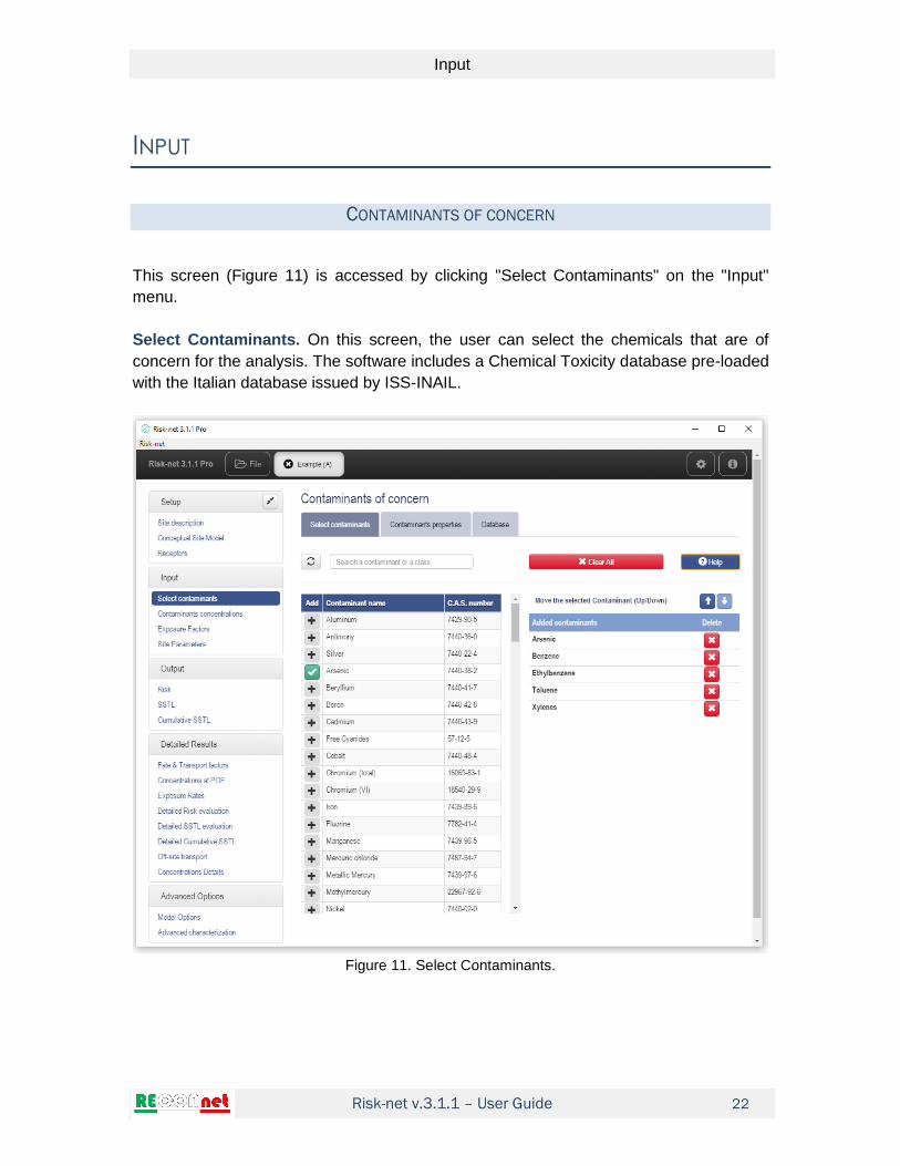
CONTAMINANTS OF CONCERN
This screen (Figure 11) is accessed by clicking "Select Contaminants" on the "Input"
menu.
Select Contaminants. On this screen, the user can select the chemicals that are of
concern for the analysis. The software includes a Chemical Toxicity database pre-loaded
with the Italian database issued by ISS-INAIL.
Figure 11. Select Contaminants.

Risk-net v.3.1.1 – User Guide
Input
23
To add the chemical of concern the user has to click on the button placed on the left of
the contaminant name (the selected contaminants are highlighted with the symbol ). To
speed up the selection of contaminants it is possible to use the "Search for a contaminant"
filter at the top left of the screen (a search can be made not only on the basis of the name
of the contaminant but also of the CAS number, contaminant class, volatility). The button
allows the user to cancel the filter used to search for a contaminant. The selected
contaminants are added in the window located to the right of the screen. Here the user
can change the order of index contaminants (selecting the contaminant of interest and
using the up and down arrows ) or remove one of the selected contaminants with the
button . The "Clear All" button allows you to quickly remove all previously entered
contaminants.
Contaminants properties. On this screen, the user can check and modify the chemico-
physical properties of the contaminants of concern.
Figure 12. Contaminants properties.

Risk-net v.3.1.1 – User Guide
Input
24
The parameters that are modified compared to the default database are highlighted in
yellow and the name of the contaminant is modified in italic and underlined. Note that the
values modified in this screen will be considered only for the current simulation. By starting
a new simulation, the values defined in the original database will be used.
If in the calculation options biodegradation is activated, on this screen the user must also
define for the different migration pathways (volatilization, leaching and groundwater
transport), the first-order biodegradation constants. Similarly, if in the calculation options
it is decided to consider bioaccessibility for calculating the soil ingestion risks on this
screen it is necessary to define the bioaccessible fraction of each contaminant. The
bioaccessible fraction can vary from a null value (not bioaccessible contaminant) to a
value 1 (corresponding to a 100% bioaccessible contaminant).
Database. Here the user can check the contaminants present in the database. By Default,
the software implements the Italian ISS-INAIL database (2018). On this screen the user
can possibly add new contaminants using the command button ‘Add contaminant’ (in this
case the name of the database will be indicated as 'modified' and the name of the modified
contaminants will be indicated as '(User)'). On this screen the user can also load external
database (button ‘‘Load external DB’) previously created using the CSV file present in the
installation folder. Note that the external database loaded in the software is not
automatically updated in the case of changes to the external CSV file and therefore in the
case where for a simulation it is decided to modify some parameters of the external
database it is necessary to repeat the database upload procedure (using the 'Load
external DB' button). By clicking on the command button ‘Load default DB’ the software
reset the original database present in the software. Note that loading an external database
the function of automatic calculation of the partition coefficients Koc and Kd as a function
pH value defined on the site is disabled.
On this screen, it is also possible to select the toxicological parameters to be used for the
vapor inhalation pathway. Specifically, the user can select to calculate the risks and
objectives of reclamation for the route of inhalation using either the reference doses (RfD
for non-carcinogens and SF for carcinogens) or the reference concentrations (RfC for non-
carcinogens and IUR for carcinogens). The main difference between the two approaches
is that the method based on the use of the reference dose (RfD) is based on a re-
modulation of the risks as a function of the body weight and the inhalation rate while the
method based on the use of reference concentrations (RfC) does not provide for
modulations based on body weight and inhalation rate. It is worth noting that the default
database present in the software is based on the use of reference concentrations (RfC for
non-carcinogens and IUR for carcinogens) and therefore to use the reference dose
method with the default database the user must enter the RfD and SF values to be used
for the risks and SSTLs calculations.
By default, according to the Italian ISS-INAIL database (2018), the software calculates the
indoor and outdoor risks only for some selected contaminants considered sufficiently
volatile. These contaminants are indicated in the database with an asterisk (VVOC *,

Risk-net v.3.1.1 – User Guide
Input
25
VOC*, SVOC*, VC* and SCV*). Therefore, by default in the software the volatilization
pathways in the simulations (Risk calculation and SSTLs) is considered only for these
contaminants. This option can be deactivated using the checkbox present on this screen.
It should be emphasized that if an external database is loaded, to use this option correctly
it is necessary to indicate in the "Vol" column the contaminants considered sufficiently
volatile (using the asterisks in the acronyms VVOC*, VOC *, SVOC *, VC * and SCV *).
It is worth noting that to modify the chemico-physical properties of the contaminants of
concern the user must enter in the screen ‘Contaminants properties’.
Figure 13. Database.
Note that by changing the database for a simulation in progress, the previously selected
contaminants are replaced with those having the same ID number in the new database. If
in the new database a previously selected contaminant is not present (i.e. in the new
database there is no contaminant with the same ID), the software for that specific
contaminant, maintains the chemical-physical and toxicological parameters present in the
database used in the old simulation.
Risk-net v.3.1.1 – User Guide
Input
26
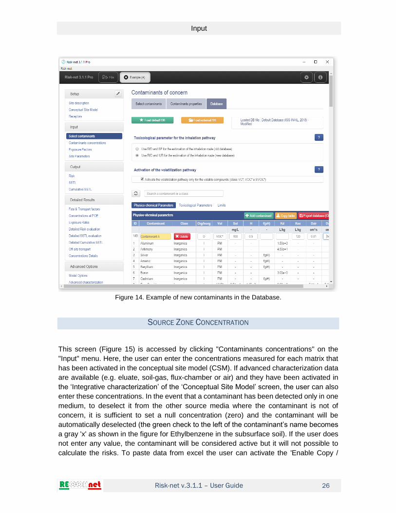
Figure 14. Example of new contaminants in the Database.
SOURCE ZONE CONCENTRATION
This screen (Figure 15) is accessed by clicking "Contaminants concentrations" on the
"Input" menu. Here, the user can enter the concentrations measured for each matrix that
has been activated in the conceptual site model (CSM). If advanced characterization data
are available (e.g. eluate, soil-gas, flux-chamber or air) and they have been activated in
the ‘Integrative characterization’ of the ‘Conceptual Site Model’ screen, the user can also
enter these concentrations. In the event that a contaminant has been detected only in one
medium, to deselect it from the other source media where the contaminant is not of
concern, it is sufficient to set a null concentration (zero) and the contaminant will be
automatically deselected (the green check to the left of the contaminant’s name becomes
a gray 'x' as shown in the figure for Ethylbenzene in the subsurface soil). If the user does
not enter any value, the contaminant will be considered active but it will not possible to
calculate the risks. To paste data from excel the user can activate the 'Enable Copy /

Risk-net v.3.1.1 – User Guide
Input
27
Paste From Excel' box present on this screen. In this case, the user can copy the entire
column from excel and copy into the table by selecting the first row of the matrix on which
to paste the data. This operation must be repeated for each source activated by the user.
The contaminants for which the chemico-physical and/or toxicological properties have
been modified, are underlined and in italic.
Figure 15. Source Concentration.
For the concentrations in groundwater and in the eluate the user can choose whether to
enter the data expressed as µg/L or mg/L (the software will automatically convert the
concentrations to the unit of measurement required in the calculations). In a similar way
the user can enter the concentration data related to soil-gas, flow chambers and in the air
as µg /m3 or mg/m3.

Risk-net v.3.1.1 – User Guide
Input
28
EXPOSURE FACTORS
This screen (Figure 15) is accessed by clicking "Exposure Factors" on the "Input" menu.
Figure 16. Exposure Factors.
On this screen, the user must enter appropriate exposure factors for each complete
pathway. By default, this section contains the values corresponding to Italian guidelines
(ISPRA, 2008). There are different exposure factor columns representing the different
types of receptors that can be modeled with the software. These receptor types allow the
user to calculate baseline risks and cleanup levels based on different physical (e.g., skin
area, body weight, etc.) and exposure-related (e.g., soil ingestion rate, inhalation rate,
etc.) parameters.
To speed up the compilation process, the software requires only the parameters actually
used in the caluclations for the specific case based on the active exposure pathway and
selected targets. In particular, the grey cells are the data not required, while the data to be

Risk-net v.3.1.1 – User Guide
Input
29
entered are the white cells. The modified values are highlighted in yellow. With the 'Default'
button it is possible to reset the default values suggested by the Italian guidelines (Table
2).
Table 2. Default values implemented in the software (ISPRA, 2008).
Scenario Residential Industrial
Exposure Parameters Symbol UM Children Teenagers Adults Seniors Worker
General Factors
Body Weight BW kg 15 15 70 70 70
Averaging time for carcinogens
AT y 70
Exposure duration ED y 6 10 24 5 25
Exposure Frequency EF d/y 350 350 350 350 250
Accidental Soil Ingestion
Ingested Soil Fraction FI - 1 1 1 1 1
Soil Ingestion Rate IR mg/d 200 200 100 100 50
Dermal Contact
Skin Surface Area SA cm² 2800 2800 5700 5700 3300
Soil Dermal adherence factor AF mg/cm²/d 0.2 0.2 0.07 0.07 0.2
Outdoor Vapors and Dust inhalation
Outdoor Daily Frequency EFgo h/d 24 0.5 24 1.9 8
Outdoor Vapor Inhalation rate
Bo m³/h 0.7 0.7 0.9 0.9 2.5
Particulate Outdoor fraction Fsd - 1 1 1 1 1
Indoor Vapors and Dust inhalation
Indoor Daily Frequency EFgi h/d 24 19.6 24 22.4 8
Indoor Vapor Inhalation rate Bi m³/h 0.7 0.7 0.9 0.9 0.9
Particulate indoor fraction Fi - 1 1 1 1 1
Water Ingestion
Water Rate Ingestion IRw L/d 1 1 2 2 1
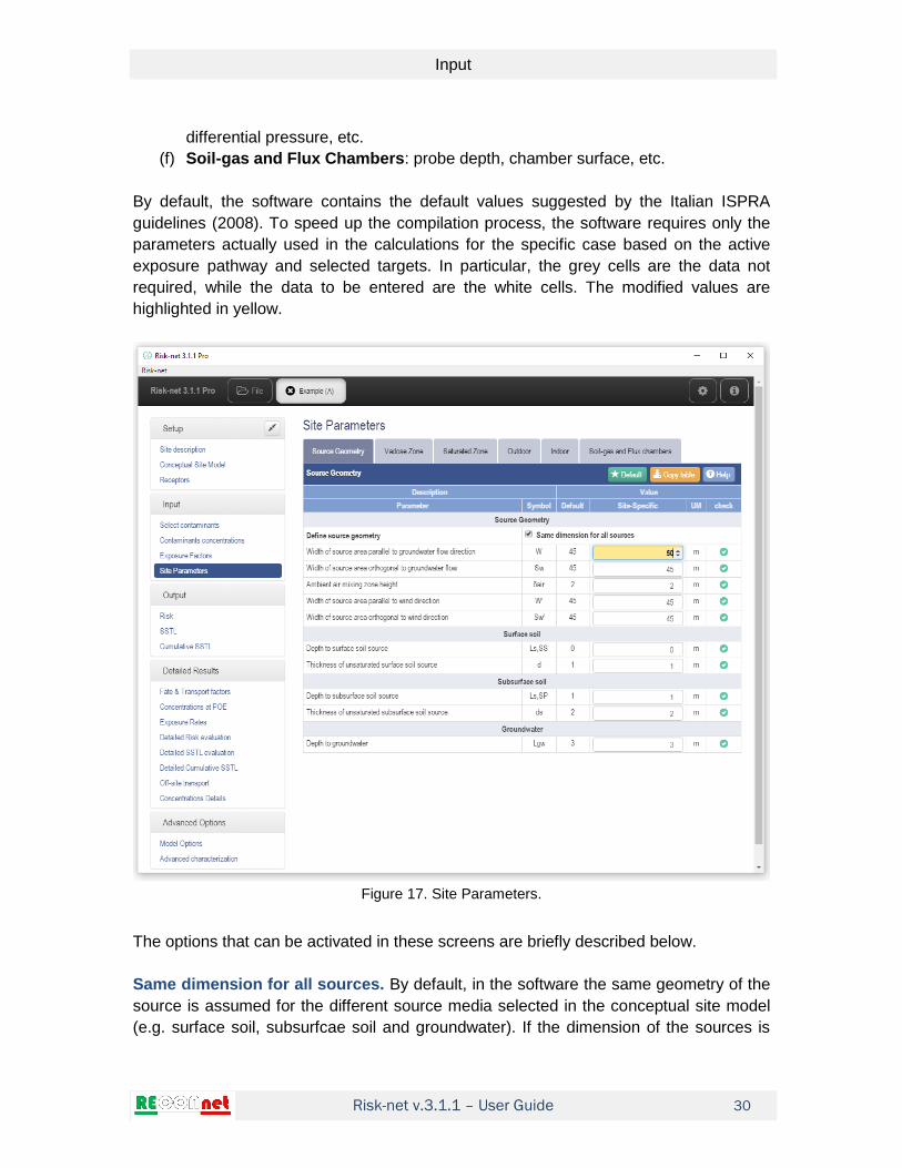
SITE PARAMETERS
This screen (Figure 15) is accessed by clicking "Site Parameters" on the "Input" menu.
In this section, the user provides the site-specific parameters required for the application
of the fate and transport models selected. Specifically, the user must enter the following
parameters:
(a) Source Geometry: source geometry in soil and groundwater.
(b) Vadose zone: soil properties, rainfall infiltration rate, fraction of organic carbon,
pH, etc.
(c) Saturated zone: physical characteristics, fraction of organic carbon and other
transport properties.
(d) Outdoor: wind speed, dispersion in air, particulate emissions, etc.
(e) Indoor: building geometry and properties, air exchange rate, indoor/outdoor
Risk-net v.3.1.1 – User Guide
Input
30
differential pressure, etc.
(f) Soil-gas and Flux Chambers: probe depth, chamber surface, etc.
By default, the software contains the default values suggested by the Italian ISPRA
guidelines (2008). To speed up the compilation process, the software requires only the
parameters actually used in the calculations for the specific case based on the active
exposure pathway and selected targets. In particular, the grey cells are the data not
required, while the data to be entered are the white cells. The modified values are
highlighted in yellow.
Figure 17. Site Parameters.
The options that can be activated in these screens are briefly described below.
Same dimension for all sources. By default, in the software the same geometry of the
source is assumed for the different source media selected in the conceptual site model
(e.g. surface soil, subsurfcae soil and groundwater). If the dimension of the sources is

Risk-net v.3.1.1 – User Guide
Input
31
different, it is possible to uncheck the checkbox "Same dimension for all sources". In this
case it is possible to enter the specific geometric parameters for each environmental
compartment.
Lens present. By activating this option, the user can take into account in the calculation
of risks and SSTLs for outdoor and indoor volatilization from subsurface soil and
groundwater for the presence of a geological vapor barrier (e.g. clay lens) placed between
the source of contamination and the ground surface. In particular, by activating the user
must define the thickness, porosity and water content of the lens. These parameters are
required to estimate molecular diffusion through this layer (for more details see the
equations in the appendix).
Soil texture. For the soil parameter the user can choose the predominant soil texture
from the drop-down menu and use the literature values indicated by Italian ISPRA
guidelines ISPRA (2008) or enter site-specific data (or other literature values) by selecting
the "Site-specific" item from the drop-down menu. Table 3 shows the default data
implemented in the software as a function of the soil texture.
Table 3. Default soil parameters values implemented in the software (ISPRA, 2008).
USDA Soil Texture Ksat θr θe θa θw θacap θwcap hcap
cm/s - - - - - - cm
SAND 8.25E-03 0.045 0.385 0.317 0.068 0.055 0.33 10
LOAMY SAND 4.05E-03 0.057 0.353 0.25 0.103 0.035 0.318 18.8
SANDY LOAM 1.23E-03 0.065 0.345 0.151 0.194 0.057 0.288 25
SANDY CLAY LOAM 3.64E-04 0.1 0.29 0.112 0.178 0.042 0.248 25.9
LOAM 2.89E-04 0.078 0.352 0.139 0.213 0.035 0.317 37.5
SILT LOAM 1.25E-04 0.067 0.383 0.128 0.255 0.086 0.297 68.2
CLAY LOAM 7.22E-05 0.095 0.315 0.115 0.2 0.027 0.288 46.9
SILTY CLAY LOAM 1.94E-05 0.089 0.341 0.095 0.246 0.024 0.317 133.9
SILTY CLAY 5.56E-06 0.07 0.29 0.016 0.274 0.008 0.282 192
SILT 6.94E-05 0.034 0.426 0.148 0.278 0.043 0.383 163
SANDY CLAY 3.33E-05 0.1 0.28 0.052 0.228 0.028 0.252 30
CLAY 5.56E-05 0.068 0.312 0.008 0.304 0.004 0.308 81.5
Soil Infiltration Rate. The user can choose whether to calculate this parameter according
to the rainfall and the type of soil selected (using the empirical equations proposed by the
ISPRA document (2008) and reported in the appendix of the manual) or enter it manually.
HDPE or low-permeability layer present. By activating this option, the user can define
the characteristics of an HDPE sheet present above the source of contamination or of a
low-permeability layer between the source and the aquifer. These data are used in the
software to calculate the effective soil infiltration rate for the leaching pathway. The

Risk-net v.3.1.1 – User Guide
Input
32
equations used for these estimates are reported in the appendix and refer to the models
described in the guidelines on risk analysis for landfills prepared by ISPRA (2005). Note
that the HDPE sheet and the low permeability layer inserted in this screen are used
exclusively for the leaching pathway (i.e. data not considered for the volatilization
pathway).
Dispersivity in groundwater. The user can choose whether to enter them manually or
calculate them based on the distance from the point of compliance (for more details, see
the equations in the appendix).
Calculate wind speed. The wind speed to be entered into the software must refer to the
height of the mixing zone in the air (which by default is set equal to 2 m height from the
ground surface). If the data available for wind speed refer to a different height (e.g. 10 m)
it is possible to calculate the expected value at the height of interest using the empirical
equations reported in the ISPRA document (see appendix of the manual).
Air dispersion coefficient. The user can choose whether to enter them manually or
calculate them according to the stability class and the distance of the off-site receptors
using the empirical equations reported by Briggs (1973).
Pressure difference between outdoor and indoor. If the convective transport of vapors
within the indoor environment is relevant at the site of concern, the user must enter a
value of "Δp" greater than zero and enter the additional parameters required.
Site-specific indoor convective flow. If available, the user can enter a site-specific
value of the convective airflow entering the building.
Empirical soil-gas attenuation factor of soil-gas. For soil-gas data, instead of the
analytical models implemented in the software, by activating this option the user can enter
empirical attenuation factors to be used for the calculation of the risks for the indoor and
outdoor vapor inhalation pathway.

Risk-net v.3.1.1 – User Guide
Model options
33
MODEL OPTIONS
By default, Risk-net implements the equations and calculation criteria outlined in the
Italian ISPRA guidelines (2008). However, to make the tool more versatile it is possible
to activate and define some supplementary calculation options. To view or modify the
active options, the user must access the "Model options" from the "Advanced Options"
menu (Figure 19). These options are divided into the following tabs: "Volatilization",
"Leaching", "Groundwater dispersion", "Csat", "Exposure" and "Limits".
Figure 18. Site Parameters.
The different options are briefly described below.
Risk-net v.3.1.1 – User Guide
Model options
34
VOLATILIZATION
Source depletion. By activating this option, the software accounts, through a mass
balance, for the source depletion. In particular, the outdoor and indoor volatilization is
calculated by selecting, for each contaminant, the smaller value obtained from the fate
and transport factor and the mass balance equation. For more details, readers are directed
to the appendix with the description of the equations implemented in the software.
Outdoor Volatilization from Surface Soil. By activating this option, if the source in the
surface soil is at some depth below the ground surface, the volatilization factor is calculated
by employing the model for the subsurface soil.
Outdoor Volatilization from Subsurface Soil. By activating this option, for contaminated
subsurface soil, the software checks if the volatilization estimated by the model is higher
than the one expected from the surface soil (and in this case select the latter as
representative of the volatilization from soil).
Off-Site Outdoor Volatilization from groundwater. For contaminated groundwater, the
off-site transport of vapors can be modelled considering volatilization from the source and
dispersion in atmosphere (ADF) or groundwater transport (DAF) and volatilization.
Biodegradation during volatilization. By activating this option, it is possible to account
for aerobic biodegradation of vapors in the subsurface. In this case, the user must define
the biodegradation kinetic constant in the screen with the chemical properties of selected
contaminants and the thickness of the aerobic zone in the screen with the definition of site-
specific parameters.
LEACHING
Source depletion. By activating this option, the software accounts, through a mass
balance, for the source depletion. In particular, the leaching factor is calculated by
selecting, for each contaminant, the smaller value obtained from the fate and transport
factor and the mass balance equation.
Soil Attenuation Model (SAM). The SAM (Connor, 1997) corrects the equilibrium soil
leachate concentration for the effect of sorptive mass loss as the leachate percolates
downward toward the underlying water-bearing unit. For the SAM, the affected soil zone
is characterized as a finite source mass equivalent to the affected soil mass times the
representative constituent concentration. Prior to reaching groundwater, percolating
rainwater serves to redistribute this finite source mass throughout the full thickness of the

Risk-net v.3.1.1 – User Guide
Model options
35
surface soil column.
Biodegradation during leaching to groundwater. By activating this option, it is possible
to account for biodegradation during the leaching in the unsaturated zone. In this case the
user must define the biodegradation kinetic constant in the screen with the chemical
properties of selected contaminants.
GROUNDWATER DISPERSION
Groundwater Dispersion. For the transport of contaminants in groundwater the user can
select the type of equation to be used as a function of the expected dispersion. In
particular, it is possible to simulate the dispersion of contaminants as:
DAF1 = dispersion in all directions (x, y, z);
DAF2 = in this case it is assumed that there is transversal and longitudinal
dispersion in all directions while the vertical dispersion is assumed to take place
only downwards;
DAF3 = in this case it is assumed that there is only longitudinal and transversal
dispersion (i.e. no vertical dispersion).
The implemented equations are reported in the appendix.
Check on the groundwater mixing zone height. By activating this option, the software
automatically uses the DAF3 in the case that the calculated thickness of the mixing zone
coincides with the thickness of the aquifer.
Biodegradation during groundwater transport. By activating this option, it is possible to
account for biodegradation during the transport of contaminants in groundwater. In this
case the user must define the biodegradation kinetic constant in the screen with the
chemical properties of selected contaminants.
CSAT
Saturation Concentration (Csat). If this option is activated by the user, the software
calculates the saturation concentration in the soil (Csat) at which the contaminant reaches
the solubility value in the dissolved phase and the vapor pressure in the soil-gas. In this
case, for the indirect exposure pathways (volatilization and leaching) for saturation
conditions (i.e. CRS> Csat) the risks are calculated assuming as the solubility value in the
dissolved phase and the vapor pressure in the soil-gas. For the direct exposure pathways
(i.e. soil ingestion and dermal contact) these concentrations, although higher the
saturation concentration does not affect the estimation of the risks as the receptor might

Risk-net v.3.1.1 – User Guide
Model options
36
be exposed also to the separate phase. With regard to the calculation of the clean-up
levels, if the calculated SSTL are higher than the Csat value in the output screen these
values are not shown but it is indicated that the SSTL are higher than Csat (indicated as
‘> Csat’). Indeed, the achievement of SSTL > Csat indicates for the indirect exposure
pathways (volatilization and leaching) even at the maximum concentration at which the
contaminant can leach (solubility) or volatilize (vapor pressure) the risks are below the
acceptable levels (e.g. R = 10-6 or HI = 1). In the event that the Csat option is deselected,
a sub-option can be activated in which the Csat is verified only in the calculation of the
SSTL but not in the direct calculation of the Risk (i.e. the CRS is not limited to the Csat).
This sub-option, although can lead to inconsistent results in the two calculation modes
(Risk Calculation and Calculation of SSTL), has been planned to replicate the results of
other available software (e.g. RBCA ToolKit) that only perform the verification of the Csat
in the calculation of the SSTL but not in the calculation of the Risk.
Source depletion. By activating this option, in the mass balance used for the estimation
of the source depletion the software accounts for the presence (if any) of separate phase
in the subsurface.
EXPOSURE
Adjustement factor for carcinogenic parameters of children (ADAF). By activating
this option, the software applies an adjustment factor (ADAF) to the toxicological
parameters (carcinogenic effects) used for the estimation of risks and clean-up levels in
the case of children as receptors. The values of ADAF used by the software can be
modified in the screen with the definition of the toxicological parameters for the selected
contaminants.
RfD vs RfC. For the inhalation pathway, the user can select the method to be used for the
estimation of the risks and of the clean-up levels. The software employs two methods. The
first is based on the use of a reference dose (RfD and SF) and the risks are calculated as
a function of the body weight and of the inhalation rate. The second method is based on
the use of a reference concentration without any adjustment for the body weight or the
inhalation rate.
Bioaccessibility. For the soil ingestion pathway, by activating this option, the software
accounts in the estimation of risks and SSTLs for the bioaccessibile fraction. The
bioaccessible fraction can be defined in the screen that reports the chemico-physical
properties of the contaminants of concern

Risk-net v.3.1.1 – User Guide
Model options
37
LIMITS
Limits. Here the user can set the acceptable individual (single contaminant) and
cumulative (multiple contaminants) acceptable risk (carcinogenic effects) and hazard
index (non-carcinogenic effects).
ADVANCED SITE CHARACTERIZATION
This screen (Figure 15) is accessed by clicking "Advanced Characterization" on the
"Advanced Options" menu.
Figure 19. Advanced Site Characterization.
By default, the results from the advanced characterization of the site are only used to

Risk-net v.3.1.1 – User Guide
Model options
38
estimate the risks for human health and environment for the selected receptor. In this
screen the user can decide if these data must be used also for the estimation of the clean-
up levels in the surface soil, subsurface soil and in groundwater. In this case, these data
are used to calculate a semi-empirical fate and transport factor that is used for the update
of the clean-up levels calculated based only on mathematical modelling. For more details,
readers are directed to the appendix with the description of the equations implemented
in the software.

Risk-net v.3.1.1 – User Guide
Output
39
OUTPUT
RISK
This screen (Figure 20) is accessed by clicking "Risk" on the "Ouptut" menu.
Figure 20. Baseline Risks.
This screen shows the risks for human health (R and HI) individual (for the single
contaminant) and cumulative (total, calculated as the sum of the risks of each selected
contaminant) and the risks for the groundwater resources (Rgw) calculated for each
source selected in the conceptual site model. In red are highlighted the risks higher than
the acceptable limits. In purple are highlighted the source concentrations that are higher
than the saturation concentration (or the solubility for the contamination in groundwater).
On this screen the user can calculate, iteratively, the concentration in the source that

Risk-net v.3.1.1 – User Guide
Output
40
ensures acceptable risks by entering a correction factor for each contaminant in the
column 'f'. The "Copy table" command allows the user to copy and paste in Word or Excel
the output table (maintaining the table formatting). The contaminants for which the
chemico-physical and/or toxicological properties have been modified, are underlined and
in italic.
Table 4 describes the different keywords and symbols related to the calculation of the
Risk.
Table 4. Nomenclature in the ‘Risk’ screen.
SYMBOL DEFINITION
CRS Source Concentration
f Reduction factor for CRS
R (HH) Carcinogenic Risk (human health)
HI Hazard Index, non-carcinogenic (human health)
Rgw Risk for the groundwater resource
Csat Saturation concentration
Cres Residual Concentration (screening NAPL)
Sol Solubility
SITE-SPECIFIC TARGET LEVELS (SSTL)
This screen (Figure 21) is accessed by clicking "SSTL" on the "Ouptut" menu.
This screen shows the maximum acceptable concentration in the affected source medium
(i.e. the Site-Specific Target Levels, SSTL) for each contaminant of concern that ensures
acceptable individual risks for human health (R and HI) and for the groundwater resources
(Rgw). In red are highlighted the contaminant for which the source concentration is higher
than the calculated SSTL. In yellow are highlighted the SSTL that are lower than the PRG
(Preliminary Remediation Goals) values defined in the database. In purple are highlighted
the source concentrations that are higher than the saturation concentration (or the
solubility for the contamination in groundwater). The "Copy table" command allows the
user to copy and paste in Word or Excel the output table (maintaining the table
formatting). The contaminants for which the chemico-physical and/or toxicological
properties have been modified, are underlined and in italic.

Risk-net v.3.1.1 – User Guide
Output
41
Figure 21. Site-Specific Target Levels (SSTL).
Table 5 describes the different keywords and symbols related to the calculation of the
SSTLs.
Table 5. Nomenclature in the ‘SSTL’ screen.
SYMBOL DEFINITION
CRS Source Concentration
SSTL (HH) Site-Specific Target Levels for human health
SSTL (GW) Site-Specific Target Levels for the groundwater resource
Csat Saturation concentration
Cres Residual Concentration (screening NAPL)
Sol Solubility
PRG Preliminary Remediation Goals

Risk-net v.3.1.1 – User Guide
Output
42
CUMULATIVE SSTL
This screen (Figure 22) is accessed by clicking "Cumulative SSTL" on the "Ouptut" menu.
Figure 22. Cumulative Site-Specific Target Levels (SSTL).
From this screen the user can check whether the individual SSTL (SSTLind) calculated
for each contaminant ensures acceptable cumulative risks (related to the simultaneous
presence of several substances). If the cumulative risks are not acceptable (cells in red)
the user should reduce SSTLind until to find a SSTL that ensures the respect of both the
individual and cumulative risks. This can be done by iteratively operating on the
adjustment factor in the column 'f' column until to get acceptable cumulative risks. The
button 'auto' in the column 'f' automatically insert a correction factor equal to the number
of contaminants selected (very conservative option). The reduced SSTL (SSTL / f), that
ensures the respect of both the individual and cumulative risks, represents the cumulative
SSTL (SSTL cum). The contaminants for which the chemico-physical and/or toxicological
properties have been modified, are underlined and in italic.

Risk-net v.3.1.1 – User Guide
Output
43
Table 6 describes the different keywords and symbols related to the calculation of the
Cumulative SSTLs.
Table 6. Nomenclature in the ‘Cumulative SSTL’ screen.
SYMBOL DEFINITION
CRS Source Concentration
f Reduction factor for SSTL
R (HH) Carcinogenic Risk (human health)
HI Hazard Index, non-carcinogenic (human health)
Rgw Risk for the groundwater resource
Csat Saturation concentration
Cres Residual Concentration (screening NAPL)
Sol Solubility
SSTLind Individual Site-Specific Target Levels
SSTLcum Cumulative Site-Specific Target Levels (SSTLind/f)
PRG Preliminary Remediation Goals
SSTLs Hydrocarbons. If in the contaminants of concern the user select hydrocarbons
compounds classified as MADEP or TPH WG, in the Cumulative SSTL screen the user
can find a a further table with the SSTLs calculated for "Hydrocarbons C>12" and
"Hydrocarbons C<12" and "Total hydrocarbons". This screen shows the SSTL for Light
(C <12), Heavy (C> 12) and Total Hydrocarbons (TOT) calculated with the ‘critical
fraction’ method based on the different hydrocarbons classes selected by the user.
Specifically, the calculation is performed for both MADEP and TPHCWG speciation. The
most critical class is identified as a function of the SSTL calculated for each class and the
fraction of the class presents in the mixture (estimated on the basis of the concentration
set by the user). For more details, readers are directed to the appendix with the
description of the equations implemented in the software.

Risk-net v.3.1.1 – User Guide
Output
44
Figure 23. SSTL for TPH mixtures.

Risk-net v.3.1.1 – User Guide
Detailed results
45
DETAILED RESULTS
In addition to the main outputs described in the previous paragraphs, the user can verify
in detail the results obtained in the different calculation steps as briefly described below.
FATE & TRANSPORT FACTORS
This screen shows the fate & transport factors (FT) calculated for the migration pathways
activated in the conceptual site model. In yellow are highlighted the FT equal to the mass
balance in the source (if this option has been activated in the ‘model options’ screen). In
purple are highlighted the semi-empirical FT that were calculated based on the available
advanced characterization data (if this option has been activated in the ‘advanced
characterization’ screen). The contaminants for which the chemico-physical and/or
toxicological properties have been modified, are underlined and in italic.
Figure 24. Fate & Transport Factors.

Risk-net v.3.1.1 – User Guide
Detailed results
46
CONCENTRATIONS AT POINT OF EXPOSURE
This screen shows the concentration at the point of exposure calculated with the fate &
transport factors based on the source concentration set by the user for the different
migration pathways activated in the conceptual site model. The contaminants for which
the chemico-physical and/or toxicological properties have been modified, are underlined
and in italic.
Figure 25. Concentration at the point of exposure.
EXPOSURE RATES
This screen reports the intake rates calculated for the different exposure pathways for
each receptor activated by the user. The contaminants for which the chemico-physical
and/or toxicological properties have been modified, are underlined and in italic..

Risk-net v.3.1.1 – User Guide
Detailed results
47
Figure 26. Exposure Rates.
DETAILED RISK EVALUATION
This screen shows the risks for human health (R and HI) individual (for the single
contaminant) and cumulative (total, calculated as the sum of the risks of each selected
contaminant) and the risks for the groundwater resources (RGW) calculated for each
source selected in the conceptual site model. In red are highlighted the risks higher than
the acceptable limits. In purple are highlighted the source concentrations that are higher
than the saturation concentration (or the solubility for the contamination in groundwater).
On this screen the user can calculate, iteratively, the concentration in the source that
ensures acceptable risks by entering a correction factor for each contaminant in the
column 'f'. The contaminants for which the chemico-physical and/or toxicological
properties have been modified, are underlined and in italic.

Risk-net v.3.1.1 – User Guide
Detailed results
48
Figure 27. Detailed Risk Evaluation.
DETAILED SSTL EVALUATION
This screen shows the maximum acceptable concentration in the affected source medium
(i.e. the Site-Specific Target Levels, SSTL) for each contaminant of concern that ensures
acceptable individual risks for human health (R and HI) and for the groundwater resources
(Rgw). In red are highlighted the contaminant for which the source concentration is higher
than the calculated SSTL. In yellow are highlighted the SSTL that are lower than the PRG
(Preliminary Remediation Goals) values defined in the database. In purple are highlighted
the source concentrations that are higher than the saturation concentration (or the
solubility for the contamination in groundwater). The contaminants for which the chemico-
physical and/or toxicological properties have been modified, are underlined and in italic.

Risk-net v.3.1.1 – User Guide
Detailed results
49
Figure 28. Detailed SSTL Evaluation.
OFF-SITE TRANSPORT
This screen can be used to evaluate the off-site transport of contaminants in the
groundwater or in the atmosphere. In particular, the user must select from the pulldown
menu the contaminant and the matrix of concern. In the case of the transport in
groundwater, the graphs show the concentration of the selected contaminant as a function
of time and space. In the case of the dispersion of the contaminants in the atmosphere
the graphs show only the concentration as a function of the distance from the site. The
user can change the distances and the times at which to calculate the concentrations by
operating on the boxes reported in the table of interest.

Risk-net v.3.1.1 – User Guide
Detailed results
50
Figure 29. Off-site transport (groundwater).
Figure 30. Off-site transport (atmosphere).
Risk-net v.3.1.1 – User Guide
Detailed results
51
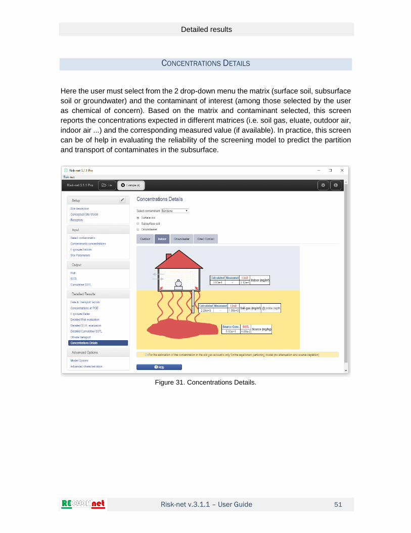
CONCENTRATIONS DETAILS
Here the user must select from the 2 drop-down menu the matrix (surface soil, subsurface
soil or groundwater) and the contaminant of interest (among those selected by the user
as chemical of concern). Based on the matrix and contaminant selected, this screen
reports the concentrations expected in different matrices (i.e. soil gas, eluate, outdoor air,
indoor air ...) and the corresponding measured value (if available). In practice, this screen
can be of help in evaluating the reliability of the screening model to predict the partition
and transport of contaminates in the subsurface.
Figure 31. Concentrations Details.

Risk-net v.3.1.1 – User Guide
References
52
REFERENCES
ASTM (1995). Standard Guide for Risk- Based Corrective Action Applied at
Petroleum Release Sites. American Society for Testing and Materials, West
Conshohocken, PA, E 1739–95 (1995, Re-approved 2015).
ASTM (2000). Standard Guide for Risk-Based Corrective Action. American
Society for Testing and Materials. Standard E2081-00. West Conshohocken, PA
(200, Re-approved 2015).
Briggs, G. A. (1973). Diffusion estimation for small emissions. Atmospheric
Turbulence and Diffusion Laboratory, 83.
Connor, J. A., Bowers, R. L., Paquette, S. M., Newell, C. J. (1997). Soil attenuation
model for derivation of risk-based soil remediation standards. Groundwater
Services Inc., Houston, Texas, 1-34.
Connor, J., Bowers, R., McHugh, T., Spexet, A. (2007). Software guidance
manual RBCA tool kit for chemical releases. Houston, Texas, USA: GSI
Environmental Inc, 1-120.
Domenico, P. A. (1987). An analytical model for multidimensional transport of a
decaying contaminant species. Journal of Hydrology, 91(1-2), 49-58.
Domenico, P. A., Schwartz, F. W. (1998). Physical and chemical hydrogeology
(Vol. 506). New York: Wiley.
Green, W.H., Ampt, G.A. (1911). Studies in Soil Physics. I. The Flow of Air and
Water through Soils. Journal of Agricultural Science, 4, 1-24.
ISPRA (2008). Methodological Criteria for Absolute Risk Analysis Application at
Contaminated Sites. Italian Environmental Protection Agency and Technical
Services. Available at: www.isprambiente.it.
ISS-INAIL (2018). Database for environmental health risk analysis. Available at:
www.iss.it
Johnson, P. C., Ettinger, R. A. (1991). Heuristic model for predicting the intrusion
rate of contaminant vapors into buildings. Environmental Science & Technology,
25(8), 1445-1452.
SNPA (2018). Design of vapour monitoring in contaminated sites and related

Risk-net v.3.1.1 – User Guide
References
53
Appendices. SNPA Guidelines 15/2018.
SNPA (2018). Procedure for the evaluation and use of soil gas data in the risk
assessment of contaminated sites. SNPA Guidelines 17/2018.
TPHCWG (1997). A Risk-Based Approach for the Management of Total
Petroleum Hydrocarbons in Soil. Total Petroleum Hydrocarbon Criteria Working
Group.
U.S. EPA (2015). Assessing and Mitigating the Vapor Intrusion Pathway from
Subsurface Vapor Sources to Indoor Air. OSWER Publication 9200.2-154
Verginelli, I., Baciocchi, R. (2014). Vapor intrusion screening model for the
evaluation of risk-based vertical exclusion distances at petroleum contaminated
sites. Environmental science & technology, 48(22), 13263-13272.

Risk-net v.3.1.1 – User Guide
Appendices – Equations and Modeling Procedures
54
APPENDICES – EQUATIONS AND MODELING PROCEDURES

Risk-net v.3.1.1 – User Guide
App. 1a. Risk Calculation (Soil and groundwater)
55
APP. 1A. RISK CALCULATION (SOIL AND GROUNDWATER)
Individual Risk. The estimation of risks for human health, correlated to exposure to a
contaminant, is calculated in the software by applying the following equations:
R E SF Risk for carcinogenic contaminants
/HI E RfD Hazard Index for non-carcinogenic contaminants
Where E is the daily chronic contaminant exposure rate, SF the slope factor (i.e. the
probability of incremental cancer case occurrence per unit dose) and RfD the reference
dose (i.e. the daily exposure rate that does not induce adverse effects on humans during
the entire life).
The chronic daily contaminant assumption, E, is given by multiplying the concentration of
the contaminant at the point of exposure, Cpoe, with the effective exposure rate EM (e.g.
the daily ingested soil amount or inhaled air volume per unit body weight)
poeE C EM
The concentration at the point of exposure, Cpoe, may be calculated by applying the
following equation:
poeC FT CRS
where CRS is the representative source concentration and FT the fate and transport factor
used for the selected migration pathway.
Combining these equations, the risk and the hazard index can be calculated as follows:
R FT CRS EM SF Risk for carcinogenic contaminants
FT CRS EMHI
RfD
Hazard Index for non-carcinogenic contaminants
This calculation is performed for the different exposure and migration pathways active in
the site using the appropriate exposure and fate & transport factors (for details, see the
tables below). The equations for the calculation of the different fate and transport factors
(FT) are reported in Appendix 3. The equations for the calculation of the different intake
rates are reported in Appendix 4.

Risk-net v.3.1.1 – User Guide
App. 1a. Risk Calculation (Soil and groundwater)
56
Note that the above equations are those reported in the ISPRA guidelines (2008) that are
based on the use of the Reference Dose (RfD) and the Slope Factor (SF). However, for
the inhalation pathway the software allows the user to use the approach based on the
Reference Concentration (RfC) and the Inhalation Unit Risk (IUR) using the following
equations:
R FT CRS EC IUR Risk for carcinogenic contaminants
FT CRS ECHI
RfC Hazard Index for non-carcinogenic contaminants
In the following tables, the equations implemented in the software are distinguished as
“reference dose method” and “reference concentration method”
Multiple exposure pathways. The following report the criteria used in the software for
the calculation of the individual risk for each media of concern accounting for multiple
exposure pathways.
Figure 32. Risk – Surface soil. Multiple exposures.
Soil Ingestion
Dermal Contact
Outdoor Vapor
Inhalation
Outdoor Dust
Inhalation
Outdoor Risk
(on-site)
Ou
tdo
or
On
-Sit
e
Indoor Vapor
Inhalation
Indoor Dust
Inhalation
Indoor Risk
(on-site)
Ind
oo
r
On
-Sit
e
Outdoor Vapor
Inhalation
Outdoor Dust
Inhalation
Ou
tdo
or
Off
-Sit
e
Leaching to
Groundwater
Off -site
Leaching to
Groundwater
On-site
Lis
civ
iazio
ne
Outdoor Risk
(of f -site)
Leaching
(On-site)
Leaching
(On-site)
Higher Risk valueIndividual Risk
Surface Soil
SURFACE SOIL

Risk-net v.3.1.1 – User Guide
App. 1a. Risk Calculation (Soil and groundwater)
57
Figure 33. Risk – Subsurface soil. Multiple exposures.
Figure 34. Risk – Groundwater. Multiple exposures.
Cumulative Risk. The cumulative risk is calculated as the sum of the incremental risk
(Ri and HIi) values associated to each contaminant of concern (i) as follows:
1
Cumulative risk for carcinogenic contaminantsn
tot i
i
R R
Outdoor Vapor
Inhalation
Outdoor Risk
on-site
Indoor Vapor
Inhalation
Indoor Risk
on-site
Outdoor Vapor
Inhalation (of f-site)
Leaching to groundwater
Off -site
Leaching to groundwater
On-site
Outdoor Risk
of f -site
Leaching
on-site
Leaching
of f -site
Higher Risk valueIndividual Risk
Subsurface Soil
SUBSURFACE SOIL
Outdoor Vapor
Inhalation
Outdoor Risk
on-site
Indoor Vapor
Inhalation
Indoor Risk
on-site
Outdoor Vapor
Inhalation (of f-site)
Af fected groundwater
Off -site
Af fected groundwater
On-site
Outdoor Risk
of f -site
Af fected
groundwater
on-site
Groundwater
transport
of f -site
Higher Risk valueIndividual Risk
Groundwater
GROUNDWATER
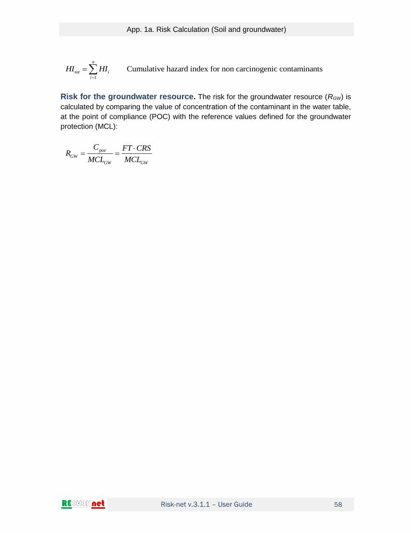
Risk-net v.3.1.1 – User Guide
App. 1a. Risk Calculation (Soil and groundwater)
58
1
Cumulative hazard index for non carcinogenic contaminantsn
tot i
i
HI HI
Risk for the groundwater resource. The risk for the groundwater resource (RGW) is
calculated by comparing the value of concentration of the contaminant in the water table,
at the point of compliance (POC) with the reference values defined for the groundwater
protection (MCL):
poe
GW
GW GW
C FT CRSR
MCL MCL

Risk-net v.3.1.1 – User Guide
App. 1a. Risk Calculation (Soil and groundwater)
59
Table 7. Surface Soil: Risk and Hazard Index
Soil Ingestion (no off-site) 6
.
6
.
10
10
SS IngS Ing IngS
IngS
SS IngS
Ing
R CRS SF EM kg mg
EM kg mgHI CRS
RfD
R = Carcinogenic Risk HI = Hazard Index CRS = Source Concentration SFIng = Slope factor - ingestion RfD Ing = Reference dose - ingestion EMIngs = Soil Ingestion rate
Dermal Contact (no off-site)
6
.
6
.
10
10
Ing ConDSS ConD
ConDSS ConD
Ing
R CRS SF EM kg mg
EM kg mgHI CRS
RfD
R = Carcinogenic Risk HI = Hazard Index CRS = Source Concentration SFIng = Slope factor for ingestion RfD Ing = Reference dose - ingestion EMConD = Dermal contact rate
Outdoor Vapor Inhalation (reference dose method)
.
.
SS InaO Ina InaO ss
InaO ssSS InaO
Ina
R CRS SF EM VF ADF
EM VF ADFHI CRS
RfD
R = Carcinogenic Risk HI = Hazard Index CRS = Source Concentration SFIna = Slope factor - inhalation RfD Ina = Reference dose - inhalation EMInaO = Outdoor inhalation rate VFss = Outdoor volatilization factor ADF = Atmospheric dispersion factor
Outdoor Vapor Inhalation (reference concentration method)
.
.
SS InaO Ina InaO ss
InaO ssSS InaO
Ina
R CRS IUR EC VF ADF
EC VF ADFHI CRS
RfC
R = Carcinogenic Risk HI = Hazard Index CRS = Source Concentration IURIna = Inhalation Unit Risk RfCIna= Reference concentration ECInaO = Outdoor inhalation rate VFss = Outdoor volatilization factor ADF = Atmospheric dispersion factor
Outdoor Dust Inhalation (reference dose method)
.
.
SS InaOP Ina InaO
InaOSS InaOP
Ina
R CRS SF EM PEF ADF
EM PEF ADFHI CRS
RfD
R = Carcinogenic Risk HI = Hazard Index CRS = Source Concentration SFIna = Slope factor - inhalation RfD Ina = Reference dose - inhalation EMInaO = Outdoor inhalation rate PEF = Partculate emission factor ADF = Atmospheric dispersion factor
Outdoor Dust Inhalation (reference concentration method)
.
.
SS InaOP InaO
InaOSS InaOP
R CRS IUR EC PEF ADF
EC PEF ADFHI CRS
RfC
R = Carcinogenic Risk HI = Hazard Index CRS = Source Concentration IURIna = Inhalation Unit Risk RfCIna= Reference concentration ECInaO = Outdoor inhalation rate PEF = Partculate emission factor ADF = Atmospheric dispersion factor
Outdoor cumulative risk
. . . . .
. . . . .
SS outdoor SS IngS SS ConD SS InaO SS InaOP
SS outdoor SS IngS SS ConD SS InaO SS InaOP
R R R R R
HI HI HI HI HI

Risk-net v.3.1.1 – User Guide
App. 1a. Risk Calculation (Soil and groundwater)
60
Table 7. Surface Soil: Risk and Hazard Index
Indoor Vapor Inhalation (no off-site) (reference dose method)
.
.
SS InaI Ina InaI ssesp
InaI ssesp
SS InaI
Ina
R CRS SF EM VF
EM VFHI CRS
RfD
R = Carcinogenic Risk HI = Hazard Index CRS = Source Concentration SFIna = Slope factor - inhalation RfD Ina = Reference dose - inhalation EMInaI = Indoor inhalation rate VFsesp = Indoor volatilization factor
Indoor Vapor Inhalation (no off-site) (reference concentration method)
.
.
SS InaI Ina InaI ssesp
InaI ssesp
SS InaI
Ina
R CRS IUR EC VF
EC VFHI CRS
RfC
R = Carcinogenic Risk HI = Hazard Index CRS = Source Concentration IURIna = Inhalation Unit Risk RfCIna= Reference concentration ECInaI = Indoor inhalation rate VFsesp = Indoor volatilization factor
Indoor Dust Inhalation (no off-site) (reference dose method)
.
.
SS InaIP Ina InaI in
InaI inSS InaIP
Ina
R CRS SF EM PEF
EM PEFHI CRS
RfD
R = Carcinogenic Risk HI = Hazard Index CRS = Source Concentration SFIna = Slope factor - inhalation RfD Ina = Reference dose - inhalation EMInaI = Indoor inhalation rate PEFin = Particulate indoor emission factor
Indoor Dust Inhalation (no off-site) (reference concentration method)
.
.
SS InaIP InaI in
InaI inSS InaIP
R CRS IUR EC PEF
EC PEFHI CRS
RfC
R = Carcinogenic Risk HI = Hazard Index CRS = Source Concentration IURIna = Inhalation Unit Risk RfCIna= Reference concentration ECInaI = Indoor inhalation rate PEFin = Particulate indoor emission factor
Indoor cumulative risk
. . .
. . .
SS Indoor SS InaI SS InaIP
SS Indoor SS InaI SS InaIP
R R R
HI HI HI
Ingestion of water
.
.
Ing IngW ss
SS LF
IngW ss
SS LF
Ing
SF EM LFR CRS
DAF
EM LFHI CRS
RfD DAF
R = Carcinogenic Risk HI = Hazard Index CRS = Source Concentration SFIng = Slope factor - ingestion RfD Ing = Reference dose - ingestion EMIngW = Water Ingestion rate LFss = Leaching factor DAF = Groundwater dilution factor
Risk and Hazard Index for surface soil
. . .
. . .
max ; ;
max ; ;
SS SS outdoor SS Indoor SS LF
SS SS outdoor SS Indoor SS LF
R R R R
HI HI HI HI
For On-site Receptors ADF = 1; DAF = 1

Risk-net v.3.1.1 – User Guide
App. 1a. Risk Calculation (Soil and groundwater)
61
Table 8. Subsurface Soil: Risk and Hazard Index
Outdoor Vapor Inhalation (reference dose method)
.
.
SP InaO Ina samb InaO
samb InaOSP InaO
Ina
R CRS SF VF EM ADF
VF EM ADFHI CRS
RfD
R = Carcinogenic Risk HI = Hazard Index CRS = Source Concentration SFIna = Slope factor - inhalation RfD Ina = Reference dose - inhalation EMInaO = Outdoor inhalation rate VFsamb = Outdoor volatilization factor ADF = Atmospheric dispersion factor
Outdoor Vapor Inhalation (reference concentration method)
.
.
SP InaO Ina samb InaO
samb InaOSP InaO
Ina
R CRS IUR VF EC ADF
VF EC ADFHI CRS
RfC
R = Carcinogenic Risk HI = Hazard Index CRS = Source Concentration IURIna = Inhalation Unit Risk RfCIna= Reference concentration ECInaO = Outdoor inhalation rate VFsamb = Outdoor volatilization factor ADF = Atmospheric dispersion factor
Indoor Vapor Inhalation (no off-site) (reference dose method)
.
.
SP InaI Ina sesp InaI
sesp InaI
SP InaI
Ina
R CRS SF VF EM
VF EMHI CRS
RfD
R = Carcinogenic Risk HI = Hazard Index CRS = Source Concentration SFIna = Slope factor - inhalation RfD Ina = Reference dose - inhalation EMInaI = Indoor inhalation rate VFsesp = Indoor volatilization factor
Indoor Vapor Inhalation (no off-site) (reference concentration method)
.
.
SP InaI Ina sesp InaI
sesp InaI
SP InaI
Ina
R CRS IUR VF EC
VF ECHI CRS
RfC
R = Carcinogenic Risk HI = Hazard Index CRS = Source Concentration IURIna = Inhalation Unit Risk RfCIna= Reference concentration ECInaI = Indoor inhalation rate VFsesp = Indoor volatilization factor
Ingestion of water
.
.
Ing IngW sp
SP LF
IngW sp
SP LF
Ing
SF EM LFR CRS
DAF
EM LFHI CRS
RfD DAF
R = Carcinogenic Risk HI = Hazard Index CRS = Source Concentration SFIng = Slope factor - ingestion RfD Ing = Reference dose - ingestion EMIngW = Water Ingestion rate LFsp = Leaching factor DAF = Groundwater dilution factor
Risk and Hazard Index for subsurface soil
. . .
. . .
max ; ;
max ; ;
SP SP InaO SP InaI SP LF
SP SP InaO SP InaI SP LF
R R R R
HI HI HI HI
For On-site Receptors ADF = 1; DAF = 1

Risk-net v.3.1.1 – User Guide
App. 1a. Risk Calculation (Soil and groundwater)
62
Table 9. Groundwater: Risk and Hazard Index
Outdoor Vapor Inhalation (reference dose method)
.
.
Ina wamb InaOGW InaO
wamb InaOGW InaO
Ina
SF VF EMR CRS
DAF
VF EMHI CRS
RfD DAF
R = Carcinogenic Risk HI = Hazard Index CRS = Source Concentration SFIna = Slope factor - inhalation RfD Ina = Reference dose - inhalation EMInaO = Outdoor inhalation rate VFwamb = Outdoor volatilization factor DAF = Groundwater dilution factor
Outdoor Vapor Inhalation (reference concentration method)
.
.
Ina wamb InaOGW InaO
wamb InaOGW InaO
Ina
IUR VF ECR CRS
DAF
VF ECHI CRS
RfC DAF
R = Carcinogenic Risk HI = Hazard Index CRS = Source Concentration IURIna = Inhalation Unit Risk RfCIna= Reference concentration ECInaO = Outdoor inhalation rate VFwamb = Outdoor volatilization factor DAF = Groundwater dilution factor
Indoor Vapor Inhalation (reference dose method)
.
.
Ina wesp InaI
GW InaI
wesp InaI
GW InaI
Ina
SF VF EMR CRS
DAF
VF EMHI CRS
RfD DAF
R = Carcinogenic Risk HI = Hazard Index CRS = Source Concentration SFIna = Slope factor - inhalation RfD Ina = Reference dose - inhalation EMInaI = Indoor inhalation rate VFwesp = Indoor volatilization factor DAF = Groundwater dilution factor
Indoor Vapor Inhalation (reference concentration method)
.
.
Ina wesp InaI
GW InaI
wesp InaI
GW InaI
Ina
IUR VF ECR CRS
DAF
VF ECHI CRS
RfC DAF
R = Carcinogenic Risk HI = Hazard Index CRS = Source Concentration IURIna = Inhalation Unit Risk RfCIna= Reference concentration ECInaI = Indoor inhalation rate VFwesp = Indoor volatilization factor DAF = Groundwater dilution factor
Ingestion of water
.
.
Ing IngW
GW D
IngW
GW D
Ing
SF EMR CRS
DAF
EMHI CRS
RfD DAF
R = Carcinogenic Risk HI = Hazard Index CRS = Source Concentration SFIng = Slope factor - ingestion RfD Ing = Reference dose - ingestion EMIngW = Water Ingestion rate DAF = Groundwater dilution factor
Risk and Hazard Index for groundwater
. . .
. . .
max ; ;
max ; ;
GW GW InaO GW InaI GW D
GW GW InaO GW InaI GW D
R R R R
HI HI HI HI
For On-site Receptors DAF = 1

Risk-net v.3.1.1 – User Guide
App. 1a. Risk Calculation (Soil and groundwater)
63
Table 10. Risk for the groundwater resource
Surface Soil – Leaching to Groundwater
.ss
SS LF
GW
CRS LFR
DAF MCL
CRS = Source Concentration MCLGW = Maximum Contaminant Level LFss = Leaching factor DAF = Groundwater dilution factor
Subsurface Soil – Leaching to Groundwater
.
sp
SP LF
GW
CRS LFR
DAF MCL
CRS = Source Concentration MCLGW = Maximum Contaminant Level LFsp = Leaching factor DAF = Groundwater dilution factor
Affected groundwater
.GW D
GW
CRSR
DAF MCL
CRS = Source Concentration MCLGW = Maximum Contaminant Level DAF = Groundwater dilution factor
For On-site Receptors DAF = 1

Risk-net v.3.1.1 – User Guide
App. 1b. Risk Calculation (Int. Characterization)
64
APP. 1B. RISK CALCULATION (INT. CHARACTERIZATION)
Table 11. Soil-gas: Risk and Hazard Index
Outdoor Vapor Inhalation (reference dose method)
.
.
SG InaO Ina samb InaO
samb InaOSG InaO
Ina
R CRS SF EM ADF
EM ADFHI CRS
RfD
R = Carcinogenic Risk HI = Hazard Index CRS = Representative Concentration SFIna = Slope factor - inhalation RfD Ina = Reference dose - inhalation EMInaO = Outdoor inhalation rate αsamb = Outdoor volatilization factor ADF = Atmospheric dispersion factor
Outdoor Vapor Inhalation (reference concentration method)
.
.
SG InaO samb InaO
samb InaOSG InaO
R CRS IUR EC ADF
EC ADFHI CRS
RfC
R = Carcinogenic Risk HI = Hazard Index CRS = Representative Concentration IURIna = Inhalation Unit Risk RfCIna= Reference concentration ECInaO = Outdoor inhalation rate αsamb = Outdoor volatilization factor ADF = Atmospheric dispersion factor
Indoor Vapor Inhalation (reference dose method)
.
.
SG InaI Ina sesp InaI
sesp InaI
SG InaI
Ina
R CRS SF EM
EMHI CRS
RfD
R = Carcinogenic Risk HI = Hazard Index CRS = Representative Concentration SFIna = Slope factor - inhalation RfD Ina = Reference dose - inhalation EMInaI = Indoor inhalation rate αsamb = Indoor volatilization factor
Indoor Vapor Inhalation (reference concentration method)
.
.
SG InaI sesp InaI
sesp InaI
SG InaI
R CRS IUR EC
ECHI CRS
RfC
R = Carcinogenic Risk HI = Hazard Index CRS = Representative Concentration IURIna = Inhalation Unit Risk RfCIna= Reference concentration ECInaI = Indoor inhalation rate αsamb = Indoor volatilization factor
For On-site Receptors ADF = 1

Risk-net v.3.1.1 – User Guide
App. 1b. Risk Calculation (Int. Characterization)
65
Table 12. Flux-Chambers: Risk and Hazard Index
Outdoor Vapor Inhalation - Concentration (reference dose method)
.
.
FC InaO Ina FC InaO
FC InaOFC InaO
Ina
R CRS SF EM ADF
EM ADFHI CRS
RfD
R = Carcinogenic Risk HI = Hazard Index CRS = Representative Concentration SFIna = Slope factor - inhalation RfD Ina = Reference dose - inhalation EMInaO = Outdoor inhalation rate αFC = Outdoor volatilization factor ADF = Atmospheric dispersion factor
Outdoor Vapor Inhalation - Flux (reference concentration method)
.
.
FC InaO FC InaO
FC InaOFC InaO
R CRS IUR EC ADF
EC ADFHI CRS
RfC
R = Carcinogenic Risk HI = Hazard Index CRS = Representative Concentration IURIna = Inhalation Unit Risk RfCIna= Reference concentration ECInaO = Outdoor inhalation rate αFC = Outdoor volatilization factor ADF = Atmospheric dispersion factor
Outdoor Vapor Inhalation - Concentration (reference dose method)
. ( )
( )
.
FC InaO Ina FC flux InaO
FC flux InaO
FC InaO
Ina
R F SF EM ADF
EM ADFHI F
RfD
R = Carcinogenic Risk HI = Hazard Index F = Measured Flux SFIna = Slope factor - inhalation RfD Ina = Reference dose - inhalation EMInaO = Outdoor inhalation rate αFC(flux) = Outdoor volatilization factor ADF = Atmospheric dispersion factor
Outdoor Vapor Inhalation - Flux (reference concentration method)
. ( )
( )
.
FC InaO FC flux InaO
FC flux InaO
FC InaO
R F IUR EC ADF
EC ADFHI F
RfC
R = Carcinogenic Risk HI = Hazard Index F = Measured Flux IURIna = Inhalation Unit Risk RfCIna= Reference concentration ECInaO = Outdoor inhalation rate αFC(flux) = Outdoor volatilization factor ADF = Atmospheric dispersion factor
For On-site Receptors ADF = 1

Risk-net v.3.1.1 – User Guide
App. 1b. Risk Calculation (Int. Characterization)
66
Table 13. Ambient Air measurements: Risk and Hazard Index
Outdoor Vapor Inhalation (reference dose method)
.
.
AR InaO Ina InaO
InaOAR InaO
Ina
R CRS SF EM ADF
EM ADFHI CRS
RfD
R = Carcinogenic Risk HI = Hazard Index CRS = Representative Concentration SFIna = Slope factor - inhalation RfD Ina = Reference dose - inhalation EMInaO = Outdoor inhalation rate ADF = Atmospheric dispersion factor
Outdoor Vapor Inhalation (reference concentration method)
.
.
AR InaO InaO
InaOAR InaO
R CRS IUR EC ADF
EC ADFHI CRS
RfC
R = Carcinogenic Risk HI = Hazard Index CRS = Representative Concentration IURIna = Inhalation Unit Risk RfCIna= Reference concentration ECInaO = Outdoor inhalation rate ADF = Atmospheric dispersion factor
Indoor Vapor Inhalation (reference dose method)
.
.
AR InaI Ina InaI
InaIAR InaI
Ina
R CRS SF EM
EMHI CRS
RfD
R = Carcinogenic Risk HI = Hazard Index CRS = Representative Concentration SFIna = Slope factor - inhalation RfD Ina = Reference dose - inhalation EMInaI = Indoor inhalation rate
Indoor Vapor Inhalation (reference concentration method)
.
.
AR InaI InaI
InaIAR InaI
R CRS IUR EC
ECHI CRS
RfC
R = Carcinogenic Risk HI = Hazard Index CRS = Representative Concentration IURIna = Inhalation Unit Risk RfCIna= Reference concentration ECInaI = Indoor inhalation rate
For On-site Receptors ADF = 1

Risk-net v.3.1.1 – User Guide
App. 1b. Risk Calculation (Int. Characterization)
67
Table 14. Eluate (Surface Soil): Risk and Hazard Index
Water Ingestion
.
.
LFss Ing IngW
ELss D
LFss IngW
ELss D
Ing
SF EMR CRS
DAF
EMHI CRS
RfD DAF
R = Carcinogenic Risk HI = Hazard Index CRS = Representative Concentration SFIng = Slope factor - ingestion RfD Ing = Reference dose - ingestion EMIngW = Water Ingestion rate αLFss = Leaching Factor DAF = Dilution Attenuation Factor
Groundwater Protection
.LFss
GW ELss
GW
CRSR
DAF MCL
CRS = Representative Concentration MCLGW = Maximum contaminant level αLFss = Leaching Factor DAF = Dilution Attenuation Factor
For On-site Receptors DAF=1
Table 15. Eluate (Subsurface Soil): Risk and Hazard Index
Water Ingestion
.
.
LFsp Ing IngW
ELsp D
LFsp IngW
ELsp D
Ing
SF EMR CRS
DAF
EMHI CRS
RfD DAF
R = Carcinogenic Risk HI = Hazard Index CRS = Representative Concentration SFIng = Slope factor - ingestion RfD Ing = Reference dose - ingestion EMIngW = Water Ingestion rate αLFsp = Leaching Factor DAF = Dilution Attenuation Factor
Groundwater Protection
.
LFsp
GW ELsp
GW
CRSR
DAF MCL
CRS = Representative Concentration MCLGW = Maximum contaminant level αLFsp = Leaching Factor DAF = Dilution Attenuation Factor
For On-site Receptors DAF=1
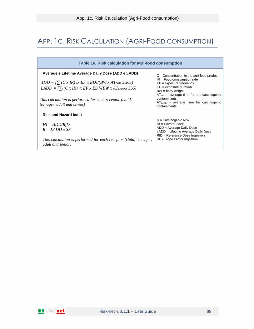
Risk-net v.3.1.1 – User Guide
App. 1c. Risk Calculation (Agri-Food consumption)
68
APP. 1C. RISK CALCULATION (AGRI-FOOD CONSUMPTION)
Table 16. Risk calculation for agri-food consumption
Average e Lifetime Average Daily Dose (ADD e LADD)
ADD = [∑i (C x IR) i x EF x ED]/(BW x ATADD x 365)
LADD = [∑i (C x IR) i x EF x ED]/(BW x ATLADD x 365)
This calculation is performed for each receptor (child,
teenager, adult and senior)
C = Concentration in the agri-food product IR = Food consumption rate EF = exposure frequency ED = exposure duration BW = body weight ATADD = average time for non-carcinogenic contaminants ATLADD = average time for carcinogenic contaminants
Risk and Hazard Index
HI = ADD/RfD R = LADD x SF
This calculation is performed for each receptor (child, teenager,
adult and senior)
R = Carcinogenic Risk HI = Hazard Index ADD = Average Daily Dose LADD = Lifetime Average Daily Dose RfD = Reference Dose Ingestion SF = Slope Factor Ingestion

Risk-net v.3.1.1 – User Guide
App. 2a. Clean-Up Levels Calculation (SSTL)
69
APP. 2A. CLEAN-UP LEVELS CALCULATION (SSTL)
The calculation of the remediation targets (Individual Site-Specific Target Levels, SSTL)
is performed by the application of the risk analysis procedure in backward mode. The
clean-up levels calculated represent the maximum acceptable concentration in the
affected source medium (soil or groundwater) that is protective of a human or groundwater
receptor located at a relevant point of exposure.
Individual Clean-up Levels (SSTL). The calculation of the clean-up levels (SSTL) is
performed using the same equations applied to calculate the risk, properly reversed and
expressed in terms of the source concentration:
poeC E TRSSTL
FT EM FT SF EM FT
carcinogenic contaminants
Cpoe E THI RfDSSTL
FT EM FT EM FT
non-carcinogenic contaminants
Where:
TR: Target Risk for the single constituent (e.g. TR = 10-6)
THI: Target Hazard Index for the single constituent (THI = 1)
E: daily chronic contaminant exposure rate
SF: Slope Factor
RfD: Reference Dose
Cpoe: Concentration at the point of exposure
EM: Intake rate
FT: Fate & Transport factor
This calculation is repeated for the different exposure and migration pathways active in
the site using the appropriate exposure factors and transport (for details, see the tables
below). The equations for the different F&T factors and intake rates are reported in the
next paragraphs.
Note that the above equations are those reported in the ISPRA guidelines (2008) that are
based on the use of the Reference Dose (RfD) and the Slope Factor (SF). However, for
the inhalation pathway the software allows the user to use the approach based on the
Reference Concentration (RfC) and the Inhalation Unit Risk (IUR) using the following
equations:

Risk-net v.3.1.1 – User Guide
App. 2a. Clean-Up Levels Calculation (SSTL)
70
TRSSTL
IUR EC FT
carcinogenic contaminants
THI RfCSSTL
EC FT
non-carcinogenic contaminants
In the following tables, the equations implemented in the software are distinguished as
“reference dose method” and “reference concentration method”
Multiple exposure pathways. The equations described above provide an assessment
of the SSTL for the single exposure pathway. The Individual SSTL (associated to the
single contaminant) is derived by cumulating the effects of the different exposure
scenarios (e.g. Outdoor exposure) and then choosing the most conservative value (i.e.
the lower value) between the SSTL calculated for the different scenarios. Namely, the
combined effect of multiple exposure is estimated as the reciprocal of the sum of the
reciprocals of the SSTL calculated for each route of exposure. Let assume, for example,
the case of SSTL for the calculation of exposure in outdoor environments:
.
1
1 1 1 1outdoor
ing derm cont dusts vapors
SSTLSSTL SSTL SSTL SSTL
(12)
For other scenarios, see the tables below.
The following figures report the criteria used in the software for the calculation of the
individual clean-up levels for each media of concern accounting for multiple exposure
pathways.
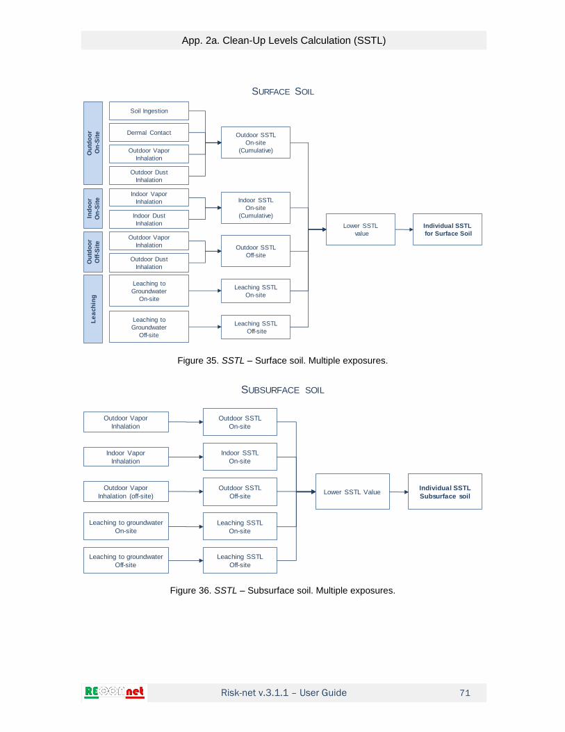
Risk-net v.3.1.1 – User Guide
App. 2a. Clean-Up Levels Calculation (SSTL)
71
Figure 35. SSTL – Surface soil. Multiple exposures.
Figure 36. SSTL – Subsurface soil. Multiple exposures.
Soil Ingestion
Dermal Contact
Outdoor Vapor
Inhalation
Outdoor Dust
Inhalation
Outdoor SSTL
On-site
(Cumulative)
Ou
tdo
or
On
-Sit
e
Indoor Vapor
Inhalation
Indoor Dust
Inhalation
Indoor SSTL
On-site
(Cumulative)Ind
oo
r
On
-Sit
e
Outdoor Vapor
Inhalation
Outdoor Dust
Inhalation
Ou
tdo
or
Off
-Sit
e
Leaching to
Groundwater
Off-site
Leaching to
Groundwater
On-site
Le
ach
ing
Outdoor SSTL
Off-site
Leaching SSTL
On-site
Leaching SSTL
Off-site
Lower SSTL
value
Individual SSTL
for Surface Soil
SURFACE SOIL
Outdoor Vapor
Inhalation
Outdoor SSTL
On-site
Indoor Vapor
Inhalation
Indoor SSTL
On-site
Outdoor Vapor
Inhalation (off-site)
Leaching to groundwater
Off-site
Leaching to groundwater
On-site
Outdoor SSTL
Off-site
Leaching SSTL
On-site
Leaching SSTL
Off-site
Lower SSTL ValueIndividual SSTL
Subsurface soil
SUBSURFACE SOIL

Risk-net v.3.1.1 – User Guide
App. 2a. Clean-Up Levels Calculation (SSTL)
72
Figure 37. SSTL – Groundwater. Multiple exposures.
Cumulative SSTL (Clean-up levels). The SSTL calculated above does not constitute
yet the remediation targets since these concentrations only meet the condition of tolerable
risk for exposure to a single contaminant. In fact, the individual SSTL does not necessarily
meet the requirement of cumulative target risk. Thus, to account for the effects of the
cumulative risk, it is necessary to further reduce the individual SSTL to ensure the
achievement of values of concentration such that the condition of acceptable cumulative
risk is met:
for carcinogenic contaminantsn
cum
i i i i
i
SSTL FT EM SF TR
for non carcinogenic contaminantscumni i i
i i
SSTL FT EMTHI
RfD
The SSTL that meet both the individual and cumulative target limits represent the site-
specific clean-up levels for the contaminated matrix.
Outdoor Vapor
Inhalation
Outdoor SSTL
On-site
Indoor Vapor
Inhalation
Indoor SSTL
On-site
Outdoor Vapor
Inhalation (off-site)
Groundwater Protection
Off-site
Groundwater Protection
On-site
Outdoor SSTL
Off-site
Groundwater
Protection SSTL
On-site
Groundwater
Protection SSTL
Off-site
Lower SSTL valueIndividual SSTL
Groundwater
GROUNDWATER

Risk-net v.3.1.1 – User Guide
App. 2a. Clean-Up Levels Calculation (SSTL)
73
Table 17. Surface Soil: SSTL
Soil Ingestion (no off-site)
6
.
. 6
10min
10
canc
Ing IngS
SS Ing
Ing
non canc
IngS
TRSSTL
SF EM kg mgSSTL
THQ RfDSSTL
EM kg mg
SSTLcanc = SSTL carcinogenic cont. SSTLnon.canc = SSTL non-carcinogenic TR = Target Risk THQ = Target Hazard Index SFIng = Slope factor - ingestion RfD Ing = Reference dose - ingestion EMIngs = Soil Ingestion rate
Dermal Contact (no off-site)
6
.
. 6
10min
10
cancIng ConD
SS ConD
Ing
non canc
ConD
TRSSTL
SF EM kg mgSSTL
THQ RfDSSTL
EM kg mg
SSTLcanc = SSTL carcinogenic cont. SSTLnon.canc = SSTL non-carcinogenic TR = Target Risk THQ = Target Hazard Index SFIng = Slope factor - ingestion RfD Ing = Reference dose - ingestion EMConD = Dermal contact rate
Outdoor Vapors Inhalation (reference dose method)
.
.
min
canc
Ina InaO ss
SS InaO
Inanon canc
InaO ss
TRSSTL
SF EM VF ADFSSTL
THQ RfDSSTL
EM VF ADF
SSTLcanc = SSTL carcinogenic cont. SSTLnon.canc = SSTL non-carcinogenic TR = Target Risk THQ = Target Hazard Index SFIna = Slope factor - inhalation RfD Ina = Reference dose – inhalation EMInaO = Outdoor inhalation rate VFss = Outdoor Volatilization factor ADF = Atmospheric dispersion factor
Outdoor Vapors Inhalation (reference concentration method)
.
.
min
canc
Ina InaO ss
SS InaO
Inanon canc
InaO ss
TRSSTL
IUR EC VF ADFSSTL
THQ RfCSSTL
EC VF ADF
SSTLcanc = SSTL carcinogenic cont. SSTLnon.canc = SSTL non-carcinogenic TR = Target Risk THQ = Target Hazard Index IURIna = Inhalation Unit Risk RfCIna= Reference concentration ECInaO = Outdoor inhalation rate VFss = Outdoor Volatilization factor ADF = Atmospheric dispersion factor
Outdoor Dusts Inhalation (reference dose method)
.
.
min
canc
Ina InaO
SS InaOP
Inanon canc
InaO
TRSSTL
SF EM PEF ADFSSTL
THQ RfDSSTL
EM PEF ADF
SSTLcanc = SSTL carcinogenic cont. SSTLnon.canc = SSTL non-carcinogenic TR = Target Risk THQ = Target Hazard Index SFIna = Slope factor - inhalation RfD Ina = Reference dose - inhalation EMInaO = Outdoor inhalation rate PEF = Particulate emission factor ADF = Atmospheric dispersion factor

Risk-net v.3.1.1 – User Guide
App. 2a. Clean-Up Levels Calculation (SSTL)
74
Table 17. Surface Soil: SSTL
Outdoor Dusts Inhalation (reference concentration method)
.
.
min
canc
Ina InaO
SS InaOP
Inanon canc
InaO
TRSSTL
IUR EC PEF ADFSSTL
THQ RfCSSTL
EC PEF ADF
SSTLcanc = SSTL carcinogenic cont. SSTLnon.canc = SSTL non-carcinogenic TR = Target Risk THQ = Target Hazard Index SFIna = Slope factor - inhalation RfD Ina = Reference dose - inhalation EMInaO = Outdoor inhalation rate PEF = Particulate emission factor ADF = Atmospheric dispersion factor
Outdoor
. . . .
.
max,
. . .
1 (for )
1 1 1 1
(for )
InaO sat
SS IngS SS ConD SS InaO SS InaOP
SS outdoor
InaO
InaO sat
SS IngS SS ConD SS InaOP
SSTL C
SSTL SSTL SSTL SSTLSSTL
TR RSSTL C
TR TR TR
SSTL SSTL SSTL
max, (for )InaO sat InaO InaO satR C SSTL TR SSTL C
Indoor Vapors Inhalation (no off-site) (reference dose method)
.
.
min
canc
Ina InaI ssesp
SS InaI
Inanon canc
InaI ssesp
TRSSTL
SF EM VFSSTL
THQ RfDSSTL
EM VF
SSTLcanc = SSTL carcinogenic cont. SSTLnon.canc = SSTL non-carcinogenic TR = Target Risk THQ = Target Hazard Index SFIna = Slope factor - inhalation RfD Ina = Reference dose - inhalation EMInaI = Indoor inhalation rate VFsesp = Indoor Volatilization factor
Indoor Vapors Inhalation (no off-site) (reference concentration method)
.
.
min
canc
Ina InaI ssesp
SS InaI
Inanon canc
InaI ssesp
TRSSTL
IUR EC VFSSTL
THQ RfCSSTL
EC VF
SSTLcanc = SSTL carcinogenic cont. SSTLnon.canc = SSTL non-carcinogenic TR = Target Risk THQ = Target Hazard Index IURIna = Inhalation Unit Risk RfCIna= Reference concentration ECInaI = Indoor inhalation rate VFsesp = Indoor Volatilization factor
Indoor Dusts Inhalation (no off-site) (reference dose method)
.
.
min
canc
Ina InaI in
SS InaIP
Inanon canc
InaI in
TRSSTL
SF EM PEFSSTL
THQ RfDSSTL
EM PEF
SSTLcanc = SSTL carcinogenic cont. SSTLnon.canc = SSTL non-carcinogenic TR = Target Risk THQ = Target Hazard Index SFIna = Slope factor - inhalation RfD Ina = Reference dose - inhalation EMInaI = Indoor inhalation rate PEFin = Particulate indoor emission factor

Risk-net v.3.1.1 – User Guide
App. 2a. Clean-Up Levels Calculation (SSTL)
75
Table 17. Surface Soil: SSTL
Indoor Dusts Inhalation (no off-site) (reference concentration method)
.
.
min
canc
Ina InaI in
SS InaIP
Inanon canc
InaI in
TRSSTL
IUR EC PEFSSTL
THQ RfCSSTL
EC PEF
SSTLcanc = SSTL carcinogenic cont. SSTLnon.canc = SSTL non-carcinogenic TR = Target Risk THQ = Target Hazard Index IURIna = Inhalation Unit Risk RfCIna= Reference concentration ECInaI = Indoor inhalation rate PEFin = Particulate indoor emission factor
Indoor
. .
.
max,
.
1 (for )
1 1
(for )
InaI sat
SS InaI SS InaIP
SS Indoor
InaI
InaI sat
SS InaIP
SSTL C
SSTL SSTLSSTL
TR RSSTL C
TR
SSTL
max, (for )InaI sat InaI InaI satR C SSTL TR SSTL C
Leaching to groundwater
.
.
min
canc
Ing IngW ss
SS LF
Ing
non canc
IngW ss
TR DAFSSTL
SF EM LFSSTL
THQ RfD DAFSSTL
EM LF
SSTLcanc = SSTL carcinogenic cont. SSTLnon.canc = SSTL non-carcinogenic TR = Target Risk THQ = Target Hazard Index SFIng = Slope factor - ingestion RfD Ing = Reference dose - ingestion EMIngW = Water ingestion rate LFss = Leaching Factor DAF = Groundwater dilution factor
SSTL – Surface Soil
. . .min ; ;SS SS outdoor SS Indoor SS LFSSTL SSTL SSTL SSTL
For On-site Receptors ADF = 1; DAF = 1

Risk-net v.3.1.1 – User Guide
App. 2a. Clean-Up Levels Calculation (SSTL)
76
Table 18. Subsurface Soil: SSTL
Outdoor Vapors Inhalation (reference dose method)
.
.
min
canc
Ina samb InaO
SP InaO
Inanon canc
samb InaO
TRSSTL
SF VF EM ADFSSTL
THQ RfDSSTL
VF EM ADF
SSTLcanc = SSTL carcinogenic cont. SSTLnon.canc = SSTL non-carcinogenic cont. TR = Target Risk THQ = Target Hazard Index SFIna = Slope factor - inhalation RfD Ina = Reference dose – inhalation EMInaO = Outdoor inhalation rate VFsamb = Outdoor Volatilization factor ADF = Atmospheric dispersion factor
Outdoor Vapors Inhalation (reference concentration method)
.
.
min
canc
Ina samb InaO
SP InaO
Inanon canc
samb InaO
TRSSTL
IUR VF EC ADFSSTL
THQ RfCSSTL
VF EC ADF
SSTLcanc = SSTL carcinogenic cont. SSTLnon.canc = SSTL non-carcinogenic cont. TR = Target Risk THQ = Target Hazard Index IURIna = Inhalation Unit Risk RfCIna= Reference concentration ECInaO = Outdoor inhalation rate VFsamb = Outdoor Volatilization factor ADF = Atmospheric dispersion factor
Indoor Vapors Inhalation (no off-site) (reference dose method)
.
.
min
canc
Ina sesp InaI
SP InaI
Inanon canc
sesp InaI
TRSSTL
SF VF EMSSTL
THQ RfDSSTL
VF EM
SSTLcanc = SSTL carcinogenic cont. SSTLnon.canc = SSTL non-carcinogenic cont. TR = Target Risk THQ = Target Hazard Index SFIna = Slope factor - inhalation RfD Ina = Reference dose – inhalation EMInaI = Indoor inhalation rate VFsesp = Indoor Volatilization factor
Indoor Vapors Inhalation (no off-site) (reference concentration method)
.
.
min
canc
Ina sesp InaI
SP InaI
Inanon canc
sesp InaI
TRSSTL
IUR VF ECSSTL
THQ RfCSSTL
VF EC
SSTLcanc = SSTL carcinogenic cont. SSTLnon.canc = SSTL non-carcinogenic cont. TR = Target Risk THQ = Target Hazard Index IURIna = Inhalation Unit Risk RfCIna= Reference concentration ECInaI = Indoor inhalation rate VFsesp = Indoor Volatilization factor
Leaching to groundwater
.
.
min
canc
Ing IngW sp
SP LF
Ing
non canc
IngW sp
TR DAFSSTL
SF EM LFSSTL
THQ RfD DAFSSTL
EM LF
SSTLcanc = SSTL carcinogenic cont. SSTLnon.canc = SSTL non-carcinogenic cont. TR = Target Risk THQ = Target Hazard Index SFIng = Slope factor - ingestion RfD Ing = Reference dose - ingestion EMIngW = Water ingestion rate LFsp = Leaching factor DAF = Groundwater dilution factor
SSTL – Subsurface Soil
. . .min ; ;SP SP InaO SP InaI SP LFSSTL SSTL SSTL SSTL
For On-site Receptors ADF = 1; DAF = 1

Risk-net v.3.1.1 – User Guide
App. 2a. Clean-Up Levels Calculation (SSTL)
77
Table 19. Groundwater: SSTL
Outdoor Vapors Inhalation (reference dose method)
.
.
min
canc
Ina wamb InaO
GW InaO
Inanon canc
wamb InaO
TR DAFSSTL
SF VF EMSSTL
THQ RfD DAFSSTL
VF EM
SSTLcanc = SSTL carcinogenic cont. SSTLnon.canc = SSTL non-carcinogenic cont. TR = Target Risk THQ = Target Hazard Index SFIna = Slope factor - inhalation RfD Ina = Reference dose – inhalation EMInaO = Outdoor inhalation rate VFwamb = Outdoor Volatilization factor DAF = Groundwater dilution factor
Outdoor Vapors Inhalation (reference concentration method)
.
.
min
canc
Ina wamb InaO
GW InaO
Inanon canc
wamb InaO
TR DAFSSTL
IUR VF ECSSTL
THQ RfC DAFSSTL
VF EC
SSTLcanc = SSTL carcinogenic cont. SSTLnon.canc = SSTL non-carcinogenic cont. TR = Target Risk THQ = Target Hazard Index IURIna = Inhalation Unit Risk RfCIna= Reference concentration ECInaO = Outdoor inhalation rate VFwamb = Outdoor Volatilization factor DAF = Groundwater dilution factor
Indoor Vapors Inhalation (reference dose method)
.
.
min
canc
Ina wesp InaI
GW InaI
Inanon canc
wesp InaI
TR DAFSSTL
SF VF EMSSTL
THQ RfD DAFSSTL
VF EM
SSTLcanc = SSTL carcinogenic cont. SSTLnon.canc = SSTL non-carcinogenic cont. TR = Target Risk THQ = Target Hazard Index SFIna = Slope factor - inhalation RfD Ina = Reference dose – inhalation EMInaI = Indoor inhalation rate VFwesp = Indoor Volatilization factor DAF = Groundwater dilution factor
Indoor Vapors Inhalation (reference concentration method)
.
.
min
canc
Ina wesp InaI
GW InaI
Inanon canc
wesp InaI
TR DAFSSTL
IUR VF ECSSTL
THQ RfC DAFSSTL
VF EC
SSTLcanc = SSTL carcinogenic cont. SSTLnon.canc = SSTL non-carcinogenic cont. TR = Target Risk THQ = Target Hazard Index IURIna = Inhalation Unit Risk RfCIna= Reference concentration ECInaI = Indoor inhalation rate VFwesp = Indoor Volatilization factor DAF = Groundwater dilution factor
Water Ingestion
.
.
min
canc
Ing IngW
GW D
Ing
non canc
IngW
TR DAFSSTL
SF EMSSTL
THQ RfD DAFSSTL
EM
SSTLcanc = SSTL carcinogenic cont. SSTLnon.canc = SSTL non-carcinogenic cont. TR = Target Risk THQ = Target Hazard Index SFIng = Slope factor - ingestion RfD Ing = Reference dose - ingestion EMIngW = Water ingestion rate DAF = Groundwater dilution factor
SSTL - Groundwater
. . .min ; ;GW GW InaO GW InaI GW DSSTL SSTL SSTL SSTL
For On-site Receptors DAF = 1

Risk-net v.3.1.1 – User Guide
App. 2a. Clean-Up Levels Calculation (SSTL)
78
Table 20. SSTL Groundwater Resource
Surface Soil – Leaching to Groundwater
.GW
SS LF
ss
MCL DAFSSTL
LF
MCLGW = Maximum contaminant level LFss = Leaching factor DAF = Groundwater dilution factor
Subsurface Soil – Leaching to Groundwater
.
gw
SP LF
sp
MCL DAFSSTL
LF
MCLGW = Maximum contaminant level LFsp = Leaching factor DAF = Groundwater dilution factor
Affected Groundwater
.GW D GWSSTL DAF MCL MCLGW = Maximum contaminant level DAF = Groundwater dilution factor
For On-site Receptors DAF = 1

Risk-net v.3.1.1 – User Guide
App. 2a. Clean-Up Levels Calculation (SSTL)
79
Table 21. SSTL: TPH Mixtures
MADEP CLASSIFICATION
Hydrocarbons C< 12
12 12 12
12 MADEP1 1 MADEP2 2 MADEPnmin / ; / ;.......; /C C C
C nSSTL SSTL f SSTL f SSTL f
Hydrocarbons C> 12
12 12 12
12 MADEP1 1 MADEP2 2 MADEPnmin / ; / ;.......; /C C C
C nSSTL SSTL f SSTL f SSTL f
Total Hydrocarbons
MADEP1 1 MADEP2 2 MADEPnmin / ; / ;.......; /HC HC HC
HC nSSTL SSTL f SSTL f SSTL f
Nomenclature
MADEPiSSTL = calculated SSTL for the i-th MADEP class
12C
if
and 12C
ifraz = mass fraction of the i-th MADEP class for C>12 and C<12
HC
if = mass fraction of the i-th MADEP class for total hydrocarbons
TPHWG CLASSIFICATION
Hydrocarbons C< 12
12 12 12
12 TPH1 1 TPH2 2 TPHnmin / ; / ;.......; /C C C
C nSSTL SSTL f SSTL f SSTL f
Hydrocarbons C> 12
12 12 12
12 TPH1 1 TPH2 2 TPHnmin / ; / ;.......; /C C C
C nSSTL SSTL f SSTL f SSTL f
Total Hydrocarbons
TPH1 1 TPH2 2 TPHnmin / ; / ;.......; /HC HC HC
HC nSSTL SSTL f SSTL f SSTL f
Nomenclature
TPHiSSTL = calculated SSTL for the i-th TPH class
12C
if
and 12C
ifraz = mass fraction of the i-th TPH class for C>12 and C<12
HC
if = mass fraction of the i-th TPHclass for total hydrocarbons

Risk-net v.3.1.1 – User Guide
App. 2a. Clean-Up Levels Calculation (SSTL)
80
Table 22. Screening for free phase migration (NAPL)
Vadose zone (ASTM E2081-00)
610w a o s s o o
NAPL
s s
H K mgRBSL S
kg
Saturated Zone (ASTM E2081-00)
, 610e sat o s s o o
NAPL
s s
K mgRBSL S
kg
Residual phase volume fraction, θo (-)
, ,o e sat r satS ; o e rS
Nomenclature Sr = Residual phase void fraction, vadose zone (-) Sr,sat = Residual phase void fraction, saturated zone (-) θw = Volumetric water content (-) θa = Volumetric air content (-) θe = Effective porosity, unsaturated zone (-) θe,sat = Effective porosity, saturated zone (-) Ks = Soil / water partition coefficient (kg/L) H = Henry constant (-) ρs = Dry soil bulk density (g/cm3) ρo = Contaminant density (g/cm3)

Risk-net v.3.1.1 – User Guide
App. 2b. Reference Concentrations
81
APP. 2B. REFERENCE CONCENTRATIONS
Table 23. Reference Concentration (CR): air
Outdoor Vapors Inhalation (reference dose method)
.
.
min
canc
Ina InaO
AR InaO
Inanon canc
InaO
TRCR
SF EM ADFCR
THQ RfDCR
EM ADF
CRcanc = CR carcinogenic cont. CRnon.canc = CR non-carcinogenic cont TR = Target Risk THQ = Target Hazard Index SFIna = Slope factor - inhalation RfD Ina = Reference dose – inhalation EMInaO = Outdoor inhalation rate ADF = Atmospheric dispersion factor
Outdoor Vapors Inhalation (reference concentration method)
.
.
min
canc
InaO
AR InaO
non canc
InaO
TRCR
IUR EC ADFCR
THQ RfCCR
EC ADF
CRcanc = CR carcinogenic cont. CRnon.canc = CR non-carcinogenic cont TR = Target Risk THQ = Target Hazard Index IUR= Inhalation Unit Risk RfCIna= Reference concentration ECInaO = Outdoor inhalation rate ADF = Atmospheric dispersion factor
Indoor Vapors Inhalation (reference dose method)
.
.
min
canc
Ina InaI
AR InaI
Inanon canc
InaI
TRCR
SF EMCR
THQ RfDCR
EM
CRcanc = CR carcinogenic cont. CRnon.canc = CR non-carcinogenic cont TR = Target Risk THQ = Target Hazard Index SFIna = Slope factor - inhalation RfD Ina = Reference dose – inhalation EMInaI = Indoor inhalation rate
Indoor Vapors Inhalation (reference concentration method)
.
.
min
canc
InaI
AR InaI
non canc
InaI
TRCR
IUR ECCR
THQ RfCCR
EC
CRcanc = CR carcinogenic cont. CRnon.canc = CR non-carcinogenic cont TR = Target Risk THQ = Target Hazard Index IUR= Inhalation Unit Risk ECInaI = Indoor inhalation rate
CR air
. .min ;AR AR InaO AR InaICR CR CR
For On-site Receptors ADF = 1

Risk-net v.3.1.1 – User Guide
App. 2b. Reference Concentrations
82
Table 24. Reference Concentration (CR): Flux-chamber
Outdoor Vapors Inhalation
..
AR InaOFC InaO
FC
CRCR
ADF
αFC = Outdoor volatilization factor ADF = Atmospheric dispersion factor
For On-site Receptors ADF = 1
Table 25. Reference Concentration (CR): soil-gas
Outdoor Vapors Inhalation
..
AR InaOSG InaO
samb
CRCR
ADF
αsamb = Outdoor volatilization factor ADF = Atmospheric dispersion factor
Indoor Vapors Inhalation
..
AR InaI
SG InaI
sesp
CRCR
αsesp = Indoor volatilization factor
CR soil-gas
. .min ;SG SG InaO SG InaICR CR CR
For On-site Receptors ADF = 1
Table 26. Reference Concentration (CR): eluate surface soil
Groundwater Protection
GWELss
LFss
MCL DAFCR
MCL = Maximum contaminant level αLFss = Leaching factor DAF = Dilution attenuation factor
Water Ingestion
.
min
canc
Ing IngW LFss
ELss
Ing
non canc
IngW LFss
TR DAFCR
SF EMCR
THQ RfD DAFCR
EM
CRcanc = CR carcinogenic cont. CRnon.canc = CR non-carcinogenic cont TR = Target Risk THQ = Target Hazard Index SFIng = Slope factor - ingestion RfD Ing = Reference dose – ingestion EMIngW = Outdoor ingestion rate αLFss = Leaching factor DAF = Dilution attenuation factor
For On-site Receptors DAF=1

Risk-net v.3.1.1 – User Guide
App. 2b. Reference Concentrations
83
Table 27. Reference Concentration (CR): eluate subsurface soil
Groundwater Protection
GWELsp
LFsp
MCL DAFCR
MCL = Maximum contaminant level αLFsp = Leaching factor DAF = Dilution attenuation factor
Water Ingestion
.
min
canc
Ing IngW LFsp
ELsp
Ing
non canc
IngW LFsp
TR DAFCR
SF EMCR
THQ RfD DAFCR
EM
CRcanc = CR carcinogenic cont. CRnon.canc = CR non-carcinogenic cont TR = Target Risk THQ = Target Hazard Index SFIng = Slope factor - ingestion RfD Ing = Reference dose – ingestion EMIngW = Outdoor ingestion rate αLFsp = Leaching factor DAF = Dilution attenuation factor
For On-site Receptors DAF=1

Risk-net v.3.1.1 – User Guide
App. 3a. F&T Factors (Soil and Groundwater)
84
APP. 3A. F&T FACTORS (SOIL AND GROUNDWATER)
The fate and transport factors (FT) are involved in the indirect exposure assessment or
where contaminants can reach targets only through migration and diffusion from the
environmental compartment.
For the calculation of transport factors is essential to determine the physical characteristics
of the environmental media affected (Vadose zone, groundwater, indoor and outdoor air)
and the physico-chemical characteristics of contaminants in order to assess the
distribution and dispersion of contaminants.
The transport factors considered in the software are:
From Surface Soil VFss: Outdoor volatilization factor VFsesp: Indoor volatilization factor PEF: Outdoor particulate emission PEFin: Indoor particulate emission LFss: Leaching factor
From Subsurface Soil VFsamb Outdoor volatilization factor VFsesp: Indoor volatilization factor LFsp: Leaching factor
From Groundwater VFwamb: Outdoor volatilization factor VFwesp: Indoor volatilization factor DAF: Groundwater attenuation factor
Air Dispersion ADF: Air Dispersion Factor
The main assumptions on which are based the equations are:
- The concentration of pollutants in soil is uniformly distributed and constant throughout
the entire exposure period;
- Soil is homogeneous and isotropic and incoherent;
- No biodegradation (with the exception of DAF) or other mechanisms of degradation /
transformation of pollutants.

Risk-net v.3.1.1 – User Guide
App. 3a. F&T Factors (Soil and Groundwater)
85
Table 28. Surface Soil: Outdoor vapor volatilization
3
3
3
2 '(1) 10
( )/
min/
'(2) 10 (optional)
eff
s sss Vol
air air outdoor w s s a
airss
soil
sss
air air outdoor
W D HVF BDF
U K Hmg m
VFmg kg
W dVF
U
Optional check
3
( )
3
( )
( )
2 '10 for 0
( )
(1)10 for 0
( ) 1'
eff
s sVol s SS
air air outdoor w s s a
ss sVol s SS
air air s SS
w s s a eff
s
W D HBDF L
U K H
VF HBDF L
U LK H
D W
Nomenclature d = Thickness of surface soil source (cm) Ls (SS) = Depth to surface soil source (cm) Ds
eff = Effective diffusivity in the vadose zone (cm2/s) W' = Width of source area parallel to wind direction (cm) δair = Ambient air mixing zone height (cm) Uair = Wind speed(cm/s) τoutdoor = Averaging time for vapor flux (s) θw = Volumetric water content in the vadose zone (-) θa = Volumetric air content in the vadose zone (-) θe = Effective porosity in the vadose zone (-) H = Henry’s law constant (-) ρs = Soil bulk density (g/cm3) BDFVol = Biodegradation factor (-)

Risk-net v.3.1.1 – User Guide
App. 3a. F&T Factors (Soil and Groundwater)
86
Table 29. Surface Soil: Indoor vapor volatilization
3
3
(1)/
min(2) 10 (optional)/
ssesp
airssesp s
ssespsoil
b indoor
VFmg m
VF dVFmg kg
L ER
No differential outdoor/indoor pressure (Δp=0)
( ) 3
( ) ( )
( )(1) 10
1
eff
s s
w s s a s SS crack b
ssesp Voleff eff
s s crack
eff
s SS crack b crack s SS crack
H D
K H L Z L ERVF BDF
D D L
L Z L ER D L Z
Differential outdoor/indoor pressure (Δp≠0)
( ) 3
( ) ( )
( )(1) 10
1
eff
s s
w s s a s SS crack b
ssesp Voleff eff
s s b
s SS crack b s s SS crack
H De
K H L Z L ERVF BDF
D D Ae e
L Z L ER Q L Z
Convective Air Flow Through Foundation Cracks, Qs (cm3/s)
2
2ln
v cracks
crack crackair
b
p k XQ
Z X
A
s crack
eff
crack b
Q L
D A
Nomenclature Lcrack = Thickness foundations (cm) Lb = Enclosed space volume/infiltration area ratio (cm) Zcrack = Depth to base of enclosed space foundation (cm) d = Thickness of surface soil source (cm) Ls (SS) = Depth to surface soil source (cm) Ds
eff = Effective diffusivity in the vadose zone (cm2/s) Dcrack
eff = Effective diffusivity in the foundations (cm2/s) τindoor = Averaging time for vapor flux (s) ER = Enclosed-space air exchange rate (1/s) η = Areal fraction of cracks in foundations/walls (-) θw = Volumetric water content in the vadose zone (-) θa = Volumetric air content in the vadose zone (-) θe = Effective porosity in the vadose zone (-) H = Henry’s law constant (-) ρs = Soil bulk density (g/cm3) Xcrack = Enclosed space foundation perimeter (cm) Δp = Differential indoor/outdoor air pressure (g/cm2/s) kv = Soil vapor permeability (cm2) Ab = Area of building foundation (cm2) μair = Vapor Viscosity (g/cm/s) BDFVol = Biodegradation factor (-)

Risk-net v.3.1.1 – User Guide
App. 3a. F&T Factors (Soil and Groundwater)
87
Table 30. Surface Soil: Leaching Factor
(1)/
min/ (2) (optional)
wsLF
wat
ssoil
eff LF
K SAMLF BDF
LDFmg LLF
dmg kg LFI
Soil Attenuation model, SAM (-)
(optional)gw s SS
dSAM
L L
Dilution Factor, LDF (-)
1gw gw
eff
vLDF
I W
Partition Coefficient (kg/L)
inorganics
organics
dsws s
oc ocw s s a
KK K
K fK H
Groundwater mixing zone thickness, δgw (cm)
2 0,5(2 0.0056 ) 1 exp for
eff
gw a gw a gw a
gw a
W IW d d d
v d
Infiltration Rate (Optional) 2
eff outdoorI P
Sandy Soils (Sand, Loamy Sand and SandyLoam) β =0.0018; SIlty Soils (Sandy Clay Loam, Loam, Silt Loam and Silt) β =0.0009; Clay Soils (Clay Loam, Silty Clay Loam, Silty Clay, Sandy Clay and Clay) β =0.00018.
Nomenclature d = Thickness of surface soil source (cm) Lgw = Depth to groundwater. (cm) Ls (SS) = Depth to surface soil source (cm) vgw= Groundwater Darcy velocity (cm/s) Ksat= Hydraulic Conductivity (cm/s) Ieff = Infiltration Rate (cm/s) τLF = Averaging time for leachate flux (s) θw = Volumetric water content in the vadose zone (-) θa = Volumetric air content in the vadose zone (-) θe = Effective porosity in the vadose zone (-) H = Henry’s law constant (-) ρs = Soil bulk density (g/cm3) foc = Organic Carbon Fraction (-) da = Groundwater Thickness (cm) W = Width of source area parallel to groundwater flow direction (cm) αz = Vertical Dispersivity (cm) BDFLF = Biodegradation factor (-)

Risk-net v.3.1.1 – User Guide
App. 3a. F&T Factors (Soil and Groundwater)
88
Table 31. Surface Soil: Particulate emission
Outdoor air
33/ '
10/
air e
soil air air
mg m P WPEF
mg kg U
Indoor air 3/
/
airin i
soil
mg mPEF PEF F
mg kg
Nomenclature W' = Width of source area parallel to wind direction (cm) δair = Ambient air mixing zone height (cm) Uair = Wind speed(cm/s) Pe = Particulate emission rate (g/cm2/s) Fi = Particulate Indoor fraction (-)
Table 32. Air Dispersion Factor
3 2
,
3 2
,
/ 12 exp
/ 2 2
air offsite air
air onsite air y z z
mg m QADF
mg m U
Where Q [cm3/s]:
air air wQ U S
Note that if the calculated ADF value is higher than 1, the ADF is assumed to be equal to the unit value (ADF = 1).
Nomenclature Sw = Width of source area orthogonal to wind direction (cm) δair = Ambient air mixing zone height (cm) Uair = Wind Speed (cm/s) σy = Transverse air dispersion coefficient (cm) σz = Vertical air dispersion coefficient (cm)
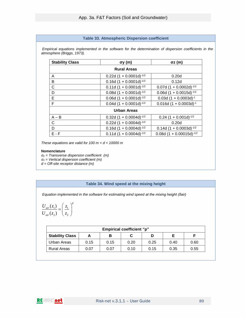
Risk-net v.3.1.1 – User Guide
App. 3a. F&T Factors (Soil and Groundwater)
89
Table 33. Atmospheric Dispersion coefficient
Empirical equations implemented in the software for the determination of dispersion coefficients in the atmosphere (Briggs, 1973).
Stability Class σy (m) σz (m)
Rural Areas
A 0.22d (1 + 0.0001d)-1/2 0.20d
B 0.16d (1 + 0.0001d)-1/2 0.12d
C 0.11d (1 + 0.0001d)-1/2 0.07d (1 + 0.0002d)-1/2
D 0.08d (1 + 0.0001d)-1/2 0.06d (1 + 0.0015d)-1/2
E 0.06d (1 + 0.0001d)-1/2 0.03d (1 + 0.0003d)-1
F 0.04d (1 + 0.0001d)-1/2 0.016d (1 + 0.0003d)-1
Urban Areas
A – B 0.32d (1 + 0.0004d)-1/2 0.24 (1 + 0.001d)-1/2
C 0.22d (1 + 0.0004d)-1/2 0.20d
D 0.16d (1 + 0.0004d)-1/2 0.14d (1 + 0.0003d)-1/2
E - F 0.11d (1 + 0.0004d)-1/2 0.08d (1 + 0.00015d)-1/2
These equations are valid for 100 m < d < 10000 m Nomenclature σy = Transverse dispersion coefficient (m) σz = Vertical dispersion coefficient (m) d = Off-site receptor distance (m)
Table 34. Wind speed at the mixing height
Equation implemented in the software for estimating wind speed at the mixing height (δair)
1 1
2 2
( )
( )
p
air
air
U z z
U z z
Empirical coefficient “p”
Stability Class A B C D E F
Urban Areas 0.15 0.15 0.20 0.25 0.40 0.60
Rural Areas 0.07 0.07 0.10 0.15 0.35 0.55

Risk-net v.3.1.1 – User Guide
App. 3a. F&T Factors (Soil and Groundwater)
90
Table 35. Subsurface Soil: Outdoor vapor volatilization
3
( )
3
3
(1) 10
( ) 1'
/min
/'
(2) 10 (optional)
ssamb Vol
air air s SP
w s s a eff
s
airsamb
soil
s ssamb
air air outdoor
HVF BDF
U LK H
D Wmg m
VFmg kg
W dVF
U
Nomenclature ds= Thickness of subsurface soil source (cm) Ls (SP) = Depth to subsurface soil source (cm) Ds
eff = Effective diffusivity in the vadose zone (cm2/s) W' = Width of source area parallel to wind direction (cm) δair = Ambient air mixing zone height (cm) Uair = Wind speed(cm/s) τoutdoor = Averaging time for vapor flux (s) θw = Volumetric water content in the vadose zone (-) θa = Volumetric air content in the vadose zone (-) θe = Effective porosity in the vadose zone (-) H = Henry’s law constant (-) ρs = Soil bulk density (g/cm3) BDFVol = Biodegradation factor (-)

Risk-net v.3.1.1 – User Guide
App. 3a. F&T Factors (Soil and Groundwater)
91
Table 36. Subsurface Soil: Indoor vapor volatilization
3
3
(1)/
min(2) 10 (optional)/
sesp
airsesp s s
sespsoil
b indoor
VFmg m
VF dVFmg kg
L ER
No differential outdoor/indoor pressure (Δp=0)
( ) 3
( ) ( )
( )(1) 10
1
eff
s s
w s s a s SP crack b
sesp Voleff eff
s s crack
eff
s SP crack b crack s SP crack
H D
K H L Z L ERVF BDF
D D L
L Z L ER D L Z
Differential outdoor/indoor pressure (Δp≠0)
( ) 3
( ) ( )
( )(1) 10
1
eff
s s
w s s a s SP crack b
sesp Voleff eff
s s b
s SP crack b s s SP crack
H De
K H L Z L ERVF BDF
D D Ae e
L Z L ER Q L Z
Convective Air Flow Through Foundation Cracks, Qs (cm3/s)
2
2ln
v crack s cracks eff
crack bcrack crackair
b
p k X Q LQ
D AZ X
A
Nomenclature Lcrack = Thickness foundations (cm) Lb = Enclosed space volume/infiltration area ratio (cm) Zcrack = Depth to base of enclosed space foundation (cm) ds = Thickness of subsurface soil source (cm) Ls (SP) = Depth to subsurface soil source (cm) Ds
eff = Effective diffusivity in the vadose zone (cm2/s) Dcrack
eff = Effective diffusivity in the foundations (cm2/s) τindoor = Averaging time for vapor flux (s) ER = Enclosed-space air exchange rate (1/s) η = Areal fraction of cracks in foundations/walls (-) θw = Volumetric water content in the vadose zone (-) θa = Volumetric air content in the vadose zone (-) θe = Effective porosity in the vadose zone (-) H = Henry’s law constant (-) ρs = Soil bulk density (g/cm3) Xcrack = Enclosed space foundation perimeter (cm) Δp = Differential indoor/outdoor air pressure (g/cm2/s) kv = Soil vapor permeability (cm2) Ab = Area of building foundation (cm2) μair = Vapor Viscosity (g/cm/s) BDFVol = Biodegradation factor (-)

Risk-net v.3.1.1 – User Guide
App. 3a. F&T Factors (Soil and Groundwater)
92
Table 37. Subsurface Soil: Leaching Factor
(1)/
min/ (2) (optional)
wssp LF
watsp
s ssoilsp
eff LF
K SAMLF BDF
LDFmg LLF
dmg kg LFI
Soil Attenuation model, SAM (-)
(optional)
s
gw s SP
dSAM
L L
Dilution Factor, LDF (-)
1gw gw
eff
vLDF
I W
Partition Coefficient (kg/L)
inorganics
organics
dsws s
oc ocw s s a
KK K
K fK H
Groundwater mixing zone thickness, δgw (cm)
2 0,5(2 0.0056 ) 1 exp for
eff
gw a gw a gw a
gw a
W IW d d d
v d
Infiltration Rate
2
eff outdoorI P
Sandy Soils (Sand, Loamy Sand and SandyLoam) β =0.0018; SIlty Soils (Sandy Clay Loam, Loam, Silt Loam and Silt) β =0.0009; Clay Soils (Clay Loam, Silty Clay Loam, Silty Clay, Sandy Clay and Clay) β =0.00018.
Nomenclature ds = Thickness of subsurface soil source (cm) Lgw = Depth to groundwater (cm) Ls (SP) = Depth to subsurface soil source (cm) vgw= Groundwater Darcy velocity (cm/s) Ksat= Hydraulic Conductivity (cm/s) Ieff = Infiltration Rate (cm/s) τLF = Averaging time for leachate flux (s) θw = Volumetric water content in the vadose zone (-) θa = Volumetric air content in the vadose zone (-) θe = Effective porosity in the vadose zone (-) H = Henry’s law constant (-) ρs = Soil bulk density (g/cm3) foc = Organic Carbon Fraction (-) da = Groundwater Thickness (cm) W = Width of source area parallel to groundwater flow direction (cm) αz = Vertical Dispersivity (cm)
BDFLF = Biodegradation factor (-)

Risk-net v.3.1.1 – User Guide
App. 3a. F&T Factors (Soil and Groundwater)
93
Table 38. Groundwater Attenuation Factor
DAF1 (-)
41exp 1 1
1 2 4 4
gwx w
x e y z
R Sxerf erf
DAF v x x
DAF2 (-)
41exp 1 1
2 2 4 2
gwx w
x e y z
R Sxerf erf
DAF v x x
DAF3(-)
41exp 1 1
3 2 4
x w
x e y
R Sxerf
DAF v x
Effective groundwater velocity, ve (cm/s) Constituent retardation factor, R (-)
,
sate
e sat
K iv
,
1 ss
e sat
R K
Longitudinal Dispersivity, αx (cm)
10x POC
Transversal Dispersivity, αy (cm)
3y x
Vertical Dispersivity, αz (cm)
20z x
Nomenclature λ = First-order degradation rate (1/s) Sw = Width of source area orthogonal to groundwater flow (cm) δgw = Groundwater mixing zone thickness (cm) x = distance(cm) Ks = Soil-water sorption coefficient (mg/kg/mg/L) θe,sat = Effective porosity, saturated zone (-) ρs = Soil bulk density (g/cm3) i = Hydraulic gradient (-) Ksat = Hydraulic conductivity(cm/s) POC = Distance to groundwater receptor (cm)

Risk-net v.3.1.1 – User Guide
App. 3a. F&T Factors (Soil and Groundwater)
94
Table 39. Groundwater: Indoor Vapors Volatilization
No differential outdoor/indoor pressure (Δp=0)
3/ 310/
1
eff
w
gw crack bairwesp Voleff eff
w w crackwater
eff
gw crack b crack gw crack
DH
L Z L ERmg mVF BDF
D D Lmg L
L Z L ER D L Z
Differential outdoor/indoor pressure (Δp=0)
3/ 310/
( 1)
eff
w
gw crack bairwesp Voleff eff
w w bwater
gw crack b s gw crack
DH e
L Z L ERmg mVF BDF
D D Amg Le e
L Z L ER Q L Z
Convective Air Flow Through Foundation Cracks, Qs (cm3/s)
2
2ln
v crack s cracks eff
crack bcrack crackair
b
p k X Q LQ
D AZ X
A
Nomenclature Lcrack = Thickness foundations (cm) Lb = Enclosed space volume/infiltration area ratio (cm) Zcrack = Depth to base of enclosed space foundation (cm) Lgw = Depth to groundwater (cm) Dw
eff = Effective diffusivity from groundwater (cm2/s) Dcrack
eff = Effective diffusivity in the foundations (cm2/s) τindoor = Averaging time for vapor flux (s) ER = Enclosed-space air exchange rate (1/s) η = Areal fraction of cracks in foundations/walls (-) θw = Volumetric water content in the vadose zone (-) θa = Volumetric air content in the vadose zone (-) θe = Effective porosity in the vadose zone (-) H = Henry’s law constant (-) ρs = Soil bulk density (g/cm3) Xcrack = Enclosed space foundation perimeter (cm) Δp = Differential indoor/outdoor air pressure (g/cm2/s) kv = Soil vapor permeability (cm2) Ab = Area of building foundation (cm2) μair = Vapor Viscosity (g/cm/s)
BDFVol = Biodegradation factor (-)

Risk-net v.3.1.1 – User Guide
App. 3a. F&T Factors (Soil and Groundwater)
95
Table 40. Groundwater: Outdoor Vapors Volatilization
33/
10/
1'
airwamb Vol
air air gwwat
eff
w
mg m HVF BDF
U Lmg L
D W
Nomenclature Lgw= Depth to Groundwater cm) Dw
eff= Effective diffusivity from groundwater (cm2/s) W' = Width of source area parallel to wind direction (cm) δair = Ambient air mixing zone height (cm) Uair = Wind speed(cm/s) H = Henry’s law constant (-) BDFVol = Biodegradation factor (-)

Risk-net v.3.1.1 – User Guide
App. 3a. F&T Factors (Soil and Groundwater)
96
Table 41. Diffusion Coefficient
Diffusion Coefficient in the vadose zone
3,33 3,332
2 2
eff a a w ws
e e
D DcmD
s H
Diffusion Coefficient in the capillary fringe
3,33 3,332
2 2
, ,
a acap w wcapeff
cap
e cap e cap
D DcmD
s H
Diffusion Coefficient in the clay lens
2 3,33 3,33
2 2
, ,
eff a alens w wlenslente
e lens e lens
cm D DD
s H
Diffusion Coefficient in the foundations
3,33 3,332
2 2
, ,
eff a acrack w wcrackcrack
e crack e crack
D DcmD
s H
Diffusion Coefficient from groundwater
2cap veff
wcap v
eff eff
cap s
h hcmD
h hs
D D
Diffusion Coefficient in the presence of a clay lens 2
eff ss lente
s lens lens
eff eff
suolo lente
cm LD
L d ds
D D
Nomenclature hcap = Capillary fringe thickness (cm) hv = Vadose zone thickness (cm) dlens = Thickness of the lens (cm) Da = Diffusion coefficient in air (cm2/s) Dw = Diffusion coefficient in water (cm2/s) θw = Volumetric water content in the vadose zone (-) θa = Volumetric air content in the vadose zone (-) θwcap = Volumetric water content in the capillary fringe (-) θacap = Volumetric air content in the capillary fringe (-) θwlens = Volumetric water content in the lens (-) θalens = Volumetric air content in the lens (-) θwcrack = Volumetric water content in the foundations (-) θacrack = Volumetric air content in the foundations (-) θe = Effective Porosity in the vadose zone (-) θe,cap = Effective Porosity in the capillary fringe (-) θe,crack = Effective Porosity in the foundations (-) H = Henry’s law constant (-) ρs = Soil bulk density (g/cm3)

Risk-net v.3.1.1 – User Guide
App. 3a. F&T Factors (Soil and Groundwater)
97
Table 42. Saturation Concentration (Csat )
Saturation Concentration
/ w a s ssat
s
H KC mg kg S
Nomenclature θw = Volumetric water content in the vadose zone (-) θa = Volumetric air content in the vadose zone (-) S = Solubility (mg/L) H = Henry’s law constant (-) ρs = Soil bulk density (g/cm3)

Risk-net v.3.1.1 – User Guide
App. 3a. F&T Factors (Soil and Groundwater)
98
Table 43. Biodegradation factor (BDF) per the volatilization pathway
Biodegradation factor (optional) is valid only for Ls >0 (Source: Verginelli and Baciocchi, 2014) Outdoor volatilization
exp( )2
1
aVol
s a
kLBDF
k L L con
w
eff
s
kH D
Nomenclature
Ls = Depth of the source (cm) * La = Depth of the aerobic zone (cm) Ds
eff = Effective diffusivity in the vadose zone (cm2/s) θw = Volumetric water content in the vadose zone (-) H = Henry’s law constant (-) λ = First-order biodegradation constant (1/s) Biodegradation factor (optional) is valid only for Ls –Zcrack >0 (Source: Verginelli and Baciocchi, 2014)
Outdoor volatilization
,
,
exp( )2
1
a indoor
Vol
s crack a indoor
kLBDF
k L Z L with
w
eff
s
kH D
Nomenclature Ls = Depth of the source (cm) * Ds
eff = Effective diffusivity in the vadose zone (cm2/s) θw = Volumetric water content in the vadose zone (-) H = Henry’s law constant (-) Zcrack = Depth to the base of enclosed space foundation (cm) La,indoor = Depth of the aerobic zone from building foundations (cm) λ = First-order biodegradation constant (1/s)
* For soil-gas data Ls is the depth of the probe
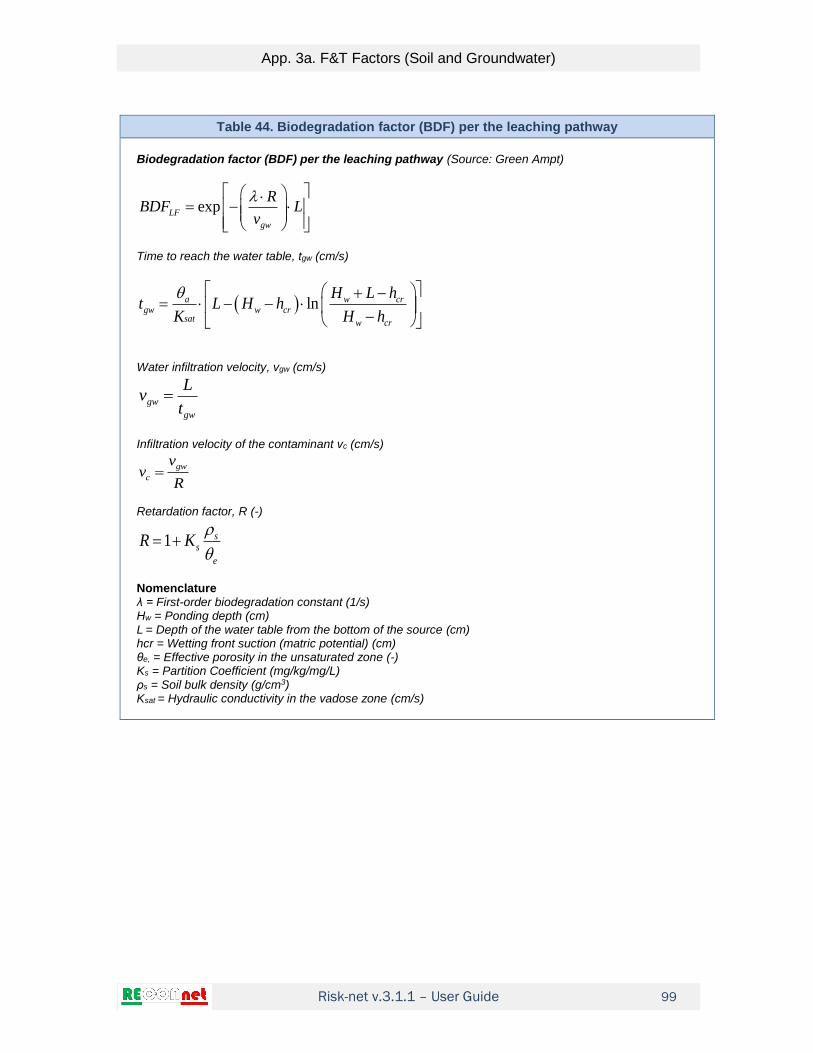
Risk-net v.3.1.1 – User Guide
App. 3a. F&T Factors (Soil and Groundwater)
99
Table 44. Biodegradation factor (BDF) per the leaching pathway
Biodegradation factor (BDF) per the leaching pathway (Source: Green Ampt)
exp
LF
gw
RBDF L
v
Time to reach the water table, tgw (cm/s)
ln
a w crgw w cr
sat w cr
H L ht L H h
K H h
Water infiltration velocity, vgw (cm/s)
gw
gw
Lv
t
Infiltration velocity of the contaminant vc (cm/s)
gw
c
vv
R
Retardation factor, R (-)
1
s
s
e
R K
Nomenclature λ = First-order biodegradation constant (1/s) Hw = Ponding depth (cm) L = Depth of the water table from the bottom of the source (cm) hcr = Wetting front suction (matric potential) (cm) θe, = Effective porosity in the unsaturated zone (-) Ks = Partition Coefficient (mg/kg/mg/L) ρs = Soil bulk density (g/cm3) Ksat = Hydraulic conductivity in the vadose zone (cm/s)

Risk-net v.3.1.1 – User Guide
App. 3a. F&T Factors (Soil and Groundwater)
100
Table 45. Infiltration Rate
Infiltration Rate
2
eff outdoorI P
Sandy Soils (Sand, Loamy Sand and SandyLoam) β =0.0018; SIlty Soils (Sandy Clay Loam, Loam, Silt Loam and Silt) β =0.0009; Clay Soils (Clay Loam, Silty Clay Loam, Silty Clay, Sandy Clay and Clay) β =0.00018. Effective infiltration in the presence of a low permeability layer between the source and the water table (ISPRA, 2005)
eff unsat fI K i
Vertical hydraulic gradient
perc unsat
f
unsat
h di
d
Effective infiltration in the presence of a HDPE sheet (ISPRA, 2005)
’ ’ ’ eff m fm f ff s fsI L L L
where:
’ 0.9 0.1 0.74
’ 0.9 0.1 0.74
’ 0.9 0.1 0.74
cracks
holes
patches
fm d av perc m eq
ff d av perc f eq
fs d av perc s eq
L C i h a K
L C i h a K
L C i h a K
Vertical hydraulic gradient
0,95
1 0,1
perc
av
unsat
hi
d
Nomenclature
am, af, as: Cracks, holes and patches area in the HDPE sheet (cm2)
Cd: Empirical constant for the quality of the contact of the HDPE sheet (-)
dunsat: Thickness of the low-permeability layer (below the HDPE sheet if present) (cm)
hperc: Hydraulic head above the HDPE sheet or the low-permeability layer (cm)
iav: Vertical hydraulic gradient (-)
Kunsat : Hydraulic conductivity of the low-permeability layer (below HDPE if present) (cm/y)
ρm, ρf, ρs: Cracks, holes and patches density in the HDPE sheet (#/cm2)
P = rainfall (cm/y)

Risk-net v.3.1.1 – User Guide
App. 3b. F&T Factors (Int. Characterization)
101
APP. 3B. F&T FACTORS (INT. CHARACTERIZATION)
The fate and transport factors considered in Risk-net for the integrative characterization
(i.e. soil-gas, flux chambers and leaching tests) are:
Soil-gas
αsamb: outdoor volatilization factor
αsesp: indoor volatilization factor
Flux chamber
αFC: outdoor volatilization factor (open flux chamber)
αFC(flux): outdoor volatilization factor (open and closed flux chamber)
Eluate
αLFss: leaching factor from surface soil
αLFsp: leaching factor from subsurface soil
The main assumptions on which are based the equations are:
- The concentration of pollutants in soil is uniformly distributed and constant throughout
the entire exposure period;
- Soil is homogeneous and isotropic and incoherent;
- No biodegradation (with the exception of DAF) or other mechanisms of degradation /
transformation of pollutants.
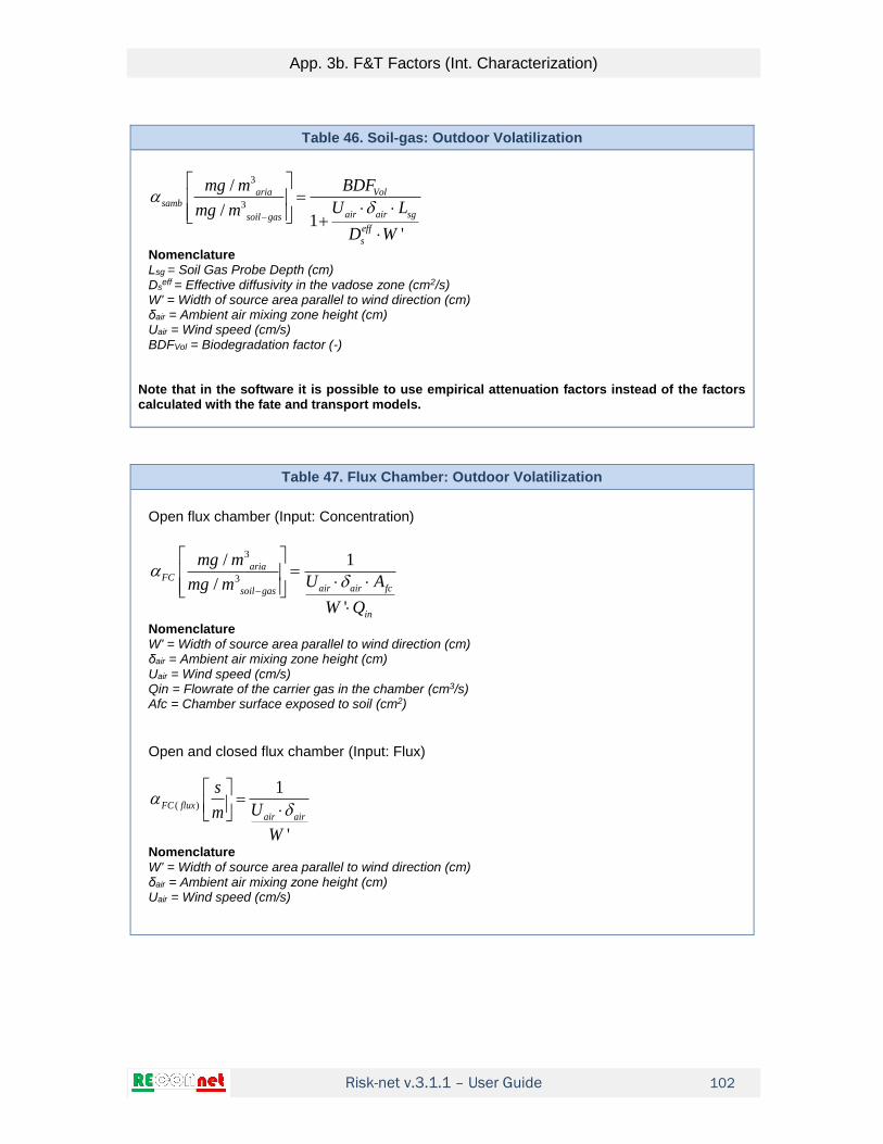
Risk-net v.3.1.1 – User Guide
App. 3b. F&T Factors (Int. Characterization)
102
Table 46. Soil-gas: Outdoor Volatilization
3
3
/
/1
'
aria Volsamb
air air sgsoil gas
eff
s
mg m BDF
U Lmg m
D W
Nomenclature Lsg = Soil Gas Probe Depth (cm) Ds
eff = Effective diffusivity in the vadose zone (cm2/s) W' = Width of source area parallel to wind direction (cm) δair = Ambient air mixing zone height (cm) Uair = Wind speed (cm/s) BDFVol = Biodegradation factor (-)
Note that in the software it is possible to use empirical attenuation factors instead of the factors calculated with the fate and transport models.
Table 47. Flux Chamber: Outdoor Volatilization
Open flux chamber (Input: Concentration)
3
3
/ 1
/
'
ariaFC
air air fcsoil gas
in
mg m
U Amg m
W Q
Nomenclature W' = Width of source area parallel to wind direction (cm) δair = Ambient air mixing zone height (cm) Uair = Wind speed (cm/s) Qin = Flowrate of the carrier gas in the chamber (cm3/s) Afc = Chamber surface exposed to soil (cm2)
Open and closed flux chamber (Input: Flux)
( )
1
'
FC fluxair air
s
Um
W Nomenclature
W' = Width of source area parallel to wind direction (cm) δair = Ambient air mixing zone height (cm) Uair = Wind speed (cm/s)

Risk-net v.3.1.1 – User Guide
App. 3b. F&T Factors (Int. Characterization)
103
Table 48. Soil-gas: Indoor Volatilization
No differential outdoor/indoor pressure (Δp=0)
3
3
/
/1
eff
s
sg crack bariasesp Voleff eff
s s cracksoil gas
eff
sg crack b crack sg crack
D
L Z L ERmg mBDF
D D Lmg m
L Z L ER D L Z
Differential outdoor/indoor pressure (Δp≠0)
3
3
/
/( 1)
eff
s
sg crack bariasesp Voleff eff
s s bsoil gas
sg crack b s sg crack
De
L Z L ERmg mBDF
D D Amg me e
L Z L ER Q L Z
Convective Air Flow Through Foundation Cracks, Qs (cm3/s)
2
2ln
v crack s cracks eff
crack bcrack crackair
b
p k X Q LQ
D AZ X
A
Nomenclature Lcrack = Thickness foundations (cm) Lb = Enclosed space volume/infiltration area ratio (cm) Zcrack = Depth to base of enclosed space foundation (cm) ds = Thickness of subsurface soil source (cm) Lsg = Soil Gas Probe Depth (cm) Ds
eff = Effective diffusivity in the vadose zone (cm2/s) Dcrack
eff = Effective diffusivity in the foundations (cm2/s) τindoor = Averaging time for vapor flux (s) ER = Enclosed-space air exchange rate (1/s) η = Areal fraction of cracks in foundations/walls (-) θw = Volumetric water content in the vadose zone (-) θa = Volumetric air content in the vadose zone (-) θe = Effective porosity in the vadose zone (-) H = Henry’s law constant (-) ρs = Soil bulk density (g/cm3) Xcrack = Enclosed space foundation perimeter (cm) Δp = Differential indoor/outdoor air pressure (g/cm2/s) kv = Soil vapor permeability (cm2) Ab = Area of building foundation (cm2) μair = Vapor Viscosity (g/cm/s) BDFVol = Biodegradation factor (-)
Note that in the software it is possible to use empirical attenuation factors instead of the factors calculated with the fate and transport models.

Risk-net v.3.1.1 – User Guide
App. 3b. F&T Factors (Int. Characterization)
104
Table 49. Flux Chamber: Indoor Volatilization
Open flux chamber (Input: Concentration)
3
, 3
/ 1
/
ariaFC indoor
b fcsoil gas
in
mg m
L ER Amg m
Q
Nomenclature
Lb = Enclosed space volume/infiltration area ratio (cm) ER = Enclosed-space air exchange rate (1/s) Qin = Flowrate of the carrier gas in the chamber (cm3/s) Afc = Chamber surface exposed to soil (cm2)
Open and closed flux chamber (Input: Flux)
( ),
1FC flux indoor
b
s
m L ER
Nomenclature Lb = Enclosed space volume/infiltration area ratio (cm) ER = Enclosed-space air exchange rate (1/s)

Risk-net v.3.1.1 – User Guide
App. 3b. F&T Factors (Int. Characterization)
105
Table 50. Eluate Surface Soil: Leaching to groundwater
/
/
acqua
LFss LF
eluato
mg L SAMBDF
mg L LDF Soil Attenuation model, SAM (-)
(optional)gw s SS
dSAM
L L
Leachate Dilution Factor, LDF (-)
1gw gw
eff
vLDF
I W
Groundwater mixing zone thickness, δgw (cm)
2 0,5(2 0.0056 ) 1 exp If eff
gw a gw a gw a
gw a
W IW d d d
v d
Nomenclature Lgw = Depth to groundwater (cm) d = Surface Soil Source Thickness (cm) Ls (SS) = Depth to surface soil source (cm) vgw= Groundwater Darcy velocity (cm/s) Ieff = Infiltration Rate (cm/s) da = Groundwater Thickness (cm) W = Width of source area parallel to groundwater flow direction (cm) αz = Vertical Dispersivity (cm) BDFLF = Biodegradation factor (-)

Risk-net v.3.1.1 – User Guide
App. 3b. F&T Factors (Int. Characterization)
106
Table 51. Eluate Subsurface Soil: Leaching to groundwater
/
/
acqua
LFsp LF
eluato
mg L SAMBDF
mg L LDF Soil Attenuation model, SAM (-)
(optional)gw s SP
dSAM
L L
Leachate Dilution Factor, LDF (-)
1gw gw
eff
vLDF
I W
Groundwater mixing zone thickness, δgw (cm)
2 0,5(2 0.0056 ) 1 exp If eff
gw a gw a gw a
gw a
W IW d d d
v d
Nomenclature Lgw = Depth to groundwater (cm) d = Subsurface Soil Source Thickness (cm) Ls (SP) = Depth to subsurface soil source (cm) vgw= Groundwater Darcy velocity (cm/s) Ieff = Infiltration Rate (cm/s) da = Groundwater Thickness (cm) W = Width of source area parallel to groundwater flow direction (cm) αz = Vertical Dispersivity (cm) BDFLF = Biodegradation factor (-)

Risk-net v.3.1.1 – User Guide
App. 4. Intake Rates
107
APP. 4. INTAKE RATES
The exposure factors are used to describe the expected behavior for the different
receptors within or near the site. Namely these models allow to calculate the average
ingested or inhaled dose over the lifetime of the receptor.
The exposure pathways considered in the software are:
Dermal contact with soil
Ingestion of soil
Inhalation of vapors in outdoor environments
Inhalation of vapors in indoor environments
Inhalation of particulate matter in outdoor environments
Inhalation of particulate matter in indoor environments
Inhalation of particulate matter in outdoor environments
Inhalation of particulate matter in indoor environments
Ingestion of water
The types of receptors considered are:
Residential or Recreational Scenario
a) Exposure Mediated (Child and Adult)
b) Exposure Mediated (Child, Teenager, adult and Senior)
c) Child
d) Adult
Commercial or Industrial Scenario
e) Adult Worker
For the residential or recreation exposure scenarios, the software can calculate an
average exposure value (options a and b) in order to adjust for varying body weights,
exposure durations, skin areas:
(option A)(canc.)
(option B)
child adult
adj
child teenager adult senior
EM EMEM
EM EM EM EM
(default)(non-canc.)
max( ; ; ; ) (if activated)
child
adj
child teenager adult senior
EMEM
EM EM EM EM
Similarly, exposure factors calculated using the "reference concentration method" (EC) in
the case of average exposure are equal to:
(option A)(canc.)
(option B)
child adult
adj
child teenager adult senior
EC ECEC
EC EC EC EC
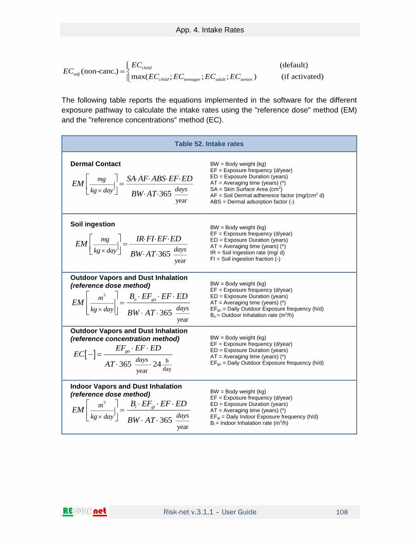
Risk-net v.3.1.1 – User Guide
App. 4. Intake Rates
108
(default)(non-canc.)
max( ; ; ; ) (if activated)
child
adj
child teenager adult senior
ECEC
EC EC EC EC
The following table reports the equations implemented in the software for the different
exposure pathway to calculate the intake rates using the "reference dose" method (EM)
and the "reference concentrations" method (EC).
Table 52. Intake rates
Dermal Contact
year365
mg
dayskg day
SA AF ABS EF EDEM
BW AT
BW = Body weight (kg) EF = Exposure frequency (d/year) ED = Exposure Duration (years) AT = Averaging time (years) (*) SA = Skin Surface Area (cm2) AF = Soil Dermal adherence factor (mg/(cm2 d) ABS = Dermal adsorption factor (-)
Soil ingestion
year365
mg
dayskg day
IR FI EF EDEM
BW AT
BW = Body weight (kg) EF = Exposure frequency (d/year) ED = Exposure Duration (years) AT = Averaging time (years) (*) IR = Soil Ingestion rate (mg/ d) FI = Soil ingestion fraction (-)
Outdoor Vapors and Dust Inhalation (reference dose method)
3
year365
o gom
dayskg day
B EF EF EDEM
BW AT
BW = Body weight (kg) EF = Exposure frequency (d/year) ED = Exposure Duration (years) AT = Averaging time (years) (*) EFgo = Daily Outdoor Exposure frequency (h/d) Bo = Outdoor Inhalation rate (m3/h)
Outdoor Vapors and Dust Inhalation (reference concentration method)
h
dayyear365 24
go
days
EF EF EDEC
AT
BW = Body weight (kg) EF = Exposure frequency (d/year) ED = Exposure Duration (years) AT = Averaging time (years) (*) EFgo = Daily Outdoor Exposure frequency (h/d)
Indoor Vapors and Dust Inhalation (reference dose method)
3
year365
i gim
dayskg day
B EF EF EDEM
BW AT
BW = Body weight (kg) EF = Exposure frequency (d/year) ED = Exposure Duration (years) AT = Averaging time (years) (*) EFgi = Daily Indoor Exposure frequency (h/d) Bi = Indoor Inhalation rate (m3/h)

Risk-net v.3.1.1 – User Guide
109
Table 52. Intake rates
Indoor Vapors and Dust Inhalation (reference dose method)
h
dayyear365 24
gi
days
EF EF EDEC
AT
EF = Exposure frequency (d/year) ED = Exposure Duration (years) AT = Averaging time (years) (*) EFgi = Daily Indoor Exposure frequency (h/d)
Water Ingestion (optional)
year365
wL
dayskg day
IR EF EDEM
BW AT
BW = Body weight (kg) EF = Exposure frequency (d/year) ED = Exposure Duration (years) AT = Averaging time (years) (*) IRw = Water Ingestion rate (L/d)
(*) For non-carcinogenic contaminants AT = ED

Risk-net v.3.1.1 – User Guide
App. 5. Using Advanced Characterization data
110
APP. 5. USING ADVANCED CHARACTERIZATION DATA
By default, in the software the data obtained in the advanced characterization of the site
(soil-gas, flux-chamber, air measurements and leaching tests) are exclusively used to
calculate the risks for the receptors. However, the user from the model options screen
("Advanced Characterization" screen) can decide whether to use these data also for the
modulation of SSTLs in the different environmental media (surface soil, subsurface soil
and groundwater). In this case, the data obtained from these monitoring campaigns are
used to calculate semi-empirical transport factors for the selected sources that are used
to calculate the new SSTLs.
The calculation of the empirical and semi-empirical transport factors are described in the
following sections.
Outdoor air measurements Outdoor air measurements can be used to estimate the site-specific attenuation of vapors observed in the field. In particular, by measuring the concentration in the air and the concentration in the source (soil or groundwater) it is possible to estimate the attenuation of the contaminants during transport from the source at the point of exposure. This factor, defined with the symbol β, can be estimated in the case of soil or groundwater using the following equations: Volatilization from soil
3,
( , )
/
/
air outdoor
soil AR Outdoor
soil
Cmg m
mg kg C
Volatilization from groundwater
3,
( , )
/
/
air outdoor
gw AR Outdoor
groundwater
Cmg m
mg L C
where: Cair,outdoor = Ambient Air Concentration (mg/m3) Csoil = Concentration in the soil (mg/kg) Cgroundwater = Concentration in groundwater (mg/L)
The β values can be calculated automatically by the software based on the concentrations defined in the source and in the outdoor air. Once the site-specific β factors have been estimated from the experimental data obtained from the monitoring campaigns, it is therefore possible to estimate the site-specific transport factors as described below.
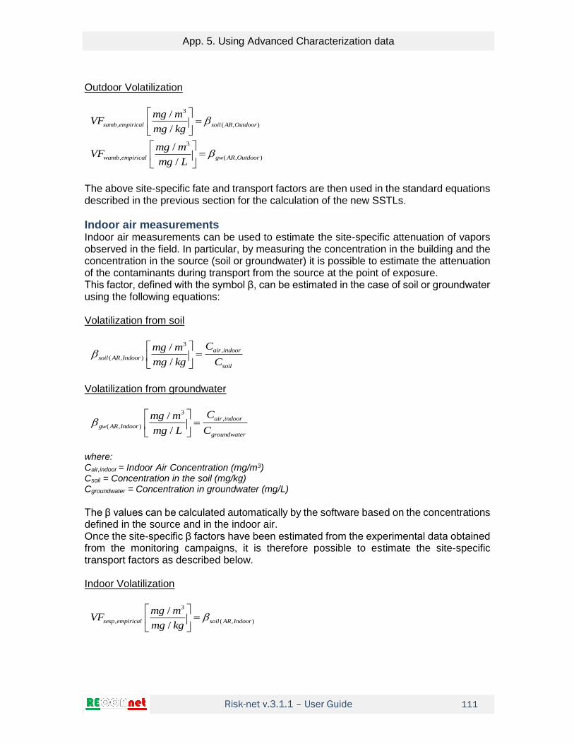
Risk-net v.3.1.1 – User Guide
App. 5. Using Advanced Characterization data
111
Outdoor Volatilization
3
, ( , )
/
/samb empirical soil AR Outdoor
mg mVF
mg kg
3
, ( , )
/
/wamb empirical gw AR Outdoor
mg mVF
mg L
The above site-specific fate and transport factors are then used in the standard equations described in the previous section for the calculation of the new SSTLs.
Indoor air measurements Indoor air measurements can be used to estimate the site-specific attenuation of vapors observed in the field. In particular, by measuring the concentration in the building and the concentration in the source (soil or groundwater) it is possible to estimate the attenuation of the contaminants during transport from the source at the point of exposure. This factor, defined with the symbol β, can be estimated in the case of soil or groundwater using the following equations: Volatilization from soil
3,
( , )
/
/
air indoor
soil AR Indoor
soil
Cmg m
mg kg C
Volatilization from groundwater
3,
( , )
/
/
air indoor
gw AR Indoor
groundwater
Cmg m
mg L C
where: Cair,indoor = Indoor Air Concentration (mg/m3) Csoil = Concentration in the soil (mg/kg) Cgroundwater = Concentration in groundwater (mg/L)
The β values can be calculated automatically by the software based on the concentrations defined in the source and in the indoor air. Once the site-specific β factors have been estimated from the experimental data obtained from the monitoring campaigns, it is therefore possible to estimate the site-specific transport factors as described below. Indoor Volatilization
3
, ( , )
/
/sesp empirical soil AR Indoor
mg mVF
mg kg

Risk-net v.3.1.1 – User Guide
App. 5. Using Advanced Characterization data
112
3
, ( , )
/
/wesp empirical gw AR Indoor
mg mVF
mg L
The above site-specific fate and transport factors are then used in the standard equations described in the previous section for the calculation of the new SSTLs.
Soil-gas measurements
Soil-gas measurements can be used to assess the site-specific attenuation of vapors
observed in the field. In particular, by measuring the concentration in the soil-gas and the
concentration in the source (soil or groundwater) it is possible to estimate the attenuation
of the contaminants during transport from the source at the soil-gas probe depth.
This factor, defined with the symbol β, can be estimated in the case of soil or groundwater using the following equations: Volatilization from soil
3
( )
/
/
soil gas
soil SG
soil
Cmg m
mg kg C
Volatilization from groundwater
3
( )
/
/
soil gas
fgw SG
groundwater
Cmg m
mg L C
where: Csoil-gas = Soil-gas Concentration (mg/m3) Csoil = Concentration in the soil (mg/kg) Cgroundwater = Concentration in groundwater (mg/L)
The β values can be calculated automatically by the software based on the concentrations defined in the source and in the soil gas. Once the site-specific β factors have been estimated from the experimental data obtained from the monitoring campaigns, it is therefore possible to estimate the site-specific transport factors as described below. Outdoor Volatilization
3
, ( )
/
/samb semi empirical soil SG samb
mg mVF
mg kg
3
, ( )
/
/wamb semi empirical gw SG samb
mg mVF
mg L

Risk-net v.3.1.1 – User Guide
App. 5. Using Advanced Characterization data
113
Indoor Volatilization
3
, ( )
/
/sesp semi empirical soil SG sesp
mg mVF
mg kg
3
, ( )
/
/wesp semi empirical gw SG sesp
mg mVF
mg L
The above site-specific fate and transport factors are then used in the standard equations described in the previous section for the calculation of the new SSTLs.
Flux Chambers measurements
Flux-chambers data can be used to assess the site-specific attenuation of vapors observed in the field. In particular, by measuring the concentration in the flux chamber and the concentration in the source (soil or groundwater), it is possible to estimate the attenuation of the contaminants during transport from the source to the ground surface. This factor, defined with the symbol β, can be estimated in the case of soil or groundwater using the following equations: Volatilization from soil (open chambers)
3
( )
/
/
FCsoil FC
soil
Cmg m
mg kg C
Volatilization from groundwater (open chambers)
3
( )
/
/
FCgw FC
groundwater
Cmg m
mg L C
where: CFC = Concentration in the flux chamber (mg/m3) Csoil = Concentration in the soil (mg/kg) Cgroundwater = Concentration in groundwater (mg/L)
Volatilization from soil (open and closed chambers)
2
( )
/
/soil FC flux
soil
mg m s F
mg kg C
Volatilization from groundwater (open and closed chambers)
2
( )
/
/gw FC flux
groundwater
mg m s F
mg L C
where:

Risk-net v.3.1.1 – User Guide
App. 5. Using Advanced Characterization data
114
F = Measured flux (mg/m2/s) Csoil = Concentration in the soil (mg/kg) Cgroundwater = Concentration in groundwater (mg/L)
The β values can be calculated automatically by the software based on the concentrations defined in the source and in the flux chambers. Once the site-specific β factors have been estimated from the experimental data obtained from the monitoring campaigns, it is therefore possible to estimate the site-specific transport factors as described below. Outdoor Volatilization (open chambers)
3
, ( )
/
/samb semi empirical soil FC FC
mg mVF
mg kg
3
, ( )
/
/wamb semi empirical fgw FC FC
mg mVF
mg L
Outdoor Volatilization (open and closed chambers)
3
, ( ) ( )
/
/samb semi empirical soil FC flux FC flux
mg mVF
mg kg
3
, ( ) ( )
/
/wamb semi empirical gw FC flux FC flux
mg mVF
mg L
The above site-specific fate and transport factors are then used in the standard equations described in the previous section for the calculation of the new SSTLs.
Leaching Tests
I risultati del test di cessione possono essere utilizzati per valutare la ripartizione sito-
specifica dei vapori osservata sul campo. In particolare, misurando la concentrazione
nell’eluato e la concentrazione in sorgente (localizzata nel terreno o nelle acque
sotterranee) è possibile la ripartizione tra il contaminante in sorgente e in fase disciolta
nell’acqua interstiziale.
The results of the leaching tests can be used to evaluate the site-specific partition of the
contaminants observed in the field. In particular, by measuring the concentration in the
eluate and the concentration in the source (soil or groundwater) it is possible to estimate
the partition between the contaminant in the source and in the dissolved phase in the
interstitial water.
This factor, defined with the symbol β, can be estimated in the case of soil or groundwater using the following equations:

Risk-net v.3.1.1 – User Guide
App. 5. Using Advanced Characterization data
115
Eluate – Surface Soil
,
( )
/
/
eluate ss
ss LF
ss
Cmg L
mg kg C
Eluate – Subsurface Soil
,
( )
/
/
eluato sp
sp LF
sp
Cmg L
mg kg C
where: Celuato,ss = Concentration in the eluate of the leaching test carried out on the surface soil (mg/L) Css = Concentration in surface soil (mg/kg) Celuato,sp = Concentration in the eluate of the leaching test carried out on the subsurface soil (mg/L) Csp = Concentration in subsurface soil (mg/kg)
The β values can be calculated automatically by the software based on the concentrations defined in the source and in the eluates. Once the site-specific β factors have been estimated from the experimental data obtained from the monitoring campaigns, it is therefore possible to estimate the site-specific transport factors as described below. Leaching from surface soil
, ( )
/
/ss semi empirical ss LF LFss
mg LLF
mg kg
Leaching from subsurface soil
, ( )
/
/sp semi empirical sp LF LFsp
mg LLF
mg kg
The above site-specific fate and transport factors are then used in the standard equations described in the previous section for the calculation of the new SSTLs.
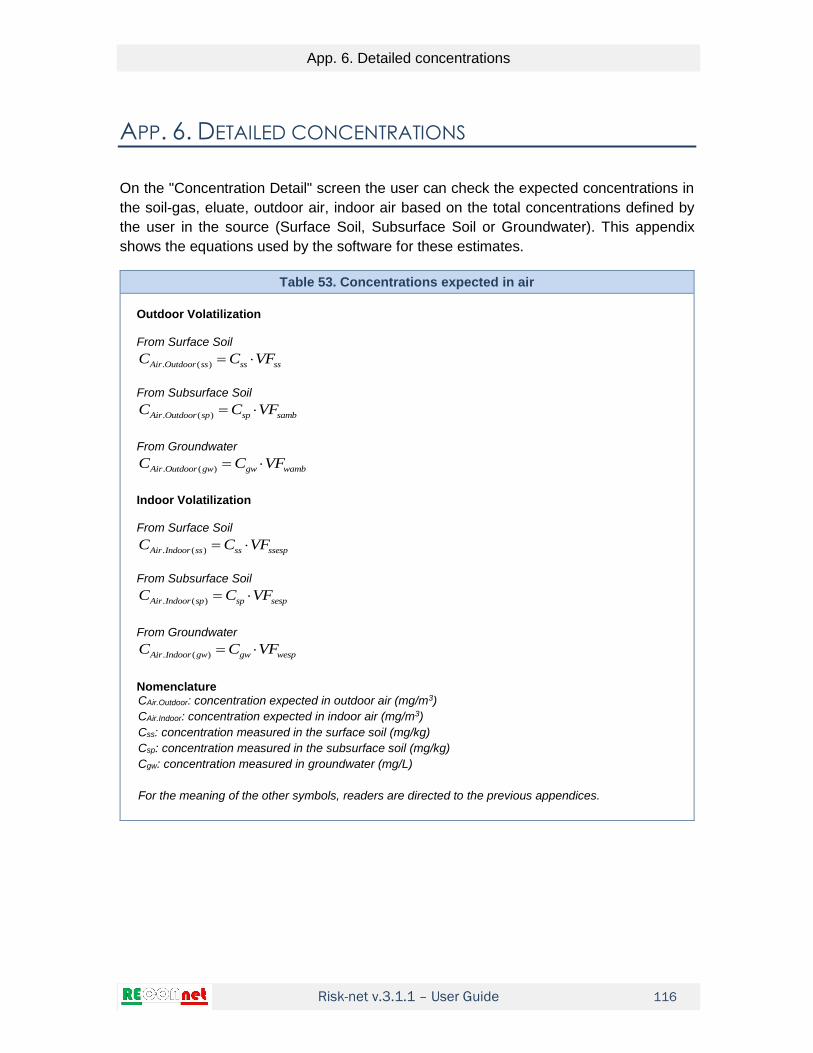
Risk-net v.3.1.1 – User Guide
App. 6. Detailed concentrations
116
APP. 6. DETAILED CONCENTRATIONS
On the "Concentration Detail" screen the user can check the expected concentrations in
the soil-gas, eluate, outdoor air, indoor air based on the total concentrations defined by
the user in the source (Surface Soil, Subsurface Soil or Groundwater). This appendix
shows the equations used by the software for these estimates.
Table 53. Concentrations expected in air
Outdoor Volatilization From Surface Soil
. ( )Air Outdoor ss ss ssC C VF
From Subsurface Soil
. ( )Air Outdoor sp sp sambC C VF
From Groundwater
. ( )Air Outdoor gw gw wambC C VF
Indoor Volatilization From Surface Soil
. ( )Air Indoor ss ss ssespC C VF
From Subsurface Soil
. ( )Air Indoor sp sp sespC C VF
From Groundwater
. ( )Air Indoor gw gw wespC C VF
Nomenclature CAir.Outdoor: concentration expected in outdoor air (mg/m3)
CAir.Indoor: concentration expected in indoor air (mg/m3)
Css: concentration measured in the surface soil (mg/kg)
Csp: concentration measured in the subsurface soil (mg/kg)
Cgw: concentration measured in groundwater (mg/L)
For the meaning of the other symbols, readers are directed to the previous appendices.
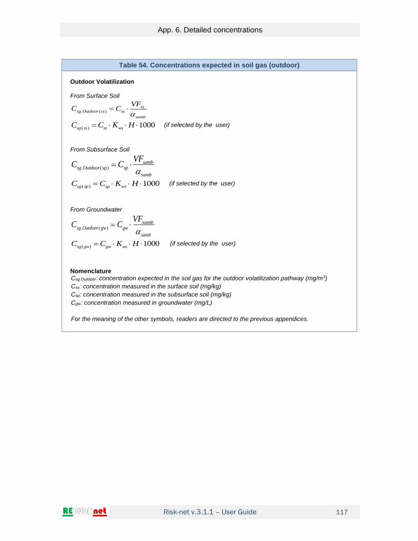
Risk-net v.3.1.1 – User Guide
App. 6. Detailed concentrations
117
Table 54. Concentrations expected in soil gas (outdoor)
Outdoor Volatilization From Surface Soil
. ( )
sssg Outdoor ss ss
samb
VFC C
( ) 1000 sg ss ss wsC C K H (if selected by the user)
From Subsurface Soil
. ( )
sambsg Outdoor sp sp
samb
VFC C
( ) 1000 sg sp sp wsC C K H (if selected by the user)
From Groundwater
. ( )
wambsg Outdoor gw gw
samb
VFC C
( ) 1000 sg gw gw wsC C K H (if selected by the user)
Nomenclature Csg.Outdoor: concentration expected in the soil gas for the outdoor volatilization pathway (mg/m3)
Css: concentration measured in the surface soil (mg/kg)
Csp: concentration measured in the subsurface soil (mg/kg)
Cgw: concentration measured in groundwater (mg/L)
For the meaning of the other symbols, readers are directed to the previous appendices.

Risk-net v.3.1.1 – User Guide
App. 6. Detailed concentrations
118
Table 55. Concentrations expected in soil gas (indoor)
Indoor Volatilization From Surface Soil
. ( )
ssesp
sg Indoor ss ss
sesp
VFC C
( ) 1000 sg ss ss wsC C K H (if selected by the user)
From Subsurface Soil
. ( )
sesp
sg Indoor sp sp
sesp
VFC C
( ) 1000 sg sp sp wsC C K H (if selected by the user)
From Groundwater
. ( )
wesp
sg Indoor gw gw
sesp
VFC C
( ) 1000 sg gw gw wsC C K H (if selected by the user)
Nomenclature Csg.Indoor: concentration expected in the soil gas for the indoor volatilization pathway (mg/m3)
Css: concentration measured in the surface soil (mg/kg)
Csp: concentration measured in the subsurface soil (mg/kg)
Cgw: concentration measured in groundwater (mg/L)
For the meaning of the other symbols, readers are directed to the previous appendices.

Risk-net v.3.1.1 – User Guide
App. 6. Detailed concentrations
119
Table 56. Concentrations expected in the flux chamber
Outdoor Volatilization From Surface Soil
( )
1000
ws
FC ss ss
FC
K HC C
From Subsurface Soil
( )
(1)
samb
FC sp sp
FC
VFC C
From Groundwater
( )
wambFC gw gw
FC
VFC C
Nomenclature Cfc: concentration expected in the flux chamber (mg/m3)
Css: concentration measured in the surface soil (mg/kg)
Csp: concentration measured in the subsurface soil (mg/kg)
Cgw: concentration measured in groundwater (mg/L)
For the meaning of the other symbols, readers are directed to the previous appendices.
Table 57. Concentration expected in the eluate
Leaching from the soil to groundwater From Surface Soil
( ) ( ) El ss ss ws ssC C K
From Subsurface Soil
( ) ( ) El sp sp ws spC C K
Nomenclature CEl: concentration expected in the the eluate (mg/L)
Css: concentration measured in the surface soil (mg/kg)
Csp: concentration measured in the subsurface soil (mg/kg)
For the meaning of the other symbols, readers are directed to the previous appendices.
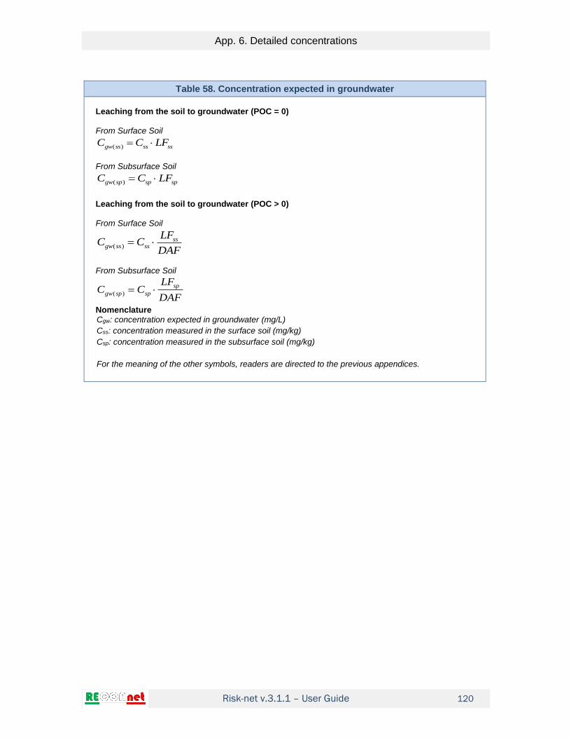
Risk-net v.3.1.1 – User Guide
App. 6. Detailed concentrations
120
Table 58. Concentration expected in groundwater
Leaching from the soil to groundwater (POC = 0) From Surface Soil
( ) gw ss ss ssC C LF
From Subsurface Soil
( ) gw sp sp spC C LF
Leaching from the soil to groundwater (POC > 0) From Surface Soil
( ) ssgw ss ss
LFC C
DAF
From Subsurface Soil
( ) sp
gw sp sp
LFC C
DAF
Nomenclature Cgw: concentration expected in groundwater (mg/L)
Css: concentration measured in the surface soil (mg/kg)
Csp: concentration measured in the subsurface soil (mg/kg)
For the meaning of the other symbols, readers are directed to the previous appendices.
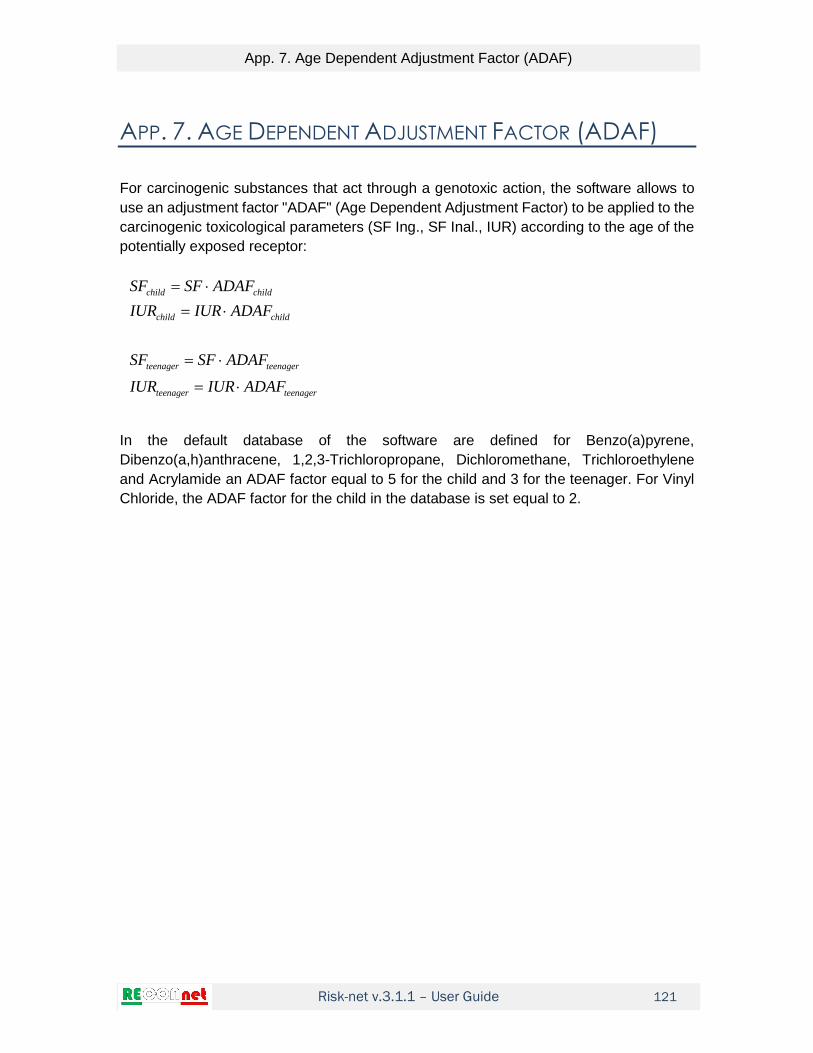
Risk-net v.3.1.1 – User Guide
App. 7. Age Dependent Adjustment Factor (ADAF)
121
APP. 7. AGE DEPENDENT ADJUSTMENT FACTOR (ADAF)
For carcinogenic substances that act through a genotoxic action, the software allows to
use an adjustment factor "ADAF" (Age Dependent Adjustment Factor) to be applied to the
carcinogenic toxicological parameters (SF Ing., SF Inal., IUR) according to the age of the
potentially exposed receptor:
child child
child child
teenager teenager
teenager teenager
SF SF ADAF
IUR IUR ADAF
SF SF ADAF
IUR IUR ADAF
In the default database of the software are defined for Benzo(a)pyrene,
Dibenzo(a,h)anthracene, 1,2,3-Trichloropropane, Dichloromethane, Trichloroethylene
and Acrylamide an ADAF factor equal to 5 for the child and 3 for the teenager. For Vinyl
Chloride, the ADAF factor for the child in the database is set equal to 2.

Risk-net v.3.1.1 – User Guide
App. 8. Koc and Kd function of pH
122
APP. 8. KOC AND KD FUNCTION OF PH
For the substances in which the Koc and the Kd are a function of the pH, if the Default
Database is used, the values of the distribution coefficients reported in the following tables
are adopted in the software according to the pH defined in the site.
Table 59. Koc values as a function of pH for some organic compounds (1/2).
Koc (L/kg) as a function of pH
pH Benzoic Acid 2-Chlorophenol Dichlorophenol (2,4) Dinitrophenol (2,4) Pentachlorophenol
4.9 5.5E+00 3.98E+02 1.59E+02 2.94E-02 9.05E+03
5 4.6E+00 3.98E+02 1.59E+02 2.55E-02 7.96E+03
5.1 3.9E+00 3.98E+02 1.59E+02 2.23E-02 6.93E+03
5.2 3.3E+00 3.98E+02 1.59E+02 1.98E-02 5.97E+03
5.3 2.7E+00 3.98E+02 1.59E+02 1.78E-02 5.10E+03
5.4 2.3E+00 3.98E+02 1.58E+02 1.62E-02 4.32E+03
5.5 1.9E+00 3.97E+02 1.58E+02 1.50E-02 3.65E+03
5.6 1.7E+00 3.97E+02 1.58E+02 1.40E-02 3.07E+03
5.7 1.4E+00 3.97E+02 1.58E+02 1.32E-02 2.58E+03
5.8 1.2E+00 3.97E+02 1.58E+02 1.25E-02 2.18E+03
5.9 1.1E+00 3.97E+02 1.57E+02 1.20E-02 1.84E+03
6 9.7E-01 3.96E+02 1.57E+02 1.16E-02 1.56E+03
6.1 8.8E-01 3.96E+02 1.57E+02 1.13E-02 1.33E+03
6.2 8.0E-01 3.96E+02 1.56E+02 1.10E-02 1.15E+03
6.3 7.4E-01 3.95E+02 1.55E+02 1.08E-02 9.98E+02
6.4 6.9E-01 3.94E+02 1.54E+02 1.06E-02 8.77E+02
6.5 6.5E-01 3.93E+02 1.53E+02 1.05E-02 7.81E+02
6.6 6.2E-01 3.92E+02 1.52E+02 1.04E-02 7.03E+02
6.7 6.0E-01 3.90E+02 1.50E+02 1.03E-02 6.40E+02
6.8 5.8E-01 3.88E+02 1.47E+02 1.02E-02 5.92E+02
6.9 5.6E-01 3.86E+02 1.45E+02 1.02E-02 5.52E+02
7 5.5E-01 3.83E+02 1.41E+02 1.02E-02 5.21E+02
7.1 5.4E-01 3.79E+02 1.38E+02 1.02E-02 4.96E+02
7.2 5.3E-01 3.75E+02 1.33E+02 1.01E-02 4.76E+02
7.3 5.3E-01 3.69E+02 1.28E+02 1.01E-02 4.61E+02
7.4 5.2E-01 3.62E+02 1.21E+02 1.01E-02 4.47E+02
7.5 5.2E-01 3.54E+02 1.14E+02 1.01E-02 4.37E+02
7.6 5.1E-01 3.44E+02 1.07E+02 1.01E-02 4.29E+02
7.7 5.1E-01 3.33E+02 9.84E+01 1.00E-02 4.23E+02
7.8 5.1E-01 3.19E+02 8.97E+01 1.00E-02 4.18E+02
7.9 5.1E-01 3.04E+02 8.07E+01 1.00E-02 4.14E+02
8 5.1E-01 2.86E+02 7.17E+01 1.00E-02 4.10E+02

Risk-net v.3.1.1 – User Guide
App. 8. Koc and Kd function of pH
123
Table 60. Koc values as a function of pH for some organic compounds (2/2).
Koc (L/kg) as a function of pH
pH Tetrachlorophenol
2,3,4,5 Tetrachlorophenol
2,4,6 Trichlorophenol
2,4,5 Trichlorophenol
2,4,6
4.9 1.73E+04 4.45E+03 2.37E+03 1.04E+03
5 1.72E+04 4.15E+03 2.36E+03 1.03E+03
5.1 1.70E+04 3.83E+03 2.36E+03 1.02E+03
5.2 1.67E+04 3.49E+03 2.35E+03 1.01E+03
5.3 1.65E+04 3.14E+03 2.34E+03 9.99E+02
5.4 1.61E+04 2.79E+03 2.33E+03 9.82E+02
5.5 1.57E+04 2.45E+03 2.32E+03 9.62E+02
5.6 1.52E+04 2.13E+03 2.31E+03 9.38E+02
5.7 1.47E+04 1.83E+03 2.29E+03 9.10E+02
5.8 1.40E+04 1.56E+03 2.27E+03 8.77E+02
5.9 1.32E+04 1.32E+03 2.24E+03 8.39E+02
6 1.24E+04 1.11E+03 2.21E+03 7.96E+02
6.1 1.15E+04 9.27E+02 2.17E+03 7.48E+02
6.2 1.05E+04 7.75E+02 2.12E+03 6.97E+02
6.3 9.51E+03 6.47E+02 2.06E+03 6.44E+02
6.4 8.48E+03 5.42E+02 1.99E+03 5.89E+02
6.5 7.47E+03 4.55E+02 1.91E+03 5.33E+02
6.6 6.49E+03 3.84E+02 1.82E+03 4.80E+02
6.7 5.58E+03 3.27E+02 1.71E+03 4.29E+02
6.8 4.74E+03 2.80E+02 1.60E+03 3.81E+02
6.9 3.99E+03 2.42E+02 1.47E+03 3.38E+02
7 3.33E+03 2.13E+02 1.34E+03 3.00E+02
7.1 2.76E+03 1.88E+02 1.21E+03 2.67E+02
7.2 2.28E+03 1.69E+02 1.07E+03 2.39E+02
7.3 1.87E+03 1.53E+02 9.43E+02 2.15E+02
7.4 1.53E+03 1.41E+02 8.19E+02 1.95E+02
7.5 1.25E+03 1.31E+02 7.03E+02 1.78E+02
7.6 1.02E+03 1.23E+02 5.99E+02 1.64E+02
7.7 8.31E+02 1.17E+02 5.07E+02 1.53E+02
7.8 6.79E+02 1.13E+02 4.26E+02 1.44E+02
7.9 5.56E+02 1.08E+02 3.57E+02 1.37E+02
8 4.58E+02 1.05E+02 2.98E+02 1.31E+02

Risk-net v.3.1.1 – User Guide
App. 8. Koc and Kd function of pH
124
Table 61. Kd values as a function of pH for some inorganic contaminants (1/2).
Kd (L/kg) as a function of pH
pH Arsenic Barium Beryllium Cadmium Chromium III Chromium VI
4.9 2.5E+01 1.1E+01 2.3E+01 1.5E+01 1.2E+03 3.1E+01
5 2.5E+01 1.2E+01 2.6E+01 1.7E+01 1.9E+03 3.1E+01
5.1 2.5E+01 1.4E+01 2.8E+01 1.9E+01 3.0E+03 3.0E+01
5.2 2.6E+01 1.5E+01 3.1E+01 2.1E+01 4.9E+03 2.9E+01
5.3 2.6E+01 1.7E+01 3.5E+01 2.3E+01 8.1E+03 2.8E+01
5.4 2.6E+01 1.9E+01 3.8E+01 2.5E+01 1.3E+04 2.7E+01
5.5 2.6E+01 2.1E+01 4.2E+01 2.7E+01 2.1E+04 2.7E+01
5.6 2.6E+01 2.2E+01 4.7E+01 2.9E+01 3.5E+04 2.6E+01
5.7 2.7E+01 2.4E+01 5.3E+01 3.1E+01 5.5E+04 2.5E+01
5.8 2.7E+01 2.6E+01 6.0E+01 3.3E+01 8.7E+04 2.5E+01
5.9 2.7E+01 2.8E+01 6.9E+01 3.5E+01 1.3E+05 2.4E+01
6 2.7E+01 3.0E+01 8.2E+01 3.7E+01 2.0E+05 2.3E+01
6.1 2.7E+01 3.1E+01 9.9E+01 4.0E+01 3.0E+05 2.3E+01
6.2 2.8E+01 3.3E+01 1.2E+02 4.2E+01 4.2E+05 2.2E+01
6.3 2.8E+01 3.5E+01 1.6E+02 4.4E+01 5.8E+05 2.2E+01
6.4 2.8E+01 3.6E+01 2.1E+02 4.8E+01 7.7E+05 2.1E+01
6.5 2.8E+01 3.7E+01 2.8E+02 5.2E+01 9.9E+05 2.0E+01
6.6 2.8E+01 3.9E+01 3.9E+02 5.7E+01 1.2E+06 2.0E+01
6.7 2.9E+01 4.0E+01 5.5E+02 6.4E+01 1.5E+06 1.9E+01
6.8 2.9E+01 4.1E+01 7.9E+02 7.5E+01 1.8E+06 1.9E+01
6.9 2.9E+01 4.2E+01 1.1E+03 9.1E+01 2.1E+06 1.8E+01
7 2.9E+01 4.2E+01 1.7E+03 1.1E+02 2.5E+06 1.8E+01
7.1 2.9E+01 4.3E+01 2.5E+03 1.5E+02 2.8E+06 1.7E+01
7.2 3.0E+01 4.4E+01 3.8E+03 2.0E+02 3.1E+06 1.7E+01
7.3 3.0E+01 4.4E+01 5.7E+03 2.8E+02 3.4E+06 1.6E+01
7.4 3.0E+01 4.5E+01 8.6E+03 4.0E+02 3.7E+06 1.6E+01
7.5 3.0E+01 4.6E+01 1.3E+04 5.9E+02 3.9E+06 1.6E+01
7.6 3.1E+01 4.6E+01 2.0E+04 8.7E+02 4.1E+06 1.5E+01
7.7 3.1E+01 4.7E+01 3.0E+04 1.3E+03 4.2E+06 1.5E+01
7.8 3.1E+01 4.9E+01 4.6E+04 1.9E+03 4.3E+06 1.4E+01
7.9 3.1E+01 5.0E+01 6.9E+04 2.9E+03 4.3E+06 1.4E+01
8 3.1E+01 5.2E+01 1.0E+05 4.3E+03 4.3E+06 1.4E+01

Risk-net v.3.1.1 – User Guide
App. 8. Koc and Kd function of pH
125
Table 62. Kd values as a function of pH for some inorganic contaminants (2/2).
Kd (L/kg) as a function of pH
pH Mercury Nickel Silver Selenium Thallium Zinc
4.9 4.0E-02 1.6E+01 1.0E-01 1.8E+01 4.4E+01 1.6E+01
5 6.0E-02 1.8E+01 1.3E-01 1.7E+01 4.5E+01 1.8E+01
5.1 9.0E-02 2.0E+01 1.6E-01 1.6E+01 4.6E+01 1.9E+01
5.2 1.4E-01 2.2E+01 2.1E-01 1.5E+01 4.7E+01 2.1E+01
5.3 2.0E-01 2.4E+01 2.6E-01 1.4E+01 4.8E+01 2.3E+01
5.4 3.0E-01 2.6E+01 3.3E-01 1.3E+01 5.0E+01 2.5E+01
5.5 4.6E-01 2.8E+01 4.2E-01 1.2E+01 5.1E+01 2.6E+01
5.6 6.9E-01 3.0E+01 5.3E-01 1.1E+01 5.2E+01 2.8E+01
5.7 1.0E+00 3.2E+01 6.7E-01 1.1E+01 5.4E+01 3.0E+01
5.8 1.6E+00 3.4E+01 8.4E-01 9.8E+00 5.5E+01 3.2E+01
5.9 2.3E+00 3.6E+01 1.1E+00 9.2E+00 5.6E+01 3.4E+01
6 3.5E+00 3.8E+01 1.3E+00 8.6E+00 5.8E+01 3.6E+01
6.1 5.1E+00 4.0E+01 1.7E+00 8.0E+00 5.9E+01 3.9E+01
6.2 7.5E+00 4.2E+01 2.1E+00 7.5E+00 6.1E+01 4.2E+01
6.3 1.1E+01 4.5E+01 2.7E+00 7.0E+00 6.2E+01 4.4E+01
6.4 1.6E+01 4.7E+01 3.4E+00 6.5E+00 6.4E+01 4.7E+01
6.5 2.2E+01 5.0E+01 4.2E+00 6.1E+00 6.6E+01 5.1E+01
6.6 3.0E+01 5.4E+01 5.3E+00 5.7E+00 6.7E+01 5.4E+01
6.7 4.0E+01 5.8E+01 6.6E+00 5.3E+00 6.9E+01 5.8E+01
6.8 5.2E+01 6.5E+01 8.3E+00 5.0E+00 7.1E+01 6.2E+01
6.9 6.6E+01 7.4E+01 1.0E+01 4.7E+00 7.3E+01 6.8E+01
7 8.2E+01 8.8E+01 1.3E+01 4.3E+00 7.4E+01 7.5E+01
7.1 9.9E+01 1.1E+02 1.6E+01 4.1E+00 7.6E+01 8.3E+01
7.2 1.2E+02 1.4E+02 2.0E+01 3.8E+00 7.8E+01 9.5E+01
7.3 1.3E+02 1.8E+02 2.5E+01 3.5E+00 8.0E+01 1.1E+02
7.4 1.5E+02 2.5E+02 3.1E+01 3.3E+00 8.2E+01 1.3E+02
7.5 1.6E+02 3.5E+02 3.9E+01 3.1E+00 8.5E+01 1.6E+02
7.6 1.7E+02 4.9E+02 4.8E+01 2.9E+00 8.7E+01 1.9E+02
7.7 1.8E+02 7.0E+02 5.9E+01 2.7E+00 8.9E+01 2.4E+02
7.8 1.9E+02 9.9E+02 7.3E+01 2.5E+00 9.1E+01 3.1E+02
7.9 1.9E+02 1.4E+03 8.9E+01 2.4E+00 9.4E+01 4.0E+02
8 2.0E+02 1.9E+03 1.1E+02 2.2E+00 9.6E+01 5.3E+02