risk management center strong ® project description original dam constructed 1896, reconstructed in...
TRANSCRIPT

US Army Corps of EngineersBUILDING STRONG®
Risk Management Center
Kevin S. Richards, Ph.D., P.E.Institute for Water ResourcesRisk Management Center
2013 Shlemon Specialty ConferenceDam Foundations Failures and Incidents
Thursday, May 16, 13

BUILDING STRONG®
Outline
Introduction/Geologic Setting 2002 Dam Safety Modification Foundation Conditions Fuse Plug Activation Design Considerations Lessons Learned Conclusions
2Thursday, May 16, 13

BUILDING STRONG®
Introduction/Geologic Setting
3Thursday, May 16, 13

BUILDING STRONG®
Upper Peninsula Michigan
4
•Silver Lake provides headwater storage for the Dead River•Project is located 14 miles northwest of Ishpeming, MI
Thursday, May 16, 13

BUILDING STRONG®
Dead River Basin
5
Topography is dominated by large glacial outwash plains and low, rolling hills or ridges of Precambrian, meta-igneous bedrocks (schist and gneiss) and metamorphic bedrocks (slate and chert).
Thursday, May 16, 13

BUILDING STRONG®
Geologic Setting
6
Marquette Range Supergroup (founded on Archean)•Baraga (deeper marine/collision)
•Michigamme Slate•Menominee (foredeep basin)
•Ajibik Quartzite•Siamo Slate
•Chocolay (shallow-marine)•Mesnard Quartzite•Kona Dolomite•Wewe Slate
Deposition of the supergroup continued until 1.85 b.y. ago, when the Penokean Orogeny began
Thursday, May 16, 13

BUILDING STRONG®
Bedrock Geology
7
XMmls – Michigamme Formation-slate (Paleo-proterozoic)WMmb – Mona Formation-basalt (Neo-archean)WMgg – Granite and granitic gneiss (Archean)WMgn – Gneiss
Penokean Fold and Thrust Belt
Thursday, May 16, 13
Mona Formation is Neoarchean age. The lower part of the Mona is famous for its pillow basalt lavas well exposed in road cuts.The Marquette Range Supergroup was deformed and metamorphosed about 1.9 b.y. ago.

BUILDING STRONG®
Glacial Sediments
8Thursday, May 16, 13

BUILDING STRONG®
Project Description Original dam constructed 1896, reconstructed in 1912, modified in
1944 (raised 8-ft), modified in 2002 (fuse plug spillway) Provides headwater benefits for 4 downstream hydropower plants Statistics
► Normal maximum pool elevation 1482.5 ft (prior to installation of fuse plug in accordance with FERC License)
► Normal maximum pool elevation 1481.5 ft (as estimated during design of the fuse plug)
► PMF peak pool elevation 1488.75 (22,050 cfs)1
► 1500-ft long, 30-ft high main earthen embankment (crest 1491.5 ft)► Four detached saddle dikes (3- crests at 1491.5 ft, 1- crest at 1487.7)► 15-ft long concrete low level outlet structure (max. capacity 280 cfs, is used to
pass 20 cfs minimum flow during normal operation)
9
120,760 cfs through fuse plug and 1,290 cfs through overflow spillway, 0 cfs thorough low level outlet
Thursday, May 16, 13

BUILDING STRONG®
Project Instrumentation
Staff gage (site is over 10 miles from nearest town, on dirt roads, in a remote, undeveloped area, and there are no utilities at the site)
Dam operators visit the site about once per week, with less frequent visits during winter months due to poor condition of roads
10Thursday, May 16, 13

BUILDING STRONG®11
April 28, 1998 (Before Breach)
August 28, 2005 (After Breach)
Breached May 14, 2003
Modified August 2002 – October 2002
Dike No. 2
Low Level Outlet
Overflow Spillway
1
2
3
1
2
3
Reconstructed 2008
Thursday, May 16, 13

BUILDING STRONG®
2002 Dam Safety Modification
12Thursday, May 16, 13

BUILDING STRONG®
Background Project was not originally equipped to pass the PMF (original 1994
estimated PMF outflow was 18,598 cfs but overtopping capacity was only 545 cfs)
Fuse plug concept was proposed and accepted August 2001 Revised PMF routing completed September 2001
► PMF peak pool elevation 1488.75 (with emergency fuse plug spillway in-place)
► Assumed normal maximum operating pool for initial conditions► Requires regrading saddle dikes to an elevation of 1491.5
Design Report completed March 2002 Plans and specifications accepted/construction contract awarded
13Thursday, May 16, 13

BUILDING STRONG®
Emergency Fuse Plug & Dam Safety Modifications
Convert Dike No. 2 into a fuse plug spillway► 5.5 foot high fuse plug (foundation at 1481.0 ft)► grass-lined exit channel
Regrade existing dikes (1, 3 and 4) Construct saddle dike at the Main Dam Install new toe drains and manholes Repair concrete damage at the outlet and spillway
14Thursday, May 16, 13

BUILDING STRONG®
Proposed Modifications
15Thursday, May 16, 13

BUILDING STRONG®
Fuse Plug
16Thursday, May 16, 13

BUILDING STRONG®
Fuse Plug Materials
17Thursday, May 16, 13

BUILDING STRONG®
Fuse Plug Channel
18
Area with no treatment
Area with grass treatment
Thursday, May 16, 13

BUILDING STRONG®19
Thursday, May 16, 13

BUILDING STRONG®
Original Design
20
Original design called for an 8-foot deep rock trench
Thursday, May 16, 13

BUILDING STRONG®
Modifications to Main Dam
21Thursday, May 16, 13

BUILDING STRONG®
Foundation Conditions
22Thursday, May 16, 13

BUILDING STRONG®
Landforms
23Thursday, May 16, 13

BUILDING STRONG®
Bedrock Geology
24Thursday, May 16, 13

BUILDING STRONG®
Soils
25
Keewaydin Series – very deep, well drained soils on bedrock-controlled moraines. Formed in loamy and silty eolian deposits overlying gravelly and sandy till. Gravelly – bouldery in places.
Thursday, May 16, 13

BUILDING STRONG®
Foundation Soils
26
a. "Coarse-textured glacial till.“ 90% fine to coarse sand and 10% non-plastic fines (SP-SM), with occasional gravel, cobbles and boulders. View is of left channel downstream of former fuse plug.
b. Upper horizon is oxidized and contains some roots from surface vegetation. Stands vertically similar to loess. Contains weak cementation. View is of left channel downstream of former fuse plug.
a.
b.
c.
c. The upper SP-SM unit appears to contain a weak soil structure (weak carbonate cementation?) that when disturbed loses strength and crumbles (pile at arrow). This unit has a lowdry strength and is easily broken by light finger pressure. View is of left channel downstream of former fuse plug.
Rills?
Tunnel?
Thursday, May 16, 13

BUILDING STRONG®
Vadose-zone Tunneling
27
a. Note the dark brown unit immediately below circular erosional features. This unit is a fine to medium clean sand (SP), is moist to wet, and contains prominent thin bedding (locally cross-bedded). View is of left channel downstream of former fuse plug.
b. View of similar erosional features as described previous photo. Note the association of a vertical fracture with two of these erosional pockets. View is of an “island” remnant downstream of former fuse plug.
a. b.
Tunneling was attributed to solution of the silt and/or carbonate content of the coarse-textured glacial till
TunnelVadose Zone
Phreatic Zone
Thursday, May 16, 13

BUILDING STRONG®
Foundation Characteristics1
The foundation observed in the side walls of the breach includes 3 stratum;► (1) tan, loose to medium dense sand from the ground surface to an approximate
depth of 8-10 feet. This stratum contains some outwash material, but is primarily weathered till.
► (2) tan, very dense, cemented, weathered till approximately 10 feet thick, ► (3) dark gray, very dense, cemented unweathered till.
The grain size distribution of all till layers appeared to be a slightly silty coarse to fine sand with some gravel, with the most noticeable difference in stratums being the tan coloration of the upper two weathered zones, and the lower density of the uppermost zone. The till was in general void of clayey or plastic fines.
When samples of either the dense tan weathered or gray unweathered till were placed in water, they quickly melted into a cohesionless mass (dispersive soil?).
Sand cone dry density varied from 114.3 lbs/ft3 immediately under the fuse plug (Stratum 2), and 127.5 lbs/ft3 near the bottom of Stratum 3
Sand cone dry density for the material on the “floor” of the breach was 134.8 lbs/ft3
28
1FERC description of breach area
Thursday, May 16, 13

BUILDING STRONG®
Other Observations Top 10 feet of till described as weathered, but is weakly cemented From borings, the foundation can divided into three strata (each
strata varies laterally);► Top unit (SP to SM) with little gravel in the top 8 to 10 feet
(outwash, aeolian, and weathered till?) ► Middle unit (SM), weakly stratified where gravel content increases
from 10 to 18 feet (reworked/weathered ground moraine?)► Lower unit (SM), silty sand with non-plastic clay, where cobbles
and fines content increase with depth from 18 to 26 feet (unweathered ground moraine?)
► Bedrock is more than 75-feet beneath the surface
29Thursday, May 16, 13

BUILDING STRONG®
Key Points (cont.)
Silt, Gravel, and Cobble percentages increase with depth with up to 26% cobbles and 23% gravel in lower unit (Ground Moraine?)
“Floor” of breach area was composed of a very well cemented conglomeratic, silty-clayey cobble material.
Tunneling features were observed near the phreatic zone in the upper till, and crumb sample exhibited dispersive characteristics
30Thursday, May 16, 13

BUILDING STRONG®
Class Discussion
What do you think about this plan?
31Thursday, May 16, 13

BUILDING STRONG®
Fuse Plug Activation
32Thursday, May 16, 13

BUILDING STRONG®
May 7, 2003
Early snowmelt, practically no snow left on frozen ground Lake level was observed to be 1483.35 on May 7, 2003
(normal maximum pool elevation, after installation of fuse plug is 1481.5)
33Thursday, May 16, 13

BUILDING STRONG®
May 9-11
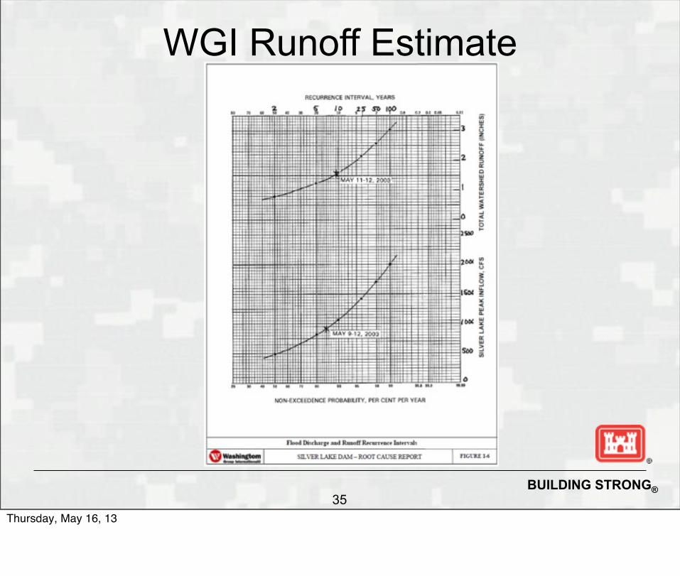
“Mother’s Day Storm” occurred from May 9-12 ICRP estimated 4.5 inches of rain fell during May 8-12,
with about 4.1 inches concentrated on May 10-11 (the 100-yr 24h precipitation was reported to be about 4.3 inches)
WGI estimated 4 inches of precipitation fell, which resulted in a 10-year runoff event
34Thursday, May 16, 13
BUILDING STRONG®
WGI Runoff Estimate
35Thursday, May 16, 13

BUILDING STRONG®
May 12-13
Pool began to rise from inflows from the recent rainfall and antecedent condition
Spillway stoplogs remained in-place throughout the runoff event
36Thursday, May 16, 13

BUILDING STRONG®
Estimated Inflow Hydrographs
37Thursday, May 16, 13

BUILDING STRONG®
May 14-15 Fuse plug began to trigger when the pool elevation
exceeded the lower of the two pilot channels (1485.28) Pool eventually rose to ~1485.60 ft (fuse plug crest at
1486.5 ft, concrete spillway crest at 1486.25) Muddy water was observed 2.5 miles downstream from
Silver Lake at about 3:00 PM on May 14, 2003 Erosion did not stop at the fuse plug foundation elevation
of 1481.0, but continued 28 feet into the foundation to an elevation of 1453.0 feet at its lowest point.
Resulting peak breach outflow was estimated to be
38Thursday, May 16, 13

BUILDING STRONG®
7 PM May 14, 2003
39
A headcut was observed progressing into the reservoir
Thursday, May 16, 13

BUILDING STRONG®
Breach Topography
40
The breach excavated 28-feet into the foundation beneath the fuse plug.
Thursday, May 16, 13

BUILDING STRONG®41
Peak water elevation was measured from a mark at the stoplog section of the spillway.
Thursday, May 16, 13

BUILDING STRONG®
Fuse-plug Channel
42
a. Foreground shows the original ground surface of the fuse plug channel, looking downstream. Flood erosion occurred to the right of the line marked by the arrow. Note the coarse-grained cobble and boulder deposition along the channel centerline. View is on left channel downstream of former fuse plug.
b. View of channel erosion and flood deposition downstream of former fuse plug. Note the light-colored deposits in the upper right of the photograph (arrow). This shows large amounts of well graded sand that were deposited as a point-bar at an inner bend of the channel alignment, approximately 1,100 feet downstream of the former fuse plug.
a. b.
A stable thalweg developed as a result of the breach, erosion, and deposition of cobbles and boulders on the stream bed. Note the high amount of erosion along the channel banks that extends over 1000-feet downstream. Also note lack of vegetation on the prepared channel area.
Thursday, May 16, 13

BUILDING STRONG®
Class Discussion
What issues have you identified? What’s the root cause for this failure?
43Thursday, May 16, 13

BUILDING STRONG®
Post-Event Findings
44Thursday, May 16, 13

BUILDING STRONG®
Independent Consultant Review Panel
45
Report No. 2FERC Independent Consultant’s Review Panel
Silver Lake Dam
Technical Reasons for the Release (December 2003)
Alfred J. Hendron Jr.Nelson PintoJ. Michael Duncan
Thursday, May 16, 13

BUILDING STRONG®
Filter Requirements
46
Fuse plug zones did not all meet filter requirements. However, the ICRP found that internal erosion of the core into the filter was highly unlikely because this interface met filter criteria. Similarly, erosion of the foundation into the filter downstream of the core was also ruled-out.
Thursday, May 16, 13

BUILDING STRONG®
SPT
47
SPT blow counts were high (note- blow counts do not always correlate with erodibility)
Thursday, May 16, 13

BUILDING STRONG®
Reservoir Operations
Before 1988, reservoir levels prior to snow melt ranged from 1464.0 to 1475.0, this provided ample storage for snow melt and spring rain
After 1988, when ownership of the project changed and the project was undergoing relicensing, the MDNR and USFWS added requirements for minimum flow and required the reservoir be operated within a small range between 1477.0 in December and 1481.5 in July
Raising the minimum level from 1467.5 to 1477.0 reduced reservoir storage by about 10,000 acre-ft
48Thursday, May 16, 13

BUILDING STRONG®
ICRP Findings Cannot rule-out internal erosion, but the fact that breach occurred
when reservoir levels were peaking, and evidence confirms reservoir exceeded the pilot channel invert elevations, failure by overtopping is most likely failure mode.
If the bottom outlet valve were opened on April 23 to discharge 280 cfs, consistent with the concept of the new normal maximum operation level restriction, it would have prevented the incident.
The erodibility of the fuse plug foundation and the emergency spillway channel is the root cause of the Silver Lake reservoir release.
The reservoir would not be released, except for the upper 5 feet, for any activation of the fuse plug if the fuse plug had been founded on a
49Thursday, May 16, 13

BUILDING STRONG®
ICRP Findings (cont.)
Probability of activation of the fuse plug was higher than the probability of overtopping Dike 4 prior to the modification (<1 ft versus 2.1 ft of freeboard)
Allowable velocity for the fine sand at the exit channel at Silver Lake is 1.5 fps, and for fine gravel is 2.5 fps. It is clear channel velocities exceeded the 2.5 fps limit for no grass cover on cohesionless sands
Although the rock structure may have slowed the erosion, it is most likely it would have been undermined due to its shallow depth (8 ft)
50Thursday, May 16, 13

BUILDING STRONG®
ICRP Findings (cont.)
The erodibility of the fuse plug foundation and emergency spillway channel is the root cause of the Silver Lake Reservoir releases… for any normal release of the fuse plug, except for the upper 5 ft, the amount of discharge would have been limited if the fuse plug were founded on a non-erodible foundation in a non-erodible channel.
51Thursday, May 16, 13

BUILDING STRONG®
Design Considerations
52Thursday, May 16, 13

BUILDING STRONG®
Design Issues
Designer was under the impression that due to regulatory requirements, the owner would maintain the pool below 1481.5 ft
Owner wasn’t aware of this change and continued to operate the reservoir as it had historically been operated
Design called for permanent removal of the stoplogs. This action was removed from the contract and the stoplogs remained in-place throughout the event
Elevation of the control section in the channel containing the fuse plug should not be lower than the top of active conservation capacity elevation1
53
1 (USBR, Technical Memorandum No. 10 – Guidelines for using fuse plug embankments in auxiliary spillways)
Thursday, May 16, 13

BUILDING STRONG®
Design Issues
Fuse plugs should not activate at <100-year flood► Main dam and saddle dikes should have been raised so the fuse
plug pilot channel elevation could be raised above the 500-year pool elevation, without human intervention, and the main spillway could remain in-service to handle frequent floods
► To save cost and avoid raising the main dam and saddle dikes, changes to reservoir operations to avoid activating the fuse plug during high-frequency events, were required; but, due to the remote location of the dam, ingrained operations, and lack of understanding by the owner, these changes to operations were never implemented
► Fuse plug pilot channels were therefore designed to trigger before the main ogee spillway would activate, in effect decommissioning the main spillway
54Thursday, May 16, 13

BUILDING STRONG®
Design Issues (cont.) The foundation for fuse plugs should be non-erodible
materials Due to short growing season, grass had not been
established yet when the fuse plug was activated Original plan was to provide erosion protection with a
grass-lined channel, but exit channel velocities were estimated to have been as high as 14.5 fps, on an unvegetated sand foundation, and should not have exceeded 1.5 fps
Exit channel thalweg downstream of spillways should be
55Thursday, May 16, 13

BUILDING STRONG®
Design Issues (cont.)
The fuse-plug design depended on pulling stoplogs when the pool exceeded a certain level; however, the site is remote and not instrumented, and is only visited once per week or less. Also, there were no rain gaging stations installed to monitor precipitation levels
While changes to operating procedures were discussed in the design documentation, there was poor coordination/communication between design engineers and operations staff
56Thursday, May 16, 13

BUILDING STRONG®
Design Issues (cont.)
Rock trench was eliminated during construction, but rock trench was probably not an effective design
Removal of stoplogs was taken out of the contract, for unknown reasons
Reservoir was allowed to refill without grass being established in fuse plug channel (although grass was ineffective erosion protection)
Project was designed without full understanding of foundation conditions in area of fuse plug
Design of exit channel did not adequately address hydraulics of downstream channel and headcutting potential
57Thursday, May 16, 13

BUILDING STRONG®
Lessons Learned
58
Important for operations personnel to provide input during evaluation of alternatives, especially if changes to operations are proposed
Design engineers must be kept abreast of changes being made during construction, especially when they involve not doing modifications to control works
Carefully consider making changes to reservoir operations in lieu of structural modifications, particularly at remote projects where human intervention may not be practical
Thursday, May 16, 13

BUILDING STRONG®
Lessons Learned (cont.)
Tunneling in the left abutment may have eventually led to breach of the fuse plug by internal erosion, even if activation by overtopping had not occurred
When operational changes are required during design of a dam modification, a revised reservoir operating plan should be submitted with the plans and specifications for owner review, prior to award of a construction contract
59Thursday, May 16, 13

BUILDING STRONG®
Questions?
60
Silver Lake Dike No. 2 restored in 2008
Thursday, May 16, 13