risk assessment -...
TRANSCRIPT
RISK ASSESSMENT
This Risk Assessment (RA) study includes a description of the process, screening of
dangerous goods, a qualitative assessment and where required, subsequent quantitative
risk assessment.
The primary objectives of a Risk Assessment study are to:
• Identify potential hazards associated with the manufacturing activities
• Analyse the consequences of significant hazards on people and the environment,
and the likelihood or frequency of these hazards occurring
• Estimate the resultant risk to the surrounding land uses and environment and
• Analyse the safeguards to ensure they are adequate, and therefore demonstrate
that the operation can operate within acceptable risk levels to its surroundings
1 Hazard Identification
1.1 Hazardous Materials
Sl. No. Raw Materials
1. Clinkers
2. Gypsum
3. Fly Ash
4. HSD (DG Set)
1.2 Hazardous Event Identification Word Diagram
In accordance with the requirements of Guidelines for Hazard Analysis, (Ref 1), it is
necessary to identify hazardous events which could be caused by the proposed operations.
As recommended in HIPAP 6, this study focuses on “a typical and abnormal events and
conditions. It is not intended to apply to continuous or normal operating emissions to air or
water”. The latter are discussed elsewhere in the environmental assessment.
In keeping with the principles of preliminary hazard analyses or similar, credible, hazardous
events with the potential for off-site effects have been identified. That is, “slips, trips and
falls” type events or events that can be readily contained on-site are not included. Similarly,
non-credible situations such as an aircraft crash occurring at the same time as an
earthquake are not included.
The credible, significant incidents identified are summarized in the Hazard Identification
Word Diagram following. The diagram presents the causes and consequences of the events,
together with major preventative and protective features that are included as part of the
design. The identified events apply to the modified facility, i.e. they include existing
potential hazardous events with off-site impact as well as new potential hazardous events as
a result of the proposed changes.
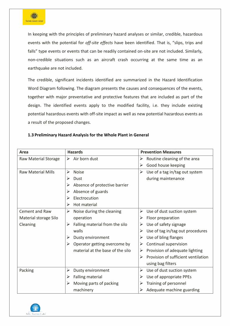
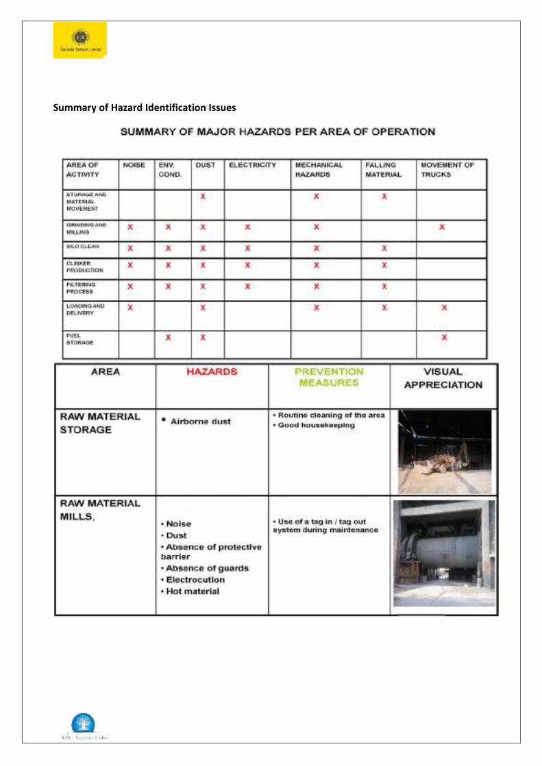
1.3 Preliminary Hazard Analysis for the Whole Plant in General
Area Hazards Prevention Measures Raw Material Storage Air born dust Routine cleaning of the area
Good house keepingRaw Material Mills Noise
Dust Absence of protective barrier Absence of guards Electrocution Hot material
Use of a tag in/tag out systemduring maintenance
Cement and Raw Material storage Silo Cleaning
Noise during the cleaningoperation
Falling material from the silowalls
Dusty environment Operator getting overcome by
material at the base of the silo
Use of dust suction system Floor preparation Use of safety signage Use of tag in/tag out procedures Use of bling flanges Continual supervision Provision of adequate lighting Provision of sufficient ventilation
using bag filtersPacking Dusty environment
Falling material Moving parts of packing
machinery
Use of dust suction system Use of appropriate PPEs Training of personnel Adequate machine guarding
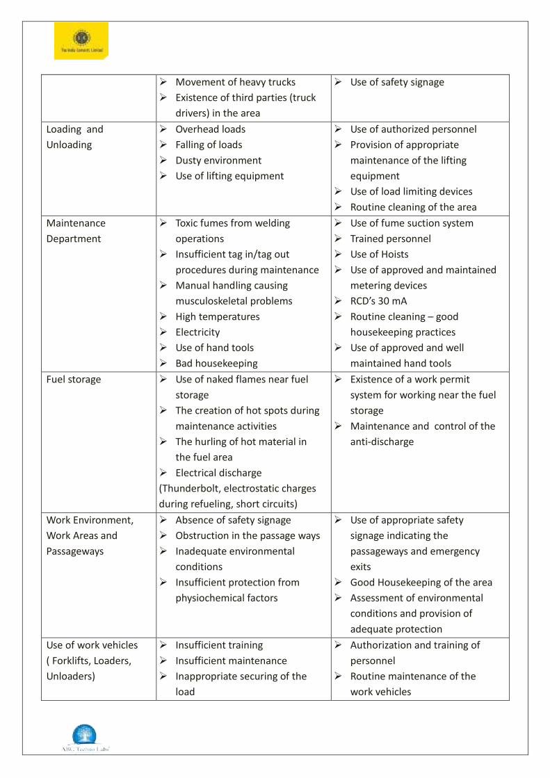
Movement of heavy trucks Existence of third parties (truck
drivers) in the area
Use of safety signage
Loading and Unloading
Overhead loads Falling of loads Dusty environment Use of lifting equipment
Use of authorized personnel Provision of appropriate
maintenance of the liftingequipment
Use of load limiting devices Routine cleaning of the area
Maintenance Department
Toxic fumes from weldingoperations
Insufficient tag in/tag outprocedures during maintenance
Manual handling causingmusculoskeletal problems
High temperatures Electricity Use of hand tools Bad housekeeping
Use of fume suction system Trained personnel Use of Hoists Use of approved and maintained
metering devices RCD’s 30 mA Routine cleaning – good
housekeeping practices Use of approved and well
maintained hand toolsFuel storage Use of naked flames near fuel
storage The creation of hot spots during
maintenance activities The hurling of hot material in
the fuel area Electrical discharge(Thunderbolt, electrostatic charges during refueling, short circuits)
Existence of a work permitsystem for working near the fuelstorage
Maintenance and control of theanti-discharge
Work Environment, Work Areas and Passageways
Absence of safety signage Obstruction in the passage ways Inadequate environmental
conditions Insufficient protection from
physiochemical factors
Use of appropriate safetysignage indicating thepassageways and emergencyexits
Good Housekeeping of the area Assessment of environmental
conditions and provision ofadequate protection
Use of work vehicles ( Forklifts, Loaders, Unloaders)
Insufficient training Insufficient maintenance Inappropriate securing of the
load
Authorization and training ofpersonnel
Routine maintenance of thework vehicles

Speeding Insufficient visibility
Provision of work instructions Labelling of the vehicle
movement area
2 Safety Management Systems
Safety management systems are intended to minimize the risk from potentially hazardous
installations by a combination of hardware (i.e. design) and software factors (managements
systems such as safeguards, procedures, policies, plans, training etc). To ensure safe
operation of the processing plants, storage and transfer systems, both the hardware and the
software systems must be of high standard.
2.1 Hazards connected with HSD
Diesel is the only flammable material stored in the facility in storage yard with small
quantity under completely covered roof. Since the quantity is very small there will not be
any occurrences of catastrophic failure and big fires.
Possible fire is pool fire result of damages of 200 litres of barrel.
1. HSD – Pool Fire
Consequence analysis is impossible for this small quantity.
2.2 Maximum Credible Accident and Consequence Analysis
Maximum Credible Accident and Consequence Analysis (MCACA) is one of the
methodologies evolved to quantify releases of hazardous chemicals. A Maximum Credible
Accident can be described as the worst “credible” accident or as an accident with a
maximum damage distance, which is still believed to be probable. The selection of
Maximum Credible Accidents is somewhat arbitrary. In practice the selection of accident
scenarios is done on the basis of engineering judgment and expertise in the field of risk
analysis especially in accident analysis.
The MCACA aims at identifying undesirable and hazardous events causing the maximum
damage to human beings and environment in and around the industries under
consideration. This exercise is not only important to reduce the risks of existing units in
industrial area, but also to provide valuable information for the location of future units for
which there is little or only limited operating experience available.
The following steps are followed in the MCACA.
i. Preparation of an inventory of major chemical storages and rank them on the
basis of their hazardous properties and storage quantities.
ii. Identification of potential hazardous areas and representative failure cases
from the vessels and pipes.
iii. Visualization of the chemical release scenarios.
iv. Short-listing of maximum credible accident scenarios.
v. Effect and damage calculations from the release cases through mathematical
modelling.
Note: Since, there will not be bulk storages of flammable, Toxic, corrosive and reactive
material in the facility, there will not be the possibilities of occurrences of catastrophic
failures such as fire, toxic dispersion etc.
2.3 Recommendations
Diesel storage shall be in dyke walls.
Operating personnel should be thorough with all aspects of operation, Safety
Systems, Fire Fighting etc. their reaction time should be monitored.
Mentioned control measures in the hazard identification word diagram should be
implemented.
Silos storage pressure level shall be maintained as per specification.
All engineering equipment’s shall be properly maintained and operating persons are
properly trained.
Applicable personnel protective equipment’s shall be provided and used by all the
workers in the facility.
Safety training such as Fire drill, Evacuation Mock Drill, first aid training shall be given
to identified workers.
3 DISASTER MANAGEMENT PLAN
3.1 Introduction
Emergency is a general term implying the onset of hazardous situation both inside and
outside the installation. Thus, Emergencies are termed “On-Site” when it is confined within
the plant even though it may require external help and “Off-Site” when emergency extends
beyond the plant boundaries to public area. It is to be understood here, that if an
emergency occurs inside the plant and could not be controlled, it may lead to an Off-Site
Emergency.
Emergency planning is an important part of loss prevention strategy. The type of emergency
primarily considered here is the major emergency which may be defined as one which has
the potential to cause serious danger to persons and or damage to property and which
tends to cause disruption inside and or outside the site and may require the use of outside
resources.
3.2 Objectives of the plan
Emergency Planning and Preparedness is a Comprehensive Response Plan to react to a
number of predictable emergencies anticipated in the works and to contain the loss of
human life, property and provide speedy and effective remedial measures. Important pre-
requisite for emergency planning is to forecast an accident scenario which leads to a major
fire, explosion, toxic gas release, their spread or extent and their damage potential. This
information is used in conjunction with layout of the units in the works, and adjacent
communities in the preparation of the contingency plan.
Identification of scenarios and their consequences form important elements in the
emergency planning. The type of scenarios and their consequences determine the
emergency response. Identification of scenarios and mitigation include the detection of
abnormal conditions, assessing the potential consequences and immediate measures to
mitigate the situations. This includes emergency response action which must be taken to
protect the health and the safety of the plant personnel and the public.
Assuming all reasonable plant safety design and their improvements have been considered
like design codes & practices, alarms, shutdown interlocks etc., the accidents may still occur
as the plant operating parameters and their values may exceed or lie outside the normal
parameters.
These uncontrollable parameters give the plant operators an indication of consequences in
advance of actual occurrence. The important elements of Emergency Planning can be
broadly classified as follows:
i. Identifying the disaster potential scenarios and advance planning to combat and
minimize the damage.
ii. Disaster phase i.e. warning, protective action like evacuation of personnel etc.
iii. Containment of disaster by isolating, fire fighting etc.
iv. Rescue, relief assistance to the people affected in the works / community
effectively and efficiently based on the actual needs and on the information
collected locally both in advance of the disaster and as soon as possible after the
disaster occurred.
v. Finally when the situation is contained, efforts are to be taken to return back to
near- normal conditions.
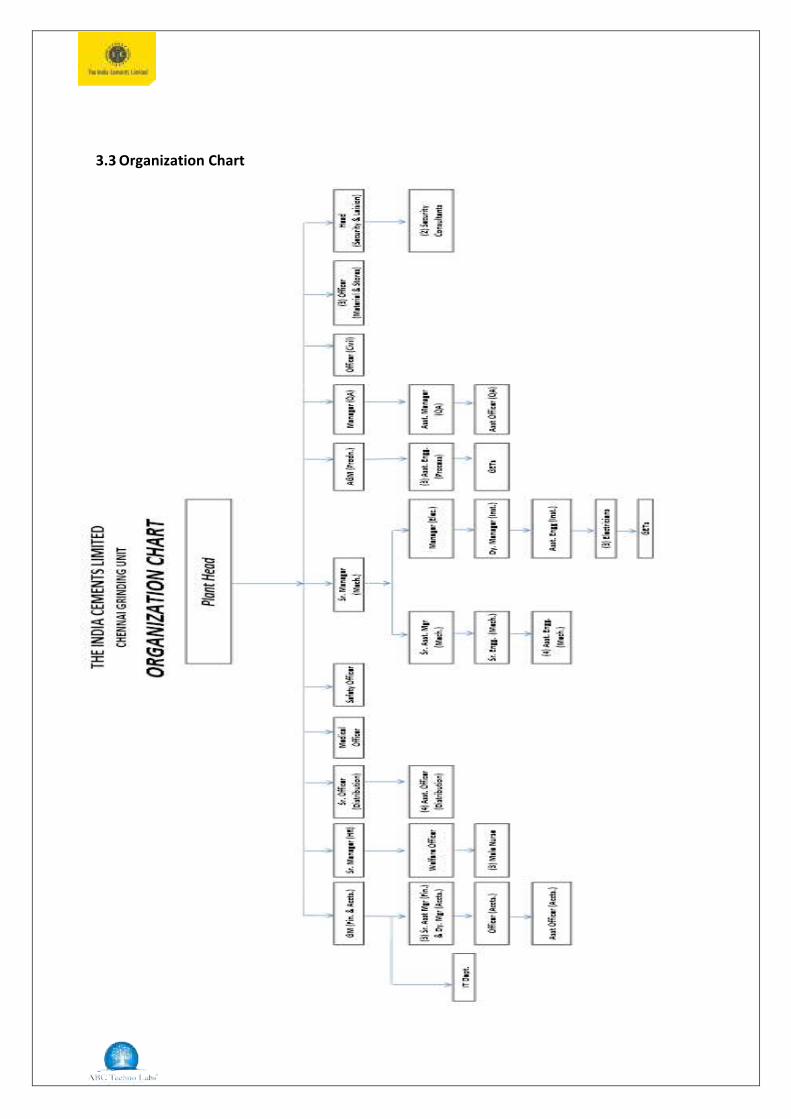
3.3 Organization Chart

HEALTH & SAFETY POLICY

3.4 Process Flow & Description
The Process Flow Sheets are given as Fig. The manufacturing process comprises of the
following activities.
• Receipt of Clinker from ICL Units located in Tamil Nadu and Andhra Pradesh.
• Storage of Clinker in closed RCC Silo
• Receipt of Fly ash form NCTPS
• Storage of Fly ash in a closed Silo
• Grinding of Clinker, Gypsum and Fly ash
• Packing of OPC & PPC for dispatch through trucks/railway sliding.
Clinker received from various units located at Andhra Pradesh and Tamil Nadu will be
transported to the proposed grinding unit through Wagons. For this purpose ICL has
obtained necessary approval from the Southern Railways for laying a Railway-siding from
the nearby Railway station located at Athipattu.
The clinker will be unloaded from the Wagon by mechanical mans for which a Wagon
Tippler will be provided.
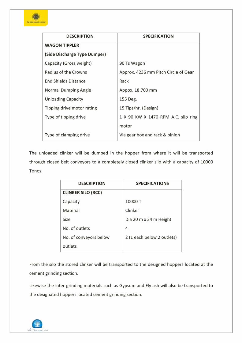
DESCRIPTION SPECIFICATION
WAGON TIPPLER
(Side Discharge Type Dumper)
Capacity (Gross weight)
Radius of the Crowns
End Shields Distance
Normal Dumping Angle
Unloading Capacity
Tipping drive motor rating
Type of tipping drive
Type of clamping drive
90 Ts Wagon
Approx. 4236 mm Pitch Circle of Gear
Rack
Appox. 18,700 mm
155 Deg.
15 Tips/hr. (Design)
1 X 90 KW X 1470 RPM A.C. slip ring
motor
Via gear box and rack & pinion
The unloaded clinker will be dumped in the hopper from where it will be transported
through closed belt conveyors to a completely closed clinker silo with a capacity of 10000
Tones.
DESCRIPTION SPECIFICATIONS
CLINKER SILO (RCC)
Capacity
Material
Size
No. of outlets
No. of conveyors below
outlets
10000 T
Clinker
Dia 20 m x 34 m Height
4
2 (1 each below 2 outlets)
From the silo the stored clinker will be transported to the designed hoppers located at the
cement grinding section.
Likewise the inter-grinding materials such as Gypsum and Fly ash will also be transported to
the designated hoppers located cement grinding section.

DESCRIPTION SPECIFICATIONS
COVERED STOCK FILE
Material
Bulk density
Lump size
Moisture
Capacity
Gypsum
1.3 t/m3
0-200 mm
0-12%
2000 T
Clinker, Gypsum and Fly ash will be drawn for cement grinding at the required proportions.
Then this material will be ground in a close circuit ball-mill. In the ball-mill the feed materials
will be grounded finely because of the collision with the grinding media available in the mill
chamber. The grounded material will be conveyed to the Sepol-separator by means of the
Elevator, where the coarse material will be separated and re-circulated to the mill for
further grinding. The finely grounded material will be transported to the closed cement silo
by means of Belt conveyor and Elevator.
Two completely closed concrete silos will be available for storing the grounded cement. The
cement will be drawn for packing through the Air-slides and Elevator. The drawn cement will
be passed through a nip-trap to separate any foreign material such as broken grinding
media. Then it is stored in a hopper from where it will be packed in bags by means of
Electronic packing devise. The packed cement will be conveyed through the belt conveyors
to the tracks for dispatching the cement bags to the required place.
Summary of Hazard Identification Issues


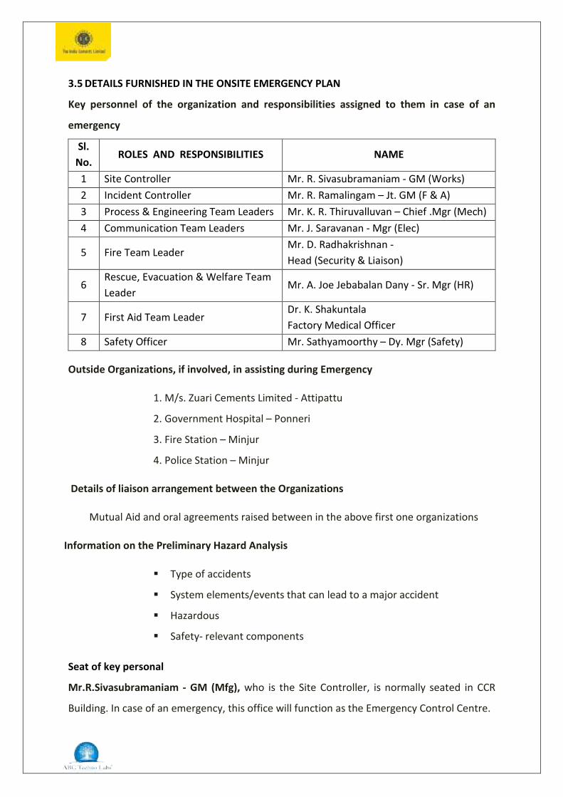
3.5 DETAILS FURNISHED IN THE ONSITE EMERGENCY PLAN
Key personnel of the organization and responsibilities assigned to them in case of an
emergency
Sl. No.
ROLES AND RESPONSIBILITIES NAME
1 Site Controller Mr. R. Sivasubramaniam - GM (Works) 2 Incident Controller Mr. R. Ramalingam – Jt. GM (F & A) 3 Process & Engineering Team Leaders Mr. K. R. Thiruvalluvan – Chief .Mgr (Mech) 4 Communication Team Leaders Mr. J. Saravanan - Mgr (Elec)
5 Fire Team Leader Mr. D. Radhakrishnan - Head (Security & Liaison)
6 Rescue, Evacuation & Welfare Team Leader
Mr. A. Joe Jebabalan Dany - Sr. Mgr (HR)
7 First Aid Team Leader Dr. K. Shakuntala Factory Medical Officer
8 Safety Officer Mr. Sathyamoorthy – Dy. Mgr (Safety)
Outside Organizations, if involved, in assisting during Emergency
1. M/s. Zuari Cements Limited - Attipattu
2. Government Hospital – Ponneri
3. Fire Station – Minjur
4. Police Station – Minjur
Details of liaison arrangement between the Organizations
Mutual Aid and oral agreements raised between in the above first one organizations
Information on the Preliminary Hazard Analysis
Type of accidents
System elements/events that can lead to a major accident
Hazardous
Safety- relevant components
Seat of key personal
Mr.R.Sivasubramaniam - GM (Mfg), who is the Site Controller, is normally seated in CCR
Building. In case of an emergency, this office will function as the Emergency Control Centre.

Emergency Control Centre
The Emergency Control Centre in CCR located in the CCR Building. The following Emergency
facilities are available in the Emergency Control Centre:
- P & T Telephones
- Fax
- Intercoms
- Local Area Plan (Topographical Plan)
- Site Plan of the factory
- Predominant Wind Direction and Speed charts
- Fire Extinguishers as given in Annexure
- List of Key Personnel and their Telephone No
- List of neighbouring factories with the contact
personnel and the telephone no.
- List of Government Agencies and their contact
telephone no
- Fire Suit
- Breathing Apparatus Set
- Face Masks
- Emergency Lights
- First Aid Items
- White Board with Marker Pens
- Sufficient numbers of Emergency Plan copies and
- Public Address System
3.6 Details regarding Warning, alarm and safety and Security systems
An Emergency siren is provided in the Time Office Building; this will be sounded on the
instruction of the Site Controller or Incident Controller in the absence of Site Controller
when any fire is noticed in any fire hazard area.
The factory is surrounded by a compound wall and the security personnel sufficient in
number shall be deployed for surveillance of the factory premises round the clock.
Suitable procedures have been devised for those personnel who remain behind for the
critical plant operations; this critical plant shut-down will be shut down only in events where
immediate emergency evacuation is required. To minimize damage from emergency, the
Rescue Officer is assigned with the additional responsibility of shutting them down
emergency; the Rescue Officer is assigned with the additional responsibility of shutting
them down.
Alarm and Hazard control plans in line with disaster control and hazard control planning,
ensuring the necessary technical and organizational precautions
The Electrical siren that is installed in the Admin building will be used for the emergency
warning.
* EMERGENCY: Wailing sound for 3 minutes.
* ALL CLEAR : Continuous blast for 3 minutes.
All department heads and designated personnel have inter-com phone connection for
communication to aid in the accountability of the employees. Therefore, all the department
heads must know the attendance of their employees on any given day to account accurately
for their personnel.
Reliable measuring instruments, control units and servicing of such equipment
Safe instruments will be used
Required instrument inter-locks are provided
Redundant trips will also be provided
Emergency push-button trips will be provided locally and in the control room
All critical instruments will be provided with battery back-up
Precautions in designing of the foundations and load- bearing parts of the building
Adequate factor of safety will be provided in designing the foundations of all the buildings
as well as the equipments. The buildings and the structures will be periodically maintained
in tidy condition as per the Building Code of practice and relevant acts.
Continuous surveillance of operations
Round the clock surveillance is established in the factory premises
Maintenance and repair work according to the generally recognized rules of Good
Engineering Practices
Electrical maintenance system will be streamlined through check- lists covering preventive
maintenance, half-yearly, yearly, turn-around and daily maintenance; this includes
maintenance of equipment like motors, switch-gears, batteries, etc. The details of work to
be done in each area are listed and codified. The records are computerized; all shut-down
works are pre-planned and requirements of spares, etc. provisioned through the systemic
coordination with the other service and operation departments. Predictive maintenance in
the plant is highly evolved and job specific. The job history is computerized and the same is
used in case of trouble- shooting also. The details about the equipments are maintained in
the areas responsible for the maintenance activities. A Maintenance Engineer performs
daily- LLF (Look, Listen and Feel) inspection to identify any abnormality. Process parameters
are monitored by operating staff and logged in.
Details of communication facilities available during emergency and those required for an
Off-site Emergency
• Mobile and Intercom phones within the factory premises
• P & T Telephone Lines and
• Public Addressing System
Details of fire- Fighting and other facilities available
• Fire Fighting Equipments fixed throughout the Factory-List enclosed in the Annexure.
• Exclusive Fire Water Storage with the capacity of 460KL within the Factory Premises.
• Electrical Pump, Alternate Diesel with Jockey Pump with the pressure capacity of 7.0
Kg/cm2
• Fire Hydrant Layout enclosed in the annexure.
Details of First Aid and Hospital Services available and their adequacy
• First - Aid Boxes with medicines are proposed to provide in various sections of the
Factory.-List of First Aid Boxes/Location are enclosed in the Annexure
• Required Number of persons are proposed to train in the First - Aid by St. John
Ambulance
• Round the Clock Ambulance service is available
• In case of serious emergency for further treatments the management has a tie-up
with nearest hospital
MAIN STAGES OF EMERGENCY
Major Emergency goes through the following main stages:
1. Communication during Emergency
2. Declaration of Emergency by raising the Alarm
3. Implementation of the Emergency Combat Procedures and
4. Rescue.
1. Communication during Emergency
The person first noting the emergency has to inform to shift-in-charge of the
respective section. On assessing the situation, shift-in-charge will inform to all the
concerned as per the guidelines given in the communication net-work.
2. Determination of Emergency
On receipt of information, Incident Controller rushes to the site, assess the situation
and advises them to tackle the situation/emergency. Then he informs the Site Main
Controller and on the instruction of the Site Main Controller he instructs the central
control room to raise the siren.
In case of emergency, the siren will be raised in short wailing tone. On hearing the
siren, all personnel will assemble at assembly points. The personnel assigned with the
emergency duty will report to the respective key personnel at the emergency control
centre and take orders.
3. Implementation of Emergency Combat Procedures
On hearing the siren / information over phone, all key personnel would assemble at
emergency control centre and take orders from the site Main controller and play their
roles as defined. In connection with the Emergency Operations to be carried out in an
orderly and sequential manner, the following teams have been formed to assist the
coordinators so as to restore the normalcy at the earliest:

I. Process & Engineering Team Leaders
II. Fire Team Leader
III. Communication Team Leaders
IV. Rescue, Evacuation and Welfare Team Leader
V. First Aid Team Leader
All others will remain in the Assembly Points until the Emergency is over which is
indicated by the long ALL CLEAR SIGNAL. Depending on the wind direction and
incident spot, all employees (including company employees as well as contract
employees) and visitors should choose the escape route to reach the Assembly
Points. Head count would be taken at the Assembly Point to ascertain that no one is
trapped / missing in the plant area.
4. Rescue and Rehabilitation
In order to ensure that all the persons are safe, Head Count will be taken. In case of
any difference in the count, rescue team will be pressed into service to rescue the
victims.
Head Count System
Number of persons assembled in the Emergency Assembly Point should be informed
to the Site Controller by Communication Team Leaders. The number of company
employees, contract employees and visitors inside the plant at that point of time will
be informed to the Site Controller within 15 minutes by the Human Resources
Manager and the Security Officer respectively. Site Main Controller will match the
figures and if needed advice the Rescue, Evacuation and Welfare Team Leader to
search for the trapped employees.
EMERGENCY CALL OFF
Site Emergency Controller will check-up the area along with Incident Controller and Process
& Engineering Team and Fire Team Leader so as to declare Emergency Call Off by raising
continuous long siren.
Communication Team Leaders will arrange to make announcements with public address
system.

TRAINING
The company believes that any job or task can be performed efficiently through good
training. Human Resources Department takes care of the training needs of the factory. The
Emergency Control is also a task connected with the industrial activity, which requires
training of connected persons for effective management of the task. Training and re-training
are imparted in two stages.
Induction training is given to the facilitators and other members of the Emergency team.
The role of each and every facilitator and the team would be perfected by Mock-Drills on a
given emergency situation.
RESPONSIBILITIES AND DUTIES
DUTIES OF THE PERSON NOTICING THE EMERGENCY
The primary responsibility of informing any Emergency situation to the Incident Controller
shall be religiously followed by the person, who notices the Fire/emergency situations in the
factory premises. In turn, the Incident Controller would consult with the Site Controller after
having assessed the Emergency Situation and declare Emergency without any further loss of
time. The siren will be blown for a longer duration of 3 minutes, at intermission of 15
seconds “ON” and 5 seconds “OFF” for 5 times.
The first responder shall be the vocal alerting system through voice audibility, pitch, volume
and contents of the message. The person who notices the Emergency shall be determined
to react and rise up to the occasion through periodical rehearsals and training. Since the
response time to the Emergency Scenario is the most critical component of combating the
emergencies, his reliable and specific communication about the nature, magnitude and
severity of the incident shall be clearly shown by his action of carrying the Red Flag hoisted
nearby.
DUTIES OF SITE CONTROLLER / INCIDENT CONTROLLER:
The Site Controller shall have the control options (in his absence) the Incident Controller
shall have the Scenario Analysis to initiate the Level I or Level II Emergencies:
LEVEL I EMERGENCY:
Minor Emergency managed by Department Level
LEVEL II EMERGENCY:
Possible Emergencies like Fire or toxic release that can be controlled by factory level,
The Site Controller / Incident Controller shall be able Carryout:
• How to implement the On-Site Emergency Plan
• How to implement the incident Control system
• How to identify, to the extent possible, all credible Accident Scenarios or the
conditions present
• How to address the site analysis, use of Engineering Controls, hazardous material
handling procedures and use of new techniques
• How to determine- through monitoring, when personal protective equipments or
respiratory protection is required
• How to provide training to the First Responders based on their duties and functions
within the factory premises; the skill and training required for all new Responders
shall be conveyed to them through training , before they are permitted to take part
in the actual Emergency Situation
• A First Responder Awareness Level employee is an individual who is likely to witness
or discover a hazard and who, through training, is expected to initiate a response
system by notifying the appropriate authorities of the Fire / hazardous chemical
splashing. They are not expected to take further action
• A First Responder Operation Level is an individual who is expected to respond to the
fire scenario as part of initial action to protect nearby personnel, property or the
environment from the effects of the fire. They are trained to respond defensively to
the fire scenario without necessarily being expected to extinguish the fire
• They shall have the knowledge of Hazards and the Risks associated with employees
wearing in personal protective clothing
• When to decide for termination procedures
DUTIES OF THE PROCESS & ENGINEERING TEAM
• The Process & Engineering Team Leaders shall be able to demonstrate the
implementation of the Emergency Response Plan
• The knowledge of the classification, identification and verification of known and
unknown materials by using field survey instruments equipments shall be acquired
• Ability to function within the assigned role in the incident command system shall be
exercised
• The knowledge of the selecting and using the specialized personal protective
equipments shall be acquired
• The knowledge of the in-depth Hazard and Risk Assessment shall be possessed
• Performance of advance control, containment and confinement operations within
the capabilities of the resources available shall be secured
• Understanding of the termination procedures shall also be propagated.
DUTIES OF THE FIRE TEAM
Identification of the standard fire-fighting functions or evaluations expected of them based
on the credible accident scenario to be assigned, including fire scenario assessment shall be
performed simultaneously. The specific Fire-Safety Rules, Procedures and First-aid / Medical
Attention services shall be performed according to the type of each credible accident
scenario.
Whenever hot work operations are essential in the course of any industrial activities, the
following Six Steps Rules shall be adhered in the interest of safety:
1. Conduct safety meeting with other officers
2. Put up warning signs at the site
3. Move combustibles away from the hot work site
4. Shield combustibles with fire blankets or welder’s blankets
5. Provide fire watch
6. Have nearby appropriate fire extinguisher and telephone
7. Evacuate the area, if fire cannot be extinguished immediately and

8. Protect stored materials with a thermal barrier such as half-an-inch gypsum
sheet board as soon as possible
Effective communication ensures that the fire-fighting crew understands their
responsibilities during an assigned work. Effective coordination prevents conflicting
activities and ensures that a proper sequence is followed, while conducting an assigned task.
This becomes increasingly important as more agencies such as Tamilnadu Fire & Rescue
Service and Mutual Aid Member would be involved in fire-fighting operations. Written code
of practice shall be observed during fire-fighting by each and every-one of the crew.
It is not necessary to develop standard operating procedures regarding every possible
exposure to carbon-monoxide and carbon-di-oxide atmosphere in the course of fire- fighting
activities. What is expected is that procedures would be followed by way of wearing
personal protective equipments, which is mandatory for their own protection.
Apart from the active fire-fighting crew, the Incident Controller and Fire Team Leader shall
wear personal protective equipments invariably. Fit testing shall be conducted for one and
all fire-fighting crew and equipment shall be made available in the correct size.
DUTIES OF THE COMMUNICATION TEAM
Emergency communication and warning protocols, processes and procedures shall
be developed, periodically tested and used to alert people potentially impacted by
an actual or impending emergency;
The communication Team Leaders shall develop procedures to disseminate and
respond to request for pre-disaster, disaster and post-disaster information including
procedures to provide information to the media and other external audience and
deal with their enquiries
Effective communication shall be ensured in the interest of safety
The channel shall be monitored before transmitting
The message shall be planned suitably before pushing the transmitter switch
The push-to talk button in the Radio shall be pressed first and then wait for one
second before starting the message; otherwise the first part of the message would
be cut off due to the transmitter to work at its full power

The micro-phone shall be held two inches from the mouth
The unit or person shall be first identified
The message transmitted shall be acknowledged by saying “GO AHEAD”. If long
message could not be taken for some reasons, simply “STANDBY” shall be recorded
until the problem is solved
While transmitting a number with two or more digits, ; first the entire number shall
be given and then each digit separately; for example, the number “sixty three” shall
be recorded as “63” first and then “six” and “three” shall be followed
• Exclusive frequency shall be ensured for Emergency Management Services and the
back-ground noise shall be reduced as much as possible
• There shall be adequate proper communication from each stage of a plan to the
next, so that the Hazard Management Decisions could be understood, recorded and
audible. One way of achieving this by summarizing the key information of fire
events in the factory premises
• The summary of the Key Information shall be a living document, which in its
simplest form may be a compilation of entire details. It should convey information
to all those who are responsible for operations in full, which is concise and easily
read
DUTIES OF THE RESCUE, EVACUATION & WELFARE TEAM
• Because air-way maintenance is one of the very important skills that has to be
learnt by the Rescue Team Members and also the respiratory system shall be
the first of the body systems to be reviewed in the course of an emergency
• Unconscious persons who have not suffered trauma shall be placed in a side-
laying or RECOVERY POSITION to help keeping air-way open
• Improperly lifting or moving a person can result in injury to either the responder
or to the injured person. By exercising good body mechanics, the possibility of
injuring self as well as the injured will be reduced. Good Body Mechanics means
using the strength in the large muscles from the legs to lift a person instead of
applying back muscles
• To lift safely, the Rescue Crew shall keep certain guide-lines in mind
• Before attempting to move a person, check the weight of the patient; if required,
another person may be called for the help. The rescue work shall be carried out
in an effective and helpful manner If the patient is on the floor or on the ground
during an emergency situation, the rescue team member may have to drag the
person away from the site
• Instead of trying to lift them and carry. Every effort shall be made to pull the
person in the direction of long axis of the body in order to provide as much spinal
protection for the person as possible. This sort of CLOTHES DRAG is the simplest
way to move a person in an emergency
• If the person is dressed in cloths that could tear away easily during clothes drag
(for example, burnt partially) the person injured shall be moved by using a
blanket or large bed sheet, which is termed as BLANKET DRAG
• If any large sheet is not readily available, the injured person shall be carried by
ARMS-TO-ARMS DRAG by placing the hands under the lying person’s arm-pits
from the back of the person and grasping the person’s fore-arm
• There shall be close coordination and effective communication between the
Rescue Team and the First Aid team.
• The Rescue, Evacuation & Welfare Team Leader shall also hold responsibility for
the shutting down the critical plants in the course of their emergency rescue
operations in the factory premises.
DUTIES OF THE FIRST – AID TEAM
The First Aid Team Leader shall establish logical capability and the Procedures to locate,
store, distribute, maintain, test and account for Services, personnel, resource materials and
facilities procured for the Purpose of supporting the plan;
• Procedures shall include, but not limited to, the following:
1. Control of access to the area affected by the emergency
2. Identification of personnel engaged in emergency activities at the scene of
incident
3. Accounting for the personnel engaged in various activities
4. Accounting for the personnel affected, displaced or injured by the incident

5. Mobilization and Demobilization of resources
6. Provision of temporary, short-term or long-term shelters, feeding and care
of people displaced by the emergency
7. Recovery, identification and safe-guarding of human remains
8. Provision of mental health and physical well-being of the individuals affected
by the emergency
9. Provision for managing the critical incident stress for responders
The First Aid Team Leader shall develop functional and administrative procedures to support
the entire sequence of operations like pre-disaster, disaster and post-disaster scenarios.
DUTIES OF THE EMPLOYEES
Employees in the factory including contractors and their contract workers shall, to the
extent to which they are expected, that is, within their competency and skills, shall comply
with all procedures and protection relating to the prevention and control of major accidents
within the factory premises
They shall comply with all emergency procedures should a major accident or near miss
occur
They shall report promptly to the Incident Controller / shift-in-charge any matter of which
they are aware that they may affect the facility compliance
They shall take, within the scope of their job, and without being placed at any disadvantage,
corrective action and, if necessary, interrupt the operations / processes of the factory,
where, on the basis of their training and skills, they have responsible jurisdiction to believe
that there is an imminent danger of a major accident and notify to the Incident Controller /
Shift-in-charge or raise an alarm, as appropriate, before or as far as possible, after taking
such action
They shall discuss with the Emergency Coordinating Officers any potential hazards that they
consider are capable of generating a major accident and they also have the right to notify
the relevant District Administration Authorities of those hazards
They shall also be consulted through appropriate consultative Mechanism in order to
provide the safe system of work in and around the factory premise. In particular, they shall
invariably be consulted about the Hazard Identification, the maintenance and
Implementation of the Safety Management Systems and also on the revision as well as
updating periodically of the On- Site Emergency Plan.
SOCIAL IMPACT ASSESSMENT, R&R ACTION PLAN
The proposed expansion of cement grinding capacity enhancement will not require any
acquisition of lands, hence Social Impact Assessment and R&R Action Plan are not
necessary.