rin-the-cabinet i/o. maximum size of a bl67 station … devicenet gateway † modular i/o †...
TRANSCRIPT

BL67
Phone: 800.894.0412 - Fax: 888.723.4773 - Web: www.clrwtr.com - Email: [email protected]

BL67 Power DistributionPower Overview
The power supply for a BL67 station is fed via the power connector on the PROFIBUS® gateway or directly from thenetwork on the DeviceNet™ gateway. Power feeder modules can be added to the system at any point to provide a freshisolated supply of power to all I/O connected to its right.
Internal Power Consumption via Module Bus
The amount of BL67 modules that may be supplied via the internal module bus depends on the respective nominal currentIMB of the individual modules on the module bus. The sum of the nominal current inputs of the connected BL67 modulesmust not exceed 1.5 A. If the I/O assistant software is used, an error message is generated automatically via the <Station -Verify> as soon as the system supply via the module bus is no longer sufficiently guaranteed.
To calculate current draw on DeviceNet: Add IMB(24) for all modules. Then add VI and VO for electronic modules to the leftof the first power feed module. Next, add the current draw of the I/O devices.To calculate current draw on PROFIBUS gateway power connector for VI: Add IMB for all modules. Then add VI current forall modules to the left of the first power feed module. Next, add the current draw of the input devices.For VO, add the VO current for all modules to the left of the first power feed module. Next, add the current draw of theoutput devices.
VMB = Module bus powerVI = Input powerVO = Output powerIMB = Module bus currentIMB(24) = Effective current draw from gateway at 24 VDC supply
Module
Nominal 1)Current at 5 V
IMB
Effective Draw 2)from Gateway at 24 VDC
IMB(24)
Nominal 3)Current from
VI
Nominal 4)Current from
VO
BL67-GW-DPV1 - ≤150 mA
BL67-GW-DN - ≤100 mA
BL67-PF-24VDC ≤30 mA ≤9 mA
BL67-4DI-P ≤30 mA ≤9 mA ≤40 mA
BL67-8DI-P ≤30 mA ≤9 mA ≤40 mA
BL67-4DO-0.5A-P ≤30 mA ≤9 mA ≤100 mA
BL67-4DO-2A-P ≤30 mA ≤9 mA ≤100 mA
BL67-8DO-0.5A-P ≤30 mA ≤9 mA ≤100 mA
BL67-2AI-V ≤35 mA ≤10 mA ≤12 mA
BL67-2AI-I ≤35 mA ≤10 mA ≤12 mA
BL67-2AI-TC ≤35 mA ≤10 mA ≤30 mA
BL67-2AI-PT ≤45 mA ≤13 mA ≤45 mA
BL67-2AO-I ≤40 mA ≤12 mA ≤50 mA
BL67-2AO-V ≤60 mA ≤17 mA ≤50 mA
BL67-1RS232 ≤100 mA ≤28 mA ≤50 mA
BL67-8XSG-PD ≤30 mA ≤9 mA ≤100 mA
BL67-1SSI ≤50 mA ≤15 mA ≤50 mA
BL67-4DI-PD ≤30 mA ≤9 mA ≤100 mA
BL67-8DI-PD ≤30 mA ≤9 mA ≤100 mA
Phone: 800.894.0412 - Fax: 888.723.4773 - Web: www.clrwtr.com - Email: [email protected]

BL67
4A4A
IO
II
VOVI
IO
II
VOVI
Isolation
System Power
Field Power VMB(24V) IMB(24V)
VMB(5V) IMB(5V)
A power feeder module provides a new isolated segment for all modules to its right.
Isolation of Field Power VI’ VOVI’ VO’ VMB from Power on Gateway
IMB(5V) < 1.5AII < 4A (protected)IO < 8A
VMB = Module Bus PowerVI = Input PowerVO = Output Power
PROFIBUS® , Ethernet and CANopen System
4A4A
IO
II
VOVI
IO
II
VOVI
Isolation
System Power
Field Power VMB(24V) IMB(24V)
VMB(5V) IMB(5V)
A power feeder module provides a new isolated segment for all modules to its right.
Isolation of Field Power VI’ VOVI’ VO’ VMB from DeviceNet™
IMB(5V) < 1.5AII < 4A (protected)IO < 8A
VMB = Module Bus PowerVI = Input PowerVO = Output Power
DeviceNet™ System
Applying Power to BL67
Phone: 800.894.0412 - Fax: 888.723.4773 - Web: www.clrwtr.com - Email: [email protected]

Environmental ConditionsIntended Application Environments
• BL67 does not need an enclosure• Mount directly on machine or conveyor• Rugged design provides protection against dirt, dust and liquids
Not intended for These Environments• Continuous submersion• 100 percent humidity• High pressure washdown
Note: For higher levels of protection consider fully potted AIM stations
General Environmental
Potential isolation Via optocoupler
Operating temperature 32° to +131°F (0° to +55°C)
Storage temperature -13° to +185°F (-25° to +85°C)
Relative humidity 5 to 95% (indoor), noncondensing
Vibration 1.0 g 5-10 Hz
Shock 15 g
Protection class IP 67, NEMA 1, 3, 4, 12, 13
Electromagnetic compatibility (EMC) According to EN 61131-2
Housing material PC-V0 (Lexan), Nickel plated brass
Approvals CE
UL (pending)
CSA (pending)
Phone: 800.894.0412 - Fax: 888.723.4773 - Web: www.clrwtr.com - Email: [email protected]
BL67-GW-DN
DeviceNet Gateway • Modular I/O• Fieldbus Independent Configuration
• IP 67 Protection• Various I/O Styles
Electrical• Operating Current: <600 mA from VMB
• Supply Current: <8 A to I/O (from DeviceNet)• Backplane Current: <1.5 A (from DeviceNet)
Mechanical• Operating Temperature: 0 to +55°C (+32 to +131°F)• Protection: IP 67• Vibration: 5 g @ 10-500 Hz
Material• Housing: PC-V0 (Lexan)
Diagnostics (Logical)• Diagnostic information available through the DeviceNet I/O map
Diagnostics (Physical)• LEDs to indicate status of DeviceNet and Module Bus communication
Male Female
5-Pin 5-Pin
DeviceNet minifast ® Pinouts
1 = Shield2 = V+3 = V-4 = CAN_H5 = CAN_L
Note: Power feeding modules may be used for I/O current supply to prevent overloading the DeviceNet power supply.
Phone: 800.894.0412 - Fax: 888.723.4773 - Web: www.clrwtr.com - Email: [email protected]

BL67
Female
4-Pin
Ethernet Pinout
BL67-GW-ENBL67-PG-EN
ModBus TCP/IPEthernet Gateways
• Modular I/O• Fieldbus Independent Configuration
• IP 67 Protection• Various I/O Styles
Electrical• Operating Current: <600 mA from VMB
• Input Supply Current: <4 A (from VI)• Output Supply Current: <8 A (from VO)• Backplane Current: <1.5 A (from VMB)
Mechanical• Operating Temperature: -12 to +55°C (-13 to +131°F)• Protection: IP 67• Vibration: 5 g @ 10-500 Hz
Material• Housing: PC-V0 (Lexan)
Diagnostics (Logical)• Diagnostic information available through the system I/O map
Diagnostics (Physical)• LEDs to indicate status of Network and Module Bus communication
Programmability• PG in part number designates a programmable gateway• Progammable according to IEC 61131.3 using CodeSys (includes ladder logic)• Use CodeSys to create logic programs to control local I/O
Male
5-Pin
5-pin minifast ® Power Pinout
1 = TD+2 = RD+3 = TD-4 = RD-
1 = Gnd2 = Gnd3 = PE4 = VI
5 = VO
Phone: 800.894.0412 - Fax: 888.723.4773 - Web: www.clrwtr.com - Email: [email protected]
Female
4-Pin
Ethernet Pinout
BL67-GW-EN-IPBL67-PG-EN-IP
Ethernet IPEthernet Gateways
• Modular I/O• Fieldbus Independent Configuration
• IP 67 Protection• Various I/O Styles
Electrical• Operating Current: <600 mA from VMB
• Input Supply Current: <4 A (from VI)• Output Supply Current: <8 A (from VO)• Backplane Current: <1.5 A (from VMB)
Mechanical• Operating Temperature: -12 to +55°C (-13 to +131°F)• Protection: IP 67• Vibration: 5 g @ 10-500 Hz
Material• Housing: PC-V0 (Lexan)
Diagnostics (Logical)• Diagnostic information available through the system I/O map
Diagnostics (Physical)• LEDs to indicate status of Network and Module Bus communication
Programmability• PG in part number designates a programmable gateway• Progammable according to IEC 61131.3 using CodeSys (includes ladder logic)• Use CodeSys to create logic programs to control local I/O
Male
5-Pin
5-pin minifast ® Power Pinout
1 = TD+2 = RD+3 = TD-4 = RD-
1 = Gnd2 = Gnd3 = PE4 = VI
5 = VO
Phone: 800.894.0412 - Fax: 888.723.4773 - Web: www.clrwtr.com - Email: [email protected]

BL67
Female
4-Pin
Ethernet Pinout
BL67-GW-EN-PN
ProfinetEthernet Gateways
• Modular I/O• Fieldbus Independent Configuration
• IP 67 Protection• Various I/O Styles
Electrical• Operating Current: <600 mA from VMB
• Input Supply Current: <4 A (from VI)• Output Supply Current: <8 A (from VO)• Backplane Current: <1.5 A (from VMB)
Mechanical• Operating Temperature: -12 to +55°C (-13 to +131°F)• Protection: IP 67• Vibration: 5 g @ 10-500 Hz
Material• Housing: PC-V0 (Lexan)
Diagnostics (Logical)• Diagnostic information available through the system I/O map
Diagnostics (Physical)• LEDs to indicate status of Network and Module Bus communication
Male
5-Pin
5-pin minifast ® Power Pinout
1 = TD+2 = RD+3 = TD-4 = RD-
1 = Gnd2 = Gnd3 = PE4 = VI
5 = VO
Phone: 800.894.0412 - Fax: 888.723.4773 - Web: www.clrwtr.com - Email: [email protected]

BL67-GW-DPV1BL67-PG-DP
PROFIBUS-DP Gateway • Modular I/O• Fieldbus Independent Configuration
• IP 67 Protection• Various I/O Styles
Electrical• Operating Current: <50 mA from VI
• Supply Current: <10 A to I/O (from VI and VO)• Backplane Current: <1.5 A (from VI)
Mechanical• Operating Temperature: -25 to +55°C (+32 to +131°F)• Protection:IP 67• Vibration: 5 g @ 10-500 Hz
Material• Housing: PC-V0 (Lexan)
Diagnostics (Logical)• Diagnostic information available through the PROFIBUS-DP interface
Diagnostics (Physical)• LEDs to indicate status of PROFIBUS-DP and Module Bus communication
Programmability• PG in part number designates a programmable gateway• Progammable according to IEC 61131.3 using CodeSys (includes ladder logic)• Use CodeSys to create logic programs to control local I/O
Note: Power feeding modules may be used for I/O current supply to prevent overloading the gateway power supply.
Male Female
5-Pin 5-Pin
eurofast PROFIBUS Pinouts
1 = 5 VDC*2 = BUS _A3 = Gnd4 = BUS_B
5 = Shield* Female
connector only
Male
5-Pin
minifastPower Pinouts
1 = Gnd2 = Gnd3 = PE4 = VI
5 = VO
Phone: 800.894.0412 - Fax: 888.723.4773 - Web: www.clrwtr.com - Email: [email protected]

BL67
BL67-GW-CO
CANopen Gateway • Modular I/O• Fieldbus Independent Configuration
• IP 67 Protection• Various I/O Styles
Electrical• Operating Current: <600 mA from VI
• Supply Current: <10 A to I/O (from VI and VO)• Backplane Current: <1.5 A (from VI)
Mechanical• Operating Temperature: -25 to +55°C (+32 to +131°F)• Protection: IP 67• Vibration: 5 g @ 10 to 500 Hz
Material• Housing: PC-V0 (Lexan)
Diagnostics (Logical)• Diagnostic information available through the CANopen interface
Diagnostics (Physical)• LEDs to indicate status of CANopen and Module Bus communication
Note: Power feeding modules may be used for I/O current supply to prevent overloading the gateway power supply.
Male
5-Pin
minifast ® Power Pinouts
1. = Gnd2. = Gnd3. = PE4. = VI
5. = VO
Male Female
5-Pin 5-Pin
CANopen eurofast ® Pinouts
1. = Shield2. = V+3. = V-4. = CAN_H5. = CAN_L
Phone: 800.894.0412 - Fax: 888.723.4773 - Web: www.clrwtr.com - Email: [email protected]

BL67-GW-CO-T
Service Address
Set
BL67 IO
CANopen Gateway • Modular I/O• Fieldbus Independent Configuration
• IP 67 Protection• Various I/O Styles
Electrical• Operating Current: <600 mA from VMB
• Supply Current: <8 A to I/O (from CANopen)• Backplane Current: <1.5 A (from CANopen)
Mechanical• Operating Temperature: 0 to +55°C (+32 to +131°F)• Protection: IP 67• Vibration: 5 g @ 10-500 Hz
Material• Housing: PC-V0 (Lexan)
Diagnostics (Logical)• Diagnostic information available through the CANopen I/O map
Diagnostics (Physical)• LEDs to indicate status of CANopen and Module Bus communication
Male Female
5-Pin 5-Pin
CANopen minifast ® Pinouts
1 = Shield2 = V+3 = V-4 = CAN_H5 = CAN_L
Note: Power feeding modules may be used for I/O current supply to prevent overloading the CANopen power supply.
Phone: 800.894.0412 - Fax: 888.723.4773 - Web: www.clrwtr.com - Email: [email protected]

BL67-4DI-PBL67-4DI-N
• Modular I/O• Fieldbus Independent Configuration
• IP 67 Protection• Various I/O Styles
4 Discrete Input Modules
Shown with BL67-B-4MB base
Electrical• Operating Current: <30 mA from VMB
<40 mA from VI (...-P)<1 mA from VI (...-N)
Power Distribution• Inputs: VI
• Logic: VMB and VI
Material• Connectors: Nickel-plated brass• Housing: PC-V0 (Lexan)
Diagnostics (Logical)• Diagnostic information available through the fieldbus gateway
Diagnostics (Physical)• LED to indicate module bus communication status as well as I/O
diagnostics• LEDs for each I/O point to indicate on/off status
DA B C
Phone: 800.894.0412 - Fax: 888.723.4773 - Web: www.clrwtr.com - Email: [email protected]

BL67
Inputs Data
Part Number Dra
win
g
Inpu
t Cou
ntCo
nnec
tors
Pino
ut
Inpu
tspe
rCo
nnec
tor
Sens
orSt
yle
Gro
upD
iagn
ostic
sIn
divi
dual
Dia
gnos
tics
Wire
-Bre
akD
etec
tion
I/OM
ap
BL67-4DI-P with BL67-B-4M12* A 4 0-3 S 1 PNP X 1
BL67-4DI-P with BL67-B-2M12* B 4 0-1 2S 2 PNP X 1
BL67-4DI-P with BL67-B-2M12-P* B 4 0-1 2S 2 PNP X 1
BL67-4DI-P with BL67-B-4M8* D 4 0-3 PI 1 PNP X 1
BL67-4DI-P with BL67-B-1M23* C 4 0 M23-4I 4 PNP X 1
BL67-4DI-N with BL67-B-4M12* A 4 0-3 S 1 NPN X 1
BL67-4DI-N with BL67-B-2M12* B 4 0-1 2N 2 NPN X 1
BL67-4DI-N with BL67-B-2M12-P* B 4 0-1 2N 2 NPN X 1
BL67-4DI-N with BL67-B-4M8* D 4 0-3 PI 1 NPN X 1
BL67-4DI-N with BL67-B-1M23* C 4 0 M23-4I 4 NPN X 1
*Note: Base modules sold separately. See page G45.
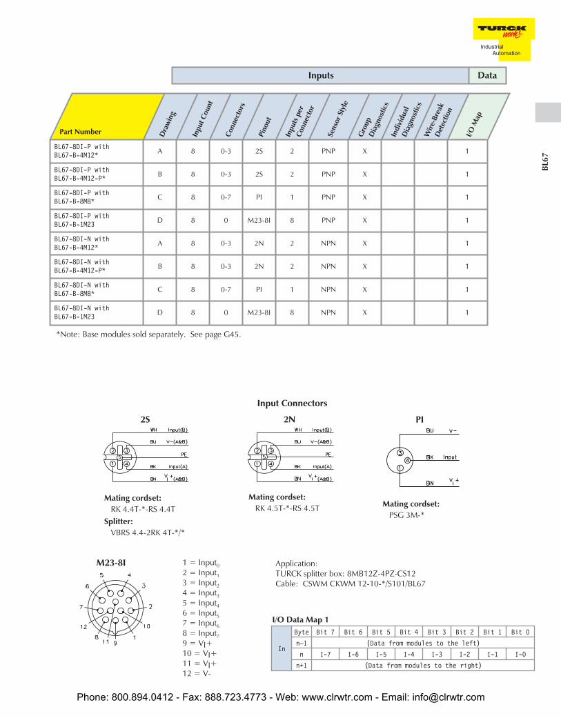
Input Connectors
M23-4I
2S
Mating cordset:RK 4.4T-*-RS 4.4T
Splitter:VBRS 4.4-2RK 4T-*/*
2N
Mating cordset:RK 4.5T-*-RS 4.5T
PI
Mating cordset:PSG 3M-*
In
Byte Bit 7 Bit 6 Bit 5 Bit 4 Bit 3 Bit 2 Bit 1 Bit 0
n–1 (Data from modules to the left)
n Data from next discretemodules I-3 I-2 I-1 I-0
n+1 (Data from modules to the right)
I/O Data Map 1
S
Mating cordset:RK 4.4T-*-RS 4.4T
1=Input0
2=Input1
3=Input2
4=Input3
5=NC6=NC7=NC8=NC9=VI+10=VI+11=VI+12=V-
Phone: 800.894.0412 - Fax: 888.723.4773 - Web: www.clrwtr.com - Email: [email protected]

BL67-8DI-PBL67-8DI-N
• Modular I/O• Fieldbus Independent Configuration
• IP 67 Protection• Various I/O Styles
Electrical• Operating Current: <30 mA from VMB
<40 mA from VI (...-P)<1 mA from VI (...-N)
Power Distribution• Inputs: VI
• Logic: VMB
Mechanical• Operating Temperature: 0 to +55°C (+32 to +131°F)• Protection: NEMA 1,3,4,12,13 / IEC IP 67• Vibration:
Material• Connectors: Nickel-plated brass• Housing: PC-V0 (Lexan)
Diagnostics (Logical)• Diagnostic information available through the fieldbus gateway
Diagnostics (Physical)• LED to indicate module bus communication status as well as I/O
diagnostics• LEDs for each I/O point to indicate on/off status
8 Discrete Input Modules
Shown with BL67-B-4M12 base
DA B C
Phone: 800.894.0412 - Fax: 888.723.4773 - Web: www.clrwtr.com - Email: [email protected]
BL67
Part Number Dra
win
g
Inpu
t Cou
nt
Conn
ecto
rs
Pino
ut
Inpu
tspe
rCo
nnec
tor
Sens
orSt
yle
Gro
upD
iagn
ostic
sIn
divi
dual
Dia
gnos
tics
Wire
-Bre
akD
etec
tion
I/OM
ap
BL67-8DI-P withBL67-B-4M12* A 8 0-3 2S 2 PNP X 1
BL67-8DI-P withBL67-B-4M12-P* B 8 0-3 2S 2 PNP X 1
BL67-8DI-P withBL67-B-8M8* C 8 0-7 PI 1 PNP X 1
BL67-8DI-P withBL67-B-1M23 D 8 0 M23-8I 8 PNP X 1
BL67-8DI-N withBL67-B-4M12* A 8 0-3 2N 2 NPN X 1
BL67-8DI-N withBL67-B-4M12-P* B 8 0-3 2N 2 NPN X 1
BL67-8DI-N withBL67-B-8M8* C 8 0-7 PI 1 NPN X 1
BL67-8DI-N withBL67-B-1M23 D 8 0 M23-8I 8 NPN X 1
*Note: Base modules sold separately. See page G45.
Inputs Data
Input Connectors
In
Byte Bit 7 Bit 6 Bit 5 Bit 4 Bit 3 Bit 2 Bit 1 Bit 0
n–1 (Data from modules to the left)
n I-7 I-6 I-5 I-4 I-3 I-2 I-1 I-0
n+1 (Data from modules to the right)
I/O Data Map 1
2S
Mating cordset:RK 4.4T-*-RS 4.4T
Splitter:VBRS 4.4-2RK 4T-*/*
PI
Mating cordset:PSG 3M-*
2N
Mating cordset:RK 4.5T-*-RS 4.5T
M23-8I 1 = Input0
2 = Input1
3 = Input2
4 = Input3
5 = Input4
6 = Input5
7 = Input6
8 = Input7
9 = VI+10 = VI+11 = VI+12 = V-
Application:TURCK splitter box: 8MB12Z-4PZ-CS12Cable: CSWM CKWM 12-10-*/S101/BL67
Phone: 800.894.0412 - Fax: 888.723.4773 - Web: www.clrwtr.com - Email: [email protected]

BL67-4DO-0.5A-P
• Modular I/O• Fieldbus Independent Configuration
• IP 67 Protection• Various I/O Styles
Electrical• Operating Current: <30 mA from VMB
<100 mA from VO
• Output Current: <0.5 A per output from VO
Power Distribution• Outputs: VO
• Logic: VMB and VO
Material• Connectors: Nickel-plated brass• Housing: PC-V0 (Lexan)
Diagnostics (Logical)• Diagnostic information available through the fieldbus gateway
Diagnostics (Physical)• LED to indicate module bus communication status as well as I/O
diagnostics• LEDs for each I/O point to indicate on/off status
4 Discrete Output Modules
Shown with BL67-B-4M12 base
DA B C
Phone: 800.894.0412 - Fax: 888.723.4773 - Web: www.clrwtr.com - Email: [email protected]

BL67
Part Number Dra
win
g
Out
put
Coun
t
Conn
ecto
rs
Pino
ut
Out
puts
per
Conn
ecto
r
Curr
ent
Styl
e
Indi
vidu
alD
iagn
ostic
s
I/OM
ap
BL67-4DO-0.5A-P with BL67-B-4M12* A 4 0-3 G 1 0.5 A Source 1
BL67-4DO-0.5A-P with BL67-B-2M12* B 4 0-1 2G 2 0.5 A Source 1
BL67-4DO-0.5A-P with BL67-B-2M12-P* B 4 0-1 2G 2 0.5 A Source 1
BL67-4DO-0.5A-P with BL67-B-4M8* D 4 0-3 PO 1 0.5 A Source 1
BL67-4DO-0.5A-P with BL67-B-1M23* C 4 0 M23-4O 4 0.5 A Source 1
*Note: Base modules sold separately. See page G45.
Outputs Data
Output Connectors
Out
Byte Bit 7 Bit 6 Bit 5 Bit 4 Bit 3 Bit 2 Bit 1 Bit 0
n–1 (Data for modules to the left)
n Data for next discrete modules O-3 O-2 O-1 O-0
n+1 (Data for modules to the right)
I/O Data Map 1
2G
Mating cordset:RK 4.4T-*-RS 4.4T
Splitter:VBRS 4.4-2RK 4T-*/*
PO
Mating cordset:PSG 3M-*
G
Mating cordset:RK 4.4T-*-RS 4.4T
M23-4O 1 = Output0
2 = Output1
3 = Output2
4 = Output3
5 = NC6 = NC7 = NC8 = NC9 = VI+10 = VI+11 = VI+12 = V-
Phone: 800.894.0412 - Fax: 888.723.4773 - Web: www.clrwtr.com - Email: [email protected]

BL67-4DO-2A-PBL67-4DO-2A-N
• Modular I/O• Fieldbus Independent Configuration
• IP 67 Protection• Various I/O Styles
Electrical• Operating Current: <30 mA from VMB
<100 mA from VO
• Output Current: <2 A per output from VO
Power Distribution• Outputs: VO
• Logic: VMB and VO
Material• Connectors: Nickel-plated brass• Housing: PC-V0 (Lexan)
Diagnostics (Logical)• Diagnostic information available through the fieldbus gateway
Diagnostics (Physical)• LED to indicate module bus communication status as well as I/O
diagnostics• LEDs for each I/O point to indicate on/off status
4 Discrete Output Modules
Shown with BL67-B-2M12 base
DA B C
Phone: 800.894.0412 - Fax: 888.723.4773 - Web: www.clrwtr.com - Email: [email protected]

BL67
Part Number Dra
win
g
Out
put
Coun
t
Conn
ecto
rs
Pino
ut
Out
puts
per
Conn
ecto
r
Curr
ent
Styl
e
Indi
vidu
alD
iagn
ostic
s
I/OM
ap
BL67-4DO-2A-P with BL67-B-4M12* A 4 0-3 H 1 2 A Source 1
BL67-4DO-2A-P with BL67-B-2M12* B 4 0-1 2H 2 2 A Source 1
BL67-4DO-2A-P with BL67-B-2M12-P* C 4 0-1 2H 2 2 A Source 1
BL67-4DO-2A-P with BL67-B-4M8* D 4 0-3 PO 1 2 A Source 1
BL67-4DO-2A-P with BL67-B-1M23* C 4 0 M23-4O 4 2 A Source 1
BL67-4DO-2A-N with BL67-B-4M12* A 4 0-3 H 1 2 A Sink 1
BL67-4DO-2A-N with BL67-B-2M12* B 4 0-1 2H 2 2 A Sink 1
BL67-4DO-2A-N with BL67-B-2M12-P* C 4 0-1 2H 2 2 A Sink 1
BL67-4DO-2A-N with BL67-B-4M8* D 4 0-3 PO 1 2 A Sink 1
BL67-4DO-2A-N with BL67-B-1M23* C 4 0 M23-4O 4 2 A Sink 1
* Base modules sold separately. See page G45.
Outputs Data
Output Connectors
Out
Byte Bit 7 Bit 6 Bit 5 Bit 4 Bit 3 Bit 2 Bit 1 Bit 0
n–1 (Data for modules to the left)
n Data for next discrete modules O-3 O-2 O-1 O-0
n+1 (Data for modules to the right)
I/O Data Map 1
2H
Mating cordset:RK 4.4T-*-RS 4.4T
Splitter:VBRS 4.4-2RK 4T-*/*
PO
Mating cordset:PSG 3M-*
H
Mating cordset:RK 4.5T-*-RS 4.5T
M23-4O 1 = Output0
2 = Output1
3 = Output2
4 = Output3
5 = NC6 = NC7 = NC8 = NC9 = VI+10 = VI+11 = VI+12 = V-
Phone: 800.894.0412 - Fax: 888.723.4773 - Web: www.clrwtr.com - Email: [email protected]
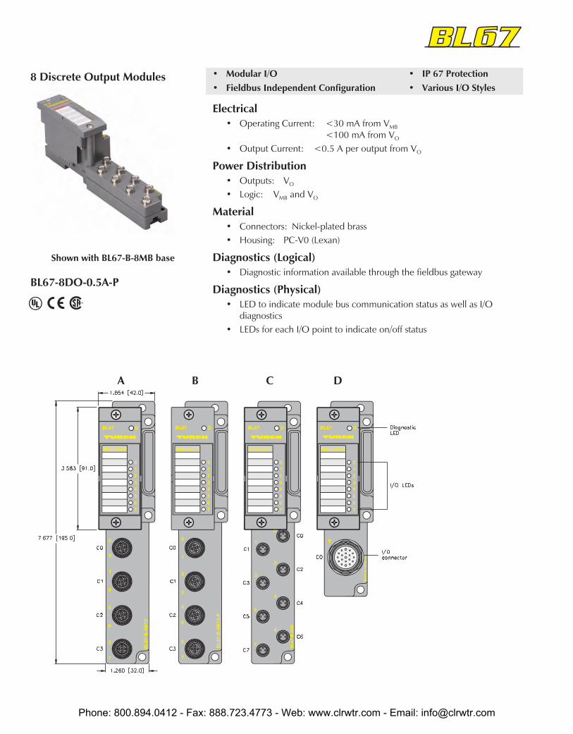
BL67-8DO-0.5A-P
• Modular I/O• Fieldbus Independent Configuration
• IP 67 Protection• Various I/O Styles
Electrical• Operating Current: <30 mA from VMB
<100 mA from VO
• Output Current: <0.5 A per output from VO
Power Distribution• Outputs: VO
• Logic: VMB and VO
Material• Connectors: Nickel-plated brass• Housing: PC-V0 (Lexan)
Diagnostics (Logical)• Diagnostic information available through the fieldbus gateway
Diagnostics (Physical)• LED to indicate module bus communication status as well as I/O
diagnostics• LEDs for each I/O point to indicate on/off status
8 Discrete Output Modules
Shown with BL67-B-8MB base
DA B C
Phone: 800.894.0412 - Fax: 888.723.4773 - Web: www.clrwtr.com - Email: [email protected]

BL67
Part Number Dra
win
g
Out
put
Coun
t
Conn
ecto
rs
Pino
ut
Out
puts
per
Conn
ecto
r
Curr
ent
Styl
e
Indi
vidu
alD
iagn
ostic
s
I/OM
ap
BL67-8DO-0.5A-P with BL67-B-4M12* A 8 0-3 2G 2 0.5 A Source 1
BL67-8DO-0.5A-P with BL67-B-4M12-P* B 8 0-3 2G 2 0.5 A Source 1
BL67-8DO-0.5A-P with BL67-B-8M8* C 8 0-7 PO 1 0.5 A Source 1
BL67-8DO-0.5A-P with BL67-B-1M23 D 8 0 M23-4O 4 0.5 A Source 1
* Base modules sold separately. See page G45.
Outputs Data
Output Connectors
Out
Byte Bit 7 Bit 6 Bit 5 Bit 4 Bit 3 Bit 2 Bit 1 Bit 0
n–1 (Data for modules to the left)
n O-7 O-6 O-5 O-4 O-3 O-2 O-1 O-0
n+1 (Data for modules to the right)
I/O Data Map 1
2G
Mating cordset:RK 4.4T-*-RS 4.4T
Splitter:VBRS 4.4-2RK 4T-*/*
PO
Mating cordset:PSG 3M-*
M23-8O1 = Output0
2 = Output1
3 = Output2
4 = Output3
5 = Output4
6 = Output5
7 = Output6
8 = Output7
9 = VI+10 = VI+11 = VI+12 = V-
Application:TURCK splitter box: 8MB12Z-4PZ-CS12Cable: CSWM CKWM 12-10-*/S101/BL67
Phone: 800.894.0412 - Fax: 888.723.4773 - Web: www.clrwtr.com - Email: [email protected]

BL67-16DO-0.1A-P
• Modular I/O• Fieldbus Independent Configuration
• IP 67 Protection• Valve Bank Module
Electrical• Operating Current: <30 mA from VMB
<100 mA from VO
• Output Current: <0.5 A per output from VO
Power Distribution• Outputs: VO
• Logic: VMB and VO
Material• Connectors: Nickel-plated brass• Housing: PC-V0 (Lexan)
Diagnostics (Logical)• Diagnostic information available through the fieldbus gateway
Diagnostics (Physical)• LED to indicate module bus communication status as well as I/O
diagnostics• LEDs for each I/O point to indicate on/off status
16 Discrete Output Module
Shown with BL67-8-1M23 base
Note: For connection to SMC valve blocks use CSM DB25 19-17-*/SMC (* indicates the length in meters). This cordset connects fromthe BL67 19-pin base to a DB25 connector, and is wired for SMC valve connections.
Phone: 800.894.0412 - Fax: 888.723.4773 - Web: www.clrwtr.com - Email: [email protected]

BL67
Part Number Dra
win
g
Out
put
Coun
t
Conn
ecto
rs
Pino
ut
Out
puts
per
Conn
ecto
r
Curr
ent
Styl
e
Indi
vidu
alD
iagn
ostic
s
I/OM
ap
BL67-16DO-0.1-P with BL67-B-1M23-19 A 16 0 M23-16O 16 0.1 A Source 1
* Base modules sold separately. See page G45.
Outputs Data
Output Connectors
Out
Byte Bit 7 Bit 6 Bit 5 Bit 4 Bit 3 Bit 2 Bit 1 Bit 0
n–1 (Data for modules to the left)
n O-7 O-6 O-5 O-4 O-3 O-2 O-1 O-0
n+1 O-15 O-14 O-13 O-12 O-11 O-10 O-9 O-8
n+2 (Data for modules to the right)
I/O Data Map 1
1 = Output14
2 = Output10
3 = Output6
4 = Output3
5 = Output2
6 = V-7 = Output1
8 = Output5
9 = Output9
10 = Output13
11 = Output12
12 = PE13 = Output11
14 = Output7
15 = Output0
16 = Output4
17 = Output8
18 = Output15
19 = VI+
M23-16O
Applications:• SMC Valve Blocks; CSM DB25 19-17-*/SMC• MAC Valve Blocks; CSM DBK 25 19-17-*/MAC• 16MB12-4P2-CS191; CSM CKM 19-19-0-*/S101* Indicates lenght in meters.1 Splitter box, refer to Connectivity Catalog for more informationNote: TURCK cannot guarantee pinout pinout of connecting devices. Please verify pinout is correct for your application.
Phone: 800.894.0412 - Fax: 888.723.4773 - Web: www.clrwtr.com - Email: [email protected]

BL67-4DI-PD
• Modular I/O• Per Point Diagnostics
• IP 67 Protection• Various I/O Styles
Electrical• Operating Current: <30 mA from VMB
<100 mA from VI
Power Distribution• Inputs: VI
• Logic: VMB and VI
Material• Connectors: Nickel-plated brass• Housing: PC-V0 (Lexan)
Diagnostics (Logical)• Diagnostic information available through the fieldbus gateway
Diagnostics (Physical)• LED to indicate module bus communication status as well as I/O
diagnostics• LEDs for each I/O point to indicate on/off status
Deluxe 4 Discrete Input Module
Shown with BL67-B-4M8 base
DA B C
Phone: 800.894.0412 - Fax: 888.723.4773 - Web: www.clrwtr.com - Email: [email protected]

BL67
Part Number Dra
win
g
Inpu
t Cou
nt
Conn
ecto
rs
Pino
ut
Inpu
tspe
rCo
nnec
tor
Sens
orSt
yle
Indi
vidu
alD
iagn
ostic
sW
ire-B
reak
Det
ectio
n
I/OM
ap
BL67-4DI-PD with BL67-B-4M12* A 4 0-3 S 1 PNP X X 1
BL67-4DI-PD with BL67-B-2M12* B 4 0-1 2S 2 PNP X 1
BL67-4DI-PD with BL67-B-2M12-P* C 4 0-1 2S 2 PNP X 1
BL67-4DI-PD with BL67-B-4M8* D 4 0-3 PI 1 PNP X 1
* Base modules sold separately. See page G45.
Inputs Data
Input Connectors
In
Byte Bit 7 Bit 6 Bit 5 Bit 4 Bit 3 Bit 2 Bit 1 Bit 0
n–1 (Data from modules to the left)
n Data from next discretemodules I-3 I-2 I-1 I-0
n+1 (Data from modules to the right)
I/O Data Map 1
S
Mating cordset:RK 4.4T-*-RS 4.4T
2S
Mating cordset:RK 4.4T-*-RS 4.4T
Splitter:VBRS 4.4-2RK 4T-*/*
PI
Mating cordset:PSG 3M-*
Note: I/O faults can be reported in the I/O map. Consult the product user manual for details.
Phone: 800.894.0412 - Fax: 888.723.4773 - Web: www.clrwtr.com - Email: [email protected]

BL67-8DI-PD
• Modular I/O• Per Point Diagnostics
• IP 67 Protection• Various I/O Styles
Electrical• Operating Current: <30 mA from VMB
<100 mA from VI
Power Distribution• Inputs: VI
• Logic: VMB and VI
Material• Connectors: Nickel-plated brass• Housing: PC-V0 (Lexan)
Diagnostics (Logical)• Diagnostic information available through the fieldbus gateway
Diagnostics (Physical)• LED to indicate module bus communication status as well as I/O
diagnostics• LEDs for each I/O point to indicate on/off status
Deluxe 8 Discrete Input Module
Shown with BL67-B-4M12 base
A B C
Phone: 800.894.0412 - Fax: 888.723.4773 - Web: www.clrwtr.com - Email: [email protected]

BL67
Part Number Dra
win
g
Inpu
t Cou
nt
Conn
ecto
rs
Pino
ut
Inpu
tspe
rCo
nnec
tor
Sens
orSt
yle
Indi
vidu
alD
iagn
ostic
sW
ire-B
reak
Det
ectio
n
I/OM
ap
BL67-8DI-PD with BL67-B-4M12* A 8 0-3 2S 2 PNP X X 1
BL67-8DI-PD with BL67-B-4M12-P* B 8 0-3 2S 2 PNP X 1
BL67-8DI-PD with BL67-B-8M8* C 8 0-7 PI 1 PNP X 1
*Note: Base modules sold separately. See page G45.
Inputs Data
Input Connectors
In
Byte Bit 7 Bit 6 Bit 5 Bit 4 Bit 3 Bit 2 Bit 1 Bit 0
n–1 (Data from modules to the left)
n I-7 I-6 I-5 I-4 I-3 I-2 I-1 I-0
n+1 (Data from modules to the right)
I/O Data Map 1
PI
Mating cordset:PSG 3M-*
2S
Mating cordset:RK 4.4T-*-RS 4.4T
Splitter:VBRS 4.4-2RK 4T-*/*
Note: Pins 1 & 2 must be jumpered togetherfor open circuit monitoring.
Note: I/O faults can be reported in the I/O table. Consult the product user manual for details.
Phone: 800.894.0412 - Fax: 888.723.4773 - Web: www.clrwtr.com - Email: [email protected]

BL67-8XSG-PD
• Modular I/O• Fieldbus Independent Configuration
• IP 67 Protection• Various I/O Styles
Discrete Input/Output Module
Shown with BL67-B-4M12 base
A C
Electrical• Operating Current: <30 mA from VMB
<100 mA from VO
• Output Current: <0.5 A per output from VO
Power Distribution• Inputs: VI
• Outputs: VO
• Logic: VMB and VO
Material• Connectors: Nickel-plated brass• Housing: PC-V0 (Lexan)
Diagnostics (Logical)• Diagnostic information available through the fieldbus gateway
Diagnostics (Physical)• LED to indicate module bus communication status as well as I/O
diagnostics• LEDs for each I/O point to indicate on/off status
B
Phone: 800.894.0412 - Fax: 888.723.4773 - Web: www.clrwtr.com - Email: [email protected]

BL67
Part Number Dra
win
gIn
put C
ount
Conn
ecto
rsPi
nout
Inpu
tspe
rCo
nnec
tor
Sens
orSt
yle
VI+
Avai
labl
eCu
rren
tIn
divi
dual
Dia
gnos
tics
Wire
-Bre
akD
etec
tion
Out
put
Coun
tCo
nnec
tors
Pino
utO
utpu
tspe
rCo
nnec
tor
Curr
ent
Indi
vidu
alD
iagn
ostic
sW
ire-B
reak
Det
ectio
nI/O
Map
BL67-8XSG-PDwith BL67-B-4M12* A 8 0-3 2X 2 PNP X 8 0-3 2X 2 0.5 A X 1
BL67-8XSG-PDwith BL67-B-8M8* B 8 0-7 PI 1 PNP X 8 0-7 PO 1 0.5 A X 1
BL67-8XSG-PDwith BL67-B-1M23 C 8 0 M23 8 PNP 80 mA
each 8 0 M23 8 0.5 A X 1
BL67-8XSG-PDwith BL67-B-1M23-VI* C 8 0 M23 8 PNP 4 A
total 8 0 M23 8 0.5 A X 1
* Base modules sold separately. See page G45.
Inputs Outputs Data
Input/Output Connectors
In
Byte Bit 7 Bit 6 Bit 5 Bit 4 Bit 3 Bit 2 Bit 1 Bit 0
n–1 (Data from modules to the left)
n I-7 I-6 I-5 I-4 I-3 I-2 I-1 I-0
n+1 (Data from modules to the right)
Out
n–1 (Data for modules to the left)
n O-7 O-6 O-5 O-4 O-3 O-2 O-1 O-0
n+1 (Data for modules to the right)
I/O Data Map 1
2X
Mating cordset:RK 4.4T-*-RS 4.4T
Splitter:VBRS 4.4-2RK 4T-*/*
PI
Mating cordset:PSG 3M-*
Note: I/O faults can be reported in the I/O table. Consult the product user manual for details.
M231 = Output0
2 = Output1
3 = Output2
4 = Output3
5 = Output4
6 = Output5
7 = Output6
8 = Output7
9 = VI+10 = VI+11 = VI+12 = V-
Application:TURCK splitter box: 8MB12Z-4PZ-CS12Cable: CSWM CKWM 12-10-*/S101/BL67
Phone: 800.894.0412 - Fax: 888.723.4773 - Web: www.clrwtr.com - Email: [email protected]

BL67-4DI4DO-PD
• Modular I/O• Per Point Diagnostics
• IP 67 Protection• Various I/O Styles
Electrical• Operating Current: <30 mA from VMB
<100 mA from VO
• Output Current: <0.5 A per channel from VO
Power Distribution• Inputs: VI
• Outputs: VO
• Logic: VMB and VO
Material• Connectors: Nickel-plated brass• Housing: PC-V0 (Lexan)
Diagnostics (Logical)• Diagnostic information available through the fieldbus gateway
Diagnostics (Physical)• LED to indicate module bus communication status as well as I/O
diagnostics• LEDs for each I/O point to indicate on/off status
Deluxe 4 Discrete Input4 Discrete Output Module
Shown with BL67-B-4M12 base
A B DC
Phone: 800.894.0412 - Fax: 888.723.4773 - Web: www.clrwtr.com - Email: [email protected]

BL67
Part Number Dra
win
g#
Inpu
t Cou
ntCo
nnec
tors
Pino
utIn
puts
per
Conn
ecto
rSe
nsor
Styl
eVI
+Av
aila
ble
Curr
ent
Gro
upD
iagn
ostic
sIn
divi
dual
Wire
-Bre
akD
etec
tion
Out
put
Coun
tCo
nnec
tors
Pino
ut
Out
puts
per
Conn
ecto
rCu
rren
t
Indi
vidu
alD
iagn
ostic
sW
ire-B
reak
I/OM
ap
BL67-4DI4DO-PDwithBL67-B-4M12-P*
A 4 0-1 2S 2 PNP X 4 2-3 2G 2 0.5 A X 1
BL67-4DI4DO-PDwith BL67-B-4M12* B 4 0-3 C 1 PNP X 4 0-3 C 1 0.5 A X 1
BL67-4DI4DO-PDwith BL67-B-8M8* C 4 0-3 PI 1 PNP X 4 4-7 PO 1 0.5 A X 1
BL67-4DI4DO-PDwith BL67-B-1M23* D 4 0 M23 4 PNP 80 mA
each 4 0 M23 4 0.5 A 1
BL67-4DI4DO-PDwith BL67-B-1M23* D 4 0 M23 4 PNP 4 A
total 4 0 M23 4 0.5 A 1
* Base modules sold separately. See page G45.
Inputs Outputs Data
Input/Output Connectors
In
Byte Bit 7 Bit 6 Bit 5 Bit 4 Bit 3 Bit 2 Bit 1 Bit 0
n–1 (Data from modules to the left)
n Data from next discretemodules I-3 I-2 I-1 I-0
n+1 (Data from modules to the right)
Out
n–1 (Data for modules to the left)
n (Data for next discretemodules) O-3 O-2 O-1 O-0
n+1 (Data for modules to the right)
I/O Data Map 1
PI
Mating cordset:PSG 3M-*
2S
Mating cordset:RK 4.4T-*-RS 4.4T
Splitter:VBRS 4.4-2RK 4T-*/*
2G
Mating cordset:RK 4.4T-*-RS 4.4T
Splitter:VBRS 4.4-2RK 4T-*/*
C
Mating cordset:RK 4.4T-*-RS 4.4T
Splitter:VB2-RS 4.4T-1/2RK 4.4T-*/*/S651
Note: I/O faults can be reported in the I/O table. Consult the productuser manual for details.
M231 = Input0
2 = Input1
3 = Input2
4 = Input3
5 = Output0
6 = Output1
7 = Output2
8 = Output3
9 = VI+10 = VI+11 = VI+12 = V-
Phone: 800.894.0412 - Fax: 888.723.4773 - Web: www.clrwtr.com - Email: [email protected]

BL67-1CVI
• Modular I/O• Fieldbus Independent Configuration
• IP 67 Protection• Various I/O Styles
Electrical• Operating Current: <30 mA from VMB (SSI)
<50 mA from V (all)<100 mA from V supply
Power Distribution• I/O: VI• Logic: VMB and VI
Material• Connectors: Nickel-plated brass• Housing: PC-V0 (Lexan)
Diagnostics (Logical)• Diagnostic information available through the fieldbus gateway
Diagnostics (Physical)• LED to indicate module bus communication status as well as I/O
diagnostics• LEDs for each I/O point to indicate on/off status
Functional Description• Connect up to 8 CANopen slaves to this module• Map the slaves into any available fieldbus
CANopen Interface Module
Phone: 800.894.0412 - Fax: 888.723.4773 - Web: www.clrwtr.com - Email: [email protected]

BL67
Part Number Dra
win
g
Slav
es
Conn
ecto
rs
Pino
ut
Byte
s/Sl
ave
Max
. Bau
dRa
te
Gro
upD
iagn
ostic
s
I/OM
ap
BL67-1CVI with BL67-B-1M12 A 8 0 2S 1 1 mbits/S X 1
* Base modules sold separately. See page G45.
Input Connectors
In
Byte Bit 7 Bit 6 Bit 5 Bit 4 Bit 3 Bit 2 Bit 1 Bit 0
1 Slave 2 Slave 1
2 Slave 4 Slave 3
3 Slave 6 Slave 5
4 Slave 7 Slave 8
Out
5 Slave 2 Slave 1
6 Slave 4 Slave 3
7 Slave 6 Slave 5
8 Slave 7 Slave 8
I/O Data Map 1
Inputs Data
2S
Mating cordset:RK 4.4T-*-RS 4.4T
Splitter:VBRS 4.4-2RK 4T-*/*
Phone: 800.894.0412 - Fax: 888.723.4773 - Web: www.clrwtr.com - Email: [email protected]

BL67-1RS485/422BL67-1RS232BL67-1SSI
• Modular I/O• Fieldbus Independent Configuration
• IP 67 Protection• Various I/O Styles
Electrical• Operating Current: <140 mA from VMB (RS232)
<60 mA from VMB (RS485/422)<50 mA from VMB (SSI)<50 mA from V (all)
Power Distribution• I/O: V• Logic: VMB and V
Material• Connectors: Nickel-plated brass• Housing: PC-V0 (Lexan)
Diagnostics (Logical)• Diagnostic information available through the fieldbus gateway
Diagnostics (Physical)• LED to indicate module bus communication status as well as I/O
diagnostics• LEDs for each I/O point to indicate on/off status
Serial Communication Modules
A B C
Phone: 800.894.0412 - Fax: 888.723.4773 - Web: www.clrwtr.com - Email: [email protected]

BL67
Part Number Dra
win
gIn
put C
ount
Conn
ecto
rsPi
nout
Inpu
tspe
rCo
nnec
tor
Sens
orSt
yle
Gro
upD
iagn
ostic
sO
utpu
tCo
unt
Conn
ecto
rs
Pino
ut
Out
puts
per
Conn
ecto
r
I/OM
ap
BL67-1RS485/422 withBL67-B-1M12* A 1 0 B4 1 RS 485/422 X 1 0 B4 1 1
BL67-1RS485/422 withBL67-B-1M12-8* B 1 0 B4-8 1 RS 485/422 X 1 0 B4-8 1 1
BL67-1RS232 withBL67-B-1M12* A 1 0 B2 1 RS 232 X 1 0 B2 1 1
BL67-1RS232 withBL67-B-1M12-8* B 1 0 B2-8 1 RS 232 X 1 0 B2-8 1 1
BL67-1SSI withBL67-B-1M23* C 1 0 SSI-23 1 SSI X 1 0 SSI-23 1 2
BL67-1SSI withBL67-B-1M12-8* B 1 0 SSI 1 SSI X 1 0 SSI 1 2
* Base modules sold separately. See page G45.
Inputs Outputs Data
Input/Output ConnectorsPinouts are shown on following page.
In
Byte Bit 7 Bit 6 Bit 5 Bit 4 Bit 3 Bit 2 Bit 1 Bit 0
n–1 (Data from modules to the left)
n STOP X X ERRPARA UFLW OFLW ERR
SSISSIDIAG
n+1 UP DN RELCMP2
FLAGCMP2
STSCMP2
RELCMP1
FLAGCMP1
STSCMP1
n+2 REG WRACPT
REG WRACK X X SSI
STS3SSISTS2
SSISTS 1
SSISTS0
n+3 REG RDABRT X REG_RD_ADR
n+4 REG_RD_DATA, Byte 0
n+5 REG_RD_DATA, Byte 1
n+6 REG_RD_DATA, Byte 2
n+7 REG_RD_DATA, Byte 3
n+8 (Data from modules to the right)
Out
–1 (Data for modules to the left)
n STOP X X X X X X X
n+1 X X X CLRCMP2
ENCMP2 X CLR
CMP1ENCMP1
n+2 REG WR X REG_WR_ADR
n+3 X X REG_RD_ADR
n+4 REG_WR_DATA, Byte 0
n+5 REG_WR_DATA, Byte 1
n+6 REG_WR_DATA, Byte 2
n+7 REG_WR_DATA, Byte 3
n+8 (Data for modules to the right)
I/O Data Map 2
In
Byte Bit 7 Bit 6 Bit 5 Bit 4 Bit 3 Bit 2 Bit 1 Bit 0
n–1 (Data from modules to the left)
n Data Byte 5 (MSB)
n+1 Data Byte 4
n+2 Data Byte 3
n+3 Data Byte 2
n+4 Data Byte 1
n+5 Data Byte 0 (LSB)
n+6 BufOvfl
FrameErr
HndShErr
HWFailure
PrmErr Reserved
n+7 STAT TX_CNT_ACK
RX_CNT RX_BYTE_CNT
n+8 (Data from modules to the right)
Out
n–1 (Data for modules to the left)
n Data Byte 5 (MSB)
n+1 Data Byte 4
n+2 Data Byte 3
n+3 Data Byte 2
n+4 Data Byte 1
n+5 Data Byte 0 (LSB)
n+6 Reserved RxBufFlush
TxBufFlush
n+7 STATRes
RX_CNT_ACK
TX_CNT TX_BYTE_CNT
n+8 (Data for modules to the right)
I/O Data Map 1
Phone: 800.894.0412 - Fax: 888.723.4773 - Web: www.clrwtr.com - Email: [email protected]

SSI-23
1 = V-2 = VI+3 = CLK+4 = CLK-5 = DATA+6 = DATA-
7 = NC8 = Shield9 = NC10 = NC11 = NC12 = NC
B4
1 = Tx2 = Tx+3 = Rx-4 = Rx+5 = Shield
SSI
1 = V-2 = VI+3 = CLK+4 = CLK-
5 = DATA+6 = DATA-7 = NC8 = Shield
B4-8
1 = Rx+2 = Tx+3 = Tx-4 = NC
5 = Rx-6 = GndISO
7 = NC5 = Shield
B2
1 = NC2 = TxD3 = GndISO
4 = RxD5 = Shield
B2-8
1 = RxD2 = TxD3 = RTS4 = CTS
5 = GndISO
6 = NC7 = NC5 = Shield
Phone: 800.894.0412 - Fax: 888.723.4773 - Web: www.clrwtr.com - Email: [email protected]

BL67-2AI-VBL67-2AI-IBL67-4AI-V/I
• Modular I/O• Fieldbus Independent Configuration
• IP 67 Protection• Various I/O Styles
Electrical• Operating Current: <35 mA from VMB
<12 mA from V
Power Distribution• Inputs: VI
• Logic: VMB and VI
Material• Connectors: Nickel-plated brass• Housing: PC-V0 (Lexan)
Diagnostics (Logical)• Diagnostic information available through the fieldbus gateway
Diagnostics (Physical)• LED to indicate module bus communication status as well as I/O
diagnostics• LEDs for each I/O point to indicate on/off status
2 Analog Input Modules
BL67-4AI-V/I
Phone: 800.894.0412 - Fax: 888.723.4773 - Web: www.clrwtr.com - Email: [email protected]

BL67
Part Number Inpu
t Cou
nt
Conn
ecto
rs
Pino
ut
Inpu
tspe
rCo
nnec
tor
Sens
orSt
yle
Gro
upD
iagn
ostic
sIn
divi
dual
Dia
gnos
tics
Wire
-Bre
akD
etec
tion
I/OM
ap
BL67-2AI-V with BL67-B-2M12* 2 0-1 B-AI 1 -10/0 to 10 V 1
BL67-2AI-I with BL67-B-2M12* 2 0-1 B-AI 1 0/4 to 20 mA 1
BL67-4AI-V/I with BL67-B-4M12* 4 0-3 B-AI 1 -10/0 to 10 V0/4 to 20 mA 2
* Base modules sold separately. See page G45.
Inputs Data
Input Connectors
B-AI
Mating cordset:Isolated Loop: RK 4.5T-*M-RS 4.5T/S653Loop Powered: RK 4.5T-*M-RS 4.5T/LPS/S653
Applications:TURCK Sensors: LU; RK 4.4T-*-RS 4.4T/S1118
LI; RK 4.4T-*-*RS 4.4T/S1120
In
Byte Bit 7 Bit 6 Bit 5 Bit 4 Bit 3 Bit 2 Bit 1 Bit 0
n–1 (Data from modules to the left)
n Channel 0, LSB
n+1 Channel 0, MSB
n+2 Channel 1, LSB
n+3 Channel 1, MSB
n+4 Channel 2, LSB
n+5 Channel 2, MSB
n+6 Channel 3, LSB
n+7 Channel 3, MSB
n+8 (Data from modules to the right)
I/O Data Map 1
Phone: 800.894.0412 - Fax: 888.723.4773 - Web: www.clrwtr.com - Email: [email protected]

BL67-2AI-TCBL67-2AI-PT
• Modular I/O• Thermocouple or RTD Inputs
• IP 67 Protection• Various I/O Styles
Electrical• Operating Current: <35 mA from VMB (TC)
<45 mA from VMB (PT)<30 mA from V (all)
Power Distribution• Inputs: VI
• Logic: VMB and VI
• Thermocouple Types: B, E, J, K, N, R, S and T (TC)• RTD Types: PT100, PT200, PT500, PT1000, Ni100, Ni1000 (PT)
Material• Connectors: Nickel-plated brass• Housing: PC-V0 (Lexan)
Diagnostics (Logical)• Diagnostic information available through the fieldbus gateway
Diagnostics (Physical)• LED to indicate module bus communication status as well as I/O
diagnostics• LEDs for each I/O point to indicate on/off status
2 Temperature Input Modules
Phone: 800.894.0412 - Fax: 888.723.4773 - Web: www.clrwtr.com - Email: [email protected]

BL67
Part Number Inpu
t Cou
nt
Conn
ecto
rs
Pino
ut
Inpu
tspe
rCo
nnec
tor
Sens
orSt
yle
Gro
upD
iagn
ostic
sIn
divi
dual
Dia
gnos
tics
Wire
-Bre
akD
etec
tion
I/OM
ap
BL67-2AI-TC with BL67-B-2M12* 2 0-1 TC 1 TC 1
BL67-2AI-PT with BL67-B-2M12* 2 0-1 RTD 1 RTD 1
* Base modules sold separately. See page G45.
Inputs Data
Input Connectors
In
Byte Bit 7 Bit 6 Bit 5 Bit 4 Bit 3 Bit 2 Bit 1 Bit 0
n–1 (Data from modules to the left)
n Channel 0, LSB
n+1 Channel 0, MSB
n+2 Channel 1, LSB
n+3 Channel 1, MSB
n+4 (Data from modules to the right)
I/O Data Map 1
TC
Mating Connector(field wireable):
WAS5-THERMO (includes coldjunction compensation)
Isolated Loop: RK 4.5T-*M-RS 4.5T/S653Loop Powered: RK 4.5T-*M-RS 4.5T/LPS/S653
RTD
Mating cordset:RK 4.5T-*-RS 4.5TIsolated Loop: RK 4.5T-*M-RS 4.5T/S653Loop Powered: RK 4.5T-*M-RS 4.5T/LPS/S653
Phone: 800.894.0412 - Fax: 888.723.4773 - Web: www.clrwtr.com - Email: [email protected]
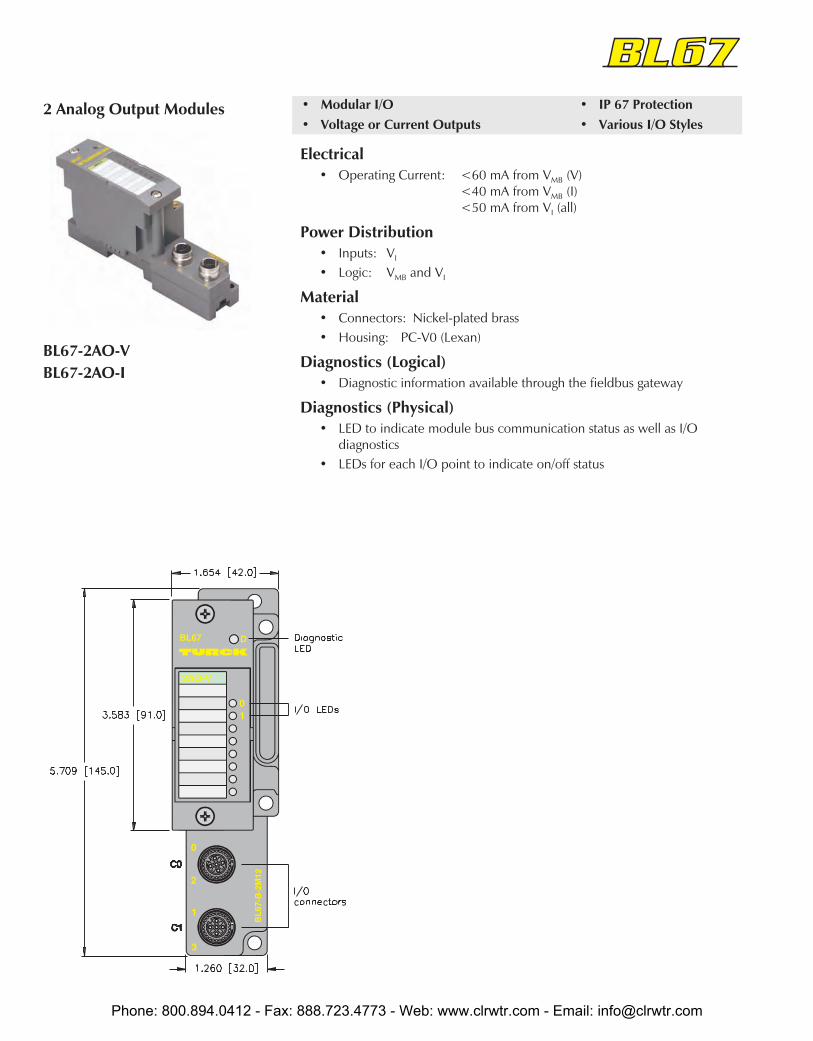
BL67-2AO-VBL67-2AO-I
• Modular I/O• Voltage or Current Outputs
• IP 67 Protection• Various I/O Styles
Electrical• Operating Current: <60 mA from VMB (V)
<40 mA from VMB (I)<50 mA from VI (all)
Power Distribution• Inputs: VI
• Logic: VMB and VI
Material• Connectors: Nickel-plated brass• Housing: PC-V0 (Lexan)
Diagnostics (Logical)• Diagnostic information available through the fieldbus gateway
Diagnostics (Physical)• LED to indicate module bus communication status as well as I/O
diagnostics• LEDs for each I/O point to indicate on/off status
2 Analog Output Modules
Phone: 800.894.0412 - Fax: 888.723.4773 - Web: www.clrwtr.com - Email: [email protected]

BL67
Part Number Out
put
Coun
t
Conn
ecto
rs
Pino
ut
Out
puts
per
Conn
ecto
r
Type
Indi
vidu
alD
iagn
ostic
s
Wire
-Bre
akD
etec
tion
I/OM
ap
BL67-2AO-V with BL67-B-2M12* 2 0-1 B-AOV 1 -10/0 to 10V 1
BL67-2AO-I with BL67-B-2M12* 2 0-1 B-AOI 1 0/4 to 20 mA 1
* Base modules sold separately. See page G45.
Outputs Data
Output Connectors
Out
Byte Bit 7 Bit 6 Bit 5 Bit 4 Bit 3 Bit 2 Bit 1 Bit 0
n–1 (Data for modules to the left)
n Channel 0, LSB
n+1 Channel 0, MSB
n+2 Channel 1, LSB
n+3 Channel 1, MSB
n+4 (Data for modules to the right)
I/O Data Map 1
B-AOV
Mating cordset:RK 4.5T-*-RS 4.5T
B-AOI
Mating cordset:RK 4.5T-*-RS 4.5T
Phone: 800.894.0412 - Fax: 888.723.4773 - Web: www.clrwtr.com - Email: [email protected]

BL67-PF-24VDC
• Modular I/O• Isolate Power Segments
• IP 67 Protection• Various I/O Styles
Electrical• Operating Current: <30 mA from VMB
• Output Current: <10 A for downstream I/O
Power Distribution• Accepts 24 VDC supply to provide VI and VO for downstream
modules
Material• Connectors: Nickel-plated brass• Housing: PC-V0 (Lexan)
Diagnostics (Logical)• Diagnostic information available through the fieldbus gateway
Diagnostics (Physical)• LED to indicate module bus communication status as well as I/O
diagnostics• LEDs to indicate power supply status
Power Feeding Module
Phone: 800.894.0412 - Fax: 888.723.4773 - Web: www.clrwtr.com - Email: [email protected]

BL67
Male
4-Pin
minifast Pinouts
When used with BL67-B-1RSM-4 base module
Male
5-Pin
minifast Pinouts
When used with BL67-B-1RSM base module
1 = VO, VI
2 = NC3 = NC4 = Gnd
1 = Gnd2 = Gnd3 = PE4 = VI
5 = VO
Phone: 800.894.0412 - Fax: 888.723.4773 - Web: www.clrwtr.com - Email: [email protected]

Base Modules for BL67 I/O
Style Part Number Description
Two eurofast ® Connectors BL67-B-2M12 Base module with two eurofast connectors. When usedwith 4 input or 4 output modules each connector has 2 I/Opoints.
Two eurofast Connectors with Paired I/O BL67-B-2M12-P Base module with two eurofast connectors. Each connectorhas 2 I/O points, paired so consecutive points are on thesame connector.
Four eurofast Connectors BL67-B-4M12 Base module with four eurofast connectors. When usedwith 8 input or 8 output modules each connector has 2 I/Opoints.
Four eurofast Connectors with Paired I/O BL67-B-4M12-P Base module with four eurofast connectors. Each connectorhas 2 I/O points, paired so consecutive points are on thesame connector.
Phone: 800.894.0412 - Fax: 888.723.4773 - Web: www.clrwtr.com - Email: [email protected]

BL67
Base Modules for BL67 I/O
Style Part Number Description
One eurofast ® Connector (5-pin) BL67-B-1M12 Base module with one eurofast 5-pin connector. Typicallyused with serial I/O modules.
One eurofast Connector (8-pin) BL67-B-1M12-8 Base module with one eurofast 8-pin connector. Typicallyused with serial I/O modules.
Four picofast ® Connectors BL67-B-4M8 Base module with four picofast connectors. Typically usedwith 4-input or 4-output modules.
Eight picofast Connectors BL67-B-8M8 Base module with eight picofast connectors. Typically usedwith 8-input or 8-output modules.
Phone: 800.894.0412 - Fax: 888.723.4773 - Web: www.clrwtr.com - Email: [email protected]

Base Modules for BL67 I/O
Style Part Number Description
One M23 Connector (12-pin) BL67-B-1M23 Base module with one 12-pin M23 connector. Typicallyused with 8-output or SSI modules.
BL67-B-1M23-VI Base module that allows full 4 A available from V+ pins.
One M23 Connector (19-pin) BL67-B-1M23-19 Base module with one 19-pin M23 connector. For use withthe 16-output module.
One minifast® Connector (5-pin) BL67-B-1RSM Base module with one 5-pin minifast connector. For usewith the power feeding module, five wire power scheme.
One minifast Connector (4-pin) BL67-B-1RSM-4 Base module with one 4-pin minifast connector. For usewith the power feeding module, four wire power scheme.
Phone: 800.894.0412 - Fax: 888.723.4773 - Web: www.clrwtr.com - Email: [email protected]

BL67
Part Number Description
Labels for labeling electronic modules BL67-Label/DIN-A4-50-PCS DIN A4 sheet size
Programming Cable - For connecting the BL20/BL67 system tothe I/O Assistant software
XN-PS2-CABLE
Phone: 800.894.0412 - Fax: 888.723.4773 - Web: www.clrwtr.com - Email: [email protected]