riilv6.2 it business management operation guide
TRANSCRIPT
[RIIL IT Business Management Operation Guide]
Page 1
RIIL IT Business ManagementOperation Guide
Ruijie Networks Co., Ltd.
11th Floor, Tower A, East Wing, ZhongYiPengAo Plaza, No.29 Fuxing Road, Haidian District, Beijing,China
Postal code: 100036
Customer service hotline: 4008111000
Online consultation: http://webchat.ruijie.com.cn

[RIIL IT Business Management Operation Guide]
Page 2
Copyright StatementCopyright by Ruijie Networks Co., Ltd. All rights reserved. All rights in the content of this document andthis copyright statement are owned by Ruijie Networks Co., Ltd.
No part of this document may be reproduced, extracted, backed up, modified, transmitted, translatedinto other languages, or put into commercial use in any form or by any means without prior writtenconsent of Ruijie Networks Co., Ltd.

[RIIL IT Business Management Operation Guide]
Page 3
DisclaimerThis document is prepared based on existing information. The information in this document is subjectto change without notice. Please visit the official website of Ruijie Networks for the most currentinformation. Although every effort has been made in the preparation of this document to ensure thatthis document is accurate, no guarantee is being made or implied.
[RIIL IT Business Management Operation Guide]
Page 4
Table Of Contents
Copyright Statement ........................................................................................................................................ 2
Disclaimer ....................................................................................................................................................... 3
Table Of Contents ............................................................................................................................................ 4
1 Introduction ................................................................................................................................................. 7
2 Logging in to RIIL ........................................................................................................................................ 7
3 Quick Start ................................................................................................................................................... 8
3.1 Configuration Wizard ...................................................................................................................... 8
3.1.1 Domain Management ........................................................................................................... 9
3.1.2 Department Management................................................................................................... 12
3.1.3 Role Management ................................................................................................................ 13
3.1.4 User Management ............................................................................................................... 15
3.1.5 Resource Policy ................................................................................................................... 19
3.1.6 Topology Discovery ............................................................................................................. 25
3.1.7 Resource Management ....................................................................................................... 28
3.1.8 Resource Group Management ............................................................................................ 31
3.1.9 Workgroup Management ................................................................................................... 32
3.1.10 Alarm Rule ......................................................................................................................... 32
3.1.11 Mail Server Setting ............................................................................................................ 35
3.1.12 Short Message Server Setting........................................................................................... 36
4 Functional Details ...................................................................................................................................... 37
4.1 System Management...................................................................................................................... 37
4.1.1 Staff Organization ................................................................................................................ 37
4.1.2 Domain Management ......................................................................................................... 45
4.1.3 Resource Discovery & Configuration ................................................................................. 45
4.1.4 Monitoring Configuration................................................................................................... 48
4.1.5 System Configuration ......................................................................................................... 57
4.2 Homepage ...................................................................................................................................... 66
4.3 IT Health Index ............................................................................................................................... 68
4.3.1 Health Index Setting ............................................................................................................ 68
4.3.2 Warning Threshold Setting ................................................................................................. 69
4.3.3 Health Index Analysis .......................................................................................................... 69
4.4 Business Service ............................................................................................................................ 71
[RIIL IT Business Management Operation Guide]
Page 5
4.4.1 Overall Business Services ................................................................................................... 71
4.4.2 Business Application Analysis ........................................................................................... 82
4.4.3 Overall Events and Alarms .................................................................................................. 83
4.4.4 Policy Configuration ........................................................................................................... 87
4.5 Event and Alarm Center ................................................................................................................. 91
4.5.1 Event Console ...................................................................................................................... 91
4.5.2 Alarm Console ...................................................................................................................... 94
4.6 Resource Management .................................................................................................................. 96
4.6.1 Resource Monitoring .......................................................................................................... 96
4.6.2 Script Monitoring ................................................................................................................ 98
4.6.3 Log Monitoring .................................................................................................................... 98
4.6.4 Automatic Inspection .......................................................................................................... 99
4.6.5 Real-time Data Analysis .................................................................................................... 102
4.6.6 TOPN .................................................................................................................................. 105
4.7 Network Topology ........................................................................................................................ 106
4.7.1 Access Conditions and Display ......................................................................................... 106
4.7.2 GUI ..................................................................................................................................... 107
4.7.3 Statistics Area .................................................................................................................... 108
4.7.4 Operation Toolbar ............................................................................................................. 108
4.7.5 Navigation ......................................................................................................................... 110
4.7.6 Layout Types ..................................................................................................................... 111
4.7.7 Marquee ............................................................................................................................. 114
4.7.8 Topology Area .................................................................................................................... 114
4.7.9 Shortcut Button Area ........................................................................................................ 136
4.7.10 Topology Switching ......................................................................................................... 152
4.7.11 Resource Panel ................................................................................................................ 155
4.8 Traffic Analysis ............................................................................................................................. 159
4.8.1 Flow Topology .................................................................................................................... 159
4.8.2 Interface Traffic Overview ................................................................................................ 175
4.8.3 TOPN .................................................................................................................................. 178
4.8.4 Traffic Analysis Overview ................................................................................................. 182
4.8.5 Management Configuration.............................................................................................. 200
4.9 KPI & Statistics Reports ................................................................................................................ 203
4.9.1 Resource Reports .............................................................................................................. 203
4.9.2 Analysis Reports ................................................................................................................ 205

[RIIL IT Business Management Operation Guide]
Page 6
4.9.3 Trend Reports .................................................................................................................... 207
4.9.4 Top N Reports .................................................................................................................... 209
4.9.5 Fault Reports ..................................................................................................................... 210
4.9.6 Resource Analysis Reports ............................................................................................... 212
4.9.7 My Feeds ............................................................................................................................ 214
4.10 CMDB .......................................................................................................................................... 214
4.10.1 Configuration Overview ................................................................................................. 214
4.10.2 Auditing CIs ..................................................................................................................... 220
4.10.3 Configuration Wizard ..................................................................................................... 225
4.11 Knowledge Base ......................................................................................................................... 228
4.11.1 My Knowledge ................................................................................................................. 228
4.11.2 Knowledge Management ................................................................................................ 233
4.12 Wireless Management ............................................................................................................... 236
4.12.1 Homepage ....................................................................................................................... 236
4.12.2 Wireless Topology ........................................................................................................... 244
4.12.3 Overall Events and Alarms .............................................................................................. 255
4.12.4 Wireless Resource Management .................................................................................... 260
4.12.5 TOP N ............................................................................................................................... 277
4.12.6 Security Management ..................................................................................................... 283
4.12.7 Statistics Reports ............................................................................................................. 284
4.12.8 Wireless Configuration ................................................................................................... 292
5 Appendix ................................................................................................................................................. 316
[RIIL IT Business Management Operation Guide]
Page 7
1 Introduction
Based on the IT service management concept of the IT Infrastructure Library (ITIL), RIIL IT BusinessManagement (hereinafter referred to as RIIL) is developed by Ruijie Networks for the IT support andmanagement departments of large- and medium-sized enterprises by integrating multiple technologiessuch as business services, resource management, and configuration management database (CMDB).RIIL aims to help users solve problems in the IT support and management process and improve the ITservice level and efficiency.
RIIL6.2 is added with the data center, wireless management, and traffic analysis functional modules.
Data center
3D modeling, making management more refined and accurate and allowing you to know everydetail of the data center;
Added statistics of free space and energy consumption, allowing IT managers to make detailedstatistical planning;
Visualized management of devices, presenting every detail of each device precisely.
Wireless management
Visual wireless heat map and intelligent calculation of signal attenuation by obstacles, giving anauthentic reflection of wireless coverage;
Unified management of wireless clients;
Wizard-based configuration, simplifying wireless deployment;
Multidimensional statistical report on wireless resources, giving an intuitive presentation ofresource operations.
Traffic analysis
Support of multiple traffic analysis protocols and mainstream traffic analyzers at markets;
Traffic topology, giving a hierarchical presentation of network traffic occupied by each link;
Traffic usage analysis in the interface, application, terminal, session, and IP address dimensionsand provision of various types of reports.
2 Logging in to RIIL
1. After you install and start RIIL successfully, start a browser and enter http://[server IPaddress]:[port number] in the address bar. The default port is 80. You can leave it blank.
2. The RIIL login page is displayed. You can use the default administrator account (user name:admin; password: riiladmin) to log in to RIIL.

[RIIL IT Business Management Operation Guide]
Page 8
1) Change the password immediately after you log in for the first time.
2) If the Flash Player is not installed on your browser, the following page is displayed,prompting you to install the Flash Player.
3) Although you may download the Flash Player from the local server, you are advised todownload the latest Flash Player version from the official website of Adobe. After you installthe Flash Player, re-start the browser and log in to RIIL.
3 Quick Start
3.1 Configuration Wizard
After you log in to RIIL for the first time, the RIIL Configuration Wizard page is displayed, whichguides you through basic configurations in 12 steps quickly.

[RIIL IT Business Management Operation Guide]
Page 9
When you complete the configuration in each step, click Next to start configuration in the next stepuntil all configurations are finished. The following sections describe the specific operations in eachstep.
3.1.1 Domain Management
Concept of a domain: A domain is equivalent to a management unit, which is applicable in groups thathave subsidiaries and need to manage their subsidiaries in a unified manner. A domain is a collectionof resources and staff, which is available only in the RIIL Enterprise Edition. Users of the RIIL StandardEdition can skip this section and other domain-related sections.
Objective of a domain: To group resources and users based on domains, thereby facilitating distributedmanagement and clarifying permission management.
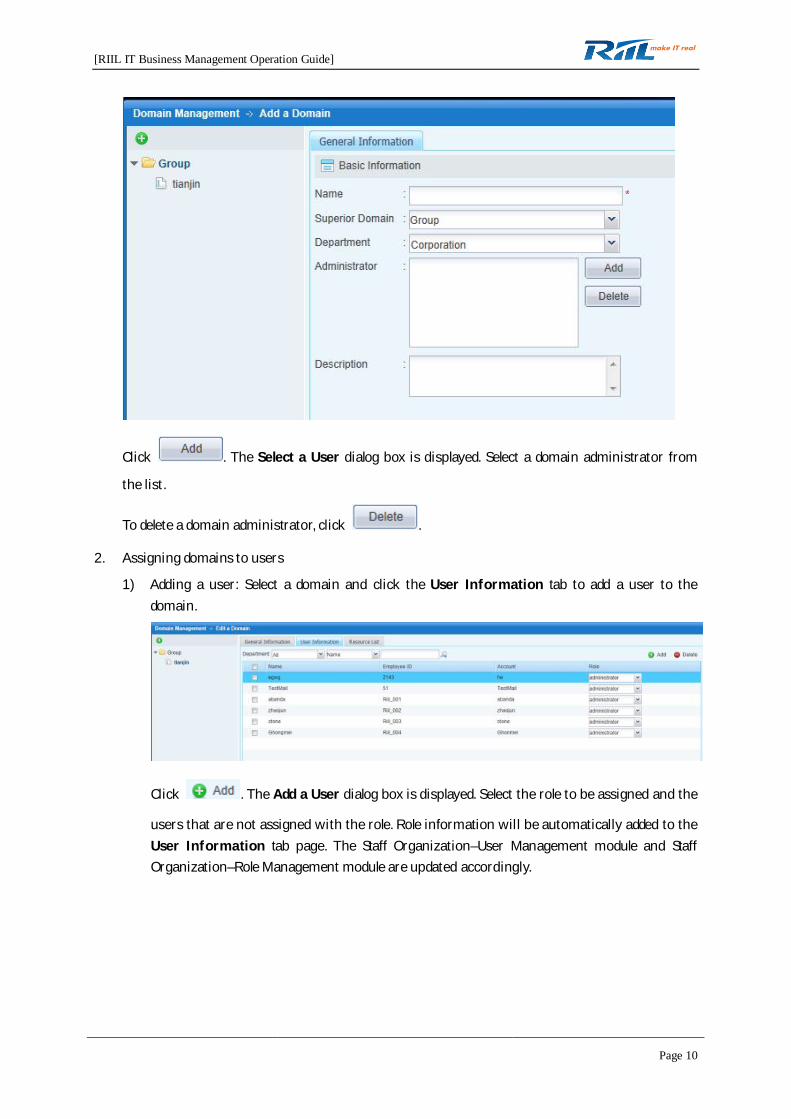
1. Creating a domain
Click . The Domain Management -> Add a Domain page is displayed. On the GeneralInformation tab page, set the Name, Superior Domain, Department, Administrator, andDescription fields.
[RIIL IT Business Management Operation Guide]
Page 10
Click . The Select a User dialog box is displayed. Select a domain administrator from
the list.
To delete a domain administrator, click .
2. Assigning domains to users
1) Adding a user: Select a domain and click the User Information tab to add a user to thedomain.
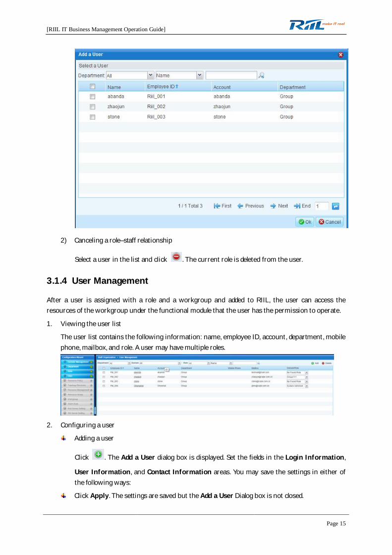
Click . The Add a User dialog box is displayed. Select the role to be assigned and the
users that are not assigned with the role. Role information will be automatically added to theUser Information tab page. The Staff Organization–User Management module and StaffOrganization–Role Management module are updated accordingly.

[RIIL IT Business Management Operation Guide]
Page 11
2) Canceling the domain–role relationship. Select the role of a user to be deleted and click
. The role is deleted from the user.
3. Configuring domain resources
Select a domain and click the Resource List tab to add resources to the domain.
You can add resources to a domain manually or by configuring allocation rules.
1) Click . The Resource Allocation Rule dialog box is displayed. Define
resource allocation rules in the Rule List area based on the Note below and click Save. Afterthat, all resources that comply with the defined rules are automatically allocated to thecurrent domain.

[RIIL IT Business Management Operation Guide]
Page 12
2) To add unallocated resources manually, click .
Note: When domain management configuration is completed, users in the domain can log in toRIIL and view functional modules and resources in the domain that they have permissions to onthe foreground.
3.1.2 Department Management
1. Creating a department
1) Click . On the General Information tag page, set the Dept.No., Dept.Name, Superior
Dept., and Description fields and click Apply. A department is created.

[RIIL IT Business Management Operation Guide]
Page 13
2) To modify department information, select a department and edit the information of thedepartment.
2. Adding department staff
Select an existing department and add/delete staff to/from the department on the UseInformation tab page.
3. Deleting a department
Select a department and click .
3.1.3 Role Management
Roles are used to organize the permissions to operate tabs. A user can have the permission to operatemultiple tabs. After a user is assigned with a role, the user has access to the corresponding functionaltabs.
Five roles are predefined in RIIL: configuration administrator, monitoring administrator, equipmentroom administrator, IT department administrator, and knowledge base administrator. The predefinedroles can meet general requirements.
1. Defining a role
1) Creating a role: Click . On the General Information tab page, set the Role Type, Name,
and Description fields and click Apply. A role is created.

[RIIL IT Business Management Operation Guide]
Page 14
2) Configuring the functions that a role has the permission to use: Select a new role, click theFunction Authorization tab, select the required functions listed below, and click Apply.
2. Assigning a role to a user
Select a role and click the User Information tab to add/delete staff to/from the role.
The following list displays all the records of users in the selected role.
1) Creating a role–staff relationship
Click . The Add a User dialog box is displayed. When you complete domain and user
configurations, click OK.
[RIIL IT Business Management Operation Guide]
Page 15
2) Canceling a role–staff relationship
Select a user in the list and click . The current role is deleted from the user.
3.1.4 User Management
After a user is assigned with a role and a workgroup and added to RIIL, the user can access theresources of the workgroup under the functional module that the user has the permission to operate.
1. Viewing the user list
The user list contains the following information: name, employee ID, account, department, mobilephone, mailbox, and role. A user may have multiple roles.
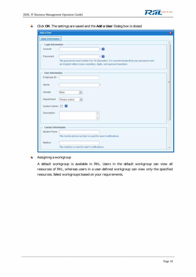
2. Configuring a user
Adding a user
Click . The Add a User dialog box is displayed. Set the fields in the Login Information,
User Information, and Contact Information areas. You may save the settings in either ofthe following ways:
Click Apply. The settings are saved but the Add a User Dialog box is not closed.
[RIIL IT Business Management Operation Guide]
Page 16
Click OK. The settings are saved and the Add a User Dialog box is closed.
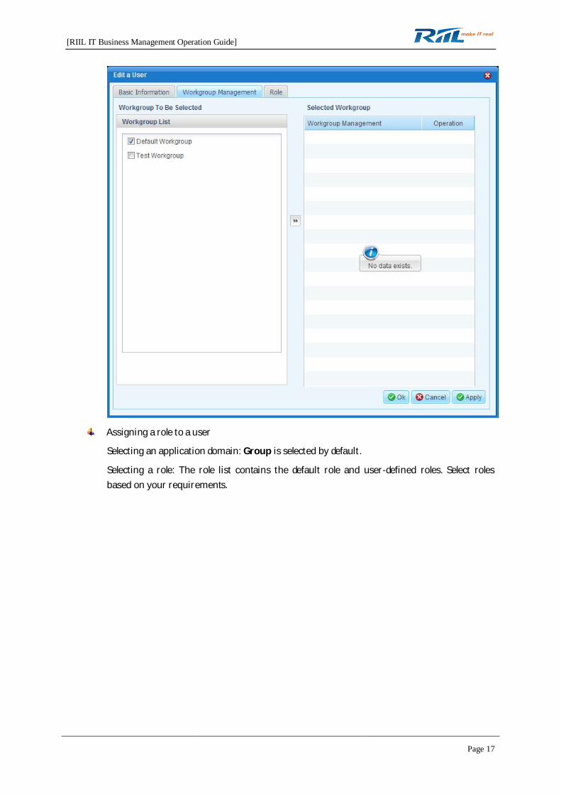
Assigning a workgroup
A default workgroup is available in RIIL. Users in the default workgroup can view allresources of RIIL, whereas users in a user-defined workgroup can view only the specifiedresources. Select workgroups based on your requirements.
[RIIL IT Business Management Operation Guide]
Page 17
Assigning a role to a user
Selecting an application domain: Group is selected by default.
Selecting a role: The role list contains the default role and user-defined roles. Select rolesbased on your requirements.

[RIIL IT Business Management Operation Guide]
Page 18
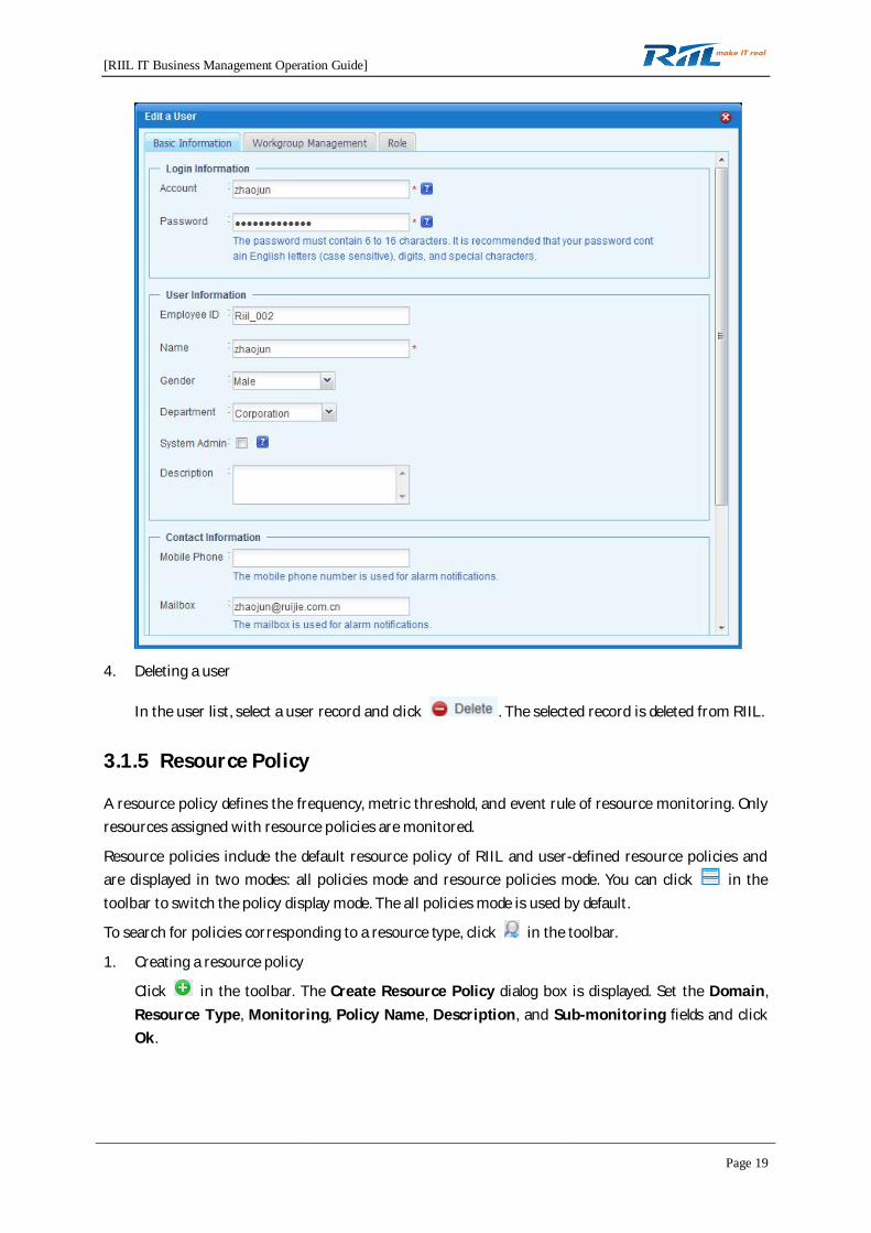
3. Modifying user information
In the user list, click the name in a user record. The Edit a User dialog box is displayed. You canmodify information on the Basic Information, Workgroup Management, and Role tab pages.
[RIIL IT Business Management Operation Guide]
Page 19
4. Deleting a user
In the user list, select a user record and click . The selected record is deleted from RIIL.
3.1.5 Resource Policy
A resource policy defines the frequency, metric threshold, and event rule of resource monitoring. Onlyresources assigned with resource policies are monitored.
Resource policies include the default resource policy of RIIL and user-defined resource policies andare displayed in two modes: all policies mode and resource policies mode. You can click in thetoolbar to switch the policy display mode. The all policies mode is used by default.
To search for policies corresponding to a resource type, click in the toolbar.
1. Creating a resource policy
Click in the toolbar. The Create Resource Policy dialog box is displayed. Set the Domain,Resource Type, Monitoring, Policy Name, Description, and Sub-monitoring fields and clickOk.

[RIIL IT Business Management Operation Guide]
Page 20
2. Enabling a resource policy
You may enable resource policies one by one or in batches.
Enabling a single resource policy at a time
Enabling multiple resource policies in batches
[RIIL IT Business Management Operation Guide]
Page 21
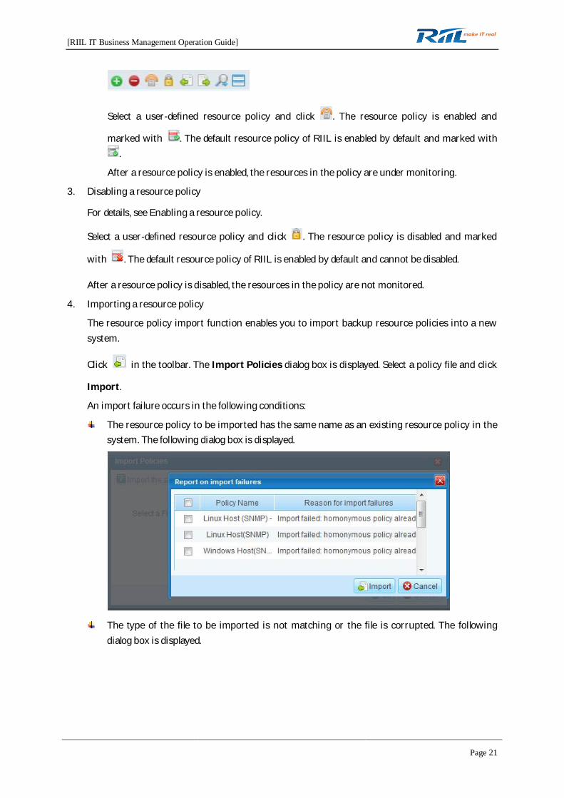
Select a user-defined resource policy and click . The resource policy is enabled and
marked with . The default resource policy of RIIL is enabled by default and marked with.
After a resource policy is enabled, the resources in the policy are under monitoring.
3. Disabling a resource policy
For details, see Enabling a resource policy.
Select a user-defined resource policy and click . The resource policy is disabled and marked
with . The default resource policy of RIIL is enabled by default and cannot be disabled.
After a resource policy is disabled, the resources in the policy are not monitored.
4. Importing a resource policy
The resource policy import function enables you to import backup resource policies into a newsystem.
Click in the toolbar. The Import Policies dialog box is displayed. Select a policy file and click
Import.
An import failure occurs in the following conditions:
The resource policy to be imported has the same name as an existing resource policy in thesystem. The following dialog box is displayed.
The type of the file to be imported is not matching or the file is corrupted. The followingdialog box is displayed.

[RIIL IT Business Management Operation Guide]
Page 22
5. Exporting a resource policy
The resource policy export function enables you to export resource policies for backup andimport the backup resource policies into a new system later.
For details, see Disabling a resource policy.
Click . The File Download dialog box is displayed. Click Save.
6. Configuring a resource policy
1) Resource Relation
Select a resource policy and click the Resource Relation tab. The Resource Relation tabpage is displayed.
i. Adding resources to a resource policy for monitoring
Adding resources by resource list
Click . The Resource List dialog box is displayed. Add resources that needto be monitored by the current resource policy and click Ok.

[RIIL IT Business Management Operation Guide]
Page 23
Adding resources by resource group
Click . The Add by resource group dialog box is
displayed. Select a resource group and click Ok. The resources in the resource
group that match the resource policy type are added to the Resources Contained
in the Policy list.
ii. Removing resources from a resource policy
Select the resources to be removed from a resource policy and click .
To remove all resources from a resource policy, click .
2) Metric Configuration
A resource policy includes the availability metric, performance metric, configuration metric,and information metric, which are used to test the attributes of resources. After youconfigure the metrics to be monitored, these metrics are displayed on the foreground.
To restore factory defaults, click .
[RIIL IT Business Management Operation Guide]
Page 24
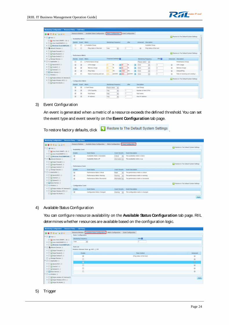
3) Event Configuration
An event is generated when a metric of a resource exceeds the defined threshold. You can setthe event type and event severity on the Event Configuration tab page.
To restore factory defaults, click .
4) Available Status Configuration
You can configure resource availability on the Available Status Configuration tab page. RIILdetermines whether resources are available based on the configuration logic.
5) Trigger
[RIIL IT Business Management Operation Guide]
Page 25
You can configure a trigger on the Trigger Configuration tab page, which is available onlyfor resource policies discovered through WMI, SSH, and Telnet.
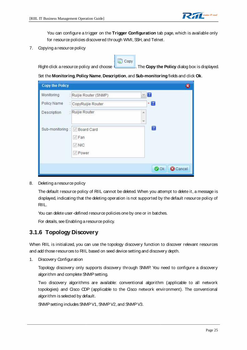
7. Copying a resource policy
Right-click a resource policy and choose . The Copy the Policy dialog box is displayed.
Set the Monitoring, Policy Name, Description, and Sub-monitoring fields and click Ok.
8. Deleting a resource policy
The default resource policy of RIIL cannot be deleted. When you attempt to delete it, a message isdisplayed, indicating that the deleting operation is not supported by the default resource policy ofRIIL.
You can delete user-defined resource policies one by one or in batches.
For details, see Enabling a resource policy.
3.1.6 Topology Discovery
When RIIL is initialized, you can use the topology discovery function to discover relevant resourcesand add those resources to RIIL based on seed device setting and discovery depth.
1. Discovery Configuration
Topology discovery only supports discovery through SNMP. You need to configure a discoveryalgorithm and complete SNMP setting.
Two discovery algorithms are available: conventional algorithm (applicable to all networktopologies) and Cisco CDP (applicable to the Cisco network environment). The conventionalalgorithm is selected by default.
SNMP setting includes SNMP V1, SNMP V2, and SNMP V3.

[RIIL IT Business Management Operation Guide]
Page 26
Click and set discovery criteria.
For SNMP V1/V2, set the read-only community and read-write community. For SNMP V3, setthe IP address, port number, security level, authentication protocol, proprietary protocol, andcontext.
To delete a set discovery criterion, select the criterion and click .
2. Topology Discovery
When the discovery configuration is completed, go to the Topology Discovery tab page, in whichyou can set the following items: Seed Device Setting, Add a subnet/Shield a subnet,Discovery Depth, and Discovery Method.
[RIIL IT Business Management Operation Guide]
Page 27
You can set the IP address of the seed device to the IP address of a core device on the network.
The discovery depth specifies the number of routes from the IP address of the seed device.
Select a discovery method based on the following principles:
Click Re-discovery when topology discovery is performed for the first time.
Click Supplementary discovery when supplementary discovery is performed based on theoriginal discovery result.
Click to save the settings on the Topology Discovery tab page.
Click to discover network topologies and resources.
Topology discovery is implemented in three steps.
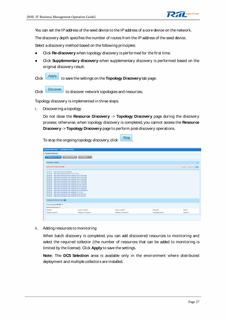
i. Discovering a topology
Do not close the Resource Discovery -> Topology Discovery page during the discoveryprocess; otherwise, when topology discovery is completed, you cannot access the ResourceDiscovery -> Topology Discovery page to perform post-discovery operations.
To stop the ongoing topology discovery, click .
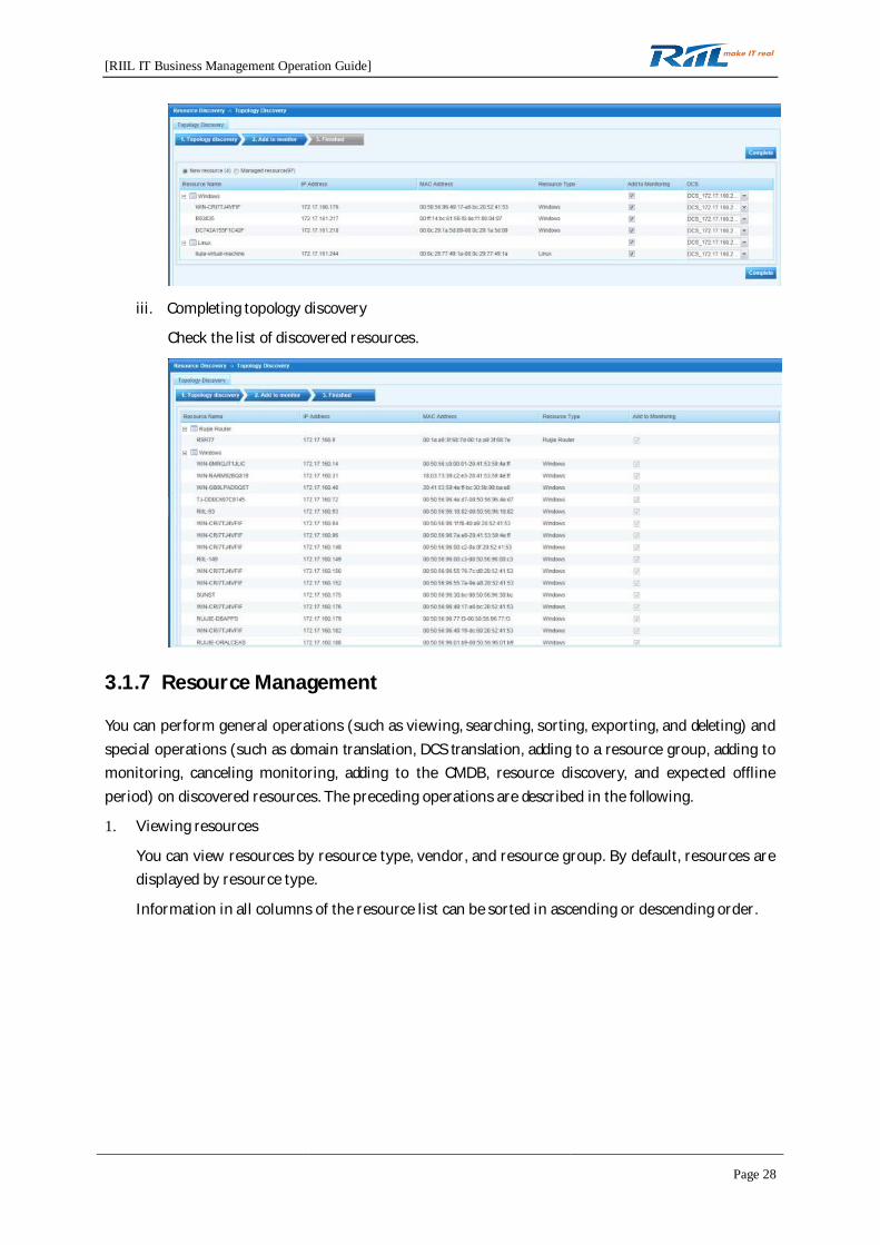
ii. Adding resources to monitoring
When batch discovery is completed, you can add discovered resources to monitoring andselect the required collector (the number of resources that can be added to monitoring islimited by the license). Click Apply to save the settings.
Note: The DCS Selection area is available only in the environment where distributeddeployment and multiple collectors are installed.
[RIIL IT Business Management Operation Guide]
Page 28
iii. Completing topology discovery
Check the list of discovered resources.
3.1.7 Resource Management
You can perform general operations (such as viewing, searching, sorting, exporting, and deleting) andspecial operations (such as domain translation, DCS translation, adding to a resource group, adding tomonitoring, canceling monitoring, adding to the CMDB, resource discovery, and expected offlineperiod) on discovered resources. The preceding operations are described in the following.
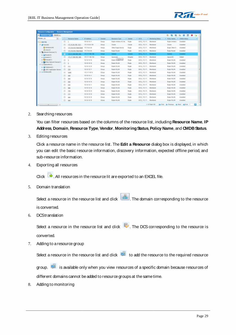
1. Viewing resources
You can view resources by resource type, vendor, and resource group. By default, resources aredisplayed by resource type.
Information in all columns of the resource list can be sorted in ascending or descending order.
[RIIL IT Business Management Operation Guide]
Page 29
2. Searching resources
You can filter resources based on the columns of the resource list, including Resource Name, IPAddress, Domain, Resource Type, Vendor, Monitoring Status, Policy Name, and CMDB Status.
3. Editing resources
Click a resource name in the resource list. The Edit a Resource dialog box is displayed, in whichyou can edit the basic resource information, discovery information, expected offline period, andsub-resource information.
4. Exporting all resources
Click . All resources in the resource lit are exported to an EXCEL file.
5. Domain translation
Select a resource in the resource list and click . The domain corresponding to the resource
is converted.
6. DCS translation
Select a resource in the resource list and click . The DCS corresponding to the resource is
converted.
7. Adding to a resource group
Select a resource in the resource list and click to add the resource to the required resource
group. is available only when you view resources of a specific domain because resources of
different domains cannot be added to resource groups at the same time.
8. Adding to monitoring
[RIIL IT Business Management Operation Guide]
Page 30
Select a resource in the resource list and click to add the resource to monitoring. The
monitored resource is displayed on the foreground.
9. Canceling monitoring
Select a resource in the resource list and click to cancel monitoring of the resource. The
unmonitored resource is cleared from the foreground.
10. Adding to the CMDB
Select a resource in the resource list and click to add the resource to the CMDB, through
which you can manage the configuration and change of the resource. The resource is markedwith Added in the CMDB column.
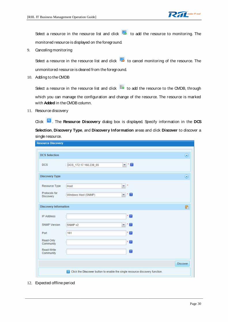
11. Resource discovery
Click . The Resource Discovery dialog box is displayed. Specify information in the DCS
Selection, Discovery Type, and Discovery Information areas and click Discover to discover asingle resource.
12. Expected offline period

[RIIL IT Business Management Operation Guide]
Page 31
Select a resource in the resource list and click . The Expected Offline Period dialog box is
displayed, in which you can add an expected offline period.
13. Deleting resources
Select a resource in the resource list and click . The resource is deleted from RIIL.
3.1.8 Resource Group Management
You can divide resources into different resource groups based on the actual application requirementsto facilitate application and management.
1. Creating a resource group
Click . On the General Information tab page, set the Name and Description fields and click
.
2. Adding resources
Select a resource group. On the Resource List tab page, you can add/delete resources to/from theresource group.
3. Deleting a resource group
Select a resource group and click .
[RIIL IT Business Management Operation Guide]
Page 32
3.1.9 Workgroup Management
Workgroups are used to organize the permissions to operate resources. Users in a workgroup haveaccess to the resources of the workgroup.
Workgroups include the default workgroup and user-defined workgroups.
1. Creating a workgroup
Click . On the General Information tab page, set the Name and Description fields and click
.
2. Adding a user to a workgroup
Select a workgroup. On the User Information tab page, you can add/delete a user to/from theworkgroup.
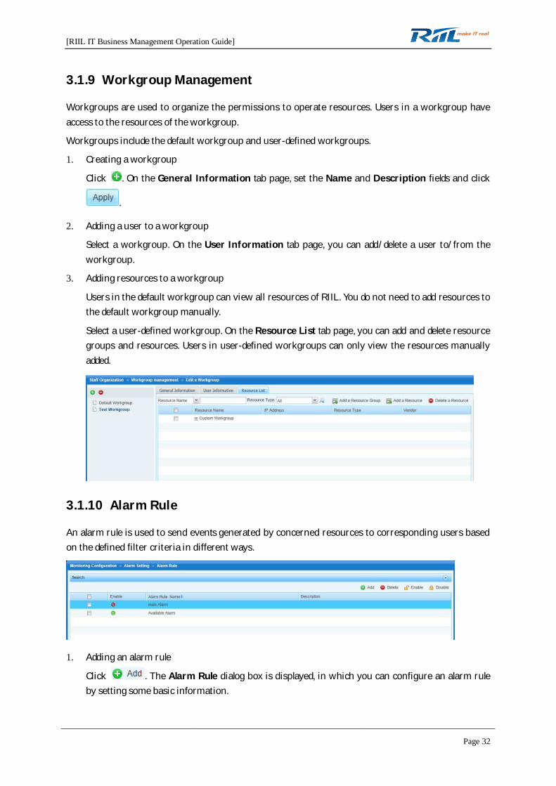
3. Adding resources to a workgroup
Users in the default workgroup can view all resources of RIIL. You do not need to add resources tothe default workgroup manually.
Select a user-defined workgroup. On the Resource List tab page, you can add and delete resourcegroups and resources. Users in user-defined workgroups can only view the resources manuallyadded.
3.1.10 Alarm Rule
An alarm rule is used to send events generated by concerned resources to corresponding users basedon the defined filter criteria in different ways.
1. Adding an alarm rule
Click . The Alarm Rule dialog box is displayed, in which you can configure an alarm ruleby setting some basic information.
[RIIL IT Business Management Operation Guide]
Page 33
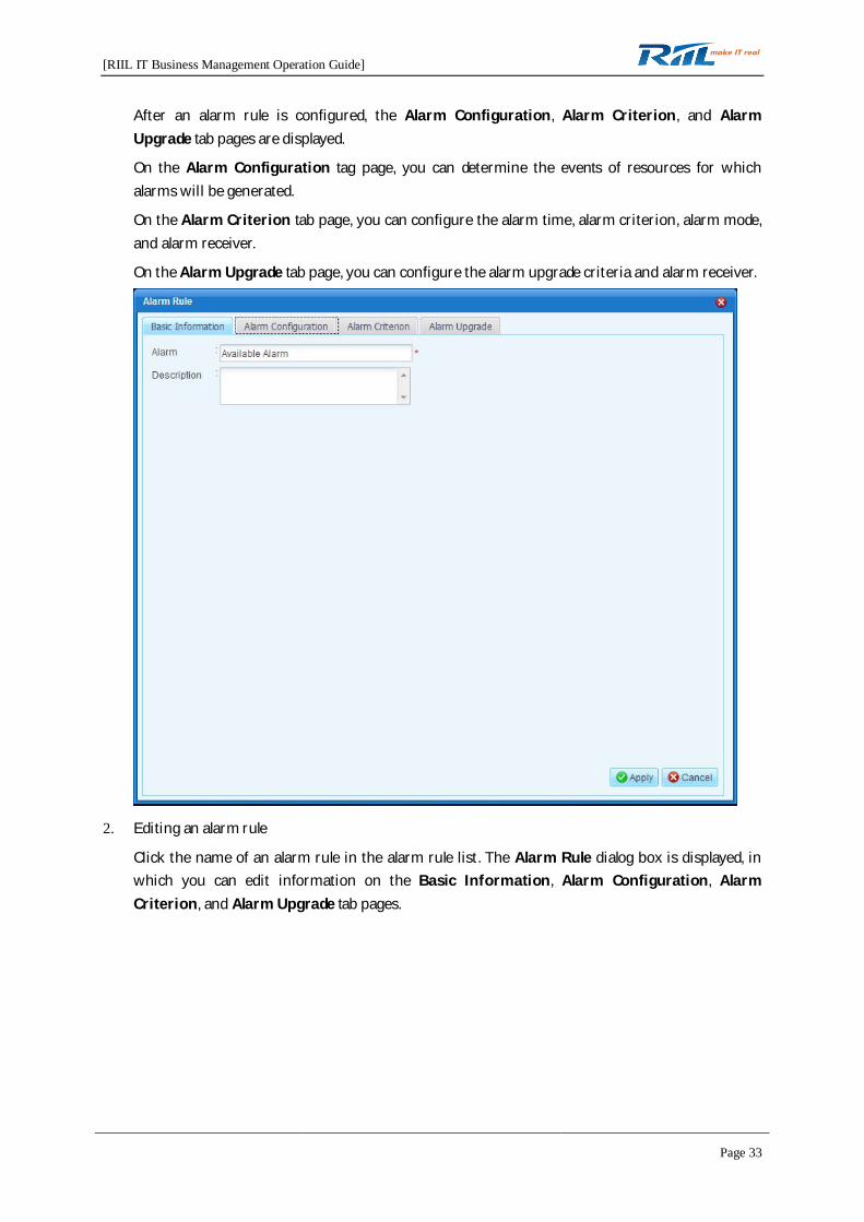
After an alarm rule is configured, the Alarm Configuration, Alarm Criterion, and AlarmUpgrade tab pages are displayed.
On the Alarm Configuration tag page, you can determine the events of resources for whichalarms will be generated.
On the Alarm Criterion tab page, you can configure the alarm time, alarm criterion, alarm mode,and alarm receiver.
On the Alarm Upgrade tab page, you can configure the alarm upgrade criteria and alarm receiver.
2. Editing an alarm rule
Click the name of an alarm rule in the alarm rule list. The Alarm Rule dialog box is displayed, inwhich you can edit information on the Basic Information, Alarm Configuration, AlarmCriterion, and Alarm Upgrade tab pages.
[RIIL IT Business Management Operation Guide]
Page 34
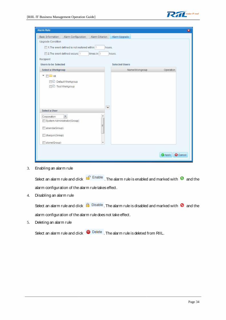
3. Enabling an alarm rule
Select an alarm rule and click . The alarm rule is enabled and marked with and the
alarm configuration of the alarm rule takes effect.
4. Disabling an alarm rule
Select an alarm rule and click . The alarm rule is disabled and marked with and the
alarm configuration of the alarm rule does not take effect.
5. Deleting an alarm rule
Select an alarm rule and click . The alarm rule is deleted from RIIL.

[RIIL IT Business Management Operation Guide]
Page 35
3.1.11 Mail Server Setting
1. Basic Information
In the Basic Information area, you can specify the following information for a mail server: ServerAddress, Server Port, Whether to Authenticate, Outgoing Mailbox, and Text Mailbox.
To send a test email to the test mailbox, click .
To update the settings of the mail server, click .
2. Email Template List
The Email Template List area provides you with a default mail alarm template. You can alsodefine a different mail alarm template.
To create a mail template, click .

[RIIL IT Business Management Operation Guide]
Page 36
To delete a mail template, click .
To import a mail template, click .
To export a mail template, click .
You can click a mail alarm template and view or modify it. The default mail alarm template canonly be viewed and cannot be modified.
3.1.12 Short Message Server Setting
1. Short Message Gateway Configuration
In the Short Message Gateway Configuration area, you can specify the following informationfor a short message server: COM Port Number, Baud Rate, PIN of a SIM Card, Vendor, andModel.
To send a test email to the test mailbox, click .
To update the settings of the short message server, click .

[RIIL IT Business Management Operation Guide]
Page 37
2. Short Message Template List
The Short Message Template List area provides you with a default short message alarmtemplate. You can also define a different short message alarm template.
To create a short message template, click .
To delete a short message template, click .
To import a short message template, click .
To export a short message template, click .
You can click a short message alarm template and view or modify it.
4 Functional Details
4.1 System Management
System management is the basic configuration module of RIIL, which provides data support forforeground resources and topologies. The following modules need to be configured: Staff Organization,Domain Management, Resource Discovery & Configuration, Monitoring Configuration, and SystemConfiguration. The following sections describe how to configure these modules.
4.1.1 Staff Organization
4.1.1.1 Staff Organization
Staff organization is carried out in the department, user, role, and workgroup dimensions.
1. Department management
You can create a department, add staff to a department, and delete a department throughdepartment management.
[RIIL IT Business Management Operation Guide]
Page 38
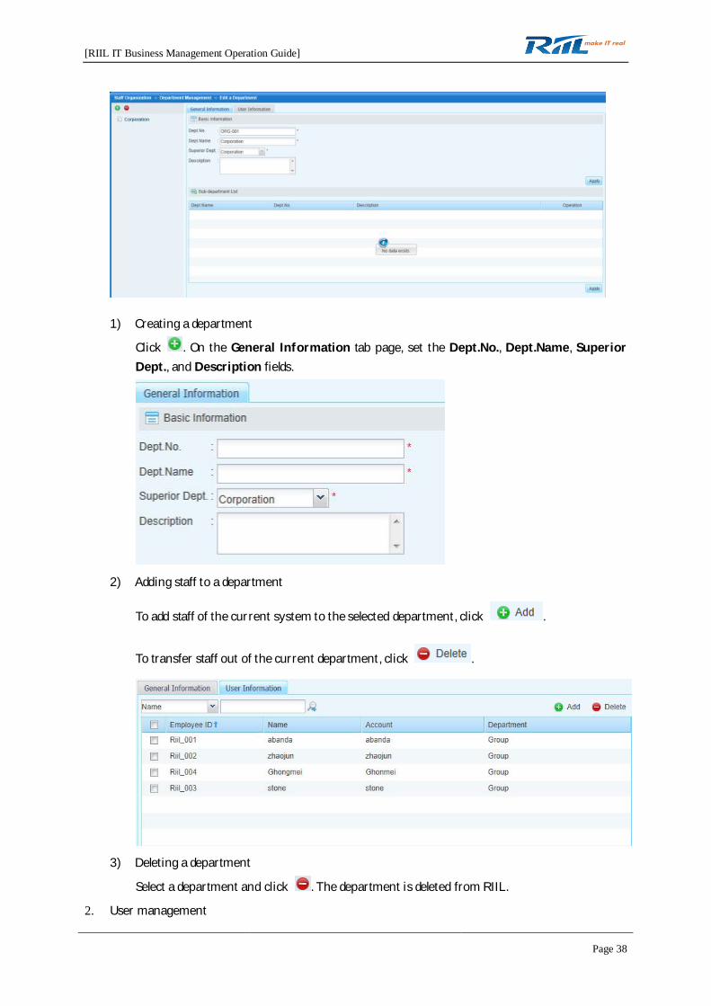
1) Creating a department
Click . On the General Information tab page, set the Dept.No., Dept.Name, SuperiorDept., and Description fields.
2) Adding staff to a department
To add staff of the current system to the selected department, click .
To transfer staff out of the current department, click .
3) Deleting a department
Select a department and click . The department is deleted from RIIL.
2. User management

[RIIL IT Business Management Operation Guide]
Page 39
RIIL provides an entry for management of user account information. You can search and createusers and assign workgroups and roles to users.
1) Searching for a user
You can search for a user by department, name, account, and employee ID. Users that meetthe search criteria are displayed in the user list. By default, all users are displayed.
2) Creating a user
Click . The Add a User dialog box is displayed. Specify information in the Login
Information, User Information, and Contact Information areas and click Apply.
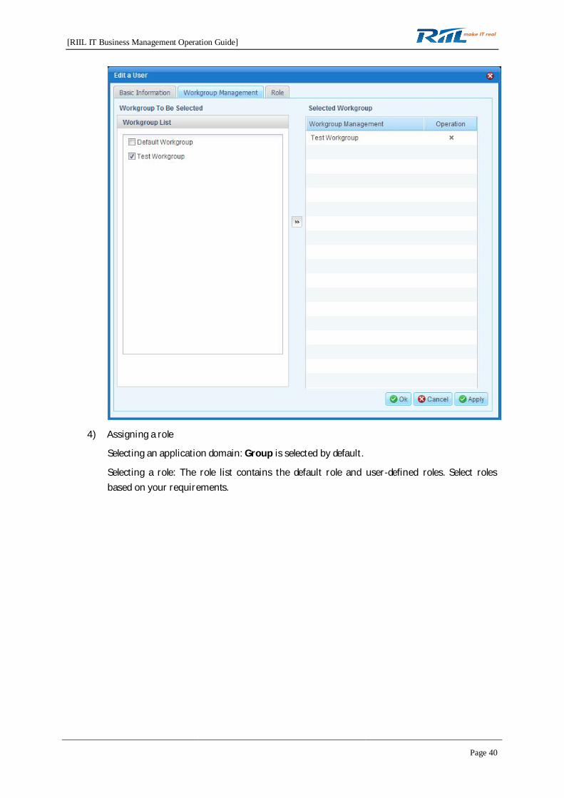
3) Assigning a workgroup
A default workgroup is available in RIIL. Users in the default workgroup can view allresources of RIIL, whereas users in a user-defined workgroup can view only the specifiedresources. Select workgroups based on your requirements.
[RIIL IT Business Management Operation Guide]
Page 40
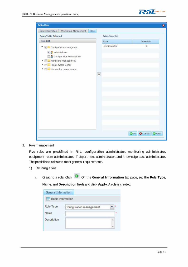
4) Assigning a role
Selecting an application domain: Group is selected by default.
Selecting a role: The role list contains the default role and user-defined roles. Select rolesbased on your requirements.
[RIIL IT Business Management Operation Guide]
Page 41
3. Role management
Five roles are predefined in RIIL: configuration administrator, monitoring administrator,equipment room administrator, IT department administrator, and knowledge base administrator.The predefined roles can meet general requirements.
1) Defining a role
i. Creating a role: Click . On the General Information tab page, set the Role Type,
Name, and Description fields and click Apply. A role is created.

[RIIL IT Business Management Operation Guide]
Page 42
ii. Configuring the functions that a role has the permission to operate: Select a new role,click the Function Authorization tab, select the required functions listed below, andclick Apply.
2) Assigning a role to a user
Select a role and click the User Information tab to add/delete staff to/from the role.
The following list displays all user records of the selected role.
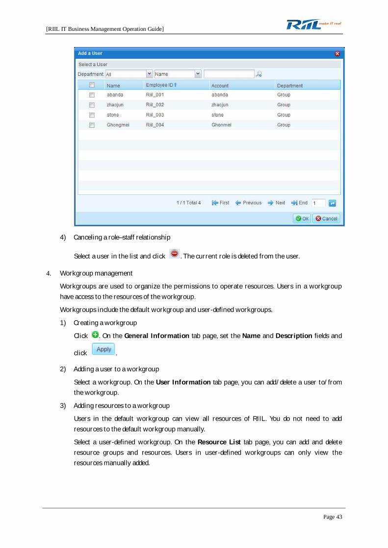
3) Creating a role–staff relationship
Click . The Add a User dialog box is displayed. When you complete user configuration,
click OK.
[RIIL IT Business Management Operation Guide]
Page 43
4) Canceling a role–staff relationship
Select a user in the list and click . The current role is deleted from the user.
4. Workgroup management
Workgroups are used to organize the permissions to operate resources. Users in a workgrouphave access to the resources of the workgroup.
Workgroups include the default workgroup and user-defined workgroups.
1) Creating a workgroup
Click . On the General Information tab page, set the Name and Description fields and
click .
2) Adding a user to a workgroup
Select a workgroup. On the User Information tab page, you can add/delete a user to/fromthe workgroup.
3) Adding resources to a workgroup
Users in the default workgroup can view all resources of RIIL. You do not need to addresources to the default workgroup manually.
Select a user-defined workgroup. On the Resource List tab page, you can add and deleteresource groups and resources. Users in user-defined workgroups can only view theresources manually added.
[RIIL IT Business Management Operation Guide]
Page 44
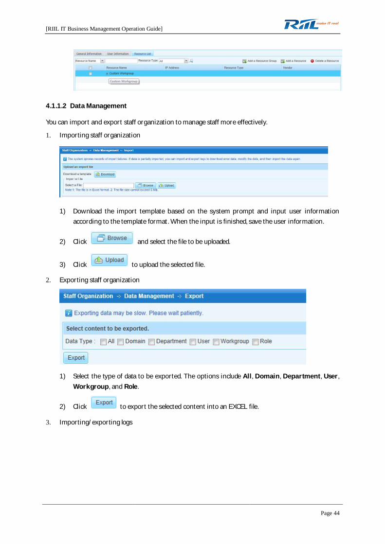
4.1.1.2 Data Management
You can import and export staff organization to manage staff more effectively.
1. Importing staff organization
1) Download the import template based on the system prompt and input user informationaccording to the template format. When the input is finished, save the user information.
2) Click and select the file to be uploaded.
3) Click to upload the selected file.
2. Exporting staff organization
1) Select the type of data to be exported. The options include All, Domain, Department, User,Workgroup, and Role.
2) Click to export the selected content into an EXCEL file.
3. Importing/exporting logs

[RIIL IT Business Management Operation Guide]
Page 45
1) Checking exported/imported logs
On the Imported/Exported Logs page, you can view the operating time, operator,operation type, name of the imported file, and operation result. You can also downloadimported files. If an import failure record exists, you can download the corresponding file andmodify it for re-import.
2) Deleting exported/imported logs
To delete an existing log, select the corresponding log record and click .
3) Clearing all imported/exported log records
To clear all imported/exported log records from the log list, click .
4.1.2 Domain Management
For details, see section 3.1.1 "Domain Management."
4.1.3 Resource Discovery & Configuration
This section describes how to discover resources and configure discovered resources.
4.1.3.1 Resource Discovery
1. Single resource discovery

[RIIL IT Business Management Operation Guide]
Page 46
Resources that can be discovered include hosts, network devices, storage devices,applications, and basic services.
You can discover a single resource manually through SNMP, WMI, or SSH/Telnet.
To enable the single resource discovery function, specify information in the DCS Selection,Discovery Type, and Discovery Information areas and click Discover.
When resource discovery fails, check whether the prerequisites for resource discovery are
met. Click to view the help information.
Note: The DCS Selection area is available only in the environment where distributed deploymentand multiple collectors are installed.
You can set resource information when resource discovery is successful. Different types ofresources are added to the monitoring of corresponding types of default policies. The number ofresources that can be added to monitoring is limited by the license. If the number of resources in
[RIIL IT Business Management Operation Guide]
Page 47
resource management exceeds the upper limit specified in the license, not all resources can beadded to monitoring.
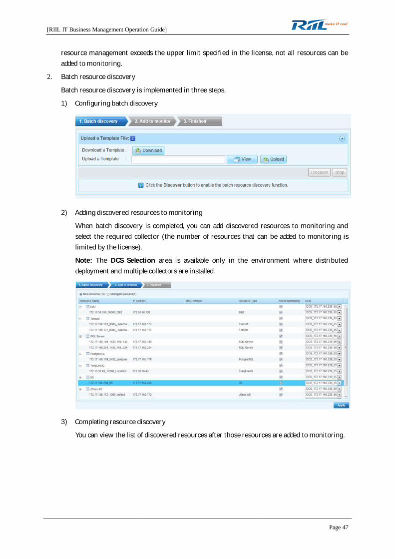
2. Batch resource discovery
Batch resource discovery is implemented in three steps.
1) Configuring batch discovery
2) Adding discovered resources to monitoring
When batch discovery is completed, you can add discovered resources to monitoring andselect the required collector (the number of resources that can be added to monitoring islimited by the license).
Note: The DCS Selection area is available only in the environment where distributeddeployment and multiple collectors are installed.
3) Completing resource discovery
You can view the list of discovered resources after those resources are added to monitoring.

[RIIL IT Business Management Operation Guide]
Page 48
3. Topology discovery
For details, see section 3.1.6 "Topology Discovery."
4.1.3.2 Resource Configuration
1. Resource management
For details, see section 3.1.7 "Resource Management ."
2. Resource group management
For details, see section 3.1.8 "Resource Group Management."
4.1.4 Monitoring Configuration
4.1.4.1 Resource Policy
For details, see section 3.1.5 "Resource Policy."
4.1.4.2 Log Policy
A log policy defines monitoring rules for logs generated by devices under monitoring. Those logsinclude Windows logs and syslogs.

[RIIL IT Business Management Operation Guide]
Page 49
Windows log policy: defines monitoring rules for syslogs generated by Windows devices undermonitoring.
Syslog policy: defines monitoring rules for syslogs generated by Unix devices and network devicesunder monitoring.
Log policy-related operations are described in the following.
1. Creating a log policy
Click on the Resource Relation tab page. The Create Log Policy dialog box is displayed. Setthe Policy Type and Policy Name fields. Click Ok.
1) Resource Relation
To establish a relation between log policies and resources, click .To cancel the relation between log policies and all resources, click .
To cancel the relation between log policies and selected resources, click .
2) Event Configuration
You can set log events on the Event Configuration tab page. Log events take effect only afterbeing enabled.
i. Adding an event
Select a log event, click Add, and set basic information and log rules.
ii. Enabling an event

[RIIL IT Business Management Operation Guide]
Page 50
Select a log event and click Enable. After being enabled, the event is marked with .
iii. Disabling an event
Select a log event and click Disable. After being disabled, the event is marked withand does not take effect. Log events that match the settings of the selected event will notbe generated.
iv. Deleting an event
Select a log event and click Delete.
2. Enabling a log policy
Select a log policy and click . For details, see Enabling a resource policy.
3. Disabling a log policy
Select a log policy and click . The disabling mode is the same as the enabling mode.
4. Importing a log policy
Click . The Import Policies dialog box is displayed. Click and select the
file to be imported. Then, click Ok.
Note: If the policy to be imported has the same name as an existing policy of RIIL, the policycannot be imported.

[RIIL IT Business Management Operation Guide]
Page 51
5. Exporting a log policy
Select a log policy and click . The policy will be exported for backup. The export mode is the
same as the log enabling mode.
4.1.4.3 Script Policy
A script policy defines monitoring rules for script files generated by a device. Scripts are classified intotiming scripts and advanced scripts.
Timing script policy: defines monitoring rules based on the values returned after script files areexecuted. You can set when to execute this policy.
Advanced script policy: defines script monitoring rules for support of secondary development.
1. Creating a script policy
Click . The Create Script Policy dialog box is displayed. Set the Policy Type and Policy
Name fields.
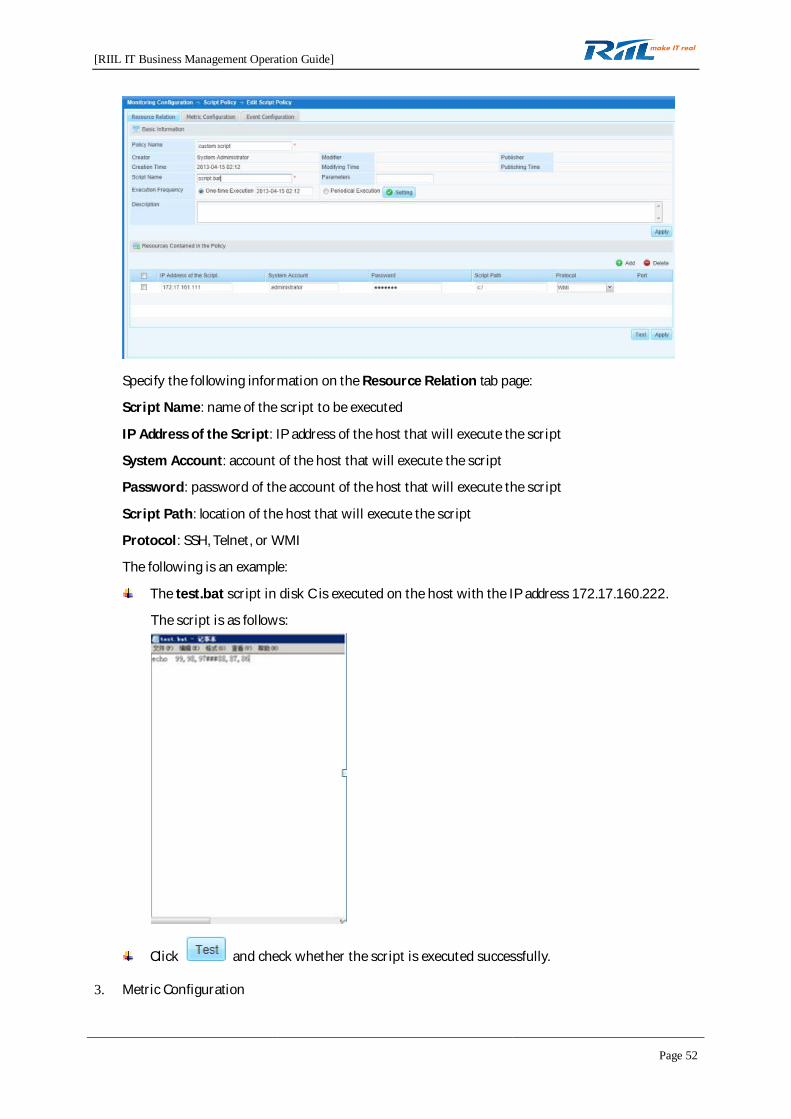
2. Resource Relation
You can set resources related with a script policy on the Resource Relation tab page.
[RIIL IT Business Management Operation Guide]
Page 52
Specify the following information on the Resource Relation tab page:
Script Name: name of the script to be executed
IP Address of the Script: IP address of the host that will execute the script
System Account: account of the host that will execute the script
Password: password of the account of the host that will execute the script
Script Path: location of the host that will execute the script
Protocol: SSH, Telnet, or WMI
The following is an example:
The test.bat script in disk C is executed on the host with the IP address 172.17.160.222.
The script is as follows:
Click and check whether the script is executed successfully.
3. Metric Configuration

[RIIL IT Business Management Operation Guide]
Page 53
You can set metrics for a script on the Metric Configuration tab page.
4. Event Configuration
You can set events for a script on the Event Configuration tab page.
4.1.4.4 SNMP Trap Policy
An SNMP Trap policy defines monitoring rules for SNMP Trap of a device under monitoring.
1. Creating an SNMP Trap policy
Click . The Create SNMP Trap Policy dialog box is displayed. Set the Policy Name and
Description fields.
2. Resource Relation
You can set resources related with an SNMP Trap policy on the Resource Relation tab page.
[RIIL IT Business Management Operation Guide]
Page 54
3. Metric Configuration
4. Event Configuration
4.1.4.5 Alarm Configuration
For details, see section 3.1.10 "Alarm Rule ."
4.1.4.6 Monitor System Information
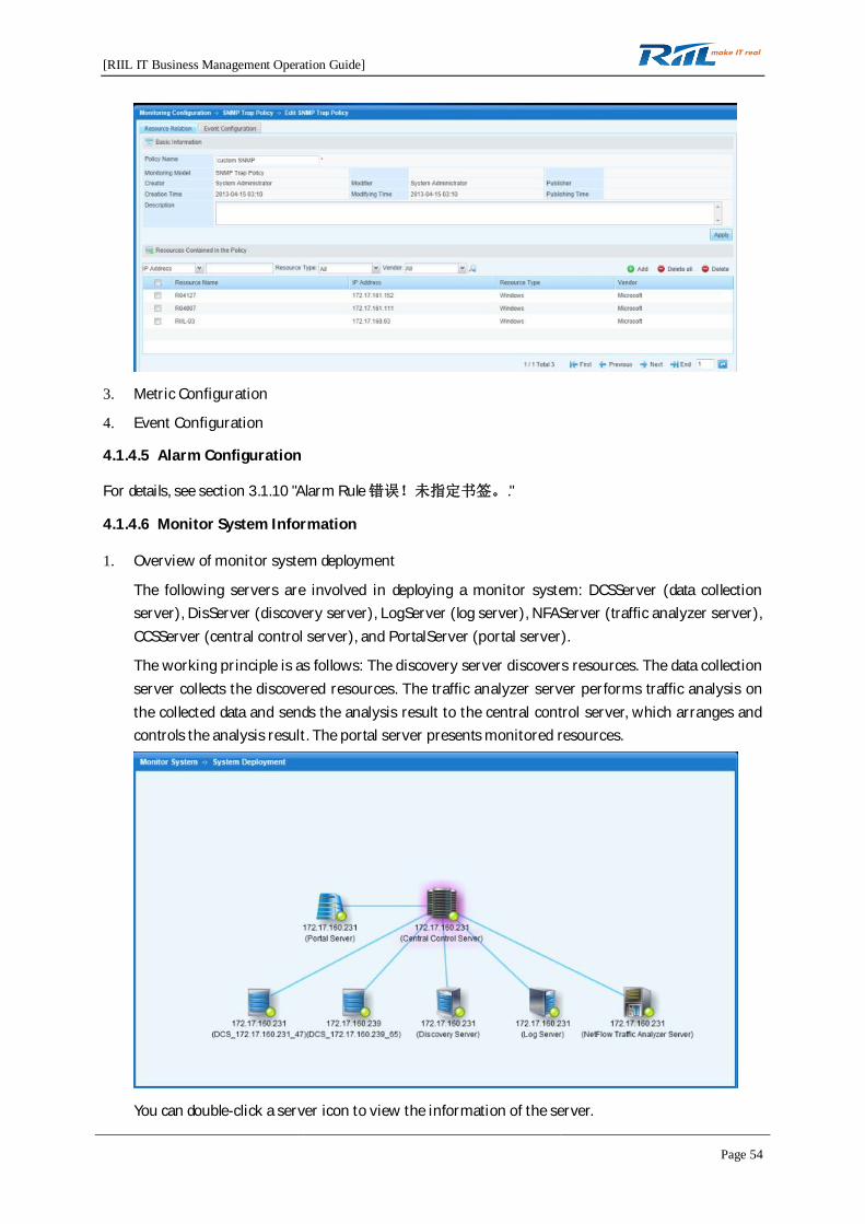
1. Overview of monitor system deployment
The following servers are involved in deploying a monitor system: DCSServer (data collectionserver), DisServer (discovery server), LogServer (log server), NFAServer (traffic analyzer server),CCSServer (central control server), and PortalServer (portal server).
The working principle is as follows: The discovery server discovers resources. The data collectionserver collects the discovered resources. The traffic analyzer server performs traffic analysis onthe collected data and sends the analysis result to the central control server, which arranges andcontrols the analysis result. The portal server presents monitored resources.
You can double-click a server icon to view the information of the server.

[RIIL IT Business Management Operation Guide]
Page 55
1) DCSServer (data collection server): You can view information of this server on the BasicInformation, Monitored Resource, and Monitored Metric tab pages of the DCS Serverwindow.
2) DisServer (discovery server): You can view information of this server on the BasicInformation tab page of the Dis Server window.
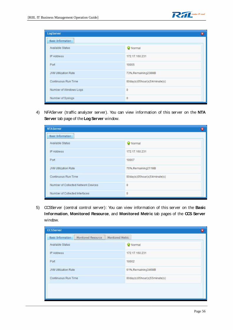
3) LogServer (log server): You can view information of this server on the Basic Informationtab page of the Log Server window.
[RIIL IT Business Management Operation Guide]
Page 56
4) NFAServer (traffic analyzer server). You can view information of this server on the NTAServer tab page of the Log Server window.
5) CCSServer (central control server): You can view information of this server on the BasicInformation, Monitored Resource, and Monitored Metric tab pages of the CCS Serverwindow.
[RIIL IT Business Management Operation Guide]
Page 57
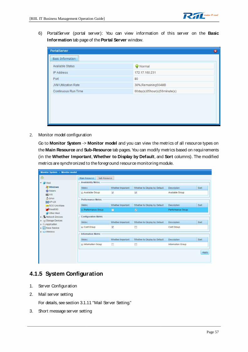
6) PortalServer (portal server): You can view information of this server on the BasicInformation tab page of the Portal Server window.
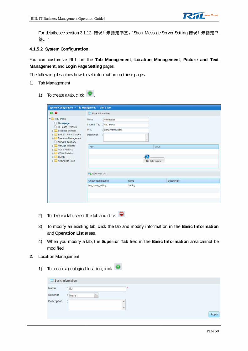
2. Monitor model configuration
Go to Monitor System -> Monitor model and you can view the metrics of all resource types onthe Main Resource and Sub-Resource tab pages. You can modify metrics based on requirements(in the Whether Important, Whether to Display by Default, and Sort columns). The modifiedmetrics are synchronized to the foreground resource monitoring module.
4.1.5 System Configuration
1. Server Configuration
2. Mail server setting
For details, see section 3.1.11 "Mail Server Setting."
3. Short message server setting
[RIIL IT Business Management Operation Guide]
Page 58
For details, see section 3.1.12 "Short Message Server Setting."
4.1.5.2 System Configuration
You can customize RIIL on the Tab Management, Location Management, Picture and TextManagement, and Login Page Setting pages.
The following describes how to set information on these pages.
1. Tab Management
1) To create a tab, click .
2) To delete a tab, select the tab and click .
3) To modify an existing tab, click the tab and modify information in the Basic Informationand Operation List areas.
4) When you modify a tab, the Superior Tab field in the Basic Information area cannot bemodified.
2. Location Management
1) To create a geological location, click .
[RIIL IT Business Management Operation Guide]
Page 59
2) To delete a geological location, select the geological location and click .
3) To modify an existing geological location, click the geological location and modify its nameand description.
4) When you modify an existing geological location, the Superior field in the BasicInformation area cannot be modified.
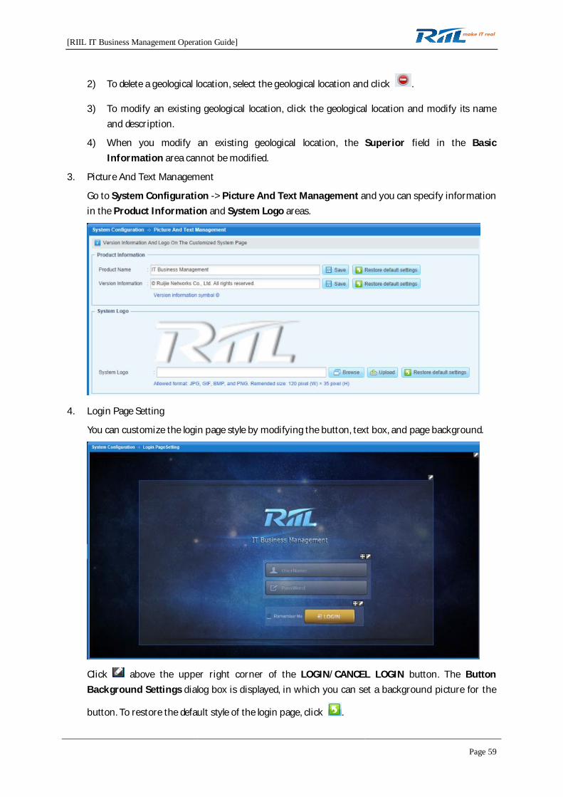
3. Picture And Text Management
Go to System Configuration -> Picture And Text Management and you can specify informationin the Product Information and System Logo areas.
4. Login Page Setting
You can customize the login page style by modifying the button, text box, and page background.
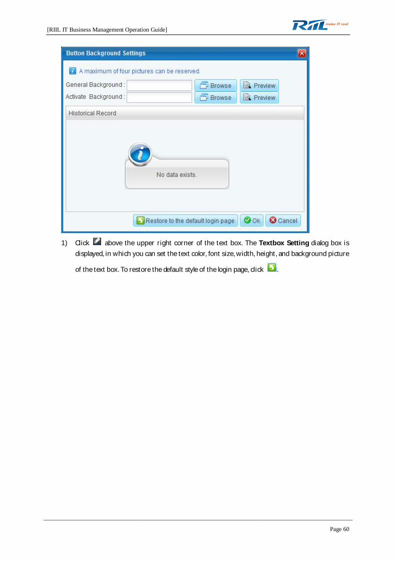
Click above the upper right corner of the LOGIN/CANCEL LOGIN button. The ButtonBackground Settings dialog box is displayed, in which you can set a background picture for the
button. To restore the default style of the login page, click .
[RIIL IT Business Management Operation Guide]
Page 60
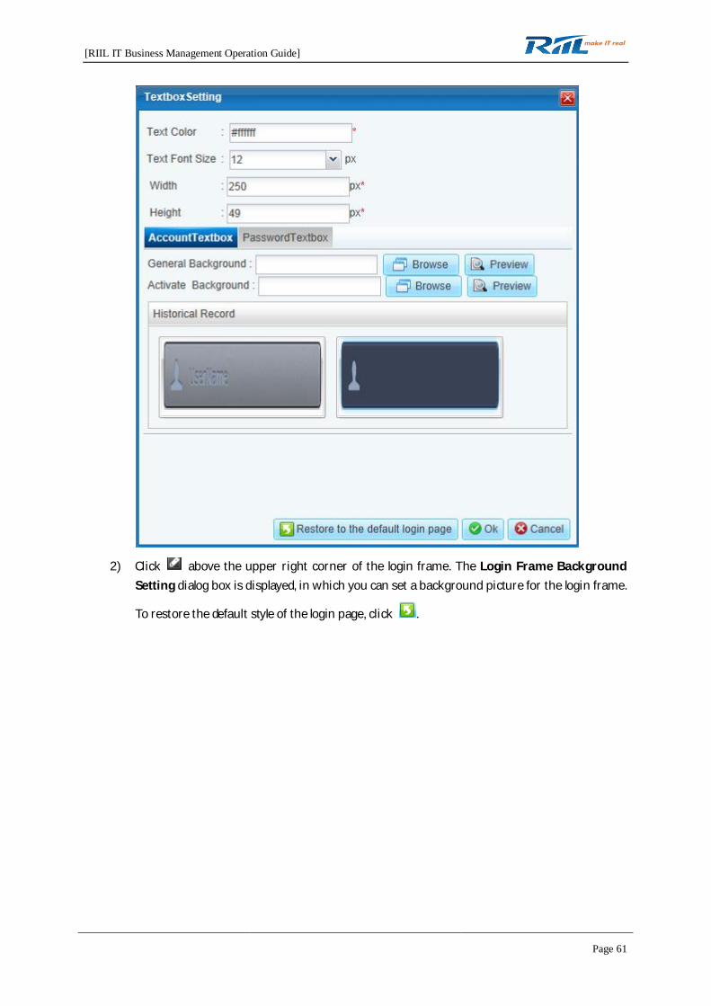
1) Click above the upper right corner of the text box. The Textbox Setting dialog box isdisplayed, in which you can set the text color, font size, width, height, and background picture
of the text box. To restore the default style of the login page, click .
[RIIL IT Business Management Operation Guide]
Page 61
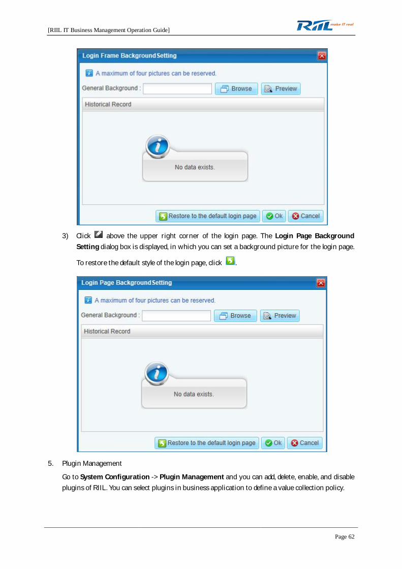
2) Click above the upper right corner of the login frame. The Login Frame BackgroundSetting dialog box is displayed, in which you can set a background picture for the login frame.
To restore the default style of the login page, click .
[RIIL IT Business Management Operation Guide]
Page 62
3) Click above the upper right corner of the login page. The Login Page BackgroundSetting dialog box is displayed, in which you can set a background picture for the login page.
To restore the default style of the login page, click .
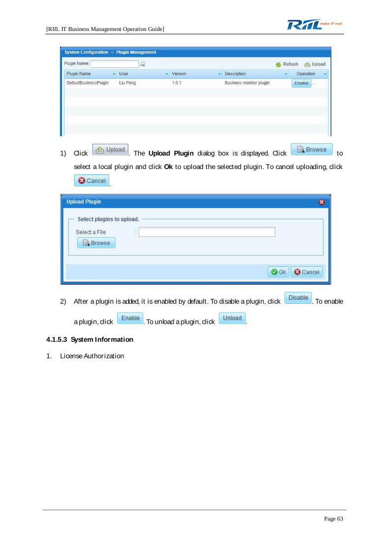
5. Plugin Management
Go to System Configuration -> Plugin Management and you can add, delete, enable, and disableplugins of RIIL. You can select plugins in business application to define a value collection policy.
[RIIL IT Business Management Operation Guide]
Page 63
1) Click . The Upload Plugin dialog box is displayed. Click to
select a local plugin and click Ok to upload the selected plugin. To cancel uploading, click
.
2) After a plugin is added, it is enabled by default. To disable a plugin, click . To enable
a plugin, click . To unload a plugin, click .
4.1.5.3 System Information
1. License Authorization

[RIIL IT Business Management Operation Guide]
Page 64
2. Logs & Configuration
The System Configuration -> Log & Configuration page contains two columns: Packet andOperation.
You can set the log display level. Click an item in the Operation column and the corresponding loglevel is red, indicating that only logs above this log level are recorded.
3. User Sessions
4. System
[RIIL IT Business Management Operation Guide]
Page 65
4.1.5.4 External System Integration
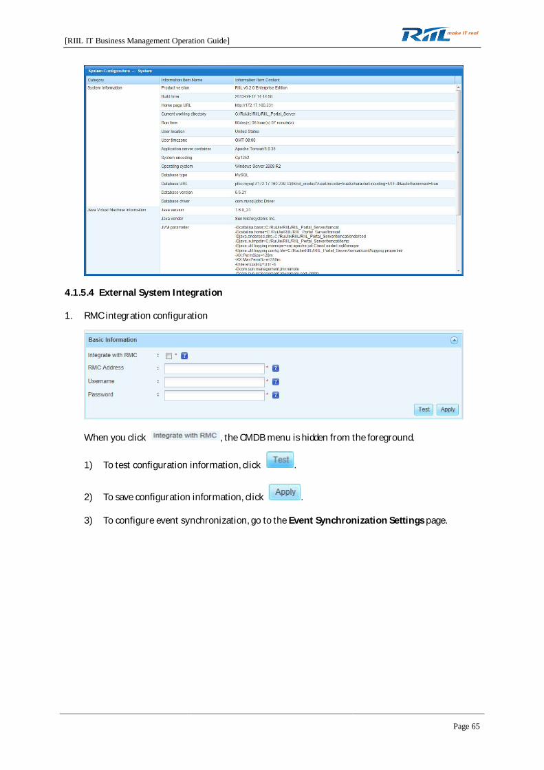
1. RMC integration configuration
When you click , the CMDB menu is hidden from the foreground.
1) To test configuration information, click .
2) To save configuration information, click .
3) To configure event synchronization, go to the Event Synchronization Settings page.

[RIIL IT Business Management Operation Guide]
Page 66
4) To save RMC synchronization information, click .
2. SNC integration configuration
4.2 Homepage
The homepage of RIIL displays the Business Services, Event Console, Network Topology, OverallBusiness Services, Resource Management, Knowledge Base, Network Traffic Analysis Center,and Manage Wireless panels using curtain wall snapshot.
[RIIL IT Business Management Operation Guide]
Page 67
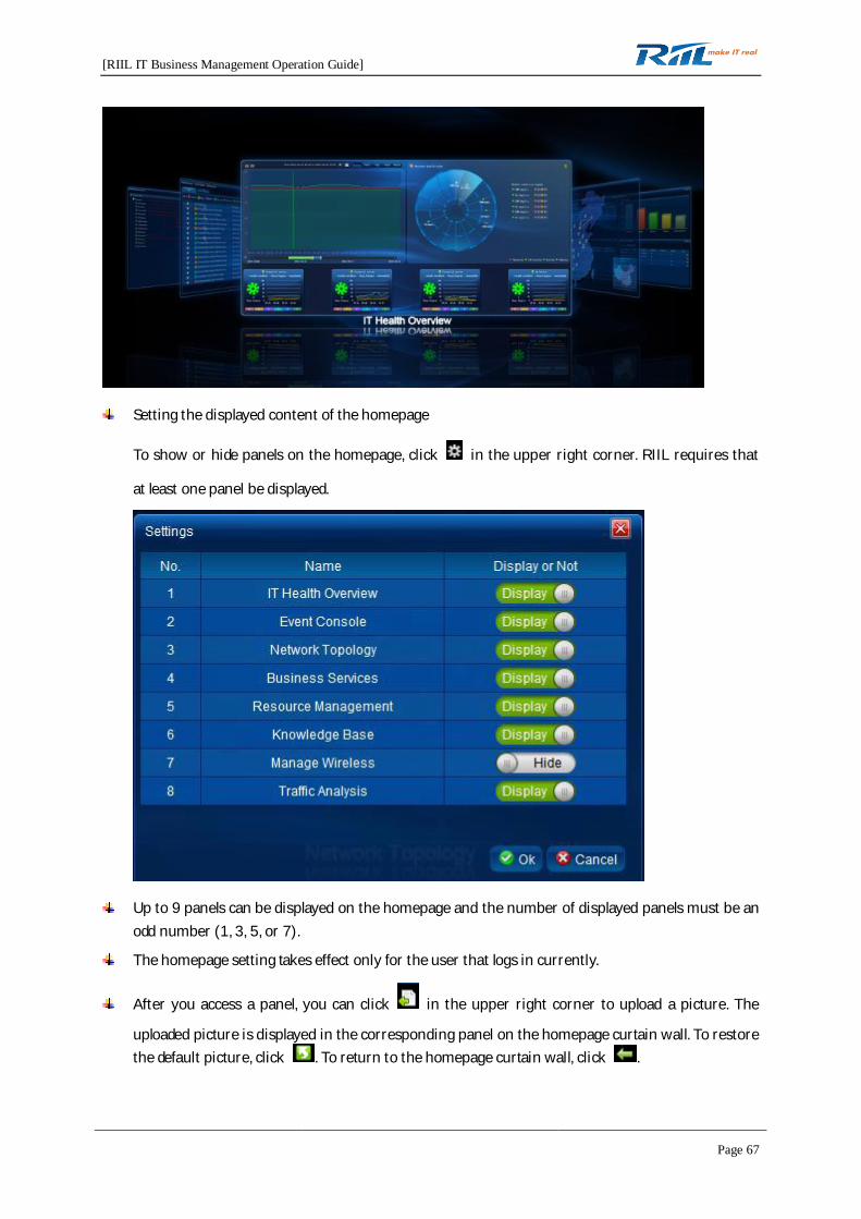
Setting the displayed content of the homepage
To show or hide panels on the homepage, click in the upper right corner. RIIL requires that
at least one panel be displayed.
Up to 9 panels can be displayed on the homepage and the number of displayed panels must be anodd number (1, 3, 5, or 7).
The homepage setting takes effect only for the user that logs in currently.
After you access a panel, you can click in the upper right corner to upload a picture. The
uploaded picture is displayed in the corresponding panel on the homepage curtain wall. To restorethe default picture, click . To return to the homepage curtain wall, click .

[RIIL IT Business Management Operation Guide]
Page 68
4.3 IT Health Index
You can perform health index setting, warning threshold setting, and health index analysis.
4.3.1 Health Index Setting
1. Setting the resources or business applications that will be added to health indexing
1) Click . The Health Index Setting dialog box is displayed, in which you can addresources or business applications to health indexing.

[RIIL IT Business Management Operation Guide]
Page 69
2) Set the weights of resources or business applications. You can click to set
weights in batches.
2. Only the system administrator has the permission to add resources to health indexing and set theweights of the added resources.
3. The weight of a new device is 0 by default. For rule monitoring, see the weight rule setting ofbusiness applications.
4.3.2 Warning Threshold Setting
1. Setting the warning threshold of health indexes
1) Click . The Warning Threshold dialog box is displayed. Drag the arrow or click a point ofthe scale to change the threshold value.
2) This operation can only be performed by the system administrator.
4.3.3 Health Index Analysis
1. Prerequisites for the occurrence of a broken line in the health index analysis diagram:
Resources or business applications have been added to health indexing. The correspondingbutton is .
[RIIL IT Business Management Operation Guide]
Page 70
The warning threshold of health indexes has been set. The corresponding button is .
The end time for analysis has been set. The corresponding button is .
2. Health diagram resetting
To reset the health diagram, click . The end time is the current time of the RIIL server.
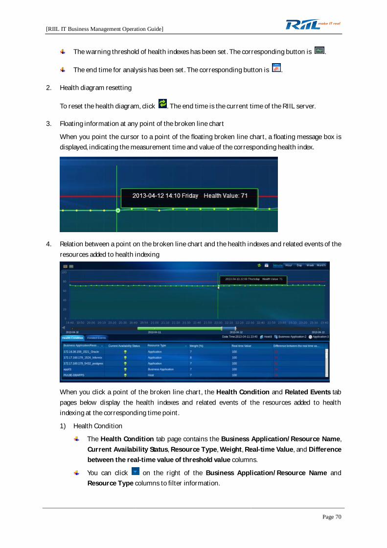
3. Floating information at any point of the broken line chart
When you point the cursor to a point of the floating broken line chart, a floating message box isdisplayed, indicating the measurement time and value of the corresponding health index.
4. Relation between a point on the broken line chart and the health indexes and related events of theresources added to health indexing
When you click a point of the broken line chart, the Health Condition and Related Events tabpages below display the health indexes and related events of the resources added to healthindexing at the corresponding time point.
1) Health Condition
The Health Condition tab page contains the Business Application/Resource Name,Current Availability Status, Resource Type, Weight, Real-time Value, and Differencebetween the real-time value of threshold value columns.
You can click on the right of the Business Application/Resource Name andResource Type columns to filter information.
[RIIL IT Business Management Operation Guide]
Page 71
You can sort information in the Current Availability Status, Resource Type, Weight,Real-time Value, and Difference between the real-time value of threshold valuecolumns.
You can click an item in the Business Application/Resource Name column and viewthe Resource Details page of the corresponding business application or resource. Youneed to have the appropriate permission to view resource details.
2) Related Events
The Related Events tab page displays the events related to the resources or businessapplications added to health indexing at the corresponding time point.
4.4 Business Service
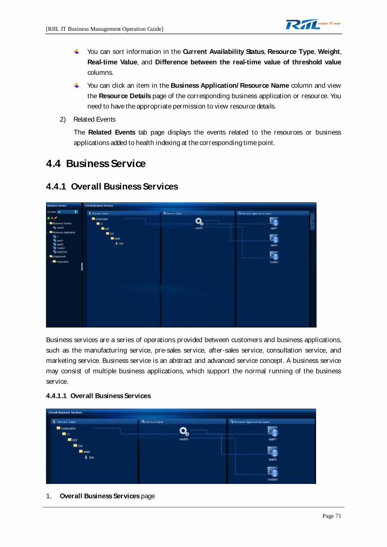
4.4.1 Overall Business Services
Business services are a series of operations provided between customers and business applications,such as the manufacturing service, pre-sales service, after-sales service, consultation service, andmarketing service. Business service is an abstract and advanced service concept. A business servicemay consist of multiple business applications, which support the normal running of the businessservice.
4.4.1.1 Overall Business Services
1. Overall Business Services page

[RIIL IT Business Management Operation Guide]
Page 72
When you access the Overall Business Services page, you can view the actual businessrelationships among the customer layer, service layer, and business application layer.
1) When you click an icon on the Overall Business Services page, you can view all lines andpeer-end icons related to the icon. For example, when you click ser001, you can view thefollowing figure.
2) When you point the cursor to the icon of a layer, you can view the floating information of theicon.
Floating information of the business application layer:
Floating information of the service layer:
Floating information of the customer layer:
[RIIL IT Business Management Operation Guide]
Page 73
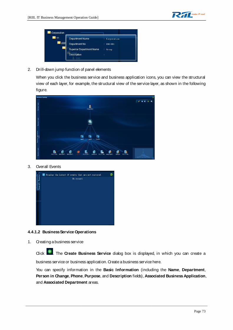
2. Drill-down jump function of panel elements
When you click the business service and business application icons, you can view the structuralview of each layer, for example, the structural view of the service layer, as shown in the followingfigure.
3. Overall Events
4.4.1.2 Business Service Operations
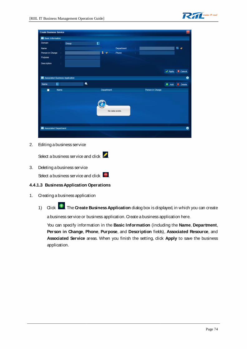
1. Creating a business service
Click . The Create Business Service dialog box is displayed, in which you can create a
business service or business application. Create a business service here.
You can specify information in the Basic Information (including the Name, Department,Person in Change, Phone, Purpose, and Description fields), Associated Business Application,and Associated Department areas.
[RIIL IT Business Management Operation Guide]
Page 74
2. Editing a business service
Select a business service and click .
3. Deleting a business service
Select a business service and click .
4.4.1.3 Business Application Operations
1. Creating a business application
1) Click . The Create Business Application dialog box is displayed, in which you can create
a business service or business application. Create a business application here.
You can specify information in the Basic Information (including the Name, Department,Person in Change, Phone, Purpose, and Description fields), Associated Resource, andAssociated Service areas. When you finish the setting, click Apply to save the businessapplication.

[RIIL IT Business Management Operation Guide]
Page 75
2) In the Associated Resource area, add resources, click Average Value, and then click Apply.
3) To delete a resource to be bound, select the resource and click Delete.
4) In the Associated Service area, add available business services.
5) When you select a plugin, the Parameter tab page is displayed. On this page, select PORT orURL, specify necessary information, and click Apply. You cannot perform operations onboth the Parameter and Availability Status tab pages at the same time.
[RIIL IT Business Management Operation Guide]
Page 76
2. Editing a business application
Select a business application and click .
3. Deleting a business application
Select a business application and click .
4.4.1.4 Business Topology
1. Explorer view
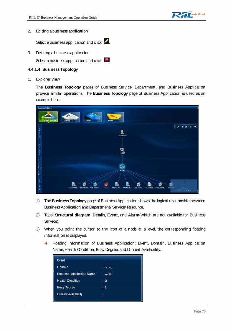
The Business Topology pages of Business Service, Department, and Business Applicationprovide similar operations. The Business Topology page of Business Application is used as anexample here.
1) The Business Topology page of Business Application shows the logical relationship betweenBusiness Application and Department/Service/Resource.
2) Tabs: Structural diagram, Details, Event, and Alarm(which are not available for BusinessService)
3) When you point the cursor to the icon of a node at a level, the corresponding floatinginformation is displayed.
Floating information of Business Application: Event, Domain, Business ApplicationName, Health Condition, Busy Degree, and Current Availability.

[RIIL IT Business Management Operation Guide]
Page 77
Floating information of Business Service: Domain, Department, Person in Charge, Phone,Purpose, Description, and Business Service Name.
Floating information of Department: Department Name, Department No, SuperiorDepartment Name, and Description.
Floating information of Resource: Event, Resource Name, Resource Type, IP Address,Health Condition, Busy Degree, and Current Availability.
4) The icon of the current business application (business service or department) is highlighted.
5) The toolbar of the Business Topology page contains the Edit View, Normal size, Fitwindow, Refresh, and Node search buttons.
Edit View: used to switch to the edit view (this button is not available on the BusinessTopology page of Department)
Normal size: used to display the structural diagram in its actual size
Fit window: used to fit the structural diagram to the size of the window
Refresh: used to refresh the structural diagram
Node search: used to search for a node in the structural diagram
[RIIL IT Business Management Operation Guide]
Page 78
6) Viewing availability configuration and weight rules: Right-click the business applicationtopology. A short-cut menu is displayed, which contains the following options:
Availability configuration: Select this option and you can view the resource relationship ofthe business application.
Weight rule: Select this option and you can view the weight rule information of the businessapplication.
2. Edit view
1) The edit view is not available for Department, which has only the explorer view.
2) Only the system administrator and domain administrator have the permission to draw astructural diagram.
3) The node of the current business application is highlighted.
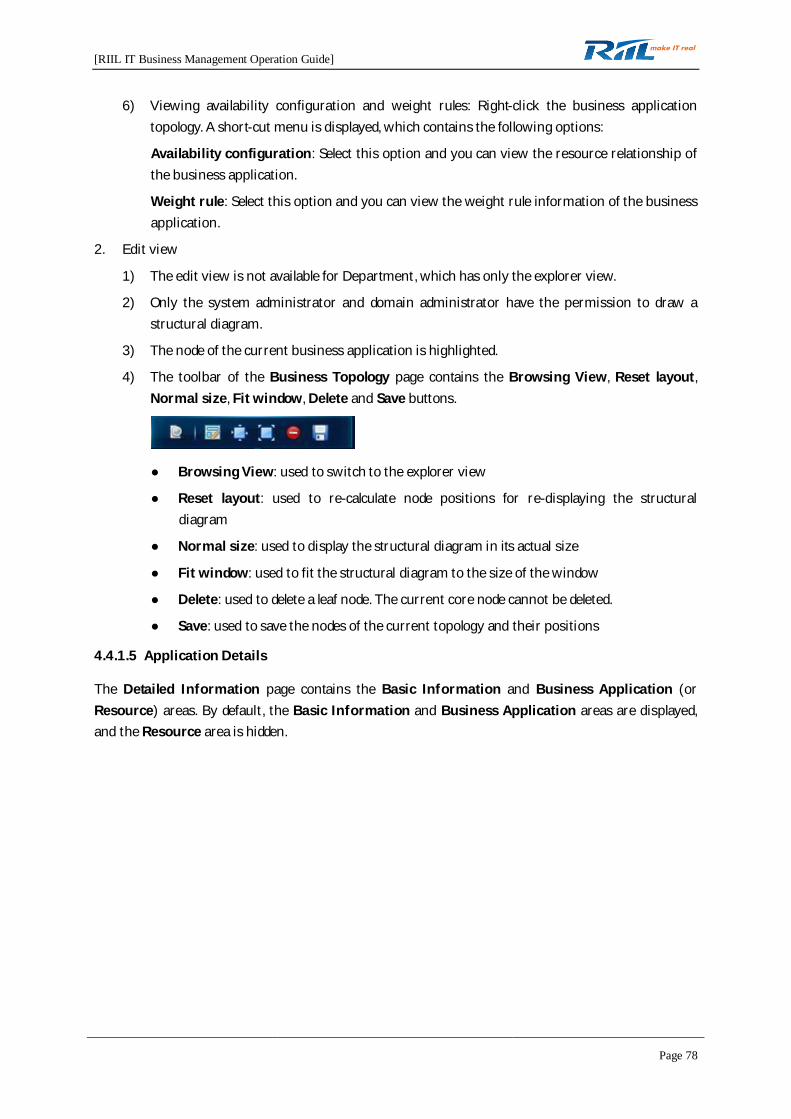
4) The toolbar of the Business Topology page contains the Browsing View, Reset layout,Normal size, Fit window, Delete and Save buttons.
Browsing View: used to switch to the explorer view
Reset layout: used to re-calculate node positions for re-displaying the structuraldiagram
Normal size: used to display the structural diagram in its actual size
Fit window: used to fit the structural diagram to the size of the window
Delete: used to delete a leaf node. The current core node cannot be deleted.
Save: used to save the nodes of the current topology and their positions
4.4.1.5 Application Details
The Detailed Information page contains the Basic Information and Business Application (orResource) areas. By default, the Basic Information and Business Application areas are displayed,and the Resource area is hidden.
[RIIL IT Business Management Operation Guide]
Page 79
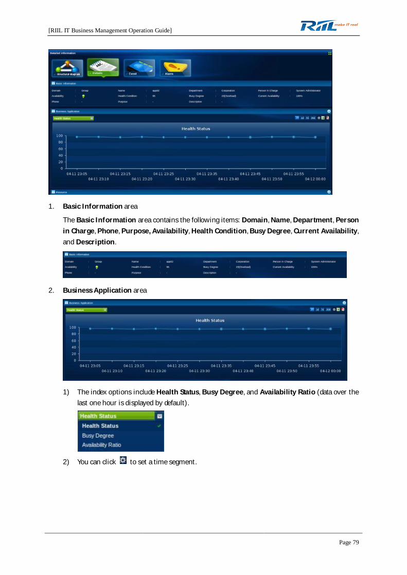
1. Basic Information area
The Basic Information area contains the following items: Domain, Name, Department, Personin Charge, Phone, Purpose, Availability, Health Condition, Busy Degree, Current Availability,and Description.
2. Business Application area
1) The index options include Health Status, Busy Degree, and Availability Ratio (data over thelast one hour is displayed by default).
2) You can click to set a time segment.

[RIIL IT Business Management Operation Guide]
Page 80
3) Data can be displayed by 1h, 1d, 7d, or 30d and exported into an Excel file or a PDF file.
4) When you click a data point on the curve, you can view information of the correspondingvalue.
3. Resource area
1) Click . The Resource area is displayed. No data exists in this area by default.
2) To view analysis data, select a resource under Select resource on the left and click 1h, 1d, 7d,or 30d, or click to set a time segment.
3) The index options include Health Status, Busy Degree, Availability Ratio, BreakdownTimes, Downtime (minutes), MTTR, and MTBF.
[RIIL IT Business Management Operation Guide]
Page 81
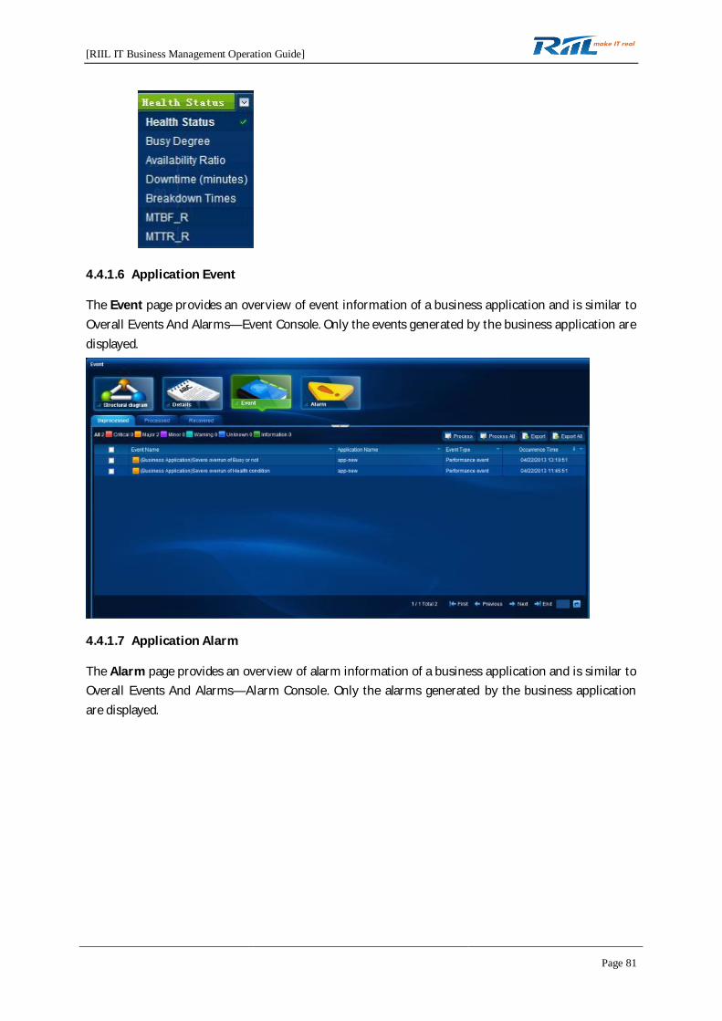
4.4.1.6 Application Event
The Event page provides an overview of event information of a business application and is similar toOverall Events And Alarms—Event Console. Only the events generated by the business application aredisplayed.
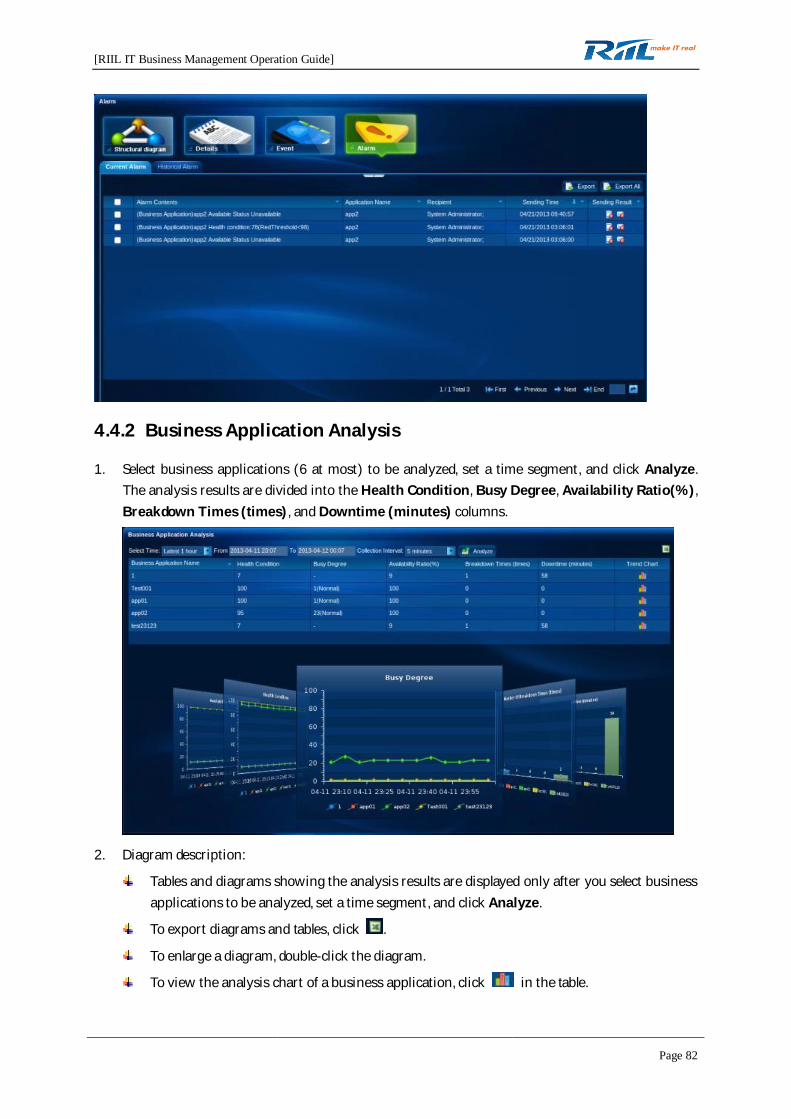
4.4.1.7 Application Alarm
The Alarm page provides an overview of alarm information of a business application and is similar toOverall Events And Alarms—Alarm Console. Only the alarms generated by the business applicationare displayed.
[RIIL IT Business Management Operation Guide]
Page 82
4.4.2 Business Application Analysis
1. Select business applications (6 at most) to be analyzed, set a time segment, and click Analyze.The analysis results are divided into the Health Condition, Busy Degree, Availability Ratio(%),Breakdown Times (times), and Downtime (minutes) columns.
2. Diagram description:
Tables and diagrams showing the analysis results are displayed only after you select businessapplications to be analyzed, set a time segment, and click Analyze.
To export diagrams and tables, click .
To enlarge a diagram, double-click the diagram.
To view the analysis chart of a business application, click in the table.
[RIIL IT Business Management Operation Guide]
Page 83
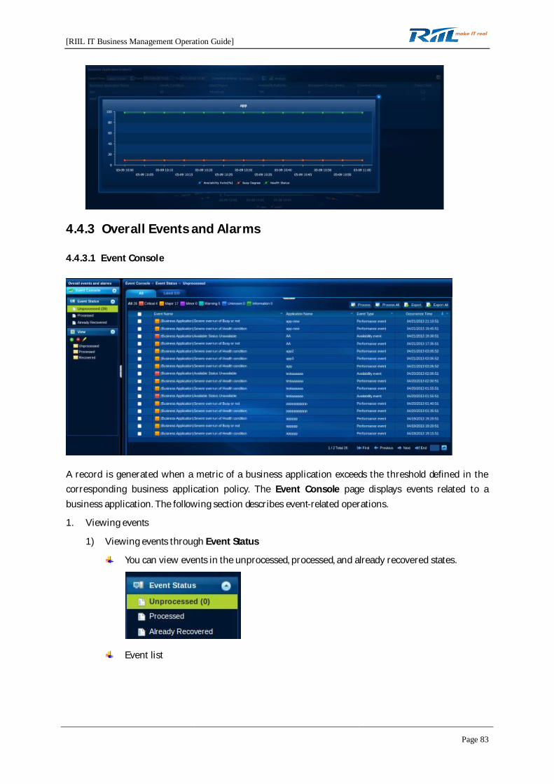
4.4.3 Overall Events and Alarms
4.4.3.1 Event Console
A record is generated when a metric of a business application exceeds the threshold defined in thecorresponding business application policy. The Event Console page displays events related to abusiness application. The following section describes event-related operations.
1. Viewing events
1) Viewing events through Event Status
You can view events in the unprocessed, processed, and already recovered states.
Event list

[RIIL IT Business Management Operation Guide]
Page 84
The event list consists of the Event Name, Application Name, Event Type, and OccurrenceTime columns.
Click an event name to view event details.
You can view events by event severity, including critical, major, minor, warning, unknown,and information.
2) Viewing events in the View area
In the View area, you can filter events to obtain unprocessed, processed, or recovered eventsbased on certain criteria.
2. Processing events
You can process one or all events.
To process an event, select the event and click . The processed event is added to the
processed event list.
To process all events, click . After being processed, all events are added to the
processed event list.
3. Exporting events
You can export one or all events.
Select an event and click . The selected event is exported into an EXCEL file.
[RIIL IT Business Management Operation Guide]
Page 85
To export all events, click .
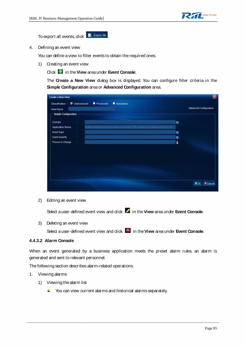
4. Defining an event view
You can define a view to filter events to obtain the required ones.
1) Creating an event view
Click in the View area under Event Console.
The Create a New View dialog box is displayed. You can configure filter criteria in theSimple Configuration area or Advanced Configuration area.
2) Editing an event view
Select a user-defined event view and click in the View area under Event Console.
3) Deleting an event view
Select a user-defined event view and click in the View area under Event Console.
4.4.3.2 Alarm Console
When an event generated by a business application meets the preset alarm rules, an alarm isgenerated and sent to relevant personnel.
The following section describes alarm-related operations.
1. Viewing alarms
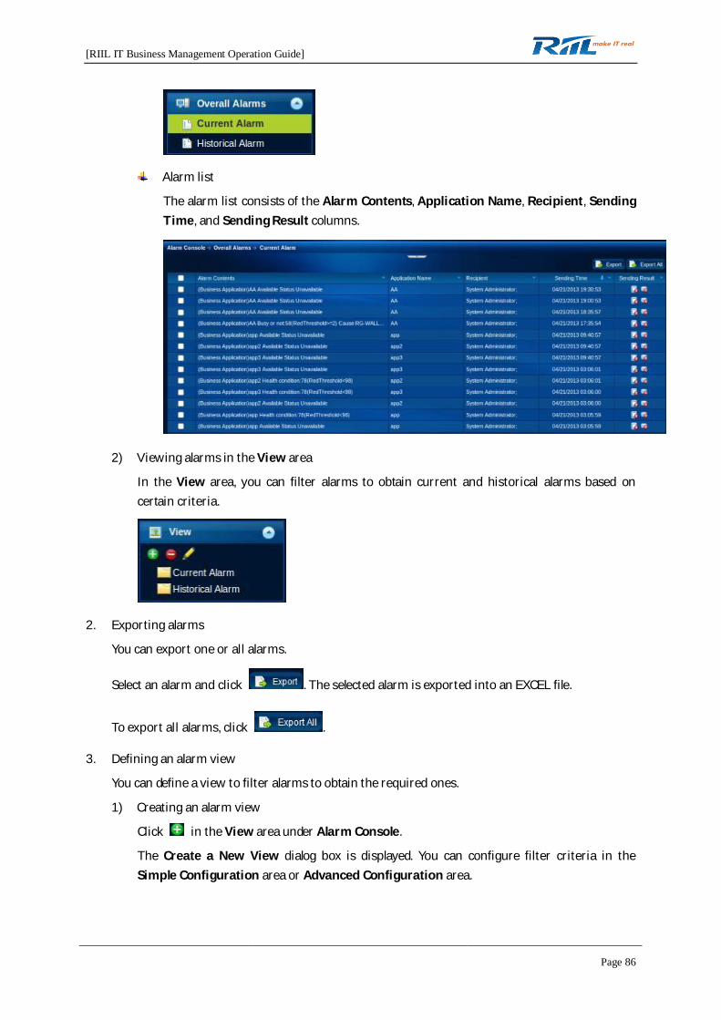
1) Viewing the alarm list
You can view current alarms and historical alarms separately.
[RIIL IT Business Management Operation Guide]
Page 86
Alarm list
The alarm list consists of the Alarm Contents, Application Name, Recipient, SendingTime, and Sending Result columns.
2) Viewing alarms in the View area
In the View area, you can filter alarms to obtain current and historical alarms based oncertain criteria.
2. Exporting alarms
You can export one or all alarms.
Select an alarm and click . The selected alarm is exported into an EXCEL file.
To export all alarms, click .
3. Defining an alarm view
You can define a view to filter alarms to obtain the required ones.
1) Creating an alarm view
Click in the View area under Alarm Console.
The Create a New View dialog box is displayed. You can configure filter criteria in theSimple Configuration area or Advanced Configuration area.

[RIIL IT Business Management Operation Guide]
Page 87
2) Editing an alarm view
Select a user-defined alarm view and click in the View area under Alarm Console.
3) Deleting a view
Select a user-defined alarm view and click in the View area under Alarm Console.
4.4.4 Policy Configuration
4.4.4.1 Policy Setting
A business application policy defines the metrics, events, and alarms related to a business application.A business application can monitor its metrics and generate events and alarms only after it is assignedwith a business application policy. RIIL provides a default business application policy.
1. Creating a policy
Click and specify basic information in the dialog box displayed. After a policy is created, the
Resource Relation, Metric Configuration, Event Configuration, and Alarm Configuration tabpages are displayed.
You can create a policy using either of the following methods:
Click in the toolbar.
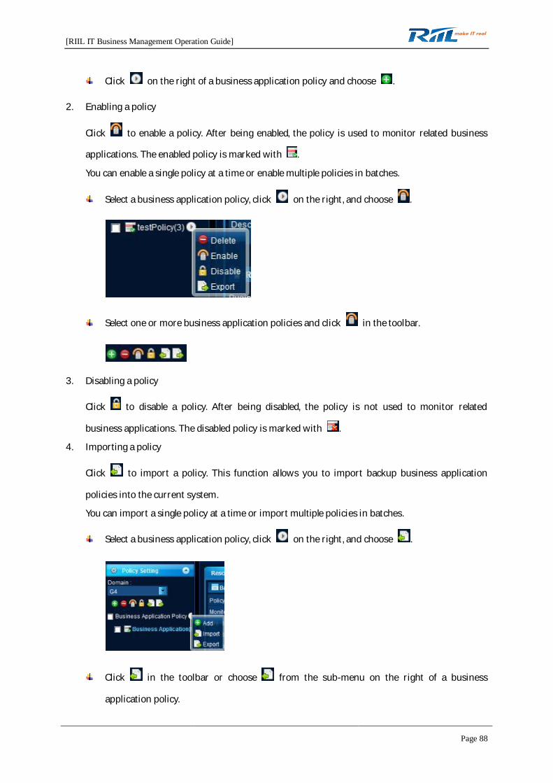
[RIIL IT Business Management Operation Guide]
Page 88
Click on the right of a business application policy and choose .
2. Enabling a policy
Click to enable a policy. After being enabled, the policy is used to monitor related business
applications. The enabled policy is marked with .
You can enable a single policy at a time or enable multiple policies in batches.
Select a business application policy, click on the right, and choose .
Select one or more business application policies and click in the toolbar.
3. Disabling a policy
Click to disable a policy. After being disabled, the policy is not used to monitor related
business applications. The disabled policy is marked with .
4. Importing a policy
Click to import a policy. This function allows you to import backup business application
policies into the current system.
You can import a single policy at a time or import multiple policies in batches.
Select a business application policy, click on the right, and choose .
Click in the toolbar or choose from the sub-menu on the right of a business
application policy.

[RIIL IT Business Management Operation Guide]
Page 89
Toolbar:
Sub-menu:
5. Exporting a policy
Click to export a policy. This function allows you to back up business application policies in
the current system.
You can export a single policy at a time or export multiple policies in batches.
Select a business application policy, click on the right, and choose .
Select one or more business application policies and click in the toolbar or choose
from the sub-menu on the right of the selected policy.
Toolbar:
Sub-menu:
6. Deleting a policy
Click to delete a policy. A prompt is displayed for your confirmation on the deletion. You
cannot delete the default policy.
7. Editing a policy

[RIIL IT Business Management Operation Guide]
Page 90
Click the name of an existing policy to edit the policy. You can specify information on theResource Relation, Metric Configuration, Event Configuration, and Alarm Configuration tabpages.
1) Resource Relation
On the Resource Relation tab page, you can set the resources to be monitored using abusiness application policy.
2) Metric Configuration
On the Resource Configuration tab page, you can set the resource metrics to be monitoredusing a business application policy.
3) Event Configuration
On the Event Configuration tab page, you can set the types of events generated by theresources monitored using a business application policy. Those events are classified intoavailability events and performance events.

[RIIL IT Business Management Operation Guide]
Page 91
4) Alarm Configuration
4.4.4.2 Permission Setting
Permission control is available for business applications. After a business application is added to aworkgroup, only users in the workgroup have access to the business application.
1. Adding a business application to a workgroup
Click Add. The Add Business Application window is displayed, in which you can add a businessapplication to a workgroup.
2. Deleting a business application from a workgroup
Select a business application and click Delete.
Note: The default workgroup does not support the adding or deleting operation.
4.5 Event and Alarm Center
4.5.1 Event Console
The Event Console page displays events related to various resources (including hosts, network devices,storage devices, business applications, links, and equipment room elements). When you access theevent and alarm center, the Unprocessed page is displayed by default.
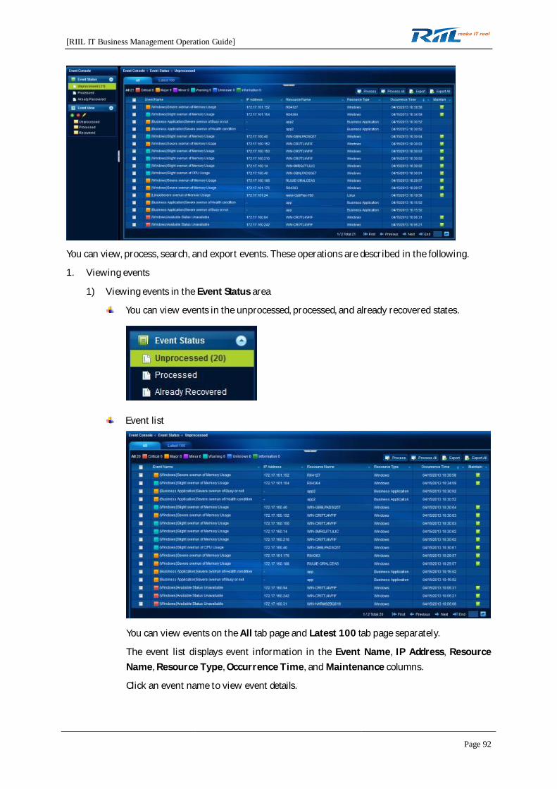
[RIIL IT Business Management Operation Guide]
Page 92
You can view, process, search, and export events. These operations are described in the following.
1. Viewing events
1) Viewing events in the Event Status area
You can view events in the unprocessed, processed, and already recovered states.
Event list
You can view events on the All tab page and Latest 100 tab page separately.
The event list displays event information in the Event Name, IP Address, ResourceName, Resource Type, Occurrence Time, and Maintenance columns.
Click an event name to view event details.
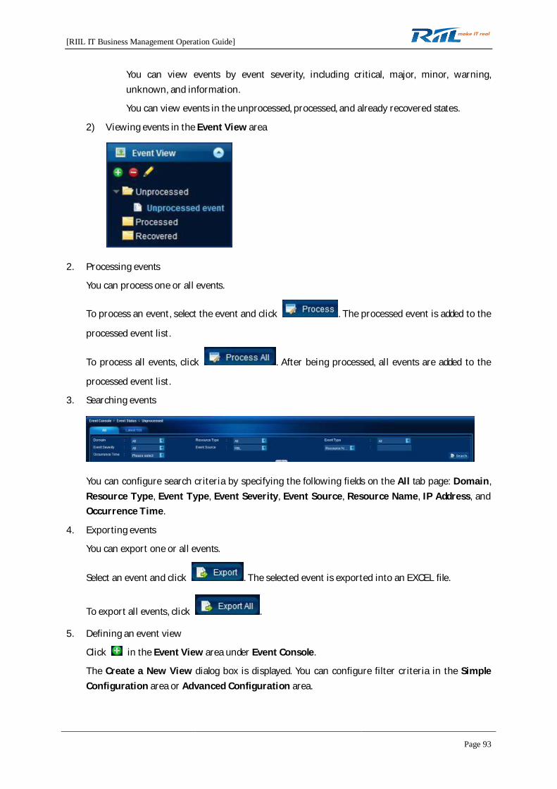
[RIIL IT Business Management Operation Guide]
Page 93
You can view events by event severity, including critical, major, minor, warning,unknown, and information.
You can view events in the unprocessed, processed, and already recovered states.
2) Viewing events in the Event View area
2. Processing events
You can process one or all events.
To process an event, select the event and click . The processed event is added to the
processed event list.
To process all events, click . After being processed, all events are added to the
processed event list.
3. Searching events
You can configure search criteria by specifying the following fields on the All tab page: Domain,Resource Type, Event Type, Event Severity, Event Source, Resource Name, IP Address, andOccurrence Time.
4. Exporting events
You can export one or all events.
Select an event and click . The selected event is exported into an EXCEL file.
To export all events, click .
5. Defining an event view
Click in the Event View area under Event Console.
The Create a New View dialog box is displayed. You can configure filter criteria in the SimpleConfiguration area or Advanced Configuration area.
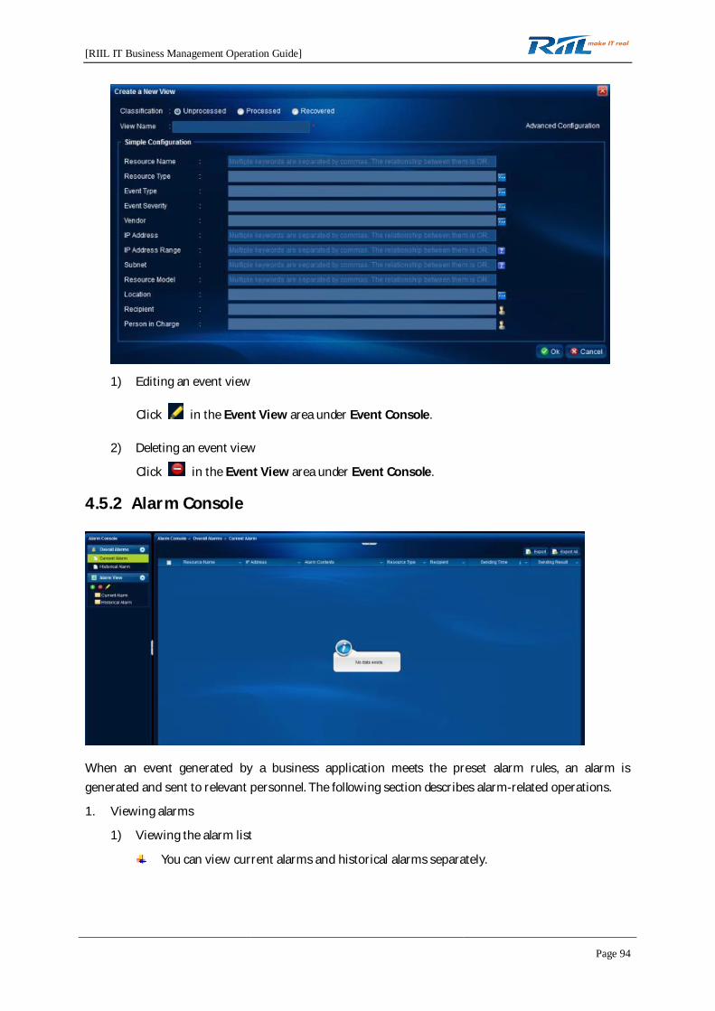
[RIIL IT Business Management Operation Guide]
Page 94
1) Editing an event view
Click in the Event View area under Event Console.
2) Deleting an event view
Click in the Event View area under Event Console.
4.5.2 Alarm Console
When an event generated by a business application meets the preset alarm rules, an alarm isgenerated and sent to relevant personnel. The following section describes alarm-related operations.
1. Viewing alarms
1) Viewing the alarm list
You can view current alarms and historical alarms separately.
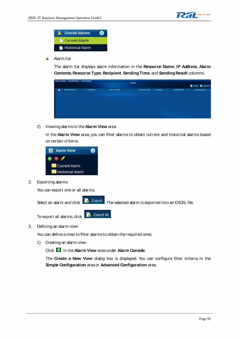
[RIIL IT Business Management Operation Guide]
Page 95
Alarm list
The alarm list displays alarm information in the Resource Name, IP Address, AlarmContents, Resource Type, Recipient, Sending Time, and Sending Result columns.
2) Viewing alarms in the Alarm View area
In the Alarm View area, you can filter alarms to obtain current and historical alarms basedon certain criteria.
2. Exporting alarms
You can export one or all alarms.
Select an alarm and click . The selected alarm is exported into an EXCEL file.
To export all alarms, click .
3. Defining an alarm view
You can define a view to filter alarms to obtain the required ones.
1) Creating an alarm view
Click in the Alarm View area under Alarm Console.
The Create a New View dialog box is displayed. You can configure filter criteria in theSimple Configuration area or Advanced Configuration area.
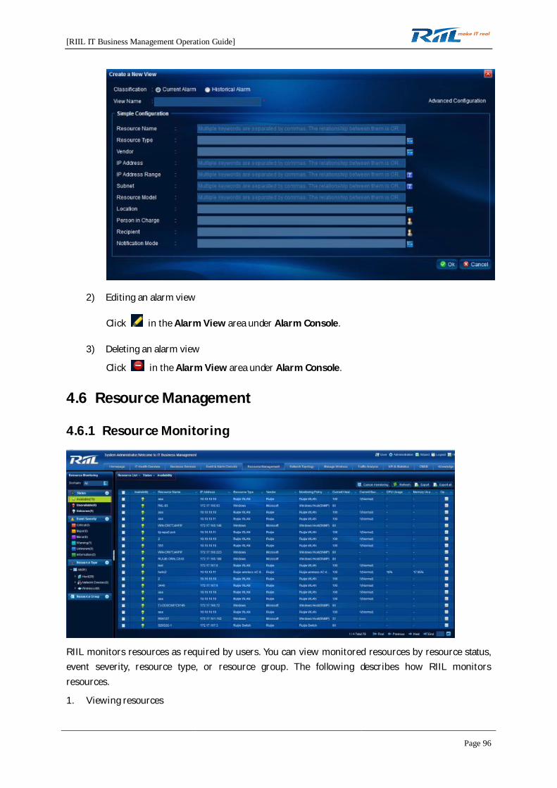
[RIIL IT Business Management Operation Guide]
Page 96
2) Editing an alarm view
Click in the Alarm View area under Alarm Console.
3) Deleting an alarm view
Click in the Alarm View area under Alarm Console.
4.6 Resource Management
4.6.1 Resource Monitoring
RIIL monitors resources as required by users. You can view monitored resources by resource status,event severity, resource type, or resource group. The following describes how RIIL monitorsresources.
1. Viewing resources

[RIIL IT Business Management Operation Guide]
Page 97
1) By status
You can view monitored resources by status, including available, unavailable, and unknown.
2) By event severity
You can view resources by event severity. Event severities include critical, major, minor,warning, unknown, and information.
3) By resource type
You can view resources by resource type.
4) By resource group
You can view resources by resource group.
2. Add to a resource group
To facilitate resource management, you can add resources to resource groups.
The button is available only after you select a domain in
.
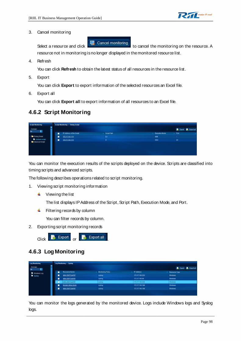
[RIIL IT Business Management Operation Guide]
Page 98
3. Cancel monitoring
Select a resource and click to cancel the monitoring on the resource. Aresource not in monitoring is no longer displayed in the monitored resource list.
4. Refresh
You can click Refresh to obtain the latest status of all resources in the resource list.
5. Export
You can click Export to export information of the selected resources an Excel file.
6. Export all
You can click Export all to export information of all resources to an Excel file.
4.6.2 Script Monitoring
You can monitor the execution results of the scripts deployed on the device. Scripts are classified intotiming scripts and advanced scripts.
The following describes operations related to script monitoring.
1. Viewing script monitoring information
Viewing the list
The list displays IP Address of the Script, Script Path, Execution Mode, and Port.
Filtering records by column
You can filter records by column.
2. Exporting script monitoring records
Click or .
4.6.3 Log Monitoring
You can monitor the logs generated by the monitored device. Logs include Windows logs and Sysloglogs.
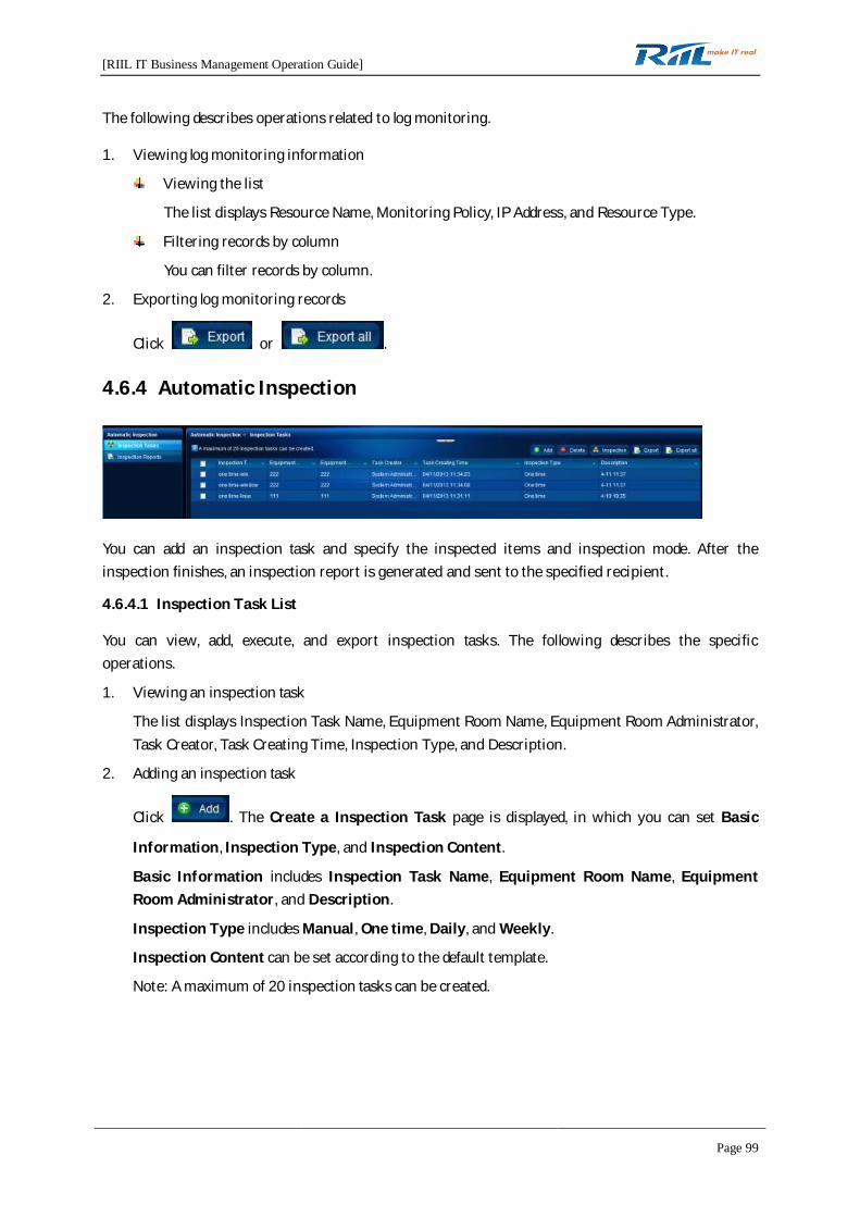
[RIIL IT Business Management Operation Guide]
Page 99
The following describes operations related to log monitoring.
1. Viewing log monitoring information
Viewing the list
The list displays Resource Name, Monitoring Policy, IP Address, and Resource Type.
Filtering records by column
You can filter records by column.
2. Exporting log monitoring records
Click or .
4.6.4 Automatic Inspection
You can add an inspection task and specify the inspected items and inspection mode. After theinspection finishes, an inspection report is generated and sent to the specified recipient.
4.6.4.1 Inspection Task List
You can view, add, execute, and export inspection tasks. The following describes the specificoperations.
1. Viewing an inspection task
The list displays Inspection Task Name, Equipment Room Name, Equipment Room Administrator,Task Creator, Task Creating Time, Inspection Type, and Description.
2. Adding an inspection task
Click . The Create a Inspection Task page is displayed, in which you can set Basic
Information, Inspection Type, and Inspection Content.
Basic Information includes Inspection Task Name, Equipment Room Name, EquipmentRoom Administrator, and Description.
Inspection Type includes Manual, One time, Daily, and Weekly.
Inspection Content can be set according to the default template.
Note: A maximum of 20 inspection tasks can be created.

[RIIL IT Business Management Operation Guide]
Page 100
3. Executing an inspection task
Select a task and click to execute the task. After the inspection finishes, an
inspection report is generated.
4. Exporting inspection tasks
Select one or more tasks and click or to export task information to an
Excel file.
5. Searching for an inspection task
You can search for the desired task by search condition.
Search conditions include Report Name, Inspection Person, Report Recipient, Report EditingPerson, Current Status, and Inspection Time.
6. Deleting an inspection task
Select a task and click to delete the selected task.
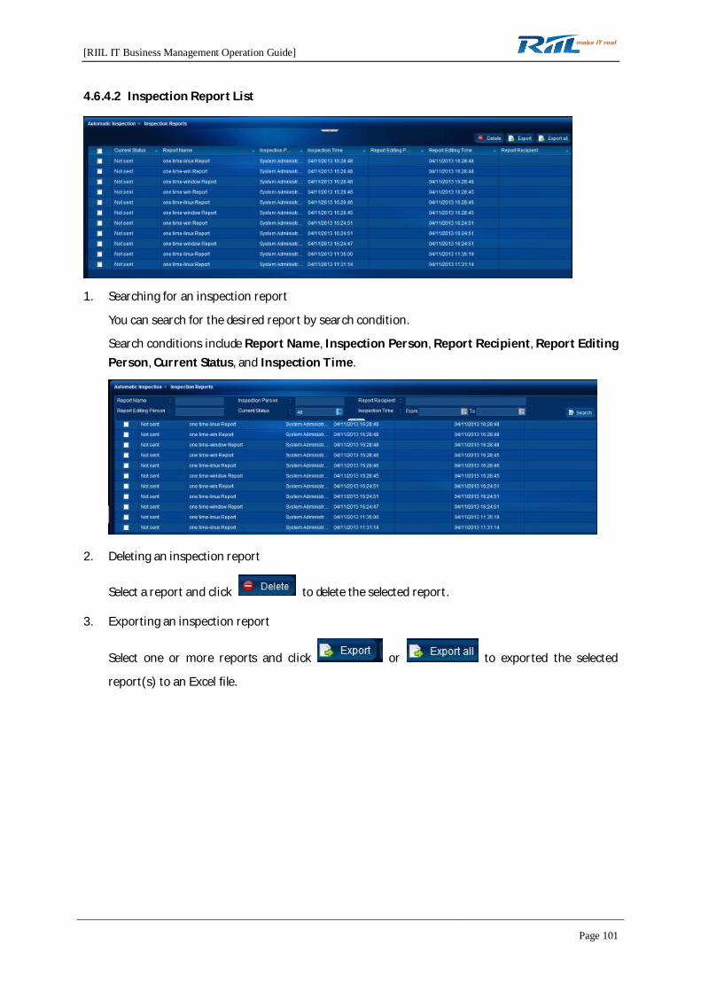
[RIIL IT Business Management Operation Guide]
Page 101
4.6.4.2 Inspection Report List
1. Searching for an inspection report
You can search for the desired report by search condition.
Search conditions include Report Name, Inspection Person, Report Recipient, Report EditingPerson, Current Status, and Inspection Time.
2. Deleting an inspection report
Select a report and click to delete the selected report.
3. Exporting an inspection report
Select one or more reports and click or to exported the selected
report(s) to an Excel file.

[RIIL IT Business Management Operation Guide]
Page 102
4.6.5 Real-time Data Analysis
You can analyze the data of hosts, network devices, network interfaces, and applications in real time.
1. Real-time host analysis
You can set the following parameters:
Collection Interval: 5 Seconds, 10 Seconds, 30 Seconds, and 60 Seconds
Metric Selection: Average CPU utilization rate and Memory utilization rate
Click to start real-time analysis on the selected host. Click to stop the
analysis.
2. Real-time network device analysis
You can set the following parameters:
Collection Interval: 5 Seconds, 10 Seconds, 30 Seconds, and 60 Seconds
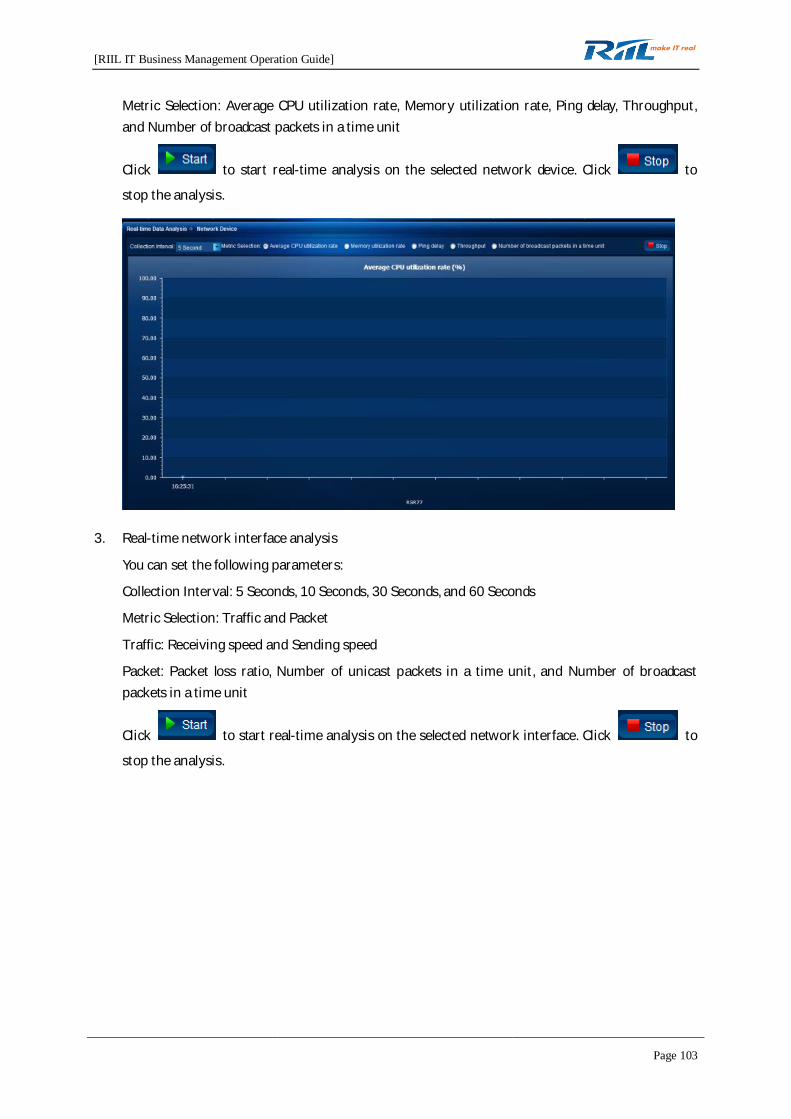
[RIIL IT Business Management Operation Guide]
Page 103
Metric Selection: Average CPU utilization rate, Memory utilization rate, Ping delay, Throughput,and Number of broadcast packets in a time unit
Click to start real-time analysis on the selected network device. Click to
stop the analysis.
3. Real-time network interface analysis
You can set the following parameters:
Collection Interval: 5 Seconds, 10 Seconds, 30 Seconds, and 60 Seconds
Metric Selection: Traffic and Packet
Traffic: Receiving speed and Sending speed
Packet: Packet loss ratio, Number of unicast packets in a time unit, and Number of broadcastpackets in a time unit
Click to start real-time analysis on the selected network interface. Click to
stop the analysis.
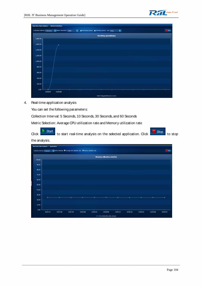
[RIIL IT Business Management Operation Guide]
Page 104
4. Real-time application analysis
You can set the following parameters:
Collection Interval: 5 Seconds, 10 Seconds, 30 Seconds, and 60 Seconds
Metric Selection: Average CPU utilization rate and Memory utilization rate
Click to start real-time analysis on the selected application. Click to stop
the analysis.

[RIIL IT Business Management Operation Guide]
Page 105
4.6.6 TOPN
1. Click . The Settings page is displayed.
1) Select the refresh frequency in .
2) Enable or disable automatic paging in
.
2. Click to refresh data.
3. Click . The Portlet Settings page is displayed.
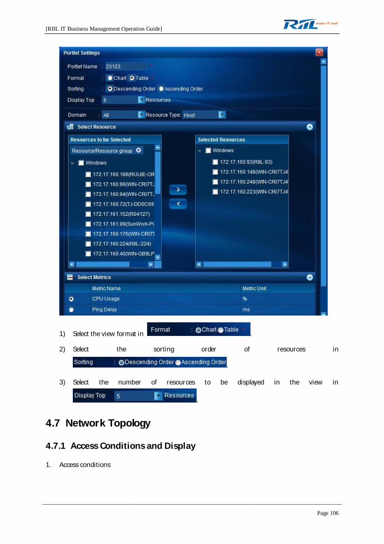
[RIIL IT Business Management Operation Guide]
Page 106
1) Select the view format in .
2) Select the sorting order of resources in
.
3) Select the number of resources to be displayed in the view in
.
4.7 Network Topology
4.7.1 Access Conditions and Display
1. Access conditions
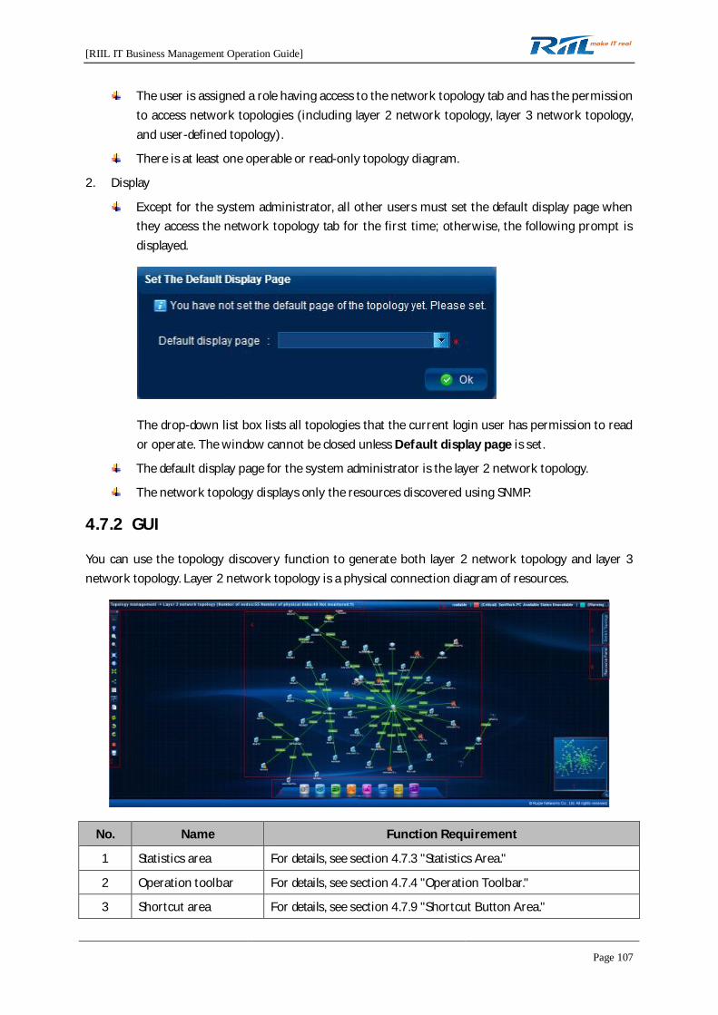
[RIIL IT Business Management Operation Guide]
Page 107
The user is assigned a role having access to the network topology tab and has the permissionto access network topologies (including layer 2 network topology, layer 3 network topology,and user-defined topology).
There is at least one operable or read-only topology diagram.
2. Display
Except for the system administrator, all other users must set the default display page whenthey access the network topology tab for the first time; otherwise, the following prompt isdisplayed.
The drop-down list box lists all topologies that the current login user has permission to reador operate. The window cannot be closed unless Default display page is set.
The default display page for the system administrator is the layer 2 network topology.
The network topology displays only the resources discovered using SNMP.
4.7.2 GUI
You can use the topology discovery function to generate both layer 2 network topology and layer 3network topology. Layer 2 network topology is a physical connection diagram of resources.
No. Name Function Requirement
1 Statistics area For details, see section 4.7.3 "Statistics Area."
2 Operation toolbar For details, see section 4.7.4 "Operation Toolbar."
3 Shortcut area For details, see section 4.7.9 "Shortcut Button Area."

[RIIL IT Business Management Operation Guide]
Page 108
No. Name Function Requirement
4 Topology area For details, see section 4.7.8 "Topology Area."
5 Topology switching For details, see section 4.7.10 "Topology Switching."
6 Resource panel For details, see section 4.7.11 "Resource Panel."
7 Thumbnail image For details, see section 4.7.5.2 "Thumbnail Image Panel."
8 Marquee view For details, see section 4.7.7 "Marquee."
4.7.3 Statistics Area
The statistics area displays "Topology management -> XXX (Number of nodes: [number] Number ofphysical links: [number] Not monitored: [number])".
XXX indicates the name of the displayed network topology.
Number of nodes indicates the number of devices in the current topology view.
Number of physical links indicates the number of physical links of the current device.
Not monitored indicates the number of unmonitored physical devices in the current topology view.
4.7.4 Operation Toolbar
Unfolded Folded
From top down, the toolbar contains the following icons: back, play, search node, zoom, fit to window,normal size, full screen, auto layout, show grid, display hidden nodes, not display hidden nodes, refresh,undo, redo, delete, and save.
Click to display or hide the toolbar.
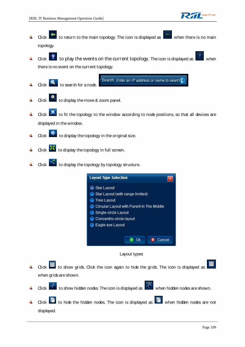
[RIIL IT Business Management Operation Guide]
Page 109
Click to return to the main topology. The icon is displayed as when there is no main
topology.
Click to play the events on the current topology. The icon is displayed as when
there is no event on the current topology.
Click to search for a node.
Click to display the move & zoom panel.
Click to fit the topology to the window according to node positions, so that all devices are
displayed in the window.
Click to display the topology in the original size.
Click to display the topology in full screen.
Click to display the topology by topology structure.
Layout types
Click to show grids. Click the icon again to hide the grids. The icon is displayed as
when grids are shown.
Click to show hidden nodes. The icon is displayed as when hidden nodes are shown.
Click to hide the hidden nodes. The icon is displayed as when hidden nodes are not
displayed.

[RIIL IT Business Management Operation Guide]
Page 110
Click to refresh the topology.
Click to undo a maximum of the latest five position changes.
Click to redo a maximum of the latest five undone changes.
Click to delete a node. This button is unavailable in the layer 3 network topology, and the icon
is displayed as .
Click to save the topology.
4.7.5 Navigation
4.7.5.1 Move & Zoom Panel
Click to display the move & zoom panel.
Click the up, down, left, or right arrow in to move the topology up, down, left, or
right.
Select and drag the topology.
Directly select the zoom size in to zoom in or out the topology.
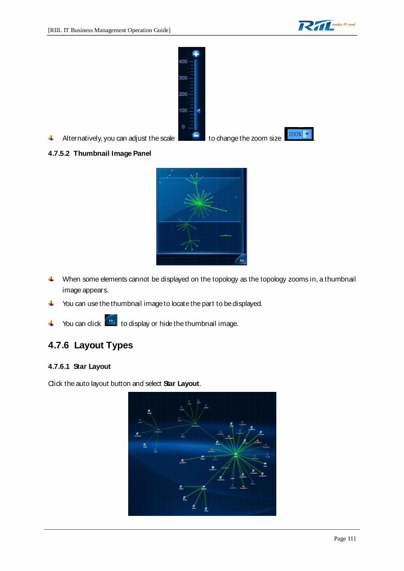
[RIIL IT Business Management Operation Guide]
Page 111
Alternatively, you can adjust the scale to change the zoom size .
4.7.5.2 Thumbnail Image Panel
When some elements cannot be displayed on the topology as the topology zooms in, a thumbnailimage appears.
You can use the thumbnail image to locate the part to be displayed.
You can click to display or hide the thumbnail image.
4.7.6 Layout Types
4.7.6.1 Star Layout
Click the auto layout button and select Star Layout.

[RIIL IT Business Management Operation Guide]
Page 112
4.7.6.2 Star Layout (with range limited)
Click the auto layout button and select Star Layout (with range limited).
4.7.6.3 Tree Layout
Select a root node.
Click the auto layout button and select Tree Layout.
4.7.6.4 Circular Layout with Parent in The Middle
Select a root node.
Click the auto layout button and select Circular Layout with Parent in The Middle.
4.7.6.5 Single-circle Layout
Click the auto layout button and select Single-circle Layout.
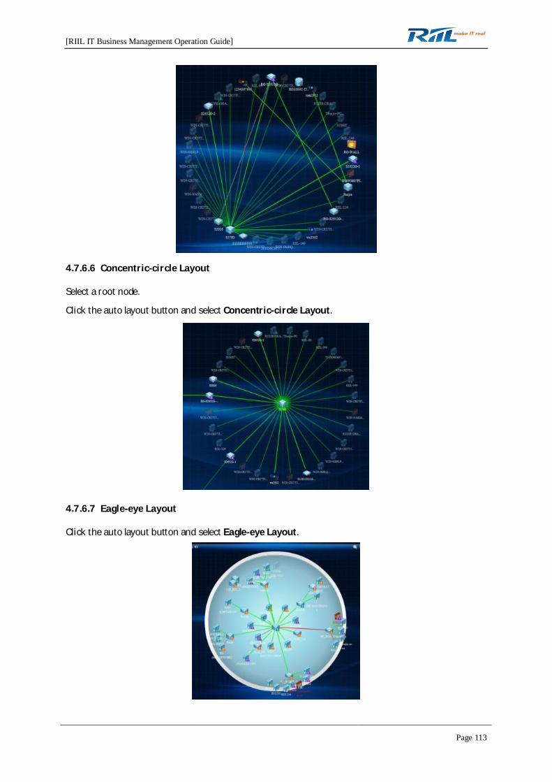
[RIIL IT Business Management Operation Guide]
Page 113
4.7.6.6 Concentric-circle Layout
Select a root node.
Click the auto layout button and select Concentric-circle Layout.
4.7.6.7 Eagle-eye Layout
Click the auto layout button and select Eagle-eye Layout.
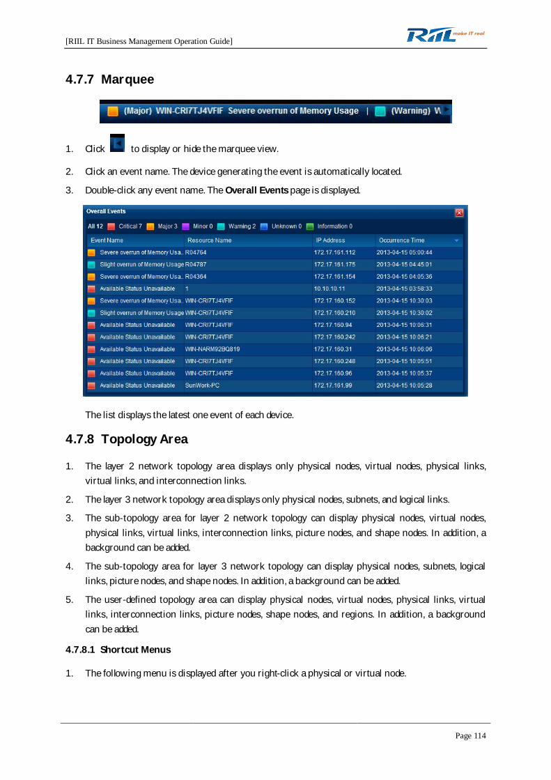
[RIIL IT Business Management Operation Guide]
Page 114
4.7.7 Marquee
1. Click to display or hide the marquee view.
2. Click an event name. The device generating the event is automatically located.
3. Double-click any event name. The Overall Events page is displayed.
The list displays the latest one event of each device.
4.7.8 Topology Area
1. The layer 2 network topology area displays only physical nodes, virtual nodes, physical links,virtual links, and interconnection links.
2. The layer 3 network topology area displays only physical nodes, subnets, and logical links.
3. The sub-topology area for layer 2 network topology can display physical nodes, virtual nodes,physical links, virtual links, interconnection links, picture nodes, and shape nodes. In addition, abackground can be added.
4. The sub-topology area for layer 3 network topology can display physical nodes, subnets, logicallinks, picture nodes, and shape nodes. In addition, a background can be added.
5. The user-defined topology area can display physical nodes, virtual nodes, physical links, virtuallinks, interconnection links, picture nodes, shape nodes, and regions. In addition, a backgroundcan be added.
4.7.8.1 Shortcut Menus
1. The following menu is displayed after you right-click a physical or virtual node.
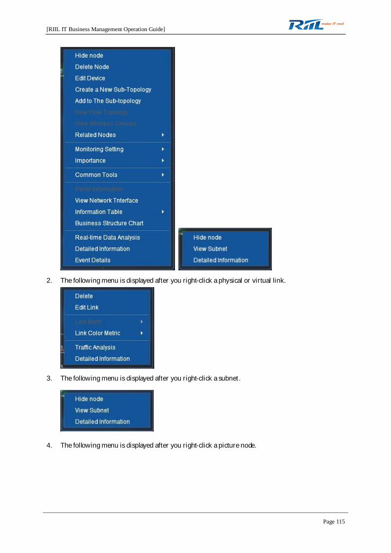
[RIIL IT Business Management Operation Guide]
Page 115
2. The following menu is displayed after you right-click a physical or virtual link.
3. The following menu is displayed after you right-click a subnet.
4. The following menu is displayed after you right-click a picture node.
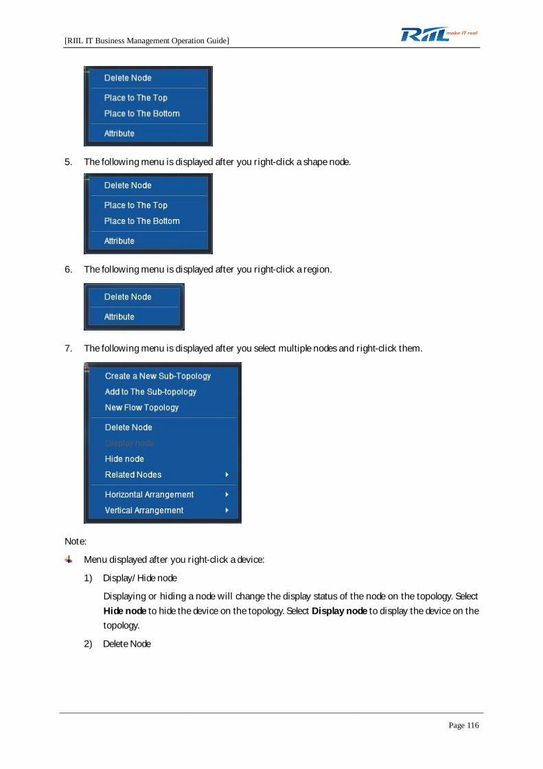
[RIIL IT Business Management Operation Guide]
Page 116
5. The following menu is displayed after you right-click a shape node.
6. The following menu is displayed after you right-click a region.
7. The following menu is displayed after you select multiple nodes and right-click them.
Note:
Menu displayed after you right-click a device:
1) Display/Hide node
Displaying or hiding a node will change the display status of the node on the topology. SelectHide node to hide the device on the topology. Select Display node to display the device on thetopology.
2) Delete Node

[RIIL IT Business Management Operation Guide]
Page 117
Select Delete Node. The following prompt box is displayed.
Click Ok. The node is deleted and the topology is automatically saved.
3) Edit Device
Select Edit Device. The Edit Device page is displayed, where you can set Displayed Name,IP Address, Device Type, and SNMP Version. The settings take effect immediately and aresaved automatically.
4) Create a New Sub-Topology
Sub-topologies can be added to layer 2 network topology, layer 3 network topology, and level1 sub-topologies of layer 2 and 3 network topologies.
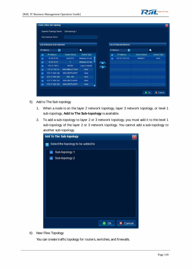
[RIIL IT Business Management Operation Guide]
Page 118
5) Add to The Sub-topology
1. When a node is on the layer 2 network topology, layer 3 network topology, or level 1sub-topology, Add to The Sub-topology is available.
2. To add a sub-topology to layer 2 or 3 network topology, you must add it to the level 1sub-topology of the layer 2 or 3 network topology. You cannot add a sub-topology toanother sub-topology.
6) New Flow Topology
You can create traffic topology for routers, switches, and firewalls.
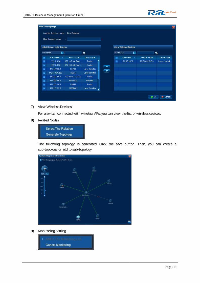
[RIIL IT Business Management Operation Guide]
Page 119
7) View Wireless Devices
For a switch connected with wireless APs, you can view the list of wireless devices.
8) Related Nodes
The following topology is generated. Click the save button. Then, you can create asub-topology or add to sub-topology.
9) Monitoring Setting
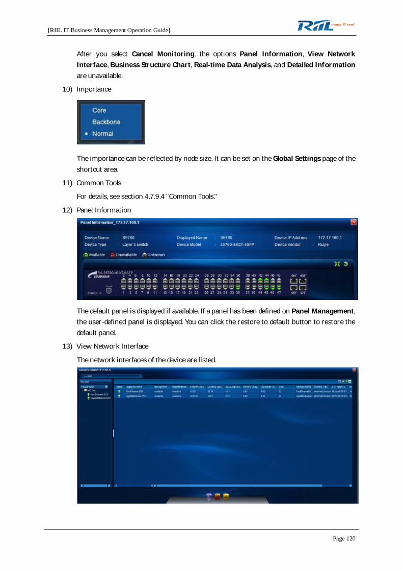
[RIIL IT Business Management Operation Guide]
Page 120
After you select Cancel Monitoring, the options Panel Information, View NetworkInterface, Business Structure Chart, Real-time Data Analysis, and Detailed Informationare unavailable.
10) Importance
The importance can be reflected by node size. It can be set on the Global Settings page of theshortcut area.
11) Common Tools
For details, see section 4.7.9.4 "Common Tools."
12) Panel Information
The default panel is displayed if available. If a panel has been defined on Panel Management,the user-defined panel is displayed. You can click the restore to default button to restore thedefault panel.
13) View Network Interface
The network interfaces of the device are listed.

[RIIL IT Business Management Operation Guide]
Page 121
14) Information Table has such submenu options as Interface Table, Address Table, RoutingTable, ARP Table, and VLAN Table.
15) Business Structure Chart
If the user who has permission to manage a resource selects Business Structure Chart, thebusiness structure chart page for the resource is displayed.
16) Real-time Data Analysis
If the user has permission to manage a resource, and the resource is under monitoring andavailable, the Real-time Data Analysis page for the resource is displayed when the userselects Real-time Data Analysis.
17) Detailed Information
If the user has permission to manage a resource and the resource is under monitoring, theDetailed Information page for the resource is displayed when the user selects DetailedInformation.

[RIIL IT Business Management Operation Guide]
Page 122
18) Event Details
The events of the current device are displayed.
Menu displayed after you right-click a link
1) Delete
1. If only one link is displayed, the Delete Link page is as follows.
2. If multiple links are displayed, a prompt box is displayed, prompting you to confirm thedeletion.

[RIIL IT Business Management Operation Guide]
Page 123
2) Edit Link
Editing a link will update the link information in all topologies. The modifications take effectimmediately and are saved automatically. The editing rules are as follows:
1. When only one link is displayed, the Edit Link page is as follows.
2. When multiple links are displayed, the Edit Link page is as follows.
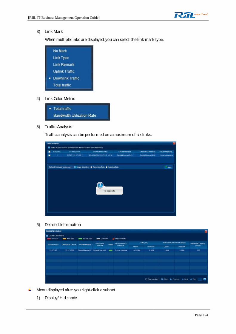
[RIIL IT Business Management Operation Guide]
Page 124
3) Link Mark
When multiple links are displayed, you can select the link mark type.
4) Link Color Metric
5) Traffic Analysis
Traffic analysis can be performed on a maximum of six links.
6) Detailed Information
Menu displayed after you right-click a subnet
1) Display/Hide node

[RIIL IT Business Management Operation Guide]
Page 125
Displaying or hiding a node will change the display status of the node on a specific topologicaldiagram. Select Hide node to hide the device on the topology. Select Display node to displaythe device on the topology.
2) View Subnet
3) Detailed Information
Click to view the information of the device directly connected to the selected device.
Menu displayed after you right-click a picture node
1) Delete Node
2) Place to The Top
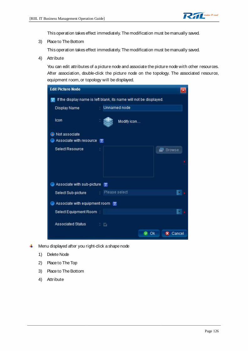
[RIIL IT Business Management Operation Guide]
Page 126
This operation takes effect immediately. The modification must be manually saved.
3) Place to The Bottom
This operation takes effect immediately. The modification must be manually saved.
4) Attribute
You can edit attributes of a picture node and associate the picture node with other resources.After association, double-click the picture node on the topology. The associated resource,equipment room, or topology will be displayed.
Menu displayed after you right-click a shape node
1) Delete Node
2) Place to The Top
3) Place to The Bottom
4) Attribute
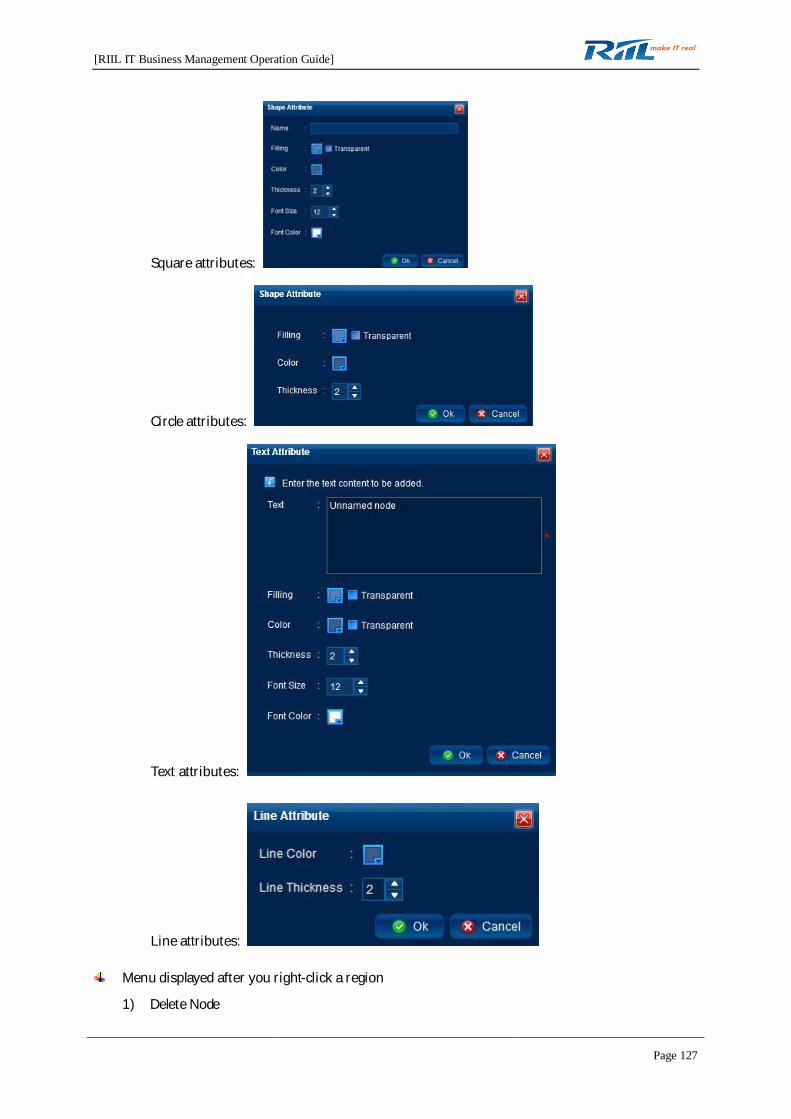
[RIIL IT Business Management Operation Guide]
Page 127
Square attributes:
Circle attributes:
Text attributes:
Line attributes:
Menu displayed after you right-click a region
1) Delete Node
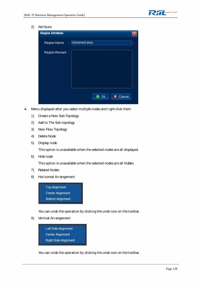
[RIIL IT Business Management Operation Guide]
Page 128
2) Attribute
Menu displayed after you select multiple nodes and right-click them
1) Create a New Sub-Topology
2) Add to The Sub-topology
3) New Flow Topology
4) Delete Node
5) Display node
This option is unavailable when the selected nodes are all displayed.
6) Hide node
This option is unavailable when the selected nodes are all hidden.
7) Related Nodes
8) Horizontal Arrangement
You can undo the operation by clicking the undo icon on the toolbar.
9) Vertical Arrangement
You can undo the operation by clicking the undo icon on the toolbar.

[RIIL IT Business Management Operation Guide]
Page 129
4.7.8.2 Right-Clicking in Blank Area
1. Layer 2 network topology
1) Set to The Default Page: used to set the default page displayed when a user accesses thenetwork topology tab.
2) Export: used to export topology information and generates image files.
3) Reset Layout: The menu options are the same as those of layout types.
4) Add Device
You can directly add a device or add a device from the resource pool.
Adding a new device:
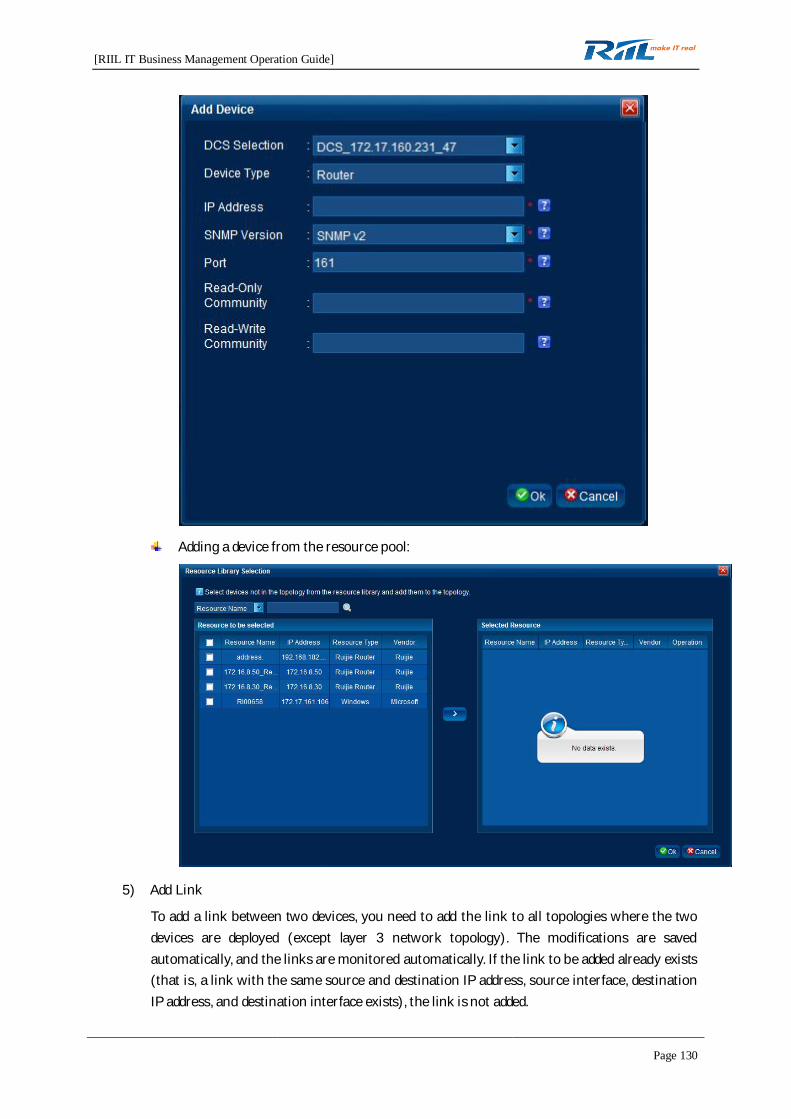
[RIIL IT Business Management Operation Guide]
Page 130
Adding a device from the resource pool:
5) Add Link
To add a link between two devices, you need to add the link to all topologies where the twodevices are deployed (except layer 3 network topology). The modifications are savedautomatically, and the links are monitored automatically. If the link to be added already exists(that is, a link with the same source and destination IP address, source interface, destinationIP address, and destination interface exists), the link is not added.

[RIIL IT Business Management Operation Guide]
Page 131
6) Hide resource or link prompt (or Display resource or link prompt)
You can hide or display prompts of resources or links on the current topology. This operationtakes effect immediately. The modification must be saved manually.
If Hide resource or link prompt is selected, the link or resource information is notdisplayed when you move the cursor upon a link or resource.
If Display resource or link prompt is selected, the link or resource information isdisplayed when you move the cursor upon a link or resource.
7) Display Hidden Nodes (or Does not Display Hidden Nodes)
You can select whether to display the hidden nodes on the current topology. This operationtakes effect immediately. The modification must be saved manually.
(Note: The hidden state of the resources is not changed.)
If Display Hidden Nodes is selected, the hidden nodes are displayed on the topology.
If Does not Display Hidden Nodes is selected, the hidden nodes are not displayed on thetopology.
8) View the List of Hidden Resources
You can display the hidden resources on the current topology and change the hidden state ofthe resources.
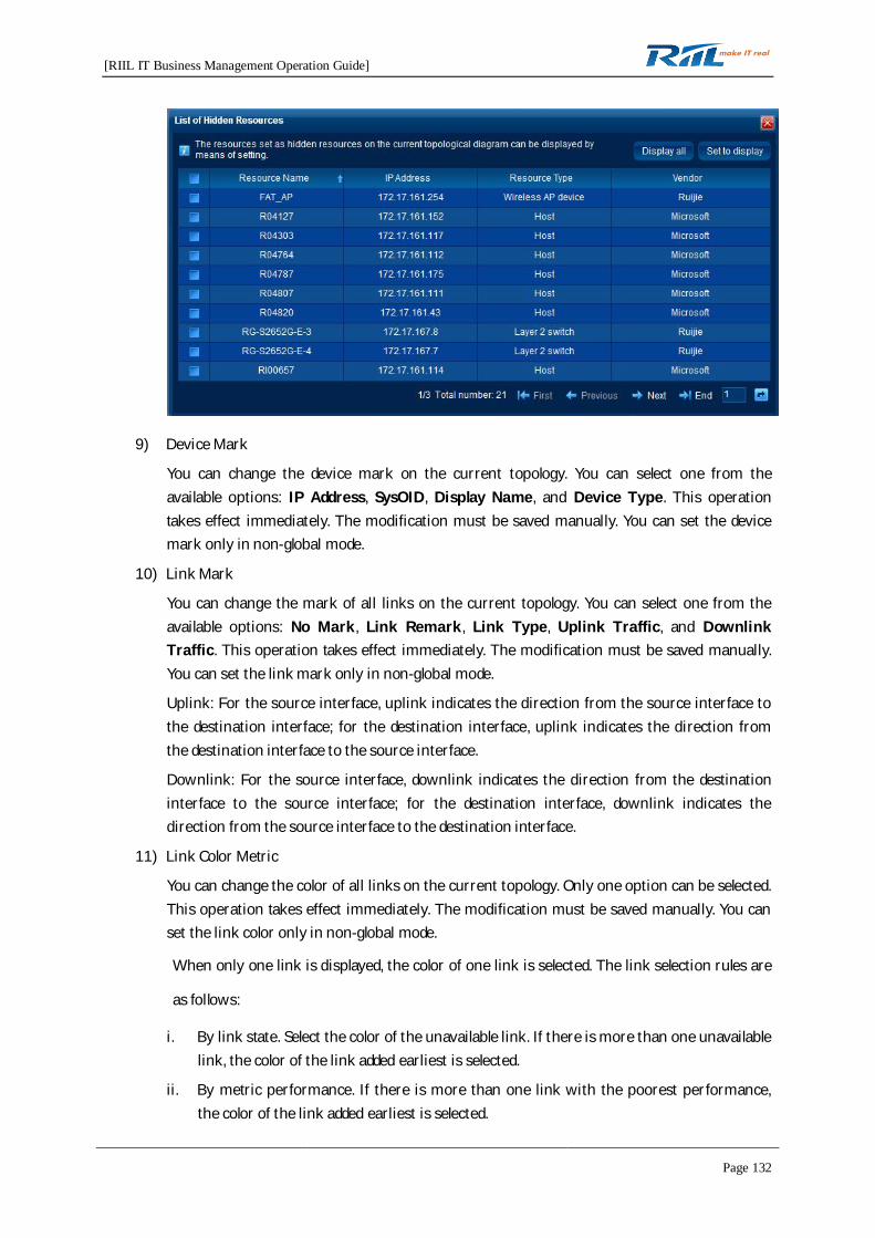
[RIIL IT Business Management Operation Guide]
Page 132
9) Device Mark
You can change the device mark on the current topology. You can select one from theavailable options: IP Address, SysOID, Display Name, and Device Type. This operationtakes effect immediately. The modification must be saved manually. You can set the devicemark only in non-global mode.
10) Link Mark
You can change the mark of all links on the current topology. You can select one from theavailable options: No Mark, Link Remark, Link Type, Uplink Traffic, and DownlinkTraffic. This operation takes effect immediately. The modification must be saved manually.You can set the link mark only in non-global mode.
Uplink: For the source interface, uplink indicates the direction from the source interface tothe destination interface; for the destination interface, uplink indicates the direction fromthe destination interface to the source interface.
Downlink: For the source interface, downlink indicates the direction from the destinationinterface to the source interface; for the destination interface, downlink indicates thedirection from the source interface to the destination interface.
11) Link Color Metric
You can change the color of all links on the current topology. Only one option can be selected.This operation takes effect immediately. The modification must be saved manually. You canset the link color only in non-global mode.
When only one link is displayed, the color of one link is selected. The link selection rules are
as follows:
i. By link state. Select the color of the unavailable link. If there is more than one unavailablelink, the color of the link added earliest is selected.
ii. By metric performance. If there is more than one link with the poorest performance,the color of the link added earliest is selected.

[RIIL IT Business Management Operation Guide]
Page 133
12) Display in single-/multi-link mode
You can change the display mode of links on the current topology. This operation takes effectimmediately. The modification must be saved manually. This option cannot be selected if itconflicts with the global settings.
If Display in Single-link mode is selected, only one link is displayed on the topology.
If Display in Multi-link mode is selected, multiple links are displayed on the topology.
13) Current Devices
All devices on the current topology are displayed, including hidden devices. You can clickto view resource details of a device.
14) Current Links
All links on the current topology are displayed. Click to edit information of a link.

[RIIL IT Business Management Operation Guide]
Page 134
15) Display Traffic
After you select Display Traffic, the topology switches to multi-link mode and the total trafficof all links is displayed. You can display the traffic only in non-global mode.
16) Node Setting
You can set the font size (the setting applies to Device Mark, Link Mark, Picture NodeName, Region Name, and Virtual Device Name) and font color (the setting applies toDevice Mark, Picture Node Name, and Virtual Device Name). You can perform nodesetting only in non-global mode.
2. Layer 3 network topology
1) Set to The Default Page: used to set the default page displayed when a user accesses thenetwork topology tab.
2) Export: used to export topology information and generates image files.
3) Reset Layout: The menu options are the same as those of layout types.

[RIIL IT Business Management Operation Guide]
Page 135
4) Hide resource or link prompt (or Display resource or link prompt)
You can hide or display prompts of resources or links on the current topology. This operationtakes effect immediately. The modification must be saved manually.
If Hide resource or link prompt is selected, the link or resource information is notdisplayed when you move the cursor upon a link or resource.
If Display resource or link prompt is selected, the link or resource information isdisplayed when you move the cursor upon a link or resource.
5) Display Hidden Nodes (or Does not Display Hidden Nodes)
You can select whether to display the hidden nodes on the current topology. This operationtakes effect immediately. The modification must be saved manually.
(Note: The hidden state of the resources is not changed.)
If Display Hidden Nodes is selected, the hidden nodes are displayed on the topology.
If Does not Display Hidden Nodes is selected, the hidden nodes are not displayed on thetopology.
6) View the List of Hidden Resources: used to display the hidden resources on the currenttopology.
7) Device Mark
You can change the device mark on the current topology. Only one option can be selected.This operation takes effect immediately. The modification must be manually saved. Thesetting cannot be saved if it conflicts with the global settings.
8) Current Devices: used to display all devices on the current topology, including hidden devices.
9) Node Setting
You can set the font size (the setting applies to Device Mark, Link Mark, Picture NodeName, Region Name, and Virtual Device Name) and font color (the setting applies toDevice Mark, Picture Node Name, and Virtual Device Name).
3. Sub-topology
1) Sub-topology diagram of layer 2 network topology
The shortcut menu does not have the Add Device option. Other menu options are the sameas those in the shortcut menu for layer 2 network topology.
2) Sub-topology diagram of layer 3 network topology
The sub-topology of the layer 3 network topology is the same as the layer 3 network topology.For the shortcut menu of the sub-topology, see the shortcut menu of the layer 3 networktopology.
4. User-defined topology
The shortcut menu for the user-defined topology does not have the Reset Layout option. Othermenu options are the same as those of the shortcut menu for the layer 2 network sub-topology.

[RIIL IT Business Management Operation Guide]
Page 136
4.7.9 Shortcut Button Area
4.7.9.1 Global Setting
Only the system administrator can set devices, links, and topologies globally.
When Display based on global settings is selected, relevant functions on the topology are restricted.
1. Device

[RIIL IT Business Management Operation Guide]
Page 137
2. Link
Metric Threshold Setting page
3. Topology

[RIIL IT Business Management Operation Guide]
Page 138
4.7.9.2 Topology Discovery
Only the system administrator can use the topology discovery function. The discovery algorithm canbe selected and SNMP can be set on the Discovery Configuration tab page.
4.7.9.3 Permission Management
Users other than the system administrator can access the Permission Management page only for thetopology they have permission to operate.
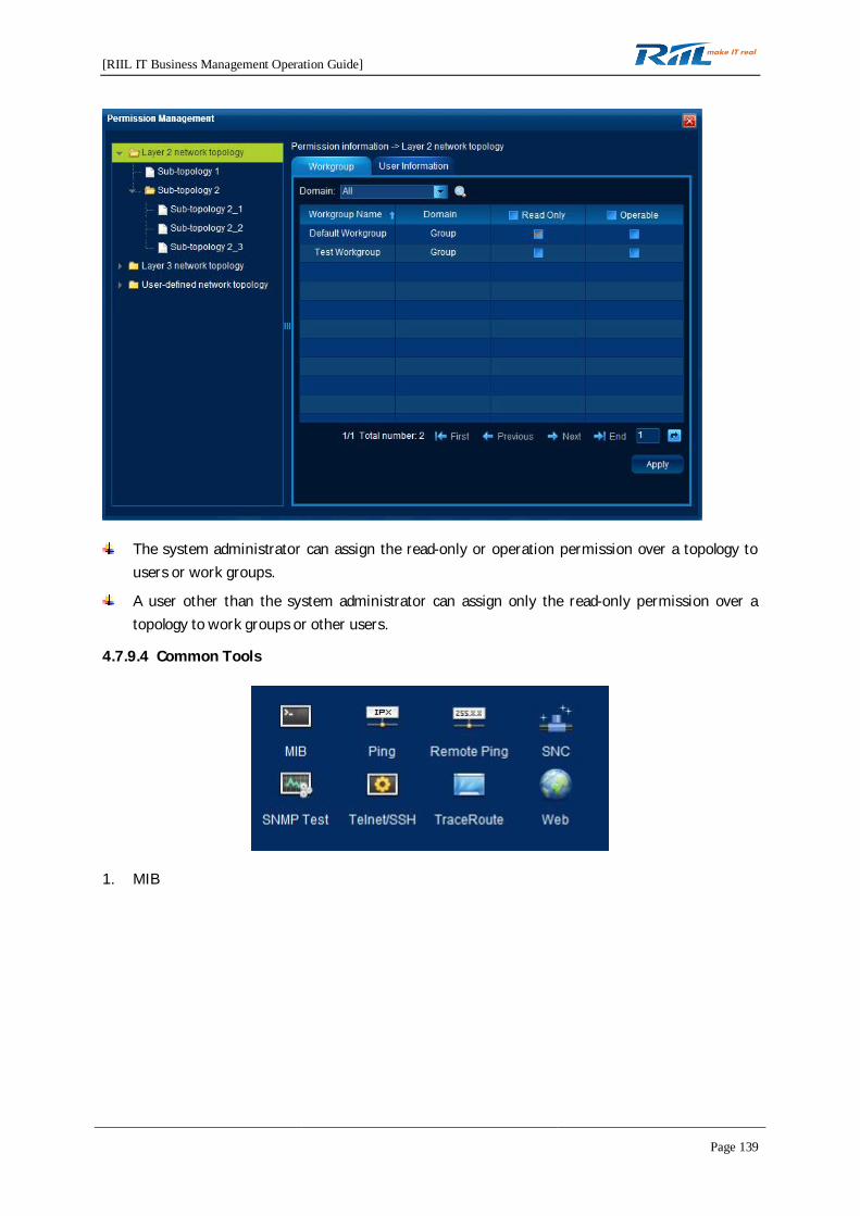
[RIIL IT Business Management Operation Guide]
Page 139
The system administrator can assign the read-only or operation permission over a topology tousers or work groups.
A user other than the system administrator can assign only the read-only permission over atopology to work groups or other users.
4.7.9.4 Common Tools
1. MIB
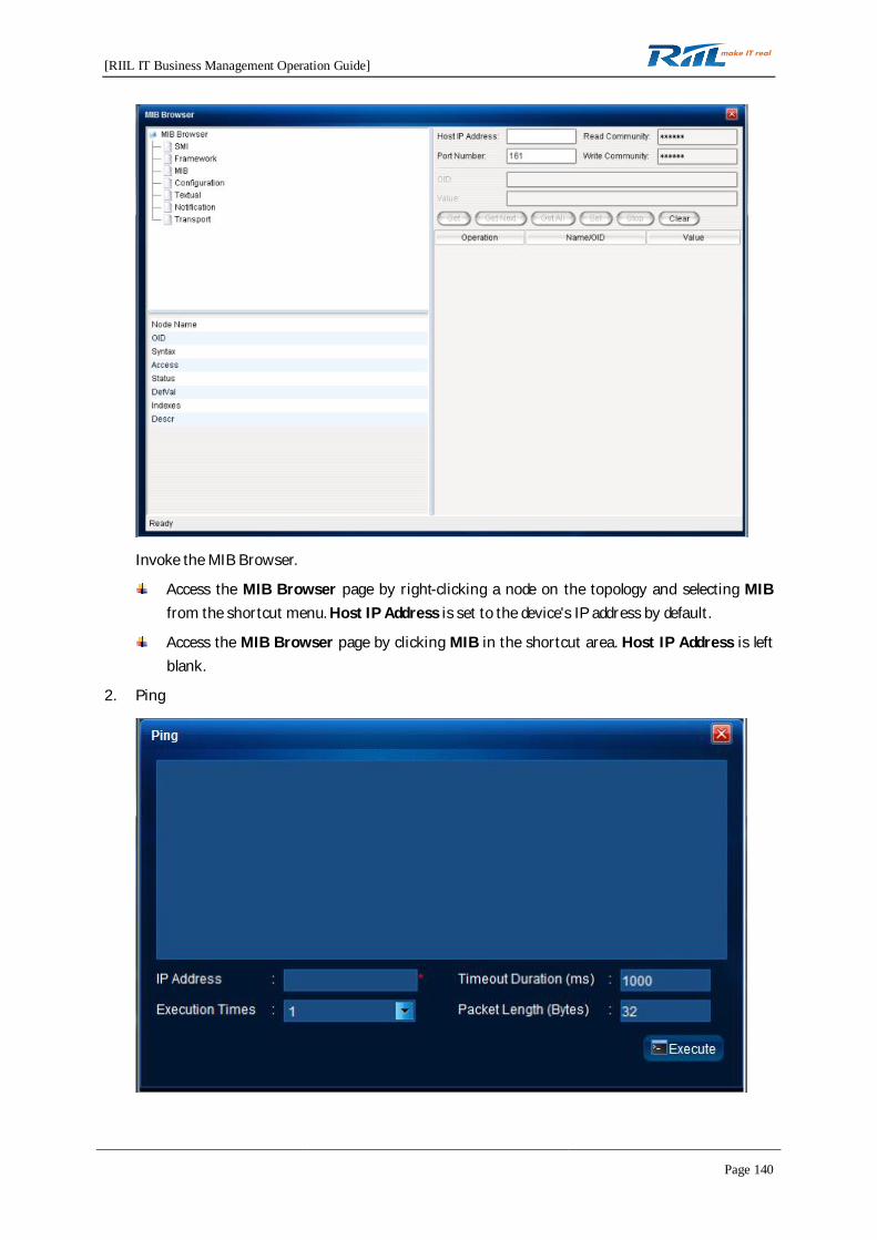
[RIIL IT Business Management Operation Guide]
Page 140
Invoke the MIB Browser.
Access the MIB Browser page by right-clicking a node on the topology and selecting MIBfrom the shortcut menu. Host IP Address is set to the device's IP address by default.
Access the MIB Browser page by clicking MIB in the shortcut area. Host IP Address is leftblank.
2. Ping
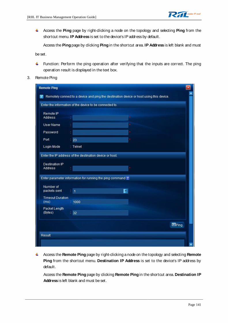
[RIIL IT Business Management Operation Guide]
Page 141
Access the Ping page by right-clicking a node on the topology and selecting Ping from theshortcut menu. IP Address is set to the device's IP address by default.
Access the Ping page by clicking Ping in the shortcut area. IP Address is left blank and must
be set.
Function: Perform the ping operation after verifying that the inputs are correct. The pingoperation result is displayed in the text box.
3. Remote Ping
Access the Remote Ping page by right-clicking a node on the topology and selecting RemotePing from the shortcut menu. Destination IP Address is set to the device's IP address bydefault.
Access the Remote Ping page by clicking Remote Ping in the shortcut area. Destination IPAddress is left blank and must be set.
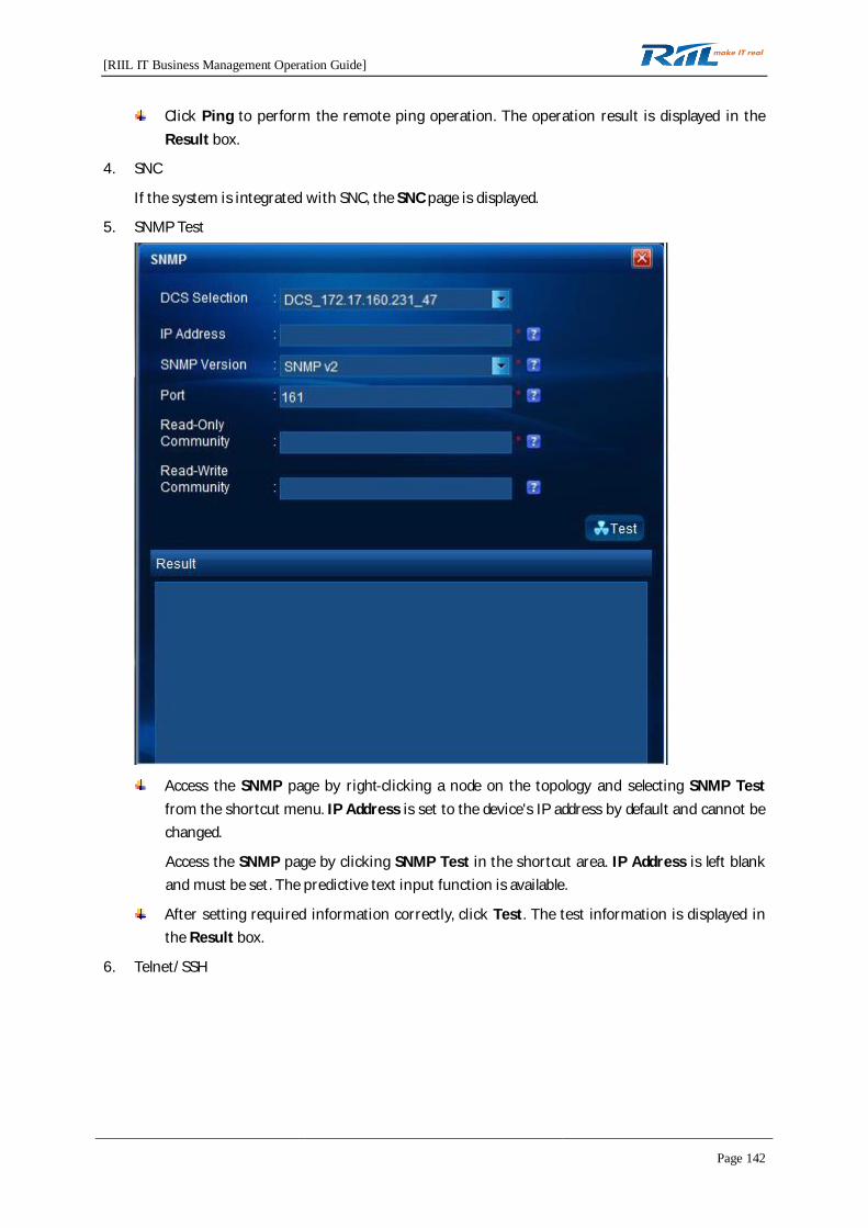
[RIIL IT Business Management Operation Guide]
Page 142
Click Ping to perform the remote ping operation. The operation result is displayed in theResult box.
4. SNC
If the system is integrated with SNC, the SNC page is displayed.
5. SNMP Test
Access the SNMP page by right-clicking a node on the topology and selecting SNMP Testfrom the shortcut menu. IP Address is set to the device's IP address by default and cannot bechanged.
Access the SNMP page by clicking SNMP Test in the shortcut area. IP Address is left blankand must be set. The predictive text input function is available.
After setting required information correctly, click Test. The test information is displayed inthe Result box.
6. Telnet/SSH
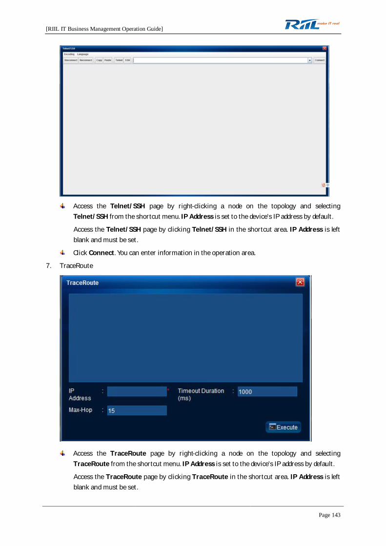
[RIIL IT Business Management Operation Guide]
Page 143
Access the Telnet/SSH page by right-clicking a node on the topology and selectingTelnet/SSH from the shortcut menu. IP Address is set to the device's IP address by default.
Access the Telnet/SSH page by clicking Telnet/SSH in the shortcut area. IP Address is leftblank and must be set.
Click Connect. You can enter information in the operation area.
7. TraceRoute
Access the TraceRoute page by right-clicking a node on the topology and selectingTraceRoute from the shortcut menu. IP Address is set to the device's IP address by default.
Access the TraceRoute page by clicking TraceRoute in the shortcut area. IP Address is leftblank and must be set.
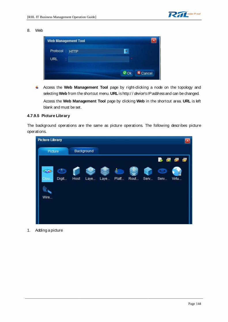
[RIIL IT Business Management Operation Guide]
Page 144
8. Web
Access the Web Management Tool page by right-clicking a node on the topology andselecting Web from the shortcut menu. URL is http://device's IP address and can be changed.
Access the Web Management Tool page by clicking Web in the shortcut area. URL is leftblank and must be set.
4.7.9.5 Picture Library
The background operations are the same as picture operations. The following describes pictureoperations.
1. Adding a picture
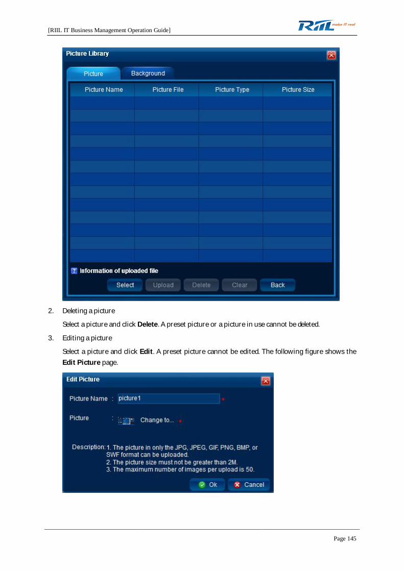
[RIIL IT Business Management Operation Guide]
Page 145
2. Deleting a picture
Select a picture and click Delete. A preset picture or a picture in use cannot be deleted.
3. Editing a picture
Select a picture and click Edit. A preset picture cannot be edited. The following figure shows theEdit Picture page.

[RIIL IT Business Management Operation Guide]
Page 146
4.7.9.6 Panel Management
1. Panel tree
The panel tree consists of device types and network device series. Device series are under thedevice type. The number of devices of the same device type is displayed next to a device type.
1) Import
2) Export
Export panel information. Only panel configurations are exported.
3) Device types can be added and exported.
(1) Create

[RIIL IT Business Management Operation Guide]
Page 147
Panel Name: The panel name must be specified. The panel names for devices of thesame series cannot be identical.
(2) Export: Export panel configurations.
2. Panel-related operations
1) System panel
2) Non-system panel
3. Panel Configuration
Displaying panel information
Panel information includes Panel Name, Device Type, Device Vendor, and Device Series.
Editing the panel
: used to preview the panel
: used to display the panel in full screen
: used to open the panel tool page
: used to automatically obtain an interface
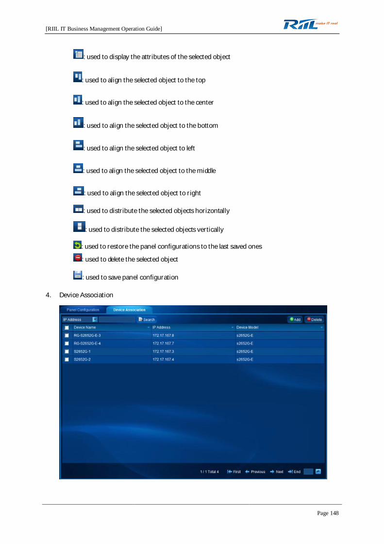
[RIIL IT Business Management Operation Guide]
Page 148
: used to display the attributes of the selected object
: used to align the selected object to the top
: used to align the selected object to the center
: used to align the selected object to the bottom
: used to align the selected object to left
: used to align the selected object to the middle
: used to align the selected object to right
: used to distribute the selected objects horizontally
: used to distribute the selected objects vertically
: used to restore the panel configurations to the last saved ones
: used to delete the selected object
: used to save panel configuration
4. Device Association
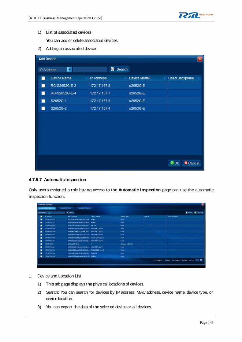
[RIIL IT Business Management Operation Guide]
Page 149
1) List of associated devices
You can add or delete associated devices.
2) Adding an associated device
4.7.9.7 Automatic Inspection
Only users assigned a role having access to the Automatic Inspection page can use the automaticinspection function.
1. Device and Location List
1) This tab page displays the physical locations of devices.
2) Search: You can search for devices by IP address, MAC address, device name, device type, ordevice location.
3) You can export the data of the selected device or all devices.
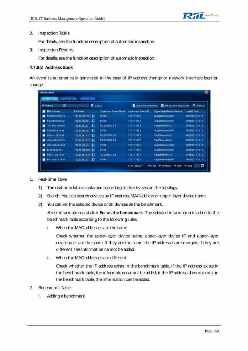
[RIIL IT Business Management Operation Guide]
Page 150
2. Inspection Tasks
For details, see the function description of automatic inspection.
3. Inspection Reports
For details, see the function description of automatic inspection.
4.7.9.8 Address Book
An event is automatically generated in the case of IP address change or network interface locationchange.
1. Real-time Table
1) The real-time table is obtained according to the devices on the topology.
2) Search: You can search devices by IP address, MAC address or upper-layer device name.
3) You can set the selected device or all devices as the benchmark.
Select information and click Set as the benchmark. The selected information is added to thebenchmark table according to the following rules:
i. When the MAC addresses are the same
Check whether the upper-layer device name, upper-layer device IP, and upper-layerdevice port are the same. If they are the same, the IP addresses are merged; if they aredifferent, the information cannot be added.
ii. When the MAC addresses are different
Check whether the IP address exists in the benchmark table. If the IP address exists inthe benchmark table, the information cannot be added; if the IP address does not exist inthe benchmark table, the information can be added.
2. Benchmark Table
i. Adding a benchmark

[RIIL IT Business Management Operation Guide]
Page 151
ii. Deleting a benchmark
Select a benchmark and click Delete to delete the selected benchmark from the benchmarktable. If the deleted benchmark is from the historical table, the historical information can beoperable.
iii. Importing benchmarks
The rules for importing information to the benchmark table are as follows:
When the MAC addresses are the same
Check whether the upper-layer device name, upper-layer device IP, and upper-layerdevice port are the same. If they are the same, the IP addresses are merged; if they aredifferent, the information cannot be added.
When the MAC addresses are different
Check whether the IP addresses are the same. If the IP addresses are the same, theinformation cannot be added; if the IP addresses are different, the information can beadded.
iv. Exporting benchmarks
You can export the information from the benchmark table.
3. Historical Table
1) If the MAC address in the real-time table exists in the benchmark table, check whether thecorresponding IP address and upper-layer device name are changed. If so, the information isdisplayed in the historical table.
2) Search: You can search for information by MAC address or change time. The change time isthe latest 24 hours by default.
3) Buttons: Set as the benchmark, Delete
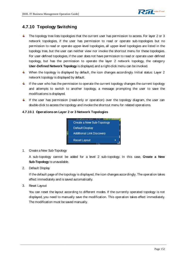
[RIIL IT Business Management Operation Guide]
Page 152
4.7.10 Topology Switching
The topology tree lists topologies that the current user has permission to access. For layer 2 or 3network topologies, if the user has permission to read or operate sub-topologies but nopermission to read or operate upper-level topologies, all upper-level topologies are listed in thetopology tree, but the user can neither view nor invoke the shortcut menu for these topologies.For user-defined topologies, if the user does not have permission to read or operate user-definedtopology, but has the permission to operate the layer 2 network topology, the categoryUser-Defined Network Topology is displayed, and a right-click menu can be invoked.
When the topology is displayed by default, the icon changes accordingly. Initial status: Layer 2network topology is displayed by default.
If the user who has the permission to operate the current topology changes the current topologyand attempts to switch to another topology, a message prompting the user to save themodifications is displayed.
If the user has permission (read-only or operation) over the topology diagram, the user candouble-click to access the topology and invoke the shortcut menu for related operations.
4.7.10.1 Operations on Layer 2 or 3 Network Topologies
1. Create a New Sub-Topology
A sub-topology cannot be added for a level 2 sub-topology. In this case, Create a NewSub-Topology is unavailable.
2. Default Display
If the default page of the topology is displayed, the icon changes accordingly. The operation takeseffect immediately and is saved automatically.
3. Reset Layout
You can reset the layout according to different modes. If the currently operated topology is notdisplayed, you need to manually save the modification. This operation takes effect immediately.The modification must be saved manually.

[RIIL IT Business Management Operation Guide]
Page 153
4.7.10.2 Operations on Sub-topologies
1. Create a New Sub-Topology
A sub-topology cannot be added for a level 2 sub-topology. In this case, Create a NewSub-Topology is unavailable.
2. Default Display
The function is the same as that for layer 2 network topology. For details, see the default displayfunction of layer 2 network topology.
3. Delete
The system performs the following judgments before deletion:
1) If the topology is the default display topology, makes the Delete option unavailable.
2) Checks whether any sub-topology exists under the topology. If yes, makes the Delete optionunavailable;
3) if no, displays the following message.
4) If the deleted topology is the currently opened topology, displays the default topology afterthe current topology is deleted.
4. Edit
Select Edit. The Edit Sub-topology page is displayed.

[RIIL IT Business Management Operation Guide]
Page 154
5. Reset Layout: The function is the same as that for layer 2 network topology. For details, see thereset layout function of layer 2 network topology.
4.7.10.3 Self-defined Topology
1. Self-defined topology
When the user has permission to operate the self-defined topology,
is available. The user is automatically assigned
permission to operate the self-defined topology.
2. Operations on the self-defined topology

[RIIL IT Business Management Operation Guide]
Page 155
1) Default Display
If the currently operated topology is not opened, Default Display is unavailable. If thedefault page of the topology is displayed, the icon changes accordingly. The operation takeseffect immediately and is saved automatically.
2) Delete
For details, see "Delete" in 4.7.10.2 "Operations on Sub-topologies."
3) Edit
Select Edit. The Edit the Self-defined Topology page is displayed.
4.7.11 Resource Panel
Only users who have permission to operate the current topology can use the resource panel to addresources. Resources include devices/links, pictures, regions, backgrounds, and shapes. Topologicaldiagrams of different types support different types of resources.
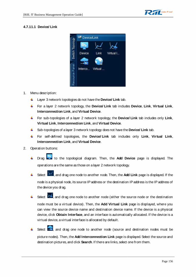
[RIIL IT Business Management Operation Guide]
Page 156
4.7.11.1 Device/Link
1. Menu description:
Layer 3 network topologies do not have the Device/Link tab.
For a layer 2 network topology, the Device/Link tab includes Device, Link, Virtual Link,Interconnection Link, and Virtual Device.
For sub-topologies of a layer 2 network topology, the Device/Link tab includes only Link,Virtual Link, Interconnection Link, and Virtual Device.
Sub-topologies of a layer 3 network topology does not have the Device/Link tab.
For self-defined topologies, the Device/Link tab includes only Link, Virtual Link,Interconnection Link, and Virtual Device.
2. Operation buttons:
Drag to the topological diagram. Then, the Add Device page is displayed. The
operations are the same as those on a layer 2 network topology.
Select , and drag one node to another node. Then, the Add Link page is displayed. If the
node is a physical node, its source IP address or the destination IP address is the IP address ofthe device you drag.
Select , and drag one node to another node (either the source node or the destination
node must be a virtual device). Then, the Add Virtual Link page is displayed, where youcan view the source device name and destination device name. If the device is a physicaldevice, click Obtain Interface, and an interface is automatically allocated. If the device is avirtual device, a virtual interface is allocated by default.
Select , and drag one node to another node (source and destination nodes must be
picture nodes). Then, the Add Interconnection Link page is displayed. Select the source anddestination pictures, and click Search. If there are links, select one from them.
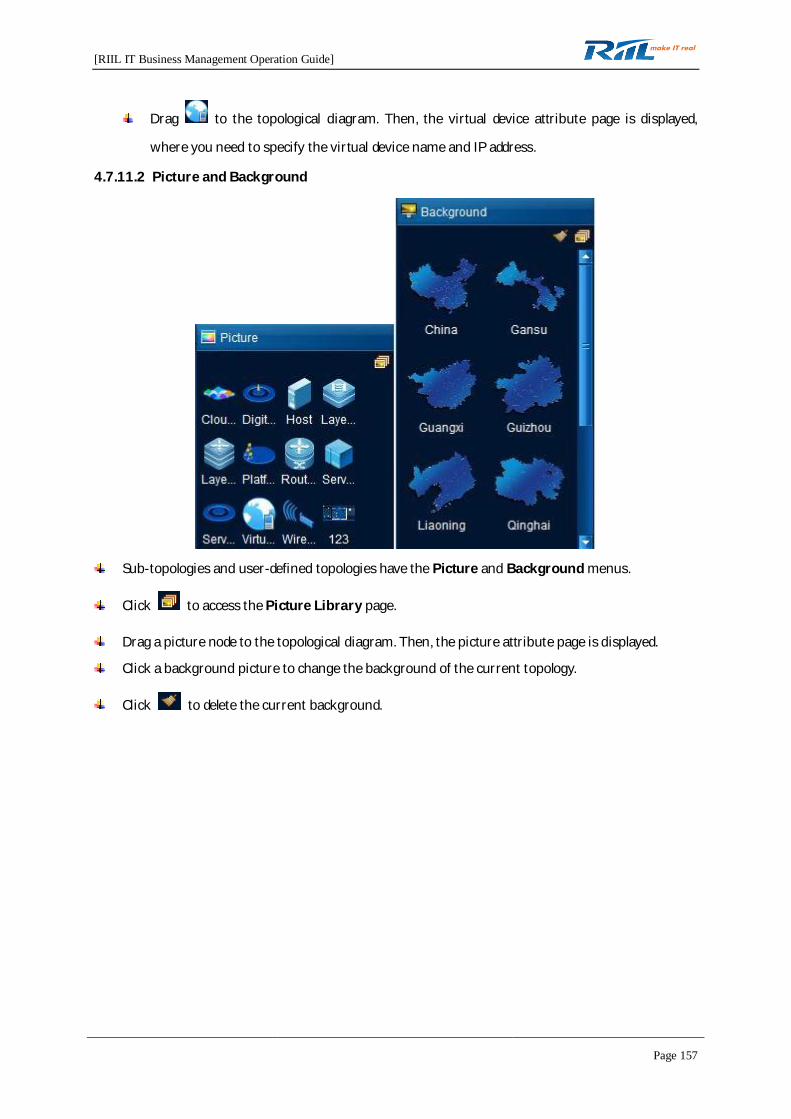
[RIIL IT Business Management Operation Guide]
Page 157
Drag to the topological diagram. Then, the virtual device attribute page is displayed,
where you need to specify the virtual device name and IP address.
4.7.11.2 Picture and Background
Sub-topologies and user-defined topologies have the Picture and Background menus.
Click to access the Picture Library page.
Drag a picture node to the topological diagram. Then, the picture attribute page is displayed.
Click a background picture to change the background of the current topology.
Click to delete the current background.
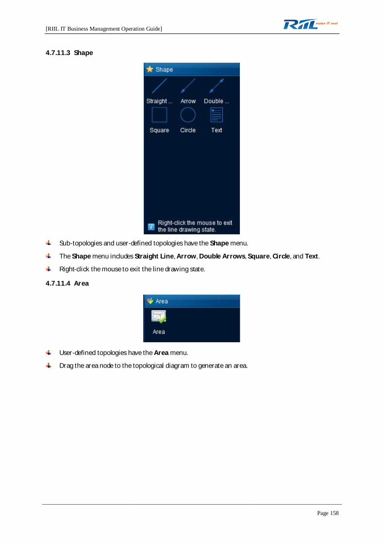
[RIIL IT Business Management Operation Guide]
Page 158
4.7.11.3 Shape
Sub-topologies and user-defined topologies have the Shape menu.
The Shape menu includes Straight Line, Arrow, Double Arrows, Square, Circle, and Text.
Right-click the mouse to exit the line drawing state.
4.7.11.4 Area
User-defined topologies have the Area menu.
Drag the area node to the topological diagram to generate an area.

[RIIL IT Business Management Operation Guide]
Page 159
4.8 Traffic Analysis
4.8.1 Flow Topology
Only users having the traffic analysis permission can access the Flow Topology page. The followingbriefly describes how to draw a flow topology.
4.8.1.1 Drawing a Flow Topology
On the Switch Topology panel, right-click a flow topology node and select New Flow Topology fromthe shortcut menu. In the displayed New Flow Topology dialog box, select devices. Then, a topologicaldiagram for traffic between the devices is displayed. By default, traffic data is presented by Velocity.
4.8.1.2 Shortcut Button Area
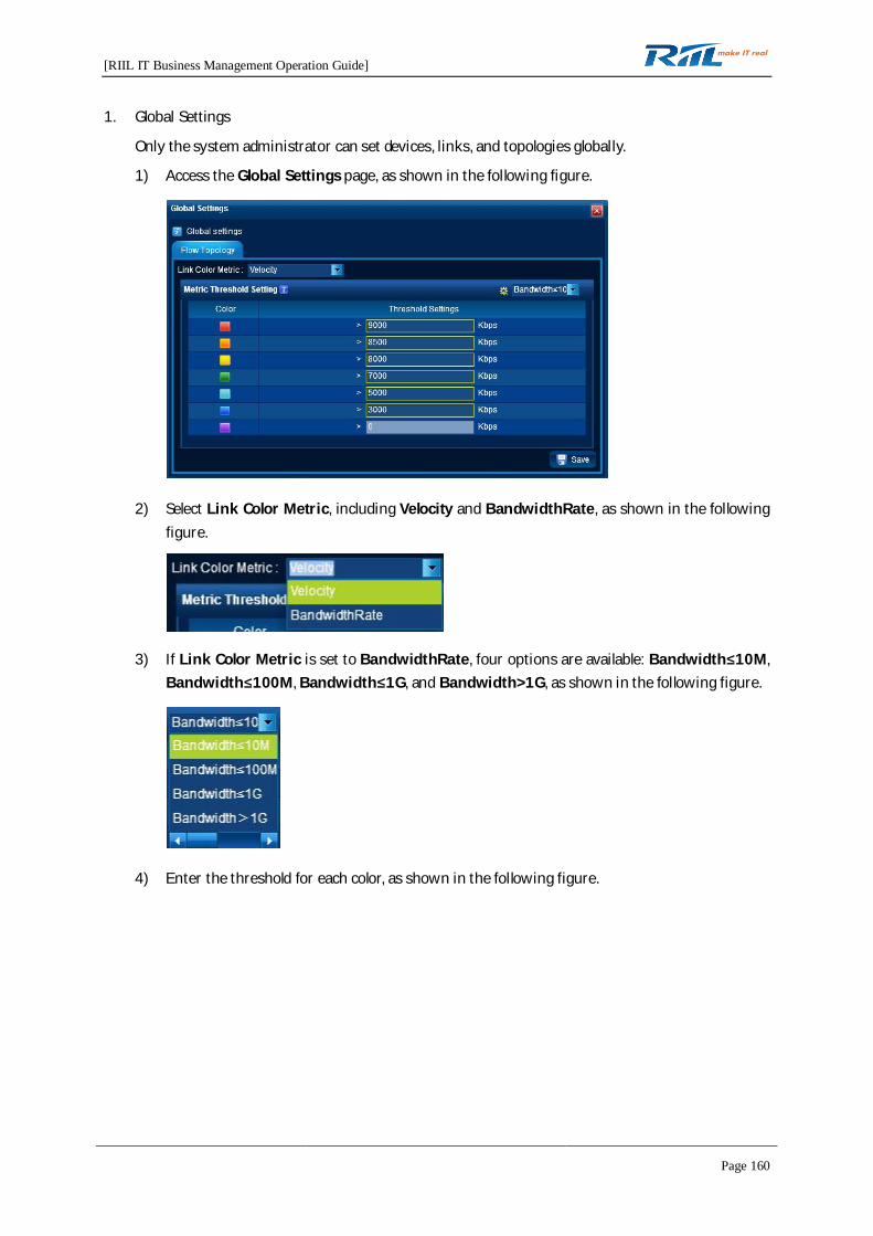
[RIIL IT Business Management Operation Guide]
Page 160
1. Global Settings
Only the system administrator can set devices, links, and topologies globally.
1) Access the Global Settings page, as shown in the following figure.
2) Select Link Color Metric, including Velocity and BandwidthRate, as shown in the followingfigure.
3) If Link Color Metric is set to BandwidthRate, four options are available: Bandwidth 10M,Bandwidth 100M, Bandwidth 1G, and Bandwidth>1G, as shown in the following figure.
4) Enter the threshold for each color, as shown in the following figure.

[RIIL IT Business Management Operation Guide]
Page 161
5) Click to save the global settings. In the topological diagram, each link is
displayed in the corresponding color according to the velocity threshold setting.
6) Click to restore the bandwidth threshold settings to the default settings.
2. Picture Library
1) Click and add a self-defined picture, as shown in the following figure.
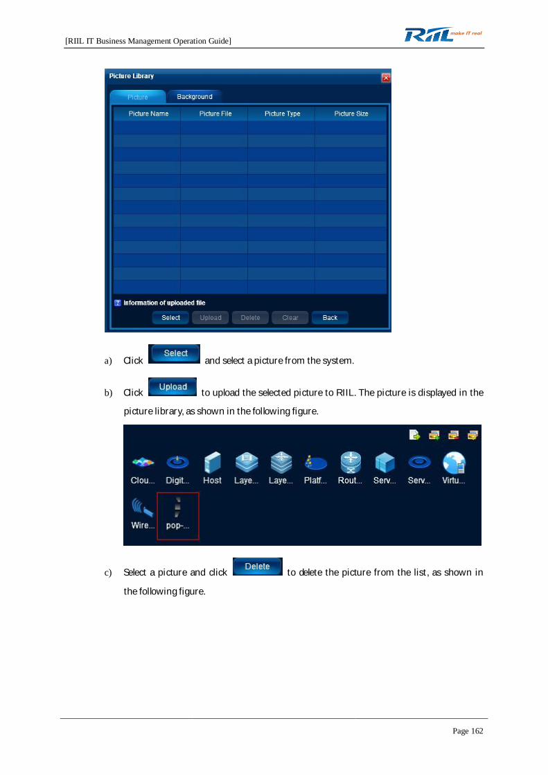
[RIIL IT Business Management Operation Guide]
Page 162
a) Click and select a picture from the system.
b) Click to upload the selected picture to RIIL. The picture is displayed in the
picture library, as shown in the following figure.
c) Select a picture and click to delete the picture from the list, as shown in
the following figure.
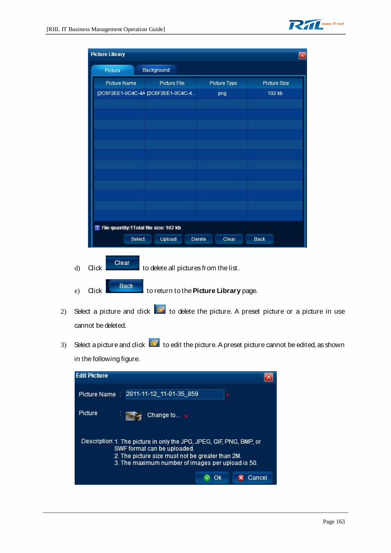
[RIIL IT Business Management Operation Guide]
Page 163
d) Click to delete all pictures from the list.
e) Click to return to the Picture Library page.
2) Select a picture and click to delete the picture. A preset picture or a picture in use
cannot be deleted.
3) Select a picture and click to edit the picture. A preset picture cannot be edited, as shown
in the following figure.
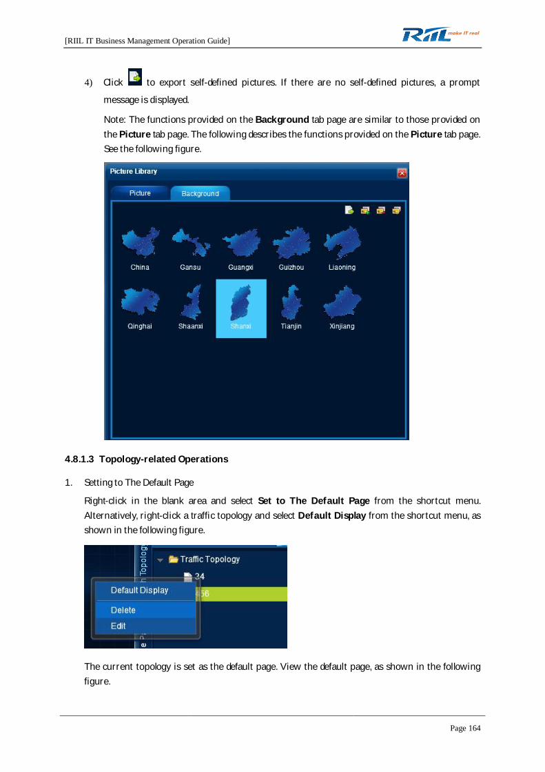
[RIIL IT Business Management Operation Guide]
Page 164
4) Click to export self-defined pictures. If there are no self-defined pictures, a prompt
message is displayed.
Note: The functions provided on the Background tab page are similar to those provided onthe Picture tab page. The following describes the functions provided on the Picture tab page.See the following figure.
4.8.1.3 Topology-related Operations
1. Setting to The Default Page
Right-click in the blank area and select Set to The Default Page from the shortcut menu.Alternatively, right-click a traffic topology and select Default Display from the shortcut menu, asshown in the following figure.
The current topology is set as the default page. View the default page, as shown in the followingfigure.

[RIIL IT Business Management Operation Guide]
Page 165
2. Resource Panel
1) Adding a device
Right-click the blank area and select Add Device from the shortcut menu. Alternatively, click
the Resource Panel tab on the drawing panel, and drag from the Device/Link area to
the topology, as shown in the following figure.
The Add Device dialog box is displayed, as shown in the following figure. Enter requiredinformation and save it.
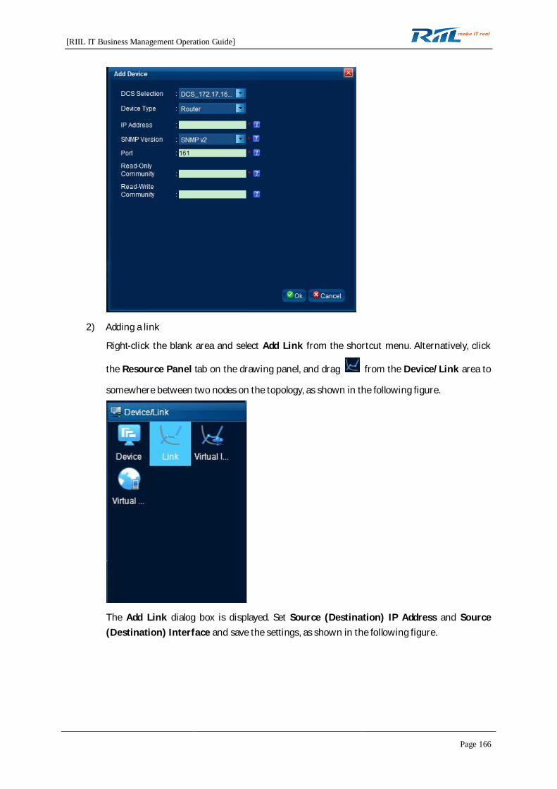
[RIIL IT Business Management Operation Guide]
Page 166
2) Adding a link
Right-click the blank area and select Add Link from the shortcut menu. Alternatively, click
the Resource Panel tab on the drawing panel, and drag from the Device/Link area to
somewhere between two nodes on the topology, as shown in the following figure.
The Add Link dialog box is displayed. Set Source (Destination) IP Address and Source(Destination) Interface and save the settings, as shown in the following figure.

[RIIL IT Business Management Operation Guide]
Page 167
3) Adding a virtual device
Click the Resource Panel tab on the drawing panel, and drag from the Device/Link
area to the topology, as shown in the following figure.
Set Virtual Device Name (mandatory) and IP Address and click Ok. The added virtualdevice is displayed on the topology.
4) Adding a virtual link
Click the Resource Panel tab on the drawing panel, and drag from the Device/Link
area to somewhere between two nodes on the topology (a virtual link can be added onlybetween a virtual device and a physical device), as shown in the following figure.

[RIIL IT Business Management Operation Guide]
Page 168
5) Adding a picture
On the drawing panel, click the Resource Panel tab, drag a picture from the Picture area tothe topology, and then save the modification, as shown in the following figure.
6) Adding a background
On the drawing panel, click the Resource Panel tab, drag a picture from the Backgroundarea to the topology, and then save the modification, as shown in the following figure.
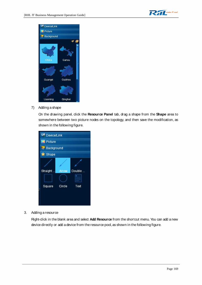
[RIIL IT Business Management Operation Guide]
Page 169
7) Adding a shape
On the drawing panel, click the Resource Panel tab, drag a shape from the Shape area tosomewhere between two picture nodes on the topology, and then save the modification, asshown in the following figure.
3. Adding a resource
Right-click in the blank area and select Add Resource from the shortcut menu. You can add a newdevice directly or add a device from the resource pool, as shown in the following figure.
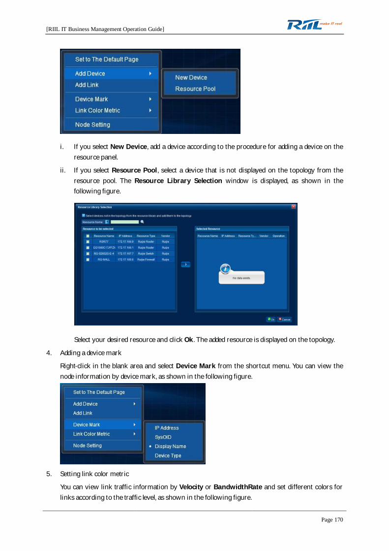
[RIIL IT Business Management Operation Guide]
Page 170
i. If you select New Device, add a device according to the procedure for adding a device on theresource panel.
ii. If you select Resource Pool, select a device that is not displayed on the topology from theresource pool. The Resource Library Selection window is displayed, as shown in thefollowing figure.
Select your desired resource and click Ok. The added resource is displayed on the topology.
4. Adding a device mark
Right-click in the blank area and select Device Mark from the shortcut menu. You can view thenode information by device mark, as shown in the following figure.
5. Setting link color metric
You can view link traffic information by Velocity or BandwidthRate and set different colors forlinks according to the traffic level, as shown in the following figure.

[RIIL IT Business Management Operation Guide]
Page 171
6. Performing node setting
Right-click in the blank area and select Node Setting from the shortcut menu. You can set nodetext display, as shown in the following figure.
7. Deleting a node
Right-click a node on the topology and select Delete Node from the shortcut menu to delete thenode and the associated link and shape, as shown in the following figure.
8. Link-related operations
Right-click a link on the topology. A shortcut menu is displayed, as shown in the following figure.
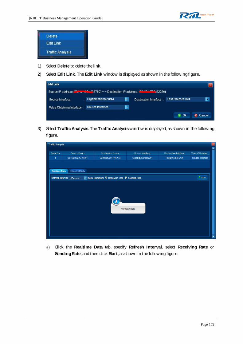
[RIIL IT Business Management Operation Guide]
Page 172
1) Select Delete to delete the link.
2) Select Edit Link. The Edit Link window is displayed, as shown in the following figure.
3) Select Traffic Analysis. The Traffic Analysis window is displayed, as shown in the followingfigure.
a) Click the Realtime Data tab, specify Refresh Interval, select Receiving Rate orSending Rate, and then click Start, as shown in the following figure.
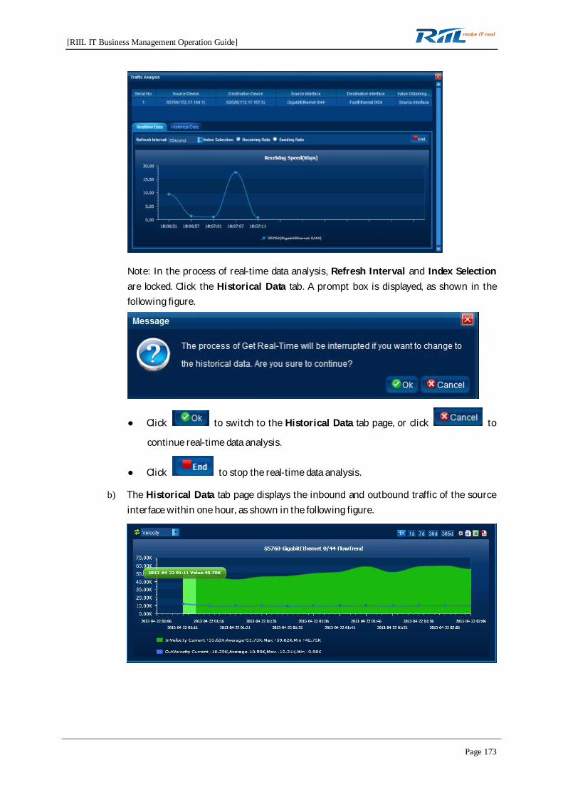
[RIIL IT Business Management Operation Guide]
Page 173
Note: In the process of real-time data analysis, Refresh Interval and Index Selectionare locked. Click the Historical Data tab. A prompt box is displayed, as shown in thefollowing figure.
Click to switch to the Historical Data tab page, or click to
continue real-time data analysis.
Click to stop the real-time data analysis.
b) The Historical Data tab page displays the inbound and outbound traffic of the sourceinterface within one hour, as shown in the following figure.

[RIIL IT Business Management Operation Guide]
Page 174
i. Select the metric , and the trend graph is refreshed according
to the selected metric.
ii. Click to manually refresh the trend graph.
iii. Click to display the data of the latest one hour, one day,
one week, one month, and one year.
iv. Specify the time period, as shown in the following figure. The data of the specified
period is displayed.
v. Click to export data to a Word file, an Excel file, and a PDF file.
4.8.1.4 Viewing Topologies
You can click icons in the toolbar to view traffic topology as required.
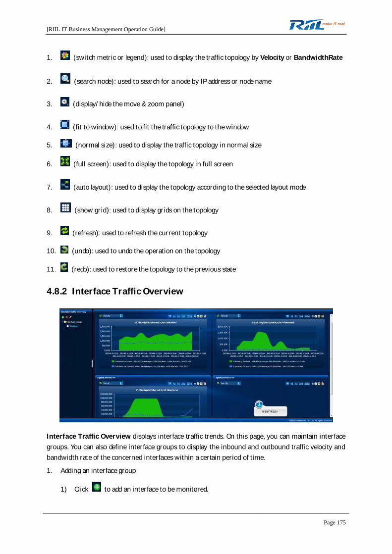
[RIIL IT Business Management Operation Guide]
Page 175
1. (switch metric or legend): used to display the traffic topology by Velocity or BandwidthRate
2. (search node): used to search for a node by IP address or node name
3. (display/hide the move & zoom panel)
4. (fit to window): used to fit the traffic topology to the window
5. (normal size): used to display the traffic topology in normal size
6. (full screen): used to display the topology in full screen
7. (auto layout): used to display the topology according to the selected layout mode
8. (show grid): used to display grids on the topology
9. (refresh): used to refresh the current topology
10. (undo): used to undo the operation on the topology
11. (redo): used to restore the topology to the previous state
4.8.2 Interface Traffic Overview
Interface Traffic Overview displays interface traffic trends. On this page, you can maintain interfacegroups. You can also define interface groups to display the inbound and outbound traffic velocity andbandwidth rate of the concerned interfaces within a certain period of time.
1. Adding an interface group
1) Click to add an interface to be monitored.

[RIIL IT Business Management Operation Guide]
Page 176
2) Enter the interface group name and select the device interfaces to be monitored. (Amaximum of 10 interfaces can be added to an interface group.)
3) Click to create the interface group.
2. Deleting an interface group
1) Select an interface group to be deleted. The interface group name is highlighted.
2) Click to delete the selected interface group.
3. Modifying an interface group
1) Select an interface group to be modified. The interface group name is highlighted.
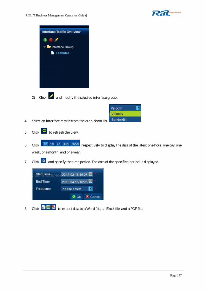
[RIIL IT Business Management Operation Guide]
Page 177
2) Click and modify the selected interface group.
4. Select an interface metric from the drop-down list .
5. Click to refresh the view.
6. Click respectively to display the data of the latest one hour, one day, one
week, one month, and one year.
7. Click and specify the time period. The data of the specified period is displayed.
8. Click to export data to a Word file, an Excel file, and a PDF file.

[RIIL IT Business Management Operation Guide]
Page 178
4.8.3 TOPN
RIIL can display the terminal, application, session, protocol, IP grouping, and VPN traffic rankings.
1. Select time in the drop-down list , and the data of the specified period is
displayed.
2. Click and set related parameters.
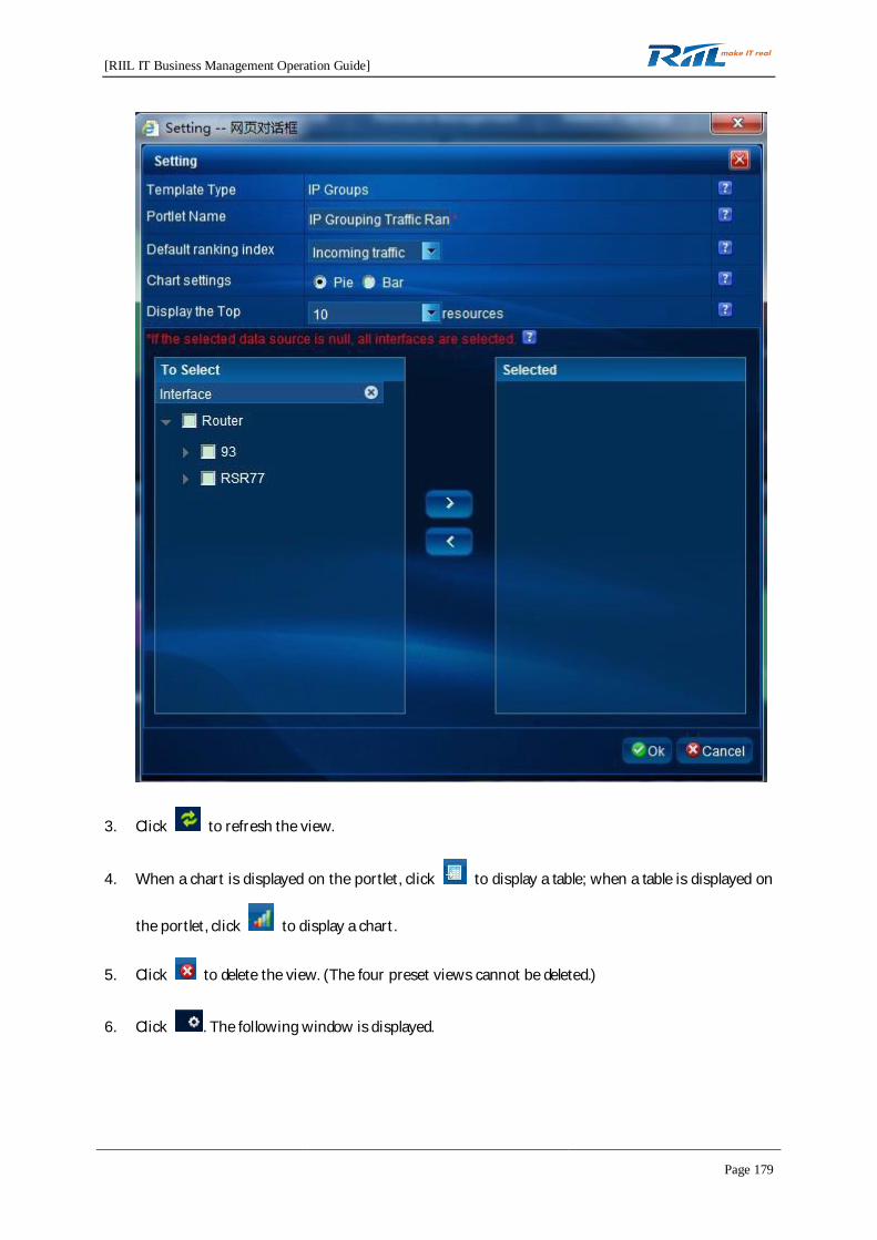
[RIIL IT Business Management Operation Guide]
Page 179
3. Click to refresh the view.
4. When a chart is displayed on the portlet, click to display a table; when a table is displayed on
the portlet, click to display a chart.
5. Click to delete the view. (The four preset views cannot be deleted.)
6. Click . The following window is displayed.
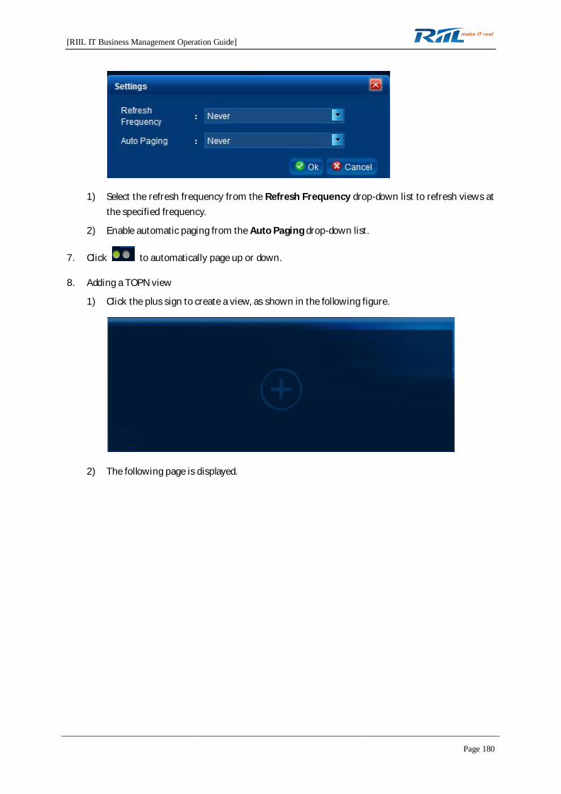
[RIIL IT Business Management Operation Guide]
Page 180
1) Select the refresh frequency from the Refresh Frequency drop-down list to refresh views atthe specified frequency.
2) Enable automatic paging from the Auto Paging drop-down list.
7. Click to automatically page up or down.
8. Adding a TOPN view
1) Click the plus sign to create a view, as shown in the following figure.
2) The following page is displayed.

[RIIL IT Business Management Operation Guide]
Page 181
3) Select the template type, as shown in the following figure.
4) Specify Portlet Name, Default ranking in, Chart settings, and Display the Top resources,and then click Ok.
9. When the top resources are displayed in a table, click a metric in the table header, and theresources are ranked according to the selected metric. Additionally, when you switch the displayformat, the statistic chart of the selected metric is displayed.
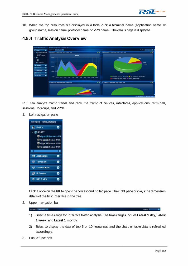
[RIIL IT Business Management Operation Guide]
Page 182
10. When the top resources are displayed in a table, click a terminal name (application name, IPgroup name, session name, protocol name, or VPN name). The details page is displayed.
4.8.4 Traffic Analysis Overview
RIIL can analyze traffic trends and rank the traffic of devices, interfaces, applications, terminals,sessions, IP groups, and VPNs.
1. Left navigation pane
Click a node on the left to open the corresponding tab page. The right pane displays the dimensiondetails of the first interface in the tree.
2. Upper navigation bar
1) Select a time range for interface traffic analysis. The time ranges include Latest 1 day, Latest1 week, and Latest 1 month.
2) Select to display the data of top 5 or 10 resources, and the chart or table data is refreshedaccordingly.
3. Public functions
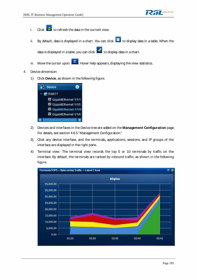
[RIIL IT Business Management Operation Guide]
Page 183
i. Click to refresh the data in the current view.
ii. By default, data is displayed in a chart. You can click to display data in a table. When the
data is displayed in a table, you can click to display data in a chart.
iii. Move the cursor upon . Hover help appears, displaying the view statistics.
4. Device dimension
1) Click Device, as shown in the following figure.
2) Devices and interfaces in the Device tree are added on the Management Configuration page.For details, see section 4.8.5 "Management Configuration."
3) Click any device interface, and the terminals, applications, sessions, and IP groups of theinterface are displayed in the right pane.
4) Terminal view: The terminal view records the top 5 or 10 terminals by traffic on theinterface. By default, the terminals are ranked by inbound traffic, as shown in the followingfigure.
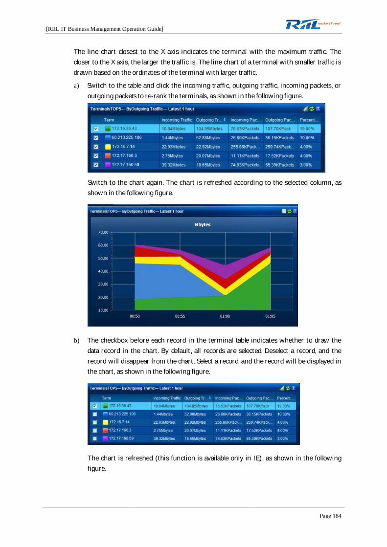
[RIIL IT Business Management Operation Guide]
Page 184
The line chart closest to the X axis indicates the terminal with the maximum traffic. Thecloser to the X axis, the larger the traffic is. The line chart of a terminal with smaller traffic isdrawn based on the ordinates of the terminal with larger traffic.
a) Switch to the table and click the incoming traffic, outgoing traffic, incoming packets, oroutgoing packets to re-rank the terminals, as shown in the following figure.
Switch to the chart again. The chart is refreshed according to the selected column, asshown in the following figure.
b) The checkbox before each record in the terminal table indicates whether to draw thedata record in the chart. By default, all records are selected. Deselect a record, and therecord will disappear from the chart. Select a record, and the record will be displayed inthe chart, as shown in the following figure.
The chart is refreshed (this function is available only in IE), as shown in the followingfigure.
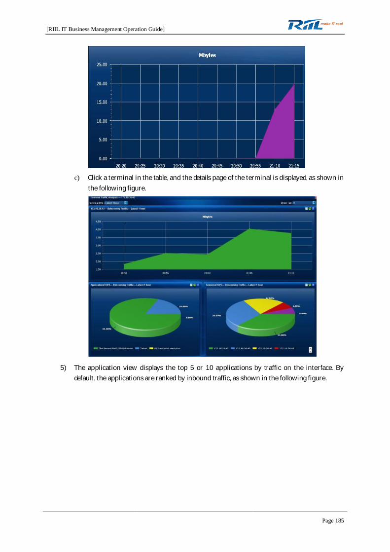
[RIIL IT Business Management Operation Guide]
Page 185
c) Click a terminal in the table, and the details page of the terminal is displayed, as shown inthe following figure.
5) The application view displays the top 5 or 10 applications by traffic on the interface. Bydefault, the applications are ranked by inbound traffic, as shown in the following figure.
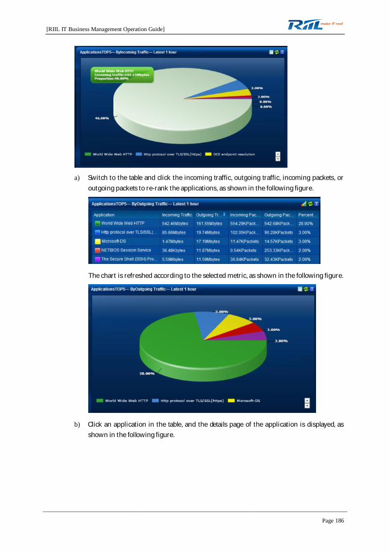
[RIIL IT Business Management Operation Guide]
Page 186
a) Switch to the table and click the incoming traffic, outgoing traffic, incoming packets, oroutgoing packets to re-rank the applications, as shown in the following figure.
The chart is refreshed according to the selected metric, as shown in the following figure.
b) Click an application in the table, and the details page of the application is displayed, asshown in the following figure.

[RIIL IT Business Management Operation Guide]
Page 187
6) The session view displays the top 5 or 10 sessions by traffic on the interface. By default, thesessions are ranked by inbound traffic, as shown in the following figure.
a) Switch to the table and click the incoming traffic, outgoing traffic, incoming packets, oroutgoing packets to re-rank the sessions, as shown in the following figure.
The chart is refreshed according to the selected metric, as shown in the following figure.
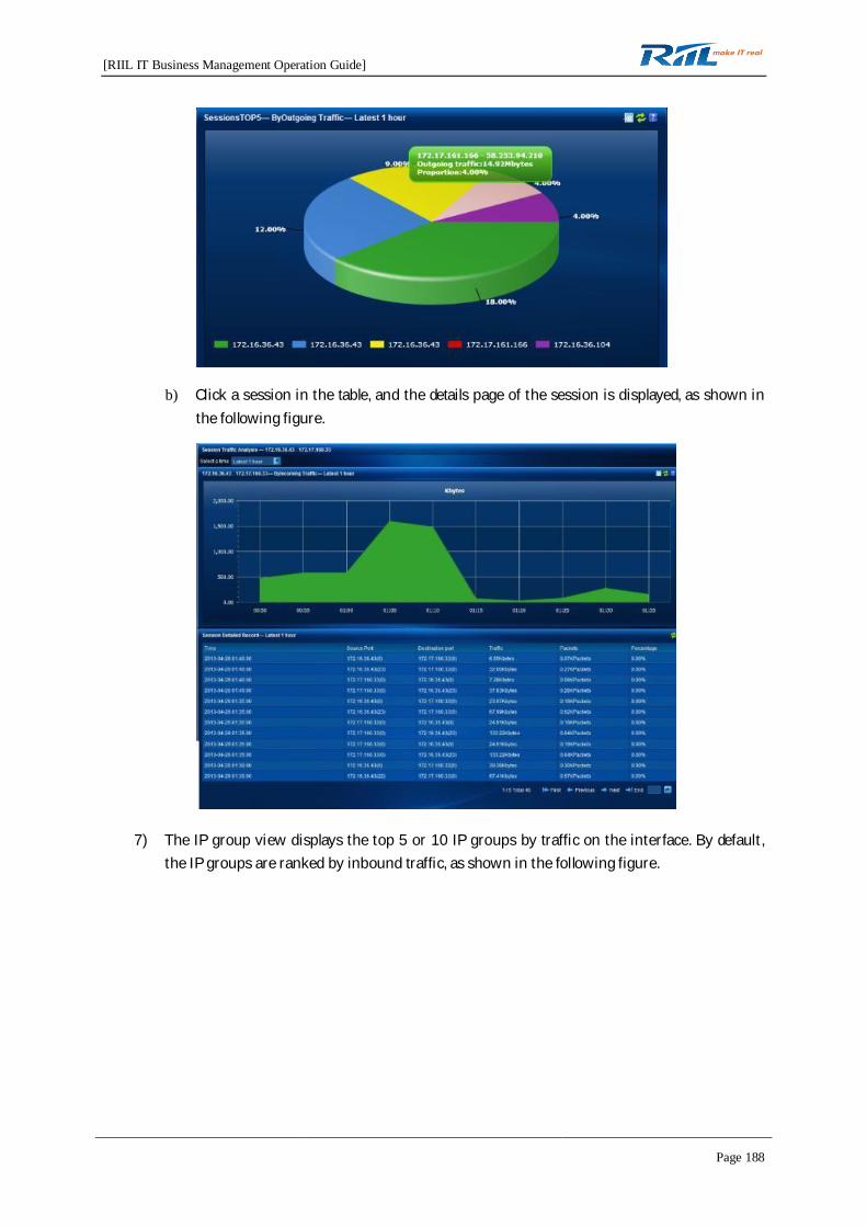
[RIIL IT Business Management Operation Guide]
Page 188
b) Click a session in the table, and the details page of the session is displayed, as shown inthe following figure.
7) The IP group view displays the top 5 or 10 IP groups by traffic on the interface. By default,the IP groups are ranked by inbound traffic, as shown in the following figure.

[RIIL IT Business Management Operation Guide]
Page 189
a) Switch to the table and click the incoming traffic, outgoing traffic, incoming packets, oroutgoing packets to re-rank the IP groups, as shown in the following figure.
The chart is refreshed according to the selected metric, as shown in the following figure.
b) Click an IP group in the table, and the details page of the IP group is displayed, as shownin the following figure.
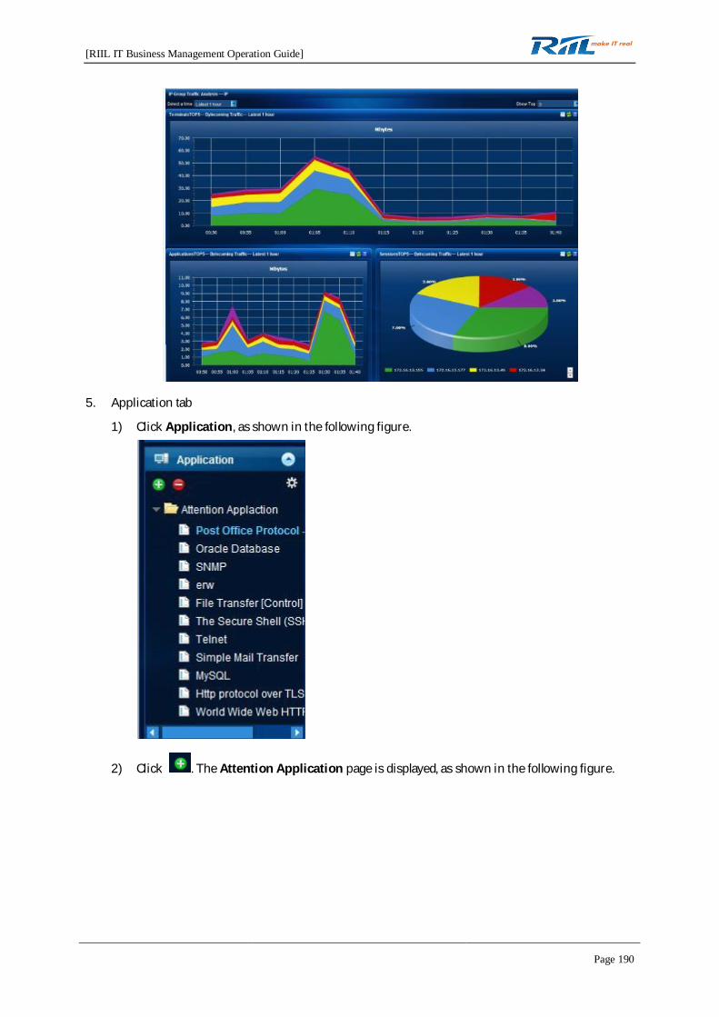
[RIIL IT Business Management Operation Guide]
Page 190
5. Application tab
1) Click Application, as shown in the following figure.
2) Click . The Attention Application page is displayed, as shown in the following figure.
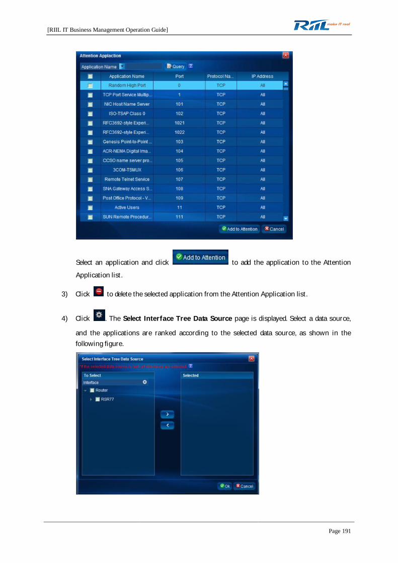
[RIIL IT Business Management Operation Guide]
Page 191
Select an application and click to add the application to the Attention
Application list.
3) Click to delete the selected application from the Attention Application list.
4) Click . The Select Interface Tree Data Source page is displayed. Select a data source,
and the applications are ranked according to the selected data source, as shown in thefollowing figure.
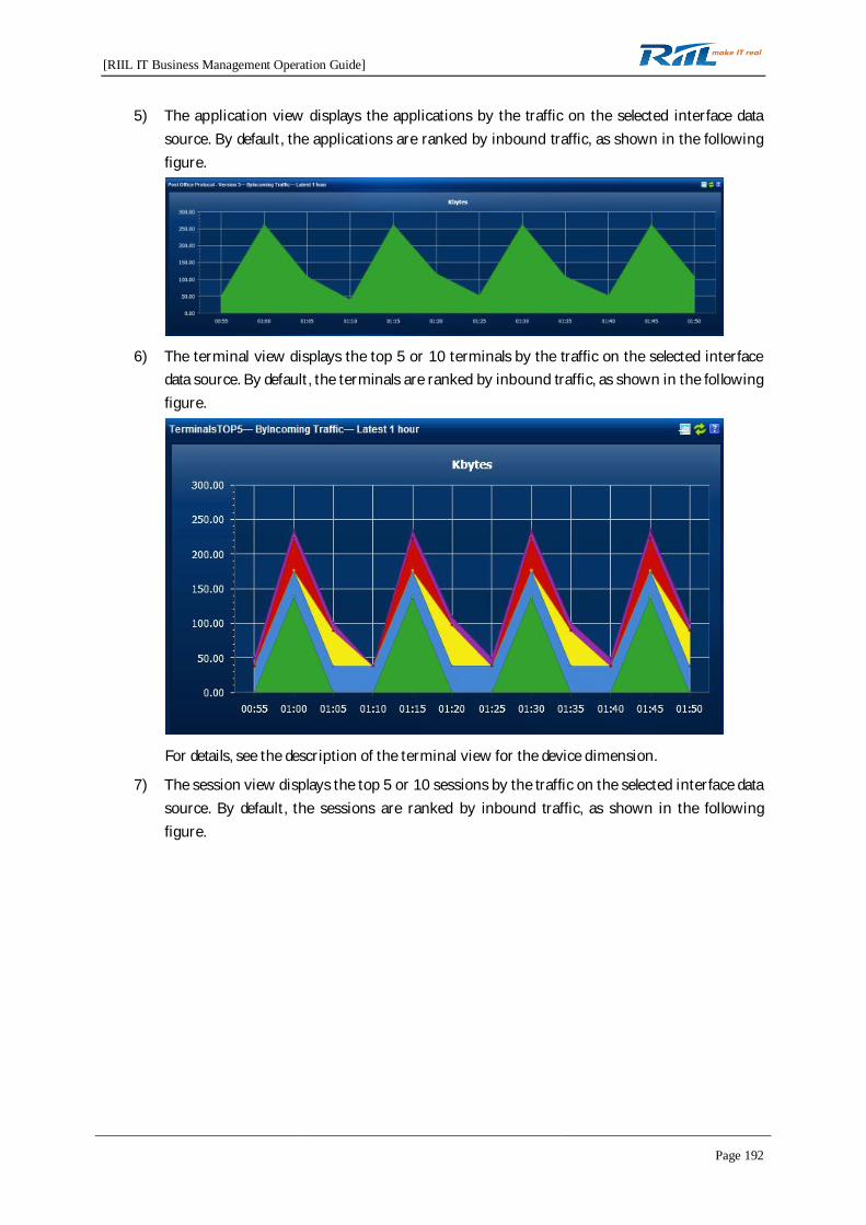
[RIIL IT Business Management Operation Guide]
Page 192
5) The application view displays the applications by the traffic on the selected interface datasource. By default, the applications are ranked by inbound traffic, as shown in the followingfigure.
6) The terminal view displays the top 5 or 10 terminals by the traffic on the selected interfacedata source. By default, the terminals are ranked by inbound traffic, as shown in the followingfigure.
For details, see the description of the terminal view for the device dimension.
7) The session view displays the top 5 or 10 sessions by the traffic on the selected interface datasource. By default, the sessions are ranked by inbound traffic, as shown in the followingfigure.

[RIIL IT Business Management Operation Guide]
Page 193
For details, see the description of the session view for the device dimension.
6. Terminal tab
1) Click Terminal, as shown in the following figure.
2) Click to display the top N tree, as shown in the following figure.
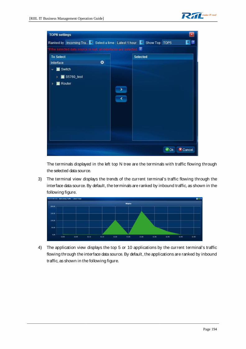
[RIIL IT Business Management Operation Guide]
Page 194
The terminals displayed in the left top N tree are the terminals with traffic flowing throughthe selected data source.
3) The terminal view displays the trends of the current terminal's traffic flowing through theinterface data source. By default, the terminals are ranked by inbound traffic, as shown in thefollowing figure.
4) The application view displays the top 5 or 10 applications by the current terminal's trafficflowing through the interface data source. By default, the applications are ranked by inboundtraffic, as shown in the following figure.

[RIIL IT Business Management Operation Guide]
Page 195
For details, see the description of the application view for the device dimension.
5) The session view displays the top 5 or 10 sessions by the current terminal's traffic flowingthrough the interface data source. By default, the sessions are ranked by inbound traffic, asshown in the following figure.
For details, see the description of the application view for the device dimension.
7. Session dimension
1) Click Conversation, as shown in the following figure.
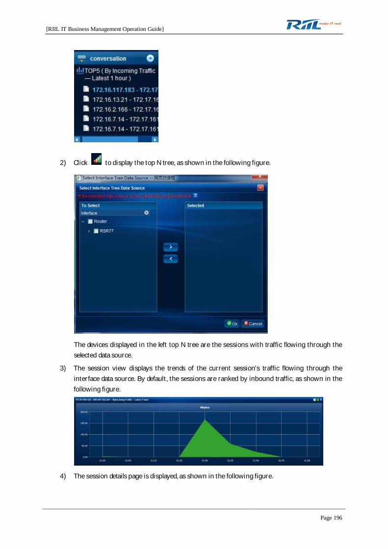
[RIIL IT Business Management Operation Guide]
Page 196
2) Click to display the top N tree, as shown in the following figure.
The devices displayed in the left top N tree are the sessions with traffic flowing through theselected data source.
3) The session view displays the trends of the current session's traffic flowing through theinterface data source. By default, the sessions are ranked by inbound traffic, as shown in thefollowing figure.
4) The session details page is displayed, as shown in the following figure.

[RIIL IT Business Management Operation Guide]
Page 197
8. IP group dimension
1) Click IP Groups, as shown in the following figure.
2) Click to add an IP group, as shown in the following figure.
3) Click to delete an IP group.
4) Select an IP group and click to modify the parameter settings of the IP group.
5) Click . The Select Interface Tree Data Source page is displayed. Select a data source, and
the applications are ranked according to the selected data source.

[RIIL IT Business Management Operation Guide]
Page 198
6) The IP group view displays the top 5 or 10 terminals by the current IP group's traffic flowingthrough the interface data source. By default, the terminals are ranked by inbound traffic, asshown in the following figure.
For details, see the description of the terminal view for the device dimension.
7) The application view displays the top 5 or 10 applications by the current IP group's trafficflowing through the interface data source. By default, the applications are ranked by inboundtraffic, as shown in the following figure.

[RIIL IT Business Management Operation Guide]
Page 199
For details, see the description of the terminal view for the device dimension.
8) The session view displays the top 5 or 10 sessions by the current IP group's traffic flowingthrough the interface data source. By default, the sessions are ranked by inbound traffic, asshown in the following figure.
For details, see the description of the session view for the device dimension.
9. MPLS VPN dimension
1) Click MPLS VPN, as shown in the following figure. For VPN settings, see interface settings insection 4.8.5 "Management Configuration."
2) The VPN view displays the traffic trend of the current VPN. By default, the VPNs are rankedby inbound traffic, as shown in the following figure.
3) The terminal view displays the top 5 or 10 terminals by traffic flowing through the VPN. Bydefault, the terminals are ranked by inbound traffic, as shown in the following figure.
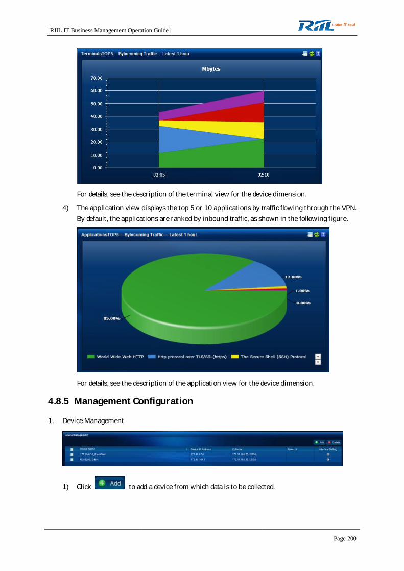
[RIIL IT Business Management Operation Guide]
Page 200
For details, see the description of the terminal view for the device dimension.
4) The application view displays the top 5 or 10 applications by traffic flowing through the VPN.By default, the applications are ranked by inbound traffic, as shown in the following figure.
For details, see the description of the application view for the device dimension.
4.8.5 Management Configuration
1. Device Management
1) Click to add a device from which data is to be collected.
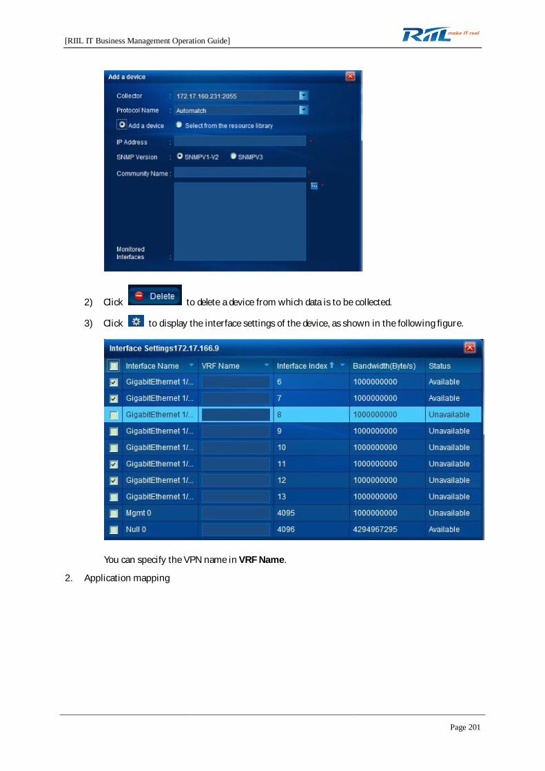
[RIIL IT Business Management Operation Guide]
Page 201
2) Click to delete a device from which data is to be collected.
3) Click to display the interface settings of the device, as shown in the following figure.
You can specify the VPN name in VRF Name.
2. Application mapping

[RIIL IT Business Management Operation Guide]
Page 202
1) Click to add application mapping.
4) Select an application and click to delete the application mapping.
5) Click to restore the application mapping to the default
application mapping.
6) Select an application not in the Attention Application list and click toadd the application to the list.
7) Select an application in the Attention Application list and click to
delete the application from the list.
3. Manage IP Group
1) To create an IP group, click .
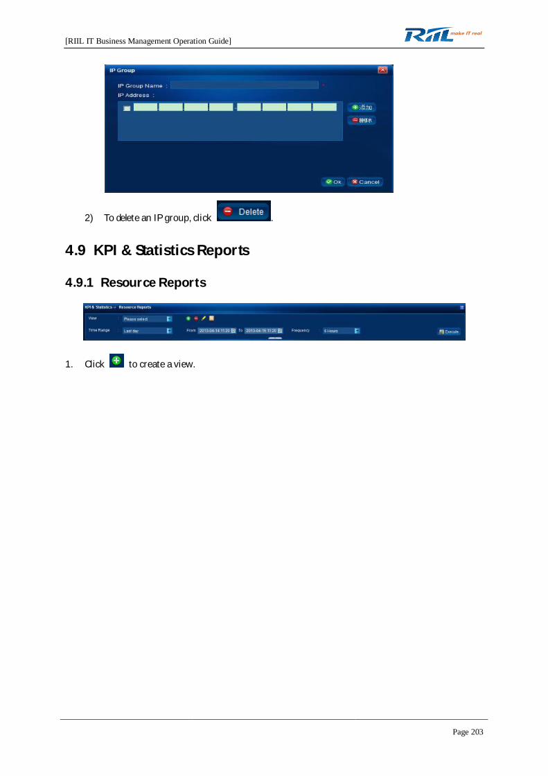
[RIIL IT Business Management Operation Guide]
Page 203
2) To delete an IP group, click .
4.9 KPI & Statistics Reports
4.9.1 Resource Reports
1. Click to create a view.
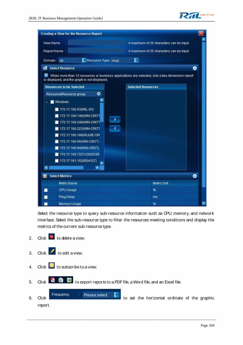
[RIIL IT Business Management Operation Guide]
Page 204
Select the resource type to query sub-resource information such as CPU, memory, and networkinterface. Select the sub-resource type to filter the resources meeting conditions and display themetrics of the current sub-resource type.
2. Click to delete a view.
3. Click to edit a view.
4. Click to subscribe to a view.
5. Click to export reports to a PDF file, a Word file, and an Excel file.
6. Click to set the horizontal ordinate of the graphicreport.
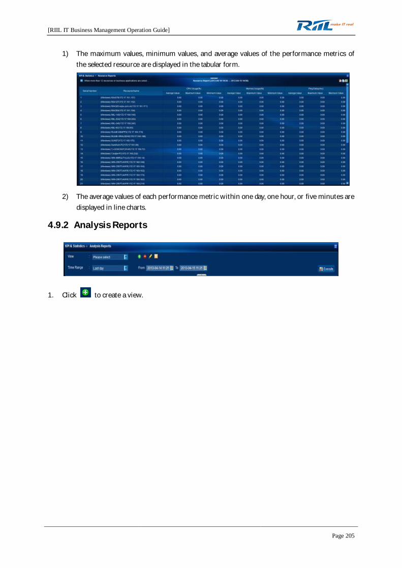
[RIIL IT Business Management Operation Guide]
Page 205
1) The maximum values, minimum values, and average values of the performance metrics ofthe selected resource are displayed in the tabular form.
2) The average values of each performance metric within one day, one hour, or five minutes aredisplayed in line charts.
4.9.2 Analysis Reports
1. Click to create a view.

[RIIL IT Business Management Operation Guide]
Page 206
1) Click . The setting page is displayed.
2) Click . The Default Settings page is displayed.

[RIIL IT Business Management Operation Guide]
Page 207
2. Click to delete a view.
3. Click to edit a view.
4. Click to subscribe to a view.
5. Click to export reports to a PDF file, a Word file, and an Excel file.
6. The metric values and the differences between the values and the expected values are displayedin tables and bar charts.
4.9.3 Trend Reports
1. Click to create a view.
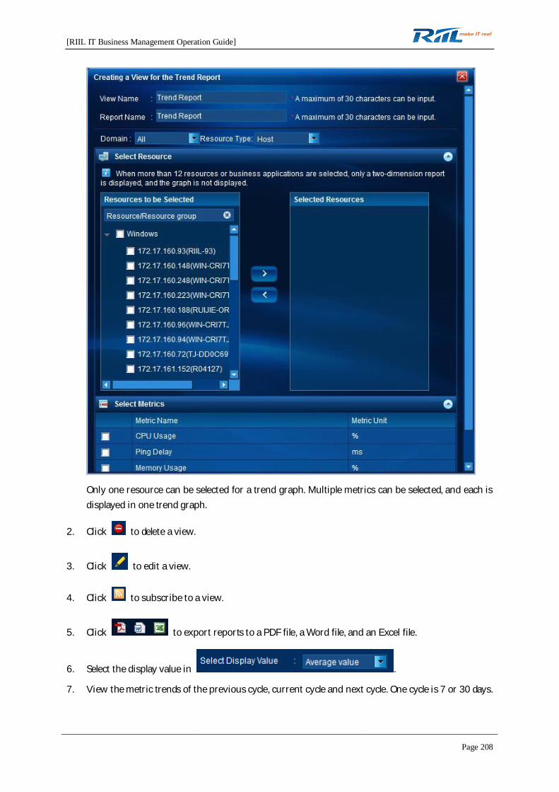
[RIIL IT Business Management Operation Guide]
Page 208
Only one resource can be selected for a trend graph. Multiple metrics can be selected, and each isdisplayed in one trend graph.
2. Click to delete a view.
3. Click to edit a view.
4. Click to subscribe to a view.
5. Click to export reports to a PDF file, a Word file, and an Excel file.
6. Select the display value in .
7. View the metric trends of the previous cycle, current cycle and next cycle. One cycle is 7 or 30 days.
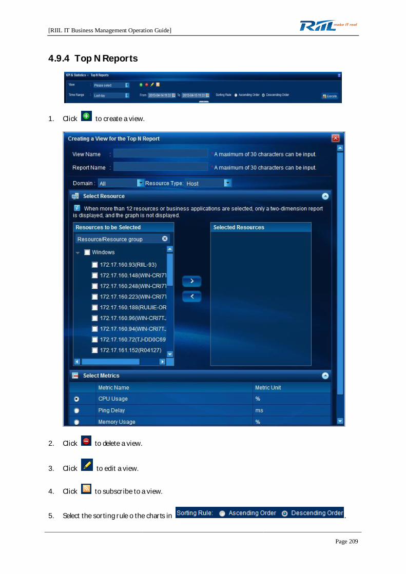
[RIIL IT Business Management Operation Guide]
Page 209
4.9.4 Top N Reports
1. Click to create a view.
2. Click to delete a view.
3. Click to edit a view.
4. Click to subscribe to a view.
5. Select the sorting rule o the charts in .

[RIIL IT Business Management Operation Guide]
Page 210
6. Click to export reports to a PDF file, a Word file, and an Excel file.
7. Top N rankings are displayed in descending or ascending order in the two-dimensional table andbar chart. If more than 12 resources or services are selected, only the two-dimensional report isdisplayed, and the pie chart is not displayed, as shown in the following figure.
4.9.5 Fault Reports
1. Click to create a view.
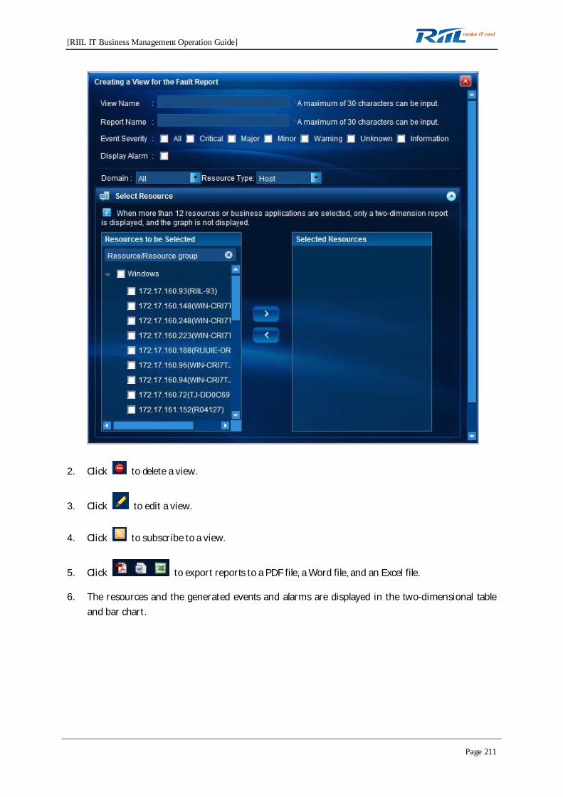
[RIIL IT Business Management Operation Guide]
Page 211
2. Click to delete a view.
3. Click to edit a view.
4. Click to subscribe to a view.
5. Click to export reports to a PDF file, a Word file, and an Excel file.
6. The resources and the generated events and alarms are displayed in the two-dimensional tableand bar chart.
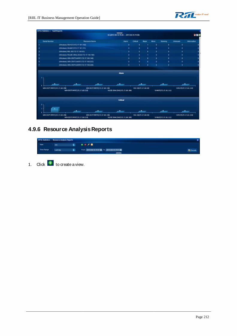
[RIIL IT Business Management Operation Guide]
Page 212
4.9.6 Resource Analysis Reports
1. Click to create a view.

[RIIL IT Business Management Operation Guide]
Page 213
1) Click . The setting page is displayed.
2) Click . The Default Settings page is displayed.
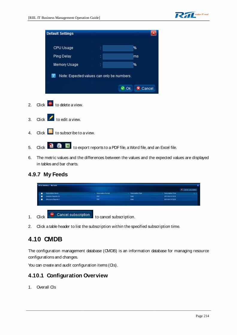
[RIIL IT Business Management Operation Guide]
Page 214
2. Click to delete a view.
3. Click to edit a view.
4. Click to subscribe to a view.
5. Click to export reports to a PDF file, a Word file, and an Excel file.
6. The metric values and the differences between the values and the expected values are displayedin tables and bar charts.
4.9.7 My Feeds
1. Click to cancel subscription.
2. Click a table header to list the subscription within the specified subscription time.
4.10 CMDB
The configuration management database (CMDB) is an information database for managing resourceconfigurations and changes.
You can create and audit configuration items (CIs).
4.10.1 Configuration Overview
1. Overall CIs
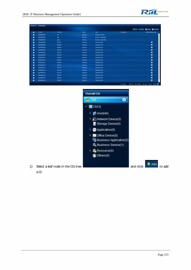
[RIIL IT Business Management Operation Guide]
Page 215
1) Select a leaf node in the CIs tree and click to adda CI.
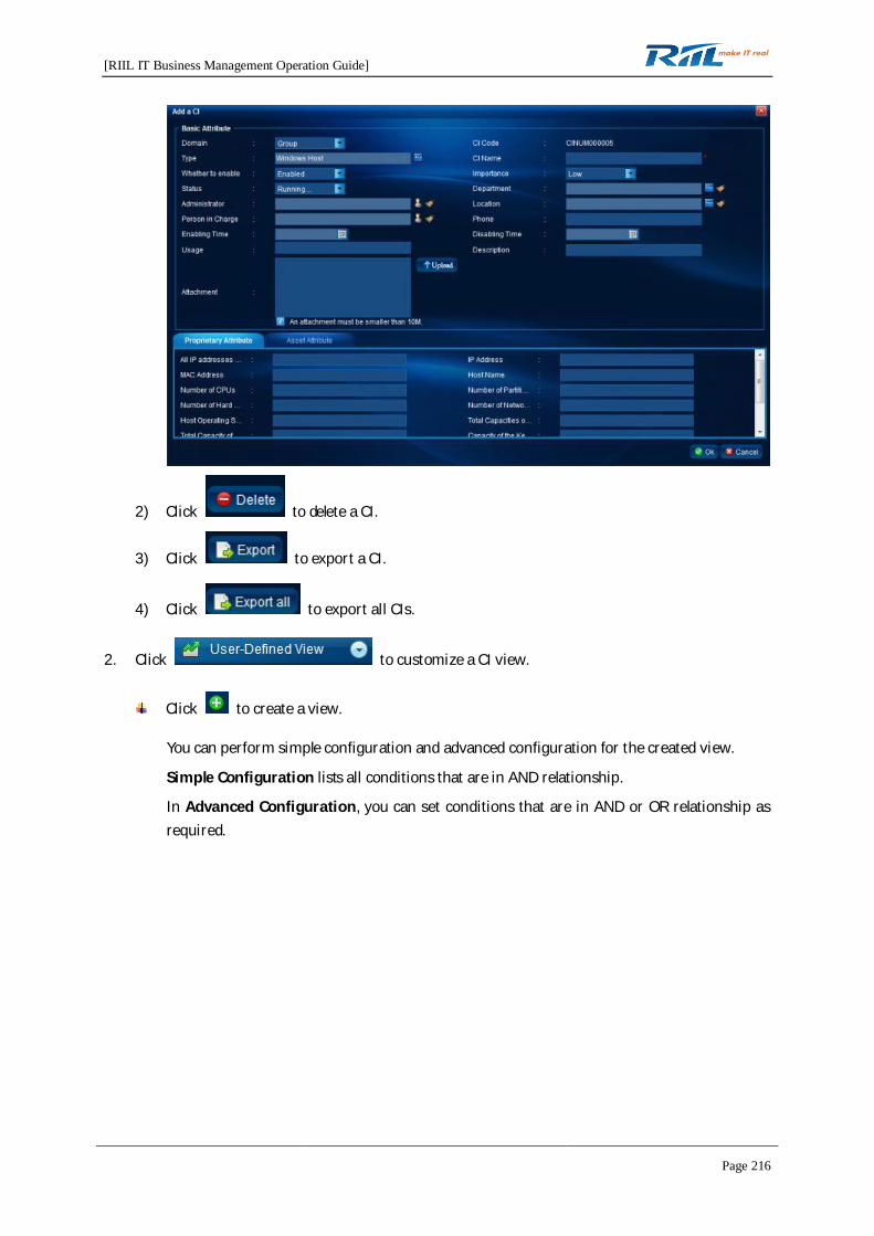
[RIIL IT Business Management Operation Guide]
Page 216
2) Click to delete a CI.
3) Click to export a CI.
4) Click to export all CIs.
2. Click to customize a CI view.
Click to create a view.
You can perform simple configuration and advanced configuration for the created view.
Simple Configuration lists all conditions that are in AND relationship.
In Advanced Configuration, you can set conditions that are in AND or OR relationship asrequired.
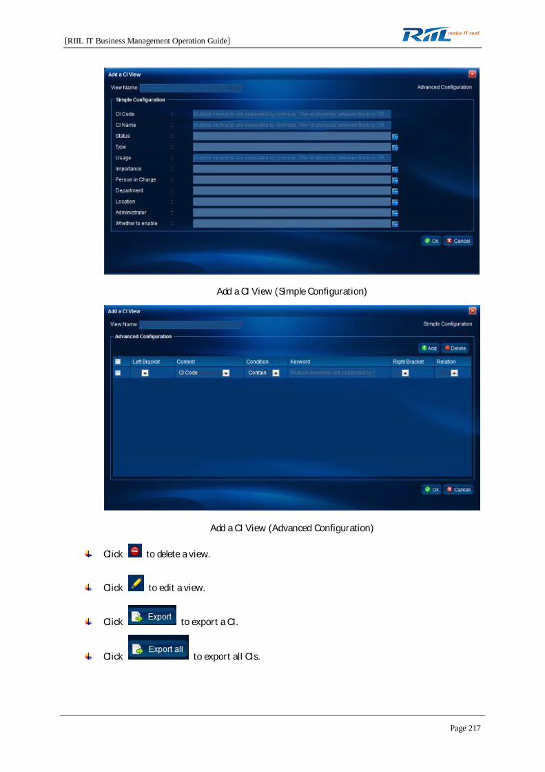
[RIIL IT Business Management Operation Guide]
Page 217
Add a CI View (Simple Configuration)
Add a CI View (Advanced Configuration)
Click to delete a view.
Click to edit a view.
Click to export a CI.
Click to export all CIs.

[RIIL IT Business Management Operation Guide]
Page 218
4.10.1.1 Structure Chart
A newly created CI has only the current CI node that is highlighted.
4.10.1.2 Browsing a View
1. The view displays the logical relationship between the current CI and all other CIs.
2. Eagle eye: can be dragged to zoom in or out the structure chart.
3. Thumbnail image: appears only when a part of the chart is zoomed in to over 100%. You can usethe thumbnail image for locating.
4. The current CI is highlighted.
5. Toolbar:
1) : used to switch to the edit page
2) : used to display the structure chart in its actual size
3) : used to fit the structure chart to the size of the window
4) : used to display the structure chart in full screen
5) : used to refresh the structure chart
6) : used to search for and highlight a CI in the structure chart
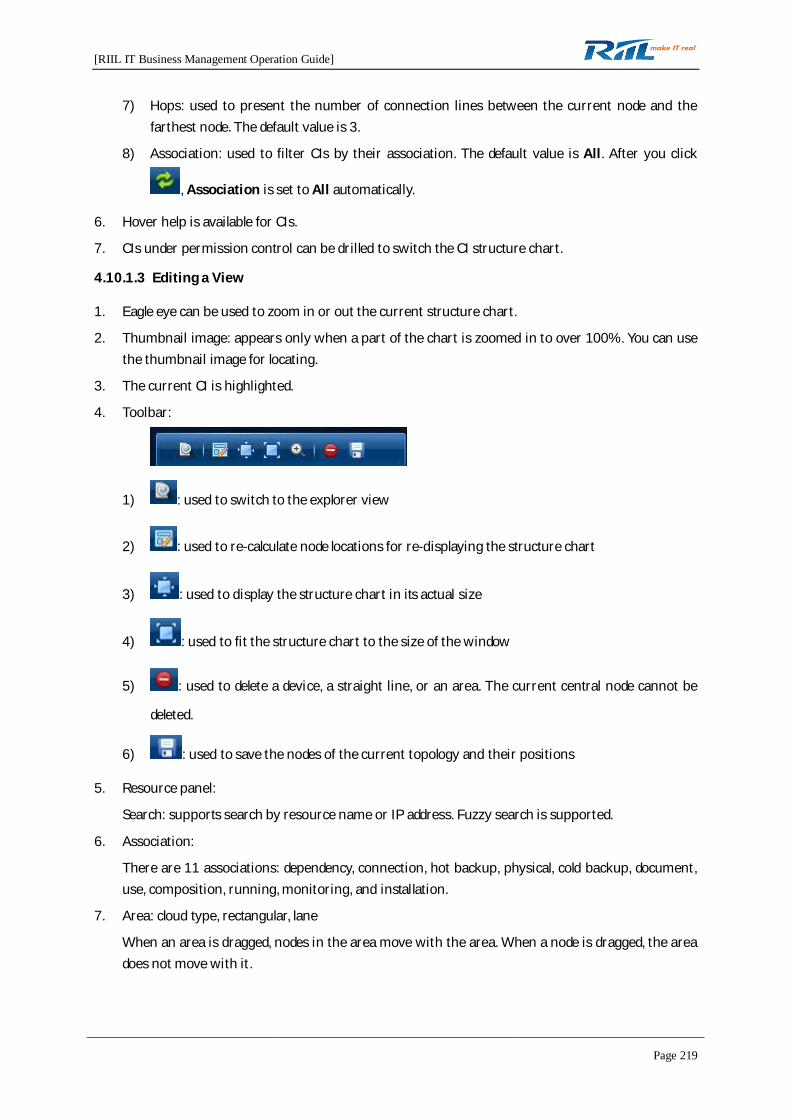
[RIIL IT Business Management Operation Guide]
Page 219
7) Hops: used to present the number of connection lines between the current node and thefarthest node. The default value is 3.
8) Association: used to filter CIs by their association. The default value is All. After you click
, Association is set to All automatically.
6. Hover help is available for CIs.
7. CIs under permission control can be drilled to switch the CI structure chart.
4.10.1.3 Editing a View
1. Eagle eye can be used to zoom in or out the current structure chart.
2. Thumbnail image: appears only when a part of the chart is zoomed in to over 100%. You can usethe thumbnail image for locating.
3. The current CI is highlighted.
4. Toolbar:
1) : used to switch to the explorer view
2) : used to re-calculate node locations for re-displaying the structure chart
3) : used to display the structure chart in its actual size
4) : used to fit the structure chart to the size of the window
5) : used to delete a device, a straight line, or an area. The current central node cannot be
deleted.
6) : used to save the nodes of the current topology and their positions
5. Resource panel:
Search: supports search by resource name or IP address. Fuzzy search is supported.
6. Association:
There are 11 associations: dependency, connection, hot backup, physical, cold backup, document,use, composition, running, monitoring, and installation.
7. Area: cloud type, rectangular, lane
When an area is dragged, nodes in the area move with the area. When a node is dragged, the areadoes not move with it.

[RIIL IT Business Management Operation Guide]
Page 220
4.10.1.4 Change History
1. Manually change the CI attributes and click Apply. A version change record is generated, andChanging Method changes to Manual.
2. Change the CI attributes through auditing. A version change record is generated, and ChangingMethod changes to Automatic.
4.10.2 Auditing CIs
4.10.2.1 Auditing Tasks
1. Display conventions:
Common users can access only audit tasks created by them. The system administrator can viewall audit tasks but cannot edit or change them.
By default, audit tasks are sorted by Task Creating Time in descending order.
2. Click to add an audit task.
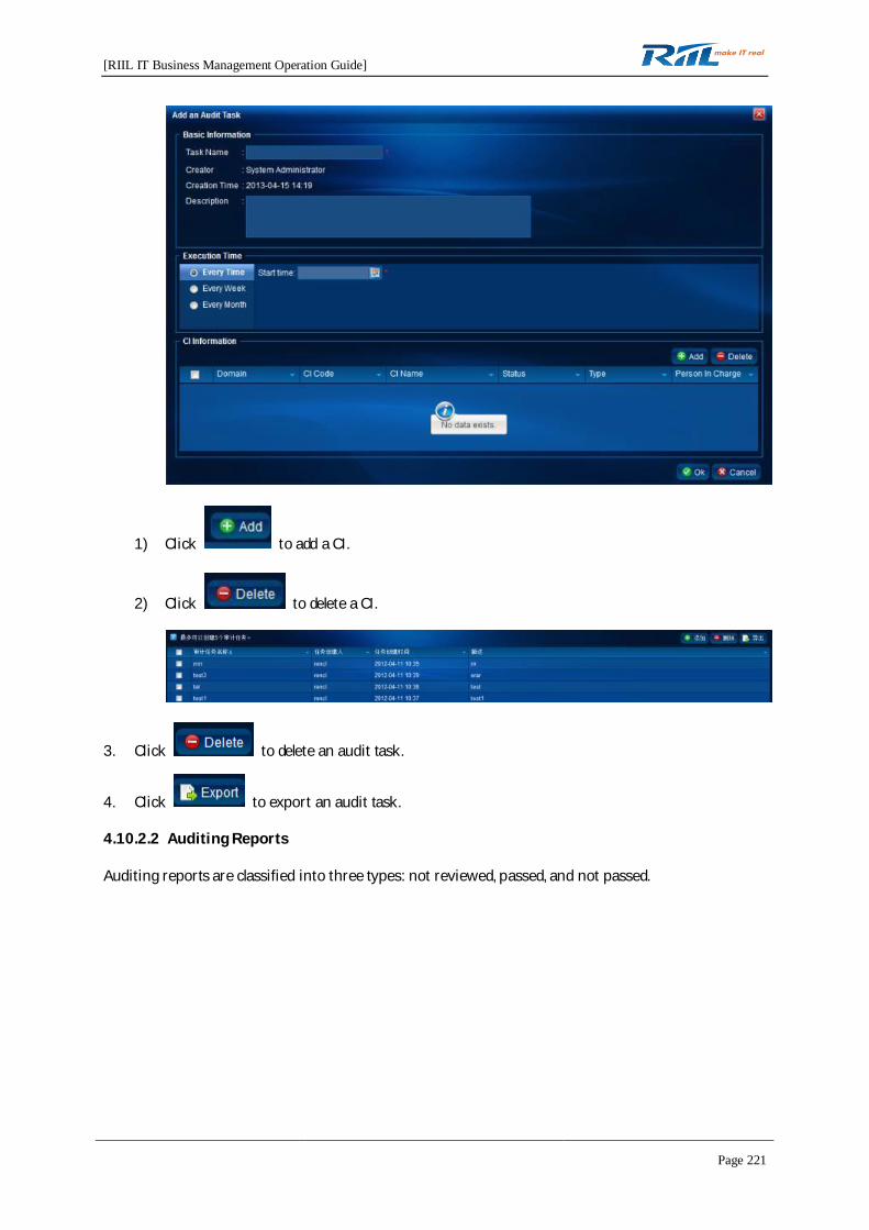
[RIIL IT Business Management Operation Guide]
Page 221
1) Click to add a CI.
2) Click to delete a CI.
3. Click to delete an audit task.
4. Click to export an audit task.
4.10.2.2 Auditing Reports
Auditing reports are classified into three types: not reviewed, passed, and not passed.
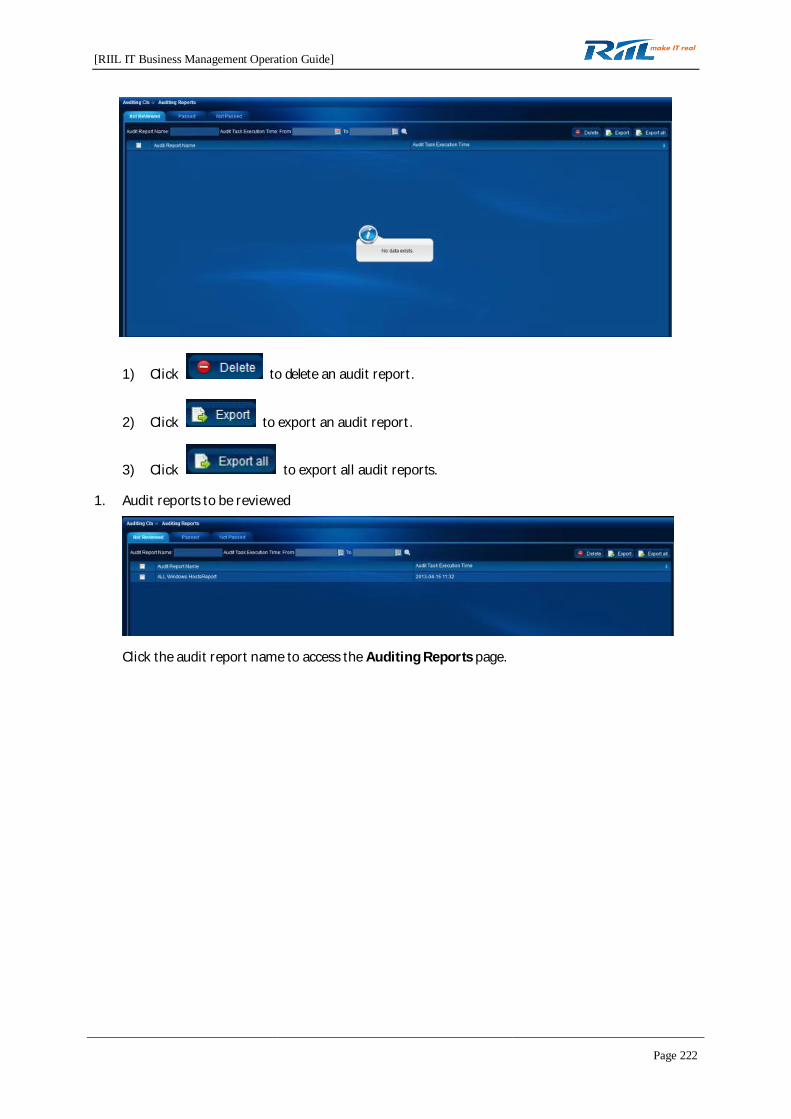
[RIIL IT Business Management Operation Guide]
Page 222
1) Click to delete an audit report.
2) Click to export an audit report.
3) Click to export all audit reports.
1. Audit reports to be reviewed
Click the audit report name to access the Auditing Reports page.
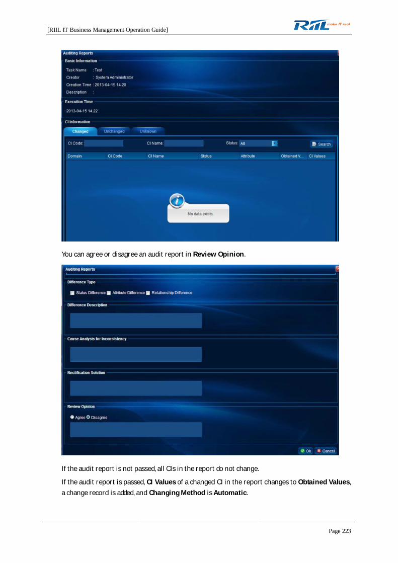
[RIIL IT Business Management Operation Guide]
Page 223
You can agree or disagree an audit report in Review Opinion.
If the audit report is not passed, all CIs in the report do not change.
If the audit report is passed, CI Values of a changed CI in the report changes to Obtained Values,a change record is added, and Changing Method is Automatic.
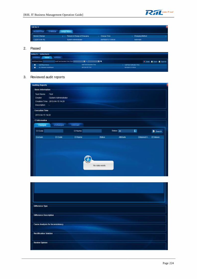
[RIIL IT Business Management Operation Guide]
Page 224
2. Passed
3. Reviewed audit reports

[RIIL IT Business Management Operation Guide]
Page 225
4. Not Passed
4.10.3 Configuration Wizard
The wizard will guide you through all CMDB configuration pages, including import, associating,allocating a domain, and configuring permissions. It will also help you to complete CMDB setting.
Click to start CMDB configuration.
4.10.3.1 Import
1. Allocate CI types to resources monitored by RIIL and import the resources to the CMDB.
2. Import data from the Excel file to the CMDB.
4.10.3.2 Automatic Import
Allocate CI types to resources monitored by RIIL and import the resources to the CMDB.
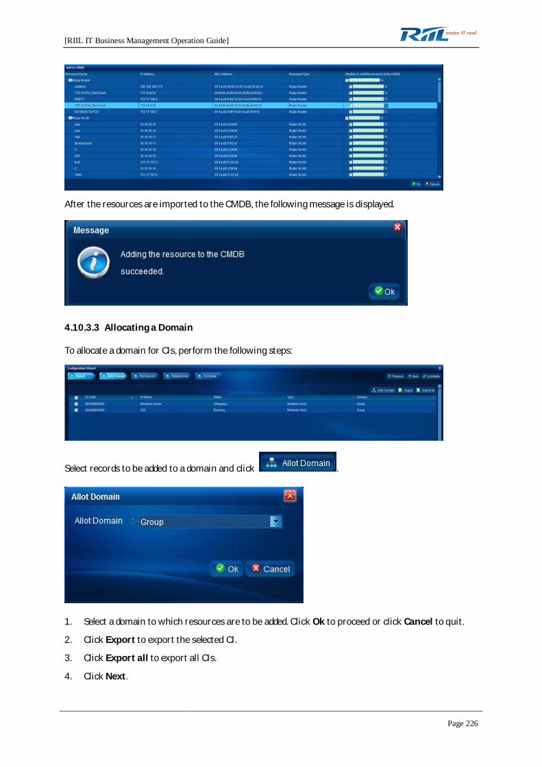
[RIIL IT Business Management Operation Guide]
Page 226
After the resources are imported to the CMDB, the following message is displayed.
4.10.3.3 Allocating a Domain
To allocate a domain for CIs, perform the following steps:
Select records to be added to a domain and click .
1. Select a domain to which resources are to be added. Click Ok to proceed or click Cancel to quit.
2. Click Export to export the selected CI.
3. Click Export all to export all CIs.
4. Click Next.

[RIIL IT Business Management Operation Guide]
Page 227
4.10.3.4 Permission Setting
1. Display CIs in the default workgroup.
2. Add CIs to a non-default workgroup and assign permissions (for proprietary attribute and asset
attribute). Click a non-default workgroup and click . The Add dialog box is displayed.
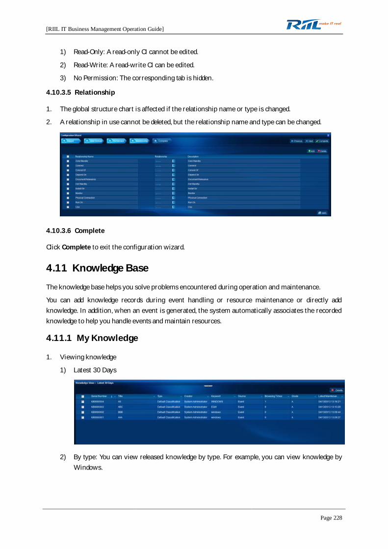
[RIIL IT Business Management Operation Guide]
Page 228
1) Read-Only: A read-only CI cannot be edited.
2) Read-Write: A read-write CI can be edited.
3) No Permission: The corresponding tab is hidden.
4.10.3.5 Relationship
1. The global structure chart is affected if the relationship name or type is changed.
2. A relationship in use cannot be deleted, but the relationship name and type can be changed.
4.10.3.6 Complete
Click Complete to exit the configuration wizard.
4.11 Knowledge Base
The knowledge base helps you solve problems encountered during operation and maintenance.
You can add knowledge records during event handling or resource maintenance or directly addknowledge. In addition, when an event is generated, the system automatically associates the recordedknowledge to help you handle events and maintain resources.
4.11.1 My Knowledge
1. Viewing knowledge
1) Latest 30 Days
2) By type: You can view released knowledge by type. For example, you can view knowledge byWindows.

[RIIL IT Business Management Operation Guide]
Page 229
3) Customize a view for released knowledge.
Click to add a knowledge view.
You can perform simple configuration and advanced configuration for the created view.
Simple Configuration: The conditions are in AND relationship.
Advanced Configuration: You can set conditions as required. The conditions are in ANDor OR relationship.
Simple Configuration
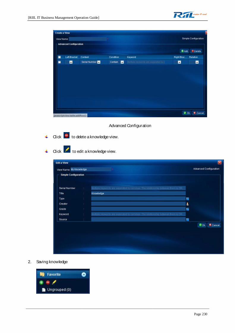
[RIIL IT Business Management Operation Guide]
Page 230
Advanced Configuration
Click to delete a knowledge view.
Click to edit a knowledge view.
2. Saving knowledge
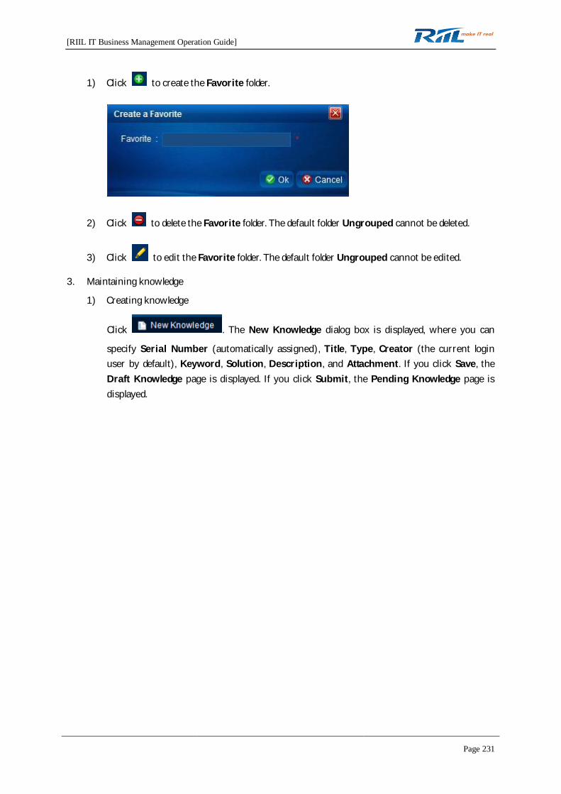
[RIIL IT Business Management Operation Guide]
Page 231
1) Click to create the Favorite folder.
2) Click to delete the Favorite folder. The default folder Ungrouped cannot be deleted.
3) Click to edit the Favorite folder. The default folder Ungrouped cannot be edited.
3. Maintaining knowledge
1) Creating knowledge
Click . The New Knowledge dialog box is displayed, where you can
specify Serial Number (automatically assigned), Title, Type, Creator (the current loginuser by default), Keyword, Solution, Description, and Attachment. If you click Save, theDraft Knowledge page is displayed. If you click Submit, the Pending Knowledge page isdisplayed.

[RIIL IT Business Management Operation Guide]
Page 232
2) Draft Knowledge
Click to delete knowledge.
3) Pending Knowledge
Click to delete knowledge.
4) Rejected Knowledge
Click to delete knowledge.

[RIIL IT Business Management Operation Guide]
Page 233
4.11.2 Knowledge Management
Only a knowledge administrator has permission to manage knowledge, including knowledge audit,knowledge statistics, and knowledge setting.
1. Knowledge Audit
1) When you click a knowledge record in the list, the Details page of the knowledge is displayed.The Details page displays Serial Number (unchangeable), Title, Type, Creator(unchangeable), Grade, Keyword, Solution, Description, and Attachment, as shown in thefollowing figure.
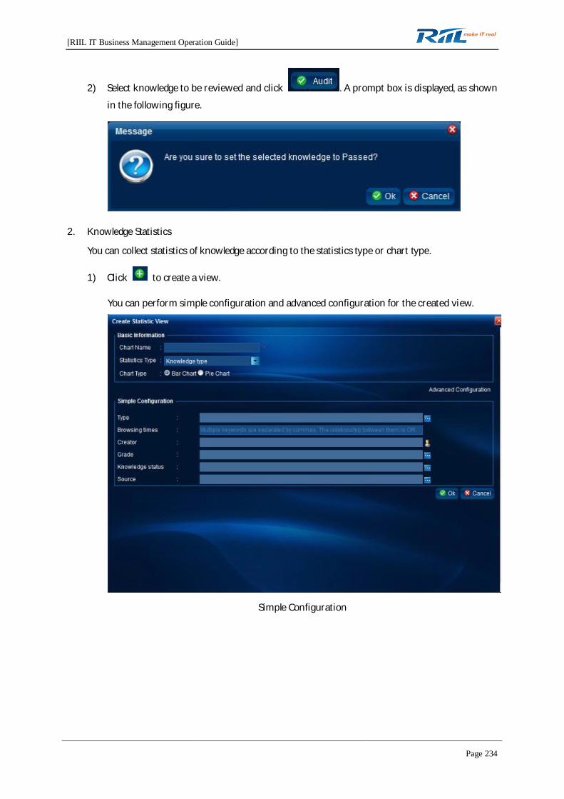
[RIIL IT Business Management Operation Guide]
Page 234
2) Select knowledge to be reviewed and click . A prompt box is displayed, as shown
in the following figure.
2. Knowledge Statistics
You can collect statistics of knowledge according to the statistics type or chart type.
1) Click to create a view.
You can perform simple configuration and advanced configuration for the created view.
Simple Configuration
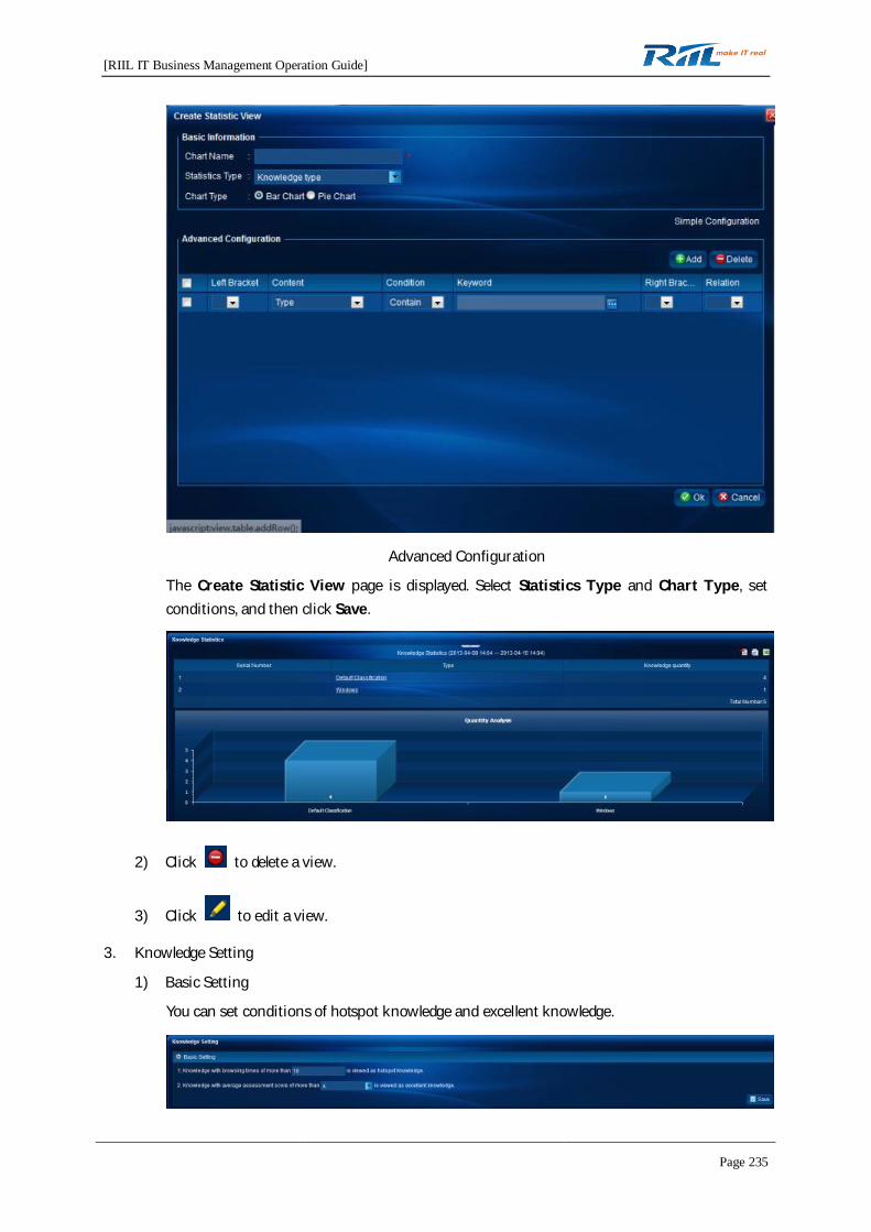
[RIIL IT Business Management Operation Guide]
Page 235
Advanced Configuration
The Create Statistic View page is displayed. Select Statistics Type and Chart Type, setconditions, and then click Save.
2) Click to delete a view.
3) Click to edit a view.
3. Knowledge Setting
1) Basic Setting
You can set conditions of hotspot knowledge and excellent knowledge.
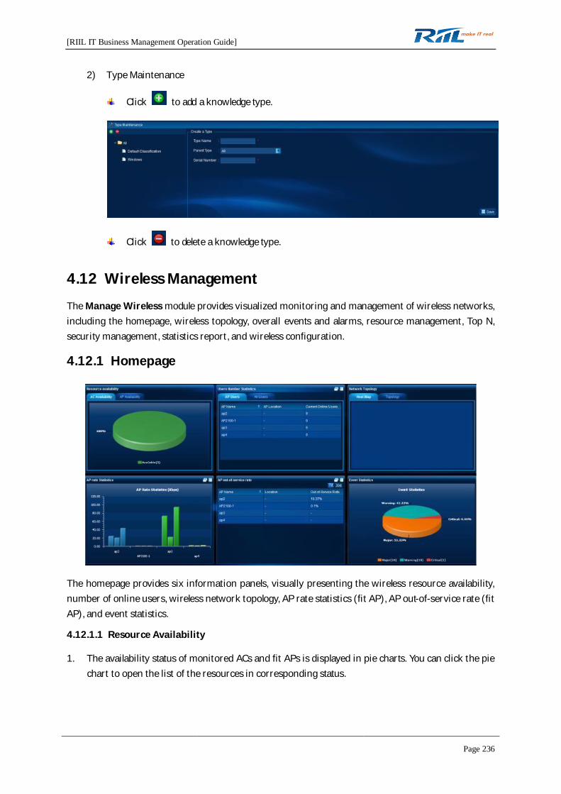
[RIIL IT Business Management Operation Guide]
Page 236
2) Type Maintenance
Click to add a knowledge type.
Click to delete a knowledge type.
4.12 Wireless Management
The Manage Wireless module provides visualized monitoring and management of wireless networks,including the homepage, wireless topology, overall events and alarms, resource management, Top N,security management, statistics report, and wireless configuration.
4.12.1 Homepage
The homepage provides six information panels, visually presenting the wireless resource availability,number of online users, wireless network topology, AP rate statistics (fit AP), AP out-of-service rate (fitAP), and event statistics.
4.12.1.1 Resource Availability
1. The availability status of monitored ACs and fit APs is displayed in pie charts. You can click the piechart to open the list of the resources in corresponding status.
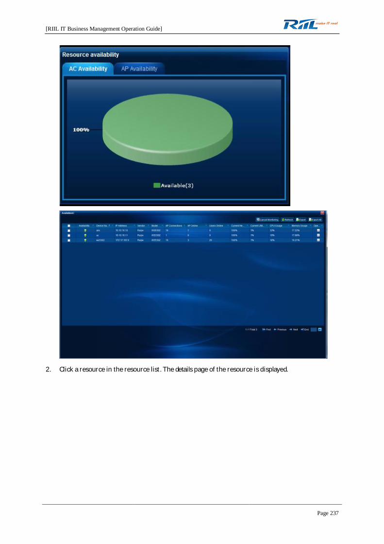
[RIIL IT Business Management Operation Guide]
Page 237
2. Click a resource in the resource list. The details page of the resource is displayed.
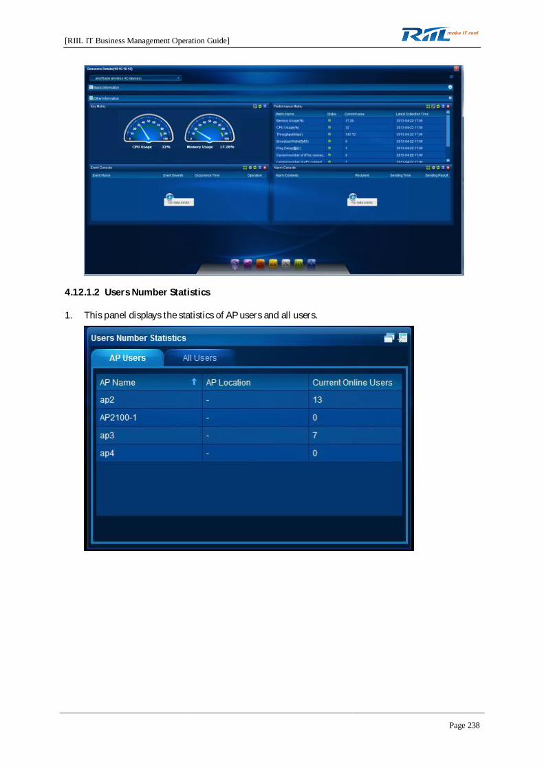
[RIIL IT Business Management Operation Guide]
Page 238
4.12.1.2 Users Number Statistics
1. This panel displays the statistics of AP users and all users.

[RIIL IT Business Management Operation Guide]
Page 239
2. On the AP Users tab page, click the view all button. The statistics of online AP users are displayed.
3. On the AP Users tab page, click the rollover button to switch to the bar chart.
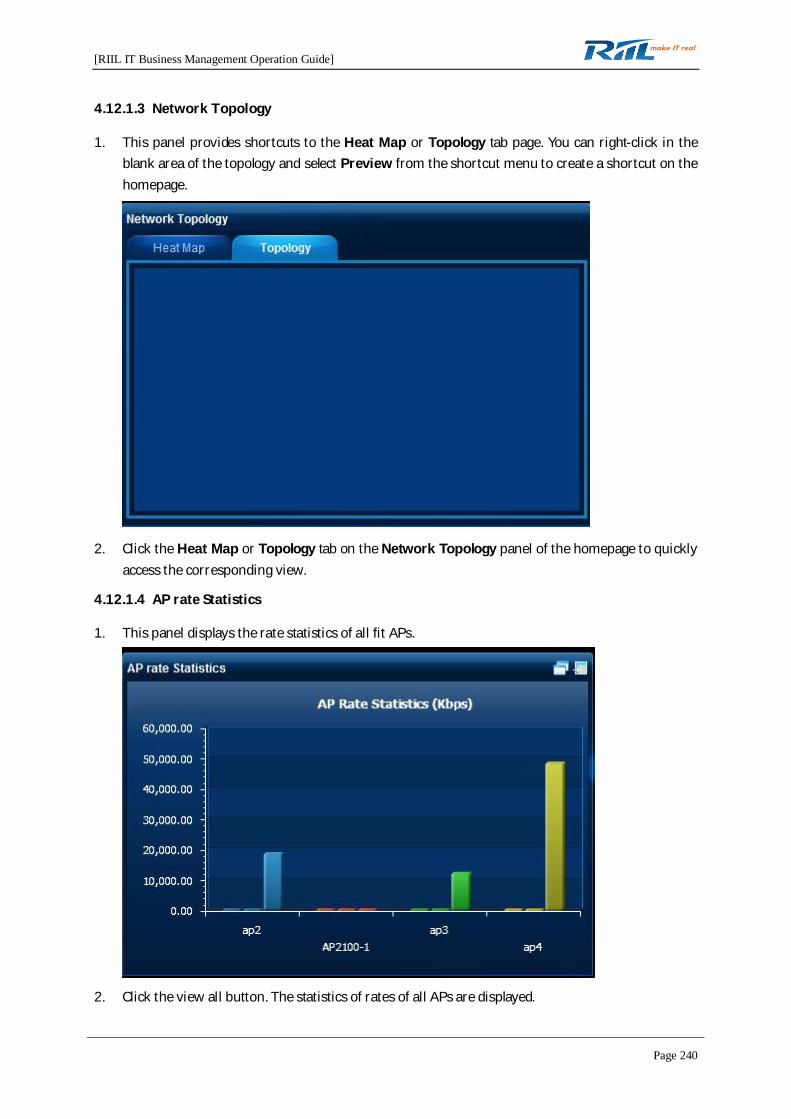
[RIIL IT Business Management Operation Guide]
Page 240
4.12.1.3 Network Topology
1. This panel provides shortcuts to the Heat Map or Topology tab page. You can right-click in theblank area of the topology and select Preview from the shortcut menu to create a shortcut on thehomepage.
2. Click the Heat Map or Topology tab on the Network Topology panel of the homepage to quicklyaccess the corresponding view.
4.12.1.4 AP rate Statistics
1. This panel displays the rate statistics of all fit APs.
2. Click the view all button. The statistics of rates of all APs are displayed.

[RIIL IT Business Management Operation Guide]
Page 241
3. Click the rollover button to switch to the table.
4.12.1.5 AP out-of-service rate
1. This panel displays the out-of-service rate statistics of all fit APs.

[RIIL IT Business Management Operation Guide]
Page 242
2. Click the view all button. The out-of-service rate statistics of all APs are displayed.
3. Click the rollover button to switch to the table.

[RIIL IT Business Management Operation Guide]
Page 243
4.12.1.6 Event Statistics
1. This panel displays event statistics by event severity.
2. Click the pie chart to display the event list.

[RIIL IT Business Management Operation Guide]
Page 244
4.12.2 Wireless Topology
The wireless topology module provides two functions: heat map and geographic location topology. Touse the functions, you need to discover and monitor ACs in the system, and then allocate geographiclocations for fit APs in Wireless Configuration > Hotspot Configuration.
4.12.2.1 Heat Map
If a heat map is created, the heat map is automatically displayed after you access the WirelessTopology page.
The heat map visually displays the AP signal coverage in the graphic form.
1. Click the add button on the right Wireless Heat Map panel to create a heat map.
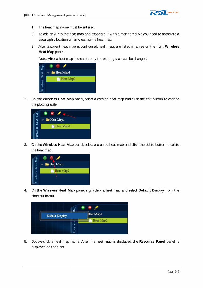
[RIIL IT Business Management Operation Guide]
Page 245
1) The heat map name must be entered.
2) To add an AP to the heat map and associate it with a monitored AP, you need to associate ageographic location when creating the heat map.
3) After a parent heat map is configured, heat maps are listed in a tree on the right WirelessHeat Map panel.
Note: After a heat map is created, only the plotting scale can be changed.
2. On the Wireless Heat Map panel, select a created heat map and click the edit button to changethe plotting scale.
3. On the Wireless Heat Map panel, select a created heat map and click the delete button to deletethe heat map.
4. On the Wireless Heat Map panel, right-click a heat map and select Default Display from theshortcut menu.
5. Double-click a heat map name. After the heat map is displayed, the Resource Panel panel isdisplayed on the right.
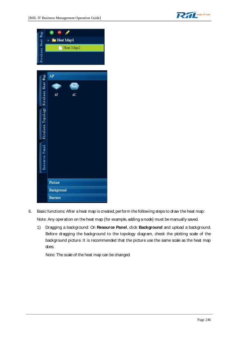
[RIIL IT Business Management Operation Guide]
Page 246
6. Basic functions: After a heat map is created, perform the following steps to draw the heat map:
Note: Any operation on the heat map (for example, adding a node) must be manually saved.
1) Dragging a background: On Resource Panel, click Background and upload a background.Before dragging the background to the topology diagram, check the plotting scale of thebackground picture. It is recommended that the picture use the same scale as the heat mapdoes.
Note: The scale of the heat map can be changed.

[RIIL IT Business Management Operation Guide]
Page 247
2) Dragging an AP: On Resource Panel, drag an AP from the Device area to the topology. Afterthe AP is dragged to the topology, the New page is displayed, where you can configure the APassociated with the node. The AP that can be associated is an AP allocated for the geographiclocation associated with the current heat map.
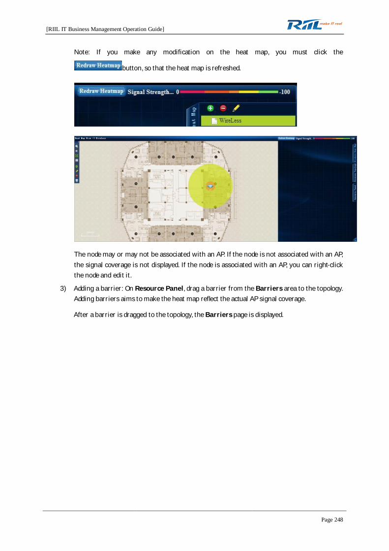
[RIIL IT Business Management Operation Guide]
Page 248
Note: If you make any modification on the heat map, you must click the
button, so that the heat map is refreshed.
The node may or may not be associated with an AP. If the node is not associated with an AP,the signal coverage is not displayed. If the node is associated with an AP, you can right-clickthe node and edit it.
3) Adding a barrier: On Resource Panel, drag a barrier from the Barriers area to the topology.Adding barriers aims to make the heat map reflect the actual AP signal coverage.
After a barrier is dragged to the topology, the Barriers page is displayed.
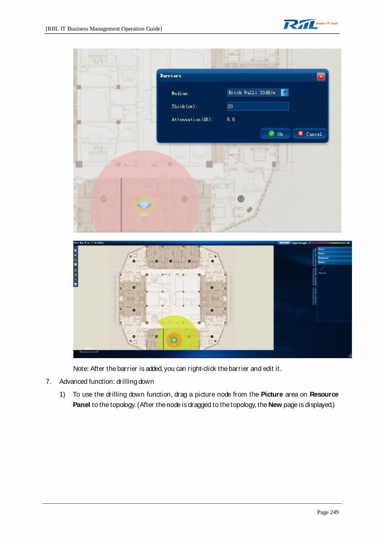
[RIIL IT Business Management Operation Guide]
Page 249
Note: After the barrier is added, you can right-click the barrier and edit it.
7. Advanced function: drilling down
1) To use the drilling down function, drag a picture node from the Picture area on ResourcePanel to the topology. (After the node is dragged to the topology, the New page is displayed.)
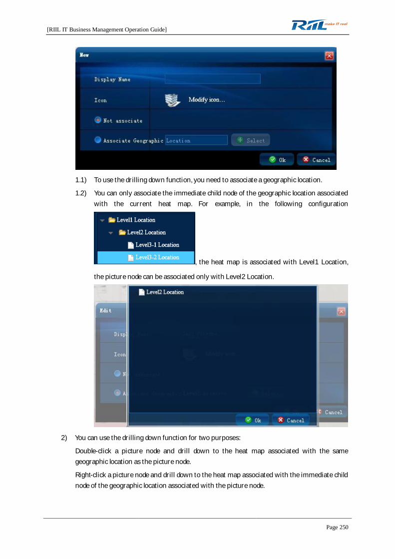
[RIIL IT Business Management Operation Guide]
Page 250
1.1) To use the drilling down function, you need to associate a geographic location.
1.2) You can only associate the immediate child node of the geographic location associatedwith the current heat map. For example, in the following configuration
, the heat map is associated with Level1 Location,
the picture node can be associated only with Level2 Location.
2) You can use the drilling down function for two purposes:
Double-click a picture node and drill down to the heat map associated with the samegeographic location as the picture node.
Right-click a picture node and drill down to the heat map associated with the immediate childnode of the geographic location associated with the picture node.
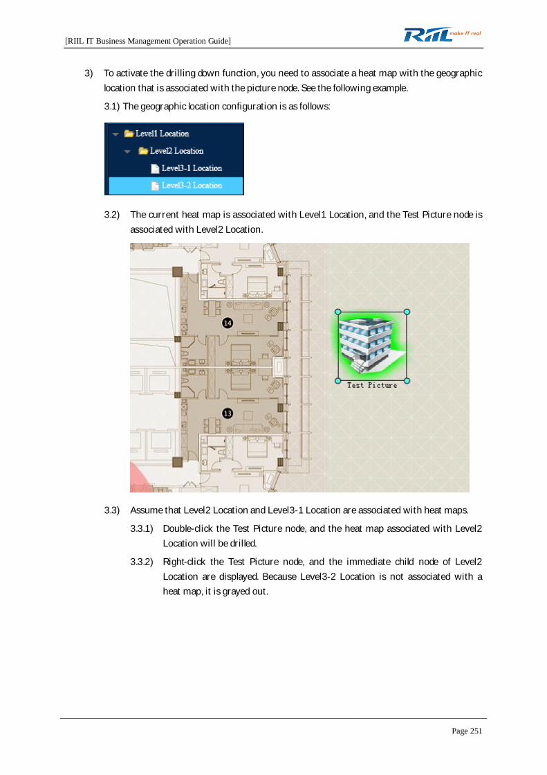
[RIIL IT Business Management Operation Guide]
Page 251
3) To activate the drilling down function, you need to associate a heat map with the geographiclocation that is associated with the picture node. See the following example.
3.1) The geographic location configuration is as follows:
3.2) The current heat map is associated with Level1 Location, and the Test Picture node isassociated with Level2 Location.
3.3) Assume that Level2 Location and Level3-1 Location are associated with heat maps.
3.3.1) Double-click the Test Picture node, and the heat map associated with Level2Location will be drilled.
3.3.2) Right-click the Test Picture node, and the immediate child node of Level2Location are displayed. Because Level3-2 Location is not associated with aheat map, it is grayed out.
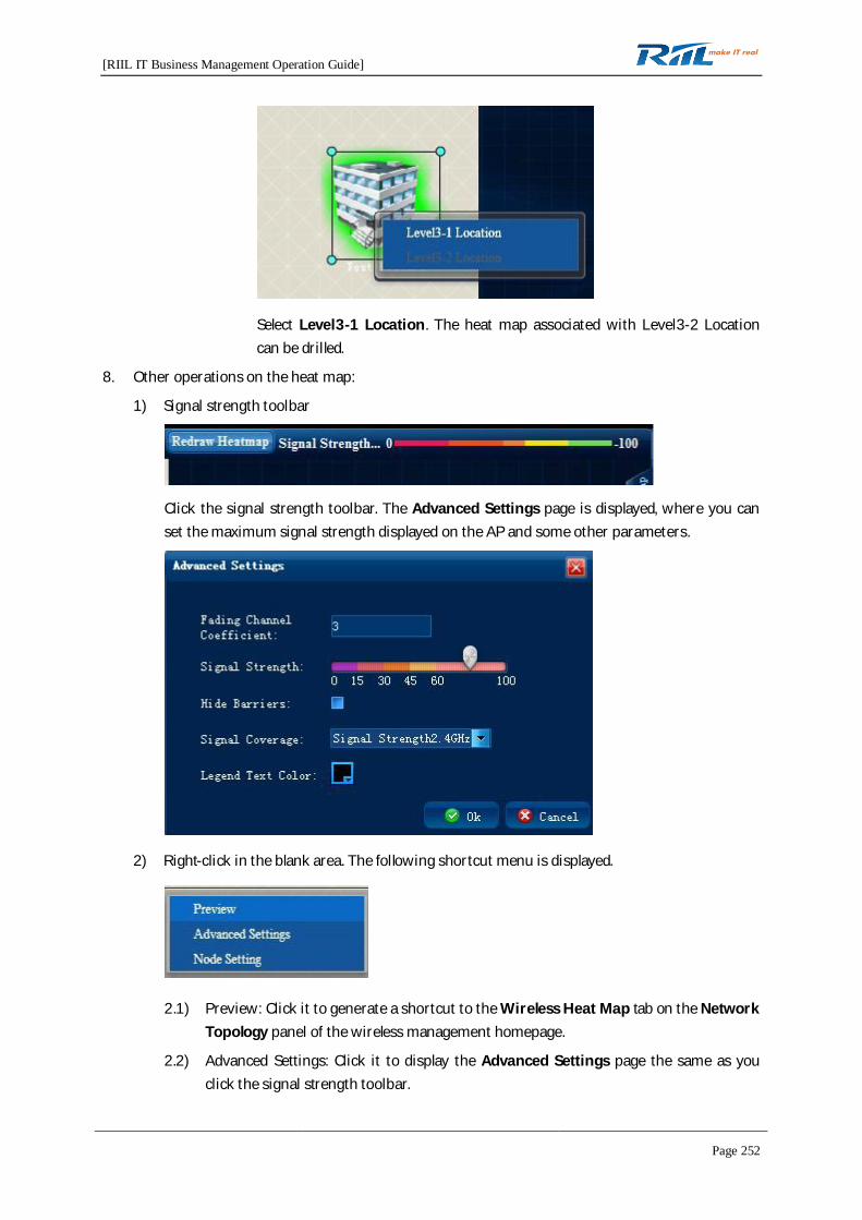
[RIIL IT Business Management Operation Guide]
Page 252
Select Level3-1 Location. The heat map associated with Level3-2 Locationcan be drilled.
8. Other operations on the heat map:
1) Signal strength toolbar
Click the signal strength toolbar. The Advanced Settings page is displayed, where you canset the maximum signal strength displayed on the AP and some other parameters.
2) Right-click in the blank area. The following shortcut menu is displayed.
2.1) Preview: Click it to generate a shortcut to the Wireless Heat Map tab on the NetworkTopology panel of the wireless management homepage.
2.2) Advanced Settings: Click it to display the Advanced Settings page the same as youclick the signal strength toolbar.

[RIIL IT Business Management Operation Guide]
Page 253
2.3 Node Setting: Click it to set node text format on the topology.
Note: Node Setting is used to set the text display effect of nodes. Legend Text Color on theAdvanced Settings page is used to set the colors of the scale and signal strength toolbar.
3) Edit button on the left toolbar
3.1) If you select a node (such as an AP node or a barrier) and click the Edit button, a pagefor editing the node is displayed. If you click the Edit button without selecting any node,the Advanced Settings page is displayed, which is the same as that displayed whenyou click the signal strength toolbar.
4.12.2.2 Geographic Location Topology
If no heat map is configured, the Wireless Topology page is displayed. The topology of the first node(not the All node) in the geographic location tree in Hotspot Configuration.
1. The topology includes all fit APs configured under the node and the ACs of the fit APs.
2. Click any other node on the Wireless Topology panel. The corresponding topology will bedisplayed.
3. When the geographic location topology is displayed, the right panel does not display the ResourcePanel tab.
4. Right-click in the blank area. The following shortcut menu is displayed.

[RIIL IT Business Management Operation Guide]
Page 254
1) Export: Click it to export a screenshot of the current topology.
2) Preview: Click it to generate a shortcut to the Topology tab on the Network Topology panelon the wireless management homepage
3) Reset Layout: Click it to apply the star layout
4) Display/Does not Display Hidden Node: Click it to display or not display hidden nodes.
5) View the List of Hidden Resources: Click to view the list of hidden resources and change thehidden state of the resources
6) Device Mark: Click it to specify the IP address or resource name to be displayed for a deviceon the topology
7) Node Setting: Click it to set node text format on the topology
5. Right-click an AC. The following shortcut menu is displayed.
1) Display/Hide node: Click it to display or hide nodes.
2) Business Structure Chart: Click it to view resource locations in the business structure chart.
3) Detailed Information: Click it to display the Resource Details page.
4) Event Details: Click to display the Event Details page.
5) Common Tools
6) Information Table: Click it to view the AC interface table and routing table
6. Right-click an AP. The following shortcut menu is displayed.
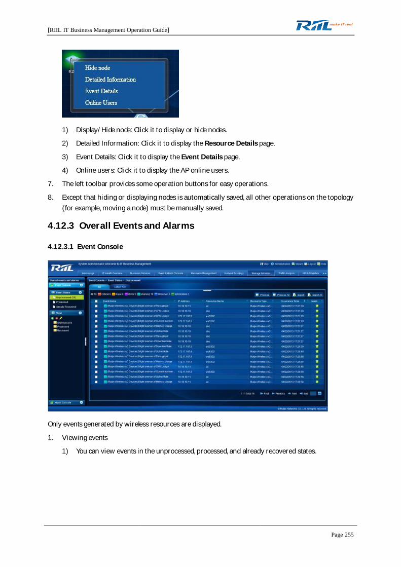
[RIIL IT Business Management Operation Guide]
Page 255
1) Display/Hide node: Click it to display or hide nodes.
2) Detailed Information: Click it to display the Resource Details page.
3) Event Details: Click it to display the Event Details page.
4) Online users: Click it to display the AP online users.
7. The left toolbar provides some operation buttons for easy operations.
8. Except that hiding or displaying nodes is automatically saved, all other operations on the topology(for example, moving a node) must be manually saved.
4.12.3 Overall Events and Alarms
4.12.3.1 Event Console
Only events generated by wireless resources are displayed.
1. Viewing events
1) You can view events in the unprocessed, processed, and already recovered states.
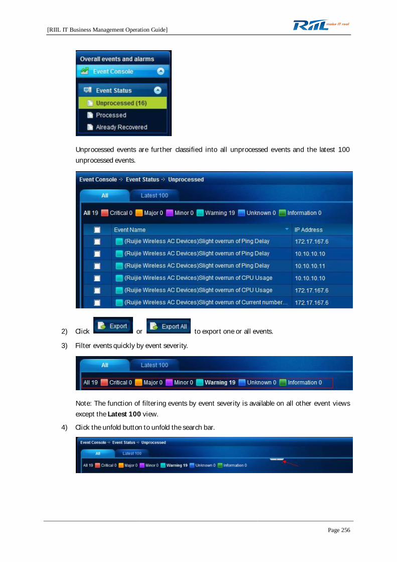
[RIIL IT Business Management Operation Guide]
Page 256
Unprocessed events are further classified into all unprocessed events and the latest 100unprocessed events.
2) Click or to export one or all events.
3) Filter events quickly by event severity.
Note: The function of filtering events by event severity is available on all other event viewsexcept the Latest 100 view.
4) Click the unfold button to unfold the search bar.

[RIIL IT Business Management Operation Guide]
Page 257
Note: This function is available on all other event views except the Latest 100 view.
2. Processing events
1) Unprocessed events can be manually processed. The processed events no longer displayedfor the resource node on the wireless topology.
2) You can click or to process one or all events in the
unprocessed event list.
3. Defining a view
1) You can define an event view for your concerned events. In the self-defined view, events arealso classified into unprocessed, processed and recovered events.
2) are used to create, delete, or edit a view.
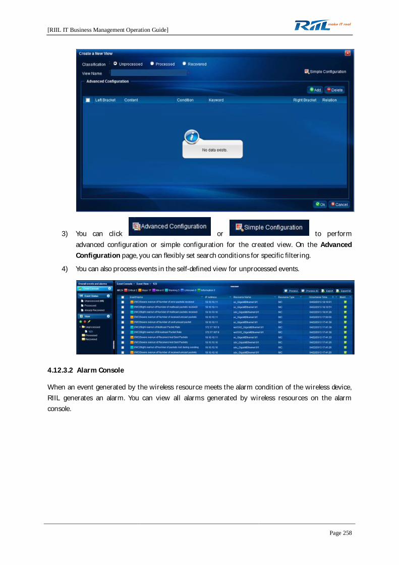
[RIIL IT Business Management Operation Guide]
Page 258
3) You can click or to performadvanced configuration or simple configuration for the created view. On the AdvancedConfiguration page, you can flexibly set search conditions for specific filtering.
4) You can also process events in the self-defined view for unprocessed events.
4.12.3.2 Alarm Console
When an event generated by the wireless resource meets the alarm condition of the wireless device,RIIL generates an alarm. You can view all alarms generated by wireless resources on the alarmconsole.
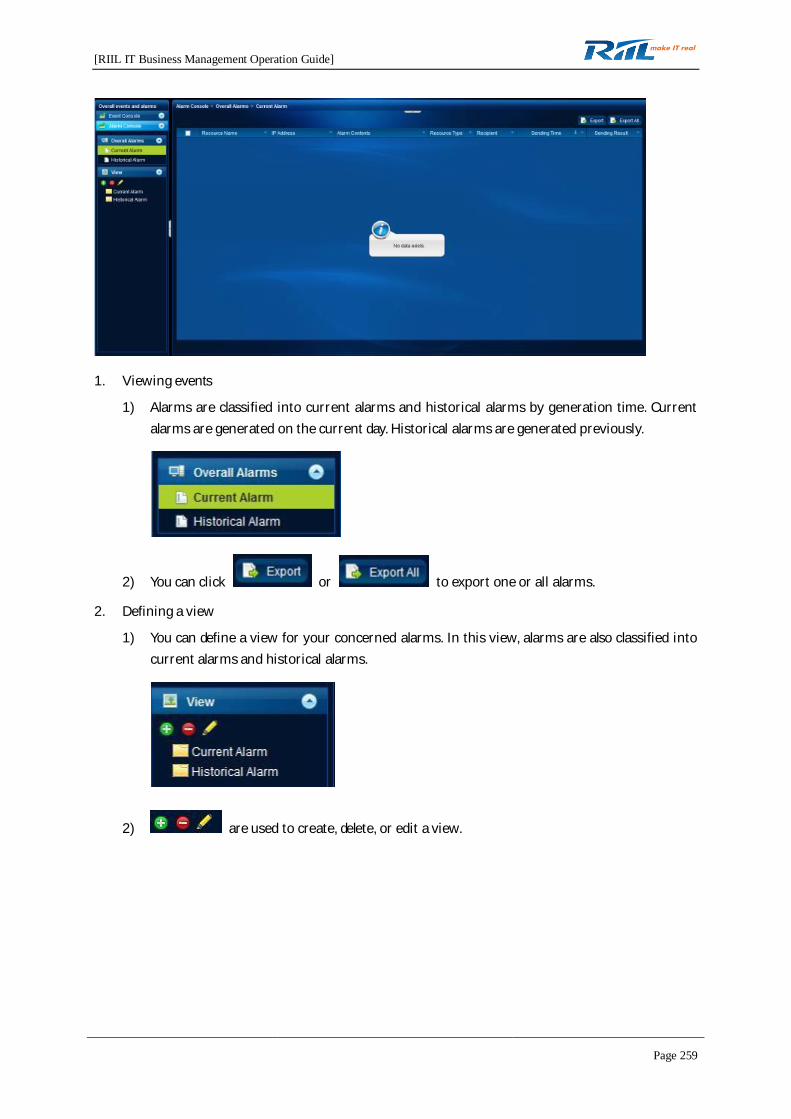
[RIIL IT Business Management Operation Guide]
Page 259
1. Viewing events
1) Alarms are classified into current alarms and historical alarms by generation time. Currentalarms are generated on the current day. Historical alarms are generated previously.
2) You can click or to export one or all alarms.
2. Defining a view
1) You can define a view for your concerned alarms. In this view, alarms are also classified intocurrent alarms and historical alarms.
2) are used to create, delete, or edit a view.

[RIIL IT Business Management Operation Guide]
Page 260
3) You can click or to performadvanced configuration or simple configuration for the created view. In the AdvancedConfiguration area, you can flexibly set search conditions for specific filtering.
4.12.4 Wireless Resource Management
On the Wireless Resource Management page, you can view information of the monitored AC, fat AP,fit AP, and WLAN resources, number of online users, and details of out-of-service fit APs, and managethe access ports of fit APs.
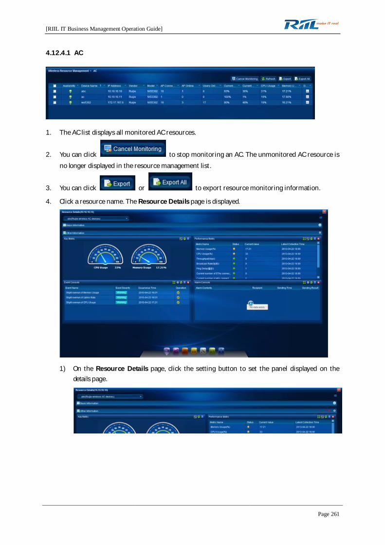
[RIIL IT Business Management Operation Guide]
Page 261
4.12.4.1 AC
1. The AC list displays all monitored AC resources.
2. You can click to stop monitoring an AC. The unmonitored AC resource isno longer displayed in the resource management list.
3. You can click or to export resource monitoring information.
4. Click a resource name. The Resource Details page is displayed.
1) On the Resource Details page, click the setting button to set the panel displayed on thedetails page.
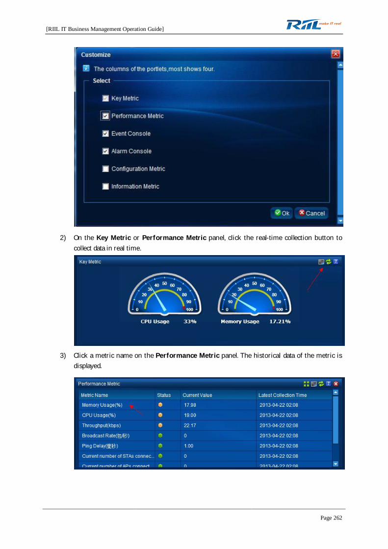
[RIIL IT Business Management Operation Guide]
Page 262
2) On the Key Metric or Performance Metric panel, click the real-time collection button tocollect data in real time.
3) Click a metric name on the Performance Metric panel. The historical data of the metric isdisplayed.

[RIIL IT Business Management Operation Guide]
Page 263
4) Click the drop-down list in the upper left corner of the Resource Details page. Thesub-resources or associated WLANs of the AC are displayed.
5. In the resource list, you can click the button in the Operation column to view information andcomplete some operations.

[RIIL IT Business Management Operation Guide]
Page 264
4.12.4.2 Fat AP
1. The fat AP list displays all monitored fat AP resources.
2. You can click to stop monitoring a fat AP. The unmonitored fat APresource is no longer displayed in the resource management list.
3. You can click or to export resource monitoring information.
4. Click a resource name. The Resource Details page is displayed.
1) On the Resource Details page, click the setting button to set the panel displayed on thedetails page.
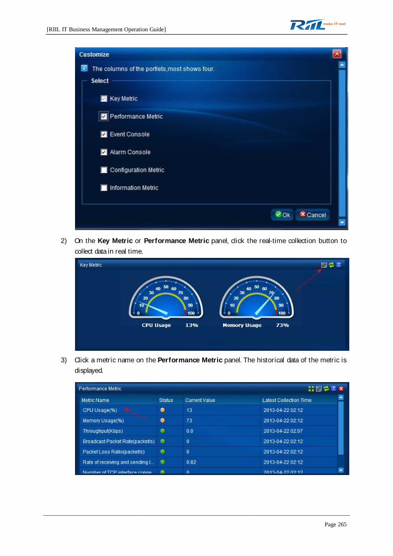
[RIIL IT Business Management Operation Guide]
Page 265
2) On the Key Metric or Performance Metric panel, click the real-time collection button tocollect data in real time.
3) Click a metric name on the Performance Metric panel. The historical data of the metric isdisplayed.

[RIIL IT Business Management Operation Guide]
Page 266
4) Click the drop-down list in the upper left corner of the Resource Details page. Thesub-resources or associated WLANs of the fat AP are displayed.
5. In the resource list, you can click the button in the Operation column to view information andcomplete some operations.
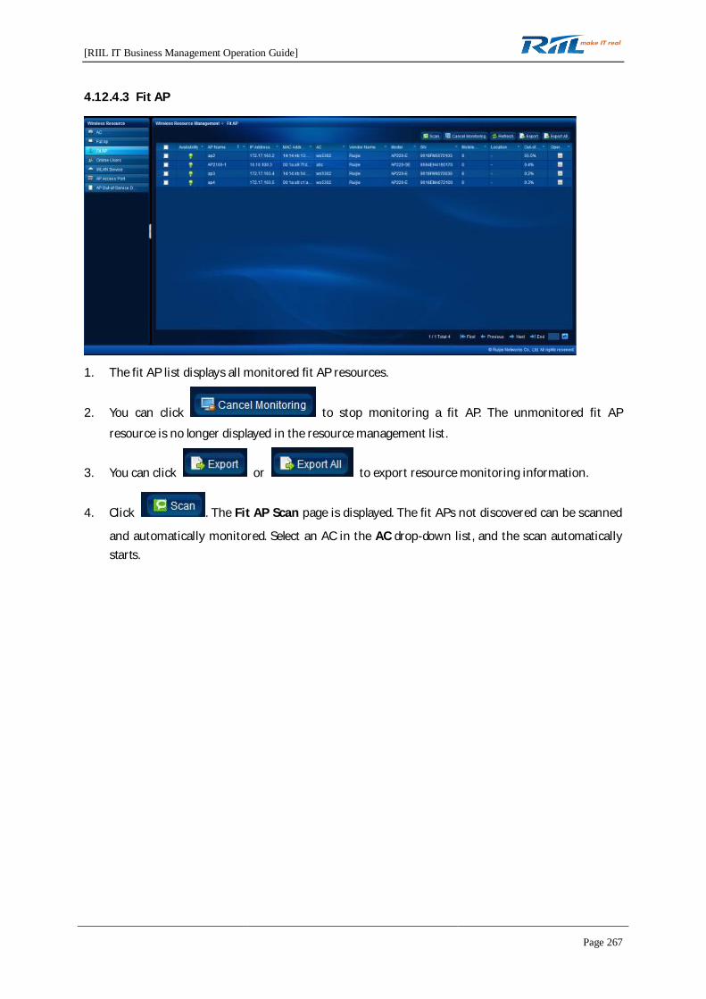
[RIIL IT Business Management Operation Guide]
Page 267
4.12.4.3 Fit AP
1. The fit AP list displays all monitored fit AP resources.
2. You can click to stop monitoring a fit AP. The unmonitored fit APresource is no longer displayed in the resource management list.
3. You can click or to export resource monitoring information.
4. Click . The Fit AP Scan page is displayed. The fit APs not discovered can be scanned
and automatically monitored. Select an AC in the AC drop-down list, and the scan automaticallystarts.
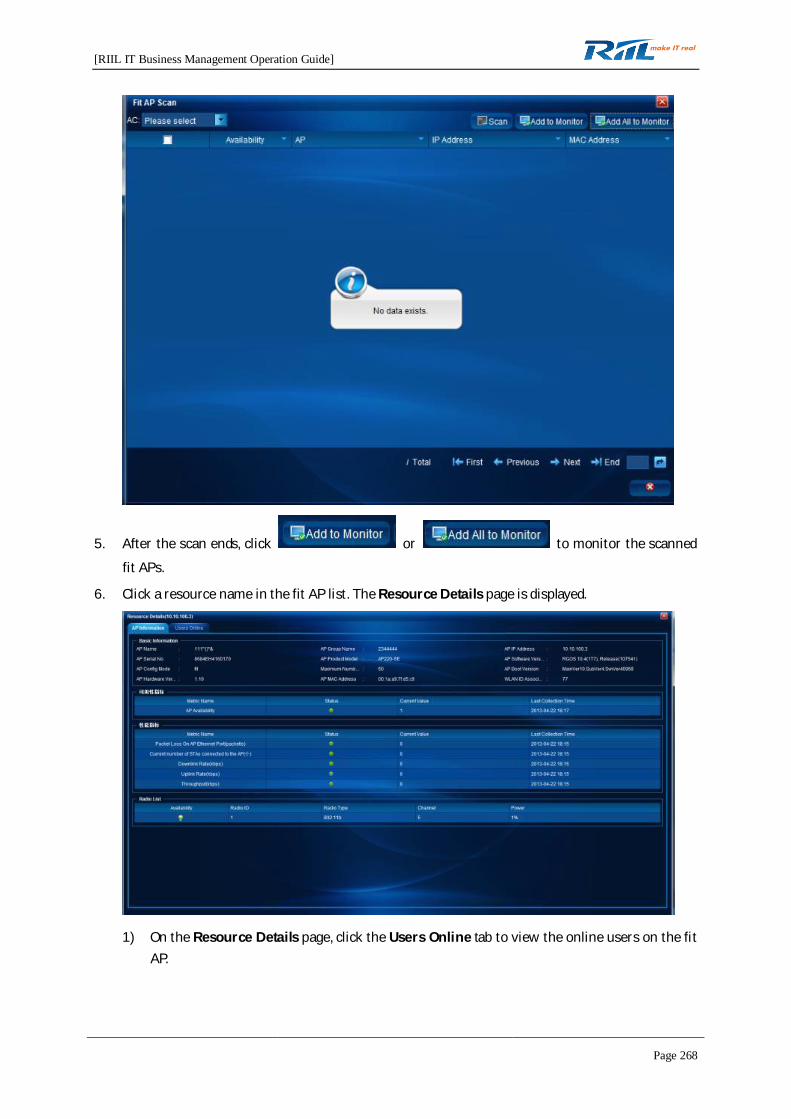
[RIIL IT Business Management Operation Guide]
Page 268
5. After the scan ends, click or to monitor the scanned
fit APs.
6. Click a resource name in the fit AP list. The Resource Details page is displayed.
1) On the Resource Details page, click the Users Online tab to view the online users on the fitAP.

[RIIL IT Business Management Operation Guide]
Page 269
2) On the AP Information tab page, click a performance metric name. The historical data of themetric is displayed.
7. Click the operation buttons in the resource list to view the unprocessed events of the fit AP.
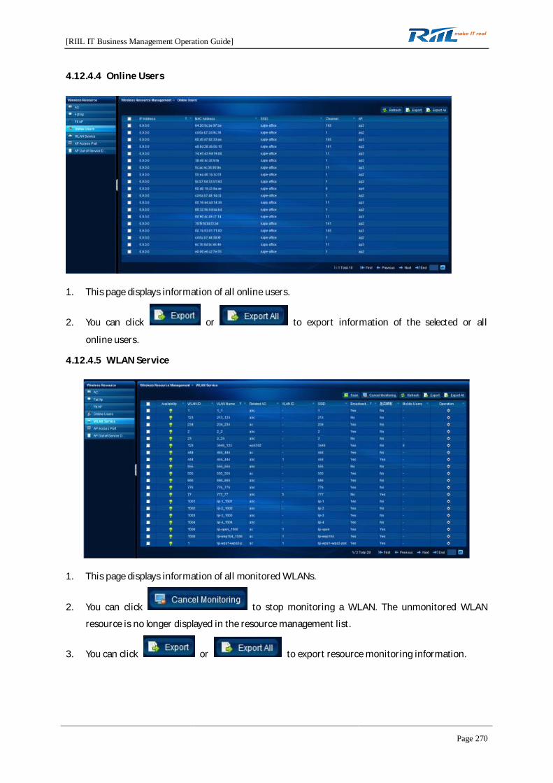
[RIIL IT Business Management Operation Guide]
Page 270
4.12.4.4 Online Users
1. This page displays information of all online users.
2. You can click or to export information of the selected or all
online users.
4.12.4.5 WLAN Service
1. This page displays information of all monitored WLANs.
2. You can click to stop monitoring a WLAN. The unmonitored WLAN
resource is no longer displayed in the resource management list.
3. You can click or to export resource monitoring information.

[RIIL IT Business Management Operation Guide]
Page 271
4. Click . The WLAN Scan page is displayed. The WLANs not discovered can be scanned
and automatically monitored. Select an AC in the AC drop-down list, and the scan automaticallystarts.
5. After the scan ends, click or to monitor the scanned
WLANs.
6. Click a resource name in the WLAN list. The WLAN Details page is displayed.
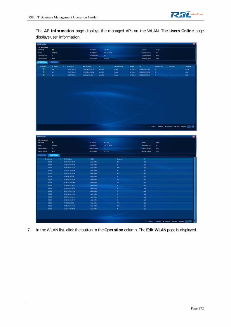
[RIIL IT Business Management Operation Guide]
Page 272
The AP Information page displays the managed APs on the WLAN. The Users Online pagedisplays user information.
7. In the WLAN list, click the button in the Operation column. The Edit WLAN page is displayed.
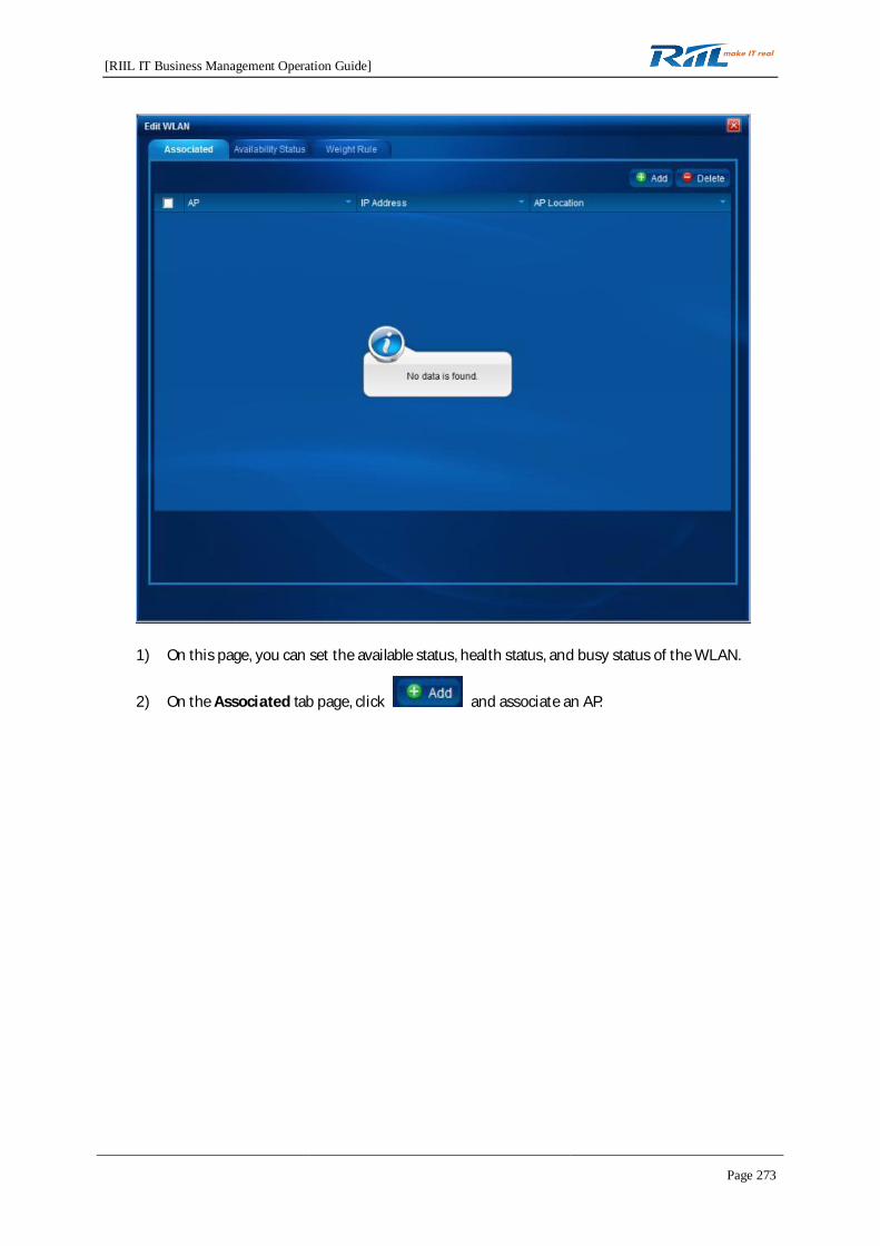
[RIIL IT Business Management Operation Guide]
Page 273
1) On this page, you can set the available status, health status, and busy status of the WLAN.
2) On the Associated tab page, click and associate an AP.
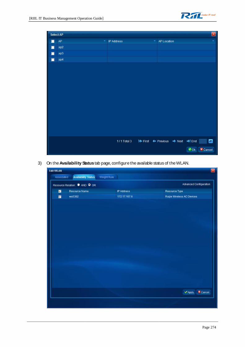
[RIIL IT Business Management Operation Guide]
Page 274
3) On the Availability Status tab page, configure the available status of the WLAN.
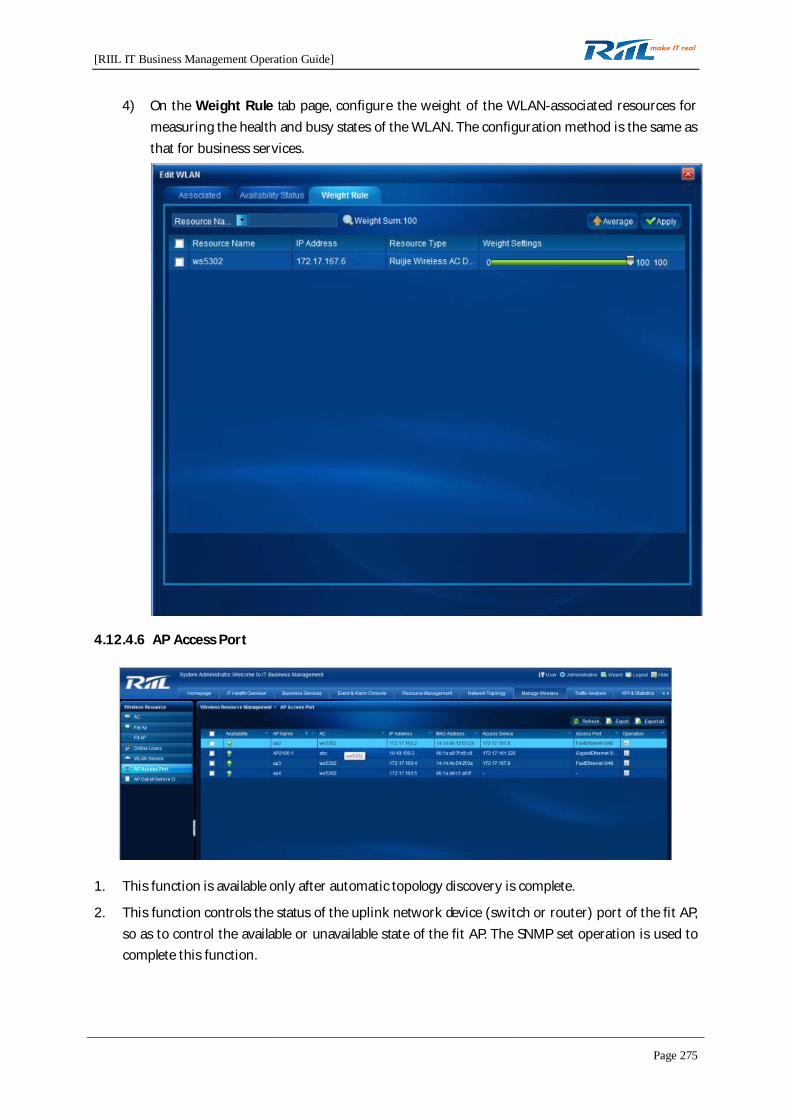
[RIIL IT Business Management Operation Guide]
Page 275
4) On the Weight Rule tab page, configure the weight of the WLAN-associated resources formeasuring the health and busy states of the WLAN. The configuration method is the same asthat for business services.
4.12.4.6 AP Access Port
1. This function is available only after automatic topology discovery is complete.
2. This function controls the status of the uplink network device (switch or router) port of the fit AP,so as to control the available or unavailable state of the fit AP. The SNMP set operation is used tocomplete this function.
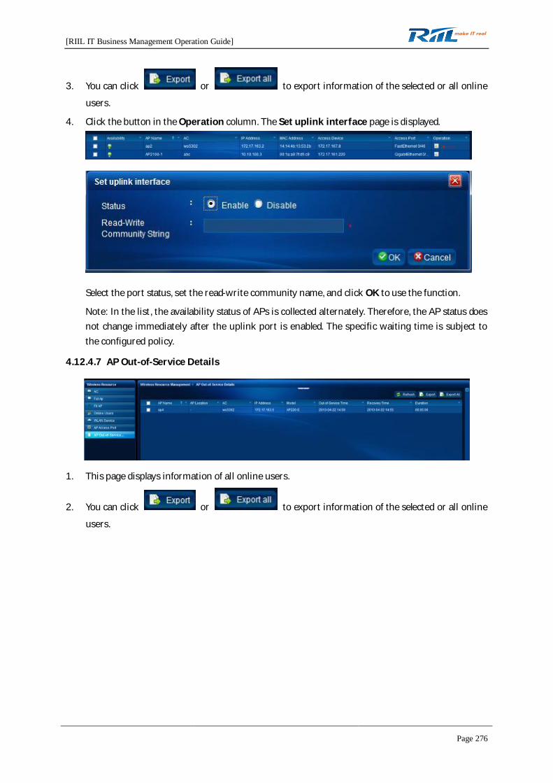
[RIIL IT Business Management Operation Guide]
Page 276
3. You can click or to export information of the selected or all online
users.
4. Click the button in the Operation column. The Set uplink interface page is displayed.
Select the port status, set the read-write community name, and click OK to use the function.
Note: In the list, the availability status of APs is collected alternately. Therefore, the AP status doesnot change immediately after the uplink port is enabled. The specific waiting time is subject tothe configured policy.
4.12.4.7 AP Out-of-Service Details
1. This page displays information of all online users.
2. You can click or to export information of the selected or all online
users.
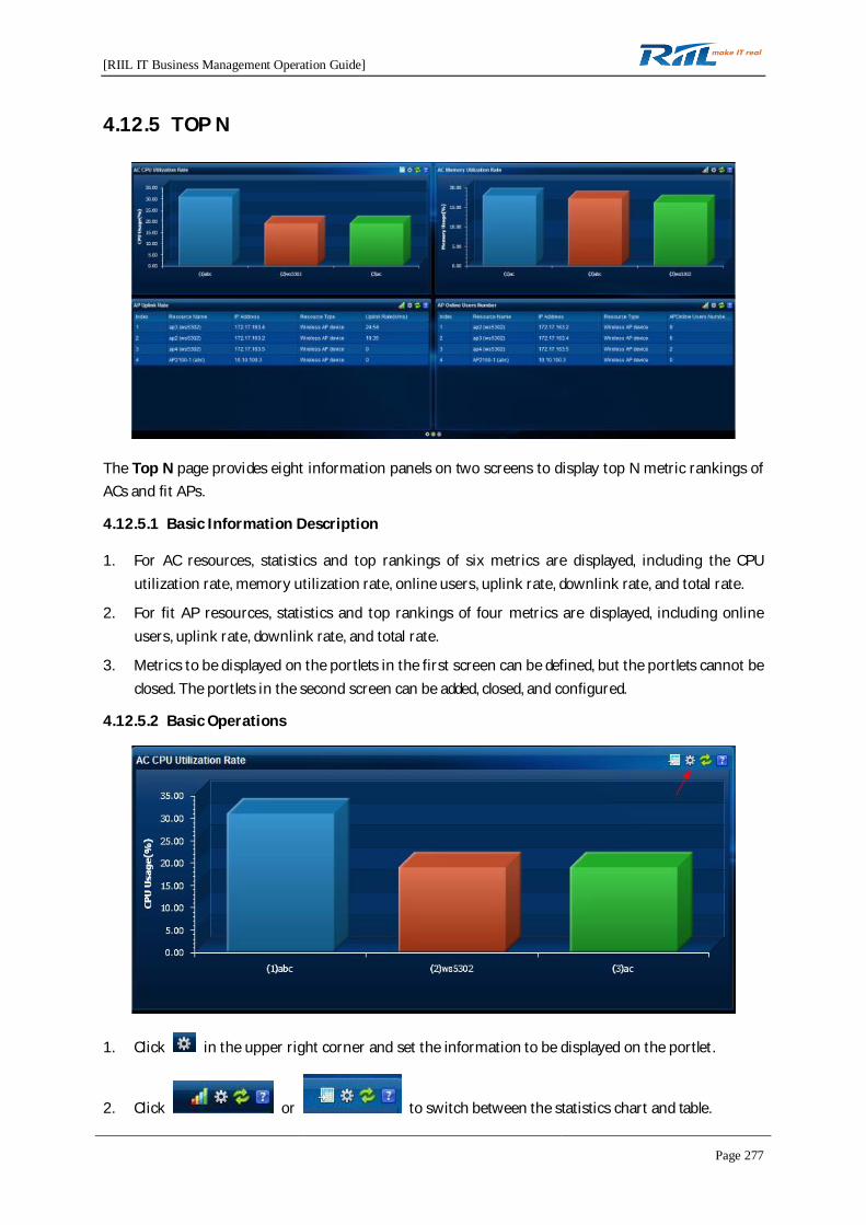
[RIIL IT Business Management Operation Guide]
Page 277
4.12.5 TOP N
The Top N page provides eight information panels on two screens to display top N metric rankings ofACs and fit APs.
4.12.5.1 Basic Information Description
1. For AC resources, statistics and top rankings of six metrics are displayed, including the CPUutilization rate, memory utilization rate, online users, uplink rate, downlink rate, and total rate.
2. For fit AP resources, statistics and top rankings of four metrics are displayed, including onlineusers, uplink rate, downlink rate, and total rate.
3. Metrics to be displayed on the portlets in the first screen can be defined, but the portlets cannot beclosed. The portlets in the second screen can be added, closed, and configured.
4.12.5.2 Basic Operations
1. Click in the upper right corner and set the information to be displayed on the portlet.
2. Click or to switch between the statistics chart and table.

[RIIL IT Business Management Operation Guide]
Page 278
3. Click the page up button.
4. In the second screen, click the plus sign on a blank portlet to configure the contents to bedisplayed on the portlet.
5. In the second screen, click to close the portlet.
6. Click a record in the statistics chart or table. The Resource Details page is displayed.
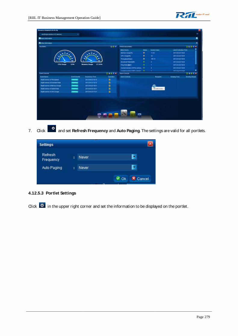
[RIIL IT Business Management Operation Guide]
Page 279
7. Click and set Refresh Frequency and Auto Paging. The settings are valid for all portlets.
4.12.5.3 Portlet Settings
Click in the upper right corner and set the information to be displayed on the portlet.
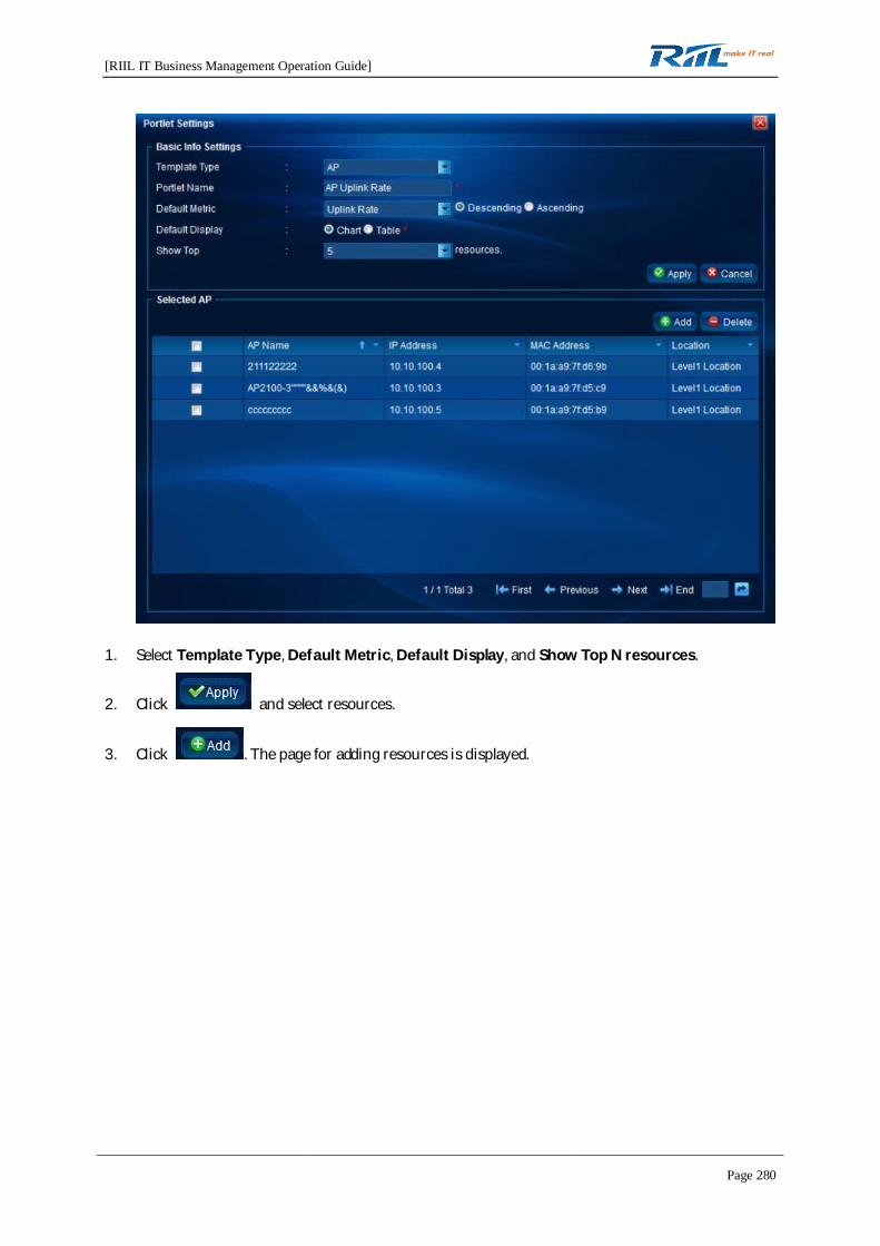
[RIIL IT Business Management Operation Guide]
Page 280
1. Select Template Type, Default Metric, Default Display, and Show Top N resources.
2. Click and select resources.
3. Click . The page for adding resources is displayed.
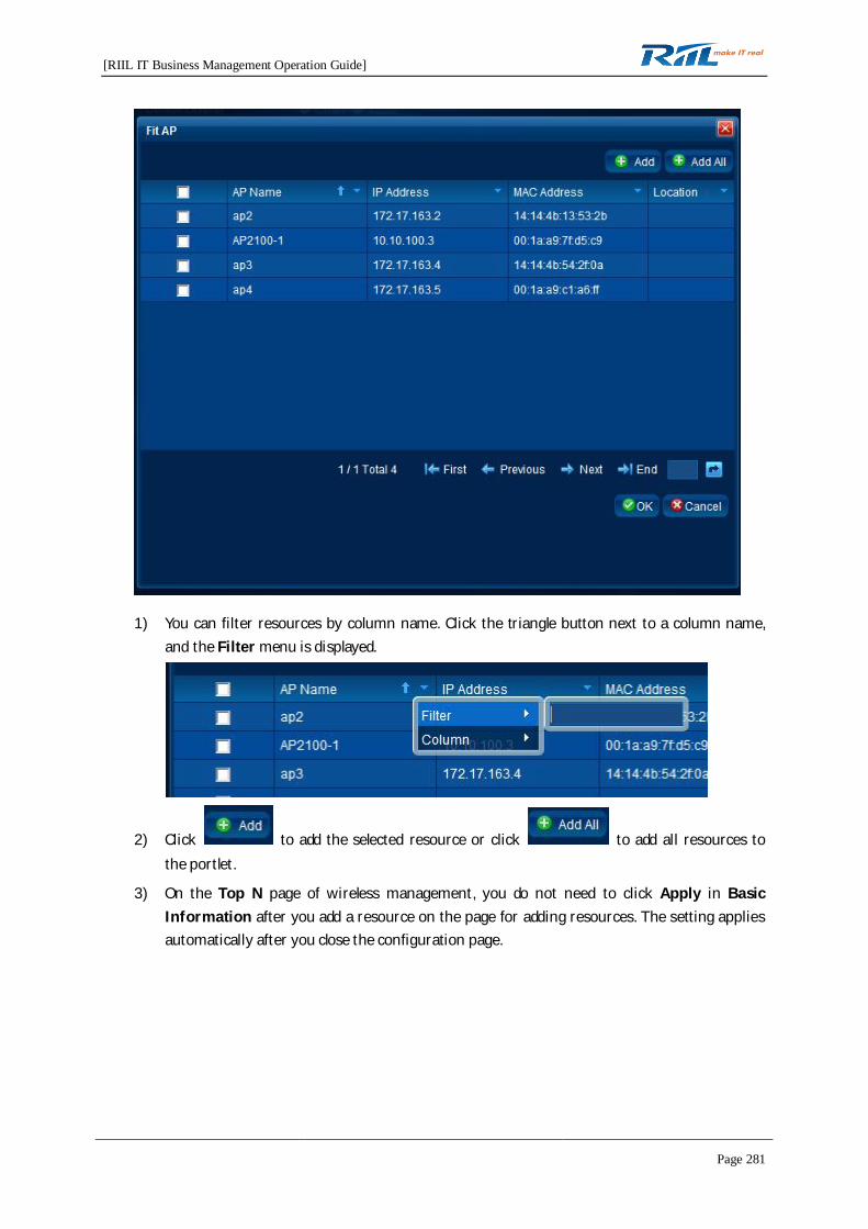
[RIIL IT Business Management Operation Guide]
Page 281
1) You can filter resources by column name. Click the triangle button next to a column name,and the Filter menu is displayed.
2) Click to add the selected resource or click to add all resources tothe portlet.
3) On the Top N page of wireless management, you do not need to click Apply in BasicInformation after you add a resource on the page for adding resources. The setting appliesautomatically after you close the configuration page.
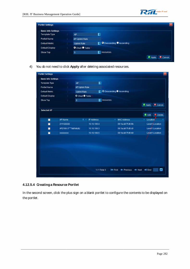
[RIIL IT Business Management Operation Guide]
Page 282
4) You do not need to click Apply after deleting associated resources.
4.12.5.4 Creating a Resource Portlet
In the second screen, click the plus sign on a blank portlet to configure the contents to be displayed onthe portlet.
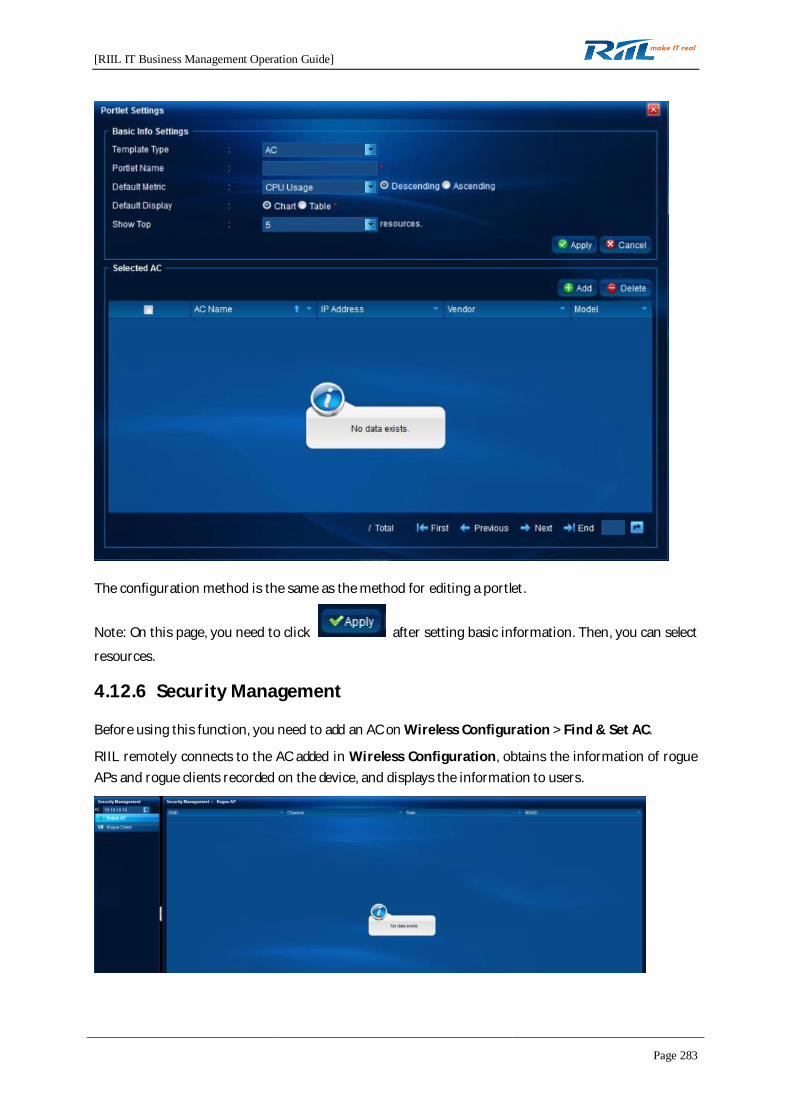
[RIIL IT Business Management Operation Guide]
Page 283
The configuration method is the same as the method for editing a portlet.
Note: On this page, you need to click after setting basic information. Then, you can select
resources.
4.12.6 Security Management
Before using this function, you need to add an AC on Wireless Configuration > Find & Set AC.
RIIL remotely connects to the AC added in Wireless Configuration, obtains the information of rogueAPs and rogue clients recorded on the device, and displays the information to users.
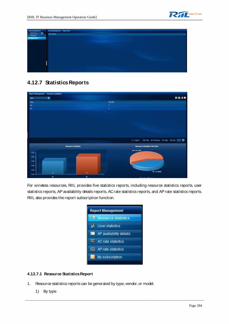
[RIIL IT Business Management Operation Guide]
Page 284
4.12.7 Statistics Reports
For wireless resources, RIIL provides five statistics reports, including resource statistics reports, userstatistics reports, AP availability details reports, AC rate statistics reports, and AP rate statistics reports.RIIL also provides the report subscription function.
4.12.7.1 Resource Statistics Report
1. Resource statistics reports can be generated by type, vendor, or model.
1) By type

[RIIL IT Business Management Operation Guide]
Page 285
2) By vendor
3) By model
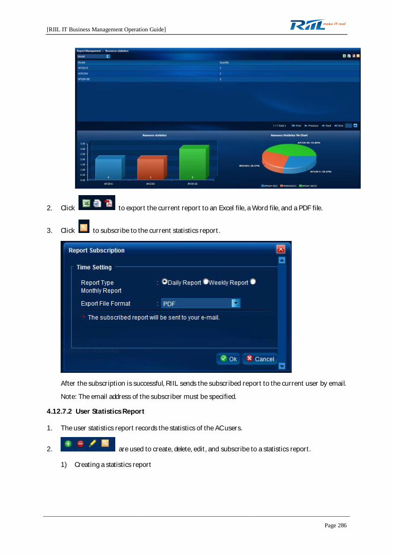
[RIIL IT Business Management Operation Guide]
Page 286
2. Click to export the current report to an Excel file, a Word file, and a PDF file.
3. Click to subscribe to the current statistics report.
After the subscription is successful, RIIL sends the subscribed report to the current user by email.
Note: The email address of the subscriber must be specified.
4.12.7.2 User Statistics Report
1. The user statistics report records the statistics of the AC users.
2. are used to create, delete, edit, and subscribe to a statistics report.
1) Creating a statistics report
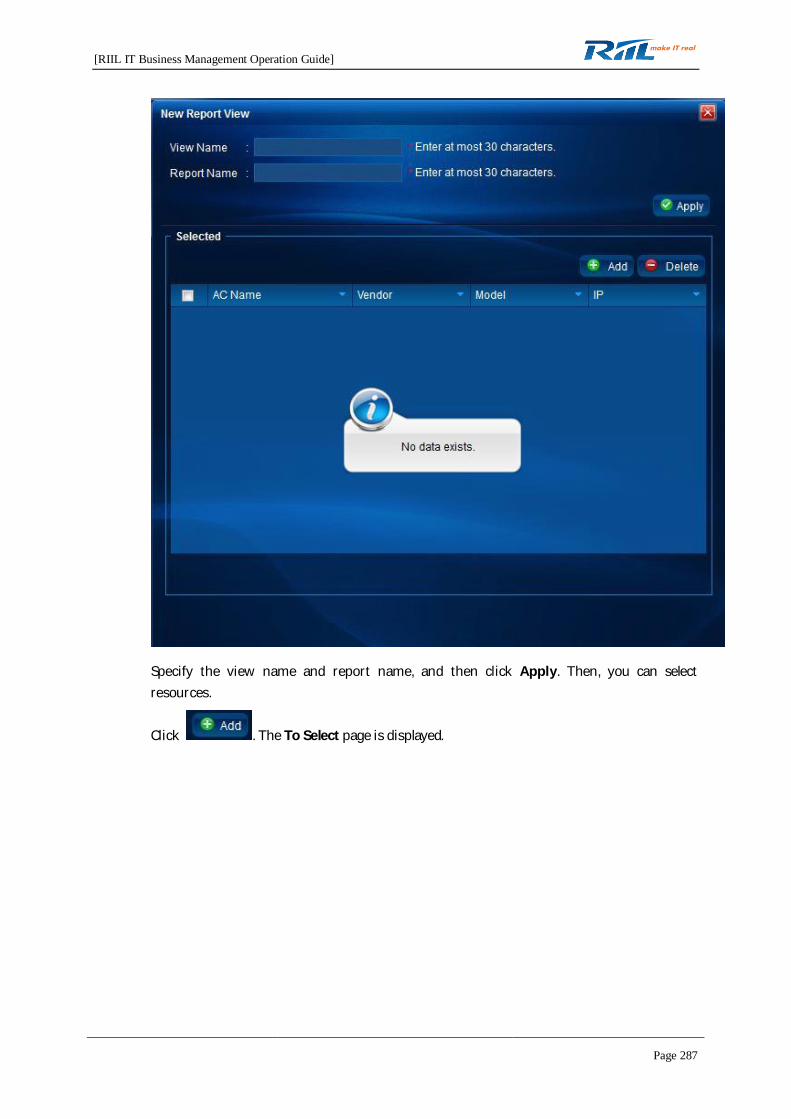
[RIIL IT Business Management Operation Guide]
Page 287
Specify the view name and report name, and then click Apply. Then, you can selectresources.
Click . The To Select page is displayed.
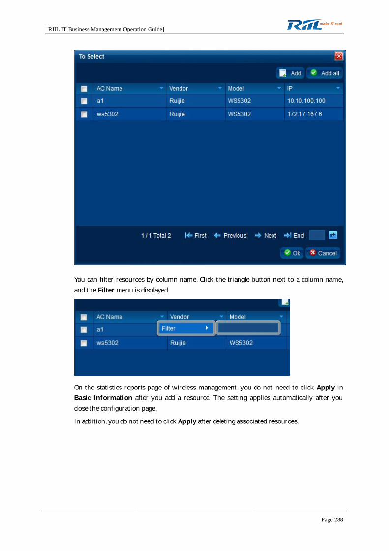
[RIIL IT Business Management Operation Guide]
Page 288
You can filter resources by column name. Click the triangle button next to a column name,and the Filter menu is displayed.
On the statistics reports page of wireless management, you do not need to click Apply inBasic Information after you add a resource. The setting applies automatically after youclose the configuration page.
In addition, you do not need to click Apply after deleting associated resources.

[RIIL IT Business Management Operation Guide]
Page 289
2) Editing a report
Select the report view and click to edit the report. The page for editing a report is the
same as the page for creating a report.
3) Deleting a report
Select the report view and click to delete the report.
Note: When a report is deleted, the subscription relationship of the report is also deleted.
4) Subscribing to a report
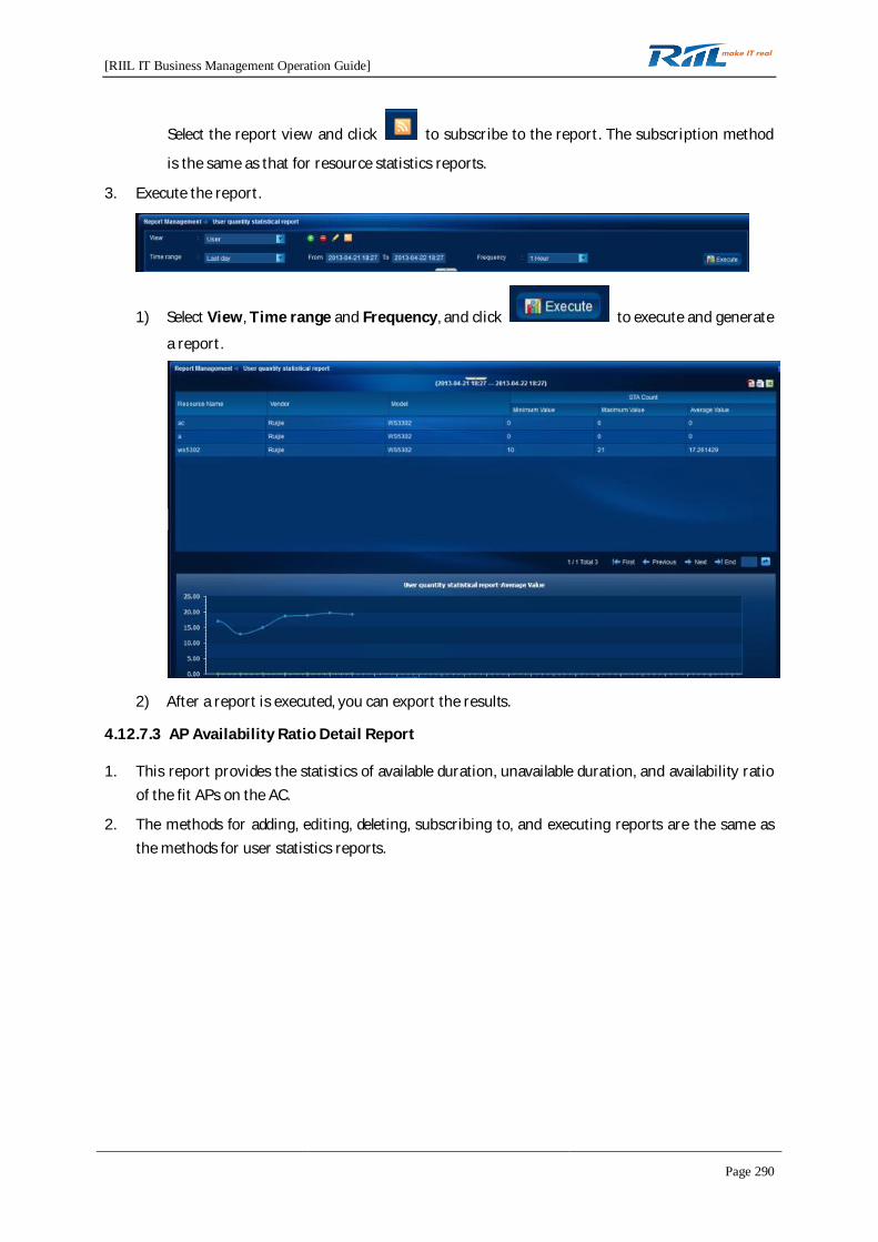
[RIIL IT Business Management Operation Guide]
Page 290
Select the report view and click to subscribe to the report. The subscription method
is the same as that for resource statistics reports.
3. Execute the report.
1) Select View, Time range and Frequency, and click to execute and generate
a report.
2) After a report is executed, you can export the results.
4.12.7.3 AP Availability Ratio Detail Report
1. This report provides the statistics of available duration, unavailable duration, and availability ratioof the fit APs on the AC.
2. The methods for adding, editing, deleting, subscribing to, and executing reports are the same asthe methods for user statistics reports.

[RIIL IT Business Management Operation Guide]
Page 291
4.12.7.4 AC Rate Statistics Report
1. This report provides statistics of AC rate.
2. The methods for adding, editing, deleting, subscribing to, and executing reports are the same asthe methods for user statistics reports.
4.12.7.5 AP Rate Statistics Report
1. This report provides statistics of AP rate.
2. The methods for adding, editing, deleting, subscribing to, and executing reports are the same asthe methods for user statistics reports.
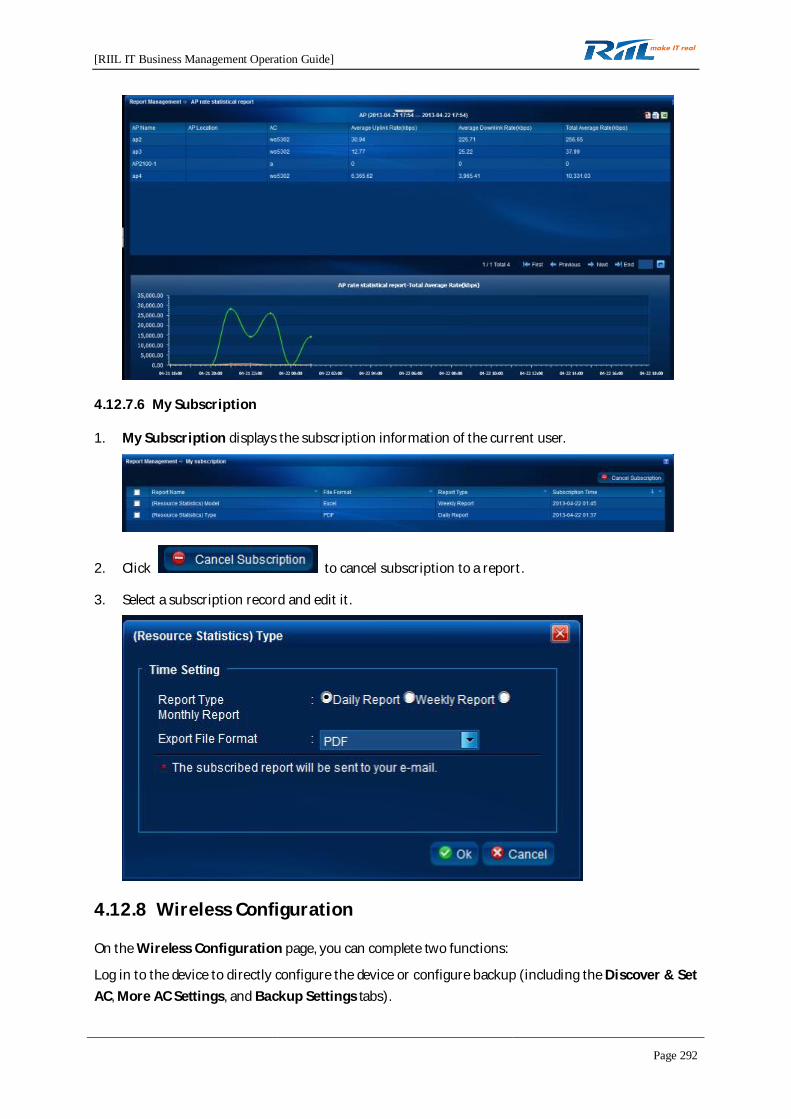
[RIIL IT Business Management Operation Guide]
Page 292
4.12.7.6 My Subscription
1. My Subscription displays the subscription information of the current user.
2. Click to cancel subscription to a report.
3. Select a subscription record and edit it.
4.12.8 Wireless Configuration
On the Wireless Configuration page, you can complete two functions:
Log in to the device to directly configure the device or configure backup (including the Discover & SetAC, More AC Settings, and Backup Settings tabs).
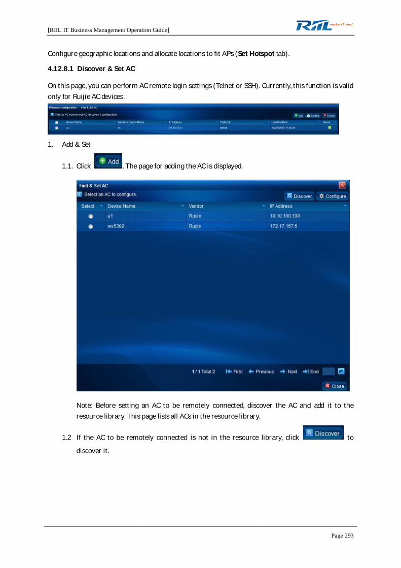
[RIIL IT Business Management Operation Guide]
Page 293
Configure geographic locations and allocate locations to fit APs (Set Hotspot tab).
4.12.8.1 Discover & Set AC
On this page, you can perform AC remote login settings (Telnet or SSH). Currently, this function is validonly for Ruijie AC devices.
1. Add & Set
1.1. Click . The page for adding the AC is displayed.
Note: Before setting an AC to be remotely connected, discover the AC and add it to theresource library. This page lists all ACs in the resource library.
1.2 If the AC to be remotely connected is not in the resource library, click to
discover it.
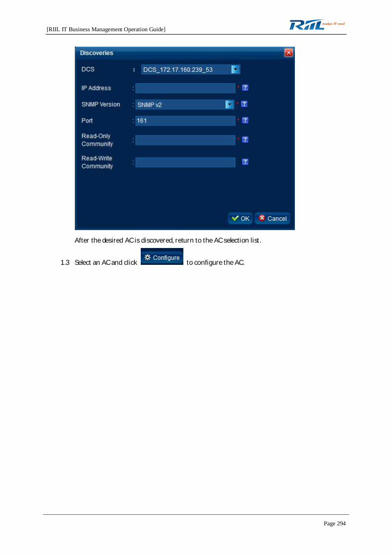
[RIIL IT Business Management Operation Guide]
Page 294
After the desired AC is discovered, return to the AC selection list.
1.3 Select an AC and click to configure the AC.
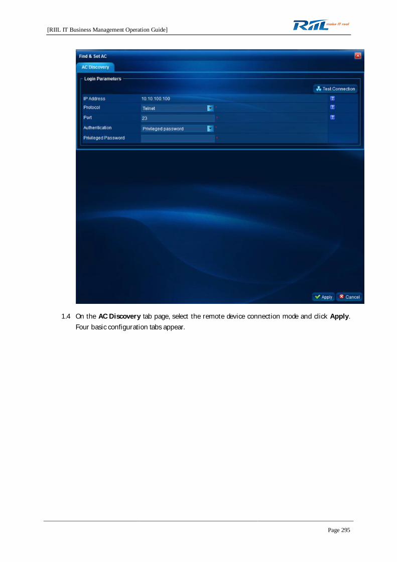
[RIIL IT Business Management Operation Guide]
Page 295
1.4 On the AC Discovery tab page, select the remote device connection mode and click Apply.Four basic configuration tabs appear.

[RIIL IT Business Management Operation Guide]
Page 296
1.5 Click the tab.
Modify the settings and click to write the settings to running-config. Click
to refresh the data on the current page.
1.6 Click the tab.
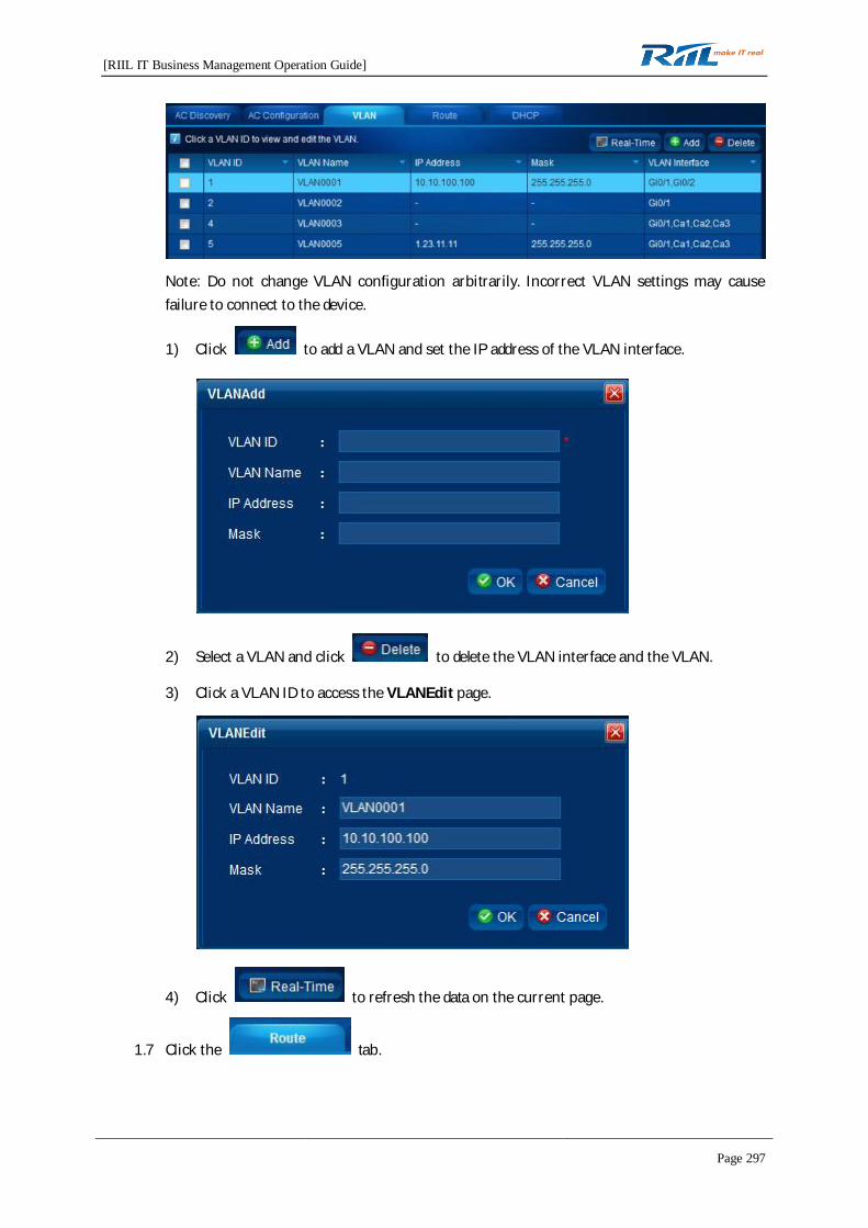
[RIIL IT Business Management Operation Guide]
Page 297
Note: Do not change VLAN configuration arbitrarily. Incorrect VLAN settings may causefailure to connect to the device.
1) Click to add a VLAN and set the IP address of the VLAN interface.
2) Select a VLAN and click to delete the VLAN interface and the VLAN.
3) Click a VLAN ID to access the VLANEdit page.
4) Click to refresh the data on the current page.
1.7 Click the tab.

[RIIL IT Business Management Operation Guide]
Page 298
Note: Do not change VLAN configuration arbitrarily. Incorrect VLAN settings may causefailure to connect to the device.
1) Click to add a route.
2) Select a route and click to delete the route.
3) Click a route record, edit the route, and then click OK. The route settings will bechanged.
4) Click to refresh the data on the current page.
1.8 Click the tab.
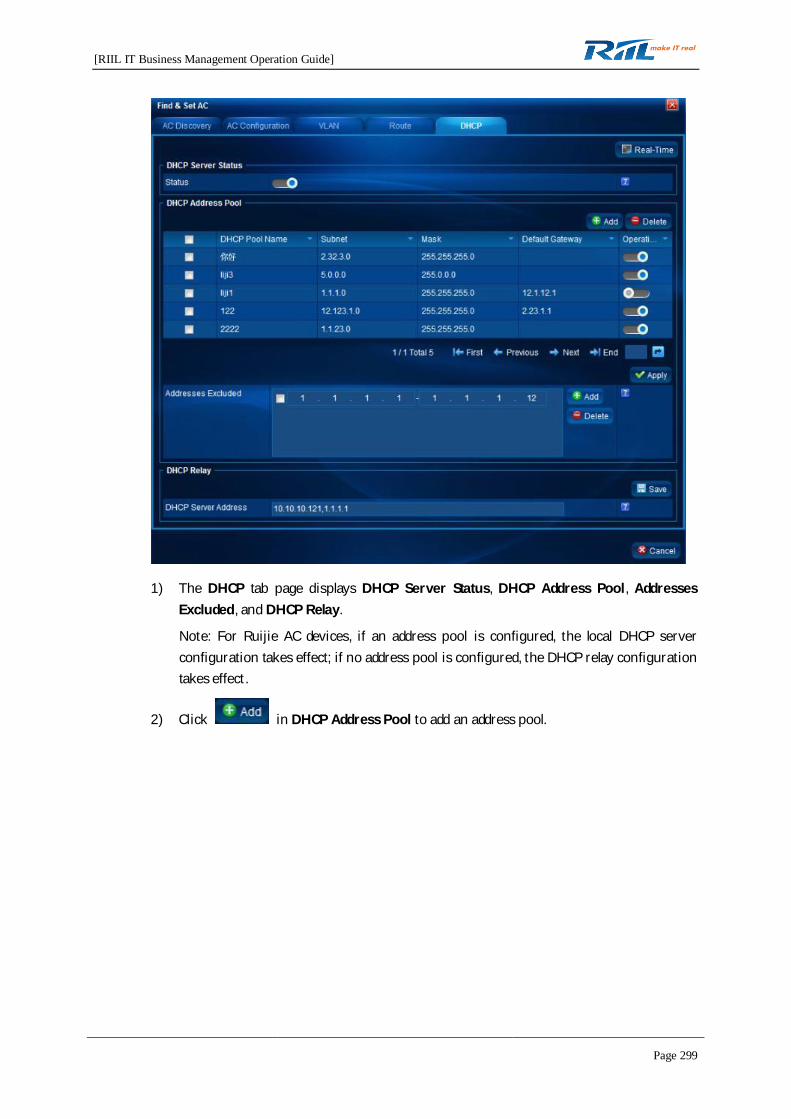
[RIIL IT Business Management Operation Guide]
Page 299
1) The DHCP tab page displays DHCP Server Status, DHCP Address Pool, AddressesExcluded, and DHCP Relay.
Note: For Ruijie AC devices, if an address pool is configured, the local DHCP serverconfiguration takes effect; if no address pool is configured, the DHCP relay configurationtakes effect.
2) Click in DHCP Address Pool to add an address pool.

[RIIL IT Business Management Operation Guide]
Page 300
3) On the DHCP tab page, you need to click for the settings to take effect after
adding, deleting, or modifying the excluded addresses.
4) Multiple DHCP relay servers can be configured. Use a comma (,) to separate the servers
in between. After configuring the DHCP relay servers, click for the
configuration to take effect.
5) Click to refresh the data on the current page.

[RIIL IT Business Management Operation Guide]
Page 301
1.9 In the Find & Set AC list, click a device for which an AC is added. The edit details page isdisplayed.
2. Writing into startup-config
Note: The settings on the Find & Set AC page and the More AC Settings page are only written torunning-config of the device. To save the settings permanently, you need to write the settings tostartup-config.
In the Find & Set AC list, click the button on the Operation column to write running-config intostartup-config.
3. Backup
In the Find & Set AC list, select an AC and click to back up the device settings. You
can download the backup configuration files on the Backup Settings page.
4.12.8.2 More AC Settings
You can perform more AC settings on the More AC Settings page.
1. In the toolbar on the left, select the IP address of an AC, and then select a menu to access thecorresponding page for configuration.
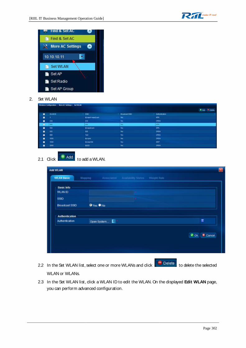
[RIIL IT Business Management Operation Guide]
Page 302
2. Set WLAN
2.1 Click to add a WLAN.
2.2 In the Set WLAN list, select one or more WLANs and click to delete the selected
WLAN or WLANs.
2.3 In the Set WLAN list, click a WLAN ID to edit the WLAN. On the displayed Edit WLAN page,you can perform advanced configuration.

[RIIL IT Business Management Operation Guide]
Page 303
2.4 Click . The Mapping tab page is displayed, where you can set mapping
VLANs and AP groups for the WLAN.
Click to add mapping or to delete mapping.
2.5 Click the , , and tab to set the
availability status, health status, and busy status of the WLAN.
Note: The configurations completed on these three tab pages are monitored by RIIL and notconfigured on the device. The configurations are the same as those in Wireless ResourceManagement > WLAN Service.
3. Set AP
3.1 Select an unavailable AP and click to delete it.
3.2 Click the name of an available AP to set the AP.

[RIIL IT Business Management Operation Guide]
Page 304
3.3 Click to obtain the AP configuration on the device in real time.
4. Set Radio
4.1 Select a radio in the list and click or to enable or disable the
radio.
4.2 Click the operation button in the Operation column to enable or disable one radio.
4.3 Click a radio ID to edit the radio.
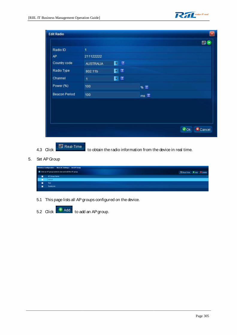
[RIIL IT Business Management Operation Guide]
Page 305
4.3 Click to obtain the radio information from the device in real time.
5. Set AP Group
5.1 This page lists all AP groups configured on the device.
5.2 Click to add an AP group.

[RIIL IT Business Management Operation Guide]
Page 306
1) Enter the AP group name and click to create an AP group on the device.
2) Add APs to the AP group.
3) Click the tab and configure the WLAN, VLAN, and radio mapping.
5.3 Click an AP group name. The Edit AP Group page is displayed. Then, you can add APs andassociations to the AP group.
5.4 Select an AP group and click to delete the AP group.
5.5 Click to obtain the AP groups in real time.
6. Set Mobility
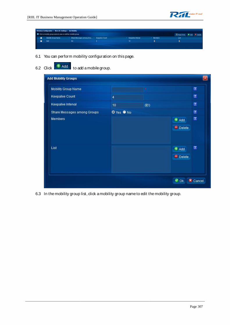
[RIIL IT Business Management Operation Guide]
Page 307
6.1 You can perform mobility configuration on this page.
6.2 Click to add a mobile group.
6.3 In the mobility group list, click a mobility group name to edit the mobility group.

[RIIL IT Business Management Operation Guide]
Page 308
6.4 Select a mobility group and click to delete the mobility group.
6.5 Click to obtain the mobility groups in real time.
6.6 Click the Member column or to view the mobility group members and the member
details.
7. Set Redundancy
7.1 This page displays the redundancy configuration of all APs on an AC.
7.2 Click to configure APs in batches. Click an AP name to configure the AP.

[RIIL IT Business Management Operation Guide]
Page 309
7.3 Select an AP in the redundancy configuration list and click Delete to delete the redundancyconfiguration of the AP.
7.4 Click to obtain the mobility groups in real time.
8. Set QoS Rule

[RIIL IT Business Management Operation Guide]
Page 310
8.1 RIIL implements QoS rate limit based on WLAN, AP, or user.
8.2 For each category, click to add a QoS rule.
8.3 For each category, click an ID or a name to edit the QoS rule.
8.4 Setting a WLAN QoS rule
Note: On Ruijie AC device, QoS rate limit is based on 8 kbps. On RIIL, QoS rate limit is basedon kbps. Therefore, user configuration data may be different from the actual configurationon the device. For example, the rate configured by the user is 65 kbps, but the actual rate onthe device is 64 kbps. The rate displayed by RIIL to users is also 64 kbps.
8.5 For each category, select a QoS rule and click to delete the QoS rule.
9. User Authentication
RIIL allows you to set two authentication modes separately.
9.1 AAA Authentication

[RIIL IT Business Management Operation Guide]
Page 311
9.2 Web Authentication
10. Rogue Rule
RIIL allows you to set four kinds of Rogue rules.
10.1 Static Attack List
10.2 Allowed MAC Address
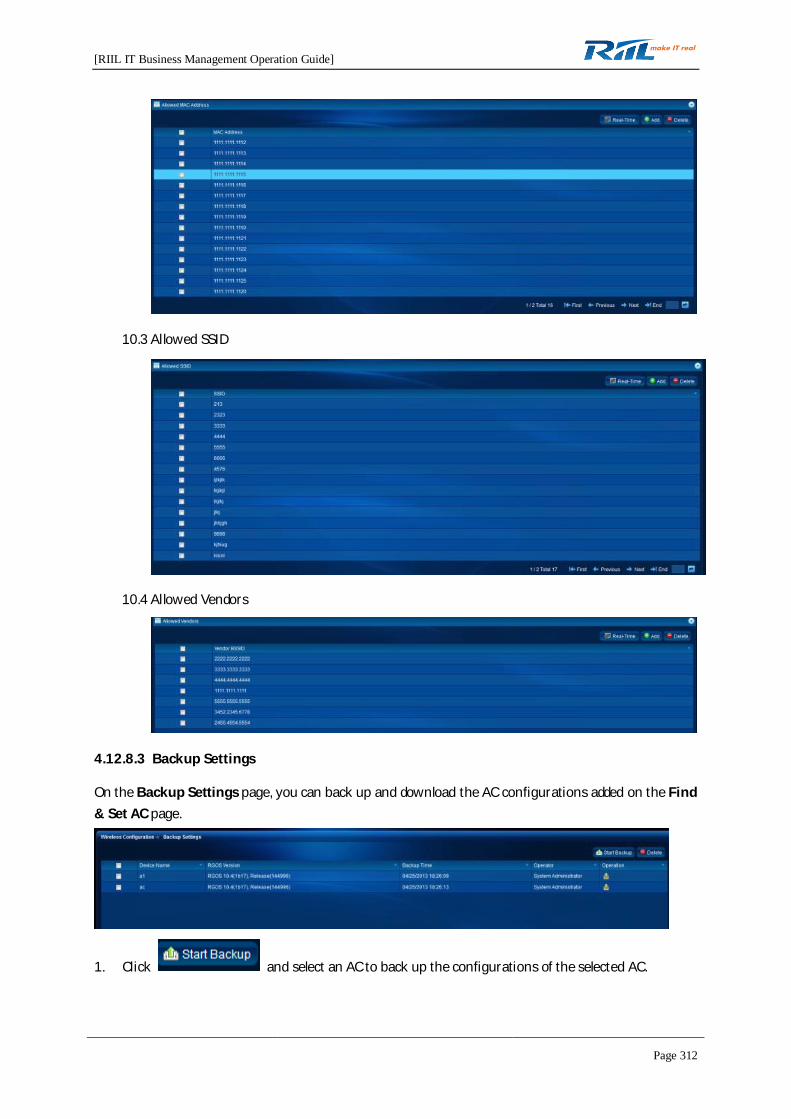
[RIIL IT Business Management Operation Guide]
Page 312
10.3 Allowed SSID
10.4 Allowed Vendors
4.12.8.3 Backup Settings
On the Backup Settings page, you can back up and download the AC configurations added on the Find& Set AC page.
1. Click and select an AC to back up the configurations of the selected AC.
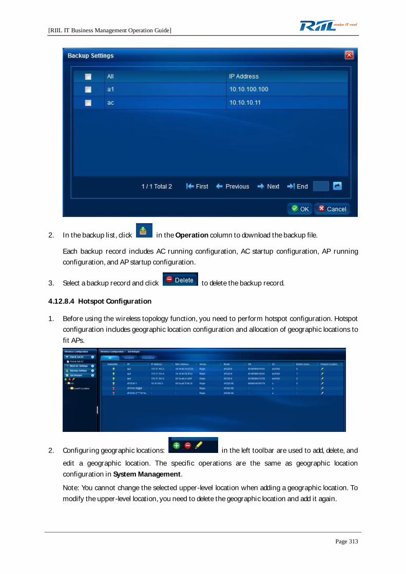
[RIIL IT Business Management Operation Guide]
Page 313
2. In the backup list, click in the Operation column to download the backup file.
Each backup record includes AC running configuration, AC startup configuration, AP runningconfiguration, and AP startup configuration.
3. Select a backup record and click to delete the backup record.
4.12.8.4 Hotspot Configuration
1. Before using the wireless topology function, you need to perform hotspot configuration. Hotspotconfiguration includes geographic location configuration and allocation of geographic locations tofit APs.
2. Configuring geographic locations: in the left toolbar are used to add, delete, and
edit a geographic location. The specific operations are the same as geographic locationconfiguration in System Management.
Note: You cannot change the selected upper-level location when adding a geographic location. Tomodify the upper-level location, you need to delete the geographic location and add it again.
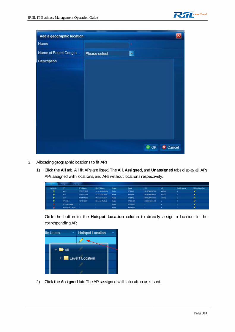
[RIIL IT Business Management Operation Guide]
Page 314
3. Allocating geographic locations to fit APs
1) Click the All tab. All fit APs are listed. The All, Assigned, and Unassigned tabs display all APs,APs assigned with locations, and APs without locations respectively.
Click the button in the Hotspot Location column to directly assign a location to thecorresponding AP.
2) Click the Assigned tab. The APs assigned with a location are listed.
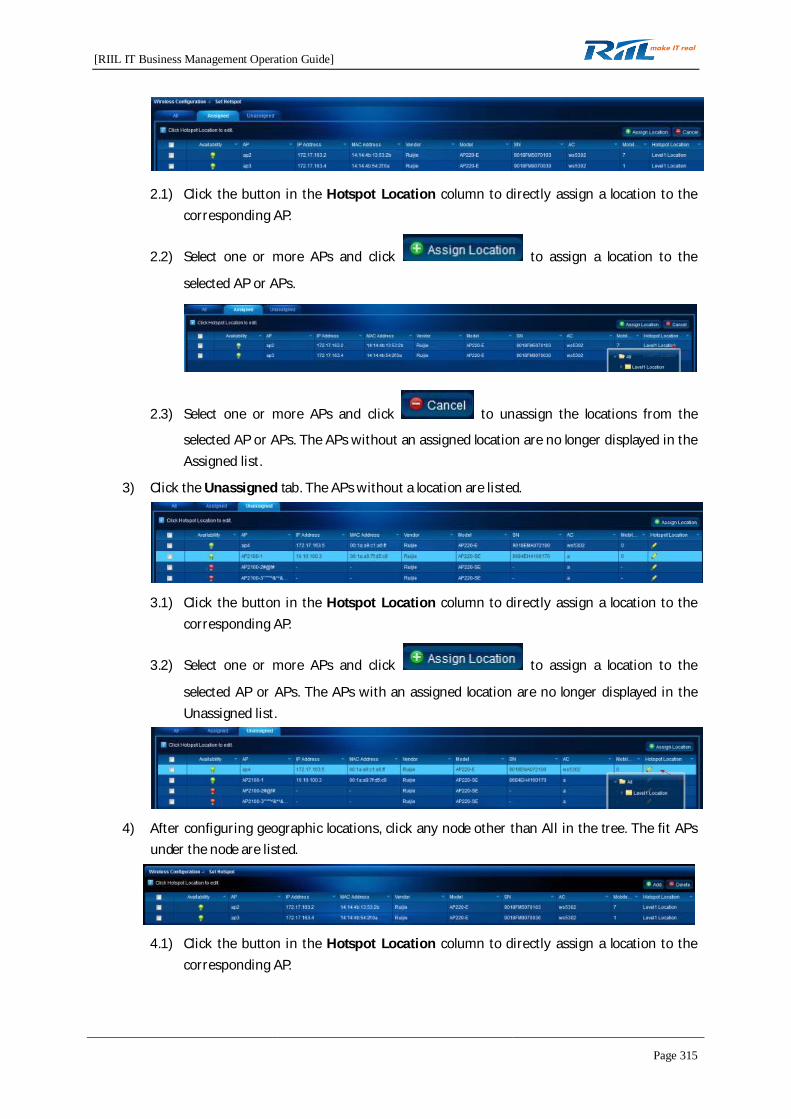
[RIIL IT Business Management Operation Guide]
Page 315
2.1) Click the button in the Hotspot Location column to directly assign a location to thecorresponding AP.
2.2) Select one or more APs and click to assign a location to the
selected AP or APs.
2.3) Select one or more APs and click to unassign the locations from the
selected AP or APs. The APs without an assigned location are no longer displayed in theAssigned list.
3) Click the Unassigned tab. The APs without a location are listed.
3.1) Click the button in the Hotspot Location column to directly assign a location to thecorresponding AP.
3.2) Select one or more APs and click to assign a location to the
selected AP or APs. The APs with an assigned location are no longer displayed in theUnassigned list.
4) After configuring geographic locations, click any node other than All in the tree. The fit APsunder the node are listed.
4.1) Click the button in the Hotspot Location column to directly assign a location to thecorresponding AP.
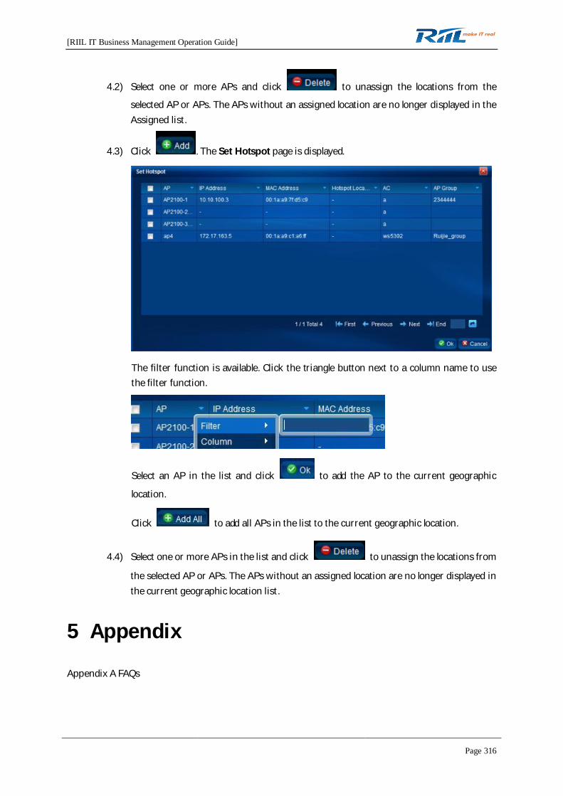
[RIIL IT Business Management Operation Guide]
Page 316
4.2) Select one or more APs and click to unassign the locations from the
selected AP or APs. The APs without an assigned location are no longer displayed in theAssigned list.
4.3) Click . The Set Hotspot page is displayed.
The filter function is available. Click the triangle button next to a column name to usethe filter function.
Select an AP in the list and click to add the AP to the current geographic
location.
Click to add all APs in the list to the current geographic location.
4.4) Select one or more APs in the list and click to unassign the locations from
the selected AP or APs. The APs without an assigned location are no longer displayed inthe current geographic location list.
5 Appendix
Appendix A FAQs