rigorous component-based system design using the bip … · tion, priority (bip) component...
TRANSCRIPT

© 2011 IEEE. Personal use of this material is permitted. However, permission to reprint/republish this material for advertising or promotional purposes or for creating
new collective works for resale or redistribution to servers or lists, or to reuse any copyrighted component of this work in other works must be obtained from the IEEE.
For more information, please see www.ieee.org/web/publications/rights/index.html.
www.computer.org/software
Rigorous Component-Based System Design Using the BIP Framework
Anandu Basu, Saddek Bensalem, Marius Bozga, Jacques Combaz,
Mohamad Jaber, Thanh-Hung Nguyen, and Joseph Sifakis
Vol. 28, No. 3
May/June 2011
This material is presented to ensure timely dissemination of scholarly and technical work. Copyright and all rights therein are retained by authors or by other copyright holders. All
persons copying this information are expected to adhere to the terms and constraints invoked by each author's copyright. In most cases, these works may not be reposted
without the explicit permission of the copyright holder.

074 0 -74 5 9 /11/ $ 2 6 . 0 0 © 2 011 I E E E MAY/JUNE 2011 | IEEE SOFTWARE 41
FOCUS: MULTIPARADIGM PROGRAMMING
FOCUS: MULTIPARADIGM PROGRAMMING
FOCUS: MULTIPARADIGM PROGRAMMING
FOCUSMULTIPARADIGM PROGRAMMING
FOCUS MULTIPARADIGM PROGRAMMING
SYSTEM DESIGN DIFFERS radically from pure software design in that it must account not only for functional requirements but also for extrafunc-tional requirements regarding the use of execution platform resources, such
as time, memory, and energy. Meet-ing extrafunctional requirements is essential in embedded system design and requires evaluation of how design choices affect overall system behavior. It also implies a deep understanding of
how the application software interacts with the underlying execution plat-form. Yet system designers currently lack rigorous techniques for deriving global models of a given system from models of its application software and execution platform.
We define a rigorous design flow as one that guarantees essential sys-tem properties. Most existing design flows that aspire to this goal privilege a unique programming model and asso-ciate it with a compilation chain that’s adapted for a given execution model. For example, synchronous system de-sign relies on synchronous program-ming models and usually targets hard-ware or sequential implementations on single processors.1 Alternatively, real-time programming, based on sched-uling theory for periodic tasks, tar-gets dedicated real-time multitasking platforms.2
At the Verimag Laboratory, we’ve been developing the behavior, interac-tion, priority (BIP) component frame-work to support a rigorous system de-sign flow. The BIP framework is
• model-based, describing all soft-ware and systems according to a single semantic model. This main-tains the flow’s overall coherency by guaranteeing that a description at step n+1 meets essential proper-ties of a description at step n.
• component-based, providing a family of operators for building composite components from sim-pler components. This overcomes the poor expressiveness of theoreti-cal frameworks based on a single operator, such as the product of au-tomata or a function call.
• tractable, guaranteeing correctness
Rigorous Component-Based System Design Using the BIP FrameworkAnanda Basu, Saddek Bensalem, Marius Bozga, Jacques Combaz, Mohamad Jaber, Thanh-Hung Nguyen, and Joseph Sifakis, Verimag Laboratory
// An autonomous robot case study illustrates the use
of the behavior, interaction, priority (BIP) component
framework as a unifying semantic model to ensure
correctness of essential system design properties. //
FOCUS: SOFTWARE COMPONENTS: BEYOND PROGRAMMING

42 IEEE SOFTWARE | WWW.COMPUTER.ORG/SOFTWARE
FOCUS: MULTIPARADIGM PROGRAMMING
FOCUS: MULTIPARADIGM PROGRAMMING
FOCUS: MULTIPARADIGM PROGRAMMING
FOCUSMULTIPARADIGM PROGRAMMING
FOCUS MULTIPARADIGM PROGRAMMING
FOCUS: SOFTWARE COMPONENTS: BEYOND PROGRAMMING
by construction and thereby avoid-ing monolithic a posteriori verifica-tion as much as possible.
BIP supports the construction of composite, hierarchically structured components from atomic components characterized by their behavior and interfaces. It lets developers compose components by layered application of interactions and priorities. This en-ables an expressiveness unmatched by any other existing formalism (see the related work sidebar).3 Architec-ture is a first-class concept in BIP, with well-defined semantics that system designers can analyze and transform.
In this article, we present the BIP component framework, highlight-ing its design flow and the main steps for deriving correct implementations from a given application’s software and a target platform. Case study re-sults from a BIP implementation of the Dala autonomous robot demonstrate its effectiveness.
The BIP Component FrameworkThe BIP framework uses connectors to specify possible interactions between components and priorities to select among possible interactions. Interac-tions express synchronization con-straints between the composed com-ponents’ activities, and priorities filter possible interactions to steer system evolution toward meeting performance requirements. The combination of in-teractions and priorities is the source of BIP’s expressive power. It defines a clean, abstract concept of architecture separate from behavior.
Atomic components are finite-state automata or Petri nets extended with data and ports. Ports are action names that can be associated with data and used for interactions with other compo-nents. States denote control locations where components wait for interac-tions. A transition is an execution step, labeled by a port, from one control lo-cation to another. Each transition has an associated guard and action—re-
spectively, a Boolean condition and a function defined on local data. In BIP, complex data and their transformations are written in C/C++.
A transition can be executed if its guard evaluates to true and some inter-action involving its port is enabled. The execution is an atomic sequence of two microsteps: first, execution of the in-teraction involving the port, which is a synchronization between several com-ponents with possible data exchange, followed by execution of the action as-sociated with the transition.
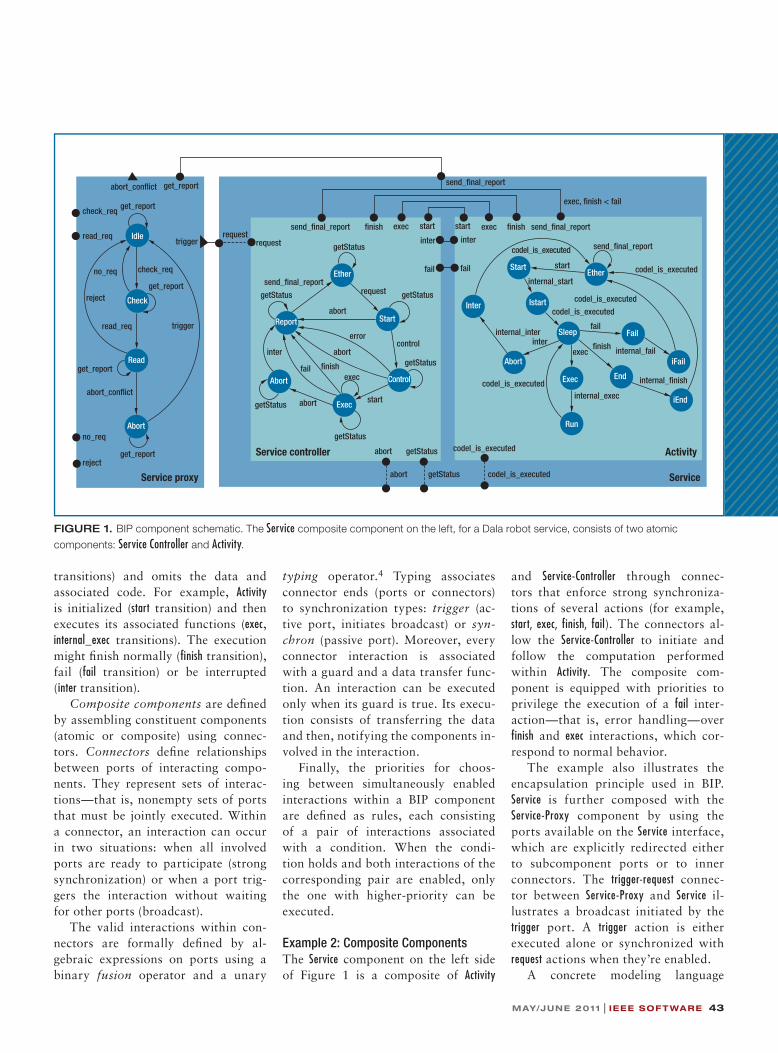
Example 1: Atomic ComponentsThe right side of Figure 1 shows two atomic components, Service-Controller and Activity, for the Dala robot controller. Activity wraps the long-time computa-tion of some specific application func-tion. Service-Controller provides execution control (triggering, canceling, error control, and so on) over the associ-ated Activity component. For simplici-ty’s sake, the figure presents only the skeleton control behavior (ports and
RELATED WORK IN COMPONENT FRAMEWORKSBIP differs significantly from existing component frameworks for software engineering. These often use multithreaded program-ming and point-to-point interaction mechanisms, such as function calls, for coordination between components. In contrast, BIP ex-ecutes atomic components concurrently and coordinates them in terms of high-level mechanisms such as protocols and scheduling policies.
Because BIP focuses on the organization of computation between components, it can be viewed as an architecture description language (ADL). Like other existing ADLs, such as Acme (www.cs.cmu.edu/~acme)1 and Darwin,2 BIP uses the connector concept to express coordination between components. Nonetheless, connectors in BIP are stateless. The architecture, consisting of connectors and priorities, is clearly distinguished from behavior.
Another significant difference from other frameworks is that BIP is intended for system modeling. It directly encompasses timing and resource management. Other system modeling formalisms either seek generality to the detriment of
rigorousness, such as (Systems Modeling Language (SySML)3 and (Architecture Analysis and Design Language (AADL; http://standards.sae.org/as5506a),4 or limit their scope to specific computation models, such as Ptolemy.5
References 1. D. Garlan, R. Monroe, and D. Wile, “Acme: An Architecture Description
Interchange Language, Proc. 1997 Conf. Centre for Advanced Studies on Collaborative Research (CASCON 97), IBM Press, 1997, pp. 169–183.
2. J. Magee and J. Kramer, “Dynamic Structure in Software Architectures,” Proc. 4th ACM SIGSOFT Symp. Foundations of Software Eng. (SIGSOFT 96), ACM Press, 1996, pp. 3–14.
3. OMG Systems Modeling Language SysML (OMG SysML), v. 1.2, Object Management Group, 2010; www.omg.org/spec/SysML/1.2.
4. P.H. Feiler, B. Lewis, and S. Vestal, “The SAE Architecture Analysis and Design Language (AADL): A Standard for Engineering Performance Critical Systems,” IEEE Conf. Computer Aided Control Systems Design (CACSD 06), IEEE Press, 2006, pp. 1206–1211.
5. J. Eker et al., “Taming Heterogeneity: The Ptolemy Approach,” Proc. IEEE, vol. 91, no. 1, 2003, pp. 127–144.
MAY/JUNE 2011 | IEEE SOFTWARE 43
transitions) and omits the data and associated code. For example, Activity is initialized (start transition) and then executes its associated functions (exec, internal_exec transitions). The execution might fi nish normally (fi nish transition), fail (fail transition) or be interrupted (inter transition).
Compositecomponents are defi ned by assembling constituent components (atomic or composite) using connec-tors. Connectors defi ne relationships between ports of interacting compo-nents. They represent sets of interac-tions—that is, nonempty sets of ports that must be jointly executed. Within a connector, an interaction can occur in two situations: when all involved ports are ready to participate (strong synchronization) or when a port trig-gers the interaction without waiting for other ports (broadcast).
The valid interactions within con-nectors are formally defi ned by al-gebraic expressions on ports using a binary fusion operator and a unary
typing operator.4 Typing associates connector ends (ports or connectors) to synchronization types: trigger (ac-tive port, initiates broadcast) or syn-chron (passive port). Moreover, every connector interaction is associated with a guard and a data transfer func-tion. An interaction can be executed only when its guard is true. Its execu-tion consists of transferring the data and then, notifying the components in-volved in the interaction.
Finally, the priorities for choos-ing between simultaneously enabled interactions within a BIP component are defi ned as rules, each consisting of a pair of interactions associated with a condition. When the condi-tion holds and both interactions of the corresponding pair are enabled, only the one with higher-priority can be executed.
Example 2: Composite ComponentsThe Service component on the left side of Figure 1 is a composite of Activity
and Service-Controller through connec-tors that enforce strong synchroniza-tions of several actions (for example, start, exec, finish, fail). The connectors al-low the Service-Controller to initiate and follow the computation performed within Activity. The composite com-ponent is equipped with priorities to privilege the execution of a fail inter-action—that is, error handling—over finish and exec interactions, which cor-respond to normal behavior.
The example also illustrates the encapsulation principle used in BIP. Service is further composed with the Service-Proxy component by using the ports available on the Service interface, which are explicitly redirected either to subcomponent ports or to inner connectors. The trigger-request connec-tor between Service-Proxy and Service il-lustrates a broadcast initiated by the trigger port. A trigger action is either executed alone or synchronized with request actions when they’re enabled.
A concrete modeling language
Ether
Start
Control
Exec
Abort
Report
getStatus
getStatus
getStatus
abort
error
fail �nish
inter
getStatus
send_�nal_report
getStatus
abortcontrol
startabort
internal_start
start
codel_is_executed
interinternal_inter
codel_is_executed
exec
internal_exec
�nish
fail
codel_is_executed
internal_�nish
internal_fail
send_�nal_reportcodel_is_executedinterinter
exec
getStatus
start startexec
failfail
Service
�nishsend_�nal_report
abort getStatusService controller codel_is_executed Activity
codel_is_executed
exec send_�nal_report�nish
exec, �nish < fail
codel_is_executedgetStatusabort
requestrequest
request
get_reportabort_con�ict
check_req
get_report
get_report
get_report
abort_con�ict
reject
read_req trigger
Service proxy
trigger
get_report
no_req
send_�nal_report
reject
check_req
no_req
read_req
EtherStart
Exec
Abort
Istart
Sleep
Run
Inter
End
iEnd
iFail
Fail
Read
Idle
Check
Abort
FIGURE 1. BIP component schematic. The Service composite component on the left, for a Dala robot service, consists of two atomic
components: Service Controller and Activity.

44 IEEE SOFTWARE | WWW.COMPUTER.ORG/SOFTWARE
FOCUS: MULTIPARADIGM PROGRAMMING
FOCUS: MULTIPARADIGM PROGRAMMING
FOCUS: MULTIPARADIGM PROGRAMMING
FOCUSMULTIPARADIGM PROGRAMMING
FOCUS MULTIPARADIGM PROGRAMMING
FOCUS: SOFTWARE COMPONENTS: BEYOND PROGRAMMING
supports the BIP framework. The BIP language leverages C++-style variables and data-type declarations, expres-sions, and statements. It also provides additional structural syntactic con-structs for defi ning component be-havior and describing connectors and priorities. Moreover, it provides con-structs for handling parametric and hi-erarchical descriptions and for express-ing timing constraints associated with behavior.
The BIP Design FlowFigure 2 illustrates a rigorous system design fl ow that uses BIP as a unifying semantic model to ensure consistency between the different design steps.
The design fl ow involves four dis-tinct steps that translate the applica-tion software into a BIP model and
progressively derive an implementa-tion by applying source-to-source transformations:
1. Translatingtheapplicationsoftwareinto a BIP model. The translation focuses on the defi nition of adequate interfaces. It encapsulates and reuses the application software’s data struc-tures and functions.
2. Integratingarchitectural constraintsin the application software model. The integration derives a system model in BIP from a model of the hardware target platform and a mapping.
3. Translating interactions and pri-oritiesof the system model in terms of protocols using send/receive primitives.
4. GeneratingdeployableCcodefrom
which an implementation can be obtained.
The transformations are “correct by construction” because the obtained BIP models are observationally equivalent to the original model. In particular, they preserve the application software’s safety properties. Furthermore, we de-veloped D-Finder, a verifi cation tool that checks essential safety properties of the application software.
Figure 3 shows an extensible toolset that supports the entire BIP design fl ow, including D-Finder.
Translating Application Software into BIPThe fi rst step in the design fl ow con-sists of generating a BIP model for the application software. We have devel-oped a general method for generating BIP models from languages with well-defi ned operational semantics. It in-volves the following steps for a given application software written in a lan-guage L:
1. TranslatingthesourcelanguageL’satomic components into BIP com-ponents. The translation focuses on the defi nition of adequate inter-faces. It encapsulates and reuses the application software’s data struc-tures and functions.
2. Translatingthecoordinationmecha-nisms betweenapplicationsoftwarecomponents into the target BIP model’s connectors and priorities.
3. Generating a BIP component thatmodels L’s operational seman-tics. This component plays the role of an engine coordinating the ex-ecution of the application software components.
We developed BIP model genera-tors for several programming models used by embedded system develop-ers (the source-to-source transformers in Figure 3). The generated models preserve the structure of the initial
Mapping
Deployable code
Translation
Performanceanalysis
D−Finder
Hardware execution platform
Integration ofarchitectural constraints
Application software
System model in BIP
Code generation
software model in BIPApplication
Integration ofcommunication protocols
Distributed system model in S/R−BIP
FIGURE 2. BIP design � ow. An implementation—that is, deployable code—is generated
from the application software, a model of the hardware platform, and a mapping.

MAY/JUNE 2011 | IEEE SOFTWARE 45
programs, their size is linear with re-spect to the initial program size, and they’re easy for the system developers to understand.
Using D-Finder for Compositional Verifi cationD-Finder bases its compositional ver-ifi cation method on computing in-variants.5 It computes increasingly stronger invariants for composite components as conjunctions of atomic components’ local invariants and in-teraction invariants that characterize the composition glue. Static analysis of atomic components generates the lo-cal component invariants. Interaction invariants are generated from abstrac-tions of the composite component to be verifi ed.
We recently improved this method to take advantage of the incremen-tal system design process, which pro-ceeds by adding new interactions to a component under construction. Each time a new interaction is added, it’s possible to verify whether the result-ing component violates a given prop-erty and so discover design errors as they appear. The incremental verifi -cation technique6 uses suffi cient con-ditions to ensure the preservation of invariants when new interactions are added during the component construc-tion process. If these conditions aren’t satisfi ed, D-Finder generates new in-variants by reusing invariants of the constituent components. Reusing in-variants considerably reduces the veri-fi cation effort.
The D-Finder tool implements the compositional verifi cation techniques for checking the deadlock-freedom of systems described in BIP.7 Experimen-tal results on classical benchmarks show that D-Finder can run exponen-tially faster than existing monolithic verifi cation tools, such as NuSMV.
Generating ImplementationsThe BIP toolset offers several compila-
tion chains, targeting different execu-tion platforms. To implement BIP on single-core platforms requires using engines—that is, dedicated middle-ware for execution of the C++ code au-togenerated from BIP descriptions. BIP currently provides two engines: one for real-time single-thread and one for multithread execution. For multi-thread execution, each atomic compo-nent is assigned to a thread, with the engine itself being a thread. Commu-nication occurs only between atomic components and the engine—never directly between different atomic components.
To generate distributed implemen-tations from BIP models, we trans-form them into send/receive (S/R)-BIP models,8 a subclass of models in which protocols using S/R primitives replace multiparty interactions. From S/R-BIP models and a mapping of atomic com-ponents into a platform’s processing
elements, we generate effi cient C/C++ or message passing interface (MPI) code.
We use the following sequence of correct-by-construction transforma-tions, which preserve observational equivalence.8 First, given a user-defi ned partition of a BIP system mod-el’s interactions, we break the atomi-city of its transitions by separating the interaction from the computation. We then replace multiparty interactions with protocols that use S/R primitives. Moreover, we structure the target S/R-BIP model in three layers:
• The component layer consists of the original model’s atomic compo-nents in which each port involved in strong interactions is replaced by a pair of corresponding S/R ports.
• The interactionprotocollayer con-sists of a set of components, each of which manages a class of the par-
C++ generator(engine-based)
BIP executable
BIP engine runtime
Platform
D-Finder
Validation
nesC DOL Simulink
Source-to-source transformers
C Lustre
Distributed platform
Transformers
BIP executable BIP executable BIP executable
Communications primitives (Send/Receive)
BIP
BIP language
Languagefactory
Code generation and runtimes
Parser
Distributed BIPgenerator
C/C++C/C++C/C++
C/C++
S/R BIP model
BIP modelBIP metamodel
BIP compiler
FIGURE 3. BIP toolset. The tools include translators from various programming models,
veri� cation tools, source-to-source transformers, and C/C++ code generators for BIP models.

46 IEEE SOFTWARE | WWW.COMPUTER.ORG/SOFTWARE
FOCUS: MULTIPARADIGM PROGRAMMING
FOCUS: MULTIPARADIGM PROGRAMMING
FOCUS: MULTIPARADIGM PROGRAMMING
FOCUSMULTIPARADIGM PROGRAMMING
FOCUS MULTIPARADIGM PROGRAMMING
FOCUS: SOFTWARE COMPONENTS: BEYOND PROGRAMMING
tition’s interactions. The protocol detects whether interactions are enabled and executes them after resolving confl icts either locally or with assistance from the third layer.
• The conflict resolution protocollayer consists of distributed algo-rithms for resolving confl icts as requested by the interaction pro-tocol layer. The confl ict resolution protocol, which basically solves a committee coordination problem, uses either a fully centralized, to-ken-ring, or dining philosophers algorithm.9,10
In the second step, we use the three-layer S/R-BIP model and a mapping of its atomic components on processors to generate either an MPI program or a set of plain C/C++ programs that use TCP/IP communication. This process statically composes atomic components running on the same processor to ob-tain a single observationally equivalent component, and reduce coordination overhead at runtime.
Case Study: Dala Robot ControllerWe used BIP to develop a new version of the functional layer of the Dala ro-bot controller from an existing version developed using the GeNoM frame-work.11 We presented preliminary results of this work elsewhere,12 in-cluding the complete modeling of the functional layer, its functional verifi -cation, and the synthesis of a correct-by-construction software controller. Here, we briefl y introduce the model and summarize our latest results on the verifi cation of deadlock-freedom.
Functional layer design in BIP in-
volves three steps:
1. Hierarchical decomposition intocomponents. A tree structure rep-resents the overall architecture with its root corresponding to the func-tional layer and its leaves to atomic components. The grammar in Fig-ure 4 shows how to obtain the de-signed system as the incremental composition of components.
2. Description of each atomic com-ponent’s behavior. In addition to component abstractions, such as those we described for the Service-Controller and Activity compo-nents (see Figure 1), the functional layer includes Poster components to store and communicate data as-sociated with different modules; Timer components that trigger peri-odic, time-dependent computations; Scheduler-Activity and Execution-Controller components to control execution control at the module level.
3. Description of composite compo-nents. Atomic components are com-posed using only interactions and priorities because BIP is expressive enough to describe any kind of co-ordination solely through architec-tural constraints.
The entire functional layer contains eight distinct modules. Their functionalities are
• collecting data from the laser sen-sors (LaserRF),
• generating an obstacle map (Aspect),• navigating using the near diagram
approach (NDD),• managing the low-level robot wheel
controller (Rfl ex),
• emulating the communication with an orbiter (Antenna),
• providing power and energy for the robot (Battery),
• heating the robot in a low-tempera-ture environment (Heating), and
• controlling the movement of two cameras (Platine).
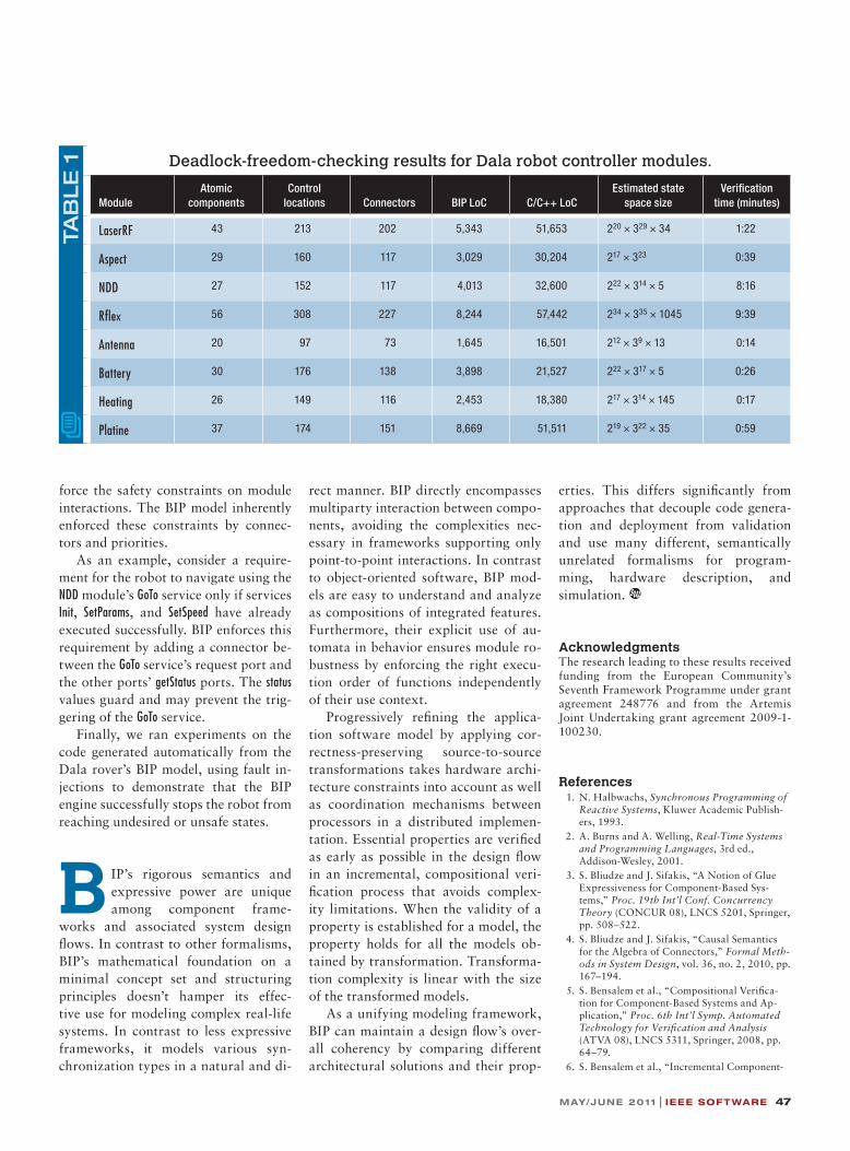
Table 1 presents characteristics of the software componentized in BIP. For example, the NDD module uses 117 connectors to interconnect 27 atomic components comprising 152 control lo-cations. This module consists of 5,343 lines of BIP code and calls external functions totalizing 51,653 lines of C/C++ code. In total, the functional layer modules use 268 atomic compo-nents and 1,141 connectors. The whole model has 37,294 lines of BIP code and calls more than 279,818 lines of exter-nal C/C++ code.
We used D-Finder to formally ver-ify the functional layer’s BIP model for deadlock-freedom and other safety properties, such as data freshness. We have the capability to check safety and deadlock freedom properties for all the modules. We successively detected (and corrected) two deadlocks, one in Antenna and the other in NDD. We also successfully verifi ed deadlock free-dom for composition of three modules (LaserRF, Aspect, and NDD), and data fresh-ness between two modules (Aspect and NDD). Table 1 includes verifi cation times for checking deadlock freedom of indi-vidual modules as well as other charac-teristics such as the number of atomic components, control locations, lines of BIP code, and lines of C/C++ code.
We also used the BIP model to syn-thesize the execution controller that en-codes and enforces safety properties, thereby facilitating the development of safe, dependable robotic architectures. The initial version of this software used a centralized, hand-written, request-and-report checker (R2C) to ensure the proper execution of services and to en-
FunctionalLayer ::= (Module)+Module ::= (Service)+ . (Execution-Task) . (Poster)+Service ::= (Service-Controller) . (Activity)Execution-Task ::= (Timer) . (Scheduler-Activity) . (Execution-Controller)
FIGURE 4. Hierarchical decomposition of Functional Layer into components.
MAY/JUNE 2011 | IEEE SOFTWARE 47
force the safety constraints on module interactions. The BIP model inherently enforced these constraints by connec-tors and priorities.
As an example, consider a require-ment for the robot to navigate using the NDD module’s GoTo service only if services Init, SetParams, and SetSpeed have already executed successfully. BIP enforces this requirement by adding a connector be-tween the GoTo service’s request port and the other ports’ getStatus ports. The status values guard and may prevent the trig-gering of the GoTo service.
Finally, we ran experiments on the code generated automatically from the Dala rover’s BIP model, using fault in-jections to demonstrate that the BIP engine successfully stops the robot from reaching undesired or unsafe states.
B IP’s rigorous semantics and expressive power are unique among component frame-
works and associated system design flows. In contrast to other formalisms, BIP’s mathematical foundation on a minimal concept set and structuring principles doesn’t hamper its effec-tive use for modeling complex real-life systems. In contrast to less expressive frameworks, it models various syn-chronization types in a natural and di-
rect manner. BIP directly encompasses multiparty interaction between compo-nents, avoiding the complexities nec-essary in frameworks supporting only point-to-point interactions. In contrast to object-oriented software, BIP mod-els are easy to understand and analyze as compositions of integrated features. Furthermore, their explicit use of au-tomata in behavior ensures module ro-bustness by enforcing the right execu-tion order of functions independently of their use context.
Progressively refining the applica-tion software model by applying cor-rectness-preserving source-to-source transformations takes hardware archi-tecture constraints into account as well as coordination mechanisms between processors in a distributed implemen-tation. Essential properties are verified as early as possible in the design flow in an incremental, compositional veri-fication process that avoids complex-ity limitations. When the validity of a property is established for a model, the property holds for all the models ob-tained by transformation. Transforma-tion complexity is linear with the size of the transformed models.
As a unifying modeling framework, BIP can maintain a design flow’s over-all coherency by comparing different architectural solutions and their prop-
erties. This differs significantly from approaches that decouple code genera-tion and deployment from validation and use many different, semantically unrelated formalisms for program-ming, hardware description, and simulation.
AcknowledgmentsThe research leading to these results received funding from the European Community’s Seventh Framework Programme under grant agreement 248776 and from the Artemis Joint Undertaking grant agreement 2009-1-100230.
References 1. N. Halbwachs, SynchronousProgrammingof
ReactiveSystems, Kluwer Academic Publish-ers, 1993.
2. A. Burns and A. Welling, Real-TimeSystemsandProgrammingLanguages, 3rd ed., Addison-Wesley, 2001.
3. S. Bliudze and J. Sifakis, “A Notion of Glue Expressiveness for Component-Based Sys-tems,” Proc.19thInt’lConf.ConcurrencyTheory (CONCUR 08), LNCS 5201, Springer, pp. 508–522.
4. S. Bliudze and J. Sifakis, “Causal Semantics for the Algebra of Connectors,” FormalMeth-odsinSystemDesign, vol. 36, no. 2, 2010, pp. 167–194.
5. S. Bensalem et al., “Compositional Verifica-tion for Component-Based Systems and Ap-plication,” Proc.6thInt’lSymp.AutomatedTechnologyforVerificationandAnalysis (ATVA 08), LNCS 5311, Springer, 2008, pp. 64–79.
6. S. Bensalem et al., “Incremental Component-
TAB
LE
1 Deadlock-freedom-checking results for Dala robot controller modules.
ModuleAtomic
componentsControl
locations Connectors BIP LoC C/C++ LoCEstimated state
space sizeVerification
time (minutes)
LaserRF 43 213 202 5,343 51,653 220 × 329 × 34 1:22
Aspect 29 160 117 3,029 30,204 217 × 323 0:39
NDD 27 152 117 4,013 32,600 222 × 314 × 5 8:16
Rflex 56 308 227 8,244 57,442 234 × 335 × 1045 9:39
Antenna 20 97 73 1,645 16,501 212 × 39 × 13 0:14
Battery 30 176 138 3,898 21,527 222 × 317 × 5 0:26
Heating 26 149 116 2,453 18,380 217 × 314 × 145 0:17
Platine 37 174 151 8,669 51,511 219 × 322 × 35 0:59

48 IEEE SOFTWARE | WWW.COMPUTER.ORG/SOFTWARE
FOCUS: MULTIPARADIGM PROGRAMMING
FOCUS: MULTIPARADIGM PROGRAMMING
FOCUS: MULTIPARADIGM PROGRAMMING
FOCUSMULTIPARADIGM PROGRAMMING
FOCUS MULTIPARADIGM PROGRAMMING
FOCUS: SOFTWARE COMPONENTS: BEYOND PROGRAMMING
Based Construction and Verifi cation Using Invariants,” Proc.FormalMethodsonCom-puter-AidedDesign (FMCAD 10), Formal Methods in Computer-Aided Design, 2010, pp. 257–266; http://fmcad10.iaik.tugraz.at/Papers/FMCAD10.pdf.
7. S. Bensalem et al., “D-Finder: A Tool for Compositional Deadlock Detection and Verifi cation,” Proc.21stInt’lConf.ComputerAidedVerification (CAV 09), LNCS 5643, Springer, 2009, pp. 614–619.
8. B. Bonakdarpour et al., “From High-Level Component-Based Models to Distributed Implementations,” Proc.10thInt’lConf.EmbeddedSoftware (EmSoft 10), ACM Press, 2010, pp. 209–281.
9. K.M. Chandy and J. Misra, ParallelProgramDesign:AFoundation, Addison-Wesley Long-man, 1988.
10. R. Bagrodia, “Process Synchronization: Design and Performance Evaluation of Distrib-uted Algorithms,” IEEETrans.SoftwareEng., vol. 15, no. 9, 1989, pp. 1053–1065.
11. S. Fleury, M. Herrb, and R. Chatila, “GenoM: A Tool for the Specifi cation and the Implemen-tation of Operating Modules in a Distributed Robot Architecture,” Proc.1997IEEE/RSJInt’lConf.IntelligentRobotsandSystems (IROS 97), IEEE Press, 1997, pp. 842–848.
12. A. Basu et al., “Incremental Component-Based Construction and Verifi cation of a Robotic System,” Proc.18thEuropeanConf.ArtificialIntelligence (ECAI 08), IOS Press, 2008, pp. 631–635.
ANANDA BASU is a postdoctoral researcher at the Verimag Labora-tory. His research focuses on system-level modeling and performance analysis of mixed software-hardware systems and deriving their implementations on target hardware platforms. His interests include component-based modeling of embedded systems, in particular model-ing and simulation frameworks for complex and heterogeneous sys-tems. Basu has a PhD in computer science from the University Joseph Fourier, Grenoble. Contact him at [email protected].
SADDEK BENSALEM is a professor at the University of Joseph Fou-rier. His research focus is modeling and validation of real-time systems, including component-based modeling, verifi cation, and synthesis of distributed systems. Bensalem has a PhD in computer science from INP Grenoble (Institut National Polytechnique de Grenoble). Contact him at [email protected].
MARIUS BOZGA is a research engineer at CNRS (Centre National de la Recherche Scientifi que) and a member of the Verimag Laboratory. His research interests focus on component-based design for distributed real-time systems and include formal models for components, model-based design and implementation, and automatic validation methods and tools. Bozga has a PhD in computer science from the University of Grenoble. Contact him at [email protected].
JACQUES COMBAZ is a research engineer at CNRS (Centre National de la Recherche Scientifi que) and a member of the Verimag Laboratory. His research interests include the design of adaptive applications and real-time systems. He developed the real-time engine for BIP programs. Combaz has a PhD in mathematics and computer science from the University of Grenoble. Contact him at [email protected].
MOHAMAD JABER is a postdoctoral researcher at the Verimag Labo-ratory. His research focuses on component-based design and imple-mentation. Jaber has a PhD in computer science from the University of Grenoble. Contact him at [email protected].
THANH HUNG NGUYEN is a postdoctoral researcher at the Verimag Laboratory. His research interests are in the modeling and verifi cation of component-based systems. Nguyen has a PhD in computer science from the University of Grenoble. Contact him at [email protected].
JOSEPH SIFAKIS is a CNRS researcher and founder of the Verimag Laboratory. His research includes pioneering work on theoretical and practical aspects of concurrent systems specifi cation and verifi cation. His current interests include component-based design, modeling, and analysis of real-time systems with a focus on correct-by-construction techniques. Sifakis has a PhD in computer science from the University of Grenoble. In 2007, he shared the Turing Award with Ed Clarke and Allen Emerson for their contribution to model checking. Contact him at [email protected].
AB
OU
T T
HE
AU
TH
OR
S
Selected CS articles and columns are also available for free at http://ComputingNow.computer.org.
The magazine of computational tools and methods.
MEMBERS $49STUDENTS $25
www.computer.org/cise http://cise.aip.org
CiSE addresses large computational problems by sharing
›› effi cient algorithms
›› system software
›› computer architecture