rights / license: research collection in copyright - non …49796/...diss. eth no. 23592...
TRANSCRIPT

Research Collection
Doctoral Thesis
Inhomogeneous Deformations of Thermoplastics for PhysicallyAdaptive Soft Matter Robots
Author(s): Culha, Utku
Publication Date: 2016
Permanent Link: https://doi.org/10.3929/ethz-a-010735372
Rights / License: In Copyright - Non-Commercial Use Permitted
This page was generated automatically upon download from the ETH Zurich Research Collection. For moreinformation please consult the Terms of use.
ETH Library

DISS. ETH NO. 23592
Inhomogeneous Deformations ofThermoplastics for Physically Adaptive
Soft Matter Robots
A thesis submitted to attain the degree of
DOCTOR OF SCIENCES of ETH ZURICH(Dr. sc. ETH Zurich)
presented by
UTKU CULHAM.Sc., Bilkent University
born on 1 January 1988
citizen of Republic of Turkey
accepted on the recommendation of
Prof. Dr. Fumiya Iida, examinerProf. Dr. Dario Floreano, co-examinerProf. Dr. Roger Gassert, co-examiner
2016

Inhomogeneous Deformations ofThermoplastics for Physically Adaptive Soft
Matter Robots
Utku Culha
2016

Bio-Inspired Robotics LabInstitute of Robotics and Intelligent SystemsETH ZurichSwitzerland
© 2016 Utku Culha. All rights reserved.

Abstract
In recent years robotics researchers have started using soft materials to build robots inspired fromsimple organisms, plants and animals which demonstrate impressive physical and behaviouraladaptations originating from their soft and deformable body structures. Unlike rigid materi-als used in conventional robots, soft materials such as polymers and gels are continuum andvisco-elastic mediums which can exhibit large deformations in many directions. Usage of thesematerials enables robotic systems to perform adaptive interactions with uncertain and unstruc-tured environments during various tasks such as locomotion, manipulation and inspection.
In biology, many important functions emerge from the formation of well-defined structuresas a result of symmetry breaking in the cellular scale. In symmetry breaking, the non-uniformdistribution of initiating stimuli around the soft and deformable cells contributes to the gen-eration of asymmetric body forms. These asymmetric formations play important roles in thedevelopment of physical adaptations which are essential for survival. The contracting motionof muscle fibres (cell motility), growth and morphogenesis (cell division), healing (cell fusion)and specialisation of neuron axons (cell polarity) are several examples to the adaptive functionsbased on symmetry breaking. The mechanisms, conditions and physics of the formation asym-metric forms which lead to adaptive functions are well established and investigated in biology.However, there has been no clear theory and systematic investigation so far to discuss how defor-mation of soft continuum structures can be used for the emergence of physical and behaviouraladaptations in autonomous robotic systems.
This dissertation proposes a systematic investigation on the utilisation of inhomogeneousdeformations of soft materials for the generation of physical and behavioural adaptations onrobotic platforms. Inhomogeneous deformations take place in a non-uniform manner through-out a continuum body which can result in generating asymmetric forms similar to examplesin biology. Soft materials present similarities to the collective behaviours of highly distributedneighbouring cells due to their molecular structure and physical properties under the influence ofvarious stimuli. Especially thermoplastics provide suitable conditions to exhibit inhomogeneousdeformations through the application of thermal and mechanical stimuli combinations. There-fore, this dissertation proposes different mechanisms to generate asymmetric forms by inducinginhomogeneous deformations on thermoplastic materials. These asymmetric forms can be usedfor the generation of sensing and motion functions which are crucial in an autonomous systemto exhibit physical and behavioural adaptations.
The conceptual discussion on physical adaptation is realised with four case studies whichdemonstrate the three contributions of this dissertation: regulation of plasticity for structuraladaptation, differential stiffness for the emergence of motions, and sensing of soft deformationsusing adjustable morphology. The case studies present robotic platforms which demonstratesensing of deformations on robot’s own body, sensing of softness and temperature of unknownobjects in the environment, locomotion in free space by fabricating draglines, and adaptivemanipulation with anthropomorphic and compliant joint designs. Regulation of plasticity forstructural adaptation is used commonly in all of the case studies where thermoplastic materialsare moulded into asymmetric forms with mechanisms that firstly regulate their plasticity viaheat induction and secondly deform those using mechanical stimuli. The emergence of motionfrom the differential stiffness is observed in the dragline forming mobile robot and the robotic
i

Abstract
hand with compliant joints, which exploit inhomogeneous deformations caused by the non-uniform stiffness distribution in the soft material compositions. And sensing of soft deformationswith adjustable morphology is utilised in the first two robotic platforms which can distinguishdifferent stimuli, and adjust their sensitivity by only changing the morphology of the sensorsthey are fabricating. The case studies in this dissertation demonstrate working examples ofphysical and behavioural adaptation on robotic platforms by using inhomogeneous deformationof soft materials. The suggested systematic investigation and the findings in the dissertationcontribute to the development of robotic platforms which can autonomously adapt to theirenvironments by changing their body structures. These autonomous and physically adaptivesoft robots can be useful in areas such as search and rescue, invasive surgery, rehabilitation andprosthetics, inspection and exploration, and human machine interaction. Further, suggestedinvestigation can allow the realisation of concepts such as morphogenesis, healing or growth,which are unachievable with conventional methods or materials, and provide experimental aidto a better understanding of neuroscience, evolution and emergent behaviours.
ii

Kurzfassung
In den letzten Jahren haben Forscher in der Robotik angefangen weiche Materialien zum Bauvon Robotern einzusetzen, welche von einfachen Organismen, Pflanzen und Tieren inspiriert sindund eindrucksvolle Anpassungen ihrer Form und ihres Verhaltens zeigen, deren Ursprung in wei-chen und verformbaren Korperstrukturen liegt. Im Gegensatz zu steifen Materialien, welche inkonventionellen Robotern eingesetzt werden, sind weiche Materialien wie Polymere und GelsKontinua und visko-elastische Medien, die grosse Verformungen in alle Richtungen aufweisenkonnen. Die Benutzung dieser Materialien ermoglicht es Robotersystemen in unbekannten undunstrukturierten Umgebungen adaptive Interaktionen auszufuhren um unterschiedlicher Aufga-ben wie Fortbewegung, Manipulation oder Inspektion durchzufuhren.
In der Biologie ergeben sich viele wichtige Funktionen durch die Bildung von wohldefiniertenStrukturen aufgrund von Symmetriebrechung auf Zellebene. Bei der Symmetriebrechung tragtdie nicht-uniforme Verteilung initiierender Stimuli auf weiche und verformbare Zellen zur Bil-dung asymmetrischer Korperformen bei. Diese asymmetrischen Formen spielen wichtige Rollenbei der Entwicklung physischer Anpassungen welche essentiell furs Uberleben sind. Das Zusam-menziehen von Muskelfasern (Zellmotilitat), Wachstum und Morphogenese (Zellteilung), Heilung(Zellfusionierung) und die Spezialisierung von neuronalen Axonen (Zellpolaritat) sind mehrereBeispiele fur die adaptiven Funktionen welche auf Symmetriebrechung basieren. Die Mechanis-men, Bedingungen und die Physik der Bildung asymmetrischer Formen welche zu adaptivenFunktionen fuhren sind etabliert und werden in der Biologie untersucht. Bislang fehlen jedocheine klare Theorie und systematische Untersuchungen wie die Verformung von weichen Konti-nua genutzt werden kann fur die Emergenz physischer und Verhaltensanpassungen in autonomenRobotersystemen.
In dieser Dissertation wird eine systematische Untersuchung der Anwendung von inhomoge-nen Deformationen von weichen Materialien zur Schaffung physischer und Verhaltensanpassun-gen von Roboterplattformen vorgenommen. Inhomogene Verformungen finden in nicht-uniformerArt in Kontinuumskorpern statt, welche in der Schaffung asymmetrischer Formen ahnlich zu bio-logischen Beispielen resultieren konnen. Weiche Materialen weisen, aufgrund ihrer molekulareStruktur und physischen Eigenschaften unter verschiedenen Einflussen, Ahnlichkeiten zum kol-lektiven Verhalten von verteilten Nachbarzellen auf. Insbesondere Thermoplaste verfugen ubergeeignete Eigenschaften um inhomogene Verformungen unter kombinierten thermischen undmechanischen Einflussen aufzuzeigen. Deshalb werden in dieser Dissertation unterschiedlicheMechanismen aufgezeigt, um asymmetrische Formen durch das Einbringen inhomogener Defor-mationen in thermoplastischen Materialien zu generieren. Diese asymmetrischen Formen konnenfur die Bildung von Sensor- und Aktorfunktionen genutzt werden, welche fur autonome Systemeelementar sind um physische und Verhaltensanpassungen auszufuhren.
Die konzeptionelle Diskussion physischer Anpassung ist in vier Fallstudien umgesetzt, wel-che die drei Beitrage dieser Dissertation aufzeigen: Die Regulation von Plastizitat fur struktu-relle Anpassungen, differentielle Steifigkeit fur das Aufkommen von Bewegungen und das Er-kennen weicher Deformationen mittels einer anpassungsfahiger Morphologie. Diese Fallstudienprasentieren Roboterplattformen welche die Erkennung von Deformationen des eigenen Robo-terkorpers, die Messung von Weichheit und Temperatur unbekannter Objekte in der Umgebung,die Fortbewegung im freien Raum durch die Herstellung von Halteseilen sowie anpassungsfahige
iii

Kurzfassung
Manipulation mit anthropomorphen und nachgiebigen Gelenkdesigns aufzeigen. Die Regulationder Plastizitat fur strukturelle Anpassungen wird in allen Fallstudien genutzt wobei thermoplas-tische Materialien asymmetrisch geformt werden mit Mechanismen die erstens deren Plastizitatuber die Einbringung von Hitze regeln und zweitens die Strukturen uber mechanische Einflusseverformen. Die Entstehung von Bewegung aus differentieller Steifigkeit wird an einem Halteseil-bildenden mobilen Roboter und einer Roboterhand mit nachgiebigen Gelenken untersucht, wel-che inhomogene Deformationen ausnutzen die durch die nichthomogene Steifigkeitsverteilung inweichen Materialkombinationen entstehen. Die Erkennung weicher Deformationen mit anpassba-rer Morphologie wird in den ersten beiden Roboterplattformen genutzt, welche unterschiedlicheReize unterscheiden konnen und die die Sensitivitat einstellen indem die Morphologie der Sen-soren die die Roboter herstellen geandert wird. Die Fallstudien in dieser Dissertation demons-trieren funktionierende Beispiele physischer und Verhaltensanpassung auf Roboterplattformendurch die Nutzung inhomogener Deformation weicher Materialien. Die vorgeschlagene systema-tische Untersuchung und die Erkenntnisse aus dieser Dissertation tragen zur Entwicklung vonRoboterplattformen bei, welche sich autonom an die Umgebungen anpassen konnen indem sieihre Korperstruktur verandern. Diese autonomen und physisch anpassbaren weichen Roboterkonnen nutzlich sein in Gebieten wie bei Such- und Rettungseinsatzen, invasiven Operationen,Rehabilitation und Prothetik, Inspektion und Erkundung sowie der Mensch-Maschine Interak-tion. Ausserdem kann die vorgeschlagene Untersuchung die Realisierung von Konzepten wieMorphogenese, Heilung oder Wachstum ermoglichen, welche mit konventionellen Materialienund Methoden nicht erreicht werden konnen. Die Untersuchung bietet experimentelle Hilfe furein besseres Verstandnis von Neurowissenschaft, Evolution und emergentem Verhalten.
iv

Acknowledgments
Since the beginning of my doctoral research in 2012, I have had the chance to meet and work withgreat people whose presence and collaboration have influenced and boosted my personal andprofessional life. I would like to take this opportunity to thank these people for their personal,philosophical and scientific support in completing this dissertation.
First, I would like to thank Prof. Dr. Fumiya Iida for granting me the opportunity to workwith him for my doctoral research in bio-inspired robotics field. He has been my supervisor andmentor on different philosophical and scientific discussions so far. His enthusiasm in lookingfor new and crazy solutions to big problems during hours long discussions have been the mainmotivation for my time in his lab and surely will be a driving force for the academic life I amplanning to pursue in the following years.
Also, I would like to thank my co-examiners Prof. Dr. Dario Floreano and Prof. Dr. RogerGassert for their contribution to my dissertation for their invaluable feedback. I would like tothank Prof. Dr. Roland Siegwart for his support during the last year of my research which madethe completion of my dissertation possible.
My parents and my family have been the greatest source of support and inspiration to allmy life achievements, and this dissertation is just another one of them. I owe what I have nowto their endless support; therefore these lines will not be sufficient enough to thank them. Iwould also like to thank Roisin Braddell for whom she has been in my life.
Throughout my studies I have had the privilege to work with the best of colleagues someonecan have. I was lucky to work with a large group of people due to my times in ETH Zurich andUniversity of Cambridge. To begin with the ETH Zurich members, I am thankful to Dr. SuryaG. Nurzaman, Dr. Hugo G. Marques and Dr. Kohei Nakajima for their prior influence anddirections on my research and Dr. Hung Vu Quy, Dr. Amir Jafari and Dr. Murat Reis for theircollaboration during my studies. I would like to thank my fellow cohorts who have been in thesame doctoral process; Dr. Liyu Wang and Dr. Luzius Brodbeck (especially for his help on theGerman translation) who have successfully completed their degrees, and Fabian Gunther whohas been going through the same process as I am, and former members Derek Leach, XiaoxiangYu and Nandan Maheshwari. I should also thank Keith Gunura, Bryan Anestesiades and SimonHauser as inseparable members of our research group. These people have been there for all theideas, success, stress and joy we have shared throughout the study years. I also would like tothank Ji Hyun Lee and Rahel Haller for being the best in their administrative support.
In addition to the ETH members, my colleagues during the last year of my study in theUniversity of Cambridge, Dr. Andre Rosendo, Dr. Ali Ozgur Yontem, Fabio Giardina and JosieHughes have been both personally and intellectually supportive to me, which I am thankful for.
My research presented in this dissertation has also been shaped by the contribution of theBachelor and Master’s students whom I had the chance to supervise. I want to thank UmarWani, Milan Jovic, Cinzia Peruzzi and Vuk Vujovic from ETH Zurich and Edward Bentley, JoeWatson and Sarah Wong from University of Cambridge.
Lastly, I would like to thank all my friends, especially to my Turkish friends in Zurich, fortheir personal and intellectual support which made the life during a stressful doctoral processfun and easy. I have been very lucky to meet every single one of them.
v

Acknowledgments
Financial SupportThis work was supported by the Swiss National Science Foundation Professorship Grant No.PP00P2123387/1, and the ETH Zurich Research Grant ETH-23-10-3.
vi

Contents
Abstract i
Kurzfassung iii
Acknowledgments v
Preface xi
1 Introduction 11.1 Physical Adaptation in Biology . . . . . . . . . . . . . . . . . . . . . . . . . . . . 1
1.1.1 Symmetry Breaking . . . . . . . . . . . . . . . . . . . . . . . . . . . . . . 21.1.2 Role of Deformation in Functionality . . . . . . . . . . . . . . . . . . . . . 3
1.2 Physical Adaptation in Robots . . . . . . . . . . . . . . . . . . . . . . . . . . . . 31.2.1 Modular Self-Reconfigurable and Swarm Robots . . . . . . . . . . . . . . 41.2.2 Soft Matter Robots . . . . . . . . . . . . . . . . . . . . . . . . . . . . . . . 51.2.3 Challenges for Achieving Physical Adaptation in Robots . . . . . . . . . . 7
1.3 Inhomogeneous Deformations for Physical Adaptations . . . . . . . . . . . . . . . 91.3.1 Classification of Deformations . . . . . . . . . . . . . . . . . . . . . . . . . 111.3.2 Thermoplastic Materials . . . . . . . . . . . . . . . . . . . . . . . . . . . . 131.3.3 Mechanisms for Generating of Inhomogeneous Deformations . . . . . . . . 151.3.4 Generation of Functions from Deformations . . . . . . . . . . . . . . . . . 17
1.4 Contributions . . . . . . . . . . . . . . . . . . . . . . . . . . . . . . . . . . . . . . 191.4.1 Regulated Plasticity for Structural Adaptation . . . . . . . . . . . . . . . 191.4.2 Differential Stiffness for the Emergence of Robot Motions . . . . . . . . . 201.4.3 Sensing of Soft Material Deformations through Adjustable Morphology . . 21
1.5 Structure of the Thesis . . . . . . . . . . . . . . . . . . . . . . . . . . . . . . . . . 21
2 Sensorisation of Soft Structures using Strain Vectors 232.1 Introduction . . . . . . . . . . . . . . . . . . . . . . . . . . . . . . . . . . . . . . . 252.2 Conductive Thermoplastic Elastomer for Strain Sensing . . . . . . . . . . . . . . 262.3 SVAS3 Design Method . . . . . . . . . . . . . . . . . . . . . . . . . . . . . . . . . 28
2.3.1 Soft Body Modelling . . . . . . . . . . . . . . . . . . . . . . . . . . . . . . 282.3.2 Strain Vector Extraction . . . . . . . . . . . . . . . . . . . . . . . . . . . . 292.3.3 Localization of Strain Regions . . . . . . . . . . . . . . . . . . . . . . . . . 292.3.4 Sensor Pathway Planning . . . . . . . . . . . . . . . . . . . . . . . . . . . 312.3.5 Sensor Modelling . . . . . . . . . . . . . . . . . . . . . . . . . . . . . . . . 32
2.4 Experiments . . . . . . . . . . . . . . . . . . . . . . . . . . . . . . . . . . . . . . . 322.4.1 Discrimination of Single Deformations . . . . . . . . . . . . . . . . . . . . 322.4.2 Discrimination of Motion Patterns . . . . . . . . . . . . . . . . . . . . . . 38
2.5 Discussion . . . . . . . . . . . . . . . . . . . . . . . . . . . . . . . . . . . . . . . . 412.5.1 SV AS3 Evaluation . . . . . . . . . . . . . . . . . . . . . . . . . . . . . . . 412.5.2 Possible Future Application . . . . . . . . . . . . . . . . . . . . . . . . . . 42
vii

CONTENTS
2.6 Conclusions/Outlook . . . . . . . . . . . . . . . . . . . . . . . . . . . . . . . . . . 432.7 Acknowledgements . . . . . . . . . . . . . . . . . . . . . . . . . . . . . . . . . . . 45
3 Adjustable Sensor Morphology for In Situ Active Sensing 473.1 Introduction . . . . . . . . . . . . . . . . . . . . . . . . . . . . . . . . . . . . . . . 493.2 Materials and Method . . . . . . . . . . . . . . . . . . . . . . . . . . . . . . . . . 52
3.2.1 Hardware Platform . . . . . . . . . . . . . . . . . . . . . . . . . . . . . . . 523.2.2 Control Architecture . . . . . . . . . . . . . . . . . . . . . . . . . . . . . . 543.2.3 HMA Mechanical Characteristics for In Situ Adjustment of Sensor Mor-
phology . . . . . . . . . . . . . . . . . . . . . . . . . . . . . . . . . . . . . 543.2.4 HMA Mechanical Characteristics for Sensing . . . . . . . . . . . . . . . . 55
3.3 Results . . . . . . . . . . . . . . . . . . . . . . . . . . . . . . . . . . . . . . . . . . 583.3.1 Verification of the Model . . . . . . . . . . . . . . . . . . . . . . . . . . . 583.3.2 Demonstration of the Autonomous Capability of The System . . . . . . . 58
3.4 Discussion . . . . . . . . . . . . . . . . . . . . . . . . . . . . . . . . . . . . . . . . 613.5 Acknowledgements . . . . . . . . . . . . . . . . . . . . . . . . . . . . . . . . . . . 62
4 Free Space Locomotion through Dragline Forming 634.1 Introduction . . . . . . . . . . . . . . . . . . . . . . . . . . . . . . . . . . . . . . . 654.2 Materials and Methods . . . . . . . . . . . . . . . . . . . . . . . . . . . . . . . . . 67
4.2.1 A Dragline-Forming Mobile Robot . . . . . . . . . . . . . . . . . . . . . . 674.2.2 Thermoplastic Spinning of a Dragline . . . . . . . . . . . . . . . . . . . . 684.2.3 Robotic Locomotion with Dragline Formation . . . . . . . . . . . . . . . . 72
4.3 Results . . . . . . . . . . . . . . . . . . . . . . . . . . . . . . . . . . . . . . . . . . 724.4 Discussion . . . . . . . . . . . . . . . . . . . . . . . . . . . . . . . . . . . . . . . . 764.5 Acknowledgements . . . . . . . . . . . . . . . . . . . . . . . . . . . . . . . . . . . 78
5 Finger Motion Range Extension with Differential Stiffness Joints 795.1 Introduction . . . . . . . . . . . . . . . . . . . . . . . . . . . . . . . . . . . . . . . 815.2 Methods . . . . . . . . . . . . . . . . . . . . . . . . . . . . . . . . . . . . . . . . . 83
5.2.1 Anthropomorphic Model . . . . . . . . . . . . . . . . . . . . . . . . . . . . 835.2.2 Materials and Fabrication . . . . . . . . . . . . . . . . . . . . . . . . . . . 845.2.3 Actuation Mechanism . . . . . . . . . . . . . . . . . . . . . . . . . . . . . 875.2.4 Motion Capturing . . . . . . . . . . . . . . . . . . . . . . . . . . . . . . . 87
5.3 Results . . . . . . . . . . . . . . . . . . . . . . . . . . . . . . . . . . . . . . . . . . 895.3.1 Tendon Stroke Limits . . . . . . . . . . . . . . . . . . . . . . . . . . . . . 895.3.2 Range of Motion . . . . . . . . . . . . . . . . . . . . . . . . . . . . . . . . 895.3.3 Tendon Action to Phalanx Angle Relation . . . . . . . . . . . . . . . . . . 915.3.4 Using Finger Interactions to Extend Range of Motion . . . . . . . . . . . 935.3.5 Experiments on Passively Extending Grip . . . . . . . . . . . . . . . . . . 96
5.4 Discussion . . . . . . . . . . . . . . . . . . . . . . . . . . . . . . . . . . . . . . . . 975.4.1 Impact of Anthropomorphic Joint Design on Finger Performance . . . . . 975.4.2 Future Work . . . . . . . . . . . . . . . . . . . . . . . . . . . . . . . . . . 995.4.3 Conclusion . . . . . . . . . . . . . . . . . . . . . . . . . . . . . . . . . . . 995.4.4 Acknowledgements . . . . . . . . . . . . . . . . . . . . . . . . . . . . . . . 100
6 Conclusion and Future Directions 1016.1 Conclusion . . . . . . . . . . . . . . . . . . . . . . . . . . . . . . . . . . . . . . . 101
6.1.1 Contributions of the Dissertation . . . . . . . . . . . . . . . . . . . . . . . 1016.2 Future Directions . . . . . . . . . . . . . . . . . . . . . . . . . . . . . . . . . . . . 103
6.2.1 Self-Organisation of Embodied Sensory-Motor Coordination . . . . . . . . 1036.2.2 Development of Collective Adaptive Behaviour . . . . . . . . . . . . . . . 103
viii

CONTENTS
6.2.3 Emergence of Adaptation in Ontogenetic and Phylogenetic Phase . . . . . 104
Bibliography 105
ix

Preface
The content of this dissertation is based on five peer-reviewed publications, which have beencombined, edited and extended to match the context of this dissertation. At the very begin-ning of each chapter, which publication(s) the content presented is drawn from is indicated.As the content of these chapters is based on independent publications, there is some overlapbetween these chapters. Most of the projects were collaborative, thus their content is basedon the cooperation with the respective co-authors of the relevant publications, namely SuryaG. Nurzaman, Liyu Wang, Luzius Brodbeck, Umar Wani, Frank Clemens and Fumiya Iida. Thepersonal contribution in each of these publications are also mentioned at the beginning of thechapters.
The publications are:
1. U. Culha, S. G. Nurzaman, F. Clemens and F. Iida, “SVAS3: Strain vector aided sen-sorization of soft structures,” Sensors, vol. 14, no. 7, pp. 12748–12770, 2014.
2. U. Culha, U. Wani, S. G. Nurzaman, F. Clemens and F. Iida, “Motion pattern discrimi-nation for soft robots with morphologically flexible sensors,” in Proceedings of IEEE/RSJInternational Conference on Intelligent Robots and Systems (IROS), pp. 567–572, 2014.
3. S. G. Nurzaman, U. Culha, L. Brodbeck, L. Wang, and F. Iida, “Active sensing systemwith in situ adjustable sensor morphology,” PLoS ONE, vol. 8, no. 12, e84090, 2013.
4. L. Wang, U. Culha and F. Iida, “A dragline-forming mobile robot inspired by spiders,”Bioinspiration and Biomimetics, vol. 9, no. 1, p. 016006, 2014.
5. U. Culha and F. Iida, “Enhancement of finger motion range with compliant anthropomor-phic joint design,” Bioinspiration and Biomimetics, vol. 11, no. 2, p. 026001, 2016.
xi


Chapter 1
Introduction
Soft bodies can undergo elastic and plastic deformations which lead to physical adaptations innature. For example, more than 80% of the human body is composed of soft tissues such asmuscles, skin and organs [1]. Deformations of these tissues produce essential functions suchas gathering tactile information from the skin [2] and respiration from the lungs [3] which areindispensable parts of human adaptation. A white blood cell surrounding a bacteria with itsmembrane [4], an insect flying by flapping its wings [5] and an octopus hunting using its longand bendable arms [6] are several other examples for adaptations based on deformation of softbodies in nature. In general terms adaptation, i.e. the ability to adapt to the changes in theenvironment, gives species a higher chance to survive and pass their genes to the next generations[7]. Therefore it is important to understand the mechanisms behind soft deformations in orderto explore the physical adaptations.
The aim of this dissertation is to provide a systematic investigation of physical adaptationsin robots using soft and deformable materials. Here, mechanisms are presented which regulateinhomogeneous deformations in thermoplastic materials 1 such that the morphology (i.e. shapeand size) of the robot changes to adapt to its environment. Functions such as sensing and motionare indispensable parts of physical adaptation. Therefore, the focus is on the generation of thesefunctions through inhomogeneous deformations in the presented case studies in this dissertation.
1.1 Physical Adaptation in Biology
According to the primordial soup theory [8], the chemical consistency of the atmosphere andenergy levels of the earth have led to the formation early life forms consisting of organic poly-mer compounds [9]. After the amount of freely available compounds started to decrease, thecompetition has begun between life forms to capture these compounds and not be captured byothers. The competition of survival and the need for creating more of copies of the self, forcedlife forms to start adapting to their environment [7]. There are two types of adaptations that canbe discussed: physical (structural) and behavioural. The physical adaptations are the structuralchanges in the form (morphology) and function of the components that make up the body of anorganism. These changes can occur in the developmental (i.e. ontogenetic) or the evolutionary(i.e. phylogenetic) time phases. For instance, cell differentiation is a good example for physi-cal adaptation during ontogenetic phase. The formation of different endoderm, mesoderm andectoderm layers from stem cells in human embryos [10] and specialisation of idioblast cells inplants [11] are examples to ontogenetic cell adaptations. In addition to the great variance of lifeforms currently inhabiting the earth [12], physical adaptations in the phylogenetic phase can be
1Thermoplastic materials change their viscosity and physical state with respect to temperature. Inhomogeneousdeformations describe deformations that are experienced in a non-uniform manner in a single continuum body.A more detailed coverage about the thermoplastics used in this dissertation and systematic investigation ofinhomogeneous deformations are given in Section 1.3
1

Chapter 1 Introduction
easily noticed by looking at the morphological differences between the species of the same family.Variance of wing size and shape in flying insects [5], bill and beak morphology of birds [13] andbrain sizes in primates [14] show how physical adaptations occur in the evolutionary time periodwith respect to the conditions of life forms’ environments.
Differing from physical adaptations, behavioural adaptations can be observed as the changesin the patterns of behaviours and actions taken by the organisms to suit their environmentand sustain their existence. The change of burrowing movements and locations with respectto the terrain in molluscs [15], the time of foraging and mating in the day in open deserts forrodents [16] and migration of bird flocks [17] are examples to behavioural adaptations in nature.For complex behavioural adaptations to occur, an organism must have necessary body morphol-ogy and functions which can be the result of physical adaptations. That is why understandingthe mechanisms behind physical adaptation may answer the questions about the more complexbehavioural adaptations. In biology, physical adaptations are related to the emergence of mor-phologies and functions which are explained by symmetry breaking in sub-cellular and cellularscale. The idea of symmetry breaking is an important inspiration to the mechanisms presentedin this dissertation.
1.1.1 Symmetry Breaking
In physics, symmetry breaking can be simply defined as the process where the uniformity of asystem is broken and a more structured state is formed. It means that the number of points toview a system’s uniformity or invariance, i.e. “the existence of different viewpoints from whichthe system appears the same”, are reduced and a more distinguishable, i.e. structured state isgenerated [18].
In biology, structural adaptation is explained by linking diversity of functions to the break ofsymmetry on well-defined axes which occurs in many levels from molecular assemblies to cells,tissues and organs [19]. In other words, the generation of functions which lead to the physicaladaptation of the organism are related to the formation of asymmetric structures due to appliedstimuli (e.g. physical strain or a change in the chemical composition). It is suggested that theasymmetries in the small scale are the roots for the asymmetries in the larger scale in biology [19].For example, the cell motility and polarity are the two main cases of symmetry breaking in sub-cellular and cellular scales. Cell motility considers the movement of components within a cell orthe locomotion of cells through or along the surface of tissues. These movements play a crucialrole in the cellular level of regulation of material transfer, healing and muscle contractions [20].For example, symmetry breaking in the actin filaments cause an asymmetric source of forceswhich create movements in defined directions [21]. In addition to these, cell polarity definesthe differences in the morphology and function of parts of the prokaryotic [22] and eukaryoticcells [23]. These differences result in structural and functional asymmetry within a cell, andthey can be caused by the asymmetric distribution of chemicals or physical forces in or aroundthe cell [24]. Cell polarity is the origin of many cellular functions such as cell division [25], cellmorphogenesis [26] and functional differentiation in neurons as axons and dendrites [27]. Theemergence of several other cellular functions such as protein and DNA synthesis, ion exchangeand volume regulation can also be related to the asymmetric concentration of ions of somechemicals such as Sodium, Chlorine and Potassium in the cell [28].
Break of symmetry in the cellular level can lead to the larger scale of asymmetries in thebodies of more complex organisms [19]. For example the embryonic development of the nematodeCaenorhabditis elegans shows clear cases of symmetry breaking in cell polarisation which leadsto the formation of different functioning parts of the worm [29]. A similar organisation ofmorphological and functional diversities in the Drosophila insect can be traced back to theasymmetries which are inherent in the architecture of the ovary [30]. In a more complex case,the anatomical body asymmetry of the left-right in vertebrates are caused by the asymmetricalcomposition and positioning of sub-cellular structures named nodal cilia [31].
2
Physical Adaptation in Robots 1.2
1.1.2 Role of Deformation in Functionality
As discussed in the previous sub-section, the physical adaptations of organisms mainly dependon the formation of specialised body morphologies and their functions. In the examples shown insymmetry breaking in biology, it can be observed that the sub-cellular or cellular structures havedeformable compositions which makes it possible for them to undergo changes in shape and size[19]. The molecular composition of prokaryotic and eukaryotic cells allow for deformations withinand on the surface of the cells which enable important cellular functions which are the basis ofphysical adaptations [32]. For example, the cell membrane works as an important contributorto cell differentiation, growth, division and movement by deforming in well-defined axes [33].Additionally, the cell wall works as a filtering mechanism for the emission and absorption ofsubstances, a protection from overgrowth by regulating the water intake, and a physical supportfor the form of the cell which are related to its deformable structure [34].
Cell polarisation can lead to the specialisation of neurons which take important part in thesensing of internal and external stimuli of the organism [27]. For example, a subset of thesomatosensory system: the cutaneous mechanoreceptors, are specialised types of sensors underthe skin to detect stimuli with the deformations created due to the pressure [35]. Similarly,the muscle spindles that are placed between muscle fibres give information about the lengthof the muscle in relation to the pressure generated on their cells while the muscle fibres arecontracted [36]. Among its other functions, the human skin serves as a crucial source of tactileinformation gathered by the sensors beneath it [2]. The deformation and functionality relationdoes not only appear in tactile but also in visual sensing. The adaptation of the human visionin means of light and focus regulation depends on the deformation of the muscles that surroundthe lenses [37].
When the systems get more complex in form and structure, the deformation of their bodystructures leads to the emergence of richer physical and behavioural adaptations. For instance,locomotion on every medium: air, water and land is a good representation of an adaptive be-haviour which can be directly linked to the deformations during physical adaptations of musclesand body limbs [38]. While the contraction of muscles is generated by the break of symmetry inmuscle cell motility [39], the remaining body structure of organisms comply with muscle contrac-tions due to their deformable compositions. For instance, flight emerges from the deformablestructure and motion of wings and feathers which generate aerodynamics, energy dissipationand variable stiffness during constant interaction with the air. This concept is common for allflying species and it can be observed in the flight of insects [40, 41], birds [42], mammals [43]and other vertebrates [44]. The link between flight and swimming can be established due to thestructural similarity between wings and fins [45]. Deformable fins are one of the main contribu-tors to swimming locomotion, and many variations to fin structures can be observed in naturewhich yield different swimming characteristics [46]. The conforming feet and leg structures ofterrestrial species [38, 47] in addition to the directional deformations provided by the musclesand tendons [48,49] result in a great variety of land locomotion adapted to many different terrainforms.
1.2 Physical Adaptation in Robots
The motivation to build intelligent and autonomous machines similar to the examples in natureyielded a substantial research field with many categories and countless number of interestingrobotic platforms. However, the machines that have been built to this day are still far fromdemonstrating physical or behavioural adaptations similar to their biological counterparts.
There are two main reasons behind the gap between robotic and biological adaptation. Thefirst reason originates from the theory of robotics. This theory is founded on the idea of using achain of linked bodies which can only move in constrained translational or rotational directions.The main element in robotics theory is the rigid body dynamics which allows the estimation
3
Chapter 1 Introduction
of motions of a body under the influence of external forces. This estimation assumes that thebodies are rigid; therefore they cannot deform. Rigid body assumptions allows the usage offorward and inverse kinematics that can compute the time dependent state (i.e. position andspeed) of body masses in defined reference frames [50, 51]. The traditional theory on buildingrigid body robots yielded useful and efficient machinery so far [52]. But the main constraintof using non-deformable rigid bodies has always been an important obstacle for these robots toperform physical and behavioural adaptations, which mainly originate from deformable bodiesin biology.
The second reason is the classical view on artificial intelligence which is based on the designand control of the machines whose adaptivity is represented with their computational skill in ob-serving, reasoning, decision making and reacting [53,54]. In this view, the intelligence is gatheredaround a central computation unit resembling the brain which continuously gathers informationfrom sensors and processes them in order to produce an appropriate reaction. This approachproduced computationally intelligent machines but they were not as physically adaptive as theirbiological counterparts as the role of the body and its interaction with the environment werenot considered as the source of adaptation [55].
In the search of physically adaptive machines, a complementary argument known as embodiedintelligence has been suggested quite recently [56]. This new perspective suggests that thephysical body and how it interacts with the environment have major roles in the generationand development of adaptive behaviours [57]. With this point of view, the design of the robotbody, and the physical and material properties of its structure become important in additionto its central computational capacity. The embodied intelligence perspective complements theclassical view of artificial intelligence and emphasizes the co-development of both mechanical andcomputational intelligence towards the generation of adaptive behaviours. In this dissertationthe focus is on the robot designs which comply with this new perspective where the emergenceof adaptive behaviours comes from the deformation of body structures during interactions withthe environment. Robots which can physically change their body morphologies via deformationsare especially investigated for physical adaptations.
The robots which show adaptive behaviours emerging from the physical changes in theirbodies can be classified under two different approaches: modular self-reconfigurable robots andphysically deformable soft matter robots. The following section explains how these two ap-proaches aim to achieve physical adaptations.
1.2.1 Modular Self-Reconfigurable and Swarm Robots
The first approach aims to achieve physical and behavioural adaptation with the co-operation ofdiscrete and modular robot units. There are two main sub-branches in this approach: modularself-reconfigurable (MSR) robots and swarm robots. While the examples in the first branchdemonstrate mainly physical adaptations, the examples in the second branch demonstrate moreof behavioural adaptations.
The main goal in MSR robots is to generate a more complex robotic system through thephysical connections between smaller and simpler robot modules. The main components of thesemodules are generally computational units, attachment/detachment mechanisms, actuation sys-tems and wired/wireless communication units [58]. Modules are coordinated either locally orcentrally to attach to each other in order to create a larger body morphology to perform atask [59]. By forming a larger robotic platform, MSR robots can complete tasks such as over-coming large steps [60] or moving over large gaps [61], which are usually not possible by usingsingle modules. Additionally, the emergence of body forms [62] and control strategies [63] areobserved in such robotic systems while the robot is configuring itself to complete its task oradapt to its environment. In these terms, MSR robots can be regarded as successful demonstra-tions of physical adaptation in robotics as the morphology of overall robotic system changes inshape and size to generate new functions, mainly locomotion.
4

Physical Adaptation in Robots 1.2
The second branch, swarm robots, are inspired from biology to demonstrate collective be-haviours similar to insect colonies and animal flocks [64]. In these systems, complex tasks areperformed by the collective work of a group of simple and small robots which do not requirephysical attachment between each other. Generally each robot is autonomous and controlledlocally; however robots communicate between each other. This communication, either dis-tributed (i.e. between neighbouring robots) or centralised (i.e. communication of the wholeswarm through a single master machine) allows the robots to be informed about each other’srelative/absolute positions and on-going actions [65]. With this information, robots performcollective swarm actions which are observed as self-organising adaptive behaviours [66]. Forexample, adaptive behaviours such as aggregation, area coverage and foraging [67], path forma-tion [68] and pheromone inspired communication [69] emerge from the collective operation ofswarm robots. Unlike MSR robots, swarm robots do not experience physical changes in theirbody morphologies but they demonstrate behavioural adaptations which can only emerge fromgroup activities.
1.2.2 Soft Matter Robots
The second approach is soft matter robotics where soft and deformable materials are used tobuild robots and generate robotic functions. These functions such as motion and sensing arebased on the structural deformations of the soft materials which are caused by internal mech-anisms or interactions with the environment. Compared to the MSR and the swarm roboticsapproach, the soft matter robots are relatively new and improving thanks to the advances infabrication and assembly methods that can integrate soft materials into robot structures [70–72].
It is important to express that the deformations experienced in soft robots differ from therigid body displacements utilised in conventional robots. Conventional robots make use of therotation or translation of rigid body components on fixed axes defined by their joint mechanisms.While their components move along axes, they remain rigid, undistorted and keep their originalshape and size. Therefore, the displacement with respect to reference frames only change theposition and orientation of rigid body components [50]. However, when a deformation takesplace in a soft body, it changes its shape and size by a combination of continuous motionson multiple axes. Due to the structural composition of soft materials, deformations can takeplace in virtually infinite directions [73]. Because of this reason, robots using soft materials aregenerally in the form of a single continuum body whose joint locations are only defined by theiractuator positions. Therefore rigid body dynamics and kinematics cannot be easily applied torobots made of soft materials.
This dissertation emphasises on soft matter robots because they experience the physical de-formations of soft materials which change the morphology and size of their bodies. In this sense,robots built with this approach can be regarded as closer to the examples in biology. In otherwords, the soft deformations on robot bodies yield robots the possibility to experience physicaladaptations similar to the examples demonstrated in biology as shown in Section 1.1. So far,many successful research platforms have been developed which generally demonstrate locomo-tion and manipulation. In the following section, robots which embody actuation, articulationand sensing features which emerge from the deformation of soft materials will be shown.
Soft Actuation
Actuation is the source of motion provided by the internal mechanisms on a body. The mostprominent soft actuator in biology is the muscle which works by the principle of unidirectionaldeformation as in contraction and elongation of fibres [74]. In Section 1.1.1, it is explainedthat symmetry breaking in sub-cellular level causes cell motility and leads to the contractionof muscles [20]. In soft robotics there are two main approaches to generate elongation andcontraction to mimic the muscle behaviour. They can be classified as the utilisation of passive
5

Chapter 1 Introduction
compliance of soft materials and the usage of active smart soft materials.Deformation of Passive Compliant Soft Materials: One of the oldest methods which
belong to this first approach is the usage of cables in order to mimic tendons [75]. The cablesused for this method are generally stiff in the longitudinal axis but flexible in other axes sothat they can transfer the torque generated by a motor into force on a flexible body structure.Another widely used soft actuator which behaves like artificial muscles is called the McKibbenmuscles [76]. In these actuators, pneumatic systems are used to pump an inflatable chambermade of a soft material which is surrounded with a less flexible braided cage. When air ispumped inside the chamber, it tends to expand in all possible directions; however the specialbraids constrain the deformation directions and force the chamber to elongate or contract ina defined axis direction. There are also fluidic and hydraulic alternatives to this pressurizedsoft actuation method in order to regulate the direction of expansion [77]. In these methods,pressurized chambers are surrounded by soft materials with differing mechanical stiffness. Whenpressure is applied, this differential stiffness causes the normally omni-directional expansion toturn into bending or elongation in particular axes.
Deformation of Active Smart Soft Materials: Another approach to generate softactuation is to use active soft materials which change their physical state under the influence ofelectrical or thermal stimuli. Electro active polymers (EAP) are one of the examples of artificialmuscles using active smart materials [78,79]. When an electric field is applied onto their activepolymer structure, these materials generate a unidirectional deformation and generate bending,elongation and contraction. Hydrogels work with a very similar principle and produce softdeformations under the influence of electromagnetic fields [80]. Two of the most used smartmaterials for soft actuation are the shape memory polymers (SMP) [81] and alloys (SMA) [82].After being cured in an initial form, these materials deform back to this original form when anelectric or thermal field is applied. Researchers prefer to wind these materials in the form ofsprings to increase the amount of contraction when the material is activated by a stimulus.
Soft Articulation
Articulation; i.e. connection of two or more component via joints, is an important part ofmulti-component machinery and robotics. In conventional robotics which is founded on theprinciples of rigid body dynamics, articulation is maintained by joint mechanisms which allowthe connected links to displace on well-defined axes with fixed degrees of freedom. Hinge, gimbaland spherical type joints allowing rotational, and prismatic type joints allowing translationaldisplacements are widely utilised in conventional robot designs [50]. In soft matter robots,articulation is maintained by joints made of soft materials which can deform in multiple axes.As soft robots generally have continuum body forms, joints and body links can be structurallyidentical. However, joints in these robots are defined by the actuator mechanisms which applynecessary forces for the soft material to experience deformations and behave like a joint.
Generally robotic hand applications use tendon cables as their main actuators and rely onthe passive compliant materials on their joints to produce flexible finger motions. When theirtendon cables are pulled, these compliant joint structures bend in defined directions which areguided by the tendon forces. ACT hand [83], SDM hand [84], iHY hand [85] and Cianchetti’shand [86] are successful robotic hand applications which use passive compliant materials astheir joints. Springs are used in the same manner to allow compliance while deforming incertain directions as shown in Pisa/IIT hand [87]. In these robots, soft materials are used onlyto maintain articulation; but the rest of the robot consists of rigid components.
There are many other successful robotic applications where the entire robot body is com-posed of soft materials. In these robots, articulation is guided by the motion of soft actuatorswhich can bend, compress or twist the robot body to perform necessary tasks. The cephalopodinspired robotic arm which uses McKibben muscles for its actuation [88], the robot inspiredfrom serpentines which bends its body with fluidic actuators [89] and the multi-gait ability soft
6

Physical Adaptation in Robots 1.2
robot with expendable chambers [90] are some of the few successful examples. Robot handssuch as FRH4 [91] and RBO hand 2 [92] show that the same idea can be applied to build softand dexterous hands which can interact with their environment and exploit its niche [93, 94].Similarly, the universal gripper [95] shows the working theory of granular particle jamming byusing a pressure controlled soft manipulator and it successfully performs the grasping of varioustypes and sizes of unknown objects. A caterpillar inspired robot which can crawl and roll [96],a mesh worm inspired robot which performs peristaltic behaviour [97] and a circular loop robotwhich can crawl and jump [98] are examples for terrestrial robots. Similar mechanisms can alsobe seen in underwater robotic platforms like fish and jellyfish inspired robots [99]. Anotherunderwater robot platform which is inspired from octopus uses SMAs to generate contractionand bending on its soft silicon based arms in order to perform swimming and locomotion on thesea bed [100].
Soft Sensing
Deformations on soft structures generate a flow of information and this can be harvested byspecialised sensors which are sensitive to the direction and magnitude of those deformations.There is a wide range of sensors used in the soft robotics field for the purpose of gathering tactileinformation which is based on extracting information from deformation directions [101–104].While some sensors can detect a single type of stimulus such as strain in multiple axis [105–107],others can detect multiple stimuli such as pressure and force [108, 109], shear and normal force[110,111] and strain and pressure [112].
In all of the mentioned sensing technologies, soft materials play an important role in detectingsoft deformations. Advances in material research make it possible to choose from a wide ofcollection of deformation sensitive materials such as liquid metals [101,105], ionic polymers [113],carbon or metal coated yarns [114, 115], carbon nano-tube films [116], and other carbon-fillercontaining polymers [117–119]. Under the influence of the stimulus, these materials generate aresponse by a change in their electrical resistance or capacitance. This change can be detectedby electronic circuits which can convert the deformation response into measurable data. Thesematerials are integrated in or onto soft deformable surfaces in various shapes, levels and sizesalong with their electronic circuits and applied as soft sensing units.
1.2.3 Challenges for Achieving Physical Adaptation in Robots
The realisation of physical adaptation in robots is one of the greatest goals of robotics research.So far, computer simulations have shown exciting variations of virtual robots and complexsystems. In these simulations, adaptation is exhibited as the development of behaviour and bodyforms driven by artificial evolution [120] or interactions based on simple rules with neighbouringsystems [121]. However, creating such systems in the real world is very challenging compared tocomputer simulations where many physical rules and technological limitations can be disregardedor simplified.
In this section, three main challenges will be presented which concern the physically adaptiverobotic platforms built so far. The first challenge is the low granularity and low configurationvariance which concern the discrete nature of modular robots. The next challenge is the uncer-tainty of body state representation which is caused from the inherent nature of soft materials.And the last challenge is the limitation to autonomous generation of new body morphologieswhich involves the whole range of physically adaptive robots.
Low Granularity and Low Configuration Variance
The body is the main source for the changes and actions that lead to physical and behaviouraladaptations. In this way, the robot’s body must be able to generate morphologies and functionswhich will allow it to adapt to unexpected situations in uncontrolled environments. Modular
7

Chapter 1 Introduction
robots have the potential to form different body configurations. However, their reconfigurationflexibility is determined by the size and the number of their modules, both of which do notyield satisfactory adaptation with the current robotics technologies [58]. Generally the discretenature of MSR and swarm robots imposes a finite limit to the possible outcomes from bodymorphologies or emergent behaviours.
The size of the robot modules is one of the major constraints on the configuration variance. Itis relatively easier to control and perform attachment with large modules but their sizes decreasethe granularity of the whole modular system. There are advances in micro or nano-sized robotsto increase this granularity [122]; however smaller scales introduce new challenges in the controland connection strategies [123].
Another problem is the number of the connection points that allow the physical attachmentbetween modules. Based on the connection solutions such as electromagnets [124] or mechanicallatching [125], the discrete structure and fixed number of attachment points on every modulelimit the possible number of body configurations. The addition of more individual modules canbe regarded as a solution to expand the configuration space and increase the potential of theemergence of more complex body forms and behaviours. However, as modules used in the MSRrobots are generally individually and actively controlled, the increase in the module numbergenerally result in the escalation of the control complexity of the whole system [58].
Uncertainty of Soft Matter Body State Representation
The usage of soft materials in the robotics field can create new possibilities which are other-wise unreachable with the classic robotic design approaches [70, 71, 126]. Many of the possibleenhancements originate from the soft materials’ inherent nature of continuous and visco-elasticstructures which can deform with virtually infinite degrees of freedom (DOF). If the deforma-tions of these materials are used as source of body morphologies and functions, it theoreticallymeans that there are infinite amount of possible outcomes. However, in reality dealing with theinfinite DOF of the soft materials becomes a fundamental challenge for robotics researchers.
One of the main challenges in soft matter robots is not being able to clearly represent thestate of the body posture of the robot system at any time [127]. Normally, inverse kinematicscan be used to represent the body state of a robot consisting of rigid bodies or mechanisms withfixed DOF motion. However, as soft materials are continuous and deformable, the state of asoft matter robot is always changing with respect to its postures during interaction with theenvironment. Therefore, the body state representation and prediction of its next states becomevery challenging from the perspective of the design and control.
Modelling of infinite DOF of the continuum and deformable soft materials is also very diffi-cult. So far, simulation and analysis tools are based on the numerical solution of models whichgreatly simplify the continuous material behaviours [128]. They generally represent a full bodywith discrete and smaller rigid bodies which are connected to each other with compliant mech-anisms such as springs and dampers. This representation can only provide an approximation ofthe soft material response; therefore it cannot capture its nature completely. Due to the samereason, the prediction of adaptive behaviours based on soft deformations is limited and cannotreveal the complete potential of soft matter robotic platforms.
Limitation to Emergence of New Body Morphologies
The last important challenge which concerns all of the physically adaptive robot design ap-proaches is the limitation to autonomous generation of new body morphologies. The totalcombination body morphologies which can be generated are generally restricted by the discreteconnection points and the number of modules in the MSR robots. The same limit is definedduring the fabrication of the soft matter robots in means of fixed body forms. There is also thetendency to apply conventional kinematics methodologies to soft material robots. For example,
8

Inhomogeneous Deformations for Physical Adaptations 1.3
replacing a typical hinge joint mechanism with a soft component just to replicate a bending mo-tion, limits the exploration of soft materials’ potential to yield new functions and morphologies.None of these approaches can break the boundaries which define their morphology variance andgenerate robot body structures which are unexpected or undefined by their designers.
As pointed out in the examples taken from biology, the success of physical adaptation of livingorganisms comes from their potential to generate new body morphologies with respect to therequirements of their environment. The great variance of the species’ body forms is theorised tobe the result of evolutionary process which favours the survival of the creatures with successfuladaptation skills [129]. If physical adaptation needs to be adopted by robotic platforms, anautonomous, open ended and scalable process of generating new body morphologies must beachieved. However, this still remains as an important challenge which should be addressed inengineering, design and control of physically adaptive robots.
1.3 Inhomogeneous Deformations for Physical Adaptations
In the examples given in Section 1.1 and Section 1.2, the deformation of soft structures can beobserved commonly in the origin of physical and behavioural adaptations. Especially in biology,the examples to soft deformations can be seen in multiple levels. For example, the emergence offunctionality and adaptation are explained by symmetry breaking which suggests the formationof asymmetric body forms in the sub-cellular and cellular scales. Whether it’s mechanical orchemical, the asymmetric distribution of stimuli around the soft cellular bodies force them toundergo deformations and generate asymmetric structures. These asymmetric structures lead tovery important cellular functions such as cell motility, morphogenesis, division and fusion [19].Consequently, the emergence of functions and morphologies in larger scales can be explainedwith the collective deformations and behaviours of highly distributed neighbouring cells [28].For example in the human body, important physical functions that lead to adaptability andautonomy, e.g. the heart pumping blood [130], respiration through the lungs [3], focusing of theeye lenses [37] and voice generation with the vocal cords [131] can be related to the deformationof soft tissues made of numerous cells.
Similar physical and behavioural adaptations can be seen in MSR and swarm robots whoseexamples are given in Section 1.2. However, the discrete nature of these robotic approaches cre-ates low granularity problems which prevent the realisation of continuum cell-like deformations.That is why the soft matter robots such as the multi-gait robot [90] and Brock’s robot hand [92]which both demonstrate the utilisation of soft material deformations can be regarded as roboticplatforms with higher potential of exercising bio-inspired physical and behavioural adaptations.However, these type of robots suffer from the inability to generate new body morphologies whichis essential in biological adaptation. An important limit to an exhaustive exploration of the softmatter robots is the tendency to apply conventional robotic design principles such as using softmaterials just to replicate fixed DOF joint mechanisms. The expectation to observe rigid bodydynamics from soft materials manifests itself as a common challenge of having uncertainty inestimating robot body states. Because of these reasons soft matter robots built so far showinteresting functions but do not demonstrate impressive physical and behavioural adaptations.
Despite many case studies about deformation based functions in robotics, there has notbeen a systematic investigation on how physical and behavioural adaptation can emerge fromthe exploitation of properties that are unique to soft materials. Soft materials, e.g. polymers,colloids and liquid crystals, consist of small molecular units which are bound to each other thatallow them to move collectively. Under the influence of mechanical, chemical and electricalstimuli, the distance between these molecules can be extended greatly which gives the softmaterials their unique large, slow and non-equilibrium deformation capabilities. The bondingproperty of the molecules within the soft materials also yield very high elasticity and adhesioncapacities [73]. Examples such as the collective motion of cells with guiding forces [132] and
9
Chapter 1 Introduction
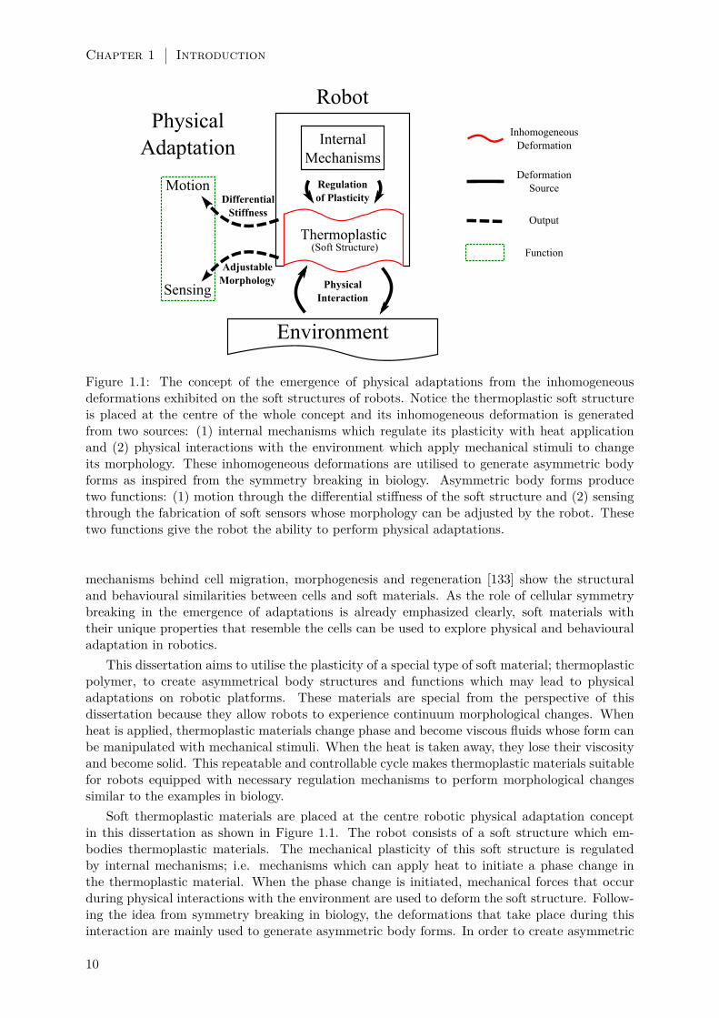
Figure 1.1: The concept of the emergence of physical adaptations from the inhomogeneousdeformations exhibited on the soft structures of robots. Notice the thermoplastic soft structureis placed at the centre of the whole concept and its inhomogeneous deformation is generatedfrom two sources: (1) internal mechanisms which regulate its plasticity with heat applicationand (2) physical interactions with the environment which apply mechanical stimuli to changeits morphology. These inhomogeneous deformations are utilised to generate asymmetric bodyforms as inspired from the symmetry breaking in biology. Asymmetric body forms producetwo functions: (1) motion through the differential stiffness of the soft structure and (2) sensingthrough the fabrication of soft sensors whose morphology can be adjusted by the robot. Thesetwo functions give the robot the ability to perform physical adaptations.
mechanisms behind cell migration, morphogenesis and regeneration [133] show the structuraland behavioural similarities between cells and soft materials. As the role of cellular symmetrybreaking in the emergence of adaptations is already emphasized clearly, soft materials withtheir unique properties that resemble the cells can be used to explore physical and behaviouraladaptation in robotics.
This dissertation aims to utilise the plasticity of a special type of soft material; thermoplasticpolymer, to create asymmetrical body structures and functions which may lead to physicaladaptations on robotic platforms. These materials are special from the perspective of thisdissertation because they allow robots to experience continuum morphological changes. Whenheat is applied, thermoplastic materials change phase and become viscous fluids whose form canbe manipulated with mechanical stimuli. When the heat is taken away, they lose their viscosityand become solid. This repeatable and controllable cycle makes thermoplastic materials suitablefor robots equipped with necessary regulation mechanisms to perform morphological changessimilar to the examples in biology.
Soft thermoplastic materials are placed at the centre robotic physical adaptation conceptin this dissertation as shown in Figure 1.1. The robot consists of a soft structure which em-bodies thermoplastic materials. The mechanical plasticity of this soft structure is regulatedby internal mechanisms; i.e. mechanisms which can apply heat to initiate a phase change inthe thermoplastic material. When the phase change is initiated, mechanical forces that occurduring physical interactions with the environment are used to deform the soft structure. Follow-ing the idea from symmetry breaking in biology, the deformations that take place during thisinteraction are mainly used to generate asymmetric body forms. In order to create asymmetric
10

Inhomogeneous Deformations for Physical Adaptations 1.3
forms, a special type of deformations; inhomogeneous deformations are used in this dissertation.Inhomogeneous deformations take place on a soft structure in a spatially non-uniform manner.This ends up with the break of symmetry in the initial configuration of the soft structure bycreating asymmetric forms. These asymmetric forms are then used as the basis for generatingtwo important functions towards physical adaptation: motion and sensing. Differential stiffness;i.e. the state of having differing mechanical stiffness, of the soft structure creates motion wheninhomogeneous deformations occur. This stiffness difference is either caused by the multi-phase(liquid-solid) state of a single thermoplastic material or the usage of more than one type of softmaterials together in the robot body. Sensing is generated by creating soft structures which aresensitive to the physical changes in the environment. While the inhomogeneous deformationsof thermoplastics are utilised to create sensors with adjustable morphology, the physical inter-actions with the environment are exploited to gather information about changes which occuraround or on the robot body.
This dissertation proposes a four-step systematic analysis towards performing physical adap-tations in robotic platforms. In the first step, the inhomogeneous deformations are defined andexpressed mathematically. In the second step, the two important thermoplastic materials thatare mostly utilised are explained. Next, the mechanisms which maintain inhomogeneous de-formations using thermoplastics and other soft materials are presented. In the last step, themethods of generating motion and sensing functions are shown.
1.3.1 Classification of Deformations
Soft materials play an important role in the achievement of physical adaptation in robots as theyprovide continuum and visco-elastic mediums where deformations can be exhibited in virtuallyinfinite directions. Inspired from symmetry breaking in biology, functionality is related to thecreation of asymmetric body forms in robotic platforms in this dissertation. Theoretically, ifdeformations of soft materials are used to create asymmetric forms, then infinite amount func-tions can emerge which may lead to physical and behavioural adaptations in robotic platforms.However it is not a straightforward process in practice; therefore deformations in continuummaterials should be described first. More importantly, inhomogeneous deformations, which arethe focus of this dissertation, have to be clearly described and distinguished from homogeneousdeformations.
In continuum mechanics, a rigid body displacement consists of the translation and rotation ofa continuum body without any change in its shape and size. In contrast, a deformation suggestsa change in the shape and size of the continuum body. The change of a continuum body’sconfiguration combining rigid body displacement and deformation is called displacement [135].Figure 1.2 shows a continuum body in its initial pre-deformed configuration K0 at time 0. Thisbody undergoes a displacement and results in a deformed configuration Kt at time t. Let Xdenote the position of a small body segment (shown with a blue polygon in Figure 1.1) in thepre-deformed configuration K0 with respect to a fixed reference frame centred at O. After thedisplacement, X ′ shows the position of the deformed segment in configuration Kt.
The mapping function χ takes an initial position X as input and gives the final position X ′of the body segment. If there is no fracture, this mapping function is continuous. Physicallyas each distinct body segment within the continuum body maps into a distinct location, themapping function χ is one-to-one. This relation is written X ′ = χ(X). Then the displacementof this body section will be u = X ′−X with respect to the reference frame with origin O [136].
Given the one-to-one function χ, a deformation is called affine or homogeneous if the relationbetween X and X ′ has the form:
X ′(X, t) = F (t) •X + c(t) (1.1)
where the transforming function F is linear and independent of position, and c is a rigid bodytranslation. As shown in Equation 1.1, homogeneous deformations consist of a linear transfor-
11

Chapter 1 Introduction
Figure 1.2: The deformation of a continuum body explained with the displacement of a cus-tom shaped 3D object from its pre-deformed configuration K0 to its deformed configurationKt. Coloured polygons represent body segments on the continuum body. The position of abody segment (shown in blue) in the pre-deformed configuration X transforms into X ′ afterdeformations which is related with the mapping function χ. The deformation takes place on a2D plane where the height of the object h0 may remain same in ht. Shown deformation relationtakes place in 2D but it can be extended into 3D. Inspired from the illustrations in [134].
mation and a rigid body translation. Shear, scaling (compression and extension) and rotationare examples of linear transformations. For example, rotation is represented as:
X ′(X, t) = R •X (1.2)
where F (t) = R ∈ SO(3)2 in Cartesian coordinates. A single rigid body translation is in theform of:
X ′(X, t) = X + c(t) (1.3)where the transforming function is the identity matrix, F (t) = I, thus allowing the rigid bodyto only translate with respect to the reference frame. In homogeneous deformations, the trans-formation function F applies the same to all body segments in the continuum body. This meansthat every segment in the continuum body experiences the same transformation quantitatively.These deformations preserve a linear relation between all the segments of the initial and deformedconfigurations of the body, either being a transformation or collective translation [134].
In contrast to the homogeneous deformations shown in Equation 1.1, the inhomogeneousdeformations take the following form:
X ′(X, t) = F (X, t) •X + c(X, t). (1.4)
This means that the transforming function F is no longer linear, and it is dependent on bothtime and position of the pre-deformed body segment X. Inhomogeneous deformations can alsobe caused from the position dependent translations c(X, t) as shown in Equation 1.4. In eithercase, inhomogeneous deformations do not preserve a linear relation between the initial anddeformed configurations of the continuum body. For example in homogeneous deformations thelines stay parallel to each other after the deformation; however no such relation is preserved ininhomogeneous deformations. In Figure 1.2, all of the three coloured body segments experienceinhomogeneous deformations.
2SO(3) is the special orthogonal group defined as the group of 3 × 3 orthogonal matrices whose determinantis 1.
12

Inhomogeneous Deformations for Physical Adaptations 1.3
It can be seen that homogeneous deformations preserve a linear relation between body seg-ments within the continuum body. This means that homogeneous deformations will maintainthe symmetries of a continuum body’s initial configuration. In comparison, inhomogeneous de-formations introduce an asymmetric change in the continuum body. As in the formation ofasymmetric body forms in biology, inhomogeneous deformations can convert a symmetric softstructure into a less uniform state with increased directional variance. These types of deforma-tions suggest an important potential to be utilised in the generation of physical adaptations inrobotic platforms and so will be discussed extensively in this dissertation.
In order for a robot to perform physical adaptations, first it must be able to generate newbody morphologies and functions. In this dissertation both of these are founded on the gen-eration of asymmetric forms based on inhomogeneous deformations. For a robot to produceinhomogeneous deformations from a soft body in a controlled manner, a suitable soft materialshould be chosen. After the material is chosen, necessary mechanisms can be designed whichcan initiate the material to undergo desired deformations.
1.3.2 Thermoplastic Materials
In Section 1.1.1, symmetry breaking in the sub-cellular and cellular scale in biology is presentedto reflect how soft structures deform to create asymmetric forms that lead to many importantcell functions. In the creation of their asymmetric configurations, a non-uniform distributionof stimuli is an important key factor. Whether they are chemical, electrical or mechanical, thenon-uniform distribution of these stimuli triggers the cellular structure to undergo inhomoge-neous deformations [19]. As symmetry breaking is taken as an inspiration to generate physicaladaptations in robotic platforms in this dissertation, suitable soft materials should be chosenwhich can undergo inhomogeneous deformations under controlled stimuli.
In this dissertation thermoplastic materials play the key role in generating the functions thatlead to physical adaptations in robotic platforms. Thermoplastics are the types of soft materialswhich become mouldable when a certain temperature threshold is passed. While applying heat,the inner temperature of a thermoplastic material rises and the intermolecular bonding strengthdecreases. This ends up with the material losing its solid structure and becoming a viscousliquid. While the thermoplastic material is in its viscous phase, mechanical stimuli can be usedto mould it into asymmetric forms. The transition from the solid to liquid phase is a repeatableand reversible process. When the heat is taken away from the hot and liquid material, theintermolecular bonds strengthen and the material becomes solid again [137]. The repeatable,heat induced phase changing property of thermoplastic materials make them a convenient choiceas a soft material in order to generate deformation based functions on robotic platforms. If therobot can be equipped with mechanisms which can regulate the deformation of these materialsthrough controlled heat and force application, inhomogeneous deformations can be generated. Inthis dissertation, there are two commonly used thermoplastic materials in the robotic platforms:Hot Melt Adhesive and Conductive Thermoplastic Elastomer.
Hot Melt Adhesive (HMA)
Hot melt adhesives are polymer-based, solvent free thermoplastic materials which can form bondsbetween different solid surfaces in a thermally induced phase change process. HMA generallyconsists of polymers, resin, diluent and wax which in combination give the material its physicalproperties. For example, polymers are responsible for characterising its viscosity, flexibility,and cohesive and adhesive strength. The rest of the ingredients influence HMA’s polymerentanglement, heat and water resistance, and setting speed. The mechanical and rheologicalproperties of HMAs can show difference with respect to the ratio of their ingredients; howeverall HMAs show thermoplastic adhesion features which are based on repeatable and bidirectionalheat induced phase change processes. [138]. The specifications of the HMA used in the robotic
13

Chapter 1 Introduction
platforms presented in this dissertation are given in Table 1.1.
Table 1.1: Specifications of the used HMA ma-terial. Reprinted with the permission of [139].
Density ρ 970kg/m3
Softening point Ts 82− 92CMelting point Tm 170− 200CViscosity µ (160C) 25000− 33000m.Pa.sViscosity µ (180C) 16000− 20000m.Pa.s
Figure 1.3: The relation between the bonding strength and the temperature of the HMA ma-terial. The experimental data collected from the bonding tests with Copper and Aluminiumshow that the bonding strength decreases with the increasing temperature. Dashed lines showthe exponential function which models the bonding strength ratio. The inset plot shows thetemperature range between 40C and 70C. Reprinted with the permission of [139].
HMAs offer a unique thermoplastic adhesion feature which can only be controlled with theapplied heat on the material. Generally HMAs are solid in low temperatures and become low-viscous fluids at higher temperatures (melting temperature is mainly characterised as 82C[138]). Similar to viscosity, HMA’s adhesion capacity and the bonding strength also changewith respect to temperature. The HMA material used in this dissertation has three phasesdepending on its temperature. At the room temperature around 25C, the material is its visco-elastic solid form. At this phase the material is not adhesive; however it has a high bondingstrength. Due to this high bonding strength, if the material is already in connection betweensurfaces, no additional energy is required to maintain the bond. For temperatures around thesoftening point Ts shown in Table 1.1, the bonding strength starts to decrease and the materialstarts to become visco-plastic. When the temperature rises to the melting point threshold Tm(the range is 170−200C), the material turns to a low-viscosity fluid due to the drop of cohesivestrength in between the polymers. However, at this point the liquid material becomes adhesiveand can be moulded into different morphologies and used to adhere to surfaces. Figure 1.3 showsthe relation between the bonding strength and the temperature of the HMA in the experimentsconducted in our laboratory prior to this dissertation [139].
The HMA provides two very important features which are utilised in this dissertation. Thefirst feature is its heat induced repeatable process of thermoplastic regulation. As the reversiblephase change between solid and liquid forms are controlled only with heat induction, this processis used extensively to generate inhomogeneous deformations and create new morphologies. Inorder to form a new morphology, first heat is applied in a non-uniform manner on the HMA
14

Inhomogeneous Deformations for Physical Adaptations 1.3
material. Then the hot liquid part of the structure is manipulated with mechanical stimuli andmoulded into various body forms. The second feature is the thermally induced adhesivenessof the HMA. In this dissertation, HMA’s adhesion is not only used to maintain a continuumbody form during its plasticity regulation but also to from complex shaped bonds between bodymorphologies composed of other soft deformable materials. As the inherent bonding strengthof the HMA does not require additional energy to maintain a bond between surfaces, it is akey element which guarantees the elasticity of multi-material soft structures which undergodeformations without any fracture in this dissertation.
Conductive Thermoplastic Elastomer (CTPE)
Another important thermoplastic utilised in this dissertation is the conductive thermoplasticelastomer. A combination of a thermoplastic elastomer (TPE) and carbon black particles isused in the forming of this material. The CTPE used in this dissertation is produced andprovided by EMPA [140], whose specifications are shown in Table 1.2.
Table 1.2: Specifications of the used CTPEmaterial. Reprinted from [140].
TPE Density ρ 0.89g/cm2
Carbon Black Density ρ 1.8± 0.2g/cm2
Mix Ratio 50wt.−%
As shown in Table 1.2, the TPE and Carbon black particles are mixed with a 50wt.−% ratio.The carbon black ingredient of the material generates a percolated network inside the CTPEwhich results in electrical conductivity throughout the material body. When strain is applied,the percolation network is changing due to rotation of non-spherical carbon black agglomerateswhich are still present in the polymeric matrix. This rotation is reversible and the hybrid materialcan be therefore used for strain sensing in a giant displacement range. That is why the CTPEcan be used to produce strain sensitive soft sensors, whose derivatives can be seen in practicalapplications [119]. Similar to the HMA, CTPE also has thermoplastic properties due its TPEcontent. When heat is applied, CTPE turns into a lower-viscosity fluid which can be mouldedinto different forms. Unlike HMA, CTPE does not have adhesion properties and cannot createbonds between different surfaces. The elastomer ingredient allows the CTPE to be convertedinto liquid and maintain cohesion to remain its continuum form. It also influences CTPE’svisco-elastic property in solid form which makes this material suitable for strain sensitive softsensors which can withstand large deformations.
1.3.3 Mechanisms for Generating of Inhomogeneous Deformations
The next step in the systematic investigation of physical adaptations in robotic platforms is thedesign of mechanisms which will induce inhomogeneous deformations on the chosen soft ther-moplastic materials. As autonomy is crucial towards physical adaptation, the robotic platformsshould be able to operate continuously without human intervention in unstructured environmentsand unplanned situations. Normally the human designer cannot predict all of the possible sce-narios, model the interactions and program robots accordingly. This attempt has been discussedas one of the major limitations to achieving physical and behavioural adaptations in robots inSection 1.2. However, robots can still be equipped with tools, mechanisms and materials so thatthey can autonomously change their body structures either passively or actively to adapt totheir environment. In this sense, as long as a robot can generate inhomogeneous deformationswith its equipment, it can utilise these deformations in the production of motion and sensingfunctions which will reinforce the robot’s autonomous operation performance and enable theemergence of physical adaptation.
15

Chapter 1 Introduction
Figure 1.4: The three mechanisms to generate inhomogeneous deformations using soft materials.With the combination of these mechanisms and physical interactions with environment (shownwith black arrows), soft materials can undergo deformations to yield desired forms and functions.(a) Heat induced regulation of plasticity can convert thermoplastic materials into solid-liquidmulti-phase state which can be moulded into different forms using mechanical stimulus. (b)Structures consisting of multiple soft materials with differing stiffness can react differently touniform stimulus and produce asymmetric forms. (c) The morphologies of soft structures can beadjusted to produce alternative sources of information and functions based on the asymmetricdistribution of internal deformations (shown with red arrows).
In order to design such mechanisms, the soft materials used on the robot should be analysedfor the purpose of generating the functions that lead to the adaptive behaviours. This analysiscovers these materials’ physical properties such as plasticity, mechanical strength (e.g. tensile,shear etc.), viscosity, adhesion and response to various stimuli. Once these properties are mod-elled and confirmed experimentally, it will be possible to design mechanisms that can regulatethese properties to generate inhomogeneous deformations. As shown in the previous section,thermoplastics are used in this dissertation to exhibit the deformations. Here, three differentmechanisms are suggested to induce inhomogeneous deformations on these materials.
1. Heat Induced Regulation of Plasticity: The primary mechanism to induce inhomo-geneous deformations on thermoplastic materials is by regulating their (mechanical) plasticityusing heat induction. This mechanism applies a heat stimulus on the soft structure in a non-uniform manner so that only a particular part of the whole structure’s plasticity is changed.By applying heat on the thermoplastic material, it can be influenced to convert from solidstate to low-viscous liquid state in a repeatable and reversible way. This non-uniform changeof plasticity will yield a multi-state (solid-liquid) condition on the soft structure. Under thiscondition, inhomogeneous deformations can be generated by applying mechanical stimuli tomould the low-viscous part of the structure into different body morphologies. At the end of themoulding process, the heat can be taken away actively with a cooling mechanism or passivelythrough heat convection with the surrounding air. As the main goal is to create asymmetricbody morphologies, this process will yield the desired results as only a certain part of the ther-moplastic structure will experience inhomogeneous deformations. Using the current technology,this mechanism can be designed in different scales which will comply with the available thermo-plastic stock and power input. The concept of this mechanism is shown in Figure 1.4(a). Thethermoplastic material block (shown in grey) is fed into a heat induction mechanism (shown inred) which applies heat only to a certain part of the material. By using mechanical forces whichfeeds the material into the heat cavity and deforms the low-viscous part which comes out, theoverall structure is deformed into an asymmetric form.
2. Differential Stiffness Mediums: Another mechanism to initiate inhomogeneous de-formations is to create a soft deformable structure with an internal medium of differing stiffness.Differential stiffness in a structure means that it has a spatially non-uniformly distributed me-chanical stiffness property along its body. Such a structure exhibits inhomogeneous deformationsunder the influence of a uniform mechanical stimulus which results in asymmetric body forms.Figure 1.4(b) shows the reaction of such a structure to applied internal force. In the figure, the
16

Inhomogeneous Deformations for Physical Adaptations 1.3
structure consists of three different layers: a stiff soft material on the left (dark grey), air pocketin between and a less stiff soft material on the right (light grey). In the case of an internal airpressure supplied from a tube, the stiffer material on the left bends less than compared to themore flexible material on the right. Assuming that there is no fracture and leakage from themedium, the structure deforms into an asymmetric form. One possible method to fabricate thisstructure is to use different soft materials and physically attach them to each other with varioussuitable fabrication methods such as 3D printing, shape deposition manufacturing (SDM) orcasting. In this dissertation, thermoplastic adhesives are used to connect different soft mate-rials together as they can maintain an elastic continuum bond between surfaces under appliedmechanical stress. Another method to create mediums with differential stiffness is to transforma soft material into a multi-phase state with differing visco-elastic properties. This multi-phasestate can be created with regulation of the material’s plasticity as described in the first mecha-nism. In this state, the soft material will have a non-uniform distribution of visco-elasticity andtherefore react differently to applied mechanical stimuli.
3. Adjustable Morphology: The last mechanism to generate inhomogeneous deforma-tions is to design and build soft structures with morphologies which can be adjusted with respectto the stimulus. The morphology (i.e. shape and size) and positioning of a soft structure playimportant roles in how it will react mechanically to stimuli during physical interactions with theenvironment. Based on the interaction physics, the stimuli can cause the soft structure to ex-hibit inhomogeneous deformations which may generate asymmetric forms and functions such assensing or motion. Figure 1.4(c) shows how two different morphologies of a soft structure reactsdifferently to the same physical stimulus. The elliptical soft structure block (shown in grey) isconverted into a beam and a U-shaped arch and placed under a physical stimulus (shown withblack arrows). Both structures are attached to an imaginary wall (shown with white blocks withdashed lines) on different ends. As the structures deform under the same applied stimulus, theyexperience different internal inhomogeneous deformations (shown with red arrows). Such inho-mogeneous deformations do not only create asymmetric forms but also create distinguishablestrain information within soft structures which can be obtained by strain sensitive soft sensors.Distinguishable strain information can be invaluable for soft strain sensors to detect deforma-tions taking place within soft structures. The example in Figure 1.4(c) shows that a single softmaterial can be moulded into different morphologies who can produce alternative sources ofinformation and functions. However, in order for the robot to develop its physical adaptationsbased on these information and functions, it should also be able to adjust the morphology ofits soft structures. That is why adjustable morphology mechanism is dependent on the firsttwo mechanisms of plasticity regulation and differential stiffness. For example, it the robot isequipped with a mechanism which can regulate the plasticity of a thermoplastic material, it canfabricate soft structures with various morphologies which can be actively used by the robot forthe inspection of unknown objects in its environment. Alternatively, the robot can fabricatevarying morphologies of soft structures consisting of different materials which will react differ-ently to stimulus and generate the desired information and functions based on inhomogeneousdeformations.
1.3.4 Generation of Functions from Deformations
The physical adaptation is the structural changes that occur within the body of an organismto adapt to the changes taking place in its environment, as explained in Section 1.1. Based onphysical adaptations, behavioural adaptations are the changes in the behaviours and the actionstaken by the organism to sustain itself. The same arguments can be made for biologicallyinspired robotics. Whether it is biology or robotics, in both of these adaptation types, “change”is the most essential process which incorporates two important functions. This change can eitherbe observed with sensing or executed with motion.
17

Chapter 1 Introduction
Sensing
In means of autonomy and self-assessment, being able to detect and evaluate the changes inthe environment and within the self is very important for successful adaptation. As mentionedin Section 1.1, adaptation related changes occur due to the deformation of soft structures innature. In this dissertation, adaptations in robotic platforms are also based on soft structuredeformations. This means that, in order to observe and assess the adaptation related changeseither in biology and robotics, specialised sensing functions should be developed which cansense deformations of soft structures. Examples to such specialised units which detect softdeformations in biology are given in Section 1.1.2 such as muscle spindles which sense thecontractions within muscle fibres [36]. A similar approach based on deformation sensing shouldbe considered in robotics. If a robot can develop sensing functions based on the deformationsof soft structures, it can evaluate the changes in its environment and the ones taking place onits own body. This may lead to self-organized sensory-motor coordination and decision makingmechanisms both of which will increase the potential of a robot’s physical adaptation capacity.
In the context of this dissertation, sensing function means actively or passively gatheringinformation from directions of inhomogeneous soft structure deformations. This informationgathering is made possible with the knowledge of the deforming soft material’s mechanicalproperties and the usage of deformation sensitive tools as explained in the previous step inSection 1.3.2. This knowledge will allow the robotic system to autonomously associate themagnitude and direction of deformations (e.g. strain or curvature) with changes happening inthe soft body. In order to sense the deformations taking place on the robot’s body, fabricationof sensors with smart soft materials which are responsive to deformations can be useful. Forexample CTPE material can be used to fabricate soft sensors in different morphologies byexploiting its thermoplastic features. These sensors can be placed on the robot body to detectthe changes which occur on robot’s soft deformable body. Alternatively, passive soft structurescan be used as probes to detect the changes in the environment. The robot can probe the objectsin the environment with these soft structures and collect information from their deformations.Deformation information can be gathered either from the embedded sensors on the probe (e.g.CTPE based strain sensors) or from other sensing mechanisms such as cameras which can trackthe deformation of the probe.
Motion
The second important function within adaptation is the motion. Without any doubt, all changeswhich are the part of adaptations are executed by the motion of some or all of the individualbodies inside a complete system. In biology, this motion can be regarded as the movement ofsmall structural units within the body as in cell motility [20] or the movement of limbs or thecomplete organism itself from one place to another such as animal locomotion [38]. While thefirst type of motion can be regarded as the backbone of physical adaptation, the second typecan be related to behavioural adaptations. In either case, motions in biology are dependent onthe continuous movement of the soft structures. In Section 1.2.3 using discrete elements arepresented as a challenge which produces low granularity issues towards achieving physical andbehavioural adaptations in robotics. The molecular elements and the intermolecular bonds whichmaintain continuity even under large deformations make soft materials a suitable candidate togenerate adaptation governing motions in robotics. That is why this dissertation focuses onthe usage of soft materials and their inhomogeneous deformations to generate the two types ofmotion in robots.
Similar to generation of sensing, a prior knowledge about the mechanical properties of thesoft materials is required in order to produce motions from their inhomogeneous deformations.Based on this knowledge, motion can be generated autonomously either by internal mechanismsor through the passive interaction between robot’s soft body and the environment. Heat induced
18

Contributions 1.4
plasticity regulation mechanism is suitable for performing motion of structural units in robotssimilar to cell motility in biology. As thermoplastics go into a phase change under applied heat,the polymer units that make up their general structure can be shifted and relocated with theinfluence of mechanical stimuli. With this mechanism applied on thermoplastics, the motionof structural units is generated and new body morphologies can be formed. The motion of therobot’s components or the robot itself can originate from the elastic deformation of soft structureswith differential stiffness. The inhomogeneous deformation of these multi-material mediums willgenerate an asymmetric distribution of forces acting towards the environment, and make therobot or its components move in certain directions. Similar to the adaptations in biology,the motions generated from the deformation of soft structures will allow the robot’s physicaladaptation through morphological change and behavioural adaptation through movements ofrobot components and robot locomotion.
1.4 Contributions
This dissertation aims to provide researchers a systematic investigation to exhibit physical andbehavioural adaptations on autonomous soft robots. Here, the emergence of adaptations is basedon the formation of asymmetric body forms and functions as a result of inhomogeneous defor-mations of soft materials. Three main contributions are identified and are demonstrated in fourdifferent cases studies which realise the conceptual discussion on the emergence of adaptationsin robots. In all of these contributions, the inhomogeneous deformations of soft materials arecommonly utilised. The first contribution is the regulation of the mechanical plasticity of ther-moplastic materials for the foundation of structural adaptation. The second contribution is theusage of differential stiffness of soft material compositions for the emergence of robot motions.And the last contribution is the sensing of deformations by using adjustable body morphologiesof soft sensor structures.
Based on the three main contributions which are explained in detail below, findings presentedhere provide potential ways to generate robotic functions which allow physical and behaviouraladaptations similar to the examples in biology. Robots having these adaptive functions wouldbe able to demonstrate behaviours which are useful in many application areas such as search andrescue, invasive surgery, rehabilitation and prosthetics, inspection and exploration, and humanmachine interaction. These operations especially require autonomy, flexibility and adaptivitywhich can be achieved with functions which emerge from the inhomogeneous deformations of softmaterials on robotic platforms. Additionally, research fields which aim to understand animallocomotion, neuroscience activities, evolution, and emergent behaviours would benefit from thefindings presented here to develop robots which perform bio-inspired and physically adaptivefunctions in real world experiments.
1.4.1 Regulated Plasticity for Structural Adaptation
In this dissertation, mechanical plasticity plays a very important role in the formation of bodymorphologies and generation of functions which are the basis of the emergence of physical andbehavioural adaptations. Defining the role of plasticity depends on the choice of the soft ma-terials. In this dissertation, a wide range of soft materials are used. However two of these arethe main contributors to the generation of sensing and motion through regulation of plasticity:HMA and CTPE. These materials are both thermoplastics, whose details are already given inSection 1.3.2, which go through a phase change which makes it possible for the robots to makemorphological changes on its own body. .
The first example of plasticity regulation is demonstrated in Chapter 2 with the CTPEmaterial. By utilising its thermoplastic feature, CTPE is extruded from a heated knittingmachine to generate thin and long fibre shaped sensors which are responsive to strain in means
19

Chapter 1 Introduction
of a change in their electrical resistance. In this chapter, different morphologies of these softsensors are created to detect the strain in the inhomogeneous deformations of soft structures.Similar to the CTPE, HMA becomes more viscous and easier to re-shape when heat is applied.Additionally, HMA becomes more adhesive in the viscous state and forms strong bonds withdifferent surfaces when cooled down. In the remaining case studies presented in this dissertation,the thermoplastic and thermoadhesive properties of HMA are utilised for purposes varying frommorphological re-configuration, structural adhesion, sensing to motion. The robotic sensingplatform presented in Chapter 3 makes use of both of HMA’s properties to fabricate soft sensorsand adjust their morphologies to detect the softness and temperature of unknown objects. Themobile robot in Chapter 4 produces its dragline by regulating HMA’s plasticity and relies on itsbonding strength to hang onto this dragline in free space. In this case study, fabrication of thedragline by morphing HMA material also ends up with the emergence of free space locomotionbehaviour. In the last case study presented, HMA is used during the fabrication of the multi-material ligaments of the compliant fingers in Chapter 5. Here, HMA is moulded into complexmorphologies to create continuum adhesive bonds between the soft ligament surfaces of thefinger. The created bond is maintained during the deformation of ligament materials due to thevisco-elastic and adhesive properties of the HMA.
Regulating of plasticity for physical adaptation is one of the major conceptual and technicalcontributions of this dissertation. Unlike MSR robots, this method enables the robotic platformsto exhibit morphological changes in their body structures in a continuum fashion. Robots whichcan autonomously regulate the plasticity of their own soft structures can generate functions thatwill make them more physically adaptive and less dependent on the intervention of humans.This contribution also emphasizes the potential of soft materials in means of helping robotsto realise concepts such as morphogenesis, healing or real world evolution, which are otherwiseunachievable with conventional methods or materials.
1.4.2 Differential Stiffness for the Emergence of Robot Motions
Differential stiffness of multi-material structural compositions is employed by organisms in na-ture to generate adaptive motions from the inhomogeneous deformations. For example, theinfluence of differential stiffness can be observed in the case of ligamentous structure of humanfinger joints which allows the compliant motion of the fingers under applied forces during in-teraction with objects [141]. The adaptation to terrain types and regulation of speed duringtransformation from walking to running are also related to the differing stiffness property ofthe leg muscles of terrestrial animals [142]. Following this concept in biology, this dissertationprovides a systematic investigation on the generation of motion from the inhomogeneous defor-mation of soft materials on robotic platforms. The existence of differential stiffness in a robotbody gives the robot inherent features to generate motions which may lead towards physical andbehavioural adaptations. In this dissertation, the differential stiffness of soft materials are usedas the source of motions that lead to the structural changes of robot bodies, the movement ofrobot components and the locomotion of the entire robotic platform.
In this dissertation, the analysis on the mechanical properties of different soft materialsCTPE, HMA, and several silicones and rubber derivatives (e.g. butyl and nitrile) are provided.By using this analysis, robotic designs are developed where these materials are used in com-bination to create soft body structures with differing stiffness. The understanding of the softmaterial properties also give the robots the ability to autonomously vary the physical state ofthese materials by applying stimuli such as heat and pressure with internal mechanisms. Eitherthrough these mechanisms or interactions with the environment, soft structure with differen-tial stiffness exhibit inhomogeneous deformations. These deformations lead to the emergence ofmotions which are essential towards the physical adaptation of the robot. The spider inspiredmobile robot presented in Chapter 4 uses a heating mechanism to create this differential stiffnessmedium consisting of the multi-phase state of the HMA material. By using the forces from the
20

Structure of the Thesis 1.5
environment (i.e. gravity) and the internal mechanisms, robot deforms this composition into adragline which carries the robot in free space. The spider inspired robot simultaneously movestowards the earth while fabricating the dragline. Similarly, the compliant robot finger jointspresented in Chapter 5 benefits from their multi-material soft ligament joint structures and themotions which arise from their differential stiffness composition. The inhomogeneous deforma-tions of the multi-material ligaments do not only create the motions of the joints but also allowthe robotic fingers to achieve adaptive manipulation by passively conforming to the objects indifferent shapes and sizes.
1.4.3 Sensing of Soft Material Deformations through Adjustable Morphology
Sensing the virtually infinite degrees of freedom of soft material deformations is a fundamentalchallenge for autonomous robots as explained in Section 1.2.3. With the systematic investigationpresented in this dissertation, the inhomogeneous deformations that occur in soft materials canbe used as a source of information and also for the design of sensors to detect the deformationsin multiple directions. By analysing the deformations and using thermoplastic materials such asHMA and CTPE, the case studies in this dissertation demonstrate sensing of the environmentand the self through adjustable morphologies of soft structures.
Case studies presented in Chapter 2 and 3 provide a deeper analysis of the thermoplastic softmaterials which are used during the fabrication of sensors to detect deformations. In Chapter2, the strain sensitive CTPE material is used to fabricate different morphologies of soft sensorsin order to sense twisting and serpentine motions which originate from the inhomogeneousdeformations of the soft body robots. Here, the strain resulting from the asymmetric bodydeformations provide quantitative and qualitative information for strain sensitive CTPE sensorswhich are embedded on the robot body in a continuous fashion. These embedded sensors withvarying morphologies collect this information from the robot body and help to distinguish robotmotions. In Chapter 3, a robotic arm is equipped with a heated extruder mechanism in orderto fabricate soft structures through regulation of HMA’s plasticity. This robot arm producessensors with various morphologies in order to detect the softness and temperature of unknownobjects in the environment. Here, the soft sensors are used as a passive structure and probed ontothe objects with the robotic arm. A mounted camera tracks the inhomogeneous deformationsof these passive probes and evaluates the softness and temperature of the objects.
In both case studies, only the morphology of the sensors are adjusted in order to detectdifferent stimuli. The experiments also demonstrate that the sensitivity and sensing range ofthe soft sensors can also be enhanced by their morphological adjustment. In means of providingrobots with a method to autonomously design, fabricate and use morphologically adjustablesoft sensors, this dissertation also contributes to the emergence of physical and behaviouraladaptations on robotic platforms.
1.5 Structure of the Thesis
In this dissertation, inhomogeneous deformations are utilised for the emergence of physical andbehavioural adaptations which that are based on sensing and motion functions. Case studiespresent robotic platforms which exhibit passive and active sensing, free space locomotion andphysically adaptive manipulation through regulation of soft materials with internal mechanismsand interactions with the environment.
In Chapter 2, the CTPE material is used for the fabrication of sensors that passively detectthe strain originating from the inhomogeneous deformations in soft silicone bodies. This straininformation is employed for the design of the morphology of the sensors which can distinguishcomplex body deformations of soft structures in 3D space [143,144].
In Chapter 3, the perspective of sensing function is changed from passive to active. In the
21

Chapter 1 Introduction
presented approach, the thermoplastic and thermoadhesive properties of the HMA are exploitedto fabricate soft sensors which are actively used by a robotic arm to detect and differentiatedifferent stimuli [145]. In this research, a robotic arm with a heated glue gun extrudes theHMA, and gives directions to the deformable extruded material during the fabrication of twodifferent sensors. Same arm is used to attach these sensors to itself and interact with objects.A camera is used to observe the deformations of the sensors to gather information about thesoftness and temperature of unknown objects.
In Chapter 4, the same HMA material and smaller scale extrusion method are employed tofabricate draglines by a mobile robot to move in free space [146]. Inspired from spiders, this robotextrudes the HMA from a small heated nozzle on its body and regulates its plasticity to forma continuous dragline. With the guidance of gravitational and frictional forces, melted HMAis moulded into a long and continuous line. The robot holds onto this continuously generateddragline while moving towards the ground.
In Chapter 5, a combination of HMA and other soft and elastic materials such as rubberderivatives are used in the design of anthropomorphic joints of robotic fingers [147]. Unlikethe widely used fixed DOF joint mechanisms such as gimbals and hinges, the elastic materialsof the joints work like biological ligaments and allow both stability and structural adaptationduring finger motions. This case study shows the physical adaptation capacity of the soft fingersusing the forces acting in different directions during the interactions between the fingers and theobjects.
22

Chapter 2
Sensorisation of Soft Structuresusing Strain Vectors1
Soft material structures exhibit high deformability and conformability which can be useful formany engineering applications such as robots adapting to unstructured and dynamic environ-ments. That is why we are using soft materials as the source of adaptive functions in therobots presented in this dissertation. However, the fact that they have almost infinite degreesof freedom challenges conventional sensory systems and sensorisation approaches due to the dif-ficulties in adapting to soft structure deformations. In this chapter, we address this challengeby proposing a novel method which designs flexible sensor morphologies to sense soft materialdeformations by using a functional material called conductive thermoplastic elastomer (CTPE).This model-based design method, called Strain Vector Aided Sensorisation of Soft Structures(SVAS3), provides a simulation platform which analyses soft body deformations and automati-cally finds suitable locations for CTPE-based strain gauge sensors to gather strain informationwhich best characterizes the deformation. Our chosen sensor material CTPE exhibits a set ofunique behaviours in terms of strain length electrical conductivity, elasticity, and shape adapt-ability, allowing us to flexibly design sensor morphology that can best capture strain distributionsin a given soft structure. From the perspective of autonomous robots, being able to design sensormorphologies to sense physical deformations of soft structures will give the robots the potentialto assess their adaptation skills without the interference of the human designer. In this chapter,we evaluate the performance of our approach by both simulated and real-world experiments onthe discrimination of deformed body poses and motion patterns and discuss the potential andlimitations.
The work we present in this chapter is the introduction of the adaptive sensing through theinhomogeneous deformations that take place on soft structures. Here we use a special materialcalled CTPE which is a carbon powder and a thermoplastic derivative composite. Thanks to itsthermoplastic nature, structures such as thin fibres can be produced with varying length and
1This chapter presents the collaborative work with my colleagues S.G. Nurzaman and U. Wani under theguidance of F.Clemens and my supervisor F. Iida. I have written the algorithm which designs the morphologiesof soft strain sensors and performed the simulation and physical experiments in addition to the writing of thischapter. U. Wani contributed to this project during his master’s thesis [148]. F. Clemens is a member of theHigh Performance Ceramics Laboratory in EMPA-Zurich, who provided the conductive thermoplastic elastomer(CTPE) material which we used as a strain sensor in our work. F. Clemens, S.G. Nurzaman and F. Iida contributedto the writing and discussions about the two papers which are merged and edited for this chapter which are listedas below:
• U. Culha, S. G. Nurzaman, F. Clemens and F. Iida, “SVAS3: Strain vector aided sensorization of softstructures,” Sensors, vol. 14, no. 7, pp. 12748–12770, 2014.
• U. Culha, U. Wani, S. G. Nurzaman, F. Clemens and F. Iida, “Motion pattern discrimination for softrobots with morphologically flexible sensors,” in Proceedings of IEEE/RSJ International Conference onIntelligent Robots and Systems (IROS), pp. 567–572, 2014.
23

Chapter 2 Sensorisation of Soft Structures using Strain Vectors
diameter. These fibre structures show a linear response to the applied strain on their longitudinalaxis in the form of a change of electrical resistance. In the works we present here we exploitthis property and place these fibres as a variable resistance unit in a simple electronic circuitto measure the change of electrical resistance which represents the amount of strain that thefibre experiences. By this method we are able to use these structures as soft sensors which aresensitive to strain that is generated in the direction of their longitudinal axes.
The inhomogeneous deformations are crucial because they are the main source of the sensors’detectable response. The CTPE sensors we use in this chapter are in the form of long (10-15 cm) and thin fibres with 0.3 mm diameter. The ratio between the length and thickness ofthese fibres make them much more sensitive to strain in their longitudinal axis. Based onthis directional sensitivity feature which emerges from the structure of the sensors, we use theasymmetric deformations on soft structures to maximize the response of our CTPE based strainsensors. When a soft structure deforms, it creates a mesh of strain regions on its surface whichare dependent on the directions of the deformations. These regions can be represented withvectors that show the magnitude and direction of the strain that is dominant in that surface.Based on these surfaces, we can find a pathway which connects the vectors in such a way thata continuous pathway can be formed with the maximum strain magnitude. The morphologyof the pathway is therefore defined by the directions of the strain vectors that are connectedtogether. This means that when the longitudinal axis of the fibre shaped CTPE sensor isplaced in the form of this pathway on the surface of a soft structure, it will generate a largeresponse when the chosen deformation happens. However, as a particular pathway, i.e. sensormorphology, is only defined by a particular deformation, any other deformation fails to causethe sensors to generate a response as large as the chosen deformation. This is the foundation ofthe inhomogeneous deformation based sensor morphology design we present in this chapter forthe purpose of the differentiation of soft deformations. In particular, we show the differentiationof bending, pushing and twisting deformations and serpentine and twisting motions which arethe most common forms of deformations exhibited in soft robotic applications.
We aim to provide a systematic investigation on how physical adaptation can emerge fromdirectional sensing in this chapter. Inspired from biology where sensors are specialized in mor-phology and function to detect specific stimuli, the sensor design method we provide here allowsa robotic system to fabricate specialized sensors through thermoplastic regulation. In this dis-sertation we approach the emergence of physical adaptation from the perspective of body’s rolein generating functions such as sensing and motion. That is why we think soft materials havemore potential in producing deformations which will lead to these functions. For a physicallyadaptive robot with soft body structures, it is substantial to develop a sensing system which willdetect the deformations. The same system is also necessary for a robot to evaluate its adaptationperformance and its relation to its environment. Thus, the sensor morphology design methodwe present in this chapter is useful towards physical adaptation for robotic systems which areable to autonomously fabricate sensors.
From the perspective of this dissertation, this chapter provides working examples to eachof our contributions listed in Chapter 1. In means of differential stiffness, we observe that theCTPE sensors can detect the strain because of the higher stiffness silicone base which forces thesensors to stretch simultaneously with the whole body structure. The differential stiffness is notthe source of motion, but sensing in this case. The fabrication of the sensors is based on thethermoplastic property of the CTPE material which is regulated during extrusion of the sensorfibres. The whole chapter can be regarded as a representation of morphology based sensing, asstrain vector information (magnitude and direction of strain which is dominant in a region) isused to design the sensor morphologies to detect and distinguish soft body deformations.
24

Introduction 2.1
2.1 Introduction
Soft materials are capable of high deformations and conformity to unstructured forms whichmakes them interesting and useful for robotic applications [72, 149]. These soft bodied robotscan flexibly deform and significantly change their shapes to accomplish tasks like locomotion inunstructured environments or manipulation of complex objects. Some examples of the recentachievements in soft robotics research area include a soft gripper capable of picking up unfamiliarobjects with widely varying shape and surface [95], a soft rolling robot inspired by a caterpillar’sability to roll over uneven terrains [96], a robotic arm modeled based on the characteristicmuscles of the octopus [150] and a soft robot capable of squeezing itself through obstacles bychanging its gait pattern [90].
Although soft materials enable complex and rich behaviors, the fact they have an almostinfinite amount of degrees of freedom challenges soft robotics in terms of sensorization of the softbodies to sense the environment or its own spatial configuration. One of the suggested solutionsto evaluate structure curvature was based on external optical sensors [151–155]. However, as it isnot always possible to have a structured environment with external optical sensors like cameras,recently, alternative approaches which relied on embedding sensors in the soft structures havebeen proposed [107]. Mainly driven by tactile sensing [101,102,104] and bio-medical applications[156], there has been important research on soft sensors. While some of these sensors candetect one type of stimulus like multi-axis strain [105, 106], there has been studies which showmultimodal sensing such as pressure and force [108, 109], shear and normal force [110, 111] andstrain and pressure [112].
Despite these highly stimulating works, the role of the size, shape and placement of thesensors, commonly known as sensor morphology, does not seem to have been thoroughly inves-tigated. While the importance of sensor morphology in determining the sensing characteristicsand performance has gained a lot of attention in biology [157,158], embodied intelligence [159],and most recently in robotics [145,160], its role in soft body sensing still remains as a challenge.The sensorization solutions so far have had the potential for enabling customizable sensor mor-phology, but required complex molding and suggested casting processes for integration [101,161]or realized commonly used sensor morphologies [162,163].
In this chapter we propose a technological solution which we call SVAS3 to sensorize soft anddeformable bodies with flexible and easily integrable sensor morphology, as shown in Figure 2.1.The proposed technological solution emphasizes two aspects for soft structure sensorization: theexploitation of strain information within soft deformations for the design of characteristic sensormorphologies and the usage of a soft, elastic and easily customizable strain gauge sensor systemwhich can realize these morphologies. The former aspect depends on the generation of strainwhen a soft structure undergoes deformation. In our method, we can model soft structuresand deformations to extract strain information to localize characteristic strain regions on thestructure surface. These regions are used as a template to design morphologies for flexible straingauge sensors. The latter requires a suitable sensor material which can be used to comply withthe designs generated by our approach. Out of many possible state-of-the-art sensor materialsto fabricate strain sensors like liquid metals [101, 105], carbon or metal coated yarns [114, 115],carbon nano-tube films [116], in our work we have decided to use a specific type of a carbonfiller-containing polymer composite [117–119] because these structures can reach strain lengthsabove 100%. The sensors in this approach are fabricated with a Conductive ThermoplasticMaterial (CTPE), which can be produced quickly and flexibly in terms of shape and size [140].CTPE has thermoplastic properties that enable the fabrication of different sensor morphologieswith simple methods, like heated extrusion or injection moulding, which also allows the sensorsto be quickly integrated into various soft objects in a modular and therefore intrinsically scalableway. The elastic and electrical properties of the fabricated sensors, e.g., linear response over awide range of strain lengths, let us easily model them and estimate their performance throughthe design algorithms in the SVAS3 approach. In this chapter, in order to show the efficacy
25

Chapter 2 Sensorisation of Soft Structures using Strain Vectors
and scalability of our suggested approach, we design sensor morphologies to discriminate finalpostures of soft structures due to bending, twisting and pushing deformations, and evaluatethese designs by integrating CTPE-based strain sensors on physical platforms. We also presenta sample application on a latex glove to discriminate hand signs in order to show that ourmethod can be used in research fields in wearable electronics and smart textiles in addition tosoft robotics.
Figure 2.1: A conceptual schematics of the SVAS3 approach. Three examples of soft bodiesare deformed (shown with red arrows) and sensorised with CTPE-based sensors (shown withblack curves). SVAS3 approach provides a unique sensor morphology that would fit the bestfor each soft deformation. CTPE’s thermoplastic properties allow the fabrication of differentmorphologies and are exploited by the SVAS3 approach in the generation of different sensordesigns. Reprinted from [143].
The remaining structure of this chapter is presented as follows: in Section 2.2, we willintroduce the conductive thermoplastic elastomer material and how it can be fabricated tocreate strain sensors. In Section 2.3, we will introduce the design approach and present itsproperties. In Section 2.4, we will use our suggested method to design sensor morphologies andperform simulation and real world experiments. In Section 2.5 we will evaluate our approach anddiscuss a possible application based on soft body (gloves) with integrated fibre sensor structures.Finally, we will conclude the work and list several relevant future works in Section 2.6.
2.2 Conductive Thermoplastic Elastomer for Strain Sensing
In our approach we use a conductive thermoplastic elastomer (CTPE) developed by EMPA [140]for giant strain sensing, e.g., above 100% reversible strain length. The material is based on acommercial thermoplastic elastomer matrix filled with 50 wt% carbon black powder which makesthis hybrid a candidate for a piezoresistant sensor material. This composition is mixed in a highshear mixer to blend the polymer with the inorganic conductive powder at a temperature of180C. The extracted compound has conductive, thermoplastic and elastic properties which areexploited during fabrication of the sensors, as well as in the sensing mechanism itself.
The carbon black ingredient of the material generates a percolated network inside the CTPEwhich results in electrical conductivity throughout the material body. When strain is applied,the percolation network is changing due to rotation of non-spherical carbon black agglomerateswhich are still present in the polymeric matrix. This rotation is reversible and the hybridmaterial can be therefore used for strain sensing in a giant displacement range. CTPE-basedsensors are only responsive to strain due to this formulation, but their morphology and placementon target structures can enable the sensing of other stimuli as long as a mapping between theapplied stimuli and the strain they generate can be expressed. Additionally, CTPE strain gauges
26
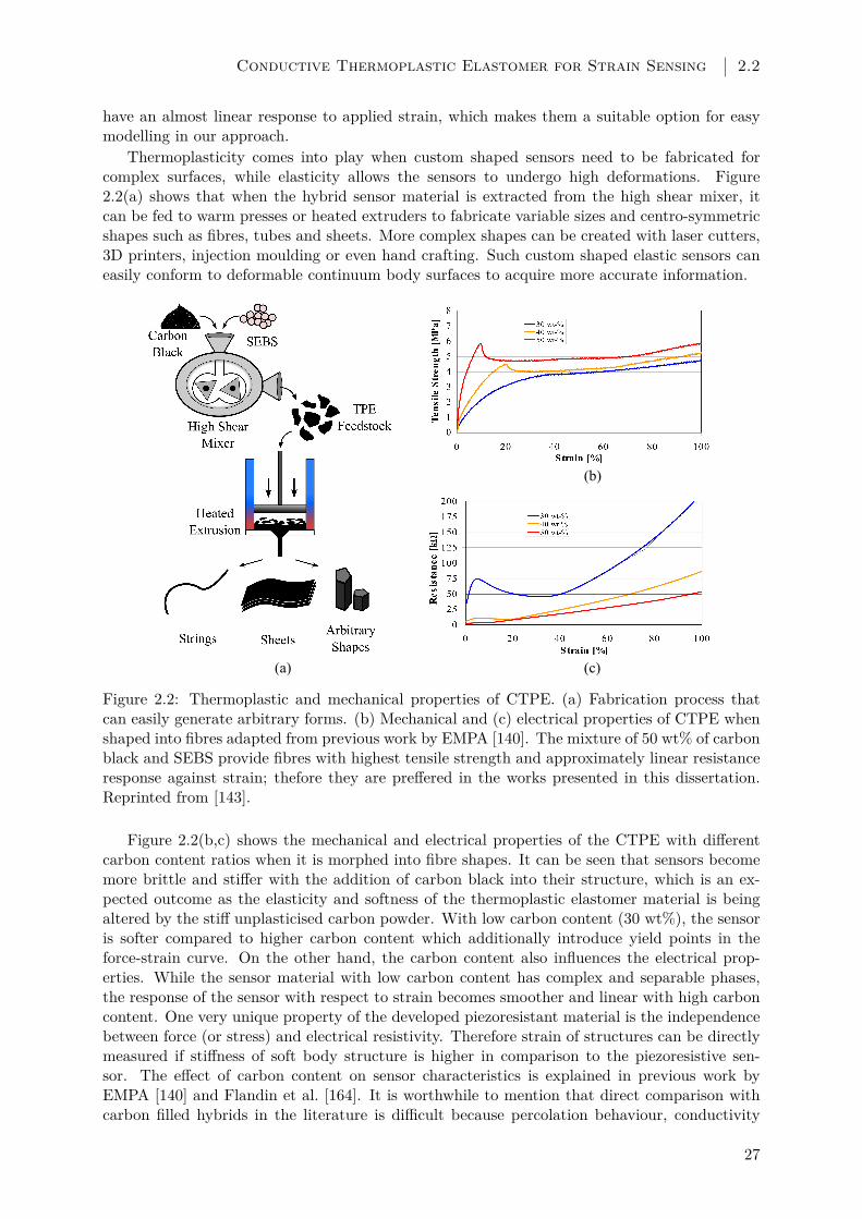
Conductive Thermoplastic Elastomer for Strain Sensing 2.2
have an almost linear response to applied strain, which makes them a suitable option for easymodelling in our approach.
Thermoplasticity comes into play when custom shaped sensors need to be fabricated forcomplex surfaces, while elasticity allows the sensors to undergo high deformations. Figure2.2(a) shows that when the hybrid sensor material is extracted from the high shear mixer, itcan be fed to warm presses or heated extruders to fabricate variable sizes and centro-symmetricshapes such as fibres, tubes and sheets. More complex shapes can be created with laser cutters,3D printers, injection moulding or even hand crafting. Such custom shaped elastic sensors caneasily conform to deformable continuum body surfaces to acquire more accurate information.
(a) (c)
(b)
Figure 2.2: Thermoplastic and mechanical properties of CTPE. (a) Fabrication process thatcan easily generate arbitrary forms. (b) Mechanical and (c) electrical properties of CTPE whenshaped into fibres adapted from previous work by EMPA [140]. The mixture of 50 wt% of carbonblack and SEBS provide fibres with highest tensile strength and approximately linear resistanceresponse against strain; thefore they are preffered in the works presented in this dissertation.Reprinted from [143].
Figure 2.2(b,c) shows the mechanical and electrical properties of the CTPE with differentcarbon content ratios when it is morphed into fibre shapes. It can be seen that sensors becomemore brittle and stiffer with the addition of carbon black into their structure, which is an ex-pected outcome as the elasticity and softness of the thermoplastic elastomer material is beingaltered by the stiff unplasticised carbon powder. With low carbon content (30 wt%), the sensoris softer compared to higher carbon content which additionally introduce yield points in theforce-strain curve. On the other hand, the carbon content also influences the electrical prop-erties. While the sensor material with low carbon content has complex and separable phases,the response of the sensor with respect to strain becomes smoother and linear with high carboncontent. One very unique property of the developed piezoresistant material is the independencebetween force (or stress) and electrical resistivity. Therefore strain of structures can be directlymeasured if stiffness of soft body structure is higher in comparison to the piezoresistive sen-sor. The effect of carbon content on sensor characteristics is explained in previous work byEMPA [140] and Flandin et al. [164]. It is worthwhile to mention that direct comparison withcarbon filled hybrids in the literature is difficult because percolation behaviour, conductivity
27

Chapter 2 Sensorisation of Soft Structures using Strain Vectors
and maximum strain depend on the carbon and the polymeric matrix material.For our approach, we have used a CTPE material with 50 wt% carbon content and the heated
extrusion method to fabricate strain gauge sensors in fibre shape with 0.3 mm diameter. Theresulting fibres had approximately 2 MPa of Young’s modulus, with a base resistivity of 37.5 Ω/mmand showed an almost linear response to strain with an average value of 0.66 kΩ/mm±13%. Inour work we focus on the design of sensor morphologies with desired sensing characteristics,therefore we preferred to concentrate on the electro-mechanical properties of the chosen sensortechnology in simulation models and experiments. Previous work by EMPA covers intensivelyother technical properties of the material and fabricated sensors such as hysteresis (experimentsshow a low hysteresis of 2.25% over 80% strain working range), repeatability, sensor drifting andeffects of long term usage [140,165].
2.3 SVAS3 Design Method
In continuum mechanics, when a force is applied to a solid material it undergoes a deformation,whose mechanical properties can be analyzed with the relationship between the stress in thebody that the force causes and the strain that occurs during the deformation of the body [166].In classical terms, this relation can be expressed with Hooke’s Law:
σ = F/A = Eε, (2.1)
where the stress σ is generated by the force F on a cross section of A on the material. Theresulting strain ε is dependent on the elastic properties of the material, and can be dictated byits Young’s modulus E, as long as the material shows elastic and reversible deformation whilethe applied stress is below the yield stress.
Deformations in soft bodies can also be explained by the same formula as long as the structuredoes not exhibit plastic deformations. Following this idea, we hypothesize that for every complexdeformation, there exists a unique and representative strain information. In our approach, we usethis strain information and its geometric properties to design morphologies for flexible sensorswhich are responsive to strain. Sensor morphologies are designed by following five consecutivesteps: (1) soft body and elastic deformation modelling; (2) strain vector extraction; (3) strainregion clustering and (4) path planning for final morphology formation. These four steps end upwith a final strain path where fibre shaped sensors, which are fabricated with CTPE material,can be placed on to gather strain information and estimate the sensor response to the selecteddeformations.
2.3.1 Soft Body Modelling
The overall approach starts with the modeling of the soft structure and the deformations thatgenerate the strain information which will be used to construct the final sensor morphology. Formodeling, we are using an open source platform called VoxCad [167] that provides a compu-tationally efficient simulation environment for soft structures. In VoxCad, a mesh of discrete3D pixels, i.e., voxels, which are connected to each other with spring damper systems, are usedto construct larger complex soft structures. These voxels can be given configurable materialproperties such as elasticity, density and thermal expansion, which allow the definition of thestatics and dynamics behaviours of the final objects. The dynamics and non-linear complex de-formations of these structures can be simulated by the usage of external forces and constraints.Constraints such as self-collisions or anchoring points enable the computation of complex pos-tures due to large deformations and interactions between several objects.
In Figure 2.3(a), a prismatic block consisting of three layers with each layer having a 450voxels; 30 × 15 (x × y), is constructed. After structure modelling, additional forces and con-straints are applied to generate a final deformation. Figure 2.3(b) shows the example block as
28

SVAS3 Design Method 2.3
fixed to the ground on both short ends (green rectangles), and a block of force is applied in thepositive y direction (purple prism). Depending on the material properties of the soft structureand the mechanical stimulus range, VoxCad calculates the final posture of the object as shownin Figure 2.3(c) with a color coding where lighter colors represent higher magnitudes of positivestrain. In our approach, we divide the selected mechanical stimulus range into seven equal stepsand generate final postures of the objects for each step. These consecutive postures are collectedtogether to form a complete set for the whole stimulus range.
(a) (b) (c)
(d) (e)
Figure 2.3: Overall process of SVAS3 explained with an example soft structure block. (a) Softbody constructed with voxels, (b) constraints and stimulus applied and (c) soft body deformationsimulated. (d) Strain vectors are extracted from deformations and (e) clustered to generate thefinal sensor morphology. Higher strain magnitudes are represented with warmer colours in (c).Components of a strain vector is given in detail in (d). Generated strain clusters are representedwith different coloured circles in (e). Reprinted from [143].
2.3.2 Strain Vector Extraction
We developed a plug-in for VoxCad in order to extract the strain information of every voxel ina vector form, which we call “strain vectors”. For a soft structure model consisting of n voxels,the strain vector if the ith voxel, Vi, has the following format:
Vi = [sx, sy, sz, px, py, pz] (2.2)
where s is the magnitude of strain and p is the position of the voxel in three axes. Therefore,the final posture of a soft structure due to a selected deformation generates a strain matrix ofsize n × 6. Figure 2.3(d) shows the resulting strain vectors on the topmost layer of the block inthe given example. In the detail, the position of a vector and its magnitude in the x-y directioncan be seen as well. In our approach a complete deformation set is represented with consecutiveseven steps which eventually generate a strain matrix of size 7 × n × 6 which is denoted as M.
2.3.3 Localization of Strain Regions
After the strain matrix is generated, the strain vectors in this matrix are analysed to localize thecharacteristic strain regions of the deformation. In our method, we concentrate on the surfacelayer of the whole structure to comply with easy sensor attachment. Voxels on the surface layeris found by analysing their “pz” value. This reduces the size of the multidimensional strainmatrix into |M ′| = 7×m×6, where m = n/q and q is the number of layers in the soft structure.In order to find characteristic regions on this topmost layer, direction information of the strainvectors are used. For every strain vector in the reduced matrix M ′, the angle of strain directionin the x-y plane, i.e., θi, is found by:
29

Chapter 2 Sensorisation of Soft Structures using Strain Vectors
θi = arctan(py/px) (2.3)whose physical explanation can be seen in the detail of Figure 2.3(d). The resulting matrix
with size 7×m contains the angle information of every strain vector in all of the seven steps of thedeformation. This matrix is then given as an input to MATLAB’s K-means clustering tool [168]which uses a similar algorithm that was originally suggested [169]. The main idea behind thisclustering method is to find a “k” number of discrete clusters, i.e., S∗ = S1, S2, . . . Sk, withina larger set, that are distinct from each other with respect to a defined set of properties:
S∗ = arg mink∑i=1
∑θi∈Si
‖θj − µi‖2 (2.4)
Equation 2.4 shows the general approach of finding this discrete cluster set S∗, where k isthe number of clusters, θj is the angle of strain, and µi is the average of points, i.e., average ofstrain angles, in Si. However, when only θ is used to generate the cluster set S∗, it is possiblethat voxels belonging to a single cluster can be physically separated from each other by differentvoxels. That is why, in order to generate distinct regions in means of physical location and strainangle, we divide the cluster set S∗ into groups called “strain regions”, i.e., Ri, and generate aregion set R = R1, R2, . . . Rl where l ≥ k.
As explained in Algorithm 1, when the physical locations of voxel groups are taken intoconsideration in addition to θ, a larger region set R is formed. This set is composed of Ri, whichis a 7 × m matrix that represents the set of voxels that are physically next to each other andmembers of the same Si. Final representation of these strain regions can be seen in Figure 2.3with different coloured groups.
Algorithm 1: Strain region generation algorithm. Adapted from [143].Data: cluster set S∗, reduced matrix M’Result: region set Rforall the deformation step in M’ (1 to 7) do
forall the voxel Vi in M’ (i = 1tom ) docheck all physical neighbours of Vi;if neighbour Vj ∈ Si then
make neighbour Vj ∈ Ri;else
make neighbour Vj ∈ Rj ;
When strain regions are localized, we use their geometric properties to design the morpholo-gies for strain sensors. Because of the fact that the strain sensors we use in this work are fibreshaped, we start this task by conceptualizing the strain regions as template lines. As every strainregion can be considered as a polygon which consists of several voxels whose strain vectors’ angleare very similar to each other, each of these regions can also be represented by a single line whichspans across the polygon with a slope of that region’s average strain angle. In order to find themiddle point of that line, we calculate the centroid point of a single strain region Ri as:
Si =px1,y1 + px2,y2 + · · ·+ pxr,yr
r(2.5)
where px,y represents the x,y positions of each voxel in the region Ri with size r. For simplicitywe omit the regions whose |Ri| < 3 and centroid point is located out of its polygon. After that,we find the average strain magnitude in that region as follows:
Mi =r∑j=1
√s2xj + s2
yj
r(2.6)
30

SVAS3 Design Method 2.3
Mi is used as a scaling factor to find the longest possible straight line that crosses the Cipoint. For simplicity we omit those regions whose Mi < 0.05 mm as the strain will be weakerthan detectable values. Eventually every region Ri results in forming a line li, which represents asuitable sensing location in that region, with length Li, and slope the same with region’s averagestrain direction angle.
2.3.4 Sensor Pathway Planning
At this point of the approach, we have a set of regions Ri and a set of lines li, which represent asuitable sensor location for every region. We hypothesize that a final pathway which is a resultof the connection of a combination of these lines will yield the morphology of a strain sensor thatcan distinctively represent that soft structure’s deformation. Therefore, we use a path planningalgorithm which connects these lines by using a cost function to determine the final pathway forthe sensors. We define the cost function for any voxel with a position [px, py] on the topmostlayer, to be connected to the representative region line li of any Ri as:
f(i) = d/(Li ∗Mi) (2.7)
where d is the Euclidean distance between that voxel and the closest point on the region lineli. Equation 2.7 basically suggests that any line with high strain magnitude or length will yielda lower cost, and therefore will be preferred in the path planning algorithm.
Our path planning algorithm starts with the initialization of the end points of the final sensorpathway. When these points are defined, the algorithm basically searches every possible l tofind a final pathway that connects the start point to the end point with minimum cost withrespect to the cost function. As shown in Algorithm 2, the algorithm starts on the start pointand moves towards the end point by connecting the lines together until either there are no morepossible lines in front of it or the end point is reached. When either of these situations holds,the algorithm finalizes the set PW which basically consists of the geometric information aboutthe chosen lines.
Algorithm 2: Weighted cost path planning algorithm. Adapted from [143].Data: region set R and lines lResult: final pathway PWinitialize points [start, end] on the surface;set current point P to [start];while R 6= ∅ or P 6= [start] do
check all Ri in R;find Ri with min f(i);add Ri to PW;update P with end point of l of Ri;remove Ri from R;
When the lines in the PW set selected by Algorithm 2 are connected to each other, the finalpathway is determined. This pathway consists of two major parts; region lines l, as in PW, andstraight connection lines which connect them together. While the strain information presentedby region lines are true and shows the characteristics of selected regions, connection lines mightproduce erroneous strain information as they can go through several regions by ignoring straindirection angles. This classification enables us to emphasize true strain information duringsensor output estimation. The resulting shape of the final pathway can be seen in Figure 2.3(e),where region lines are shown with complete lines and connection lines are shown with dashedlines.
31

Chapter 2 Sensorisation of Soft Structures using Strain Vectors
2.3.5 Sensor Modelling
The pathway can be considered as the final form for sensor morphology, as we are using thin,fibre shaped strain gauge sensors which could be laid directly on this pathway. Therefore, alsoconsidering CTPE’s elastic properties and linear response to applied strain, we can use the straininformation collected from this pathway as a mean to estimate sensor output O as:
O = LPW ∗KB +N ∗Wr ∗KS +Wc ∗KS (2.8)
where LPW is the total length of the pathway, Wr and Wc are the total strain magnitudesgathered from the region and connection lines by using Equation 2.6, KB and KS are the baseresistance and sensitivity values for CTPE-based fibre shaped sensors as explained in Section2.2. Due to the line classification explained earlier, we can enhance the true strain response bysimply multiplying by N, which physically means to add N-1 lines in parallel with that originalregion line. Although it is possible to detect positive and negative strain with CTPE-basedstrain gauge sensors when they are integrated into structures with a pre-stretch [140], in ourwork we choose to integrate these sensors with their resting form which allows us to detect onlypositive strain. Therefore, in the sensor modelling part we only use positive strains to ensurecorrect sensor output.
2.4 Experiments
In this section, we perform two sets of experiments in simulation and physical platforms todiscover the efficacy of our suggested method. The first set focuses on the discrimination ofthree soft deformations ; i.e., bending, twisting and pushing in Section 2.4.1. As a first step,these deformations are generated once per test, instead of a repeated pattern, to show theefficacy of our method. In order to perform discrimination, sensor morphologies are designedand evaluated by experiments in both simulation and physical platforms. Firstly, simulationexperiments are performed to show the scalability of the method on various shapes of softstructures, given the current state of path planning and sensor placement algorithms explainedin Section 2.3. Secondly, experiments on physical platforms are performed to compare withsimulation results for the investigation of simulation limitations such single-material physics,linear elasticity assumption and limited data point collection.
In the second set which is explained in Section 2.4.2, we extend the experiments to test ourapproach on repeated soft deformations, which can also be regarded as soft behaviours. We picktwo of the most commonly practised behaviours in soft robotics field; namely serpentine andtwisting. We use the same approach to generate the sensor morphologies; however to increasethe sensor output difference between two sensors, we perform an additional vectoral subtractionduring the sensor design steps. The generated sensor morphologies are tested in both simulationand physical experiments to show the outreach of our approach to the robotics field.
2.4.1 Discrimination of Single Deformations
Simulation Results
We start by modelling three different shapes aiming to show the scalability of the general ap-proach given the current path planning algorithms. For this purpose we have chosen a circle,a plus and a square forms for simulated soft structure models. For fair comparison, similarsizes are chosen: all of the soft structures have three layers of voxel surfaces, with each voxelhaving a cubic shape of 1.5 mm in size, while the square and plus having 45 voxels on each sideand circle having 45 voxels on its diameter. The structures are given linear elastic propertiesand constructed with the material properties of Silicone with a Young’s modulus of 1.31 MPa.Each of these structures has undergone three different deformations, i.e., bend, twist and push.
32
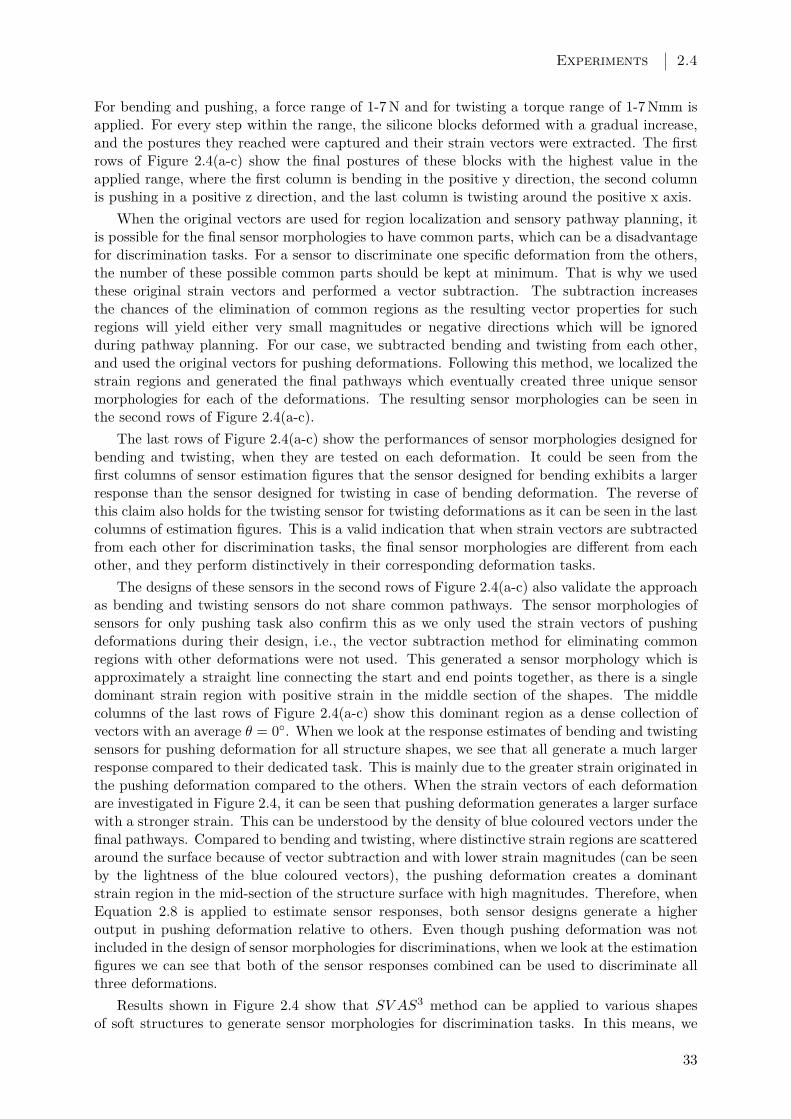
Experiments 2.4
For bending and pushing, a force range of 1-7 N and for twisting a torque range of 1-7 Nmm isapplied. For every step within the range, the silicone blocks deformed with a gradual increase,and the postures they reached were captured and their strain vectors were extracted. The firstrows of Figure 2.4(a-c) show the final postures of these blocks with the highest value in theapplied range, where the first column is bending in the positive y direction, the second columnis pushing in a positive z direction, and the last column is twisting around the positive x axis.
When the original vectors are used for region localization and sensory pathway planning, itis possible for the final sensor morphologies to have common parts, which can be a disadvantagefor discrimination tasks. For a sensor to discriminate one specific deformation from the others,the number of these possible common parts should be kept at minimum. That is why we usedthese original strain vectors and performed a vector subtraction. The subtraction increasesthe chances of the elimination of common regions as the resulting vector properties for suchregions will yield either very small magnitudes or negative directions which will be ignoredduring pathway planning. For our case, we subtracted bending and twisting from each other,and used the original vectors for pushing deformations. Following this method, we localized thestrain regions and generated the final pathways which eventually created three unique sensormorphologies for each of the deformations. The resulting sensor morphologies can be seen inthe second rows of Figure 2.4(a-c).
The last rows of Figure 2.4(a-c) show the performances of sensor morphologies designed forbending and twisting, when they are tested on each deformation. It could be seen from thefirst columns of sensor estimation figures that the sensor designed for bending exhibits a largerresponse than the sensor designed for twisting in case of bending deformation. The reverse ofthis claim also holds for the twisting sensor for twisting deformations as it can be seen in the lastcolumns of estimation figures. This is a valid indication that when strain vectors are subtractedfrom each other for discrimination tasks, the final sensor morphologies are different from eachother, and they perform distinctively in their corresponding deformation tasks.
The designs of these sensors in the second rows of Figure 2.4(a-c) also validate the approachas bending and twisting sensors do not share common pathways. The sensor morphologies ofsensors for only pushing task also confirm this as we only used the strain vectors of pushingdeformations during their design, i.e., the vector subtraction method for eliminating commonregions with other deformations were not used. This generated a sensor morphology which isapproximately a straight line connecting the start and end points together, as there is a singledominant strain region with positive strain in the middle section of the shapes. The middlecolumns of the last rows of Figure 2.4(a-c) show this dominant region as a dense collection ofvectors with an average θ = 0. When we look at the response estimates of bending and twistingsensors for pushing deformation for all structure shapes, we see that all generate a much largerresponse compared to their dedicated task. This is mainly due to the greater strain originated inthe pushing deformation compared to the others. When the strain vectors of each deformationare investigated in Figure 2.4, it can be seen that pushing deformation generates a larger surfacewith a stronger strain. This can be understood by the density of blue coloured vectors under thefinal pathways. Compared to bending and twisting, where distinctive strain regions are scatteredaround the surface because of vector subtraction and with lower strain magnitudes (can be seenby the lightness of the blue coloured vectors), the pushing deformation creates a dominantstrain region in the mid-section of the structure surface with high magnitudes. Therefore, whenEquation 2.8 is applied to estimate sensor responses, both sensor designs generate a higheroutput in pushing deformation relative to others. Even though pushing deformation was notincluded in the design of sensor morphologies for discriminations, when we look at the estimationfigures we can see that both of the sensor responses combined can be used to discriminate allthree deformations.
Results shown in Figure 2.4 show that SV AS3 method can be applied to various shapesof soft structures to generate sensor morphologies for discrimination tasks. In this means, we
33
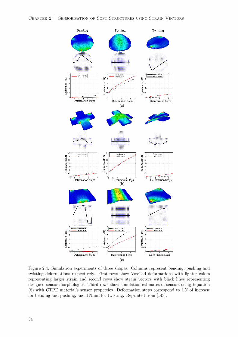
Chapter 2 Sensorisation of Soft Structures using Strain Vectors
(a)
(b)
(c)
Figure 2.4: Simulation experiments of three shapes. Columns represent bending, pushing andtwisting deformations respectively. First rows show VoxCad deformations with lighter colorsrepresenting larger strain and second rows show strain vectors with black lines representingdesigned sensor morphologies. Third rows show simulation estimates of sensors using Equation(8) with CTPE material’s sensor properties. Deformation steps correspond to 1 N of increasefor bending and pushing, and 1 Nmm for twisting. Reprinted from [143].
34

Experiments 2.4
can claim that our method is scalable to different structure shapes as long as the used sensorlocalization and path planning algorithms explained in Section 2.3 are given.
Experiments on Physical Platforms
While simulations only can show that SV AS3 method can generate sensor morphologies andestimate the sensor performances, the influence of limitations on single-material physics, linearelastics assumptions and limited number of data points need to be explored by physical experi-ments. For the validation and evaluation of these aspects, we performed two sets of experimentson physical platforms following simulations and tested the designed sensors. In the first set,the deformation scenarios in the simulations explained in Section 2.4.1 are tested to evaluatethe applicability of the design method and the scalability on different structure shapes. In thesecond set, the effect of single material physics and other simulation parameters such as linemultiplication is evaluated on a rectangular silicone block.
In order to validate the performance of designed sensor morphologies in the earlier simula-tions, we moulded several silicone (Mold Max®40 Series, E = 1.31 MPa) blocks with the samesize in the 3D models. We built silicone blocks with the shape of circle, plus and square forthe first experiment set, and rectangular blocks for the second set. Then we fixed fibre shapedCTPE-based strain gauge sensors on the silicone blocks by following the designed pathways.In order to place the sensor fibres accurately on the guidelines with no slack, we used steelpins as anchor points on the silicone and attached these sensors to the silicone block surfaceswith a high elasticity transparent silicone glue (Dow Corning 732). Figure 2.5(a) shows theintegration process for the second experiment set where CTPE-based sensors are stretched overthe rectangular silicone block by anchor pins and then attached to the surface with the siliconepaste.
(a) (b) (c)
Figure 2.5: (a) The integration step of CTPE-based strain sensors on the moulded siliconeblocks. CTPE sensor fibres are placed on the surface with the guidance of anchor pins whichreduce slack to the minimum. A silicone paste is used to attach the fibres to the silicone surfaceand pins are removed after the paste is cured. The designed and realized sensor morphologiesare shown for bending (b) and twisting (c). Reprinted from [143].
To induce deformations for bending, twisting and pushing, we constructed three differentexperimental setups as shown in Figure 2.6. For bending, a clamping mechanism is created tofix both ends of the silicone blocks to the ground. Another clamp is attached to the centre of thesilicone block and connected to a servo motor which produces linear force in positive y direction.A linear force gauge is placed in series within this connection to measure the applied force.
A similar setup is used for pushing, only for the exception that the force was applied in thepositive z direction. For the twisting, a clamp is attached to fix one end of the silicone block. Theother end is attached directly to a servo motor shaft to generate torque. Total amount of twistangle is measured with an angle compass and values are mapped into torque. The forces andtorques are applied continuously with an increase of 1 N and 1 Nmm every 0.5 s. In all setups,CTPE sensors are connected to a simple voltage divider circuit, whose output is processed withan Arduino Due®microprocessor. Figure 2.6 shows setups for both experiment sets.
The first set of experiments investigates the applicability of the design method on physical
35

Chapter 2 Sensorisation of Soft Structures using Strain Vectors
Clamps
Servo
Motor
Force
Gauge
(a) (b) (c)
Figure 2.6: Experimental setups which generate strain on the silicone blocks to create deforma-tions of (a) bending, (b) twisting and (c) pushing. Clamps make sure that silicone block onlymoves in targeted axes (shown with red arrows) due to the actuation provided by servo motors.Force gauges monitor the force and torque generated due to the deformations. The silicone blockin (a) to (c) is embedded with the same sensor design which is optimised only for twisting. Thissetup aims to show the performance of each sensor morphology for every deformation. Adaptedfrom [143].
platforms and its scalability on various structure shapes. Figure 2.7 shows the experimental re-sults done with the sensor designs provided in simulations in Section 2.4.1. It can be seen fromthe figure that the quality of the sensor performances follows the simulation estimates in Figure2.4. In other words, the sensors designed for their corresponding deformation; i.e., bend sensorfor bending deformation, generate a larger respond than the other sensor when that particulardeformation is applied. The experiments not only suggest that the proposed design methodologyfor sensor morphologies can be applicable in real world, but also show that the designed sensorscan be applied to various structure shapes as suggested by the simulations. In compliance withthe simulation estimates, the first set of experiments also show that when a certain deformationis not considered as a contributing factor during the sensor design, the generated sensor mor-phologies’ performances on these deformations cannot be predicted or programmed. This resultcan be seen in both simulation and experimental results when the performances of bend andtwist sensors are investigated in pushing deformations.
While the first set of experiments support the general applicability of the sensor designs, anadditional set of experiments were required to investigate the impact of single material physicsand line multiplication parameters of the simulations on physical implementations. For thisreason we generated a similar simulation scenario to test these factors. Here, we started withsimulating a prismatic block similar to Figure 2.4(c) which is composed of three layers with1800 voxels; 60 × 30 (x × y), in each layer. Every voxel is cubic shaped with a side lengthof 1.5 mm, making the size of the complete block as 90 mm × 45 mm × 4.5 mm. In order toinvestigate the material effect, the block is simulated with two different materials with linearelastic properties and Young’s modulus of 1.31 MPa and 2 MPa. Additionally, the characteristicregion lines, as explained in Equation 2.8, on the sensor morphologies are multiplied with 3 toenhance the sensor response. We have applied the same force ranges as in the previous section,generated the exact same deformations and designed two sensor morphologies.
We can see that the experimental result in Figure 2.8(c) follows the trend suggested in thesimulation estimates qualitatively in Figure 2.8(a-b). Sensor 1, which was designed for bending
36

Experiments 2.4
(a)
(b)
(c)
Figure 2.7: Experimental results of designed sensors for bending and twisting deformations ondifferent structure shapes. In every shape, two sensor designs; i.e., bend and twist sensors, aretested for three deformations. While each row shows the experiments on structure shapes, everycolumn shows the deformation type. Experimental setup provides steps of stimulus increase forevery 0.5 s during deformations; 1 N for bending and pushing, and 1 Nmm for twisting. Reprintedfrom [143].
deformation outperforms Sensor 2 in bending, while the reverse of this case hold for Sensor2, which was designed for twisting, in twisting deformation. Additionally, both of the sensorsgenerate a larger response in pushing deformation as suggested by the simulation. In order toensure that twisting and bending can be detected by these sensor designs, we have run additionalexperiments and showed that sensor responses are significantly different. We repeated each ofthe deformations five times and collected the average peak values of Sensor 1 and 2 responsesin bending and twisting experiments. For the bending tests, Sensor 1 had an average peakresponse of 0.688±0.019 kΩ and Sensor 2 had 0.263±0.008 kΩ, whose difference yields a p valueof 7.61×10⁻⁷ in a standard t-test for statistical significance. Similarly, for the twisting testsSensor 1 had an average peak response of 0.365±0.027 kΩ and Sensor 2 had 0.682±0.004 kΩwhose difference yields a p-value of 1.26×10⁻⁵. As both of these final p-values are lower than0.01, the experiments show that the designed sensor morphologies for the specified task canachieve successful discrimination.
37
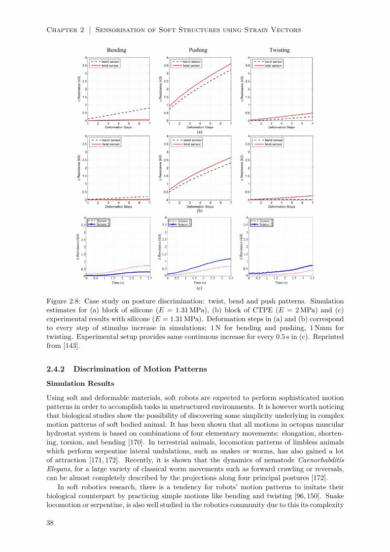
Chapter 2 Sensorisation of Soft Structures using Strain Vectors
(a)
(c)
Figure 2.8: Case study on posture discrimination: twist, bend and push patterns. Simulationestimates for (a) block of silicone (E = 1.31 MPa), (b) block of CTPE (E = 2 MPa) and (c)experimental results with silicone (E = 1.31 MPa). Deformation steps in (a) and (b) correspondto every step of stimulus increase in simulations; 1 N for bending and pushing, 1 Nmm fortwisting. Experimental setup provides same continuous increase for every 0.5 s in (c). Reprintedfrom [143].
2.4.2 Discrimination of Motion Patterns
Simulation Results
Using soft and deformable materials, soft robots are expected to perform sophisticated motionpatterns in order to accomplish tasks in unstructured environments. It is however worth noticingthat biological studies show the possibility of discovering some simplicity underlying in complexmotion patterns of soft bodied animal. It has been shown that all motions in octopus muscularhydrostat system is based on combinations of four elementary movements: elongation, shorten-ing, torsion, and bending [170]. In terrestrial animals, locomotion patterns of limbless animalswhich perform serpentine lateral undulations, such as snakes or worms, has also gained a lotof attraction [171, 172]. Recently, it is shown that the dynamics of nematode CaenorhabditisElegans, for a large variety of classical worm movements such as forward crawling or reversals,can be almost completely described by the projections along four principal postures [172].
In soft robotics research, there is a tendency for robots’ motion patterns to imitate theirbiological counterpart by practicing simple motions like bending and twisting [96, 150]. Snakelocomotion or serpentine, is also well studied in the robotics community due to this its complexity
38

Experiments 2.4
Figure 2.9: Drawings of some animals performing soft deformations during their complex mo-tions;(a) serpentine and (b) twisting patterns are represented with simpler soft elastic deforma-tions. SVAS3 is applied for these two deformations to yield the final sensor morphologies forboth behaviours in (c) and (d). An additional vectoral subtraction is implemented to finalizethe sensor pathways which are shown with strong black lines. Adapted from [144], © 2014 IEEE.
[173]. Therefore, in this work, we focus on discriminating two widely used motion patternsillustrated by Figure 2.9 (a) serpentine (snake-like) and (b) twisting.
(a) (b) (c) (d)
0 2 4 6 80
0.5
1
1.5Sensor 1
Deformation Steps
Sen
sor
Res
po
nse
(kΩ
)
serpentine
twist
0 2 4 6 80
0.5
1
1.5Sensor 2
Deformation Steps
Sen
sor
Res
po
nse
(kΩ
)
serpentine
twist
0 2 4 6 80
0.5
1
1.5Sensor 1
Deformation Steps
Sen
sor
Res
po
nse
(kΩ
)
serpentine
twist
0 2 4 6 80
0.5
1
1.5Sensor 2
Deformation Steps
Sen
sor
Res
po
nse
(kΩ
)
serpentine
twist
Figure 2.10: Simulation results of sensor responses to motion patterns with different line repe-titions depicted with N . While (a) and (b) show sensor outputs with N = 1, (c) and (d) showthe increased response due to line multiplication where N = 3. Every deformation step corre-sponds to 1 Nmm and 1 N increase for twisting and serpentine patterns respectively. Reprintedfrom [144], © 2014 IEEE.
In this section we wanted to design different sensor morphologies to discriminate serpentineand twisting patterns from each other. In order to achieve that, we used an additional vectorsubtraction between strain vectors of each deformation to ensure the elimination of commonstrain regions. The remaining regions generated pathways that are different from each otherwhich ended up with sensor morphologies that are more sensitive to their corresponding motionpattern. The generated sensor morphologies, black lines in the last row of Figure 2.9(c) and(d), also show the exclusion of common pathways. When sensor outputs are estimated withEquation (2.8) as shown in Figure 2.10, it can be seen that Sensor 1(serpentine sensor) andSensor 2(twisting sensor) performs better compared to each other during their dedicated motionpattern.
39

Chapter 2 Sensorisation of Soft Structures using Strain Vectors
Experimental Results
In order to validate the performance of designed sensor morphologies, we have moulded 2 silicone(Mold Max®40 Series, E = 1.31 MPa) blocks with the same size in the 3D models. Then we haveplaced fibre shaped CTPE based gauge sensors on the silicones block by following the generatedpathways. In order to place the sensor fibres accurately on the guidelines with no slack, we haveused steel pins as anchor points on the silicone and attached these sensors to the silicone blocksurfaces with a high elasticity transparent silicone glue (Dow Corning 732). Figure 2.11 showsthe final format of the silicone blocks and integrated sensors.
CTPE
Sensors
Silicone
BlocksSilicone
Paste
Copper
Cables
Knots
Figure 2.11: Final form of the silicone blocks and integrated sensors for detecting serpentine(top) and twisting (bottom) motion patterns. Notice that lines over true strain regions aretripled to increase overall sensor response (N = 3). Sensors are connected to circuits withcopper cables knotted at their tips. Reprinted from [144], © 2014 IEEE.
In order to generate deformations for serpentine and twisting motion patterns, we haveused the same experimental setup shown in Figure 2.6. For the serpentine pattern, a clampingmechanism is used to fix both ends of the silicone blocks to the ground. Another clamp isattached to the centre of the silicone block and connected to a servo motor which generateslinear force in positive y direction that is monitored with a linear force gauge placed in series.For the twisting pattern, a clamp is attached to fix one end of the silicone block while the otherend is attached directly to a servo motor shaft to generate torque. Total amount of twist angleis measured with an angle compass and values are mapped into torque. In both setups, CTPEsensors are connected to a simple voltage divider circuit, whose output is processed with anArduino Due®microprocessing unit.
To compare the performances, we tested each sensor for both motion patterns and collectedsensor outputs with respect to time series by generating periodic motions. It can be seenin Figure 2.12(a) that Sensor 1, which was designed to discriminate serpentine from twistingpattern, generates a higher response than Sensor 2 during the serpentine motion. Similarly,Sensor 2 performs better than Sensor 1 in twisting pattern. To further confirm the ability todiscriminate these two patterns, we have performed FFT (Fast Fourier Transform) to the timeseries data. For the serpentine motion, the maximum amplitude of the FFT data produced bySensor 1 and Sensor 2 are 746.334 and 392.453 respectively. For the twisting motion, the valuesgiven for Sensor 1 and Sensor 2 are 294.997 and 499.149.
40

Discussion 2.5
(a)
(b)
5 10 15 20 25 30 35 40 45−0.1
0
0.1
0.2
0.3
0.4
0.5
0.6
0.7
0.8
Time [sec]
Ch
ang
e in
Res
ista
nce
[kΩ
]
Sensor 1
Sensor 2
5 10 15 20 25 30 35 40 450
0.1
0.2
0.3
0.4
0.5
0.6
0.7
0.8
Time [sec]
Chan
ge
in R
esis
tance
[kΩ
]
Sensor 1
Sensor 2
Figure 2.12: Experimental results showing responses of Sensor 1 and Sensor 2 to (a) serpentine,and (b) twisting motion patterns. Plot in (a) shows that Sensor 1, the sensor designed to detectthe serpentine motion pattern, generates a distinctive response compared to Sensor 2 which isdesigned to detect twisting motion pattern. Similar response can be seen in (b) for Sensor 2.The data shown here is the average of 5 trials for each experiment. Reprinted from [144], ©2014 IEEE.
2.5 Discussion
2.5.1 SV AS3 Evaluation
In the current state of our approach, we model soft structures with a single type of materialand use the strain information from the deformation defined by this material’s properties. Aswe only use this strain information for sensor response estimation, sensor outputs are directlydictated by properties of the material. As it can be seen in Figure 2.8(a) the block simulated withCTPE material properties generated a lower strain; therefore lower sensor response, comparedto a higher elasticity silicone material Figure 2.8(b). However, in the physical platform, threedifferent types of materials are involved throughout the sensing process which changes the outputof sensors. We know that when fibre shaped CTPE sensors are placed onto the silicone structureand attached with another silicone paste, each of these structures will undergo a different amountof deformation. This can be explained by Equation 2.1 as the Young’s modulus of each of these
41
Chapter 2 Sensorisation of Soft Structures using Strain Vectors
materials is different from each other, which influences the amount of strain they will exhibitunder same amount of stress. Figures 2.7 and 2.8(c) show that in reality, the sensor outputshows some discrepancy compared to simulation experiments due to this aforementioned multi-material interaction physics. Additionally, the manual integration process is also error-prone asslacks or disconnected parts in between the CTPE-based fibres and the silicone blocks can occurwhich can change the sensor output due to physical interaction.
While we look at the sensor outputs in experimental cases, we see that the curves have anon-linear tendency unlike the simulation estimates. There are two major contributing factorsfor this difference. The most influential factor is the amount of data points collected in thesimulation estimates. For a complete stimulus range, there are seven data points for all of thedeformations. An estimate depending on this amount of data points influence the final sensoroutput to have an almost linear trend. As experimental results reveal that sensors actually havenon-linear output trends, it shows that collecting more data points within a stimulus range cancapture the sensor behaviour more correctly. Also the linear elasticity assumption for materialmodels in our simulations influences the sensory output. Similar to the lack of multi-materialphysics in our simulation, the linear elasticity assumption is also an effective limiting factor forthe current state of our approach.
The path planning algorithm as described in Algorithm 2, also influences significantly thefinal sensor morphology, therefore the sensor output. In our work we chose a straightforwardplanner which uses Equation 2.7 as its cost function while it connects possible region lines to eachother. Although this cost function guarantees the selection of region lines with higher magnitudeor length, it does not specifically consider the length of the connection lines. Connection linescan span across multiple strain regions disregarding their strain direction just for the sake ofconnecting the ends of region lines. When a strain sensor is placed on top of these lines, itcan pick up strain information from multiple regions which were actually eliminated in vectorsubtraction method. This creates irrelevant strain information which disturbs the quality ofsensor performance.
2.5.2 Possible Future Application
So far we have shown the details of the SV AS3 approach and tested its designs on generic softdeformable blocks. Regarding the scalability of the general method and ease of applicability ofthe sensorisation using CTPE-based sensors, we claim that this solution can be used in manyfields such as wearable electronics, smart textile and especially robotics.
Here we show that our approach can be applied to a simple glove to discriminate handsigns from American Hand Sign Language [174] which represent letters “E”, “T” and “H”.In addition to the obvious reason, these letters are selected due to characteristic postures ofmetacarpophalangeal and proximal interphalangeal (first and second joints from the base of thefinger) joints of the middle finger. We have simulated a hand model and gestures to generatethese selected letter hand signs. Our simulations also have chosen these locations for the sensorsto perform successful discrimination.
To evaluate the sensors, we have used a commercially available water sealant glove (Mapa-Pro®Alto 258) made out of natural latex. We placed the CTPE-based sensors in the sameway as in previous experiments using the silicone paste and pin anchors. In order to show thepotential use of CTPE-based sensors and our flexible morphology design, we have taken theinitiative to re-rout the sensory pathways to start and end at the same location on the wrist.This enabled cabling interface of the sensors to be centralized in the same region to allow moreflexible and comfortable operation. However, as the current state of our approach does notsuggest this re-routing, the final morphologies of the sensors on the chosen joint locations aredesigned by the authors. We decided to apply the signal enhancement by line multiplicationoption by placing the part of the sensors in a “W” and “V” shape on the characteristic strainregions on the finger joints. Figure 2.9(a) shows snapshots from the final morphology of sensors
42

Conclusions/Outlook 2.6
in experimental setups. The end points of the sensors are then connected to a simple voltagedivider circuit, whose output is processed with an Arduino Due®microprocessing unit.
(b)(a)
Figure 2.13: Experiments with CTPE sensors attached on plastic gloves to detect complexhand postures (a). In our case, American hand sign language is used to discriminate letters“E”, “T” and “H” with two sensor designs - Sensor V and W - in the experiments (b). Thesethree letters are selected due to their distinctive pattern on the Proximal Interphalangeal (PIP)and Metacarpo-phalangeal (MCP) joints of the middle finger. More complicated sensor designsspanning over more fingers can be designed with SVAS3 if more letters would be discriminated.Reprinted from [143].
The experimental results clearly present the potential use of this approach. Initially it canbe seen that the designed sensors have a unique response to each of the letters, which can beeasily used for discrimination. For clarity, we will call the sensor that span through first andsecond joints as “Sensor W” and the other shorter sensor as “Sensor V” with respect to theshapes they have on the joints.
When the response to each letter is investigated, several different implications can be per-ceived. For the letter “E”, we see that only sensor W responds as only the second joint of themiddle finger flexes. In letter “T”, both of the sensors respond due to the flexion of both joints,however the magnitude of Sensor W’s response is nearly the double of Sensor V, as it spansthrough both joints. This is a good indicator that, by using CTPE-based continuous sensors,complex responses can be achieved even with a single sensor and multiple postures can be dis-criminated as the sensor output combination will no longer be discrete. When we look at letter“H”, we see that none of the sensors respond as there is no strain on any of the joints.
We also see that the responses of the sensors are very fast with respect to the motion as well.This is generally due to the relationship between the sensor’s and target structure’s elasticities.As long as the elasticity of the target platform is lower than the sensor, the total amount ofstrain will be dictated by the structure and the deformation of the sensor will be controlled byit. This will result in a more robust and reliable sensory data to be gathered.
2.6 Conclusions/Outlook
In this chapter we have proposed a novel approach named SV AS3 which designs flexible sensormorphologies by using the strain information generated in soft deformations. In this context, ourmethod involves simulation tools to model soft structures and deformations to extract necessarystrain information to construct sensor morphology designs. The strain information is in theform of a strain vector, which contains the magnitude and direction of the local deformation.From the perspective of this dissertation, the sensorisation method in this chapter is based
43
Chapter 2 Sensorisation of Soft Structures using Strain Vectors
on the directional deformations on the surface of soft structures. We have chosen a carbonblack/thermoplastic elastomer material (CTPE) to model and generate strain gauge sensorswith linear sensitivity response characteristics. The current state of our method models fibrousstrain gauge sensors and uses extracted strain information to design custom pathways for thesefibres to follow.
In order to show the scalability of our approach to various soft structure materials and ap-plications, we have performed two sets of simulations and experiments to discriminate complexbehaviours. In the first set, We have generated two sensor morphologies by using our methodto discriminate three postures on various shapes of silicone blocks due to bending, twisting andpushing deformations. To validate the efficacy of our approach and sensor performance esti-mations, we have casted different shaped blocks out of silicone, fabricated fibre shaped CTPEsensors and integrated them following the morphology designs generated by the simulations. Bycomparing the simulation and experimental results, we confirm that the proposed approach isable to discriminate the three motion patterns with tunable performance. In the second set ofexperiments, we used the same approach to extend to the discrimination of motion patternswhich are widely used in soft robotic applications. The major aim for the second set of experi-ments was to show that our approach can be applied to soft body deformations which happencontinuously as motion patterns. These experiments prove that the directional deformationscan be used to define the morphology of sensors which can detect both single and repeated softdeformations.
We also proposed the application of this method in other research fields by showing anexample case on gloves to discriminate American Hand Sign Language based “E”, “T” and “H”letters. With respect to the current state of our approach, we used sensor locations suggestedby our simulation method and experimentally applied the sensor morphologies based on thesimulation results. The experiments showed successful discrimination results as well as thepotential of the use of our approach for more complex applications. Overall, we showed that ourapproach can design sensor morphologies by simulating soft deformations and estimate sensorperformances which are validated by following experiments. Such a sensor design approach canhave an impact on sensor morphology for detecting complex behaviours and postures for softcontinuum bodied structures. The usage of CTPE as a material for the fabrication of straingauge sensors also supports this idea, as many different morphologies can be created and easilyintegrated into soft structures.
The comparison of simulation and experimental results still shows a quantitative gap betweensimulation and experiments that should be closed using a multi-material physics approach inthe future and by the investigation of non-linear elastic models, sensors hysteresis and drifts.Another aspect could be a more detailed analysis on the simulation parameters such as thresh-old values and limits used in decision making, region clustering and path planning algorithms.The effect of voxel resolution, the size of the target structure and the shape limits could bediscussed even further to investigate the limits and scalability of our approach. Similarly, dif-ferent path planning algorithms could be investigated to maximize sensor response and improvediscrimination performances by minimizing the amount of error generated by connection lines.Also collecting more data points in the simulations can capture the expected performance of thesensors.
In our work we have chosen CTPE material due to our familiarity with the fabrication ofstrain gauge sensors with it in addition to its compatibility to our example applications in meansof electrical and mechanical properties. However alternative state-of-the-art materials can alsobe investigated to model and fabricate strain gauge sensors for different applications. This willhave a positive effect on the range of applications for these sensors as softer types of targetplatforms would generate more reliable results. Also alternative sensor embedding techniquessuch as printing and casting can be investigated as our method generates designs of flexiblesensor morphologies which can be adapted by other methods as a design guideline.
44

Acknowledgements 2.7
2.7 Acknowledgements
This study was supported by the European Commission with the RoboSoft CA (A CoordinationAction for Soft Robotics, contract # 619319), the Swiss National Science Foundation GrantNo. PP00P2123387/1, the Swiss National Science Foundation through the National Centre ofCompetence in Research Robotics and Myorobotics, a collaborative project under FP7-ICT-2011.2.1 Cognitive Systems and Robotics (Grant No. 288219). We thank Umar Wani for hiscontributions in the performance of the experiments.
45

Chapter 3
Adjustable Sensor Morphology for InSitu Active Sensing1
Despite the widespread use of sensors in engineering systems like robots and automation systems,the common paradigm is to have fixed sensor morphology tailored to fulfil a specific application.On the other hand, robotic systems are expected to operate in ever more uncertain environments.In means of physical adaptation in such scenarios, having fixed sensor morphology is a majorobstacle for the autonomous robots to accommodate to their dynamic environments. In orderto cope with the challenge, it is worthy of note that biological systems show the importanceof suitable sensor morphology and active sensing capability to handle different kinds of sensingtasks with particular requirements.
This chapter presents a robotic active sensing system which is able to adjust its sensormorphology repeatedly in order to sense different physical quantities with desirable sensingcharacteristics. The approach we suggest is to use a thermoplastic adhesive material named HotMelt Adhesive (HMA), and regulate the plasticity of this material to autonomously fabricatesensors and adjust their morphologies. In this chapter we show that the thermoplastic andthermoadhesive nature of HMA enables the system to repeatedly fabricate, attach and detachmechanical structures with a variety of shape and size to the robot’s end effector for adaptivesensing. Via active sensing capability, the robotic system utilizes the inhomogeneous deforma-tions that are exhibited during the interaction between the probed objects and the soft sensorstructures. These deformations are detected with a camera on the robot arm and the robot sys-tem manages to sense the softness and the temperature of unknown objects with a controllablesensitivity and sensing range.
The work presented in this chapter is an extension of the adaptive sensing presented inChapter 2. In the previous chapter, the asymmetric body forms which are the results of in-homogeneous deformations were used as design parameters to define the morphology of strainsensitive sensors. The sensors made with CTPE material would then respond to the 3D defor-mations of the soft structures to generate sensing information. The work we present here usessoft structures fabricated with HMA which is not a stimuli responsive smart material. Thereforewe use these soft structures as transducers and attach them to a robotic arm to probe objectswhile the whole active sensing operation is monitored with an on board camera. Normally a
1This chapter presents the collaborative work with my colleagues S.G. Nurzaman, L. Brodbeck and L. Wangunder the guidance of my supervisor F. Iida. I have designed the robotic platform which performs the activesensing and planned the sequence of sensing, conducted the experiments and contributed to the writing of thejournal paper that is presented in this chapter. My colleague S.G. Nurzaman has written the main story line andcontributed to the experiments and discussions with my colleagues L. Brodbeck and L. Wang and my supervisorF. Iida. This chapter has been adapted and edited from the following journal paper:
• S. G. Nurzaman, U. Culha, L. Brodbeck, L. Wang, and F. Iida, “Active sensing system with in situadjustable sensor morphology,” PLoS ONE, vol. 8, no. 12, e84090, 2013.
47

Chapter 3 Adjustable Sensor Morphology for In Situ Active Sensing
camera cannot detect the softness or temperature of an unknown object on its own. However,with the combination of active probing of HMA based transducers, i.e. soft sensors, and theprior knowledge about this material’s mechanical properties yield the robotic system the abilityto detect the inhomogeneous deformations on the soft sensors and convert them into softnessand temperature information.
Before we get into the details of how our work demonstrates physical adaptation, we haveto explain the sensing process and how we apply our systematic approach to generate sensingtowards physical adaptation. The robotic platform we present in this chapter aims to sensethe softness and temperature of unknown objects by the deformations that take place on softsensors. These sensors are fabricated with the HMA material whose properties have been deeplyinvestigated by our research group [139]. We exploit our knowledge on the thermoplasticityand thermoadhesiveness of this material to design the robotic system which will autonomouslybuild the sensors. As the HMA material becomes more viscous and adhesive when it is heatedup, we make use of a heated extruder which is placed on the robot arm to fabricate HMAbased structures. This robot arm follows a trajectory while extruding the heated HMA to printsensors with configurable morphologies. The thermoplasticity and the thermoadhesiveness ofthe material are exploited to form the morphology of both the softness and the temperaturesensors with this additive fabrication method.
The softness sensing is made possible by the fabrication of a long HMA stick shaped sensorwhich is then attached to the tip of the robot end effector. When the robot arm pushes againstan object, this sensor bends in a certain direction due to the forces acting on the stick. Thecamera monitors this bending and calculates the angle of curvature from the captured images.Here a priori knowledge about the HMA material’s Young’s Modulus and the geometry of thesoftness sensor allow us to derive the relation between the bending angle and the softness of theobject.
The temperature sensor is fabricated in the same fashion with the softness sensor but withthe morphology of a cylindrical tower. After this sensor is attached to the robot end effector,the robot arm touches the object from its top to create a shared surface between the objectand the sensor. As the sensor is attached to the robot with HMA as well, the heat transfercauses this HMA to get more viscous and lessen its bonding strength. With respect to thetemperature of the object, the surface area of attachment point between the sensor and therobot’s end effector and the weight of the sensor, the sensor can detach and fall which can bedetected by the camera. The thermoadhesive nature of the HMA dictates that its bondingstrength decreases with increasing temperatures [139] which is the reason for a specific sensorto fall at temperatures higher than certain values.
In both of the cases, inhomogeneous deformations are extensively used to generate sensingin two ways. The first way is the extrusion of the melted HMA to fabricate sensors with thedirections given by the robot arm’s trajectory. During the heat induced regulation of HMAmaterial, the extrusion mechanism on the robot arm deforms the melting HMA asymmetricallyto create the sensor bodies. The extrusion method which utilises inhomogeneous deformationsdefines the morphology of the sensor which plays the substantial role in detecting differentstimuli. The second way is the directions of the physical interactions with the object whichinduce inhomogeneous deformations. In the softness sensing case, the probing of the stickshaped sensor causes it to bend asymmetrically in a certain direction and magnitude which areboth used to derive the relation about the softness of the object by the images captured fromthe camera. In the temperature sensing case, the bonding strength of the area of the sensorattached to the robot weakens due to the transfer of heat from the probed object. While thegravitational force pulls the sensor towards earth, only the weakening region starts to deformuntil the point it can no longer stay attached to the robot. This asymmetric distribution of heatstimuli causes the sensor to undergo an inhomogeneous deformation which results in the dropof the sensor. Then the mounted camera detects the drop and helps with the evaluation of the
48

Introduction 3.1
temperature of the probed object.The physical adaptation of the robotic system originates from its control over the complete
active sensing process. In both of the sensing cases, the robot manages to monitor the interactionand produce sensing information depending of the morphology of the sensors and their influenceon the interaction with the objects. By changing the parameters that define the morphologyof the sensors during their fabrication, the robot system can change the output of the activesensing process. In the work presented in this chapter, this change is observed as the adaptationof sensitivity and the sensing range of the sensors. For example, in the case of softness sensor,the robot arm can change the thickness, height and length of the sensor which directly influenceits stiffness. This stiffness difference can be observed during the magnitude of sensor’s bendingduring its probing; therefore by producing sensors with different stiffness the robot arm cansense objects with different softness. Similarly in the temperature sensing, the weight of thesensor can be changed by increasing the height of the object in means of adding more material.In addition to the surface area of the connection point, these two configurable parameters definethe pressure applied by the sensor due to gravitational pull. As the bonding strength of theHMA changes with respect to the temperature, robot’s control on the sensor’s morphologyallows it to detect different temperatures with different sensor sizes. In both cases, changing themorphological parameters of the sensors allow the robot to navigate the sensing range and thesensitivity which are inversely related to each other, i.e. having a larger range of sensing meanshaving less sensitivity.
This chapter provides theoretical and technical solutions to physical adaptation throughsensing based on inhomogeneous deformations. By doing so it demonstrates two of the ma-jor contributions of this dissertation. The first contribution is the regulation of plasticity forstructural adaptation. The robotic system in this chapter utilizes the HMA material’s thermo-plastic and thermoadhesive properties to fabricate different soft sensor morphologies in orderto navigate the sensing range and the sensitivity. The other contribution is the morphologybased adaptive sensing which is manifested in two ways. The first way is the usage of robot armtrajectories to define the morphology of sensors during their fabrication. And the other way isto use the soft sensors in such a way that their inhomogeneous deformations are captured by acamera and used to generate sensing information.
3.1 Introduction
With the rise of the concept of functional morphology [175], there have been numerous studiesin biology which investigates how morphology, i.e. form and structure of organisms and theirbody parts, contribute to performances and functions in different kinds of environments [176].Taking sensing as an example, various studies have shown the importance of sensor morphologyin transducing stimuli, e.g. mechanical, chemical, or visual, into signals that can be furtherprocessed by internal control structure like central nervous system with suitable characteristics[157, 158, 177]. In the simplest case, cells sense mechanical stimulus and transduce them intoa biochemical signal, in which their cytoskeletal was argued to have an important role [157].For more complex creatures, it has been found that the spacing of the facets in the compoundeyes of house flies is denser toward the front of the animal, compensating for the phenomenonof motion parallax [177]. It has also been shown that variations in both hair densities and hairlengths on wild crickets’ cerci determine their wind sensing sensitivity [158].
In order to accomplish different sensing tasks, it is also often necessary to have differentinteractions between the sensor and the stimuli from the environment through the motion ofthe sensor. In this case, the sensing system is considered to be active. More fundamentally,active sensing system refers to purposive and information seeking sensory systems [178]. Forexample, in order to sense different properties of an object, we press our finger to determinesoftness, stroke a surface to detect texture, or simply statically place our fingers to discriminate
49

Chapter 3 Adjustable Sensor Morphology for In Situ Active Sensing
temperature [179]. Therefore, while sensor morphology determines the sensing characteristicswhen the stimuli from the environment are transduced into usable signal, active sensing allowsa selection of suitable amount and type of the stimuli.
The interdependence between active sensing via suitable motion and sensor morphology inaccomplishing different kinds of sensing tasks has also been discussed in literatures, particularlyin active touch sensing system [178, 180, 181]. For instance, rats adjust their whisking controlstrategy to accomplish a texture discrimination task due to the changes in the morphology of itsvibrissal array [180]. Another experiment also suggests that a specific morphology of the harborseals whisker causes a near to optimal signal to noise ratio, determining the seals strategy in usingtheir whisker for searching and tracking hydrodynamic trails [181]. A noticeable relationshipbetween active sensing and sensor morphology is shown by web builder spiders. It is well knownthat certain animals, e.g. spiders, birds, beavers, show structure building behaviours [182]. Inthe case of spiders, the built web is used for foraging purpose, and therefore involves sensingtasks [183, 184]. In order to probe the existence and properties of an unknown target object,i.e. possibly captured prey, spiders perform a radius-pulling behaviour on their web whichwill change the amount of vibration stimuli over time received by its sensory receptor [183].Moreover, spiders are also found to alter the morphology of the web in response to exposure todifferent prey types and traits [184]. In other words, in order to fulfil different task requirements,spiders are able to repeatedly construct passive mechanical structures in situ with adjustablemorphology and use it as if it is its part of its own body for active sensing purpose.
In robotics research, there are several attempts to exploit this interdependence in order toaccomplish different kinds of sensing tasks with suitable performance. For example, it has beenshown that concurrently evolving the sensors placement and the motion control significantlyimprove the effectiveness of hexapod robot navigation [160]. In multi-robot setting, the interde-pendence between sensor morphology and the motion of each robot has also been studied in acontext of formation control [185]. Despite the highly motivating efforts, robotic systems are ex-pected to operate in ever more unknown and uncertain environments [176]. While, for instance,there are also researches which focus on the software architecture for realizing adaptive andmodular sensing system [186], a significant challenge in this line of robotics research seems to bethe technological solution to autonomously and adaptively vary the physical structures to testvariations of sensor morphology in situ to handle possible unanticipated task requirements. Tothe best of our knowledge, all of these sensor morphology researches have been unable to adjustthe shape, size and connectivity of the mechanical structures in situ once being fabricated, orthey were manually altered with human assistance.
A representative example of robotics research that focuses on the ability and technologi-cal solution to autonomously change the robot morphology in situ is known as modular self-reconfigurable robotic system (MSR). The commonly used approach in MSR is to execute areconfiguration algorithm to rearrange the connectivity of a given number of pre-defined mod-ules equipped with motors and sensors that can connect to or disconnect from the other sametype of modules [187]. By varying the connectivity between modules, the robot can transformitself into a different shape most suitable to accomplish the task in hand [58, 59]. For example,it has been demonstrated that a robot based on MSR concept is able to generate multiple lo-comotion gait patterns such as wheel-like rolling or snake-like crawling [58]. However, there areseveral challenges in the conventional MSR approach [188, 189]. Firstly, the pre-defined mod-ules generally require costly mechatronic design. Secondly, the complex connection mechanismsbetween the modules give a considerable limitation to the flexibility of possible shapes that thesystem can achieve. Moreover there are still a number of challenges related to the physicalconstraints of this approach such as weight, motor power density, and robustness in variousenvironments. In order to overcome these problems, alternative approaches are proposed whichare capable of fabricating passive mechanical structures, i.e. does not have its own actuationpower, by using unconventional materials. One example is a robot which is capable of discharg-
50

Introduction 3.1
ing foam in situ to quickly build doorstop or plate in hazard disposal scenario [188]. Anotherexample focuses on the use of Hot Melt Adhesives (HMA) to accomplish passive gripping basedon additive fabrication concept [189]. Outside robotics research, the use of additive fabricationhas also been proposed in rapid prototyping research area [190, 191], and even as a full scalemanufacturing solution [192,193].
Figure 3.1: Basic concept of robotics active sensing system with in situ adjustable sensor mor-phology. In order to sense a possibly unknown target object in uncertain environment, a passivemechanical structure is used by a robotic system to probe the object via suitable motion. Acamera will observe this physical interaction and transduce the deformation of the structure dueto the arising physical stimuli into useful geometrical information as a sensing output. Based onthe output, a fabrication/attachment controller and a motion controller can decide the necessityand the way to adjust the sensor morphology in situ, i.e. the shape, size and connection ofthe mechanical structures, and/or the suitable motion to initiate different physical interactions.The red lines correspond to the sensing output obtained from the camera, while the green linescorrespond to the involved processes during the physical interactions between the robot and thetarget object. Adapted from [145].
The main goal of this work is to propose a concept and technological solution of roboticsactive sensing system which is able to adjust the sensor morphology in situ, and confirm its ad-vantage to accomplish different sensing tasks with particular requirement, i.e. to sense differentphysical quantities with suitable sensing characteristics. The conceptual figure of the proposedsystem is shown in Figure 3.1. A robotic system is equipped with the ability to repeatedlyfabricate and attach/detach passive mechanical structures with suitable morphology to its ownbody. In order to use the structure properly to probe a target object in unknown or uncer-tain environment, the robot should also be able to perform active sensing via suitable motion.These two abilities are controlled by the fabrication and attachment controller and the motioncontroller respectively. A camera is chosen as the robot’s only built in sensor. The camera willobserve the deformation of the structure due to the physical interaction with the target objectand provide the sensing output, i.e. the geometrical information describing the deformation, forthe controllers. A camera is also chosen because it can transduce the physical interaction intothe sensing output independent of the possible attachments/detachments between the physicalstructure and the robot end effector. If a task requirement is not yet fulfilled, i.e. sensing par-
51

Chapter 3 Adjustable Sensor Morphology for In Situ Active Sensing
ticular physical quantities with desirable sensing characteristics, the controllers can adjust thesensor morphology, i.e. the shape, size and connection of the mechanical structures, and/or themotion to initiate different physical interaction.
In order to realize the concept, the proposed technological solution is to use a robotic arm thatis able to repeatedly fabricate, dispose and manipulate passive mechanical structures for sensingpurpose. Hot Melt Adhesive (HMA) is chosen as the material for the mechanical structure.The attractive properties of HMA lie in the fact that it is thermoplastic and thermoadhesive.The material can be transformed between solid and liquid phases by increasing/decreasing ma-terial temperature, and the material in liquid phase exhibits adhesive property, while it formsbonding when solidified by cooling. More specifically, it is hypothesized that: (1) the ther-moplastic and thermoadhesive nature of HMA will enable the system to repeatedly fabricatedifferent mechanical structures and integrate them in situ to adjust the sensor morphology andtherefore the sensing characteristics (2) once the sensor morphology is adjusted, active sensingvia suitable motion can be executed in order to obtain suitable amount and type of desiredstimuli (3) additionally, due to the use of a robotic system, these two processes can be executedautonomously.
The rest of the chapter is organized as follows. The Materials and Method Section willexplain the used robotic platform, as well as the hardware and software implementation. Thehypotheses will be confirmed in the Results section. More specifically, firstly, it will be verifiedwhether suitable sensor morphology and active sensing capability enables the system to sensedifferent physical quantities through the stimuli, with desirable sensing characteristics. In thischapter, softness and temperature sensing tasks are chosen as case studies. The second part ofthe Results section will demonstrate the capability of the system to autonomously accomplishcase studies of discriminating two visually indistinguishable objects with respect to softnessand temperature, given the suitable design parameters. The discussion and conclusion of theresearch are made in the Discussion section.
3.2 Materials and Method
In this section, we will describe the proposed robotic active sensing system which consists ofthe hardware platform and control architecture. We will also explain how the HMA mechanicalcharacteristics lead to the ability to adjust the sensor morphology in situ and the benefit of thisability in coping with uncertain environments.
3.2.1 Hardware Platform
The proposed hardware platform for realizing the concept in Figure 3.1 is shown in Figure3.2(a) and 3.2(b), consisting of a robot manipulator and other relevant components, which canbe explained as follows.
The main body of the platform is a commercially available 5-axis robot manipulator (R12firefly, ST robotics, UK) which is fixated on the ground as shown in Figure 3.2(a). The settingenables the end-effector, equipped with HMA handling unit, to be precisely positioned withinthe spherical reachable range of the end-effector with a radius of 500 mm. Two workspaces areprepared within the reach of the end-effector, i.e. (1) a fabrication workspace where the robotwill fabricate the HMA based structure and attach it to its own body. (2) a sensing workspacewhere the robot will perform the sensing task.
The second component of our platform is the HMA handling unit shown in Figure 3.2(b),which is fixated at the fifth joint of the manipulator. The HMA handling unit is made ofaluminium-based housing, and equipped with commercially available web camera with resolution640×480 pixels, as well as HMA Connector and HMA Supplier.
The HMA Connector has a function of heating and cooling the connecting surface which is
52

Materials and Method 3.2
Figure 3.2: Hardware and software implementation of the proposed concept. (a) Completeworkspace of the experiment which includes a robot manipulator equipped with HMA handlingunits on its end effector (b) The robot’s end effector which is composed of a solid HMA blockwhich is fed to HMA supplier. Fabricated HMA units can be connected to HMA connector. Acamera is mounted to perform visual processing tasks during sensing. (c) Software implemen-tation of the proposed approach which is composed of two main parts: the in-situ adjustmentof the sensor morphology, and the active sensing via motion (d) Flowchart showing the visualprocessing algorithm used for softness and temperature case studies. Adapted from [145].
used to connect to and disconnect from the HMA based structure, and has three-layer structures.The outermost layer is a copper-based plate (25×30mm2 rectangular surface), selected due to itshigh heat conductivity and bonding characteristic. The middle layer is a commercially availablePeltier element (TEC1-01703, Centenary Materials, China) closely attached to the copper plate.
53

Chapter 3 Adjustable Sensor Morphology for In Situ Active Sensing
The device acts as a heat pump such that one side of the device is cooled down while the otheris heated up, when an electric current is applied. The third layer consists of a heat sink, whichis attached on the other side of the Peltier element.
The HMA Supplier is designed to transform solid-phase HMA sticks into liquid-phase HMAflow. One end of this device has a CNC-manufactured aluminium part which functions as aHMA melting cavity and supply nozzle. The melting cavity is surrounded by heating resistors(6×10 Ω in parallel configuration) such that the cavity can be heated to a temperature of around150 C that turns HMA into liquid phase. The cavity temperature is regulated by a simple on-off controller, and the feedback is provided by a thermo sensor (CON-TS-NTC-202, Hygrosens,Germany) mounted near the nozzle. The melting cavity is also covered by a HMA Support Tubemade of heat-resistive silicon, designed to hold a solid-phase HMA without too much frictionsuch that solid HMA can be smoothly pressured into the cavity. Alongside of the solid-phaseHMA, a servomotor (Modelcraft MC-630MG) is installed to exert a controlled force on theHMA.
3.2.2 Control Architecture
The proposed concept can be practically implemented as a series of motor commands from ahost computer to the robot platform. A MATLAB script was executed in the host computerto communicate with various microcontrollers and sensors, i.e. microcontrollers to regulatemotor actions of HMA Connector and Suppliers, microcontrollers to control the motion of therobot platform, and a vision sensor. Therefore, the two controllers shown in Figure 1, i.e.the fabrication /attachment controller and the motion controller, can be executed in a fullycentralized manner.
Figure 3.2(c) shows the software implementation in a flowchart form. The flowchart canbe conceptually divided into two parts, i.e., “In Situ Adjustment of Sensor Morphology” and“Active Sensing via Motion”. In the first part, the robot manipulator explained in the section“Hardware Platform” will fabricate the passive mechanical structure with suitable shape andsize through additive fabrication of HMA and attach it properly to the robot end effector. Afterthe sensor morphology is adjusted, the second part controls the robot manipulator to approachan object to be sensed in order to probe the object and initiate a physical interaction betweenthe structure and the object via suitable motion. A visual based calculation is also executedduring the process to measure different physical quantities as the sensing output. Finally, basedon the generated sensing output, the controllers will decide whether it is necessary to adjust themotion and/or the sensor morphology, or whether the task requirements are already met suchthat the sensing process can be ended. In this work, the focus is on the realization of the wholesystem and therefore the control of the robot behaviour is simply predefined for each case study.
Figure 3.2(d) shows the visual processing in a more detailed manner. The visual processingwas designed based on the standard vision toolbox in the MATLAB program environment. Morespecifically, depends on the sensed physical stimuli, the system starts with capturing a raw gray-scale image, converting it to a binary image, cropping the region of interest, and estimating thedeformation of the sensor due to the interactions with the target object. Therefore, the cameratransduces the physical quantities into geometrical information which describes the deformationof the structure due to the arising stimuli. For each case study, this process runs automaticallyand uses the exact same algorithm to obtain the necessary information.
3.2.3 HMA Mechanical Characteristics for In Situ Adjustment of SensorMorphology
HMA is a mixture of polymer and other ingredients such as wax and resin. The material hasa highly interesting property, with which it is able to repeatedly transform between adhesivefluid and solid phases by controlling the temperature. Typically HMA exhibits three phases
54

Materials and Method 3.2
depending on its temperature: (1) At room temperature (Tr = 25 C), HMA is in solid phaseand has no adhesiveness (2) At higher temperature around its softening point, Ts (typicallyequals to 60 C) HMA becomes viscoplastic and adhesive (3) At an even higher temperaturebetween Ts and melting point (Tm = 150 C), the material transforms into a low-viscosity fluid.The value of Ts and Tm varies depending on the ingredients of HMAs. It is particularly importantto mention that HMA at room temperature has a tensile strength (typically around 1-10 MPa)sufficient to form a large variety of reasonable mechanical structures that can be used for sensiblerobotic tasks.
In the later stage of this work, it will be shown how the mechanical characteristics of HMAwill be used in the fabrication processes of the mechanical structures. For fabrication process,we make use of the so-called additive fabrication method, in which a thin string of soft/liquidHMA is placed on a fabrication table such that the deposited strings form a free form solidstructure when they are solidified. The important mechanical characteristic of HMA, therefore,is its viscosity that can be precisely controlled such that the fabrication process constructs finestructures. In our approach, we employed a heating device that has a small nozzle attached,where a heated and pressurized HMA can be extruded as a string. Because of its adequateviscosity that can be controlled through material temperature, we are able to reliably control theHMA strings diameter as precise as 1 mm. A more thorough explanation about the relationshipbetween the diameter and nozzle velocity, how the velocity is controlled, and other technicaldetails, can be found in [189]. Here, it is adequate to note that the used nozzle velocity in thiswork is 2 mm/s, causing the diameter of the string to be 1.5 mm.
Based on the explained properties, it is hypothesized that the thermoplastic and thermoad-hesive properties of HMA can enable in situ adjustment of sensor morphology, i.e. HMA enablesfabrication of a variety of mechanical structures with different size and shape, which can easilybe attached / detached to the rest of the robot’s body for sensing purpose. The relationshipbetween the temperature and the size of attachment area between the mechanical structure androbot’s end effector will be explained further in the next section.
3.2.4 HMA Mechanical Characteristics for Sensing
Based on the assumption that it is possible to fabricate and easily integrate the mechanicalstructure with the robot arm in situ, the next step is to verify whether a suitable physical inter-action, i.e. physical probing and the arising stimuli, can be initiated for sensing task based onHMA mechanical characteristics. Here, the chosen task for the system is to discriminate visuallyindistinguishable objects with respect to different physical quantities, i.e. softness and tempera-ture. They are chosen because therefore the role of two important mechanical characteristics ofHMA, i.e. tensile strength and thermoadhesion, can be effectively tested. The designed physicalinteraction and the way different sensor morphologies may affect the sensing characteristics willbe described as follows.
In order to discriminate the softness of an object, it is necessary to be able to distinguishthe amount of force exerted by the object when pushed by the sensor. The simplest way toachieve it is by having a comparatively elastic cantilever, and to estimate the force through thedeflection of the beam, namely, by estimating the value of force F [N] through the deflectionθ [rad] by using function f as shown in Equation 3.1. Figure 3.3(a) illustrates the situation,where F is the force applied to the fabricated stick as a reaction to the force Fs applied to theobject. By estimating the value of F = Fs through θ, if the object is assumed to be linearlyelastic, the softness the object can be estimated by using Hooke’s law if ∆x is known (TheHooke’s law states that the force required to extend or compress a spring by some distance islinearly proportional to the distance).
A tension test to see the relationship between the tensile stress σ [Pa] and strain ε [-] wasperformed with HMA string. It is found that for small strain (ε < 0.2), the stress-strainrelationship is linear with a Young modulus E of approximately 8.9 MPa. Based on the beam
55
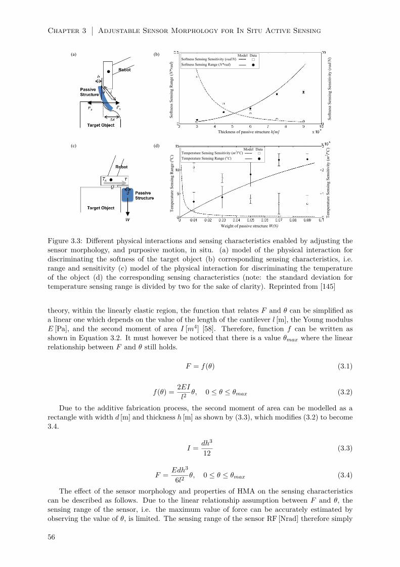
Chapter 3 Adjustable Sensor Morphology for In Situ Active Sensing
Figure 3.3: Different physical interactions and sensing characteristics enabled by adjusting thesensor morphology, and purposive motion, in situ. (a) model of the physical interaction fordiscriminating the softness of the target object (b) corresponding sensing characteristics, i.e.range and sensitivity (c) model of the physical interaction for discriminating the temperatureof the object (d) the corresponding sensing characteristics (note: the standard deviation fortemperature sensing range is divided by two for the sake of clarity). Reprinted from [145]
theory, within the linearly elastic region, the function that relates F and θ can be simplified asa linear one which depends on the value of the length of the cantilever l [m], the Young modulusE [Pa], and the second moment of area I [m4] [58]. Therefore, function f can be written asshown in Equation 3.2. It must however be noticed that there is a value θmax where the linearrelationship between F and θ still holds.
F = f(θ) (3.1)
f(θ) =2EI
l2θ, 0 ≤ θ ≤ θmax (3.2)
Due to the additive fabrication process, the second moment of area can be modelled as arectangle with width d [m] and thickness h [m] as shown by (3.3), which modifies (3.2) to become3.4.
I =dh3
12(3.3)
F =Edh3
6l2θ, 0 ≤ θ ≤ θmax (3.4)
The effect of the sensor morphology and properties of HMA on the sensing characteristicscan be described as follows. Due to the linear relationship assumption between F and θ, thesensing range of the sensor, i.e. the maximum value of force can be accurately estimated byobserving the value of θ, is limited. The sensing range of the sensor RF [Nrad] therefore simply
56
Materials and Method 3.2
equals to Equation 3.4 with θ = θmax. Furthermore, the sensitivity of the sensor SF [rad/N], i.e.the derivative of θ to F , can be easily obtained as shown in Equation 3.6.
RF (d, l, h) =Edh3
6l2θ|θ=θmax
(3.5)
SF (d, l, h) =dθ
dF=
6l2
Edh3(3.6)
It can be seen that increasing the value of d and h will increase the sensing range whiledecreasing the sensitivity, while increasing the value of l will have the opposite effects. Figure3.3(b) shows how these two characteristics change by adjusting the thickness h, with d = 3 mmand l = 4.5 cm, attached to the robot end effector at a 3×3mm2 area. Based on the figure, itcan be seen, for example, that in order to measure the softness of a relatively hard object, alarger value of h may prove to be beneficial as it leads to a larger sensing range to measure asignificant value of force exerted by a hard object.
Owing to the thermoadhesive property of HMA, its mechanical characteristics can also beexploited for sensing temperature. The physical interaction for the case of temperature dis-crimination is shown in Figure 3.3(c). By touching the object with its end effector, due toheat conduction Q, temperature T will increase as To is increased. As a result, the fabricatedmechanical structure will be detached from the robot’s end effector. By collecting experimentaldata, the relationship between temperature T and bonding strength B can be approximated byexponential function as shown by Equation 3.7, where the relationship among bonding strength(B), weight (W ) and the attachment area (A) is explained by Equation 3.8. m is the mass ofthe system, g is gravitational acceleration, and d is the width of the area. The bonding areacan be assumed as a square with width d, while kT1 and kT2 are the constants included in theequations. From experiment, the value of kT1 and kT2 are 7.75× 101 C and 4.70× 10⁻⁵N−1m2
respectively. Based on Equation 3.7, the resolution as well as the maximum and minimum valueof the temperature which can be sensed therefore depends on the weight W [kg] of the builtHMA based structure and the size of the attachment area A [m2] between the structure and therobot end-effector. Due to the designed physical interaction, the built mechanical structure willbe detached once T reaches the value of To.
T = kT1 exp(−kT2B) (3.7)
B =W
A=W
d2=mg
d2(3.8)
The most difficult challenge to realize the physical interaction shown by Figure 3.3(c) is toattach the mechanical structure with an arbitrary value of area A. It will be technically verydifficult, for example, to attach the unit with a very small A. On the other hand, having a verylarge value of A is not feasible due to the time and energy consumption. In this second casestudy, therefore the temperature measurement is limited by the minimum and maximum valueof A. Here, the temperature sensing range is defined by the sensed temperature for the samemechanical structure weight when the attachment area is changed from 3×3mm2 to 4×4mm2
as shown by Equation 3.9. The sensitivity is defined as the derivative of the attachment areaA over the temperature T , shown by Equation 3.10. The sensing range RT [C] and sensitivityST [m2/C] figure for sensing object temperature as a function of the weight is shown in Figure3.3(d). Here, it can be clearly seen that the range of the sensor and sensitivity can be tuned byadjusting weight of the designed mechanical structure. A larger weight, for example, will havea wider sensing range at the cost of the sensitivity.
RT (W ) = T |A=Amax−T |A=Amin
(3.9)
57

Chapter 3 Adjustable Sensor Morphology for In Situ Active Sensing
SF (W ) =dA
dT=A2 exp(
(kT2
(WA
)))
WkT1kT2
∣∣∣∣∣A=Amin
(3.10)
3.3 Results
3.3.1 Verification of the Model
In this section, we will verify the models proposed in the Materials and Method section, anddescribe how different sensor morphology enables the system to sense different physical stimuliwith tunable sensing characteristics.
For the force sensing case study, experimental data were collected by varying the thickness ofthe HMA based cantilever, and measured the corresponding deflection angle and reaction forcefrom the object by using force gauge with resolution 0.05 N. Each experiment was performedfor 10 trials. The RF data collected from the experiments are defined as the maximum valueof force which can still be measured without having the root mean squared error between thereal, obtained, value and the linear model exceeding 0.005. The SF data collected from theexperiments are defined as the gradient of the line that best fits the relationship between themeasured angle and force, for each value of h , i.e. thickness of the structure. The dots inFigure 3.3(b) show the experiment data, plotted in the same figure as the model explained inthe previous section.
For the temperature sensing case study, experimental data were collected by varying the massof a cylindrical shape mechanical structure to 1,3,5,7 and 9 g for attachment area of 3× 3mm2
and 4× 4mm2. The value of RT and RS based on the collected data are shown by the dots onthe right picture of Figure 3.3(d). The number of trials for each experiment was five.
Based on the collected data in each case study, it can be seen that the data adequatelyconform with the proposed model. Therefore, the hypotheses that the proposed system is ableto sense different physical quantities with suitable sensing characteristics by adjusting the sensormorphology can be confirmed.
3.3.2 Demonstration of the Autonomous Capability of The System
After confirming the advantage of the ability to adjust the sensor morphology in situ, in thissection we implement the system to autonomously accomplish case studies of discriminatingvisually indistinguishable objects with respect to softness and temperature autonomously (pleasealso refer to Video S1).
Given the design parameter, Figure 3.4 shows the mechanical structure fabrication for dis-criminating (a) softness, and (b) temperature. As explained in the Materials and Method section,the chosen shape of the mechanical structure for discriminating the object softness is a cantileverwith designed width, length and thickness. As for discriminating the temperature, the chosenshape is a cylindrical shape such that each layer adds the weight of the unit.
The process always starts with additive fabrication, in which the robot manipulator followsa given trajectory while HMA Supplier is controlled to continuously extrude a liquid HMAstring from the nozzle. As shown in Figure 3.4(a1-2), the nozzle moves to the lateral directionsback and forth with a certain given length, which resulting in a stick-like structure when theHMA is solidified at the room temperature. In contrast, the cylindrical structure requires aspiral trajectory of the nozzle to make a layer of disc-like structure, which is then accumulatedvertically as shown in Figure 3.4(b1-2).
Once the additive fabrication is completed, for integrating the fabricated mechanical struc-ture with the rest of the sensing system, the HMA Supplier provide a drop of fluidic HMA that isused for bonding between the HMA Connector and the fabricated structure as shown in Figure3.4(a3-4) and (b3-4). After the cooling period of bonding, the robot is now able to separate the
58

Results 3.3
Figure 3.4: Implementation of autonomous in situ adjustment of sensor morphology. The wholeprocess includes the construction of the unit which is followed by the gripping of that unit bythe HMA connector on the end effector of the robot. (a) Construction and attachment processof the mechanical structure used for discriminating the softness of objects. (b) Constructionand attachment process of HMA mechanical structure for discriminating the temperature ofobjects. In both sequnces, HMA is extruded from the nozzle onto the worspace and a sensor isformed with the motion of the robot end manipulator. Then the formed sensor is attached onthe bottom of the peltier element to pe picked up and probed for sensing softness in (a) andtemeperature in (b). Process can be seen from the attached video. Adapted from [145].
fabricated structure from the fabrication workspace to lift up the structures as shown in Figure3.4(a5) and 3.4(b5).
For the experiments of sensing performance, we constructed six distinctive HMA-based me-chanical structures, i.e. three for softness and the other three for temperature. For softnesssensing, all three structures have the length of l = 4.5 cm while we selected three differentthickness values, i.e. 3, 4.5 and 6 mm. The fabrication processes of these structures can besimply determined by the number of lateral motions repeated. As for the temperature sensing,we tested three different masses of cylindrical structures, i.e. 2.3, 3.6, and 7.7 g, which can bedetermined a number of disc layers accumulated vertically. For all fabricated structures, therobot always makes use of bonding area of 3× 3mm2.
Once the fabrication of mechanical structure is completed, the controller starts the ActiveSensing Process shown in Figure 3.1. The sensing process can be roughly decomposed into twosets of actions, i.e. motor control of the robot manipulator and visual image processing.
The robotic manipulator was programmed to execute a single trajectory for each of thetasks. Assuming that the target object is always located at the same location with respect tothe robot’s coordinate system, the manipulator operates an open-loop position control to placethe position of the end effector. In case of softness sensing the robot manipulator places itsend-effector at the corner of target sensed block and the fabricated stick-like structure is pushedagainst the block. For temperature sensing, the end-effector motion is programmed to place theHMA Connector to touch the edge of sensed object such that the surface of HMA Connectorcould transfer the heat of object to the bonding area where the mechanical structure is attached.
As soon as the motion control has been executed, the visual processing starts, and theprocess involved in the vision algorithm is illustrated in Figure 3.2(d). As explained in theControl Architecture section, all of the visual processing was designed based on the standardvision toolbox in the MATLAB program environment. More specifically, for each the physicalquantity to be sensed, the system starts with capturing a raw gray-scale image, converting it to abinary image, cropping the region of interest, and estimating the deformation of the mechanicalstructure due to the interactions with the target object. For the softness sensing, the systemcalculates the result from ten pictures for every trials, while for the temperature sensing, thevisual system keeps comparing the current and previously captured picture until a predefinedtime. As the output of visual processing, the softness sensing gives angle values of the stick-
59

Chapter 3 Adjustable Sensor Morphology for In Situ Active Sensing
like structure deflected by the reaction force of the sensed object, and the temperature sensingprovides the duration until the cylindrical structure disappears from the visual field.
Figure 3.5: Implementation of autonomous active sensing via suitable motion. Each sequencestarts with the approaching of the HMA mechanical structure onto the object, followed by thecorresponding physical interaction monitored by a visual processing algorithm (a) Image se-quences showing the softness discrimination experiment on a sponge block where the deflectionangle of the HMA string is calculated. (b) Image sequence of the same experiment for an alu-minium block (c) Temperature sensing of the same sponge block which is at a room temperature.(d) Temperature sensing on the aluminium block which is equipped with heaters to adjust thetemperature of the object to a fixed level approximately at 120C. The temperature sensor at-tached to the connection surface between the HMA connector and the aluminium block showsthe gradual increase from room temperature to 59.3. Process can be seen from the attachedvideo. Reprinted from [145].
The proposed approach is tested as a discrimination task on different object pairs for twomodalities; for softness, robot should be able to discriminate a sponge from an aluminium block,for temperature, the sponge is compared with an aluminum block at 120 C. Figure 3.5 showsthe image sequences captured from different sensing tasks. In Figure 3.5(a) and (b), the differentdeflection angle is used to discriminate the stiffer aluminium block from the softer sponge block.In Figure 3.5(c), the robot has to wait for 600 s, the time threshold, because the fabricatedmechanical structure cannot drop at room temperature. In Figure 3.5(d), the robot detects thedrop of the mechanical structure after 210 s.
The experiments were repeated with three different sizes of each mechanical structure forevery physical quantity each of them has 10 trials of experiment. Experimental results are listedin Table 3.1. It can be seen that the discrimination task was always successful for softnessdetection as the deflection angle in sponge was always smaller than in aluminium. As expected,the aluminium exerts a larger value of reaction force, shown by a large value of θ. The largerthe thickness, the large the difference becomes, which is caused by the increasing stiffness ofthe mechanical structure with respect to sponge. It must however be noticed that in order tomeasure the exact value of the force, the resulting value of θ is already outside the sensing rangebased on the derived model. This can be solved by either using a thicker cantilever, or programthe robot to push it for a less distance.
Results for discrimination on temperature detection show that for small weights, the robot
60

Discussion 3.4
Table 3.1: The summary of the experiment result for autonomous discrimination task showingthe relationship between the sensed quantities, the corresponding fabricated passive mechanicalstructure and its dimension, the resulting sensing output, and the discrimination rate. Object1 is always sponge under room temperature. Object 2 is aluminium under room temperatureand heated up aluminium for softness and temperature discrimination respectively. Reprintedfrom [145].
Physical Quantity /Mechanical Structure Mechanical Structure Parameter Sensing Output Discrimination(h = thickness,W = weight) (θ = bending angle, D = time to detach) Rate (%)
Object 1 Object 2Softness / String h = 3 mm θ = 33.71± 3.62 θ = 43.60± 1.56 100
h = 4.5 mm θ = 26.64± 2.78 θ = 43.71± 2.16 100h = 6 mm θ = 22.28± 3.33 θ = 42.13± 2.28 100
Temperature / W = 2.3 g D = 600 s D = 600 s 0Cylinder W = 3.6 g D = 600 s D = 253.7± 137.1 s 90
W = 7.7 g D = 600 s D = 373.1± 182.7 s 70
fails to discriminate two different surface temperatures as the mechanical structures do not dropbefore the waiting time threshold as predicted by the model. When the transducing unit weightis increased, as expected, the discrimination rate increases. However, this did not occur whenthe weight is kept increased. This flaw may be caused by the imprecision of the connection areaduring attachment process. While the assumed surface area is 3 × 3mm2, only 1 mm of faultcan affect the results in an exponential way due to Equation 3.7.
3.4 Discussion
In this chapter, we have suggested a concept and technological approach of active sensing inrobotics system with in situ adjustable sensor morphology. The approach taken is to use arobotic system that is able utilize thermoplasticity and thermoadhesiveness of HMA to repeat-edly fabricate mechanical structure with different shape and size, and easily attach/detach themto robot’s end effector the rest of the system with different configurations, most suitable to thetask. By reviewing the studies of biological systems, we have also argued that the proposedsystem is advantageous for sensing tasks in uncertain environments with possible unanticipatedtask requirements.
The chosen task for the system is to sense different physical quantities, i.e. softness andtemperature, with desirable sensing characteristics. In order to accomplish the task, a suit-able physical interaction model is proposed. It has been shown that by having suitable sensormorphology, along with active sensing capability, the physical quantities can be sensed withdesirable sensing characteristics. To further confirm the efficacy of the system, it is also shownthat the system is able to autonomously accomplish a task of discriminating two visually indis-tinguishable objects with respect to softness and temperature. The emergence of this adaptivefunction is based on the soft sensors which are fabricated through plasticity regulation and thedirectional deformations that occur during object interactions.
As the robot is able to adjust the sensor morphology in situ, the proposed concept mayplay an important role for robots that are aimed to work in ubiquitous terrains, in order tohandle possible unanticipated task requirements in unknown and uncertain environments. Inthis perspective, our approach can be a useful step towards physical adaptation of autonomousrobots. We are also working on embedding a recycling mechanism on the robot which aimsto increase the capacity of glue supply and introduce a new level of autonomy in means ofkeeping track of the fabricated, damaged or detached mechanical structures and putting themback into use for further tasks. Furthermore, as another future work, it is also interesting toexplore additional pre-built sensors that act as the sensor receptor aside from vision, as well asinvestigating more precise models used during the sensing.
It is also worth mentioning that the proposed concept initiates alternative research directions
61

Chapter 3 Adjustable Sensor Morphology for In Situ Active Sensing
as compared to the classical approach of sensing, i.e. having many prebuilt sensors with fixedmorphology. The classical approach, for example, generated a lot of interests in the sensor fusionresearch area. This approach, on the other hand, motivates researches on rapid fabricationrelated technologies, as well as on how to embed cognitive ability to the system in order toincrease the autonomy in deciding when it is necessary to adjust the sensor morphology and/orthe motion, as well as designing the suitable sensor morphology depends on the task requirement.There are, for example, quite a number of works whose long term aim is to enable autonomoustool use in artificial systems (see [194] [195] for recent publications). On the other hand, thework described in this work can also be seen as embedding a robotic system with in situ primitivetool making abilities for a sensing purpose. To explore how the researches can benefit from eachother is also part of our future work.
3.5 Acknowledgements
We thank Dr. Kohei Nakajima for valuable discussions and comments on the manuscript.
62

Chapter 4
Free Space Locomotion throughDragline Forming1
In this chapter, we aim to show that the mobility of wheeled or legged machines can be signif-icantly increased if they are able to move from a solid surface into a three-dimensional space.Although that may be achieved by addition of flying mechanisms, the payload fraction will bethe limiting factor in such hybrid mobile machines for many applications. Inspired by spidersproducing draglines to assist locomotion, the work presented in this chapter proposes an alterna-tive mobile technology where a robot achieves locomotion from a solid surface into a free space.The technology resembles the dragline production pathway in spiders to a technically feasibledegree and enables robots to move with thermoplastic spinning of draglines. As an implemen-tation, a mobile robot has been prototyped with thermoplastic adhesives as source material ofthe draglines. Experimental results show that a dragline diameter range of 1.17-5.27 mm wasachievable by the 185 gmobile robot in descending locomotion from the solid surface of a hang-ing structure with a power consumption of 4.8 W and an average speed of 5.13 cm/min. Withan open-loop controller consisting of sequences of discrete events, the robot has demonstratedrepeatable dragline formation with a relative deviation within -4% and a length close to themeter scale.
The work we present in this chapter is a follow up to the usage of inhomogeneous deformationsfor the physical adaptations of robots as presented in the previous chapters. While we are usingthe same principles and the systematic approach, the function we generate in this chapteris motion instead of sensing. In order to generate motion, we use internal mechanisms toregulate the plasticity of the HMA material similar to Chapter 3 and deform it asymmetricallyto form draglines. In our work, the mobile robot exploits the thermoplastic and thermoadhesiveproperties of the HMA to form draglines inspired from spiders in order to achieve locomotionin free space. The physical adaptation of the robot originates from the fabrication of thisdragline and the ability to change its diameter to carry different payloads by the control on themorphological parameters with thermoplastic regulation.
The generation of the locomotion function is based on the regulation of HMA’s plasticityby the internal mechanisms on the robot. The spider inspired mobile robot we present in thischapter has two main units that contribute to the free space locomotion. The first unit is
1This chapter presents the collaborative work with my colleague L. Wang under the guidance of my supervisorF. Iida. I have designed and built the robotic mechanism which regulates the plasticity of hot melt adhesivematerial with heat control and changes its shape into a dragline through directional deformations with internalmechanisms. I have also helped my colleague L. Wang with the experiments and writing of the journal paperpresented in this chapter along with my supervisor F. Iida. The following journal paper has been adapted andedited in this chapter:
• L. Wang, U. Culha and F. Iida, “A dragline-forming mobile robot inspired by spiders,” Bioinspiration andBiomimetics, vol. 9, no. 1, p. 016006, 2014.
63
Chapter 4 Free Space Locomotion through Dragline Forming
the heated extruder mechanism which is similar to the one presented in Chapter 3. In thismechanism, there is a motor which pushes the cold HMA stick to a heated chamber where theHMA is melted down and extruded from nozzle with a fixed diameter. With this mechanism,the robot can control the volume of the extruded material that will be converted into a dragline.The second unit is a coupled mechanism which contributes to both of dragline formation andlocomotion. This mechanism comprises of two wheels pushed against each other by springsand a motor which drives the shaft of a single wheel. While the heated extruder generates themelted HMA volume, the wheels pull this volume upwards due to the physical connection tothe already formed dragline. With this mechanism, the HMA in the multi-phase state is forcedto deform in an asymmetric fashion to elongate from the nozzle. In this work we assume thatthe robot starts with a formed dragline that is already between the wheels and in is contactwith the newly generated HMA volume. While the wheels pull this newly extruded volume, itgets cold and forms into a dragline, and this process continues as long as there is enough HMAsupplied to the extruder mechanism. During the pull operation, the robot also moves down onthe dragline which generates the motion towards earth. As there is enough friction between theHMA material and the surface of the wheels, the robot can get a strong grip during the wholeoperation. This grip allows this second unit to form draglines and move the robot downwardsat the same time.
In this chapter, the role of the inhomogeneous deformations can be observed during thedragline formation. The extruder and the coupled two-wheel unit are the internal mechanismsin this robot which regulates the plasticity of the HMA and provide the deformations that lead tolocomotion. When the extruder pushes the HMA supply to the heated chamber, the melted HMAis extruded from the nozzle in a certain direction and volume. The most obvious inhomogeneousdeformation is applied by the two wheel mechanism on this newly extruded HMA. As thereis a physical connection between the formed dragline and the extruded material, when the twowheels are rotated by their motor, they pull this melted material upwards creating an asymmetricdeformation. The total time of wheel rotation define the magnitude of the deformation whichis directed upwards. Considering the influence of the gravitational pull, this uni-directionaldeformation on the viscous HMA causes it to deform and elongate into a dragline. In thecurrent setup presented in this chapter, the timing of both extruding and pulling are influencedby the heat dissipation from the environment. In order for the formed dragline to cool downand solidify, the robot waits for a necessary time to extrude more material and pull it upwards.
While the inhomogeneous deformations lead to the free space locomotion, the ability togenerate this autonomously and regulate the plasticity of the HMA material allows the emergenceof a physical adaptation through the formation of the dragline. This adaptation is the generationof draglines with different diameters which allows the robot to carry different loads duringlocomotion. This is closely related with the tensile strength of the HMA material which isexhibited as stronger draglines with thicker diameters. Basically there are two parameters therobot controls to change this diameter: the time of extruding and the time of pulling. While thefirst parameter defines the volume of the extruded material, the second one defines the thicknessand length of the pulled dragline part. With a control over these two parameters, the robotis able to produce draglines with diameters 1.17-5.27 mm which correspond to an estimatedpayload potential of 0.36-10.94 kg. In the case of carrying loads in free space, this autonomousvariation of dragline diameter gives the robot an ability to physically adapt to its task.
The spider inspired robot we present in this chapter embodies two of the major contributionsof this dissertation by demonstrating free space locomotion through forming draglines. Oneof these contributions is the emergence of motion from the differential stiffness. The stiffnessdifference originates from the two phase of the HMA during the fabrication of the dragline. Whilethe already formed dragline between the two-wheel mechanism has higher stiffness, the extrudedHMA has lower viscosity and stiffness. As these two structures in two different phases areconnected to each other, the difference between their stiffness and viscosity leads to the forming
64

Introduction 4.1
of a new dragline piece when the wheels are rotated. By doing so, locomotion behaviour emergesand the robot moves downwards on the formed dragline due to the coupled wheel mechanism.The other contribution can be observed in the fabrication of the dragline and adaptation of itsdiameter through the control in extruding and pulling timings. This operation is the workingdemonstration for the regulation of plasticity for structural adaptation as the dragline’s structureis defined by the regulation of HMA material’s thermoplastic property by the heated extruderand the wheel mechanisms.
4.1 Introduction
Mobile robots are useful machines for transportation, inspection, surveillance, hazard removal,environmental monitoring, extraterrestrial exploration, among other uses. Mobile robots shouldbe able to move in the environment where the tasks are carried out, or even in unanticipatedenvironments. Wheel-based and leg-based technologies have enabled robots to move on groundsurfaces or terrains and to climb on stairs [196], poles [197], slopes, ceilings or vertical surfaces[198]. However, it has not been possible for wheeled or legged robots to move away from solidsurfaces into a three-dimensional space in a controlled way, without the assistance of an existingcable [199–202] or the capability of flying [203]. An existing cable requires the robot to carry awinch, and the total length of the cable is determined by its thickness and the size of the winch.In the case of flying, the payload fraction is an important issue but flying robots currently donot perform very satisfactorily.
In nature, certain terrestrial animals have the ability to move in a free-space in a controlledmanner without flying. One of the representatives is spider, such as Araneus and Nephila. Aspider moves away from a surface in the environment, such as a wall or a branch of a tree, intothe free-space by producing draglines (see Figure 4.1(a)). With this ability, the spider is able toreach another surface, capture a prey, or make a web and position itself on the surfaces of theweb. Such behaviour may inspire design of wheeled or legged robots to extend their mobilityinto a free-space. Furthermore, studies have found that spiders with a larger body mass producethicker draglines [204], and the thickness of draglines from a single spinneret can be varied by thespider [205]. The principle implies that, when implemented in a mobile robot with the dragline-forming capability, the robot may also control the thickness of draglines according to payloadrequirement. This will make the mobile robot capable of covering a large range of payloads.It will also make the robot advantageous over those using an existing cable with a winch in atleast two ways: Firstly, given the same volume of dragline material as the cable in a winchedrobot, adjustable thickness means the robot may maximize the length of the dragline while notsacrificing the payload need; and secondly, the robot has higher chance to adapt to a very largebut unanticipated payload that may exceed the breaking tension of a given cable.
To enable a robot to move from a solid surface into the free space with dragline formation,technical challenges must be tackled since the robot must form a thread while moving withoutany other physical support than the thread itself. Spiders do so with the fourth pair of legsand the dragline spinneret, which includes the major ampullate gland and a related spinningduct. The dragline production pathway in the spinneret has been considerably studied [205,207].The major ampullate gland secretes the spinning protein dope and constitutes the main storagerepository that leads to the duct. The duct is then responsible for fibre formation and terminateswith a valve. After the valve, further processing proceeds in a narrow tubular region and thedragline thread then exits at the spigot. The pathway is mechanically similar to an industrialpultrusion system subject to an initial shear stress. The pulling force comes from the fourthpair of the legs of the spider and/or the gravitational force of the body mass. With such aprocess, spiders weighing a few hundred milligrams are able to produce draglines that are a fewmicrometres thick [204].
From the perspective of robotics, the demand for a combination of dragline formation and
65

Chapter 4 Free Space Locomotion through Dragline Forming
(a) (b)
Figure 4.1: (a) A falling spider (Araneus), reprinted by permission from Macmillan PublishersLtd: [206] © 2006. (b) Front view of a mobile robot with draglines made of source materialthermoplastic adhesives (TPAs). The extrusion mechanism (lower half of the robot) resemblesthe secretion in the major ampullate gland of spiders, and it is labelled in detail. Reprintedfrom [146].
locomotion requires a robotic system to include source material that makes draglines. Further-more, the source material must be able to change its strength so that it can be easily deformedinto a dragline on the one hand and it gives strong physical support for locomotion on the other.In other words, phase transition of the source material is necessary. Spiders do so by liquid crys-tal spinning of draglines [208]. However, liquid crystal spinning requires sophisticated chemicaltechniques which could be implemented in biomaterial engineering [208, 209] but is beyond thefeasibility as an on-board technique within a mobile robot.
The work in this chapter presents a dragline-forming mobile technology inspired by spiders.The technology is based on thermoplastic spinning with an extrusion process that resemblesthe secretion in the major ampullate gland and an open-air deformation process that resemblesthe pultrusion in the duct of the spiders. With thermoplastic spinning, phase transition canbe easily modelled and controlled since strength dependence on temperature is universal formaterial. The technology is realized in a self-contained mobile robot with on-board batteriesand source material of thermoplastic adhesives (TPAs). With a case study of vertical descendingfrom the surface of a hanging structure into a free space, the robot demonstrates locomotionassisted by dragline formation with variable diameters.
TPAs are thermoplastics that have adhesion strength as high as several megapascal at roomtemperature. They have versatile applications and can be used to bond various adherends,from metals, plastics, glass, ceramics, rubbers, stone, to wood [210]. They are easily accessibleand economical as proven in industries such as packaging, furniture, book binding, aerospace,etc. They have also been used in robotics as a general mechanism for automatic mechanicalconnection and disconnection between macroscopic parts [139] and a vertical climbing technologywith a large payload capacity in complex environments [211]. The adhesive property and roboticdemonstrations make it straight forward for a mobile robot to use TPAs to initiate a dragline
66

Materials and Methods 4.2
with attachment to any solid surface. Furthermore, the adhesive property and thermoplasticproperty of TPAs are repeatable [211], which makes them potentially recyclable. The technologypresented in this chapter focuses on thermoplastic dragline formation during locomotion.
4.2 Materials and Methods
4.2.1 A Dragline-Forming Mobile Robot
A robot is designed and prototyped to demonstrate the feasibility of the technology (see Figure4.1(b)). The robot weighs ca. 185 g and has an overall dimension of 5×3×18 cm3 (width,thickness, height). The mechanical structure of the robot mainly consists of two parts i.e.a material extrusion mechanism and a coupled deformation-locomotion mechanism as brieflyintroduced in Section 4.1.
The material extrusion mechanism contains solid TPA (GG02, Dremel, USA) in a cylindricalshape (cross-sectional diameter 7 mm). The mechanism is minimalistic and designed to be easilyintegrated as a part of a robotic system at the centimetre scale like the one presented in Part A,but uses linear actuation and fits smaller TPA sticks. As shown in Figure 4.1(b), the solid TPAstick is linearly delivered through a heating cavity and pushed out of a nozzle. Linear delivery isconverted from a DC gear motor’s rotation through a ball screw fixed with a TPA stick clutch.The clutch is constrained in linear motion by a linear track, the end of which is rigidly connectedwith the DC gear motor (motor 1, 250:1 gear ratio, Pololu, USA) and the heating cavity. Theheating cavity lies in a cylindrical aluminium block and has an opening of 7 mm in diameter atone end and a nozzle with an inner diameter of 4 mm and an outer diameter of 6 mm at theother end. The cavity is heated by six 10-Ω power resistors connected in parallel and insertedin the block around the cavity. The TPA stick is held by the clutch at one end and insertedinto the aluminium cavity at the other end through a silicone tube for leakage prevention. Themaximal travel along the linear track is 10 cm.
The deformation-locomotion mechanism consists of two geometrically identical cylindricalwheels with a diameter of 12 mm, which are contained in a box. As illustrated in Figure 4.2, oneof the wheels is fixed on the output shaft of a second DC gear motor (motor 2, 1000:1 gear ratio,Pololu, USA), and the shaft is fixed on two opposite walls of the containing box. The secondwheel is attached around a second shaft which can move linearly on a track with a fixed lengthon the two walls. The end points of the latter wheel’s shaft are attached to the box with springs,which pull the wheel towards the centre of the mechanism. The track constraints this wheel tomove along a linear route while springs allow it to passively adjust to the variable diameter ofthe formed dragline. The spring force is in a linear relation with the distance between the twowheels, or in other words with the diameter of the formed dragline. The force gives the normalforce which generates the friction between the formed dragline and the wheels (denoted as f ina free body diagram in Figure 4.3), enabling the robot to hold onto the formed dragline whenbeing static (static friction), or move without free fall in the case of descending (kinetic friction).During movement, the mechanism enables the robot to elongate extruded material at the sametime as moving along a formed dragline. Elongation of the material is enabled by tensile stressfrom adhesion forces to the nozzle at one end and to the formed segment of the dragline at theother end. The reaction force of adhesion on the robot is denoted as F in Figure 4.3.
The two parts are arranged in such a way that the deformation-locomotion mechanism is onthe upper body of the robot, and the material extrusion mechanism is on the lower body. Theyare connected by a rigid piece so that the exit of the extrusion nozzle is placed at a distanceof 3 cm under the bottom of the deformation-locomotion mechanism. The distance determinesthe maximal length of the dragline before it gets held by the two wheels, which could be seenas comparable to the distance from the further end of the duct in a spider to its fourth pair oflegs. A fan is attached to the connecting piece so that forced convection for cooling is possiblewhen needed. An electronics unit including two Lithium-Polymer batteries (ICP543759PMT,
67

Chapter 4 Free Space Locomotion through Dragline Forming
Figure 4.2: A coupled locomotion-deformation mechanism based on a two wheeled feeder system.These wheels which rorate in opposite directions can move a cylindrical dragline away fromthe nozzle. Due to the frictional force created by springs which push the wheels towards thedragline, the motion of the two wheeled-mechanism can pull a newly formed dragline from thenozzle (deformation) and move the whole robot along the dragline (locomotion) at the sametime. (a) A schematic showing the side view. Dw is the cross-sectional diameter of the wheels,f is revolutions per unit time for motor 2. (b) A schematic showing the top view. (c) A viewfrom the front-top of the mobile robot during dragline formation. Reprinted from [146].
Renata, Switzerland), two motor drivers (Dual MC33926, Pololu, USA), and a microcontrollerboard (Arduino Pro Mini, Italy) is placed on the two sides of the extrusion mechanism to ensurethe lateral balance of the robot. A summary of the robot is detailed in Table 4.1.
4.2.2 Thermoplastic Spinning of a Dragline
Thermoplastic spinning of draglines can be mathematically represented by three models, i.e.an extrusion model, a deformation model, and a thermodynamics model. The extrusion modelexplains the dependence of material mass flow rate on control parameters such as the shear
68

Materials and Methods 4.2
Figure 4.3: A schematic diagram showing the forces acting on the robot and on the dragline, aswell as the two mechanisms of heat exchange. (Left) Dashed straight arrows indicate conductionand solid curved arrows indicate convection. (Right) Frictional force between the two wheelsof the robot and the dragline is denoted as f, and the adhesion force between the nozzle of therobot and the dragline is denoted as F. Black solid arrows indicate forces on the robot, whilered dashed arrows indicate forces on the dragline. Reprinted from [146].
Table 4.1: Specification of the Mobile Robot. Reprinted from [146].
Mass (g) 185Dimension (width, thickness, height) (cm3) 5×3×18Degrees of freedom 2Extrusion temperature (C) 65-75Power consumption (W) 4.8Battery life with the above power (min) 45Average descending speed with dragline formation (cm/min) 5.13Longest dragline (m) 0.82Range of diameter of dragline (mm) 1.17-5.27
stress exerted by an actuator e.g. motor 1, and design parameters such as the diameter of thenozzle, etc. This dependence has been previously proposed based on Newtonian fluid (furtherdetail may be found in Part A). Once a constant mass flow rate k is determined, the mass Mwithin a duration of extrusion ∆tm1 can be obtained:
M = k∆tm1 (4.1)
The deformation model describes the dependence of dragline thickness on parameters suchas material mass flow, and the speed and duration exerted by an actuator e.g. motor 2, etc.
69

Chapter 4 Free Space Locomotion through Dragline Forming
Deformation here means elongation of the extruded material along the axis of movement, sothat a certain diameter of a dragline may be reached. Elongation of newly extruded material iscaused by the tensile stress when the two wheels pull the structure they hold, e.g. the alreadyformed part of dragline, away from the nozzle. In other words, the tensile stress results adhesionforce on the cross-section of the structure and the cross-section of the exit of the nozzle (thereaction force of which on the nozzle/robot is shown in Figure 4.3 and denoted as F. In themodel, it is assumed that the tensile stress is always sufficient, thus no plastic solid model suchas a Bingham model is considered.
Figure 4.4: A control diagram of descending locomotion with dragline formation based on ther-moplastic spinning. The controller consists of repetitions of a sequence of discrete events in-cluding extrusion of source material (a-b), deformation of extruded material into a certain crosssection which may be coupled with locomotion (b-c), and phase transition through cooling (c-d).More specifically, a certain mass of source material M is extruded and deformed at an initialtemperature T0 into a dragline segment with a cross-sectional diameter of Dfd and a length ofL. The dragline segment is then cooled with thermodynamics T (t). Each event lasts durationof ∆tm1, ∆tm2 and ∆tpt. Reprinted from [146].
Assuming elongation of a given mass of the extruded material M is isochoric and draglinehas a round cross section, as illustrated in Figure 4.4 the geometrical relationship between thelength of the material L after deformation and the diameter of the cross section Dfd is:
Dfd = 2
√M
ρπL(4.2)
where ρ is a constant representing the density of the material. Note that Dfd is upperbounded by the outer diameter of the nozzle (Dno in Figure 4.4) and the diameter of thestructure that the two wheels hold on to (Dsc in Figure 4.4), because the two cross-sectionscarry the stress that is needed for elongation. Since the deformation and locomotion is coupled(Section 4.2.1), the length of the material L after deformation equals the rotational distance ofthe two wheels when slip is negligible. Thus
70

Materials and Methods 4.2
L = πDwf∆tm2 (4.3)
where Dw is the cross-sectional diameter of the wheels, f is revolutions per unit time formotor 2, and ∆tm2 is the duration of the movement of motor 2, as illustrated in Figure 4.2(a).From Equations 4.1-4.3, the dependence of the diameter of the cross section on duration ofextrusion and duration of deformation is clarified.
Table 4.2: Constants for Models. Reprinted from [146].
Density ρ of the TPA(kg/m3) 980Specific heat capacity c of the TPA (J/(kg·C )) 2500Thermal conductivity K of the TPA (W/(m·C)) 0.45Heat transfer coefficient h of open air (W/(m·C)) 9
The thermodynamics model explains the temperature-dependent phase-transition processin an elongated dragline segment, which corresponding to the sub-process of (c)-(d) in Figure4.4. Phase transition of the source material from plastic to solid is realized by cooling. Itsthermodynamics may be modelled with Newton’s cooling law for convection and Fourier’s law forconduction (the two mechanisms of heat exchange is indicated in Figure 4.3). When temperaturegradient is negligible within the material after being elongated, temperature T (t) of the middlepoint of the material may be approximated as:
cMdT (t)
dt= −hAconv(T (t)− Tamb) +
2KAcondL
(T0 − T (t)) (4.4)
where c is a constant representing the specific heat capacity of the material, h is a constantrepresenting the convective heat transfer coefficient, K is a constant representing the thermalconductivity of the material, Tamb and T0 are constants representing the temperature of theambient environment and the nozzle for extrusion, and Aconv is surface area of heat beingconvected and Acond is surface area of heat being conducted. In the case of a cylindrical thread,Aconv corresponds to the outer surface of the cylinder while Acond corresponds to the crosssection:
Aconv = πDfdL
Acond =πDfd
2
4
Assuming deformation occurs immediately after extrusion, the initial temperature of the materialT (t = 0) can be considered the same as T0, and the equation can be solved:
T (t) = C0 − C1 · e−C2t (4.5)
where
C0 =KT0Dfd + 2L2Tambh
2hL2 +KDfd
C1 =2L2h(Tamb − T0)
2hL2 +KDfd
C2 =2(2hL2 +KDfd)
L2cDfdρ
71

Chapter 4 Free Space Locomotion through Dragline Forming
4.2.3 Robotic Locomotion with Dragline Formation
Descending from a solid hanging structure is taken as a case study to show the feasibility ofthe robot locomotion with dragline formation, which mimics spiders falling with a dragline ina controlled way (Figure 4.1(a)). To initiate descending, the robot first holds onto an exist-ing structure that could be grabbed by the two wheels, e.g. a cable or a pole hanging over afree-space. The tip of the structure shall be in contact with the exit of the nozzle in the robot,so that extruded TPA at the initial stage could adhere to the structure. Locomotion is thencontrolled in an open-looped manner with a sequence of discrete events including extrusion,deformation/movement and phase transition. As illustrated in Figure 4.4, in the event of ex-trusion and deformation/movement, motor 1 and motor 2 are turned on for duration of ∆tm1
and ∆tm2 respectively. Extrusion generates material which slightly pushes the formed draglinebetween the wheels and nozzle, but since motor 2 does not move the wheels during extrusion,the dragline in between bends a little bit rather than pushes the robot downwards. The bendingis insignificant and can be quickly straightened during deformation where motor 2 is turn on tomove the wheels. In the event of phase transition which lasts ∆tpt, both motors are turned offand elongated material cools to a certain lower temperature in the open air and form a soliddragline. The open-loop controller is preprogrammed into the microcontroller board.
To assess the performance of the mobile technology, experiments have been conducted tomeasure the phase transition time as well as variability and repeatability of dragline diameter.In all experiments, the ambient temperature was room temperature, and the extrusion tem-perature of the TPA was set at 65-75 C because within the range the material is sufficientlyadhesive/cohesive and plastic. The robot started by holding onto a hanging thread of TPA asthe solid structure in the environment.
For phase transition, the dependence of cooling time on the mass of extruded material isstudied. Three values of mass were extruded and immediately deformed into a given diameterof 4 mm. The temperature change of the formed dragline segment was measured by an externalthermal imager (TIM 160, Micro-Epsilon, Germany) with a sampling rate of 120 Hz. The mea-suring point was set at the middle point of the dragline section, which corresponds to 1.5, 2.5,and 3.5 mm above the nozzle exit for the three cases.
Regarding variability of the dragline diameter, two sets of experiments were carried outwhere the mass of extruded material and the final length of elongation are varied respectively.In the first set of experiment the mass of extruded TPA was varied by turning on motor 1 fora 100% duty cycle for duration ∆tm1 between 0.3 and 2.7 s. Elongation was kept the same byturning on motor 2 for a 100% duty cycle for ∆tm2=0.15 s. In the second set of experiment,∆tm1 was kept with a 100% duty cycle for 1.5 s, while final length of elongation was varied bysetting ∆tm2 with a 100% duty cycle between 0.05 and 0.25 s. Five trials were made for each∆tm1 in the first set of experiment or∆tm2 in the second set. One minute after each trial (∆tpt= 60 s) the formed dragline segment was removed from the robot and the mass and diameterwere measured with a high-precision scale (Voltcraft PS-20) and a digital Vernier scale.
In terms of repeatability, fifteen trials containing a number of repetitions of the completeevent sequence were carried out. ∆tm1 was varied between 0.2 and 2.0 s and ∆tm2 was variedbetween 0.05 and 0.15 s. Repeatability was quantified by relative deviation in cross-sectionaldiameters of segments along single draglines formed within each repetition. Therefore after eachtrial, diameters for each segment along the formed dragline were measured with a digital Vernierscale and compared to the theoretical value.
4.3 Results
Figure 4.5(a) shows the experimental result of the dependence of cooling time on the mass ofextruded material. A TPA mass of 43, 68, and 86 mg was extruded and deformed into a diameterof 3.9-4.1 mm. The dashed lines show theoretical approximation based on the thermodynamics
72

Results 4.3
Figure 4.5: Thermodynamics in thermoplastic spinning of dragline segments. (a) A thermody-namics model showing the dependence of cooling phase transition time of a segment on the massof extruded material in that segment. The model has been experimentally validated with TPAsegments with the same cross sectional area of 4 mm. (b) Snapshots from the thermal imagershowing the nozzle and the segment just above the exit of the nozzle in one of the trials in theexperiment (the lowest curve in (a)). Reprinted from [146].
model, and the parameters used for the model are indicated in Table 4.2 which are within therealistic range obtained from product datasheet and literature [212]. It took approximately180 s for the temperature of the dragline segments to reach a steady state. The steady statewas not room temperature because of continuous energy input from the nozzle. This is furthervisualized by snapshots from the thermo imager in Figure 4.5(b) where the colour of deformedTPA gradually changes to darker. Given the same diameter, the temperature in the steady stateis lower for larger amount of TPA due to the resulting larger surface area of thermal convection.This result indicates that as long as the diameter of the dragline is the same, the more TPAextruded and deformed at a given temperature, the faster it cools. This observation may beexplained by the fact that the more TPA extruded, the more distant the central point of theelongated dragline segment is from the nozzle given the same diameter. The result also helpssetting phase transition duration ∆tpt in the experiment of diameter variability, in which casethe cooling time was set to minute scale. When several repetitions of the process present, ∆tptcould be set to a much smaller value, since further cooling of a formed dragline segment occurswhen it is being moved away from the nozzle towards the wheels. For example, in the experiment
73

Chapter 4 Free Space Locomotion through Dragline Forming
of diameter repeatability, it was possible to set ∆tpt to only 3 s.
Figure 4.6: Variability in diameter of formed draglines. The change of two time parameters:extrusion duration (∆tm1) and deformation duration (∆tm2) can influence the diameter of theproduced dragline segment. (a) Results from varying the extrusion duration. (b) Results fromvarying the deformation duration. Theoretical values from (1) are on the dashed lines. Reprintedfrom [146].
Table 4.3: Experiment Results for Diameter Variability. Reprintedfrom [146].
∆tm1 (s) ∆tm2 (s) Diameter (mm)
First set of experiment
0.3
0.15
1.17±0.320.9 2.24±0.511.5 3.23±0.112.1 3.67±0.282.7 4.24±0.26
Second set of experiment 1.5
0.05 5.27±0.190.10 3.67±0.100.15 3.23±0.110.20 3.12±0.180.25 2.45±0.11
Figure 4.6 shows the results from the two sets of experiments for diameter variability. Theexperiment conditions and results are also summarized in Table 4.3. For the first set of ex-periment as in Figure 4.6(a), theoretical estimation from the deformation model is also plottedwith M estimated from k∆tm1 with an empirical mass flow rate k = 6.75 mg/s, and L calculatedfrom (2) with f = 14 rpm (100% duty cycle for motor 2). It can be seen that the model fitsexperimental data very well. Figure 4.6(b) shows the diameter variation from the second set ofexperiment. In the figure, theoretical estimation is also plotted with a mass of 10 mg (experi-
74

Results 4.3
mental data 10.15±0.65 mg) and L calculated from (2) with f = 14 rpm. It can be seen thatthe model also follows experimental data. Overall, a diameter range of 1.17-5.27 mm has beenachieved for formed dragline segments.
Figure 4.7: Snapshots of thermoplastic dragline formation during descending locomotion underdifferent control parameters. Dragline forming zone is highlighted with yellow squares andthe formed dragline is highlighted with blue shading. (a) ∆tm1 = 0.2 s and ∆tm2 = 0.05 s.(b) ∆tm1 = 1.5 s and ∆tm2 = 0.1 s. The process was initiated at time 0 s with the two wheelsgrabbing a solid structure of a hanging TPA thread. Under the condition in (a) a thinner threadwith a mean cross-sectional diameter of around 2 cm was formed, and under the condition in (b)a thicker thread with a mean cross-sectional diameter of around 4 cm was formed. The formingdragline segments are indicated within dashed yellow rectangular regions. The background rulerwas fixed vertically in the environment and the change in reading indicates movement of therobot along the formed dragline (for example, the reading of 70 or 60 moved upwards, indicatingthe robot was descending). Adapted from [146].
In terms of repeatability, all trials succeeded with more than ten repetitions of event sequenceand the robot managed to move on formed draglines. A maximal value of average descendingspeed of 5.13 cm/min was achieved. While we have tested dragline-assisted locomotion as far as82 cm, there is no limitation in travelling distance unless the source material is used up. Figure4.7 shows snapshots of dragline formation process under two different control conditions. InFigure 4.7(a), a trial (ID 13) with control parameters ∆tm1 = 0.2 s and ∆tm2 = 0.05 s is shown.In Figure 4.7(b), a trial (ID 14) with control parameters ∆tm1 = 1.5 s and ∆tm1 = 0.1 s is shown.The snapshots not only show the process of thermoplastic dragline formation during descendinglocomotion, but also contrast the thickness of draglines under different control conditions. Figure4.8(a) shows draglines formed by the robot while descending in six of the trials (ID 7-12).Figure 4.8(b) shows quantitative data of repeatability from three of the trials, in which thediameters were 3.55±0.08 mm, 2.17±0.06 mm and 2.05±0.06 mm respectively. The theoreticalvalue expected from Equation (2) for each trial is indicated by a dashed line. The result suggestsa maximum of relative negative deviation of -4% between the thinnest segment and the expectedvalue. The deviation came from TPA extrusion and deformation, and physical interactionsbetween the formed dragline segments and the deformation-locomotion mechanism. The relativedeviation shows a good repeatability of dragline formation during locomotion and it is importantfor setting safety margins given a target payload.
75

Chapter 4 Free Space Locomotion through Dragline Forming
Figure 4.8: (a) Draglines formed by the robot during descending from a hanging structure. (b)Repeatability in diameter of formed draglines. Repeatability is quantified as the relative devia-tion between the diameter of dragline segments and a theoretical value. The theoretical valuesexpected from Equation (2) are plotted in dashed lines. Results suggest a relative deviationbetween the thinnest dragline segment and the expected diameter to be within -4%. Reprintedfrom [146].
4.4 Discussion
The range of diameter and relative deviation for repeatability directly determine the payloadcapacity of the mobile technology, when it is assumed that adhesion force between the draglineand a solid surface in the environment is sufficient and the force between the holding mechanismand the dragline is always enough. For a given source material, its ultimate tensile strengthat room temperature is given, then the payload capacity can be estimated. For example, thetype of TPAs used in the study has ultimate tensile strength of around 5 MPa, which gives anestimation of payload potential of 0.36-10.94 kg with the achieved range of diameter. Strongerthermoplastics may be used as source material to further increase the payload range. However,
76

Discussion 4.4
the intrinsic inter-dependence between physical properties of material needs to be clarified, suchas that between viscosity and strength or between softening point and strength, etc., so thatcontrol parameters could be adjusted.
Regarding self-sufficiency of the robot, it is determined by both the energy storage in thebatteries and the material storage of source TPA. The latter determining factor does not presentin conventional mobile robots and worth discussing. TPA is generally reusable in terms of boththermoplasticity and adhesion [211]. However it requires additional mechanisms on-board amobile robot to retrieve a formed dragline and reuse it as source material, which will largelyincrease the complexity of the system. In the current setup the maximal volume of the sourceTPA is determined by the maximal travel along the linear track and the diameter of the solidTPA stick, since the linear delivery for extrusion is only one-way. If an external TPA storagecan be included, the self-sufficiency of the entire robotic system can be significantly improved,in which case only a reset mechanism will be needed to reset the clutch back to its origin oncethe maximal travel has been reached by linear delivery.
From the perspective of control engineering, the present open-looped controller based on a se-quence of discrete events is unlikely to be the optimal for variability and repeatability of draglineformation, neither for the locomotion speed. For example, it is imaginable that the speed canbe increased if extrusion, deformation/locomotion and cooling happen at the same time in acontinuous manner. Since cooling takes more time than extrusion or deformation/locomotion,the speed may be further increased if cooling is made faster. It is also expected that continuousdragline formation and locomotion will avoid unnecessary start and stop of motors, which wasthe cause of relative deviation between repetitions of the event sequence. In order to achieve acontroller for locomotion with continuous dragline formation, the relation between mass flowsfrom extrusion to deformation/locomotion needs to be clarified, and its influence on the ther-modynamics of different dragline segments needs to be understood. That will be the next stepwork for a model-based open-loop controller.
The case study of descending locomotion along a formed dragline provides evidence andquantitative analysis of the proposed approach and may be extended and applied to 3D locomo-tion with formation of multiple draglines and eventually grids. Legged technology is needed toreplace the double-wheel mechanism for that purpose, so that the robot may move away from asingle dragline to a solid surface or a second dragline. Part of the legs should enable the robotto adhere to both a dragline and a surface. A potential simple solution to this is to use gecko-inspired dry adhesives on the legs. Since the adhesive strength of such adhesives is relativelylow (see a quantitative comparison in [211]), the contact area on the legs should be maximizedto provide sufficient adhesion force. One of the possible ways for a robot with legs to form agrid is to start with a single vertical dragline. The robot then climbs back up the dragline andreaches the solid structure and moves on it with legs to where the second vertical dragline istargeted. When a number of vertical draglines have been made in this way, the robot may spanits legs between them and form horizontal draglines with additional degrees of freedom of thenozzle to move horizontally. Thermoplastic formation of horizontal draglines has been provenfeasible without supporting material [213]. When the grid is formed from multiple vertical andhorizontal draglines, 3D positioning is possible and this could partially mimic the web-buildingbehaviour of spiders.
The reported result shows a 185 g mobile robot is able to form draglines with a thicknessof 1.17-5.27 mm. Compared to a spider weighing a couple of hundred milligrams and beingable to produce draglines with thickness of a few micrometres [204], the robot is an up-scaledphysical model of the real spider by three orders of magnitude. When the locomotion of therobot is improved both in speed and continuity such that it resembles the real spider [214,215],the physical model may be used for studying spider behaviours associated with draglines. Forexample, one of the open questions is the cause and measurement of initial stress that movesthe protein molecules in a nematic state from the gland into the duct. That is not trivial to
77

Chapter 4 Free Space Locomotion through Dragline Forming
find out in a living spider, and the controlled physical model may help as long as the polymericflows in the spider and in the robot are comparable and scalable. Another interesting questionis the function of the valve at the end of the duct in dynamics of spider descending and jumping.For example, it has been observed that jumping spiders have a forward pitch movement of theirbody towards the end of a ballistic jump [216]. That is believed to be associated with the valveacting as a brake but no quantitative modelling has been done. A modified robot with additionsof a valve and a jump-launching mechanism may shed light on this.
The robotic platform presented in this chapter shows a working model for physical adaptationusing the directional deformations of soft structures. The adjustable dragline production andthe resulting free space locomotion are examples of adaptive behaviours which emerge from theregulated plasticity and the directionality of deformations applied on a thermoplastic materialby the internal mechanisms of an autonomous mobile robot. During the emergence of thesetwo behaviours, the interaction with the environment plays an important role in the convectionof heat (during the cooling of extruded HMA) and directional gravitational pull (during thedeformation of dragline).
4.5 Acknowledgements
We thank Milan Jovic for improving the design of the robot and Cinzia Peruzzi for collecting thedata for validation of the thermodynamics model. The work was funded by the Swiss NationalScience Foundation Professorship grant no PP00P2123387/1, and the ETH Zurich Researchgrant no ETH-23-10-3.
78

Chapter 5
Finger Motion Range Extension withDifferential Stiffness Joints1
Robotic researchers have been greatly inspired from the human hand in the search of designingand building adaptive robotic hands. Especially, joints have received a lot of attention upon theirrole in maintaining the passive compliance that gives the fingers flexibility and extendable motionranges. Passive compliance, which is the tendency to be employed in motion under the influenceof an external force, is the result of the stiffness and the geometrical constraints of the jointsthat define the direction of the motion. Based on its building elements, human finger joints havemulti-directional passive compliance which means that they can move in multiple axis of motionunder external force. However, due to their complex anatomy, only simplified bio-mechanicaldesigns based on physiological analysis are preferred up to day in robotics. To imitate the humanjoints, these designs either use fixed degree of freedom mechanisms which substantially limit themotion axes of compliance or soft materials that can deform in many directions but hinderfingers’ force exertion capacities. In order to find a solution that lies between these two designapproaches, we are using anatomically correct finger bones, elastic ligaments and antagonistictendons to build anthropomorphic joints with multi-directional passive compliance and strongforce exertion capabilities. We use interactions between an index finger and a thumb to showthat our joints allow the extension of the range of motion of the fingers up to 245% and grippingsize to 63% which can be beneficial for mechanical adaptation in gripping larger objects.
In this chapter we present the design of anthropomorphic robotic fingers with compliantjoints. The joints are comprised of anatomical elements such as bones, ligaments and tendonswhich contribute to the structural compliance with their elastic properties. Differing from manyof the robotic finger designs, the joints in this chapter do not contain any fixed DOF mechanismsuch as hinges or gimbals. The lack of fixed DOF mechanisms allows the joints to move freelyaround the geometry of the bone cavity. However, the free motion is still guided by the ligamen-tous structure which connects the bones together and applies elastic resistance to the motionof the fingers. In our finger joints, ligaments have a multi-layered structure which consists ofseveral elastic elements. The two main elements that define the motion are made of butyl andnitrile rubber which have different stiffness values. The morphology of the ligaments and thedifferential stiffness cause the finger joints to move in a particular way when they are actuatedby the tendons or influenced by the interaction forces.
1This chapter presents my work on the design of compliant anthropomorphic joints under the guidance of mysupervisor F. Iida. I have designed and built the robotic hand that consists of compliant joints, conducted theexperiments and written the journal paper presented in this chapter with the help of my supervisor F. Iida onthe manuscript. The following journal paper has been adapted and edited in this chapter:
• U. Culha and F. Iida, “Enhancement of finger motion range with compliant anthropomorphic joint design,”Bioinspiration and Biomimetics, vol. 11, no. 2, p. 026001, 2016.
79

Chapter 5 Finger Motion Range Extension with Differential Stiffness Joints
There are two ways inhomogeneous deformations are exhibited on the fingers in our chapter.The first way is the design of tendon routing on the finger phalanges. As there are only a lim-ited number of tendons for each finger to generate flexion, extension, abduction and adductionmotions, the way they are routed on the finger becomes an important design decision. Whena tendon is pulled, the tendon transfers the motor torque into force along its longitudinal axisand distributes it to its attachment point on the finger. During this distribution process, thejoints with multi-directional compliance deform and bend in parallel to tendon’s longitudinalaxis; therefore generating a directional deformation. The differential stiffness of the joint struc-ture causes the joints to move in certain directions which is the cause of the inhomogeneousdeformations of joint materials under tendon forces.
Deformation directionality is also observed when the fingers get into interaction with eachother or with the objects in the environment. Unlike the tendon routing which generates aspecific or predefined deformation direction, the forces during physical interaction can arisein many possible magnitudes and directions. Based on the joints’ passive compliance, theseinteraction forces can cause the joints to move in arbitrary directions. In this chapter, weperform several experiments to observe the influence of the interaction forces on the deformationdirection of the joints. We show that the passive compliance of the joints allow an extensionto the actuated range of joint motion if the interaction force direction causes bending that isallowed by the bone geometry and ligaments’ elastic resistance.
The compliant interaction originating from the joint design establishes the physical adap-tation demonstration of this chapter. Normally robotic fingers with fixed DOF joints cannotadapt to the shapes of the objects they are interacting with. Instead, they need knowledge aboutthe environment and the finger at every state of its motion. This dependence on model basedinteraction increases the control complexity of robotic hands. However, the multi-directionalcompliance joints in the fingers of this chapter have the freedom of motion in arbitrary direc-tions guided by the bone geometry and ligament elasticity. This freedom makes the fingers morephysically adaptive as the joint motions are governed by the interaction forces which eventuallydeform the fingers to the shape of the interacted objects. In that case, the necessity to constantlymonitor the interaction or prior information about the environment becomes unnecessary. Byonly the elastic design of the joints, physical adaptation emerges from the motion of fingers dueto interaction forces.
The robotic finger design presented in this chapter utilizes two of the three main contributionsthat lead to adaptive behaviours as we have explained in Chapter 1. The first contribution isthe generation of motion from the differential stiffness of the joints. The stiffness difference ismaintained by the usage of different type of soft elastic materials which regulate the varyingmulti-directional compliance of the fingers under the influence of external forces. This stiffnessdifference originates from the inhomogeneous deformations within the joint ligament structureswhen fingers interact with each other and objects in the environment. The second contributionutilized in this chapter is the regulation of plasticity for structural adaptation. Even though thisregulation is not maintained by internal mechanisms on the robot such as the works presented inChapter 3 and Chapter 4, it has direct influence on the structure on the robotic fingers. In ourwork, we use the thermoplastic and thermoadhesive properties of the HMA material to attachthe ligaments and tendons to the bones. In order to achieve the attachment, we heat up theHMA and form continuous and adhesive surfaces between the joint elements. After the materialcools down, it forms a strong bond between ligaments, tendons and bones which can resist thetensile and shear forces arising due to tendon actuation and interaction with the environment.HMA’s ability to withstand the forces allows the whole finger structure to remain intact andcompliant which leads to physical adaptation during interaction with the environment.
80

Introduction 5.1
5.1 Introduction
Human hand has always been an inspiration for robotic researchers for its manipulation capacity[217] and bond with intelligent life [57]. Being able to adapt to different size and shape ofobjects, squeeze in compact volumes in constrained environments and use tools for a greatrange of purposes are just some impressive functions of the human hand. Therefore, researchershave been working on developing human like robotic hands in order to replicate such functionsfor robotic tasks [218]. However, building a complete replica of the human hand is still verychallenging because of the complexity of tissue anatomies and how they are put together in aconfined space. Also, features such as having more than 25 degrees of freedom (DOF), lightweightdesign, antagonistic tendon and muscle actuation, highly distributed tactile sensing and passivecompliant joints that yield flexibility are additional challenges for robotic hands. That is why,the wide range of robotic hands employ only a part of these features instead of attempting toachieve all of them at the same time [219].
One of the most interesting features of the hand is the complex structure of its joints andits effect on passive compliance. Passive compliance, which is the tendency to be employed inmotion under the influence of an external force originating from the environment, is the resultof the stiffness and the geometry of the joints. These two combined, dictate the constraintson the joints and define fingers’ direction of motion as a result of external forces. Dependingon these, passive compliance of the joints can have either fixed degree of freedom or be multi-directional. Due to its elastic elements such as ligaments and tendons, synovial fluid and thegeometry of the bone cavity [220], human finger joints have multi-directional compliance whichconstitutes the hand’s physical adaptivity property. Conforming to the shapes of unprecedentedobjects, elastically deforming in small volumes and resisting impact stimuli demonstrate humanhand’s adaptation capacity which can be observed during interactions with objects and theenvironment.
Under the guidance of physiological investigation of human hand [220], robotics researchershave developed basically two different approaches in producing anthropomorphic joints as shownin Figure 5.1. First approach employs simplified mechanical representations of the joints withlimited DOF mechanisms such as hinge, gimbals and ball joints. Stanford/JPL [221], Barrett[222], Gifu [223], Robonaut [224], Utah/MIT [225], DLR [226], Shadow [227] and ACT [228]hands are successful examples for robotic hands which use fixed DOF mechanisms to replicatethe joint kinematics of the human hand. While these hands can make use of inverse kinematicsto provide precise position control and produce strong forces at finger tips due to rigid limbstructure, their passive compliance is either non-existent or highly constrained to a fixed axis ofmotion because of their joint mechanisms. Therefore, in order to demonstrate adaptivity duringinteraction, these hand designs rely on either active impedance control to constantly monitorthe force they exert, or position control to move their fingers to postures where passive elementscan be effective in allowed, constrained directions. Achieving compliance in these ways does notonly require more complicated controller regimes but also prior knowledge about the workspaceand the target objects.
Robotic hands that belong to the second approach, such as Hirose [229], Pisa/IIT [87],FRH4 [91], SDM [84], iHY [85], Cianchetti [86] and RBO hand 2 [92] use soft deformablematerials instead of fixed DOF mechanisms at their joint locations. These robots are generallyunderactuated due to having larger DOF than their actuators; however they show importantprogress in demonstrating passive compliance during interaction by relying on the mechanicaladaptation capacity of their joint and finger designs. Unlike in the joint designs in the firstapproach, less constrained joints that generate larger DOF allow multi-directional complianceand let these designs to exploit environmental niche and interaction physics to adaptively graband manipulate objects [93,94]. Additionally, such hand designs reduce the computational loadon feedback controllers, and make use of soft interaction physics with the environment [230].However, these hands mainly face two problems: (1) the softness of their joints or limbs hinder
81

Chapter 5 Finger Motion Range Extension with Differential Stiffness Joints
Figure 5.1: The choice of anthropomorphic robot hand lying in between two extreme ends ofrobotic hand designs. To one end, rigid limbs that attached to each other with hinge type jointsmanifest precise control and the ability to exert large amounts of force but inflexible structureand fragile interaction. To the other end, completely soft limbs and virtually infinite degreesof freedom allow enhanced conformity and softness during interaction but reduced actuationcontrol capacity. Reprinted from [147].
their force exertion capacities, and (2) having a larger DOF than the limited number of actuatorsincrease the gap between actuation and posture space.
When these two groups of approaches are compared, it can be seen that passive complianceand how it is maintained, mainly describe the behaviour of the hands. At one end, the directionof the compliance is defined by and constrained into fixed axis of motion with special jointdesigns such as hinges and gimbals. And at the other end, these constraints are effectivelyloosened by joints with soft and deformable materials that allow multi-directional compliance.From the perspective of anthropomorphic hand and robotics research, finding a solution inbetween these two end points is a motivating objective. Such an approach will be addressingthe challenges in how to regulate the directions of joint compliance by structural design and useof different materials, yet still maintaining a sufficient amount of force exertion and establishinga closer actuator-finger posture relation. Hands that are designed this way will be bringing theadvantages of both ends together, making them more adaptive, less dependent on active control,stronger in grasping forces and less fragile during interactions with environment.
In those terms, human hand joint design presents a valuable example; however researchershave not yet integrated the actual source materials, i.e. anthropomorphic elements of the joints.Bones, elastic ligaments, synovial fluid and muscles/tendons together contribute to the passivecompliance of the human hand joints, but researchers preferred to mimic the behaviour of a partof them so far. To best of our knowledge, the joint design closest to a complete integration isthe variation of the ACT Hand’s joint which replaces the hinge and gimbals type mechanismswith anatomically correct bones and ligaments [83]. Although these artificial joints have closefit with their human counterpart’s features, the elastic capacity of the joints during object orfinger interaction are not demonstrated.
In this chapter we are presenting our compliant anthropomorphic joint design to achievemulti-directional compliance by applying a bio-inspired solution in between two ends of handjoint design approaches. Differing from other robotic hands, we use anthropomorphic designelements like bones, multiple elastic ligaments and tendons in order to build our joints and
82

Methods 5.2
regulate their DOF and passive compliance. We build a robotic hand with an index fingerand a thumb which are actuated with fourteen antagonistic tendons. Our experiments aim toenhance the range of motion of our fingers with interactions between the index finger and thethumb, and extend the gripping size with a resizeable object larger than the natural grip size.We show that our anthropomorphic design can tackle various shortcomings of other groups ofrobotic hands. The bone cavity geometry, tendon routings and the multi-layer elastic ligamentencapsulation can provide multi-directional passive compliance during physical interactions andenable the extension of finger motion ranges. Also the rigid bone structure along with hightensile strength tendons allow the transfer of actuator torque to finger tips for more effectiveforce exertion. Lastly, overall design contributes to an establishment of actuator to finger posturerelation which is an important premise for underactuated robot control.
In this perspective, our platform aims to have a better understanding of human hand byexperimenting on joints’ role in the finger functions, the relationship between multiple tendonsand finger positions, and the role of passive compliance during object interactions. Additionally,it suggests a template for future directions to explore learning motor control of underactuatedfingers, investigate distributed tactile sensing and impact recovery. In conclusion, we believethat our research can contribute to the development of improved prosthetics and broadening ofhuman-robot interaction with more recognizable robot hands that can perform better and saferaround humans.
The structure of this chapter is as follows. In Section 5.2 we aim to provide informationabout our methods for defining the anthropomorphic model, the materials we use, how to buildthe fingers, the actuation mechanisms and the visual feedback platform we use for experiments.We show the natural range of motion of the fingers and how this range is extended with activefinger interactions via experiments in Section 5.3. We discuss the features of our fingers, andhow they can be improved in future works and conclude our work in Section 5.4.
5.2 Methods
5.2.1 Anthropomorphic Model
Human hand is a complicated organ consisting of 27 bones, about 40 muscles and more than25 DOF [217, 220]. In the work we present in this chapter, we only focus on the details of thethumb and the index finger, which have important roles in the overall hand functions [231–233].Both fingers have a metacarpal, proximal and distal phalanges, where index finger has an addi-tional middle in between metacarpal and the proximal. The joints between these phalanges arecalled Distal Interphalangeal (DIP), Proximal Interphalangeal (PIP) and Metacarpo-phalangeal(MCP) for the index finger and Interphalangeal (IP), Metacarpo-phalangeal (MP) and Car-pometacarpal (CMC) for the thumb. We are using the abbreviation “MP” for the thumbmetacarpo-phalangeal joint to distinguish it from the index joint with the same name. TheDIP, PIP of the index and IP and MP joints of the thumb has 1 DOF, where MCP of the indexhas 2 and CMC of the thumb has 3 DOF. There are a number of pulley locations, namely A1-A5 in index and A1-A2 on thumb, for the routing of tendons over the phalanges. The complexligament shell around the joint gaps holds the synovial fluid, which generate low friction on thebone surface, while providing structural elasticity.
By looking at the anatomy of the right hand, we define our anthropomorphic fingers to alevel of bio-mimicry. Figure 5.2 (a) shows the dorsal view of the simplified tendon arrangementwe define in our robotic hand. There are three sets of antagonistic tendon pairs for the indexfinger and four for the thumb. These tendons go through pulleys, whose locations are inspiredfrom their anatomic counterparts to provide basic finger motions such as flexion/extension andabduction/adduction. While all the pulleys and tendons remain on the index finger, the adductortendon of the thumb’s metacarpal goes through the metacarpal of the middle finger in order
83
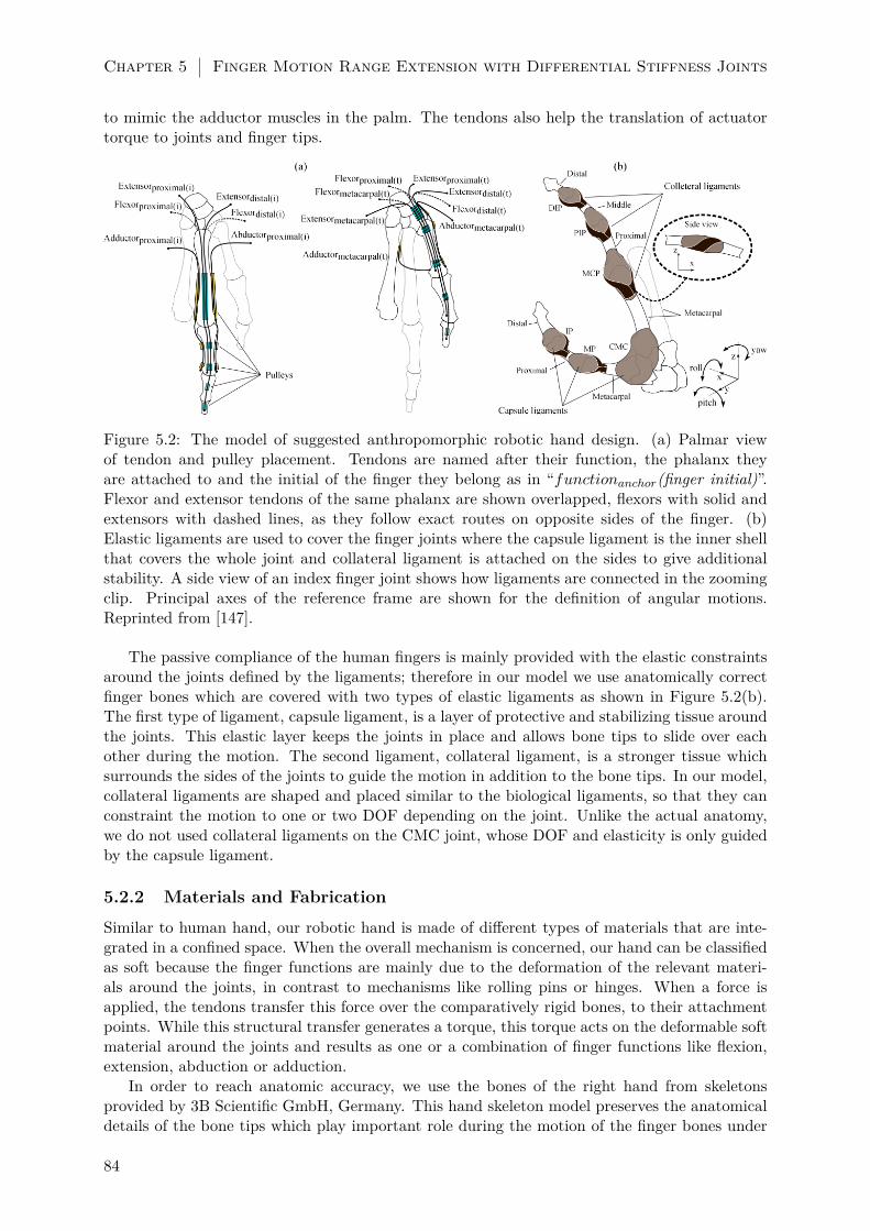
Chapter 5 Finger Motion Range Extension with Differential Stiffness Joints
to mimic the adductor muscles in the palm. The tendons also help the translation of actuatortorque to joints and finger tips.
Figure 5.2: The model of suggested anthropomorphic robotic hand design. (a) Palmar viewof tendon and pulley placement. Tendons are named after their function, the phalanx theyare attached to and the initial of the finger they belong as in “functionanchor(finger initial)”.Flexor and extensor tendons of the same phalanx are shown overlapped, flexors with solid andextensors with dashed lines, as they follow exact routes on opposite sides of the finger. (b)Elastic ligaments are used to cover the finger joints where the capsule ligament is the inner shellthat covers the whole joint and collateral ligament is attached on the sides to give additionalstability. A side view of an index finger joint shows how ligaments are connected in the zoomingclip. Principal axes of the reference frame are shown for the definition of angular motions.Reprinted from [147].
The passive compliance of the human fingers is mainly provided with the elastic constraintsaround the joints defined by the ligaments; therefore in our model we use anatomically correctfinger bones which are covered with two types of elastic ligaments as shown in Figure 5.2(b).The first type of ligament, capsule ligament, is a layer of protective and stabilizing tissue aroundthe joints. This elastic layer keeps the joints in place and allows bone tips to slide over eachother during the motion. The second ligament, collateral ligament, is a stronger tissue whichsurrounds the sides of the joints to guide the motion in addition to the bone tips. In our model,collateral ligaments are shaped and placed similar to the biological ligaments, so that they canconstraint the motion to one or two DOF depending on the joint. Unlike the actual anatomy,we do not used collateral ligaments on the CMC joint, whose DOF and elasticity is only guidedby the capsule ligament.
5.2.2 Materials and Fabrication
Similar to human hand, our robotic hand is made of different types of materials that are inte-grated in a confined space. When the overall mechanism is concerned, our hand can be classifiedas soft because the finger functions are mainly due to the deformation of the relevant materi-als around the joints, in contrast to mechanisms like rolling pins or hinges. When a force isapplied, the tendons transfer this force over the comparatively rigid bones, to their attachmentpoints. While this structural transfer generates a torque, this torque acts on the deformable softmaterial around the joints and results as one or a combination of finger functions like flexion,extension, abduction or adduction.
In order to reach anatomic accuracy, we use the bones of the right hand from skeletonsprovided by 3B Scientific GmbH, Germany. This hand skeleton model preserves the anatomicaldetails of the bone tips which play important role during the motion of the finger bones under
84

Methods 5.2
applied torque. The bones are made of PVC plastic with an approximate 67 MPa tensile strength;therefore they behave as rigid bodies within the force range generated by our system. In ourresearch we only use the bones of the index finger, the thumb, the metacarpal phalanx of themiddle finger and trapezoidal bones of the wrist for structural completeness; however only theindex finger and the thumb are actuated. The physical parameters of the actuated bones aregiven in Table 5.1.
Table 5.1: The physical parameters of the index finger and thumb. Reprinted from [147].
Finger Phalange Name Length(mm)Index Distal 16
Middle 24Proximal 38Metacarpal 70
Thumb Distal 24Proximal 31Metacarpal 48
Human finger joint structure is a multi-layered mechanism composed of several collagen andelastic fibre based tissues covering the bones and the joint cavity. Anatomical research showsthe main contributor to joint stability and motion are tendon and muscle forces; however theligament structures are the first level tissues that play important role in passive stability andelasticity [141]. In our research, we focus on the two ligament tissue layers: the joint capsuleand collateral ligaments. As the first layer of tissue that spherically covers the joint cavity, jointcapsule binds the bones together, encapsulates the joint cavity to store the synovial fluid andprovides passive elasticity to the joints [141]. Compared to the joint capsule, collateral ligamentshave a denser collagen structure that makes them more stable while they connect the bones toeach other as sheets of ligaments of several layers [234]. Both of these elements are crucial inthe general adaptivity and the stability of the human fingers.
Inspiring from the anatomical structure of the human joint we are using two different typesof elastic materials for the ligaments which are the main sources of deformation in the robotichand. The first one is the capsule ligament which completely covers the joint space in betweenthe bones. We are using black nitrile rubber (NBR sheet, White Cross Rubber Products, UK),which is widely used for manufacturing medical examination gloves, that has approximately5 MPa of tensile strength. This material is strong enough to keep the bones attached to eachother and preserve the gap between the bone tips at minimum. It can also elongate under appliedtorque to generate the bending motion of joints. The second one is the collateral ligament whichwinds around the bone gap for torsional stability on the phalanges. We use black butyl rubber,(Butyl IIR sheet, White Cross Rubber Products, UK) that has an approximate 7 MPa tensilestrength which makes it more resistive to strain compared to the capsule ligament, but elasticenough for joint compliance. These two types of materials are chosen to mimic the multi materialligament composition and their co-related elasticity influence in the real human hand ligaments,but not to replicate their actual quantitative elasticity properties.
The tendons which carry the output force to the bones are made of 0.55 mm diameterDyneema®PE braided fishing lines with 3.1 GPa tensile strength. Considering the force out-put of the actuation system, these tendons do not elongate under stress, therefore making theexperiments repeatable. The pulleys which the tendons go through are made of Polytetrafluo-roethylene (PFTE tubes, Farnell, UK) with Teflon coating which generates a low friction innersurface. In order to assemble and glue the required materials to each other, we use a thermo-plastic elastomer variant hot melt adhesive (HMA, Pattex, Henkel, UK). When heated up, thismaterial turns into viscous liquid form and fills the gap between two complex surfaces to makea bond when cooled down. Previous studies in our laboratory shows that this material can
85

Chapter 5 Finger Motion Range Extension with Differential Stiffness Joints
create strong bonds between multiple materials, and can resist to tensile and shear stress evenon small surfaces [139]. Under the guidance of these studies, we choose to use this material tocreate continuous and strong bonding surfaces between the PVC based bones and rubber basedligaments in our joints.
Figure 5.3: Fabrication stages of the index finger. Capsule ligament is covering the joint cavityby attaching to end parts of bones with hot melt adhesives (a-c). Collateral ligaments whosegeometry is highlighted in (e) are placed on the side for torsional stability of joints (d-e). Re-maining joints are covered with ligaments with the same method (f). Low friction short tubepieces are placed on anatomically inspired pulley positions (g). Pulleys are fixed with addi-tional hot melt adhesives and nitrile rubber to withstand torques (h). Tendon cables are routedthrough pulleys and longer tubes on non-moving bones (i). Reprinted from [147].
Due to the complexity of the anatomically correct pieces and continuum surfaces we assembleour fingers by hand as shown in Figure 5.3. First we cut 30×30 mm sheets of nitrile rubber with0.1 mm thickness to surround the bone cavity. These pieces are glued to the tips of the bones byleaving a small gap (∼0.2 mm) between to allow the bones to slide over each other while movingunder torque. We glue the collateral ligaments on top by cutting 10×30 mm sheets with 0.7 mmthickness. Inspired from the natural example, these ligaments make a twist around the joint byattaching the top of the base bone to the bottom of the follower bone. We repeat the ligamentattachment process for every joint, excluding the CMC from collateral ligaments.
When the ligaments are complete, we start gluing the pulleys by cutting small pieces fromthe low friction PFTE tube on the fingers. Each pulley is a tube with 1 mm diameter and 10 mmlength which is placed similar to the locations of A1 to A5 pulleys on the index finger and A1-A2pulleys on the thumb. We mimic the adductor muscle of the thumb by placing a pulley on themetacarpal of the middle finger. Longer tubes are placed on the metacarpal phalanx of the indexand middle finger and the glued wrist bones to route the tendons from the joints to the actuationmechanism. In order to increase the strength of the pulleys against the torque generated duringbending motions, we use additional glue and nitrile rubber to make fixation rings around thepulleys. We place the 0.55 mm diameter tendons at the last stage of the assembly by pullingthem through the tubes and pulleys. We fix the anchor point of the tendons on the bones byknotting and gluing, while the other end is kept free to be attached to the actuation mechanism.
The overall assembly takes approximately 3 hours with the index finger, thumb, the metacarpalof the middle finger and the wrist bones. The resulting robot hand, which weighs 70 grams, has
86

Methods 5.2
14 tendons and two actuated fingers, can be seen in Figure 5.4(b).
5.2.3 Actuation Mechanism
The actuation mechanism of our robot hand consists of 14 tendon driving modules which can becontrolled independently from each other. Each module has a microcontroller, a motor driver, a100:1 gear ratio Pololu®6V DC motor with 0.22 Nm stalling torque output, and a motor encoderfor position feedback inside a 30 × 40 × 50 mm box. There is a pulley with a circumference of22 mm attached to the motor shaft, which is connected to the free end of a tendon. Thesemodules are connected to each other over a master communication unit with a I2C bus. Eachmodule runs a PD controller loop whose target position can be set by computer and transferredto the master communication unit with a USB connection. Complete platform is shown inFigure 5.4.
Due to the position encoder, circumference of the motor pulley and tendons with high tensilestrength, we can control the rotation of the motors up to 0.3 and stroke of the tendons up to0.02 mm precision. The precise control of the motors also allows us to detect stalls without anyadditional sensor unit. When a single tendon driver module is commanded to pull a tendon to acertain target value, the position and the rotational velocity of the motor shaft can be monitoredto check if the motor is stalling. By using the PD controller in each module, we can detect astall when the error between the current and the target tendon stroke is larger than a toleranceamount, 0.5 mm in our case, and the motor velocity is zero.
Figure 5.4: Complete platform which hosts the assembled fingers and the actuation mechanism(a). The index finger, thumb and the middle finger metacarpal are connected to wrist bonesand fixed on top of the platform (b). There is one actuation module for every tendon which iscontrolled with a micro controller (c). Reprinted from [147].
5.2.4 Motion Capturing
The complexity of the hand structure and the soft joints in particular make it impossible forour platform to derive inverse kinematics and relate tendon to finger positions. As we do not
87

Chapter 5 Finger Motion Range Extension with Differential Stiffness Joints
implement an on board soft sensor in this research, we are gathering the 3D position informationof the fingers from a motion capturing setup.
As shown in Figure 5.5, our motion capture arena has four high definition web cameras whichfocus on the hand platform in the center. These cameras are placed so that at least two of themsee all of the markers at a single time instance. We place red markers on each actuated phalanxof the index finger and yellow for each actuated phalanx of the thumb. There is also a whitemarker on the surface of the platform to fix the reference frame. The arena is covered in blackto generate a high contract scene for the images that we capture from the cameras.
Figure 5.5: Motion capture setup which tracks colour markers on the fingers with four differentcameras. Each phalanx has a colour marker attached to it, making six markers in total. There isa white marker on the surface of the platform to set the reference frame. Reprinted from [147].
We use MATLAB ®and its computer vision system toolbox [235] to perform the 3D recon-struction of our fingers from camera images. First, we use the camera calibration applicationfrom the vision system toolbox to calibrate the cameras and produce the camera matrices thatgive information about the intrinsic, extrinsic and the lens distortion parameters. This is doneby placing a checker-board pattern picture, whose size, length and amount of squares are knownand registered to the toolbox, in various poses within the range of all four cameras. Each poseof the checker-board is captured as images and the corner points on the checker-board patternare detected in each camera image. As the real size of the checker-board is known, the detectedcorner points and their geometry in the images allow the calculation of the 3D space pose ofthe checker-board and the relative position of all the cameras to each other. In order to followthe hand postures, we use a simple RGB colour filter algorithm to detect the markers on thecaptured images. These detected marker positions and camera matrices are related to each toreconstruct a 3D scene from captured 2D images using a customised version of Direct LinearTransformation (DLT) algorithm [236]. Only the images which detect seven colour markers areconsidered as the source for triangulation in our algorithm.
88

Results 5.3
5.3 Results
5.3.1 Tendon Stroke Limits
Before every experiment, tendon calibration is necessary to ensure a repeatable and reliableplatform. As we control the position of the fingers with tendon strokes, it is substantial to makesure that tendons are always in their correct position. In order to do so, we release all thetendons to begin the calibration process. Following that, we pull every antagonistic tendon pairwith a stroke step of 0.1 mm simultaneously until a motion on the relevant finger is detected bythe motion capture system. The last value of the tendon stroke which did not generate a motionis registered as the resting position of that particular tendon and stored as a reference value.This ensures a minimum necessary pre-tension on the tendons and consequently calibrates theplatform.
After calibration, we start our experiments with detecting the stroke limit of each tendonuntil the load from its attached joint causes a stall at the actuating motor. In this experiment,each tendon is pulled with a stroke step of 0.2 mm until the motor stall is detected as explainedin Section 5.2.3. While a tendon is being pulled, all other tendons are kept at resting positionto incorporate the resisting effect of antagonistic tendon pairs and elastic ligaments. Therefore,given the current setup, tendon stroke limits also represent how much tendons can be pulledwith our actuators. Figure 5.6 shows the maximum strokes for each tendon until they reachtheir load limit of the motors.
Figure 5.6: Maximum stroke of tendons at their load limits. The six tendons in the light shadedregion belong to index finger, and the other eight tendons in the darker region belong to thethumb. (We use abbreviated versions of tendon naming; flexor: fl, extensor: ex, abductor: ab,adductor: ad, distal: d, proximal: p, metacarpal: me). Reprinted from [147].
We see that the maximum strokes, or load limits, generally have similar values for antagonis-tic tendon pairs of the same phalanx as flexor-extensors and abductor-adductors. However thereare several exceptions like the flexor-extensor of the index proximal and abductor-adductor ofthe thumb metacarpal. The main reason for the difference in the formal case as the flexor flp(i)can be pulled more than the extensor exp(i) is the geometry of the bone tips and the mechanicalconstraint it enforces on the joint motion. We can explain the difference between the adductorand abductor of the thumb metacarpal, i.e. abme(t) and adme(t), by the effect of a larger spacefor motion given by the tendon routing over the middle finger metacarpal.
5.3.2 Range of Motion
First of all we find the joint motion limits by manually exciting the phalanges. During thisexperiment, tendons are not active to show the physical limits of the joint mechanisms which
89

Chapter 5 Finger Motion Range Extension with Differential Stiffness Joints
are defined by the ligaments and the bone anatomy. Those limits, as seen in Table 5.2, showsimilarity to the actual limits of human hand reported in literature [220,237,238].
Table 5.2: Finger joint motion limits. Reprinted from [147].
Finger Joint Minimum Maximum Human HandIndex DIP 60 extension 80 flexion 50.4 ± 6.6 (flexion/extension)
PIP 25 extension 110 flexion 89.5 ± 11.7 (flexion/extension)MCP 30 extension 70 flexion 85.3 ± 18.4 (flexion/extension)
35 abduction 35 adduction 50.4 ± 6.6 (abduction/adduction)Thumb IP 60 extension 90 flexion 80 (flexion/extension)
MP 40 extension 80 flexion 70 (flexion/extension)CMC 35 extension 40 flexion 45 (flexion/extension)
35 abduction 40 adduction 40 (abduction/adduction)Range of motion of human fingers are adopted from [237] for index finger and [238] for thumb
After acquiring the tendon limits, we explore the active range of motion of the joints bydoing an exhaustive search on the tendon stroke combinations. For this, we define Sj(i) forindex finger and Sj(t)) for thumb, which show the stroke state of a tendon j; in either of pulledto limit or relaxed. “Pulled to the limit state” means that the tendons are pulled to the limitstroke values which are shown in Figure 5.6. “Relaxed state” means that the tendon is releasedto the negative motor direction with half the magnitude of its load limit. This ensures that thesearch also looks for the combination where antagonistic tendon pairs can function effectivelywithout generating resistive pulls in counter acting motions. Considering the two phases, wesearch 26 combinations for the index finger and 28 for the thumb. In order to avoid the effect ofphysical interactions between two fingers, we run the tests for each finger separately.
By using customised DLT algorithm repeatedly, we detect the location of markers on thefinger phalanges and generate a 3D reconstruction of the hand for the pose it takes as a resultof each action within the tendon combination set. We take a single, constant base point of thehand as the middle point between the trapezoid and trapezium bones in the wrist, which iscalculated with respect to the reference frame, fixed on the white marker. For every 3D pointspace resulting from a tendon action, we calculate the angle between the each phalanx and thisbase point on three basic axes, i.e. yaw, pitch and roll for all of the experiments. Then we collectthese angles to represent the range of motion of the fingers given the limits of the tendons, whichcan be seen in Figure 5.7.
The range of motion shown in Figure 5.7 are the results of all the tendon actions actingon the fingers separately, meaning that there are no interactions between the fingers or withthe environment. The choice of representing the range of motion in three principal axes withrespect to a single base point has several advantages from the perspective of our work. First,it can show the possible overlapping workspace of the index finger and the thumb, which is animportant indication to possible interactions between fingers that can influence motion range.Second, one dimensional lines in these three principal axes can more clearly represent the scalarvalues of range of motion of bodies in 3D space and how they will be extended with fingerinteractions, which will be shown in the following sections. Third, it demonstrates the results ofmulti-directional compliance of the joints, which can be seen as motions in 3D space. And lastly,as our system is underactuated and the influence of tendons on phalanx motions are correlated,this representation is useful to establish the tendon action-phalanx angle relation which will bediscussed in the next section. Table 5.3 shows the quantification of the range of motion of eachphalanx at the end of the experiments.
The gist of Table 5.3 shows that each phalanx exhibits motion in all of three axes. In additionto the multi-directional joint compliance, this is a direct result of exhaustive search on tendonaction combinations where tendons working on perpendicular axes; e.g. flexor and abductor,
90
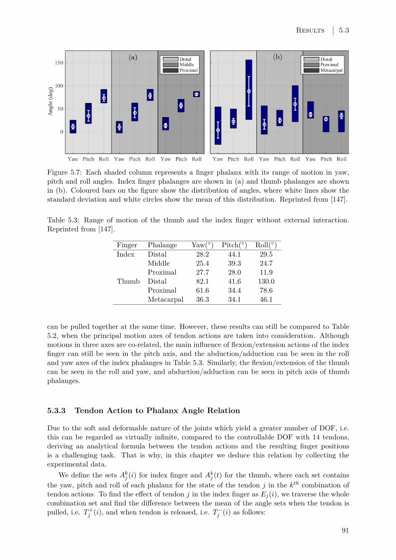
Results 5.3
Figure 5.7: Each shaded column represents a finger phalanx with its range of motion in yaw,pitch and roll angles. Index finger phalanges are shown in (a) and thumb phalanges are shownin (b). Coloured bars on the figure show the distribution of angles, where white lines show thestandard deviation and white circles show the mean of this distribution. Reprinted from [147].
Table 5.3: Range of motion of the thumb and the index finger without external interaction.Reprinted from [147].
Finger Phalange Yaw() Pitch() Roll()Index Distal 28.2 44.1 29.5
Middle 25.4 39.3 24.7Proximal 27.7 28.0 11.9
Thumb Distal 82.1 41.6 130.0Proximal 61.6 34.4 78.6Metacarpal 36.3 34.1 46.1
can be pulled together at the same time. However, these results can still be compared to Table5.2, when the principal motion axes of tendon actions are taken into consideration. Althoughmotions in three axes are co-related, the main influence of flexion/extension actions of the indexfinger can still be seen in the pitch axis, and the abduction/adduction can be seen in the rolland yaw axes of the index phalanges in Table 5.3. Similarly, the flexion/extension of the thumbcan be seen in the roll and yaw, and abduction/adduction can be seen in pitch axis of thumbphalanges.
5.3.3 Tendon Action to Phalanx Angle Relation
Due to the soft and deformable nature of the joints which yield a greater number of DOF, i.e.this can be regarded as virtually infinite, compared to the controllable DOF with 14 tendons,deriving an analytical formula between the tendon actions and the resulting finger positionsis a challenging task. That is why, in this chapter we deduce this relation by collecting theexperimental data.
We define the sets Akj (i) for index finger and Akj (t) for the thumb, where each set containsthe yaw, pitch and roll of each phalanx for the state of the tendon j in the kth combination oftendon actions. To find the effect of tendon j in the index finger as Ej(i), we traverse the wholecombination set and find the difference between the mean of the angle sets when the tendon ispulled, i.e. T+
j (i), and when tendon is released, i.e. T−j (i) as follows:
91
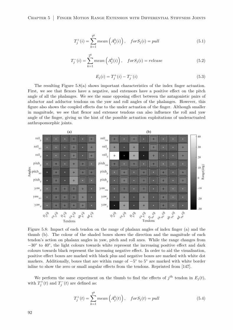
Chapter 5 Finger Motion Range Extension with Differential Stiffness Joints
T+j (i) =
26∑k=1
mean(Akj (i)
), forSj(i) = pull (5.1)
T−j (i) =
26∑k=1
mean(Akj (i)
), forSj(i) = release (5.2)
Ej(i) = T+j (i)− T−j (i) (5.3)
The resulting Figure 5.8(a) shows important characteristics of the index finger actuation.First, we see that flexors have a negative, and extensors have a positive effect on the pitchangle of all the phalanges. We see the same opposing effect between the antagonistic pairs ofabductor and adductor tendons on the yaw and roll angles of the phalanges. However, thisfigure also shows the coupled effects due to the under actuation of the finger. Although smallerin magnitude, we see that flexor and extensor tendons can also influence the roll and yawangle of the finger, giving us the hint of the possible actuation exploitations of underactuatedanthropomorphic joints.
(a) (b)
Figure 5.8: Impact of each tendon on the range of phalanx angles of index finger (a) and thethumb (b). The colour of the shaded boxes shows the direction and the magnitude of eachtendon’s action on phalanx angles in yaw, pitch and roll axes. While the range changes from−30 to 40, the light colours towards white represent the increasing positive effect and darkcolours towards black represent the increasing negative effect. In order to aid the visualisation,positive effect boxes are marked with black plus and negative boxes are marked with white dotmarkers. Additionally, boxes that are within range of −5 to 5 are marked with white borderinline to show the zero or small angular effects from the tendons. Reprinted from [147].
We perform the same experiment on the thumb to find the effects of jth tendon in Ej(t),with T+
j (t) and T−j (t) are defined as:
T+j (t) =
28∑k=1
mean(Akj (t)
), forSj(t) = pull (5.4)
92

Results 5.3
T−j (t) =28∑k=1
mean(Akj (t)
), forSj(t) = release (5.5)
Ej(t) = T+j (t)− T−j (t) (5.6)
and whose results are shown in Figure 8 5.8(b). It can be seen that the flexors are increasingthe roll range while decreasing the yaw and pitch. The complete opposite of this holds true forthe extensor tendons. Due to the larger DOF in the CMC joint, the effects of tendons on thethumb are greater compared to the index finger. As there is a tendon pair actuating every jointof the thumb, the clear distinction of their effect is more visible in this figure, compared to thecoupled effects of the underactuated index finger.
5.3.4 Using Finger Interactions to Extend Range of Motion
In order to exploit the elasticity of our anthropomorphic joints, we use finger interactions to pushthem in different directions to show the multi directional passive compliance and its implicationon the extension of range of motion. As the comparative range of motion experiments hint inFigure 5.7(b), the thumb has a larger range within the same workspace with the index finger;therefore it can be used to push the index finger out of its normal range.
For this, we experiment on three behaviours: abduction, adduction and flexion of the thumb.All experiments have two phases: the setup phase and the action phase. In the setup phase,we actuate the fingers to their respective initial places and in the action phase, the thumb isactuated to perform one of three behaviours. We record the tendon activity in both phasesand the normal force acting on the index finger tip in the action phase. We use a spring scaleattached in series to the tip of the thumb and align it on the axis of pushing motion to trackthe force exerted on the index finger by the thumb.
Abduction Experiment
In the setup phase of this experiment, thumb is adducted towards the middle finger, stayingbehind the curled index finger as shown in the leftmost picture of Figure 5.9(a). When the setupis complete, all of the extensor tendons of the thumb are pulled to their limit within 4 secondswhile the index finger flexors are pulled constantly at their curling positions. The final pose ofthe fingers can be seen at the rightmost picture of Figure 5.9(a). During this action phase, thenormal force, Fabd, acting on the index finger tip goes up to 2 N at the last step which can beseen alongside with the tendon excursions in Figure 5.9(c).
When we look at the range of motion during the abduction experiments in Figure 5.9(b),we see that there is an increase of 47% in the roll range of the distal phalanx on the lower end.There is also a small increase, namely 6.2% and 4.7%, in the pitch and roll range of the proximalphalanx.
Adduction Experiment
In the adduction experiment, the thumb is actuated towards the outer side of the index fingerwhich can be seen in Figure 5.10(a). In the action phase, the distal and proximal flexors alongwith the metacarpal abductor of the thumb are pulled slowly to their limit to push the indexfinger towards the middle finger. In this motion the normal force Fadd reaches up to 4 N towardsthe end of the action, whose relation to tendon excursions can be seen in Figure 5.10(c).
Compared to the previous experiment, the increase of range of motion is larger with theadduction. We see an increase of 52.2%, 29.1% and 197.5% range in the yaw, pitch and roll ofthe distal phalanx. The roll increase is in the higher end of the range due to the direction of the
93

Chapter 5 Finger Motion Range Extension with Differential Stiffness Joints
Figure 5.9: Abduction experiment. The initial (left) and the final (right) poses of fingers areshown with the direction of the pushing Fabd force (a). The extension of index finger’s rangeof motion is shown with red bars added to the normal range in Figure 5.7(b). Top and middlefigures are showing the tendon excursions of both fingers in setup (light shade) and action (darkshade) phases. Bottom figure shows the normal force acting on the index finger’s tip duringaction phase (c). Reprinted from [147].
acting force. This motion also has a mall increase of 7.7% on the range of middle phalanx’s rollwhich can be seen in Figure 5.10(b).
Flexion Experiment
In the last experiment, we place the thumb on top of the index finger to push it towards thebase whose initial and final poses can be seen in Figure 5.11(a). In the setup phase of thisexperiment, after the thumb is actuated to its final position, the tendons of the index finger arereleased to show the effect of the interaction force Fflx only. In the action phase, the flexors ofthe distal and proximal along with the adductor of metacarpal are pulled while the metacarpalextensor is pulled to a constant value to keep the shape of the thumb. These tendon actionsgenerate a normal force that goes up to 1.8 N on the index finger which can be seen in Figure5.11(c).
The flexion experiment has a similar effect to adduction experiment on the range of motionswhich can be seen in Figure 5.11(b). We see that the distal phalanx experiences an increase of41.4%, 13.8% and 169.2% range in its yaw, pitch and roll. There is a small increase of 1.1% on
94

Results 5.3
Figure 5.10: Adduction experiment. The initial (left) and the final (right) poses of fingers areshown with the direction of the pushing Fadd force (a). The extension of index finger’s rangeof motion is shown with red bars added to the normal range in Figure 5.7(b). Top and middlefigures are showing the tendon excursions of both fingers in setup (light shade) and action (darkshade) phases. Bottom figure shows the normal force acting on the index finger’s tip duringaction phase (c). Reprinted from [147].
the yaw and 15.5% in the roll of the middle phalanx.
When all three experiments are combined we see an important increase in the range ofmotions, which show the elastic compliance of the anthropomorphic joints. The percentage ofincrease for each phalanx is given in Table 5.4.
Table 5.4: The overall increase in the range of motion of the index finger phalanges. Reprintedfrom [147].
Phalange Yaw(%) Pitch(%) Roll(%)Distal 52.2 29.1 244.6Middle 1.1 0 15.5Proximal 0 6.2 4.7
95

Chapter 5 Finger Motion Range Extension with Differential Stiffness Joints
Figure 5.11: Flexion experiment. The initial (left) and the final (right) poses of fingers areshown with the direction of the pushing Fflx force (a). The extension of index finger’s range ofmotion is shown with black lines whose ends are marked with black markers (b). Top and middlefigures are showing the tendon excursions of both fingers in setup (light shade) and action (darkshade) phases. Bottom figure shows the normal force acting on the index finger’s tip duringaction phase (c). Reprinted from [147].
5.3.5 Experiments on Passively Extending Grip
In order to show the practical usage of compliant anthropomorphic joints, we perform twoadditional experiments where we demonstrate extension to the grip size of our robotic handwith two fingers. In these experiments, we first find the tendon action combinations which willgenerate the larger gap between the tips of the index finger and the thumb. This gap, as we callthe grip size, is the distance where the fingers can grab an object without dropping it. Thenwe place a cylindrical object whose length can be adjusted with a ball screw that can elongatefrom 8 to 16 cm. Similar to the previous experiments, we place a colour marker on the objectand the fingers for 3D reconstruction and the analysis of the ranges.
The combinations of the tendon actions show that we can find two configurations for thelargest grip size. The former one is what we call the inner grip, is the position where the thumbis adducted towards the middle finger with a curl, and the index finger is extended to straightposition being abducted, which can be seen from the leftmost image of Figure 5.12(a). Theobject that fits in this gap starts from a length of 10 cm and is extended to 13 cm where thefingers can still grip as shown in the pictures of Figure 5.12(a). Figure 5.12(b) shows that thepassive compliance of the joints allow the extension of range which generates a larger gripping
96

Discussion 5.4
Figure 5.12: Picture series show the passive extension of the gripping gap from 10 to 13 cm withthe extendible object (a). The extension of range of motion during the gripping experiments(b). Reprinted from [147].
size with an increase of 30% for this particular finger combination.In the other combination, called the outer grip, the thumb is located outside the index finger,
extended and abducted, while the index finger is curled with the activation of flexor tendonsas shown in Figure 5.13(a). In this configuration, the grip size is 8 cm and we can extend theobject up to 13 cm until the fingers cannot grip any more. The results in Figure 5.13(b) showthat the extension of the joints of both index finger and the thumb allow the increase of gripsize with 62.5%.
From the perspective of robotic grasping, these experiments only reflect the adaptationcapacity of our compliant jointed fingers as we do not investigate the friction property of thefinger tips or the manipulation of the object within the fingers. However, as much as the forceclosure, the form closure is very important and exploited in compliant grasping [239]. Therefore,in these terms, these experiments hint the potential of our adaptive fingers to conform to largeobjects during robotic manipulation which can constitute necessary grasping conditions for formclosures.
5.4 Discussion
5.4.1 Impact of Anthropomorphic Joint Design on Finger Performance
The main objective of this work was to establish a design direction towards building anthropo-morphic joints which can allow multi-directional compliance while maintaining a strong forceexertion and closer actuator-finger posture relation. We believe that such a design can bringthe advantages of both ends of anthropomorphic hand design approaches together, making therobotic hands more adaptive, less dependent on active control, stronger in grasping forces andless fragile during interactions with environment.
The first impact of the joint design in this research becomes clear during the interactionshinted from the normal range of motions in Figure 5.8. The motion range data in this figure
97

Chapter 5 Finger Motion Range Extension with Differential Stiffness Joints
Figure 5.13: Picture series show the passive extension of the gripping gap between tips of indexfinger and thumb by placing an extendible stick. In this configuration thumb is abducted andindex finger adducted to their possible furthest points within the active range (a). The gripextends from 8 cm to 13 cm with the compliance of joints and their extended range of motion(b). Reprinted from [147].
show that the range of thumb distal and proximal phalanges actually contain the distal andmiddle of the index finger. As the base point to calculate these angles is the same for bothfingers, these angle ranges can also interpreted as the workspace of fingers. This gives the cluethat if two fingers start interacting, the thumb can be used to extend the range of the indexfinger under certain tendon combinations. Based on this indication, the three experiments showthat when the thumb is actuated to push the index finger towards certain locations, its range ofmotion is extended (up to 245% in the distal roll) clearly.
The main contributor to extension of motion range is the multi-directional compliance pro-vided from the elastic ligaments covering the joints and the geometry of the bone and tendonstructures. When the interaction force is applied on the index finger, the joints react and thefinger changes its pose passively to adapt to the stimuli in 3D space. Table 5.4 summarizes theresult of this adaptive motion and shows that it exists in all of three axes for the index finger.In addition to this, Figure 5.12(b) and 5.13(b) represent the same passive adaptation for gripextension experiments. Similar to the human hands, such a passive adaptation can only beachieved by an anthropomorphic joint design that integrates different types of elastic materials,which regulates the compliance in multiple directions instead of fixed DOF mechanisms likehinges or gimbals. This compliance can be useful for the development of robotic manipulatorswhich are safer to operate next to humans, or less fragile fingers which can resist unexpectedimpacts during operation. Additionally, as the gripping experiments show, the deformation ofthe joint ligaments can generate a larger grasping gap, which can be beneficial for adapting tolarger objects in robotic manipulation.
While the elastic ligaments enable the passive compliance, the rigid bones and the non-stretching tendons transfer the actuator torque to force exerted at the finger tips. We noticethat in the extension experiments the thumb can exert forces up to 4 N as seen in Figure 5.10(c).This is another indication that the current joint design can make the robotic hands flexible and
98

Discussion 5.4
strong at the same time. The current strength of our fingers is limited with the torque outputof the actuators; however this strength can be further increased with using stronger actuators.In addition to this, studies [228] suggest that human tendon arrangement generates a variablemoment arm with respect to joint angles which is an important indication on force controlfor a robotic hand. In our research, tendon arrangements are primarily chosen to generate thenecessary flexion/extension and abduction/adduction motion of the fingers similar to the humanhand. Their contribution to the transfer of actuator torque to gripping force is only monitoredas a total force at the finger tips during experiments. Even though their influence on the variablemoment arm can be a possible future investigation, in the current state of our research we arenot implementing a force control which can explore these points.
Additionally, the current design contributes to establishing the relation between actuator andfinger posture which is a typical challenge for underactuated systems. Although being composedof 14 tendons that articulate 6 joints with multiple directions of compliance, our experimentsshown in Figure 5.8 indicate that the correlation between these two can still be established. Thisfigure shows the influence of each tendon on every phalanx’s motion axes in means of magnitudeand direction. Therefore understanding such a relation can be useful for soft robotic hands fromthe perspectives of posture control and learning of hand-motor coordination.
5.4.2 Future Work
The current state of our platform yields sufficient results for the impact of compliant joints onthe hand performance in means of adaptation; however we are planning to improve it in differentperspectives. The actuators of the system are simple DC gear motors with low torque output(0.22 Nm) that greatly limits the force exertion capacity of our fingers. Studies [92] show thatanthropomorphic hand designs with soft elements can still generate sufficient force output withstronger actuators which is a clear indication to explore the actuator influence on our handdesign. In addition to a focus on friction forces at the finger tips, this can be exploited toinvestigate the gripping force and manipulation of objects. Also alternative sensing technologiesfor load detection and finger pose estimation based on deformable soft materials show in Chapter2 and design strategies shown in Chapter 3 can be implemented on the joints to improve theprecision of the system.
An interesting next step would be analysing the relationship between the tendons and theirimplications on the system with tools like machine learning. As the system consists of 14 ten-dons, applying machine learning to replicate human hand motions can reveal further behavioursenabled by compliant joints such as coin flipping or finger lock-release. Also the variable mo-ment arm influence from anatomic tendon routing design can be investigated to have a betterunderstanding on the force transmission to finger tips.
We are also planning to assemble a complete hand that can fit with the human hand be-haviour replication with learned actions and perform more complicated behaviours and manip-ulation tasks. A side by side comparison of our complete robot hand with the real human handcan lead to understanding the dexterous capacity of our suggested design. Also the impact re-sisting capacity of the fingers and joints can be investigated by applying multi-directional impactimpulse to see the durability of the design and compared to the human hand and other robotdesigns which can withstand impacts during operation [97,240].
5.4.3 Conclusion
In this chapter we presented our anthropomorphic joint design that consists of anatomicallycorrect bones, elastic joints and antagonistic tendons to show the principal of multi-directionalpassive compliance of fingers during interactions. While such an adaptation cannot be met withfixed DOF mechanisms widely used in robotic hands, our joints showed noticeable increases ofrange of motion of the finger phalanges. In order to show the extensions, we use the interactions
99
Chapter 5 Finger Motion Range Extension with Differential Stiffness Joints
between the thumb and the index finger, whose great importance in human hand performanceis analysed in biology and accepted in robotics field. Our experiments also show that passivecompliance of the joints can also increase the grip size of our hand, which has practical usesin robotics field in general; prosthetics and human robot interaction especially. Our choiceof the joint design can allow multi-directional passive compliance while being able to exertnecessary forces at finger tips and maintain an actuator-finger posture relation, which are themain challenges we addressed to explore the steps for the next generations of anthropomorphichands.
Hands are important contributors to adaptive behaviours due to the interaction they involvewith the environment. In this chapter, our robotic hand performs physical adaptation in theform of multi-directional compliance which can be observed as an extension to the actuatedmotion range of the fingers. From the perspective of this dissertation, this adaptation is causedby the differential stiffness of the joints and the directional deformation of these joints underthe influence of forces acting during interaction with the environment.
5.4.4 Acknowledgements
This research was supported by the RoboSoft - Coordination Action for Soft Robotics, fundedby the European Commission under the Future and Emerging Technologies - (FP7-ICT-2013-Cproject No 619319).
100
Chapter 6
Conclusion and Future Directions
6.1 Conclusion
The aim of this dissertation is to systematically investigate how physical and behavioural adap-tations emerge in robotic platforms from the inhomogeneous deformations of soft materials.Inhomogeneous deformations play a major role in the generation of asymmetric body formswhich are essential in the emergence of functions such as sensing and motion. In this perspec-tive, this dissertation closely follows the idea of symmetry breaking defined in biology [19] whichexplains the adaptive functional diversification with the formation of asymmetric structures onmultiple levels in organisms.
As a part of physical and behavioural adaptation, sensing and motion are very importantfunctions as the former one contributes to the evaluation and the latter to the execution ofthe changes that take part during adaptation. In this dissertation soft materials - especiallythermoplastics - are used to generate these functions. The analysis on the properties of softmaterials reveal that under applied stimuli, their molecular structure and intermolecular bondsallow them to behave similar to collective behaviour of self-organising neighbouring cells. Thisunderstanding is utilised in the design of three mechanisms; i.e. heat induced regulation ofplasticity, differential stiffness and adjustable morphology, which will generate inhomogeneousdeformations on soft materials. These deformations result in the generation of asymmetric bodyforms which contribute to the employment of sensing and motion functions.
The systematic investigation presented in this dissertation is applied in four case studieswhere robotic platforms demonstrate physical and behavioural adaptations. Robotic platformsutilise the three mechanisms for the generation of inhomogeneous deformations and demonstrateadaptive sensing, locomotion and manipulation using soft materials.
6.1.1 Contributions of the Dissertation
In the presented systematic investigation which is applied in four case studies on robotic plat-forms, three technical and conceptual contributions have been identified in this dissertation.The first and major contribution is the heat induced regulation of plasticity of thermoplasticmaterials for morphological re-configuration that leads to structural adaptation. The secondcontribution is the usage of differential stiffness mediums in soft material compositions for theemergence of robot motions. And the last contribution is the usage of adjustable soft sensormorphologies to sense deformations taking place on soft materials.
This dissertation aims to provide researchers a systematic methodology to develop au-tonomous soft robots which can perform biologically inspired physically and behavioural adap-tations. Robots having adaptive functions would be able to demonstrate behaviours that areuseful in many application areas such as search and rescue, invasive surgery, rehabilitation andprosthetics, inspection and exploration, and human machine interaction. Additionally, research
101

Chapter 6 Conclusion and Future Directions
fields which aim to understand animal locomotion, neuroscience activities, evolution, and emer-gent behaviours would benefit from the findings presented in this dissertation. These applicationareas especially require autonomy, flexibility and adaptivity which can be achieved by functionswhich emerge from the generation of inhomogeneous deformations of soft materials on roboticplatforms. The findings and systematic investigation presented in this dissertation have thepotential to reach many researchers as mentioned above, and help in the development of roboticplatforms which perform physical adaptations similar to examples in biology.
1. Regulated Plasticity for Structural Adaptation: Plasticity plays a very important rolein the formation of body morphologies and generation of functions which are the basis of theemergence of adaptive behaviours. In this dissertation, a wide range of soft materials are used;however two of these have been the main contributors to the generation of sensing and motionfunctions: (1) conductive thermoplastic elastomer (CTPE) and (2) hot melt adhesive (HMA).First, a detailed analysis on these thermoplastics has been covered to understand their mechan-ical characteristics. Then, internal mechanisms and interactions with the environment are usedto regulate the plasticity of these material to induce inhomogeneous deformations. The firstexample of plasticity regulation is demonstrated in Chapter 2 with the CTPE material, wheredifferent morphologies of soft sensors are fabricated which can detect the strain arising fromthe deformations of soft structures. In the other works presented in this dissertation, HMA isemployed for varying purposes from sensing, motion to structural adhesion. Similar to CTPE,HMA becomes more viscous and easier to re-shape when heat is applied. It also becomes moreadhesive in viscous state and forms strong bonds with different surfaces when cooled down.These properties of the HMA are exploited to fabricate different forms of soft structures inthe remaining case studies presented in this dissertation. HMA’s inhomogeneous deformationsare used to generate adaptive sensing in Chapter 3, free space locomotion in Chapter 4 andcontinuum connection of the soft ligaments of the physically adaptive robot fingers in Chapter5.
2. Differential Stiffness for the Emergence of Robot Motions: In biology, bodies are composedof different soft tissues whose stiffness difference is a key factor for the emergence of motionsthat lead to physical adaptation. In a similar fashion, this dissertation provides design principlesfor soft matter robots to produce motions, where the differential stiffness of the soft materialcompositions is the source to inhomogeneous deformations under the influence of interactionswith the environment. By using the analysis on the chosen soft materials, robotic designs aredeveloped where these materials are used in combination to generate robotic motion towardsphysical adaptation. In Chapter 4, a spider inspired mobile robot is presented which can builddraglines to move in free space by the differential stiffness of the multi-phase state of the meltingHMA. In Chapter 5, the composition of different elastic materials on the finger joints has allowedthe generation of compliant motion in certain directions which define the adaptivity of the softrobot fingers.
3. Sensing of Soft Material Deformations through Adjustable Morphology: In the usage ofsoft materials, sensing of the virtually infinite degrees of freedom is a fundamental challenge forthe autonomous robots. With the systematic investigation presented in this dissertation, theinhomogeneous deformations that occur within soft materials are used as a source of spatialinformation and guidance for the design of sensors to detect deformations in multiple directions.The works presented in Chapter 2 and 3 have provided analysis of soft materials for the fab-rication of sensors and working examples for robotic platforms that show adaptive behavioursbased on the sensing information gathered by these sensors. The robotic platforms in the casestudies are enabled to detect soft body deformations and external stimuli by only changing themorphology of their sensors.
102

Future Directions 6.2
6.2 Future Directions
The systematic approach presented in this dissertation can allow the autonomous robots toexhibit the emergence of physical adaptation through the deformations in their body. Here,inhomogeneous deformations are described in a general manner to cover all deformation typeswhich transform one continuum body into its deformed configuration in a spatially non-uniformfashion. In other words, the transformation function which converts one pre-deformed bodysegment to its deformed configuration is not the same for all segments of the whole body. Inthis sense, this dissertation does not go into further detail about the directions and the axes ofdeformations taking place. Therefore a possible future extension can be a further analysis on theclassifications on inhomogeneous deformations with respect to their directionality. Additionally,based on the intelligent design of the robot bodies, this dissertation can be extended into severalfuture directions.
6.2.1 Self-Organisation of Embodied Sensory-Motor Coordination
One straightforward future extension to the current work is the investigation of the self-organisationof sensory-motor coordination in autonomous robots. The works presented in this dissertationshow how physical adaptation can be achieved with the generation of sensing and motion fromdeformable soft materials. Sensor morphology for adaptive sensing as shown in Chapter 2 and3, and the compliant hand design presented in Chapter 5 can be combined to make a platformfor the investigation of soft interaction’s influence on sensory-motor coordination development.
In bio-inspired robotics field, robotic hands have been widely used as an important platformfor the investigation of sensory-motor coordination development [241]. In almost all of theseresearch platforms, visual feedback is used as the backbone of the sensory network and theimportance of morphology of the tactile and proprioceptive sensors are generally by passed. Onthe other hand, humans can perform reach to grasp operation in uncertain environments evenwithout the existence of visual feedback [242]. This is made possible by the compliance of fingersand the deformable capacity of the skin that allows the the large tactile sensor network to be ininteraction with the environment in a continuous fashion. From the works in this dissertation,it can be noticed that soft interactions emerge from the compliance of the hands, and this leadsof the usage of a larger surface of tactile sensors to be in contact with the objects. Developing asensory-motor coordination system based on compliant hands which enable soft interactions willallow the learning of a less complex interaction routine. This will also emphasize the morphologyof the sensors which will influence the form and rate of the information that will be collectedduring the interactions.
Building self-organising sensory-motor mechanism that is based on only the hand and theembedded tactile and proprioception sensors will be useful in several fields. First, the experiencefrom such mechanisms can lead to the development of hand prosthetic devices which can complyeasier with the user and its environment. Second, it can lead to a better understanding of howintelligence and physical adaptation is developed through the co-operation of the body and themind. And last, it can combine soft smart materials in the fabrication of new robotic devicesand reveal the technical challenges which can be addressed by the advances in the materialengineering.
6.2.2 Development of Collective Adaptive Behaviour
Another future extension to current work can be the revisiting of modular self-reconfigurable(MSR) [58] and swarm robots [64] in order to investigate the development of collective adaptivebehaviour. Chapter 1 gives a brief explanation to these robotic approaches which try to under-stand how complex and rich adaptive behaviours emerge from the co-operation of a collectionof small robots. It is also mentioned that these robots generally suffer from low granularity and
103

Chapter 6 Conclusion and Future Directions
low variance of body configurations due to the limited number of discretely placed attachmentpoints. The conceptual and practical contributions of this dissertation can address these chal-lenges and improve the capability of small robots so that they can exhibit adaptive behavioursfrom their extended body configurations.
This research field is really important in understanding nature’s solution to complex problemswith simple local rules and collective acting agents. Our work can be extended towards thisdirection, addressing the existing challenges by the usage of soft materials. Their plasticity andadhesiveness can be used as a means to create easy bonds that does not get more complex withthe increasing number of agents. In addition for the purpose of making physical connectionswith other robots, soft materials and their directional deformations can be used as the source offunctions such as locomotion, manipulation and fabrication of tools that might be necessary forthe collective systems. Continuum attachment feature from plasticity can overcome the discreteand limited number of attachment points and dramatically increase the body configurationvariance which can lead to more choices in physical adaptation. As our approach is scalable,the methods suggested in this dissertation can be applied in different robotic scales and addresstheir problems [123].
6.2.3 Emergence of Adaptation in Ontogenetic and Phylogenetic Phase
An interesting alternative future direction to the current work is the investigation of emergence ofphysical adaptation in ontogenetic and phylogenetic time phases of real world robots. The workspresented in this dissertation have shown physical adaptation in short time scales, otherwiseknown as “here and now” phase. Adjustable fabrication of soft sensors for the adaptationto deformation type, sensitivity and sensing range as shown in Chapter 2 and 3, variance ofdragline thickness to carry different loads in free space locomotion in Chapter 4, and compliantadaptation to external forces during interaction with objects in Chapter 5 are examples tophysical adaptation in short time scales in this dissertation. However, the systematic approachpresented so far can be scaled up to perform in longer time scales.
In biology, complex and richer adaptation can be observed in ontogenetic and phylogeneticphases of the living systems [56]. Ontogeny represents the life of an organism since it is formedas a single cell until its death. Therefore it is the developmental time period of where importantphysical adaptations such as learning, sensor-motor coordination, growth, and morphogenesisare experienced. On the other hand, phylogeny is the long term process of the evolution of thisliving organism defined by the physical adaptations of the generations that pass.
Extending to ontogenetic and phylogenetic time scales with robots in virtual and real worldshas been an open problem from the research on artificial intelligence. While it is much easierto develop developing and evolving robots in the virtual world, realization of the same conceptwith real robots has still been a fundamental problem which has been receiving researchers’interest for a long time [243]. The recent research in our laboratory also aims to investigate thedevelopment and evolution of robots with the help of regulated plasticity [244] where small robotswith soft leg designs are produced, tested and improved based on their locomotion performance.Following this research, the concept presented in this dissertation can be applied for the usage ofsoft materials and their unique properties in both the developmental and the evolution phase ofrobots. Regulated plasticity of soft materials can be the key factor in means of morphogenesis,healing and growth of robotic body parts. Robots composed of such body parts can developand evolve with respect to their physical adaptation performance. This will not only allowdeveloping new solutions for autonomous robots that can adapt to their environment and operatecontinuously, but also help us to understand the nature of development and evolution in biology.
104

Bibliography
[1] A. F. Roche, S. B. Heymsfield, T. G. Lohman, et al., Human Body Composition, 2nd ed.Champaign, IL: Human Kinetics Publishers, 1996.
[2] M. Kwiatkowska, S. Franklin, C. Hendriks, and K. Kwiatkowski, “Friction and deformationbehaviour of human skin,” Wear, vol. 267, no. 5, pp. 1264–1273, 2009.
[3] C. M. Waters, P. H. Sporn, M. Liu, and J. J. Fredberg, “Cellular biomechanics in thelung,” American Journal of Physiology - Lung Cellular and Molecular Physiology, vol.283, no. 3, pp. L503–L509, 2002.
[4] M. A. Melly, J. B. Thomison, and D. E. Rogers, “Fate of staphylococci within humanleukocytes,” The Journal of Experimental Medicine, vol. 112, no. 6, pp. 1121–1130, 1960.
[5] R. J. Wootton, “Functional morphology of insect wings,” Annual Review of Entomology,vol. 37, no. 1, pp. 113–140, 1992.
[6] R. Kayes, “The daily activity pattern of octopus vulgar is in a natural habitat,” MarineBehaviour and Physiology, vol. 2, no. 1-4, pp. 337–343, 1973.
[7] R. Dawkins, The Selfish Gene. Oxford: Oxford University Press, 2016.
[8] R. Shapiro, Origins: A Skeptic’s Guide to the Creation of Life on Earth. California:Summit Books, 1986.
[9] J. Oro, “Mechanism of synthesis of adenine from hydrogen cyanide under possible primitiveearth conditions,” Nature, vol. 191, pp. 1193–1194, 1961.
[10] J. A. Thomson, J. Itskovitz-Eldor, S. S. Shapiro, M. A. Waknitz, J. J. Swiergiel, V. S.Marshall, and J. M. Jones, “Embryonic stem cell lines derived from human blastocysts,”Science, vol. 282, no. 5391, pp. 1145–1147, 1998.
[11] A. S. Foster, “Plant idioblasts: remarkable examples of cell specialization,” Protoplasma,vol. 46, no. 1, pp. 184–193, 1956.
[12] E. Mayr, Animal Species and Evolution. Cambridge, MA: Harvard University Press, 1963,vol. 797.
[13] P. Grant, “Bill size, body size, and the ecological adaptations of bird species to competitivesituations on islands,” Systematic Biology, vol. 17, no. 3, pp. 319–333, 1968.
[14] S. M. Reader and K. N. Laland, “Social intelligence, innovation, and enhanced brain sizein primates,” Proceedings of the National Academy of Sc, vol. 99, no. 7, pp. 4436–4441,2002.
[15] A. D. Ansell and A. Trevallion, “Behavioural adaptations of intertidal molluscs from atropical sandy beach,” Journal of Experimental Marine Biology and Ecology, vol. 4, no. 1,pp. 9–35, 1969.
105

BIBLIOGRAPHY
[16] J. A. Randall, “Behavioural adaptations of desert rodents (heteromyidae),” Animal Be-haviour, vol. 45, no. 2, pp. 263–287, 1993.
[17] A. Hedenstrom, “Adaptations to migration in birds: behavioural strategies, morphologyand scaling effects,” Philosophical Transactions of the Royal Society of London B: Biolog-ical Sciences, vol. 363, no. 1490, pp. 287–299, 2008.
[18] P. W. Anderson, “More is different,” Science, vol. 177, no. 4047, pp. 393–396, 1972.
[19] R. Li and B. Bowerman, “Symmetry breaking in biology,” Cold Spring Harbor Perspectivesin Biology, vol. 2, no. 3, p. a003475, 2010.
[20] T. Mitchison and L. Cramer, “Actin-based cell motility and cell locomotion,” Cell, vol. 84,no. 3, pp. 371–379, 1996.
[21] J. Gucht and C. Sykes, “A physical model of cellular symmetry breaking,” BiologicalPhysics, vol. 60, pp. 33–46, 2011.
[22] J. Dworkin, “Cellular polarity in prokaryotic organisms,” Cold Spring Harbor Perspectivesin Biology, vol. 1, no. 6, p. a003368, 2009.
[23] D. G. Drubin and W. J. Nelson, “Origins of cell polarity,” Cell, vol. 84, no. 3, pp. 335–344,1996.
[24] F. Wang, “The signaling mechanisms underlying cell polarity and chemotaxis,” Cold SpringHarbor Perspectives in Biology, vol. 1, no. 4, p. a002980, 2009.
[25] F. Chang and S. G. Martin, “Shaping fission yeast with microtubules,” Cold Spring HarborPerspectives in Biology, vol. 1, no. 1, p. a001347, 2009.
[26] B. D. Slaughter, S. E. Smith, and R. Li, “Symmetry breaking in the life cycle of thebudding yeast,” Cold Spring Harbor Perspectives in Biology, vol. 1, no. 3, p. a003384,2009.
[27] N. Arimura and K. Kaibuchi, “Neuronal polarity: from extracellular signals to intracellularmechanisms,” Nature Reviews Neuroscience, vol. 8, no. 3, pp. 194–205, 2007.
[28] P. Watson, “Function follows form: generation of intracellular signals by cell deformation.”The FASEB Journal, vol. 5, no. 7, pp. 2013–2019, 1991.
[29] E. Munro and B. Bowerman, “Cellular symmetry breaking during caenorhabditis elegansdevelopment,” Cold Spring Harbor Perspectives in Biology, vol. 1, no. 4, p. a003400, 2009.
[30] S. Roth and J. A. Lynch, “Symmetry breaking during drosophila oogenesis,” Cold SpringHarbor Perspectives in Biology, vol. 1, no. 2, p. a001891, 2009.
[31] N. Hirokawa, Y. Tanaka, and Y. Okada, “Left–right determination: involvement of molec-ular motor kif3, cilia, and nodal flow,” Cold Spring Harbor Perspectives in Biology, vol. 1,no. 1, p. a000802, 2009.
[32] G. M. Cooper and R. E. Hausman, The Cell. Sunderland, MA: Sinauer Associates, 2000.
[33] H. T. McMahon and J. L. Gallop, “Membrane curvature and mechanisms of dynamic cellmembrane remodelling,” Nature, vol. 438, no. 7068, pp. 590–596, 2005.
[34] A. Amir, F. Babaeipour, D. B. McIntosh, D. R. Nelson, and S. Jun, “Bending forcesplastically deform growing bacterial cell walls,” Proceedings of the National Academy ofSciences, vol. 111, no. 16, pp. 5778–5783, 2014.
106

BIBLIOGRAPHY
[35] P. t. Burgess and E. Perl, “Cutaneous mechanoreceptors and nociceptors,” in Somatosen-sory System. Springer, 1973, pp. 29–78.
[36] M. Hulliger, “The mammalian muscle spindle and its central control,” in Reviews of Phys-iology, Biochemistry and Pharmacology. Springer, 1984, vol. 101, pp. 1–110.
[37] F. Toates, “Accommodation function of the human eye,” Physiological Reviews, vol. 52,no. 4, pp. 828–863, 1972.
[38] R. M. Alexander, Principles of Animal Locomotion. Princeton, NJ: Princeton UniversityPress, 2003.
[39] H. Huxley, “Muscular contraction and cell motility,” Nature, vol. 243, pp. 445–449, 1973.
[40] M. H. Dickinson, F.-O. Lehmann, and S. P. Sane, “Wing rotation and the aerodynamicbasis of insect flight,” Science, vol. 284, no. 5422, pp. 1954–1960, 1999.
[41] J. Young, S. M. Walker, R. J. Bomphrey, G. K. Taylor, and A. L. Thomas, “Details ofinsect wing design and deformation enhance aerodynamic function and flight efficiency,”Science, vol. 325, no. 5947, pp. 1549–1552, 2009.
[42] B. W. Tobalske, “Biomechanics of bird flight,” Journal of Experimental Biology, vol. 210,no. 18, pp. 3135–3146, 2007.
[43] S. Swartz, M. Groves, H. Kim, and W. Walsh, “Mechancial properties of bat wing mem-brane skin,” Journal of Zoology, vol. 239, no. 2, pp. 357–378, 1996.
[44] U. M. Norberg, Vertebrate Flight: Mechanics, Physiology, Morphology, Ecology and Evo-lution. New York: Springer Science & Business Media, 2012, vol. 27.
[45] T. L. Daniel and S. A. Combes, “Flexible wings and fins: bending by inertial or fluid-dynamic forces?” Integrative and Comparative Biology, vol. 42, no. 5, pp. 1044–1049,2002.
[46] J. J. Videler, Fish Swimming. London: Chapman & Hall, 2012.
[47] R. J. Full and D. E. Koditschek, “Templates and anchors: neuromechanical hypothesesof legged locomotion on land,” Journal of Experimental Biology, vol. 202, no. 23, pp.3325–3332, 1999.
[48] J. Morrison, “The mechanics of muscle function in locomotion,” Journal of Biomechanics,vol. 3, no. 4, pp. 431–451, 1970.
[49] R. M. Alexander, “Tendon elasticity and muscle function,” Comparative Biochemistry andPhysiology Part A: Molecular & Integrative Physiology, vol. 133, no. 4, pp. 1001–1011,2002.
[50] B. Paul, Kinematics and Dynamics of Planar Machinery. Prentice Hall, 1979.
[51] J. K. Davidson and K. H. Hunt, Robots and Screw Theory: Applications of Kinematicsand Statics to Robotics. Oxford University Press on Demand, 2004.
[52] R. N. Jazar, Theory of Applied Robotics: Kinematics, Dynamics, and Control. SpringerScience & Business Media, 2010.
[53] R. Reiter, “A logic for default reasoning,” Artificial Intelligence, vol. 13, no. 1, pp. 81–132,1980.
107

BIBLIOGRAPHY
[54] N. J. Nilsson, Principles of Artificial Intelligence. Palo Alto, California: Morgan Kauf-mann, 2014.
[55] R. A. Brooks, “Intelligence without representation,” Artificial intelligence, vol. 47, no. 1,pp. 139–159, 1991.
[56] R. Pfeifer, C. Scheier, and I. Illustrator-Follath, Understanding Intelligence. Cambridge,MA: MIT Press, 2001.
[57] R. Pfeifer and J. Bongard, How the Body Shapes the Way We Think: a New View ofIntelligence. Cambridge, MA: MIT press, 2006.
[58] M. Yim, W.-M. Shen, B. Salemi, D. Rus, M. Moll, H. Lipson, E. Klavins, and G. S.Chirikjian, “Modular self-reconfigurable robot systems [grand challenges of robotics],”IEEE Robotics and Automation Magazine, vol. 14, no. 1, pp. 43–52, 2007.
[59] S. Murata and H. Kurokawa, “Self-reconfigurable robots,” IEEE Robotics and AutomationMagazine, vol. 14, no. 1, pp. 71–78, 2007.
[60] H. Kurokawa, K. Tomita, A. Kamimura, S. Kokaji, T. Hasuo, and S. Murata, “Distributedself-reconfiguration of m-tran iii modular robotic system,” The International Journal ofRobotics Research, vol. 27, no. 3-4, pp. 373–386, 2008.
[61] F. Mondada, G. C. Pettinaro, A. Guignard, I. W. Kwee, D. Floreano, J.-L. Deneubourg,S. Nolfi, L. M. Gambardella, and M. Dorigo, “Swarm-bot: A new distributed roboticconcept,” Autonomous Robots, vol. 17, no. 2-3, pp. 193–221, 2004.
[62] H. Bojinov, A. Casal, and T. Hogg, “Emergent structures in modular self-reconfigurablerobots,” in Proceedings of IEEE International Conference on Robotics and Automation(ICRA), vol. 2, 2000, pp. 1734–1741.
[63] K. Stoy and R. Nagpal, “Self-reconfiguration using directed growth,” in Proceedings ofInternational Symposium on Distributed Autonomous Robotic Systems. Citeseer, 2004.
[64] M. Brambilla, E. Ferrante, M. Birattari, and M. Dorigo, “Swarm robotics: a review fromthe swarm engineering perspective,” Swarm Intelligence, vol. 7, no. 1, pp. 1–41, 2013.
[65] E. Sahin, “Swarm robotics: From sources of inspiration to domains of application,” inSwarm Robotics. Springer, 2005, pp. 10–20.
[66] V. Trianni, Evolutionary Swarm Robotics: Evolving Self-Organising Behaviours in Groupsof Autonomous Robots. Berlin: Springer, 2008, vol. 108.
[67] W. Liu, A. F. Winfield, J. Sa, J. Chen, and L. Dou, “Towards energy optimization:Emergent task allocation in a swarm of foraging robots,” Adaptive Behavior, vol. 15,no. 3, pp. 289–305, 2007.
[68] S. Nouyan, A. Campo, and M. Dorigo, “Path formation in a robot swarm,” Swarm Intel-ligence, vol. 2, no. 1, pp. 1–23, 2008.
[69] A. H. Purnamadjaja and R. A. Russell, “Pheromone communication in a robot swarm:necrophoric bee behaviour and its replication,” Robotica, vol. 23, no. 6, pp. 731–742, 2005.
[70] D. Trivedi, C. D. Rahn, W. M. Kier, and I. D. Walker, “Soft robotics: Biological inspi-ration, state of the art, and future research,” Applied Bionics and Biomechanics, vol. 5,no. 3, pp. 99–117, 2008.
108

BIBLIOGRAPHY
[71] S. Kim, C. Laschi, and B. Trimmer, “Soft robotics: a bioinspired evolution in robotics,”Trends in Biotechnology, vol. 31, no. 5, pp. 287–294, 2013.
[72] C. Majidi, “Soft robotics: a perspective - current trends and prospects for the future,”Soft Robotics, vol. 1, no. 1, pp. 5–11, 2014.
[73] M. Doi, Soft Matter Physics. Oxford, UK: Oxford University Press, 2013.
[74] R. Close, “Dynamic properties of mammalian skeletal muscles,” Physiological Reviews,vol. 52, no. 1, pp. 129–197, 1972.
[75] R. J. Webster and B. A. Jones, “Design and kinematic modeling of constant curvaturecontinuum robots: A review,” The International Journal of Robotics Research, vol. 29,no. 13, pp. 1661–1683, 2010.
[76] B. Tondu, “Modelling of the mckibben artificial muscle: A review,” Journal of IntelligentMaterial Systems and Structures, vol. 23, no. 3, pp. 225–253, 2012.
[77] A. D. Marchese, C. D. Onal, and D. Rus, “Soft robot actuators using energy-efficient valvescontrolled by electropermanent magnets,” in Proceedings of IEEE/RSJ International Con-ference on Intelligent Robots and Systems (IROS), 2011, pp. 756–761.
[78] Y. Bar-Cohen, Electroactive Polymer (EAP) Actuators as Artificial Muscles: Reality, Po-tential, and Challenges, 2nd ed. Bellingham, Washington: SPIE Press, 2004, vol. 136.
[79] T. Mirfakhrai, J. D. Madden, and R. H. Baughman, “Polymer artificial muscles,” MaterialsToday, vol. 10, no. 4, pp. 30–38, 2007.
[80] P. Calvert, “Hydrogels for soft machines,” Advanced Materials, vol. 21, no. 7, pp. 743–756,2009.
[81] D. Ratna and J. Karger-Kocsis, “Recent advances in shape memory polymers and com-posites: a review,” Journal of Materials Science, vol. 43, no. 1, pp. 254–269, 2008.
[82] J. M. Jani, M. Leary, A. Subic, and M. A. Gibson, “A review of shape memory alloyresearch, applications and opportunities,” Materials & Design, vol. 56, pp. 1078–1113,2014.
[83] Z. Xu, V. Kumar, Y. Matsuoka, and E. Todorov, “Design of an anthropomorphic roboticfinger system with biomimetic artificial joints,” in Proceedings of IEEE RAS & EMBSInternational Conference on Biomedical Robotics and Biomechatronics (BioRob), Rome,Italy, 2012, pp. 568–574.
[84] A. M. Dollar and R. D. Howe, “The highly adaptive sdm hand: Design and performanceevaluation,” The International Journal of Robotics Research, vol. 29, no. 5, pp. 585–597,2010.
[85] L. U. Odhner, L. P. Jentoft, M. R. Claffee, N. Corson, Y. Tenzer, R. R. Ma, M. Buehler,R. Kohout, R. D. Howe, and A. M. Dollar, “A compliant, underactuated hand for robustmanipulation,” The International Journal of Robotics Research, vol. 33, no. 5, pp. 736–752,2014.
[86] M. Manti, T. Hassan, G. Passetti, N. D’Elia, C. Laschi, and M. Cianchetti, “A bioinspiredsoft robotic gripper for adaptable and effective grasping,” Soft Robotics, vol. 2, no. 3, pp.107–116, 2015.
109

BIBLIOGRAPHY
[87] M. G. Catalano, G. Grioli, E. Farnioli, A. Serio, C. Piazza, and A. Bicchi, “Adaptivesynergies for the design and control of the pisa/iit softhand,” The International Journalof Robotics Research, vol. 33, no. 5, pp. 768–782, 2014.
[88] I. D. Walker, D. M. Dawson, T. Flash, F. W. Grasso, R. T. Hanlon, B. Hochner, W. M.Kier, C. C. Pagano, C. D. Rahn, and Q. M. Zhang, “Continuum robot arms inspired bycephalopods,” in Proceedings of Defense and Security. International Society for Opticsand Photonics, 2005, pp. 303–314.
[89] C. D. Onal and D. Rus, “Autonomous undulatory serpentine locomotion utilizing bodydynamics of a fluidic soft robot,” Bioinspiration and Biomimetics, vol. 8, no. 2, p. 026003,2013.
[90] R. F. Shepherd, F. Ilievski, W. Choi, S. A. Morin, A. A. Stokes, A. D. Mazzeo, X. Chen,M. Wang, and G. M. Whitesides, “Multigait soft robot,” Proceedings of the NationalAcademy of Sciences, vol. 108, no. 51, pp. 20 400–20 403, 2011.
[91] I. Gaiser, S. Schulz, A. Kargov, H. Klosek, A. Bierbaum, C. Pylatiuk, R. Oberle,T. Werner, T. Asfour, G. Bretthauer, et al., “A new anthropomorphic robotic hand,” inProceedings of IEEE-RAS International Conference on Humanoid Robots (Humanoids),2008, pp. 418–422.
[92] R. Deimel and O. Brock, “A novel type of compliant, underactuated robotic hand fordexterous grasping,” The International Journal of Robotics Research, vol. 35, no. 1-3, pp.161–185, 2016.
[93] ——, “Soft hands for reliable grasping strategies,” in Soft Robotics: Transferring Theoryto Application. Berlin: Springer, 2015, pp. 211–221.
[94] C. Eppner, R. Deimel, J. Alvarez-Ruiz, M. Maertens, and O. Brock, “Exploitation ofenvironmental constraints in human and robotic grasping,” The International Journal ofRobotics Research, vol. 34, no. 7, pp. 1021–1038, 2015.
[95] E. Brown, N. Rodenberg, J. Amend, A. Mozeika, E. Steltz, M. R. Zakin, H. Lipson, andH. M. Jaeger, “Universal robotic gripper based on the jamming of granular material,”Proceedings of the National Academy of Sciences, vol. 107, no. 44, pp. 18 809–18 814, 2010.
[96] H.-T. Lin, G. G. Leisk, and B. Trimmer, “Goqbot: a caterpillar-inspired soft-bodied rollingrobot,” Bioinspiration and Biomimetics, vol. 6, no. 2, p. 026007, 2011.
[97] S. Seok, C. D. Onal, K.-J. Cho, R. J. Wood, D. Rus, and S. Kim, “Meshworm: a peristalticsoft robot with antagonistic nickel titanium coil actuators,” IEEE/ASME Transactions onMechatronics, vol. 18, no. 5, pp. 1485–1497, 2013.
[98] Y. Sugiyama and S. Hirai, “Crawling and jumping by a deformable robot,” The Interna-tional Journal of Robotics Research, vol. 25, no. 5-6, pp. 603–620, 2006.
[99] W.-S. Chu, K.-T. Lee, S.-H. Song, M.-W. Han, J.-Y. Lee, H.-S. Kim, M.-S. Kim, Y.-J.Park, K.-J. Cho, and S.-H. Ahn, “Review of biomimetic underwater robots using smartactuators,” International Journal of Precision Engineering and Manufacturing, vol. 13,no. 7, pp. 1281–1292, 2012.
[100] M. Calisti, M. Giorelli, G. Levy, B. Mazzolai, B. Hochner, C. Laschi, and P. Dario, “Anoctopus-bioinspired solution to movement and manipulation for soft robots,” Bioinspira-tion and Biomimetics, vol. 6, no. 3, p. 036002, 2011.
110

BIBLIOGRAPHY
[101] D. Vogt, Y. Menguc, Y.-L. Park, M. Wehner, R. Kramer, C. Majidi, L. Jentoft, Y. Tenzer,R. Howe, and R. J. Wood, “Progress in soft, flexible, and stretchable sensing systems,”in Proceedings of the International Workshop on Research Frontiers in Electronics SkinTechnology at ICRA 2013, 2013.
[102] C. Lucarotti, C. M. Oddo, N. Vitiello, and M. C. Carrozza, “Synthetic and bio-artificialtactile sensing: A review,” Sensors, vol. 13, no. 2, pp. 1435–1466, 2013.
[103] H. Yousef, M. Boukallel, and K. Althoefer, “Tactile sensing for dexterous in-hand manip-ulation in robotics - a review,” Sensors and Actuators A: Physical, vol. 167, no. 2, pp.171–187, 2011.
[104] R. S. Dahiya, G. Metta, M. Valle, and G. Sandini, “Tactile sensing - from humans tohumanoids,” IEEE Transactions on Robotics, vol. 26, no. 1, pp. 1–20, 2010.
[105] J.-B. Chossat, Y.-L. Park, R. J. Wood, and V. Duchaine, “A soft strain sensor based onionic and metal liquids,” IEEE Sensors Journal, vol. 13, no. 9, pp. 3405–3414, 2013.
[106] P. T. Gibbs and H. H. Asada, “Wearable conductive fiber sensors for multi-axis humanjoint angle measurements,” Journal of NeuroEngineering and Rehabilitation, vol. 2, no. 1,p. 7, 2005.
[107] M. Cianchetti, F. Renda, A. Licofonte, and C. Laschi, “Sensorization of continuum softrobots for reconstructing their spatial configuration,” in Proceedings of IEEE RAS &EMBS International Conference on Biomedical Robotics and Biomechatronics (BioRob),2012, pp. 634–639.
[108] H. Muhammad, C. Recchiuto, C. Oddo, L. Beccai, C. Anthony, M. Adams, M. Carrozza,and M. Ward, “A capacitive tactile sensor array for surface texture discrimination,” Mi-croelectronic Engineering, vol. 88, no. 8, pp. 1811–1813, 2011.
[109] M. Cheng, X. Huang, C. Ma, and Y. Yang, “A flexible capacitive tactile sensing array withfloating electrodes,” Journal of Micromechanics and Microengineering, vol. 19, no. 11, p.115001, 2009.
[110] E.-S. Hwang, J.-H. Seo, and Y.-J. Kim, “A polymer-based flexible tactile sensor for bothnormal and shear load detections and its application for robotics,” Journal of Microelec-tromechanical Systems, vol. 16, no. 3, pp. 556–563, 2007.
[111] L. Beccai, S. Roccella, A. Arena, F. Valvo, P. Valdastri, A. Menciassi, M. C. Carrozza, andP. Dario, “Design and fabrication of a hybrid silicon three-axial force sensor for biome-chanical applications,” Sensors and Actuators A: Physical, vol. 120, no. 2, pp. 370–382,2005.
[112] Y.-L. Park, B.-R. Chen, and R. J. Wood, “Design and fabrication of soft artificial skinusing embedded microchannels and liquid conductors,” IEEE Sensors Journal, vol. 12,no. 8, pp. 2711–2718, 2012.
[113] M. Shahinpoor, “Ionic polymer-conductor composites as biomimetic sensors, robotic actu-ators and artificial muscles - a review,” Electrochimica Acta, vol. 48, no. 14, pp. 2343–2353,2003.
[114] C.-T. Huang, C.-L. Shen, C.-F. Tang, and S.-H. Chang, “A wearable yarn-based piezo-resistive sensor,” Sensors and Actuators A: Physical, vol. 141, no. 2, pp. 396–403, 2008.
[115] H. Zhao, Y. Zhang, P. D. Bradford, Q. Zhou, Q. Jia, F.-G. Yuan, and Y. Zhu, “Carbonnanotube yarn strain sensors,” Nanotechnology, vol. 21, no. 30, p. 305502, 2010.
111

BIBLIOGRAPHY
[116] T. Yamada, Y. Hayamizu, Y. Yamamoto, Y. Yomogida, A. Izadi-Najafabadi, D. N. Futaba,and K. Hata, “A stretchable carbon nanotube strain sensor for human-motion detection,”Nature Nanotechnology, vol. 6, no. 5, pp. 296–301, 2011.
[117] C. Cochrane, V. Koncar, M. Lewandowski, and C. Dufour, “Design and development ofa flexible strain sensor for textile structures based on a conductive polymer composite,”Sensors, vol. 7, no. 4, pp. 473–492, 2007.
[118] P. Costa, J. Silva, V. Sencadas, R. Simoes, J. Viana, and S. Lanceros-Mendez, “Mechanical,electrical and electro-mechanical properties of thermoplastic elastomer styrene–butadiene–styrene/multiwall carbon nanotubes composites,” Journal of Materials Science, vol. 48,no. 3, pp. 1172–1179, 2013.
[119] M. Melnykowycz, B. Koll, D. Scharf, and F. Clemens, “Comparison of piezoresistivemonofilament polymer sensors,” Sensors, vol. 14, no. 1, pp. 1278–1294, 2014.
[120] K. Sims, “Evolving virtual creatures,” in Proceedings of the 21st Annual Conference onComputer Graphics and Interactive Techniques, 1994, pp. 15–22.
[121] E. Berlekamp, J. Conway, and R. Guy, Winning Ways. London: Academic Press, 1982.
[122] R. Bogue, “Microrobots and nanorobots: a review of recent developments,” IndustrialRobot: An International Journal, vol. 37, no. 4, pp. 341–346, 2010.
[123] M. Sitti, “Microscale and nanoscale robotics systems [grand challenges of robotics],” IEEERobotics and Automation Magazine, vol. 14, no. 1, pp. 53–60, 2007.
[124] V. Zykov, E. Mytilinaios, B. Adams, and H. Lipson, “Robotics: Self-reproducing ma-chines,” Nature, vol. 435, no. 7039, pp. 163–164, 2005.
[125] A. Pamecha, I. Ebert-Uphoff, and G. S. Chirikjian, “Useful metrics for modular robotmotion planning,” IEEE Transactions on Robotics and Automation, vol. 13, no. 4, pp.531–545, 1997.
[126] R. Pfeifer, M. Lungarella, and F. Iida, “The challenges ahead for bio-inspired’soft’robotics,” Communications of the ACM, vol. 55, no. 11, pp. 76–87,2012.
[127] F. Iida and C. Laschi, “Soft robotics: Challenges and perspectives,” Procedia ComputerScience, vol. 7, pp. 99–102, 2011.
[128] H. Lipson, “Challenges and opportunities for design, simulation, and fabrication of softrobots,” Soft Robotics, vol. 1, no. 1, pp. 21–27, 2014.
[129] C. Darwin and W. F. Bynum, The Origin of Species by Means of Natural Selection: or,the Preservation of Favored Races in the Struggle for Life. AL Burt, 2009.
[130] A. S. Forouhar, M. Liebling, A. Hickerson, A. Nasiraei-Moghaddam, H.-J. Tsai, J. R. Hove,S. E. Fraser, M. E. Dickinson, and M. Gharib, “The embryonic vertebrate heart tube is adynamic suction pump,” Science, vol. 312, no. 5774, pp. 751–753, 2006.
[131] I. R. Titze, Principles of Voice Production. Upper Saddle River, NJ: Prenctice Hall, 1994.
[132] D. T. Tambe, C. C. Hardin, T. E. Angelini, K. Rajendran, C. Y. Park, X. Serra-Picamal,E. H. Zhou, M. H. Zaman, J. P. Butler, D. A. Weitz, et al., “Collective cell guidance bycooperative intercellular forces,” Nature Materials, vol. 10, no. 6, pp. 469–475, 2011.
112

BIBLIOGRAPHY
[133] P. Friedl and D. Gilmour, “Collective cell migration in morphogenesis, regeneration andcancer,” Nature Reviews Molecular Cell Biology, vol. 10, no. 7, pp. 445–457, 2009.
[134] R. Brannon, “Kinematics: The mathematics of deformation,” Course notes, ME EN 6530:Continuum Mechanics, Dept. of Mechanical Engineering, University of Utah, December2008.
[135] N. E. Dowling, Mechanical Behavior of Materials: Engineering Methods for Deformation,Fracture, and Fatigue. Prentice Hall, 1993.
[136] R. W. Ogden, Non-linear Elastic Deformations. Mineola, NY: Dover Publications, Inc.,1984.
[137] O. Olabisi and K. Adewale, Handbook of Thermoplastics. Boca Raton, FL: CRC Press,2016, vol. 41.
[138] W. Li, L. Bouzidi, and S. S. Narine, “Current research and development status andprospect of hot-melt adhesives: A review,” Industrial & Engineering Chemistry Research,vol. 47, no. 20, pp. 7524–7532, 2008.
[139] L. Wang and F. Iida, “Physical connection and disconnection control based on hot meltadhesives,” IEEE/ASME Transactions on Mechatronics, vol. 18, no. 4, pp. 1397–1409,2013.
[140] C. Mattmann, F. Clemens, and G. Troster, “Sensor for measuring strain in textile,” Sen-sors, vol. 8, no. 6, pp. 3719–3732, 2008.
[141] A. Minami, K.-N. An, W. P. Cooney, R. L. Linscheid, and E. Chao, “Ligamentous struc-tures of the metacarpophalangeal joint: a quantitative anatomic study,” Journal of Or-thopaedic Research, vol. 1, no. 4, pp. 361–368, 1984.
[142] T. A. McMahon and G. C. Cheng, “The mechanics of running: how does stiffness couplewith speed?” Journal of Biomechanics, vol. 23, pp. 65–78, 1990.
[143] U. Culha, S. G. Nurzaman, F. Clemens, and F. Iida, “Svas3: Strain vector aided sensoriza-tion of soft structures,” Sensors, vol. 14, no. 7, pp. 12 748–12 770, 2014.
[144] U. Culha, U. Wani, S. G. Nurzaman, F. Clemens, and F. Iida, “Motion pattern discrimi-nation for soft robots with morphologically flexible sensors,” in Proceedings of IEEE/RSJInternational Conference on Intelligent Robots and Systems (IROS), 2014, pp. 567–572.
[145] S. G. Nurzaman, U. Culha, L. Brodbeck, L. Wang, and F. Iida, “Active sensing systemwith in situ adjustable sensor morphology,” PloS ONE, vol. 8, no. 12, p. e84090, 2013.
[146] L. Wang, U. Culha, and F. Iida, “A dragline-forming mobile robot inspired by spiders,”Bioinspiration and Biomimetics, vol. 9, no. 1, p. 016006, 2014.
[147] U. Culha and F. Iida, “Enhancement of finger motion range with compliant anthropomor-phic joint design,” Bioinspiration and Biomimetics, vol. 11, no. 2, p. 026001, 2016.
[148] U. Wani, “Discrimination of soft robotic motion patterns through design and implementa-tion of morphologically flexible sensors,” Master’s thesis, Department of Mechanical andProcess Engineering, ETH Zürich, 2014.
[149] B. Trimmer, “Soft robots,” Current Biology, vol. 23, no. 15, pp. 639–641, 2013.
[150] C. Laschi, M. Cianchetti, B. Mazzolai, L. Margheri, M. Follador, and P. Dario, “Soft robotarm inspired by the octopus,” Advanced Robotics, vol. 26, no. 7, pp. 709–727, 2012.
113

BIBLIOGRAPHY
[151] M. K. Dobrzynski, R. Pericet-Camara, and D. Floreano, “Contactless deflection sensor forsoft robots,” in Proceedings of IEEE/RSJ International Conference on Intelligent Robotsand Systems (IROS), 2011, pp. 1913–1918.
[152] S. Lee, I. H. Suh, and M. S. Kim, Recent Progress in Robotics: Viable Robotic Serviceto Human: An Edition of the Selected Papers from the 13th International Conference onAdvanced Robotics. Berlin: Springer Science & Business Media, 2008, vol. 370.
[153] R. J. Webster, J. S. Kim, N. J. Cowan, G. S. Chirikjian, and A. M. Okamura, “Non-holonomic modeling of needle steering,” The International Journal of Robotics Research,vol. 25, no. 5-6, pp. 509–525, 2006.
[154] R. J. Webster, J. Memisevic, and A. M. Okamura, “Design considerations for robotic needlesteering,” in Proceedings of IEEE International Conference on Robotics and Automation(ICRA), 2005, pp. 3588–3594.
[155] V. Kallem and N. J. Cowan, “Image-guided control of flexible bevel-tip needles,” in Pro-ceedings of IEEE International Conference on Robotics and Automation (ICRA), 2007,pp. 3015–3020.
[156] S. Nambiar and J. T. Yeow, “Conductive polymer-based sensors for biomedical applica-tions,” Biosensors and Bioelectronics, vol. 26, no. 5, pp. 1825–1832, 2011.
[157] D. E. Ingber, “The mechanochemical basis of cell and tissue regulation,” Mechanics andChemistry of Biosystems, vol. 1, no. 1, pp. 53–68, 2004.
[158] O. Dangles, C. Magal, D. Pierre, A. Olivier, and J. Casas, “Variation in morphologyand performance of predator-sensing system in wild cricket populations,” The Journal ofExperimental Biology, vol. 208, no. 3, pp. 461–468, 2005.
[159] L. Lichtensteiger and R. Pfeifer, “An optimal sensor morphology improves adaptability ofneural network controllers,” in Artificial Neural Networks - ICANN 2002. Springer, 2002,pp. 850–855.
[160] G. B. Parker and P. J. Nathan, “Concurrently evolving sensor morphology and control fora hexapod robot,” in Proceedings of IEEE Congress on Evolutionary Computation (CEC),2010, pp. 1–6.
[161] K. Takei, T. Takahashi, J. C. Ho, H. Ko, A. G. Gillies, P. W. Leu, R. S. Fearing, andA. Javey, “Nanowire active-matrix circuitry for low-voltage macroscale artificial skin,”Nature Materials, vol. 9, no. 10, pp. 821–826, 2010.
[162] V. Correia, C. Caparros, C. Casellas, L. Francesch, J. Rocha, and S. Lanceros-Mendez,“Development of inkjet printed strain sensors,” Smart Materials and Structures, vol. 22,no. 10, p. 105028, 2013.
[163] Y. Noguchi, T. Sekitani, and T. Someya, “Organic-transistor-based flexible pressure sen-sors using ink-jet-printed electrodes and gate dielectric layers,” Applied Physics Letters,vol. 89, no. 25, p. 3507, 2006.
[164] L. Flandin, A. Hiltner, and E. Baer, “Interrelationships between electrical and mechanicalproperties of a carbon black-filled ethylene–octene elastomer,” Polymer, vol. 42, no. 2, pp.827–838, 2001.
[165] F. Clemens, B. Koll, T. Graule, T. Watras, M. Binkowski, C. Mattmann, and I. Silveira,“Development of piezoresistive fiber sensors, based on carbon black filled thermoplasticelastomer compounds, for textile application,” in Advances in Science and Technology,vol. 80, 2013, pp. 7–13.
114

BIBLIOGRAPHY
[166] Y.-c. Fung, A first Course in Continuum Mechanics, 2nd ed. Englewood Cliffs, N.J.:Prentice-Hall, Inc., 1977.
[167] J. Hiller and H. Lipson, “Dynamic simulation of soft multimaterial 3d-printed objects,”Soft Robotics, vol. 1, no. 1, pp. 88–101, 2014.
[168] MATLAB, Statistics and Machine Learning Toolbox release 2012b (computer software).Natick, MA: The MathWorks Inc., 2012.
[169] J. A. Hartigan and M. A. Wong, “Algorithm as 136: A k-means clustering algorithm,”Journal of the Royal Statistical Society. Series C (Applied Statistics), vol. 28, no. 1, pp.100–108, 1979.
[170] Y. Yekutieli, R. Sagiv-Zohar, R. Aharonov, Y. Engel, B. Hochner, and T. Flash, “Dynamicmodel of the octopus arm. i. biomechanics of the octopus reaching movement,” Journal ofNeurophysiology, vol. 94, no. 2, pp. 1443–1458, 2005.
[171] Z. Guo and L. Mahadevan, “Limbless undulatory propulsion on land,” Proceedings of theNational Academy of Sciences, vol. 105, no. 9, pp. 3179–3184, 2008.
[172] G. J. Stephens, B. Johnson-Kerner, W. Bialek, and W. S. Ryu, “Dimensionality anddynamics in the behavior of c. elegans,” PLoS Computational Biology, vol. 4, no. 4, p.e1000028, 2008.
[173] S. Hirose and M. Mori, “Biologically inspired snake-like robots,” in Proceedings of IEEEInternational Conference on Robotics and Biomimetics (ROBIO), 2004, pp. 1–7.
[174] S. K. Liddell and R. E. Johnson, “American sign language: The phonological base,” SignLanguage Studies, vol. 64, no. 1, pp. 195–277, 1989.
[175] W. J. Bock, “The definition and recognition of biological adaptation,” American Zoologist,vol. 20, no. 1, pp. 217–227, 1980.
[176] R. Pfeifer, M. Lungarella, and F. Iida, “Self-organization, embodiment, and biologicallyinspired robotics,” Science, vol. 318, no. 5853, pp. 1088–1093, 2007.
[177] N. Franceschini, J.-M. Pichon, C. Blanes, and J. Brady, “From insect vision to robot vision[and discussion],” Philosophical Transactions of the Royal Society B: Biological Sciences,vol. 337, no. 1281, pp. 283–294, 1992.
[178] T. J. Prescott, M. E. Diamond, and A. M. Wing, “Active touch sensing,” PhilosophicalTransactions of the Royal Society of London B: Biological Sciences, vol. 366, no. 1581, pp.2989–2995, 2011.
[179] R. L. Klatzky and S. J. Lederman, “Haptic object perception: spatial dimensionality andrelation to vision,” Philosophical Transactions of the Royal Society of London B: BiologicalSciences, vol. 366, no. 1581, pp. 3097–3105, 2011.
[180] S. A. Stamper, E. Roth, N. J. Cowan, and E. S. Fortune, “Active sensing via movementshapes spatiotemporal patterns of sensory feedback,” The Journal of Experimental Biology,vol. 215, no. 9, pp. 1567–1574, 2012.
[181] Y. Zuo, I. Perkon, and M. E. Diamond, “Whisking and whisker kinematics during atexture classification task,” Philosophical Transactions of the Royal Society of London B:Biological Sciences, vol. 366, no. 1581, pp. 3058–3069, 2011.
[182] J. S. Turner, The Extended Organism: the Physiology of Animal-Built Structures. Cam-bridge, MA: Harvard University Press, 2009.
115

BIBLIOGRAPHY
[183] K. Nakata, “Attention focusing in a sit-and-wait forager: a spider controls its prey-detection ability in different web sectors by adjusting thread tension,” Proceedings of theRoyal Society of London B: Biological Sciences, vol. 277, no. 1678, pp. 29–33, 2010.
[184] S. J. Blamires, Y.-C. Chao, C.-P. Liao, and I.-M. Tso, “Multiple prey cues induce foragingflexibility in a trap-building predator,” Animal Behaviour, vol. 81, no. 5, pp. 955–961,2011.
[185] G. Kaminka, R. Schechter-Glick, V. Sadov, et al., “Using sensor morphology for multirobotformations,” IEEE Transactions on Robotics, vol. 24, no. 2, pp. 271–282, 2008.
[186] A. C. Lyle and M. D. Naish, “A software architecture for adaptive modular sensing sys-tems,” Sensors, vol. 10, no. 8, pp. 7514–7560, 2010.
[187] A. Sproewitz, M. Asadpour, Y. Bourquin, and A. J. Ijspeert, “An active connection mech-anism for modular self-reconfigurable robotic systems based on physical latching,” in Pro-ceedings of IEEE International Conference on Robotics and Automation (ICRA), 2008,pp. 3508–3513.
[188] S. Revzen, M. Bhoite, A. Macasieb, and M. Yim, “Structure synthesis on-the-fly in a mod-ular robot,” in Proceedings of IEEE/RSJ International Conference on Intelligent Robotsand Systems (IROS), 2011, pp. 4797–4802.
[189] L. Brodbeck, L. Wang, and F. Iida, “Robotic body extension based on hot melt adhesives,”in Proceedings of IEEE International Conference on Robotics and Automation (ICRA),2012, pp. 4322–4327.
[190] E. Malone and H. Lipson, “Fab@ home: the personal desktop fabricator kit,” Rapid Pro-totyping Journal, vol. 13, no. 4, pp. 245–255, 2007.
[191] R. Jones, P. Haufe, E. Sells, P. Iravani, V. Olliver, C. Palmer, and A. Bowyer, “Reprap–thereplicating rapid prototyper,” Robotica, vol. 29, no. 01, pp. 177–191, 2011.
[192] S. J. Leigh, R. J. Bradley, C. P. Purssell, D. R. Billson, and D. A. Hutchins, “A simple,low-cost conductive composite material for 3d printing of electronic sensors,” PLoS ONE,vol. 7, no. 11, p. e49365, 2012.
[193] L. Murr, S. Gaytan, F. Medina, H. Lopez, E. Martinez, B. Machado, D. Hernandez,L. Martinez, M. Lopez, R. Wicker, et al., “Next-generation biomedical implants usingadditive manufacturing of complex, cellular and functional mesh arrays,” PhilosophicalTransactions of the Royal Society of London A: Mathematical, Physical and EngineeringSciences, vol. 368, no. 1917, pp. 1999–2032, 2010.
[194] F. Guerin, N. Kruger, and D. Kraft, “A survey of the ontogeny of tool use: from sensori-motor experience to planning,” IEEE Transactions on Autonomous Mental Development,vol. 5, no. 1, pp. 18–45, 2013.
[195] S. Brown and C. Sammut, “A relational approach to tool-use learning in robots,” inInductive Logic Programming. Springer, 2013, pp. 1–15.
[196] M. M. Dalvand and M. M. Moghadam, “Stair climber smart mobile robot (msrox),” Au-tonomous Robots, vol. 20, no. 1, pp. 3–14, 2006.
[197] G. C. Haynes, A. Khripin, G. Lynch, J. Amory, A. Saunders, A. Rizzi, D. E. Koditschek,et al., “Rapid pole climbing with a quadrupedal robot,” in Proceedings of IEEE Interna-tional Conference on Robotics and Automation (ICRA), 2009, pp. 2767–2772.
116

BIBLIOGRAPHY
[198] S. Hirose, A. Nagakubo, and R. Toyama, “Machine that can walk and climb on floors, wallsand ceilings,” in Proceedings of International Conference on Advanced Robotics (ICAR),1991, pp. 753–758.
[199] M. Krishna, J. Bares, and E. Mutschler, “Tethering system design for dante ii,” in Pro-ceedings of IEEE International Conference on Robotics and Automation (ICRA), vol. 2,1997, pp. 1100–1105.
[200] H.-B. Kuntze and H. Haffner, “Experiences with the development of a robot for smart mul-tisensoric pipe inspection,” in Proceedings of IEEE International Conference on Roboticsand Automation (ICRA), vol. 2, 1998, pp. 1773–1778.
[201] M. A. Armada, R. Molfino, M. Armada, F. Cepolina, and M. Zoppi, “Roboclimber the 3ton spider,” Industrial Robot: An International Journal, vol. 32, no. 2, pp. 163–170, 2005.
[202] M. Bonani, S. Magnenat, P. Retornaz, and F. Mondada, “The hand-bot, a robot designfor simultaneous climbing and manipulation,” in Intelligent Robotics and Applications.Springer, 2009, pp. 11–22.
[203] A. L. Desbiens, A. T. Asbeck, and M. R. Cutkosky, “Landing, perching and taking offfrom vertical surfaces,” The International Journal of Robotics Research, vol. 30, pp. 355–70, 2011.
[204] F. Vollrath, “Biology of spider silk,” International Journal of Biological Macromolecules,vol. 24, no. 2, pp. 81–88, 1999.
[205] R. Wilson, “The control of dragline spinning in the garden spider,” Quarterly Journal ofMicroscopical Science, vol. 3, no. 64, pp. 557–571, 1962.
[206] O. Emile, A. Le Floch, and F. Vollrath, “Biopolymers: shape memory in spider draglines,”Nature, vol. 440, no. 7084, pp. 621–621, 2006.
[207] F. Vollrath, B. Madsen, and Z. Shao, “The effect of spinning conditions on the mechanics ofa spider’s dragline silk,” Proceedings of the Royal Society of London B: Biological Sciences,vol. 268, no. 1483, pp. 2339–2346, 2001.
[208] F. Vollrath and D. P. Knight, “Liquid crystalline spinning of spider silk,” Nature, vol. 410,no. 6828, pp. 541–548, 2001.
[209] F. Teule, Y.-G. Miao, B.-H. Sohn, Y.-S. Kim, J. J. Hull, M. J. Fraser, R. V. Lewis,and D. L. Jarvis, “Silkworms transformed with chimeric silkworm/spider silk genes spincomposite silk fibers with improved mechanical properties,” Proceedings of the NationalAcademy of Sciences, vol. 109, no. 3, pp. 923–928, 2012.
[210] E. Sancaktar, “Classification of adhesive and sealant materials,” in Handbook of AdhesionTechnology. Springer, 2011, pp. 259–290.
[211] L. Wang, L. Graber, and F. Iida, “Large-payload climbing in complex vertical environmentsusing thermoplastic adhesive bonds,” IEEE Transactions on Robotics, vol. 29, no. 4, pp.863–874, 2013.
[212] H. A. Bioki, Z.-a. Mirbagheri, F. Tabbakh, G. Mirjalili, et al., “Effect of crystallinity andirradiation on thermal properties and specific heat capacity of ldpe & ldpe/eva,” AppliedRadiation and Isotopes, vol. 70, no. 1, pp. 1–5, 2012.
[213] D. Leach, L. Wang, D. Reusser, and F. Iida, “In situ thermoplastic thread formation forrobot built structures,” in Proceedings of International Conference on Advanced Robotics(ICAR). IEEE, 2013, pp. 1–6.
117

BIBLIOGRAPHY
[214] C. S. Ortlepp and J. M. Gosline, “Consequences of forced silking,” Biomacromolecules,vol. 5, no. 3, pp. 727–731, 2004.
[215] C. Boutry, M. Rezac, and T. A. Blackledge, “Plasticity in major ampullate silk productionin relation to spider phylogeny and ecology,” PloS ONE, vol. 6, no. 7, pp. e22 467–e22 467,2011.
[216] D. E. Hill. (2006) Targeted jumps by salticid spiders (araneae, salticidae, phidippus).[Online]. Available: http://peckhamia.com/epublications.html
[217] J. R. Napier, R. Tuttle, and R. H. Tuttle, Hands. Princeton, NJ: Princeton UniversityPress, 1993.
[218] L. Biagiotti, F. Lotti, C. Melchiorri, and G. Vassura, “How far is the human hand? areview on anthropomorphic robotic end-effectors,” DEIS-DIEM, University of Bologna,Bologna, Tech. Rep., 2004.
[219] M. Controzzi, C. Cipriani, and M. C. Carrozza, “Design of artificial hands: A review,” inThe Human Hand as an Inspiration for Robot Hand Development. New York: Springer,2014, vol. 95, pp. 219–246.
[220] I. A. Kapandji, The Physiology of the Joints: Lower Limb. Edinburgh: Churchill Living-stone, 1987, vol. 2.
[221] J. K. Salisbury and J. J. Craig, “Articulated hands force control and kinematic issues,”The International Journal of Robotics Research, vol. 1, no. 1, pp. 4–17, 1982.
[222] W. Townsend, “The barretthand grasper-programmably flexible part handling and assem-bly,” Industrial Robot: an International Journal, vol. 27, no. 3, pp. 181–188, 2000.
[223] H. Kawasaki, T. Komatsu, and K. Uchiyama, “Dexterous anthropomorphic robot handwith distributed tactile sensor: Gifu hand ii,” IEEE/ASME Transactions on Mechatronics,vol. 7, no. 3, pp. 296–303, 2002.
[224] W. Bluethmann, R. Ambrose, M. Diftler, S. Askew, E. Huber, M. Goza, F. Rehnmark,C. Lovchik, and D. Magruder, “Robonaut: A robot designed to work with humans inspace,” Autonomous Robots, vol. 14, no. 2-3, pp. 179–197, 2003.
[225] S. C. Jacobsen, E. K. Iversen, D. F. Knutti, R. T. Johnson, and K. B. Biggers, “Designof the utah/mit dextrous hand,” in Proceedings of IEEE International Conference onRobotics and Automation (ICRA), vol. 3, 1986, pp. 1520–1532.
[226] H. Liu, K. Wu, P. Meusel, N. Seitz, G. Hirzinger, M. Jin, Y. Liu, S. Fan, T. Lan, andZ. Chen, “Multisensory five-finger dexterous hand: The dlr/hit hand ii,” in Proceedingsof IEEE/RSJ International Conference on Intelligent Robots and Systems (IROS), 2008,pp. 3692–3697.
[227] A. Kochan, “Shadow delivers first hand,” Industrial Robot: an International Journal,vol. 32, no. 1, pp. 15–16, 2005.
[228] A. D. Deshpande, Z. Xu, M. J. V. Weghe, B. H. Brown, J. Ko, L. Y. Chang, D. D.Wilkinson, S. M. Bidic, and Y. Matsuoka, “Mechanisms of the anatomically correct testbedhand,” IEEE/ASME Transactions on Mechatronics, vol. 18, no. 1, pp. 238–250, 2013.
[229] S. Hirose and Y. Umetani, “The development of soft gripper for the versatile robot hand,”Mechanism and Machine Theory, vol. 13, no. 3, pp. 351–359, 1978.
118

BIBLIOGRAPHY
[230] R. Pfeifer, F. Iida, and M. Lungarella, “Cognition from the bottom up: on biologicalinspiration, body morphology, and soft materials,” Trends in Cognitive Sciences, vol. 18,no. 8, pp. 404–413, 2014.
[231] M. R. Cutkosky, “On grasp choice, grasp models, and the design of hands for manufac-turing tasks,” IEEE Transactions on Robotics and Automation, vol. 5, no. 3, pp. 269–279,1989.
[232] E. Y. Chao, Biomechanics of the Hand: a Basic Research Study. Singapore: WorldScientific, 1989.
[233] J. A. Katarincic, “Thumb kinematics and their relevance to function,” Hand Clinics,vol. 17, no. 2, pp. 169–174, 2001.
[234] J. Ralphs and M. Benjamin, “The joint capsule: structure, composition, ageing and dis-ease,” Journal of Anatomy, vol. 184, no. 3, pp. 503–509, 1994.
[235] MATLAB, Computer Vision System Toolbox version 6.1 (computer software). Natick,Massachusetts: The MathWorks Inc., 2014.
[236] R. Hartley and A. Zisserman, Multiple View Geometry in Computer Vision. Cambridge:Cambridge University Press, 2003.
[237] K.-N. An, Y. Ueba, E. Chao, W. Cooney, and R. Linscheid, “Tendon excursion and mo-ment arm of index finger muscles,” Journal of Biomechanics, vol. 16, no. 6, pp. 419–425,1983.
[238] W. P. Smutz, A. Kongsayreepong, R. E. Hughes, G. Niebur, W. P. Cooney, and K.-N. An,“Mechanical advantage of the thumb muscles,” Journal of Biomechanics, vol. 31, no. 6,pp. 565–570, 1998.
[239] X. Markenscoff, L. Ni, and C. H. Papadimitriou, “The geometry of grasping,” The Inter-national Journal of Robotics Research, vol. 9, no. 1, pp. 61–74, 1990.
[240] M. Grebenstein, M. Chalon, W. Friedl, S. Haddadin, T. Wimbock, G. Hirzinger, andR. Siegwart, “The hand of the dlr hand arm system: Designed for interaction,” TheInternational Journal of Robotics Research, vol. 31, no. 13, pp. 1531–1555, 2012.
[241] R. Pfeifer and C. Scheier, “SensoryŮmotor coordination: The metaphor and beyond,”Robotics and Autonomous Systems, vol. 20, no. 2, pp. 157–178, 1997.
[242] V. N. Christopoulos and P. R. Schrater, “Grasping objects with environmentally inducedposition uncertainty,” PLoS Computational Biology, vol. 5, no. 10, p. e1000538, 2009.
[243] S. Nolfi and D. Floreano, Evolutionary Robotics: The Biology, Intelligence, and Technologyof Self-Organising Machines. Cambridge, MA: MIT Press, 2000.
[244] L. Brodbeck, S. Hauser, and F. Iida, “Morphological evolution of physical robots throughmodel-free phenotype development,” PloS One, vol. 10, no. 6, p. e0128444, 2015.
119