rigging: guide part 3 1995 - riggingtraining.com.au · the use of load equalising gear, which is...
TRANSCRIPT

145
Part three
Intermediate rigging

147
Chapter 17 Tilt up panels
Introduction
Tilt up panels are widely used in the construction of low rise factories, warehouses and blocks of flats.
Concrete wall panels are cast horizontally, either on site or in a casting yard. They are crane lifted into
position and fixed with temporary bracing until the structure becomes fully self-supporting.
Tilt up panels are designed as vertical members. If a panel is incorrectly rigged, it can be overstressed or
may even break when it is being lifted from the horizontal to the vertical position.
Certification
The rigging of tilt up panels must be carried out or directly supervised by a person holding the
lntermediate Rigging certificate (or equivalent old certificate). The use of load equalising gear, which is
also frequently applied during tilt up panel erection, is also covered by the lntermediate Rigging certificate.
Panel design and casting
The design and casting of tilt up panels should comply with AS 3850.2 Guide to design, casting and
erection of tilt up panels, which requires the panel design to be certified by an engineer.
Rigging gear
Rigging gear used in the erection of tilt up panels includes lifting inserts, lifting clutches, spreader beams,
equalising sheaves, slings, bracing inserts, panel braces, bracing anchors and shims.
Riggers involved in tilt up erection need to know the following:
• lifting clutches should be proof tested to their WLL every 6 months
• the minimum safety factor on the WLL of lifting inserts and bracing inserts is 2.5
• the minimum safety factor on the WLL of panel braces is 2
• the locking pins of adjustable panel braces must be fitted with retaining devices to prevent them
being knocked out
• the information available on site regarding panel braces must include their WLL at zero extension and
their WLL at their maximum possible extension
• the maximum load on any expansion anchor used to secure a panel brace must not exceed 65 per
cent of the first slip load (or 0.65 x first slip load)
• deformation controlled expansion anchors are not recommended to fix braces to the floor
• where chemical anchors are used to fix braces, they must all be individually proof tested to
their WLL
• when spreader beams and equalising sheaves are used, the minimum lengths of the slings must
comply with the formulas shown in the following illustrations
• the maximum height of shims under a panel edge should not exceed 40mm
• the minimum width of shims under a panel edge should be 1OOmm or the thickness of the panel,
whichever is the lesser.

148

149
Shop drawings
Carefully examine the shop drawing for the panel before it is rigged. The shop drawing should indicate the
type of rigging configuration needed, the position of lifting inserts, bracing inserts and fixing inserts and
floor to panel connection points. The drawing will also specify where strongbacks or additional bracing is
needed during lifting and erection.
(a) examples of strongback applications
(b) light duty strongback – timber (c) heavy duty strongback – steel
Strongbacks
150
Riggers must be able to read and understand shop drawings. In particular, riggers must know the
following symbols used on shop drawings:
• an outlined triangle – indicates a lifting insert
• a blocked-in triangle – indicates a bracing insert
• a blocked-in circle – indicates a fixing insert
• a screw-thread – indicates a panel-to-floor connection.
Job planning
Before lifting tilt up panels, observe the following rules:
• select a crane with sufficient capacity and drift
• make sure the crane is fitted with a load weight indicator which has been calibrated in accordance
with the manufacturer’s instructions
• confirm that the crane’s supporting surface will take the erection loads
• make sure the site is cleared for crane access and mobility, with sufficient room for the crane’s
outriggers and for the panel bracing, and sufficient clearance from overhead powerlines
• confirm that the concrete has been cured to reach its specified strength
• clean out all lifting, bracing and fixing insert recesses
• check the orientation and location of the lifting inserts
• refer any wrongly located lifting or fixing inserts to the certifying engineer
• check that shims have been set to the correct height and location
• check that the rigging configuration is as specified on the shop drawing and check that the slings are
the correct length for that configuration
• wherever possible, secure the braces to the panel before it is lifted.
Lifting panels
When calculating the total load on the crane, allow for the weight of the panel, the weight of any braces
and strongbacks and the weight of spreader beams, equalising sheaves and other lifting gear.
The effect of suction will increase the load on the crane when a panel is being lifted from its casting bed.
Therefore, multiply the dead load of the panel by 1.4 in loading calculations for the start of the lift.
The centre of gravity will be at a greater working radius when a panel is face lifted than when it has been
secured in position. To allow for this, add at least 1.5m to the final panel position when calculating the
crane’s working radius. This may need to be increased for very tall panels.
Make sure all site personnel are at a safe distance from the panel when it is being lifted from the
horizontal to the vertical. When taglines are used to control panel swing, work well clear of the panel
edges because it may slew sideways.

151
Make sure the lifting and placing method will not endanger the crane operator or the crane if a sudden
failure of the panel or the rigging gear were to occur.
Panels have a large surface area which can catch the wind. Do not attempt to lift a panel if the wind
conditions will prevent control of the panel during all stages of erection.
Fixing panels
Braces should be fixed to the panels before lifting. Where this is not possible, make sure the panel is held
firmly and safely by the crane while braces are attached.
Each panel should have at least two braces of equal capacity at right angles to the panel face.
At regular intervals during the erection process, re-check the tightness and security of the braces and their
anchorages.
Do not remove the braces from a panel until it has been fully incorporated into a self supporting structure.
Unless otherwise specified in the drawings, the maximum tolerance on the alignment of a panel fixed in
its final position is 5mm.

152
Rotating panels from truck trays
Large wall panels are often delivered to the site on racks where space restrictions prevent on site casting.
This requires the panel to be edge lifted from the rack and rotated through 90 degrees.
Panel rotation can be carried out by using both the main hook and the auxiliary hook of a mobile crane
provided the rigger is fully aware of the dangers which can arise and has observed the precautions
detailed below.
If the wrong type of crane is used, panel load control will not be maintained during the rotation.
The auxiliary winch and the rooster sheave can be easily overloaded, and the panel itself or its
lifting inserts may be overstressed if the proportion of load carried by the auxiliary hook is not
properly estimated.
Make sure the crane manufacturer or supplier has confirmed its suitability for panel rotation when
selecting a crane. In particular, make sure the crane has independent drive facilities for the main winch
and the auxiliary winch. Cranes which use a shared drive between winches should not be used because
safe control of panel rotation is very difficult to achieve.
The capacity of the auxiliary winch needs to be at least 75 per cent of the combined weight of the panel
and any attachments.
The capacity of the main winch needs to be at least 100 per cent of the combined weight of the panel
and any attachments.
The following rules should also be observed:
• use the main winch to rotate the panel by raising the hoist rope, not lowering
• make sure the included angle between the main hoist rope and the auxiliary hoist rope is not more
than 45 degrees
• rig the crane so that in its final position the panel is fully supported from the main winch
• make sure the combined weight of the auxiliary hook block and lifting gear is not more than 200kg
• make sure the distance from the auxiliary winch rope’s lifting point to the end of the panel is not
more than one quarter of the panel length.
Make sure there are no cut outs in the half of the panel closest to the main winch rope’s panel
lifting point.

153
Chapter 18 Multiple crane lifting
Introduction
The use of two or more cranes to move and position loads can be very hazardous and should not be
considered where a single crane is capable of doing the job.
There are, however, occasions when multiple crane lifts are necessary. They are often required during the
construction and assembly of oil and gas rigs and in the construction of bridges and large scale industrial
projects such as power stations, smelters and refineries.
Certification
The person with direct responsibility for coordinating and directing a multiple crane lift must hold an
Intermediate Rigging certificate or equivalent old certificate.
For very complex lifts, the advice of an experienced structural engineer may be required to properly plan
the operation, but the certificated rigger must maintain immediate supervision at all stages.
Planning and coordination
The importance of careful planning and the need for a thorough briefing of all personnel involved in the lift
cannot be overstated. Many multiple crane lifts have come to grief through oversights, wrong selection of
cranes, incorrect siting of cranes and misunderstandings between crew members.
If the weight of the load, its centre of gravity and the weight of the lifting gear is not known in advance,
they must be carefully calculated.
Whenever possible, a ‘dummy run’ should be staged prior to the lift to check that the cranes can perform
all stages of the operation within radius while maintaining sufficient clearance from obstructions and
powerlines. This exercise should also be used to confirm that the agreed communication method is
understood and is suitable.
Crane selection and siting
Whenever possible, select cranes of equal capacity and similar characteristics. This will make the
synchronisation of crane movements easier to achieve. This does not necessarily apply to all designed lifts
planned in accordance with Section 6.26 and Appendix D of the 2002 edition of AS 2550.1.
Each crane must have additional capacity over and above its share of the load at all times during the
operation. This is to allow for the possibility of the hoist ropes deviating from vertical or other loads
transferred through imperfect synchronisation of crane movements. The minimum capacity requirements
for each crane are:
• when two cranes are used – 20 per cent greater than the share of the load
• When three cranes are used – 33 per cent greater than the share of the load
• when four or more cranes are used – 50 per cent greater than the share of the load.
Crane siting must be carefully considered so that crane movements are reduced to the minimum
necessary. The crane siting can be limited by the nature of the worksite, the position of obstructions and
powerlines, or the existing position of tower cranes.
154
Wherever possible, site the cranes to avoid slewing motions. Always use luffing up in preference to luffing
down. Luffing down is dangerous because it can easily lead to the load swinging one or more of the
cranes outside the safe operating radius. Wind loading adds to the dangers of luffing down.
Where the cranes are required to pick and carry, they must be aligned in the same direction. If they are
out of alignment, the movement of one crane can push or pull the other cranes and stability may be lost.
Calculating load share
Where the load to be lifted is beyond the capacity of any of the selected cranes, equalising gear may be
required to ensure that each crane supports its correct portion of the load.
Equalising gear is needed when the cranes are close together, such as for lifting large columns and similar
objects. It also acts as a lever.
When the cranes are of differing capacity, the load to be lifted should be slung away from the centre of
the equalising beam so that the load taken by each crane is proportional to its capacity. The load is slung
closer to the end of the equalising beam supported by the larger capacity crane, to increase its share of
the load and reduce the part of the load carried by the second crane.
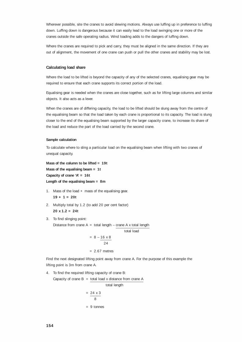
Sample calculation
To calculate where to sling a particular load on the equalising beam when lifting with two cranes of
unequal capacity.
Mass of the column to be lifted = 19t
Mass of the equalising beam = 1t
Capacity of crane ‘A’ = 16t
Length of the equalising beam = 8m
1. Mass of the load + mass of the equalising gear.
19 + 1 = 20t
2. Multiply total by 1.2 (to add 20 per cent factor)
20 x 1.2 = 24t
3. To find slinging point:
Distance from crane A = total length – crane A x total length
total load
= 8 – 16 x 8
24
= 2.67 metres
Find the next designated lifting point away from crane A. For the purpose of this example the
lifting point is 3m from crane A.
4. To find the required lifting capacity of crane B:
Capacity of crane B = total load x distance from crane A
total length
= 24 x 3
8
= 9 tonnes

155
5. To ensure that each crane is lifting its correct share of the load calculate the actual load on each
crane without the 20 per cent factor.
Crane A = load x distance from crane B
total length
= 20 x 5
8
= 12.5 tonnes
Crane B = load x distance from crane A
total length
= 20 x 3
8
= 7.5 tonnes
Use the load gauge check to ensure that each crane is lifting its correct share of the load.
Directing a multi-crane lift
When directing a multi-crane lift, observe the following rules:
• assess the weather conditions and make sure the lift is conducted during stable low wind conditions
• ensure that all crane hoist ropes remain vertical at all stages
• only one motion should be undertaken at a time
• avoid slewing movements wherever possible
• use luffing up in preference to luffing down
• ensure all crane movements are carried out at slow speeds
• where available, use appropriate instruments to monitor the angle of the load, how vertical the rope
is, and the force in each hoist rope
• in pick-and-carry operations, make sure the axis of each crane remains fully aligned with each other
• where you cannot observe all necessary locations, post dogmen or riggers to observe and report on
the progress of the lift.
Crane ‘A’(SWL 16t)
Crane ‘B’(SWL 8t)
Column (19t)
3m 5m

156
Chapter 19 Demolition rigging
Introduction
The practical skills needed to carry out rigging work associated with demolition are essentially those used
in general rigging. However, the rigger involved in this type of work must have a thorough understanding
of the additional precautions and rules of thumb needed to safely carry out the rigging operations.
Typical demolition rigging includes the dismantling of lift cars, the cutting and removal of large structural
beams and the use of winches to fell columns, walls and towers.
In some States, the person with overall responsibility for the demolition of certain types of buildings and
structures must be licensed as a demolisher with the regulatory authority. If in doubt, check with the
local authority.
Certification
The person carrying out, or directly supervising rigging work in connection with the demolition of
structures must hold an Intermediate Rigging certificate (or equivalent old certificate).
Cranes and rigging gear used in demolition
All power cranes used for hoisting and lowering demolished material must be fitted with a load weight
indicator and a hoist limiting (anti two block) device.
A crane which has been used for lifting products of demolition or for swinging-ball demolition must be
thoroughly inspected before being returned to general duties.
Flexible steel wire ropes used as felling ropes must have a minimum diameter of 12mm.
Grade 80 chains used as felling chains must have a minimum diameter of 8mm.
Estimating loads and forces in demolition rigging
The actual loads and forces applied to cranes, winches and rigging gear in demolition work are much
more difficult to assess than in general rigging.
In demolition things are not always as they seem to be, so nothing should be taken for granted. The
weight of particular structural members is often uncertain, the centre of gravity may not be as it appears
and long term deterioration may have reduced their strength or the strength of their connections.
Structural members are often subjected to unknown forces caused by the structure shifting out of
alignment, poor fabrication or poor construction methods.
Wherever practicable, test samples should be cut and weighed using the crane’s load weight indicator.
This will help to make your loading estimates more accurate.
All load estimates of in-situ members and materials must be increased by 50 per cent when calculating
the SWL for cranes, winches, and all rigging gear. This means the SWL must always be at least 1.5 times
the estimated loads.
For example, a crane with a load chart rating of 15t at a given radius must not be used to lift a load
estimated at anything greater than 10t. If a pair of slings is fixed to a beam with an estimated weight of
6t, the sling assembly must have a SWL of at least 9t.
157
Cutting and removal of beams
Large structural beams are often demolished by slinging them to a crane, winch or chainblock and then
cutting them free with cutting torches (gas axes).
There are several dangers with this type of operation if it is not carefully planned and controlled. The
freeing of a beam end may cause sudden impact loading on the crane or other rigging gear. When a beam
end is cut free, it will often suddenly and violently spring in an unexpected direction. A freed beam may
suddenly tilt because its centre of gravity is not where the rigger thought it was.
The risks involved in cutting and removing beams can be minimised if the rigger observes the
following rules:
• to allow for unusual centres of gravity, use long slings so that they can be fixed as far apart as
possible while maintaining a narrow angle between the sling legs. Alternatively, use a spreader beam
• when a crane is used, position it so it can take the load at the minimum possible radius. This will
help to prevent a swinging beam taking the crane out of its safe operational radius
• before a beam end is cut free, it should be secured with temporary guys (such as fibre ropes and
tackles) to control unexpected springing or shifting out of level
• make sure the crane or other lifting devices have slowly taken up the slack on the slings before the
beam is cut through. This will reduce impact loading and uncontrolled movement
• make sure everyone who is not needed during the operation is kept out of the area. No one should
ever be below the beam during the cutting and removal
• make sure the person cutting the beam is safely supported, has the necessary PPE and is positioned
so that if the beam springs, they will not be struck or jammed
• after the first end is cut, make any necessary adjustments to the rigging system before directing the
second end to be cut. Never cut both ends at the same time
• keep a close check on the adjacent structural members throughout the operation for any sign of
unexpected movement or overstressing. If this is apparent, cease the operation immediately,
remove everyone from the area and immediately report the situation to the person supervising
the demolition project.
Felling with winches, ropes and chains
One form of demolition rigging is felling columns, walls and towers by pulling them over. Winches which
can be used for this type of work include electrically or pneumatically powered general purpose winches,
truck or crane mounted power take off winches and manually powered winches, including drum types and
creeper types. Tracked mobile plant may also be used to pull felling ropes and chains.
Ropes, chains, shackles and other load bearing gear must be carefully inspected for damage before each
use. Unserviceable equipment can easily result in failure under load, causing the hauling rope to whiplash
dangerously or structural collapse to occur in an uncontrolled or unintended manner.
General guidance
Make sure there is sufficient clear space in the direction of collapse to contain all collapsing material
within the site confines.
Check that the area where the collapsing materials will fall is strong enough to withstand the impact
without collapsing. When in doubt, seek advice from the person supervising the demolition project.

158
Make sure the collapse will occur well clear of all site personnel and will not be fouled by any
obstructions.
Check that the winch is correctly aligned to the load so that it will pull the structure in the
intended direction.
Check all winch anchorages and fixings to ensure they will safely take the estimated loads and prevent
movement of the winch. Vehicle mounted winches should be set up on a hard, level surface. Vehicle
brakes should be applied and wheels chocked. Additional means of securing the vehicle may also
be needed.
Never fell structural members by snatch loading. Always apply the tension gradually.
Make sure all sharp edges are covered to prevent damage to hauling ropes and slings.
Make sure the horizontal distance from the winch to the demolition work is at least 1.5x the vertical
distance from the winch to the highest part of the structure to be felled.
Once pulling has started, no one must be closer to the sides of the rope or chain than three quarters of
the horizontal distance from the winch to the load.
Once the collapse has been completed, make sure the slings, hauling rope and other gear involved in the
operation are carefully inspected for signs of overstressing or damage.
Reinforced concrete columns
The following procedure should be used for freestanding square or rectangular reinforced
concrete columns:
1. secure the ropes or chains around the top of the column. Use a fixing method which will ensure they
don’t become dislodged at any stage of the pulling
2. remove the concrete cover on all sides of the base of the column and enough to expose the vertical
reinforcing bars
3. cut through all exposed reinforcing bars, except those closest to the direction of fall
4. steadily apply tension to the felling ropes or chains so the column hinges over on the uncut reinforcing
bars
5. when the column has been felled, cut the remaining reinforcing bars.

159
Masonry walls
The following procedure should be used for long masonry walls:
1. where necessary subdivide the wall into separate panels small enough for the capacity of the winch
and rigging equipment. This can be done by cutting vertical slots through the wall
2. the felling ropes or chains should be attached to the wall panels at a height no more than half the
unsupported height above the intended cut off level. Strongbacks such as C-section channels may be
needed to ensure that all of the panel is felled in a single operation
3. attach felling ropes or chains to all of the subdivided panels before starting to demolish any of them.
Make sure all free ends are left at a safe distance from the wall. This avoids the need for anyone to
approach the wall once the demolition of the panels has started
4. fell each panel separately
5. once all panels have been felled, remove the ropes or chains.
Concrete walls
Cast-in-situ reinforced concrete walls of 200mm or more thickness usually have two reinforcing grids; one
in each face. Walls with two grids can be felled in the same way as reinforced concrete columns.
Walls less than 150mm thick generally have only one reinforcing grid. This may be centrally located or
towards one face. For walls with one grid, its location should be determined at the cut off level.
Walls with only one grid should be felled in the same way as masonry walls, with the reinforcement cut
after the wall is lying flat. Walls with a single grid which is close to one face should be felled towards the
reinforced face.
Tilt up panel structures
Buildings which have reinforced precast panel walls, including tilt up panel types, should be dismantled in
the reverse sequence to their original erection.
Do not commence the dismantling and removal of wall panels until the nature and condition of their
fixings to the rest of the structure and of the jointing between panels has been determined.
Where the wall acts as bracing to other parts of the structure, temporary replacement bracing must be
installed prior to removal of those wall panels.
If the original inserts are intended to be used to lift and lower a wall panel, a careful examination of their
condition and the condition of the surrounding material must be made. If there is any doubt regarding
their adequacy, use another slinging method or provide back up slings.
Multistorey buildings
During the demolition of multistorey buildings, rigging may be needed to provide temporary support
or bracing to parts of the structural framework to maintain stability at particular stages of the
demolition process.
In general, free standing columns and walls above floor levels are to be demolished before demolition of
the floor.
160
Precast wall panels
Where the building facade incorporates precast wall panels, the relevant guidance given above for tilt-up
panel structures should be followed.
Lifts
When demolishing a lift use the following procedure:
1. support the lift car by shoring or other suitable means so that it is independent of its hoisting cable
2. make sure all lift door openings are barricaded
3. check that electrical power to all areas of the lift machinery has been disconnected
4. do not allow lift counterweights to free fall from the upper levels. Where applicable, lower
counterweights to a convenient level before disconnecting them
5. unwind lift cables in a controlled manner
6. before removing lift machinery and lift cars, make sure protection decks have been installed in the lift
shaft at not less than the two levels immediately below the work.
Lattice towers and masts
Where electricity transmission line towers are to be demolished, the transmission-line cables must first
be deactivated and then removed in a way which prevents unbalanced lateral loading on the tower at the
cable attachment points.
Caution: Suspended cables must not be cut under any circumstances.
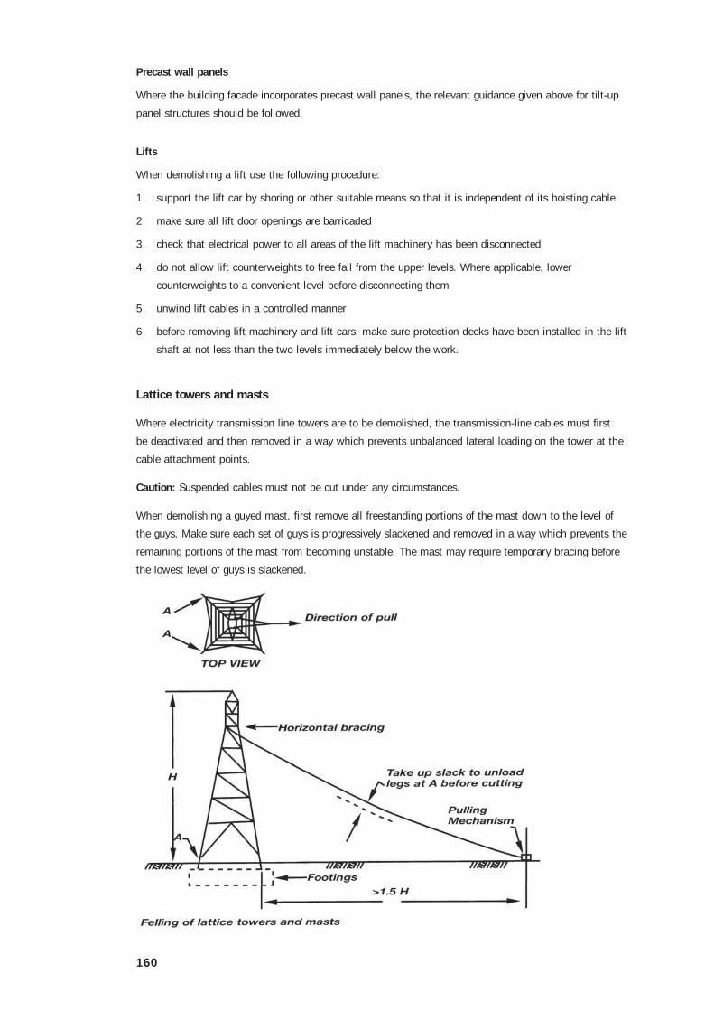
When demolishing a guyed mast, first remove all freestanding portions of the mast down to the level of
the guys. Make sure each set of guys is progressively slackened and removed in a way which prevents the
remaining portions of the mast from becoming unstable. The mast may require temporary bracing before
the lowest level of guys is slackened.
161
Felling unguyed towers and masts
Attach the ropes or chains to node points incorporating horizontal bracing near the top of the structure.
Position the winch at right angles to the face of the structure nearest the direction of fall.
Before cutting any member, tension the hauling rope enough to relieve the dead load from the furthest legs
of the structure.
While maintaining the tension on the hauling rope, have the back legs of the structure cut through or
disconnected near ground level.
As soon as possible after the back legs are freed, remove all personnel and equipment from the area
around the structure. Make sure the tension on the hauling rope is held steady and not increased until
everyone is out of the area.
Felling can now continue. Disconnect the remaining legs from their footings after the felling has
been completed.
Pre-stressed concrete members
Riggers involved in the demolition of reinforced concrete structures need to be able to recognise
pre-stressed structural members and understand the special hazards associated with their removal.
Pre-stressing is used to provide concrete members with a far greater load-bearing capacity than similar
sized normal reinforced members.
Pre-stressed members will not be found in structures built before 1950. Buildings built between 1950 and
1960 may have pre-stressed floor sections. Structures built after 1960 may include major pre-stressed
structural members.
Pre-stressing methods
Pre-stressed structural members have tendons embedded along their length. These tendons are stretched
before the member is placed into service so it can take the loads of the structure.
The tendons may be high tensile wires from 5mm to 7mm in diameter arranged singly or in groups, high
tensile steel cables 9mm to 15mm in diameter arranged singly or in groups, or single high tensile steel
bars 19mm to 38mm in diameter with threaded ends.
Members can be pre-stressed in two basic ways. They can be pre-tensioned or post-tensioned.
Pre-tensioned members have their tendons tensioned with hydraulic jacks. The tendons are anchored in
their stretched condition before the concrete is poured. Once the concrete has cured and bonded around
the tendons, the anchorages are removed and the slack ends of the tendons are cut off flush. This method
is generally used in the construction of precast members.
Post-tensioned members are usually formed up in-situ, with the tendons lying loose in tubes or ducts
which have steel anchor plates at each end. The tendons pass through one or both of these anchor plates.
After the concrete is cured, hydraulic jacks are used to tension the tendons against the anchor plates.
Once the tensioning is complete, the ducts are pumped full of liquid cement grout under pressure. This is
intended to help bond the tendons and protect them from corrosion.

162
Unbonded tendons usually have provision for retensioning or releasing the load in the tendons. Where
pavement slabs and footing beams are directly supported on the ground the ducts may be packed with
grease, which means they remain unbonded.
Recognising pre-stressed members
Pre-stressed members can often be easily identified by their length, slenderness or camber.
Most concrete beams with spans greater than 9m and slabs with spans greater than 8m will be
prestressed. Suspended pre-stressed members are usually more slender than normally reinforced
members. Precast floor sections that have been pre-stressed will often have a slight upward camber.
Post-tensioned members generally have a surface recess on one or both ends to allow the tendon
anchorages to be protected with a mortar covering. This covering is usually a different colour to the
concrete and hairline cracks are frequently visible around the recess.
The cut ends of pre-tensioned tendons are usually covered with a protective cement render. Light
scabbling of the rendered face should reveal their presence.
Hazards
The demolition of structures incorporating pre-stressed members can be very hazardous. The rigger
responsible for the slinging and removal of pre-stressed members must be aware of the potential problems
so that the rigging method selected can prevent them from occurring.
Post-tensioned members with unbonded or badly bonded tendons are the most dangerous. If a tendon is
cut or an anchor plate is damaged, the member may suddenly lose its strength and collapse. This can be
prevented by propping under the entire length or area before any tendon is cut.
There are also several other dangers which are often beyond the rigger’s competence to identify and
control. Therefore, ungrouted post-tensioned members should never be demolished without consulting a
structural engineer or the supplier of pre-stressing equipment.
Maintain the orientation of the beam when pre-stressed beams are removed. The beam has been stressed
to take load, including its own selfweight, in a particular direction. If the beam is turned over or upside
down, the forces in the beam will be acting in a different way. This may be enough to cause sudden and
catastrophic collapse of the beam.
The structure above any post-tensioned transfer beam should not be demolished without consulting a
structural engineer or the supplier of pre-stressing equipment. Unless special counter measures are taken,
the demolition and removal of the upper floors and the consequent reduction in the imposed loads can
cause the transfer beams to fail and may even trigger a collapse of the entire structure.
Unattended free standing structural members
The stability of partially demolished structures can be severely affected by high winds and heavy storm
conditions. Therefore the planning and control of the demolition sequence must ensure that freestanding
elements of the structure are not left in a hazardous condition when work ceases.
The following general rules should be observed:
• a freestanding masonry wall must not be left outside working hours without lateral support if its
height is greater than 15 times its least overall plan dimension

163
• a freestanding reinforced concrete column must not be left outside working hours without lateral
support if its height is greater than 20 times its least overall plan dimension
• a freestanding uncased steel column must not be left outside working hours without lateral support if
its height is greater than 25 times its least overall plan dimension.
Further information
Further information can be found in AS 2601 – The demolition of structures and AS 2550.1 Cranes –
Safe use, Part 1: General requirements. Codes of practice dealing with demolition work may be approved
for use in some States and Territories. Specific regulations dealing with demolition may also apply. If in
doubt, check with the local regulatory authority.

164
Chapter 20 Rigging cranes and hoists
Certification
An Intermediate Rigging Certificate or old equivalent, is necessary to perform the rigging of:
• external guided cantilevered platform (personnel and materials) hoists
• hoists with jibs
• self climbing hoists
• mobile crane booms
• tower cranes.
Cantilevered platform (personnel and materials) hoists
The cantilevered platform (personnel and materials) hoist is the most commonly used hoist in the
construction industry. It uses a rack and pinion driven by at least two electric motors to raise and lower
the platform.
Cantilevered platform personnel and materials hoists
165
Setup
When the cage is at the top landing there must be no less than 1.5m to the top of the rack. When the
cage is stopped by the final stopping devices there must be no less than 1.2m to the top of the rack.
The final section (or tower module) must be fitted above the top section of rack and must not be less than
1.5m in height. The final section must not be fitted with a rack.
When the cage is sitting at its lowest point on fully compressed buffers there must be at least 600mm
between the underside of the cage and the floor of the pit.
The landings and the inside of the cage must have effective protective mesh fixed to a steel pipe or angle
iron frame work.
Door entrances must have at least 2m overhead clearance. Doors must have 9mm square, 2.5mm wire
mesh over a steel frame. The doors must not deflect more than 25mm under forces exerted in normal
working conditions. (1kg over 1m2)
Doors must be no more than 150mm from the edge of a landing. They must fit flush with the surrounding
mesh enclosure to form an effective guard. The clearance between the floor of the cage and the landing
must not be greater than 50mm.
Car construction
Cars must have a steel frame and be fully enclosed on the sides, top and gates. It must not deflect more
than 25mm under forces exerted during normal working conditions.
The gate ends and the sides must be covered with steel or timber up to 1.2m. Above this must be
covered by 30mm square, 3mm steel wire mesh. If there is less than 100mm from the cage to
moving parts the mesh size must be 10mm square.
The gate in the cage must sit fully within the floor line of the cage and the door counterweight must have
an enclosure to slide into. The cage must measure no less than two metres from the floor to the ceiling.
The car roof has a hinged trap door with an electrical interlock. It must be strong enough to withstand
material falling from above. There must be a ladder inside the cage at all times to provide access to
the trapdoor.
Lighting
The cage must have lighting that allows for safe operation and maintenance of the hoist. In addition to the
light inside the cage there must be a permanently wired hand lamp for use on the roof. There must also
be an emergency light that will operate in the event of the failure of the main light.
Load plate
A load notice plate must be displayed in the cage with the following details:
Maximum Load Capacity
Materials kg
Passengers kg
Combined materials & passengers kg

166
Car door and landing interlocks
There must be a gate on each floor fitted with a lock which can only be released from inside the car.
Each door must be interlocked so that the hoist will not operate unless all doors are closed and locked.
Locks must be enclosed by metal cladding, be weatherproof, fail safe and bolted to the door frame.
The gate on the lowest landing can be opened by key by the hoist operator from the landing, if the cage is
within 230mm of the landing.
Working limit switches at the top and bottom prevent the cage overrunning. Limit switches must be metal
clad and weatherproof and the cams must be constructed of steel.
In the event of failure of the working limits there is also a full current limit switch which will cut
off all power to the hoist if the hoist travels beyond the top or bottom landing.
If any of the full current limit switches are tripped they must be reset and checked by a
qualified electrician.
Electrical
All wiring must be insulated with PVC and where the wiring enters switch gear the PVC must
not be distorted.
All metal armouring for cables and other electrical equipment must be earthed by wire no less than
2.5mm2. All earth wires must return to one place and be clamped together.
If an earth fault does occur the control current wiring must be arranged so that the power to the
hoist is cut off.
The control fuse must have the maximum current capacity clearly marked. Fuses must be replaced by a
qualified electrician.
Roof controls
Roof controls must be used by riggers or other authorised persons only. Hoist controls must be shrouded
to prevent accidental activation of the manual reset emergency stop button.
The controls inside the cage must be inoperative when the roof controls are in use. When the hoist
is operated from the roof for maintenance or repairs the controls must be switched over to the
installation setting.
Pre-checks
Prior to operating a hoist for repairs or maintenance carry out the following pre-checks:
• make sure that there are no obstructions such as pipes in the path of the hoist platform
• make sure that the lift car alarm and communication system are functioning
• take the hoist on a check run to check the operation of the stopping limits. Show caution when
approaching the top or bottom landings
• test the operation of all gates including the trap door. Make sure that the hoist will not operate while
the trap door or any of the gates are open
167
• make sure that the rack and pinion are well greased and that the teeth are in good order
• the switch that controls the operation of the cage must be inside the cage and return to the stop
position when it is released, although control may be switched to an alternate switch on the roof
for rigging uses.
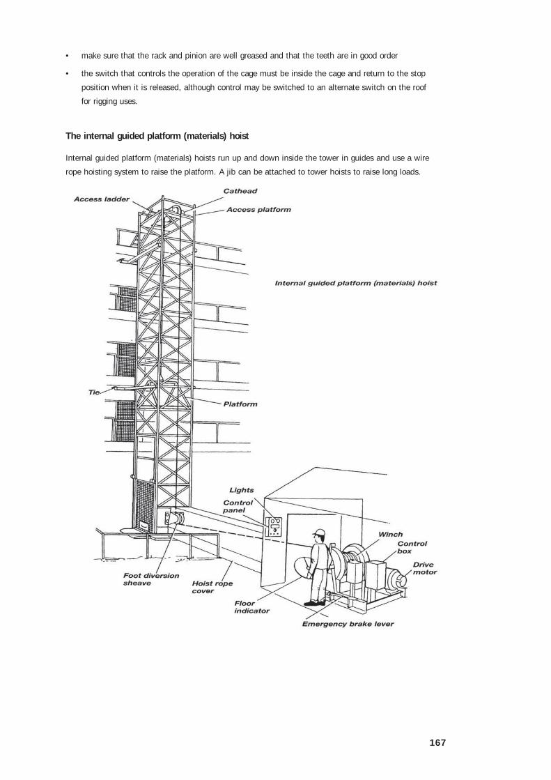
The internal guided platform (materials) hoist
Internal guided platform (materials) hoists run up and down inside the tower in guides and use a wire
rope hoisting system to raise the platform. A jib can be attached to tower hoists to raise long loads.

168
There are two types of tower hoist:
• internal guided platform (materials) hoist
• superduty tower hoist.
The platform is hoisted and lowered inside the tower and held in position by two timber or steel guides.
The platform is hauled up and down by a wire rope that runs up the tower over a sheave system and
down to the platform.
The tower is encased in wire mesh to prevent people being hit by the moving platform. There are openings
at each floor to gain access to the platform which are guarded by gates or barriers. There is a signalling
system so that people on other levels can communicate with the driver.
Tower set up
The tower must be tied to the building or guyed to the ground every 9 metres. There must be no more
than 6m free standing between the top guy or tie and the top of the tower.
Guys must extend from the corners of the tower. They must be at least 12mm diameter and 6 x 19
construction FSWR. Fibre rope must not be used.
There must be access to the top platform for maintenance of the rope sheaves. The area must have
securely fixed closely boarded 38mm planks and be enclosed by a 1m high handrail.
An inclined ladder must provide access to the top platform. Ladders between the landings must not be
more than 6m.
The tower must be completely enclosed by 1.2mm wire – 50mm mesh up to 1.8metres in height, 20 mm
closely boarded timber or light gauge steel sheet.
The gap between the edge of the platform and the inside of the tower must not exceed 50mm. The timber
runners or guides must be at least 100mm x 75mm oregon or hardwood. They must be bolted to each
horizontal brace and to the cat head bearers.
The runners and corner posts must rest on a steel plate of at least 300mm x 50mm. It must be secured
with countersunk bolts.
Gates
If the hoist is serving higher than three storeys, gates and lights must be installed on each floor. Gates
must be at least 1.8 metres high and made of 2.5mm wire, 50mm mesh.

169
Gates can hinge outward or slide horizontally or vertically. They must have a fixed stop to prevent them
closing beyond the correct position and an effective latch to make sure that they remain closed.
All gates must be wired so that when any gate is open, two red lights will show at the driving station and
when all the gates are closed, one green light will show.
Hoist winch
The hoist rope runs from the winch drum under the first lead sheave at ground level up to the top of the
tower and then down to the platform.
The rope will not lie neatly onto the winch drum unless the correct ‘fleet’ angle is formed from the foot
diversion sheave to the outside of the drum from the centre of the drum. (The first lead sheave on a tower
hoist is called the foot diversion sheave.)
There must be a covered guard-rail on both sides of the length of hoist rope between the winch drum and
the first lead sheave. When the hoist takes the strain the rope can whip violently.
The nip point of the lead sheave must also be guarded to prevent a person in contact with the rope being
drawn into the sheave. The anchor point for the foot diversion sheave must not put bending forces on
the tower.
The winch must be secured to a frame to prevent it slipping forward. Alternatively two 150mm x 100mm
shores can be placed between the winch and the tower.
Concrete hoppers should not be supported by the hoist tower.
170
Working load limit
The combined weight of the load and the platform for standard internal guided platform tower hoists must
not exceed 1t.
Typical loads:
A wheelbarrow of concrete weighs up to 250kg.
A wheelbarrow of bricks weighs up to 216kg (45 bricks).
A pallet load of bricks weighs up to 2t.*
* Combined with the weight of a forklift truck a pallet of bricks is too heavy for any materials only hoist.
Always check the combined weight.
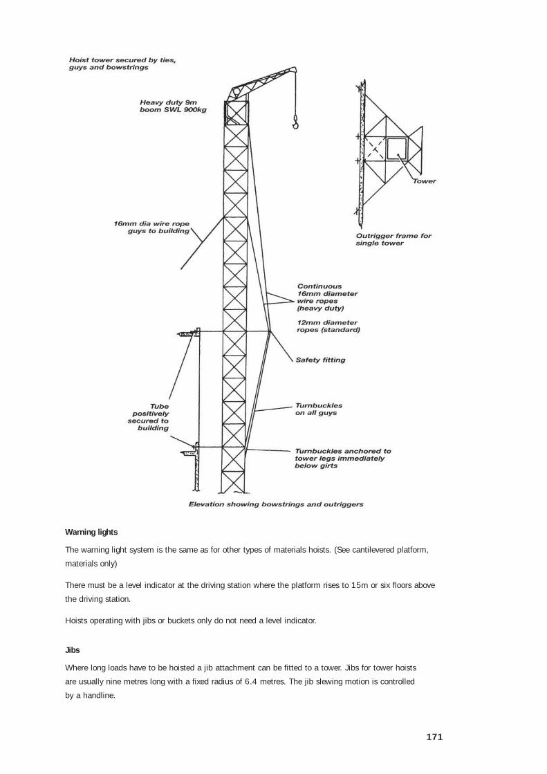
Super duty tower hoists
Super duty tower hoists meet the need for a hoist with a greater load carrying capacity. The towers can be
erected to a height of 150m. They have a 2.5t capacity and some have dual towers.
Dual towers can be erected so that there is a concrete tipping bucket in one tower and a platform in
the other.
Tower set up
Towers must be fully braced against the building and must not exceed 75m where guy ropes
only are used.
Towers more than 75m must be braced every 16m starting from the base. Towers of 75m or less must be
guyed from each corner with 16mm diameter, 6 x 19 FSWR every 16m.
A tower must not project more than 18m above the top of the building. The projecting section of tower
must be guyed in all directions.
Tube 89mm x 4.88mm must be used for towers up to 107m in height. Above 107m, the lower section
must be constructed of 89mm x 5.9mm tube.
The tower structure must be of 2m high panels, 2.4m x 1.9m. Dual towers are 4.9m x 1.9m.
The section of the lower tower where the foot diversion sheave is attached must be 89mm OD hydraulic
tube. It is usually painted yellow and branded FS.
Hoisting system
The hoist rope for a super duty hoist must be 20mm, ordinary lay and at least 1570 grade FSWR.
Protective barriers
The requirements are the same as the standard tower hoist.
171
Warning lights
The warning light system is the same as for other types of materials hoists. (See cantilevered platform,
materials only)
There must be a level indicator at the driving station where the platform rises to 15m or six floors above
the driving station.
Hoists operating with jibs or buckets only do not need a level indicator.
Jibs
Where long loads have to be hoisted a jib attachment can be fitted to a tower. Jibs for tower hoists
are usually nine metres long with a fixed radius of 6.4 metres. The jib slewing motion is controlled
by a handline.
172
Do not use the jib when there is a load on the platform or bucket or when the platform is off the ground.
Do not use a jib to drag or snig loads.
Single tower (2.4m x 1.9m) WLL
A single super duty tower hoist can raise 2.5 tonnes up to 150 metres.
The platform weighs 600kg.
Therefore the SWL = 1.9 tonnes.
Dual tower (4.8m x 1.9m) WLL
Where both towers of a dual tower hoist are in use the SWL of each is 1.2 tonnes.
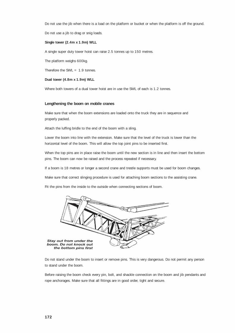
Lengthening the boom on mobile cranes
Make sure that when the boom extensions are loaded onto the truck they are in sequence and
properly packed.
Attach the luffing bridle to the end of the boom with a sling.
Lower the boom into line with the extension. Make sure that the level of the truck is lower than the
horizontal level of the boom. This will allow the top joint pins to be inserted first.
When the top pins are in place raise the boom until the new section is in line and then insert the bottom
pins. The boom can now be raised and the process repeated if necessary.
If a boom is 18 metres or longer a second crane and trestle supports must be used for boom changes.
Make sure that correct slinging procedure is used for attaching boom sections to the assisting crane.
Fit the pins from the inside to the outside when connecting sections of boom.
Do not stand under the boom to insert or remove pins. This is very dangerous. Do not permit any person
to stand under the boom.
Before raising the boom check every pin, bolt, and shackle connection on the boom and jib pendants and
rope anchorages. Make sure that all fittings are in good order, tight and secure.

173

174
Tower cranes
Tower cranes are widely used in the construction of multi-storey buildings and high rise industrial projects.
There are two main types of tower crane:
• luffing boom
• hammerhead.
Both of these can be climbing, fixed or rail mounted. Climbing tower cranes can be internal or external to
the building structure. Fixed and rail mounted cranes do not climb.
The most common type of tower crane used in Australia is the luffing boom type which can be either rope
assisted hydraulic luffing type or entirely rope luffing. They are usually powered by diesel motors mounted
on the machine deck at the top of the tower.

175
The hammerhead crane which has a horizontal jib is less common in Australia but widely used in Europe.
They are usually powered by electric motors and have a crab which travels along the jib to achieve the
required radius.
Tower crane design should comply with AS 1418.4 Tower cranes and designs must be registered with a
State or Territory regulatory authority. Each individual tower crane must also be registered.
The addition or removal of sections of external climbing tower cranes must be carried out by riggers with
an Intermediate Rigging Certificate (or old equivalent). The complete erection and dismantling of tower
cranes is done by rigging crews who have undertaken specialist training in particular types of crane.
General safety
Tower cranes consist of a square tower which is bolted to a concrete foundation, support beams or a rail
carriage. The slewing platform, hoist, mast and jib are mounted on the tower. For external climbing the
climbing frame is fitted around the top of the tower. For internal climbing the rams and beams are fitted
within the base of the tower.
All potential hazards should be considered before erecting a tower crane on site. The installation of
the crane should be well planned and carried out in accordance with the manufacturer’s instructions.
The sequence of installing the jib (or boom) sections and counterweights is critical. Using an incorrect
sequence could result in a collapse.
Engineers consider the type of soil and rock under the crane, the crane’s capacity and various radii before
deciding on the exact site.
There is a maximum free standing height which is designed by the manufacturer. This should not be
exceeded without the manufacturer’s and engineer’s approval.
During the erection, climbing or alteration of a tower crane the following rules should be observed:
• use barricades or other effective means to prevent unauthorised access to the operational zone
• use lanyards to restrain tools when working at height
• use a safety harness whenever there is a risk of falling

176
• make sure the each boom connection pin is fitted with chain or wire rope attached to both the boom
and the pin head
• the effects of windloading must be taken into account including the funnelling effects between
adjacent buildings. Large sections of tower cranes should only be handled in calm conditions
• the sequence of erection and dismantling must be carried out in strict accordance with management’s
instructions
• tower erection bolts must be of the type specified by the manufacturer and be correctly torqued to
their recommendations
• all loose tools, nuts and bolts must be removed from the crane or effectively stored after erection and
before operation.
External climbing tower cranes
External climbing tower cranes are self climbing and are tied to the building or structure and are climbed
by adding sections to the top of the tower. Riggers must know how to add and remove the tower sections.
Use the sequence below as a general guide:
1. when adding sections unload and place sections close to the crane at the foot of the tower so there is
no need to slew the crane to pick up another section
2. install the monorail if it is not already in place
1. Crane lifts additional tower section and suspends it from extendable monorail. Bolts of top tower section are removed at A.
2. Hydraulic ram lifts top section of crane and climbing frame.
3. Additional tower section is drawn into the climbing frame and bolted at B and A.
To climb down, the reverse procedure is followed.

177
3. connect the climbing hoses from the climbing control on the machine deck to climbing rams in
climbing frame. Take directions from the fitter as it may be necessary to stop the engine.
Slewing motions may not be available during the climbing process, because some cranes use the slew
pump to supply the necessary oil pressure for the climbing rams. This is a simple matter of taking the
slew hoses off the slew motor and fitting them to the climbing rams controlling the oil flow with the
slew control
4. lift the section and hang it on the monorail by transferring from the crane hook onto a four legged
sling attached to the trolley on the monorail. Ensure that the sling legs are the correct and equal
length so that the section can run freely when pulled into the aperture at the correct height
5. lock the counterweights and make sure that the jib is right up
6. remove the tower section bolts and ensure that the fitter has connected hoses before trying to climb
7. the rigger in charge must direct the driver to balance the crane by luffing the jib out or travelling the
crab. The driver should make note of the radius or crab position so it is possible to return to this point
8. the crane is now ready to climb. The rigger in charge, the dogman controlling the climbing valve and
the driver in the cabin in charge of the throttle must all be in radio contact
9. at the signal, ‘rams down’ the crane will start to lift. The tower sections may jam in the climbing
frame. It may be necessary for riggers to adjust the guides in the climbing frame several times during
climb to ensure the frame slides freely over tower sections. Do not simply increase pressure to force it
through
10. once the crane has reached the full extent of the rams (full climbing height), the section can now
be pulled into the space and bolted into place. Please note: on some cranes raising the tower to the
required height will need four climbing cycles of the rams
11. the rams are then retracted to protect the piston shafts, keep them out of the way and return oil to
the reservoir
12. once retracted, disconnect the hoses if necessary and coil them out of the way on the machine deck
(usually under hoist drum)
13. counterweights can now be reconnected and the limits reset if necessary
14. the mono-rail may have to be removed, depending on design.
Removing a section is essentially the reverse of the above sequence.

178
Internal climbing cranes
Internal climbing cranes sit in the lift well, stairwell or in a well especially designed into the building. The
climbing and erection method of the crane is designed into the building because a working crane subjects
the building structure to great stresses.
1. The telescopic sections of beams A and C are retracted.
2. Crane, tower and climbing frame, to which beams A and C are attached, are lifted by hydraulic rams.
3. Telescopic sections of beams A and C are extended to support the crane. Telescopic sections of beams B are retracted. Hydraulic cylinders lift beam B to the level of beams A and C. Telescopic sections of beam B are extended.
Engineers’ certificates must be checked to ensure that floors are of sufficient strength to take the total
weight of the crane, the support structure and all loadings imposed by the crane working.
If the lift shaft is not used, the floor reinforcing is left protruding through the cut out section of the floor.
The hole can later be formed up and poured, sealing the hole after the crane is raised higher.
The tower sits inside the building (typically 5 or more sections in the building) as the building is erected
around the crane. The crane is jacked up from the floor it is sitting on by extending the climbing rams
pushing the completed crane up. When the bottom of the tower reaches the required height (usually the
next floor or a level cast into the lift well), flippers (feet) are pushed out and the crane is settled on to its
new level. Rams are then retracted and settled on to the same floor ready for next climb.
When the crane is sited in the lift well, holes to take the flippers and beams are cast into the walls of the
lift or stair well as part of the design of the building.
Internal climbing cranes are usually taken down from the roof or top slab by a special recovery crane or by
large mobile cranes. Removal of the tower crane should be planned before erection begins.
Please Note: As a result of a tower crane fatality on 5 August 2001, WorkSafe Victoria has issued two
Alerts setting out additional requirements to be observed for the jumping of luffing boom tower cranes that
incorporate sliding counterweights. These are:
• Alert 6/2001, Precautions in Jumping Tower Cranes, and
• Alert 7/2001, Further Precautions in Jumping Tower Cranes.
The information contained in these Alerts is additional to the advice provided on tower crane rigging on
pages 174 to 178. They can be accessed at www.workcover.vic.gov.au