rigging and assembly instructions - evapco 1a - structural steel support on 14’ wide unit figure...
TRANSCRIPT
Rigging andAssembly Instructions
14’, 28’, 42’ & 56’ WIDE AT/UT/USSINDUCED DRAFT COOLING TOWERS
Bulletin 144Y
EVAPCO products are manufactured worldwide:
Visit EVAPCOʼs Website at: http://www.evapco.comEVAPCO...SPECIALISTS IN HEAT TRANSFER PRODUCTS AND SERVICES.
EVAPCO, Inc. — World Headquarters & Research/Development Center
EVAPCO, Inc. • P.O. Box 1300 • Westminster, MD 21158 USAPHONE: 410-756-2600 • FAX: 410-756-6450 • E-MAIL: [email protected]
EVAPCO, Inc.World HeadquartersP.O. Box 1300Westminster, MD 21158 USAPhone: 410-756-2600Fax: 410-756-6450E-mail: [email protected]
EVAPCO Asia/Pacific
EVAPCO Asia/Pacific Headquarters1159 Luoning Rd. Baoshan Industrial ZoneShanghai, P. R. China, Postal Code: 200949Phone: (86) 21-6687-7786Fax: (86) 21-6687-7008E-mail: [email protected]
EVAPCO Europe
EVAPCO Europe, N.V.European HeadquartersIndustrieterrein Oost 40103700 Tongeren, BelgiumPhone: (32) 12-395029Fax: (32) 12-238527E-mail: [email protected]
EVAPCO East5151 Allendale LaneTaneytown, MD 21787 USAPhone: 410-756-2600Fax: 410-756-6450E-mail: [email protected]
EVAPCO Midwest1723 York RoadGreenup, IL 62428 USAPhone: 217-923-3431Fax: 217-923-3300E-mail: [email protected]
EVAPCO West1900 West Almond AvenueMadera, CA 93637 USAPhone: 559-673-2207Fax: 559-673-2378E-mail: [email protected]
EVAPCO Iowa925 Quality DriveLake View, IA 51450 USAPhone: 712-657-3223Fax: 712-657-3226
EVAPCO IowaSales & Engineering215 1st Street, NEP.O. Box 88Medford, MN 55049 USAPhone: 507-446-8005Fax: 507-446-8239E-mail: [email protected]
EVAPCO Newton701 East Jourdan StreetNewton, IL 62448 USAPhone: 618-783-3433Fax: 618-783-3499E-mail: [email protected]
EVAPCO-BLCT Dry Cooling, Inc.981 US Highway 22 WestBridgewater, New Jersey 08807 USA Phone: 1-908-379-2665E-mail: [email protected]
Refrigeration Valves & Systems CorporationA wholly owned subsidiary of EVAPCO, Inc.1520 Crosswind Dr.Bryan, TX 77808 USAPhone: 979-778-0095Fax: 979-778-0030E-mail: [email protected]
McCormack Coil Company, Inc.A wholly owned subsidiary of EVAPCO, Inc.P.O. Box 17276333 S.W. Lakeview BoulevardLake Oswego, OR 97035 USAPhone: 503-639-2137Fax: 503-639-1800E-mail: [email protected]
EvapTech, Inc.A wholly owned subsidiary of EVAPCO, Inc.8331 Nieman RoadLenexa, KS 66214 USAPhone: 913-322-5165Fax: 913-322-5166E-mail: [email protected]
Tower Components, Inc.A wholly owned subsidiary of EVAPCO, Inc.5960 US HWY 64ERamseur, NC 27316Phone: 336-824-2102Fax: 336-824-2190E-mail: [email protected]
EVAPCO Europe, S.r.l.Via Ciro Menotti 10I-20017 Passirana di RhoMilan, ItalyPhone: (39) 02-939-9041Fax: (39) 02-935-00840E-mail: [email protected]
EVAPCO Europe, S.r.l.Via Dosso 223020 Piateda Sondrio, Italy
EVAPCO Europe, GmbHBovert 22D-40670 Meerbusch, GermanyPhone: (49) 2159-69560Fax: (49) 2159-695611E-mail: [email protected]
Flex coil a/sA wholly owned subsidiary of EVAPCO, Inc.Knøsgårdvej 115DK-9440 Aabybro DenmarkPhone: (45) 9824 4999Fax: (45) 9824 4990E-mail: [email protected]
EVAPCO S.A. (Pty.) Ltd.A licensed manufacturer of EVAPCO, Inc.18 Quality RoadIsando 1600Republic of South AfricaPhone: (27) 11-392-6630Fax: (27) 11-392-6615E-mail: [email protected]
Evap Egypt Engineering Industries Co.A licensed manufacturer of EVAPCO, Inc.5 El Nasr RoadNasr City, Cairo, EgyptPhone: 2 02 24022866 /2 02 24044997Fax: 2 02 24044667/2 02 24044668E-mail: [email protected] / [email protected]
EVAPCO (Shanghai) Refrigeration Equipment Co., Ltd.1159 Louning Rd., Baoshan Industrial ZoneShanghai, P.R. China, Postal Code: 200949Phone: (86) 21-6687-7786Fax: (86) 21-6687-7008E-mail: [email protected]
Beijing EVAPCO Refrigeration Equipment Co., Ltd.Yan Qi Industrial Development DistrictHuai Rou County Beijing, P.R. China, Postal Code: 101407Phone: (86) 10 6166-7238Fax: (86) 10 6166-7395E-mail: [email protected]
EVAPCO Australia (Pty.) Ltd.34-42 Melbourne RoadP.O. Box 436Riverstone, N.S.W. Australia 2765Phone: (61) 2 9627-3322Fax: (61) 2 9627-1715E-mail: [email protected]
EVAPCO Composites Sdn. BhdNo. 70 (Lot 1289) Jalan Industri 2/3Rawang Integrated Industrial ParkRawang, Selangor, 48000 MalaysiaPhone: 60 3 6092-2209Fax: 60 3 6092-2210
EvapTech Asia Pacific Sdn. BhdA wholly owned subsidiary of EvapTech, Inc.IOI Business Park, 2/F Unit 20Persiaran Puchong Jaya SelatanBandar Puchong Jaya,47170 Puchong, Selangor, MalaysiaPhone: (60-3) 8070-7255Fax: (60-3) 8070-5731E-mail: [email protected]
EVAPCO North America
2
AT/UT/USS Cooling Towers
Figure 1a - Structural Steel Support on 14’ Wide Unit Figure 1b - Structural Steel Support on 28’ Wide Units
IntroductionThank you for purchasing your EVAPCO cooling tower, this manual will provide instructions for installation of the cooling tower. Ifyou have purchased a model UT cooling tower or USS with the Super Low Sound Fan option, please be sure to pay attention tothe proper rigging instructions for that special option enclosed herein. If any questions arise during the installation, please contactyour local EVAPCO representative or us directly at our Global Headquarters location.
International Building Code ProvisionsThe International Building Code (IBC) is a comprehensive set of regulations addressing the structural design and installationrequirements for building systems – including HVAC and industrial refrigeration equipment. As of June 2008, all 50 states plusWashington D.C. have adopted the International Building Code. The code provisions require that evaporative cooling equipmentand all other components permanently installed on a structure must meet the same seismic design criteria as the building. TheAT/UT/USS Series of Open Cooling Towers are IBC 2009 compliant up to 1g with standard construction and up to 5.12g withadditional structural modifications.
All items attached to the Evapco AT/UT/USS cooling tower must be independently reviewed and isolated to meet applicable windand seismic loads. This includes piping, ductwork, conduit, and electrical connections. These items must be flexibly attached to theEvapco unit so as not to transmit additional loads to the equipment as a result of seismic or wind forces.
Method of ShipmentAll 14’, 28’, 42’ and 56’ wide units are shipped with the top section(s) separate from the bottom section(s). These sections havemating flanges and will join together in a waterproof joint when sealed and bolted together as described in the followinginstructions. Miscellaneous items, such as sealer, screws, drip channels, splash guards and any other required materials, arepackaged and placed inside the pan for shipment. All 14’ x 26’ cells with the Super Low Sound Fan or Low Sound Fan option areshipped in (3) three sections. The fan section is shipped separate from the fill casing section.
StorageDo not place tarps or other coverings over the top of the units if the units are to be stored before installation. Excessive heat canbuild up if the units are covered, causing possible damage to the PVC eliminators, PVC louvers, or PVC fill. For extended storagebeyond six months rotate the fan and fan motor shaft(s) monthly. The fan shaft bearings should also be purged andregreased prior to start-up if it has been stored.
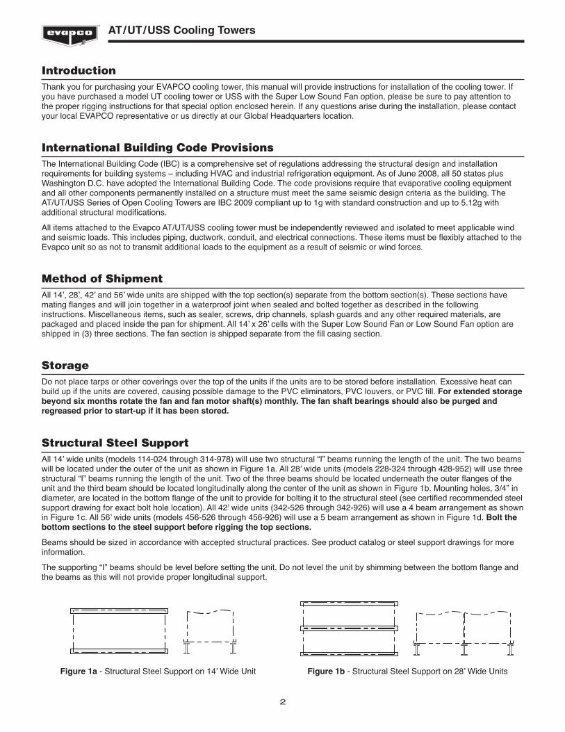
Structural Steel SupportAll 14’ wide units (models 114-024 through 314-978) will use two structural “I” beams running the length of the unit. The two beamswill be located under the outer of the unit as shown in Figure 1a. All 28’ wide units (models 228-324 through 428-952) will use threestructural “I” beams running the length of the unit. Two of the three beams should be located underneath the outer flanges of theunit and the third beam should be located longitudinally along the center of the unit as shown in Figure 1b. Mounting holes, 3/4” indiameter, are located in the bottom flange of the unit to provide for bolting it to the structural steel (see certified recommended steelsupport drawing for exact bolt hole location). All 42’ wide units (342-526 through 342-926) will use a 4 beam arrangement as shownin Figure 1c. All 56’ wide units (models 456-526 through 456-926) will use a 5 beam arrangement as shown in Figure 1d. Bolt thebottom sections to the steel support before rigging the top sections.
Beams should be sized in accordance with accepted structural practices. See product catalog or steel support drawings for moreinformation.
The supporting “I” beams should be level before setting the unit. Do not level the unit by shimming between the bottom flange andthe beams as this will not provide proper longitudinal support.

3
AT/UT/USS Cooling Towers
Rigging Bottom Section
Lifting Bottom Section
Lifting Ears are located 2/3 down on vertical posts of thebottom section for lifting and final positioning purposes asshown in Figure 2. The hook of the crane must be a minimumdimension of “H” above the top of the section being lifted toprevent undue strain on the lifting devices. See Table 1 for theminimum “H” dimension. These lifting devices should not beused for extended lifts or where any hazard exists unlesssafety slings are employed under the section. (See“Extended Lifts” on page 8 for proper arrangement.) Boltthe bottom section to the steel support before rigging the topsection.
Model No. Min. “H” Dim.
All 14’ x 24’ Cells 17 Feet
All 14’ x 26’ Cells 22 Feet
Table 1 – Minimum “H” Dimension for Bottom Sections
Figure 1c - Structural Steel Support on 42’ Wide Unit
Figure 1d - Structural Steel Support on 56’ Wide Units
H
LIFTING EARS
Figure 2 - 14’ Wide Bottom Section
Joining Multi-Cell Units Bottom Sections
Models 214-0148 through 214-1248, 314-0172 through 314-1272, 214-552 through214-952 and 314-578 through 314-978
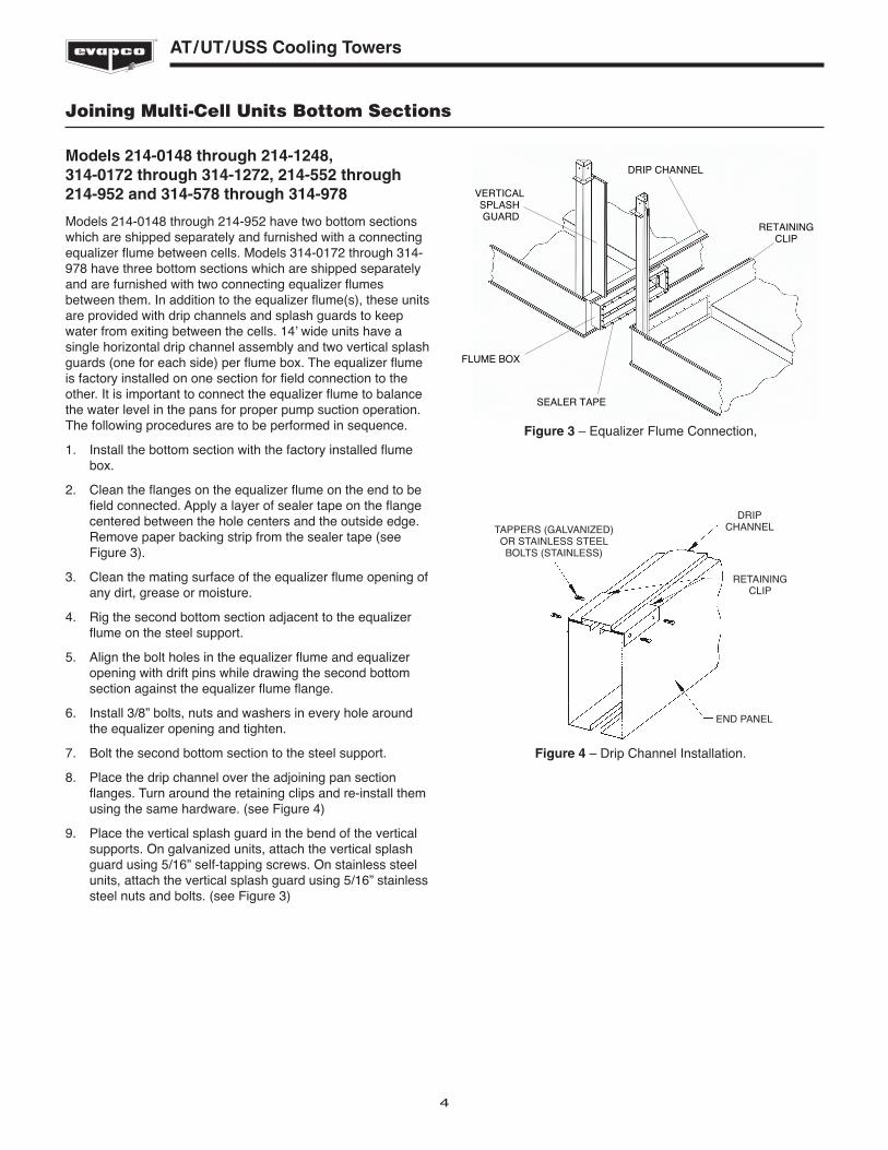
Models 214-0148 through 214-952 have two bottom sectionswhich are shipped separately and furnished with a connectingequalizer flume between cells. Models 314-0172 through 314-978 have three bottom sections which are shipped separatelyand are furnished with two connecting equalizer flumesbetween them. In addition to the equalizer flume(s), these unitsare provided with drip channels and splash guards to keepwater from exiting between the cells. 14’ wide units have asingle horizontal drip channel assembly and two vertical splashguards (one for each side) per flume box. The equalizer flumeis factory installed on one section for field connection to theother. It is important to connect the equalizer flume to balancethe water level in the pans for proper pump suction operation.The following procedures are to be performed in sequence.
1. Install the bottom section with the factory installed flumebox.
2. Clean the flanges on the equalizer flume on the end to befield connected. Apply a layer of sealer tape on the flangecentered between the hole centers and the outside edge.Remove paper backing strip from the sealer tape (seeFigure 3).
3. Clean the mating surface of the equalizer flume opening ofany dirt, grease or moisture.
4. Rig the second bottom section adjacent to the equalizerflume on the steel support.
5. Align the bolt holes in the equalizer flume and equalizeropening with drift pins while drawing the second bottomsection against the equalizer flume flange.
6. Install 3/8” bolts, nuts and washers in every hole aroundthe equalizer opening and tighten.
7. Bolt the second bottom section to the steel support.
8. Place the drip channel over the adjoining pan sectionflanges. Turn around the retaining clips and re-install themusing the same hardware. (see Figure 4)
9. Place the vertical splash guard in the bend of the verticalsupports. On galvanized units, attach the vertical splashguard using 5/16” self-tapping screws. On stainless steelunits, attach the vertical splash guard using 5/16” stainlesssteel nuts and bolts. (see Figure 3)
4
AT/UT/USS Cooling Towers
Figure 4 – Drip Channel Installation.
DRIPCHANNEL
RETAININGCLIP
END PANEL
TAPPERS (GALVANIZED)OR STAINLESS STEELBOLTS (STAINLESS)
DRIP CHANNEL
RETAININGCLIP
VERTICAL SPLASH GUARD
FLUME BOX
SEALER TAPE
Figure 3 – Equalizer Flume Connection,
Joining Multi-Cell Units Bottom Sections
Models 228-0124 through 228-1024, 428-0148through 428-1348, 228-526 through 228-926, 428-552 through 428-952, 456-526 through 456-926
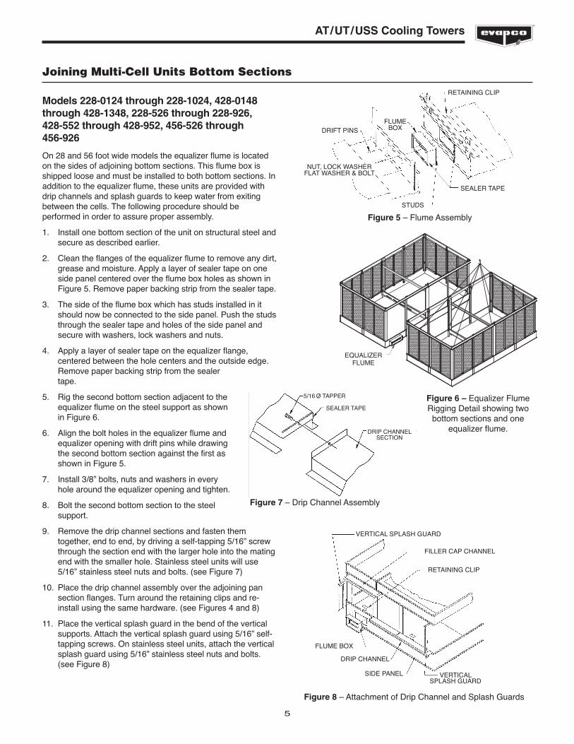
On 28 and 56 foot wide models the equalizer flume is locatedon the sides of adjoining bottom sections. This flume box isshipped loose and must be installed to both bottom sections. Inaddition to the equalizer flume, these units are provided withdrip channels and splash guards to keep water from exitingbetween the cells. The following procedure should beperformed in order to assure proper assembly.
1. Install one bottom section of the unit on structural steel andsecure as described earlier.
2. Clean the flanges of the equalizer flume to remove any dirt,grease and moisture. Apply a layer of sealer tape on oneside panel centered over the flume box holes as shown inFigure 5. Remove paper backing strip from the sealer tape.
3. The side of the flume box which has studs installed in itshould now be connected to the side panel. Push the studsthrough the sealer tape and holes of the side panel andsecure with washers, lock washers and nuts.
4. Apply a layer of sealer tape on the equalizer flange,centered between the hole centers and the outside edge.Remove paper backing strip from the sealertape.
5. Rig the second bottom section adjacent to theequalizer flume on the steel support as shownin Figure 6.
6. Align the bolt holes in the equalizer flume andequalizer opening with drift pins while drawingthe second bottom section against the first asshown in Figure 5.
7. Install 3/8” bolts, nuts and washers in everyhole around the equalizer opening and tighten.
8. Bolt the second bottom section to the steelsupport.
9. Remove the drip channel sections and fasten themtogether, end to end, by driving a self-tapping 5/16” screwthrough the section end with the larger hole into the matingend with the smaller hole. Stainless steel units will use5/16” stainless steel nuts and bolts. (see Figure 7)
10. Place the drip channel assembly over the adjoining pansection flanges. Turn around the retaining clips and re-install using the same hardware. (see Figures 4 and 8)
11. Place the vertical splash guard in the bend of the verticalsupports. Attach the vertical splash guard using 5/16” self-tapping screws. On stainless steel units, attach the verticalsplash guard using 5/16” stainless steel nuts and bolts.(see Figure 8)
5
AT/UT/USS Cooling Towers
DRIFT PINSFLUME
BOX
RETAINING CLIP
SEALER TAPE
STUDS
NUT, LOCK WASHERFLAT WASHER & BOLT
Figure 5 – Flume Assembly
Figure 8 – Attachment of Drip Channel and Splash Guards
VERTICAL SPLASH GUARD
FILLER CAP CHANNEL
RETAINING CLIP
FLUME BOX
DRIP CHANNEL
SIDE PANEL VERTICALSPLASH GUARD
5/16 O TAPPER
DRIP CHANNELSECTION
SEALER TAPE
Figure 7 – Drip Channel Assembly
EQUALIZERFLUME
Figure 6 – Equalizer FlumeRigging Detail showing twobottom sections and one
equalizer flume.
6
AT/UT/USS Cooling Towers
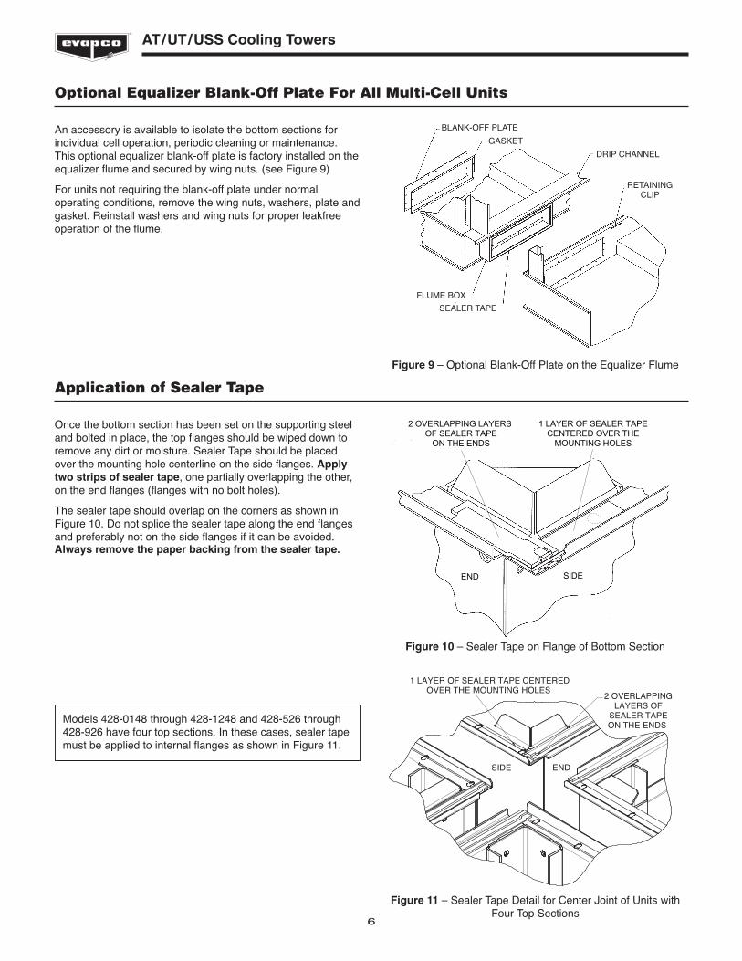
Optional Equalizer Blank-Off Plate For All Multi-Cell Units
An accessory is available to isolate the bottom sections forindividual cell operation, periodic cleaning or maintenance.This optional equalizer blank-off plate is factory installed on theequalizer flume and secured by wing nuts. (see Figure 9)
For units not requiring the blank-off plate under normaloperating conditions, remove the wing nuts, washers, plate andgasket. Reinstall washers and wing nuts for proper leakfreeoperation of the flume.
Figure 9 – Optional Blank-Off Plate on the Equalizer Flume
Application of Sealer Tape
Once the bottom section has been set on the supporting steeland bolted in place, the top flanges should be wiped down toremove any dirt or moisture. Sealer Tape should be placedover the mounting hole centerline on the side flanges. Applytwo strips of sealer tape, one partially overlapping the other,on the end flanges (flanges with no bolt holes).
The sealer tape should overlap on the corners as shown inFigure 10. Do not splice the sealer tape along the end flangesand preferably not on the side flanges if it can be avoided.Always remove the paper backing from the sealer tape.
BLANK-OFF PLATE
GASKET
DRIP CHANNEL
RETAININGCLIP
SEALER TAPE
FLUME BOX
2 OVERLAPPING LAYERS OF SEALER TAPE
ON THE ENDS
END SIDE
1 LAYER OF SEALER TAPECENTERED OVER THE
MOUNTING HOLES
Figure 10 – Sealer Tape on Flange of Bottom Section
Models 428-0148 through 428-1248 and 428-526 through428-926 have four top sections. In these cases, sealer tapemust be applied to internal flanges as shown in Figure 11.
SIDE END
2 OVERLAPPINGLAYERS OF
SEALER TAPEON THE ENDS
1 LAYER OF SEALER TAPE CENTEREDOVER THE MOUNTING HOLES
Figure 11 – Sealer Tape Detail for Center Joint of Units withFour Top Sections

Rigging Top Section
“U” bolts are provided in the four corners of the top section forlifting and final positioning (see Figures 12 and 12b). The hookof the crane must be a minimum dimension “H” above the topsection being lifted to prevent undue strain on the “U” bolts.See Table 2 for the minimum “H” dimension.
7
AT/UT/USS Cooling Towers
Model No. Standard Super LowFan Sound Fan
All 14’ x 24’ Cells 17 Feet 18 Feet
All 14’ x 26’ Cells 22 Feet 27 Feet
Table 2 – Minimum “H” Dimension for Top Sections
Figure 12 – Top Section of 24’ Long Cell
“U” BOLTS
H
Figure 12b – Top Section of 26’ Long Cell
"U" BOLTS
H
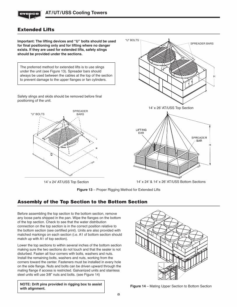
Assembly of the Top Section to the Bottom Section
Before assembling the top section to the bottom section, removeany loose parts shipped in the pan. Wipe the flanges on the bottomof the top section. Check to see that the water distributionconnection on the top section is in the correct position relative tothe bottom section (see certified print). Units are also provided withmatched markings on each section (i.e. A1 of bottom section shouldmatch up with A1 of top section).
Lower the top sections to within several inches of the bottom sectionmaking sure the two sections do not touch and that the sealer is notdisturbed. Fasten all four corners with bolts, washers and nuts.Install the remaining bolts, washers and nuts, working from thecorners toward the center. Fasteners must be installed in every holeon the side flange. Nuts and bolts can be driven upward through themating flange if access is restricted. Galvanized units and stainlesssteel units will use 3/8” nuts and bolts. (see Figure 14)
8
AT/UT/USS Cooling Towers
Extended Lifts
Important: The lifting devices and “U” bolts should be usedfor final positioning only and for lifting where no dangerexists. If they are used for extended lifts, safety slingsshould be provided under the sections.
Safety slings and skids should be removed before finalpositioning of the unit.
The preferred method for extended lifts is to use slingsunder the unit (see Figure 13). Spreader bars shouldalways be used between the cables at the top of the sectionto prevent damage to the upper flanges or fan cylinders.
14’ x 24’ AT/USS Top Section
SPREADERBARS“U” BOLTS
14’ x 26’ AT/USS Top Section
"U" BOLTSSPREADER BARS
H
Figure 13 – Proper Rigging Method for Extended Lifts
14’ x 24’ & 14’ x 26’ AT/USS Bottom Sections
NOTE: Drift pins provided in rigging box to assistwith alignment.
Figure 14 – Mating Upper Section to Bottom Section
H
L
9
AT/UT/USS Cooling Towers
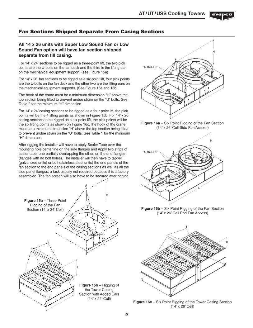
Fan Sections Shipped Separate From Casing Sections
All 14 x 26 units with Super Low Sound Fan or LowSound Fan option will have fan section shippedseparate from fill casing.
For 14’ x 24’ sections to be rigged as a three-point lift, the two pickpoints are the U-bolts on the fan deck and the third is the lifting earon the mechanical equipment support. (see Figure 15a)
For 14’ x 26’ fan sections to be rigged as a six-point lift, four pick pointsare the U-bolts on the fan deck and the other two are the lifting ears onthe mechanical equipment supports. (See Figure 16a and 16b)
The hook of the crane must be a minimum dimension “H” above thetop section being lifted to prevent undue strain on the “U” bolts. SeeTable 2 for the minimum “H” dimension.
For 14’ x 24’ casing sections to be rigged as a four-point lift, the pickpoints will be the 4 lifting points as shown in Figure 15b. For 14’ x 26’casing sections to be rigged as a six-point lift, the pick points will bethe six lifting points as shown on Figure 16c.The hook of the cranemust be a minimum dimension “H” above the top section being liftedto prevent undue strain on the “U” bolts. See Table 1 for the minimum“H” dimension.
After rigging the installer will have to apply Sealer Tape over themounting hole centerline on the side flanges and Apply two strips ofsealer tape, one partially overlapping the other, on the end flanges(flanges with no bolt holes). The installer will then have to tapper(galvanized units) or bolt (stainless steel units) the end panels of thefan section to the end panels of the casing sections as well as all theside panel flanges, a task usually not required because it is a factoryassembled. The fan screen will also have to be secured after rigging.
H
L
Figure 15a – Three PointRigging of the Fan
Section (14’ x 24’ Cell)
"U BOLTS"
H
L
Figure 15b – Rigging ofthe Tower Casing
Section with Added Ears(14’ x 24’ Cell)
Figure 16a – Six Point Rigging of the Fan Section(14’ x 26’ Cell Side Fan Access)
H
L
"U BOLTS"
Figure 16b – Six Point Rigging of the Fan Section(14’ x 26’ Cell End Fan Access)
H
Figure 16c – Six Point Rigging of the Tower Casing Section(14’ x 26’ Cell)
10
AT/UT/USS Cooling Towers
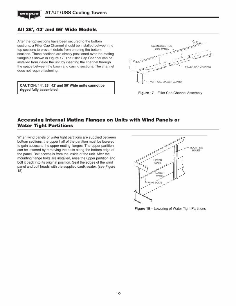
All 28’, 42’ and 56’ Wide Models
After the top sections have been secured to the bottomsections, a Filler Cap Channel should be installed between thetop sections to prevent debris from entering the bottomsections. These sections are simply positioned over the matingflanges as shown in Figure 17. The Filler Cap Channel can beinstalled from inside the unit by inserting the channel throughthe space between the basin and casing sections. The channeldoes not require fastening.
CASING SECTIONSIDE PANEL
FILLER CAP CHANNEL
VERTICAL SPLASH GUARD
Figure 17 – Filler Cap Channel Assembly
CAUTION: 14’, 28’, 42’ and 56’ Wide units cannot berigged fully assembled.
Accessing Internal Mating Flanges on Units with Wind Panels or Water Tight Partitions
When wind panels or water tight partitions are supplied betweenbottom sections, the upper half of the partition must be loweredto gain access to the upper mating flanges. The upper partitioncan be lowered by removing the bolts along the bottom edge ofthe panel. Bolt access is from the inside of the unit. After themounting flange bolts are installed, raise the upper partition andbolt it back into its original position. Seal the edges of the windpanel and bolt heads with the supplied caulk sealer. (see Figure18)
MOUNTINGHOLES
UPPERPANEL
LOWERPANEL
WING BOLTS
Figure 18 – Lowering of Water Tight Partitions
11
AT/UT/USS Cooling Towers
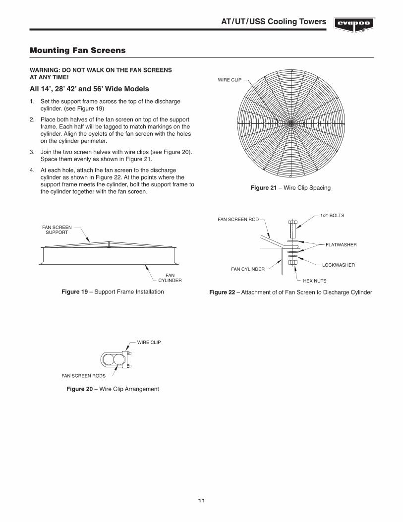
Mounting Fan Screens
WARNING: DO NOT WALK ON THE FAN SCREENS AT ANY TIME!
All 14’, 28’ 42’ and 56’ Wide Models
1. Set the support frame across the top of the dischargecylinder. (see Figure 19)
2. Place both halves of the fan screen on top of the supportframe. Each half will be tagged to match markings on thecylinder. Align the eyelets of the fan screen with the holeson the cylinder perimeter.
3. Join the two screen halves with wire clips (see Figure 20).Space them evenly as shown in Figure 21.
4. At each hole, attach the fan screen to the dischargecylinder as shown in Figure 22. At the points where thesupport frame meets the cylinder, bolt the support frame tothe cylinder together with the fan screen.
FAN SCREENSUPPORT
FANCYLINDER
Figure 20 – Wire Clip Arrangement
WIRE CLIP
FAN SCREEN RODS
WIRE CLIP
FAN SCREEN ROD1/2” BOLTS
FLATWASHER
LOCKWASHERFAN CYLINDER
HEX NUTS
Figure 19 – Support Frame Installation Figure 22 – Attachment of of Fan Screen to Discharge Cylinder
Figure 21 – Wire Clip Spacing
12
AT/UT/USS Cooling Towers
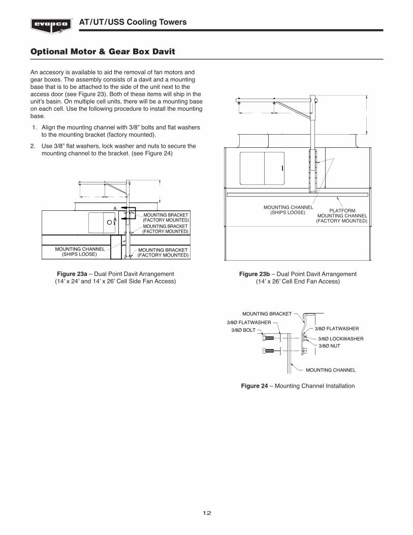
Optional Motor & Gear Box Davit
An accesory is available to aid the removal of fan motors andgear boxes. The assembly consists of a davit and a mountingbase that is to be attached to the side of the unit next to theaccess door (see Figure 23). Both of these items will ship in theunit’s basin. On multiple cell units, there will be a mounting baseon each cell. Use the following procedure to install the mountingbase.
1. Align the mounting channel with 3/8” bolts and flat washersto the mounting bracket (factory mounted).
2. Use 3/8” flat washers, lock washer and nuts to secure themounting channel to the bracket. (see Figure 24)
MOUNTING BRACKET
MOUNTING CHANNEL
3/8Ø BOLT
3/8Ø FLATWASHER3/8Ø FLATWASHER
3/8Ø NUT
3/8Ø LOCKWASHER
Figure 24 – Mounting Channel Installation
MOUNTING BRACKET(FACTORY MOUNTED)
MOUNTING BRACKET(FACTORY MOUNTED)
MOUNTING BRACKET(FACTORY MOUNTED)
MOUNTING CHANNEL(SHIPS LOOSE)
A
A
Figure 23a – Dual Point Davit Arrangement(14’ x 24’ and 14’ x 26’ Cell Side Fan Access)
PLATFORMMOUNTING CHANNEL
(FACTORY MOUNTED)
MOUNTING CHANNEL(SHIPS LOOSE)
Figure 23b – Dual Point Davit Arrangement(14’ x 26’ Cell End Fan Access)

13
AT/UT/USS Cooling Towers
Assembly of Sloped Ladders
When sloped ladders are supplied with a unit, they are shippedin the basin of the unit. One sloped ladder will be provided foreach cell. Assembly is identical for each cell. Sloped ladders areattached at a minimum of three points. Taller units will beattached at four points. At each point of attachment, the ladderwill be fitted with a ladder bracket assembly. The ladder bracketassembly looks like a metal box and is shown in detail(component #4) in Figure 25 below. The upper two assemblybrackets will be rigidly mounted to the ladder and are notadjustable. These two bracket define the slope of the ladder.The lower brackets are adjustable.
To install the ladder assembly, follow the steps outlined belowwhich refer to Figure 26:
1. Remove the ladder bracket mounting bolts (1) from theladder mounting channels (2) on pan and casing sections.
2. Loosen, but do not remove, the ladder bracket andassembly bolts (3).
3. Slide the ladder bracket assembly (4) over the laddermounting channels (2) located on the pan and casingsections. Do not remove the ladder bracket assembly (4)from the ladder.
4. Align the bolt holes and reinstall the ladder bracketmounting bolts (1) through the ladder bracket assembly andthe ladder mounting channels (2).
5. Tighten all bolts.
6. Tighten the adjusting screw (5) in the adjustable mountingbracket where applicable.
LADDER SHIPS LOOSE FORFIELD MOUNTING (BY OTHERS)
26
ADJUSTING SCREW(5)
(WHEN APPLICABLE)
LADDER MOUNTINGCHANNEL (2)
LADDER BRACKETMOUNTING BOLTS
(1)
LADDER BRACKETASSEMBLY
(4)
LADDER BRACKETASSEMBLY BOLTS
(3)
PAN OR CASINGPANEL
Figure 25 – Detail of Ladder, Ladder Bracket Assembly andMounting Channel
Figure 26 – End View of Ladder Assembly
ACCESSDOOR
Figure 26b – Side View of Ladder Assembly
NOTE: Upper section of unit must be properly orientedwith respect to lower section. All mounting bracketsmust be on same side of unit. Refer to certified print forproper orientation.
Figure 26c – 14 x 26 Side View
14
AT/UT/USS Cooling Towers
TITL
E
CUT
N.C
.
DRA
WN
WARA
G
.O
N .V ER.
ON TRAP
STAI
NLE
SS S
TEEL
OPT
ION
PART
NO
.RE
V. N
O.
REVISIONS
PART
NEX
T
SIZE
INFO
.
BY ASSE
MBL
Y:
MAT
'L
NO
.M
AT'L
RAW
NO
TE:
EVAP
CO, I
NC.
DAT
E
CH'K
DBY
CON
FID
ENTI
ALTh
is d
ocum
ent
is t
he p
rope
rty
of E
vapc
o, I
nc. I
t sh
ould
not
be c
opie
d or
dis
clos
ed w
ithou
t pr
ior
writ
ten
auth
oriz
atio
n.
SCAL
E1.
ALL
1/4
Ø H
OLE
S SH
OU
LD B
E 11
/32Ø
2. U
SE S
TAIN
LESS
STE
EL N
.C. S
ET-U
P SH
EET
F F
DET
AIL
E
DET
AIL
B
DET
AIL
AD
ETAI
L C
SHIP
TH
IS D
RA
WIN
G W
ITH
UN
IT
CON
NEC
TIO
NPL
ATE
CON
NEC
TIO
NPL
ATE
SECU
RE D
ECK
SUPP
ORT
TO C
ON
NEC
TIO
NPL
ATES
WTH
5/8
" G
RAD
E 5
HAR
DW
ARE
DEC
K SU
PPO
RTD
ECK
SUPP
ORT
SECU
RE D
IAG
ON
ALSU
PPO
RT T
O D
ECK
SUPP
ORT
USI
NG
5/8
"G
RAD
E 5
HAR
DW
ARE
DIA
GO
NAL
SU
PPO
RT
DIA
GO
NAL
SUPP
ORT
SECU
RE D
IAG
ON
ALSU
PPO
RT T
O C
ON
NEC
TIO
NPL
ATE
USI
NG
5/8
"G
RAD
E 5
HAR
DW
ARE
SECU
RE R
AILI
NG
FITT
ING
TO
FRO
NT
TOEP
LATE
USI
NG
3/8
" G
RAD
E 5
HAR
DW
ARE
FRO
NT
TOEP
LATE
RAIL
ING
FIT
TIN
G
SECU
RE L
ADD
ER B
RACK
ETTO
BAS
E O
N U
NIT
WIT
H3/
8" G
RAD
E 5
HAR
DW
ARE
LAD
DER
BRA
CKET
BASE
DET
AIL
DN
OTE
S:1.
PLA
TFO
RM G
RATI
NG
NO
T SH
OW
N F
OR
CLAR
ITY
DET
AIL
F1/
2" N
UT
HAN
DRA
IL F
ITTI
NG
1
EB
AC
D
FIEL
D A
SSY
PLTF
GEN
ERAL
ARR
03/2
8/01
N.T
.S.
JLC
093-
0434
2GA
3
093-
0434
2GA
3
ADDED DETAIL F.JPM 7/10/02
1
MADE DWG A SIZE.TLS 7/02/07
2
ADDED NOTE FANDECK ATTACHMENT.TLS 8/17/07
3
FAN
DEC
KAT
TACH
MEN
TIF
APP
LICA
BLE
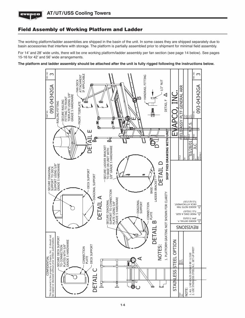
Field Assembly of Working Platform and Ladder
The working platform/ladder assemblies are shipped in the basin of the unit. In some cases they are shipped separately due tobasin accessories that interfere with storage. The platform is partially assembled prior to shipment for minimal field assembly.
For 14’ and 28’ wide units, there will be one working platform/ladder assembly per fan section (see page 14 below). See pages 15-16 for 42’ and 56’ wide arrangements.
The platform and ladder assembly should be attached after the unit is fully rigged following the instructions below.

15
AT/UT/USS Cooling Towers
TITL
E
CUT
N.C
.
DRA
WN
W ARA
G
.O
N .VER.
ON TRAP
STAI
NLE
SS S
TEEL
OPT
ION
PART
NO
.RE
V. N
O.
REVISIONS
PART
NEX
T
SIZE
INFO
.
BY ASSE
MBL
Y:
MAT
'L
NO
.M
AT'L
RAW
NO
TE:
EVAP
CO, I
NC.
DAT
E
CH'K
DBY
CON
FID
ENTI
ALTh
is d
ocum
ent
is t
he p
rope
rty
of E
vapc
o, I
nc. I
t sh
ould
not
be c
opie
d or
dis
clos
ed w
ithou
t pr
ior
writ
ten
auth
oriz
atio
n.
SCAL
E1.
ALL
1/4
Ø H
OLE
S SH
OU
LD B
E 11
/32Ø
2. U
SE S
TAIN
LESS
STE
EL N
.C. S
ET-U
P SH
EET
NO
TE:
1.)
PLAT
FORM
GRA
TIN
G I
S N
OT
SHO
WN
FO
R CL
ARIT
Y.
FIEL
D A
SSY
PLTF
GEN
ERAL
ARR
11/2
2/11
N.T
.S.
AWR
093-
3074
8GA
-
093-
3074
8GA
-
A
DET
AIL
A
BDET
AIL
B
SECU
RE D
ECK
SUPP
ORT
TO
CO
NN
ECTI
ON
PLA
TES
WIT
H 5
/8"
GR
ADE
5 H
ARD
WAR
E
CO
NN
ECTI
ON
PLA
TE
DEC
K SU
PPO
RT
DEC
K SU
PPO
RT
SECU
RE D
IAG
ON
AL S
UPP
ORT
TO D
ECK
SUPP
ORT
USI
NG
5/8
" G
RAD
E 5
HAR
DW
ARE
DIA
GO
NAL
SU
PPO
RT
D
DET
AIL
D
E
DET
AIL
E
CD
ETAI
L C
SHIP
TH
IS D
RA
WIN
G W
ITH
UN
IT
SECU
RE L
ADD
ER B
RACK
ETTO
BAS
E O
N U
NIT
WIT
H 3
/8"
GR
ADE
5 H
ARD
WAR
E
LAD
DER
BRA
CKET
BASE
SECU
RE D
IAG
ON
AL S
UPP
ORT
TO
CON
NEC
TIO
N P
LATE
USI
NG
5/8
"G
RAD
E 5
HAR
DW
ARE
DIA
GO
NAL
SU
PPO
RT
CON
NEC
TIO
N P
LATE
SECU
RE R
AILI
NG
FIT
TIN
G T
OFR
ON
T TO
EPLA
TE U
SIN
G 3
/8"
GR
ADE
5 H
ARD
WAR
E
RAIL
ING
FIT
TIN
G
TOEP
LATE
VIEW
F1/
2" N
UT
HAN
DR
AIL
FITT
ING
F
REF.
TO
093
-307
49G
A
WAS
HER
16
AT/UT/USS Cooling Towers
TITL
E
CUT
N.C
.
DRA
WN
W ARA
G
.O
N .VER.
ON TRAP
STAI
NLE
SS S
TEEL
OPT
ION
PART
NO
.RE
V. N
O.
REVISIONS
PART
NEX
T
SIZE
INFO
.
BY ASSE
MBL
Y:
MAT
'L
NO
.M
AT'L
RAW
NO
TE:
EVAP
CO, I
NC.
DAT
E
CH'K
DBY
CON
FID
ENTI
ALTh
is d
ocum
ent
is t
he p
rope
rty
of E
vapc
o, I
nc. I
t sh
ould
not
be c
opie
d or
dis
clos
ed w
ithou
t pr
ior
writ
ten
auth
oriz
atio
n.
SCAL
E1.
ALL
1/4
Ø H
OLE
S SH
OU
LD B
E 11
/32Ø
2. U
SE S
TAIN
LESS
STE
EL N
.C. S
ET-U
P SH
EET
NO
TE:
1.)
PLAT
FORM
GRA
TIN
G I
S N
OT
SHO
WN
FO
R CL
ARIT
Y.2.
) RE
PEAT
TH
IS P
ROCE
SS W
ITH
ALL
SPA
CER
PLAT
FORM
SEC
TIO
NS
SH
IP T
HIS
DR
AW
ING
WIT
H U
NIT
BACK
SPA
CER
TOEP
LATE
DIA
GO
NAL
SU
PPO
RT
DEC
K SU
PPO
RTSP
ACER
SEC
TIO
N
SECU
RE D
IAG
ON
AL S
UPP
ORT
TO
BO
TH D
ECK
SUPP
ORT
SU
SIN
G 5
/8"
GRA
DE
5 H
ARD
WAR
E
SAFE
TY C
HAN
NEL
:RE
STS
ON
TO
P O
F BA
CK S
PACE
R TO
EPLA
TEG
ALVA
NIZ
ED U
NIT
S AT
TACH
USI
NG
5/1
6" S
ELF-
TAPP
ING
SCR
EWS
STAI
NLE
SS S
TEEL
UN
ITS
ATTA
CH U
SIN
G 5
/16"
STA
INLE
SS S
TEEL
NU
TS A
ND
BO
LTS
B
DET
AIL
B
FIEL
D A
SSY
SPAC
ER P
LTF
GEN
ERAL
ARR
11/2
3/11
N.T
.S.
AWR
093-
3074
9GA
-
093-
3074
9GA
-
SLID
E RA
ILIN
G C
OU
PLIN
GTO
EN
GAG
E BO
TH R
AILS
AND
TIG
HTE
N
17
AT/UT/USS Cooling Towers
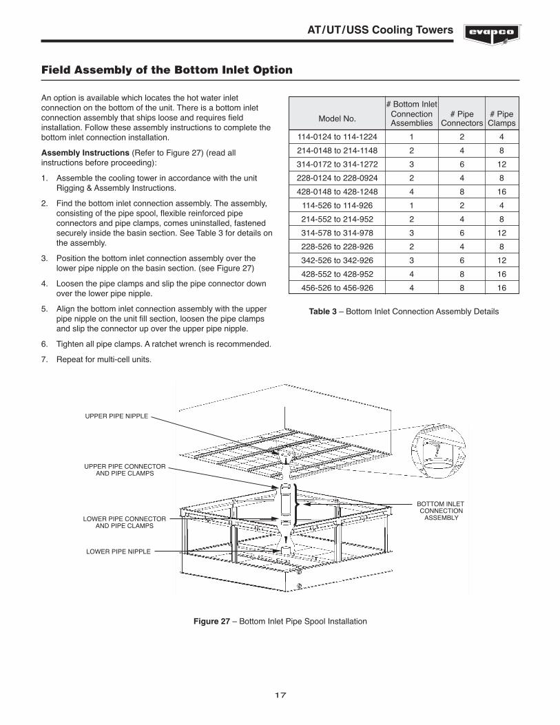
Field Assembly of the Bottom Inlet Option
An option is available which locates the hot water inletconnection on the bottom of the unit. There is a bottom inletconnection assembly that ships loose and requires fieldinstallation. Follow these assembly instructions to complete thebottom inlet connection installation.
Assembly Instructions (Refer to Figure 27) (read allinstructions before proceeding):
1. Assemble the cooling tower in accordance with the unitRigging & Assembly Instructions.
2. Find the bottom inlet connection assembly. The assembly,consisting of the pipe spool, flexible reinforced pipeconnectors and pipe clamps, comes uninstalled, fastenedsecurely inside the basin section. See Table 3 for details onthe assembly.
3. Position the bottom inlet connection assembly over thelower pipe nipple on the basin section. (see Figure 27)
4. Loosen the pipe clamps and slip the pipe connector downover the lower pipe nipple.
5. Align the bottom inlet connection assembly with the upperpipe nipple on the unit fill section, loosen the pipe clampsand slip the connector up over the upper pipe nipple.
6. Tighten all pipe clamps. A ratchet wrench is recommended.
7. Repeat for multi-cell units.
UPPER PIPE NIPPLE
UPPER PIPE CONNECTORAND PIPE CLAMPS
BOTTOM INLET CONNECTION
ASSEMBLYLOWER PIPE CONNECTORAND PIPE CLAMPS
LOWER PIPE NIPPLE
Figure 27 – Bottom Inlet Pipe Spool Installation
# Bottom Inlet
Model No. Connection # Pipe # PipeAssemblies Connectors Clamps
114-0124 to 114-1224 1 2 4
214-0148 to 214-1148 2 4 8
314-0172 to 314-1272 3 6 12
228-0124 to 228-0924 2 4 8
428-0148 to 428-1248 4 8 16
114-526 to 114-926 1 2 4
214-552 to 214-952 2 4 8
314-578 to 314-978 3 6 12
228-526 to 228-926 2 4 8
342-526 to 342-926 3 6 12
428-552 to 428-952 4 8 16
456-526 to 456-926 4 8 16
Table 3 – Bottom Inlet Connection Assembly Details
18
AT/UT/USS Cooling Towers
General Information - Start-up & Maintenance Start-up Details Shipping Chocks and Debris
Remove any chocks that have been placed inside the unit for shipping purposes. Be sure to remove the chocks from between thefan and fan guard. Clean all debris from the pan prior to start-up. Close and secure all access doors.
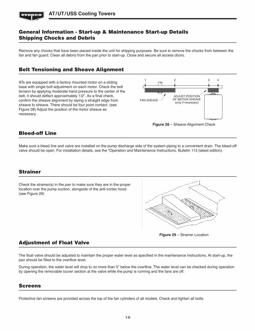
Belt Tensioning and Sheave Alignment
ATs are equipped with a factory mounted motor on a slidingbase with single bolt adjustment on each motor. Check the belttension by applying moderate hand pressure to the center of thebelt, it should deflect approximately 1/2”. As a final check,confirm the sheave alignment by laying a straight edge fromsheave to sheave. There should be four point contact. (seeFigure 28) Adjust the position of the motor sheave asnecessary.
FAN SHEAVEADJUST POSITION
OF MOTOR SHEAVE(only if necessary)
1 2 3 4
Figure 28 – Sheave Alignment Check
Bleed-off Line
Make sure a bleed line and valve are installed on the pump discharge side of the system piping to a convenient drain. The bleed-offvalve should be open. For installation details, see the “Operation and Maintenance Instructions, Bulletin 113 (latest edition).
Strainer
Check the strainer(s) in the pan to make sure they are in the properlocation over the pump suction, alongside of the anti-vortex hood.(see Figure 29)
Figure 29 – Strainer Location
Adjustment of Float Valve
The float valve should be adjusted to maintain the proper water level as specified in the maintenance instructions. At start-up, thepan should be filled to the overflow level.
During operation, the water level will drop to no more than 5” below the overflow. The water level can be checked during operationby opening the removable louver section at the valve while the pump is running and the fans are off.
Screens
Protective fan screens are provided across the top of the fan cylinders of all models. Check and tighten all bolts.
19
AT/UT/USS Cooling Towers
Starting Sequence
Before starting the unit, check that all access openings, safety screens and covers are in place. Start the unit as outlined below:
1. Fill the pan to the overflow level.
2. Start the water pumps (by others). Check the water flow tothe unit by checking the spray water pressure at the waterinlet. It should be the same as the pressure indicated on thecertified drawing.
3. Start the fans. Check the fans for proper rotation.Directional arrows are on the side of the fan cylinder.
NOTE: Do not operate the fans while the pump is off.Damage to the PVC fill can result during dryoperation. Always start the water pumps first.
Maintenance
Once the installation is complete and the unit is turned on, it is important that it be properly maintained. Maintenance is not difficultor time-consuming but must be done regularly to assure full performance of the unit. Refer to the maintenance instructionsenclosed with the unit for proper maintenance procedures.
Freeze Protection
Proper freeze protection must be provided if the unit is located in a cold climate. Refer to maintenance instructions as well asproduct bulletins for further information.
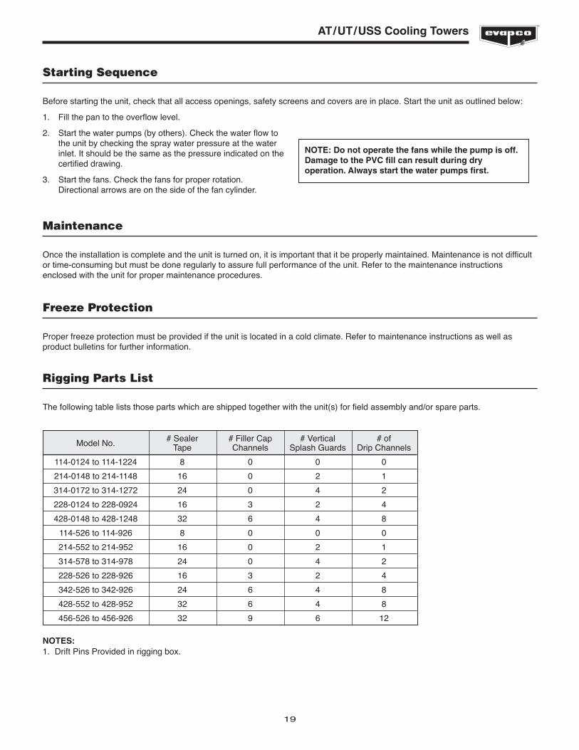
Rigging Parts List
The following table lists those parts which are shipped together with the unit(s) for field assembly and/or spare parts.
Model No. # Sealer # Filler Cap # Vertical # ofTape Channels Splash Guards Drip Channels
114-0124 to 114-1224 8 0 0 0
214-0148 to 214-1148 16 0 2 1
314-0172 to 314-1272 24 0 4 2
228-0124 to 228-0924 16 3 2 4
428-0148 to 428-1248 32 6 4 8
114-526 to 114-926 8 0 0 0
214-552 to 214-952 16 0 2 1
314-578 to 314-978 24 0 4 2
228-526 to 228-926 16 3 2 4
342-526 to 342-926 24 6 4 8
428-552 to 428-952 32 6 4 8
456-526 to 456-926 32 9 6 12
NOTES:1. Drift Pins Provided in rigging box.

EVAPCO, Inc. • P.O. Box 1300 • Westminster, MD 21158 USAPHONE: 410-756-2600 • FAX: 410-756-6450 • E-MAIL: [email protected]
©2012 EVAPCO, Inc.Printed on recycled paper
using soy-based ink