riello burner handbook
TRANSCRIPT

7/25/2019 Riello Burner Handbook
http://slidepdf.com/reader/full/riello-burner-handbook 1/169

7/25/2019 Riello Burner Handbook
http://slidepdf.com/reader/full/riello-burner-handbook 2/169
FORCED DRAUGHT
BURNER
HANDBOOK
S e p t e m b e r 2 0 0 1
First Edition
RIELLO S.p.A.Legnago - Italy

7/25/2019 Riello Burner Handbook
http://slidepdf.com/reader/full/riello-burner-handbook 3/169
© 2001 RIELLO S.p.A. - LEGNAGO
Rights for translation, electronic memorization, reproduction and total or partial adaptment
with every mean (included photostatic copies or microfilms) are reserved.
First edition: September 2001

7/25/2019 Riello Burner Handbook
http://slidepdf.com/reader/full/riello-burner-handbook 4/169
1 FUNDAMENTAL COMBUSTION PRINCIPLES 13
1.1. Basic reactions 13
1.2. The combustion supporter 13
1.3. The combustion supporter 14
1.3.1. Gaseous fuels and their combustion 16
1.3.2. Liquid fuels and their combustion 21
1.4. Pollutant combustion emissions 21
1.4.1. Sulphur oxides 22
1.4.2. Nitric oxides 22
1.4.2.1. Reduction of the NOx in gaseous fuel combustion 23
1.4.2.2. Reduction of the NOx in liquid fuel combustion 25
1.4.3. Carbon monoxide (CO) 25
1.4.4. Total suspended particles 26
1.4.5. Comments on the emission of CO2 27
1.5. Combustion control 27
1.5.1. Combustion efficiency 29
1.5.2. Measurement units for combustion emissions 29
2 THE FORCED DRAUGHT BURNER 31
2.1 Foreword 31
2.2 The firing range of a burner 32
2.3 Typical system layout diagrams 35
2.3.1 System engineering diagrams for fired burners 36
2.3.2 System engineering diagrams for burners using
low viscosity (< 6 cSt) liquid fuels - diesel oil / kerosene 36
2.3.3 System engineering diagrams for burners using
high viscosity (> 6 cSt) liquid fuels 372.3.4 Diagrams for the calibration of single-stage burners 38
2.3.5 Diagrams for the calibration of multi-stage burners 39
2.3.6 Diagrams for the calibration of modulating burners 39
2.3.7 Diagram of burner with measurement and regulation
of the percentage of O2 in the flue gases 40
2.3.8 Diagram of burner with pre-heating of the combustion supporter air 40
2.3.9 Diagram of burner with inverter controlled motors 41
2.3.10 Layout of the Burner Management -System 41
2.4 The Combustion head 42
2.4.1 Pressure drop air side 43
2.4.2 Pressure drop fuel side 43
2.5 The Fan 44
2.5.1 Regulating combustion air 46
SUMMARY
7/25/2019 Riello Burner Handbook
http://slidepdf.com/reader/full/riello-burner-handbook 5/169
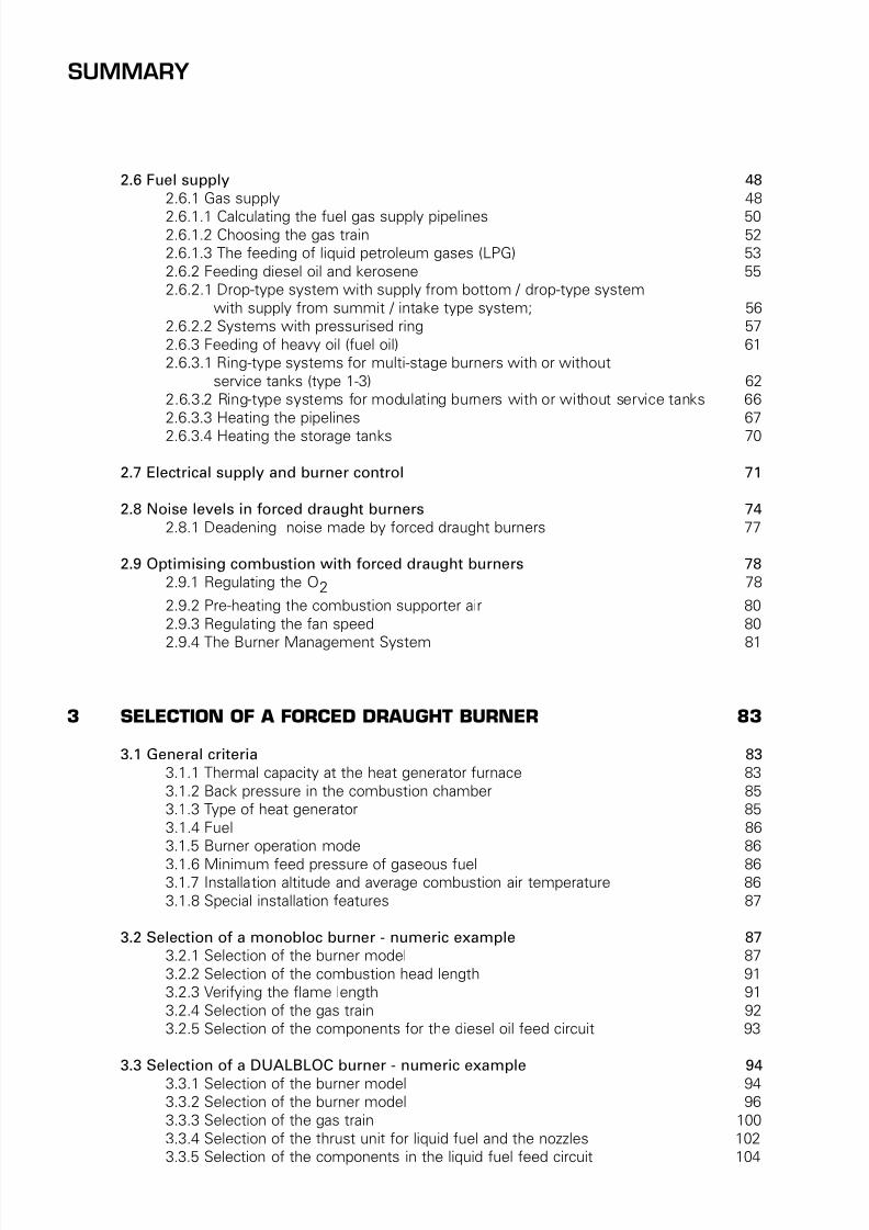
2.6 Fuel supply 48
2.6.1 Gas supply 48
2.6.1.1 Calculating the fuel gas supply pipelines 502.6.1.2 Choosing the gas train 52
2.6.1.3 The feeding of liquid petroleum gases (LPG) 53
2.6.2 Feeding diesel oil and kerosene 55
2.6.2.1 Drop-type system with supply from bottom / drop-type system
with supply from summit / intake type system; 56
2.6.2.2 Systems with pressurised ring 57
2.6.3 Feeding of heavy oil (fuel oil) 61
2.6.3.1 Ring-type systems for multi-stage burners with or without
service tanks (type 1-3) 62
2.6.3.2 Ring-type systems for modulating burners with or without service tanks 66
2.6.3.3 Heating the pipelines 67
2.6.3.4 Heating the storage tanks 70
2.7 Electrical supply and burner control 71
2.8 Noise levels in forced draught burners 74
2.8.1 Deadening noise made by forced draught burners 77
2.9 Optimising combustion with forced draught burners 78
2.9.1 Regulating the O2 78
2.9.2 Pre-heating the combustion supporter air 80
2.9.3 Regulating the fan speed 80
2.9.4 The Burner Management System 81
3 SELECTION OF A FORCED DRAUGHT BURNER 83
3.1 General criteria 83
3.1.1 Thermal capacity at the heat generator furnace 83
3.1.2 Back pressure in the combustion chamber 85
3.1.3 Type of heat generator 85
3.1.4 Fuel 86
3.1.5 Burner operation mode 86
3.1.6 Minimum feed pressure of gaseous fuel 863.1.7 Installation altitude and average combustion air temperature 86
3.1.8 Special installation features 87
3.2 Selection of a monobloc burner - numeric example 87
3.2.1 Selection of the burner model 87
3.2.2 Selection of the combustion head length 91
3.2.3 Verifying the flame length 91
3.2.4 Selection of the gas train 92
3.2.5 Selection of the components for the diesel oil feed circuit 93
3.3 Selection of a DUALBLOC burner - numeric example 94
3.3.1 Selection of the burner model 943.3.2 Selection of the burner model 96
3.3.3 Selection of the gas train 100
3.3.4 Selection of the thrust unit for liquid fuel and the nozzles 102
3.3.5 Selection of the components in the liquid fuel feed circuit 104
SUMMARY

7/25/2019 Riello Burner Handbook
http://slidepdf.com/reader/full/riello-burner-handbook 6/169
3.3.5.1 Transfer pump between the storage tank and the service tank 105
3.3.5.2 Service tank 105
3.3.5.3 Pump in the main ring 1053.3.5.4 Dimensioning the main ring pipelines 106
3.3.6 Selection of the electrical control panel 107
4 MEASURING COMBUSTION EFFICIENCY 109
4.1 Instruments 109
4.2 Preliminary operations 109
4.2.1 Systems fired by liquid fuel 1094.2.2 Systems fired by gaseous fuel 109
4.3 Measurement conditions and operating methods 110
4.4 Calculating the combustion efficiency 111
4.4.1 Example for calculating combustion efficiency 111
5 READY-USE TABLES AND DIAGRAMS 115
5.1 Measuring units and conversion factors 115
5.2 Tables and diagrams about fuel viscosity 129
5.3 Tables and diagrams for circuits dimensioning 134
5.4 Tables and diagrams about combustion 156
SUMMARY

7/25/2019 Riello Burner Handbook
http://slidepdf.com/reader/full/riello-burner-handbook 7/169
SUMMARY OF DIAGRAMS
1 FUNDAMENTAL COMBUSTION PRINCIPLES 13
Diagram 1 - Elementary representation of a flame 13Diagram 2 - Temperature and altitude influence on effective air delivery 14
Diagram 3 - Example of a viscosimeter 16
Diagram 4 - Formation process of acid rain 22
Diagram 5 - Type of NOx in certain fuels 23
Diagram 6 - Functional layout of combustion process for a gas burner - Blue flame type 24
Diagram 7 - Monobloc burner (light oil - Low NOx) of BGK series 25
Diagram 8 - Effects of carbon monoxide 25
Diagram 9 - Penetration of the particles in the respiratory system 26
Diagram 10 - Combustion triangle for methane gas 28
2 THE FORCED DRAUGHT BURNER 31
Diagram 11 - Gas fired monobloc burner 31
Diagram 12 - Burners operating chances: a) one-stage, b) two-stage, c) progressive
two-stage, d) modulating 32
Diagram 13 - Layout of two monobloc (RL and RS series) burners and dual bloc
(TI) burner 33
Diagram 14 - Firing ranges of Riello RLS series dual fuel burners 34
Diagram 15 - Test combustion chamber for burners 34
Diagram 16 - Firing range of Riello RLS100- two stage gas/light oil burner 35
Diagram 17 - Firing range for Riello TI Series Burner combustion heads 35Diagram 18 - Gas supply - low pressure circuit 36
Diagram 19 - Gas supply - high pressure circuit 36
Diagram 20 - A=Drop-type plant with fedding from top; B=air intake system 36
Diagram 21 - Drop-type plant with feeding from bottom 36
Diagram 22 - System with ring under pressure 37
Diagram 23 - Ring-type system for multi-stage and modulating burners with service tank 37
Diagram 24 - Ring-type system for multi-stage and modulating burners without service tank 38
Diagram 25 - Layout of regulation components for a single-stage burner 38
Diagram 26 - Layout of regulation components for a two-stage burner 39
Diagram 27 - Layout of regulation components for a modulating burner 39
Diagram 28 - Layout of O2 regulation system 40
Diagram 29 - Layout of a system with pre-heating of comburent air 40Diagram 30 - Layout of the fan speed rotation regulation with inverter 41
Diagram 31 - Layout of integrated management for supervising a combustion system 41
Diagram 32 - Nozzles: full cone and empty cone distribution; definition of spray angle 42
Diagram 33 - Drawing of composition of combustion head for gas/light oil Riello
RLS 100 burner 42
Diagram 34 - Pressure drop air side in combustion head - dualbloc TI 10 burner 43
Diagram 35 - Pressure drop gas side in combustion head - dualbloc TI 10 burner 43
Diagram 36 - Feed pressure of liquid fuel 44
Diagram 37 - Fan of a dualbloc burner 44
Diagram 38 - Output absorbed from different types of fan varying delivery 44
Diagram 39 - Typical performance graphs of a centrifugal fan 45
Diagram 40 - Fan performance graphs on varying motor speed rotation 45Diagram 41 - Performance graph of fan and resistant circuit with working point 45
Diagram 42 - Moody's abacus 47
Diagram 43 - Adimensional loss factors for air pipelines 47
Diagram 44 - Change of delivery by varying pressure drops of the circuit 48

7/25/2019 Riello Burner Handbook
http://slidepdf.com/reader/full/riello-burner-handbook 8/169
Diagram 45 - Example of delivery changing by motor speed variation 48
Diagram 46 - Functional layout of the gas train 49
Diagram 47 - Gas filter 49Diagram 48 - Pressure Regulator 49
Diagram 49 - Shut-off and safety valves 50
Diagram 50 - Gas pressure switch 50
Diagram 51 - Seal control system 50
Diagram 52 - Connection adaptor 50
Diagram 53 - Absolute viscosity of certain gases 51
Diagram 54 - LPG tank 53
Diagram 55 - Graph for the detrmination of the gas train 53
Diagram 56 - Shut-off solenoid valve on output circuit - close postition 55
Diagram 57 - Gear pump for liquid fule monobloc burner 55
Diagram 58 - Light oil burner feeding 56
Diagram 59 - Moody's abacus 60Diagram 60 - Pressure regulating valve 60
Diagram 61 - Heavy oil preheating unit 61
Diagram 62 - Pumps for fuel oil 62
Diagram 63 - Service tank 63
Diagram 64 - Ring pressure - advised values 67
Diagram 65 - Self-regulating heating band 69
Diagram 66 - Turns' step for heating bands 69
Diagram 67 - Electrical layout of a monobloc burner with single-phase
electrical power supply 71
Diagram 68 - Electrical layout of a monobloc burner with three phase power supply 71
Diagram 69 - Firing sequence of a methane gas burner 72
Diagram 70 - Diagram of the main components required for combustion
control and regulation 72
Diagram 71 - Programming of the regulation temperatures for a two-stage burner 73
Diagram 72 - Electrical layout of a modulating burner with control devices 74
Diagram 73 - Isophonic curves 75
Diagram 74 - Weighted curves 76
Diagram 75 - Blimp for air blown burners 78
Diagram 76 - Reference values of the oxygen content in flue gases for a gas burner 79
Diagram 77 - Loss of the flue gases for different % of O2 80
Diagram 78 - Diagram for the evaluation of the energy saving by means of the inverter 81
Diagram 79 - Conceptual representation of a Burner Management System 82
Diagram 80 - Electrical power absorption with O2 regulation and inverter 82
3 SELECTION OF A FORCED DRAUGHT BURNER 83
Diagram 81 - Combustion chamber backpressure in relation to thermal output 85
Diagram 82 - Reverse flame boiler 85
Diagram 83 - Serpentine boiler 85
Diagram 84 - Fixing of the blast tube to the boiler port 86
Diagram 85 - Dual fuel (light oil-gas) burner of RLS series 88
Diagram 86 - Combustion head 91
Diagram 87 - Hot water boiler constructive layout 91Diagram 88 - Lenght and diameter of the flame in relation to burner output 92
Diagram 89 - Diagram for selection of gas trains 93
Diagram 90 - Layout of a light oil feeding circuit 94
Diagram 91 - Dualbloc burner of TI series 94
SUMMARY OF DIAGRAMS

7/25/2019 Riello Burner Handbook
http://slidepdf.com/reader/full/riello-burner-handbook 9/169
Diagram 92 - Firing ranges for Riello TI Series of burner combustion heads 97
Diagram 93 - Combustion head pressure drops for TI series - air side 98
Diagram 94 - Pressure drops in circular pipelines 99Diagram 95 - Performence graphs of GBJ fan series 100
Diagram 96 - Combustion head and butterfly valve pressure drops for TI series - gas side 101
Diagram 97 - Pressure drops in DMV safety valves 101
Diagram 98 - Nozzles delivery for modulating burners 103
Diagram 99 - Layout of a heavy oil feeding circuit 104
4 MEASURING COMBUSTION EFFICIENCY 109
Diagram 100 - Example of analyzer for measuring combustion efficiency 109
Diagram 101 - Gas flow characteristics measuring points 110
SUMMARY OF DIAGRAMS

7/25/2019 Riello Burner Handbook
http://slidepdf.com/reader/full/riello-burner-handbook 10/169
1 FUNDAMENTAL COMBUSTION PRINCIPLES 13
Table 1 - Principal fuels classification 14Table 2 - Characteistics of gaseous fuels 18
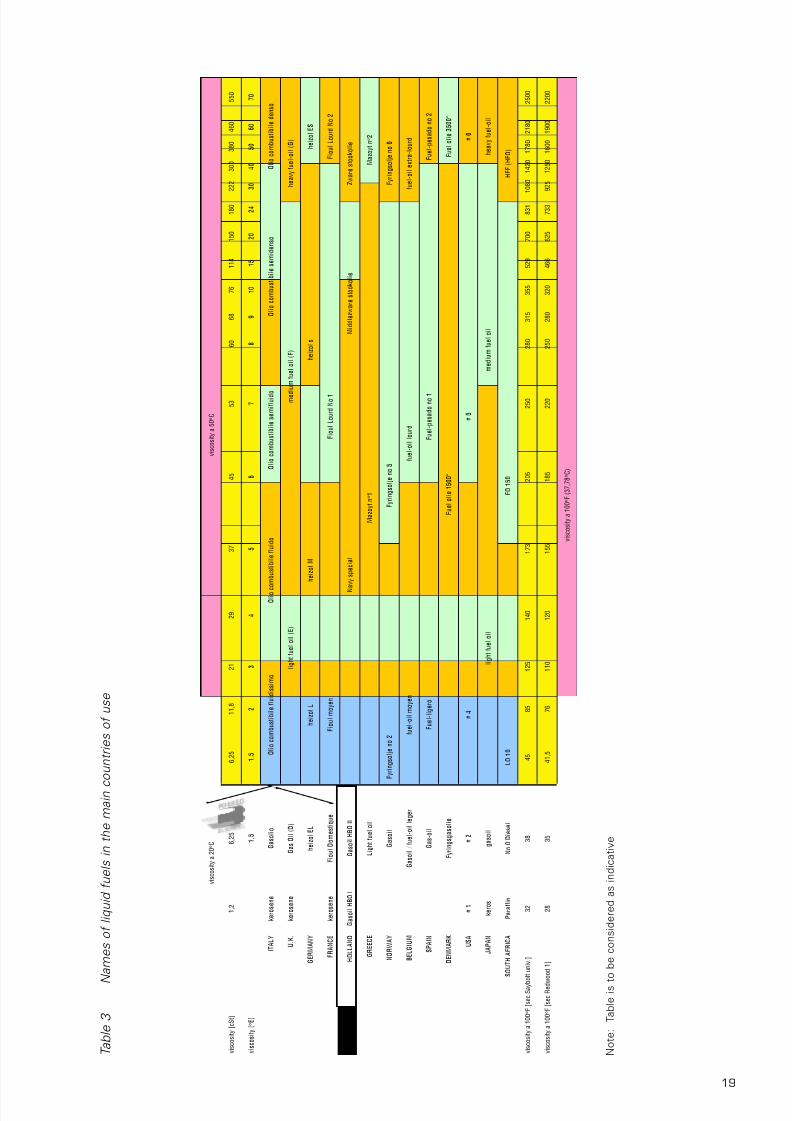
Table 3 - Names of liquid fuels in the main countries of use 19
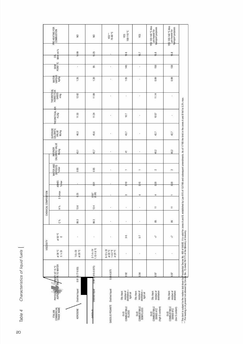
Table 4 - Characteistics of liquid fuels 20
Table 5 - Maximum reccomended values of CO2 for the various fuels 28
Table 6 - Factors for calculation of the combustion efficiency 29
Table 7 - Mass equivalence of ppm of the main pollutant emissions 29
Table 8 - Maximum values of CO2 at 0% and at 3% of O2 for different fuels 30
2 THE FORCED DRAUGHT BURNER 31
Table 9 - Characteristic values of the absolute texture of different pipelines types 46
Table 10 - Maximum pressure drops of gas pipelines 51
Table 11 - Values of the equivalent lenghts of special pieces 52
Table 12 - Example for the tabular calculation of the diameter of the gas pipelines 52
Table 13 - Summary of liquid fuels 56
Table 14 - Schedule for the tabular scaling of the light oil feed pipelines 57
Table 15 - Absolute texture of the pipelines 59
Table 16 - Summary of liquid fuels 61
Table 17 - Typical values of sound power 74
Table 18 - Average values of sound pressure 75
Table 19 - Octave frequency band spectrum 76
Table 20 - Absorption factors of certain materials 77
3 SELECTION OF A FORCED DRAUGHT BURNER 83
Table 21 - Chart of the data required for a combustion system selection 84
Table 22 - F - correction factor of discharge head and delivery in relation to temperature
and altitude 88
Table 23 - Example of backpressure reduction for a burner 88
Table 24 - Chart of the data required for a combustion system selection - example 89
Table 25 - Technical data of RLS series of monoblock burners 90
Table 26 - Iterative process table 90Table 27 - Schedule for the tabular scaling of the light oil feed pipelines 94
Table 28 - Chart of the data required for a combustion system selection - example 95
Table 29 - Technical data of TI series 96
Table 30 - Kc - correction factor of discharge head and delivery in relation to temperature
and altitude 98
Table 31 - Fans selection table 99
Table 32 - Nominal output declassing factor in relation to temperature and altitude 100
Table 33 - High pressure regulating/reducing units selection table 102
Table 34 - Pumping unit skids selection table 102
Table 35 - Nozzles selection table 103
Table 36 - Control panels selection table 107
4 MEASURING COMBUSTION EFFICIENCY 109
Table 37 - Coefficients for calculation of combustion efficiency 111
SUMMARY OF TABLES

7/25/2019 Riello Burner Handbook
http://slidepdf.com/reader/full/riello-burner-handbook 11/16911
PREFACE
With these pages, there has been the intention of collecting, in an only volume, formulas, data and
information useful for who faces problems whom solution involves understanding of combustion
and systems which use forced draught burners for heating production.
The text is divided up into five sections, arranged in logical sequence that permits the reader to first
of all achieve the theoretical fundamentals of the chemistry-physics of combustion and the
manufacturing technique of burners and systems which are closely linked, such as fuel feeding
circuits. Proceeding through the manual, the reader will find examples for the selection and
dimensioning of different types of burners and procedures for measuring the combustion efficiency.
The last section is dedicated to a collection of ready-use tables and diagrams concerning the specific
themes of combustion.
The single chapters can be consulted separately in order to gain knowledge of the specific
procedures and information required for the activities to be performed.
The topics dealt underlie, before legislation, technical-scientific laws; for this reason, legislation is
quoted only in cases of strict necessity. Each reader must therefore check the consistency of the
information contained herein with current legislation in his own country.
With this handbook, Riello wishes to make available an instrument practical and useful, without
claiming to have completely dealt theoretical and installation apsects related to the argument of
combustion systems.
Published from:
RIELLO S.p.A.
Legnago - Italy

7/25/2019 Riello Burner Handbook
http://slidepdf.com/reader/full/riello-burner-handbook 12/16913
1.1 BASIC REACTIONS
Combustion is the rapid oxidation of a fuel. The
reaction is accompanied by that visible
physical phenomenon which is called “flame”
and by the generation of energy that is known
as “heat”.
Carbon combines with oxygen to form carbon
dioxide, a non-toxic gas, and releases heat
according to the following formula:
C + O2 → CO2 + Heat
Likewise, hydrogen combines with oxygen to
form water vapour, with the consequent
production of heat, according to the following
formula:
2H2 + O2 → 2H2 O + Heat
It is important to note that fuel and oxygen
combine in well-defined and specific
proportions. The quantities of oxygen andfuels in the mixture are in perfect or
“stoichiometric” proportion, when they enable
complete oxidation of the fuel without any
oxygen residue.
If there were excess fuel or insufficient
oxygen, we would say the mixture was rich
and the flame was reducing. This type of
combustion is defined as incomplete because,
although certain fuel particles are completely
oxidised by the oxygen, others do not receive
enough oxygen and consequently their
combustion is only partial. As the followingreaction formula indicates, partial or
incomplete carbon combustion is
accompanied by the formation of carbon
monoxide, a highly toxic gas:
2C + O2 → 2CO + Heat
The amount of heat produced here is lower
than that which accompanies perfect
combustion.
Incomplete or reducing combustion is
sometimes required in special industrial,
thermal treatments, but these conditions must
be avoided under any other circumstances.
If, on the other hand, excessive oxygen is
supplied to the mixture, we say the mixture is
weak and combustion is oxidative.
Besides carbon dioxide and water vapour,
other compounds are produced during
combustion in smaller amounts, such as
sulphur oxides, nitric oxides, carbon monoxide
and metallic oxides, which are dealt with
further on.
1.2 THE COMBUSTION SUPPORTER
The oxidative gas normally used is air, which is
a gas mixture mainly made up of oxygen and
nitrogen.
If we know the exact chemical composition of
the fuel we can calculate the stoichiometric
amount of oxygen and consequently the
combustion supporter air required for
combustion purposes.
The expression that provides the amount of
stoichiometric air is as follows:
Wa = 11,51·C + 34,28·H + 4,31·S – 4,32·O
[kgair /kgfuel];
oppure:
Wa = 8,88·C + 26,44·H + 3,33·S – 3,33·O
[Nm3air /kgfuel];
where C, H, S and O are respectively the mass
percentages of carbon, hydrogen, sulphur and
oxygen pertaining to the fuel composition.
In tables 2 and 3, the stoichiometric air
amounts are illustrated of several fuels.
When “excess air” is used, i.e. an amount of
oxygen higher than the stoichiometric amount,
all the nitrogen and the portion of oxygen
FUNDAMENTAL COMBUSTION PRINCIPLES
1
Diagram 1 Elementary representation of a flame

7/25/2019 Riello Burner Handbook
http://slidepdf.com/reader/full/riello-burner-handbook 13/16914
which does not combine with the fuel, do not
participate in the oxidation reaction.
Naturally, they absorb a certain amount of the
heat produced during combustion, therefore
the effective calorific energy is distributed over
a greater volume of gas and the thermal level
is lower (lower flame temperature).
The amount of oxygen contained in the air is
around 21% in volume and approximately 23%
in mass. However, these values are not fixed
but vary in relation to altitude and temperature.
The variations in oxygen concentrations in the
air are due to the fact that heating the
combustion supporter air and an increase in
altitude produce the same effect, i.e. a
reduction in air density. A decrease in air
density corresponds to a decrease in the
amount of oxygen.
At 1,000 metres above sea level, air density is
nearly 10% lower than at 0 metres above sea
level.
The change in air density and, consequently, in
the amount of oxygen, due to a considerable
change in altitude or temperature with respect
to normal conditions (height equal to 100
metres above sea level and a combustion
supporter air temperature of 15°C), is a
parameter which should not be overlooked, as
is better illustrated in section 2 in the
paragraph relating to the examples for
choosing the burner.
In certain conditions, for example when
machinery is being used or other sources that
create large amounts of humidity and steam,
the amount of oxygen in the air could change,
generally decreasing as relative humidity
increases. The presence of dust, fibres in the
intake combustion supporter air could alsocreate problems with the combustion system.
1.3 THE FUELS
A fuel is a substance which reacts with the
oxygen in the air and gives rise to a chemical
reaction with the consequent development of
thermal energy and a small amount of
electromagnetic energy (light), mechanical
energy (noise) and electrical energy (ions andfree electrons).
Fuels can be classified on the basis of the
physical state in which they are commonly
found (solid, liquid or gaseous) and their nature
(they are defined as natural or artificial fuels or
derivatives).
The most commonly used fuels are classified
in table 1 according to the above two criteria.
Natural fuels are concentrated in underground
deposits from where they are extracted for
PhaseProvenance
Natural
Artificial (derivates)
SOLID
Wood, fossil carbons
(pit coal)
Coke, charcoal
LIQUID
Oil
Petrol, kerosene, gasolio,
feul oil
GASEOUS
Natural gas
Methane, propane,
butane, LPG, propane-air
mix, town gas, bio-gas
Diagram 2 Temperature and altitude influence on effective air delivery
Table 1 Principal fuels classification
1000 m a.s.l. 5°CQair = 10,67 mc/h
0 m a.s.l. 5°C Qair = 9,49 mc/h
1000 m a.s.l. 20°CQair = 11,28 mc/h
0 m a.s.l. 20°C Qair = 10 mc/h

7/25/2019 Riello Burner Handbook
http://slidepdf.com/reader/full/riello-burner-handbook 14/16915
extracted from the flue gases produced by
combustion, using a user machine that
condenses the discharge gases.
On the other hand, NCV indicates the
maximum theoretical amount of heat that can
be extracted from the flue gases produced bycombustion using a user machine that does
not condense the discharge gases.
• Theoretical value
This is the minimum quantity of combustion
supporting air theoretically required to achieve
ideal perfect stoichiometric combustion.
This is measured in Nm3 /Nm3 for gaseous fuels
or Nm3 /kg for liquid fuels.
The following principle physical characteristics
are also important for gaseous fuels:
• Air/relative density ratio
This is the ratio of equal volume masses of dry
air and gas measured under the same
temperature and pressure conditions.
• Dew point
The water vapour in the flue gases condenses
at this temperature. This temperature may
vary considerably from the standard value of
100°C, as water vapour is mixed with other
gases and is dependent on the flue gas acidity.It is measured in degrees centigrade (°C).
• Air explosive mixture
This is the gas concentration range, expressed
as a percentage, where the gas and air mixture
is explosive.
• Wobbe Index
A parameter to define the heat released by a
gas, obtained from the relationship between
the gross caloric value and the square root of
the density of the gas with respect to the air.
This index is extremely useful to evaluate the
interchangeability of two different gaseous
fuels: when a certain gas, even if it has
different thermotechnical features from the
basic gas, gives similar values to the Wobbe
index, it can be used correctly in systems that
had been originally designed to work withbasic gas.
W = d
P.C.I.
processing; in fact, natural fuels are not
directly utilisable as their composition is
extremely variable and it is impossible to
guarantee the safety and efficiency of the fuel
beforehand.
Typical processing methods tend to transform
natural fuels into artificial ones.
Charcoal is obtained from wood through slow
and partial combustion inside a charcoal pit
covered with earth.
Distilling low-grade fatty anthracite at a
medium heat produces Coke.
Artificial gaseous fuels can be obtained from
coal through synthesis processes such as dry
distillation, partial oxidisation or reaction with
water vapour.
All artificial liquid and gaseous fuels can beobtained by distilling oil.
Before natural gas can be used, the extremely
pollutant fraction of H2S must be removed,
through desulphurisation, together with the
inert fraction of CO2.
All these processes are aimed at making the
chemical composition of the fuels uniform,
making them easier to use and more
profitable.
In particular, liquid and gas fuels are easily
transportable and can be finely proportioned toguarantee combustion efficiency. For these
reasons, they are preferred in forced draught
burners.
The characteristics that distinguish the fuels
are:
• Calorific value
The definition of the calorific value of a fuel is
the amount of heat developed during total
combustion of the fuel mass unit.
The calorific value is measured in kJ/ Nm3 (1)
for gas and in kJ/kg for liquids and solids.There are two calorific values:
- superior or gross calorific value (GCV) when
all the water present at the end of combustion
is in a liquid state;
- inferior or net calorific value (NCV) when all
the water present at the end of conclusion is in
a gaseous state.
The relationship that ties GCV to NCV is the
following:
GCV=NCV+latent evaporation heat of the
water produced by combustion
GCV therefore indicates the maximumtheoretical amount of heat that can be
(1) A normal cubic meter (1 Nm3) corresponds to a cubic meter of gas at atmospheric pressure (1,013 mbar) and a temperature of 0°C.

7/25/2019 Riello Burner Handbook
http://slidepdf.com/reader/full/riello-burner-handbook 15/16916
The parameter is also useful to calculate
pressure drops (for gas train selection) when a
different gas is used, included among those
allowed as given in the instruction manual for
the burner. Gas pressure drops can be
expressed with the following formula:
For liquid fuels, the following main physical
features are also important:
• Viscosity
This is the intermolecular internal friction of a
fluid, and therefore the macroscopic
dimension that describes the level ofresistance with which the fluid moves.
Dynamic viscosity (or absolute viscosity) is the
tangential force per unit area of two parallel
planes at unit distance apart when the space
between them is filed with a fluid and one
plane moves with unit velocity in its own plane
relative to the other.
The SI unit of measure of dynamic or absolute
viscosity is N·s/m2.
In practice, kinematic viscosity is used,
defined by the absolute viscosity of a fluid
divided by its density.In the SI the kinematic viscosity is measured in
m2 /s; in the technical system it is measured in
cm2 /s; the unit is called "stoke" (St). Often,
instead of the stoke its hundredth part is used,
called centistoke (cSt) equal to mm2 /s.
To measure the liquid viscosity, various
instruments have been perfected, called
viscometers, which have induced numerous
( )∆P 2 = ∆P 1. W 1
W 2
2
units of measure depending on the type of
viscometer and measuring technique.
In Europe, the most common unit of measure
besides the centistoke is the Engler degree
(°E). The Engler viscometer is fundamentally athermostatic container with a gauged hole,
from which 200 cm3 of the tested liquid flows
out and the flow time is measured. The
relationship between this time and the time for
200 cm3 of water to flow out gives the °E
viscosity.
Due to the large number of measuring
instruments and units of measure that are
available, it is difficult to convert the viscosity
levels. Therefore, nomographs and
approximate conversion tables are given in
chapter 5.
• Inflammability flash point
This is the lowest temperature at which a
mixture of air and vapours given off by a liquid
fuel, in the specific conditions established by
legislation and using an adequate primer, is
inflammable. It is measured in degrees
centigrade °C.
• Self-igniting temperature
This is the minimum temperature at which a
mixture of fuel and combustion supporterspontaneously ignites without using a primer.
It is measured in degrees centigrade °C.
1.3.1 Gaseous fuels and theircombustion
As we have seen in the opening paragraphs
concerning combustion, in order to burn, a fuel
it must be mixed with oxygen: the burners
provide fuel gas and combustion supporter airin the right proportions, they mix them and
give rise to their controlled combustion in a
combustion chamber.
Gas burners can be classified according to two
criteria. The first depends on the type of
combustion supporter airflow into the burner
and is classified as follows:
• Natural draught burners;
• Induced drauht burners;
• Forced draught burners.
Natural draught burners use the fuel gas
supply pressure to pull the air through a
Venturi system (normally performed by the
nozzle) so that it is mixed with the fuel gas. AsDiagram 3 Example of a viscometer

7/25/2019 Riello Burner Handbook
http://slidepdf.com/reader/full/riello-burner-handbook 16/16917
a rule, with natural draught burners, the air
flow rate generated by the Venturi effect on
the gas flow (primary air) does not reach more
than 50% of that required for perfect
combustion, therefore a further airflow is
required (secondary air) into the combustionchamber.
These burners can be extremely sensitive to
combustion chamber depression (draught):
greater is the depression, greater is the amount
of air sucked in and mixed with the gaseous
fuel, while, by contrast, a too low depression
causes combustion without air, giving off
extremely dangerous pollutants such as CO.
In order to guarantee consistent hygienically
safe combustion, gas burning in induction
burners usually takes place with high levels of
excess air (100% and over).In order to stabilise the operating conditions
and be able to obtain combustion with lower
excesses of air, induced draught burners are
used, with a fan fitted up-stream (on the air
side) or down-stream (to extract the
combustion products) from the combustion
chamber: in these conditions, primary air can
reach 100% of that required for perfect
combustion.
In forced draught burners, the air flow rate is
guaranteed by elevated head pressure fans
which make the draught operating conditionsmore or less independent of the burner
operation. These can achieve high modulation
ranges and can be combined with high-yield,
and therefore “pressurised” heat generators,
achieving optimum fuel and combustion air
mixtures, making it possible to operate with
low excesses of air and, therefore, increased
combustion efficiency.
In this case, the fuel gas flows together in the
air flow down-stream from the fan through
several nozzles and usually requires greater
delivery pressures than atmospheric burners,both due to the pressure drop by the nozzles
and the need to control the air pressure.
A second criteria to classify burners depends
on the percentage mixture of combustion air
with respect to the fuel taken before
stabilising the flame. The pre-mixing
percentages can be classified as follows:
• Partial pre-mixed gas burners; (e.g.
"premix" = 50%);
• Total pre-mixed gas burners ("premix" =
100%);• Diffusion-flame burners.
In the first two cases, fuel-air mixing takes
place partially or completely, before the
mixture passes onto the combustion chamber:
induction burners are therefore also pre-mix
burners.
The pre-mixing allows rapid fuel oxidationreactions and therefore short flames; a
consistent air-fuel mixture ratio also gives
quieter combustion.
In diffusion-flame burners, the fuel-air mixing
stage and the combustion stage are more or
less simultaneous: to guarantee hygienically
safe combustion with low excesses of air,
increased turbulence is therefore necessary,
thus also, producing high pressure drops on
the air side.
Forced draught burners can be both pre-mixed
or diffusion flame types.Gaseous fuels can form explosive mixtures (2)
with air. This happens when the fuel gas
concentration is within a specific range and is
variable for each individual fuel. To avoid any
accumulation in the combustion chamber and
in the flue pipe, legislation requires a minimum
air only pre-purge time through the
combustion chamber for induced draught
burners.
Table 2 indicates the main gaseous fuels with
their related thermo-technical characteristics.
(2) The explosion is nothing more than rapid combustion with a violent increase of pressure.

7/25/2019 Riello Burner Handbook
http://slidepdf.com/reader/full/riello-burner-handbook 17/16918
T a b l e 2
C
h a r a c t e i s t i c s o f g a s e o u s f u e l s
T H
E R M O T E C H N I C A L C H A R A C T E R I S T I C
S O F T H E M O S T C O M M O N G A S E O U
S F U E L S
T Y P E
N A M E
E N 4 7 6 T Y P E
C H E M I C A L F O R M U
L A
O R
C O M P O S I T I O N
B E H A V I O U R
D E N S I T Y W I T H
R E S P E C T T O
A I R
a t 1 5 ° C
A I R E X
P L O S I V R
M I X T
U R E %
I N F E R I O R
C A L O R I F I C
V A L U E *
M J / N m 3
S U P E R I O R
C A L O R I F I C
V A L U E *
M J / N m 3
T H E O R E T I C A
L A I R
m 3 / N m 3
T H E O R E T I C A L
H U M I D F L U E
G A S E S
m 3 / N m 3
C O
2 M A X .
I N V O L %
W A T E R
V A P O U R I N
F L U E G A S E
S
k g / N m 3
D E W
P O I N T
° C
W O B B E
I N D E X
M J / N m 3
M E T
H A N E
G 2 0
C H
4
L i g h t g a s
0 , 5
5 5
5 ÷ 1 5
3 4 , 0
2
3 7 , 7
8
9 . 5 6
1 0 , 4
4
1 1 , 6
5
1 , 6
1
5 8
4 5 , 8
7
P R O
P A N E
G 3 1
C 3
H 8
H e a v y g a s
1 , 5
5 5
2 . 4
÷ 9 . 3
8 8
9 6 , 6
5
2 4 , 3 7
2 6 , 1
6
1 3 , 7
3 , 2
9
5 4
7 7 , 5
1
P U R E G A S
B U T
A N E
G 3 0
C 4
H 1 0
H e a v y g a s
2 , 0
9 4
2 ÷ 7 . 6
1 1 6 , 0
9
1 2 5 , 8
1
3 2 , 3 7
3 4 , 6
6
1 4
4 . 2
0
5 3
8 0 , 2
2
N A T
U R A L G A S
G 2 5
E x a m p l e :
C H
4 8 6 %
N 2
1 4 %
H e a v y g a s
2 9 , 2
5
3 2 , 4
9
3 7 , 3
9
L P G
-
E x a m p l e :
P r o p a n o 7 0 %
B u t a n o 3 0 %
H e a v y g a s
1 , 6
8 6
2 . 1
÷ 9 . 5
1 0 1 , 6
1 1 0 , 4
2 6 . 3 2
2 8 . 2
3
1 3 , 7
4
3 . 5
1
5 4
7 8 , 2
5
P R O
P A N E A I R - M
I X
-
E x a m p l e :
G a s 2 6 . 2
% /
A i r 7 3 . 8 %
G a s c o m p o s i t i o n :
P r o p a n e 9 5 %
/ B u t a n e
5 %
L i g h t g a s
1 , 1
4 9
7 . 5 ÷ 3 6
2 4 , 7
2 6 , 9
5 , 7 5
6 , 9
6
1 3 , 6
7
0 , 8
7
5 4
2 3 , 0
4
T O W
N G A S
-
E x a m p l e :
H 2 5 4 . 5
%
C O 5 . 5
%
C H
4 2 4 . 4
% e
t c .
L i g h t g a s
0 , 3
9 7
5 ÷ 3 0
2 0 , 9
2 3 , 6
4 , 3 3
4 , 9
8
1 0 , 0
3
0 , 9
2
6 2
3 3 , 1
7
M I X T U R E S
B I O G A S
-
E x a m p l e :
M e t h a n e 6 4 %
C a r b o n e d i o x i d e 3 4 . 6 %
N i t r o g e n 1 . 2
%
H y d r o g e n 0 . 2
%
L i g h t g a s
0 , 8
9 6
7 . 8 ÷ 2 3 . 4
2 3
2 5 , 5
6 . 1 2
7 , 0
5
1 6 , 8
5
1 , 0
3
5 7
2 4 , 3
* T h e c a l o r i f i c v a l u e r e
f e r s t o t h e n o r m a l c u b i c m e t e r ( N m 3 ) , i . e .
t o 1 m 3
o f g a s a t a t m o s p h e r i c p r e s s u r e a n d a t 0 ° C .
T h e m 3
s t a n d a r d ( s t m 3 ) o f
g a s f i t t e r s o n t h e o t h e r h a n d r e f e r s t o 1 5 ° C .
1 s t m 3
g i v e s 8 2
0 0 k c a l . I n m e a s u r m e n t s m a d e w i t h g a s c o u n t e r i t i s a d v i s a b l e t o r e f e r t o t h e s t a n d a r d m 3 .
7/25/2019 Riello Burner Handbook
http://slidepdf.com/reader/full/riello-burner-handbook 18/16919
T a b l e 3
N
a m e s o f l i q u i d f u e l s i n t h e m a i n c
o u n t r i e s o f u s e
v i s c o s i t y [ c S t ]
1 , 2
6 , 2
5
6 , 2
5
1 1 , 8
2 1
2 9
3 7
4 5
5 3
6 0
6 8
7 6
1 1 4
1 5 0
1 8 0
2 2 2
3 0 0
3 8 0
4 6 0
5 5 0
v i s c o s i t y [ ° E ]
1 , 5
1 , 5
2
3
4
5
6
7
8
9
1 0
1 5
2 0
2 4
3 0
4 0
5 0
6 0
7 0
I T A L Y
k e r o s e n e
G a s o l i o
U . K .
k e r o s e n e
G a s O i l ( D )
G E R M A N Y
h e i z o l E L
F R A N C E
k e r o s e n e
F i o u l D o m e s t i q u e
H O L L A N D
G a s o i l H B O I
G a s o i l H B O I I
G R E E C E
L i g h t f u e l o i l
N O R W A Y
G a s o i l
F y r i n g s o l j e n o 2
B E L G I U M
G a s o i l / f u e l - o i l l e g e r
S P A I N
G a s - o i l
D E N M A R K
F y r i n g s g a s o l i e
U S A
# 1
# 2
J A P A N
k e r o s
g a s o i l
S O U T H A F R I C A
P a r a f f i n
N o 0 D i e s e l
L O 1 0
v i s c o s i t y a 1 0 0 ° F [ s e c S a y b
o l t u n i v . ]
3 2
3 8
4 5
8 5
1 2 5
1 4 0
1 7 3
2 0 5
2 5 0
2 8 0
3 1 5
3 5 5
5 2 9
7 0 0
8 3 1
1 0 8 0
1 4 2 0
1 7 8 0
2 1 8 0
2 5 0 0
v i s c o s i t y a 1 0 0 ° F [ s e c R e d w
o o d 1 ]
2 8
3 5
4 1 , 5
7 6
1 1 0
1 2 0
1 5 5
1 8 5
2 2 0
2 5 0
2 8 0
3 2 0
4 6 6
6 2 5
7 3 3
9 2 5
1 2 5 0
1 6 0 0
1 9 0 0
2 2 0 0
v i s c o s i t y a 1 0 0 ° F ( 3 7 , 7
8 ° C )
l i g h t f u e l o i l
m e d i u m
f u e l o i l
h e a v y f u e l - o i l
F O 1 5 0
H F F ( H F O )
F u e l o l i e 1 5 0 0 "
F u e l o l i e 3 5 0 0 "
# 4
# 5
# 6
f u e l - o i l m o y e n
f u e l - o i l l o u r d
f u e l - o i l e x t r a - l o u r d
F u e l - l i g e r o
F u e l - p e s a d o n o 1
F u e l - p e s a d o n o 2
M a z o y t n ° 1
M a z o y t n ° 2
F y r i n g s o l j e n o 5
F y r i n g s o l j e n o 6
F i o u l m o y e n
F i o u l L o u r d N o 1
F i o u l L o u r d N o 2
N a v y s p e c i a l
M i d d l e z w a r e s t o o k o l i e
Z w a r e s t o o k o l i e
l i g h t f u e l o i l ( E )
m e d
i u m
f u e l o i l ( F )
h e a v y f u e l - o i l ( G )
h e i z o l L
h e i z o l M
h e i z o l s
h e i z o l E S
v i s c o s i t y a 2 0 ° C
v i s c o s i t y a 5 0 ° C
O l i o c o m b u s t i b i l e f l u i d i s s i m o
O l i o c
o m b u s t i b i l e f l u i d o
O l i o c o m b u s t i b i l e s e m i f l u i d o
O l i o c o m b u s t i b i l e s e m i d e n s o
O l i o c o m b u s t i b i l e d e n s o
N o
t e :
T a b l e i s t
o b e c o n s
i d e r e
d a s
i n d i c a
t i v e
7/25/2019 Riello Burner Handbook
http://slidepdf.com/reader/full/riello-burner-handbook 19/16920
T a b l e 4
C h a r a c t e r i s t i c s o f l i q u i d f u e l s
V I S C O S I T Y
C H E M I C A L C O M P O S I T I O N
I T A L I A N
C O M M E R C I A L
T R A D E N A M E
P H Y S I C A L
A S P E C T
D E N S I T Y A T 1 5 ° C
R E L A T I V E T O W A T E R
a t 3 8 ° C
E / c S t
a t 5 0 ° C
E
C %
H %
S % r n a x
A S H E S
% m a x
W A T E R A N D
D E P O S I T S
% m a x
I N F E R I O R
C A L O R I F I C V A L U E
M J / k g
S U P E R I O R
C A L O R I F I C
V A L U E
M J / k g
T H E O R E T I C A L A I R
m 3
/ k g
T H E O R E T I C A L
H U M I D F L U E
G A S E S
m / k g
W A T E R
V A P O U R
k g / k g
D E W
P O I N T ° C
C O
2
M A X v o l . %
P R E - H
E A T I N G F O R
C O M B U S T I O N
K E R O S E N E
D
i s t i l l e d l i q u i d
0 . 8
1 ( 0 . 7
7 - 0 . 8
3 )
1 . 6
c S t
a t 2 0 ° C
-
8 6 . 3
1 3 . 6
0 . 2
5
-
0 . 0
5
4 3 , 1
4 6 , 3
1 1 . 3
3
1 2 . 0
2
1 . 2
6
-
1 4 . 9
9
N O
G A S O L I O
D
i s t i l l e d l i q u i d
0 . 8
4 ( 0 . 8
1 5 - 0 . 8
7 5 )
2 - 7 . 4
c S t
1 . 1
2 - 1 . 6
° E
-
8 6 . 3
1 3 . 4
0 . 5
0 *
( 0 . 3
0 )
0 . 0
1
0 . 0
5
4 2 , 7
4 5 , 6
1 1 . 2
4
1 1 . 8
9
1 . 2
0
9 5
1 5 . 2
5
N O
G A S O L I O P E S A N T E
D
i s t i l l e d l i q u i d
0 . 8
6 - 0 . 8
7 5
6 - 1
2 c S t
a t 2 0 ° C
1 . 4 - 2 ° E
a t 2 0 ° C
-
-
-
-
-
-
-
-
-
-
-
-
-
Y E S * *
7 0 - 8
0 ° C
O L I O
C O M B U S T I B I L E
F L U I D O
O i l y b l a c k
r e s i d u e o f
d i s t i l l a t i o n +
l i g h t o i l
0 . 9
2
-
3 - 5
-
-
3
0 . 1
0
1
4 1
4 3 , 7
1 0 . 7
-
1 . 0
5
1 4 5
1 5 . 6
Y E S
1 0 0 - 1
1 0 ° C
O L I O
C O M B U S T I B I L E
S E M I F L U I D O
O i l y b l a c k
r e s i d u e o f
d i s t i l l a t i o n +
l i g h t o i l
0 . 9
4
-
5 - 7
-
-
4
0 . 1
5
1
-
-
-
-
-
-
1 5 . 7
Y E S
O L I O
C O M B U S T I B I L E
D E N S O A T Z
( h i g h S c o n t e n t )
O i l y b l a c k
r e s i d u e o f
d i s t i l l a t i o n
0 . 9
7
-
> 7
8 5
1 1
4
0 . 2
0
2
4 0 , 2
4 2 , 7
1 0 . 5
7
1 1 , 1
4
0 . 9
9
1 5 0
1 5 . 8
Y E S 1 2 0 - 1
4 0 ° C A l s o
p r e - h e a t e d f o r
t r a n s p o r t p u r p o s e s
O L I O
C O M B U S T I B I L E
D E N S O B T Z
( l o w S c o n t e n t )
O i l y b l a c k
r e s i d u e o f
d i s t i l l a t i o n
0 . 9
7
-
> 7
8 5
1 1
1
0 . 2
0
2
4 0 , 2
4 2 , 7
-
-
0 . 9
9
1 3 0
1 5 . 8
Y E S 1 2 0 - 1
4 0 ° C A l s o
p r e - h e a t e d f o r
t r a n s p o r t p u r p o s e s
* T h i s l i m i t i s s u b j e c t t o
t h e m a t t e r s l a i d d o w n b y P r e s i d e n t i a l D e c r e e N o .
4 0 0 o f 8 / 6 / 8 2 . I t i s v a l i d f o r z o n e s A a n d B ,
e s t a b l i s h e d b y L a w 6 1 5 o f 1 3 / 7 / 6 6 a n d s u b s e q u e n t a m e n d m e n t s .
A s o f 1 / 7 / 8 5 t h e l i m i t i n t h e z o n e s A
a n d B f e l l t o 0 . 3
% m
a x .
* * P r e - h e a t i n g i s a t p r e s
e n t n o t a l l o w e d b y C i r c u l a r N o .
7 3 d a t e d 2 9 / 7 / 7 1 o f t h e M i n i s t r y
o f I n d u s t r y

7/25/2019 Riello Burner Handbook
http://slidepdf.com/reader/full/riello-burner-handbook 20/16921
1.3.2 Liquid fuels and theircombustion
Liquid fuels are made up of various types of
hydrocarbons, i.e. molecules formed by carbon
and hydrogen atoms. Unlike gaseous fuels,liquid fuels contain molecules of extremely
long-chain hydrocarbons giving oils a liquid
physical state.
Liquid fuels cannot be directly mixed with the
oxygen in the air, but must be atomised in
extremely small droplets that have a
considerable reaction surface.
Inside the generator combustion chamber, the
droplets of atomised liquid fuel heat up and
evaporate releasing hydrocarbon vapours that
ensure spontaneous fuel combustion.
For combustion to be perfect, the drops ofliquid fuel must be oxidised within the body of
the flame; if not, the drops form particles of
particulate, as more fully illustrated in the next
paragraph on pollutants.
Atomisation of liquid fuel is one of the main
tasks performed by a burner. There are several
atomisation methods for liquid fuels. The main
ones are listed below:
• Mechanical atomisation;
• Pneumatic atomisation;
• Centrifugal atomisation;
The most common method is “mechanical
atomisation” where liquid fuel atomisation is
the result of the mechanical pressure exerted
on the liquid, when it reaches the atomising
nozzle, against the walls made up of small run
channels and helicoidal holes in the nozzle.
With this method, the fuel oil is split into a
great deal of extremely small droplets due to
brusque flow variations and impact against the
walls due to high pressure (10-30 bar). The size
of the droplets depends on the exerted
pressure, the type of nozzle and the viscosity.Another system is the “pneumatic system”
where the droplets of liquid fuel are further
atomised by a second high-pressure fluid
(compressed air or vapour) when they come
out from the mechanical nozzle. This system
guarantees excellent fuel atomisation levels
for dense fuel oils, but at the same time more
complicated construction, with auxiliary liquid
being present (working pressure 5-9 bar) and
consequently higher installation cost
compared to the classic mechanical method.
In rotary atomisation, the drops of fuel areformed by applying a centrifugal force to the
liquid fuel with the aid of a rotating cup; this
method is used for certain industrial-type
burners.
On today's market, systems are available
aimed at improving the mechanical-type
atomisation system using modified fuels;
basically, fuel oil and water emulsions are
used. The individual drops of fuel oil are
emulsified into water droplets that, within thebody of the flame, become water vapour
causing the fuel oil drops to explode.
Therefore more efficient fuel atomisation
results.
Independently from the type used for
achieving a satisfactory atomisation degree,
the liquid fuel must have a sufficiently low
viscosity.
The viscosity of liquid fuel is strictly linked to
the temperature; when the temperature
increases the viscosity decreases. Therefore,
certain liquid fuels must be pre-heated toachieve the desired viscosity.
As a rule, fuel oil viscosity required for
achieving satisfactory atomisation is much
lower than that requested by pumping
systems, consequently a much higher
temperature is required to achieve adequate
atomisation than that requested for pumping
the fluid. All these aspects translate into
specific plant engineering choices that are fully
covered in the section dedicated to plant
engineering.The viscosity required for obtaining sufficient
fuel oil atomisation varies according to the
type of burner and type of nozzle used.
Generally, the nozzles require oil viscosity
between 1.5 and 5 °E at 50°C in relation to the
type of fuel. This viscosity value also
determines the pre-heating temperature value.
For example: supposing we use a fuel oil with
viscosity of 22°E at 50°C to obtain a value of
3°E needed by the nozzle to obtain the right
atomisation, the fuel must be pre-heated to a
temperature between 90 and 100°C.
Table 3 gives the names used for liquid fuels in
the main countries, while Table 4 shows the
related thermotechnical characteristics.
1.4 POLLUTANT COMBUSTION
EMISSIONS
The leading polluting agents to be considered
in the combustion phenomenon are:• sulphur oxides, generally indicated by SOx
and mainly made up of sulphur dioxide SO2and sulphur trioxide SO3;
• nitric oxides, generally indicated by NOx

7/25/2019 Riello Burner Handbook
http://slidepdf.com/reader/full/riello-burner-handbook 21/16922
and mainly made up of nitric oxide NO and
nitrogen dioxide NO2;
• carbon monoxide CO;
• total suspended particles indicated by TSP
(PST).
There are essentially three systems that can
be adopted to reduce the pollutants:
• preventive systems, by acting on the fuel
before subjecting it to combustion, trying to
reduce the amount of polluting agents. A
typical case is represented by liquid fuels (light
oil and naphtha) where the sulphur contenttends to be reduced;
• primary systems, by acting on the process
and combustion equipment (burner), so that
combustion takes place under the best
conditions thus reducing the formation of
pollutants;
• secondary system, by acting on the
combustion gases, to break down the polluting
components before they are expelled into the
atmosphere.
During the design and the construction of civilengineering combustion plants, the first two
systems should be used to reduce pollutants,
therefore using “clean” fuels, gas, LPG, light
oil and naphtha with a low sulphur (BTZ oil) and
nitrogen content, and using special burners to
minimise the polluting emissions of nitric
oxides (Low-NOx burners);
The third system is recommended for use only
in large industrial and thermoelectric plants,
which mainly work with naphtha, where the
large amount of burnt fuel and, consequently,
emitted combusted gases justify the creationof specific breakdown plants.
1.4.1 Sulphur oxides
Sulphur oxides are considered toxic for man;
especially sulphur dioxide SO2 causes
irritation of the eyes and lachrymation when
the concentration exceeds 300 mg/Nm3
. Thedanger threshold is estimated at around 500
mg/Nm3.
Moderate temperatures favour the formation
of sulphur oxides. Under normal conditions of
high combustion flame temperature and
excess air around 20%, nearly all the sulphur
present in the fuel oxidises into sulphur
dioxide (SO2).
Sulphur dioxide is a colourless gas with a
density equal to nearly two and a half that of
air, therefore it tends to stratify towards theground in closed environments.
The percentage of sulphur trioxide SO3 may
become important for low combustion
temperatures (400°C), for example in start-up
phases of installations, or when the excess air
is extremely high or even when pure oxygen is
used.
Sulphur trioxide SO3 reacts with water vapour,
generating sulphuric acid H2SO4 that is
corrosive even in the vaporous phase, thus
damaging for heat generators, which are
usually metallic.Measures for controlling sulphur dioxide SO2and sulphur trioxide SO3 emissions are first of
all based on preventive action on fuels during
their production, by using catalytic
desulphurisation processes.
In large heavy oil-operated plants, the
breakdown of nitric oxides is mainly by
absorption using water-based solutions, which
can achieve yields of around 90%.
1.4.2 Nitric oxides
Nitric monoxide NO is a colourless, odourless
gas which is insoluble in water. It represents
more than 90% of all nitric oxides formed
during high-temperature combustion
processes; it is not particularly toxic when its
concentration ranges between 10 and 50 ppm.
and it is non-irritant.
Nitrogen dioxide NO2 is a visible gas even in
low concentrations, with a browny-reddish
colour and a particularly acrid smell; it is highlycorrosive and an irritant to the nasal
membranes and eyes when concentrated at
10 ppm, while causing bronchitis at
concentrations of 150 ppm and pulmonary
Diagram 4 Acid rain formation process
Sun-light
Oxidation Dissolution
Dry deposition Wet deposition
Source ofemission
Dry depositionof gas, dust and
aereosol
Naturalammonia
Humid deposition ofdissolved acids

7/25/2019 Riello Burner Handbook
http://slidepdf.com/reader/full/riello-burner-handbook 22/16923
oedema at 500 ppm, even if exposure lasts
just a few minutes.
The nitric monoxide NO present in our city air
can transform itself into nitrogen dioxide NO2by means of photochemical oxidation.
Three models of nitric oxide formation exist,which lead to the formation of different types
of nitric oxide (different by type of origin but
not by chemical composition); respectively
they are:
• thermal nitric oxides (thermal NOx);
• prompt nitric oxides (prompt NOx);
• fuel nitric oxides (fuel NOx);
Thermal nitric oxides are formed by the
oxidation of atmospheric nitrogen (contained in
combustion supporter air) under high
temperature (T>1500 K) and high oxygen
concentration conditions, and represent themajority of nitric oxides in the case of gaseous
fuels (methane and LPG) and in general in
fuels which do not contain nitrogenous
compounds.
Prompt nitric oxides are formed by means of
the fixation of atmospheric nitrogen by
hydrocarbon fragments (radicals) present in
the flame area; this method of forming oxides
is extremely rapid thus giving rise to the name
prompt.
Their formation essentially depends on the
concentration of radicals in the first stage ofthe flame; for oxidative flames (combustion
with excess of oxygen), their contribution is
negligible, while in the case of rich mixtures
and for low-temperature combustion, their
contribution may reach 25% of the full nitric
oxides total.
Nitric oxides from fuel form by means of
oxidation of the nitrogenous compounds
contained in the fuel within the flame area, and
their production is significant when the fuel’s
nitrogen content exceeds 0.1% in weight,
essentially only for liquid and solid fuels.Diagram 5 shows the contribution for each
type of NOx depending on the type of fuel
(under conditions of standard combustion):
The portion of prompt nitric oxides remains
more or less constant, whereas the portion of
fuel nitric oxides grows and the portion of
thermal nitric oxides decreases as we
gradually pass to fuels with a higher molecular
weight.
1.4.2.1 Reduction of the NOx in
gaseous fuel combustion
The thermal nitric oxides in gaseous fuels
represent up to 80% of total emissions; a drop
in the combustion temperature achieves
inhibition of the formation of these
compounds.
The temperature drop may be carried out invarious ways.
- specific thermal load reduction
An initial method involves decreasing the
output burnt per unit of volume of the
combustion chamber, resorting in fact to a
“de-rating” of the boiler and thereby
decreasing its nominal thermal capacity (if it is
an existing boiler) or over-sizing the
combustion chamber for new projects.
- combustion chamber architecture
Another solution that can be adopted involves
the use of heat generators, which havecombustion chamber architecture with three
flue passes, in other words without inversion
of the flame. In flame-inversion boilers, the
combustion products re-ascend the
combustion chamber during the flow inversion
stage, confining the actual flame within an
effectively smaller volume than that of the
combustion chamber; a portion of the radiant
energy possessed is also reflected towards
the flame itself. These conditions lead to a
flame temperature increase, with a
consequent increase in the thermal nitricoxides. The same situation occurs in
applications where the chamber wall
temperatures are high, i.e. in furnaces or in
boilers with fluid at high temperatures.
- air and gas pre-mixing
Under normal conditions the combustion
systems are calibrated so that they can
operate with excess air; this excess air
establishes a lower effective combustion
temperature than the adiabatic temperature
and sometimes one that is lower than the limit
which enables activation of the nitric oxideformation mechanism (1500 K).
Since the flame is a typically turbulent domain
fed by two reactants that are difficult to mix
perfectly, it is normal that zones with differentDiagram 5 Type of NOx for certain fuels
gas light oil heavy oil carbon
Fuel
Prompt
Thermal
N2 “fuel” (mass %)
T o t a l ( % )

7/25/2019 Riello Burner Handbook
http://slidepdf.com/reader/full/riello-burner-handbook 23/16924
stoichiometry are formed therein. These will
inevitably include zones with stoichiometric
conditions or approximate to stoichiometric
conditions: the temperatures in these regions
will, without doubt, be so high that they will
give rise to conditions suitable for thermal NOxformation.
These observations suggest action which
could impede, or at least reduce, such
situations: pre-mix the air and gas accurately
before combustion and develop the latter
without excessive turbulence, in such a way as
to come close to the stoichiometric conditions
which would result in the required excess air
(and therefore come close to the theoretical
combustion temperature which can be derived
from the stoichiometric one) whatever the
region effected by combustion.An additional, positive contribution may be
provided by uniform flame distribution- better
still if this distribution covers wide surface
areas - which also prevents the presence of
small tongues of flame, inside which the
temperatures would certainly be higher.
Examples of these techniques are represented
by porous surface areas (in metallic or ceramic
materials) or those comprising masses of
fibres or characterised by the presence of tiny
microscopic holes: up-stream from these
surfaces, attempts are made to create anaccurate as possible pre-mixing, while on the
external surfaces the objective is to obtain a
region of flame which is fairly uniformly
extended and distributed.
This technique appears the most promising in
absolute terms for Low NOx gas solutions,
even if for now the high costs involved and
certain constructive restrictions hinder its use,
especially in the field of higher outputs.
- staged combustion
The nitric oxide formation speed is greater
when in proximity to a ratio of fuel tocombustion supporter, which is equal to the
stoichiometric ratio. In order to obtain low
nitric oxide formation speeds, it is possible to
operate with a combustion system which on
average operates with realistic excess air, but
which presents internal zones with ratios
between fuel and combustion supporter which
are extremely different from the stoichiometric
one, thereby resorting to a segregation of the
fuel. As far as application is concerned, the
aerodynamics of the flame and the fuel
distribution can be adjusted, creating zoneshigh in excess of air alternated with zones
without, thus maintaining the global
stoichiometry under correct operating
conditions.
- combustion products blow-by
By diluting a portion of the burnt gases in the
combustion supporter air, a decrease in the
combustion supporter oxygen concentration is
obtained together with a reduction of the
flame temperature since part of the energydeveloped by combustion is immediately
transferred to the inerts present in the fuel
gas.
The breakdowns achievable by means of this
technique are extremely high in the case of
gaseous fuels, because of ensuring a
sufficient mixing between the blown-by
combustion products and the combustion
supporter/fuel mixture.
It is relatively easy to active a blow-by of the
combustion products in the flame directly
within the chamber in the case of thermalgenerators, and therefore burners, with low
outputs by resorting again to particular
aerodynamics induced by the burner
combustion head, As a rule these internal
blow-bys are extremely high (around 50 %)
because the fuel/combustion supporter
reactants mixing is less effective and the flue
gas temperature is relatively high (900 ÷ 1000
K).
Sometimes, it is preferable to resort to an
external blow-by of the combustion productsfor machines with a greater output due to the
difficulties in obtaining this mixing, which only
add to the aggravation of other problems (for
example: the elevated combustion head load
Diagram 6 Functional layout of combustion
process for a gas burner - Blue flame type.
1 Comburent air - 2 Fuel gas intake - 3 Fuel gas jets-
4 Flame stabilization zone (combustion under
stoichiometrics) - 5 Recirculed combustion products
- 6 Over stoichiometrics combustion - mixture of
fuel air, gas and recirculed combustion products - 7
“Cold” zone of the flame.

7/25/2019 Riello Burner Handbook
http://slidepdf.com/reader/full/riello-burner-handbook 24/16925
losses).By means of an auxiliary fan, or by utilising the
burner fan itself, a portion of the combustion
products is withdrawn at the heat generator
outlet and is re-conveyed up-stream from the
combustion head, so as to pre-mix it with the
combustion supporter air.
Even if in certain situations, a blow-by inside
the combustion chamber may not be enough
for extremely low NOx emission values (and
this is the case now mentioned regarding high
output burners), this technique may be appliedin association with the staged combustion
technique illustrated previously.
1.4.2.2 Reduction of the NOx in liquid
fuel combustion
The substantial difference - within certain
limits of the nitric oxides argument - between
the combustion of gas and the combustion of
liquid fuels, is the presence in the latter ofnitrogen under the guise of nitrogenous
compounds; this is at the origin of NOx
production from fuels which, dependent on
the nitrogen content in the oil, may also
represent a significant portion of the total NOx.
As far as thermal and prompt nitric oxides are
concerned, the same observations expressed
in the case of gaseous fuels (discussed
previously) apply.
With regard to nitric oxides from fuels, it has
been observed that in reducing environments
the nitrogen contained in the fuel may notproduce the undesired NOx, but simple and
harmless molecular nitrogen N2.
The combustion chamber is an environment
devoted to the oxidation of fuel; however, it is
possible to create zones rich in fuel in certain
regions of the flame and therefore form
reducing situations for the purpose of
producing molecular nitrogen N2 in the place
of nitric oxides.
For example, steps could be taken to supplythe initial combustion region with 80 % of the
total combustion supporter air together with
100 % of the fuel and, further on, supply the
remaining 20 % of the combustion supporter
air (over firing air).
These applications are still considered to be in
the experimental stages for burners used in
the sectors of standard heating systems. By
contrast, these techniques are already a
consolidated asset in the industrial systems of
thermoelectric power stations.
1.4.3 Carbon monoxide (CO)
Carbon monoxide is a colourless, odourless
and tasteless gas. Its relative density
compared to air is 0.96, therefore it does not
Monobloc burner (light oil - Low NOx)
of BGK series
Diagram 7
Effects of carbon monoxide Diagram 8
Hours of exposure
Death
Danger
of death
Cefhalea, nausea
Slight ailments
Insignificant effects
V o l u m e p e r c e n t a g e o f C O 2 i n t h e a i r

7/25/2019 Riello Burner Handbook
http://slidepdf.com/reader/full/riello-burner-handbook 25/16926
disperse with ease.
Carbon monoxide is a toxic gas which, if
inhaled, reacts extremely rapidly with the
haemoglobin in the blood, preventing the
regular oxygenation of the blood and, as a
consequence, of the entire organism.The physiological effects on the organism are
the result of the concentration of the carbon
monoxide in the air and the length of exposure
of the person to said concentration.
The diagram 8 illustrates the effects of carbon
monoxide in relation to the two previously
mentioned parameters.
Carbon monoxide is present in combustion gas
as the result of the partial oxidation of the
carbon present in the fuel. Its presence in
burnt gases is an indication of low combustionefficiency, because the carbon not perfectly
oxidised to CO2 corresponds to heat not
produced.
Carbon monoxide is present in burnt gases
when combustion is carried out with too little
air than is required stoichiometrically and
therefore the oxygen is insufficient for the
purposes of completing the carbon oxidation
reactions. Heating systems are responsible to
a minimum extent for the presence of carbon
monoxide in the atmosphere, since the
combustion processes are usually conductedwith excess air higher than the stoichiometric
requirements.
1.4.4 Total suspended particles
This category of polluting substances includes
those emissions comprising particulates, inert
solid substances and metallic components.
The size of these particles varies from a
minimum of 0.01 microns up to a maximum of500 microns.
The particulate may be of an organic or
inorganic nature; in more detail, three
categories can be identified:
• Ashes, comprising inorganic,
incombustible substances (metals, etc..),
drawn into the combustion gases;
• Gas black, made up of the fuel residues
which have evaporated but not oxidised;
• Cenopheres, comprising fuel residues that
have been partially oxidised since they have
been burnt before vaporising.The finest portion of the particulate is called
soot.
The danger of the particles is inversely
proportionate to the size. Damage caused is
mainly to the respiratory tracts and pulmonary
system.
The diagram 9 indicates the depth these
particles can penetrate the human body
according to their size.
Furthermore, in the pulmonary alveolus the
particulate acts as the vehicle transporting the
metallic oxides (vanadium, nickel etc..) which
may be produced during combustion and
which are absorbed by the particles of the
particulate.Only the particles with an equivalent diameter
smaller than 10 microns are sufficiently light to
remain suspended in the air for several hours
and therefore represent real danger of being
inhaled by man.
Metal oxide emissions depend on the
concentration of the respective metals in the
fuel, therefore for civil installations the best
solution for reducing emission essentially
involves the utilisation of fuels with low heavy
metals concentrations.
Gas black is usually produced in particularareas of the flame where there are insufficient
oxygen or low temperature conditions;
therefore, in order to avoid the formation of
gas black it is necessary to guarantee the
combustion process an adequate temperature,
a sufficient quantity of oxygen and
considerable turbulence in order to obtain a
satisfactory mix between the fuel and the
oxygen.
Cenospheres form when the nebulisation and
volatilisation process of the liquid fuels in the
combustion chamber is irregular or hinderedby the elevated viscosity and low volatility of
the fuel.
In order to reduce the production of these
components, it is necessary to increase the
Penetration of the particles in the
respiratory system
Diagram 9
Nose
Pharynx
Primary bronchus
Secondary Bronchus
Terminal bronchus
Alveolus

7/25/2019 Riello Burner Handbook
http://slidepdf.com/reader/full/riello-burner-handbook 26/16927
period spent in the combustion chamber and
guarantee the fuel an adequate excess of
oxygen.
The maximum concentration of the pollutants
in the flue gases deriving from combustion, is
a value fixed by national legislation and incertain cases differs in relation to particularly
sensitive regions and/or metropolitan areas.
1.4.5 Comments on the emissionof CO2
Carbon dioxide CO2 was purposefully not
included among the other pollutants
mentioned since, together with water vapour,
it is one of the main products of anyhydrocarbon combustion process.
The accumulation of carbon dioxide in the
atmosphere is the main culprit of the
phenomenon known as the “greenhouse
effect”. Accumulated carbon dioxide absorbs
part of the infrared radiation emitted by the
earth towards the atmosphere, thus retaining
the heat. The outcome of this phenomenon is
the progressive increase in the Earth’s average
temperature with disastrous resulting
consequences.
The absolute carbon dioxide quantity producedby combustion depends solely on the quantity
of carbon C present originally in the burnt fuel.
The greater the C/H ratio of the fuel, the
greater the quantity of carbon dioxide
produced will be.
As a rule, all energy produced being equal,
liquid fuels produce more carbon dioxide than
gaseous fuels.
As we will see in the next section concerning
the control of combustion, the percentage of
CO2 in the flue gases must be as high as
possible to achieve greater output.All energy produced being equal, a lower CO2percentage in the combustion flue gases leads
to the system being less efficient and, as a
consequence, more fuel being oxidised.
This fact should not mislead the reader
however, since even if we vary the percentage
of CO2 in the flue gases in relation to the
dilution of the flue gases, the total quantity of
CO2 remains more or less unchanged.
1.5 COMBUSTION CONTROL
For combustion to be perfect, a quantity of air
must be used greater than the theoretical
quantity of air anticipated by the chemical
reactions (stoichiometric air).
This increase is due to the need to oxidise all
the available fuel, avoiding the possibility that
fuel particles are only partially oxidised or
completely unburnt.The difference between the quantity of real air
and stoichiometric air is defined as excess air.
As a rule, excess air varies between 5% and
50%, in excess of stoichiometric depending on
the type of fuel and burner.
Generally, the more difficult the fuel is to
oxidise, the greater the amount of excess air
required to achieve perfect combustion.
The excess air cannot be too high because it
influences combustion efficiency; an
extremely large delivery of combustion
supporter air dilutes the flue gases, whichlowers the temperature and increases the
thermal loss from the generator. In addition,
beyond certain limits of excess air, the flame
cools excessively with the consequent
formation of CO and unburnt materials. Vice
versa, an insufficient amount of air causes
incomplete combustion with the previously
mentioned problems. Therefore, the excess air
must be correctly calibrated to guarantee
perfect fuel combustion and ensure elevated
combustion efficiency.
Complete and perfect combustion is verified
by analysing the carbon monoxide CO in the
burnt flue gases. If there is no CO, combustion
is complete.
The excess air level can be indirectly obtained
by measuring the uncombined oxygen O2 or
the carbon dioxide CO2 present in the
combustion flue gases.
The excess air will be equal to around 5 times
the percentage, in terms of volume, of the
oxygen measured.
When measuring CO2, the amount present inthe combustion flue gases depends solely on
the carbon in the fuel and not on the excess
air; it will be constant in absolute quantity and
variable in volumetric percentage according to
the greater or lesser dilution of the flue gases
in the excess air. Without excess air, the
volumetric percentage of CO2 is maximum,
with rising excess air, the volumetric
percentage of CO2 in the combustion flue
gases decreases. Taking lower excesses of air,
higher quantities of CO2 correspond and vice
versa, therefore combustion is more efficientwhen the quantity of CO2 is near to the
maximum CO2.
The composition of the burnt gases can be
represented in simple graphic form using the

7/25/2019 Riello Burner Handbook
http://slidepdf.com/reader/full/riello-burner-handbook 27/16928
“combustion triangle” or Ostwald triangle,
diversified according to the fuel type.
Using this graph, (which is also included in
chapter 5), we can obtain the CO content and
the value of the excess air noting the
percentages of CO2 and O2.
By way of example, the combustion triangle
for methane gas is presented below.
The X-axis shows the percentage content of
O2, the ordinate axis shows the percentage
content of CO2
. The hypotenuse is traced
between point A corresponding to the
maximum percentage of CO2 (dependent on
the fuel) with zero amount of O2 and point B
corresponding to zero values of CO2 and
maximum values of O2 (21%). Point A
represents the stoichiometric combustion
conditions, point B the absence of
combustion. The hypotenuse is the position of
the points representing perfect combustion
without CO.
The straight lines corresponding to the various
CO percentages are parallel to the
hypotenuse.
Let us suppose that we have a system
powered by methane gas whose
measurements of burnt gas have givenreadings of 10% CO2 and 3% O2; from the
triangle relating to methane gas we can obtain
the CO value equal to 0 and an excess air value
of 15%.
Table 5 shows the maximum CO2 values
achievable for the different types of fuel and
those advised in practice in order to achieve
perfect combustion. We should note that
when the maximum levels are obtained in the
central column, a control system must be
provided for the emissions as described inchapter 4.
For liquid fuel powered systems, the flue gas
index must also be measured, using the
measurement method devised by Bacharach
industries. The method involves sucking a
specific volume of burnt gas with a small
pump, and passing it through a filter of
absorbent paper. The side of the filter fouled
by the gas turns light grey-to-black in colour
depending on the amount of soot present. The
colour can be compared with a sample scale,made up of 10 shaded disks varying from 0
(white) to 9 (black). The sample scale number
corresponding to the filter used determines
the Bacharach number.
The limit value of this number is established by
national anti-pollution legislation and depends
on the type of liquid fuel.
To determine the particulate material
contained in the combustion flue gases, there
are two basic measurement concepts:
• graviometric;• reflectometry.
Using the graviometric method, the particulate
material suspended in the burnt flue gases is
collected on special filters and subsequently
weighed, to give the weight difference of the
filter before and after the experiment was
carried out.
The reflectometry principle determines a
conventional index (equivalent black smoke)
on the basis of the light absorption capacity,
measured by reflectometry, of the particulate
material collected on a filter after carrying outthe experiment.
Table 5 Maximum recommended CO 2 values
for the various fuels
FUEL
METHANE
L.P.G.
TOWN GAS
LIGHT OIL
HEAVY OIL
CO2 max
in vol [%]
11,65
13,74
10,03
15,25
15,6
CO2advised[%]
9,8 - 11
11,5 - 12,8
8,2 - 9
12 - 14
11,8 - 13
Air excess
[%]
20 - 8
20 - 10
20 - 10
30 - 12
35 - 20
Combustion triangle for methane gas Diagram 10

7/25/2019 Riello Burner Handbook
http://slidepdf.com/reader/full/riello-burner-handbook 28/16929
1.5.1 Combustion efficiency
Combustion efficiency is defined as the ratio
between thermal energy supplied by
combustion and the primary energy used for
combustion
Primary energy is equal to the amount of fuel
used for its calorific value; in paragraph 1.3
two calorific values have been defined: the
superior value and the inferior value, therefore
when we define the combustion efficiency, we
must specify which of the two we are referring
to.The difference between the primary energy
used and the energy supplied by combustion is
equal to the thermal energy contained in the
flue gases produced by combustion; the ηcombustion efficiency of a generator can
therefore be calculated using the following
formula:
η = 100 – Ps [%]
where:
η = efficiency of the heat generator;Ps = thermal output lost through the flue pipe;
The conventional formulas used for
determining losses through the flue pipe are:
if the concentration of available oxygen in the
combustion flue gases is known, or:
P s = . (Tf - Ta )( )A1
21 - O2+ B
P s = . (Tf - Ta )( )A2
CO2+ B
η =energy supplied by combustion
· 100 (%)primary energy used
if the concentration of carbon dioxide in the
combustion flue gases is known.
where:
Ps = thermal output lost through the flue pipe
[%];
Tf = flue gas temperature (°C);Ta = combustion supporter air temperature
(°C);
O2 = oxygen concentration in the dry flue
gases [%];
CO2 = carbon dioxide concentration in the dry
flue gases [%];
A1, A2 and B are empirical factors whose
values, with reference to the N.C.V., are
shown in table 6.
1.5.2 Measurement units forcombustion emissionsLegislation issued by various countries
establishes certain limits expressed in various
units of measurement, generally using ppm
(parts per million), mg/Nm3 or mg/kWh with
reference to 0% or to 3% of available oxygen
present in combustion products.
The transformation from ppm to mg/Nm3 can
be done using the equation of the perfect
gases correctly modified:
where:
p = pressure = 1 atm under normal conditions;
R = gas constant = 0.082;
T = temperature = 273 K under normal
conditions;
PM = molecular weight;
The application of the previous equations for
certain pollutants provides the followingvalues:
1ppm = . (PM ) [mg/Nm3]p
R T.
Factors for calculation of the
combustion efficiency
Table 6
FUEL
METHANE
L.P.G.
LIGHT OIL
HEAVY OIL
A1
0,66
0,63
0,68
0,68
A2
0,38
0,42
0,50
0,52
B
0,010
0,008
0,007
0,007
Equivalence in weight of ppm in the
main polluting emissions
Table 7
COMPONENT
CO
NO
NO2 (NOX)
SO2
ppm
1
1
1
1
mg/Nm3
1,25
1,34
2,05
2,86

7/25/2019 Riello Burner Handbook
http://slidepdf.com/reader/full/riello-burner-handbook 29/16930
If the percentage of available oxygen in the
flue gases differs from the usual reference
values of 0% and 3%, the value of the E
measured emissions can be converted -
whatever their measurement unit is - to the
equivalent referring to the referencepercentages in the following ratios:
If the CO2 percentage of the burnt flue gases
is known, the following ratios can be used:
where the maximum concentration
percentages of CO2 are valid for the variousfuels:
Therefore, from an operational point of view,
having analysed the combustion products, we
can proceed with converting the value
measured from ppm to mg/Nm3 and then
relate this value to that referring to 0% or to3% of oxygen.
The conversion from ppm to mg/kWh relates
to the type of fuel used, with reasonably good
E 3%O 2 = .E measured
%CO2 max at 0% O 2
%CO2 flue gases
E 0%O 2 = .E measured
%CO2 max at 0% O 2
%CO2 flue gases
E 3%O 2 = .E measured
18
21 - %O2 flue gases
E 0%O 2 = .E measured
21
21 - %O2 flue gases
approximation, the following equivalents can
be used:
methane (G20 100% CH4):
NOx : ppm3%O2 = 2.052 mg/kWhCO : 1 ppm3%O2 = 1.248 mg/kWh
light oil (PCI= 11.86 kWh/kg):
NOx : 1 ppm3%O2 = 2.116 mg/kWh
CO : 1 ppm3%O2 = 1.286 mg/kWh
Maximum values of CO 2 at 0% and
at 3% of O 2 for the various fuels
Table 8
FUEL
METHANE
L.P.G.
TOWN GAS
LIGHT OIL
HEAVY OIL
CO2 max at
0% of O2 [%]
11,65
13,74
10,03
15,25
15,6
CO2 max at
3% of O2 [%]
10
11,77
8,6
13,07
13,37

7/25/2019 Riello Burner Handbook
http://slidepdf.com/reader/full/riello-burner-handbook 30/16931
2.1 FOREWORD
The term “burners” describes a series of
equipment for burning various types of fuel
under suitable conditions for perfect
combustion. The burner operates by sucking in
the fuel and the combustion supporter air,
mixes them thoroughly together and safely
ignites them inside the heat generator furnace.
The following are the parts that make up the
burner and are analysed individually in thefollowing paragraphs.
• The combustion head which mixes the fuel
and the combustion supporter, and generates
an optimum form of flame;
• The combustion air supply, comprising of
the fan and any pipes for taking the air to the
combustion head;
• Fuel supply, comprising components used
for regulating the fuel flow and guaranteeing
the safety of the combustion system;
• The electrical and control componentsrequired for firing the flame, the electricity
supply to the motors and thermal output
regulation developed by the burner.
Forced draught burners can control the
combustion of all gaseous fuels (methane,
LPG, town gas) and liquid fuels (diesel oil,
heavy oil). Burners exist which use only one
family of fuel (liquid or gaseous) and others
that can use both called “DUAL FUEL” (double
fuel) burners. Thus, three classes of burner are
obtained:
• burners of gas fuels which use only gas
fuels;
• burners of liquid fuels which use only liquid
fuels;
• burners of liquid and gas fuels (DUAL
FUEL) which use both gas and liquid fuels.
Forced draught burners can also be classified
according to the type of construction,
specifically:
• monobloc burners;
• separate fired burners or DUALBLOC.
In monobloc burners, the fan and pump are an
integral part of the burner forming a single
body.
In DUALBLOC burners, the fan, pump and/or
other fundamental parts of the burner are
separate from the main body (head).Monobloc burners are those most commonly
used in output ranges varying from tens of
kWs to several Mw output.
For higher outputs, or for special industrial
processes, DUALBLOC burners are used.
Depending on output delivery type, we can
classify forced draught burners according to
the following distinctions:
• single-stage burners;
• multi-stage burners;• modulating burners;
Single-stage burners operate with single-state
delivery, fuel delivery is invariable and the
burner can be switched on or off (ON-OFF).
Multi-stage burners, usually two-stage or
three-stage, are set for running at one or more
reduced output speeds or at maximum output
(OFF-LOW-HIGH or OFF-LOW-MID-HIGH);
switchover from one stage to another can be
automatic or manual.
Two-stage burners also include versions calledprogressive two-stage, where changeover
from one stage to another is through a gradual
increase in output and not with sudden step
increases.
THE FORCED DRAUGHT BURNER
2
Gas fired monobloc burner Diagram 11

7/25/2019 Riello Burner Handbook
http://slidepdf.com/reader/full/riello-burner-handbook 31/16932
In modulating burners, the delivered output is
automatically varied continuously between a
minimum and maximum value, for optimum
delivery of the thermal output in relation to
system requirements.
Diagram 12 below shows the types of outputdelivery.
Forced draught burners now available on the
market can function coupled with generators
with a pressurised or unpressurised furnace or
those with a slight negative draught condition.
The diagrams represent, respectively, an
outline configuration of a monobloc two-stage
diesel-fired burner, a monobloc modulating
methane gas-fired burner and a DUALBLOC
dual-fuel (gas and fuel oil) fired burner.It is clear that in DUALBLOC burners, the fan
and certain parts dedicated to treating the fuel
are separate from the main body of the burner,
but their function does not change. Therefore,
in this manual, monobloc burners and those
with separate fans are dealt with on an
equivalent basis, except for certain technical
characteristic aspects.
2.2 THE FIRING RANGE OF A
BURNER
The firing range of an Forced draught burner is
a representation in the Cartesian plan of an
area, showing the pressure of the combustionchamber on the Y axis and the thermal output
on the X axis; this area indicates working
conditions under which the burner guarantees
combustion corresponding to the thermo-
technical requirements. The firing range is
obtained referring to data gained from
experimental trials, which are correct in a
prudent sense.
Diagram 14 shows the representation of the
firing range of a series of diesel oil-fired
burners.
Quite often, the firing range of just one burneris not illustrated, but rather a whole series, as
in the diagram above.
The output can be expressed in kW or in kg/h
of fuel burnt, while the pressure is expressed
in either mbars or in Pa.
The firing range is obtained in special test
boilers according to methods established by
European legislation, in particular:
• EN 267 standard for liquid fuel burners;
• EN 676 standard for gaseous fuel burners;
These standards establish the dimensions that
the test combustion chamber must have.
Diagram 15 shows the graph indicating the
dimensions of the test furnace for forced
draught burners powered by liquid or fuel gas.
The graph represents the average dimensions
of commercial boilers; if a burner is to operate
in a combustion chamber with distinctly
different dimensions, preliminary tests are
advisable.
The firing range is determined experimentallyunder particular atmospheric pressure and
combustion supporter air temperature test
conditions. All the graphs showing the firing
range for a forced draught burner must be
accompanied by pressure and temperature
indications, generally corresponding to a
pressure of 1000 (3) mbar (100 m above sea
level) and combustion supporter air
temperature of 20°C.
If running conditions are considerably different
from the test conditions, certain corrections
must be made, as shown in chapter 3 of thismanual.
Burners operating chances: a) one-
stage, b) two-stage, c) progressive two-stage, d) modulating
Diagram 12
(3) Normal pressure at 100 m above sea level.
Start up
Start up1st stage
Start up1st stage
Start up Stop
Start up2nd stage
Start up2nd stage
Start up2nd stage
Start up2nd stage
Stop2nd stage
Stop2nd stage
Stop2nd stage
Stop2nd stage
Stop
Stop2nd stage
Start upStop Stop
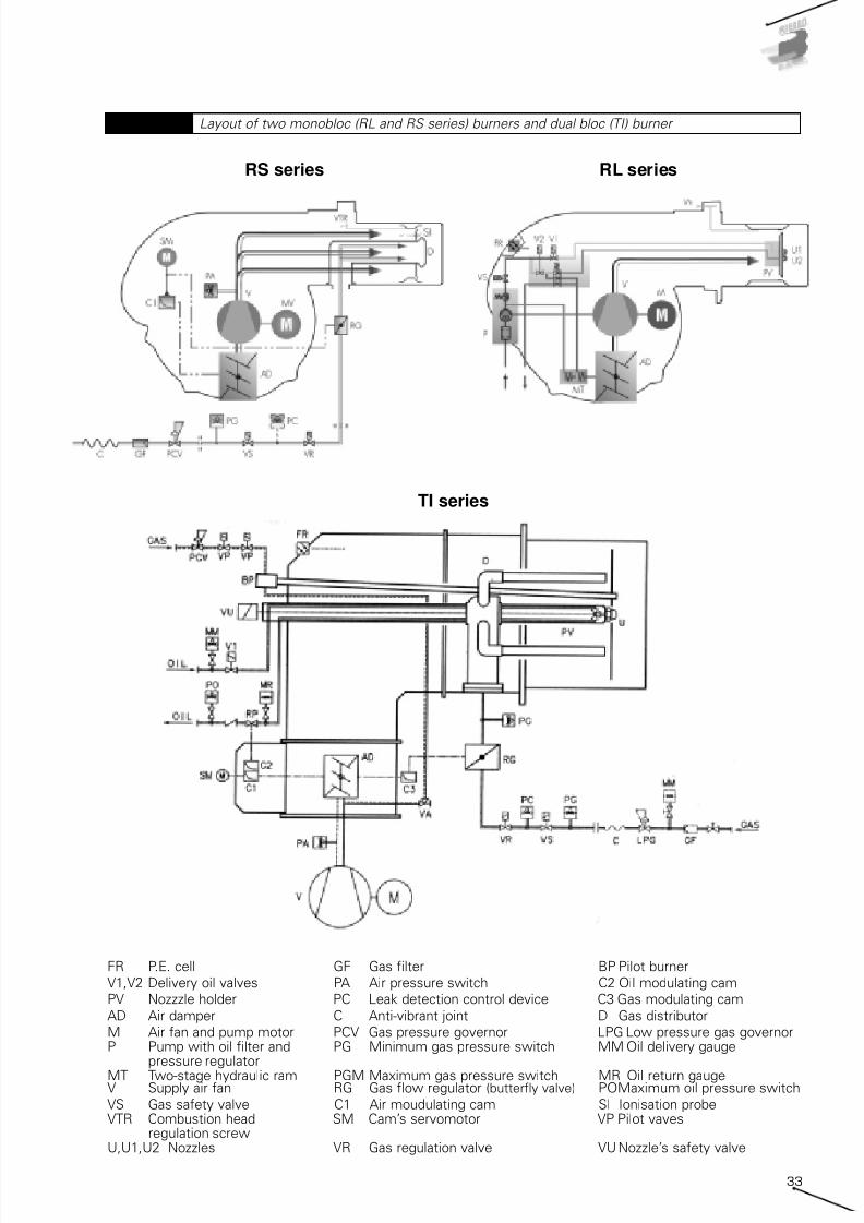
7/25/2019 Riello Burner Handbook
http://slidepdf.com/reader/full/riello-burner-handbook 32/16933
Layout of two monobloc (RL and RS series) burners and dual bloc (TI) burner Diagram 13
RS series
TI series
RL series
FR P.E. cell GF Gas filter BP Pilot burner
V1,V2 Delivery oil valves PA Air pressure switch C2 Oil modulating cam
PV Nozzzle holder PC Leak detection control device C3 Gas modulating cam
AD Air damper C Anti-vibrant joint D Gas distributor
M Air fan and pump motor PCV Gas pressure governor LPG Low pressure gas governorP Pump with oil filter and PG Minimum gas pressure switch MM Oil delivery gauge
pressure regulator
MT Two-stage hydraulic ram PGM Maximum gas pressure switch MR Oil return gaugeV Supply air fan RG Gas flow regulator (butterfly valve) POMaximum oil pressure switch
VS Gas safety valve C1 Air moudulating cam SI Ionisation probeVTR Combustion head SM Cam’s servomotor VP Pilot vaves
regulation screwU,U1,U2 Nozzles VR Gas regulation valve VU Nozzle’s safety valve

7/25/2019 Riello Burner Handbook
http://slidepdf.com/reader/full/riello-burner-handbook 33/16934
The burner should be chosen so that
maximum required load falls within the
burner's firing range. The firing point is found
by tracing a vertical line in correspondence
with the required output value and a horizontalline in correspondence with the pressure in
the combustion chamber; the intersection
point between the two lines is the system
firing point, including the burner and the heat
generator.
As far as the choice of single-stage burners is
concerned, the firing point can be in any point
of the burner's firing range.
For two-stage burners the firing range is ideally
divided into two areas, left (zone A) and right
(zone B) of the vertical line traced for the point
corresponding to the maximum head available,
as indicated in Diagram 16.
The firing point corresponding to the maximum
output and, consequently, to operate in the
2nd stage, must be chosen within zone B.
Zone B provides the maximum output of the
burner in relation to the combustion chamber
pressure.
The 1st stage output should be chosen within
the minimum/maximum declared formula and
normally falls within zone A. The absolute
lower limit corresponds to the minimum value
of zone A. However, in certain cases, for
example where the use of two-stage burners
is required in domestic hot water boilers, it is
advisable not to go below 60-65% of
maximum output in the first stage, and, due to
condensation problems, to maintain flue
temperature around 170-180°C at maximum
load and at 140°C at 65% of load.
As far as progressive or modulating two-stage
burners are concerned, the burner should be
chosen in a similar manner to two-stage
burners. In modulating burners, the nearer the
firing point is to the maximum output values of
the firing range, the higher the modulatingformula of the burner. The modulating formula
is defined as the turn down ratio between the
maximum output and the minimum output
expressed in proportion (e.g. 3:1 or 5:1).
0
1
2
3
4
5
6
7
50 100 150 200 250 300 350 400 450 500 550 600
kW
C o m b u s t i o n c h a m b e r p r e s s u r e ( m b
a r )
RLS 50RLS 38
RLS 28
Firing ranges of Riello RLS series
dual fuel burners Diagram 14
Test combustion chamber for burners Diagram 15
d = diameter of the flame tube Heat output (kW)
X L e
n g
h t o
f t h e
f l a m e
t u b e
( m )
F l a m
e t u b e
f i r i n g
i n t e n s
i t y ( k W / m 3 )

7/25/2019 Riello Burner Handbook
http://slidepdf.com/reader/full/riello-burner-handbook 34/16935
The firing range in cartesian format can only be
determined for monobloc forced draught
burners, where the coupling of the combustion
head with the fan is defined by the burnermanufacturer. The situation changes for dual
bloc burners, as the combination of the
combustion head and the fan is delegated to
the design engineer. In this case, the firing
range is characteristic only for the combustion
head and determined in relation to the
maximum and minimum fuel output allowed to
the head itself.
For example Diagram 17 shows the firing
ranges for combustion heads in the Riello TI
Series Burners, where the darker area
represents the range of optimum choice
recommended by the manufacturer.
The choice regarding the size of the
combustion heads should be made solely in
relation to the output and the temperature of
the combustion supporter air.
2.3 TYPICAL SYSTEM LAYOUT
DIAGRAMS
The burner is just one of the components of a
larger and more complex system for
generating heat. Before passing on to the
description of the individual parts of a
combustion system, the following pages show
the plant engineering diagrams for the various
types of fuel, regulation of the thermal loadand systems for optimising fuel control. By
overlapping the diagrams of each of these
layout classes, the entire combustion system
can be designed.
1000 2000 3000 4000 5000 6000 7000 8000 9000 10000 11000
0
0
kW0 2000 4000 6000 8000 10000 12000
Campo utile per la scelta del bruciatore Campo di modulazione
T e m p e r a t u r a a r i a
° C
Mcal/h
TI 14
TI 13
TI 12
TI 11
TI 10
50°C
150°C
50°C
150°C
50°C
150°C
50°C
150°C
50°C
150°C
Firing range of Riello RLS100- two
stage gas/light oil burner
Diagram 16
Firing range for Riello TI Series Burner combustion heads Diagram 17
Useful working field for choosing the burner Modulation range
A i r t e m p e r a t u r e ° C

7/25/2019 Riello Burner Handbook
http://slidepdf.com/reader/full/riello-burner-handbook 35/16936
2.3.2 System engineeringdiagrams for burners using lowviscosity (< 6 cSt) liquid fuels -diesel oil / kerosene
Gas supply - low pressure circuit Diagram 18
Gas supply - high pressure circuit Diagram 19
A = Drop-type plant with fedding
from top; B = air intake system
Diagram 20
Drop-type plant with feeding from
bottomDiagram 21
ServomotorBurner air fanAnti-vibrating jointGas filterGas governorMin gas pressure switchGas safety valveLeak proving systemGas regulation valveGas flow regulatorMax gas pressure switch
Air pressure switchServomotorBurner air damperBurner air fanAir pressure switchLight-oil tankLight oil filterBurner pumpNozzle holder lanceOil safety valve
ServomotorBurner air damper
Burner air fanAir pressure switchLight-oil tankLight oil filterBurner pumpNozzle holder lanceOil safety valve
ServomotorBurner air damperAnti-vibrating jointBurner air fanGas filterSecond stage gas reductionMin gas pressure switchGas safety valveLeak proving systemGas regulation valveGas flow regulatorMax gas pressure switchAir pressure switch
Ambient air
Ambient air
H
m a x
( g e n e r a l 1 0 m )
Ambient air
Ambient air
2.3.1 System engineeringdiagrams for gas fired burners
Gas pressure reduction Gas train
H
m a x
( g e n e r a l 1 0 m )

7/25/2019 Riello Burner Handbook
http://slidepdf.com/reader/full/riello-burner-handbook 36/16937
2.3.3 System engineering diagrams for burners using high viscosity (> 6cSt) liquid fuels
System with ring under pressure Diagram 22
Ring-type system for multi-stage and modulating burners with service tank Diagram 23
BR Dualbloc burnerBR1 Monoblock burnerB Gas separator bottler Oil filter 300 microns degreeMM Oil delivery gaugeP(MP) Pumping group – transfer ringP1(MP) Pumping group – burner circuit with filter
and pressure regulatorP2(MP) Pumping group – main circuit with filterPS Electr ical oi l preheaterRS1 Pump heater resistanceRS2 Oil tank heater resistanceSB Main oil tankSB2 Service oil tankT ThermometerTC Temperature switch regulation
ServomotorBurner air damperBurner air fanAir pressure switchLight-oil tankLight oil filterBurner pumpNozzle holder lanceOil safety valve
Light-oil ring pumpOil pressure gauge
Ambient air
Tr Flexible oil lineTr1 Flexible oil line pressure 25-30barTP Temperature probeTM Max oil pressure switchVC Vent valveVG Supply air fanVR1 Oil pressure regulator valve of
the oil burner ringVR2 Oil pressure regulator valve of the
oil main ringVS Preheater safety valveVG7 Safety valveVG Double valves
Heavy oil pipe with electricalpreheater cable
Two stage burner Modulating burner
Modulating burner

7/25/2019 Riello Burner Handbook
http://slidepdf.com/reader/full/riello-burner-handbook 37/16938
2.3.4 Diagrams for the calibration of single-stage burners
Ring-type system for multi-stage and modulating burners without service tank
Diagram 24
BR Dualbloc burnerBR1 Monoblock burnerB Oil burners gas separatorF Oil filter 300 microns degreeMM Oil delivery gaugeP(MP) Pumping group - main circuit with filterP1(MP) Pumping group - burner circuit with filter
and pressure regulatorPS Electrical oil preheaterRS1 Pump heater resistanceRS2 Oil tank heater resistanceSB Main oil tankT ThermometerTE Temperature switch regu lat ionTF Flexible oil line
TP Temperature probeTM Max o il temperature swi tchVC Control valve (3 way)VE Supply air fanVR1 Oil pressure regulator valve of
the oil burner ringVR2 Oil pressure regulator valve of the
oil main ringVS Preheater safety valveVGZ Safety valveVG Double valves
Heavy oil pipe withelectrical preheater cable
SER1 Burner air damperVT Burner air fanC Anti-vibrating jointGF Gas filterPCV Gas governorPG Min gas pressure switchVS Gas safety valvePC Leak proving systemVR Gas regu la tion valveRG Gas flow regu la torPGM Max gas pressure switch
T1 ThermostatQRP Burner control panelLA Nozzle holder lanceVS Oil safety valve
Layout of regulation components for a single-stage burner Diagram 25
Two stageburner
Modulatingburner
Modulating burner
Ambient air

7/25/2019 Riello Burner Handbook
http://slidepdf.com/reader/full/riello-burner-handbook 38/16939
2.3.5 Diagrams for the calibration of multi-stage burners
2.3.6 Diagrams for the calibration of modulating burners
Layout of regulation components for a two-stage burner Diagram 26
Layout of regulation components for a modulating burner Diagram 27
SMn ServomotorSER1 Burner air damperVT Burner air fanC Anti-vibrating jointGF Gas filterPCV Gas governorPG Min gas pressure switchVS Gas safety valvePC Leak prov ing sys temVR Gas regulat ion valve
RG Gas flow regulatorPGM Max gas pressure switchT1 Thermostato/Pressure switch
1st stageQRP Burner control panelLA Nozz le ho lder lanceVS Oil safety valveT2 Thermostato/Pressure
switch 2nd stage
SMn ServomotorSER1 Burner air damperVT Burner air fanC Anti-vibrating jointGF Gas filterPCV Gas governorPG Min gas pressure switchVS Gas safety valvePC Leak proving systemVR Gas regu la tion va lveRG Gas flow regu la torPGM Max gas pressure switchT1 Temperature / pressure probeQRP Burner control panelLA Nozzle holder lanceMD Modulat ion dev ice
Ambient air
Ambient air

7/25/2019 Riello Burner Handbook
http://slidepdf.com/reader/full/riello-burner-handbook 39/16940
2.3.7 Diagram of burner with measurement and regulation of thepercentage of O2 in the flue gases
2.3.8 Diagram of burner with pre-heating of the combustion supporterair
Layout of O 2 regulation systemDiagram 28
Layout of a system with pre-heating
of comburent air
Diagram 29
SMn ServomotorSER1 Burner air damperV1 Burner air fanQRP Burner control panelLA Nozzle holder lanceVS Oil safety valveEGA Exhaust gas analyzerFRV Fuel regulator valve (gas/oil)SO Exhaust gas probe
SC Exhaust gas/air heat exchangerVT FanVS Air damper
Ambient air
Ambient air
Fuel
pipe
Heavy oil

7/25/2019 Riello Burner Handbook
http://slidepdf.com/reader/full/riello-burner-handbook 40/16941
2.3.10 Layout of the Burner Management -System
Layout of the fan speed rotation regulation with inverter Diagram 30
Layout of integrated management for supervising a combustion systemDiagram 31
2.3.9 Diagram of burner with inverter controlled motors
SMn ServomotorSER1 Burner air damperV1 Burner air fanQRP Burner control panelLA Nozzle holder lanceVS Oil safety valveIV InverterFRV Fuel regulator valve (gas/oil)M Three phase induct ion motor
SMn Servomotor
SER1 Burner air damperV1 Burner air fanQRP Burner control panel
(i.e. micro modulation Autoflame)
LA Nozz le ho lder lance
VS Oil safety valveIV InverterFRV Fuel regulator valve (gas/oil)EGA Exhaust gas analyzer
SO Exhaust gas probe
DTI Data transfer interfaceLPC Local computerMDM ModemRPC Remote computer
Ambient air
Heavy oil
Heavy oil Heavy oil
Ambient air Ambient air

7/25/2019 Riello Burner Handbook
http://slidepdf.com/reader/full/riello-burner-handbook 41/16942
2.4 THE COMBUSTION HEAD
The combustion head is the part of the burner
that mixes the combustion supporting air with
the fuel and stabilises the flame that is
generated.The combustion head essentially comprises
the following components:
• The fuel metering device: nozzles for liquid
fuels and orifices and distributors for gaseous
fuels; oil nozzles are characterised by three
parameters: output, spray angle and type of
spray distribution (pattern).
• The turbulator diffuser disk, which mixes
the fuel and the combustion air, and stabilises
the flame to avoid it blowing back into the
burner;
• The flame ignition system, uses electric
arcs produced by high-voltage powered
electrodes directly igniting the flame or
coupled with a pilot burner;
• A flame sensor for motoring the flame;
• The flame tube comprising made ofprofiled metal cylinder which defines the
output speed range.
The flame tube and the diffuser disk
essentially determine the geometry of the
flame developed by the burner. Especially the
latter determines the rotational features of the
fuel and combustion supporter mixture flow
and, consequently, the flame dimensions. The
rotational characteristic of the mixture flow is
expressed in mathematical terms by the
number of swirls defined as:
S = Gf / (GxR)
where:
S = the number of swirls;
Gf = the angular momentum of the flow;
Gx = the axial force;
R = the radius of the nozzle outlet;
As a rule, an increase in the number of swirls
causes an increase in the flame diameter and
a decrease in the flame length.
Drawing of composition of combustion head for gas/light oil Riello RLS100 burner Diagram 33
FLAME TUBE
FLAME FIRINGELECTRODES
REGULATIONCYLINDER
GAS DISTRIBUTOR
SWIRLER DISK
DIFFUSER
OIL NOZZLELIQUID FUEL
SECONDARY AIRGAS NOZZLE
Nozzles: full cone and empty cone
distribution; definition of spray angle
Diagram 32

7/25/2019 Riello Burner Handbook
http://slidepdf.com/reader/full/riello-burner-handbook 42/16943
The section between the sleeve and the
diffuser disk determines the amount of
secondary air available for the flame. This
amount is zero when the disk is closer and in
contact with sleeve. In certain burners it is
possible to adjust the space between the diskand the turbulator diffuser changes the
secondary air by changing the position of the
disk itself.
Combustion heads can be classified according
to the following layout:
• Non-adjustable fixed head, where the
position of the combustion head is fixed by the
manufacturer and cannot be changed;
• Adjustable head, where the position of the
combustion head can be adjusted by the
burner installer during commissioning;• Variable-geometry head, where the
position of the combustion head can be varied
during the modulating burner operation.
Non-adjustable fixed head burners are
generally burners used for industrial processes
and dedicated to the generators they must be
coupled to.
For adjustable head burners, regulation is pre-
set in correspondence with the maximum
output of the burner for the specific
application. For easier start-up andconfiguration operations, a graph is provided
for each burner indicating the position of the
regulation mechanisms in relation to the
required thermal output. This construction
type makes the burner suitable for different
requirements, which is why monobloc Forced
draught burners with a low to medium output
are predominantly adjustable head types.
Variable-geometry burners are generally high-
output modulating burners.
The geometry of the head is also extremely
important in reducing polluting emissions,especially Nox, as described in paragraph
1.4.2.
2.4.1 Pressure drop air side
The firing ranges of monobloc burners already
take into account the air pressure drop of the
combustion head. When choosing a dual bloc
burner, for the purpose of choosing the correct
fan, the pressure drop on the air side must beknown in relation to the delivery; for easier
reading, this information refers to a standard
temperature and is supplied in relation to the
thermal output developed.
2.4.2 Pressure drop fuel side
To correctly select the fuel feed pipe for both
monobloc and dual bloc burners, certain
working information is required about the
related circuits inside the combustion head.
In the case of gaseous fuels, tables or
diagrams are provided, such as those
presented in diagram 35, which provide the
overall pressure drop of the gas pipe in thehead, in relation to the thermal output
developed.
For liquid fuels, the pressure value required by
the nozzle for spill back nozzles (modulating),
and the diagram of the minimum pressure to
be guaranteed on the nozzle return pipe when
the fuel delivery varies, are provided.
TI 10 head pressure drop side air referred to backpressure 0 - air damper notincluded
Air suction temperature 15°C
0
50
100
150
200
250
0 1 2 3 4 5
MW
S t a t i c P r e s s u r e [ m m w . c . ]
TI 10 P/NM
TI 10 P/M
Pressure drop air side in combustion
head - dualbloc TI 10 burner
Diagram 34
Natural gas G20 - Net calorific value 9,94 kcal/Nmc 0°C 1013 mbar
0
10
20
30
40
50
60
0 1000 2000 3000 4000 5000 6000 7000
Output Power (MW)
P r e s s u r e l o s s ( m b a r )
Pressure drop gas side in
combustion head - dualbloc TI 10 burner
Diagram 35

7/25/2019 Riello Burner Handbook
http://slidepdf.com/reader/full/riello-burner-handbook 43/16944
2.5 THE FAN
Fans are machines capable of supplying
energy to a fluid, by increasing pressure or
speed, using a rotating element.
Depending on the air-flow direction the
following types of fan can be used:
• centrifugal;
• axial;
• tangential.
In centrifugal fans, the air enters along the
direction of the rotation axis and exits
tangentially to the fan wheel. In axial fans, theair direction is parallel to the axis of the fan
wheel. In tangential fans, the air enters and
exists tangentially to the fan wheel.
The fans installed on monobloc burners and
those used separately for dual bloc burners are
generally centrifugal, such as that shown in
the Diagram.
Centrifugal fans are made up of a box that
contains a keyed fan wheel on a shaft
supported by bearings. The shaft can be
connected directly to the electric motor usingjoints or, indirectly, using belts and pulleys.
The fan wheel positioned inside the box may
have differing blade orientations/profiles and
specifically:
• fan wheel with wing-shaped blades;
• fan wheel with reverse curved blades,
• fan wheel with radial blades;
• fan wheel with forward curved blades;
Diagram 37 shows the variation in absorbed
output when fan delivery varies; the fan wheel
with wing-shaped blades behaves similarly tothe fan wheel with reverse curved blades.
The working characteristics of a fan, similar to
those for pumps, are described by the
characteristic curve. The characteristic curve
of a fan is represented in a Cartesian plan
where the Y axis shows the pressure and the
X axis shows the volumetric delivery (see
Diagram 38).
The characteristic curves can be accompanied
by other curves such as performance or yield
curves and the absorbed output curve of the
electric motor (see Diagram 39).
The number of characteristic curves for each
fan depends on the number of rotation speeds,
as shown in Diagram 40.
When a fan operates in a circuit, which also
Feed pressure of liquid fuel Diagram 36
Fan of a dualbloc burner Diagram 37
Output absorbed from different
types of fan varying delivery
Diagram 38
delivery (%)
curved forward blade
radial fan
axial fan
reverse curveblades
p o w e r a b s o r b e d ( % )
N o z z l e d e l i v e r y ( k g / h )
Return pressure (bar)

7/25/2019 Riello Burner Handbook
http://slidepdf.com/reader/full/riello-burner-handbook 44/16945
has a characteristic curve, delivery is supplied
when total pressure developed is equal to the
circuit pressure. This situation is represented
by the intersection point between the
characteristic fan curve and the characteristic
circuit curve, as indicated in Diagram 41.
In the case of forced draught burners, the
system characteristic curve varies in relation to
the setting of the combustion head and
opening degree of the air damper. To correctly
choose the fan, the circuit curve must
correspond to the load used.
Therefore, in order to discover the delivery and
the head of a fan, we need sufficiently precise
information regarding the pressure drop
induced by the circuit, including the air intake
pipes, burner head feeding pipes and the
accessories.
As already mentioned, circuit pressure drops
have a parabolic flow with respect to fluidspeed and, consequently, delivery.
Pressure drops in an areaulic system are
determined by two components:
• concentrated pressure drops;
• distributed pressure drops.
Among the concentrated pressure drops,
account must be taken of those introduced by
the combustion head, where the air transits
using a complex geometric route; furthermore,
an air damper is fitted inside the burner for
calibrating the delivery of combustionsupporter air.
Burner manufacturers provide graphs that
represent the trend of pressure drops in
relation to air delivery, or, for easier
consultation, in relation to the thermal output
delivered by the burner.
Distributed pressure drops can be estimated
by using the Darcy-Weisbach formula:
eq 2.5-1
where:
∆pf = pressure drop due to friction [m];
f = friction factor;
∆p f = .f .L
D
v2
2 . g
Typical performance graphs of a centrifugal fanDiagram 39
Fan performance graphs on varying
motor speed rotation
Diagram 40
Performance graph of fan and resistant circuit with working pointDiagram 41
1000 rpm
density 1,2 kg/m3
Lpa = Sound pressurelevel in dBA at 1,5 mdistance
Delivery
rpm
T o t a l p r e s s u r e
Discharge air velocity
d i n a m i c
p r e s s u
r e
L p a
Maximum fanpressure
Resistantcircuitperformancegraph
Fanperformancegraph
Nominal delivery
N o m i n a l p r e s s u r e
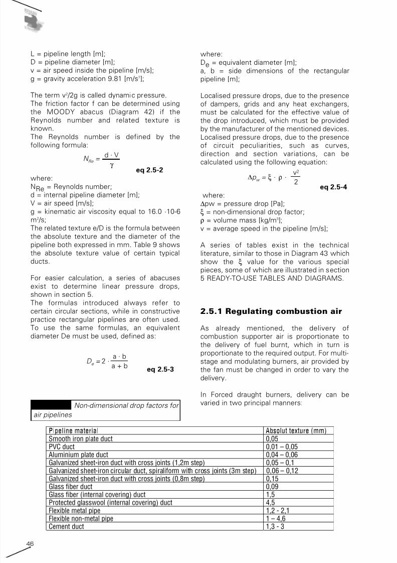
7/25/2019 Riello Burner Handbook
http://slidepdf.com/reader/full/riello-burner-handbook 45/16946
L = pipeline length [m];
D = pipeline diameter [m];
v = air speed inside the pipeline [m/s];
g = gravity acceleration 9.81 [m/s2];
The term v
2
/2g is called dynamic pressure.The friction factor f can be determined using
the MOODY abacus (Diagram 42) if the
Reynolds number and related texture is
known.
The Reynolds number is defined by the
following formula:
eq 2.5-2
where:
NRe = Reynolds number;
d = internal pipeline diameter [m];V = air speed [m/s];
g = kinematic air viscosity equal to 16.0 ·10-6
m2 /s;
The related texture e/D is the formula between
the absolute texture and the diameter of the
pipeline both expressed in mm. Table 9 shows
the absolute texture value of certain typical
ducts.
For easier calculation, a series of abacuses
exist to determine linear pressure drops,
shown in section 5.The formulas introduced always refer to
certain circular sections, while in constructive
practice rectangular pipelines are often used.
To use the same formulas, an equivalent
diameter De must be used, defined as:
eq 2.5-3D e = 2 . a . b
a + b
N Re =d . V
γ
where:
De = equivalent diameter [m];
a, b = side dimensions of the rectangular
pipeline [m];
Localised pressure drops, due to the presenceof dampers, grids and any heat exchangers,
must be calculated for the effective value of
the drop introduced, which must be provided
by the manufacturer of the mentioned devices.
Localised pressure drops, due to the presence
of circuit peculiarities, such as curves,
direction and section variations, can be
calculated using the following equation:
eq 2.5-4
where:∆pw = pressure drop [Pa];
ξ = non-dimensional drop factor;
ρ = volume mass [kg/m3];
v = average speed in the pipeline [m/s];
A series of tables exist in the technical
literature, similar to those in Diagram 43 which
show the ξ value for the various special
pieces, some of which are illustrated in section
5 READY-TO-USE TABLES AND DIAGRAMS.
2.5.1 Regulating combustion air
As already mentioned, the delivery of
combustion supporter air is proportionate to
the delivery of fuel burnt, which in turn is
proportionate to the required output. For multi-
stage and modulating burners, air provided by
the fan must be changed in order to vary the
delivery.
In Forced draught burners, delivery can bevaried in two principal manners:
∆p w =.ξ .ρ
v2
2
Pipeline material Absolut texture (mm)Smooth iron plate duct 0,05PVC duct 0,01 – 0,05Aluminium plate duct 0,04 – 0,06Galvanized sheet-iron duct with cross joints (1,2m step) 0,05 – 0,1Galvanized sheet-iron circular duct, spiraliform with cross joints (3m step) 0,06 – 0,12Galvanized sheet-iron duct with cross joints (0,8m step) 0,15Glass fiber duct 0,09
Glass fiber (internal covering) duct 1,5Protected glasswool (internal covering) duct 4,5Flexible metal pipe 1,2 - 2,1Flexible non-metal pipe 1 – 4,6Cement duct 1,3 - 3
Non-dimensional drop factors for
air pipelines
Table 9

7/25/2019 Riello Burner Handbook
http://slidepdf.com/reader/full/riello-burner-handbook 46/16947
• Varying the fan firing point;
• Varying the number of fan revolutions;
In the first regulation method, the fan firing
point is moved, which remember can only be
done along the characteristic curve, by varying
the pressure drop of the areaulic circuit byintroducing a servo-controlled damper (see
Diagram 44). Depending on the opening
degree of the damper, the various system
curves are obtained. In our case, the regulation
damper closing determines the variation of the
characteristic system curve from curve 1 to
curve 2; consequently, the fan firing point
moves from A to B, with the consequent
increase of the fan head from P1 to P2’ and
the decrease of the delivery from Q1 to Q2.
The opening degree of the damper introduces
the various characteristic system curves thusdetermining differing delivery values.
This system is rather effective, above all in
centrifugal fans with forward curved blades,
where a delivery drop corresponds to a drop in
absorbed output. In centrifugal fans with
reverse curved blades, the output curve has a
virtually flat trend and therefore it is not
possible to obtain optimum operating
performances.
The variation of the number of fan revolutions
is obtained by using specific electronic devices
called “inverters”.
These devices vary the frequency of the power
supply voltage to the electric motor connected
to the fan wheel. The number of electric motor
revolutions is linked to the power supply
frequency according to the following equation:
where:n = number of motor r.p.m.;
f = power supply voltage frequency [Hz];
p = number of poles;
By regulating the number of revolutions,
maximum performance operating can be
n = .120 f
p
Moody's abacus Diagram 42
Adimensional loss factors for air
pipelines
Diagram 43
f
Reynolds number Re = ρ Vd / µ
Transitionflow
L a m i n a r f l o
w
Turbolentflow

7/25/2019 Riello Burner Handbook
http://slidepdf.com/reader/full/riello-burner-handbook 47/16948
obtained under the various working conditions,
as the characteristic curve is translated until it
coincides with the nominal firing point.
Diagram 45 shows the fan behaviour when the
number of motor revs is varied.
branched (gas supply network). Inside the
pipelines, the gas is at a pressure, which is
variable by several tens of bars for main supply
pipelines, and by several tens of mbars in final
delivery pipelines of the gas to the user.
The main problem in distribution networks ofgaseous fuels is the variation in feed pressure.
Any pressure instability within the distribution
network causes the burner to work incorrectly.
In order to avoid such problems, fuel gas feed
pressure to the combustion head must be:
• Greater than a minimum value which can
overcome the pressure drop due to the
combustion head (see paragraph 2.4.2) and the
back pressure in the heat generator
combustion chamber;
• Lower than the permitted maximumpressure value declared by the manufacturer;
• Stable and repetitive with respect to the
settings.
To guarantee these conditions, fuel gas supply
to the burner is through a series of safety and
control equipment that globally are called the
“gas train”.
Diagram 45 shows the functional layout of a
gas train.
The connection module comprises a manualshut off valve and an anti-vibration connection
joint so that any vibrations produced by the
burner are not transmitted to the entire feed
network of the fuel gas.
The filter is used to guarantee filtration of any
particles that may be present in the gaseous
fuel, particles that might damage the seal of
the safety and shut off valve.
The task of the pressure reducer is to reduce
the pressure of the mains gas and maintain
constant the outgoing pressure, independently
from the incoming pressure and delivery.Pressure reduction and stabilising is made
through use of a membrane-type system
loaded by a spring that controls the shutter
opening using levers. The high pressure unit
includes the lock out, safety and discharge
valves as well as several gauges upstream and
downstream for visually controlling pressure
levels. The pressure reducer has a maximum
incoming pressure and a series of outgoing
Change of delivery by varying
pressure drops of the circuit
Diagram 44
Example of delivery changing by
motor speed variation
Diagram 45
Functional layout of the gas trainDiagram 46
Connectionmodulus
FilterPressurereducer
Pressurereducer
Safety anddeliveryvalves
BurnerGas pipeline
2.6 FUEL SUPPLY
2.6.1 Gas supply
Gaseous fuel is usually transported from the
point of storage/drawing to the user by a
series of pipelines, which may be more or less
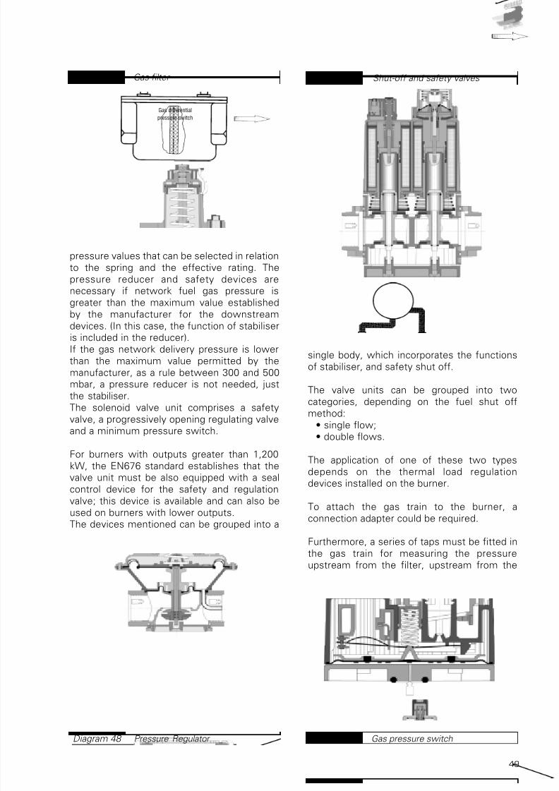
7/25/2019 Riello Burner Handbook
http://slidepdf.com/reader/full/riello-burner-handbook 48/16949
pressure values that can be selected in relation
to the spring and the effective rating. The
pressure reducer and safety devices arenecessary if network fuel gas pressure is
greater than the maximum value established
by the manufacturer for the downstream
devices. (In this case, the function of stabiliser
is included in the reducer).
If the gas network delivery pressure is lower
than the maximum value permitted by the
manufacturer, as a rule between 300 and 500
mbar, a pressure reducer is not needed, just
the stabiliser.
The solenoid valve unit comprises a safety
valve, a progressively opening regulating valveand a minimum pressure switch.
For burners with outputs greater than 1,200
kW, the EN676 standard establishes that the
valve unit must be also equipped with a seal
control device for the safety and regulation
valve; this device is available and can also be
used on burners with lower outputs.
The devices mentioned can be grouped into a
single body, which incorporates the functions
of stabiliser, and safety shut off.
The valve units can be grouped into two
categories, depending on the fuel shut off
method:• single flow;
• double flows.
The application of one of these two types
depends on the thermal load regulation
devices installed on the burner.
To attach the gas train to the burner, a
connection adapter could be required.
Furthermore, a series of taps must be fitted in
the gas train for measuring the pressureupstream from the filter, upstream from the
Gas filter Diagram 47
Pressure Regulator Diagram 48
Gas differential
pressure switch
Shut-off and safety valves Diagram 49
Gas pressure switchDiagram 50

7/25/2019 Riello Burner Handbook
http://slidepdf.com/reader/full/riello-burner-handbook 49/16950
valve unit and in correspondence with the
combustion head.
As already said, if the pressure upstream from
the manual shut off valve is lower than a
certain value established by the manufacturer,
the pressure reducer is not required. In thiscase, the gas train supplied with the burner
can be monobloc, i.e. with the filter, stabiliser
and valve unit included inside a single
component or else comprising individual
components joined in series.
For domestic uses where the EEC 90/396 Gas
Directive makes it compulsory for the
manufacturer to type approve the whole system
including the burners and the feed system, the
complete gas train must be provided by the
manufacturer and type approved together with
the rest of the devices.The choice of the gas train depends on the
minimum pressure to be guaranteed to the
burner head and, consequently, the maximum
pressure drop determined by the latter, as
illustrated in the subsequent paragraph and in
the example in section 3.
A series of components are fitted to the
burner, which have a very important role during
setting and regulating the entire system. In
particular, gas or dual fuel burners have a
butterfly valve to regulate fuel delivery, driven
by a variable profile mechanical cam
servomotor, or in the more sophisticatedsystems, controlled by the Burner
management system (electronic cam).
Generally, there is a maximum gas pressure
switch to shut off burner functions if pressure
is too high along the fuel supply line.
2.6.1.1 Calculating the fuel gas supply
pipelines
The following formula is used for dimensioningthe fuel gas supply pipelines:
Eq. 2.6.1-1
where:
∆PA-B = pressure drop between point A and
point B [Pa];
l = friction factor;
V = the average gas speed [m/s];
r = the gas volume mass [kg/m3] referring to15°C and 1,013 mbar;
LTOT = total pipeline length [m];
Di = internal pipeline diameter [m];
The average gas speed inside the pipeline can
be calculated using the following formula:
Eq. 2.6.1-2
where:
Q = fuel gas delivery [m3 /h];
Di = internal pipeline diameter [m];
The fuel gas delivery must be established
using the following formula:
Eq. 2.6.1-3
where:
Q = fuel gas delivery [m3 /h];
m = maximum burner output [kW];
Hi = inferior calorific value of the fuel gas
[kWh/m3];Remember that 1 kWh = 3,600 kJ.
The friction factor λ can be calculated using
the following formula:
Q =m
H i
V =Q
A= [m/s]
Q
2827. Di2
∆P A-B =. LTOT
λ . V2 . ρ2 . Di
Seal control systemDiagram 51
Connection adaptor Diagram 52
ø2
ø1

7/25/2019 Riello Burner Handbook
http://slidepdf.com/reader/full/riello-burner-handbook 50/16951
Eq. 2.6.1-4
where:
Di = internal pipeline diameter [m];Re = the Reynolds number which can be
determined by using the following equation:
Eq. 2.6.1-5
where:
Di = internal pipeline diameter of the [m];
g = fuel gas kinematic viscosity [m2 /s];
Q = fuel gas delivery [m3 /h];
The viscosity of the gaseous fuel can be takenfrom the graph illustrated in diagram 53.
The graph shows the absolute viscosity
expressed in micropoises. Remember that the
kinematic viscosity is linked to the dynamic
viscosity by the formula:
Eq. 2.6.1-6
where:
γ absolute= dynamic or absolute viscosity
[kg/m·s];
γ = fuel gas kinematic viscosity [m2 /s];ρ = the volume mass of the gas [kg/m3]
referring to 15°C and 1,013 mbar;
In technical practice, the absolute viscosity is
measured in Poises (P) equating to:
γ absolute =γ ρ
Re = .354 Q
Di . γ
. 10-6
λ = +0,0072 +2,9 . 10-5 . Re
0,109
Di
0,612
Re0,35
The pressure drops in feed pipelines between
the fuel gas delivery point and the burner gastrain must be kept within limits that guarantee
correct functioning of any reducer units
present. For low pressure systems (p ≤ 40
mbar), the pressure drops must be kept within
the following values:
The pressure drops in the pipelines are the
sum of those distributed along the pipeline and
those concentrated due to joints and hydraulic
accessories (filters, valves, etc..).The concentrated losses due to hydraulic
accessories are calculated using the equivalent
length method, in other words a concentrated
loss is assimilated to a stretch of pipeline
equal to the length of the related loss.
To correctly dimension the pipelines, we can
define the following sizes:
LEFF = effective pipeline length [m];
LEQUIV = the sum of the equivalent lengths
relating to concentrated pressure drops as a
result of joints and hydraulic accessories[m];
LTOT = total pipeline length, sum of theeffective length and the equivalent length [m]:
LTOT = LEFF + LEQUIV Eq. 2.6.1-7
The equivalents lengths relating to the
concentrated resistances of the components
can be determined using the schedule shown
in Table 11, which shows the reference
equivalent lengths of the main concentrated
resistances.
To determine the equivalent length, we mustpresume an initial pipeline diameter imposing
a maximum fuel gas flow speed of
approximately 1 m/s, taking care to correct the
value of the equivalent lengths if a different
1poise = 1 =Kg
m . s
g
cm . s0,1
Absolute viscosity of certain gases Diagram 53
°C
P a s x 1 0 6
Maximum pressure drops of gas
pipelines
Table 10
Gas
Town gasNatural gas and air mixtures
Natural gasNatural gas replacementsL.P.G. and air mixtures
Liquid Petroleum Gas (G.P.L.)
Pressure drop
[mbar]
0,5
1,0
2,0
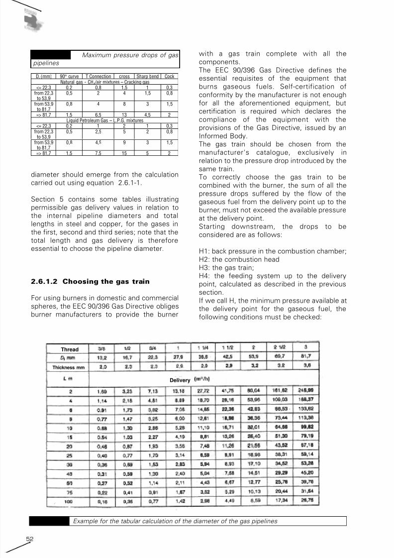
7/25/2019 Riello Burner Handbook
http://slidepdf.com/reader/full/riello-burner-handbook 51/16952
diameter should emerge from the calculation
carried out using equation 2.6.1-1.
Section 5 contains some tables illustrating
permissible gas delivery values in relation to
the internal pipeline diameters and total
lengths in steel and copper, for the gases in
the first, second and third series; note that the
total length and gas delivery is therefore
essential to choose the pipeline diameter.
2.6.1.2 Choosing the gas train
For using burners in domestic and commercial
spheres, the EEC 90/396 Gas Directive obliges
burner manufacturers to provide the burner
with a gas train complete with all the
components.
The EEC 90/396 Gas Directive defines the
essential requisites of the equipment that
burns gaseous fuels. Self-certification of
conformity by the manufacturer is not enoughfor all the aforementioned equipment, but
certification is required which declares the
compliance of the equipment with the
provisions of the Gas Directive, issued by an
Informed Body.
The gas train should be chosen from the
manufacturer's catalogue, exclusively in
relation to the pressure drop introduced by the
same train.
To correctly choose the gas train to be
combined with the burner, the sum of all the
pressure drops suffered by the flow of thegaseous fuel from the delivery point up to the
burner, must not exceed the available pressure
at the delivery point.
Starting downstream, the drops to be
considered are as follows:
H1: back pressure in the combustion chamber;
H2: the combustion head
H3: the gas train;
H4: the feeding system up to the delivery
point, calculated as described in the previous
section.If we call H, the minimum pressure available at
the delivery point for the gaseous fuel, the
following conditions must be checked:
Di (mm) 90° curve T Connection cross Sharp bend CockNatural gas - CH4 /air mixtures – Cracking gas
<= 22,3 0,2 0,8 1,5 1 0,3from 22,3
to 53,9
0,5 2 4 1,5 0,8
from 53,9to 81,7
0,8 4 8 3 1,5
=> 81,7 1,5 6,5 13 4,5 2Liquid Petroleum Gas – L.P.G. mixtures
<= 22,3 0,2 1 2 1 0,3from 22,3
to 53,90,5 2,5 5 2 0,8
from 53,9to 81,7
0,8 4,5 9 3 1,5
=> 81,7 1,5 7,5 15 5 2
Maximum pressure drops of gas
pipelines
Table 11
Example for the tabular calculation of the diameter of the gas pipelines Table 12
Thread
Thickness mm
Delivery

7/25/2019 Riello Burner Handbook
http://slidepdf.com/reader/full/riello-burner-handbook 52/16953
H ≥ H1 + H2 + H3 + H4
For ease of calculation, certain manufacturers
provide diagrams of the pressure drops in the
gas trains as the sum of the gas train pressure
drop and the combustion head (H2+H3).Therefore, the choice of gas train must be
satisfy the following equation:
Noting the maximum allowable value of
H2+H3, using diagrams similar to those in
Diagram 47, we can choose the gas train.
As shown in the diagram, the graph of the gas
train characteristic curve is often accompanied
by a graph showing the burner firing range tofacilitate the choice.
2.6.1.3 The feeding of liquid petroleum
gases (LPG)
Liquid petroleum gases are gases in a liquid
state obtained by distilling crude oil or taken
from natural gas and residual gases from
refinery process. The composition of LPG is
somewhat variable but generally comprisesmixtures of propane and butane, which are
generally considered fuels with a high level of
purity.
LPG is produced and conserved in a liquid
state, for storage and transporting large
amounts in an economically viable manner.
The volume formula between the gaseous
stage and the liquid stage is variable and
generally equates to 250 Nm3 /m3; this means
that during the transition from the gaseous
state to the liquid state the mixture reduces itsvolume by over 250 times, so that even with
tanks of limited dimensions it is possible to
store considerable amounts of the fuel.
Therefore, to obtain a cubic metre of LPG in
gaseous state, 4 litres of LPG in liquid state are
needed.
The vapour tension of LPG is low making it
possible to liquefy the gas with a pressure
around 3 ÷ 5 bars. LPG can be distributed to an
individual user or to a series of users. In the
first case, the individual user can be
guaranteed a sufficient stock of fuel using aseries of cylinders weighing several tens of
kilograms connected in series or by small
tanks usually with a capacity of less than 5 m3.
In the second case, a medium or low pressure
distribution network linked to a single large
0
24
6
8
10
12
14
16
18
20
22
24
26
28
30
32
34
36
38
40
460 480 500 520 540 560 580 600 620 640 660 680 700 720 740 760 780 800 820
Output (kW)
P r e s s u r e l o s s ( m b a r )
Combustion head MB 15/2 + combustion head MB 20/2 + combustion head
Graph for the detrmination of the gas trainDiagram 55
LPG tank Diagram 54

7/25/2019 Riello Burner Handbook
http://slidepdf.com/reader/full/riello-burner-handbook 53/16954
storage tank guarantees the supply to the
individual user. The first solution is adopted to
guarantee the gas supply to individual isolated
users or those who have particular
requirements, while the adoption of a
distribution network is convenient for smallcommunities or populated areas. With respect
to the use of individual cylinders, installed in
private property, the centralised system offers
considerable advantages in terms of safety
and continuity of running.
The LPG contained in a tank comprises a liquid
state in the lower part and a gaseous state in
the upper part. The tank cannot be filled
completely in the liquid state, because should
the temperature rise, the liquid, which cannot
be compressed and is under pressure, wouldnot be able to expand, with the consequent
danger of the tank exploding. Therefore, a
portion of volume free from the liquid state
must be guaranteed, equal to at least 20% of
the total volume.
LPG is used in burners and other equipment
nearly always when the fuel is in a gaseous
state.
LPG can be bled from the tank directly in its
gaseous state from the top of the tank or can
be drawn off in the liquid state from the
bottom of the tank to then be transformed intogas in a special vaporiser.
When drawing off in the gaseous state, the
delivery from the top of the tank causes a
pressure drop inside the tank, thus modifying
the balance between the liquid and the
gaseous state, causing part of the liquid to
evaporate in order to restore the initial
pressure. LPG evaporation is an exothermic
transformation, in other words it takes place
by absorbing heat, subtracting it from the
liquid mass of the LPG. The cooling of the
liquid mass is proportionate to the amount ofLPG drawn off in the gaseous state and
determines a further pressure drop in the tank.
If it is drawn off at a constant speed and within
a certain limit, a balance will be established in
which the heat required for transforming the
state of the LPG is guaranteed by the heat
exchange with the surrounding environment. It
must be remembered that the heat exchange
between the tank and the surrounding
environment takes place exclusively through
the portion of the external surface dampened
by the liquid LPG.If the gas is drawn off at a speed greater than
the limit allowed, the temperature of the tank
will fall considerably to the extent that a layer
of ice forms on the surface of the tank, further
decreasing the heat exchange with the
surrounding environment until the fuel
transformation is blocked, making drawing off
impossible.
From the description of the process, we can
see that the amount of gas that can bedelivered from the tank depends on the heat
transmission characteristics between the tank
and the environment, which depend on the
form, material and colour of the tank, as well
as on the environmental conditions where the
tank is installed. The tank manufacturers
provide the maximum delivery capacity for the
tank under standard working conditions,
usually expressed in kg/h. This capacity may
vary from 0.5 kg/h for small cylinders up to
nearly 20 kg/h for tanks with a capacity of 5 m3.
We should also remember that the deliverycapacity of a tank depends on the filling level,
decreasing as the fuel level decreases, due to
the decrease in pressure and the heat
exchange surface area. This means that not all
the contents of the tank can be used, in order
to guarantee a sufficient feed pressure. This
minimum filling level, after which it should be
topped up, is established by the tank
manufacturer and is equal to around 25% of
the tank's volume.
Therefore, the portion of the tank's volume
that can be effectively used is equal toapproximately 55% of the geometric volume
of the tank.
To calculate the thermal capacity stored, we
can use the following equations:
Es = 0,55 · VG · d · PCILPG
Where:
ES = energy stored by the tank [MJ];
VG = the geometric volume of the tank [m3];
d = LPG density equal to 0.52 kg/l [kg/l];PCILPG = inferior calorific value of the LPG
and equal to approximately 46 MJ/kg [MJ/kg];
The number of estimated annual refills is:
n = ES / EUwhere:
n = number of annual refills;
ES = energy stored by the tank [MJ];
EU = energy consumed by the users [MJ];
Furthermore, we must always check that the
total output installed does not exceed themaximum delivery capacity of the tank, in
particular:
mtank > musers = PU / PCILPG

7/25/2019 Riello Burner Handbook
http://slidepdf.com/reader/full/riello-burner-handbook 54/16955
where:
mtank= maximum delivery capacity of the tank
[kg/h];
musers = maximum fuel delivery required by
the users [kg/h];
PU = output installed by the users [kW];PCILPG = inferior calorific value of the LPG
and equal to approximately 12.78 kWh/kg
[kWh/kg]
When the delivery requested by the users
exceeds the maximum delivery capacity of the
available tanks, it must be drawn of in the
liquid state. It is drawn off from the bottom of
the tank with the fuel in a liquid state, and then
cause the liquid to vaporise using a heat
exchanger (vaporiser). This system guarantees
the complete vaporisation of the LPG andpermits the eventual pre-heating of the latter
to avoid the formation of condensation on the
pipeline. It is usually used where the cost of
vaporisation is justified by the complexity of
the system and is virtually compulsory if, for
reasons of safety and space, the tanks are
underground, as in this case the heat
exchange between the tank and the outside
environment is poor.
The pressure reduction from that inside the
storage tank, (generally around 5 bars), to theworking pressure (e.g. for small users around
30 mbars), is usually by a double-stage
system. The first reducer reduces the pressure
to 1.5 bars, while the second reducer reduces
the pressure to 30 mbar (150 mbar for
supplying industrial burners).
LPG in the gaseous form has a density more
than 50% higher than that of air, and therefore
in case of accidental leakage it tends to stratify
low down and stagnate in pockets on the floor.
In order to expel it, aeration is not always
enough but the physical removal usingappropriate means is often required. Any
detectors and permanent aeration vents
should be positioned flush with the floor.
2.6.2 Feeding diesel oil andkerosene
Hydraulic circuits on board liquid fuel burners
or mixed burners, have different features and
complexity, depending on the type of fuel,supplied output, load regulation logic (single-
stage, multi-stage or modulating) and special
standards in force. Generally the burners are
fitted with a geared pump and a single or
double fuel shut off solenoid system.
Modulating burners also have shut off valves
on the return circuit and a pressure regulator
for varying output.
The fan motor drives the pump, or it is run
independently, it can have special features for
using kerosene. The following diagram shows
the section of a typical geared pump fitted to
the RL 190/M model, for example, on
monobloc diesel oil burners (RL series).
In modulating burners, the modulating
pressure regulator is activated in combination
with the air damper, using mechanical lever
systems or electronic systems that point by
point supply fuel and combustion air in the
correct proportions to obtain the required
output.
For adaptation to specific standards, pressurecontrol devices can be fitted, such as
minimum and maximum oil pressure switches.
The table below shows the commercial
Shut-off solenoid valve on output
circuit - close postition
Diagram 56
Gear pump for liquid fule monobloc
burner
Diagram 57
Suction
Return
To the nozzle

7/25/2019 Riello Burner Handbook
http://slidepdf.com/reader/full/riello-burner-handbook 55/16956
wording for the various liquid fuels,
highlighting the typical plant engineering types
for diesel oil and kerosene.
The diesel oil feed systems covered in this
section are a "bi-pipeline" type and namely
those comprising a delivery pipeline from the
tank to the burners and a return pipeline from
the burner to the tank.
Systems also exist with single diesel oil
feeding pipelines, without a return line to the
storage tank, where re-circulation of the
unburned diesel oil takes place in proximity to
the burner itself using specific accessory
components.
By varying the tank position with respect to
the burner position, we have the following
plant engineering examples:
1. drop-type systems with supply from
bottom;
2. drop-type systems with supply from
summit;
3. in-take type systems;
4. systems with ring under pressure.
The first three plant engineering types do not
require the use of an additional pump, butentrust diesel oil circulation to the pump
installed on the burner.
In the system with the ring under pressure, an
additional pump is required with the task of
guaranteeing the fuel flow in the main ring.
Due to the long distance between storage tank
and burner, the burner pump normally has to
guarantee the feed pressure.
The minimum temperature that diesel oil can
reach in underground or insulated pipelines,
can be assumed as +2°C.
The first three plant engineering types are
discussed together as they are subject to the
same criticality.
2.6.2.1 Drop-type system with supply
from bottom / drop-type system with
supply from summit / intake type
system
As already mentioned, these three plantengineering types are related by the fact that
the burner pump must guarantee fuel
transport from the storage tank to the burner
nozzles.
Viscosity
- +I Kerosene Gasolio Olio
combustibile fluido
Olio
combustibilesemidenso
Olio
combustibiledenso
Catrami
UK kerosene Gas oil Light fueloil
Medium fueloil
Heavy fueloil
Tars
D Heizol EL Heizol M Heizol S Heizol S
F kerosene Domestique Lourd n°1 Lourd n°2 Bitume
USA 6
Air intake
system
yes yes no no no
Drop-typesystem
yes yes yes(unwary)
no no
Ring under
pressure
yes yes yes yes yes
Pipelines
heating
no no optional advised yes
I n c om b u s t i b
l e
N a m e
F e e
d i n g c i r c u i t
Light oil burner feeding Diagram 58
Summary of liquid fuels Table 13
Teer

7/25/2019 Riello Burner Handbook
http://slidepdf.com/reader/full/riello-burner-handbook 56/16957
In drop-type systems with supply from the
bottom (Diagram 21) the difference in height
between the maximum level reachable in the
storage tank and the centre of gravity of the
pump must be lower than the value
established by the burner manufacturer(generally between 4 and 10 meters) so as not
to over-stress the pump seal mechanism.
For drop-type systems with supply from the
summit (Diagram 20A), it is advisable that the
height P, vertical distance between the centre
of gravity of the burner pump and the highest
point in the circuit, does not exceed a certain
value established by the burner manufacturer
(generally between 4 and 10 meters) so as not
to over-stress the pump seal mechanism.
Furthermore, to allow self-priming the pump,
the height V must be no greater than 4meters.
In the intake-type system (Diagram 20B), a
pump depression of 50,000 Pa (0.50 bar) must
not be exceeded, so that gas is not released
from the fuel, sending the pump into
cavitation.
These pipelines can be dimensioned using the
ready-to-use tables supplied by the burner
manufacturer, where on the basis of the plant
engineering type, the difference in height
between the intake mouth and the pump's
centre of gravity, and the pipeline diameter,the maximum realisable distance from the
system is provided.
This distance should be taken as the total
length of the delivery pipeline. One of these
tables is presented below by way of example:
If we require an analytical calculation of the
pipelines, we can use the procedure indicated
in the following paragraph for systems with
pressurised ring.
Whatever the plant engineering type chosen, a
diesel oil filter must be fitted on the delivery
pipeline for separating water and impurities
present in the fuel, and a standard valve at the
end of the delivery pipeline in the fuel storage
tank.The diesel oil storage tank must also be
equipped with all the devices required by
current local legislation (breather pipes, shut
off valves, etc..).
2.6.2.2 Systems with pressurised ring
If the burner pump cannot self-feed because
the distance and/or the difference in height of
the tank are greater than the values suppliedby the burner manufacturer, a pressurised ring
circuit must be adopted.
The ring-type circuit comprises a pipeline,
which departs from and returns to the storage
tank, with an auxiliary pump to make the fuel
flow under pressure.
Pumping unit P (main ring)
This pumping unit must have a delivery equal
to at least twice the sum of the maximum
drawing capacities of the burners and
comprise a couple of pumps and filters withthe possibility of switchover in by-pass:
Qp2 = 2 · (∑Mi) eq 2.6.2-1
where Mi is the pump delivery of the individual
burner.
This over-dimensioning is necessary to
guarantee stable pressure in the ring
independently from the possible burner
functioning combinations.
This pumping unit must have a line filter with a
metal net cartridge for diesel oil, to separatethe impurities and water that may be present
in the fuel.
The pumping unit head should be calculated on
the basis of the residual pressure which must
be guaranteed to the ring and the pipeline
pressure drops calculated as specified below.
In the absence of certain information from the
burner manufacturer concerning the pump
delivery on the machine, the following typical
values can be used:
• for multi-stage burners: M = 1.3÷1.5 ·m• for modulating burners: M = 2.0÷2.5 ·m
where m is the delivery of fuel equivalent to
the maximum output of the burner.
Schedule for the tabular scaling of
the light oil feed pipelines
Table 14
Pipeline length (m)

7/25/2019 Riello Burner Handbook
http://slidepdf.com/reader/full/riello-burner-handbook 57/16958
Pipelines
The pipelines are dimensioned considering the
flow inside the pipes under turbulent
conditions, as diesel oil has low viscosity.
The pipeline pressure drops are the sum of
those distributed along the pipeline and thoseconcentrated due to connecting elements and
hydraulic accessories (filters, valves, etc..).
The concentrated drops due to hydraulic
accessories are reckoned using the equivalent
lengths method, i.e. a concentrated loss is
assimilated to a section of pipeline equivalent
to the length of the related loss.
To correctly dimension the pipelines the
following sizes are defined:
LEFF = effective length of the pipeline [m];
LEQUIV = sum of equivalent lengths relative to
concentrated pressure drops as a result ofconnecting elements and hydraulic
accessories [m];
LTOT = total length of the pipeline, sum of the
effective and equivalent lengths [m]:
LTOT = LEFF + LEQUIV [m] Eq 2.6.2 -2
The equivalent lengths relative to the
concentrated resistances of the components
must be taken from the technical
specifications supplied by the manufacturer. If
these values are not available, some tablesexist, shown in section 5, which contain the
equivalent lengths referring to the main
concentrated resistances.
Any filters must be calculated using the
effective pressure drop procured by their
presence provided by the manufacturer. If the
exact pressure drop value is not available, the
filter can be assimilated to an open valve.
The calculation delivery is, obviously, equal to
that of the pumping unit on the main ring.
As far as the delivery pipeline is concerned,the diameter should be chosen in relation to
the maximum permitted speed equating to
1÷2 m/s using the following equation:
eq 2.6.2 -3
where:
d = internal pipeline diameter [m];
Q = delivery in terms of liquid fuel volume[m3 /s] equal to m/ ρ where ρ is the diesel oil
volume mass as calculated below and m is the
delivery in terms of diesel oil mass;
V = liquid fuel flow speed equal to 1.5 m/s;
A = π . = d⇒ √Q
V
d2
4
4 . Q
π . V⇒
Q
V=
The chosen pipeline corresponds to the
commercially available diameter immediately
above that determined using the equation
2.6.2-3.
After establishing the pipeline diameter, the
exact fluid speed inside the pipeline must becalculated using the equation 2.6.2-3 to
establish the effective hydraulic status of the
system, calculating the Reynolds Number
using the following formula:
Eq 2.6.2 -4
where:
NRe = Reynolds Number;
d = internal pipeline diameter [m];
V = liquid fuel flow speed;
γ = kinematic viscosity at the transfertemperature of the liquid fuel [m2 /s];
If NRe > 2,320, the flow is defined as
turbulent; otherwise we have a laminar flow.
The intake pipeline, i.e. the length upstream
from the pump, between the pump itself and
the storage tank, must be dimensioned in
relation to the maximum permissible project-
related drop.
The maximum project-related pressure drop is
equal to:
∆P prog = ∆P amn - ∆hasp - ∆P acc [Pa]
Eq 2.6.2 -5
where:
∆P amn= the absolute pressure allowed at
intake (NPSH) indicated by the pump
manufacturer; otherwise, this pressure must
not be less than 50,660 Pa (0.5 bar);
∆hasp = intake height [Pa];
∆P acc = head loss due to the presence ofhydraulic accessories not calculated in
determining the equivalent lengths on the
intake pipeline (filters, etc..) [Pa]
The intake height is equal to:
∆hasp = ∆hgeom. ρ . 9,81 [Pa] eq 2.6.2 -6
where:
∆hgeom = the difference in height between the
fuel test point in the tank and the centre of the
delivery pump [m];
ρ = diesel oil volume mass [kg/m3];The value of ∆hgeom is positive if the tank test
point is lower than the centre of the pump,
negative if the tank test point is higher than
the centre of the pump.
N Re =d . V
γ

7/25/2019 Riello Burner Handbook
http://slidepdf.com/reader/full/riello-burner-handbook 58/16959
The liquid fuel volume mass depends on the
temperature according to the following
formula:
eq 2.6.2 -7
where:
ρ = liquid fuel volume mass [kg/m3];
ρ 15 = liquid fuel volume mass at the reference
temperature of 15°C equal to 865 kg/m3;
t = transfer temperature of the diesel oil equal
to 2°C [°C];
β = expansion formula equal to 0.00064°C-1;
If the flow is laminar, the pipelines should be
dimensioned according to the following
formula:
eq 2.6.2 -8
where:
d = internal pipeline diameter [m];
γ = kinematic viscosity of the liquid fuel
transfer temperature [m2 /s];
LTOT = total pipeline length, sum of the
effective and equivalent lengths [m];
m = mass-related delivery of the pumping unit
[kg/s];∆Pprog = maximum project-related pressure
drop (depression) [Pa];
In technical practice the kinematic viscosity is
expressed either in cSt or in a unit of measure
depending on the type of viscometer used to
measure the viscosity (Engler, Saybolt
universal, Redwood degrees, etc…); therefore,
before using the previous formula the
d = 42 . γ . LTOT .m
∆Pprog√
ρ =ρ
15
1 + β . (t - 15)
kinematic viscosity must be transformed into
cSt using the tables and alignment charts
indicated in section 5, remembering that:
1 cSt = 1 mm2 /s = 10 -6 m2 /s; eq. 2.6.2 -9
If the flow is turbulent, the pipelines should be
dimensioned according to the following
formula:
where:
d = internal pipeline diameter [m];
γ = the friction factor to be estimated in the
diagram shown below in relation to the NRe
and the relative texture e/D, where erepresents the absolute texture in mm;
LTOT = the total pipeline length, sum of the
effective and equivalent lengths [m];
m = mass-related delivery of the pumping unit
[kg/s];
∆Pprog = maximum project-related pressure
drop (depression) [Pa];
The table 15 shows the value of the absolute
texture of certain types of pipelines:
The graph 59 shows the friction factor value f in relation to the Reynolds Number NRe and
the relative texture e/D.
The diameter calculated in this manner must
not, in any case, be less than 6 mm.
Once the above-mentioned diameter has been
calculated, it is necessary to check that the
speed is not lower than 0.15 m/s using the
equation (2.6.2-3), specifically:
d = 0,00084 .√5 γ . LTOT .m
2
∆Pprog
Material Wall status Absolute texture (mm)
Wire-drawing pipes, new
(copper, brass, bronze, light alloy)
Synthetic material pipes, new
technically smooth 0,001 3 ÷ 0,001 5
rolled film 0,02 ÷ 0,06
pickled 0,03 ÷ 0,04Non-welded pipes, new
zinc-plated 0,07 ÷ 0,16
rolled film 0,04 ÷ 0,1
tarred 0,01 ÷ 0,05Longitudinal welded pipes, new
galvanized 0,008
moderately rusted or lightly
encrusted0,15 ÷ 0,2
Stell pipes after long employ
heavily encrusted up to 3
Absolute texture of the pipelines Table 15
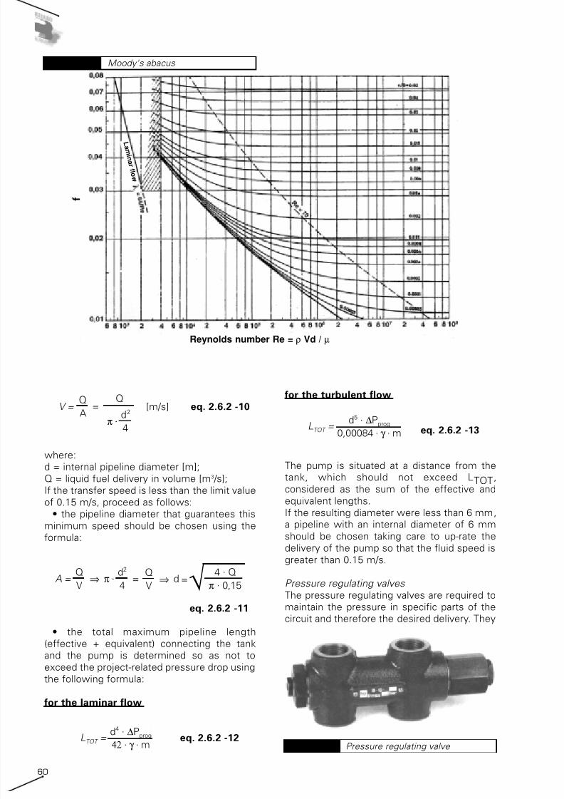
7/25/2019 Riello Burner Handbook
http://slidepdf.com/reader/full/riello-burner-handbook 59/169

7/25/2019 Riello Burner Handbook
http://slidepdf.com/reader/full/riello-burner-handbook 60/16961
are installed in the main ring, normally
between the intake and return pipelines from
the burner pump and essentially comprise a
valve body in cast iron with hydraulic couplings
for high and low pressure and a by-pass
regulator piston with a related spring andrating organ.
Their function is such that, even under a large
delivery variation, the established pressure is
maintained within a certain tolerance range.
These valves are chosen on the basis of the
following project data:
• delivery equal to that of the pumping unit in
the related circuit;
• pressure range typically between 100,000
and 400,000 Pa (1÷4 bar).
2.6.3 Feeding of heavy oil (fueloil)
For the hydraulic circuits on board these
burners, the same is valid as for diesel oil and
kerosene, the only difference being a pre-
heater is fitted (electric or fluid) for the fuel oil,
like the one shown in the following figure.
The basic characteristic of heavy oil or fuel oil
that determines the plant engineeringtypology, is its viscosity. The viscosity of a
liquid depends on its temperature
Table 16 gives the commercial names of the
various fuel oils together with the related plant
engineering implications determined by
viscosity.
The supply systems in burners powered by
high viscosity liquid fuel can be divided into
two types:
• drop-type systems;• pressurised ring systems.
The first plant engineering type, applicable
solely for multi-stage burners and not for
modulating burners, is advisable only for
extremely fluid fuel oil (viscosity < 3°E to 50°C)
and usable only if the burner pump is
guaranteed an adequate hydraulic head under
all running conditions. These are used very
little at present.
This paragraph analyses the second plant
engineering type, with pressurised ring, which
offers a greater guarantee of satisfactoryrunning.
Basically, this supply system comprises two
ring circuits plus a transfer circuit; the main
one for circulating the heavy oil from the
service tank, the secondary one for circulating
the oil from the primary circuit to the burner
Heavy oil preheating unit Diagram 61
Viscosity
- +I Kerosene Gasolio Olio
combustibilefluido
Oliocombustibilesemidenso
Oliocombustibile
denso
Catrami
UK kerosene Gas oil Light fuel oil Medium fueloil
Heavy fueloil
Tars
D Heizol EL Heizol M Heizol S Heizol S Teer
F kerosene Domestique Lourd n°1 Lourd n°2 Bitume
USA 6
Air intakesystem
yes yes no no no
Drop-typesystem
yes yes yes(unwary)
no no
Ring under pressure yes yes yes yes yes
Pipelinesheating
no no optional advised yes
I n c om b u s t i b l e
N a m e
F e e d i n g c i r c u i t
Summary of liquid fuels Table 16

7/25/2019 Riello Burner Handbook
http://slidepdf.com/reader/full/riello-burner-handbook 61/16962
Pumps for fuel oil Diagram 62 and the transfer one for transferring the fuel oil
from the storage tank to the service tank. All
the circuits are controlled by their own pump;
the pump for the primary and transfer circuits
should be chosen by the design engineer,
while those for the secondary circuit areprovided as standard fittings with the burner.
The possible variants depend on whether the
burner is multi-stage or modulating. In
summary, the plant engineering diagrams
under analysis are the following:
1. ring-type system for multi-stage burners
with service tank;
2. ring-type system for modulating burners
with service tank;
3. ring-type system for multi-stage burners
without service tank;4. ring-type system for modulating burners
without service tank;
2.6.3.1 Ring-type systems for multi-
stage burners with or without service
tanks ( type 1-3)
The functional layout is illustrated in Diagrams
23 and 24.
In this paragraph, we will analyse thedimensioning of the main circuit components.
Storage tank
The storage volume should be determined in
relation to the fuel oil delivery method and
derives from a compromise between the
supply transport cost, delivery guarantee and
installation cost for the tank.
As a general indication, the following minimum
types can be considered:
• two tanks of 45,000 kg;• three tanks of 25,000 kg;
Pumping unit P1 (transfer ring)
This component is only present in plant
engineering types with service tanks.
This pumping unit, denominated transfer, must
have a capacity equal to 1.2-1.5 times the peak
maximum consumption, and comprise a pair of
pumps and filters with the possibility of
switchover in by-pass. They are :
m i = maximum fuel consumption of the Nth
burner;Mi = pump delivery of the Nth burner;
The pumping unit delivery is equal to:
Qp1 = 1,2÷1,5 · (∑mi) eq. 2.6.2 -14
This pumping unit must have a self-cleaning
blade filter or similar, equipped with a heater,
with meshes with a dimension between 400and 600 µm.
Fuel oil pumps can be monobloc or with
separate gear or screw motors. The number of
revs is normally low (900÷1,400 g/1’), and as a
rule the more viscous the oil, the lower the
number of revs must be.
Pumping units already complete with filter,
pumps, pressure regulating valve, gauge,
check valve and shut off valve are available on
the market.
The head ensured by these pumps normallyranges between 100.00÷600,000 Pa (1÷6 bar).
Service tank S
This component is only present in plant
engineering types with service tank.
The service tank acts as a communication
element between the transfer section and the
ring section for final fuel oil pre-heating. This
allows accumulating a certain amount of liquid
fuel between the cistern and the burner. The
tank must have the following characteristics:
• tank capacity equal to 2-3 times the sum ofthe maximum hourly drawing capacities of the
burners:
VS = 2÷3 · (Mi) · 1 [kg] eq. 2.6.2 -15
• entry of the fuel oil from the end plate;
• double fluid/electrical pre-heater; the fluid
pre-heater (warm water or vapour) to be
positioned immediately above the arrival point
for the liquid fuel; the electrical pre-heater
above the fluid pre-heater with integration and
emergency functions;• drawing off the liquid fuel above the pre-
heaters.
The tank must be equipped with the following
devices:

7/25/2019 Riello Burner Handbook
http://slidepdf.com/reader/full/riello-burner-handbook 62/16963
• end plate outlet for water and sediment;
• level control with minimum and maximum
alarm equipped with self-checking systems;• atmosphere breather pipe;
• "over full" device with return line to storage
tank;
Pumping unit P2 (main ring)
This pumping unit must have a delivery equal
to at least 3 times the sum of the maximum
drawing capacities of the burners and
comprise a couple of pumps and filters with
the possibility of switchover in by-pass:
Qp2 = 3 · (Mi) eq. 2.6.2 -16
This over-dimensioning is due to the need to
maintain a stable pressure independently from
the possible combinations of the various
burner running stages.
This pumping unit must have a self-cleaning
blade filter or similar, equipped with heater and
with meshes measuring between 200 and 300
µm.
The head of the pumping unit should be
calculated on the basis of the ring pressure to
be guaranteed, as a rule greater than 100,000Pa (1 bar), and the pipeline pressure drops
calculated as specified below.
Remember that in the absence of definite
information from the burner manufacturer
concerning the pump delivery on board the
machine, the following characteristic values
can be used:
• for multi-stage burners: M = 1.3÷1.5 ·m
• for modulating burners: M = 2.0÷2.5 ·m
Pressure regulating valves
The pressure regulating valves are required to
maintain the pressure in specific parts of the
circuit and therefore the delivery desired. They
are installed on the main ring and essentially
comprise a valve body in cast iron with
hydraulic couplings for high and low pressure
and a by-pass regulator piston with a related
spring and rating organ.
Their function is such that, even under large
delivery variations, the required pressure is
maintained within a certain tolerance range.The choice of these valves is made on the
basis of project data:
• delivery equal to that of the pumping unit in
the related circuit;
• pressure range between 50,000 Pa (0.5
bar) and 500,000 Pa (5 bar), typically between
100,000 and 400,000 Pa (1÷4 bar).
Calculating the pipelines
The pressure drops in the pipelines are the
sum of those distributed along the pipeline and
those concentrated due to connectingelements and hydraulic accessories (filters,
valves, etc…).
To correctly dimension the pipelines the
following sizes are defined:
LEFF = effective pipeline length [m];
LEQUIV = sum of the equivalent lengths
relative to concentrated pressure drops as a
result of the connecting elements and
hydraulic accessories [m];
LTOT = total pipeline length, sum of the
effective and equivalent lengths [m]:
LTOT = LEFF + LEQUIV [m] eq. 2.6.2 -17
The equivalent lengths relative to the
concentrated elements of the components
must be gained from the manufacturer's
technical specifications. If these values are not
available, some tables exist, as illustrated in
section 5, which contain the equivalent
lengths referring to the main concentrated
resistances.
Any filters must be calculated with the
effective head loss procured by theirpresence. If the exact pressure drop value is
not available, it is possible to assimilate the
filter to an open valve.
The following procedure can be used both for
Service tank Diagram 63
A – oil from reservoirB – return oil from the burnerD – tank drainageL – tank gageM – oil to the burnerR – electrical heaterV – steam heaterS – overflow discharge

7/25/2019 Riello Burner Handbook
http://slidepdf.com/reader/full/riello-burner-handbook 63/16964
the transfer and the primary circuits.
To correctly dimension the pipelines, the
system must be divided into two parts:
• intake pipelines;
• delivery pipelines.
This division is justified by the fact that while
the pump performances on the delivery
pipeline do not create any problems given the
high heads that can be achieved, in the range
of 300,000÷500,000 Pa (3÷5 bar), on the
intake pipeline there are some maximum
depression limits which must not be exceeded
to avoid gasification problems with the fuel oil
with consequent problems of pump cavitation.
This value (NPSH) is supplied by the pump
manufacturer and in any case cannot be anylower than 50,000 Pa (0.5 bar).
The intake pipeline is dimensioned in relation
to the following parameters:
• maximum project-related pressure drop
(depression) ∆Pprog [Pa];
• minimum speed Vmin equal to 0.15 m/s;
• minimum internal diameter Dmin no less
than 0.008 m
The maximum project-related pressure drop is
equal to:
∆P prog = ∆P amn - ∆hasp - ∆P acc [Pa]
eq. 2.6.2 -18
where:
∆P amn = the absolute pressure allowed at
intake (NPSH) indicated by the pump
manufacturer; otherwise, this pressure must
not be less than 50,660 Pa (0.5 bar);
∆hasp = intake height;
∆P acc = head loss due to the presence of anyhydraulic accessories not calculated in the
determining the equivalent lengths present on
the intake pipeline (filters, etc…)
The intake height is equal to:
∆hasp = ∆hgeom. ρ . 9,81 [Pa] eq. 2.6.2 -19
where:
∆hgeom = the difference in height between the
fuel test point in the tank and the centre of the
delivery pump [m];
ρ = heavy fuel oil volume mass [kg/m3];The value of ∆hgeom is positive if the tank test
point is lower than the centre of the pump,
negative if the tank test point is higher than
the centre of the pump.
The liquid fuel volume mass depends on the
temperature according to the following
formula:
eq. 2.6.2 -20
where:
ρ = liquid fuel volume mass [kg/m3];
ρ 15 = liquid fuel volume mass at the reference
temperature of 15°C equal to 990 kg/m3;
t = liquid fuel transfer temperature [°C];
β = expansion formula equal to 0.00063°C-1;
The liquid fuel transfer temperature is
determined with reference to the constructive
limits of the pumping unit, which in fact
determine the maximum viscosity of the liquid
that can be pumped and its temperature. As ageneral rule, the viscosity limit ranges
between 30°E and 50 °E (228÷380 cSt) which
determines a liquid fuel transfer temperature
around 50÷60°C. There are some pumping
units capable of pumping liquids with a
viscosity greater than 100°E. In any event, it is
good practice to keep the viscosity values
below 50°E.
The pipelines are dimensioned according to
the following formula:
eq. 2.6.2 -21
where:
d = internal pipeline diameter [m];
γ = kinematic viscosity of the liquid fuel
transfer temperature [m2 /s];
LTOT = total pipeline length, sum of the
effective and equivalent lengths [m];
m = mass-related delivery of the pumping unit
[kg/s];
∆Pprog = maximum project-related pressure
drop (depression) [Pa];
It should be pointed out that, in technical
practice kinematic viscosity is expressed
either in cSt or in a unit of measure depending
on the type of viscometer used to measure the
viscosity (Engler, Saybolt universal, Redwood,
etc…); therefore, before using the previous
formula the kinematic viscosity must be
transformed into cSt using the tables and
alignment charts indicated in section 5,
remembering that:
1 cSt = 1 mm2 /s = 10-6 m2 /s eq. 2.6.2 -22
To determine the minimum internal diameter
of the pipeline, the total length of the pipeline
d = 42 . γ . LTOT .m ∆Pprog√
ρ =ρ
15
1 + β . (t - 15)

7/25/2019 Riello Burner Handbook
http://slidepdf.com/reader/full/riello-burner-handbook 64/16965
must be determined and consequently the
equivalent length that, in turn, depends on the
internal diameter of the pipeline. We must
therefore presume an initial provisional
diameter for estimating the equivalent lengths.
An initial diameter estimate can be made bypresuming a liquid fuel flow speed, pre-
determining the diameter with the following
formula:
eq. 2.6.2 -23
where:
d = internal pipeline diameter [m];
Q = liquid fuel delivery in volume [m3 /s];
V = liquid fuel flow speed as equal to0.15÷0.20 m/s;
Once the equivalent length and, consequently,
the total length have been determined, it is
possible to use the equation (2.6.2-21) to
determine the minimum internal diameter of
the pipeline.
If the diameter calculated in this manner is
significantly different to that presumed for
calculating the equivalent lengths, the
equivalent lengths must be re-calculated with
the new diameter using the equation (2.6.2-23)
and subsequently repeat the diametercalculation using the equation 2.6.2-21.
The pipeline will correspond to the
commercially available diameter immediately
above that determined using the equation
(2.6.2-21).
At this point, the speed in the pipeline must be
checked using the following formula:
[m/s] eq. 2.6.2 -24
where:d = internal pipeline diameter [m];
Q = liquid fuel delivery in volume [m3 /s];
If the transfer speed is lower than the limit
value of 0.15 m/s, proceed as follows:
• the pipeline diameter that guarantees this
certain minimum speed should be chosen
using the formula:
eq. 2.6.2 -25
• the total maximum pipeline length
(effective + equivalent) connecting the tank
and the pump is determined so as not to
A = π . = d⇒Q
V
d2
4⇒
Q
V=√ 4 . Q
π . 0,15
V =Q
Aπ .
d2
4
=Q
A = π . = d⇒ √Q
V
d2
4
4 . Q
π . V⇒
Q
V=
exceed the project pressure drop using the
following formula:
eq. 2.6.2 -26
The pump will be connected at a distance from
the tank, which should not exceed LTOTconsidered as the sum of the effective and
equivalent lengths.
If the resulting diameter were less than 0.008
m, a pipeline with an internal diameter of 0.008
m should be chosen taking care to up-rate the
pump delivery so that the fluid speed is greater
than 0.15 m/s.
As far as the delivery pipeline is concerned,the diameter should be chosen in relation to
the maximum allowed speed equating to 0.6
m/s using the equation (2.6.2-23), more
precisely:
eq. 2.6.2 -27
where:
d = internal pipeline diameter [m];Q = liquid fuel delivery in terms of volume
[m3 /s];
V = liquid fuel flow speed equal to 0.6 m/s;
The pipeline will correspond to the
commercially available diameter immediately
above that is determined using the equation
(2.6.2-23). After which, proceed calculating the
pressure drop of the entire circuit (transfer or
primary ring) using the following equation:
eq. 2.6.2 -28
where:
d = internal pipeline diameter [m];
γ = kinematic viscosity at the liquid fuel
transfer temperature [m2 /s];
LTOT = total pipeline length, sum of the
effective and equivalent lengths [m];
m = mass-related delivery of the pumping unit
[kg/s];
∆Pprog = calculation pressure drop [Pa];
The calculation pressure drop must be added
to the loss due to any hydraulic accessories
(filters, etc…) present on the delivery pipeline,
the loss present on the delivery pipeline and
∆P prog =
42 . γ . LTOT . m
d4
A = π . = d⇒ √Q
V
d2
4
4 . Q
π . V⇒
Q
V=
LTOT =d4 . ∆Pprog
42 . γ . m

7/25/2019 Riello Burner Handbook
http://slidepdf.com/reader/full/riello-burner-handbook 65/16966
the difference in height between the intake
pipeline and the delivery pipeline:
eq. 2.6.2 -29where:
∆Ptot = total pressure drop [Pa];
∆Pcalc = calculation pressure drop of the
delivery pipeline [Pa];
∆Pacc = head loss due to the presence of any
hydraulic accessories not calculated in
determining the equivalent length, present on
the delivery pipeline (filters, etc…) [Pa];
∆Hpipelines = difference in height between
the intake pipeline and the delivery pipeline
[m];
ρ = liquid fuel volume mass [kg/m3
];
The value calculated in this manner added to
the residual head that must be guaranteed the
ring, must be inferior to the head guaranteed
by the pump; specifically:
Ppump ≥ Pring + ∆Ptot [Pa] eq. 2.6.2 -30
where:
Ppump = the head guaranteed by the pumping
unit [Pa];
Pring = the pressure to be guaranteed the ring>100,000 Pa (>1 bar) [Pa];
∆Ptot = total pressure drop in the pipelines
[Pa];
In case of negative results, one of the
following actions can be taken:
• decrease the delivery pipeline length so as
to reduce the pressure drops;
• increase the delivery pipeline diameter so
as to reduce the pressure drops;
• choose a different pumping unit to
guarantee the required head.
The pipelines are mainly made in steel without
welding.
2.6.3.2 Ring-type systems for
modulating burners with or without
service tanks
Diagrams 23 and 24 illustrate the reference
plant engineering layout for modulating
burners.The system is similar to the previous one,
except for the connection of the secondary
burner circuit to the primary feed circuit. This
connection be made via an outgas tank. This
∆P calc + ∆P acc + 9,81 +∆H pipelines
ρ∆P tot = [Pa]
device is necessary to recover the heat
discharged by the modulating burner when it is
running at minimum.
In fact, while in multi-stage burners the excess
pump delivery is discharged by the pump
control device, and therefore is not a burdenfor the heater, this does not happen in
modulating burners, since practically the entire
delivery of the burner pump passes through
the heater and the return flow is more or less
the atomisation temperature for the liquid fuel.
Note that this temperature depends on the
viscosity of the liquid fuel and may also be
considerably higher than 100°C, therefore
much higher than the fuel oil transfer
temperature equal to approximately 50-60°C.
During the modulation phase, the majority of
the fuel oil delivery is discharged on the returnline and this, first of all, represents a useless
waste of energy and, in addition, a burden for
the burner as the pre-heater may not be
adequate for heating all the delivery, thus
causing a consequent drop in temperature and
deterioration of the atomisation, possibly
extinguishing the flame. For these motives,
correct connection of the modulating burner is
achieved using the outgas tank which, thanks
to its particular construction, enables almost
total recovery of the heat contained in the
return line, whilst also allowing the gases to bedischarged.
This outgas tank can also be conveniently used
with multi-stage burners, as in this pre-heating
phase there is a complete blow-by in the
burner heater.
To dimension the pipelines and system
components, please refer to references
illustrated previously for multi-stage burners.
In this paragraph, attention is focused on just
the pumping unit and the gas separator bottle.
Pumping unit P2 (main ring)
This pumping unit must have a delivery at least
3 times the sum of the maximum burner
drawing capacities and comprise a couple of
pumps and filters with the possibility of
switchover in by-pass:
Qp2 = 3 (∑Mi) eq. 2.6.2 -31
This over-dimensioning is required to maintain
a stable pressure independently from the
possible combinations of the various burnerrunning stages.
This pumping unit must have a self-cleaning
blade filter or similar, equipped with heater and
with meshes measuring between 200 e 300 µm.

7/25/2019 Riello Burner Handbook
http://slidepdf.com/reader/full/riello-burner-handbook 66/16967
The ring pressure to the regulator should be
chosen with reference to the fuel oil
temperature in the outgas device and, for
reasons of safety, be equal to the atomisationtemperature, to prevent the development of
gas from the hot oil and ensure the burner
pump runs correctly without the danger of
pump cavitation.
The ring pressure Pring, which the pumping
unit must guarantee, should be calculated
referring to the following graph:
Gas separator bottle
This device essentially comprises a vertical
barrel divided horizontally by a circular sector.
The oil circulating in the ring delivery pipelineruns through the upper portion. Two
overlapping couplings are present in the lower
portion for connecting the burner hoses; the
upper of the two is the return line, while the
lower one should be connected to the intake;
the coupling of the return line is extended
nearly as far as the opposite wall, to prevent
the by-pass of hot oil to the upper chamber
through the split made in the dividing sector. In
this manner, the intake pipeline recovers
nearly all the hot oil from the return pipeline
and, because of the low descent speed of theoil taken in by the pump, it is possible the
development and separation of gas bubbles
which may have formed.
The lower bottom of the tank must be
equipped with an outlet and threaded coupling
for inserting the electrical heating element. A
breather pipe must be positioned in the upper
part for discharging the gases that may have
accumulated in the tank.
2.6.3.3 Heating the pipelines
For all the plant engineering variations
mentioned, the pipelines must be marked for
heating the fuel oil. The following is the
dimensioning method:
The heat to be supplied to the transport
pipelines takes into account two factors:
• initial pipeline heating and normal setting;• compensation of the heat loss when
running;
To calculate the energy required for normal
setting, the following formula can be used,
which takes into account the oil mass to be
heated and that of the steel pipeline under
ideal conditions with no heat loss. The formula
is as follows:
e1 = (q . ρ . ce + M . cf ) . ∆T eq. 2.6.2 -32
where:e1 = specific energy per metre of length to
supply to the pipeline [kJ/m];
q = oil content per metre of pipe [m3 /m];
ρ = fuel oil volume mass [kg/m3];
ce = fuel oil specific heat (equal to
approximately 1.88 kJ/kg°C) [kJ/kg°C];
M = weight of the steel pipelines per linear
metre of pipeline [kg/m];
cf = specific heat of the steel (equal to
approximately 0.46 kJ/kg°C) [kJ/kg°C];
∆T = thermal head of the pipeline and the fuel
oil between the system stand-by status andsteady running status (approximately 50°C)
[°C];
The total energy to be supplied is given by:
E1 = e1. L eq. 2.6.2 -33
where:
E1 = total energy to be supplied to the
pipelines [kJ];
e1 =specific energy per metre of length to be
supplied to the pipelines [kJ/m];L = effective length of the pipeline [m];
The total power required to guarantee the
energy depends on the time taken to achieve
the steady running state:
eq. 2.6.2 -34
where:
E1 = energy to be supplied to the pipelines
[kJ];
P1 = system power for obtaining steadyrunning state in the pipelines [kW];
t = time taken to obtain steady running state
conditions [hours];
The specific power per unit of length is:
P 1 =E 1
t . 3600
Ring pressure - advised values Diagram 64

7/25/2019 Riello Burner Handbook
http://slidepdf.com/reader/full/riello-burner-handbook 67/16968
eq. 2.6.2 -35
where:
p1 = the specific power per unit of length for
reaching the steady running state of thepipelines [W/m];
P1 = system power for reaching the steady
running state of the pipelines [kW];
L = effective length of the pipeline [m];
To calculate the energy that needs to be
supplied to compensate the heat loss during
steady running state, the following simplified
formula can be used which only takes into
account the resistance of the pipeline's
insulation without taking into account the
scant resistance provided by the metalpipeline:
eq. 2.6.2 -36
where:
p2 = specific power per unit of length for heat
losses from the pipelines [W/m];
λ = thermal conductivity of the pipeline
insulation [W/m°C];
De = external diameter of the steel pipeline[mm];
Dtot = total diameter equal to De +2·s where
s is the thickness of the insulation [mm];
∆T = thermal head between the pipeline and
fuel oil temperatures and the external
temperature [°C];
The total power to be installed will be equal to:
eq. 2.6.2 -37
where:P2 = total system power for heat losses from
the pipelines [kW];
p2 = specific power per unit of length for heat
losses from the pipelines [W/m];
L = effective length of the pipeline [m];
The heating system for heating the pipelines
must be dimensioned to overcome the heat
losses and provide the pre-heating heat. While
heat losses are always present, pre-heating
during start-up is only necessary when the
system is primed or after long periods in stand-by, for example, for maintenance work.
Increasing the thickness of the insulation can
reduce heat loss, while the pre-heating heat
may be deferred over time but not eliminated.
P 2 =p 2
. L
1000
p 2 =2
. π . λ . ∆T
ln ( )Dtot
Dest
p 1 = . 100 P 1L
If we presume rather short times for achieving
steady running status (0.5÷1 hour), the load
level due to heat loss is only a small fraction of
the total which is nearly all absorbed by the
pre-heating power.
Given the high cost for heating the pipelinesand the desultory nature of the operations for
achieving steady running status, it is advisable
to adopt fairly long pre-heating times, around 4
to 5 hours, so as to rationally make the best of
the power employed, provided it is compatible
with the type of system and its running
requirements.
To calculate the total power to be installed, the
commitment required to satisfy the heat
losses of the pipeline at steady running state is
calculated by half:
eq. 2.6.2 -38
where:
Ptot = total system power for reaching steady
running state and for the heat loss from the
pipelines [kW];
P1 = system power for the reaching steady
running state for the pipelines [kW];
P2 = system power for the heat loss from the
pipelines [kW];
The pipelines can be heated in two different
ways:
• using electrical heating element;
• using warm or overheated water;
• using vapour
In this manual we only touch upon electrical-
type heating which permits simple and fast
marking that can be easily modified if required.
The pipes can be electrically heated by thermal
bands or heating wires.The thermal bands are flexible polyester
bands, which contain electrical elements
insulated individually by PVC sheaths supplied
either in rolls of a pre-cut length or in reels that
must be cut by the user.
The efficiency of the electrical heating
systems is always less than 100% both
because of imperfect contact with the pipe,
and due to the inevitable heat loss outwards
despite the insulation.
Generally, the efficiency yields can reach the
following value:• thermal bands and thermal covers η = 85%;
• heating wires η = 70%;
The total power to be supplied is equal to:
P tot =P 2
2 P 1 +

7/25/2019 Riello Burner Handbook
http://slidepdf.com/reader/full/riello-burner-handbook 68/16969
where:
Peff = the total power which the electrical
heating system must provide [kW];
Ptot = total system power for reaching steady
running state and for the heat loss from the
pipelines [kW];
The choice of the heating bands should be
made according to the maximum temperatureachievable by the pipeline (for example 65°C).
The heating bands can be self-regulating,
where the power issued decreases with the
increase in temperature until it stops at a
certain value (60÷80°C), or else non-self-
regulating in which case a limit thermostat
must be provided to control the temperature.
The non-self-regulating heating bands have a
constant power emitting ability which is
independent from the temperature and they
should be chosen according to the power
required as calculated using the aboveprocedures, in particular:
where:
peff = specific power per pipeline length
which the electrical system must supply
[W/m];
Peff = total power which the electrical heating
system must supply [kW];
L = effective pipeline length [m];
If Pband is the specific heating power of the
non-self-regulating band; we will obtain the
length of the heating band per meter of
pipeline as:
p eff =P eff
L. 1000
P eff =P tot
η
where:
lband = the length of the heating band per
metre of pipeline;
peff = specific power per length of pipeline
which the electrical system must provide
[W/m];
pband = specific heating power per metre of
band [W/m];
The specific power outputs of the bands can
be varied by a few W/m units to several
hundreds of W/m; as a rule this can be done
using heating bands with a specific power
between 20 and 40 W/m.
Once the length of the belt has been obtained,
the pitch of the turns can be obtained using
which the oil fuel pipeline will coil, using the
diagrams provided by the band manufacturers,
such as those shown in diagram 66.
The X axis shows the length of the heating
band per metre of pipeline; the Y axis shows
the pitch of the turn. This diagram should be
used in the following manner:
• from the point corresponding to the value
lband on the X axis, trace a vertical line until
you meet the curve corresponding to thediameter of the pipeline;
• in relation to the point found, read the value
of the turns required to obtain the power
desired.
l band =p eff
p band
Self-regulating heating band Diagram 65
Turns' step for heating bands Diagram 66
band length (m)

7/25/2019 Riello Burner Handbook
http://slidepdf.com/reader/full/riello-burner-handbook 69/16970
If the number of the turns obtained in this
manner is too high, it can be reduced by
increasing the specific power of the heating
band.
In the event that self-regulating heating bandsare chosen, their specific power Pband must
be chosen in relation to a reference
temperature, which is equivalent to the
minimum achievable by the fuel oil, normally
equal to 10°C; then the procedure is similar to
that developed for non-self-regulating heating
bands.
Heating wires comprise a coated multi-wired
conductor. When the heating wire is powered
it produces heat using the “Joule” effect. The
power dissipated depends on the conductorstrength and the power supply potential. As a
rule, manufacturers give the strength of the
wire as the benchmark; the specific power
should be calculated according to the law of
Joule expressed for constant voltages:
where:
pwire = specific heating power per metre of
heating wire [W/m];V = power supply voltage of the heating wire [V];
rwire = specific strength per length of the
heating wire [Ω /m];
Lwire = heating wire length [m];
The heating wire should have a specific power
between 20÷40 w/m2.
The power supply pipeline can be marked with
a copper tube with a small diameter, through
which the heating wire can be passed for
making installation and/or replacement easier.
To connect the main ring and the secondary
ring of the burner pump, there are several
flexible heated and insulated pipes equipped
with a specific thermostat. These pipes are
shown as accessories in the burner-related
catalogues, and they are equipped with a very
powerful fixed element, to minimise waiting
times for pre-heating the pipe after the burner
has been in stand-by.
2.6.3.4 Heating the storage tanks
As already mentioned, heavy oil at room
temperature is usually solid and therefore not
p wire =V2
r wire . L2
wire
suitable for pumping purposes. To obtain
viscosity values that are suitable for pumping,
the oil must be pre-heated in the tanks. The
heating system must be able to compensate
the inevitable heat loss from the tank and
provide the heat requirements for the oil beingused.
The heat loss takes place through the outside
surface area of the tank and is due to the
difference in temperature between the fuel
contained in the tank and the environment.
The calculation of the heat loss from a tank
should be made according to the methods and
the hypothesis of heat transmission, which is
not always rapid or immediate as in the case of
underground tanks.
Section 5 contains a diagram for pre-
dimensioning heating systems for full andcompletely heated tanks.
The status of the tank completely full with hot
oil is an ideal condition which rarely occurs, as
the heating area is limited to the portion of
volume involved in pumping, therefore the part
of the tank heated is extremely small and thus
an output equal to 1/3 of the nominal one
found using the graph can be considered
adequate.
The heat requirement for pumped oil is
calculated using the following equation:
where:
Q = power for heating the pumped oil [kW];
mc = correct fuel oil delivery [kg/h];
ce = specific fuel oil heat (equal to
approximately 1.88 kJ/kg°C) [kJ/kg°C];
∆T = the difference between the temperature
of the delivery oil and the external temperature
(50÷60°C) [°C];
For safety reasons, a corrected delivery valueis used rather than the real value.
If the transfer pump works non-stop with a
ring equipped with a return line to the tank, the
correct delivery will be equal to 1.5 times the
burnt delivery.
If the transfer pump feeds a service tank
without a return line, running will be
intermittent and regulated by the level switch
in the service tank; in this case, the correct
delivery will be equal to that of the transfer
pump.
The tanks can be heated by:
• electrical systems;
• warm or over-heated water systems;
• vapour systems;
Q =mc . c e . ∆T
3600

7/25/2019 Riello Burner Handbook
http://slidepdf.com/reader/full/riello-burner-handbook 70/16971
In this section, we will analyse the electrical
type of heating.
The tanks can be electrically heated either by
band-type heaters outside the surface area or
by internal heaters.
For heating with bands, the reader should referto previous chapters for this type of heater,
bearing in mind however that in this case the
overall heat loss of the tank should be
considered.
The internal heater can essentially be
classified in two types:
• for upright tanks;
• for horizontal tanks;
Those for upright tanks are similar to
water/vapour tube nest heaters and comprise
an element battery welded to a tube plate.
The specific thermal load must be as low aspossible, at the most 2 W/m2 and possibly
around 0.8 w/m2, in order to reduce the
formation of cracking products to a minimum.
To exploit the features of these heaters to the
utmost, they should not be attached directly to
the tank, but rather equipped with a series of
devices to make them work as out and out
rapid exchangers.
The heaters for horizontal tanks comprise a
submersed bell-shaped container that contains
the heating elements; the bell is laid vertically
on the bottom of the tank and held up by aspacer.
The great advantage of these heaters is the
ease with which they can be installed,
permitting rapid maintenance by extracting the
heater via the manhole without having to
empty the tank.
However, the heaters are limited to a practical
output value no greater than 36 kW.
2.7 ELECTRICAL SUPPLY ANDBURNER CONTROL
As we have seen in the previous paragraphs,
components are installed on the burner which
require an electricity power supply:
• Fan;
• Liquid fuel pre-heater;
• Liquid fuel suction pump.
As well as other components which require a
low voltage power supply:
• Auxiliary systems for regulating andcontrolling combustion.
For small monobloc burners powered by
single-phase current, the two classes of users
are electrically powered with a single line.
In the case of monobloc burners with anaverage to high output and separately
powered burners, the power supply is
separate from the auxiliary supply; in the case
of monobloc burners, the electrical equipment
is generally mounted on the machine, while for
dualbloc burners, the electrical panels are
separate from the frame of the combustion
head.
For monobloc burners, the electricity power
supply data is clearly shown in the technical
charts for the burner. The definition of the
electrical energy requirement for a dualblocburner, on the other hand, requires the design
of the whole combustion system as certain
components are separate from the
combustion head and should be chosen in
relation to the performance required from the
system.
Combustion regulation and control requires an
electricity power supply to perform the
Electrical layout of a monobloc
burner with three phase power supply
Diagram 68
B4 S3 T2 N L1 T1
F
Spina 7 poli
TSSB
TR
N L PE
h1
~50Hz 230V
C
Presa 7 poli
Electrical layout of a monobloc burner
with single-phase electrical power supply
Diagram 67
TR Regulating thermostatTS Safety thermostat
(manual reset)h1 Single stage hour meter
SB Lock out led
C FuseF Lead section
L CapacitorPE Protection earth
7 pin plug
7 pin socket
MB Regulating thermostatIN Safety thermostat
(manual reset)TL Fuse 6A
TR FuseT6A Lead section
F Burner terminal board
L Manual switchTS Limit control thermostat

7/25/2019 Riello Burner Handbook
http://slidepdf.com/reader/full/riello-burner-handbook 71/16972
following functions:
• Handling of the firing and flame safety
sequence;
• Regulating the thermal load.
Observance of the safety instructions requires
the use of special devices for supervising the
burners. Legislation establishes, with
reference to the type of burner, the control
measures that must be adopted. However, the
following principles are always valid:1. The flame must be present within a
limited period of time from when the fuel is
made available to the nozzle and subsequently
it must burn uninterruptedly;
2. Depending on the type of burner, the
maximum margin of time must be indicated
during which the fuel can be discharged
without the flame forming. This period of time,
which is sufficiently short, is called safety
time;
3. In absence of flame detection withinsafety time, a system lock-out takes place and
fuel flow is stopped;
4. For oil burners, if during working flame
goes out due to a temporary problem, it may
be re-established by a new firing;
5. Failure of burner devices that compromise
safety, control and formation of the flame,
must automatically interrupt the burner
operations. This lock out, called a safety lock
out, is indicated by a warning light and can only
be released manually.
The equipment required to perform these
functions is as follows:
1. An on/off fuel system, for example an
electromagnetic valve;
2. An electrical firing device;
3. A flame detection system which
ascertains with safety the presence or
absence of the flame and determines the
corresponding control orders. For gas burners,
the detection sensor is generally an ionisation
type, while for liquid fuel or mixed fuel burnersthe sensor is usually a photocell type;
4. A timing circuit which establishes the
safety time;
5. A lock out circuit in case of failure.
Firing sequence of a methane gas
burner
Diagram 69
Diagram of the main components required for combustion control and regulationDiagram 70
Burner panel
1 - Burner select2 - Fuel select3 - Auto/manual4 - Modulate down5 - Modulate up6 - Alarm mute7 - Burner lock-out8 - Stand-by
Fault
indication
Alarm
1 2
543
6 7 8
Boiler temperature
sensor
Boilerpressuresensor
Burnermotor
contactor
Air pressureswitch
Air/fuel
servomotor
Ionisation probe
Ultra-violet (UV) probe
Photocell
Mainvalve 1
Pilot valve
Gas pressure sensor
Ignition transformer
Mainvalve 2
Modulation
control
Burner fancontrol
Fuel/air ratiocontrol
Flamedetection
Fuel control
and
monitoring

7/25/2019 Riello Burner Handbook
http://slidepdf.com/reader/full/riello-burner-handbook 72/16973
Diagram 69 illustrates the firing sequence of a
methane gas burner, while figure 70 shows
the layout of the main components required
for controlling the flame and regulating the
load.
According to the size, the fuel type and the
requirements linked to the application, the air
and fuel can be regulated as follows (see
section 2.1):
• Single-stage
• Multi-stage (two-stage or three-stage)
• Progressive two-stage
• Modulating
In the case of single-stage regulation, in order
to start-up or stop the burner all that is needed
is a device that activates the heat regulationhandling system. As a rule, it is represented by
the contact of a thermostat with two settings,
which regulates, for example, the water
temperature of a boiler. When the temperature
decreases with respect to the value
prescribed, the thermostat requests heat,
therefore it closes the contact and starts up
the burner; vice versa for an increase in
temperature the contact opens and the burner
is stopped. The control panel, which differs in
relation to the output and the type of burner,
having received the heat request signal,establishes the running sequence of the
various devices.
If, during the programme, firing does not occur
during the safety time, the continuation of the
programme is interrupted and the problem is
signalled (safety lock out).
If it becomes necessary to supply the thermal
output on two levels, one can use a two-stage
type regulation. In this case, two separatethermostats called first flame and second
flame control the firings. Each of the two
thermostats behaves like the single
thermostat in the single-stage burner,
activating/deactivating the release devices of
the fuel and combustion supporter air.
The two thermostats function at different
temperature levels. The thermostat that
controls the first stage must be calibrated to a
higher temperature than that of the second
thermostat.
As the differentials of the two thermostats arenot always immediately available, as given in
diagram 60, this type of regulation can be done
more accurately and effectively using double
threshold thermostats (with fixed differential).
Furthermore, for domestic boilers, which for a
certain period of the year are only used to
supply hot water, there is the so-called
summer deactivation of the second threshold,
where the second stage functions are cut off.
Regulating the thermal load in the single-stage
and two-stage type is defined as “rapid”, as
the activating devices are instantaneous. Forsome applications, where a more gradual
thermal load variation is required, progressive
and modulating stage regulations are used.
In progressive two-stage starting up, the fuel
Time
Measured temperature Second stage thermostat differentialFirst stage thermostat differential
1°-2°stage ON
1°-2°stage ON
1° stage ON-2°stage OFF
1° stage ON-2°stage OFF
1° stage ON-2°stage OFF
1°-2°stage OFF
1°-2°stage OFF
Programming of the regulation temperatures for a two-stage burner Diagram 71

7/25/2019 Riello Burner Handbook
http://slidepdf.com/reader/full/riello-burner-handbook 73/16974
regulator is taken to the firing load position.
The servomotor for the combined
fuel/combustion supporter regulation with
slow opening, varies the delivery up to
maximum load. The servomotor then controls
the capacity of the burner at maximum or at
minimum load values.
The difference between this mode and themodulating mode is the possibility of the latter
to take intermediate regulation positions
between maximum and minimum. To obtain
satisfactory modulation, the servomotor can
have slower stroke than the progressive two-
stage burner; furthermore, an out and out
electronic regulator must be provided with PI
or PID regulation action complete with
temperature probes or pressure probes. For
monobloc burners, this device can usually be
applied directly to the burner.
2.8 NOISE LEVELS IN FORCED
DRAUGHT BURNERS
Noise is defined as an undesired sound which,
within the range of audible frequencies
between 20 and 20,000 Hz, disturbs, provokesirritation and/or damages health.
Sound is a collection of particle oscillations
within a flexible medium.
The emission of a sound by a source implies
the emission of energy which, referring to a
unit of time, represents the sonorous power
measured in watts. The level of sonorous
power is defined by the following equation:
Lw= 10 log (W/W0) (dB) eq. 2.8 -1
where W0 is the reference power equal to10 -12 W.
Furthermore, the difference between pressure
in the presence of sound and pressure in a
point in space in the absence of sound is
defined as sonorous pressure in the same
point in space; this is measured in Pascals. The
level of sonorous pressure is expressed using
the following equation:
Lp= 20 log (P/P0) (dB) eq. 2.8 -2
where P is the reference pressure equal to20·10-6 Pa, which represents the minimum
pressure perceivable by the human ear.
For ease of calculation, power and pressure
levels have been introduced which are
expressed in decibels (dB); the decibel reflects
the logarithmic response of the ear to the
variations in sonorous intensity.
The table below shows some of the power
values of certain sources and some sonorous
pressure values in certain environments.
Typical values of sound power Table 17
Sound power [W]
25÷40 106
105
103
10
1
10 -1
10 -2
10-3
10 -4
10 -9
Sound power level [dB]
195
170
150
130
120
110
100
9080
30
Source type
Lead missile
Turbojet engine
Commercial aircraft
Large orchestra
Pneumatic hammer
20000 m3 /h centrifugal fan
Motor vehicle on motrorway
2500 m3
/h axial fanConversation
Whisper
BT
a b c d
~M3~50Hz 230V33N 50Hz 400/230V~
L1 L2 L3 N LMB 1 2
L
PE L1 L2 L3
T6A
N L
TS S IN
~ 50Hz 230V
3 4
F
ϑ P
Q13 Q14QG-N
L1 G+G1+U1
HW1B1 W2 CM AL1QU
RWF 40
Y1Y2M1 I1 TE
ALN B3B4
Electrical layout of a modulating
burner with control devices
Diagram 72
MB Safety thermostat
TS Fuse 6AS Fuse
IN Lead section
BT Burner terminal boardT6A Manual switch
F External lockout signalL Temperature probe
RWF40 Power controller(modulating)

7/25/2019 Riello Burner Handbook
http://slidepdf.com/reader/full/riello-burner-handbook 74/16975
It is necessary to completely understand the
difference between sonorous power and
sonorous pressure; the power is an absolute
magnitude referring to the emitting source.
The pressure is a measurement relating to a
point in space and consequently the emissionof a sound by a source. The pressure
measured in a point in space depends both on
the sonorous source, the distance of the
measurement point of the source and the
conditions surrounding the system. Therefore,
the sonorous pressure data is always
accompanied by test conditions: distance of
the measurement point and type of room in
which the test was carried out.
The sonorous power cannot be measured
directly but is calculated using the
measurements of sonorous pressure, inparticular acoustic measuring laboratories.
By virtue of the definition of the level using the
equations indicated above, we can conclude
that a doubling of the sonorous power is
equivalent to an increase of 3 dB of the level of
power, while a doubling of the sonorous
pressure is equivalent to an increase of 6 dB of
the level of pressure.
In order to add or subtract different levels of
pressure, it is possible to use the following
equation:
Lptot = 10 . log [ ∑10( 0,1Li ) ] [dB] eq. 2.8 -3
bearing in mind that in case of level
differences, the summation must be carried
out with relative values.
Each noise comprises a collection of sounds
with different frequencies. The sounds that
can be heard by the human ear are those with
a frequency ranging between 20 Hz and
20,000 Hz. However, the human ear does notassign the same sensitivity to sounds with
different frequencies. Therefore, on an
experimental basis, several isophonic curves
were created, in other words curves of equal
loudness measured in “phons” The number of
phons is equal to the level of sonorous
Average values of sound pressure Table 18
Isophonic curves Diagram 73
Sound pressure [Pa]
200
63
20
6.3
0.63
0.2
0.002
Sound pressure level [dB]
140
130
120
110
90
80
60
Condition
Aircraft taking off at 30 m
Pneumatic machine operator
Large thermal power plant
Automatic press operator
Lathe operator
Heavy truck at 6 m distance
Roadside with big traffic
Restaurant
Audibility threshold Frequency (Hz)

7/25/2019 Riello Burner Handbook
http://slidepdf.com/reader/full/riello-burner-handbook 75/16976
pressure corresponding to the reference
frequency of 1000 Hz.
The Diagram shows these curves in which the
X axis shows the frequencies in Hz and the Y
axis the level of sonorous pressure in dB; from
an analysis of these curves, we can concludehow sounds of different frequencies produce
the same loudness (same value of phons)
despite having different values of sonorous
pressure.
is measured in dB; if, on the other hand, the
measurement is made using the “A” weighted
scale, the level is expressed in dB(A).
When, for a determinate noise, the level
divided into the various frequencies is known(for example: in octave band), the overall noise
level is obtained by making the summation
using the equation (2.6.3).
In particular, for the following spectrum in
octave band:
Weighted curves Diagram 74
Octave frequency band spectrumTable 19
Central band frequency
[Hz]
Level
[dB]
63
72
125
80
250
67
500
60
1000
62
2000
55
4000
51
8000
45
Frequency (Hz)
R e l a t i v e s o u n d l e v e l ( d B )
( l i n e a r v a l u e c o r r e c t i o n )
By examining the curves, we can see that the
lower the frequency, the higher the level of
sonorous pressure can be, loudness being
equal.
Therefore, if we wish to obtain measurements
that are, as far as possible, in accordance with
the auditory sensations of the ear, a damping
of the lowest frequencies is necessary in order
to gain a weighted measurement. Various
weighted curves have been normalised, the
most commonly used is called the “A” curve;
these curves are shown in Diagram 74. The
instruments for measuring sonorous pressure,
called sound-level meters or phonometers,
already have the possibility to carry out
measurements using the weighted curve “A”
within them.
If the measurement is made using a linear
weighted scale, the level of sonorous pressure
the level of overall pressure will be equal to:
As already estimated, it is not possible to
directly measure the sonorous power of a
machine, but it is necessary to read off the
sonorous pressure in a given point in order to
then arrive at the power. In free field, i.e.
where the sound waves move away from the
source in all directions, the equation that ties
the level of sonorous power to the level of
sonorous pressure is:
Lw = LP + 20 · log( r ) + 11 [dB] eq. 2.8 -4
This equation is also used for the
measurements made in the “free-field”
chambers of the acoustic measurement
laboratories. The free-field chambers arespecial measurement chambers, where the
walls that enclose the physical space are
made of material with an elevated absorption
factor, in order to simulate ideal open field
conditions.
The above equation reveals, as already
mentioned, that the level of sonorous pressure
decreases as it moves away from the emitting
source; this decrease is equal to 6 dB for each
doubling of the distance between the
measurement point and the source of
emission.If you wish to determine the theoretical level
of sonorous pressure within a room in which a
machine is placed, such as a burner within a
power station, the following equation should
Lp = 10 . log [107.2 + 108.0+ 106.7+ 106.0+
106.2+ 105.5+ 105.1+ 104.5] = 80.9

7/25/2019 Riello Burner Handbook
http://slidepdf.com/reader/full/riello-burner-handbook 76/16977
be applied:
eq. 2.8 -5
where:
Lp = the level of sonorous pressure in dB;
Lw = the level of sonorous power in dB;
r = the distance from the source [m];
Q = the directional factors of the source equal
to:
= 1 for sources near the centre of the room;
= 2 if the source is at the centre of a wall or
floor;
= 4 if the source of noise is positioned at the
intersection of two walls.
R = the constant of the room [m2
];
The constant of the room can be determined
using the following equation:
eq. 2.8 -6
where:
S = the total surface area of the walls of the
room;
αm = the average absorption factor of the
room equal to:
eq. 2.8 -7
where:
Si = the surface area of the Nth wall;
αi = the absorption factor of the Nth wall;
αm =∑i S i
. αi
S [m2]
R =S . αm
( 1 - αm ) [m2]
Lp = Lw + 10 . log [dB]( )+4
R+ 0,5
Q
2 . π . r2
The absorption factor varies in relation to the
wave frequency of the incident sound,
therefore the analysis using the equation 2.8.5
should be carried out for frequencies to then
calculate the total value using the method
previously described.Table 20 shows the absorption factors of
certain materials.
When measuring noise in an environment, it is
necessary to remember that besides the noise
produced by the machine, noise deriving from
other sources is always present. The collection
of extraneous signals is defined as background
noise. The measurements made must
therefore be cleansed of this value.
The valuation of the cleansing is made by
measuring the sonorous pressure level whenthe machine is on and when it is off, to
measure the level of background noise.
By then applying the equation (2.8.3.), the
pressure value due only to the machine when
running can be reached. We can presume, for
example, that we have taken the
measurement under the two conditions
indicated with the following values:
machine on Lp = 80 dB;
machine off Lp = 76 dB;
the sonorous pressure value corresponding to
the machine alone will be equal to:
2.8.1 Deadening noise made byforced draught burners
The noise produced by the burner essentially
Materials Central band frequency
125 250 500 1000 2000 4000
Crude wall 0,02 0,02 0,03 0,04 0,05 0,07
Finished wall 0,01 0,01 0,02 0,02 0,02 0,02
Plaster 0,02 0,03 0,03 0,04 0,02 0,03
Pine wood 0,01 0,01 0,01 0,09 0,1 0,12
Glass 0,03 0,03 0,03 0,03 0,02 0,02
Strained velvet tent situated at 20cm 0,08 0,289 0,44 0,5 0,4 0,35
Non-strained velvet tent situated at 20cm 0,14 0,35 0,55 0,75 0,7 0,6
Felt 0,09 0,14 0,29 0,5 0,62 0,56
Rock-wool (thick.=2,5cm) 0,26 0,45 0,61 0,72 0,75 0,85
Rock-wool (thick.=5cm) 0,38 0,54 0,65 0,76 0,78 0,86
Glasswool (thick 2,5 cm) 0,16 0,43 0,87 0,99 0,93 0,86
PU1 0,09 0,1 0,11 0,21 0,35 0,45
PU2 0,1 0,2 0,35 0,55 0,45 0,53
PU3 0,25 0,35 0,6 0,55 0,51 0,7
PU4 0,19 0,3 0,43 0,45 0,52 0,58
PU5 0,19 0,45 0,57 0,43 0,42 0,65
Absorption factors of certain materials Table 20
Legend: PU means flexible expanded polyurethane with 30kg/m3 density.PU1: thickenss 10mm; PU2: thickness 30mm; PU3: thickness 50mm; PU4: thickness 70mm of which 20mm basic and 50mm pyramids; PU4:thickness 50mm of which 30mm basic and 20mm ashlar.

7/25/2019 Riello Burner Handbook
http://slidepdf.com/reader/full/riello-burner-handbook 77/16978
derives from these three sources:
• Pumps in the pumping groups;
• Fan;• Flame
In order to limit the noise level, soundproofing
devices can be fitted which should be installed
on the burners and mount any pumps outside
the burner on flexible supports.
The blimps are articles that are available as
optionals in burner manufacturers' catalogues
and are made in sound-absorbent material
(light materials tend to absorb high frequence
noises, while heavy materials absorb better
low frequence noises). They can reduce the
noise level made by the fan, the pumpinstalled on the machine and, in part, that
made by the flame.
Diagram 75 shows a blimp.
In dual bloc burners, where the fan is outside the
machine, the primary source of noise is still the
fan, but the pressure waves which it produces
are transmitted via the air in-take pipelines and
the combustion head delivery pipelines.
In order to reduce the noise emitted by
external fans, it is necessary to choose those
offer high performances at low speed, andwith a running point positioned in the stable
section of its characteristic curve. The
installation of the machine must take place
using anti-vibration supports. The connection
of the fan with the pipelines must be made
with anti-vibration joints. The connection
pipelines must have a possible variation of the
section, near to the fan, made with an
inclination angle no greater than 15°;
furthermore, any accessories must be installed
at a distance of at least 3 equivalent diameters
from the fan.In cases where a heavy noise reduction of the
aeraulic system is required, special silencers
can be installed comprising baffle plates in
sound-absorbing material inside the intake
pipeline section. The introduction of these
silencers determines an increase in the
pressure drops of the aeraulic system and
therefore they should only be inserted in cases
of effective need.
Another technical solution used in order tolimit the sound emissions, involves the
installation of fans closed in special
soundproofing devices.
When one of the above mentioned systems is
installed in an Forced draught burner (blimp,
silencer or box) to dampen noise, the correct
functions of the system should be tested with
these devices fitted, to check that any head
drops caused by them fall within acceptable
levels.
In certain countries legislation exists which
fixes the limits for sound emission within thevarious application fields.
2.9 OPTIMISING COMBUSTION
WITH FORCED DRAUGHT
BURNERS
In this section, we will analyse certain
technologies capable of forcibly optimising the
combustion process developed using an
Forced draught burner. As can be seen, thesetechniques require the application of plant
engineering subsystems, which allow accurate
combustion monitoring and regulation, such
as:
• Systems for regulating combustion O2;
• Pre-heating combustion supporter air;
• Regulating the number of fan revolutions.
• Burner Management System.
2.9.1 Regulating the O2
As anticipated in section 1, to avoid the
presence of unburned combustion particles in
the flue gases and therefore obtain total fuel
oxidation, a degree of air in excess with
respect to the stoichiometric value must be
present, which cannot however be too high or
the efficiency will suffer.
The excess air is determined and established
when the burner is set in relation to the
average running parameters for the burner,
and measured in relation to the amount ofoxygen or carbon dioxide present in the
discharge flue gases. The optimum value of
the excess air however is variable when the
burner is running, in relation to the amount of
Blimp for air blown burners Diagram 75

7/25/2019 Riello Burner Handbook
http://slidepdf.com/reader/full/riello-burner-handbook 78/16979
oxygen required for perfect fuel oxidation.
Therefore the exact amount of air to be supplied
to the burner depends on the oxygen content in
the air and the characteristics of the fuel; in
particular, the parameters that have most
influence on the amount of air required are:
• Combustion supporter air temperature: an
increase of 10°C in the combustion supporterair temperature corresponds to a decrease in
air density of around 3% with the consequent
decrease of the oxygen in the air by
approximately 0.6%;
• Barometric air pressure: a decrease in the
barometric pressure of 10 mbars causes a
drop in the air density by approximately 1%
with a consequent decrease in the oxygen
present in the air of around 0.2%;
• Calorific value of the fuel: an increase of
5% in the calorific value of the fuel
corresponds to an increase in the oxygenrequirement of 1%;
• Fuel delivery, temperature and pressure;
• Draught of the flue and back pressure of
the furnace;
All the variables mentioned above influence
combustion thus determining the amount of
oxygen required and, consequently, the
excess air. For the best control of the
combustion process, the amount of air must
be continually modified so that the amount of
oxygen in the flue gases emerges as optimum.This system denominated “regulation of O2 in
flue gases” involves a probe for measuring the
oxygen in the flue gases, which is installed in
the flue gas pipe in the generator, and an
electronic control unit.
The probe is linked to the electronic control
unit and reads the oxygen value present in the
combustion flue gases. The probes used are
generally zircon (ZrO2) in type or
electrochemical, as they are reliable, accurate
and equipped with a more or less
instantaneous response.
The control unit determines the changebetween the oxygen value measured by the
probe and the nominal value set, to determine
the exact amount of air to feed to the burner.
By positioning/correction of the burner air
regulation damper, controlled by a servomotor,
the control unit can guarantee the right
contribution of combustion supporter air, and
therefore of oxygen, in relation to the output
supplied by the burner.
The control of the oxygen in the combustion
flue gases makes it possible to set the excess
air to the value corresponding to the maximumtechnical combustion efficiency. In fact, while
without the control of the O2 excesses of air
must be guaranteed that are greater than the
optimum ones for safety reasons, in order to
take into account the variable working
conditions, with the O2 regulation system, it is
possible to set minimum oxygen values in the
flue gases, to determine the minimum excess
of air to obtain complete fuel oxidation without
the need for increasing safety.
In this way, NOx emissions are reduced, due
to the smaller amount of oxygen presentduring combustion.
Minimisation of excess air involves a decrease
in the delivery of the burnt gases and,
consequently, their temperature. The result is
0
1
2
3
4
5
6
7
8
9
10
100 150 200 250 300 350 400 450 500
Load (kg/h)
O 2 i n f l u e g a s e s ( % )
Without oxygen regulation With oxygen regulation
Reference values of the oxygen content in flue gases for a gas burner Diagram 76
O 2 i n f l u e g a s e s ( % )

7/25/2019 Riello Burner Handbook
http://slidepdf.com/reader/full/riello-burner-handbook 79/16980
a further increase in technical combustion
efficiency.
Diagram 77 clearly shows, for a given
temperature of the flue gases, variation in
efficiency by varying the percentage of
oxygen.An additional advantage deriving from applying
this system is the continual fuel monitoring,
making it possible to immediately highlight any
malfunctions which can be compensated until
an allowed threshold is reached, beyond which
it is possible, if necessary, to shut the system
down.
2.9.2 Pre-heating the combustion
supporter air
This technical solution is adopted to recover
the heat contained in the flue gases. The
sphere of application is limited to high-
temperature heat producing systems, such as
diathermic oil systems. In such cases, in fact,
the exchange fluid must be heated to a
temperature of more than 300°C and,
consequently, the flue gases exit the boiler at
a high temperature. Generally, the pre-heating
temperature of the combustion supporter air
that is achieved is around 150°C.Heat recovery is achieved using an air/flue gas
heat exchanger installed inside the flue gases
discharge pipe. The amount of heat recovered
is proportionate to the mass-related delivery of
the air for the temperature change caused by
the passage through the exchanger. On
average, this technique makes it possible to
obtain an improvement in efficiency up to 8 %.
It is good practice to install the combustionsupporter air thrust fan upstream from the
heat exchanger.
When calculating the pressure drops, the real
conditions of air use must be taken into
account, using the application of the correction
factors shown in table 23.
2.9.3 Regulating the fan speed
In section 2.5.1 concerning the fans, we sawhow combustion supporter air regulation can
be done using a variation in the system
characteristic curve or using the fan
characteristic curve: the first can be done
using the variation in pressure drop introduced
by a servo-controlled damper, while the
second can be done varying the rotation
frequency of the fan motor.
The fan rotation frequency is changed using
particular frequency and tension converters
called inverters, capable of regulating the fan
rotation speed and, consequently, the deliveryof the combustion supporter air. The following
advantages can be obtained with this:
• reduction in electrical power absorbed by
the fan;
0
2,5
5
7,5
10
12,5
15
17,5
20
22,5
25
27,5
30
0 0,5 1 1,5 2 2,5 3 3,5 4 4,5 5 5,5 6 6,5 7 7,5 8 8,5 9 9,5 10
Oxygen (%)
P s ( % )
400°C
50°C
100°C
150°C
200°C
250°C
300°C
350°C
Loss of the flue gases for different % of O 2 Diagram 77

7/25/2019 Riello Burner Handbook
http://slidepdf.com/reader/full/riello-burner-handbook 80/16981
combustion efficiency, as well as guarantee an
efficient supervision of the combustion
system, the system can be supplemented by a
burner supervision system called Burner
Management System, a concept layout of
which is shown in Diagram 79.
Using this system, it is possible to unite and
supervise all burner regulations and exploit
them simultaneously. For example, it is
possible to integrate oxygen regulation with
the fan rotation speed, thus obtaining a saving
in terms of electrical power absorbed as
described in the following diagram, or handle
the functioning of several burners at the same
time.
• reduction in noise levels;
The electrical power absorbed by the fan is
directly proportionate to the number of revs,
therefore a decrease in the number of revs
corresponds to a decrease in the power
absorbed.
The reduction in the noise level is obtained
both at fan level and with regard to any
dampers that are passed by an air flow that
has a lower speed.
For these advantages to be effective, the
frequency converter (inverter) must guarantee
the exact observance of the descent and
ascent ramps. This is necessary to maintain
the correct fuel/air formula; to obtain the latter
the motor must precisely follow the value ofthe number of nominal revs programmed
without any delays.
The saving which can be obtained by
introducing the rev converter is equal to
approximately 40% of the electrical energy
absorbed by the fan. A precise evaluation of
the energy saving can be calculated using the
graph in Diagram 78.
2.9.4 The Burner ManagementSystem
To achieve an improvement in technical
Output absorption saving with inverter employ
00,5
11,5
22,5
33,5
44,5
55,5
66,5
77,5
88,5
99,510
10,511
11,512
12,513
13,5
1414,5
1515,5
0% 5% 10% 15% 20% 25% 30% 35% 40% 45% 50% 55% 60% 65% 70% 75% 80% 85% 90% 95% 100%
Fan delivery
O u t p u t a b s o r p t i o n ( k W )
Absorption without inverter
Absorption with
inverter
Output saving
Diagram for the evaluation of the energy saving by means of the inverter Diagram 78

7/25/2019 Riello Burner Handbook
http://slidepdf.com/reader/full/riello-burner-handbook 81/16982
MODEM MODEM
REMOTEMONITORING& SERVICESUPPORT
CUSTOMER BUILDINGMANAGEMENT SYSTEM
NETWORK
NODE
RS 232
RS 232 (MODBUS PROTOCOL)
RS 232 (MODBUS PROTOCOL)
RS 422(MODBUS PROTOCOL)
RS 422 (MODBUS AND OTHERS PROTOCOL
OR
OR
INFRAREDPORT
LAP TOP FORCOMMISSIONING/SERVICE
ANALOG I/O UNIT DIGITAL I/O UNIT
SAMPLING PROBE
LOAD SENSORPRESSURE
CUSTOMERBUILDINGMANAGEMENTSYSTEM
BOILER ROOM CONTROLS AND ALARMS
LOAD SENSORTEMPERATURE
AIRSERVOMOTOR
FUELSERVOMOTOR
CUSTOMER BUILDINGMANAGEMENT SYSTEM
STEAM
HOT WATER
EXHAUSTGAS
RS 232(MODBUS PROTOCOL)
NETWORK NODE
LOCALAREA
NETWORK
LOCALAREA
NETWORK
CUSTOMERBUILDINGMANAGEMENTSYSTEM
0%
5%
10%
15%
20%
25%
30%
35%
40%
45%
50%
55%
60%
65%
70%
75%
80%
85%
90%
95%
100%
0% 5% 10% 15% 20% 25% 30% 35% 40% 45% 50% 55% 60% 65% 70% 75% 80% 85% 90% 95% 100%
Burner Output (%)
O u t p u t a b s o r p t i o n ( % ) Without O2 regulation
With O2 regulation
Electrical power absorption with O 2 regulation and inverter Diagram 80
Conceptual representation of a Burner Management SystemDiagram 79

7/25/2019 Riello Burner Handbook
http://slidepdf.com/reader/full/riello-burner-handbook 82/169
83
For pressurised boilers, this efficiency is
generally between 90% and 93% and it can be
calculated by considerating the fuel efficiency
(described in section 1.5.1) and the loss
through the shell (which generally are 1÷2%).
Preliminarily, if we only have the effective
capacity of the boiler, the capacity at the boiler
furnace can be calculated by dividing theeffective capacity by 0.9:
If the only data available is the delivery of
vapour produced, generally expressed in kg-h
or t/h, the furnace thermal output can be
calculate using the following equation
Qfurnace=[ Gv CP (Tvapour – Twater) + GvCLAT VAP] / η
Where:
Gv = mass-related vapour delivery [kg/s]
Cp = specific heat at constant pressure [kW/kg
°C]
Tvapour = vapour temperature [°C]
Twater = water temperature entering the
boiler [°C]
CLAT VAP = latent vaporisation heat [kW/kg]
η = efficiency of the vapour generator.
Q furnace =Q useful
0.90
η100% =Q useful
Q furnace
3.1 GENERAL CRITERIA
In order to choose the correct burner, certain
characteristic data must be known; a list of the
main points is illustrated as follows:
1. thermal capacity at the furnace of the heat
generator or thermal discharge Pfoc [kW];
2. back pressure in the combustion chamber,
or flue gas side pressure drop DP [Pa];
3. type of boiler;
4. fuel;
5. regulation method for the installed power
capacity;
6. minimum feed pressure of methane gas;
7. altitude of the system [m above sea level]
and average air temperature;
8. special installation characteristics.
The first three parameters are characteristic
data of the boiler and must be supplied by the
manufacturer; parameters 4 and 5 are
technical choices that the design engineer
must make, while parameters 6, 7 and 8 are a
constraint of the heat generation system.
For an organised and complete collation of the
data required for correctly choosing a burner, a
checklist can be used similar to Table 21.
3.1.1 Thermal capacity at the heatgenerator furnace
The thermal capacity at the heat generator
furnace constitutes the characteristic data of
the generator and represents the energy that
must be supplied to the generator by burning
the fuel in the burner to obtain the effective
boiler output, which must be no lower than hat
required by the system. Sometimes this value
is called the boiler thermal discharge and is
expressed in either kW or in kcal/h. The
difference between the value of the furnace
thermal capacity and the effective output
constitutes the portion of energy which will be
lost, mainly via the flue gases and the boiler
shell.
Their ratio represents the effective boiler
efficiency at maximum capacity:
SELECTION OF A FORCED DRAUGHT BURNER
3

7/25/2019 Riello Burner Handbook
http://slidepdf.com/reader/full/riello-burner-handbook 83/169
84
CHART OF THE DATA REQUIRED FOR A COMBUSTION SYSTEMSELECTION
Boiler model Manufacturer Year of prod.
Fluid type
Max firing pressure [bar] Max firing temp. [°C] Vapour prod. [kg/h]
Flue gas pipes
Boiler type
Water pipes
Nominal boiler output [KW] [Kcal/h] Boiler efficiency %
Boiler furnace output [KW] [Kcal/h] Existing burner type (trademark):
Combustion chamber data
Backpressure / Furnace depression [mbar] [mm W.C.]
Length [mm] Height [mm] Projection of burner headDiameter [mm] Breadth [mm] bruciatore [mm]
Fuel
Gas supply data Net calor. value [kWh/Nmc] [Kcal/Nmc ]
Delivery pressure [mbar] [bar] [mm W.C.]
Oil supply data
Gas oil Light fuel oil Medium fuel oil Heavy fuel oil
Viscosity
Net calorific value [kJ/Kg] [kWh/Kg] [kcal/Kg]
Installation place Country (abroad) Town Company
Altitude [m a.s.l.] Tmin/max [°C]
Electrical data 3-phase voltage supply/Control voltage/frequency
Burner control options
Dual block burner pumpibg unit (options)
Pump/Filter
Preheater
Gas train
Other requirments (norms, spcs, notes)
Diathermic oilHot water Superheated water
Superheated vapourHigh pressure vapour
Hot air (indirect exch.)
3-turns Flame inversion
Low pressure vapour
Light oil Heavy oil
LPGMethane gas Biogas
Indoor Outdoor
400/230/50 400/110/50 210/120/60440/220/60 / /
Continuos self-checking Oxygen regulation
Pre-mounted
Single pump
Double combustion chamber
Coiled/rapid
Kerosene
City gas
6 cSt at 20°C 20°E at 50°C3°E at 50°C 50°E at 50°C
Double pump Single filter Double filter
Electrical Steam Doble (steam/electrical)
Train regulation Safety train Leakage control Gas delivery measure
D-shape
Oil delivery measure
Modulating regulation
Only components
Hot air (direct exchange)
Vertical
Absorption factors of certain materials Table 21
Reverse flame chamber
head

7/25/2019 Riello Burner Handbook
http://slidepdf.com/reader/full/riello-burner-handbook 84/169
85
3.1.2 Back pressure in thecombustion chamber
Depending on the backpressure in the
combustion chamber, the heat generators can
be divided in two large families:
1. Boilers in slight depression;
2. Pressurised boilers;
In depression-type boilers, the flow of
combustion supporter air and combustion
products depends on the draught effect of the
flue, which is established as a result of the
difference in temperature between the flue
gases and external air, and/or the presence of
balanced-draught systems.
In both types of boiler, combustion supporter
air is taken in by force by the fan, which in
monobloc burners is incorporated in the burner
itself.
The thermal yield of the boiler is heavily
influenced by the pressure value which is
created in the combustion chamber by the
turbulence of the flue gases; theoretically, by
increasing the pressure drops on the flue gas
side, the boiler heat exchange efficiency can
be increased. Currently, boiler manufacturers
have achieved a standardisation level ofbackpressure with values proportionate to the
thermal discharge from the boiler.
If the manufacturer does not supply precise
information, an indicative value can be
obtained from the graph below:
The data presented is valid for recently
produced boilers and for Western countries. It
is therefore possible that, for older boilers or
those manufactured in countries using
methods greatly different from western
technological culture, these values will also be
considerably different.
3.1.3 Type of heat generator
The boiler construction type is extremely
important when choosing the burner,
especially regarding the length of the
combustion head. In fact, the various boilers
mentioned above have combustion chambers
and, consequently, flame form requirements
that vary somewhat from one another. The
combustion chambers can be divided in two
categories:
• with direct route of flue gases (e.g. boilers
with three flue gas turns or serpentine boilers)
• with inversion route of the flue gases in the
chamber (e.g. boilers with two flue gas turns)
for both types, the manufacturer must supply
the length of the blast tube required by the
burner, to create optimum combustion
conditions; this value is determined on an
experimental basis by laboratory tests.
In the absence of such data, it is possible to
form hypothesis and general considerations,
which help in choosing the most appropriate
length of blast tube; in detail:
For cast iron component boilers and those in
Combustion chamber backpressure - indicative values
100
1000
200 300 400 500 600 700 800 900 1000
Output (kW)
B a c k p r e s s u r e ( P a )
Combustion chamber backpressure
in relation to thermal output
Diagram 81
Reverse flame boiler Diagram 82
Serpentine boiler Diagram 83

7/25/2019 Riello Burner Handbook
http://slidepdf.com/reader/full/riello-burner-handbook 85/169
86
steel with three flue gas turns, the blast tube
can jut out only from the internal edge of the
front door; for boilers with two flue gas turns
and flame inversion, the blast tube must
penetrate the combustion chamber beyond
the second flue gas turn entry, to avoid any by-
pass of burnt gas directly into the second turn.
The head penetration inside the combustion
chamber can be modified by adjusting one of
the mobile flanges or by adopting of an
extension and/or spacer placed between the
burner connection plate and the front of the
boiler.
The complete definition of flue route is greatly
influenced by the type of flue pipe and the hot
or cold running setting.
For burners with three flue gas turns or flame
inversion chambers, protective heatproof
insulating material (11 in the following diagram)
should be fitted between the boiler refractory
and the blast tube, and the flange should be
fixed to the boiler plate with a gasket placed in-
between (8 in the diagram 84).
For boilers with combustion chambers in
refractory walls, besides the above
considerations regarding flue gas routes, the
irradiation effect must also be considered
directly on the combustion head, which is
thermally stressed due to the elevated wall
temperature.
Precautional measures have to be evaluated
singularly consulting boiler manufacturer.
3.1.4 Fuel
The type of fuel is usually a system limit and is
rarely a choice that the design engineer may
make in relation to the cheapness of the fuel,
yield and complexity of the fuel feed system.
3.1.5 Burner operation mode
The operation mode of the mono-stage, two or
three-stage or modulating burner is a choice
made by the system design engineer, in
relation to the variability of the system thermalload and the generator heat inertia
characteristics.
3.1.6 Minimum feed pressure ofgaseous fuel
The minimum feed pressure value of gaseous
fuel is required to choose the gas train. The
value is provided and guaranteed with
reasonable certainty by the fuel supply boardand completes the supply contract. For
independent installations with storage tanks,
the data is represented by the pressure
guaranteed by such equipment.
3.1.7 Installation altitude andaverage combustion airtemperature
The burner firing range refers to certainstandardised barometric pressure values
equating to 1000 mbar (average atmospheric
pressure value at an altitude of 100 m above
sea level) and combustion supporter air
temperature values equating to 20°C, subject
to different indication shown at the bottom of
the firing ranges.
If the burner has to function at a different
altitude and/or at a combustion supporter air
temperature that is different to the standard
values, the performance variations must be
taken into account both in terms ofpower/output and head guaranteed by the fan.
These variations are due to the fact that
heating the combustion supporter air and
increasing altitude produce the same effect,
i.e. a reduction in air density. A decrease in air
density is matched by a decrease in the
amount of oxygen and, consequently, a
decrease in the maximum amount of fuel
burnable with variations of the maximum
output that can be achieved by the burner.
Furthermore, the total head developed by the
fan also undergoes a reduction which isdirectly proportionate to the decrease in
density; in particular, by the law of fans, if the
specific air weight varies following changes in
its temperature and/or its pressure, all fans
Fixing of the blast tube to the
boiler port
Diagram 84
11
8

7/25/2019 Riello Burner Handbook
http://slidepdf.com/reader/full/riello-burner-handbook 86/169
87
achieve the maximum pressure available;
The pressure drops are a quadratic function of
the flue gas delivery, equivalent to fuel delivery
and consequently burner output. The equation
that links the two magnitudes is as follows:
In correspondence to every value of Qreduced,
the above verification procedure should be
repeated until the maximum correct head
available is greater than the back pressure
reduced in the combustion chamber.
The procedure is indicated in the following
example, where the F factor value can be
taken from table 22.
Tables exist, such as 30, showing the F inverse
value.
3.1.8 Special installation features
If the burner is to be fitted to the heat
generator with special limits, such as
installation direction, extreme temperatures or
other factors, the manufacturer must be
consulted to verify in each single case, if the
family of burners chosen for the application is
correct.
3.2 SELECTION OF A MONOBLOC
BURNER - NUMERIC EXAMPLE
Various information is required to correctly
choose a burner. For this reason, the first step
suggested is a correct and complete collation
of the data, which can be drawn up on the
basis of schedule 24.
It is also necessary to outline the complete
fuel feeding combustion system.
3.2.1 Selection of the burnermodelThe series of double-powered burners (dual
fuel) which satisfies the fuel requirement to be
used (gas G20 + diesel oil) is the RLS with
two-stage operating.
The choice must be made with an identified
virtual firing range starting from the correct
output value at the furnace in relation to the
height.
( )P reduced = P furnace. Q reduced
Q furnace
2
being equal, the fan volumetric delivery will
not vary, but the pressure developed and the
output absorbed vary according to the
following law:
where:
P1= total pressure developed with a fluid
density of δ1;
P2= total pressure developed with a fluid
density of δ2;
N1= output absorbed with a fluid density of δ1;
N2= output absorbed with a fluid density of δ2;
To choose the burner, it is necessary to check
that the system firing point remains inside the
burner firing range, even under different
temperature and altitude conditions.
Therefore, to choose a burner for a system to
be installed at an altitude and/or temperature
which is different from the standard burner
test values, we must create a virtual firing
point, which has an increased output value
with respect to the real firing point.
The increase is made by dividing the effective
output by factor F function of the temperature
and the barometric pressure.
This output value corresponds to a maximum
head value of the burner fan Pmax which can
be obtained from the firing range as the
intersection between the curve of the firing
range and the vertical line traced for the value
Qburner. As mentioned previously, this value
should be taken as valid for standard burner
test conditions and must therefore be correct
in relation to the variations in fan
performances, in particular:
If the head Pburner is greater than the
backpressure to be overcome in the
combustion chamber, the burner can satisfy
the system requirements.
If not, there are two possible actions:
• choose the burner from the next class up
and repeat the verification procedure
described above;
• reduce the burner fuel delivery, and
consequently, the output, so as to reduce the
pressure drops in the combustion chamber, to
P burner = P max . F
Q burner =Q foc
F
N 1 = N 2. δ1
δ2
P 1
= P 2
. δ1
δ2

7/25/2019 Riello Burner Handbook
http://slidepdf.com/reader/full/riello-burner-handbook 87/169
88
Using table 22, for a height of 1,000 m and a
temperature of 20°C, an F factor value is
obtained equal to 0.898; the correct output will
be equal to:
The burner models that satisfy the parameter
Qburner equal to 501.1 kW, taking the data
from the tables in the catalogue or from the
choice index.
From table 25, we can see that there are two
burners that satisfy the required capacity: the
RLS 50 and the RLS 70.
The choice between these two models of
burner should be made in relation to the
backpressure within the combustion chamber.
This verification must be carried out with the
help of the firing ranges.
On the diagram of the chosen burners, a
vertical line should be traced in
correspondence to the maximum output
Q burner = = = 501,1 kW Q foc
F450
0,898
required of 501.1 kW, and thus the maximum
back pressure value which can be overcome,
supplied by the burner fan, is gained.
We can obtain the following maximum heads
m mbar 0 5 10 15 20 25 30 400 1013 1,087 1,068 1,049 1,030 1,013 0,996 0,979 0,948
100 1000 1,073 1,054 1,035 1,017 1,000 0,983 0,967 0,936200 989 1,061 1,042 1,024 1,006 0,989 0,972 0,956 0,926300 978 1,049 1,031 1,012 0,995 0,978 0,961 0,946 0,915400 966 1,037 1,018 1,000 0,983 0,966 0,950 0,934 0,904
500 955 1,025 1,006 0,989 0,971 0,955 0,939 0,923 0,894600 944 1,013 0,995 0,977 0,960 0,944 0,928 0,913 0,884700 932 1,000 0,982 0,965 0,948 0,932 0,916 0,901 0,872
800 921 0,988 0,971 0,953 0,937 0,921 0,905 0,891 0,862900 910 0,977 0,959 0,942 0,926 0,910 0,895 0,880 0,8521000 898 0,964 0,946 0,930 0,913 0,898 0,883 0,868 0,841
1200 878 0,942 0,925 0,909 0,893 0,878 0,863 0,849 0,8221400 856 0,919 0,902 0,886 0,871 0,856 0,842 0,828 0,801
1600 836 0,897 0,881 0,865 0,850 0,836 0,822 0,808 0,7831800 815 0,875 0,859 0,844 0,829 0,815 0,801 0,788 0,7632000 794 0,852 0,837 0,822 0,808 0,794 0,781 0,768 0,743
s. l. m. 0d. m. a. d.n. m. a. s. l.
Atmosphericpressure /Pressione
atmosferica
F
ARIA / LUFT / AIR / AIR °C
Example of backpressure reduction for a burner Table 23
F - correction factor of discharge head and delivery in relation to temperature and altitude Table 22
Dual fuel (light oil-gas) burner of RLS
series
Diagram 85
H1 – Required backpressureH2 – Backpressure in normal conditionsH3 – Backpressure in particular installation conditions
(temperature and altitude)

7/25/2019 Riello Burner Handbook
http://slidepdf.com/reader/full/riello-burner-handbook 88/169
89
CHART OF THE DATA REQUIRED FOR A COMBUSTION SYSTEMSELECTION
Boiler model Manufacturer Year of prod.
Fluid type
Max firing pressure [bar] Max firing temp. [°C] Vapour prod. [kg/h]
Flue gas pipes
Boiler type
Water pipes
Nominal boiler output [KW] [Kcal/h] Boiler efficiency %
Boiler furnace output [KW] [Kcal/h] Existing burner type (trademark):
Combustion chamber data
Backpressure / Furnace depression [mbar] [mm W.C.]
Length [mm] Height [mm] Projection of burner headDiameter [mm] Breadth [mm] bruciatore [mm]
Fuel
Gas supply data Net calor. value [kWh/Nmc] [Kcal/Nmc ]
Delivery pressure [mbar] [bar] [mm W.C.]
Oil supply data
Gas oil Light fuel oil Medium fuel oil Heavy fuel oil
Viscosity
Net calorific value [kJ/Kg] [kWh/Kg] [kcal/Kg]
Installation place Country (abroad) Town Company
Altitude [m a.s.l.] Tmin/max [°C]
Electrical data 3-phase voltage supply/Control voltage/frequency
Burner control options
Dual block burner pumpibg unit (options)
Pump/Filter
Preheater
Gas train
Other requirments (norms, spcs, notes)
Diathermic oilHot water Superheated water
Superheated vapourHigh pressure vapour
Hot air (indirect exch.)
3-turns Flame inversion
Low pressure vapour
Light oil Heavy oil
LPGMethane gas Biogas
Indoor Outdoor
400/230/50 400/110/50 210/120/60440/220/60 / /
Continuos self-checking Oxygen regulation
Pre-mounted
Single pump
Double combustion chamber
Coiled/rapid
Kerosene
City gas
6 cSt at 20°C 20°E at 50°C3°E at 50°C 50°E at 50°C
Double pump Single filter Double filter
Electrical Steam Doble (steam/electrical)
Train regulation Safety train Leakage control Gas delivery measure
D-shape
Oil delivery measure
Modulating regulation
Only components
Hot air (direct exchange)
Vertical
5 95
450
1800
510
10
28
11,86
ITALIA
1000
4,5
15/25
Chart of the data required for a combustion system selection - example Table 24
Reverse flame chamber
head

7/25/2019 Riello Burner Handbook
http://slidepdf.com/reader/full/riello-burner-handbook 89/169
effective head of the burner overcomes the
back pressure in the combustion chamber:
The values in the columns have the following
meaning:
(1) original furnace output Qfurnace;
(2) reduction percentage of furnace output r;
(3) reduced furnace output
Qreduced= r · Qfurnace
(4) boiler head at reduced output;
(5) required output at the burner
Qburner = Qreduced /F;
(6) maximum head available corresponding to
Qburner Pmax;
(7) effective burner head
Pburner = Pmax · F
A 6% reduction of output is required so that
the fan head is greater than the backpressure
in the combustion chamber of the boiler.
If the system can cope with a 6% reduction of
( )P reduced = P furnace. Q reduced
Q furnace
2
90
Qfurnace
[kW]
(1)
R[%]
(2)
Qreduced
[kW]
(3)
Preduced
[mbar]
(4)
Qburner
[kW]
(5)
Pmax
[mbar]
(6)
Pburner
[mbar]
(7)
450 1% 446 4,41 496 4,1 3,68
450 2 % 441 4,32 491 4,2 3,77
450 3 % 437 4,23 486 4,3 3,86
450 4 % 432 4,15 481 4,4 3,95
450 5 % 428 4,06 476 4,5 4,04
450 6 % 423 3,98 471 4,6 4,13
450 7 % 419 3,89 466 4,7 4,22
Iterative process table Table 26
from the firing ranges:
• RLS 50. Pmax = 4 mbar
• RLS 70. Pmax = 9 mbar
The maximum head taken from the graph must
be corrected in relation to the installation
height by using the F factor, obtaining the
following values:
for the RLS 50 burner:
P burner = P max . F = 4 . 0,898 = 3,6 mbar
for the RLS 70 burner:
P burner = P max . F = 9 . 0,898 = 8,1 mbar
The backpressure in the combustion chamber
is equal to 4.5 mbar (450 Pa), greater than that
which can be supplied by the RLS 50 series
and lower than that which can be supplied by
the RLS 70 series.
Two solutions can be adopted:
1. the RLS 50 can be used, with a consequent
reduction in the maximum output that can be
supplied in relation to the maximum head
available;
2. the RLS 70 burner can be used;
In the first case, we can calculate the
reduction in thermal output by using the
iterative procedure summarised in the table
below.
The maximum output which can be supplied
can be taken from the following table and is
that corresponding to the line in which the
RLS 28 RLS 38 RLS 50 RLS 70 RLS 100 RLS 130
kW 163-325 232-442 290-581 465-814 698-1163 930-1395
Mcal/h 192-378 270-513 337-676 541-947 812-1352 1081-1622
Fuel delivery (2nd stage) kg/h 13,7-27,4 19,6-37,3 24,5-49 39-69 59-98 78-118kW 100 116 145 232 349 465
Mcal/h 116 135 169 270 406 541
Fuel delivery (min. 1st stage) kg/h 8,5 9,8 12,3 19 29,5 39
Gas pressure at maximum delivery: G20/G25/G31 mbar 11/16,2/9,5 13/19,2/12 14/20,8/10,5 6,2/7,5/7,8 10/13/12 11,5/14,4/15
Ambient temperature °CMax combustion air temperature °C
ELECTRICAL SUPPLY Phase - Hz - V
ELECTRICAL MOTORS rpm
Fan motor W 250 420 650 1100 1500 2200
A 2,1 2,9 3-1,7 4,8-2,8 5,9-3,4 8,8-5,1Pump motor W
A
PUMP
delivery (at 12 bar) kg/hpressure range bar
max fuel temperature °C
ELECTRICAL POWER CONSUMPTION W max 530 760 910 1800 2200 3000
ELECTRICAL PROTECTION APPROVAL CE
DIN
NOISE LEVELS (**) dBA 68 70 72 74 77,5 80
CONFORMITY TO EEC DIRECTIVES
HEAT OUTPUT(*) (min. 1st stage)
HEAT OUTPUT(*) (2nd stage)
1 - 50 -230
0,8
FUELS Light oil, viscosity at 20°C: 6mm
2
/s max (1,5°E - 6cst)Natural gas: G20 (methane) - G21 - G22 - G23 - G25
GPL - G30 (propane) - G31 (butane)
2,4
4-18 10-20
3 N - 50 - 400/230
2800
90 370
IP440063AS48630063AR4637
67 164
Model
(*) Reference conditions: Ambient temperature 20°C - Barometric pressure 1000 mbar - Altitude 1000 m a.s.l.
(**) Sound pressure measured in manufacturer's combustion laboratory, with burner operating on test boiler and at maximum rated output.
0-4060
5G835/97M-
90/396 - 89/336 - 73/23 - 92/42 90/396 - 89/336 - 73/24
60
Technical data of RLS series of monoblock burners Table 25

7/25/2019 Riello Burner Handbook
http://slidepdf.com/reader/full/riello-burner-handbook 90/169
91
the maximum output, the RLS 50 series burner
can be used.
In the diagram representing the firing ranges,
the burner firing point (indicated in yellow) has
also been indicated in the event that
installation is carried out at a height
corresponding to the burner test value (100 m
above sea level and 20°C), and thus with no
need to correct the chosen parameters.
As can be seen in this last hypothetical
example, the maximum output required is
possible with the inferior RLS 50 series,
without a reduction in output. This
demonstrates the importance of evaluating the
geodetic installation height and of its
weighting in reference to the output and
pressure parameters.
Continuing the example, we can hypothesise
using the RLS70 burner.
3.2.2 Selection of the combustionhead length
The combustion head of the RLS 70 series
burner is 250 mm long.
The boiler in question is a flue gas pipe-type
boiler with flame inversion. The constructive
diagram of the boiler is shown in the
illustration below.
For this boiler, the distance C between the
burner fastening plate and the entrance of the
second flue gas turn after flame inversion is
equal to approximately 200 mm.
Considering the indications given previously,
optimum conditions could be the protrusion of
the combustion head beyond this section of at
least 20-25% with respect to the distance
between the fastening plate and the second
flue gas turn entrance.
The combustion head penetrates by around 50
mm into the combustion chamber. For the
RLS70 series burner, the length of the
combustion head is in fact equal to 250 mm,
optimum value for the use in question.
If this length were much greater than that
requested, certain accessories would be
needed to decrease the penetration inside the
combustion chamber; these accessories are
called spacers and are positioned between theburner coupling flange and the boiler shell.
If the head were shorter, extensions would be
used.
In certain cases, the length of the burner
combustion head is clearly declared by the
boiler manufacturer.
3.2.3 Verifying the flame length
Before choosing the fuel feed, the dimensions
of the combustion chamber must be checked,
which is to be combined with the chosen
burner, to ensure they are similar to those of
the test boiler used to test the burners.
For this check, the diagram below should be
used, in which by entering the thermal output
or the fuel delivery on the X axis, we can read
off the diameter of the combustion chamber
on the upper axis and the length of the
chamber on the Y axis. The choice isconfirmed if the boiler the burner will be
coupled to, falls within the tolerance range.
In our case, the combustion chamber has aCombustion head Diagram 86
Hot water boiler constructive layout Diagram 87

7/25/2019 Riello Burner Handbook
http://slidepdf.com/reader/full/riello-burner-handbook 91/169
92
diameter of 700 mm and a length of 1,600
mm, therefore the combination with the RLS
70 burner is confirmed.
If the dimensions were very different to those
of the test boiler, we could obtain a flame
geometry (length and width) which is not
optimised for the application; when the
combustion chamber is too short, physical
damage may be caused to the body of the
boiler due to heat stress caused by the contact
of the flame with the bottom wall.
3.2.4 Selection of the gas train
The choice of the gas train to combine with the
burner must be made, bearing in mind that the
sum of all the pressure drops suffered by the
gaseous fuel must not exceed the available
pressure.
Starting downstream, the following drops
must be taken into consideration:
1. H1: back pressure in the combustion
chamber;
2. H2: combustion head;
3. H3: gas train;4. H4: feed system up to the delivery point
delivery;
The minimum pressure available at the
delivery point for the gaseous fuel being H, the
following condition must be verified:
H ≥ H1 + H2 + H3 + H4
For ease of calculation, the graphs of gas train
pressure drops have been estimated and
represented graphically under the form of
graphs and tables already inclusive of the
portion lost due to the combustion head
(H2+H3). However, to give complete
information, these graphs also illustrate the
pressure drop of the combustion head alone
(H2). In order to obtain the pressure drop of
just the gas train (H3), just calculate the
difference between the two values.Therefore, the choice of the gas train must be
made to satisfy the following equation:
H2 + H3 ≤ H - (H1 + H4)
In the case, the values are as follows:
H=2,800 Pa (28 mbar);
H1=450 Pa (4.5 mbar);
H4=1.000 Pa (10 mbar)
The pressure drop of the gas train and the
combustion head must not exceed thefollowing value:
H2 + H3 ≤ 2.800 - (450 + 1000) = 1.350 Pa =
13,5 mbar
0
1
2
3
4
5
6
7
0 500 1000 1500 2000 2500 3000 3500 4000 4500 5000 5500 6000 6500 7000 7500 8000 8500 9000 9500 10000
Thermal output (kW)
L e n g h t o f t h e f l a m e ( m )
0
0,5
1
1,5
2
2,5
3
3,5
4
D i a m e t e r o f t h e f l a m e ( m )
LMAX
LMIN
DMAX
DMIN
Lenght and diameter of the flame in relation to burner output Diagram 88

7/25/2019 Riello Burner Handbook
http://slidepdf.com/reader/full/riello-burner-handbook 92/169
93
The fluid pressure drops in a pressurised
system are proportionate to the delivery of the
fluid itself. In the case of methane gas,
delivery can be calculated by using the
following formula:
where:
Qfur= boiler output at the furnace [kW];
I.C.V. = inferior fuel calorific value [kWh/m3];
In the case, the delivery of gaseous fuel is
equal to:
The delivery used for choosing the gas train is
the effective delivery at the boiler furnace.
The choice of the gas train should be made
using the graphs provided for two-stage gas
flow trains. Specifically a vertical line should be
drawn corresponding to the output at the
furnace or corresponding to the fuel delivery
according to the graph; the intersection of this
line with the specific curves for each train
provides the respective pressure drop
inclusive of the portion due to the combustion
head.
The pressure losses for the various gas trains
that can be used are as follows:
combustion head + train MB15/2:
m = = 45,0 450
10,0 [ ]Nm3
h
m =Q fur
I.C.V. [ ]Nm3
h
1650 Pa (16.5 mbar);
combustion head + train MB 20/2:
1250 Pa (12.50 mbar);
pressure drop for combustion head:
600 Pa (6 mbar);
The gas train that satisfies the maximum
pressure drop requirement that can be
supported by our system is therefore the MB
20/2 model.
In this case, the train does not require any
adapter for connection to the burner, but as a
rule, the appropriate accessories for correct
coupling must be chosen.
3.2.5 Selection of thecomponents for the diesel oil feedcircuit
The diesel oil feed circuit considered is that
which involves direct intake from a tank
installed at a height of 3 metres below the
burner.
The pipes are dimensioned using the following
table supplied by the manufacturer, where the
length of the pipelines is the extension to be
taken as a sum of the total length of the pipes
and the equivalent lengths of the devices
introduced into the circuit.
The circuit is 25 m long, and contains the
02
4
6
8
10
12
14
16
18
20
22
24
26
28
30
32
34
36
38
40
460 480 500 520 540 560 580 600 620 640 660 680 700 720 740 760 780 800 820
Output (kW)
P r e s s u r e l o s s ( m b a r )
Combust ion head MB 15/2 + combustion head MB 20/2 + combustion head
Diagram for selection of gas trains Diagram 89

7/25/2019 Riello Burner Handbook
http://slidepdf.com/reader/full/riello-burner-handbook 93/169
94
following components that correspond to the
equivalent lengths; the following diagram was
used for the calculation, presuming an internal
pipeline diameter of 14 mm
- 4 curves of 90°
Leq curve = 0.1 m
- 1 filter
Leq filter = Leq valve (open) = 0.045 m
- 2 shut-off valves.
Leq valve (open) = 0.045 m
The total equivalent length is therefore:
Ltot eq = Lthere+back + ∑ Leq = 25 + 4x0.1 +
0.045 + 2x0.045 = 25.535 m
Entering the table in the line relating to H = -3,
a 26 metres length of pipeline corresponds to
an internal diameter of the pipeline equal to 14
mm. Therefore, the hypothesis initially made
for determining the equivalent lengths is
correct; if the difference in height between the
burner and the tank had been – 4 m, a pipeline
with an internal diameter of 16 mm would
have been used, and in this case the
equivalent lengths of the curves, the valves
and the filter would have to be recalculated.
3.3 SELECTION OF A DUALBLOC
BURNER - NUMERIC EXAMPLE
The previous paragraph shows the
numerousness of the information required to
make a pondered choice of the possible
combustion system. It is also indispensable to
gather all the data using the same method for
separately powered burners.
The DUALBLOC burner that we choose using
this process must satisfy the following
project-related data:
The diagram below shows the plant-
engineering layout of this application.
The following diagram shows and industrial TI
series burner.
3.3.1 Selection of the burnermodel
The combustion requirement with pre-heated
air, typical of diathermic oil generators, makes
it necessary to adopt a separate ventilation
burner.
Layout of a light oil feeding circuit Diagram 90
Schedule for the tabular scaling of
the light oil feed pipelines
Table 27
SB Light oil tankFG FilterP PumpLA Nozzle holderVS Safety valveSMn ServomotorSER1 Air damperVT FanAP Air pressure switch
Dualbloc burner of TI series Diagram 91
Pipeline length (m)
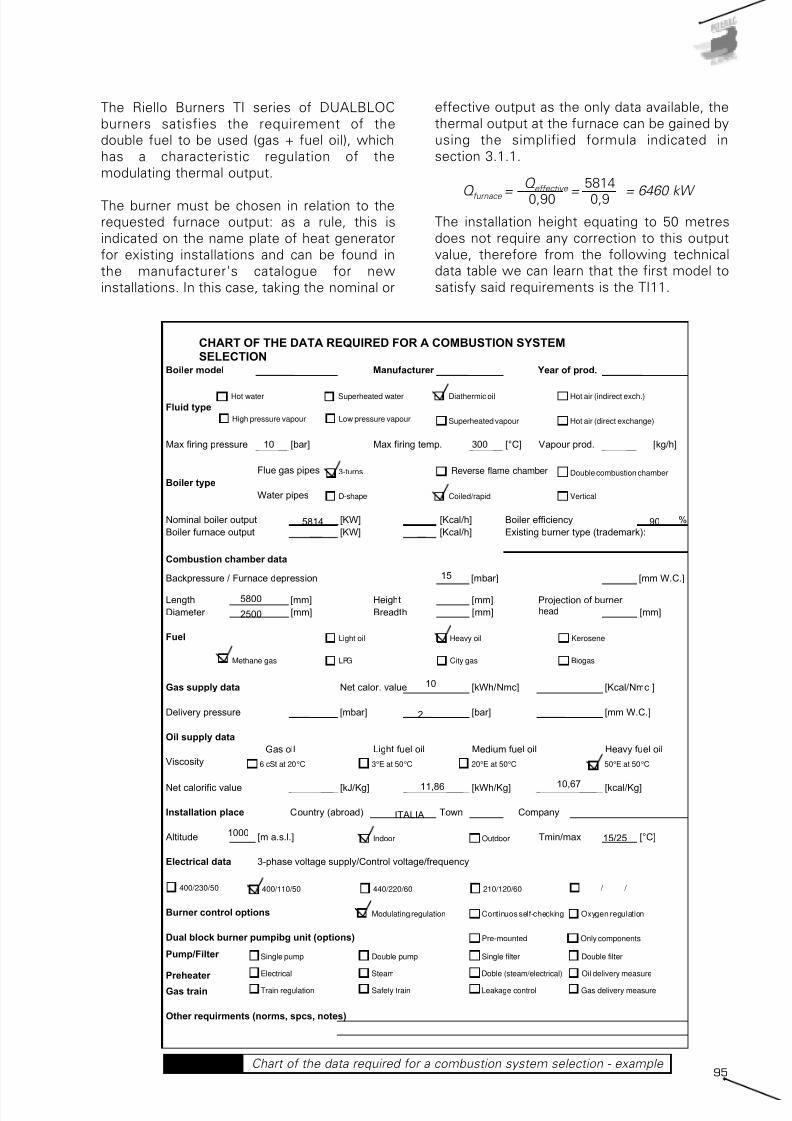
7/25/2019 Riello Burner Handbook
http://slidepdf.com/reader/full/riello-burner-handbook 94/169
95
The Riello Burners TI series of DUALBLOC
burners satisfies the requirement of the
double fuel to be used (gas + fuel oil), which
has a characteristic regulation of the
modulating thermal output.
The burner must be chosen in relation to the
requested furnace output: as a rule, this is
indicated on the name plate of heat generator
for existing installations and can be found in
the manufacturer's catalogue for new
installations. In this case, taking the nominal or
effective output as the only data available, the
thermal output at the furnace can be gained by
using the simplified formula indicated in
section 3.1.1.
The installation height equating to 50 metres
does not require any correction to this output
value, therefore from the following technical
data table we can learn that the first model to
satisfy said requirements is the TI11.
Q furnace = = = 6460 kW
Q effective
0,90
5814
0,9
CHART OF THE DATA REQUIRED FOR A COMBUSTION SYSTEMSELECTION
Boiler model Manufacturer Year of prod.
Fluid type
Max firing pressure [bar] Max firing temp. [°C] Vapour prod. [kg/h]
Flue gas pipes
Boiler type
Water pipes
Nominal boiler output [KW] [Kcal/h] Boiler efficiency %
Boiler furnace output [KW] [Kcal/h] Existing burner type (trademark):
Combustion chamber data
Backpressure / Furnace depression [mbar] [mm W.C.]
Length [mm] Height [mm] Projection of burner headDiameter [mm] Breadth [mm] bruciatore [mm]
Fuel
Gas supply data Net calor. value [kWh/Nmc] [Kcal/Nmc ]
Delivery pressure [mbar] [bar] [mm W.C.]
Oil supply data
Gas oil Light fuel oil Medium fuel oil Heavy fuel oil
Viscosity
Net calorific value [kJ/Kg] [kWh/Kg] [kcal/Kg]
Installation place Country (abroad) Town Company
Altitude [m a.s.l.] Tmin/max [°C]
Electrical data 3-phase voltage supply/Control voltage/frequency
Burner control options
Dual block burner pumpibg unit (options)
Pump/Filter
Preheater
Gas train
Other requirments (norms, spcs, notes)
Diathermic oilHot water Superheated water
Superheated vapourHigh pressure vapour
Hot air (indirect exch.)
3-turns Flame inversion
Low pressure vapour
Light oil Heavy oil
LPGMethane gas Biogas
Indoor Outdoor
400/230/50 400/110/50 210/120/60440/220/60 / /
Continuos self-checking Oxygen regulation
Pre-mounted
Single pump
Double combustion chamber
Coiled/rapid
Kerosene
City gas
6 cSt at 20°C 20°E at 50°C3°E at 50°C 50°E at 50°C
Double pump Single filter Double filter
Electrical Steam Doble (steam/electrical)
Train regulation Safety train Leakage control Gas delivery measure
D-shape
Oil delivery measure
Modulating regulation
Only components
Hot air (direct exchange)
Vertical
10 300
5814
15
5800
2500
90
10
2
11,86 10,67
ITALIA
100015/25
Chart of the data required for a combustion system selection - example Table 28
Reverse flame chamber
head

7/25/2019 Riello Burner Handbook
http://slidepdf.com/reader/full/riello-burner-handbook 95/169
96
F u e l / A i r D a t a
E l e c t r i c a l D a t a
E m i s s i o n s
A p p r o v a l
Intermittent (at least one stop every 24 h) - Continuos (at least one stop every 72 h)
TI 10
1 : 6
1 : 5
1 : 4
1 : 3
870/3000÷5200
748/2580÷4472
1040/3000÷5200
894/2580÷4472
1300/3000÷5200
1118/2580÷4472
1700/3000÷5200
1462/2580÷4472
111/253÷438
152/268÷464
87/300÷520
101/349÷605
40/116÷202
Servo-
motor
natural gas
LPG
light oil
heavy oil
s
kW
Mcal/h
kW
Mcal/h
kW
Mcal/h
kW
Mcal/h
°C min./max.
kWh/kg
Kcal/kg
mm2/s (cSt)
Kg/h
°C
kWh/kg
Kcal/kg
mm2/s (cSt)
Kg/h
°C
bar
kWh/Nmc
kg/Nmc
Nmc/h
kWh/Nmc
kg/Nmc
Nmc/h
kWh/Nmc
kg/Nmc
Nmc/h
type
°C max.
Ph/Hz/V
type
VA
A
IP
V1 - V2
I1 - I2
dBA
W
mg/kWh
N° Bach.
mg/kWh
mg/kWh
N° Bach.
mg/kWh
mg/kWh
mg/kWh
modulating
SQM10
42
-15/60
11,8
10200
4 ÷ 6
50
11,1÷11,3
9545÷9720
500
140
25÷28
10
0,71
8,6
0,78
25,8
2,02
Centrifugal with reverse curve blades
150
1/50-60/230 - (1/50-60/110 on request)
LFL 1.333 - LFL 1.335 (Intermittent working) - LGK 16 (Continuos working)
630
2,7 - 5,7
54
230 V - 1x8 KV
1,4A - 30 mA
--
--
< 110
< 1
< 250
Depending on the fuel amount
Depending on the fuel amount
Depending on the fuel amount
< 100
< 170
89/336 - 73/23 - 98/37 - 90/396 CEE
EN 267 - EN 676
--
TI 12
1 : 6
1 : 5
1 : 4
1 : 3
1450/6000÷8700
1247/5160÷7482
1740/6000÷5700
1496/5160÷7482
2170/6000÷8700
1866/5160÷7482
2900/6000÷8700
2494/5160÷7482
183/506÷734
259/536÷777
145/600÷870
169/698÷1012
67/233÷337
natural gas
LPG
light oil
heavy oil
TI 14
1 : 5
1 : 4
1 : 3,5
1 : 3
2400/8500÷12000
2064/7310÷10320
3000/8500÷12000
2580/7310÷10320
3400/8500÷12000
2924/7310÷10320
4000/8500÷12000
3440/7310÷10320
287/717÷1012
357/759÷1071
240/850÷1200
279/988÷1395
116/329÷465
TI 11
1 : 6
1 : 5
1 : 4
1 : 3
1160/4200÷7000
998/3612÷6020
1400/4200÷7000
1204/3612÷6020
1750/4200÷7000
1505/3612÷6020
2330/4200÷7000
2004/3612÷6020
148/354÷590
208/375÷625
116/420÷700
135/488÷814
54/163÷271
TI 13
1 : 6
1 : 5
1 : 4
1 : 3
1830/7800÷11000
1574/6708÷9460
2200/7800÷11000
1892/6708÷9460
2750/7800÷11000
2365/6708÷9460
3660/7800÷11000
3148/6708÷9460
232/658÷927
326/696÷982
183/780÷1100
213/907÷1279
85/302÷426
Heat
Output
Light
oil
Heavy
oil
G20
G25
LPG
Light
oil
Heavy
oil
G20
Model
Setting type
Modulation ratio at
max output
type
run time
Working temperature
net calorific value
viscosity at 20°C
Output
max temperature
net calorific value
viscosity at 20°C
Output
max temperature
Atomised pressure
net calorific value
Density
Output
net calorific value
Density
Output
net calorific value
Density
Output
Fan
Air temperature
Electrical supply
Control box
Auxiliary electrical power
Total current
Protection level
Ignition
transformer
Operation
Sound pressure
Sound output
CO emission
Grade of smoke indicator
NOx emission
CO emission
Grade of smoke indicator
NOx emission
CO emission
NOx emission
Reference directive
Reference norms
Certifications
Reference conditions:
Temperature: 20°C - Pressure: 1013.5 mbar - Altitude: 100 meters a.s.l. - Noise measured at a distance of 1 meter.
Chart of the data required for a combustion system selection - example Table 29
After this preliminary choice, a check must be
made on the firing range.
The firing range for separately powered
burners is represented by a histogram that
identifies the minimum and maximum outputs
that can be developed by the burner.
The TI firing ranges are shown below both for
methane gas and fuel oil (naphtha) feeding.
These diagrams illustrate the firing ranges
relating to the two usual temperature values.
50°C in the case of combustion supporter airnot reheated and 150 °C for processes where
the combustion supporter air is pre-heated.
Looking at the diagrams with furnace output
equal to 6,460 kW, it is evident how the TI11
model, which develops a thermal output of 7
MW with combustion supporter air at 50 °C is
not applicable with pre-heated air at a
temperature of 150 °C. The choice therefore
falls on the TI12 model.
3.3.2 Selection of the fan
The information required to choose the fanincludes air delivery and the head required to
guarantee that the combustion supporter air
participates correctly in the combustion
process.

7/25/2019 Riello Burner Handbook
http://slidepdf.com/reader/full/riello-burner-handbook 96/169
97
Calculating the combustion supporter air
delivery
The combustion supporter air delivery is
proportionate to the delivery of burnt fuel,
therefore
The fan must therefore satisfy the additional
air delivery from among those requested by
the various fuels, in this case it is therefore
Gair = 7848 mc/h.
Since the installation is at a height of 1,000
metres above sea level and at a temperature
of 40 °C, to guarantee an equal number of
moles of oxygen, this delivery must be
corrected using the F factor obtaining:
If the manufacturer provides the characteristic
data and curves of the fans already corrected
to the intake temperature, the correction must
be realised solely in function of the height
obtaining:
G air = = = 8739 kW corrected (H,T) 7848
0,898
G air
F
G air = = = 9331 kW corretta (H,T) 7848
0,841
G air
F
G air = x gtheoretical air x eG 20= x
x 9,56 x 1,20 = 7410 mc/h
Q foc
PCIG 20
G 20 G 20 6460 10,0
G air = x g theoretical air x e fuel oil
=
x 10,37 x 1,25 = 7848 mc/h
fuel oil fuel oil Q foc
PCIfuel oil
6460 10,67
Calculating the fan head
The fan head is the sum of the head at
combustion head exit and the induced
pressure drops in the air pipelines and from
the combustion head.
Called Hfan, the effective head of the fan, the
following conditions must be checked:
Hfan ≥ H1 + H2 + H3 + H4
where,
H1 = back pressure in the combustion
chamber;
H2 = pressure drop in the combustion head;
H3 = pressure drop in the air pipelines;
H4 = pressure drop in the heat exchangers;
The pressure drops must all refer to the
effective air temperature and heights.
Combustion chamber
The backpressure in the combustion chamber
is project-related data and is equal to H1 =
1,500 Pa.
Combustion head
The pressure drop in the combustion head is
taken from the diagrams supplied by the
burner manufacturer.
For burners with a movable head, we must
consider the characteristic curve obtained in
the laboratory for the same layout of the head
set for actual functioning .
In this case, the drop in the burner head is
therefore equal to H2 = 27 mbar = 2,700 Pa.
This value refers to a test temperature equal to
Test conditions conforming EN 267; EN 676:
Temperature: 20°C - Pressure: 1013.5 mbar - Altitude: 100 m.s.l.
1000 2000 3000 4000 5000 6000 7000 8000 9000 10000 11000 1000 2000 3000 4000 5000 6000 7000 8000 9000 10000 110000
0
kW0 2000 4000 6000 8000 10000 12000
0
0
kW0 2000 4000 6000 8000 10000 12000
Useful working field for choosing the burner Modulation range
GAS OIL
A i r t e m p e r a t u r e ° C
A i r t e m p e r a t u r e ° C
Mcal/h
TI 14
TI 13
TI 12
TI 11
TI 10
50°C
150°C
50°C
150°C
50°C
150°C
50°C
150°C
50°C
150°C
Mcal/h
TI 14
TI 13
TI 12
TI 11
TI 10
50°C
150°C
50°C
150°C
50°C
150°C
50°C
150°C
50°C
150°C
Firing ranges for Riello TI Series of burner combustion heads Diagram 92

7/25/2019 Riello Burner Handbook
http://slidepdf.com/reader/full/riello-burner-handbook 97/169
98
20°C, therefore the value obtained will becorrected with the following Kc (4) factor
relating to a temperature of 150 °C, taken from
the law of perfect gases (see section 2.5).
The correct pressure drop will therefore be
equal to
H2 = 27 x 1.44 = 38,8 mbar = 3898 Pa
The air which arrives at the head is taken in at
a height greater than the standard laboratory
test height; for this reason, the pressure dropmust be further corrected by dividing H2 by
the F factor relating to a height of 1,000
metres above sea level.
The effective pressure drop of the head will
therefore be equal to
H2 = 38.98 x 1,114 = 43.43 mbar = 4343 Pa
The distribution ducts
The calculations of the dimensions of the air
delivery duct section must satisfy various
requirements:
• limit the head requested at the fan;
• limit the internal air speed;
• respect the available dimensions.
In this case, since there are no dimension
limits, a maximum speed of 20 m/s is fixed
and at the end of the calculation we will check
that the loss induced by the duct does not
exceed the value of 500 Pa. From the
following diagram, for a speed of 20 m/s and a
delivery of 2,586 l/s (9,331 mc/h) the diameter
of the section of the ducts is equal to 450 mm.
Again on the diagram, we can read the related
distributed pressure drop equating to e = 9
Pa/m.
The duct also presents two gentle 90° curves,
which have a non-dimensional loss factor
equal to ξ = 1, thus we can calculate the
related pressure drops with the known formula
with a hypothetical duct length of 20 m, the H3pressure drop is therefore
H3=
ε
. L + 2 .
∆pw = 9 . 20 + 2 . 220 =620 Pa.
The air in the ducts or pipelines is however
taken in under temperature and height
conditions that are different from standard
ones; this leads to a variation in air density and
therefore a variation in the pressure drops. The
value of H3 obtained as above must therefore
be corrected by using the Kc = 1,19 factor
relating to the intake conditions (5) of the fan
(40 °C, 1,000 metres above sea level).
∆p w = = 1 . 1,1 . 202 / 2 = 220 Pa.ξ .ρv2
2
m b a r
10
40
20
30
50
kW
0
Mcal/h
∆P
P e r d i t a
d i c a r i c o
60
9000 1100050003000 70001000 13000 15000
2800800 68004800 8800 10800 12800
T I 1 4
T I 1 0
T I 1 1 T I
1 2
T I 1 3
Combustion head pressure drops
for TI series - air side Diagram 93
m 0 20 30 40 50 60 70 80 90 100 120 140 150
0 0,920 0,987 1,021 1,055 1,088 1,122 1,156 1,189 1,223 1,257 1,324 1,391 1,425100 0,932 1,000 1,034 1,068 1,102 1,136 1,171 1,205 1,239 1,273 1,341 1,409 1,443
500 0,976 1,047 1,083 1,119 1,154 1,190 1,226 1,261 1,297 1,333 1,404 1,476 1,511
750 1,006 1,079 1,116 1,153 1,190 1,227 1,263 1,300 1,337 1,374 1,448 1,521 1,5581000 1,038 1,114 1,152 1,190 1,228 1,266 1,304 1,342 1,379 1,417 1,493 1,569 1,607
1250 1,067 1,145 1,184 1,223 1,262 1,301 1,340 1,379 1,418 1,457 1,535 1,613 1,6531500 1,101 1,182 1,222 1,263 1,303 1,343 1,384 1,424 1,464 1,505 1,585 1,666 1,706
1750 1,136 1,220 1,261 1,303 1,344 1,386 1,428 1,469 1,511 1,552 1,636 1,719 1,760
2000 1,174 1,259 1,302 1,345 1,388 1,431 1,474 1,517 1,560 1,603 1,689 1,775 1,8182250 1,206 1,294 1,339 1,383 1,427 1,471 1,515 1,559 1,604 1,648 1,736 1,824 1,869
2500 1,251 1,342 1,388 1,434 1,480 1,525 1,571 1,617 1,663 1,709 1,800 1,892 1,9382750 1,284 1,378 1,425 1,472 1,519 1,566 1,613 1,660 1,707 1,755 1,849 1,943 1,990
3000 1,321 1,417 1,466 1,514 1,562 1,611 1,659 1,708 1,756 1,804 1,901 1,998 2,046
s. l. m. 0d. m. a.d. n. m. a.
s. l.
c
ARIA / LUFT / AIR / AIR °C
Kc - correction factor of discharge head and delivery in relation to temperature and altitude Table 30
Kc
(4) The Kc correction factor is the inverse of the F correction factor.
(5) The increase transformation of the temperature which takes place in the exchanger is isochor (volume=constant) therefore the density
remains constant and the specific pressure drops do not change.
P r e s s u r e d r o p

7/25/2019 Riello Burner Handbook
http://slidepdf.com/reader/full/riello-burner-handbook 98/169
99
H3 = Kc. H3 = 1,19 . 620 = 737.8 Pa
The heat exchanger
The heat exchanger should be chosen in
relation to the air, the nominal flue gas delivery
and the related increase in temperature of the
combustion supporter air.
Two effects cause the pressure variation in the
heat exchanger:
• the isochor transformation (at constant
volume), where the flue gases release heatinto the air;
• the mechanical resistor of the tube nest.
Heat exchanger manufacturers supply the
characteristic curve for each heat exchanger
taken from given input and output height and
temperature conditions.
This value must be corrected as a result of the
different input/output temperatures and the
various installation heights.
The exchanger introduced into this system has
a pressure drop, corresponding to the delivery
of 9331 mc/h and a temperature increase of
110 °C (from 40°C to 150 °C), equal to
H4 = 500 Pa
The exchanger is however installed at 1,000
metres above sea level, therefore this drop
must be corrected by using the parameter Kc,
thereby obtaining
H4 = 500 · 1.114 = 557 Pa
The effective fan head
The effective head that the fan must provide is
therefore equal to
Hfan = H1 + H2 + H3 + H4 = 1.000 + 4.343 +
620 + 300 = 6,320 Pa = 63,20 mbar
From the tables provided by the manufacturer,
similar to those below, we can choose the
model of fan.
In this case, the manufacturer provides the
characteristic running values with air at 40 °C,
therefore entering the table relating to
effective heads of around 600 mm (6000 Pa)
with a value of the corrected air delivery
Gcorrected(H) of 8739 mc/h, we can obtain
the fan model: GBJI06360, for which we must
also indicate the orientation of the pressure
Pressure drops in circular pipelines Diagram 94
3000 4000 5000 6000 7000 8000 9000 10000 11000 12000 13000 14000 15000 16000 17000 18000 19000 20000
Fan model
GBJH05630 600 550 500 450 400 300
GBJI06310 650 625 600 550 525 500GBJH06320 710 700 675 650 600 550
GBJH06380 760 710 680 640
GBJI06340 700 675 650 630GBJI06320 650 600 575 535 490 450 390 330
GBJI06360 740 700 660 625 590 550 500 450 400
GBJH07120 840 810 790 750 700 650 600
GBJI07100 830 875 850 825 800 770 740GBJH07170 940 910 880 850 800 750 700 625 560 490 410
GBJI07080 810 780 755 725 695 650 610 585 530 490 425 390 330
GBJI07120 895 875 850 820 790 750 720 690 640 585 545 495 440GBJI0800A 1025 1005 990 875 845 910 885 855 815 790 750
Delivery (m 3 /h)
Static air pressure (mmH 2 O)
Fans selection table Table 31
Pressure drop (mm H2O) for 1 m length
A
i r d e l i v e r y ( m 3 / h )
A i r d e l i v e r y ( m 3 / h )

7/25/2019 Riello Burner Handbook
http://slidepdf.com/reader/full/riello-burner-handbook 99/169
100
ALTITUDE (m a.s.l.)
Temperature (°C) 4000 3000 2000 0-1000
0 1,98 1,2 1,3 1,3
10 1 1,1 1,2 1,3
20 0,9 1 1,1 1,2
30 0,8 0,9 1 1,1
40 0,7 0,8 0,9 1
50 0,6 0,7 0,8 0,9
60 0,5 0,6 0,7 0,8
Nominal output declassing factor inrelation to temperature and altitude Table 32
inlet in relation to the intake inlet.
The effective firing point of the fan must be
verified on the real characteristic curve.
As we can see from the diagram, the firing
point falls halfway through the characteristic
curve of the fan, which is thus verified.
A further check can be carried out, when
working at high altitudes, by declassing the
motor, which gives a reduction in nominaloutput as the temperature and altitude
increase. From graphs and tables similar to the
following, supplied by the electric motor or fan
manufacturers, the reduction factor is obtained
for the motor nominal output; this must always
be greater than the power absorbed by the fan
at the effective working output. It is important
to remember that the absorbed power by the
fan is reduced by the F correction factor
previously used for elevated altitudes and
temperatures.
3.3.3 Selection of the gas train
Generally, the gas train comprises two groups
of components:
• The safety and regulating valves;
• The pressure reduction unit.
The safety unit is chosen in relation to the
combustion head pressure drops on the gasside; for the Riello Burner the characteristic
curves from the gas side of the TI burner
series for G20 natural gas are shown below.
For a furnace output of 6,410 kW, the sum of
the drops of the gas butterfly valve and the
head is equal to 24+6=30 mbar (3,000 Pa).
Using the diagram 97, we can choose the size
of the safety value unit (6) DMV100/1, which
has pressure drops equal to approximately 30
mbar (3,000 Pa).
The sum of the pressure drops in the head and
the valve unit is therefore:
Hgas = (Hhead + Hbutterfly) + Hvalve = 30+30 =
= 60 mbar
The feed pressure of the gas is equal to 2 bar,
therefore a reducer unit is necessary to
guarantee an outgoing pressure equal to 60
mbar and a gas delivery equal to
Ggas = Qfoc / PCIgas = 6,410 / 10 = 641 Nm3 / h
Static air pressure GBJ series
250
350
450
550
650
750
850
950
1050
1000 3000 5000 7000 9000 11000 13000 15000 17000 19000
mc/h
m m w . c . GBJ H06320
GBJ H05630 11kW
GBJ I06340 18,5 kW
GBJ H07120 30kW
GBJ H07170 37kW
GBJ I06310 15kW
GBJ I06320 18,5kW
GBJ I06360 22kW
GBJ I07080 37 kW
GBJ I07100 37kW
GBJ I07120 45kW
GBJ I0800A 55kWGBJ H06380 22kW
Performence graphs of GBJ fan series Diagram 95
(6) The safety and regulating value unit comprises: a double automatic shut off valve and a low point pressure switch.

7/25/2019 Riello Burner Handbook
http://slidepdf.com/reader/full/riello-burner-handbook 100/169
101
P r e s s u r e
d r o p
Butterfly valve losses
Combustion head losses
G25
0
20
10
8
6
4
2
12
14
16
18
m b a r
10
40
20
30
50
kW
2800800 68004800
9000 11000
0
5000 3000 7000
8800 10800
1000
Mcal/h
G20∆P
P r e s s u r e
d r o p
60
70
12800
13000
T I 1 4
T I 1 0
T I 1 1
T I 1 2
T I 1 3
∆P
m b a r
DN 100
DN 80
TI 10
TI 11
TI 12
TI 13
T I 1 4
2800800 68004800 8800 10800 Mcal/h 12800
kW 9000 11000 5000 3000 1000 13000
G25
0
20
40
50
30
10
60
70
80
90
2
8
4
6
10
0
12
14
16G20
Reference conditions:Temperature: 15°CPressure: 1013.5 mbar
Reference conditions:Temperature: 15°CPressure: 1013.5 mbar
Combustion head and butterfly valve pressure drops for TI series - gas side Diagram 96
Pressure drops in DMV safety valves Diagram 97

7/25/2019 Riello Burner Handbook
http://slidepdf.com/reader/full/riello-burner-handbook 101/169
102
From the table of pressure reducers for high
pressure Riello Burners (>500 mbar - max 4
bar) we can choose the reducer unit (7) HPRT750 with the BP type spring, which guarantees
outgoing pressure regulation ranging from 60
to 110 mbar.
3.3.4 Selection of the thrust unitfor liquid fuel and the nozzles
In separate feed burners, the pre-heating and
liquid fuel thrust components are separate
from the burner body mounted on the heatgenerator.
To complete the burner, a suitable thrust unit
must therefore be chosen, both with regards
type and nominal running characteristics.
First, the functioning philosophy must be
determined, which in this case we can
presume is the type with a single pumping unit
with electrical pre-heating.
We must then take the pressure values of thecombustion head fuel oil Phead and fuel oil
delivery mpumping.
The first can be gained from the technical data
table for the TI12 burner
Phead = 25 ÷ 28 bar.
The delivery of the pumping unit must be
approximately double the nominal delivery
required for combustion:
taking the fuel oil density as d =0.97 kg/l we
obtain:
mpumping / δ = 1210.8 / 0.97 = 1248.2 l/h
mpumping = 2 . mburner = =
2 . = 1210,8 kg / h
Q foc
PCIfuel oil
646010,67
3/400/503/440/60
Version Heating type PH/V/HZ Port sizeDelivery
[l/h]@15 bar
Delivery[l/h] @30
bar
Motor power[KW] - 50 Hz
Maxoutputkg/h
Heatingpower KW
250 EP3/400/503/440/60
1/2" 580 540 1,1 265 14
320 EP3/400/503/440/60
3/4" 950 700 1,5 350 20
400 EP3/400/503/440/60
3/4" 1400 1200 2,2 540 28
500 EP3/400/503/440/60
3/4" 1400 1200 2,2 590 40
650 EP3/400/503/440/60
3/4" 1900 1700 3 775 40
800 EP3/400/503/440/60
3/4" 1900 1700 3 835 42
1000 EP3/400/503/440/60
1" 2700 2200 5,5 1085 60
1500 EP3/400/503/440/60
1" 5400 3600 7,5 1550 80SN 4EP20
SN 3EP14
SN 3EP20
SN 2EP20
SN 2EP20
SN 1EP20
SN 2EP14
Model type Electrical heaters
Heavy oil electrical heating/pumping unit skid - single pumping unit
SN 1EP14
Pumping unit skids selection table Table 34
DN in Reg Valve DN out
MaxPress.[bar]
InletPress.[bar]
Maxdelivery
G 20
[Nmc/h]
Maxdelivery
LPG
[Nmc/h]1"1/2 D 50 1"1/2 4 1,5 70 45
1"1/2 D 100 2" 4 1,5 140 90
2" D 160/32 65 4 1,5 225 144
65 D 250/40 65 4 1,5 422 270
80 D 250/50 80 4 1,5 765 490
100 N 50 100 4 1,5 1150 736
100 N 65 100 4 1,5 1350 864
125 N80 125 4 1,5 2360 1510
1500 150220
HPRT 750 100200
HPRT 2000 150220
HPRT 1000 155230
HPRT
HPRT 250 65120
HPRT 500 100200
HPRT 80 2760
HPRT 160 2760
Model type Version
High pressure regulating train ( Pi > 500 mbar - max 4 bar )
Outlet pressure
High pressure regulating/reducing units selection table Table 33
(7) The reduction unit comprises: a manual shut off valve, a filter, a pressure regulator with safety valve, an anti-vibration joint and twopressure probes.

7/25/2019 Riello Burner Handbook
http://slidepdf.com/reader/full/riello-burner-handbook 102/169
103
Modeltype
NoteSpryangle
Maxcapacity
[kg/h]
Part.n°
B5-45-AA TI 10 - TI 11 - TI12 - TI 13 45 250 3009802
B5-45-AA TI 10 - TI 11 - TI12 - TI 13 45 275 3009803
B5-45-AA TI 10 - TI 11 - TI12 - TI 13 45 300 3009804
B5-45-AA TI 10 - TI 11 - TI12 - TI 13 45 325 3009805
B5-45-AA TI 10 - TI 11 - TI12 - TI 13 45 350 3009806
B5-45-AA TI 10 - TI 11 - TI12 - TI 13 45 375 3009807
B5-45-AA TI 10 - TI 11 - TI12 - TI 13 45 400 3009808
B5-45-AA TI 10 - TI 11 - TI12 - TI 13 45 425 3009809
B5-45-AA TI 10 - TI 11 - TI12 - TI 13 45 450 3009810
B5-45-AA TI 10 - TI 11 - TI12 - TI 13 45 475 3009811
B5-45-AA TI 11 - TI 12 - TI 13 45 500 3009812
B5-45-AA TI 11 - TI 12 - TI 13 45 525 3009813
B5-45-AA TI 11 - TI 12 - TI 13 45 550 3009814
B5-45-AA TI 11 - TI 12 - TI 13 45 575 3009815
B5-45-AA TI 11 - TI 12 - TI 13 45 600 3009816
B5-45-AA TI 11 - TI 12 - TI 13 45 650 3009817
B5-45-AA TI 12 - TI 13 45 700 3009818
B5-45-AA TI 12 - TI 13 45 750 3009819
B5-45-AA TI 12 - TI 13 45 800 3009820
B5-45-AA TI 13 45 850 3009821
B5-45-AA TI 13 45 900 3009822
B5-45-AA TI 13 45 950 3009823
Spill back nozzles for mechanical atomizing
2-Stages - Progressive modulating
Modulating nozzle delivery
100
200
300
400
500
600
700
800
900
1000
1100
1200
0 5 10 15 20 25 30
Return pressure (atm)
D e l i v e r y ( k g / h )
Ppump=30atm
Ppump=25atm
Ppump=20atm
Pumping unit skids selection table Table 35
Nozzles delivery for modulating burners Diagram 98

7/25/2019 Riello Burner Handbook
http://slidepdf.com/reader/full/riello-burner-handbook 103/169
104
Looking at the fuel oil delivery column at a
pressure of 30 bar, from the table for choosing
the electrical pre-heating and thrust units with
single pumping unit in Riello Burners, we can
obtain the thrust unit model, which is the
SN500
Selection the nozzles
The nozzles must be chosen in relation to the
type of fuel atomisation, the thermal load
regulation type and the combustion chamber
dimensions. In this case, atomisation is
mechanical, load regulation is modulating and
the combustion chamber has a standard
length/diameter ratio.
Looking at the maximum delivery column of the
mechanical atomisation nozzles with a spray
angle of 45° , we can choose the nozzle which
has a nominal fuel delivery slightly greater than
the theoretical one requested by the burner.
The correct nozzle is therefore the B3-45-AA
650 kg/h code No. 3009817.
Verification of the correct load modulating ratio
requested of 1:5 must be made on the diagram
provided by the nozzle manufacturer, in
relation to the maximum and minimum fuel
pressure in the return circuit. In this case, we
have 650/130=5 mad therefore the requested
modulating ratio is possible.
mburner = = = 605,4 kg / hQ foc
PCIfuel oil
646010,67
3.3.5 Selection of thecomponents in the liquid fuelfeed circuit
The liquid fuel feed circuit taken into
consideration is the following:
The circuit shown in the diagram is the most
appropriate when using heavy oil with a
viscosity between 7°E and 65 °E measured at
50°C.
This feed system comprises two ring circuits
plus a transfer circuit; the principal one for
circulating the heavy oil from the service tank,
the secondary one for circulating the oil from
the primary circuit to the burner and the
transfer one for transferring fuel oil from the
storage tank to the service tank. All the circuitsare controlled by their own pump, those for
the primary circuit and transfer circuit should
be chosen by the design engineer, while those
for the secondary circuit are provided as
standard fittings with the burner.
As far as the primary ring and transfer ring are
concerned, the viscosity pumping limit is
usually around 70°E at 50°C. Therefore, for
these circuits a temperature of 50-60°C can
be considered as more than sufficient to avoid
blocking the pipelines.
The heavy oil must therefore be taken to acertain temperature for it to be adequately
atomised and subsequently burnt in the
combustion chamber. To obtain an adequate
Layout of a heavy oil feeding circuit Diagram 99
BR Dualbloc burnerB Gas separator bottleF Oil filter 300 microns degreeMM Oil delivery gaugeP(MP) Pumping group – transfer ringP1(MP) Pumping group – burner circuit with filter
and pressure regulatorP2(MP) Pumping group - main circuit with filterPS Electrical oi l preheaterRS1 Pump heater resistanceRS2 Oil tank heater resistanceSB Main oil tankSB2 Service oil tankT ThermometerTE Temperature switch regulation
TF Flexible oil lineTF1 Flexible oil line pressure 25-30barTP Temperature probeTM Max oi l pressure switchVC Vent valveVG Supply air fanVR1 Oil pressure regulator valve of
the oil burner ringVR2 Oil pressure regulator valve of the
oil main ringVS Preheater safety valveVG7 Safety valve
VG Double valvesHeavy oil pipe with electricalpreheater cable
modulating burner

7/25/2019 Riello Burner Handbook
http://slidepdf.com/reader/full/riello-burner-handbook 104/169
105
atomisation of the fluid oil, the range of
viscosity goes from 2°E to 5°E at 50°C. To
obtain this viscosity value, the heaviest fuel
oils must be pre-heated up to 130°C.
Naphtha burners in the Riello Burners range
are equipped with electrical modulating pre-
heaters regulated by a series of regulating and
safety thermostats capable of reaching the
temperatures required for atomising the fuel.
Furthermore, for the heaviest fuel oil special
kits for heavy oil must be used, comprising a
series of electrical elements for the secondary
feed circuit pump.
For dimensioning the circuit equipment, the
following initial data is take for reference
purposes:
Effective length of intake pipelines Leff
= 15 m;
Equivalent length of intake pipelines
Lequiv=10 m;
Effective length of delivery pipeline Leff= 30 m;
Equivalent length of delivery pipeline
Lequiv=20 m;
pump tank height difference ∆hgeom = 1 m;
project-related temperature t = 60°C;
volume mass of heavy fuel oil at the reference
temperature (15°C) = 990 kg/m3;
viscosity γ at 50°C = 50°E (approx.. 400·10-6
m2 /s);
viscosityγ
at 60°C = 40°E (approx. 200·10-6
m2 /s);
fuel oil thrust unit delivery 1,200 kg/h = 20.7
l/min.
3.3.5.1 Transfer pump between the
storage tank and the service tank
The transfer circuit pumping plant must
comprise a couple of pumps equipped with
their own filters and with the possibility of
switchover in by-pass.
Both the pumps, suitable for heavy fuel oil
(with gears), must be chosen with a delivery
equal to 1.2-1.5 times the maximum peak
consumption of the system, in this case:
mpump1 = (1,2 → 1,5) . mpumping = (1,2 → 1,5) .
1200 = 2400 kg / h
These pumps must be equipped with a self-
cleaning blade filter (comb-type) with mesh
dimension ranging between 400 and 600 mm
and pre-heated to 50-60°C.
It is well to the remember that to avoid
problems on the intake pipelines, the pumping
plant should be positioned as near as possible
to the storage tank.
3.3.5.2 Service tank
The service tank, which also acts as an outgas
device, is a hydraulic disconnection element
between the transfer stretch and that of the
main ring. This tank must have the following
characteristics:
• fuel oil entry from the base;
• double pre-heater, one fluid heater (water
or vapour) to be positioned immediately above
the arrival point of the heavy fuel oil and an
electrical pre-heater above the fluid pre-heater
with integration and emergency functions;
• drawing of the heavy fuel oil above the two
pre-heaters;
• tank capacity equal to at least 2-3 times the
sum of the maximum hourly drawing
capacities of the burners;
In this case, the tank has a capacity equal to:
V = (2 → 3 ) .mpumping = (2 → 3) . 20,74 l /min
. 60 min = 2488 → 3733 l
This volume should be taken as effective,
entirely occupied by the heavy fuel oil; a quota
must be calculated equal to 10% of additional
volume for the gases and vapours emitted by
the oil.
In addition, the service tank must be equipped
with the following devices:
• end plate outlet for water and sediment;
• level control with minimum and maximum
alarm equipped with self-checking systems;
• atmosphere breather pipe;
• "over full" device with return line to storage
tank;
3.3.5.3 Pump in the main ring
The pumping plant in the main ring must
comprise a couple of pumps with their own
filters and the possibility of switchover in by-
pass.
Both the pumps in the main ring should be
chosen on the basis of the fluid delivery and
viscosity at the temperature of the circulation
fluid. The pumps in the main rings must be
dimensioned for a minimum delivery equal to

7/25/2019 Riello Burner Handbook
http://slidepdf.com/reader/full/riello-burner-handbook 105/169
106
at least 3-5 times the sum of the maximum
drawing capacities of the burners.
mpump = (3 → 5 ) .mpumping = (3 → 5) . 1200 =
3600 → 3733 kg / h
These pumps must be equipped with a self-
cleaning blade filter (comb-type) with mesh
dimension ranging between 200 and 300 mm
and pre-heated to 50-60°C, the pumping plant
should be positioned as near as possible to the
storage tank.
We can presume using a pump with the
following characteristics:
Q = 4,000 kg/h (1,11 kg/s);
H = 30 m approx.
and a self-cleaning filter with meshes of 250
mm which, for delivery of approximately 4,000
kg/h introduces a pressure drop of 3,000 Pa.
The ring circuit must be equipped with a
pressure-regulating valve, with a regulating
interval ranging between 1 and 4 bar and with
a nominal delivery greater than that of the
circuit corresponding to a pump delivery.
3.3.5.4 Dimensioning the main ring
pipelines
The pipelines must be made from black steel
tubes without welding joints. The pipelines
must be marked using an electrical heating
wire with an output between 20 and 40 W/m
or using heating fluid. For easier installation
and maintenance operations, the pipeline can
be marked with a copper tube (diameter 12x1-
20x1) within which the heating wire can run.
The pipelines must be insulated in closed-cell
foam.
The diameter of the circuit pipeline must be
dimensioned on the basis of the following
considerations:
minimum speed in the intake pipelines
(upstream from the pumps): 0.15 m/s;
maximum speed in the delivery pipelines
(downstream from the pumps): 0.6 m/s;
The heavy fuel oil volume mass at a
temperature of 60°C is equal to:
The intake pipeline must be dimensioned so
ρ = =
= 963 [kg/m3]
ρ15
1 + β . (t - 15) 9901 + 0,00063 . (60 - 15)
that the pressure drop in that stretch does not
exceed the following value:
∆P prog = ∆P amn - ∆hasp - ∆P acc [Pa ]
where:
∆P amn = absolute pressure allowed at intake(NPSH) indicated by the pump manufacturer;
otherwise, this pressure must not be less than
50,660 Pa (0.5 ata);
∆hasp = intake height;
∆P acc = head loss due to the presence of
accessories (filters, etc…)
The intake height is equal to:
∆hasp = ∆hgeom.ρ .9,81 [Pa ]
where:∆hgeom= difference in height between the fuel
test point in the tank and the centre of the
feed pump [m];
ρ = volume mass of the heavy fuel oil [kg/m3];
The value is positive if the tank is lower than
the burner, and negative if the tank is higher.
In this case, we have the following values:
∆hasp = ∆hgeom.ρ .9,81 = 1 . 963 . 9,81 =
9.447 [Pa ]
therefore, the maximum pressure dropallowed along the pipeline will be equal to:
∆P prog = ∆P amn - ∆hasp - ∆P acc = 50.660 -
9.447 - 3.000 = 38.213 [Pa ]
The minimum internal diameter of the pipeline
is obtained using the following formula:
If we presume using an iron DN100 (4”)
pipeline with an internal diameter of 101.6 m,
the transfer speed is equal to:
which is greater than the minimum allowed
safety value of 0.15 m/s.If the transfer speed is lower than the limit
value of 0.15 m/s, we should proceed as
follows:
V =Q
A= = = 0,356 m/s
π . d2
4
Q
0,00087
0,278963
d = =42 . γ . LTOT .m
∆P prog √4
42 . 200 . 10-6 . 25 .1,11
39.713√4
= 0,276 m

7/25/2019 Riello Burner Handbook
http://slidepdf.com/reader/full/riello-burner-handbook 106/169
107
choose the pipeline diameter that guarantees
the minimum speed using the formula:
the total maximum length (effective +
equivalent) of the connection pipeline between
the tanks and the pump is determined, so as
not to exceed the project-related pressure
drops using the following formula:
In the pressurised stretches, i.e. the pipeline
downstream from the pump, the fluid speed
can reach 0.6 m/s, which in our case gives a
pipeline with the following diameter:
therefore, we will choose a DN25 (1”) iron
pipeline that has an internal diameter equal to
0.0278 metres.
The pressure drops distributed along the
pipeline will be equal to:
This value added to the concentrated pressure
drops introduced by the special components
(filters, valves, etc.) not calculated in the
equivalent lengths, must be less than the head
supplied by the pumping system.
3.3.6 Selection of the electricalcontrol panel
The types of electrical power supply and
control signals for a DUALBLOC burner
depend on the size of the components that
make up the combustion system and the type
of regulation of the thermal load.
The manufacturers have tables for choosing
the electrical power supply and control panels
in relation to the type of burner, its maximum
developed output and the type of regulation.
In this case, the electrical panel will be chosen
from the table relating to TI dual-fuel (heavy oil
∆P prog = = =
= 195.486 Pa (≅20 m approximately)
42 . 200 . 10-6 . 50 . 0,278
0,02784
42 . γ . LTOT . m
d4
√ √ π . 0,6
4 . Q
π . 0,15d = = = 0,0248 m
0,2789634 .
LTOT =d4 . ∆Pprog
42 . γ . m
A = π . = d⇒Q
V
d2
4 ⇒Q
V=√ 4 . Q
π . 0,15
and natural gas) burners looking at the
developed output column, in correspondence
with the maximum value of 7,800 kW for a
TI12 burner, we can read the initials of the
electrical panel required QA12 NM and the
related absorbed electrical output,
corresponding to an electrical power supplywith three-phase current.
This latter information must be provided by the
design engineer of the heating plant electrical
systems where the heavy oil generator in
question will be installed.
Model typeBurner output
[kW]
FanAbsorbed
Power [KW]
HeatingAbsorbed
power [KW]
Pump Absorbedpower [KW]
Heatingtype
QA 10 PNM - 1A TI 10 max 3900 11 20 1,5 EP
QA 10 PNM - 1BTI 10 max 3900
11 15 1,5 EVQA 10 PNM - 2A TI 10 max 4600 11 28 2,2 EP
QA 10 PNM - 2B TI 10 max 5000 11 15 2,2 EV
QA 11 PNM - 1A TI 11 max 5400 15 28 2,2 EP
QA 11 PNM - 1B TI 11 max 5400 15 15 2,2 EV
QA 11 PNM - 2A TI 11 max 6200 15 40 2,2 EP
QA 11 PNM - 2B TI 11 max 6200 15 20 2,2 EV
QA 11 PNM - 3A TI 11 max 7000 22 40 3 EP
QA 11 PNM - 3B TI 11 max 7000 22 25 3 EV
QA 12 PNM - 1A TI 12 max 7700 22 40 3 EP
QA 12 PNM - 1B TI 12 max 7700 22 25 3 EV
QA 12 PNM - 2A TI 12 max 8500 30 42 3 EP
QA 12 PNM -2B TI 12 max 8500 30 30 3 EV
QA 13 PNM - 1A TI 13 max 9300 30 42 3 EP
QA 13 PNM - 1B TI 13 max 9300 30 30 3 EV
QA 13 PNM - 2A TI 13 max 10800 37 60 5,5 EP
QA 13 PNM - 2B TI 13 max 10800 37 40 5,5 EVQA 14 PNM - 1A TI 14 max 11600 55 60 5,5 EP
QA 14 PNM - 1B TI 14 max 11600 55 40 5,5 EV
QA 14 PNM - 2A TI 14 max 12400 55 80 7,5 EP
QA 14 PNM - 2B TI 14 max 12400 55 50 7,5 EV
Heavy oil/Natural gas dualbloc burners control panel
Nozzles selection table Table 36

7/25/2019 Riello Burner Handbook
http://slidepdf.com/reader/full/riello-burner-handbook 107/169
109
4.1 INSTRUMENTS
The following instruments are required to
correctly measure combustion efficiency:
1. Carbon dioxide CO2 analyser / or Oxygen
O2 analyser;
2. Carbon monoxide CO analyser (gas only);
3. Measuring instruments for the
“Bacharach” smoke grade index (liquid fuels
only);
4. Thermometer for measuring combustion
supporter air temperature;
5. Thermometer for measuring the
temperature of combustion products;
6. Thermometer for measuring the
temperature of the boiler fluid;
7. Chronometer.
The instruments listed in points 1, 2, 3, 4 and
5 can be replaced by a single multi-function
device similar to that illustrated in diagram 87;
4.2 PRELIMINARY OPERATIONS
Before proceeding with calculating
combustion efficiency, the effective capacity
at the furnace where the measurement will be
taken must be gauged; this can be determined
by measuring the fuel delivery and multiplying
it by the related inferior calorific value.
Since it is not possible to determine the fuel
delivery effectively burnt using the following
methods; we will take the value declared by
the manufacturer as the reference thermal
output.
The reference capacity at the furnace must be
equal to or lower than the maximum output at
the furnace.
The measurement methods for both liquid and
gaseous fuels, of the delivery of fuel burnt are
illustrated as follows.
4.2.1 Systems fired by liquid fuel
We proceed with the weighing method, with a
tank filled with a known volume of fuel which
is sucked in by the burner for a determinate
period. The volume of fuel consumed divided
by the test time provides the fuel delivery
value.
A simplified method, with an error margin up
to 10%, involves verifying the size of the
nozzle(s), and taking the atomisation pressure
of the nozzle; referring to the tables of the
nozzles mounted on the burner we can obtain
the fuel delivery value (usually expressed in
kg/h). This data should be multiplied by the
corresponding inferior calorific value, thus
obtaining the capacity effectively burnt.
Ready-to-use tables exist, which in relation to
the nozzle delivery and the pump pressure
provide the delivery of the liquid fuel.
4.2.2 Systems fired by gaseousfuel
In systems powered by mains gas, fuel
delivery is taken by reading the meter; to
calculate the output effectively burnt, the
above methods are valid.
We recommend paying great attention when
reading the meter in that, if it is placed on a
high pressure gas feed line, account must be
taken of the gas compressibility; in fact by
MEASURING COMBUSTION EFFICIENCY
4
Example of analyzer for measuring
combustion efficiency
Diagram 100

7/25/2019 Riello Burner Handbook
http://slidepdf.com/reader/full/riello-burner-handbook 108/169
110
compressing a gas, its is reduced volume but
the number of molecules remains constant,i.e. density increases following the
subsequent law. In this case, the reading,
which is volumetric, will be lower than the
effective mass-related delivery,
Where:
P1= gas pressure at a density of δ1;
P2= gas pressure at a density of δ2;
A simplified formula (valid only for meter
pressure greater than 40 mbar) for correcting
the delivery values read in relation to the
pressure, is illustrated as follows:
Where
Vvc = correct delivery of gas [Nm
3
/h]Vvi= measured delivery in terms of volume
[Nm3 /h]
P = gas pressure at the meter [mbar]
Another simple method for calculating the
effective gas delivery is represented by using
the correction factors in the table, in relation to
the pressure and the temperature read off the
meter. Several of these tables are illustrated in
section 5 of this manual.
In systems without meters, a calibrateddiaphragm must be fitted to the feed pipeline,
or alternatively, the combustion head pressure
can be used as an indication.
V vc =1013 + P
1013V vi
P 1 = P 2. δ1
δ2
Gas flow characteristics measuring points Diagram 101
4.3 MEASUREMENT CONDITIONS
AND OPERATING METHODS
The measurements must be carried out when
the heat generator is in a steady running state
(for example: at around 70 ° C for hot water
generators) and at the maximum output at the
furnace for such measurements.
To correctly take these measurements, the
following must be performed:
1. Make a hole with a sufficient diameter for
inserting the probes used for the
measurements (approximately 10 mm.), in theflue gas connector, boiler/flue, two diameters
in distance from the generator outlet, if
available, use the specific hole provided by the
heat generator manufacturer;
2. Ensure that there is no seepage of air prior
to the hole for drawing off the combustion
products (seal any holes, slits, etc…), because
secondary air would alter the measured
values, thereby discrediting the test;
3. Bring the heat generator to steady running
state (for example: around 70° C for hot water
heat generators);4. For each single parameter take at least
three measurements, at equal intervals during
the test period deemed necessary by the
operator, and each time at least 120 seconds
after beginning the sample;
5. Seal the hole made for the measurements;
6. Transcribe the measured data, where the
value measured of each individual parameter is
obtained from the arithmetic mean of the first
three significant measurements (any
anomalous measurements must not be taken
into account).

7/25/2019 Riello Burner Handbook
http://slidepdf.com/reader/full/riello-burner-handbook 109/169
111
4.4 CALCULATING THE
COMBUSTION EFFICIENCY
The fuel efficiency _ of a generator can be
calculated by using the following formula, with
the drop at the generator shell considered asnil.
η = 100 - P s ± 2%
Where:
η heat generator efficiency;
Ps is the thermal output lost via the flue;
and ±2% is the tolerance linked to
uncertainties relating to the measuring
instruments and the reading of the parameters
measured.
As has already been seen in paragraph 1.5.1,
the conventional formulas used fordetermining losses via the flue are:
if the concentration of oxygen free in the
combustion flue gases is known, or:
if the concentration of carbon dioxide in the
combustion flue gases is known.
where:
Ps = thermal output lost via the flue [%];
Tf = temperature of the flue gases (°C);
Ta = temperature of the combustion supporter
air (°C);
O2 = concentration of oxygen in the dry flue
gases [%];
CO2 = concentration of carbon dioxide in the
dry flue gases [%];
A1, A2 and B are some empirical factors
whose values are shown in the table below.
P s = . (Tf - Ta )( )A2
CO2+ B
P s = . (Tf - Ta )( )A1
21 - O2+ B
Leaving aside the measured value of fuel
efficiency, to consider combustion satisfactory
the concentration of CO must be checked
referred to the condition of dry combustion
products and without air at lower than 0.1%
(1000 ppm).
The concentration of CO dry flue gases
without air is provided by the equation:
where:
COm is the amount of carbon monoxide
measured
CO2theoretical is the theoretical CO2CO2measured is the measured CO2The values of CO2 theoretical are illustrated in
Table 5 of section 1 - Maximum and
recommended CO2 levels for various fuels.
The same can be said, for heat generators
powered by liquid fuel, if the smoke grade
index referred to the Bacharach (8) scale, is
greater than 2 for diesel oil and greater than 6
for fuel oil.
4.1.1 Example for calculatingcombustion efficiency
Let us examine the following measured
values:
Fuel: natural gas
Measurement of CO2: 9.6%
Temperature of flue gases Tf: 170 ° C
Temperature of combustion supporter air Ta: 30°C
Measurement of CO: 80 ppm
Theoretical CO2: 11,7%
Since we know the value of CO2 present in
the flue gases, we can obtain the following
thermal output value lost at the flue:
The fuel efficiency of the generator referred to
the thermal output of the furnace for which the
measurement was carried out, is given by:
η = 100 - 6,94 = 993,06 ±2%
To conclude, the concentration of CO must be
checked referred to the condition of dry
combustion products without air:
equal to 0.0107 % < 0.1 %
CO dry flue gases without air = 88 x = 107,25 ppm11,79,6
P s = + 0,010 . (170 - 30) = 6,94( )0,389,6
CO dry flue gases without air= CO m xCO 2 theoretical
CO 2 measured
Fuel
METHANE
L.P.G.
LIGHT OIL
HEAVY OIL
A1
0,66
0,63
0,68
0,68
A2
0,38
0,42
0,50
0,52
B
0,010
0,008
0,007
0,007
Coefficients for calculation of
combustion efficiency
Table 37
(8) The Bacharach measurement method has already been described in section 1.

7/25/2019 Riello Burner Handbook
http://slidepdf.com/reader/full/riello-burner-handbook 110/169
112
5.1 MEASURING UNITS AND CONVERSION FACTORS 115
1.1 Units of International system SI and main conversion factors 115
1.2 Units used for heat transfer calculations 116
1.3 Conversion factors among the units of measurment 117
1.3.1 Lenght 117
1.3.2 Area 117
1.3.3 Volume 118
1.3.4 Mass 119
1.3.5 Pressure 119
1.3.6 Work, energy, heat, enthalpy 120
1.3.7 Power (mechanical, electric and thermal) 1201.3.8 Velocity 121
1.3.9 Flow rate in volume 121
1.3.10 Other conversion factors for non SI units 122
1.4 Conversion of inches and fractions of inch in millimetres 123
1.5 Temperature conversion tables 124
1.6 Standard voltages and frequencies in different countries 126
1.7 Personal units of measurment and conversion factors 128
5.2 TABLES AND DIAGRAMS ABOUT FUEL VISCOSITY 129
1.8 Approximated equivalence table between viscosity measurements
at the same temperature 129
1.9 Nomograph for viscosity units conversions 130
1.10 Viscosity variations in relation to temperature for different fuels 131
1.11 Gas dynamic viscosity 132
5.3 TABLES AND DIAGRAMS FOR CIRCUITS DIMENSIONING 134
1.12 Distributed pressure drops in air circular ducts 134
1.13 Equivalence between circular and rectangulare sections of air ducts 135
1.14 Air ducts dimensioning: loss coefficients for special pieces in circular
and rectangular pieces 136
1.15 Distributed pressure drops in air pipelines for liquid and gaseous fuels 138
1.16 Liquid fuel feeding circuit dimensioning: equivalent lenght of
main concentrated resistances 140

7/25/2019 Riello Burner Handbook
http://slidepdf.com/reader/full/riello-burner-handbook 111/169
113
1.17 Dispersion of heavy oil tanks 141
1.18 Compensation of thermal dispersions in steady condition 142
1.19 Calculation of total needed output 143
1.20 Diagram for passing from energy to output 144
1.21 Diagram for pipelines tracing with heating bands 145
1.22 Nozzle delivery with liquid fuels 146
1.23 Commercial features of steel and copper pipelines 150
1.24 Correction factors for lecture of gas delivery from gas meters 152
1.25 Graphical method for determining energy saving by use of inverter 155
5.4 TABLES AND DIAGRAMS ABOUT COMBUSTION 156
1.26 Combustion triangle for natural gas and light/heavy oil 156
1.27 Combustion air and gas burnt quantities in relation to air excess
for different fuels: G20, LPG, light oil and heavy oil 157
1.28 Increase of temperature in exhausted gas in relation to soot thickness 161
1.29 Lenght and diameter of the flame in relation to burner output 162
1.30 SO2 emissions (mg/m3 e mg/kWh) in oil combustion in relation
of S content (%) in the fuel at 3% of O2 163
1.31 NOx emissions in relation to the different parameters of influence 164
1.32 Efficiency loss in exhausted gasses in relation to O2 content for different fuels 166
1.33 Efficiency loss in exhausted gasses in relation to CO2 content for different fuels 168
1.34 Conversion factors for pollutant emissions 170

7/25/2019 Riello Burner Handbook
http://slidepdf.com/reader/full/riello-burner-handbook 112/169

7/25/2019 Riello Burner Handbook
http://slidepdf.com/reader/full/riello-burner-handbook 113/169
115
READY-TO-USE TABLES AND DIAGRAMS
5
5.1 MEASURING UNITS AND CONVERSION FACTORS
1.1 Units of International system SI and main conversion factors

7/25/2019 Riello Burner Handbook
http://slidepdf.com/reader/full/riello-burner-handbook 114/169
116
1.2 Units used for heat transfer calculations

7/25/2019 Riello Burner Handbook
http://slidepdf.com/reader/full/riello-burner-handbook 115/169
117
1.3 Conversion factors among the units of measurment
1.3.1 Lenght
1.3.2 Area

7/25/2019 Riello Burner Handbook
http://slidepdf.com/reader/full/riello-burner-handbook 116/169
118
1.3.3 Volume

7/25/2019 Riello Burner Handbook
http://slidepdf.com/reader/full/riello-burner-handbook 117/169
119
1.3.4 Mass
1.3.5 Pressure

7/25/2019 Riello Burner Handbook
http://slidepdf.com/reader/full/riello-burner-handbook 118/169
120
1.3.6 Work, energy, heat, enthalpy
1.3.7 Power (mechanical, electric and thermal)

7/25/2019 Riello Burner Handbook
http://slidepdf.com/reader/full/riello-burner-handbook 119/169
121
1.3.8 Velocity
1.3.9 Flow rate in volume

7/25/2019 Riello Burner Handbook
http://slidepdf.com/reader/full/riello-burner-handbook 120/169
122
1.3.10 Other conversion factors for non SI units

7/25/2019 Riello Burner Handbook
http://slidepdf.com/reader/full/riello-burner-handbook 121/169
123
1.4 Conversion of inches and fractions of inch in millimetres

7/25/2019 Riello Burner Handbook
http://slidepdf.com/reader/full/riello-burner-handbook 122/169
124
1.5 Temperature conversion tables

7/25/2019 Riello Burner Handbook
http://slidepdf.com/reader/full/riello-burner-handbook 123/169
125

7/25/2019 Riello Burner Handbook
http://slidepdf.com/reader/full/riello-burner-handbook 124/169
126
1.6 Standard voltages and frequencies in different countries
Country Frequency (Hz) Voltage/s (V) Country Frequency (Hz) Voltage/s (V) Afghanistan 50 220/380 Dominican republic 60 110/220
Algeria 50 127/220 Ecuador 60 120/208
50 220/380 60 127/220
American samoa 60 240/480 60 120/240
Angola 50 220/380 Egypt 50 220/380
Antigua 60 230/400 El salvador 60 115/230
Argentina 50 220/380 England (and Wales) 50 240/480
Australia (East zone) 50 240/415 50 240/415
(West zone) 50 254/440 Equatorial guyana 50 220
Austria 50 220/380 Ethiopia 50 220/380
Azorse 50 220/380 ex - U.S.S.R. 50 220/380
Bahamas 60 120/208 ex-Yugoslavia 50 220/380
60 115/200 Far Oer 50 220/380
60 120/240 Fiji 50 240/415
Bahrain 50 230/400 Finland 50 220/38060 230/400 France 50 220/380
Bangladesh 50 220/380 50 110/220
50 230/400 50 115/230
Barbados 50 110/190 50 127/220
50 120/208 50 500
50 115/200 French guyana 50 220/380
50 115/230 Gabon 50 220/380
Belgium 50 127/220 Gambia 50 220/380
50 220/380 Germany 50 220/380
50 220 Ghana 50 220/380
Belize 60 110/220 Gibraltar 50 240/415
60 220/440 Greece 50 220/380
Benin 50 220/380 Grenada 50 2307400
Bermuda 60 120/240 Guadeloupe 50 220/380
60 120/208 Guam 60 120/208
Bolivia 50 110/220 60 110/220
50 220/380 Guatemala 60 120/240
50 115/230 60 120/20860 220/380 Guinea 50 220/380
Botswana 50 220/380 Guinea bissau 50 220/380
Brazil 60 110/220 Guyana 50 110/220
60 220/440 60 110/220
60 127/220 Haiti 50 220/380
60 220/380 60 110/220
60 115/220 Honduras 60 110/220
60 125/216 Honk kong 50 200/346
60 230/400 Iceland 50 220/380
50 220/440 India 50 220/380
Bulgaria 50 220/380 50 230/400
Burundi 50 220/380 Indonesia 50 220/380
Cambodia 50 220/380 50 127/220
50 120/208 Iran 50 220/380
Camerun 50 127/220 Iraq 50 220/380
50 220/360 Ireland 50 220/380
50 230/400 Isle of Man 50 240/415
Canada 60 120/240 Israel 50 230/400
60 575 Italy 50 220/380
Canarie 50 127/220 50 127/220
50 220/380 Ivory coast 50 220/380
Cape Verde 50 220/380 Jamaica 50 110/220
Cayman Islands 50 220/380 Japan 50 100/200
Central african republic 50 220/380 60 100/200
Chile 50 220/380 Jerusalem 50 220/380
China 50 220/380 Jordan 50 220/380
Ciad 50 220/380 Kenya 50 240/415
Colombia 60 110/220 Korea 60 100/200
60 150/260 0 220/380
60 440 Kuwait 50 240/415
Congo 50 220/380 Laos 50 220/380
Costarica 60 120/240 Lebanon 50 110/190
Cuba 60 120/240 50 220/380
Cyprus 50 240/415 Lesotho 50 220/380
Czech republic 50 220/380Denmark 50 220/380

7/25/2019 Riello Burner Handbook
http://slidepdf.com/reader/full/riello-burner-handbook 125/169
127
Country Frequency (Hz) Voltage/s (V) Country Frequency (Hz) Voltage/s (V)Liberia 60 120/208 Sri Lanka 50 230/400
60 120/240 St. Kitts & Nevis 60 230/400
Libya 50 127/220 St. Lucia 50 240/416
50 220/380 St. Vincent 50 230/400
Luxembourg 50 220/380 Sudan 50 240/415
50 120/208 Suriname 60 115/230
Macao 50 220/380 50 127/220
Madagascar 50 220/380 Swatziland 50 230/400
50 127/220 Sweden 50 220/380
Majorca 50 220/380 Switzerland 50 220/380
50 127/220 Syria 50 220/380
Malawi 50 220/380 Tahiland 50 220/380
Malaysia 50 240/415 Tahiti 60 127/220
Maldives 50 230/400 Taiwan 60 110/220
Mali 50 220/380 Tanzania 50 230/400Malta 50 220/380 Togo 50 127/220
Martinique 50 220/380 50 220/380
Mauritius 50 240/415 Tonga 50 240/415
Mexico 60 127/220 Trinidad & Tobago 60 115/230
Monaco 50 220/380 60 230/400
50 127/220 Tunisia 50 127/220
Monzambique 50 220/380 50 220/380
Morocco 50 127/220 Turkey 50 220/380
60 220/380 Uganda 50 240/415
Nepal 50 220/440 United Arab Emirates 50 220/380
Netherland antilles 60 220/380 Uruguay 50 220
60 115/230 USA 60 600
50 120/208 60 120/240
50 127/220 60 460
Netherlands 60 220/380 60 575
New Zeland 50 230/400 Venezuela 60 120/208
Niacaragua 60 120/240 Vietnam 50 120/208
Niger 50 220/380 50 127/220Nigeria 50 240/415 50 220/380
Northern Ireland 50 230/400 Virgin islands 60 120/240
50 230 Yemen 50 220/380
Norway 60 220/380 50 230/400
Oman 50 220/380 Zaire 50 220/380
Pakistan 50 220/380 Zambia 50 220/380
50 230/400 Zimbawe 50 220/380
Panama 60 110/220
60 115/230
60 120/208
Papua Nuova Guinea 50 240/415
Paraguay 50 220/380
Perù 60 110/220
50 220
Philippines 60 110/220
Poland 50 220/380
Portorico 60 120/208
Portugal 50 220/380Qatar 50 240/415
Romania 50 220/380
Ruanda 50 220/380
Saudi Arabia 60 127/220
50 220/380
Scotland 50 240/415
Senegal 50 127/220
Seychelles 50 240
Sierra Leone 50 220/380
Singapore 50 230/400
Slovakia 50 220/380
Somalia 50 110/220
50 220/440
50 220/380
South Africa 50 220/380
Spain 50 220/380
50 127/220
In case the higher value is double than lower, there is a single phasesystem with three conductors with two main conductors and anintermediate conductor.
In case the higher value is 1,73 times more then lower, there is a threephase system with 4 conductors with 3 main conductors and a conductorconnected to the star-centre.220/380V voltage are being replaced from230/400V.
In case of a single value, there is a three phase system with three mainconductors.

7/25/2019 Riello Burner Handbook
http://slidepdf.com/reader/full/riello-burner-handbook 126/169
128
1.7 Personal units of measurment and conversion factors

7/25/2019 Riello Burner Handbook
http://slidepdf.com/reader/full/riello-burner-handbook 127/169
129
5.2 TABLES AND DIAGRAMS ABOUT FUEL VISCOSITY
1.8 Approximated equivalence table between viscosity measurements atthe same temperature

7/25/2019 Riello Burner Handbook
http://slidepdf.com/reader/full/riello-burner-handbook 128/169
130
1.9 Nomograph for viscosity units conversions
Cinematic viscosity, Centistokes
Cinematic viscosity, Centistokes
Saybolt universla seconds
Redwood I seconds
Engler degrees
Saybolt furol seconds
Redwood II seconds

7/25/2019 Riello Burner Handbook
http://slidepdf.com/reader/full/riello-burner-handbook 129/169
131
1.10 Viscosity variations in relation to temperature for different fuels
V i s c o s i t y ( m m 2 / s )
Temperature (°C)
V i s c o s i t y ( ° E )
A – MAX and MIN limits of Gas oil (D) range
B – light fuel oil (E) range
D – medium fuel oil (F) range
E – adviced limits of nozzle viscosity
F – economical limit value for pumpability of fuel oil

7/25/2019 Riello Burner Handbook
http://slidepdf.com/reader/full/riello-burner-handbook 130/169
132
1.11 Gas dynamic viscosity

7/25/2019 Riello Burner Handbook
http://slidepdf.com/reader/full/riello-burner-handbook 131/169
133

7/25/2019 Riello Burner Handbook
http://slidepdf.com/reader/full/riello-burner-handbook 132/169
134
5.3 TABLES AND DIAGRAMS FOR CIRCUITS DIMENSIONING
1.12 Distributed pressure drops in air circular ducts
A i r d e l i v e r y ( m 3 / h )
A i r d e l i v e r y ( m 3 / h )
Pressure drop (mmH2O) for 1 m lenght

7/25/2019 Riello Burner Handbook
http://slidepdf.com/reader/full/riello-burner-handbook 133/169
135
1.13 Equivalence between circular and rectangulare sections of air ducts
SMALLER SIDE
D U C T
D I A M E T E R
d .
B I G G E R
S I D E

7/25/2019 Riello Burner Handbook
http://slidepdf.com/reader/full/riello-burner-handbook 134/169
136
1.14 Air ducts dimensioning: loss coefficients for special pieces incircular and rectangular pieces
Plane curve
Plenum
Obstruction Obstruction Obstruction

7/25/2019 Riello Burner Handbook
http://slidepdf.com/reader/full/riello-burner-handbook 135/169
137
CuveGuidingfin
without fins
diafphragm
withfins
Bifurcation
Jumber tube
Free intake
Divergence
Narrowing
Drilled metal sheets
free section in %
w is referredto the total
section
for net grilles ζvalues areabout a half
ζ for w = 0,5 m/s

7/25/2019 Riello Burner Handbook
http://slidepdf.com/reader/full/riello-burner-handbook 136/169
138
1.15 Distributed pressure drops in air pipelines for liquid and gaseousfuels
PROCEDURE
1) Individuate on the horizontal axis at the top of square “1” fuel oil delivery required
2) Go down vertically until intersecating in square “2” the oblique line corresponding to oil viscosity
at ref. temperature: two scales, in cSt and °E, are reported.
3) From intersection point proceed horizontally in the left direction until intersecating in square “3”
the oblique line corresponding to pipeline lenght
4) From intersection point proceed upwards until intersecating in square “4” the oblique lines
corresponding to different pressure drops in m c. H2O
5) At this point it is possible to procced in two ways: or it is prefixed max. pressure drop; then from
intersection point with oblique line proceed horizontally in the right direction and on vertical axisof square “1” read pipeline diameter (mm and inches are reported). Otherwise from pipeline
diameter, pressure drops are obtained with opposite procedure.
Speed (m/s)

7/25/2019 Riello Burner Handbook
http://slidepdf.com/reader/full/riello-burner-handbook 137/169
139
0 , 1
0 , 2
0 , 3
0 , 4
0 , 5
0 , 6
0 , 7
0 , 8
1
2
3
4
5
1 0
6
2 0
5 0
6 0
1 0 0
8 0
2 0 0
4 0 0
8 0 0
1 0 0 0
6 0 0
3 6 9 1 2
1 5
2 2
3 0
4 5
6 1
7 6
9 5
1 2 2
1 5 2
V
P E R D I T E D I C A R I C O : m b a r
1
2
3
4
5
6
7
8
1 0
2 0
3 0
4 0
D I A
M E T R O T U B O : R p
1 , 4
L U N G
H E Z Z
A T U
B O : m
e t r i
1 / 2
3 / 4
1 "
1 " 1 / 2
6 "
1 " 1 /
4
4 "
3 "
2 " 1 /
2
2 "
1 5 , 3
4
= Portata gas Nm3/h
f1 - G20
= 0,62 - G25
1,18 - G31
f V Gas delivery
P I P E
L I N E L E N
G T H
( m )
P R E S S U R E D R O P : m b a r
P I P E L I N E D I A M E T E R : R p

7/25/2019 Riello Burner Handbook
http://slidepdf.com/reader/full/riello-burner-handbook 138/169
140
1.16 Liquid fuel feeding circuit dimensioning: equivalent lenght of mainconcentrated resistances

7/25/2019 Riello Burner Handbook
http://slidepdf.com/reader/full/riello-burner-handbook 139/169
141
1.17 Dispersion of heavy oil tanks
PROCEDURE
1) Individuated on the left horizontal axis project ∆T (difference between heavy oil temperature and
min. external), trace a vertical line until intersecating line relative to the specific tank. Zone 1
correspond to non isolated vertical tanks, line 2 is relative to horizontal grounded tanks and line
3 to vertical isolated tanks,
2) From intersection point proceed horizontally in the right direction and individuate on vertical axis
the dispersion for m2 of tank external surface;
3) Evaluated external surface of tank, individuate the value on right horizontal axis; if this value is
missing, make use of bottom axis where volume of vertical and horizontal tanks is reported
(typical commercial values);
4) Trace vertical until intersecating previous horizontal line relative to dispersion for m2 of tank;
5) The line correspondant to intersection point represents dispersions of tank when it is completely
full of preheated heavy oil.
External vertical tank non
isolated
Grounded tank
External vertical tank
isolated

7/25/2019 Riello Burner Handbook
http://slidepdf.com/reader/full/riello-burner-handbook 140/169
142
PROCEDURE
1) Individuate on the left horizontal axis pipeline diameter,
2) Trace vertical until intersecating oblique line correspondant to project ∆T between heavy oil and
external temperature;
3) Trace from intersection point an horizontal line in the right direction and evaluate on vertical axisdispersion for 1 m of pipeline;
4) Extend horizontal line until intersecating oblique line relative to pipeline lenght;
5) Trace vertical and read on the right horizontal axis the total output required.
1.18 Compensation of thermal dispersions in steady condition
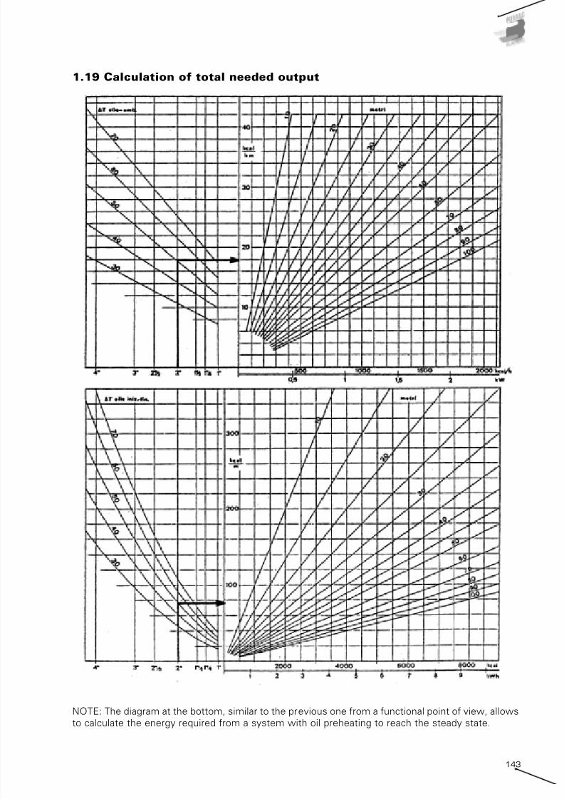
7/25/2019 Riello Burner Handbook
http://slidepdf.com/reader/full/riello-burner-handbook 141/169
143
1.19 Calculation of total needed output
NOTE: The diagram at the bottom, similar to the previous one from a functional point of view, allows
to calculate the energy required from a system with oil preheating to reach the steady state.

7/25/2019 Riello Burner Handbook
http://slidepdf.com/reader/full/riello-burner-handbook 142/169
144
1.20 Diagram for passing from energy to output
NOTE: The diagram allows, once knew energy to reach steady state, to calculate output, which
depends from warm-up time (represented in hours from oblique lines).
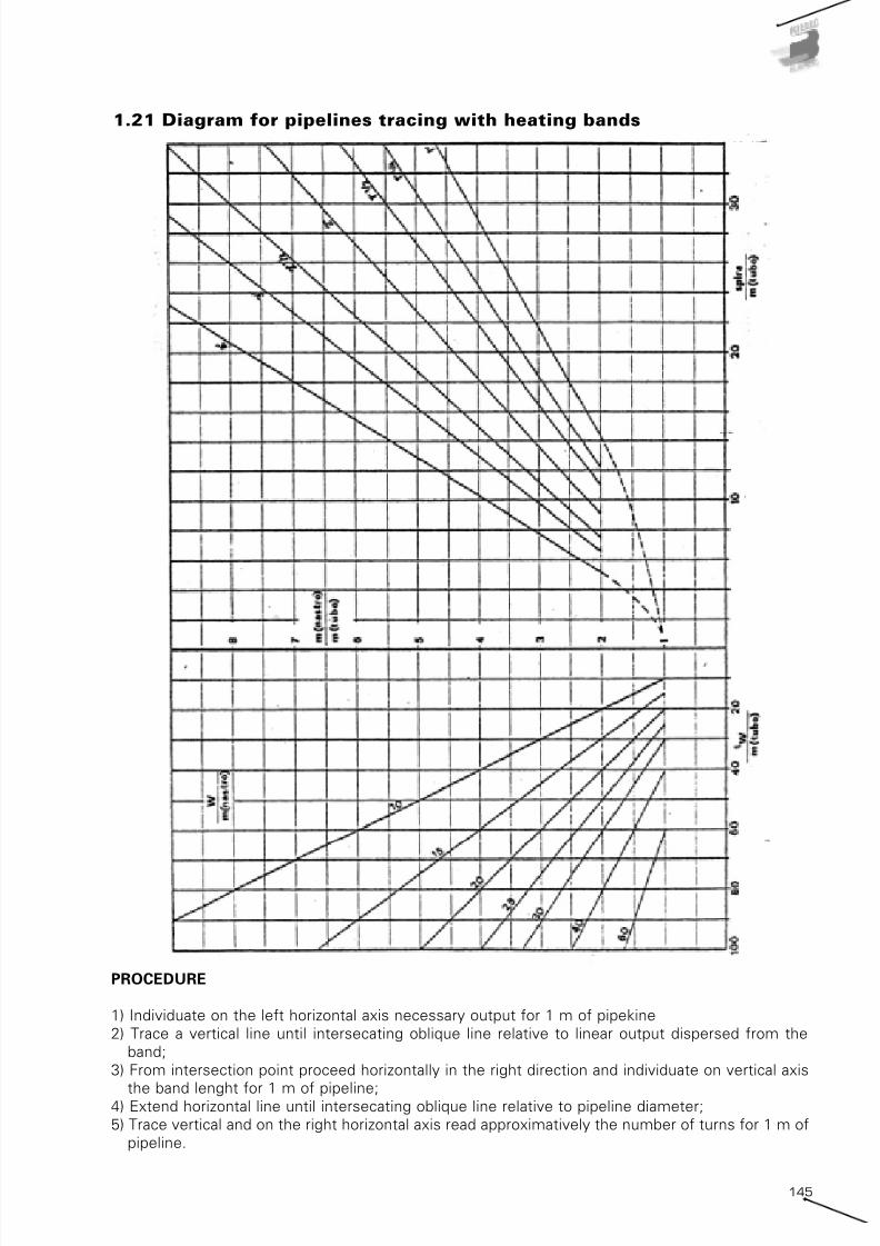
7/25/2019 Riello Burner Handbook
http://slidepdf.com/reader/full/riello-burner-handbook 143/169
145
1.21 Diagram for pipelines tracing with heating bands
PROCEDURE
1) Individuate on the left horizontal axis necessary output for 1 m of pipekine
2) Trace a vertical line until intersecating oblique line relative to linear output dispersed from the
band;
3) From intersection point proceed horizontally in the right direction and individuate on vertical axis
the band lenght for 1 m of pipeline;4) Extend horizontal line until intersecating oblique line relative to pipeline diameter;
5) Trace vertical and on the right horizontal axis read approximatively the number of turns for 1 m of
pipeline.

7/25/2019 Riello Burner Handbook
http://slidepdf.com/reader/full/riello-burner-handbook 144/169
146
1.22 Nozzle delivery with liquid fuels
Nozzle nominal delivery (GPH) 10 11 12 13 14 150,4 1,41 1,48 1,55 1,62 1,69 1,75
0,5 1,76 1,85 1,94 2,02 2,11 2,19
0,55 1,93 2,03 2,13 2,23 2,32 2,41
0,6 2,11 2,22 2,33 2,43 2,53 2,62
0,65 2,28 2,40 2,52 2,63 2,74 2,84
0,75 2,64 2,77 2,91 3,04 3,16 3,28
0,85 2,99 3,14 3,30 3,44 3,58 3,72
1 3,51 3,70 3,88 4,05 4,21 4,37
1,1 3,87 4,07 4,27 4,45 4,64 4,81
1,25 4,39 4,62 4,85 5,06 5,27 5,47
1,35 4,74 4,99 5,24 5,47 5,69 5,91
1,5 5,27 5,55 5,82 6,07 6,32 6,56
1,65 5,80 6,10 6,40 6,68 6,95 7,22
1,75 6,15 6,47 6,79 7,09 7,38 7,66
2 7,03 7,40 7,76 8,10 8,43 8,752,25 7,91 8,32 8,73 9,11 9,48 9,84
2,5 8,79 9,25 9,69 10,12 10,54 10,94
2,75 9,66 10,17 10,66 11,14 11,59 12,03
3 10,54 11,10 11,63 12,15 12,64 13,12
3,25 11,42 12,02 12,60 13,16 13,70 14,22
3,5 12,30 12,95 13,57 14,17 14,75 15,31
4 14,06 14,80 15,51 16,20 16,86 17,50
4,5 15,81 16,65 17,45 18,22 18,96 19,68
5 17,57 18,50 19,39 20,25 21,07 21,87
5,5 19,33 20,35 21,33 22,27 23,18 24,06
6 21,09 22,20 23,27 24,29 25,29 26,25
6,5 22,84 24,05 25,21 26,32 27,39 28,43
7 24,60 25,90 27,14 28,34 29,50 30,62
7,5 26,36 27,75 29,08 30,37 31,61 32,81
8 28,11 29,60 31,02 32,39 33,72 35,00
8,5 29,87 31,45 32,96 34,42 35,82 37,18
9 31,63 33,30 34,90 36,44 37,93 39,37
9,5 33,39 35,15 36,84 38,47 40,04 41,56
10 35,14 37,00 38,78 40,49 42,14 43,74
10,5 36,90 38,85 40,72 42,52 44,25 45,93
11 38,66 40,70 42,66 44,54 46,36 48,12
11,5 40,41 42,55 44,59 46,56 48,47 50,31
12 42,17 44,40 46,53 48,59 50,57 52,49
13 45,68 48,10 50,41 52,64 54,79 56,87
13,5 47,44 49,95 52,35 54,66 56,89 59,05
14 49,20 51,80 54,29 56,69 59,00 61,24
15 52,71 55,50 58,17 60,74 63,22 65,62
15,5 54,47 57,35 60,11 62,76 65,32 67,80
16 56,23 59,20 62,05 64,79 67,43 69,9917 59,74 62,90 65,92 68,83 71,65 74,36
17,5 61,50 64,75 67,86 70,86 73,75 76,55
18 63,26 66,60 69,80 72,88 75,86 78,74
19 66,77 70,30 73,68 76,93 80,07 83,11
19,5 68,53 72,15 75,62 78,96 82,18 85,30
20 70,28 74,00 77,56 80,98 84,29 87,49
21,5 75,56 79,55 83,37 87,06 90,61 94,05
22 77,31 81,40 85,31 89,08 92,72 96,24
24 84,34 88,80 93,07 97,18 101,15 104,99
26 91,37 96,20 100,82 105,28 109,58 113,73
28 98,40 103,60 108,58 113,37 118,00 122,48
30 105,43 110,99 116,33 121,47 126,43 131,23
32 112,46 118,39 124,09 129,57 134,86 139,98
33 115,97 122,09 127,97 133,62 139,08 144,36
35 123,00 129,49 135,72 141,72 147,50 153,10
36 126,51 133,19 139,60 145,77 151,72 157,48
40 140,57 147,99 155,11 161,96 168,58 174,98
45 158,14 166,49 174,50 182,21 189,65 196,85
50 175,71 184,99 193,89 202,46 210,72 218,72
Effective delivery (kg/h) of nozzles for light oil at 25°C
Fuel atomization pressure (bar)

7/25/2019 Riello Burner Handbook
http://slidepdf.com/reader/full/riello-burner-handbook 145/169
147
Nozzle nominal delivery (GPH) 18 19,5 21 22,5 24 25,5
0,4 1,99 2,08 2,17 2,25 2,33 2,410,5 2,49 2,60 2,71 2,81 2,91 3,01
0,55 2,74 2,86 2,98 3,09 3,20 3,31
0,6 2,99 3,12 3,25 3,37 3,49 3,61
0,65 3,24 3,38 3,52 3,65 3,78 3,91
0,75 3,74 3,90 4,06 4,22 4,37 4,51
0,85 4,24 4,42 4,60 4,78 4,95 5,11
1 4,98 5,20 5,42 5,62 5,82 6,02
1,1 5,48 5,73 5,96 6,19 6,40 6,62
1,25 6,23 6,51 6,77 7,03 7,28 7,52
1,35 6,73 7,03 7,31 7,59 7,86 8,12
1,5 7,48 7,81 8,13 8,43 8,73 9,02
1,65 8,22 8,59 8,94 9,28 9,61 9,93
1,75 8,72 9,11 9,48 9,84 10,19 10,53
2 9,97 10,41 10,83 11,25 11,64 12,032,25 11,22 11,71 12,19 12,65 13,10 13,54
2,5 12,46 13,01 13,54 14,06 14,56 15,04
2,75 13,71 14,31 14,90 15,46 16,01 16,54
3 14,95 15,61 16,25 16,87 17,47 18,05
3,25 16,20 16,92 17,61 18,27 18,92 19,55
3,5 17,45 18,22 18,96 19,68 20,38 21,06
4 19,94 20,82 21,67 22,49 23,29 24,06
4,5 22,43 23,42 24,38 25,30 26,20 27,07
5 24,92 26,02 27,09 28,11 29,11 30,08
5,5 27,42 28,63 29,80 30,93 32,02 33,09
6 29,91 31,23 32,50 33,74 34,93 36,10
6,5 32,40 33,83 35,21 36,55 37,85 39,11
7 34,89 36,43 37,92 39,36 40,76 42,11
7,5 37,38 39,04 40,63 42,17 43,67 45,12
8 39,88 41,64 43,34 44,98 46,58 48,13
8,5 42,37 44,24 46,05 47,80 49,49 51,14
9 44,86 46,84 48,76 50,61 52,40 54,15
9,5 47,35 49,45 51,46 53,42 55,31 57,15
10 49,85 52,05 54,17 56,23 58,22 60,16
10,5 52,34 54,65 56,88 59,04 61,14 63,17
11 54,83 57,25 59,59 61,85 64,05 66,18
11,5 57,32 59,86 62,30 64,66 66,96 69,19
12 59,82 62,46 65,01 67,48 69,87 72,19
13 64,80 67,66 70,43 73,10 75,69 78,21
13,5 67,29 70,27 73,13 75,91 78,60 81,22
14 69,79 72,87 75,84 78,72 81,51 84,23
15 74,77 78,07 81,26 84,34 87,34 90,24
15,5 77,26 80,67 83,97 87,16 90,25 93,25
16 79,75 83,28 86,68 89,97 93,16 96,2617 84,74 88,48 92,09 95,59 98,98 102,27
17,5 87,23 91,08 94,80 98,40 101,89 105,28
18 89,72 93,69 97,51 101,21 104,80 108,29
19 94,71 98,89 102,93 106,84 110,63 114,31
19,5 97,20 101,49 105,64 109,65 113,54 117,32
20 99,69 104,10 108,35 112,46 116,45 120,32
21,5 107,17 111,90 116,47 120,89 125,18 129,35
22 109,66 114,51 119,18 123,71 128,09 132,36
24 119,63 124,92 130,02 134,95 139,74 144,39
26 129,60 135,33 140,85 146,20 151,38 156,42
28 139,57 145,74 151,69 157,44 163,03 168,45
30 149,54 156,14 162,52 168,69 174,67 180,48
32 159,51 166,55 173,35 179,94 186,32 192,52
33 164,49 171,76 178,77 185,56 192,14 198,5335 174,46 182,17 189,61 196,80 203,78 210,57
36 179,45 187,37 195,02 202,43 209,61 216,58
40 199,39 208,19 216,69 224,92 232,90 240,65
45 224,31 234,22 243,78 253,03 262,01 270,73
50 249,23 260,24 270,87 281,15 291,12 300,81
Effective delivery (kg/h) of nozzles for Heavy oil (3-5°E at 50°C) at 120°C
Fuel atomization pressure (bar)

7/25/2019 Riello Burner Handbook
http://slidepdf.com/reader/full/riello-burner-handbook 146/169
148
Nozzle nominal delivery (GPH) 8 9 10 11 12
0,4 1,17 1,25 1,32 1,39 1,46
0,5 1,46 1,56 1,65 1,74 1,82
0,55 1,61 1,71 1,81 1,91 2,00
0,6 1,75 1,87 1,98 2,08 2,180,65 1,90 2,03 2,14 2,26 2,37
0,75 2,19 2,34 2,47 2,61 2,73
0,85 2,49 2,65 2,80 2,95 3,09
1 2,92 3,12 3,30 3,47 3,64
1,1 3,22 3,43 3,63 3,82 4,00
1,25 3,66 3,90 4,12 4,34 4,55
1,35 3,95 4,21 4,45 4,69 4,91
1,5 4,39 4,68 4,95 5,21 5,46
1,65 4,83 5,14 5,44 5,73 6,01
1,75 5,12 5,45 5,77 6,08 6,37
2 5,85 6,23 6,60 6,95 7,28
2,25 6,58 7,01 7,42 7,82 8,19
2,5 7,31 7,79 8,25 8,68 9,10
2,75 8,04 8,57 9,07 9,55 10,013 8,77 9,35 9,90 10,42 10,92
3,25 9,51 10,13 10,72 11,29 11,83
3,5 10,24 10,91 11,55 12,16 12,74
4 11,70 12,47 13,20 13,89 14,56
4,5 13,16 14,03 14,85 15,63 16,38
5 14,62 15,58 16,50 17,37 18,20
5,5 16,09 17,14 18,15 19,10 20,02
6 17,55 18,70 19,80 20,84 21,84
6,5 19,01 20,26 21,44 22,58 23,66
7 20,47 21,82 23,09 24,31 25,48
7,5 21,94 23,38 24,74 26,05 27,30
8 23,40 24,93 26,39 27,79 29,12
8,5 24,86 26,49 28,04 29,52 30,94
9 26,32 28,05 29,69 31,26 32,77
9,5 27,78 29,61 31,34 33,00 34,59
10 29,25 31,17 32,99 34,73 36,41
10,5 30,71 32,73 34,64 36,47 38,23
11 32,17 34,28 36,29 38,21 40,05
11,5 33,63 35,84 37,94 39,94 41,87
12 35,10 37,40 39,59 41,68 43,69
13 38,02 40,52 42,89 45,15 47,33
13,5 39,48 42,08 44,54 46,89 49,15
14 40,95 43,63 46,19 48,63 50,97
15 43,87 46,75 49,49 52,10 54,61
15,5 45,33 48,31 51,14 53,84 56,43
16 46,79 49,87 52,79 55,58 58,25
17 49,72 52,98 56,09 59,05 61,8917,5 51,18 54,54 57,74 60,79 63,71
18 52,64 56,10 59,39 62,52 65,53
19 55,57 59,22 62,69 66,00 69,17
19,5 57,03 60,78 64,33 67,73 70,99
20 58,49 62,33 65,98 69,47 72,81
21,5 62,88 67,01 70,93 74,68 78,27
22 64,34 68,57 72,58 76,42 80,09
24 70,19 74,80 79,18 83,36 87,37
26 76,04 81,04 85,78 90,31 94,65
28 81,89 87,27 92,38 97,26 101,94
30 87,74 93,50 98,98 104,20 109,22
32 93,59 99,74 105,57 111,15 116,50
33 96,51 102,85 108,87 114,62 120,14
35 102,36 109,09 115,47 121,57 127,4236 105,29 112,20 118,77 125,04 131,06
40 116,99 124,67 131,97 138,94 145,62
45 131,61 140,25 148,46 156,31 163,83
50 146,23 155,84 164,96 173,67 182,03
Effective delivery (kg/h) of nozzles for kerosene at 25°C
Fuel atomization pressure (bar)

7/25/2019 Riello Burner Handbook
http://slidepdf.com/reader/full/riello-burner-handbook 147/169
149
Nozzle nominal delivery (GPH) 10 11 12 13 14 15
0,4 1,58 1,66 1,74 1,82 1,89 1,97
0,5 1,97 2,08 2,18 2,27 2,37 2,46
0,55 2,17 2,29 2,40 2,50 2,60 2,700,6 2,37 2,49 2,61 2,73 2,84 2,95
0,65 2,57 2,70 2,83 2,96 3,08 3,19
0,75 2,96 3,12 3,27 3,41 3,55 3,69
0,85 3,36 3,53 3,70 3,87 4,02 4,18
1 3,95 4,16 4,36 4,55 4,73 4,91
1,1 4,34 4,57 4,79 5,00 5,21 5,40
1,25 4,93 5,19 5,44 5,69 5,92 6,14
1,35 5,33 5,61 5,88 6,14 6,39 6,63
1,5 5,92 6,23 6,53 6,82 7,10 7,37
1,65 6,51 6,86 7,19 7,50 7,81 8,11
1,75 6,91 7,27 7,62 7,96 8,28 8,60
2 7,89 8,31 8,71 9,10 9,47 9,83
2,25 8,88 9,35 9,80 10,23 10,65 11,06
2,5 9,87 10,39 10,89 11,37 11,83 12,28
2,75 10,86 11,43 11,98 12,51 13,02 13,513 11,84 12,47 13,07 13,64 14,20 14,74
3,25 12,83 13,51 14,16 14,78 15,39 15,97
3,5 13,82 14,55 15,25 15,92 16,57 17,20
4 15,79 16,62 17,42 18,19 18,94 19,65
4,5 17,76 18,70 19,60 20,47 21,30 22,11
5 19,74 20,78 21,78 22,74 23,67 24,57
5,5 21,71 22,86 23,96 25,01 26,04 27,02
6 23,68 24,94 26,13 27,29 28,40 29,48
6,5 25,66 27,01 28,31 29,56 30,77 31,94
7 27,63 29,09 30,49 31,84 33,14 34,40
7,5 29,61 31,17 32,67 34,11 35,50 36,85
8 31,58 33,25 34,85 36,39 37,87 39,31
8,5 33,55 35,32 37,02 38,66 40,24 41,77
9 35,53 37,40 39,20 40,93 42,60 44,22
9,5 37,50 39,48 41,38 43,21 44,97 46,68
10 39,47 41,56 43,56 45,48 47,34 49,14
10,5 41,45 43,64 45,74 47,76 49,71 51,59
11 43,42 45,71 47,91 50,03 52,07 54,05
11,5 45,39 47,79 50,09 52,30 54,44 56,51
12 47,37 49,87 52,27 54,58 56,81 58,96
13 51,32 54,03 56,63 59,13 61,54 63,88
13,5 53,29 56,10 58,80 61,40 63,91 66,33
14 55,26 58,18 60,98 63,67 66,27 68,79
15 59,21 62,34 65,34 68,22 71,01 73,70
15,5 61,18 64,42 67,51 70,50 73,38 76,16
16 63,16 66,49 69,69 72,77 75,74 78,62
17 67,11 70,65 74,05 77,32 80,48 83,53
17,5 69,08 72,73 76,23 79,59 82,84 85,99
18 71,05 74,81 78,40 81,87 85,21 88,4419 75,00 78,96 82,76 86,42 89,94 93,36
19,5 76,97 81,04 84,94 88,69 92,31 95,81
20 78,95 83,12 87,12 90,96 94,68 98,27
21,5 84,87 89,35 93,65 97,79 101,78 105,64
22 86,84 91,43 95,83 100,06 104,15 108,10
24 94,74 99,74 104,54 109,16 113,61 117,93
26 102,63 108,05 113,25 118,25 123,08 127,75
28 110,53 116,36 121,96 127,35 132,55 137,58
30 118,42 124,68 130,67 136,45 142,02 147,41
32 126,32 132,99 139,38 145,54 151,48 157,23
33 130,26 137,14 143,74 150,09 156,22 162,15
35 138,16 145,45 152,45 159,19 165,69 171,98
36 142,11 149,61 156,81 163,73 170,42 176,89
40 157,89 166,23 174,23 181,93 189,36 196,54
45 177,63 187,01 196,01 204,67 213,02 221,1150 197,37 207,79 217,79 227,41 236,69 245,68
Effective delivery (kg/h) of nozzles for BioDiesel at 25°C
Fuel atomization pressure (bar)

7/25/2019 Riello Burner Handbook
http://slidepdf.com/reader/full/riello-burner-handbook 148/169
150
1.23 Commercial features of steel and copper pipelines
SECTION (cm2)
Weight Weight Vol. ext.
Length for Length for

7/25/2019 Riello Burner Handbook
http://slidepdf.com/reader/full/riello-burner-handbook 149/169
151
ExternalØ
internalNormal
thickness
Non-welded pipelines Welded pipes Fretz MoonWelded pipes ERW
(normal series)
Weight Weight WeightFlow
sectionThickness Thickness
Conventional
designation
Internalnominal
Ø
Externalnominal
ØThickness
Non-threaded
black
Flowsection
Executiontype
Threaded with sleeve
Conventional weights
Black Zinc-plated

7/25/2019 Riello Burner Handbook
http://slidepdf.com/reader/full/riello-burner-handbook 150/169
152
1.24 Correction factors for lecture of gas delivery from gas meters
Pgas (*) 0 2 4 6 8 10 12 14 16 18 20 22 24 26 28 30
0 1,0000 0,9927 0,9856 0,9785 0,9715 0,9647 0,9579 0,9512 0,9447 0,9382 0,9318 0,9255 0,9192 0,9131 0,9070 0,9010
10 1,0099 1,0025 0,9953 0,9882 0,9811 0,9742 0,9674 0,9606 0,9540 0,9474 0,9410 0,9346 0,9283 0,9221 0,9160 0,9099
20 1,0197 1,0123 1,0050 0,9978 0,9907 0,9837 0,9768 0,9700 0,9633 0,9567 0,9502 0,9437 0,9374 0,9311 0,9249 0,9188
30 1,0296 1,0221 1,0148 1,0075 1,0003 0,9933 0,9863 0,9794 0,9726 0,9660 0,9594 0,9529 0,9465 0,9401 0,9339 0,9277
40 1,0395 1,0319 1,0245 1,0171 1,0099 1,0028 0,9957 0,9888 0,9820 0,9752 0,9686 0,9620 0,9555 0,9491 0,9428 0,9366
50 1,0494 1,0417 1,0342 1,0268 1,0195 1,0123 1,0052 0,9982 0,9913 0,9845 0,9778 0,9711 0,9646 0,9582 0,9518 0,9455
60 1,0592 1,0515 1,0439 1,0365 1,0291 1,0218 1,0147 1,0076 1,0006 0,9937 0,9870 0,9803 0,9737 0,9672 0,9607 0,9544
70 1,0691 1,0613 1,0537 1,0461 1,0387 1,0313 1,0241 1,0170 1,0099 1,0030 0,9962 0,9894 0,9828 0,9762 0,9697 0,9633
80 1,0790 1,0711 1,0634 1,0558 1,0483 1,0409 1,0336 1,0264 1,0193 1,0123 1,0054 0,9985 0,9918 0,9852 0,9787 0,9722
90 1,0888 1,0809 1,0731 1,0654 1,0579 1,0504 1,0430 1,0358 1,0286 1,0215 1,0146 1,0077 1,0009 0,9942 0,9876 0,9811
100 1,0987 1,0907 1,0829 1,0751 1,0675 1,0599 1,0525 1,0451 1,0379 1,0308 1,0238 1,0168 1,0100 1,0032 0,9966 0,9900
110 1,1086 1,1005 1,0926 1,0848 1,0770 1,0694 1,0619 1,0545 1,0472 1,0401 1,0330 1,0260 1,0191 1,0122 1,0055 0,9989
120 1,1185 1,1103 1,1023 1,0944 1,0866 1,0790 1,0714 1,0639 1,0566 1,0493 1,0422 1,0351 1,0281 1,0213 1,0145 1,0078
130 1,1283 1,1201 1,1120 1,1041 1,0962 1,0885 1,0808 1,0733 1,0659 1,0586 1,0514 1,0442 1,0372 1,0303 1,0234 1,0167
140 1,1382 1,1299 1,1218 1,1137 1,1058 1,0980 1,0903 1,0827 1,0752 1,0678 1,0606 1,0534 1,0463 1,0393 1,0324 1,0256
150 1,1481 1,1397 1,1315 1,1234 1,1154 1,1075 1,0998 1,0921 1,0845 1,0771 1,0697 1,0625 1,0553 1,0483 1,0413 1,0345
160 1,1579 1,1495 1,1412 1,1331 1,1250 1,1171 1,1092 1,1015 1,0939 1,0864 1,0789 1,0716 1,0644 1,0573 1,0503 1,0434
170 1,1678 1,1593 1,1510 1,1427 1,1346 1,1266 1,1187 1,1109 1,1032 1,0956 1,0881 1,0808 1,0735 1,0663 1,0592 1,0522
180 1,1777 1,1691 1,1607 1,1524 1,1442 1,1361 1,1281 1,1203 1,1125 1,1049 1,0973 1,0899 1,0826 1,0753 1,0682 1,0611
190 1,1876 1,1789 1,1704 1,1620 1,1538 1,1456 1,1376 1,1297 1,1218 1,1141 1,1065 1,0990 1,0916 1,0843 1,0771 1,0700
200 1,1974 1,1887 1,1802 1,1717 1,1634 1,1551 1,1470 1,1391 1,1312 1,1234 1,1157 1,1082 1,1007 1,0934 1,0861 1,0789
210 1,2073 1,1985 1,1899 1,1814 1,1730 1,1647 1,1565 1,1484 1,1405 1,1327 1,1249 1,1173 1,1098 1,1024 1,0951 1,0878
220 1,2172 1,2083 1,1996 1,1910 1,1825 1,1742 1,1660 1,1578 1,1498 1,1419 1,1341 1,1265 1,1189 1,1114 1,1040 1,0967
230 1,2270 1,2181 1,2093 1,2007 1,1921 1,1837 1,1754 1,1672 1,1592 1,1512 1,1433 1,1356 1,1279 1,1204 1,1130 1,1056
240 1,2369 1,2279 1,2191 1,2103 1,2017 1,1932 1,1849 1,1766 1,1685 1,1604 1,1525 1,1447 1,1370 1,1294 1,1219 1,1145
250 1,2468 1,2377 1,2288 1,2200 1,2113 1,2028 1,1943 1,1860 1,1778 1,1697 1,1617 1,1539 1,1461 1,1384 1,1309 1,1234
260 1,2567 1,2475 1,2385 1,2297 1,2209 1,2123 1,2038 1,1954 1,1871 1,1790 1,1709 1,1630 1,1552 1,1474 1,1398 1,1323
270 1,2665 1,2573 1,2483 1,2393 1,2305 1,2218 1,2132 1,2048 1,1965 1,1882 1,1801 1,1721 1,1642 1,1565 1,1488 1,1412
280 1,2764 1,2671 1,2580 1,2490 1,2401 1,2313 1,2227 1,2142 1,2058 1,1975 1,1893 1,1813 1,1733 1,1655 1,1577 1,1501
290 1,2863 1,2769 1,2677 1,2586 1,2497 1,2409 1,2321 1,2236 1,2151 1,2068 1,1985 1,1904 1,1824 1,1745 1,1667 1,1590
300 1,2962 1,2867 1,2774 1,2683 1,2593 1,2504 1,2416 1,2330 1,2244 1,2160 1,2077 1,1995 1,1915 1,1835 1,1756 1,1679
310 1,3060 1,2965 1,2872 1,2780 1,2689 1,2599 1,2511 1,2423 1,2338 1,2253 1,2169 1,2087 1,2005 1,1925 1,1846 1,1768
320 1,3159 1,3063 1,2969 1,2876 1,2785 1,2694 1,2605 1,2517 1,2431 1,2345 1,2261 1,2178 1,2096 1,2015 1,1935 1,1857330 1,3258 1,3161 1,3066 1,2973 1,2880 1,2789 1,2700 1,2611 1,2524 1,2438 1,2353 1,2269 1,2187 1,2105 1,2025 1,1946
340 1,3356 1,3259 1,3164 1,3069 1,2976 1,2885 1,2794 1,2705 1,2617 1,2531 1,2445 1,2361 1,2278 1,2196 1,2115 1,2035
350 1,3455 1,3357 1,3261 1,3166 1,3072 1,2980 1,2889 1,2799 1,2711 1,2623 1,2537 1,2452 1,2368 1,2286 1,2204 1,2124
360 1,3554 1,3455 1,3358 1,3262 1,3168 1,3075 1,2983 1,2893 1,2804 1,2716 1,2629 1,2544 1,2459 1,2376 1,2294 1,2213
370 1,3653 1,3553 1,3455 1,3359 1,3264 1,3170 1,3078 1,2987 1,2897 1,2808 1,2721 1,2635 1,2550 1,2466 1,2383 1,2301
380 1,3751 1,3651 1,3553 1,3456 1,3360 1,3266 1,3173 1,3081 1,2990 1,2901 1,2813 1,2726 1,2641 1,2556 1,2473 1,2390
390 1,3850 1,3749 1,3650 1,3552 1,3456 1,3361 1,3267 1,3175 1,3084 1,2994 1,2905 1,2818 1,2731 1,2646 1,2562 1,2479
400 1,3949 1,3847 1,3747 1,3649 1,3552 1,3456 1,3362 1,3269 1,3177 1,3086 1,2997 1,2909 1,2822 1,2736 1,2652 1,2568
410 1,4047 1,3945 1,3845 1,3745 1,3648 1,3551 1,3456 1,3363 1,3270 1,3179 1,3089 1,3000 1,2913 1,2826 1,2741 1,2657
420 1,4146 1,4043 1,3942 1,3842 1,3744 1,3647 1,3551 1,3456 1,3363 1,3272 1,3181 1,3092 1,3004 1,2917 1,2831 1,2746
430 1,4245 1,4141 1,4039 1,3939 1,3839 1,3742 1,3645 1,3550 1,3457 1,3364 1,3273 1,3183 1,3094 1,3007 1,2920 1,2835
440 1,4344 1,4239 1,4137 1,4035 1,3935 1,3837 1,3740 1,3644 1,3550 1,3457 1,3365 1,3274 1,3185 1,3097 1,3010 1,2924
450 1,4442 1,4337 1,4234 1,4132 1,4031 1,3932 1,3834 1,3738 1,3643 1,3549 1,3457 1,3366 1,3276 1,3187 1,3099 1,3013
460 1,4541 1,4435 1,4331 1,4228 1,4127 1,4027 1,3929 1,3832 1,3736 1,3642 1,3549 1,3457 1,3367 1,3277 1,3189 1,3102
470 1,4640 1,4533 1,4428 1,4325 1,4223 1,4123 1,4024 1,3926 1,3830 1,3735 1,3641 1,3548 1,3457 1,3367 1,3279 1,3191
480 1,4738 1,4631 1,4526 1,4422 1,4319 1,4218 1,4118 1,4020 1,3923 1,3827 1,3733 1,3640 1,3548 1,3457 1,3368 1,3280
490 1,4837 1,4729 1,4623 1,4518 1,4415 1,4313 1,4213 1,4114 1,4016 1,3920 1,3825 1,3731 1,3639 1,3548 1,3458 1,3369500 1,4936 1,4827 1,4720 1,4615 1,4511 1,4408 1,4307 1,4208 1,4109 1,4012 1,3917 1,3823 1,3730 1,3638 1,3547 1,3458
510 1,5035 1,4925 1,4818 1,4711 1,4607 1,4504 1,4402 1,4302 1,4203 1,4105 1,4009 1,3914 1,3820 1,3728 1,3637 1,3547
520 1,5133 1,5023 1,4915 1,4808 1,4703 1,4599 1,4496 1,4395 1,4296 1,4198 1,4101 1,4005 1,3911 1,3818 1,3726 1,3636
530 1,5232 1,5121 1,5012 1,4905 1,4799 1,4694 1,4591 1,4489 1,4389 1,4290 1,4193 1,4097 1,4002 1,3908 1,3816 1,3725
540 1,5331 1,5219 1,5109 1,5001 1,4894 1,4789 1,4686 1,4583 1,4482 1,4383 1,4285 1,4188 1,4092 1,3998 1,3905 1,3814
550 1,5429 1,5317 1,5207 1,5098 1,4990 1,4884 1,4780 1,4677 1,4576 1,4476 1,4377 1,4279 1,4183 1,4088 1,3995 1,3903
560 1,5528 1,5415 1,5304 1,5194 1,5086 1,4980 1,4875 1,4771 1,4669 1,4568 1,4469 1,4371 1,4274 1,4179 1,4084 1,3991
570 1,5627 1,5513 1,5401 1,5291 1,5182 1,5075 1,4969 1,4865 1,4762 1,4661 1,4561 1,4462 1,4365 1,4269 1,4174 1,4080
580 1,5726 1,5611 1,5499 1,5388 1,5278 1,5170 1,5064 1,4959 1,4855 1,4753 1,4653 1,4553 1,4455 1,4359 1,4263 1,4169
590 1,5824 1,5709 1,5596 1,5484 1,5374 1,5265 1,5158 1,5053 1,4949 1,4846 1,4745 1,4645 1,4546 1,4449 1,4353 1,4258
600 1,5923 1,5807 1,5693 1,5581 1,5470 1,5361 1,5253 1,5147 1,5042 1,4939 1,4837 1,4736 1,4637 1,4539 1,4443 1,4347
610 1,6022 1,5905 1,5790 1,5677 1,5566 1,5456 1,5347 1,5241 1,5135 1,5031 1,4929 1,4827 1,4728 1,4629 1,4532 1,4436
620 1,6120 1,6003 1,5888 1,5774 1,5662 1,5551 1,5442 1,5334 1,5228 1,5124 1,5021 1,4919 1,4818 1,4719 1,4622 1,4525
630 1,6219 1,6101 1,5985 1,5871 1,5758 1,5646 1,5537 1,5428 1,5322 1,5216 1,5113 1,5010 1,4909 1,4809 1,4711 1,4614
640 1,6318 1,6199 1,6082 1,5967 1,5854 1,5742 1,5631 1,5522 1,5415 1,5309 1,5205 1,5102 1,5000 1,4900 1,4801 1,4703
650 1,6417 1,6297 1,6180 1,6064 1,5949 1,5837 1,5726 1,5616 1,5508 1,5402 1,5297 1,5193 1,5091 1,4990 1,4890 1,4792
Corrective factor for lecture of gas delivery from gas meter (barometric pressure1013 mbar)
Gas temperature (°C)
(*) Gas is read in mbar and it is relative to the atmospheric one

7/25/2019 Riello Burner Handbook
http://slidepdf.com/reader/full/riello-burner-handbook 151/169
153
Pgas (*) 0 2 4 6 8 10 12 14 16 18 20 22 24 26 28 30
650 1,6417 1,6297 1,6180 1,6064 1,5949 1,5837 1,5726 1,5616 1,5508 1,5402 1,5297 1,5193 1,5091 1,4990 1,4890 1,4792
660 1,6515 1,6395 1,6277 1,6160 1,6045 1,5932 1,5820 1,5710 1,5601 1,5494 1,5389 1,5284 1,5181 1,5080 1,4980 1,4881
670 1,6614 1,6493 1,6374 1,6257 1,6141 1,6027 1,5915 1,5804 1,5695 1,5587 1,5481 1,5376 1,5272 1,5170 1,5069 1,4970
680 1,6713 1,6591 1,6472 1,6354 1,6237 1,6122 1,6009 1,5898 1,5788 1,5679 1,5573 1,5467 1,5363 1,5260 1,5159 1,5059
690 1,6811 1,6689 1,6569 1,6450 1,6333 1,6218 1,6104 1,5992 1,5881 1,5772 1,5664 1,5558 1,5454 1,5350 1,5248 1,5148
700 1,6910 1,6787 1,6666 1,6547 1,6429 1,6313 1,6199 1,6086 1,5974 1,5865 1,5756 1,5650 1,5544 1,5440 1,5338 1,5237
710 1,7009 1,6885 1,6763 1,6643 1,6525 1,6408 1,6293 1,6180 1,6068 1,5957 1,5848 1,5741 1,5635 1,5531 1,5427 1,5326
720 1,7108 1,6983 1,6861 1,6740 1,6621 1,6503 1,6388 1,6274 1,6161 1,6050 1,5940 1,5832 1,5726 1,5621 1,5517 1,5415
730 1,7206 1,7081 1,6958 1,6836 1,6717 1,6599 1,6482 1,6367 1,6254 1,6143 1,6032 1,5924 1,5817 1,5711 1,5607 1,5504
740 1,7305 1,7179 1,7055 1,6933 1,6813 1,6694 1,6577 1,6461 1,6347 1,6235 1,6124 1,6015 1,5907 1,5801 1,5696 1,5593
750 1,7404 1,7277 1,7153 1,7030 1,6909 1,6789 1,6671 1,6555 1,6441 1,6328 1,6216 1,6107 1,5998 1,5891 1,5786 1,5681
760 1,7502 1,7375 1,7250 1,7126 1,7004 1,6884 1,6766 1,6649 1,6534 1,6420 1,6308 1,6198 1,6089 1,5981 1,5875 1,5770
770 1,7601 1,7473 1,7347 1,7223 1,7100 1,6980 1,6860 1,6743 1,6627 1,6513 1,6400 1,6289 1,6180 1,6071 1,5965 1,5859
780 1,7700 1,7571 1,7444 1,7319 1,7196 1,7075 1,6955 1,6837 1,6720 1,6606 1,6492 1,6381 1,6270 1,6162 1,6054 1,5948
790 1,7799 1,7669 1,7542 1,7416 1,7292 1,7170 1,7050 1,6931 1,6814 1,6698 1,6584 1,6472 1,6361 1,6252 1,6144 1,6037
800 1,7897 1,7767 1,7639 1,7513 1,7388 1,7265 1,7144 1,7025 1,6907 1,6791 1,6676 1,6563 1,6452 1,6342 1,6233 1,6126
810 1,7996 1,7865 1,7736 1,7609 1,7484 1,7360 1,7239 1,7119 1,7000 1,6883 1,6768 1,6655 1,6543 1,6432 1,6323 1,6215
820 1,8095 1,7963 1,7834 1,7706 1,7580 1,7456 1,7333 1,7213 1,7094 1,6976 1,6860 1,6746 1,6633 1,6522 1,6412 1,6304830 1,8193 1,8061 1,7931 1,7802 1,7676 1,7551 1,7428 1,7306 1,7187 1,7069 1,6952 1,6837 1,6724 1,6612 1,6502 1,6393
840 1,8292 1,8159 1,8028 1,7899 1,7772 1,7646 1,7522 1,7400 1,7280 1,7161 1,7044 1,6929 1,6815 1,6702 1,6591 1,6482
850 1,8391 1,8257 1,8125 1,7996 1,7868 1,7741 1,7617 1,7494 1,7373 1,7254 1,7136 1,7020 1,6906 1,6793 1,6681 1,6571
860 1,8490 1,8355 1,8223 1,8092 1,7964 1,7837 1,7712 1,7588 1,7467 1,7347 1,7228 1,7111 1,6996 1,6883 1,6771 1,6660
870 1,8588 1,8453 1,8320 1,8189 1,8059 1,7932 1,7806 1,7682 1,7560 1,7439 1,7320 1,7203 1,7087 1,6973 1,6860 1,6749
880 1,8687 1,8551 1,8417 1,8285 1,8155 1,8027 1,7901 1,7776 1,7653 1,7532 1,7412 1,7294 1,7178 1,7063 1,6950 1,6838
890 1,8786 1,8649 1,8515 1,8382 1,8251 1,8122 1,7995 1,7870 1,7746 1,7624 1,7504 1,7386 1,7269 1,7153 1,7039 1,6927
900 1,8885 1,8747 1,8612 1,8479 1,8347 1,8218 1,8090 1,7964 1,7840 1,7717 1,7596 1,7477 1,7359 1,7243 1,7129 1,7016
910 1,8983 1,8845 1,8709 1,8575 1,8443 1,8313 1,8184 1,8058 1,7933 1,7810 1,7688 1,7568 1,7450 1,7333 1,7218 1,7105
920 1,9082 1,8943 1,8807 1,8672 1,8539 1,8408 1,8279 1,8152 1,8026 1,7902 1,7780 1,7660 1,7541 1,7423 1,7308 1,7194
930 1,9181 1,9041 1,8904 1,8768 1,8635 1,8503 1,8373 1,8245 1,8119 1,7995 1,7872 1,7751 1,7631 1,7514 1,7397 1,7283
940 1,9279 1,9139 1,9001 1,8865 1,8731 1,8598 1,8468 1,8339 1,8213 1,8087 1,7964 1,7842 1,7722 1,7604 1,7487 1,7371
950 1,9378 1,9237 1,9098 1,8962 1,8827 1,8694 1,8563 1,8433 1,8306 1,8180 1,8056 1,7934 1,7813 1,7694 1,7576 1,7460
960 1,9477 1,9335 1,9196 1,9058 1,8923 1,8789 1,8657 1,8527 1,8399 1,8273 1,8148 1,8025 1,7904 1,7784 1,7666 1,7549
970 1,9576 1,9433 1,9293 1,9155 1,9019 1,8884 1,8752 1,8621 1,8492 1,8365 1,8240 1,8116 1,7994 1,7874 1,7755 1,7638
980 1,9674 1,9531 1,9390 1,9251 1,9114 1,8979 1,8846 1,8715 1,8586 1,8458 1,8332 1,8208 1,8085 1,7964 1,7845 1,7727
990 1,9773 1,9629 1,9488 1,9348 1,9210 1,9075 1,8941 1,8809 1,8679 1,8551 1,8424 1,8299 1,8176 1,8054 1,7935 1,7816
1000 1,9872 1,9727 1,9585 1,9445 1,9306 1,9170 1,9035 1,8903 1,8772 1,8643 1,8516 1,8390 1,8267 1,8145 1,8024 1,7905
1010 1,9970 1,9825 1,9682 1,9541 1,9402 1,9265 1,9130 1,8997 1,8865 1,8736 1,8608 1,8482 1,8357 1,8235 1,8114 1,79941020 2,0069 1,9923 1,9779 1,9638 1,9498 1,9360 1,9225 1,9091 1,8959 1,8828 1,8700 1,8573 1,8448 1,8325 1,8203 1,8083
1030 2,0168 2,0021 1,9877 1,9734 1,9594 1,9456 1,9319 1,9185 1,9052 1,8921 1,8792 1,8665 1,8539 1,8415 1,8293 1,8172
1040 2,0267 2,0119 1,9974 1,9831 1,9690 1,9551 1,9414 1,9278 1,9145 1,9014 1,8884 1,8756 1,8630 1,8505 1,8382 1,8261
1050 2,0365 2,0217 2,0071 1,9928 1,9786 1,9646 1,9508 1,9372 1,9238 1,9106 1,8976 1,8847 1,8720 1,8595 1,8472 1,8350
1060 2,0464 2,0315 2,0169 2,0024 1,9882 1,9741 1,9603 1,9466 1,9332 1,9199 1,9068 1,8939 1,8811 1,8685 1,8561 1,8439
1070 2,0563 2,0413 2,0266 2,0121 1,9978 1,9836 1,9697 1,9560 1,9425 1,9291 1,9160 1,9030 1,8902 1,8776 1,8651 1,8528
1080 2,0661 2,0511 2,0363 2,0217 2,0073 1,9932 1,9792 1,9654 1,9518 1,9384 1,9252 1,9121 1,8993 1,8866 1,8740 1,8617
1090 2,0760 2,0609 2,0460 2,0314 2,0169 2,0027 1,9886 1,9748 1,9611 1,9477 1,9344 1,9213 1,9083 1,8956 1,8830 1,8706
1100 2,0859 2,0707 2,0558 2,0410 2,0265 2,0122 1,9981 1,9842 1,9705 1,9569 1,9436 1,9304 1,9174 1,9046 1,8919 1,8795
1110 2,0958 2,0805 2,0655 2,0507 2,0361 2,0217 2,0076 1,9936 1,9798 1,9662 1,9528 1,9395 1,9265 1,9136 1,9009 1,8884
1120 2,1056 2,0903 2,0752 2,0604 2,0457 2,0313 2,0170 2,0030 1,9891 1,9754 1,9620 1,9487 1,9356 1,9226 1,9099 1,8973
1130 2,1155 2,1001 2,0850 2,0700 2,0553 2,0408 2,0265 2,0124 1,9984 1,9847 1,9712 1,9578 1,9446 1,9316 1,9188 1,9061
1140 2,1254 2,1099 2,0947 2,0797 2,0649 2,0503 2,0359 2,0217 2,0078 1,9940 1,9804 1,9669 1,9537 1,9406 1,9278 1,9150
1150 2,1352 2,1197 2,1044 2,0893 2,0745 2,0598 2,0454 2,0311 2,0171 2,0032 1,9896 1,9761 1,9628 1,9497 1,9367 1,9239
1160 2,1451 2,1295 2,1142 2,0990 2,0841 2,0694 2,0548 2,0405 2,0264 2,0125 1,9988 1,9852 1,9719 1,9587 1,9457 1,9328
1170 2,1550 2,1393 2,1239 2,1087 2,0937 2,0789 2,0643 2,0499 2,0357 2,0218 2,0080 1,9944 1,9809 1,9677 1,9546 1,9417
1180 2,1649 2,1491 2,1336 2,1183 2,1033 2,0884 2,0738 2,0593 2,0451 2,0310 2,0172 2,0035 1,9900 1,9767 1,9636 1,9506
1190 2,1747 2,1589 2,1433 2,1280 2,1128 2,0979 2,0832 2,0687 2,0544 2,0403 2,0264 2,0126 1,9991 1,9857 1,9725 1,9595
1200 2,1846 2,1687 2,1531 2,1376 2,1224 2,1074 2,0927 2,0781 2,0637 2,0495 2,0356 2,0218 2,0082 1,9947 1,9815 1,96841210 2,1945 2,1785 2,1628 2,1473 2,1320 2,1170 2,1021 2,0875 2,0730 2,0588 2,0448 2,0309 2,0172 2,0037 1,9904 1,9773
1220 2,2043 2,1883 2,1725 2,1570 2,1416 2,1265 2,1116 2,0969 2,0824 2,0681 2,0540 2,0400 2,0263 2,0128 1,9994 1,9862
1230 2,2142 2,1981 2,1823 2,1666 2,1512 2,1360 2,1210 2,1063 2,0917 2,0773 2,0632 2,0492 2,0354 2,0218 2,0083 1,9951
1240 2,2241 2,2079 2,1920 2,1763 2,1608 2,1455 2,1305 2,1157 2,1010 2,0866 2,0723 2,0583 2,0445 2,0308 2,0173 2,0040
1250 2,2340 2,2177 2,2017 2,1859 2,1704 2,1551 2,1399 2,1250 2,1103 2,0958 2,0815 2,0674 2,0535 2,0398 2,0263 2,0129
1260 2,2438 2,2275 2,2114 2,1956 2,1800 2,1646 2,1494 2,1344 2,1197 2,1051 2,0907 2,0766 2,0626 2,0488 2,0352 2,0218
1270 2,2537 2,2373 2,2212 2,2053 2,1896 2,1741 2,1589 2,1438 2,1290 2,1144 2,0999 2,0857 2,0717 2,0578 2,0442 2,0307
1280 2,2636 2,2471 2,2309 2,2149 2,1992 2,1836 2,1683 2,1532 2,1383 2,1236 2,1091 2,0949 2,0808 2,0668 2,0531 2,0396
1290 2,2734 2,2569 2,2406 2,2246 2,2088 2,1932 2,1778 2,1626 2,1476 2,1329 2,1183 2,1040 2,0898 2,0759 2,0621 2,0485
1300 2,2833 2,2667 2,2504 2,2342 2,2183 2,2027 2,1872 2,1720 2,1570 2,1422 2,1275 2,1131 2,0989 2,0849 2,0710 2,0574
Corrective factor for lecture of gas delivery from gas meter (barometric pressure1013 mbar)
Gas temperature (°C)
(*) Gas is read in mbar and it is relative to the atmospheric one

7/25/2019 Riello Burner Handbook
http://slidepdf.com/reader/full/riello-burner-handbook 152/169
154
Pgas (*) 0 2 4 6 8 10 12 14 16 18 20 22 24 26 28 30
1300 2,2833 2,2667 2,2504 2,2342 2,2183 2,2027 2,1872 2,1720 2,1570 2,1422 2,1275 2,1131 2,0989 2,0849 2,0710 2,0574
1310 2,2932 2,2765 2,2601 2,2439 2,2279 2,2122 2,1967 2,1814 2,1663 2,1514 2,1367 2,1223 2,1080 2,0939 2,0800 2,0663
1320 2,3031 2,2863 2,2698 2,2536 2,2375 2,2217 2,2061 2,1908 2,1756 2,1607 2,1459 2,1314 2,1170 2,1029 2,0889 2,07511330 2,3129 2,2961 2,2796 2,2632 2,2471 2,2312 2,2156 2,2002 2,1849 2,1699 2,1551 2,1405 2,1261 2,1119 2,0979 2,0840
1340 2,3228 2,3059 2,2893 2,2729 2,2567 2,2408 2,2251 2,2096 2,1943 2,1792 2,1643 2,1497 2,1352 2,1209 2,1068 2,0929
1350 2,3327 2,3157 2,2990 2,2825 2,2663 2,2503 2,2345 2,2189 2,2036 2,1885 2,1735 2,1588 2,1443 2,1299 2,1158 2,1018
1360 2,3425 2,3255 2,3087 2,2922 2,2759 2,2598 2,2440 2,2283 2,2129 2,1977 2,1827 2,1679 2,1533 2,1389 2,1247 2,1107
1370 2,3524 2,3353 2,3185 2,3019 2,2855 2,2693 2,2534 2,2377 2,2222 2,2070 2,1919 2,1771 2,1624 2,1480 2,1337 2,1196
1380 2,3623 2,3451 2,3282 2,3115 2,2951 2,2789 2,2629 2,2471 2,2316 2,2162 2,2011 2,1862 2,1715 2,1570 2,1427 2,1285
1390 2,3722 2,3549 2,3379 2,3212 2,3047 2,2884 2,2723 2,2565 2,2409 2,2255 2,2103 2,1953 2,1806 2,1660 2,1516 2,1374
1400 2,3820 2,3647 2,3477 2,3308 2,3143 2,2979 2,2818 2,2659 2,2502 2,2348 2,2195 2,2045 2,1896 2,1750 2,1606 2,1463
1410 2,3919 2,3745 2,3574 2,3405 2,3238 2,3074 2,2912 2,2753 2,2596 2,2440 2,2287 2,2136 2,1987 2,1840 2,1695 2,1552
1420 2,4018 2,3843 2,3671 2,3502 2,3334 2,3170 2,3007 2,2847 2,2689 2,2533 2,2379 2,2228 2,2078 2,1930 2,1785 2,1641
1430 2,4116 2,3941 2,3768 2,3598 2,3430 2,3265 2,3102 2,2941 2,2782 2,2626 2,2471 2,2319 2,2169 2,2020 2,1874 2,1730
1440 2,4215 2,4039 2,3866 2,3695 2,3526 2,3360 2,3196 2,3035 2,2875 2,2718 2,2563 2,2410 2,2259 2,2111 2,1964 2,1819
1450 2,4314 2,4137 2,3963 2,3791 2,3622 2,3455 2,3291 2,3128 2,2969 2,2811 2,2655 2,2502 2,2350 2,2201 2,2053 2,1908
1460 2,4413 2,4235 2,4060 2,3888 2,3718 2,3550 2,3385 2,3222 2,3062 2,2903 2,2747 2,2593 2,2441 2,2291 2,2143 2,1997
1470 2,4511 2,4333 2,4158 2,3985 2,3814 2,3646 2,3480 2,3316 2,3155 2,2996 2,2839 2,2684 2,2532 2,2381 2,2232 2,2086
1480 2,4610 2,4431 2,4255 2,4081 2,3910 2,3741 2,3574 2,3410 2,3248 2,3089 2,2931 2,2776 2,2622 2,2471 2,2322 2,2175
1490 2,4709 2,4529 2,4352 2,4178 2,4006 2,3836 2,3669 2,3504 2,3342 2,3181 2,3023 2,2867 2,2713 2,2561 2,2411 2,22641500 2,4808 2,4627 2,4449 2,4274 2,4102 2,3931 2,3764 2,3598 2,3435 2,3274 2,3115 2,2958 2,2804 2,2651 2,2501 2,2353
1510 2,4906 2,4725 2,4547 2,4371 2,4198 2,4027 2,3858 2,3692 2,3528 2,3366 2,3207 2,3050 2,2895 2,2742 2,2591 2,2441
1520 2,5005 2,4823 2,4644 2,4467 2,4293 2,4122 2,3953 2,3786 2,3621 2,3459 2,3299 2,3141 2,2985 2,2832 2,2680 2,2530
1530 2,5104 2,4921 2,4741 2,4564 2,4389 2,4217 2,4047 2,3880 2,3715 2,3552 2,3391 2,3232 2,3076 2,2922 2,2770 2,2619
1540 2,5202 2,5019 2,4839 2,4661 2,4485 2,4312 2,4142 2,3974 2,3808 2,3644 2,3483 2,3324 2,3167 2,3012 2,2859 2,2708
1550 2,5301 2,5117 2,4936 2,4757 2,4581 2,4408 2,4236 2,4068 2,3901 2,3737 2,3575 2,3415 2,3258 2,3102 2,2949 2,2797
1560 2,5400 2,5215 2,5033 2,4854 2,4677 2,4503 2,4331 2,4161 2,3994 2,3829 2,3667 2,3507 2,3348 2,3192 2,3038 2,2886
1570 2,5499 2,5313 2,5131 2,4950 2,4773 2,4598 2,4425 2,4255 2,4088 2,3922 2,3759 2,3598 2,3439 2,3282 2,3128 2,2975
1580 2,5597 2,5411 2,5228 2,5047 2,4869 2,4693 2,4520 2,4349 2,4181 2,4015 2,3851 2,3689 2,3530 2,3373 2,3217 2,3064
1590 2,5696 2,5509 2,5325 2,5144 2,4965 2,4788 2,4615 2,4443 2,4274 2,4107 2,3943 2,3781 2,3621 2,3463 2,3307 2,3153
1600 2,5795 2,5607 2,5422 2,5240 2,5061 2,4884 2,4709 2,4537 2,4367 2,4200 2,4035 2,3872 2,3711 2,3553 2,3396 2,3242
1610 2,5893 2,5705 2,5520 2,5337 2,5157 2,4979 2,4804 2,4631 2,4461 2,4293 2,4127 2,3963 2,3802 2,3643 2,3486 2,3331
1620 2,5992 2,5803 2,5617 2,5433 2,5253 2,5074 2,4898 2,4725 2,4554 2,4385 2,4219 2,4055 2,3893 2,3733 2,3575 2,3420
1630 2,6091 2,5901 2,5714 2,5530 2,5348 2,5169 2,4993 2,4819 2,4647 2,4478 2,4311 2,4146 2,3984 2,3823 2,3665 2,3509
1640 2,6190 2,5999 2,5812 2,5627 2,5444 2,5265 2,5087 2,4913 2,4740 2,4570 2,4403 2,4237 2,4074 2,3913 2,3755 2,3598
1650 2,6288 2,6097 2,5909 2,5723 2,5540 2,5360 2,5182 2,5007 2,4834 2,4663 2,4495 2,4329 2,4165 2,4003 2,3844 2,3687
1660 2,6387 2,6195 2,6006 2,5820 2,5636 2,5455 2,5277 2,5100 2,4927 2,4756 2,4587 2,4420 2,4256 2,4094 2,3934 2,3776
1670 2,6486 2,6293 2,6103 2,5916 2,5732 2,5550 2,5371 2,5194 2,5020 2,4848 2,4679 2,4511 2,4347 2,4184 2,4023 2,3865
1680 2,6584 2,6391 2,6201 2,6013 2,5828 2,5646 2,5466 2,5288 2,5113 2,4941 2,4771 2,4603 2,4437 2,4274 2,4113 2,3954
1690 2,6683 2,6489 2,6298 2,6110 2,5924 2,5741 2,5560 2,5382 2,5207 2,5033 2,4863 2,4694 2,4528 2,4364 2,4202 2,4043
1700 2,6782 2,6587 2,6395 2,6206 2,6020 2,5836 2,5655 2,5476 2,5300 2,5126 2,4955 2,4786 2,4619 2,4454 2,4292 2,4131
1710 2,6881 2,6685 2,6493 2,6303 2,6116 2,5931 2,5749 2,5570 2,5393 2,5219 2,5047 2,4877 2,4709 2,4544 2,4381 2,4220
1720 2,6979 2,6783 2,6590 2,6399 2,6212 2,6026 2,5844 2,5664 2,5486 2,5311 2,5139 2,4968 2,4800 2,4634 2,4471 2,4309
1730 2,7078 2,6881 2,6687 2,6496 2,6307 2,6122 2,5938 2,5758 2,5580 2,5404 2,5231 2,5060 2,4891 2,4725 2,4560 2,4398
1740 2,7177 2,6979 2,6784 2,6593 2,6403 2,6217 2,6033 2,5852 2,5673 2,5497 2,5323 2,5151 2,4982 2,4815 2,4650 2,4487
1750 2,7275 2,7077 2,6882 2,6689 2,6499 2,6312 2,6128 2,5946 2,5766 2,5589 2,5415 2,5242 2,5072 2,4905 2,4739 2,4576
1760 2,7374 2,7175 2,6979 2,6786 2,6595 2,6407 2,6222 2,6040 2,5859 2,5682 2,5507 2,5334 2,5163 2,4995 2,4829 2,4665
1770 2,7473 2,7273 2,7076 2,6882 2,6691 2,6503 2,6317 2,6133 2,5953 2,5774 2,5599 2,5425 2,5254 2,5085 2,4919 2,4754
1780 2,7572 2,7371 2,7174 2,6979 2,6787 2,6598 2,6411 2,6227 2,6046 2,5867 2,5691 2,5516 2,5345 2,5175 2,5008 2,4843
1790 2,7670 2,7469 2,7271 2,7076 2,6883 2,6693 2,6506 2,6321 2,6139 2,5960 2,5782 2,5608 2,5435 2,5265 2,5098 2,4932
1800 2,7769 2,7567 2,7368 2,7172 2,6979 2,6788 2,6600 2,6415 2,6232 2,6052 2,5874 2,5699 2,5526 2,5356 2,5187 2,5021
1810 2,7868 2,7665 2,7466 2,7269 2,7075 2,6884 2,6695 2,6509 2,6326 2,6145 2,5966 2,5791 2,5617 2,5446 2,5277 2,5110
1820 2,7966 2,7763 2,7563 2,7365 2,7171 2,6979 2,6790 2,6603 2,6419 2,6237 2,6058 2,5882 2,5708 2,5536 2,5366 2,5199
1830 2,8065 2,7861 2,7660 2,7462 2,7267 2,7074 2,6884 2,6697 2,6512 2,6330 2,6150 2,5973 2,5798 2,5626 2,5456 2,5288
1840 2,8164 2,7959 2,7757 2,7559 2,7362 2,7169 2,6979 2,6791 2,6605 2,6423 2,6242 2,6065 2,5889 2,5716 2,5545 2,53771850 2,8263 2,8057 2,7855 2,7655 2,7458 2,7264 2,7073 2,6885 2,6699 2,6515 2,6334 2,6156 2,5980 2,5806 2,5635 2,5466
1860 2,8361 2,8155 2,7952 2,7752 2,7554 2,7360 2,7168 2,6979 2,6792 2,6608 2,6426 2,6247 2,6071 2,5896 2,5724 2,5555
1870 2,8460 2,8253 2,8049 2,7848 2,7650 2,7455 2,7262 2,7072 2,6885 2,6701 2,6518 2,6339 2,6161 2,5986 2,5814 2,5644
1880 2,8559 2,8351 2,8147 2,7945 2,7746 2,7550 2,7357 2,7166 2,6978 2,6793 2,6610 2,6430 2,6252 2,6077 2,5903 2,5733
1890 2,8657 2,8449 2,8244 2,8041 2,7842 2,7645 2,7451 2,7260 2,7072 2,6886 2,6702 2,6521 2,6343 2,6167 2,5993 2,5821
1900 2,8756 2,8547 2,8341 2,8138 2,7938 2,7741 2,7546 2,7354 2,7165 2,6978 2,6794 2,6613 2,6434 2,6257 2,6083 2,5910
1910 2,8855 2,8645 2,8438 2,8235 2,8034 2,7836 2,7641 2,7448 2,7258 2,7071 2,6886 2,6704 2,6524 2,6347 2,6172 2,5999
1920 2,8954 2,8743 2,8536 2,8331 2,8130 2,7931 2,7735 2,7542 2,7351 2,7164 2,6978 2,6795 2,6615 2,6437 2,6262 2,6088
1930 2,9052 2,8841 2,8633 2,8428 2,8226 2,8026 2,7830 2,7636 2,7445 2,7256 2,7070 2,6887 2,6706 2,6527 2,6351 2,6177
1940 2,9151 2,8939 2,8730 2,8524 2,8322 2,8122 2,7924 2,7730 2,7538 2,7349 2,7162 2,6978 2,6797 2,6617 2,6441 2,6266
1950 2,9250 2,9037 2,8828 2,8621 2,8417 2,8217 2,8019 2,7824 2,7631 2,7441 2,7254 2,7070 2,6887 2,6708 2,6530 2,6355
Corrective factor for lecture of gas delivery from gas meter (barometric pressure1013 mbar)
Gas temperature (°C)
(*) Gas is read in mbar and it is relative to the atmospheric one

7/25/2019 Riello Burner Handbook
http://slidepdf.com/reader/full/riello-burner-handbook 153/169
155
1.25 Graphical method for determining energy saving by use of inverter
PROCEDURE
7- On horizontal axis of the 1st diagram at the top from left individuate fan output (as percentage of max. output).8- Trace vertical upwards and intersecate line representing saved electrical ouput.9- From intersection point trace horizontal in the right direction until intersecating, on the 2nd diagram at the top from left, line
representing the hours of working per day.10- From intersection point trace vertical downwards until intersecating, on the 2nd diagram at the bottom from left, line
representing the days of working per year.11- From intersection point trace horizontal in the left direction until intersecating, on the 1st diagram at the bottom from left, line
representing 1 kWh cost in euro.12- From intersection point trace vertical downwards until reading on horizontal axis the money saved in a year by using an inverter.
e l e c t r i c a l o u t p u t a
b s o r p t i o n a t r p m
f i x e d
e l e c t r i c a l o u t p u t
a b s o r p t i o n a t r p m
v a r i a b l e s
a v e d e l e c t r i c a l o u t p u t
w o r k i n g
h o u r s
p e r d a y
w o r k i n g
d a y s p e r
y e a r
d d d d d d d
f a n o u t p u t
k W / h c o s t
electrical output absorbed (kW)

7/25/2019 Riello Burner Handbook
http://slidepdf.com/reader/full/riello-burner-handbook 154/169
156
5.4 TABLES AND DIAGRAMS
ABOUT COMBUSTION
1.26 Combustion triangle fornatural gas and light/heavy oil
Light/Heavy oil
Natural gas

7/25/2019 Riello Burner Handbook
http://slidepdf.com/reader/full/riello-burner-handbook 155/169
157
1.27 Combustion air and gas burnt quantities in relation to air excess fordifferent fuels: G20, LPG, light oil and heavy oil
g a s m e t h a n e ( G 2 0 ) c o m b u s t i o n
O 2 a n d C O
2 v o l u m
e % , a m o u n t o f t h e c o m b u s t i o n a i r , d r y a n d h u m i d e x h a u s t e d g a s
i n f u n c t i o n o f t h e a i r e x c e s s
0 ,
0 0
0 ,
5 0
1 ,
0 0
1 ,
5 0
2 ,
0 0
2 ,
5 0
3 ,
0 0
3 ,
5 0
4 ,
0 0
4 ,
5 0
5 ,
0 0
5 ,
5 0
6 ,
0 0
6 ,
5 0
7 ,
0 0
7 ,
5 0
8 ,
0 0
8 ,
5 0
9 ,
0 0
9 ,
5 0
1 0 ,
0 0
1 0 ,
5 0
1 1 ,
0 0
1 1 ,
5 0
1 2 ,
0 0
1 2 ,
5 0
1 3 ,
0 0
1 3 ,
5 0
1 4 ,
0 0
1
1 ,
0 5
1 ,
1
1 ,
1 5
1 ,
2
1 ,
2 5
1
, 3
1 ,
3 5
1 ,
4
1 ,
4 5
1 ,
5
1 ,
5 5
1 ,
6
1 ,
6 5
1 ,
7
1 ,
7 5
1 ,
8
1 ,
8 5
1 ,
9
1 ,
9 5
2
a i r e x c e s s λ
λ
= ε + 1
CO2 and O2 volume %
7 ,
0 0
8 ,
0 0
9 ,
0 0
1 0 ,
0 0
1 1 ,
0 0
1 2 ,
0 0
1 3 ,
0 0
1 4 ,
0 0
1 5 ,
0 0
1 6 ,
0 0
1 7 ,
0 0
1 8 ,
0 0
1 9 ,
0 0
2 0 ,
0 0
2 1 ,
0 0
combustion air Va,
humid exhausted gases Vegh,dry exhausted gases Vdeg
[Nm3 /Nm3gas]
C 0
2
0 2
V a
V e g h
V d e g

7/25/2019 Riello Burner Handbook
http://slidepdf.com/reader/full/riello-burner-handbook 156/169
158
L P G c o m b u s t i o n ( L P G : 7 0 % p r o p a n e 3 0 % b u t a n e )
O 2 a n d C O
2 v o l u m e % , a m o u n t o f t h e c o m
b u s t i o n a i r , d r y a n d h u m i d e
x h a u s t e d g a s
i n f u n c t i o n o f t h e a i r e x c e s s
0 ,
0 0
0 ,
5 0
1 ,
0 0
1 ,
5 0
2 ,
0 0
2 ,
5 0
3 ,
0 0
3 ,
5 0
4 ,
0 0
4 ,
5 0
5 ,
0 0
5 ,
5 0
6 ,
0 0
6 ,
5 0
7 ,
0 0
7 ,
5 0
8 ,
0 0
8 ,
5 0
9 ,
0 0
9 ,
5 0
1 0 ,
0 0
1 0 ,
5 0
1 1 ,
0 0
1 1 ,
5 0
1 2 ,
0 0
1 2 ,
5 0
1 3 ,
0 0
1 3 ,
5 0
1 4 ,
0 0
1 4 ,
5 0
1 5 ,
0 0
1 5 ,
5 0
1 6 ,
0 0
1
1 ,
0 5
1 ,
1
1 ,
1 5
1 ,
2
1 ,
2 5
1 ,
3
1 ,
3 5
1 ,
4
1 ,
4 5
1 ,
5
1 ,
5 5
1 ,
6
1 ,
6 5
1 ,
7
1 ,
7 5
1 ,
8
1 ,
8 5
1 ,
9
1 ,
9 5
2
a i r e x c e s s λ
λ
=
ε +
1
CO2 and O2 volume %
2 4
, 0 0
2 5
, 0 0
2 6
, 0 0
2 7
, 0 0
2 8
, 0 0
2 9
, 0 0
3 0
, 0 0
3 1
, 0 0
3 2
, 0 0
3 3
, 0 0
3 4
, 0 0
3 5
, 0 0
3 6
, 0 0
3 7
, 0 0
3 8
, 0 0
3 9
, 0 0
4 0
, 0 0
4 1
, 0 0
4 2
, 0 0
4 3
, 0 0
4 4
, 0 0
4 5
, 0 0
4 6
, 0 0
4 7
, 0 0
4 8
, 0 0
4 9
, 0 0
5 0
, 0 0
5 1
, 0 0
5 2
, 0 0
5 3
, 0 0
5 4
, 0 0
5 5
, 0 0
5 6
, 0 0
combustion air Va,
humid exhausted gases Vegh,
dry exhausted gases Vdeg
[Nm3 /Nm3gas]
C 0
2
0 2
V a
V e g h
V d e g

7/25/2019 Riello Burner Handbook
http://slidepdf.com/reader/full/riello-burner-handbook 157/169
159
l i g h t o i l c o
m b u s t i o n
O 2 a n d C O
2 v o l u m e % , a m o u n t o f t h e c o m
b u s t i o n a i r , d r y a n d h u m i d e
x h a u s t e d g a s
i n f u n c t i o n o f t h e a i r e x c e s s
0 ,
0 0
0 ,
5 0
1 ,
0 0
1 ,
5 0
2 ,
0 0
2 ,
5 0
3 ,
0 0
3 ,
5 0
4 ,
0 0
4 ,
5 0
5 ,
0 0
5 ,
5 0
6 ,
0 0
6 ,
5 0
7 ,
0 0
7 ,
5 0
8 ,
0 0
8 ,
5 0
9 ,
0 0
9 ,
5 0
1 0 ,
0 0
1 0 ,
5 0
1 1 ,
0 0
1 1 ,
5 0
1 2 ,
0 0
1 2 ,
5 0
1 3 ,
0 0
1 3 ,
5 0
1 4 ,
0 0
1 4 ,
5 0
1 5 ,
0 0
1 5 ,
5 0
1 6 ,
0 0
1
1 ,
0 5
1 ,
1
1 ,
1 5
1 ,
2
1 ,
2 5
1 ,
3
1 ,
3 5
1 ,
4
1 ,
4 5
1 ,
5
1 ,
5 5
1 ,
6
1 ,
6 5
1 ,
7
1 ,
7 5
1 ,
8
1 ,
8 5
1 ,
9
1 ,
9 5
2
a i r e x c e s s λ
λ
= ε +
1
CO2 and O2 volume %
8 ,
0 0
9 ,
0 0
1 0
, 0 0
1 1
, 0 0
1 2
, 0 0
1 3
, 0 0
1 4
, 0 0
1 5
, 0 0
1 6
, 0 0
1 7
, 0 0
1 8
, 0 0
1 9
, 0 0
2 0
, 0 0
2 1
, 0 0
2 2
, 0 0
2 3
, 0 0
2 4
, 0 0
combustion air Va,
humid exhausted gases Vegh,
dry exhausted gases Vdeg
[Nm3 /Nm3gas]
C 0
2
0 2
V a
V
e g h
V d e g

7/25/2019 Riello Burner Handbook
http://slidepdf.com/reader/full/riello-burner-handbook 158/169
160
h e a v y f u e l o i l c o m b
u s t i o n ( 2 0 ° E a 5 0 ° C )
O 2 a n d C O
2 v o l u m e % , a m o u n t o f t h e c o m
b u s t i o n a i r , d r y a n d h u m i d e
x h a u s t e d g a s
i n f u n c t i o n o f t h e a i r e x c e s s
0 ,
0 0
0 ,
5 0
1 ,
0 0
1 ,
5 0
2 ,
0 0
2 ,
5 0
3 ,
0 0
3 ,
5 0
4 ,
0 0
4 ,
5 0
5 ,
0 0
5 ,
5 0
6 ,
0 0
6 ,
5 0
7 ,
0 0
7 ,
5 0
8 ,
0 0
8 ,
5 0
9 ,
0 0
9 ,
5 0
1 0 ,
0 0
1 0 ,
5 0
1 1 ,
0 0
1 1 ,
5 0
1 2 ,
0 0
1 2 ,
5 0
1 3 ,
0 0
1 3 ,
5 0
1 4 ,
0 0
1 4 ,
5 0
1 5 ,
0 0
1 5 ,
5 0
1 6 ,
0 0
1
1 ,
0 5
1 ,
1
1 ,
1 5
1 ,
2
1 , 2
5
1 ,
3
1 ,
3 5
1 ,
4
1 ,
4 5
1 ,
5
1 ,
5 5
1 ,
6
1 ,
6 5
1 ,
7
1 ,
7 5
1 ,
8
1 ,
8 5
1 ,
9
1 ,
9 5
2
a i r e x c e s s λ
λ
= ε +
1
CO2 and O2 volume %
7 , 0
0
8 , 0
0
9 , 0
0
1 0
, 0 0
1 1
, 0 0
1 2
, 0 0
1 3
, 0 0
1 4
, 0 0
1 5
, 0 0
1 6
, 0 0
1 7
, 0 0
1 8
, 0 0
1 9
, 0 0
2 0
, 0 0
2 1
, 0 0
2 2
, 0 0
2 3
, 0 0
combustion air Va,
humid exhausted gases Vegh,
dry exhausted gases Vdeg
[Nm3 /Nm3gas]
C 0
2
0 2
V a
V
e g h
V d e g

7/25/2019 Riello Burner Handbook
http://slidepdf.com/reader/full/riello-burner-handbook 159/169
161
1.28 Increase of temperature in exhausted gas in relation to sootthickness
% l o
s s i n f l u e g a s s e
s a t 1 3 % o
f C O 2
Soot thickness (mm)
I n c r e a s e i n f l u e g a s s e s t e m
p e r a t u r e ( ∆ T - ° C )

7/25/2019 Riello Burner Handbook
http://slidepdf.com/reader/full/riello-burner-handbook 160/169
162
1.29 Lenght and diameter of the flame in relation to burner output
Range up to 1 MW
0
0,25
0,5
0,75
1
1,25
1,5
1,75
2
2,25
2,5
0 50 100 150 200 250 300 350 400 450 500 550 600 650 700 750 800 850 900 950 1000
Thermal output (kW)
L e n g h t o f t h e f l a m e ( m )
0
0,2
0,4
0,6
0,8
1
1,2
1,4
1,6
1,8
D i a m e t e r o f t h e f l a m e ( m )
Lmax
Lmin
Dmax
Dmin
Range 1-10 MW
0
1
2
3
4
5
6
7
1000 1500 2000 2500 3000 3500 4000 4500 5000 5500 6000 6500 7000 7500 8000 8500 9000 9500 10000
Thermal output (kW)
L e n g h t o f t h e f l
a m e ( m )
0
0,5
1
1,5
2
2,5
3
3,5
4
D i a m e t e r o f t h e f l a m e ( m )
Lmax
Lmin
Dmax
Dmin

7/25/2019 Riello Burner Handbook
http://slidepdf.com/reader/full/riello-burner-handbook 161/169
163
1.30 SO2 emissions (mg/m3 e mg/kWh) in oil combustion in relation of Scontent (%) in the fuel at 3% of O2
s o l f o r o s a a n h y d r i d e ( S O
2 ) i n e x a u s
t e d g a s t o 3 % o f o x y g e n
i n f u n c t i o n o f t h e f u e l s u l f u r
( S ) c o n c e n t r a t i o n
0
2 5 0
5 0 0
7 5 0
1 0 0 0
1 2 5 0
1 5 0 0
1 7 5 0
2 0 0 0
2 2 5 0
2 5 0 0
2 7 5 0
3 0 0 0
3 2 5 0
3 5 0 0
3 7 5 0
0
0 ,
1
0 ,
2
0 ,
3
0 ,
4
0 ,
5
0 ,
6
0 ,
7
0 ,
8
0 ,
9
1
1 ,
1
1 ,
2
1 ,
3
1 ,
4
1 ,
5
1 ,
6
1 ,
7
1 ,
8
1 ,
9
2
s u l f u r m a s s %
i n
t h e f u e l
SO2 to 3% of O2 [mg/m3]
0 2 5 0
5 0 0
7 5 0
1 0 0 0
1 2 5 0
1 5 0 0
1 7 5 0
2 0 0 0
2 2 5 0
2 5 0 0
2 7 5 0
3 0 0 0
3 2 5 0
3 5 0 0
3 7 5 0
S O 2 t o 3 % o f O 2 [ m g / k W h ]

7/25/2019 Riello Burner Handbook
http://slidepdf.com/reader/full/riello-burner-handbook 162/169
164
Influence of Fuel N on NOx emission level (*)
0
20
40
60
80
100
120
140
160
180
200
0 0,05 0,1 0,15 0,2 0,25 0,3 0,35 0,4
Fuel N (wt%)
F u e l N O x ( p
p m , a t 3 %
O 2 )
(*) The range of values shows the dispersion due to different burners
1.31 NOx emissions in relation to the different parameters of influence
Influence of furnace temperature on NOx emission level
1,4
1,45
1,5
1,55
1,6
1,65
1,7
1,75
1,8
600 700 800 900 1000 1100 1200
Furnace temperature (°C)
N O x e m i s s i o n l e v
e l r a t e ( r e f e r m e n t 8 0 ° C f u r n a c e
t e m p e r a t u r e )

7/25/2019 Riello Burner Handbook
http://slidepdf.com/reader/full/riello-burner-handbook 163/169
165
Influence of combustion air temperature on NOx emission level
0
0,5
1
1,5
2
2,5
3
3,5
4
4,5
0 50 100 150 200 250 300 350 400
Preheated air temperature (°C)
N O x -
r a t e o f e m i s s i o n l e v
e l w i t h / w i t h o u t p r e h e a t i n g
o f
a i r
Load-ING Grafico 1
Pagina 1
Influence of thermal load on NOx emisison level
Burner: T.I. 11 P/M Proof tube: ISO 1000
0
100
200
300
400
500
600
700
0 0,5 1 1,5 2 2,5
Thermal specific load [ MW / m3 ]
N O x
[ m g / k W h ]
Heavy oil
Natural gas

7/25/2019 Riello Burner Handbook
http://slidepdf.com/reader/full/riello-burner-handbook 164/169
166
Methane combustion (G20)Efficiency loss through exhaust gasses Ps [%]
2,00
3,00
4,00
5,00
6,00
7,00
8,00
9,00
10,00
11,00
12,00
13,00
14,00
15,00
16,00
17,0018,00
19,00
20,00
21,00
22,00
23,00
24,00
25,00
26,00
27,00
28,00
29,00
30,00
31,00
32,00
33,00
34,00
35,00
60 70 80 90 100 110 120 130 140 150 160 170 180 190 200 210 220 230 240 250 260 270 280 290 300 310 320 330 340 350 360 370 380 390 400
Temperature difference between exhaust gasses and comburent air Tf-Ta
P s [ % ]
O2 in volume
0%
1%2%3%4%5%
6%
7%
8%
9%
10%
11%
12%
LPG combustion (70% propane 30% butane)Efficiency loss through exhaust gasses Ps [%]
2,00
3,00
4,00
5,00
6,00
7,00
8,00
9,00
10,00
11,00
12,00
13,00
14,00
15,00
16,00
17,00
18,00
19,00
20,00
21,00
22,00
23,00
24,00
25,00
26,00
27,00
28,00
29,00
30,00
31,00
32,00
33,00
34,00
35,00
60 70 80 90 100 110 120 130 140 150 160 170 180 190 200 210 220 230 240 250 260 270 280 290 300 310 320 330 340 350 360 370 380 390 400
Temperature difference between exhaust gasses and comburent air Tf-Ta
P s [ % ]
O2 in volume
0%
2%3%
5%
6%
7%
8%
9%
10%
11%
12%
1%
4%
1.32 Efficiency loss in exhausted gasses in relation to O2 content fordifferent fuels

7/25/2019 Riello Burner Handbook
http://slidepdf.com/reader/full/riello-burner-handbook 165/169
167
Light oil combustionEfficiency loss through exhaust gasses Ps [%]
2,00
3,00
4,00
5,00
6,00
7,00
8,00
9,00
10,00
11,00
12,00
13,00
14,00
15,0016,00
17,00
18,00
19,00
20,00
21,00
22,00
23,00
24,00
25,00
26,00
27,00
28,00
29,00
30,00
31,00
32,00
33,0034,00
35,00
60 70 80 90 100 110 120 130 140 150 160 170 180 190 200 210 220 230 240 250 260 270 280 290 300 310 320 330 340 350 360 370 380 390 400
Temperature difference between exhaust gasses and comburent air Tf-Ta
P s [ % ]
O2 in volume
0%
2%
3%5%
6%7%
8%
9%
10%
11%
12%
1%
4%
Heavy oil combustion (20°E a 50°C)Efficiency loss through exhaust gasses Ps [%]
2,00
3,00
4,00
5,00
6,00
7,00
8,00
9,00
10,00
11,00
12,00
13,00
14,00
15,00
16,00
17,00
18,00
19,00
20,00
21,00
22,00
23,00
24,00
25,00
26,00
27,00
28,00
29,00
30,00
31,00
32,00
33,00
34,00
35,00
60 70 80 90 100 110 120 130 140 150 160 170 180 190 200 210 220 230 240 250 260 270 280 290 300 310 320 330 340 350 360 370 380 390 400
Temperature difference between exhaust gasses and comburent air Tf-Ta
P s [ % ]
O2 in volume
2%
5%6%
8%
10%
11%
12%
3%
7%
9%
1%
4%
0%

7/25/2019 Riello Burner Handbook
http://slidepdf.com/reader/full/riello-burner-handbook 166/169
168
gas methane combustion (G20)efficiency loss through exhausted gas Ps [%]
2,00
3,00
4,00
5,00
6,00
7,00
8,00
9,00
10,00
11,00
12,00
13,00
14,00
15,00
16,00
17,00
18,00
19,0020,00
21,00
22,00
23,00
24,00
25,00
26,00
27,00
28,00
29,00
30,00
31,00
32,00
33,00
60 70 80 90 100 110 120 130 140 150 160 170 180 190 200 210 220 230 240 250 260 270 280 290 300 310 320 330 340 350 360 370 380 390 400
difference of temperature between exhausted gases and the combustion air Tf-Ta
P s [ % ]
CO2 in volume
CO2 max 11,65%
7%
8%
9%
10%
11%11,65%
LPG combustion (LPG: 70% propane 30% butane)efficiency loss through exhausted gas Ps [%]
2,00
3,00
4,00
5,006,00
7,00
8,00
9,00
10,00
11,00
12,00
13,00
14,00
15,00
16,00
17,00
18,00
19,00
20,00
21,00
22,00
23,00
24,00
25,00
26,00
27,00
28,00
29,00
30,00
31,00
32,00
33,00
60 70 80 90 100 110 120 130 140 150 160 170 180 190 200 210 220 230 240 250 260 270 280 290 300 310 320 330 340 350 360 370 380 390 400
difference of temperature between exhausted gases and the combustion air Tf-Ta
P s [ % ]
CO2 in volume
CO2 max 13,74%
7%
8%
9%
10%
11%
12%
13%13,74%
1.33 Efficiency loss in exhausted gasses in relation to CO2 content fordifferent fuels

7/25/2019 Riello Burner Handbook
http://slidepdf.com/reader/full/riello-burner-handbook 167/169
169
Light oil combustionefficiency loss through exhausted gas Ps [%]
2,00
3,00
4,00
5,00
6,00
7,00
8,00
9,00
10,00
11,00
12,00
13,00
14,00
15,00
16,00
17,00
18,00
19,00
20,00
21,00
22,00
23,00
24,00
25,00
26,00
27,00
28,00
29,00
30,00
31,00
32,00
33,00
60 70 80 90 100 110 120 130 140 150 160 170 180 190 200 210 220 230 240 250 260 270 280 290 300 310 320 330 340 350 360 370 380 390 400
difference of temperature between exhausted gases and the combustion air Tf-Ta
P s [ % ]
CO2 in volume
CO2 max15,25%
7%
8%
9%
10%
11%12%
13%14%
15,25%
Heavy oil combustion (20°E a 50°C)efficiency loss through exhausted gas Ps [%]
2,00
3,00
4,00
5,00
6,00
7,00
8,00
9,00
10,00
11,00
12,00
13,00
14,00
15,00
16,00
17,00
18,00
19,00
20,00
21,00
22,00
23,00
24,00
25,00
26,00
27,00
28,00
29,00
30,00
31,00
32,00
33,00
60 70 80 90 100 110 120 130 140 150 160 170 180 190 200 210 220 230 240 250 260 270 280 290 300 310 320 330 340 350 360 370 380 390 400
difference of temperature between exhausted gases and the combustion air Tf-Ta
P s [ % ]
CO2 in volume
CO2 max15,80%
7%
8%
9%
10%
11%12%
13%
14%15%
15,8%

7/25/2019 Riello Burner Handbook
http://slidepdf.com/reader/full/riello-burner-handbook 168/169
170
1.34 Conversion factors for pollutant emissions
Conversion from ppm to mg/Nm3
and from mg/Nm3
to ppm
Gas
CO 1 ppm = 1,25 mg/Nm3 1 mg/Nm3 = 0,8 ppm
NO 1 ppm = 1,34 mg/Nm3 1 mg/Nm3 = 0,746 ppm
NOx 1 ppm = 2,05 mg/Nm3 1 mg/Nm3 = 0,488 ppm
SO2 1 ppm = 2,86 mg/Nm3 1 mg/Nm3 = 0,35 ppm
C3H8 1 ppm = 1,98 mg/Nm3 1 mg/Nm3 = 0,505 ppm
Conversion from ppm to mg/kWh and from mg/Nm3 to mg/kWhat 3% of O2
Metane G20
NOx 1 ppm = 2,052 mg/kWh
NOx 1 mg/Nm3 = 1,032 mg/kWh
CO 1 ppm = 1,248 mg/kWh
CO 1 mg/Nm3 = 0,99 mg/kWh
Light oil
NOx 1 ppm = 2,116 mg/kWh
NOx 1 mg/Nm3 = 1,032 mg/kWhCO 1 ppm = 1,286 mg/kWh
CO 1 mg/Nm3 = 1,0288 mg/kWh

7/25/2019 Riello Burner Handbook
http://slidepdf.com/reader/full/riello-burner-handbook 169/169
L i n e a g r a f i c a