ridvan™ bracket system ridvan bracket manual final.pdf · maintenance statement 18. 9....
TRANSCRIPT

Ridvan™ Bracket System Information and Design Manual for Architects and Specifiers
N.Z Pat. No. 401067 U.S Pat. No. US 6,568,657 B2 Australian Pat. No. 782440
RIDVAN GARDEN DEVELOPMENTS LTD. Reg. Master Builders P.O. Box 22-137 - Khandallah. Wellington - New Zealand. Tel / Fax. 0064 (04) 236-5133 Website: www.Ridvan.co.nz September 2011.

1
Table of Contents.
Page 2. Introduction 3. Description 4. Scope of Document Design Limits 5. System Components
- Ridvan Bracket - Fixings - Proprietary Products 6. - Table 1 (membrane selection) 7. System Specifications - Timber Framing 8. Corrosion Protection
- Table 2 (product material selection)
Maintenance Statement 9. Installation Instructions 11. Drawing 011/1 Cases A and B
plus additional Ply fixing
12. Drawing 011/2 Deck Installation – Section A 13. Drawing 011/3 Joist/Boundary
Joist Installation Typical Case A – front of deck
14. Drawing 011/4 Joist/Joist
Installation Typical Case B – side of deck
15. Drawing 011/5
Enclosed Balustrade Detail 16. Drawing 011/5a
Detail A – Enclosed Balustrade
17. Drawing 011/6 Ridvan™ Bracket
Standard Model 18. Features and Benefits Engineering Endorsement

2
Introduction The construction industry is now aware of the types and consequences of medium and long term failure, due to moisture ingress. Penetration of membranes and reliance on sealant is no longer permitted. The Ridvan™ Bracket is a proprietary fitting designed to eliminate the ingress of moisture through waterproof decks at the fixing point by the use of a triple sealing system combined with a structural anchorage. The triple sealing system comprises:
a) lapping a selected waterproof deck membrane over a metal base plate and into a waterproof pocket in the usual way.
b) additional, epoxy around the metal baluster post seals the membrane edge as a second line of defense.
c) the Ridvan™ Bracket which in itself is a waterproof pocket set into the deck.
The Ridvan™ Bracket is an engineered structural bracket that meets code requirements for lateral loads when used to anchor balusters, newel posts, and posts for decorative feature rails. In addition to its primary function – a triple defence waterproof structural anchorage bracket – the Ridvan™ Bracket has many other applications, which are not a part of the Appraisal and require consenting as an alternative solution, such as a waterproof fixing system for bolts, studs, and threaded sleeves, and must be specifically designed by a practicing structural engineer.
Feature handrail installed into an enclosed balustrade using the Ridvan™ Bracket System.
Feature handrail installed into an elevated deck with rooms below, using the Ridvan™ Bracket System.

3
Description The Ridvan™ Bracket consists of a cylindrical chamber with a fixing plate on its upper edge, and a single fixing tag on its lower surface. In its application into a deck or an enclosed balustrade, it is placed in a predrilled hole in a ply deck or enclosed balustrade top plate, having fixings of 5 off 10/12 50mm Type 17 screws provided in the 5 countersunk holes in the fixing plate. The lower fixing tag has a single 8.5mm diameter hole, which allows fixing with an M8 Galvanised Engineers bolt and 40 x 40 x 3 washer which anchors the bottom of the bracket to a timber joist, end blocking on the ends of a deck, or a stud within the structure of an enclosed balustrade. After the Ridvan™ Bracket is fixed, the deck membrane is placed, and the steel baluster is placed inside the bracket and surrounded with epoxy. If required for aesthetic purposes - once cured the epoxy is covered with a colour matched M.S. Silicon, and or additional waterproof membrane, to provide a “seamless” finish to the Deck or Enclosed Balustrade surface. The completed Ridvan™ Bracket System combines an adequate level of strength with a high standard of waterproofing in the baluster to deck connection area.

4
Scope of Document. This document covers the installation and correct use of only the genuine Ridvan™ Bracket. No substitutions are permitted. The information and construction details given in this document are provided to demonstrate the design requirements and implementation method of the Ridvan™ Bracket, subject to N.Z. Patent No. 401067 and other patents. The calculations given in this document are in accordance with sound and widely accepted engineering principles, New Zealand standards and Australian standards as stated. When installed in accordance with this manual, the Ridvan™ Bracket System meets the requirements of the relevant clauses of the New Zealand Building Code
– B1 Structure, B2 Durability and E2 External Moisture
This manual covers 3 areas of installation of the Ridvan™ Bracket. Refer to Drawing No’s. 011/1 to 011/5a, pages 11 through 16 of this document for specific construction details.
Case A: inside the outside edge of a timber deck, i.e…alongside a boundary joist.
Case B: on the ends of a deck just inside the end joists.
Case C: on top of an enclosed balustrade.
Design Limits The Ridvan™ Bracket is specifically designed for a 1.0 metre high safety barrier. In this application, and when placed at maximum 1.6m centres, the Ridvan™ Bracket provides an outward capacity at the top of the balustrade of 0.75KN/m (the lateral load per metre run of handrail) x 1.6 (Factor of Safety) x 1.6 metre (maximum baluster spacing), 1.92KN ULS in total. All fixings must be provided in accordance with the latest amendment of this manual, dated September 2011. The selected balustrade and calculations for wind design beyond 55m/sec are the responsibility of the designer and may further limit the maximum spacing of the Ridvan™ Bracket.

5
System Components
Ridvan™ Bracket The standard Ridvan™ Bracket is manufactured of Zinc coated mild steel and is illustrated in Figure 1. These are available from selected merchants. An up-to-date list can be obtained from Ridvan™ Garden Developments Ltd, Ph/Fax. 0064 04 236-5133 Alternative size or shaped Ridvan™ Bracket can be custom designed and manufactured to a range of specific requirements, and must be consented as an Alternative Solution to the N.Z.B.C. and are not a part of the Appraisal.
Fixings Fixings are supplied with the Ridvan™ Bracket (1) Kit and these compromise -
i) Screws – 5 off 10/12 50mm Type 17
screws provided (2), complying with AS3566 – 2002.
ii) One M8 HD Galvanised Engineers Bolt (3), with a 40mm x 40mm x 3mm HD Galvanised Washer (4) and nut (5)
iii) Two page on site installation pamphlet.
Proprietary Products
Baluster – by others, which embed into the Ridvan™ Bracket, are selected by the Architect or Designer as follows:
i) Sectional size to resist design loads ii) Design to achieve minimum 5mm
clearance to inside of Ridvan™ Bracket and membrane for epoxy
Epoxy – Concrete Plus LV Liquid Epoxy or - Nitofill LV
The contractor must follow the requirements of the manufacturers technical data at all times.
Membrane – The Architect or Designer is to select from Table 1 a membrane to suit their specific requirements provided that:
i) They confirm current validity of the
selected membrane. ii) The membrane applicator is
registered and provides the appropriate warranties.
iii) The appropriate T.A. or B.C.A. approves the membrane selected as being fit for the purpose proposed. Note: This document and the appraisal cover the joint between the selected membrane and the Ridvan™ Bracket system only, and not the use of the membrane in any other application.

6
Support Structure - Timber and fixings to comply with the requirements of NZS 3604:2011, NZS 3602:2003, and this manual.
Plywood - to be treated H3, 17mm thickness, edges fully supported to the requirements of NZS 3604:2011 and E2/AS1, with glued and screw fixings as per drawing 005/1, page 11, of this document. Additional instructions of the manufacturer are to be followed.
Cladding of enclosed balustrades is to comply with E2/AS1, – Flush Finished Fibre Cement Enclosed Balustrades or EIFS Topped Enclosed Balustrades, in accordance with those manufacturer’s instructions.
Lumberlock CPC80 zinc plated 6KN additional fixing of top plate to stud of enclosed balustrades.
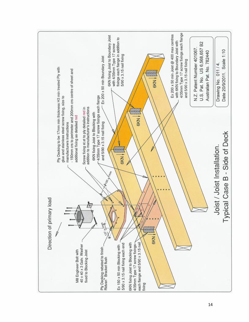
6KN Lumberlock plate with 4/35mm type 17 screw fixing to each flange as per drawing 011/3, page 13 of this document, fixing joist to boundary joist, and nogs to outside joist as per drawing 011/4, page 14 of this document.
P.V.C. Tape to prevent contact of dissimilar metals between, the balustrade base and Ridvan™ Bracket.
Suitable membranes for use with the Ridvan™ Bracket are stated in Table 1.
Manufacturer Product Notes
Polymer Developments Ltd Vulkem 350/351
Polymer Developments Ltd Vulkem 450/451
Hitchins Traffigard 300gm Fibre Glass, chopped strand mat, reinforcement
Nuplex Elasto Deck 5000 HT
Skellerup Butylclad With manufacturers adhesive as primer for areas in contact with epoxy
Skellerup Dec-king With manufacturers adhesive as primer for areas in contact with epoxy
Wetseal Purecoat
Fosroc Dekcladd 300gm Fibre Glass, chopped strand mat, reinforcement
Fosroc Dekcladd Non-woven polyester sheet reinforcement by Fosroc
Fosroc Proofex Torchseal
Table 1.
ALL membranes are to be installed in accordance with the manufacturer’s instructions. Note: the appraisal covers the joint between the selected membrane and the Ridvan™ Bracket System
only, and not the use of the membrane in any other application.
7
System Specifications
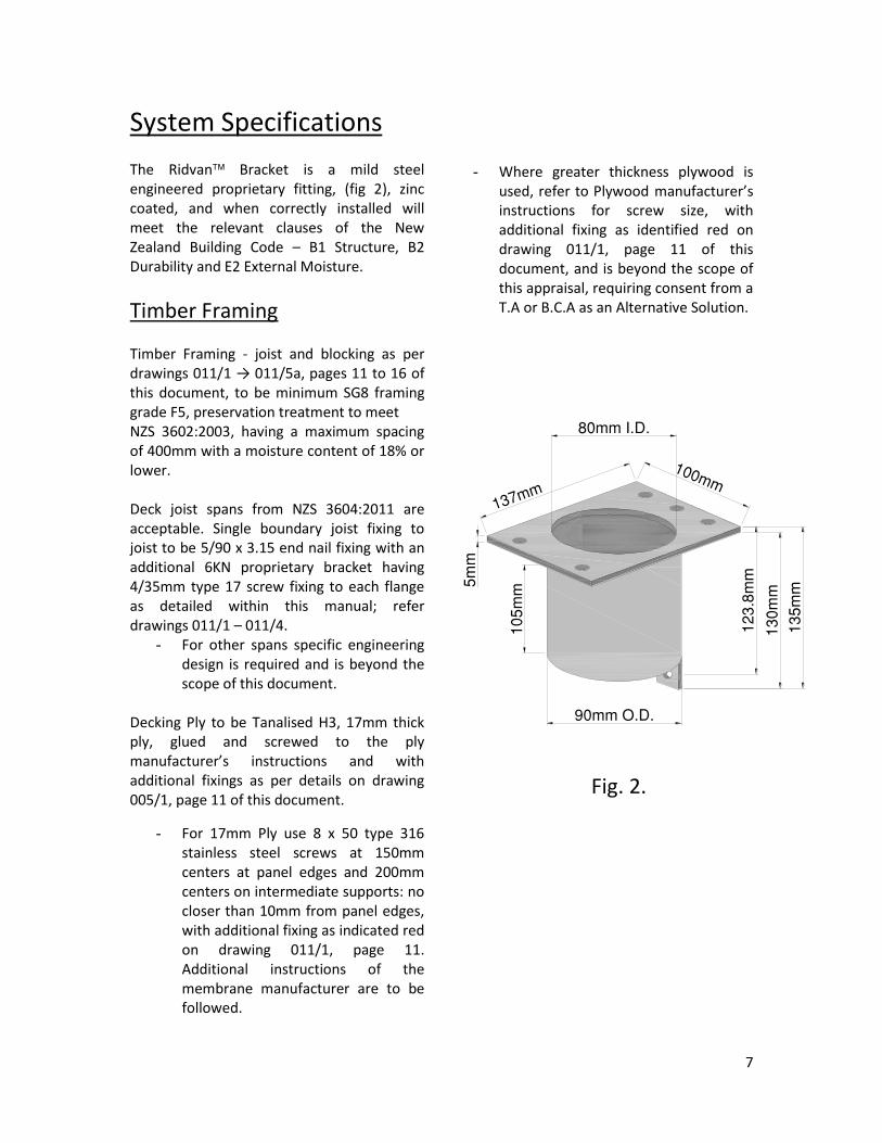
The Ridvan Bracket is a mild steel engineered proprietary fitting, (fig 2), zinc coated, and when correctly installed will meet the relevant clauses of the New Zealand Building Code – B1 Structure, B2 Durability and E2 External Moisture.
Timber Framing Timber Framing - joist and blocking as per drawings 011/1 → 011/5a, pages 11 to 16 of this document, to be minimum SG8 framing grade F5, preservation treatment to meet NZS 3602:2003, having a maximum spacing of 400mm with a moisture content of 18% or lower. Deck joist spans from NZS 3604:2011 are acceptable. Single boundary joist fixing to joist to be 5/90 x 3.15 end nail fixing with an additional 6KN proprietary bracket having 4/35mm type 17 screw fixing to each flange as detailed within this manual; refer drawings 011/1 – 011/4.
- For other spans specific engineering design is required and is beyond the scope of this document.
Decking Ply to be Tanalised H3, 17mm thick ply, glued and screwed to the ply manufacturer’s instructions and with additional fixings as per details on drawing 005/1, page 11 of this document.
- For 17mm Ply use 8 x 50 type 316 stainless steel screws at 150mm centers at panel edges and 200mm centers on intermediate supports: no closer than 10mm from panel edges, with additional fixing as indicated red on drawing 011/1, page 11. Additional instructions of the membrane manufacturer are to be followed.
- Where greater thickness plywood is used, refer to Plywood manufacturer’s instructions for screw size, with additional fixing as identified red on drawing 011/1, page 11 of this document, and is beyond the scope of this appraisal, requiring consent from a T.A or B.C.A as an Alternative Solution.
Fig. 2.

8
Corrosion Protection
The standard Ridvan Bracket is zinc coated to a minimum of 5 microns for use in “closed” environments. Where located in “sheltered” or “exposed”
positions, the Ridvan Bracket shall be of Stainless Steel construction in accordance with Table 2, are beyond the scope of the appraisal, and must be consented by a T.A. or B.C.A. as an alternative solution.
Table 2.
All 316 Stainless Steel To BS 316L The standard mild steel, zinc coated,
Ridvan Bracket is to be enclosed within 6 months of initial installation.
Where the Ridvan Bracket is of stainless steel, the bottom M8 bolt, washer and nut must also be of stainless steel, is beyond the scope of the appraisal, and must be consented by a T.A. or B.C.A. as an alternative solution. “Closed”, “Sheltered” and “Exposed” are as defined within the N.Z.B.C. Approved Documents.
Maintenance Statement Failure to comply with the requirements of this Maintenance Statement voids any and all warranties, both expressed and implied.
While the Ridvan™ Bracket in its enclosed environment requires no maintenance, the external area in the immediate vicinity of the Ridvan™ Bracket requires at least 6 monthly washing. This must be conducted with the soft fan spray of a garden hose, in combination with a soft broom and mild detergent if necessary to dislodge any dirt and grime followed by thorough rinsing of the area. At no time shall a water blaster or any other pressure increasing device be used as the implied loads exceed the building envelopes Ultimate Limit State defined by AS/NZS 1170:2002 – Ultimate Limit State is defined by that Standard as “States associated with collapse”.
Closed Sheltered Exposed
Sea Spray O.K 316 Stainless Steel 316 Stainless Steel
Zone 1 O.K 316 Stainless Steel 316 Stainless Steel
Geothermal O.K 316 Stainless Steel 316 Stainless Steel
Zones 2 & 3 O.K 316 Stainless Steel 316 Stainless Steel

9
Installation Instructions
The Ridvan Bracket is supplied with zinc coating, 5 Hylton Parker 10/12 50mm Type 17 screws, one Galvanised M8 Engineers Bolt, with one 40 x 40 x 3 Galvanised Washer and is intended for installation as follows, in conjunction with diagrams 011/1 to 011/5a of this document.
1. Install flush with Decking Ply surface,
or in the case of a solid handrail detail, directly to the top plate, using the 10/12 50mm Type 17 Screws provided, and the M8 Engineers Bolt to the bottom flange, which shall not be installed in obvious contact to knots in timber.
2. The waterproof membrane selected by the decking designer is then applied from the decking ply, across
the Ridvan Bracket, and into the cavity of the bracket, adhering to the inside to a minimum depth of 30mm - refer to drawing 011/2 - page 12. Note: the appraisal covers the joint between the selected membrane and
the Ridvan Bracket system only, and not the use of the membrane in any other application.
3. In the case of an enclosed balustrade, with decorative feature rail, the waterproof membrane selected by the balustrade designer runs from 30mm within the cavity of the bracket, up, across, and down the vertical face of the exterior cladding a minimum of 100mm. Cladding and membrane details are to comply with E2/AS1 and cladding manufacturer’s instructions - refer to drawing 011/5a - page 16.
4. The base of the baluster is then taped off, so the two, possibly different metals, are not in contact. The baluster is now placed in position, plumbed and supported as necessary. A gap between the baluster and the inside of the Ridvan™ Bracket of 5mm minimum must be maintained to allow complete encapsulation of the baluster and complete sealing of the selected membrane.

10
5. Concrete Plus LV Liquid Epoxy, (a high strength, low viscosity, unfilled epoxy) or Nitrofill LV (a low viscosity dual cartridge epoxy) shall then be applied into the recess between the Ridvan™ Bracket and the baluster, to within 3mm of the surface, permanently fixing the handrail baluster, of any shape, in place and seals the edge of the waterproof membrane.
6. In the case of an enclosed balustrade with a feature rail, the exterior plaster / cladding system is then completed in accordance with the manufacturer’s instructions and the details of E2/AS1.
7. For aesthetic purposes, a colour matched bead of M.S. Silicon may be applied between the baluster and membrane, or an additional layer of membrane applied. Water must be able to drain from the baluster onto
the decking membrane without ponding.
Feature stainless steel balustrade installed into an elevated deck with rooms below, using Ridvan™ Bracket System.
Feature glass handrail support installed into an elevated deck with rooms below, using Ridvan™ Bracket System.

11

12

13
14

15

16

17

18
Features and Benefits
N.Z Pat. No. 401067 U.S Pat. No. US 6,568,657 B2 Australian Pat. No. 782440
Quick and easy to install
Accommodates variable centres of baluster up to 1.6m - (0.75KN/M loading, total load 1.92KN ULS)
Meets or exceeds the design criteria in AS/NZS1170.1:2002, Table 3.3 – A, B, C3, and E.
Easy for membrane applicators
Confirmed structural strength as anchorage for baluster
Triple waterproof system for penetrating deck membranes
Balustrade loads are transferred directly to the joist, therefore requiring only a single boundary joist with fixings to joists of 5/90 x 3.15 end nail and a single 6KN proprietary bracket with 4/35mm type 17 screw fixing to each flange
Documentation downloadable from www.Ridvan.co.nz
Engineering Endorsement Quote: “We believe your bracket will gain acceptance in the architectural community – because there is no other practical equivalent alternative.”
- Roy G Taylor Director of Engineer Roy Taylor Engineer Limited Civil and Structural Engineer Khandallah, Wellington, New Zealand
The Ridvan™ Bracket System has an Engineering Appraisal and Certification from Roy Taylor Engineer Limited.