richton park community center: a case study in loadbearing ... · pdf filerichton park...
TRANSCRIPT

RICHTON PARK COMMUNITY CENTER: A CASE STUDY IN LOADBEARING AAC
Scott Conwell, AIA, CSI, CDT, LEED AP BD+C1
Abstract
1 Director, International Masonry Institute, Illinois Office, 2140 W. Corporate Drive, Addison, IL, 60101, USA,
This case study of the new Richton Park (Illinois) Community Center will document the first use of loadbearing AAC in the metropolitan Chicago area. It will look at how loadbearing AAC satisfied the client's criteria, and how installer certification training and an aggressive quality control plan satisfied the A/E's requirements for contractor selection. It will also take a close look at the masonry wall construction, especially the 30-ft (9.14 m) high, 12-in. (300 mm) thick loadbearing AAC gymnasium walls. This case study will make extensive
use of photographs and illustrations to show special conditions of construction such as placement of grout and reinforcement, truss bearing conditions, cast in place AAC bond beams and lintels, thinset mortar application, movement joints, and cold weather precautions. It will document the unique interface between the masonry and electrical trades, as well as the architectural detailing of the AAC. The paper will also examine the acrylic polymer Direct Applied Exterior Finish System (DEFS) used to coat the AAC. Keywords: Loadbearing, AAC, Autoclaved, Aerated, Richton Park
Figure 1. Aerial view of the loadbearing AAC Richton Park Community Center.

Autoclaved Aerated Concrete (AAC) AAC Autoclaved Aerated Concrete (AAC) is a lightweight precast concrete masonry material with exceptional structural, thermal, acoustic, and fire-resistive characteristics, making it an ideal building material for many applications. Worldwide, AAC is a very common building material for commercial and residential structures; however, owing to the small number of manufacturing facilities in the United States, its use in this country has been largely concentrated in the Southeast, proximate to the two domestic manufacturers: Aercon Florida in Haines City, Florida, and Xella Aircrete North America in Smyrna, Georgia. There are some AAC projects in all regions of the United States thanks to visionary owners, architects, and engineers already familiar with the benefits and economy offered by this material. In recent years, the merits of AAC and its inclusion in the Building Codes2 have resulted in more widespread use in the United States. History of AAC in Chicago In the past fifteen years in the Chicago, Illinois market, i.e. City and suburbs, AAC has enjoyed a small but loyal following. AAC has been used as a backing material for brick veneer high-end private residences, banks, and other commercial buildings. In the residential building boom of the early 2000’s, several large suburban homebuilders used thin AAC panels sandwiched between wood stud walls in multifamily housing demising walls, taking advantage only of the AAC’s fire resistive properties. One large development in downtown Chicago, Lakeshore East3, has used AAC block as infill within a concrete frame for fire-rated walls at the parking garage levels of at least six high-rise buildings built between 2005 and 2009. In addition to the applications of veneer backing and fire-rated partitions, there are two market areas that represent great potential for AAC masonry: shaft wall construction and loadbearing masonry construction. For whatever reason, Chicago has not seen many AAC shaft walls to date, and until 2010, there had not been a major project designed with loadbearing AAC. The Richton Park Community Center in the southern Chicago suburb of Richton Park, Illinois, has the distinction of being Chicago’s first loadbearing AAC building. Based on the project’s efficient and economic construction and anticipated performance, it will surely not be the last.
2 MSJC 2008
3 Magellan 2010
Figure 2. Aqua at Lakeshore East in Chicago uses AAC fire-rated walls at the parking levels.

Richton Park Community Center Project Team The Owner is the Village of Richton Park. The Architect/Engineer was Globetrotters Engineering Corporation. The General Contractor was Skender Construction. The Mason Contractor was Rasco Masonry. The Bricklayers were members of International Union of Bricklayers and Allied Craftworkers (BAC) Local 21. The exterior and interior finishes were applied by J.P. Phillips & Company and plasterers from BAC Local 21. AAC certification and quality control was provided by International Masonry Institute (IMI).
Design Project Requirements The program called for a 14,000 s.f. (1,300 sq. m) community center addition to the existing Village Hall, a brick and block building constructed in 1976-1979, which also houses the city’s Fire, Police, and Building departments. The addition was to be a single story building housing Park District offices, community and recreation space, and a column-free gymnasium of 30-ft (9.14 m) high walls. The west portion of the addition was to be designed to accommodate a future second floor. According to T. Abraham Lentner, Richton Park’s Director of Economic Development, the Village required low initial and life cycle costs without giving up aesthetics, durability, low maintenance, and environmental stewardship4. The Architect carefully considered this criteria, and recommended loadbearing AAC masonry with an acrylic polymer DEFS coating simulating face brick. Building Envelope Material Selection According to Margaret Lehto, AIA, LEED AP, Director of Design with Globetrotters Engineering Corporation5, the A/E first considered a structural steel frame building with brick and block cavity wall construction. As Globetrotters compared the initial cost of that system against the initial cost of a loadbearing AAC masonry system, they determined that loadbearing AAC would provide the owner with over $60,000 initial cost savings, much of that
4 Lentner 2010
5 Lehto 2010
Figure 3. 14,000 s.f. (1,300 sq. m) addition with loadbearing AAC walls

coming from eliminating the structural steel. AAC walls also provided a good substrate for a direct applied plaster finish much more durable than gypsum wallboard. Another major factor was the inherent energy efficiency and thermal storage qualities typical of AAC masonry, expecting to yield reduced energy costs. According to the Owner, these potential benefits far outweighed the risks associated with building a wall system that was new to the Chicago construction market. The A/E approved the use of AAC blocks of strength class AAC-46, having average minimum compressive strength of 580 psi (4.0 Mpa). The blocks used were rectangular prisms nominally 24-in. (600 mm) long x 8-in. (200 mm) high x 8-in. (200 mm) or 12-in. (300 mm) thick. Each block had one 4-in (100 mm) diameter core to accept vertical reinforcement and grout, spaced 24-in. (600 mm) on center. Structural System
The structural system is made up of solid or solidly grouted AAC masonry bearing walls. The AAC’s vertical reinforcing and reinforced bond beams and lintels provide necessary rigidity for transferring gravity and lateral forces to the foundation. The bearing plates for the roof joists were embedded into the AAC bond beams, which act as lateral load transfer elements of the loadbearing AAC. According to the Engineer, an added advantage of the lightweight AAC was the minimal load it transferred to the foundation. The metal roof deck is supported by open web steel joists bearing on the AAC walls. The steel joists at the gymnasium are 36-in. (915 mm) deep spanning 70-ft. (21 m), spaced at 5-ft. (1,500 mm) on center. There are no structural steel or concrete support columns, as the AAC is the only means of support for the steel joists. The metal roof deck acts as a diaphragm to transfer lateral loads to the AAC block walls.
Movement Control Due to the autoclaving process during manufacture and the monolithic nature of the wall, AAC is generally recognized as a dimensionally stable material, with an average drying shrinkage of less than .02% 5. According to AAC manufacturer Xella Aircrete North America, the expected movement of the material due to thermal and moisture changes would be negligible. 7 However, the Architect decided to take a conservative approach and specify vertical control joints approximately 24 ft. (7 m) on center. Careful coordination was required
6 ASTM C 1386 - 07
7 Xella 2010
Figure 4. AAC bond beams provide rigidity to transfer lateral and gravity loads.

between the vertical control joint spacing and the module of the brick template to ensure that each control joint was projected out to coincide with a simulated head joint in the finish. Moisture Control The solid exterior AAC walls with DEFS coatings were designed as barrier walls. The solid nature of the walls and their water-resistant coatings were designed to prevent moisture infiltration, and therefore flashing and weeps were neither required nor installed, except at the top of the wall. All the lintels above perimeter door and window openings were cast-in-place AAC masonry lintels, not steel angles, and therefore did not require flashing. Energy Efficiency The Owner wanted to take every practical measure to build an environmentally responsible building, while choosing to avoid the costly LEED certification process. Of paramount importance was the energy efficiency of the building envelope. AAC provides thermal benefits in two distinct ways: it has a high thermal resistance (R-value), and it has great thermal mass, or heat storage capacity. The steady-state R-value of the AAC 4 density AAC used on this project is 1.25 per inch of thickness. Therefore, the 8-in. (200 mm) AAC walls were R-10, and the 12-in. (300 mm) AAC walls were R-15, irrespective of the DEFS coating. In addition to R-value, thermal storage was also considered when figuring the energy efficiency of the wall. Thermal storage is the temporary storage of high or low temperature energy for later use, allowing a time gap between energy use and availability (Fig. 3). Because AAC has a mass greater than 30 lb/ft2 (150 kg/m2), it is considered a mass wall8, and its steady state R-value may therefore be adjusted upward by a multiplier known as Dynamic Benefit for Massive Systems, or DBMS,9 giving a more accurate depiction of the thermal performance of a mass wall. During design, Xella provided the A/E with an estimated DBMS of 1.48. Effectively, this gave the 8-in. (200 mm) and 12-in. (300 mm) AAC walls DBMS-adjusted R-values of R-14.8 and R-22 respectively. Ideally, the mechanical engineer would use the DBMS-adjusted R-values when sizing the HVAC equipment, resulting in further cost savings. 10
8 IECC 2009
9 Kosny 1999
10 NCMA 2008
Figure 5. Illustration of the damping benefit of massive AAC walls.10

Pre-Construction Contractor Qualifications Because AAC construction requires workmanship techniques that vary from traditional masonry construction, it is imperative that the work be done by a qualified mason contractor using bricklayers trained in AAC construction. In the initial specifications, the A/E required that the AAC installer have a minimum of five years experience in the construction of structural AAC. Since this was the first project of its type in Chicago, no local contractor met this requirement. With the input of the International Masonry Institute (IMI) 11, the GC recommended that the Architect substitute a more realistic yet equally rigid requirement: “AAC installers to be certified in AAC construction by the International Masonry Institute.” 12 Installer Certification The International Masonry Institute (IMI) is the organization that conducts the apprenticeship and training function for the International Union of Bricklayers and Allied Craftworkers (BAC) and their signatory contractors. IMI had been delivering AAC training and certification in Chicago and nationwide since the late 1990s, and continues to do so.13 The GC took bids from a number of AAC-certified mason contractors, and selected Rasco Masonry for the work. Quality Control Requirements In another effort to maximize the construction quality of the AAC, the GC arranged for IMI to provide Quality Control services throughout the duration of AAC construction. This required IMI staff architects, engineers, and technical representatives to review masonry plans, specifications, and submittals; to help identify and interpret ASTM standards and building code requirements; and to make periodic visits to the jobsite and generate field reports. Quality Control observations included items such as compliance with cold weather construction requirements, rebar lap splice lengths, AAC lintel bearing lengths, thin-bed mortar coverage, and AAC surface quality. The mason contractor, the GC, the Owner and the A/E realized a great benefit to the enhanced Quality Control services provided by IMI.
11
IMI 2010 12
Skender 2010 13
IMI 200
Figure 6a. Bricklayers certified in AAC construction carry this wallet card issued by IMI.

AAC Construction Cold Weather Requirements AAC work began in Feburary 2010, therefore the mason contractor strictly adhered to cold weather masonry construction and protection procedures as outlined in the Building Code Requirements for Masonry Structures.14 The mason contractor constructed a staging enclosure large enough to stage six pallets of AAC block, sand, and water for mixing the mortar and grout. The enclosure was heated with a 300,000 BTU heater, and the temperature inside the enclosure was kept at least 60°F (16°C) during construction, and 50°F (10°C) overnight and during weekends. There was also a heated enclosure around the mixing area of the silos for the preblended mortar and grout. Insulating blankets were used to cover newly constructed walls, keeping the AAC masonry above 32°F (0°C) for the first 4 hours after thin bed mortar application, as required by the Code. Foundation Preparation and Base Course Laying up the base course was one of the most critical tasks for the bricklayers, since the base course, or leveling course, is the only course in an AAC wall that is installed in a 3/8-in. (10 mm) thick bed joint of masonry mortar. Above the leveling course, the thin-bed mortar joints do not allow for variation of thickness to compensate for slight irregularities in elevation. To prepare for a level installation, the bricklayers ground down the high areas of concrete at the top of the foundation wall. ASTM C 270 Type S mortar, 3/8-in. (10 mm) thick, was used at the leveling course. Electrical coordination was also required before the first AAC block was laid. The top of the concrete foundation wall was notched for future placement of conduit to be embedded into the AAC. The foundation was also cast with a brick ledge to allow for an anchored veneer base; though it was later decided to use a thinner adhered veneer.
14
MSJC 2008
Figure 6b. Heated enclosure for staging material.
Figure 7. Leveling course was laid in Type S mortar; top of fdtn. is notched for recessed conduit; #5 fdtn. dowels @ 24-in. o.c. line up w/ pre-cored AAC units.

Wall Construction AAC construction was straightforward and swift. The loadbearing walls incorporated #6 bars at 24-in (600 mm) o.c. as vertical reinforcement, and periodic bond beams and AAC lintels (see Figure 9). In lieu of single-course bond beams, the Engineer called for bond beams that were two courses high, since the AAC strength class was changed from AAC-6 to AAC-4 due to limited material availability. The U-block was factory-made by adhering three 2-in. (50 mm) thick pieces of AAC with the same thin-bed mortar used for construction. Fabricating the U-block units in this fashion, rather than cutting out the center portion of a solid AAC block, enabled the manufacturer to minimize waste. As typical in AAC masonry construction, the bricklayers used a notched trowel to spread the thinbed mortar on the AAC units, resulting in joints that were 1/16 to 1/8-in. (2 to 3-mm) thick. 15 Production was quick due to the larger unit size and the light weight of the units. The AAC block were 50% larger than a standard 16-in. (400 mm) concrete masonry unit. The AAC-4 units have a density of about 31 pcf (497 kg/m3) resulting in a unit weight of about 28 pounds (13 kg) per block, which is about the same as a lightweight CMU with a density of 105 pcf (1,682 kg/m3). 16 While the efficiency may not directly translate to a 50% increase in production, the mason contractor was very pleased with the rate of production. According to Rasco Masonry, it took their crew of approximately 6 bricklayers and 4 laborers about 5 weeks to complete the AAC walls which were approximately 18,000 s.f. ( 1,672 sq. m).17 Surface Preparation As they laid the AAC, the bricklayers were careful to provide a finish surface adequately smooth to receive the DEFS coating, which would be applied by the Plasterers. They applied enough mortar for full head joints and bed joints, while at the same time keeping the surface of the wall clean and smooth. Excess mortar that smeared on the surface of the AAC, if not removed at once, was later removed with a rasp. Patching small voids and chips in the AAC was also required prior to application of the DEFS. Patching was done with a proprietary AAC patching compound provided by the AAC manufacturer.
15
ASTM C 1660 - 09 16
ASTM C 90 - 09 17
Rasco 2010
Figure 8. Bricklayers use a notched trowel and thin-bed mortar to bond AAC units together.
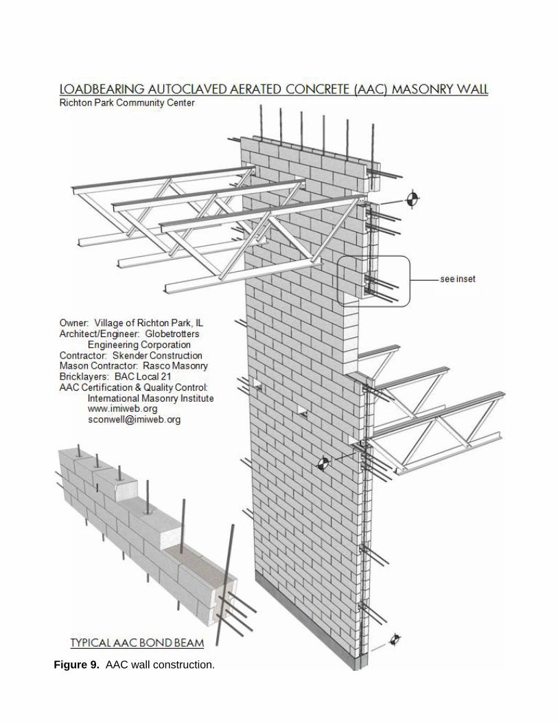
Figure 9. AAC wall construction.
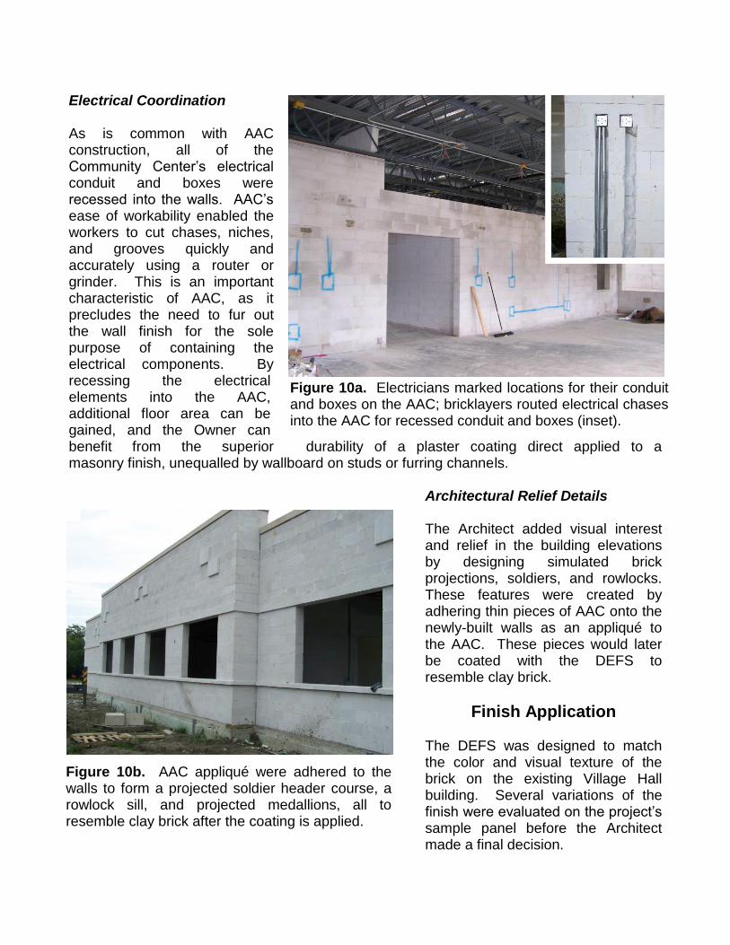
Electrical Coordination As is common with AAC construction, all of the Community Center’s electrical conduit and boxes were recessed into the walls. AAC’s ease of workability enabled the workers to cut chases, niches, and grooves quickly and accurately using a router or grinder. This is an important characteristic of AAC, as it precludes the need to fur out the wall finish for the sole purpose of containing the electrical components. By recessing the electrical elements into the AAC, additional floor area can be gained, and the Owner can benefit from the superior durability of a plaster coating direct applied to a masonry finish, unequalled by wallboard on studs or furring channels.
Architectural Relief Details The Architect added visual interest and relief in the building elevations by designing simulated brick projections, soldiers, and rowlocks. These features were created by adhering thin pieces of AAC onto the newly-built walls as an appliqué to the AAC. These pieces would later be coated with the DEFS to resemble clay brick.
Finish Application The DEFS was designed to match the color and visual texture of the brick on the existing Village Hall building. Several variations of the finish were evaluated on the project’s sample panel before the Architect made a final decision.
Figure 9. AAC wall construction
Figure 10b. AAC appliqué were adhered to the walls to form a projected soldier header course, a rowlock sill, and projected medallions, all to resemble clay brick after the coating is applied.
Figure 10a. Electricians marked locations for their conduit and boxes on the AAC; bricklayers routed electrical chases into the AAC for recessed conduit and boxes (inset).
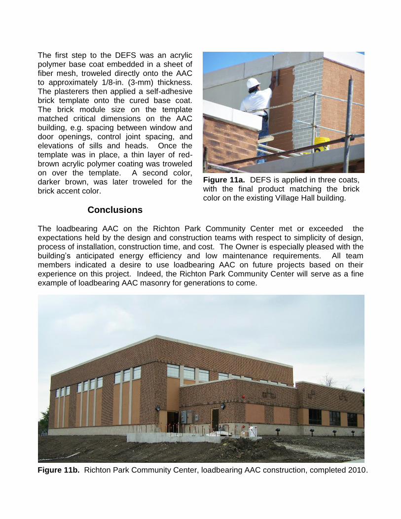
The first step to the DEFS was an acrylic polymer base coat embedded in a sheet of fiber mesh, troweled directly onto the AAC to approximately 1/8-in. (3-mm) thickness. The plasterers then applied a self-adhesive brick template onto the cured base coat. The brick module size on the template matched critical dimensions on the AAC building, e.g. spacing between window and door openings, control joint spacing, and elevations of sills and heads. Once the template was in place, a thin layer of red-brown acrylic polymer coating was troweled on over the template. A second color, darker brown, was later troweled for the brick accent color.
Conclusions The loadbearing AAC on the Richton Park Community Center met or exceeded the expectations held by the design and construction teams with respect to simplicity of design, process of installation, construction time, and cost. The Owner is especially pleased with the building’s anticipated energy efficiency and low maintenance requirements. All team members indicated a desire to use loadbearing AAC on future projects based on their experience on this project. Indeed, the Richton Park Community Center will serve as a fine example of loadbearing AAC masonry for generations to come.
Figure 11b. Richton Park Community Center, loadbearing AAC construction, completed 2010.
Figure 11a. DEFS is applied in three coats, with the final product matching the brick color on the existing Village Hall building.

References
ASTM C 1386 – 07: “Standard Specification for Precast Autoclaved Aerated Concrete (AAC) Wall Construction Units,” ASTM International, www.astm.org, West Conshohocken, Pennsylvania, 2007.
ASTM C 1660 – 09: “Standard Specification for Thin-bed Mortar for Autoclaved Aerated Concrete (AAC) Masonry,” ASTM International, www.astm.org, West Conshohocken, Pennsylvania, 2009.
ASTM C 90 – 09: “Standard Specification for Loadbearing Concrete Masonry Units,” ASTM International, www.astm.org, West Conshohocken, Pennsylvania, 2009.
BAC 2010: International Union of Bricklayers and Allied Craftworkers, Washington D.C., www.bacweb.org, 2010.
IECC 2009: 2009 International Energy Conservation Code and ANSI/ASHRAE/IESNA Standard 90.1-2007 Energy Standard for Buildings Except Low-Rise Residential Buildings, ICC, www.iccsafe.org, Washington D.C., 2009.
IMI 2010: International Masonry Institute, Annapolis, MD, www.imiweb.org, 2010.
Kosny 1999: Kosny, Jan, “New Value for High-Mass Walls,” Home Energy Magazine Online, www.homeenergy.org, Sept/Oct 1999.
Lehto 2010: Lehto, Margaret, Globetrotters Engineering Corporation, www.gec-group.com, Chicago, Illinois, 2010.
Lentner 2010: Lentner, T. Abraham, Village of Richton Park, www.richtonpark.org, Richton Park, Illinois, 2010.
Magellan 2010: Magellan Development, www.magellandevelopment.com, Chicago, Illinois
MSJC 2008: Building Code Requirements for Masonry Structures (TMS 402-08/ACI 530.1-08/ASCE 5-08) and Specification for Masonry Structures (TMS 602-08/ACI 530.1-08/ASCE 6-08)
NCMA 2008: National Concrete Masonry Association, “Masonry Thermal Performance,” Concrete Masonry Designs, Herndon, Virginia, 2008.
Rasco 2010: Rasco Masonry, Prairie View, Illinois, 2010.
Skender 2010: Skender Construction, www.skender.com, Chicago, Illinois, 2010.
Xella 2010: Xella Aircrete North America, www.xella-usa.com, Adel Georgia, 2010.