ri h drichard gill - yclf · electrokinetic enhanced bioremediation of organic contaminants in...
TRANSCRIPT

Electrokinetic enhanced bioremediation of organic
contaminants in groundwatercontaminants in groundwater
Ri h d GillRichard Gill([email protected])
Dr Steve ThorntonDr Mike Harbottle (Cardiff University)Dr Mike Harbottle (Cardiff University)
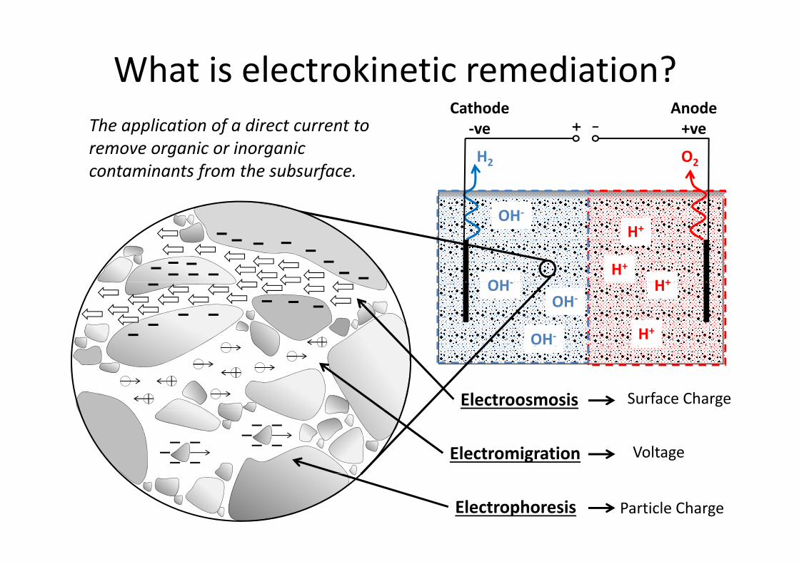
What is electrokinetic remediation?The application of a direct current to remove organic or inorganic H O
Cathode‐ve
Anode+ve
e o e o ga c o o ga ccontaminants from the subsurface.
OH‐
H2 O2
H+
H+
H+
OH
OH H+
H+OH‐
OH‐OH‐
Electroosmosis Surface Charge
Electromigration Voltage
Electrophoresis Particle Charge

How can EK enhance bioremediation?Cathode
‐veAnode+veTransformation of contaminants by
microorganisms into less harmful c oo ga s s to ess a fusubstances
Enhanced Growth
EK‐BIO function
AvailabilityFactors
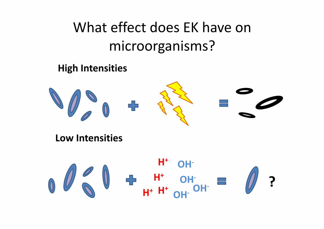
What effect does EK have on microorganisms?
High Intensities
Low Intensities
H+ OH‐
Low Intensities
?H+
H+H+OH‐
OH
OH‐OHHH OH‐

How can EK be applied?How can EK be applied?Cathode Anode
AmendmentBiological +h lChemical Tank
Energy Example3 month field trial
1500 kWh14.5 p kWh‐1
Suni, S., Malinen, E., & Kosonen, J. (2007). Journal of Environmental Science and Health Part A, 42, 257–267.

Example of field applicationExample of field applicationEK Bio‐fence
PCE PCERemediation of VOCs
Groundwater Flow
Treatment Wells
Cathode Anode+ e‐ve +ve
Godschalk and Lageman, 2005Engineering Geology, 77, 3‐4, 225‐231

Conceptual Model and Project PremiseConceptual Model and Project Premise
Amendment
Effective Ionic
MobilitySolute
ConcentrationElectric Field Enhanced
ElectroosmoticFlow
Electrical Conductivity
Electromigrationy Concentration Enhanced
Biodegradation

Conceptual Model to Experimental Design
Cathode Anode
NO3‐
TolueneToluene

Experimental SetupExperimental SetupCathode Anode
Reservoir T k
Power Supply Cathode AnodeTankSupply
Experiment Aim:Experiment Aim:• Test setup• Migrate NO3‐ across system through glass beadssystem through glass beads• Compare against calculated values

Preliminary ResultsPreliminary ResultsCalculated Observed
900 100%900
80%
100%
700
800
80%
90%
700
800
(%)
ass (mg)
60%
80%
500
60060%
70%
500
600
Total
Nitrate Ma
40%300
400
500
40%
50%
300
400
500
N
20%
100
200
300
20%
30%
100
200
300
0%0
100
0 20 40 60 800%
10%
0
100
0 20 40 60 80
Time (hours) Time (hours)

Preliminary ResultsPreliminary ResultsNO3
‐ movement NO3‐ movement
Calculated Observed
100
120
100
120NO3 movement
Cathod
e
Anod
e
Cathod
e
Anod
e
80 80
100C C
mg L‐1)
60 60
Nitrate (m
20
40
20
40
N
0
20
0 0 0 2 0 4 0 6 0 8 1 00
20
0 0 0 2 0 4 0 6 0 8 1 00.0 0.2 0.4 0.6 0.8 1.0 0.0 0.2 0.4 0.6 0.8 1.0Normalised Distance from Cathode Normalised Distance from Cathode
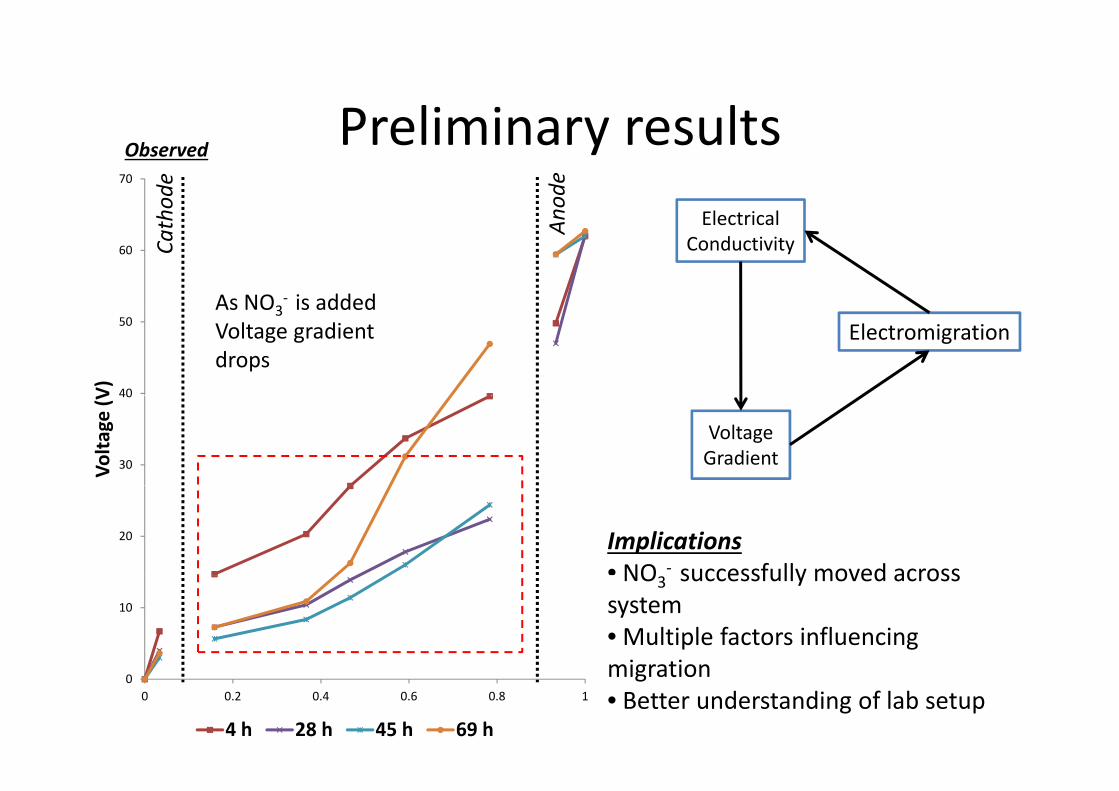
Preliminary resultsPreliminary results70
Electricalhode
node
Observed
60
Electrical Conductivity
As NO3‐ is added
Cath An
40
50
V)
ElectromigrationAs NO3 is added Voltage gradient drops
30
40
Volta
ge (V
Voltage Gradient
20 Implications• NO ‐ successfully moved across
10
NO3 successfully moved across system• Multiple factors influencing migration0
0 0.2 0.4 0.6 0.8 1
4 h 28 h 45 h 69 h
migration• Better understanding of lab setup

Conclusions and Future WorkConclusions and Future WorkEK t ti l t h bi di ti• EK potential to enhance bioremediation
• Application in physically heterogeneous settings require further investigation:g
Details• Influence of physical heterogeneity represented by1 Influence of physical heterogeneity represented by spatially variable K on NO3
‐migration• V gradient and NO3
‐ concentration on penetration
1
• Influence of physical heterogeneity on EK‐biostimulation
2
• V gradient and NO3‐ concentration on penetration
and degradationl• Processes in two‐dimensional system
• Couple with modelling3