rhinocam-mill 2019 quick start guide start guides for each rhinocam module are available in both pdf...
TRANSCRIPT

Quick StartGuide
Published: December 2018
for RhinoCAM-MILL 2019
MecSoft Corpotation© Copyright 1998-2018

RhinoCAM-MILL 2019 Quick Start Guide
by MecSoft Corporation
________________________________________________________________________________________________________________________________________________________________________________________________________________________________________________________________________________________________________________________________________________________________________________________________________________________________________________________________________________________________________________________________________________________________________________________________________________________________________________________________
User Notes:
2Contents
2
© MecSoft Corporation
Table of Contents
Useful Tips 4
What's New 5
Videos & Guides 6
Print Media Archive 8
About this Guide 9
................................................................................................................................... 91 About the MILL Module
................................................................................................................................... 92 Using this Guide
Getting Ready 11
................................................................................................................................... 111 Running RhinoCAM
................................................................................................................................... 112 About the RhinoCAM Display
................................................................................................................................... 123 Load the MILL Module
................................................................................................................................... 154 Load the Part Model
................................................................................................................................... 175 Machining Strategy
................................................................................................................................... 186 Main Programming Steps
................................................................................................................................... 187 Define the Machine Tool
................................................................................................................................... 198 Select the Post Processor
The Setup 22
................................................................................................................................... 221 Machining Setup - Skip if in STD or EXP Configuration
................................................................................................................................... 222 Create Stock Geometry
................................................................................................................................... 253 Align Part and Stock
................................................................................................................................... 284 Specify Material
................................................................................................................................... 305 Set Work Coord Sys (Work Zero)
Create Tools 36
Machine the Inner Profiles 42
................................................................................................................................... 431 Control Geometry
................................................................................................................................... 452 Cutting Tool
................................................................................................................................... 463 Feeds and Speeds
................................................................................................................................... 474 Clearance Parameters
................................................................................................................................... 495 Cut Parameters

RhinoCAM-MILL 2019 Quick Start Guide3
© MecSoft Corporation
................................................................................................................................... 506 Cut Level Parameters
................................................................................................................................... 517 Entry/Exit Parameters
................................................................................................................................... 538 Cut Material Simulation
Machine the Outer Profile 59
Post G-Code 65
Generate Reports 68
................................................................................................................................... 681 Information Report
................................................................................................................................... 692 Shop Documentation
Where to go for more help 72
Index 74

Useful Tips 4
© MecSoft Corporation
Useful Tips
Here are some useful tips that will help you use this guide effectively.
1. For purposes of brevity, Rhino refers to both Rhinoceros 5 or Rhino 6.
2. Copy the tutorial files to a location other than the installation folder to make sure youhave read/write privileges to the files.
3. Once you start working with the tutorial file, save your work periodically!
4. Don’t stress out too much if you are having trouble with the tutorial. Call us or send usemail and we can help you out.
5. Most of all have fun!

RhinoCAM-MILL 2019 Quick Start Guide5
© MecSoft Corporation
What's New
You can find out What's New in the latest release of RhinoCAM here:
Related Topics
What's New in RhinoCAM 2019
Watch the What's New in 2019 Webinar!

Videos & Guides 6
© MecSoft Corporation
Videos & Guides
Quick Start Guides for each RhinoCAM module are available in both PDF and Video format. Refer to the following information to access these guides:
Quick Start Guide Videos
RhinoCAM 2019 Automatic Feature Machining (AFM) Quick Start
RhinoCAM 2019 Mill Quick Start
RhinoCAM 2019 TURN Quick Start
RhinoART 2019 Quick Start
RhinoCAM-MESH 2019 Quick Start
RhinoCAM 2019 True Shape Nesting Quick Start
RhinoCAM 2019 Rectangular Nesting Quick Start
RhinoCAM 2019, 2½ Axis Introduction
RhinoCAM 2019, 3 Axis Introduction
RhinoCAM 2019, 4 Axis Introduction
The Complete Video Play List
Here is a link to the complete 2019 Video Play List
How to Access the Quick Start Guide Documents
To help you quickly get started in working with each module, select one of the Helpfiles located on the RhinoCAM Learning Resources dialog.
You will find:
· Data Sheets
· Quick Start Guides
· What's New documents
· Online Help links
The Quick Start Guides will help you step through an example tutorial which willillustrate how to use the module. To access the Learning Resources dialog:
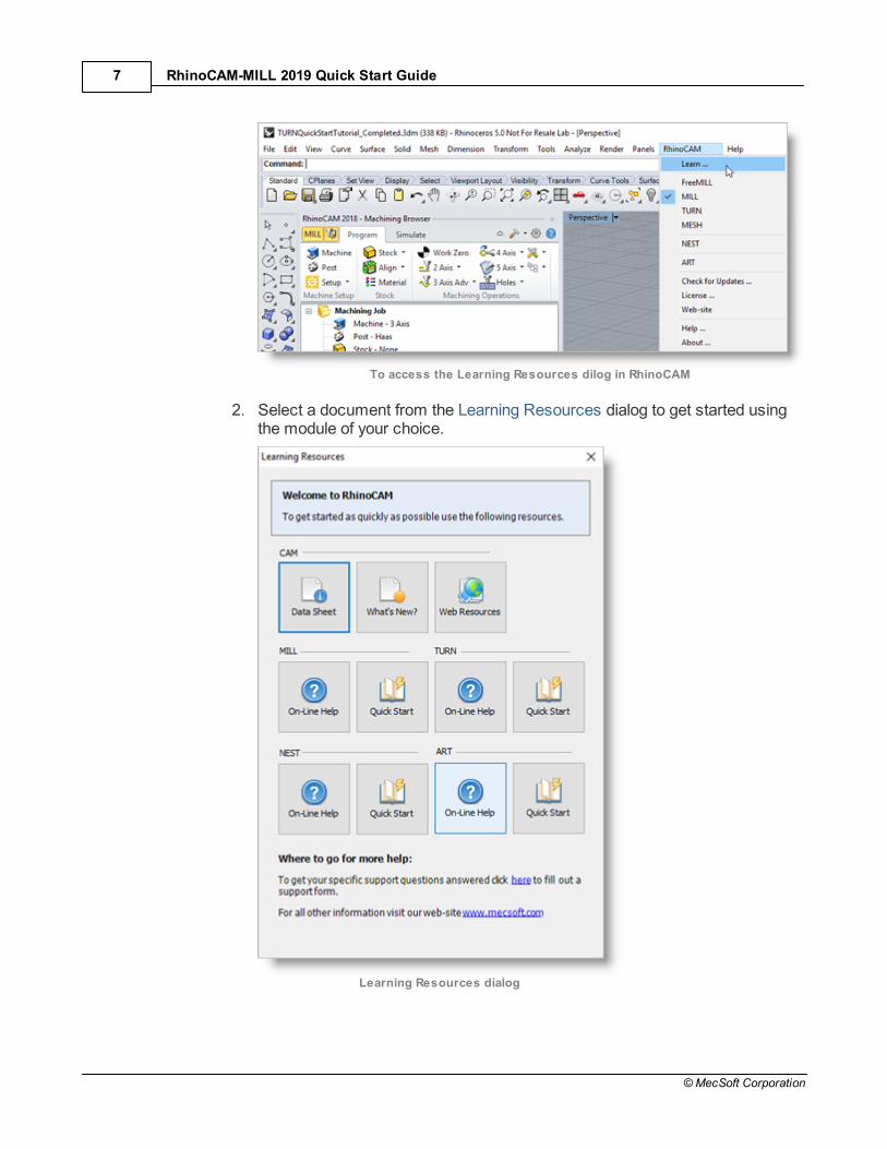
1. From the Rhino Main Menu, drop down the Main menu and select Learn ...
RhinoCAM-MILL 2019 Quick Start Guide7
© MecSoft Corporation
To access the Learning Resources dilog in RhinoCAM
2. Select a document from the Learning Resources dialog to get started usingthe module of your choice.
Learning Resources dialog

Print Media Archive 8
© MecSoft Corporation
Print Media Archive
MecSoft Corporation is proud to announce our Print Media Archive where you can find everyReference Manual, Printed Guide and Video Archive on every MecSoft CAM Product. Most ofthese guides are completely FREE to download.
eBook Reference Manuals
The RhinoCAM-MILL 2019 Reference
The RhinoCAM-TURN 2019 Reference
The RhinoCAM-NEST 2019 Reference
The RhinoCAM-ART 2019 Reference
The RhinoCAM-MESH 2019 Reference
The RhinoCAM-PPG 2019 Reference
AMS Subscription Training Materials (Active AMS Subscription Required)
CAMJam 2019 Self Training Video Archive **
The 2019 Cutting Tools Workbook **
The F1 CO2 Racer Body Tutorial **
** FREE with your Annual Maintenance Subscription (AMS)

RhinoCAM-MILL 2019 Quick Start Guide9
© MecSoft Corporation
About this Guide
On-line help compiled on: Monday, December 3, 2018
5.1 About the MILL Module
The RhinoCAM MILL module offers fast gouge free solids/surface model machiningtechnology coupled with cutting simulation/verification capabilities running inside Rhino (5 or6) for programming CNC Mills. This integration allows for seamless generation of toolpath andcut material simulation/verification within Rhino, for programming milling machines thatsupport 3, 4 and 5 axis continuous machining.
The module also comes with numerous post-processors to output the programmed G-codeto some of the most popular machines on the market. A simple and well thought out userinterface makes this system one of the most intuitive and easy to use milling systemsavailable today.
You can work with the native Rhino (5 or 6) data as well as use any of the data types that canbe imported into Rhino such as solids, surfaces and meshes. Then you can use theRhinoCAM MILL module with its wide selection of tools and toolpath strategies to createmachining operations and associated toolpaths for CNC Mills. These toolpaths can then besimulated and verified, and finally post-processed to the controller of your choice.
5.2 Using this Guide
If you have installed RhinoCAM successfully on your computer and are now looking at theblank screen of Rhino and wondering what to do next, this is the guide for you. This guide will
About this Guide 10
© MecSoft Corporation
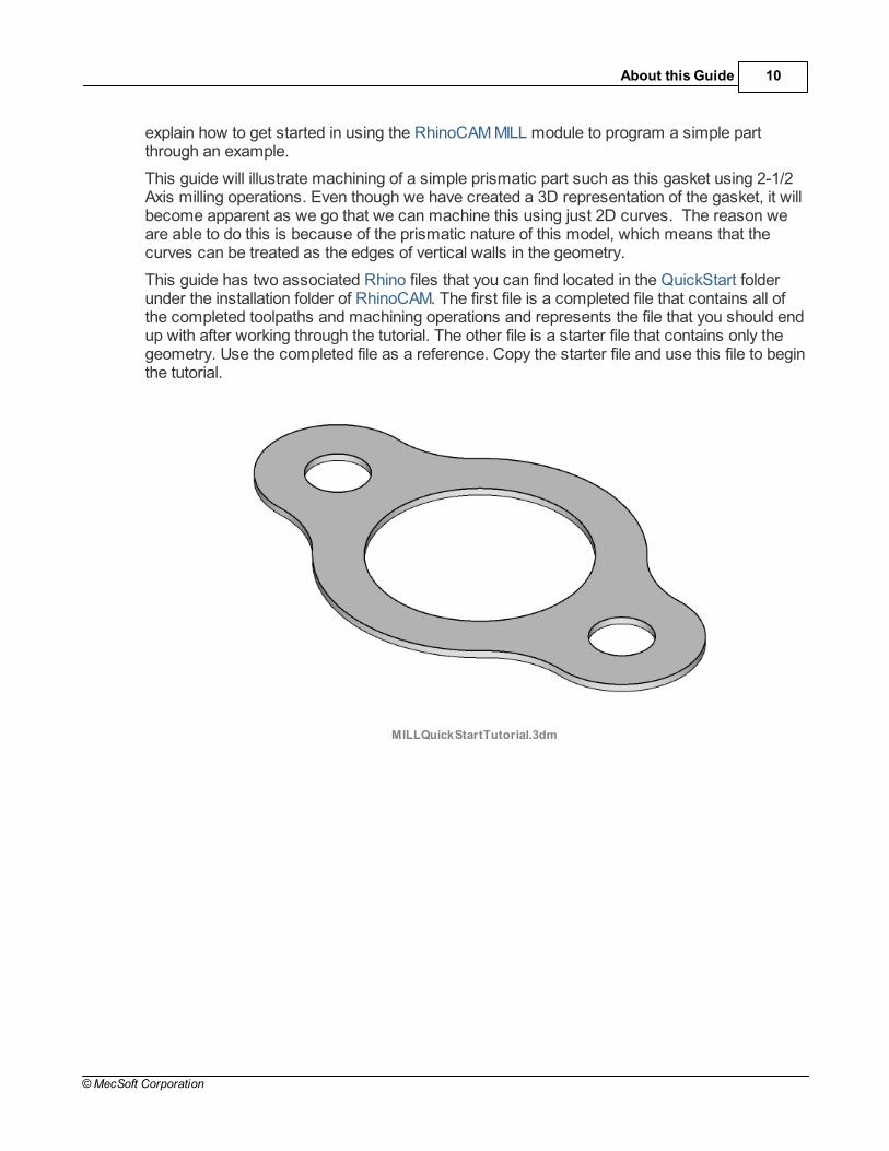
explain how to get started in using the RhinoCAM MILL module to program a simple partthrough an example.
This guide will illustrate machining of a simple prismatic part such as this gasket using 2-1/2Axis milling operations. Even though we have created a 3D representation of the gasket, it willbecome apparent as we go that we can machine this using just 2D curves. The reason weare able to do this is because of the prismatic nature of this model, which means that thecurves can be treated as the edges of vertical walls in the geometry.
This guide has two associated Rhino files that you can find located in the QuickStart folderunder the installation folder of RhinoCAM. The first file is a completed file that contains all ofthe completed toolpaths and machining operations and represents the file that you should endup with after working through the tutorial. The other file is a starter file that contains only thegeometry. Use the completed file as a reference. Copy the starter file and use this file to beginthe tutorial.
MILLQuickStartTutorial.3dm
RhinoCAM-MILL 2019 Quick Start Guide11
© MecSoft Corporation
Getting Ready
6.1 Running RhinoCAM
Locate the Rhinoceros 5 (or Rhinoceros 6) shortcut on your desktop and double click tolaunch the application.
Alternatively you can also click on the Windows Start button and select All Programs. Go tothe program group containing Rhinoceros 5 (or Rhinoceros 6). (The name of this programgroup will usually be called Rhinoceros, unless you specified otherwise during setup.)
Once you locate the program group, select it and then select Rhinoceros to launch theapplication.
If the installation was successful, upon launching of Rhino you should observe a menu entrycalled RhinoCAM 2019 in the main menu bar of Rhino.
If you do not see this menu entry then please check the On Line Help document of theproduct (found in the installation folder) for help with trouble shooting the installation.
6.2 About the RhinoCAM Display
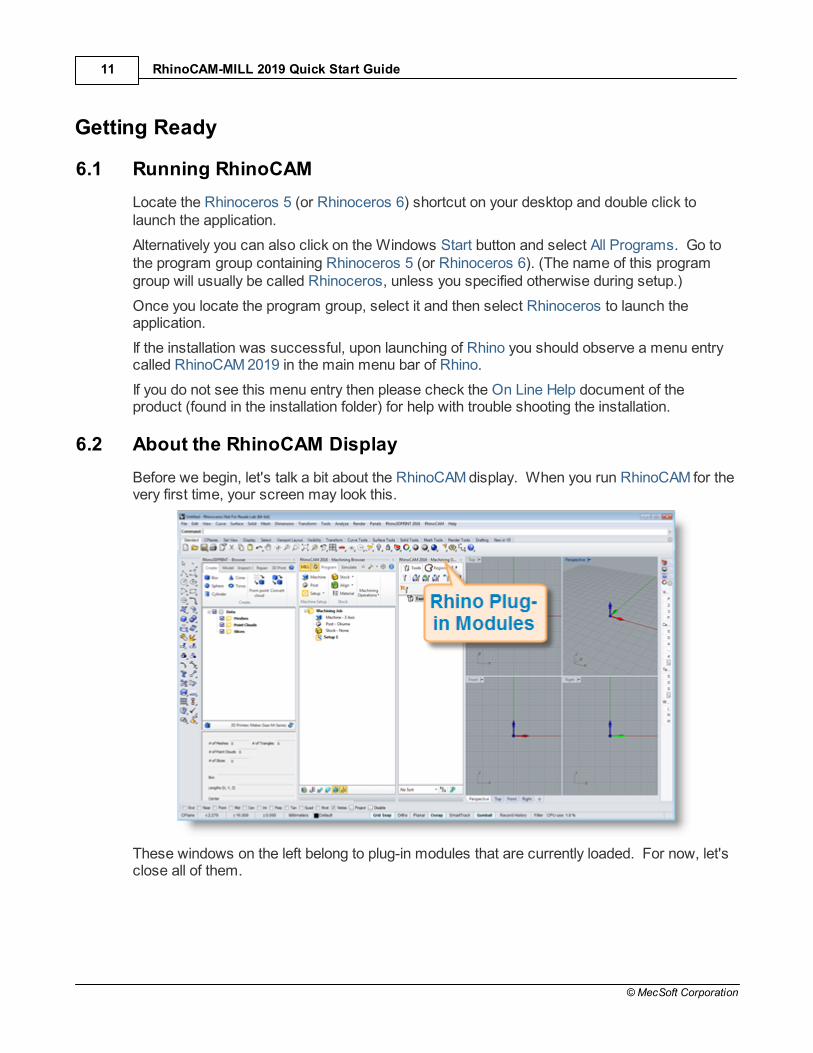
Before we begin, let's talk a bit about the RhinoCAM display. When you run RhinoCAM for thevery first time, your screen may look this.
These windows on the left belong to plug-in modules that are currently loaded. For now, let'sclose all of them.

Getting Ready 12
© MecSoft Corporation
With all plug-in modules closed your screen will look like this:
6.3 Load the MILL Module
Now, let's begin by launching the RhinoCAM MILL module.
1. From the Rhino main menu bar, you will see the RhinoCAM menu item.
2. Drop-down the menu and pick MILL to load the module.

RhinoCAM-MILL 2019 Quick Start Guide13
© MecSoft Corporation
3. Docked on the left you will see the Machining Browser and the Machining ObjectsBrowser. When you first run RhinoCAM, these two browsers my be docked side byside. However, you can move them anywhere on the screen that feels comfortable foryou.
4. For example, let's move the Machining Objects Browser so that it displays under theMachining Browser on the left. Simply left-click and hold the title bar of the browserand drag it around on your screen.

Getting Ready 14
© MecSoft Corporation
While do so you will see possible docking location highlight on the display.
5. We'll drag the Machining Objects Browser over the base of the Machining Browseruntil the cursor activates the the bottom docking location as shown below.
When the preview of the new location displays, let go of the right-mouse button andthe browser will move to that location.
6. You can also re-size the height and width of each browser making sure that all of the

RhinoCAM-MILL 2019 Quick Start Guide15
© MecSoft Corporation
command icons and menus are easily accessible.
6.4 Load the Part Model
“Part” refers to the geometry that represents the final manufactured product. You can createparts within Rhinoceros or import geometry created in another CAD system.
1. Select File / Open from the Main Menu bar, or click the Open icon from the Standardbar.
2. From the Open dialog box, select the MILLQuickStartTutorial.3dm file from the C:\ProgramData\MecSoft Corporation\RhinoCAM 2019 for Rhino x.x\QuickStart\ folder.

Getting Ready 16
© MecSoft Corporation
As mentioned before, it is advisable to make a copy of this part at a suitable alternativefolder so that you have write privileges to modify the part.
By default, the ProgramData folder is "hidden" from view. Here are thesteps to Show hidden files and folders:
1. For Windows7/8 users: Go to Control Panel > Appearance andPersonalization > Folder Options. For Windows10 users: Go to Control Panel > Appearance andPersonalization > File Explorer Options.
2. Select View tab and under advanced settings select Show Hidden files andfolders, clear the check boxes for:
· Hide extensions for known file types
· Hide protected operating system files (Recommended)
3. Click Apply and OK.
When the Load Settings from File dialog appears, pick No for this file. In the future youmay have older files whose CAM System Preferences you wish to use so leave thebox Do not display dialog again unchecked for now.
The part appears as shown below

RhinoCAM-MILL 2019 Quick Start Guide17
© MecSoft Corporation
MILLQuickStartTutorial.3dm
You can import 2D drawings, Solid, Surface and Mesh models that aresupported in Rhinoceros.
3. From the Rhino display, double-left-click on the Perspective View tab to maximize it.
6.5 Machining Strategy
Based on the type of geometry of this part, we will machine this model out of a 10 x 6 x 1/8inch poplar wood sheet. Since the part is relatively thin and prismatic, we will machine thisout by using only a single type of machining operation - 2-½ axis machining method calledProfiling. We will also use just a single 0.5 inch flat end mill for performing all machining. Wewill also assume that the wooden sheet will be held to the machine table or the spoil sheet onthe table using double-sided tape or a vacuum table requiring no clamps or fixtures.

Getting Ready 18
© MecSoft Corporation
6.6 Main Programming Steps
The following steps will be followed in machining this model. Some of these steps will have tobe performed just once and others may have to be repeated to complete the machining.
1. Define the Machine and Post-processor to use.
2. Define the Machining Setup including Stock Geometry, Material and Work Zero.
3. Create and Select a Tool to use for machining.
4. Create the Machining Operations including the Feeds and Speeds, the ClearancePlane and other Cutting Parameters.
5. Generate the toolpaths.
6. Simulate the toolpaths.
7. Post Process the toolpaths.
8. Generate Shop Documentation.
6.7 Define the Machine Tool
Let's start by defining the Machine to use for this job.
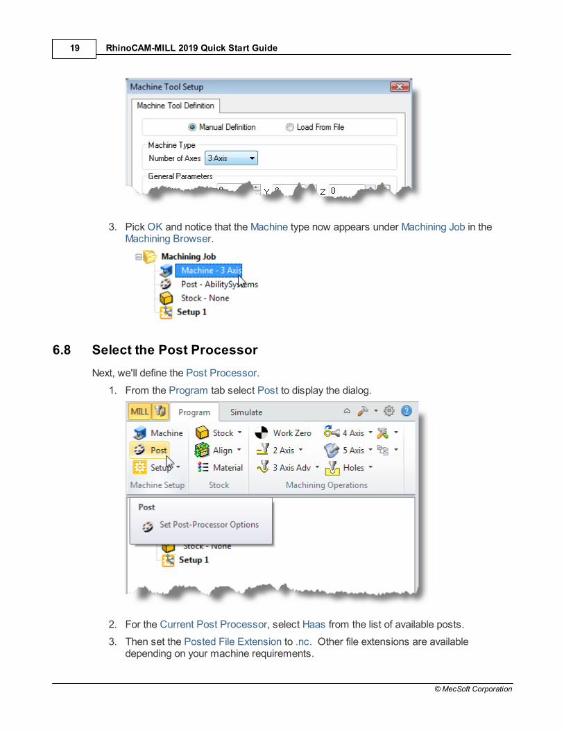
1. From the Program tab select Machine to display the dialog box.
2. Under Machine Type, set the Number of Axes to 3 Axis.
RhinoCAM-MILL 2019 Quick Start Guide19
© MecSoft Corporation
3. Pick OK and notice that the Machine type now appears under Machining Job in theMachining Browser.
6.8 Select the Post Processor
Next, we'll define the Post Processor.
1. From the Program tab select Post to display the dialog.
2. For the Current Post Processor, select Haas from the list of available posts.
3. Then set the Posted File Extension to .nc. Other file extensions are availabledepending on your machine requirements.

Getting Ready 20
© MecSoft Corporation
By default, post processor files are located under
C:\ProgramData\MecSoft Corporation\RhinoCAM 2019 for Rhinox.x\Posts\MILL\
The program to send the posted output data to is set to notepad.
4. Pick OK and notice that the Post type now appears under Machining Job in theMachining Browser.

RhinoCAM-MILL 2019 Quick Start Guide21
© MecSoft Corporation

The Setup 22
© MecSoft Corporation
The Setup
7.1 Machining Setup - Skip if in STD or EXP Configuration
Now let's define the Machining Setup. The Machining Setup allows you to orient the MachineCoordinate System such that the part is aligned in exactly same way as it would be fixturedon the machine tool for cutting.
This functionality is available only in the Professional andPremium configurations of the product. When working with
your part files and running the Express, Standard or Expertconfiguration, you will have to use the CAD tools to orient the partgeometry so that it is in the correct orientation for machining.
If in the future, if there is no Setup1 listed under your Machining Job, the system automaticallycreates one when a Work Zero or an operation is generated.
However in our tutorial part, by default, the MCS (Machine Coordinate System) is alreadyaligned with the WCS (World Coordinate System) so this step is not required for this part.
However, in production you can have multiple setups and assign different machiningorientations for each, when running the Professional or Premium configurations.
7.2 Create Stock Geometry
In this step we'll define the raw stock from which to cut the part.
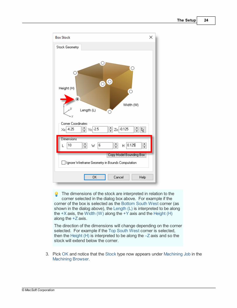
1. From the Program tab select Stock and then select Box Stock from the menu todisplay the dialog.

RhinoCAM-MILL 2019 Quick Start Guide23
© MecSoft Corporation
2. Under Dimensions, set the Length L to 10.0, Width W to 6.0 and Height H to 0.125.Note that the stock dimensions you enter are measured from the corner of thebounding box selected in this dialog.
The Setup 24
© MecSoft Corporation
The dimensions of the stock are interpreted in relation to thecorner selected in the dialog box above. For example if the
corner of the box is selected as the Bottom South West corner (asshown in the dialog above), the Length (L) is interpreted to be alongthe +X axis, the Width (W) along the +Y axis and the Height (H)along the +Z axis.
The direction of the dimensions will change depending on the cornerselected. For example if the Top South West corner is selected,then the Height (H) is interpreted to be along the –Z axis and so thestock will extend below the corner.
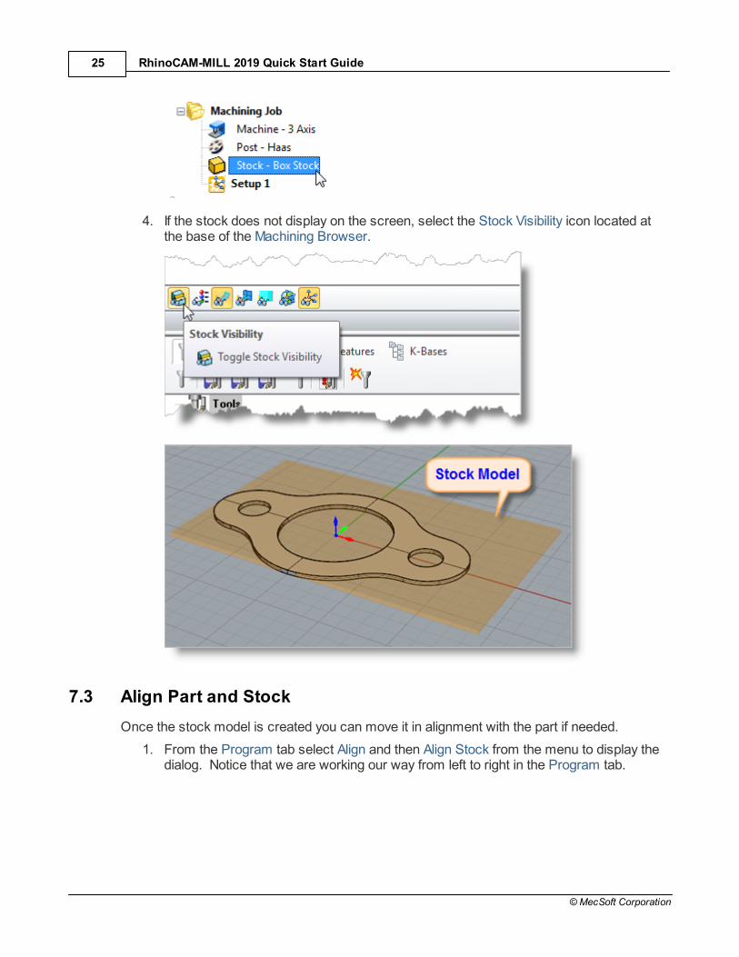
3. Pick OK and notice that the Stock type now appears under Machining Job in theMachining Browser.
RhinoCAM-MILL 2019 Quick Start Guide25
© MecSoft Corporation
4. If the stock does not display on the screen, select the Stock Visibility icon located atthe base of the Machining Browser.
7.3 Align Part and Stock
Once the stock model is created you can move it in alignment with the part if needed.
1. From the Program tab select Align and then Align Stock from the menu to display thedialog. Notice that we are working our way from left to right in the Program tab.

The Setup 26
© MecSoft Corporation
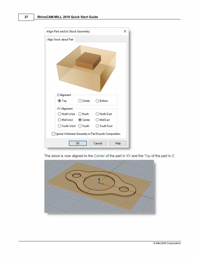
2. For Z Alignment select Top and for XY Alignment select Center and then pick OK.
RhinoCAM-MILL 2019 Quick Start Guide27
© MecSoft Corporation
The stock is now aligned to the Center of the part in XY and the Top of the part in Z.
The Setup 28
© MecSoft Corporation
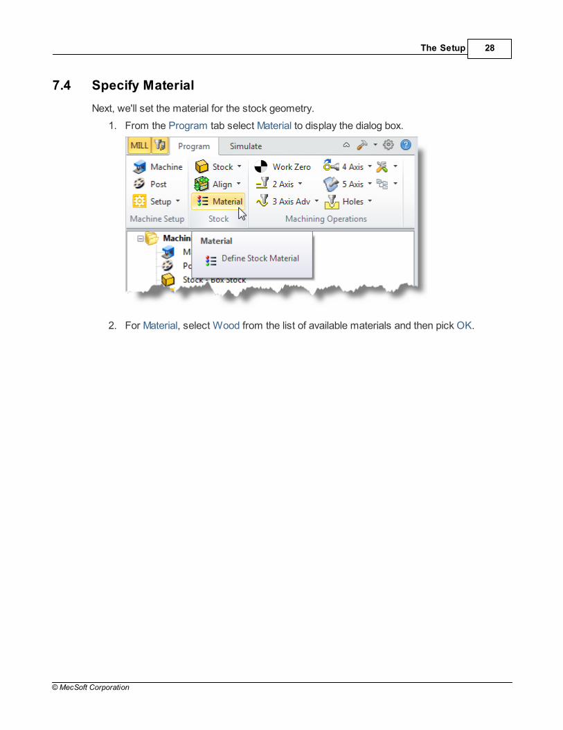
7.4 Specify Material
Next, we'll set the material for the stock geometry.
1. From the Program tab select Material to display the dialog box.
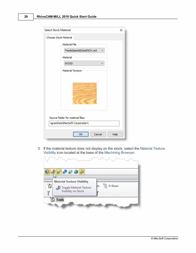
2. For Material, select Wood from the list of available materials and then pick OK.
RhinoCAM-MILL 2019 Quick Start Guide29
© MecSoft Corporation
3. If the material texture does not display on the stock, select the Material TextureVisibility icon located at the base of the Machining Browser.
The Setup 30
© MecSoft Corporation
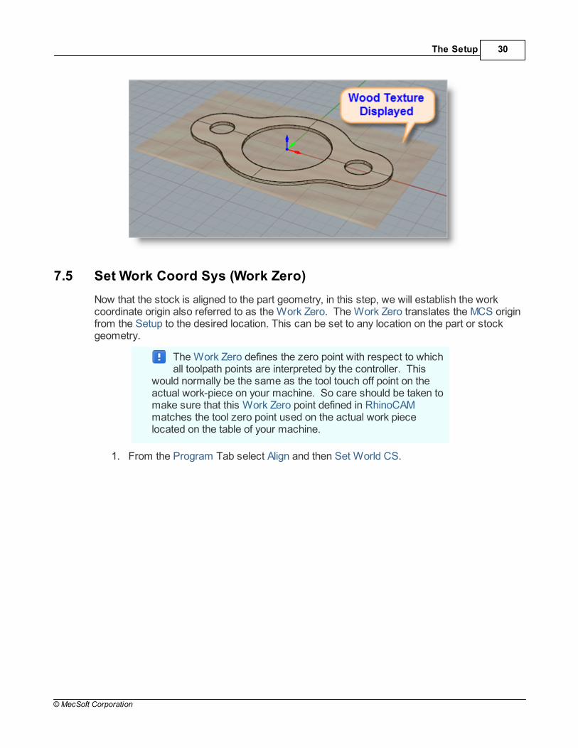
7.5 Set Work Coord Sys (Work Zero)
Now that the stock is aligned to the part geometry, in this step, we will establish the workcoordinate origin also referred to as the Work Zero. The Work Zero translates the MCS originfrom the Setup to the desired location. This can be set to any location on the part or stockgeometry.
The Work Zero defines the zero point with respect to whichall toolpath points are interpreted by the controller. This
would normally be the same as the tool touch off point on theactual work-piece on your machine. So care should be taken tomake sure that this Work Zero point defined in RhinoCAMmatches the tool zero point used on the actual work piecelocated on the table of your machine.
1. From the Program Tab select Align and then Set World CS.

RhinoCAM-MILL 2019 Quick Start Guide31
© MecSoft Corporation
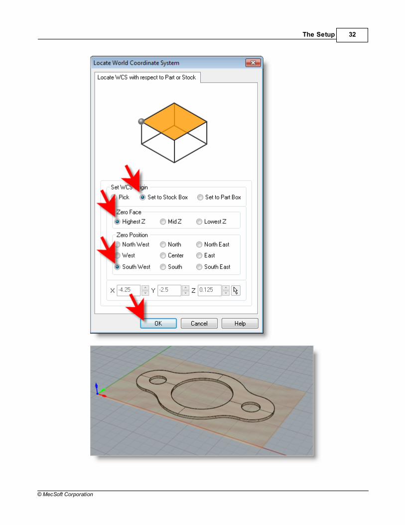
2. Then select Set to Stock Box.
3. Then set Zero Face to Highest Z and Zero Position to South West corner. This setsthe machine home to the top of the stock material and the southwest corner of thestock geometry.
4. Pick OK and the part and stock geometry are now transformed to the WorldCoordinate Origin (WCS).
The Setup 32
© MecSoft Corporation

RhinoCAM-MILL 2019 Quick Start Guide33
© MecSoft Corporation
Alternatively you can use Work Zero to set the work coordinate origin. Instead of moving thepart and stock to the WCS origin, this moves the machine coordinate system origin to thespecified location.
1. From the Program Tab select Work Zero to display the dialog.
5. Then select Set to Stock Box.
6. Then set Zero Face to Highest Z and Zero Position to South West corner. This setsthe machine home to the top of the stock material and the southwest corner of thestock geometry.

The Setup 34
© MecSoft Corporation
7. Pick Generate and notice that the MCS is translated and that the Work Zero nowappears under Setup 1 in the Machining Browser.

RhinoCAM-MILL 2019 Quick Start Guide35
© MecSoft Corporation
Note that the Work Zero should appear as the FIRST itemUNDER the Setup in the Machining Job tree so that all
operations in that Setup will inherit that Work Zero origin.

Create Tools 36
© MecSoft Corporation
Create Tools
To machine the above part we will now create a ½ inch (0.5”) Flat End Mill.
1.
2. This will display the Create/Select Tool dialog. Select Flat Mill from the Tool Typemenu at the top of the dialog.
3. Set tool Name to FlatMill-0.5 and Tool Diameter to 0.5. Under the Properties tab setMaterial to HSS and Tool Number to 1.

RhinoCAM-MILL 2019 Quick Start Guide37
© MecSoft Corporation
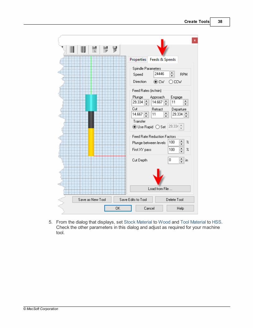
4. Switch to Feeds and Speeds tab and click Load from File.
Create Tools 38
© MecSoft Corporation
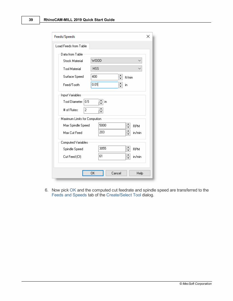
5. From the dialog that displays, set Stock Material to Wood and Tool Material to HSS. Check the other parameters in this dialog and adjust as required for your machinetool.
RhinoCAM-MILL 2019 Quick Start Guide39
© MecSoft Corporation
6. Now pick OK and the computed cut feedrate and spindle speed are transferred to theFeeds and Speeds tab of the Create/Select Tool dialog.

Create Tools 40
© MecSoft Corporation
7. Pick Save as New Tool to save the tool. The tool is now created and listed underTools in Session on the left side of the dialog.
8. Pick OK to close the dialog.
You can edit the tool properties and pick Save Edits to Tool tosave the changes to this tool. To edit and save this as a New
Tool, you must enter a different tool Name.
The created tool is now listed under the Tools tab in Machining Objects browser.
In the future you can save your tools to a Tool Library. Tosave Tools to a library, click Save Tool Library under the

RhinoCAM-MILL 2019 Quick Start Guide41
© MecSoft Corporation
Tools tab in the Machining Objects Browser and specify a folderlocation and file name in the Save as dialog box. Two Tool Libraryfile formats are supported (*.vkb and *.csv). The native ToolLibrary file format for RhinoCAM is *.vkb.
Machine the Inner Profiles 42
© MecSoft Corporation
Machine the Inner Profiles
Now we're ready to create our first machining operation.
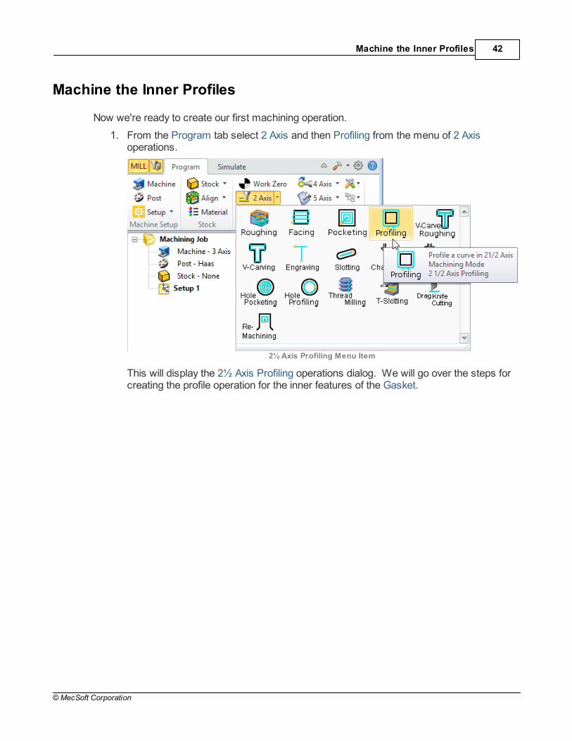
1. From the Program tab select 2 Axis and then Profiling from the menu of 2 Axisoperations.
2½ Axis Profiling Menu Item
This will display the 2½ Axis Profiling operations dialog. We will go over the steps forcreating the profile operation for the inner features of the Gasket.

RhinoCAM-MILL 2019 Quick Start Guide43
© MecSoft Corporation
9.1 Control Geometry
2. Under the Control Geometry tab pick Select Curve/Edge Regions.
The Profiling operation dialog is now minimized and allows selection of features tomachine. We will now select the surface edges of the 3 inside hole features.
3. Select the first hole by clicking near the upper surface edge as shown below.

Machine the Inner Profiles 44
© MecSoft Corporation
4. Repeat to select the edges of the two smaller holes.
Press <Enter> or right-click to end the selection.
5. The 2½ Axis Profiling dialog comes back up displaying the selected Part Regions. They are also highlighted on the part.
6. Notice that selecting a Part Region from the list highlights the corresponding surfaceedge curve on the part.

RhinoCAM-MILL 2019 Quick Start Guide45
© MecSoft Corporation
9.2 Cutting Tool
Now we'll select the Tool for our operation:
1. Switch to the Tool tab of the dialog.
2. Select Flat Mill-0.5 under Tools. The 0.5" Flat End Mill is now selected as the activetool.

Machine the Inner Profiles 46
© MecSoft Corporation
Note that the Tool parameters of the currently active tool are always displayed in thestatus bar at the bottom of the Machining Objects Browser.
9.3 Feeds and Speeds
Now we'll set the Speeds and Feeds for our operation:
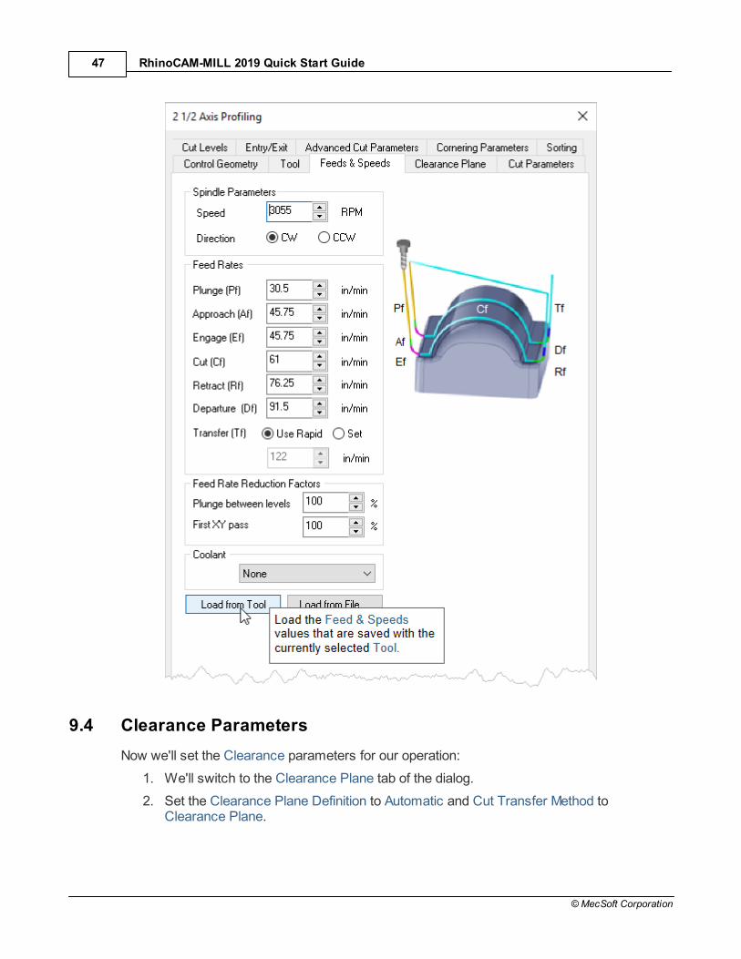
1. Switch to the Feeds & Speeds tab of the dialog.
2. Select the Load from Tool button. RhinoCAM will retrieve the feeds and speedsparameters that were set when the tool was defined and associate them with thecurrent operation.
RhinoCAM-MILL 2019 Quick Start Guide47
© MecSoft Corporation
9.4 Clearance Parameters
Now we'll set the Clearance parameters for our operation:
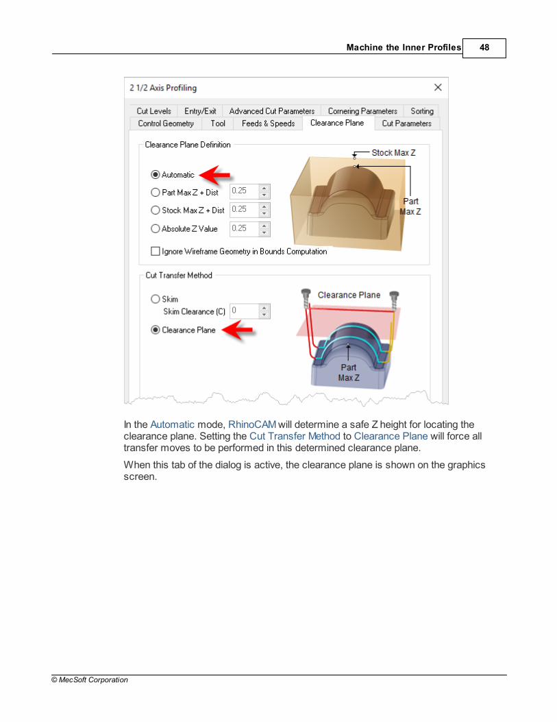
1. We'll switch to the Clearance Plane tab of the dialog.
2. Set the Clearance Plane Definition to Automatic and Cut Transfer Method toClearance Plane.
Machine the Inner Profiles 48
© MecSoft Corporation
In the Automatic mode, RhinoCAM will determine a safe Z height for locating theclearance plane. Setting the Cut Transfer Method to Clearance Plane will force alltransfer moves to be performed in this determined clearance plane.
When this tab of the dialog is active, the clearance plane is shown on the graphicsscreen.

RhinoCAM-MILL 2019 Quick Start Guide49
© MecSoft Corporation
9.5 Cut Parameters
Now we'll set the Cut Parameters for our operation:
1. Switch to the Cut Parameters tab of the dialog.
2. Set the Stock to 0. This means that we will not be leaving any thickness on the partafter machining.
3. Under Cut Start Point, uncheck Use Mid-Point of longest side.
4. Under the Cut Start Side section check the box next to Use Outside/Inside for ClosedCurves and then select Inside.

Machine the Inner Profiles 50
© MecSoft Corporation
Alternately you could use the Determine using 3D Model option. In this caseRhinoCAM would use the 3D model to determine which side of the curve to place thecutter for machining.
9.6 Cut Level Parameters
Now we'll set the Cut Level parameters for our operation:
1. Select the Cut Levels tab of the dialog.
2. Set Location of Cut Geometry to At Top.

RhinoCAM-MILL 2019 Quick Start Guide51
© MecSoft Corporation
3. For Total Cut Depth, enter 0.125. The cut depth is always set as an absolute value.
4. This automatically sets the Rough Depth and Rough Depth/Cut to 0.125.
9.7 Entry/Exit Parameters
Next we'll set Entry and Exit parameters for our operation:
1. Select the Entry/Exit tab of the dialog.
2. Entry/Exit parameters control how the cutter will engage material as it begins cuttingand how it leaves the material as it completes cutting.
3. Set Entry Motions and Exit Motions to None.
4. Now pick Generate.

Machine the Inner Profiles 52
© MecSoft Corporation
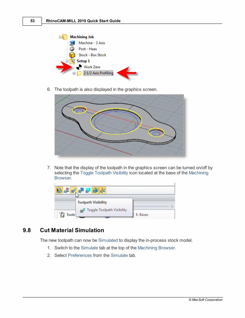
5. The 2½ Axis Profile toolpath is generated and the operation is listed under Setup 1 inthe Machining Browser. NOTE: Notice that it appears UNDER the Work Zero in theSetup.
RhinoCAM-MILL 2019 Quick Start Guide53
© MecSoft Corporation
6. The toolpath is also displayed in the graphics screen.
7. Note that the display of the toolpath in the graphics screen can be turned on/off byselecting the Toggle Toolpath Visibility icon located at the base of the MachiningBrowser.
9.8 Cut Material Simulation
The new toolpath can now be Simulated to display the in-process stock model.
1. Switch to the Simulate tab at the top of the Machining Browser.
2. Select Preferences from the Simulate tab.

Machine the Inner Profiles 54
© MecSoft Corporation
3. From the Preferences dialog set the following:
Simulation Model: Polygonal ModelSimulation Accuracy: FineRemove Remnants During Simulation: UncheckedDisplay Tool Holder During Simulation: Checked

RhinoCAM-MILL 2019 Quick Start Guide55
© MecSoft Corporation
Set Simulation Preferences

Machine the Inner Profiles 56
© MecSoft Corporation
4. Now pick OK to close the Simulation Preferences dialog.
5. Pick OK from the message dialog.
6. Then from the Simulate tab, uncheck Simulate by Moves and adjust the slider to theleft to slow down the simulation speed.
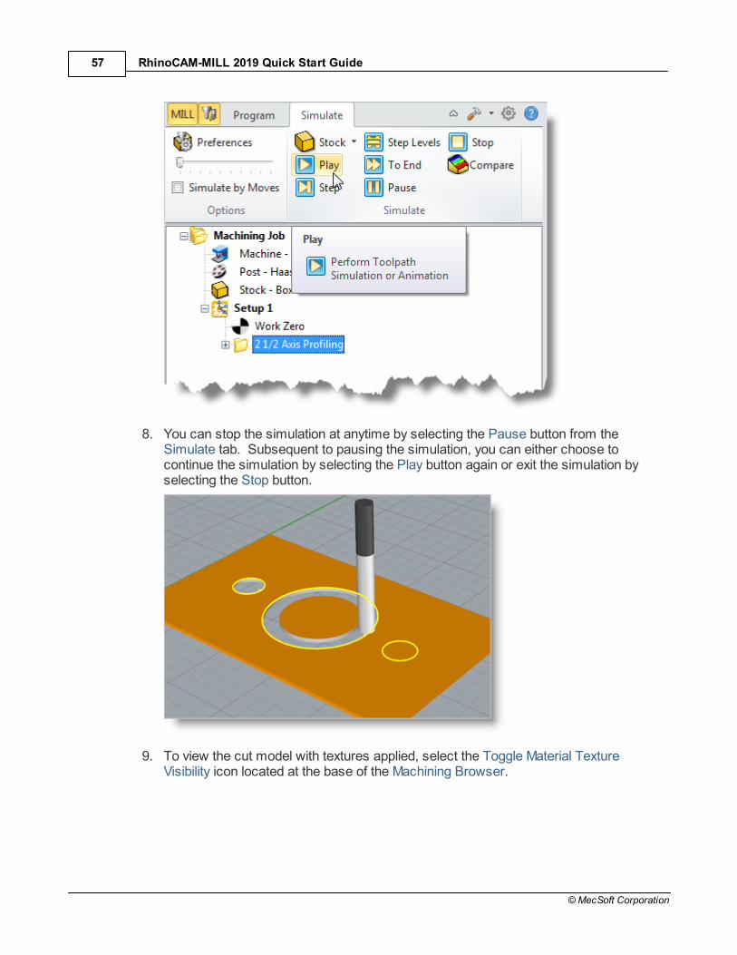
7. Now, under Setup 1 in the Machining Job tree, select the 2½ Axis Profiling operationwe just created and then pick Play to start the simulation.
RhinoCAM-MILL 2019 Quick Start Guide57
© MecSoft Corporation
8. You can stop the simulation at anytime by selecting the Pause button from theSimulate tab. Subsequent to pausing the simulation, you can either choose tocontinue the simulation by selecting the Play button again or exit the simulation byselecting the Stop button.
9. To view the cut model with textures applied, select the Toggle Material TextureVisibility icon located at the base of the Machining Browser.

Machine the Inner Profiles 58
© MecSoft Corporation

RhinoCAM-MILL 2019 Quick Start Guide59
© MecSoft Corporation
Machine the Outer Profile
Now we will turn our attention to machining the outer profile of the part. Again, we will create asimple profile toolpath, this time around the outer perimeter of the part.
1. Switch to Program tab in the Machining Browser.
2. Select the 2½ Axis Profiling operation we just created.
3. Right-click on the selected operation and select Copy.
4. Now Right-click again and select Paste.

Machine the Outer Profile 60
© MecSoft Corporation
5. This creates a copy of the operation and places it below the original in the MachiningJob.

RhinoCAM-MILL 2019 Quick Start Guide61
© MecSoft Corporation
6. Now right-click on the second operation and pick Edit to adjust its parameters.
7. From the Control Geometry tab, pick Remove All.
8. From the Control Geometry tab, pick Select Curve/Edge Regions.
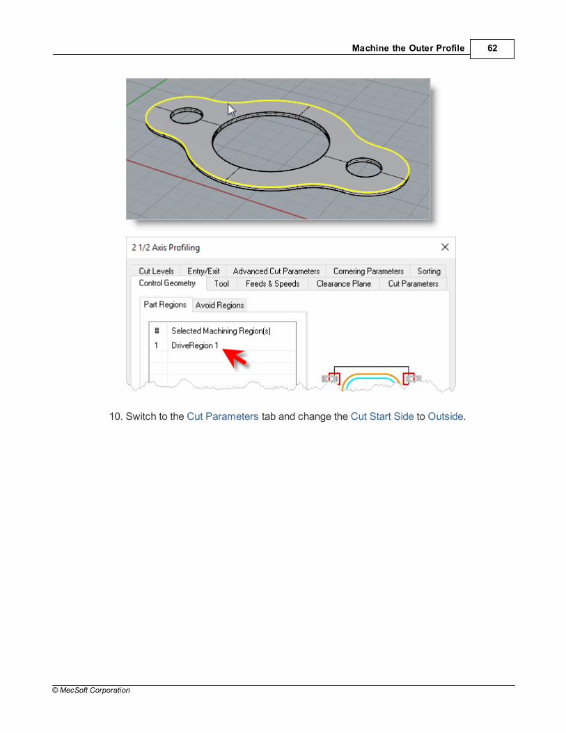
9. Select the top outer surface edge and then right-click or press enter to complete theselection.
Machine the Outer Profile 62
© MecSoft Corporation
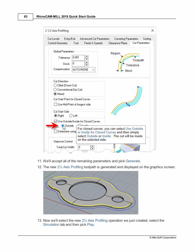
10. Switch to the Cut Parameters tab and change the Cut Start Side to Outside.
RhinoCAM-MILL 2019 Quick Start Guide63
© MecSoft Corporation
11. We'll accept all of the remaining parameters and pick Generate.
12. The new 2½ Axis Profiling toolpath is generated and displayed on the graphics screen.
13. Now we'll select the new 2½ Axis Profiling operation we just created, select theSimulation tab and then pick Play.

Machine the Outer Profile 64
© MecSoft Corporation

RhinoCAM-MILL 2019 Quick Start Guide65
© MecSoft Corporation
Post G-Code
Now with the toolpaths complete we're ready to post-process to an output text file containingG-codes that can then be sent to the machine tool to actually machine the part.
1. Select Setup 1 from the Machining Job, right-click and select Post. This will post-process all operations created under the Setup.
2. The Post & Save As dialog is displayed. By default, the Part file name and the Setupname are appended for the G-code File name. Also by default, the posted G-code fileis Saved in the folder where the part file is located.
The output file names can be controlled by setting the PostedFile Naming Conventions sections of the Set Post-Processor
Options dialog. Refer to the Select the Post Processor step fordisplaying this dialog.

Post G-Code 66
© MecSoft Corporation
As you may recall we set the post to Haas back in the SelectPost Processor section of this guide. You can change the
post processor from this dialog by selecting a different one fromthe drop down menu in the Current Post list. The posted G-codeby default will be saved to the folder where the part file is located.
3. Now pick Post and the G-code file is displayed in Notepad where it can be viewed oredited manually.

RhinoCAM-MILL 2019 Quick Start Guide67
© MecSoft Corporation
4. Now close Notepad.

Generate Reports 68
© MecSoft Corporation
Generate Reports
12.1 Information Report
At any time, you can create a Report of your Machining Operations.
1. Switch to Program tab in the Machining Browser.
2. Select Setup 1.
3. Right-click and select Information to display and Print the report.
This dialog provides an estimate of the machining time required for the operations inthe Setup.
Note (Professional & Premium configurations only): In the future, if your MachiningJob contains multiple Setups, you can perform the same right-click sequence on theMachining Job to determine the estimated machining time for all Setups.

RhinoCAM-MILL 2019 Quick Start Guide69
© MecSoft Corporation
4. Now pick OK to close the Information dialog.
12.2 Shop Documentation
You can also create a Setup Sheet by generating a Shop Document. This is typically used toinstruct machine operators on how to setup and machine the part on the CNC machine.
1. Under the Machining Job, select Setup1.
2. Right-click and select Shop Documentation.
3. From the Save Shop Documentation File dialog, select Template1 and pick Save.

Generate Reports 70
© MecSoft Corporation
4. This creates an HTML based Shop Document that can be viewed in a web browser.
You can select from one of the multiple HTML templates that are shipped with theproduct and generate shop documentation. Each template provides varying amountsof information. Once you have selected the Output Template and pick Save, a shopdocumentation html file will be created and saved. This file can then be printed and/orviewed in your default web browser such as Internet Explorer.

RhinoCAM-MILL 2019 Quick Start Guide71
© MecSoft Corporation
5. Note (Professional & Premium configurations only): In the future, if your MachiningJob contains multiple Setups, you can perform the same right-click sequence on theMachining Job to generate Shop Documentation for all Setups.

Where to go for more help 72
© MecSoft Corporation
Where to go for more help
If you need additional help please take advantage of the following MecSoft resources:
1. Quick Start Guides RhinoCAM includes step-by-step Quick Start Guides to help you get started using theprogram. You can find these and other resources on the Learning Resources dialog.
2. On-Line Help The on-line help distributed with the product is a great resource to find referenceinformation on the various functions available. You will find links to the online help foreach module and other resources on the Learning Resources dialog (RhinoCAM >Learning...).
3. Best Practices in 3 Axis MachiningThis is an extended 5,000+ word original content article on The MecSoft Blog packedfull of Best Practices advice prepared by the MecSoft support staff! 3 Axis machiningis THE MOST common application for all of MecSoft’s CAM milling plugins. Thereason is quite simple. This suite of toolpath strategies can quickly and accuratelymachine a vast majority of components and tooling required by industry today. In thispost we’ll explore some of the Best Practices for machining in 3 Axis using MecSoftCAM. Read the full article...
4. Best Practices in 2-1/2 Axis Machining2½ Axis machining is the 2nd most common application (behind 3 Axis machining) forall of MecSoft’s CAM plugins. The reason for this is because a large number of partsfound in the real world lend themselves to 2½ Axis machining. The majority of 2½ Axiscomponents are simple prismatic shapes composed of drilled holes, flat horizontalfaces and straight or drafted verticals walls. Read the full article...
5. MecSoft.com Resources Page You can find learning materials and industry resources on the MecSoft.comResources Page.
6. Free Videos You can visit the MecSoft Corporation YouTube Channel to watch videos. Note thatthe functionality of MecSoft's CAM products is very similar across each of the differentplatforms that we support!
7. MecSoft Blog You can visit the MecSoft Blog for short articles about using our products.
8. Case Studies You can also visit our real-world Case Studies page to learn how others are usingMecSoft products in their workshops.
9. CAMJam Video Archive If you are an active AMS (Annual Maintenance Subscription) user, you have freeaccess to our CAMJam self-training video archive and companion guide containingover 80 videos from our support staff on every aspect of RhinoCAM. If you are new orhave recently signed up for AMS, this document will show you how to access yourCAMJam archive. Want to sign up for AMS? Just give a call at 949-654-8163 (selectOption 1 for Sales).
RhinoCAM-MILL 2019 Quick Start Guide73
© MecSoft Corporation
10. Support Forums If you are an active AMS (Annual Maintenance Subscription) user, you have freeaccess to our Premium Support Forums where you can discuss projects with otherexperienced users that eager to assist. If you are new or have recently signed up forAMS, this document will show you how to access the Premium Support Forums. Want to sign up for AMS? Just give a call at 949-654-8163 (select Option 1 for Sales).
11. Knowledge Resources Forum If you are an active AMS (Annual Maintenance Subscription) user, you have freeaccess to the Knowledge Resources Forum (part of the Premium Support Forums)where you will find additional tutorial documents and source files such as The F1 CO2Racer Body Tutorial and The Cutting Tools Workbook. If you are new or have recentlysigned up for AMS, this document will show you how to access the Premium SupportForums. Want to sign up for AMS? Just give a call at 949-654-8163 (select Option 1for Sales).
12. MecSoft Support If you need additional help, or if you have any questions regarding RhinoCAM, you maycontact us via e-mail at [email protected] or our online support page.
13. On-Demand Training MecSoft Corporation offers On-Demand Training as well as personalized full daytraining sessions. Please look up our website or email us at [email protected] forfurther details
14. Product Page Please do continue to visit the RhinoCAM product page to learn about the latestupdates and additional help material.

Index 74
© MecSoft Corporation
Index- 2 -2½ Axis Profiling 42
Clearance Plane tab 47
Control Geometry tab 43
Copy/Paste 59
Cut Levels tab 50
Cut Parameters 49
Edit 59
Entry/Exit tab 51
Feeds and Speeds tab 46
Information Report 68
Post G-Code 65
Simulate 53
Tool tab 45
- A -About
the MILL Module 9
the RhinoCAM Display 11
This Guide 9
using this Guide 9
Align Part and Stock 25
- C -Clearance Plane 47
Control Geometry 43
Copy/Paste a Toolpath 59
Create Machining Operations 42
Create Stock Geometry 22
Create Tools 36
Cut Levels
2½ Axis Profiling 50
Cut Parameters
2½ Axis Profiling 49
- D -Define the Machine Tool 18
- E -Entry/Exit
2½ Axis Profiling 51
- G -Generating Reports 68
Getting Ready
Load the Part Model 15
Machining Strategy 17
Main Programming Steps 18
- L -Learning Resources 6
Load the Part Model 15
Load the RhinoCAM MILL Module 12
- M -Machine
Define 18
Machining Setup - Skip if in STD or EXP Configuration 22
Machining Strategy 17
Machining the Outer Perimeter 59
Machining Time 68
Main Programming Steps 18
- P -Post
Create G-Code 65
Select 19
Profiling 42
- Q -Quick Start Guides 6
- R -Running RhinoCAM 11
RhinoCAM-MILL 2019 Quick Start Guide75
© MecSoft Corporation
- S -Select Cutting Tool 45
Select the Post Processor to use 19
Set Feeds and Speeds 46
Set Work Zero 30
Setup
Machine 22
Setup Sheet 69
Shop Documentation 69
Simulate
2½ Axis Profiling 53
Specify Material 28
Stock
Align with Part 25
Create Box Stock 22
Specify Material 28
- T -Tool
Create 36
- U -Useful Tips 4
Using this Guide and Associated Part Files 9
- V -Videos & Guides 6
- W -What's New 5
Where to go for more help 72
Work Zero 30