rhic electron lenses - brookhaven national laboratory · 2009-07-21 · bunch intensity 109 1.1 1.0...
TRANSCRIPT
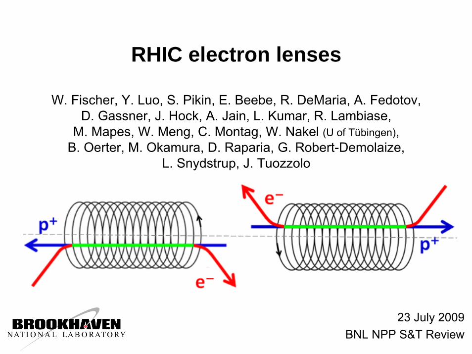
RHIC electron lenses
W. Fischer, Y. Luo, S. Pikin, E. Beebe, R. DeMaria, A. Fedotov, D. Gassner, J. Hock, A. Jain, L. Kumar, R. Lambiase,
M. Mapes, W. Meng, C. Montag, W. Nakel (U of Tübingen), B. Oerter, M. Okamura, D. Raparia, G. Robert-Demolaize,
L. Snydstrup, J. Tuozzolo
23 July 2009BNL NPP S&T Review
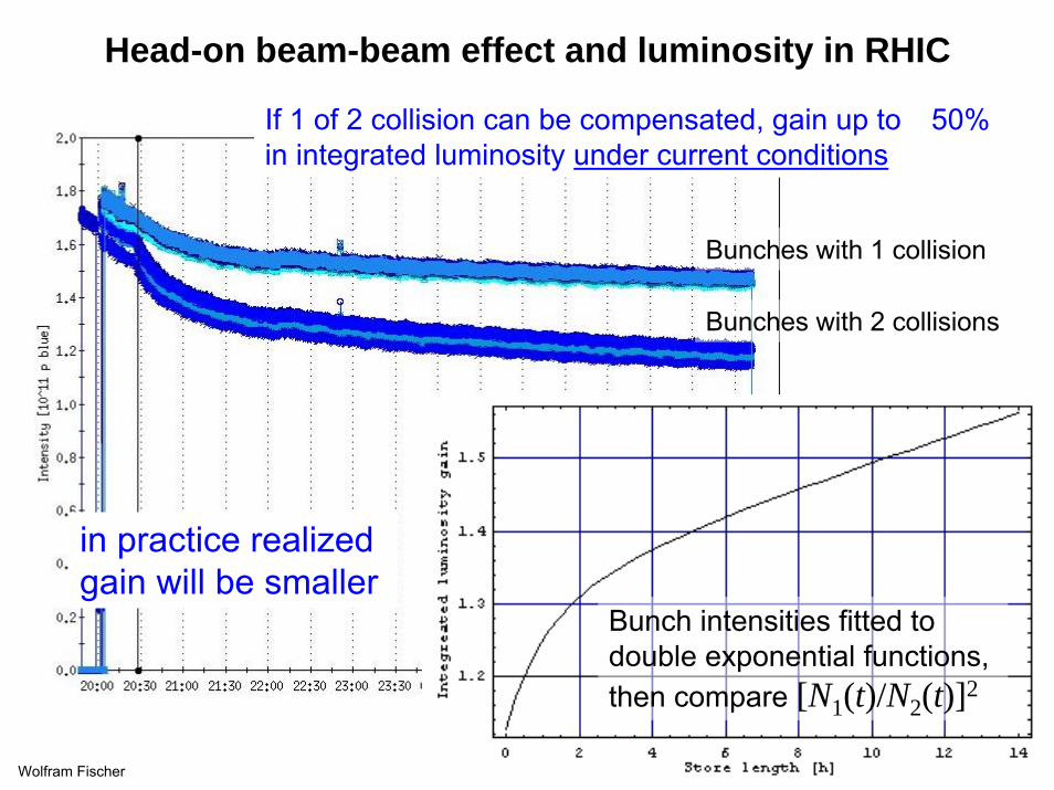
Head-on beam-beam effect and luminosity in RHIC
Wolfram Fischer 2
If 1 of 2 collision can be compensated, gain up to �50% in integrated luminosity under current conditions
Bunches with 1 collision
Bunches with 2 collisions
Bunch intensities fitted to double exponential functions, then compare [N1(t)/N2(t)]2
in practice realized gain will be smaller

Head-on beam-beam effect and luminosity in RHIC
More luminosity can be gained with an increase in the bunch intensity:
Increase of bunch intensity requires:
1. Upgrade of the polarized proton sourceapproximately 3-year effort, started (A. Zelenski)
2. Upgrades in RHICimprovements to deal with larger stored energy, collimation, dump, andinstrumentationstarted process to enlarge Accelerator Safety Envelope for 2x intensity
Wolfram Fischer 3
*
2
4 βεπbcNfL =
If 1 of 2 collisions can be compensated,then Nb can be doubled while totalbeam-beam ξ ∼ Nb/ε is maintained
This would yield theoretically a factor 4,expect in practice about a factor 2.

Wolfram Fischer 4
Luminosity and polarization goals
Parameter unit Achieved Enhanced design
Next Lupgrade
Au-Au operation (2007) (� 2012)
Energy GeV/nucleon 100 100 100No of bunches … 103 111 111Bunch intensity 109 1.1 1.0 1.0Average L 1026cm-2s-1 12 8 40p↑- p↑ operation (2009) (� 2011/12) (� 2014)
Energy GeV 100 / 250 100 / 250 250No of bunches … 109 109 109Bunch intensity 1011 1.3 / 1.1 1.3 / 1.5 2.0Average L 1030cm-2s-1 24 / 55 30 / 150 300Polarization P % 55 / 34 70 70

Beam-beam compensation concept with electron lens
Exact compensation if x3(N1,N2) = x3(0,0) and x’3(N1,N2) = x’
3(0,0) :
1. Same amplitude dependent force in p-beam and e-beam lens, and2. Phase advance between p-beam and e-beam lens is ΔΨ = kπ, and3. No nonlinearities between p-beam and e-beam lens
Wolfram Fischer 5
p-beam lens defocuses e-beam lens focuses
p-beam
Condition 1 cannot be realized with magnets, requires an electron beam
beam-beam kick
magnet kicks

History of head-on beam-beam compensation (HOBBC)
• Compensation schemes (S. Peggs, Handbook):1. Direct space charge compensation (4 beams)2. Indirect space charge compensation (electron lenses)3. Betatron phase cancellation between neighboring IPs
• Proposals/studies of head-on beam-beam compensation to date:• COPPELIA 4-beam (J.E. Augustine, HEACC, 1969)
• DCI 4-beam (G. Arzelia et al., HEACC, 1971) � only real attempt so far• CESR e-lens (R. Talman, unpublished, 1976)
• SSC e-lens (E. Tsyganov et al., SSCL-PREPRINT-519 ,1993)
• LHC e-lens (E. Tsyganov et al., CERN SL-Note-95-116-AP, 1995)
• Tevatron e-lens (Shiltsev et al., PRST-AB, 1999)
• e+e collider 4-beam (Y. Ohnishi and K. Ohmi, Beam-Beam’03, 2003)
considered for RHIC
Wolfram Fischer 6
failed because of coherent instabilities

Electron lenses in RHIC
Wolfram Fischer 7
[Y. Luo and W. Fischer, “Outline of using an electron lens for the RHIC …”, BNL C-AD/AP/284 (2007)]
IP8 �IP10 Δψy = 10.9 π
IP6�IP10Δψx = 19.1 π
• Both lenses near IP10,between DX magnets (βx= βy)
• Blue and Yellow beams ver.separated like in other IPs
• Solenoids of different polarity(minimizes effect on linear coupling and spin)
• default Δφx � kπ, IP6 � IP10 default Δφy � kπ, IP8 � IP10(C. Montag working on lattice optimization)

Electron lens simulations – Y. Luo et al.
Wolfram Fischer 8
[Y. Luo, W. Fischer, and N. Abreu, “Stability of single particle motion with head-on beam-beamcompensation in the RHIC”, BNL C-AD/AP/310 (2008).]
E-lens compresses tune footprints
Tune footprint compression is not sufficient for better beam lifetime.Full compensation folds footprint – known to be problematic.
� Use only partial compensation.

Electron lens simulations – Y. Luo et al.
Wolfram Fischer 9
[Y. Luo, W. Fischer, and N. Abreu, “Stability of single particle motion with head-on beam-beamcompensation in the RHIC”, BNL C-AD/AP/310 (2008).]
E-lens reduces tune diffusion in core (<3σ), increases in tail (>4σ)
No BB BB
Half BBC Full BBC
Tune change over 2 successive periods
of 1024 turns
22 |||||| yx QQQ Δ+Δ=Δ

Beam lifetime simulations – Y. Luo et al.
Wolfram Fischer 10
No BBC Nb=3.0�1011
No BBC Nb=2.5�1011
Half BBC Nb=2.5�1011
Half BBC Nb=3.0�1011
Weak-strong beam-beam simulations with detailed lattice (SixTrack)
[Conditions: nonlinear IR errors and arc sextupoles included, 4D BB at IP6 and IP8, zero length e-lens at IP10, core tunes at (0.67,0.67) and chromaticities of +1 for all cases, 250 GeV, 6.5k particles in Gaussian distribution]

Electron lenses in RHIC
Wolfram Fischer 11
� Tevatron e-lens
BNL EBIS �

Head-on beam-beam compensation with electron lenses
• Design considerations driven by p-beam• RHIC beam size: σ = 0.25 mm rms (βxy � 10-20 m)
• Solenoid strength and field quality• Magnetic compression of electron beam to p-beam � 6 T• Solenoid field lines straight within ~0.2 σ (�50 μm)
• Electron gun parameters• Small RHIC beam sizes with possible magnetic compression
from 0.2 T on gun to 6 T in electron lens requires current densities of 14 A/cm2, need IrCe cathodes for good lifetime (A. Pikin)
• Alignment of proton and electron beam � found to be of critical importance in Tevatron• Straightness of solenoid field (�50 μm)• Instrumentation
(BPMs, BTF, “luminosity” monitors – probably bremsstrahlung)
Wolfram Fischer 12

Electron lens main solenoids
Wolfram Fischer 13
Main solenoids:• 2.5 m long
(2 m good field region)• 6 T (superconducting) • ID 250 mm• Warm insert with
• field correction(up to 10 correctors/plane)
• orbit correction• angle correction
• Field line straightness �50 μm Draft by S. Pikin

Mechanical force calculations – W. Meng, S. Pikin
Wolfram Fischer 14

Instrumentation – D. Gassner
Wolfram Fischer 15
For accurate relative beamalignment would like to have “luminosity” monitor based on• bremsstrahlung, or• back-scattered electrons(C. Montag, W. Nakel)
Relative beam alignment was of critical importance in Tevatron.
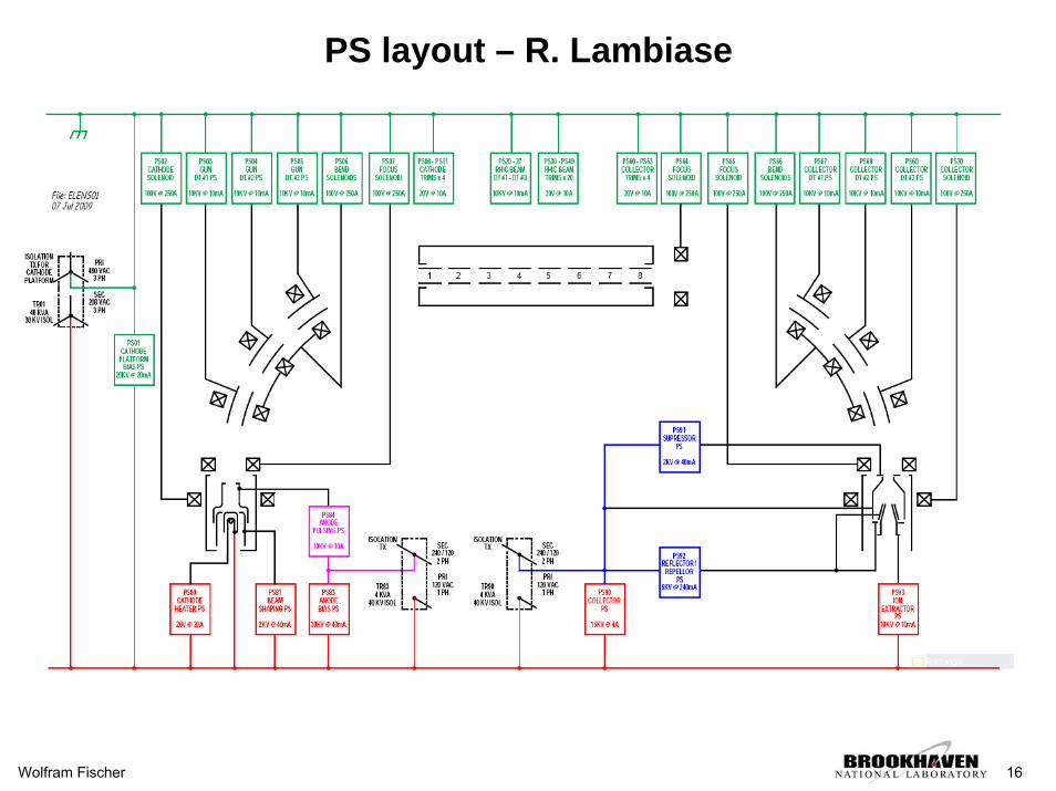
PS layout – R. Lambiase
Wolfram Fischer 16

RHIC electron lenses – funding and schedule
25 Jun 2009 Received $4M (including $1M for labor) through ARRA (American Recovery and Reinvestment Act of 2009)
Aug 2009 Solenoids including power supply ready to orderJan 2010 Gun and collector ready to orderFeb 2010 Beam transport system ready to orderMay 2010 Diagnostics ready to orderNov 2010 Solenoid acceptance testMar 2011 Control system specifiedJun 2011 Begin tunnel installationDec 2011 Tunnel installation complete
So far: hired 1 electrical engineer, 1 post-doc position open.
Collaboration with US LHC Accelerator Research Program (LARP) and CERN on beam-beam simulations and Tevatron beam tests. [�0.25 LARP FTEs each for simulation at FNAL, SLAC, LBNL]
Wolfram Fischer 17

RHIC electron lenses – summary
• Plan to partially compensate head-on beam-beam effect with one electron lens per ring, located near IP10
• Technical challenge is to align the relatively small e- and p-beams(implications for straightness of solenoid field lines and instrumentation)
• Expect luminosity gain of up to a factor 2 together with polarized source upgrade (A. Zelenski) and RHIC upgrades for higher intensity
• Plan to complete tunnel installation at end of 2011,and commission in Run-12
Wolfram Fischer 18