rha3-b3 boom - pommier-america.com€¦ · 003-379d 1 right high link 2nd arm ms rha3-b3 boom ......
TRANSCRIPT

www.pommier-america.com
Adjustment and maintenance instructions
RHA3-B3 boomMedium Structure

2
RHA3-B3 boom adjustments
Linkage 1st section2nd section
Linkage2nd section3rd section
Use a wrench with a tube to tighten the bolts to maximum.
To start the adjustments of the RHA3-B3 boom,go from the linkage 2nd - 3rd section.
Before adjusting the boom, tighten all the bolts at the hinge points.
1/ Unfold the boom and remove the bolt at the cylinder rod end as well as the bolt of the double ball joint.

3
2/ Ensure that the 2nd and 3rd arms are perfectly horizontal by tightening or loosening the two ball joints A and B.
Tighten the ball joint nuts very slightly once the boom is perfectly horizontal.
3/ Fold up the boom by hand in order to make the 3rd section gently rest in its bracket on the 2nd section.
Adjustment too low Correct adjustment Adjustment too high
At the same time, pre-adjust the two stops C and D between the 2nd and the 3rd arms in order to have the boom well straight.
4
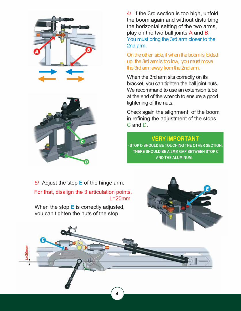
5/ Adjust the stop E of the hinge arm.
For that, disalign the 3 articulation points.L=20mm
When the stop E is correctly adjusted, you can tighten the nuts of the stop.
4/ If the 3rd section is too high, unfold the boom again and without disturbing the horizontal setting of the two arms, play on the two ball joints A and B. You must bring the 3rd arm closer to the 2nd arm.
On the other side, if when the boom is folded up, the 3rd arm is too low, you must move the 3rd arm away from the 2nd arm.
When the 3rd arm sits correctly on its bracket, you can tighten the ball joint nuts. We recommand to use an extension tube at the end of the wrench to ensure a good tightening of the nuts.
Check again the alignment of the boom in refining the adjustment of the stops C and D.
VERY IMPORTANT- STOP D SHOULD BE TOUCHING THE OTHER SECTION.
- THERE SHOULD BE A 2MM GAP BETWEEN STOP C
AND THE ALUMINUM.
5
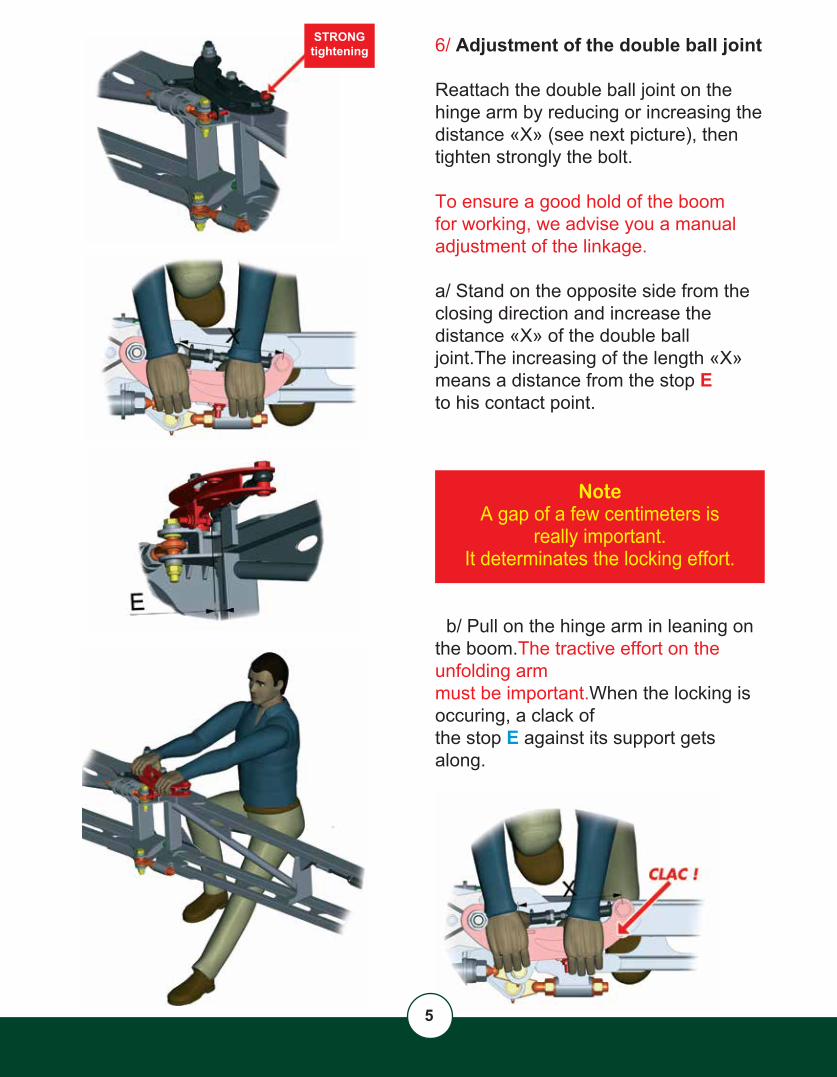
STRONGtightening 6/ Adjustment of the double ball joint
Reattach the double ball joint on the hinge arm by reducing or increasing the distance «X» (see next picture), then tighten strongly the bolt.
To ensure a good hold of the boom for working, we advise you a manual adjustment of the linkage.
a/ Stand on the opposite side from theclosing direction and increase the distance «X» of the double ball joint.The increasing of the length «X» means a distance from the stop E to his contact point.
NoteA gap of a few centimeters is
really important.It determinates the locking effort.
b/ Pull on the hinge arm in leaning on the boom.The tractive effort on the unfolding armmust be important.When the locking is occuring, a clack of the stop E against its support gets along.

6
Once the locking done, make sure again that the boom is well aligned, otherwise adjust again stops C and D.
c/ Unlock the hinge arm and increase thedistance «X» of the double ball joint abouthalf turn, then tighten very strongly the locknuts.
Tightening of the counternuts of the
double ball joint
STRONGtightening
Turn the cylinder rod couterclockwise with a flat wrenche
7/ Adjustment of the cylinder rod.
a/ Extend hydraulically to the maximum the cylinder rod and screw the ball joint to the maximum too.
b/ Reattach the cylinder rod on the hinge arm, tighten strongly the bolt.The stop E is no more in contact. Look at the gap between the stop and the head of the screw.
c/ Unscrew the ball joint in order to have the stop E in contact.For that, fold slightly hydraulically the 2nd section to access to the adjustment of the ball joint.Turn the cylinder rod in the anti-clockwisedirection.CAUTION!! Make it gradually.
Put again hydraulic pressure in the cylinder to unfold the boom.
7
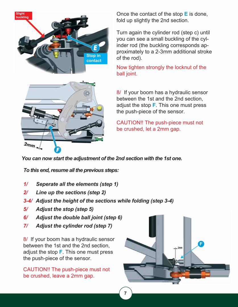
Slightbuckling
Stop in contact
You can now start the adjustment of the 2nd section with the 1st one.
To this end, resume all the previous steps:
1/ Seperate all the elements (step 1)2/ Line up the sections (step 2)3-4/ Adjust the height of the sections while folding (step 3-4)5/ Adjust the stop (step 5)6/ Adjust the double ball joint (step 6)7/ Adjust the cylinder rod (step 7)
Once the contact of the stop E is done,fold up slightly the 2nd section.
Turn again the cylinder rod (step c) until you can see a small buckling of the cyl-inder rod (the buckling corresponds ap-proximately to a 2-3mm additional stroke of the rod).
Now tighten strongly the locknut of theball joint.
8/ If your boom has a hydraulic sensorbetween the 1st and the 2nd section, adjust the stop F. This one must pressthe push-piece of the sensor.
CAUTION!! The push-piece must not be crushed, let a 2mm gap.
8/ If your boom has a hydraulic sensorbetween the 1st and the 2nd section, adjust the stop F. This one must pressthe push-piece of the sensor.
CAUTION!! The push-piece must not be crushed, leave a 2mm gap.
F

8
Maintenance & care of your aluminium boom
Weekly checks
Bolts and nuts checking
-Check that all the bolts and nuts are correctly tightened or tighten if necessary with suitable tools (wrench with 1 meter long extension bar).
Springs
-Check the tension of the breakaway spring. The tension of the spring is its zero state plus 100mm.
Lubrication-Lubrication of all linkage points (15 Lubrication points along the boom)and all ball joints and pin joints.

9
001-007 1001-933 2 Ball joint ring
001-602D 1001-602G 1P000-514 1P000-515 1 Low hex nut M30 200 left pitch
002-092 1P000-596 Hex nut M34 P000-704 2 Nord-lock washer Ø33 large
001-199001-601D 1001-601G 1P000-511 1P000-512 1 Low hex nut M20 150 left pitch
000-504 2 Hex nut M24 200 pitch001-232 1P000-701 2 Nord-lock washer Ø24 large
000-506 2 Hex nut M30 200 pitch001-234 1 Ball Joint Ø20 + Threaded rod M30x200P000-703 2 Nord-lock washer Ø30 large
001-968 1 TR4 / RHA / RHA3-B3 Beakaway hinge plateP000-178 4 HH Screw M8x30 deltatoneP000-538 4P000-797 4 Flat washer M8 deltatoneP000-833 4 Contact washer M8
003-629 1 Breakaway hinge angle reinforced TR4 / RHAP000-168 2 HH screw M8x25 deltatone DIN 933P000-177 2 Button screw M8 x 20 DIN 933P000-538 4 Lock nut M8 stainlessP000-833 6 Contact Washer M8
002-086 1
P000-500 2 Hex nut M12 deltatoneP000-795 2 Flat washer M12 deltatone
Part Nº Ref. Qty(s) DescriptionP000-513 1001-568 1 Cylinder seals kit for DA 50/30 S450 (for 002-599)001-577 1 Head bush DA 50/30002-492 1 Ball joint Ø25002-615 1 Piston DA 50/30002-596 1 Cylinder rod 50/30 S450 (for 002-599)
000-511 1 Low hex nut M20 150 right pitch001-552 1 Cylinder Seals Kit DA 40/25001-575 1 Head bush DA 40/25002-484 1 Ball joint Ø20 with anti-rotation plate002-588 1 Piston DA 40/25002-595 1 Cylinder rod 40/25 S460
15 002-599 28 010-007
16 002-598D
30 010-023
34 010-029
37 Ref. 010-090
32 010-026
29 010-016
31 010-024
35 010-030
2Ball joint Ø25 + Threaded rod M34 lg 210mm
Low hex nut M20 150 right pitchFemale ball Joint Ø20mm left threadFemale ball joint Ø20mm right threadThreaded rod RH/LH M20x1501
Low hex nut M30 200 right pitch Female ball joint Ø30 left threadFemale ball joint Ø30 right thread
Threaded rod RH/LH M30x200
Female ball joint Ø20 M24 lg:175
Lock nut M8 stainless
2
2
Spring hook threaded M12 (breakaway tension)
1/2 Low hex nut M24 200 right pitch
Part Nº Ref. Qty(s) Description
Part Nº Ref. Qty(s) Description
Part Nº Ref. Qty(s) Description
Part Nº Ref. Qty(s) DescriptionPart Nº Ref. Qty(s) Description
Part Nº Ref. Qty(s) DescriptionPart Nº Ref. Qty(s) Description
Part Nº Ref. Qty(s) DescriptionPart Nº Ref. Qty(s) Description
Ref.
Ref. Ref.
Ref.
Ref.
Ref.
Ref.
Ref. Ref.

10
OPTION : Sequential unfolding
Take car this support can be di�erent :Check on your boom
Rep. 5 3rd section support ( plastic + stop+ screws)
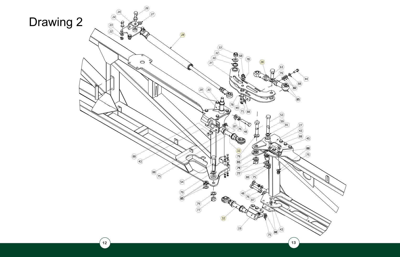
Drawing 2
Drawing 3
Drawing 4
2
1
1
2
3
4
3
5
67
8
9 10 11
1213
14
13
1516 17
18 19 20 21
11
12 13
Drawing 2 22
23
24
2526
27
28
29 30
3130
32
33

14 15
Drawing 356
78
41
40
16

16 17
Drawing 4

000-856 16 Rivet Ø4.8 lg 12mm000-865 1 Cotter pin Ø3.2 x 40 stainless000-924 1 Flange Ø50.8mm001-032 2 Plastic 1st arm RHA3-B3 boom001-033 1 Plastic cylinder support 80x40 x33001-090 2 Delrin washer Ø30.5int - Ø50ext thickness 3mm001-236 1 Round tube Ø28 lg 88 thickness 2001-237 1 Round tube Ø34 lg 98 thickness 2001-284 1001-482 1 End hydraulic stroke NF Banjo 1/4G (2nd/3trd section)001-484 1 End hydraulic switch V101 3/8 NF (1st/2nd Section)001-670 2 Ring Ø16.2/24 thickness 9.5 deltatone001-732 1 Ø10mm stainless axle for breakaway cable002-145 1 Baseplate light serie size 6 brute002-599 1 Cylinder Ø50/Ø30 stroke 450mm RHA3-B3 MS
002-598D 1 Right cylinder DA 40x25 S460 painted003-187 1 Cable + Reinforced sheath for breakaway003-325 1 Hinge axle for 3rd arm MS RHA3-B3 boom003-387 1 Lower articulation 1/2arm MS RHA3-B3 boom003-392 4 Ring Ø50x35.3 Thickness 5mm003-395 1003-504 1
003-314D 1 Cylinder attachement 1st arm right MS RHA3-B3 boom003-317D 1 RHA3-B3 MS right linkage shaft screed 1st section003-331D 1 RHA3-B3 MS right hinge arm 1st section003-342D 1 2nd section hinge arm003-379D 1 Right high link 2nd arm MS RHA3-B3 boom010-007 1 Double ball joint Ø30 with threaded rod lg 220mm010-016 1 Double ball joint Ø20 with threaded rod lg 160mm010-023 1010-024 1010-026 2010-028 2 Triangular rubber lg 150mm with screws010-029 1 TR4/RHA/RHA3-B3 breakaway hinge plate with screws010-030 1 TR4/RHA/RHA3-B3 breakaway hinge angle with screws010-031 1010-090 1 Complete breakaway spring hook010-107 1 RHA3-B3 2nd section support with screws
010-108D 1 RHA3-B3 3rd section support with screwsP020397 2 Steel ring Ø35 x Ø20.5 x 10P020398 2 Steel ring Ø40 x Ø20.5 x 7 P020475 1P000-004 26 HH screw M14x40 deltatone DIN 933P000-005 1 HH screw M14 x 45 deltatone DIN 933P000-006 2 HH screw M14 x 50 deltatone DIN 931 cl10,9P000-012 1 HH screw M20x60 deltatone DIN 933
18
Steel traction spring wire Ø7 Øext42 hooked lg 406mm
Ball joint Ø20 threaded rod M24 with screwsBall joint Ø20 threaded rod M30 + screwsBall joint Ø25 threaded rod M34 + screws
Ball joint Ø16mm with threaded rod M16 lg 100
Adjustable travel stopAnti-rotation for end hydraulic stroke
End travel stop
Part Nº Ref. Qty(s) Description
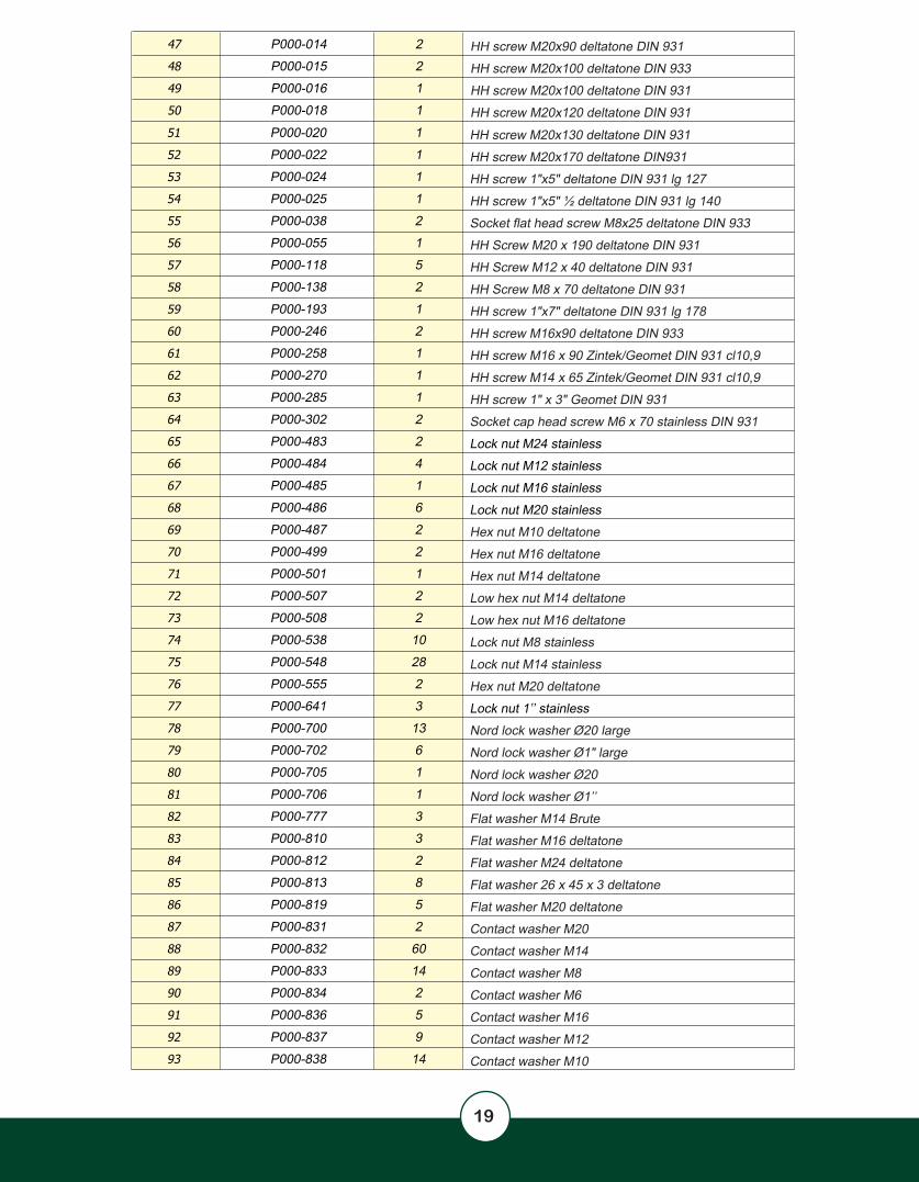
P000-020 1 HH screw M20x130 deltatone DIN 931P000-022 1 HH screw M20x170 deltatone DIN931P000-024 1 HH screw 1"x5" deltatone DIN 931 lg 127P000-025 1 HH screw 1"x5" ½ deltatone DIN 931 lg 140P000-038 2 Socket flat head screw M8x25 deltatone DIN 933P000-055 1 HH Screw M20 x 190 deltatone DIN 931P000-118 5 HH Screw M12 x 40 deltatone DIN 931P000-138 2 HH Screw M8 x 70 deltatone DIN 931P000-193 1 HH screw 1"x7" deltatone DIN 931 lg 178P000-246 2 HH screw M16x90 deltatone DIN 933P000-258 1 HH screw M16 x 90 Zintek/Geomet DIN 931 cl10,9P000-270 1 HH screw M14 x 65 Zintek/Geomet DIN 931 cl10,9 P000-285 1 HH screw 1" x 3" Geomet DIN 931P000-302 2 Socket cap head screw M6 x 70 stainless DIN 931 P000-483 2 Lock nut M24 stainlessP000-484 4 Lock nut M12 stainlessP000-485 1 Lock nut M16 stainless P000-486 6 Lock nut M20 stainless P000-487 2 Hex nut M10 deltatoneP000-499 2 Hex nut M16 deltatoneP000-501 1 Hex nut M14 deltatoneP000-507 2 Low hex nut M14 deltatoneP000-508 2 Low hex nut M16 deltatoneP000-538 10 Lock nut M8 stainlessP000-548 28 Lock nut M14 stainlessP000-555 2 Hex nut M20 deltatoneP000-641 3 Lock nut 1’’ stainlessP000-700 13 Nord lock washer Ø20 largeP000-702 6 Nord lock washer Ø1" largeP000-705 1 Nord lock washer Ø20P000-706 1 Nord lock washer Ø1’’P000-777 3 Flat washer M14 BruteP000-810 3 Flat washer M16 deltatoneP000-812 2 Flat washer M24 deltatoneP000-813 8 Flat washer 26 x 45 x 3 deltatoneP000-819 5 Flat washer M20 deltatoneP000-831 2 Contact washer M20P000-832 60 Contact washer M14P000-833 14 Contact washer M8P000-834 2 Contact washer M6P000-836 5 Contact washer M16P000-837 9 Contact washer M12P000-838 14 Contact washer M10
P000-014 2 HH screw M20x90 deltatone DIN 931P000-015 2 HH screw M20x100 deltatone DIN 933P000-016 1 HH screw M20x100 deltatone DIN 931P000-018 1 HH screw M20x120 deltatone DIN 931
19

www.pommier-america.com
2043 US HWY 34Leland, IL 60531
USA
Phone: (630) 486-5264
All our booms are designed and built using over 20 years knowledge and experience.
Pommier’s expertise and the quality of our products have made us a world-renowned designer and manufacturer of spray booms.
Since the first boom left our factory in 1986, we have delivered over 26,000 more to our customers.
Our expert designers and engineers work closely with our customers, and we tailorour booms to their machines in accordance with their requests and requirements.
Pommier also works with a large number of spray equipment manufacturers in the US, in France and worldwide.