rg series water source heat pump 0.75-6ton installation
TRANSCRIPT

RG SERIES0.75–6 TON
Issue Date: March 28, 2017
146.00-NOM1 02/10
RG
Ser
ies
Inst
alla
tion
Man
ual
RG SeriesCommercialGeothermal/ Water Source Heat Pump • R-410A Refrigerant • 0.75-6 Tons
Design Features
Factory Options
Accessories
Dimensional Data
Physical Data
Performance Data
Engineering Guide Specifications
R-410A
WATER SOURCE HEAT PUMP
INSTALLATION, OPERATION & MAINTENANCE Supersedes: 146.00-NOM1 (1013) Form 146.01-NOM1 (317)


RG SERIES INSTALLATION MANUAL
Table of Contents
Model Nomenclature . . . . . . . . . . . . . . . . . . . . . . . . . . . . . . . . . . . . . . . . . . . . . . . . . . . . . . . . . . . . . . 4
General Installation Information . . . . . . . . . . . . . . . . . . . . . . . . . . . . . . . . . . . . . . . . . . . . . . . . . . . . . . 5
Dimensional Data . . . . . . . . . . . . . . . . . . . . . . . . . . . . . . . . . . . . . . . . . . . . . . . . . . . . . . . . . . . . . . . . 6-9
Installing Horizontal Units . . . . . . . . . . . . . . . . . . . . . . . . . . . . . . . . . . . . . . . . . . . . . . . . . . . . . . . . . . 10
Hanger Bracket Locations . . . . . . . . . . . . . . . . . . . . . . . . . . . . . . . . . . . . . . . . . . . . . . . . . . . . . . . . . .11
Duct System and Water Piping. . . . . . . . . . . . . . . . . . . . . . . . . . . . . . . . . . . . . . . . . . . . . . . . . . . . . . 12
Condensate Drain. . . . . . . . . . . . . . . . . . . . . . . . . . . . . . . . . . . . . . . . . . . . . . . . . . . . . . . . . . . . . . . . 12
Water Quality . . . . . . . . . . . . . . . . . . . . . . . . . . . . . . . . . . . . . . . . . . . . . . . . . . . . . . . . . . . . . . . . . . . 13
System Cleaning and Flushing. . . . . . . . . . . . . . . . . . . . . . . . . . . . . . . . . . . . . . . . . . . . . . . . . . . . . . 14
Open Loop Ground Water Systems . . . . . . . . . . . . . . . . . . . . . . . . . . . . . . . . . . . . . . . . . . . . . . . . . . 15
Hot Water Generator Connections . . . . . . . . . . . . . . . . . . . . . . . . . . . . . . . . . . . . . . . . . . . . . . . . . 16-17
Freeze Detection . . . . . . . . . . . . . . . . . . . . . . . . . . . . . . . . . . . . . . . . . . . . . . . . . . . . . . . . . . . . . . . . 18
Electrical Connections . . . . . . . . . . . . . . . . . . . . . . . . . . . . . . . . . . . . . . . . . . . . . . . . . . . . . . . . . . . . 18
Electrical Data . . . . . . . . . . . . . . . . . . . . . . . . . . . . . . . . . . . . . . . . . . . . . . . . . . . . . . . . . . . . . . . . 19-21
Blower Performance Data . . . . . . . . . . . . . . . . . . . . . . . . . . . . . . . . . . . . . . . . . . . . . . . . . . . . . . . 22-27
Wiring Schematics . . . . . . . . . . . . . . . . . . . . . . . . . . . . . . . . . . . . . . . . . . . . . . . . . . . . . . . . . . . . . 28-31
Controls - Aurora Base Control. . . . . . . . . . . . . . . . . . . . . . . . . . . . . . . . . . . . . . . . . . . . . . . . . . . . 32-35
Unit Startup. . . . . . . . . . . . . . . . . . . . . . . . . . . . . . . . . . . . . . . . . . . . . . . . . . . . . . . . . . . . . . . . . . . . . 36
Operating Limits and Operating Parameters . . . . . . . . . . . . . . . . . . . . . . . . . . . . . . . . . . . . . . . . . . . 37
Pressure Drop . . . . . . . . . . . . . . . . . . . . . . . . . . . . . . . . . . . . . . . . . . . . . . . . . . . . . . . . . . . . . . . . . . 35
Reference Calculations and Legend . . . . . . . . . . . . . . . . . . . . . . . . . . . . . . . . . . . . . . . . . . . . . . . . . 38
Refrigerant Circuit Guideline . . . . . . . . . . . . . . . . . . . . . . . . . . . . . . . . . . . . . . . . . . . . . . . . . . . . . . . 39
Compressor and Thermistor Resistance . . . . . . . . . . . . . . . . . . . . . . . . . . . . . . . . . . . . . . . . . . . . . . 40
Heat of Extraction/Rejection Data . . . . . . . . . . . . . . . . . . . . . . . . . . . . . . . . . . . . . . . . . . . . . . . . . . . 41
Troubleshooting . . . . . . . . . . . . . . . . . . . . . . . . . . . . . . . . . . . . . . . . . . . . . . . . . . . . . . . . . . . . . . . . . 42
Startup/Troubleshooting Form . . . . . . . . . . . . . . . . . . . . . . . . . . . . . . . . . . . . . . . . . . . . . . . . . . . . 43-44
Preventive Maintenance. . . . . . . . . . . . . . . . . . . . . . . . . . . . . . . . . . . . . . . . . . . . . . . . . . . . . . . . . . . 45
Replacement Procedures. . . . . . . . . . . . . . . . . . . . . . . . . . . . . . . . . . . . . . . . . . . . . . . . . . . . . . . . . . 45
Service Parts . . . . . . . . . . . . . . . . . . . . . . . . . . . . . . . . . . . . . . . . . . . . . . . . . . . . . . . . . . . . . . . . . 46-47
Revision Guide . . . . . . . . . . . . . . . . . . . . . . . . . . . . . . . . . . . . . . . . . . . . . . . . . . . . . . . . . . . . . . . . . . 48

4
RG SERIES INSTALLATION MANUAL
Model NomenclatureRG SRG S1-2 4 5-7 8 9 10
Model Type RG – RG Series
Operation Range S – Single Stage
Cabinet Configuration V – Vertical H - Horizontal
Unit Capacity (MBTUH) 009, 012, 015, 018, 023 (horizontal), 024, 030, 036, 041 (vertical) 042, 048, 060, 070
Discharge Configuration T – Top (Vertical) E – End (Horizontal) S – Side (Horizontal)
Return Air Configuration L – Left R – Right
Voltage 0 – 208-230/60/1 2 – 265-277/60/1 (009-030) 3 – 208-230/60/3 (023-070) 4 – 460/60/3 (023-070) 5 – 575/60/3 (PSC Only 041-070)
Hot Wire Generator Option 0 – No HWG, No IntelliStart® 2 – HWG w/o pump, No IntelliStart (V015-070) 3 – No HWG, IntelliStart 5 – HWG w/o pump, IntelliStart (V024-070)
Blower Options 0 – PSC Blower 1 – Variable Speed ECM Blower (015-070) 2 – High Static Variable Speed ECM Blower (042-048) 3 – High Static PSC Blower (024, 030, 042, 048) 4 – 5-Speed ECM Blower (015-070)
Water Coil Option C – Copper N – CuproNickel
Sound Kit Option A – None B – Sound Kit (Not Available on H009-012)
Vintage * - Factory Use Only
Non-Standard Options SS – Standard
Drain Pan Option 0 – Composite, No Secondary Connection 1 – Composite, Secondary Connection 2 – Stainless Steel, No Secondary Connection 3 – Stainless Steel, Secondary Connection
Cabinet Option 0 – Unpainted, 1 in MERV 4, Filter Rail 1 – Painted, 1 in MERV 4, Filter Rail 2 – Unpainted, 2 in MERV 13, Filter Rail 3 – Painted, 2 in MERV 13, Filter Rail 4 – Unpainted, 1 in MERV 4, Filter Rack 5 – Painted, 1 in MERV 4, Filter Rack 6 – Unpainted, 2 in MERV 13, Filter Rack 7 – Painted, 2 in MERV 13, Filter Rack
Phase Guard N – No Phase Guard, No Disconnect P – Phase Guard, No Disconnect B – Phase Guard, Disconnect D – No Phase Guard, Disconnect
All-Aluminum Air Coil Option 5 – AlumiSealTM, Extended Range 6 – AlumiSeal, Standard Range 7 – No Coating, Extended Range 8 – No Coating, Standard Range Control Option A – AuroraTM Base Control (ABC) Z – AuroraTM with SMART Equipment DDC
Water Control Option N – None R – Water Flow Regulator (015-070) V – 2-Way Valve (015-070) B – 2-Way Valve w/ Water Flow Regulator (015-070)
Refrigeration Option N – None G – Hot Gas Bypass (015-072) R – Hot Gas Reheat (015-072) B – Hot Gas Bypass w/Hot Gas Reheat (015-072)
11 12 13 15V 036 T L 0 0 0 C A N
14N16
A17
ypeRG Series
on Rangengle Stag
Configurticalrizontal
pacity (M12, 015, 0orizontal)30, 036,ertical)48, 060, 0
ge Confip (Verticad (Horizo
de (Horizo
Air Confiftght
/1/1 /3 23SC
atoNo
umnteum
s
ege
rat
MBT01),
07
gual)onton
gu
518
N19
020
021
SS22-23
*24
eaS
M
3-C
o
mem
at
T8
0
u
tnt
u
Note: Phase Guard Only Available on 208-230/60/3 and 460/60/3 50VA Transformer with Aurora and 75VA Transformer with SMART Equipment
3
ed ECM Blower (015-070)ariable Speed ECM Blower (042-048)SC Blower (024, 030, 042, 048)
M Blower (015-070)
(009-030)(023-070)-070)
C Only 041
or OptionIntelliStart®
mp, No IntelliStart (V015-070)lliStart
mp, IntelliStart (V024-070)
tion
TUH) 8,
0
uration
tal)tal)
uration
1-070)

5
RG SERIES INSTALLATION MANUAL
WARNING: Before performing service or maintenance operations on a system, turn off main power switches to the indoor unit. If applicable, turn off the accessory heater power switch. Electrical shock could cause personal injury.
Installing and servicing heating and air conditioning equipment can be hazardous due to system pressure and electrical compo-nents. Only trained and qualified service personnel should install, repair or service heating and air conditioning equipment. Untrained personnel can perform the basic maintenance functions of clean-ing coils and cleaning and replacing filters. All other operations should be performed by trained service personnel. When working on heating and air conditioning equipment, observe precautions in the literature, tags and labels attached to the unit and other safety precautions that may apply.
Follow all safety codes. Wear safety glasses and work gloves. Use a quenching cloth for brazing operations and have a fire extin-guisher available.
Moving and StorageMove units in the normal “up” orientation. Horizontal units may be moved and stored per the information on the packaging. Do not stack more than three units in total height. Vertical units may be stored one upon another to a maximum height of two units. Do not attempt to move units while stacked. When the equipment is received, all items should be carefully checked against the bill of lading to be sure all crates and cartons have been received. Examine units for shipping damage, removing the units from the packaging if necessary. Units in question should also be internally inspected. If any damage is noted, the carrier should make the proper notation on the delivery receipt, acknowledging the damage.
Safety Considerations
General Installation Information
Vertical Unit Mounting
2 in. PEX Foam
Unit LocationLocate the unit in an indoor area that allows for easy removal of the filter and access panels. Location should have enough space for service personnel to perform maintenance or repair. Provide sufficient room to make water, electrical and duct connection(s). If the unit is located in a confined space, such as a closet, provisions must be made for return air to freely enter the space by means of a louvered door, etc. Any access panel screws that would be difficult to remove after the unit is installed should be removed prior to setting the unit. On horizontal units, allow adequate room below the unit for a condensate drain trap and do not locate the unit above supply piping. Care should be taken when units are located in unconditioned spaces to prevent damage from frozen water lines and excessive heat that could damage electrical components.
Installing Vertical UnitsPrior to setting the unit in place, remove and discard the compressor hold down shipping bolt located at the front of the compressor mounting bracket.
Vertical units are available in left or right air return configurations. Top flow vertical units should be mounted level on a vibration absorbing pad slightly larger than the base to provide isolation between the unit and the floor. It is not necessary to anchor the unit to the floor (see figure below).

6
RG SERIES INSTALLATION MANUAL
Vertical Dimensional Data
1
28
3
4
ACCESSPANEL
Air coil
AIR
CO
IL S
IDE A
IR C
OIL S
IDE
Air coil
5
Power supply1 in (25.4 mm)
knockout
Low voltage1/2" (12.7 mm)
knockout
Condensate3/4 in PVC
glue socket
FRONT FRONT
Right View - Right ReturnLeft View - Left Return
Air coil
5
Condensate 3/4 inPVC glue socket
1
2
3
4
6
87
87
86
Standard filter rails foropen return applications
Deluxe filter rack forductable return applications
2' (61 cm)Service Access Left Return
(Right Return opposite side)
2' (61 cm)AlternateService Access
Field installedduct flange
ACCESSPANEL
ACCESSPANEL
ACCESSPANEL
Front View - Left Return
Top View - Right Return Top View - Left Return
P
Q
B
RN
A
Front View - Right Return
U T
C
DE
H
F
G
1.4 in (3.5 cm)
1.6 in (4.1 cm)
W
V
1.6 in (4.1 cm)
DE
H
C
1.6 in(4.1 cm)1.6 in (4.1 cm)
L L KJ
1.4 in (3.5 cm)F
G
Q
P B
S N
M M
A
Isometric View - Left Return
K LLJ

7
RG SERIES INSTALLATION MANUAL
Vertical Dimensional Data cont.
LL
1.8 in.[4.6 cm]
AlternativePowerLocation
Disconnect Located on thisSide for a Right Return
DisconnectLocation
PowerSupply
Vertical Shown inLeft Return Configuration
VerticalModels
Overall Cabinet
Water Connections Electrical Knockouts1 2 3 4 5 6 7 8
A B C D E F G H Loop Knock-out J K L
Width Depth Height** In Out HWGIn HWG Out Cond-
ensateWater FPT
HWG Pro-visions
1/2 in. cond
1/2 in. cond
1 in. cond
009-012 in. 22.5 22.2 23.7 2.6 5.6 N/A N/A 8.8 1/2 N/A 7.4 3.4 5.4cm. 57.2 56.4 60.2 6.6 14.2 N/A N/A 22.4 12.7 mm N/A 18.8 8.6 13.7
015-018 in. 22.5 22.2 36.2 2.6 7.6 1.4 2.9 10.8 3/4 0.875 9.4 5.4 7.4cm. 57.2 56.4 91.9 6.6 19.3 3.6 7.4 27.4 19.1 mm 22.2 mm 23.9 13.7 18.8
024-030 in. 22.5 26.2 40.2 2.6 7.6 1.4 4.4 10.8 3/4 0.875 10.1 6.1 8.1cm. 57.2 66.5 102.1 6.6 19.3 3.6 11.2 27.4 19.1 mm 22.2 mm 25.7 15.5 20.6
036 in. 22.5 26.2 44.2 2.6 7.6 1.4 4.4 10.8 3/4 0.875 10.1 6.1 8.1cm. 57.2 66.5 112.3 6.6 19.3 3.6 11.2 27.4 19.1 mm 22.2 mm 25.7 15.5 20.6
041 in. 22.5 26.2 44.2 2.6 7.6 1.4 2.9 10.8 3/4 0.875 10.1 6.1 8.1cm. 57.2 66.5 112.3 6.6 19.3 3.6 7.4 27.4 19.1 mm 22.2 mm 25.7 15.5 20.6
042-048 in. 25.5 31.2 44.2 2.6 7.6 1.4 4.4 10.8 1 0.875 10.1 6.1 8.1cm. 64.8 79.2 112.3 6.6 19.3 3.6 11.2 27.4 25.4 mm 22.2 mm 25.7 15.5 20.6
060 in. 25.5 31.2 48.2 2.6 7.6 1.4 4.4 10.8 1 0.875 10.1 6.1 8.1cm. 64.8 79.2 122.4 6.6 19.3 3.6 11.2 27.4 25.4 mm 22.2 mm 25.7 15.5 20.6
070 in. 25.5 31.2 52.2 2.6 7.6 1.4 4.4 10.8 1 0.875 10.1 6.1 8.1cm. 64.8 79.2 132.6 6.6 19.3 3.6 11.2 27.4 25.4 mm 22.2 mm 25.7 15.5 20.6
VerticalModels
Discharge Connectionduct fl ange installed (±0.10 in)
Return Connection*using deluxe fi lter rack (±0.10 in)
M N P Q R S T U V WFilter Rack
WidthSupply Width
Supply Depth
Return Depth
Return Height
009-012 in. 2.2 10.0 10.0 6.1 9.4 9.4 2.1 18.1 10.0 1.9cm. 5.6 25.4 25.4 15.5 23.9 23.9 5.3 46.0 25.4 4.8
015-018 in. 2.2 14.0 14.0 4.1 4.3 7.7 2.1 18.1 20.0 1.9cm. 5.6 35.6 35.6 10.4 10.9 19.6 5.3 46.0 50.8 4.8
024-030 in. 2.2 14.0 14.0 6.1 4.5 7.7 2.1 22.1 22.1 1.9cm. 5.6 35.6 35.6 15.5 11.4 19.6 5.3 56.1 56.1 4.8
036 in. 2.2 14.0 14.0 6.1 4.5 7.7 2.1 22.1 26.1 1.9cm. 5.6 35.6 35.6 15.5 11.4 19.6 5.3 56.1 66.3 4.8
041 in. 2.2 18.0 18.0 4.1 3.9 3.9 2.1 22.1 26.1 1.9cm. 5.6 45.7 45.7 10.4 9.9 9.9 5.3 56.1 66.3 4.8
042-048 in. 2.2 18.0 18.0 6.6 4.6 6.3 1.6 28.1 26.0 2.0cm. 5.6 45.7 45.7 16.8 11.7 16.0 4.1 71.4 66.0 5.1
060 in. 2.2 18.0 18.0 6.6 4.6 6.3 1.6 28.1 30.0 2.0cm. 5.6 45.7 45.7 16.8 11.7 16.0 4.1 71.4 76.2 5.1
070 in. 2.2 18.0 18.0 6.6 4.6 6.3 1.6 28.1 34.0 2.0cm. 5.6 45.7 45.7 16.8 11.7 16.0 4.1 71.4 86.4 5.1
11/10/09Condensate is 3/4 in. PVC female glue socket and is switchable from side to front.*Dimensions for return connections are for the deluxe fi lter rack that is suitable for ducted return applications and extends 3.25 in. [8.26 cm] from the unit. The open fi lter rack, used in non-ducted returns, extends 2.2 in. [5.59 cm] from the unit.**Discharge fl ange is fi eld installed and extends 1 in. (25.4 mm) from top of cabinet.
Vertical Models LL009-012 Externally Mounted015-018 18.8 [47.8]024-030 14.3 [36.3]
036 15.3 [38.9]042-048 14.3 [36.3]
060 14.3 [36.3]070 14.3 [36.3]
Dimensions in inches [cm] 02/06/13
Vertical DisconnectWhen using disconnect, do not use dimension L from the standard vertical dimensional data. Use dimension LL from the vertical disconnect dimensional data.

8
RG SERIES INSTALLATION MANUAL
Horizontal Dimensional Data
Right Return End Discharge
Left ReturnEnd Discharge
End Discharge End Discharge
Side DischargeSide Discharge
Right Return Left ReturnFront
Front
CMP CMP
AP AP
Condensate"X" PVC size Condensate
"X" PVC size
RR Front View
BLOWEROUTLET
BLOWEROUTLET
Right Return Side Discharge Left Return Side Discharge
Right Return Side View Left Return Side View
FILTER RACK CONNECTION FILTER RACK CONNECTION
Front Front
Air Coil Air Coil
LR Front View
CP
CP
BLOWEROUTLET
BLOWEROUTLET
Front Front
CMP
AP
CMP
AP
AP
AP
AIR
CO
IL S
IDE A
IR C
OIL S
IDE
0.5 in. [1.3 cm] knockout1 in. [2.5 cm] knockout
1 in. [2.5 cm]knockout
0.5 in. [1.3 cm]knockout
BP
BP
FILT
ER
RA
CK FILTE
R R
AC
K
Standard filter railsStandard filter rails
Deluxe filter rack option shownDeluxe filter rack option shown
Deluxe filterrack option(shown)
BB
C C
L
M
NP
L
M
PN
A
L
M
PN
C
L
MC
A
P N
D
EJ
A
1.7 in.[5.3 cm]
1.7 in.[5.3 cm]
H
2.1 in. [5.3 cm] 2.1 in. [5.3 cm]
H
D
E K
J
K
1.7 1.7
J
K J
K
1.5 in. [3.8 cm]
SQ S QT
R
T
R
2.3 in. [5.8 cm]
Legend
AP = Alternate Service Panel
BP = Blower Service Panel
CP = Control Access Panel
CMP = Compressor Service Panel
2' (61 cm)Service Access
2' (61 cm)Service Access
0.5 in. [1.3 cm]knockout
1.5 in. [3.8 cm]
2.3 in.[5.8 cm]
1 in. [2.5 cm]knockout
0.5 in. [1.3 cm]knockout

9
RG SERIES INSTALLATION MANUAL
Horizontal Dimensional Data cont.
2.1 in.[5.3 cm]
KK
Disconnect Locatedon this Side for a
Left Return
DisconnectLocation
Power Supply
Horizontal Shown inRight Return Configuration
*Dimensions for return connections are for the deluxe fi lter rack that is suitable for ducted return applications and extends 3.25 in. [8.26 cm] from the unit. The open fi lter rack, used in non-ducted returns, extends 2.2 in. [5.59 cm] from the unit.Condensate 3/4 in. PVC stub extends from cabinet approximately 1-1/2 in. [38.1 mm]
HorizontalModels
Overall Cabinet
Water Connections Electrical Knockouts1 2 3 J K
A B C D E H Loop 1/2 in. cond 1 in. cond
Width Depth Height* In Out Cond-ensate Water FPT Low Voltage Power
Supply
009-012in. 19.2 30.9 11.9 1.8 4.8 0.8 1/2 4.5 4.5cm. 48.8 78.5 30.2 4.6 12.2 2.0 12.7 mm 11.4 11.4
015-023in. 22.5 42.0 17.2 1.8 6.8 0.8 3/4 7.1 7.1cm. 57.2 106.7 43.7 4.6 17.3 2.0 19.05 mm 18.0 18.0
024-030in. 22.5 42.0 19.2 1.8 6.8 0.8 3/4 9.2 7.1cm. 57.2 106.7 48.8 4.6 17.3 2.0 19.05 mm 23.4 18.0
036in. 22.5 45.0 19.2 1.8 6.8 0.8 3/4 9.2 7.1cm. 57.2 114.3 48.8 4.6 17.3 2.0 19.05 mm 23.4 18.0
042-048in. 25.5 48.0 21.2 1.8 6.8 0.8 1 9.2 9.1cm. 64.8 121.9 53.8 4.6 17.3 2.0 25.4 mm 23.4 23.1
060in. 25.5 53.0 21.2 1.8 6.8 0.8 1 9.2 9.1cm. 64.8 134.6 53.8 4.6 17.3 2.0 25.4 mm 23.4 23.1
070in. 25.5 61.0 21.2 1.8 6.8 0.8 1 9.2 9.1cm. 64.8 154.9 53.8 4.6 17.3 2.0 25.4 mm 23.4 23.1
HorizontalModels
Discharge Connectionduct fl ange installed (±0.10 in)
Return Connection*using deluxe fi lter rack option (±0.10 in) PVC Size
L M N P Q R S T XSupply Width Supply Depth Return Depth Return Height
009-012in. 2.3 8.0 10.0 2.3 15.4 9.4 3.0 1.4 1/2cm. 5.8 20.3 25.4 5.8 39.1 23.9 7.6 3.6 1.3
015-023in. 5.7 10.5 9.4 4.9 23.4 14.5 2.0 1.4 3/4cm. 14.5 26.7 23.9 12.4 59.4 36.8 5.1 3.6 1.9
024-030in. 6.7 10.5 9.4 4.9 27.4 16.4 2.0 1.5 3/4cm. 17.0 26.7 23.9 12.4 69.6 41.7 5.1 3.8 1.9
036in. 6.7 10.5 9.4 4.9 30.4 16.4 2.1 1.5 3/4cm. 17.0 26.7 23.9 12.4 77.2 41.7 5.3 3.8 1.9
042-048in. 4.9 13.6 13.2 4.6 35.4 18.6 2.4 1.5 3/4cm. 12.4 34.5 33.5 11.7 89.9 47.2 6.1 3.8 1.9
060in. 4.9 13.6 13.2 4.6 40.4 18.4 2.4 1.5 3/4cm. 12.4 34.5 33.5 11.7 102.6 46.7 6.1 3.8 1.9
070in. 4.9 13.6 13.2 4.6 45.6 18.6 2.3 1.5 3/4cm. 12.4 34.5 33.5 11.7 115.8 47.2 5.8 3.8 1.9
10/29/13
Horizontal Models KK009-012 Externally Mounted015-018 8.2 [20.8 ]024-030 9.2 [23.4]
036 9.2 [23.4]042-048 11.2 [28.4]
060 10.2 [25.9]070 11.2 [28.4]
Dimensions in inches [cm] 02/06/13
Horizontal DisconnectWhen using disconnect, do not use dimension K from the standard horizontal dimensional data. Use dimension KK from the horizontal disconnect dimensional data.

10
RG SERIES INSTALLATION MANUAL
Installing Horizontal UnitsRemove and discard the compressor hold down shipping bolt located at the front of the compressor mounting bracket prior to setting the unit in place. Horizontal units are available with side or end discharge.
NOTE: Left (Right) Return Side Discharge cannot be converted to Left (Right) Return End Discharge or vice versa, without additional custom sheet metal parts. Horizontal units are normally suspended from a ceiling by four (009-060 models) or five (070-072 models) 3/8 in. diameter threaded rods. The rods are usually attached to the unit by hanger bracket kits furnished with each unit.
Lay out the threaded rods per the Hanger Bracket Dimensions table. Assemble the hangers to the unit as shown. Securely tighten the brackets to the unit using the weld nuts located on the underside of the bottom panel. When attaching the hanger rods to the bracket, a double nut is required since vibration could loosen a single nut. To allow filter access, install hanger brackets as illustrated in the Hanger Bracket Locations section. The unit
should be pitched approximately 1/4 in. towards the drain in both directions to facilitate the removal of condensate. Use only the bolts provided in the kit to attach hanger brackets. The use of longer bolts could damage internal parts.
Some applications require the installation of horizontal units on an attic floor. In this case, the unit should be set in a full size secondary drain pan on top of a vibration absorbing pad. The secondary drain pan prevents possible condensate overflow or water leakage damage to the ceiling. The secondary drain pan is usually placed on a plywood base isolated from the ceiling joists by additional layers of vibration absorbing material.
CAUTION: Do not use rods smaller than 3/8 in. diameter since they may not be strong enough to support the unit. The rods must be securely anchored to the ceiling.
Installing Horizontal Units

11
RG SERIES INSTALLATION MANUAL
BC
A
E
D
G
F
Left
D
E
F
G
Right
Vibration Isolator
Washer
Hex Nuts(not supplied)
Bolt andLockwasher
3/8”Threaded Rod(not supplied)
CompressorSection
CompressorSection
Air HandlerSection
Air HandlerSection
Hanger DimensionsModel Hanger Kit
Part NumberUnit Hanger Dimensions
A B C
009-012in.
99S500A0431.7 21.8 18.1
cm [80.5] [55.4] [46.0]
015-023in.
99S500A0442.8 25.1 21.4
cm [108.6] [63.8] [54.4]
024-030in.
99S500A0442.8 25.1 21.4
cm [108.7] [63.8] [54.4]
036in.
99S500A0445.8 25.1 21.4
cm [116.3] [63.8] [54.4]
042-048in.
99S500A0448.8 28.1 24.4
cm [124.0] [71.4] [62.0]
060in.
99S500A0453.8 28.1 24.4
cm [136.7] [71.4] [62.0]
070in.
99S500A0461.8 28.1 24.4
cm [157.0] [71.4] [62.0]10/29/13
Weight DistributionModel
Vertical Shipping Weight
HorizontalShippingWeight
Horizontal Weight DistributionFront Back
D E F G
009lb. 110 120 46 23 26 25kg [50] [54] [21] [11] [12] [11]
012lb. 115 125 48 24 27 26kg [52] [57] [22] [11] [12] [12]
015lb. 165 175 67 34 37 36kg [75] [79] [31] [15] [17] [17]
018lb. 170 180 69 35 38 38kg [77] [82] [31] [16] [17] [17]
023lb. na 185 71 36 39 39kg na [84] [32] [16] [18] [17]
024lb. 230 245 94 47 52 51kg [104] [111] [43] [22] [24] [23]
030lb. 240 255 98 49 54 53kg [109] [116] [44] [22] [25] [24]
036lb. 265 285 110 55 61 59kg [120] [129] [50] [25] [28] [27]
041lb. 275 na na na na nakg [125] na na na na na
042lb. 285 300 115 58 64 63kg [129] [136] [52] [26] [29] [28]
048lb. 290 310 119 60 66 65kg [132] [141] [54] [27] [30] [29]
060lb. 335 360 138 70 77 75kg [152] [163] [63] [32] [35] [34]
070lb. 380 405 156 78 86 84kg [172] [184] [71] [36] [39] [38]
11/10/09
Hanger Bracket Locations

12
RG SERIES INSTALLATION MANUAL
An air outlet collar is provided on vertical top flow units and all horizontal units to facilitate a duct connection. A flexible connector is recommended for discharge and return air duct connections on metal duct systems. Uninsulated duct should be insulated with a minimum of 1-inch duct insulation. Application of the unit to uninsulated ductwork in an unconditioned space is not recommended as the unit’s performance will be adversely affected.
If the unit is connected to existing ductwork, check the duct system to ensure that it has the capacity to accommodate the air required for the unit application. If the duct is too small, as in the replacement of heating only systems, larger ductwork should be installed. All existing ductwork should be checked for leaks and repaired if necessary.
Duct System
Water Piping
The duct system should be sized to handle the design airflow quietly and efficiently. To maximize sound attenuation of the unit blower, the supply and return plenums should include an internal duct liner of fiberglass or constructed of ductboard for the first few feet. On systems employing a sheet metal duct system, canvas connectors should be used between the unit and the ductwork. If air noise or excessive airflow is a problem, the blower speed can be changed.
The proper water flow must be provided to each unit whenever the unit operates. To assure proper flow, use pressure/temperature ports to determine the flow rate. These ports should be located at the supply and return water connections on the unit. The proper flow rate cannot be accurately set without measuring the water pressure drop through the refrigerant-to-water heat exchanger.
All source water connections on commercial units are fittings that accept a male pipe thread (MPT). Insert the connectors by hand, then tighten the fitting with a wrench to provide a leakproof joint. When connecting to an open loop (groundwater) system, thread any copper MPT fitting into the connector and tighten in the same manner as described above.
1/2'' Pitch
Drain
Unit Pitch for DrainHorizontal Drain Connection (Composite Drain Pan)
Condensate DrainOn vertical units, the internal condensate drain assembly consists of a drain tube which is connected to the drain pan, a 3/4 in. PVC female adapter and a flexible connecting hose. The female adapter may exit either the front or the side of the cabinet. The adapter should be glued to the field-installed PVC condensate piping. On vertical units, a condensate hose is inside all cabinets as a trapping loop; therefore, an external trap is not necessary.
On horizontal units, a PVC stub or stainless steel tube is provided for condensate drain piping connection. An external trap is required (see below). If a vent is necessary, an open stand pipe may be applied to a tee in the field-installed condensate piping.
1.5 in. 1.5 in.PVC tube stub
PVC couplingVent (if needed)
PVC tube stub
1/8 in. per foot
NOTE: Check dimensional data for actual PVC sizes.

13
RG SERIES INSTALLATION MANUAL
In ground water situations where scaling could be heavy or where biological growth such as iron bacteria will be present, a closed loop system is recommended. The heat exchanger coils in ground water systems may, over a period of time, lose heat exchange capabilities due to a buildup of mineral deposits inside. These can be cleaned, but only by a qualified service mechanic, as special solutions and pumping equipment are required. Hot water generator coils can likewise become scaled and possibly plugged.
Water Quality
Material Copper 90/10 Cupronickel 316 Stainless SteelpH Acidity/Alkalinity 7 - 9 7 - 9 7 - 9
Scaling Calcium andMagnesium Carbonate
(Total Hardness)less than 350 ppm
(Total Hardness)less than 350 ppm
(Total Hardness)less than 350 ppm
Corrosion
Hydrogen Sulfide Less than 0.5 ppm (rotten egg smell appears at 0.5 ppm) 10 - 50 ppm Less than 1 ppm
Sulfates Less than 125 ppm Less than 125 ppm Less than 200 ppmChlorine Less than 0.5 ppm Less than 0.5 ppm Less than 0.5 ppmChlorides Less than 20 ppm Less than 125 ppm Less than 300 ppm
Carbon Dioxide Less than 50 ppm 10 - 50 ppm 10 - 50 ppmAmmonia Less than 2 ppm Less than 2 ppm Less than 20 ppm
Ammonia Chloride Less than 0.5 ppm Less than 0.5 ppm Less than 0.5 ppmAmmonia Nitrate Less than 0.5 ppm Less than 0.5 ppm Less than 0.5 ppm
Ammonia Hydroxide Less than 0.5 ppm Less than 0.5 ppm Less than 0.5 ppmAmmonia Sulfate Less than 0.5 ppm Less than 0.5 ppm Less than 0.5 ppm
Total Dissolved Solids (TDS) Less than 1000 ppm 1000 - 1500 ppm 1000 - 1500 ppmLSI Index +0.5 to -0.5 +0.5 to -0.5 +0.5 to -0.5
Iron Fouling(Biological Growth)
Iron, FE2+ (Ferrous)Bacterial Iron Potential < 0.2 ppm < 0.2 ppm < 0.2 ppm
Iron Oxide Less than 1 ppm, above this level deposition will occur
Less than 1 ppm, above this level deposition will occur
Less than 1 ppm, above this level deposition will occur
ErosionSuspended Solids Less than 10 ppm and filtered for
max. of 600 micron sizeLess than 10 ppm and filtered for
max. of 600 micron sizeLess than 10 ppm and filtered for
max. of 600 micron sizeThreshold Velocity
(Fresh Water) < 6 ft/sec < 6 ft/sec < 6 ft/sec
NOTES: Grains = ppm divided by 17mg/L is equivalent to ppm
2/22/12
In areas with extremely hard water, the owner should be informed that the heat exchanger may require occasional flushing. Failure to adhere to the guidelines in the water quality table could result in loss of warranty.
Units with cupronickel heat exchangers are recommended for open loop applications due to the increased resistance to build-up and corrosion, along with reduced wear caused by acid cleaning.

14
RG SERIES INSTALLATION MANUAL
System Cleaning and FlushingCleaning and FlushingPrior to start up of any heat pump, the water circulating system must be cleaned and flushed of all dirt and debris.
If the system is equipped with water shutoff valves, the supply and return runouts must be connected together at each unit location (This will prevent the introduction of dirt into the unit, see Flushing with Water Shutoff Valve Equipped Systems illustration). The system should be filled at the water make-up connection with all air vents open. After filling, vents should be closed.
The contractor should start the main circulator with the pressure reducing valve makeup open. Vents should be checked in sequence to bleed off any trapped air and to verify circulation through all components of the system.
As water circulates through the system, the contractor should check and repair any leaks found in the piping system. Drain(s) at the lowest point(s) in the system should be opened for initial flush and blowdown, making sure water fill valves are set at the same rate. Check the pressure gauge at the pump suction and manually adjust the make-up water valve to hold the same positive pressure both before and after opening the drain valves. Flushing should continue for at least two hours, or longer if required, until drain water is clean and clear.
The supplemental heater and/or circulator pump, if used, should be shut off. All drains and vents should be opened to completely drain the system. Short-circuited supply and return runouts should now be connected to the unit supply and return connections.
Refill the system with clean water. Test the system water for acidity and treat as required to leave the water slightly alkaline (pH 7.5 to 8.5). The specified percentage of antifreeze may also be added at this time. Use commercial grade antifreeze designed for HVAC systems only. Environol™ brand antifreeze is recommended.
Once the system has been filled with clean water and antifreeze (if used), precautions should be taken to protect the system from dirty water conditions. Dirty water will result in system-wide degradation of performance, and solids may clog valves, strainers, flow regulators, etc. Additionally, the heat exchanger may become clogged which reduces compressor service life and can cause premature unit failure.
In boiler/tower application, set the loop control panel set points to desired temperatures. Supply power to all motors and start the circulating pumps. After full flow has been established through all components including the heat rejector (regardless of season), air vented and loop temperatures stabilized, each of the units will be ready for check, test and start up and for air and water balancing.
Ground Source Loop System CheckoutOnce piping is completed between the unit pumping system and ground loop, final purging and charging of the loop is needed. A high pressure pump is needed to achieve adequate flow velocity in the loop to purge air and dirt particles from the loop itself. Antifreeze solution is used in most areas to prevent freezing. Flush the system adequately to remove as much air as possible; then pressurize the loop to a static pressure of 40-50 PSI (summer) or 50-75 PSI (winter). This is normally adequate for good system operation. Loop static pressure may decrease soon after initial installation, due to pipe expansion and loop temperature change. Running the unit for at least 30 minutes after the system has been completely purged of air will allow for the “break-in” period. It may be necessary to adjust static loop pressure (by adding water) after the unit has run for the first time. Loop static pressure will also fluctuate with the seasons. Pressures will be higher in the winter months than during the cooling season. This fluctuation is normal and should be considered when charging the system initially.
Ensure the pump provides adequate flow through the unit by checking pressure drop across the heat exchanger. Usually 2.25-3.0 gpm of flow per ton of cooling capacity is recommended in earth loop applications.
Return Runout
Supply Runout
Mains
Rubber Hose
Runouts InitiallyConnected Together
Flushing with Water Shutoff Valve Equipped Systems

15
RG SERIES INSTALLATION MANUAL
Typical open loop piping is shown below. Always maintain water pressure in the heat exchanger by placing water control valves at the outlet of the unit to prevent mineral precipitation. Use a closed, bladder-type expansion tank to minimize mineral formation due to air exposure. Insure proper water flow through the unit by checking pressure drop across the heat exchanger and comparing it to the figures in unit capacity data tables in the specification catalog. 1.5-2 gpm of flow per ton of cooling capacity is recommended in open loop applications. Due to only minor differences in flow rate from low to high, only one solenoid valve should be used. The valve should be sized for full flow.
Discharge water from the unit is not contaminated in any manner and can be disposed of in various ways, depending on local codes, i.e. recharge well, storm sewer, drain field, adjacent stream or pond, etc. Most local codes forbid the use of sanitary sewer for disposal. Consult your local building and zoning departments to assure compliance in your area.
Open System - Groundwater Application
FlexibleDuct Collar
VibrationAbsorbing Pad
P/T Plugs
Drain
Hot Water GeneratorConnections
Low Voltageto Thermostat
and Valve
Unit Supply
Aux. Heat Supply
Water Out
Water In
Shut Off Valves
Boiler DrainsFor HX Flushing
Disconnects(IfApplicable)
Rubber BladderExpansion Tank
SolenoidValve
Shut Off Valves(to isolate solenoid
valve while acid flushing)
Strainer
Flow ControlValve
(on outlet ofSolenoid Valve)
CompressorLine Voltage
Open Loop Ground Water Systems

16
RG SERIES INSTALLATION MANUAL
Hot Water Generator ConnectionsThe heat reclaiming hot water generator coil is of vented double-wall copper construction and is suitable for potable water.
To maximize the benefits of the hot water generator a minimum 50-gallon water heater is recommended. For higher demand applications, use an 80-gallon water heater or two 50-gallon water heaters connected in a series as shown below. Electric water heaters are recommended. Make sure all local electrical and plumbing codes are met for installing a hot water generator. A water softener is recommended with hard water (greater than 10 grains or 170 total hardness).
Typical Hot Water Generator Installation
Drain Valve
In
P/T ReliefValve
ColdWater In
HotWater Out
HWGWater In
HWGWater Out
Ball Valve
3/4 in. x 3/4 in. x 1/2 in. Tee
Vent
Field InstalledHWG Pump
CAUTION: Elements will burn out if energized dry.
Hot Water Generator Installation In Preheat Tank
In
Ball Valve
3/4 in. x 3/4 in. x 1/2 in. TeeCold
Water InHot
Water Out
P/T ReliefValve
P/T ReliefValve
HWGWater In
HWGWater Out
Drain Valve
Vent
Field InstalledHWG Pump
NOTE: This configuration maximizes hot watergenerator capability.
Water Tank PreparationTo install a unit with a hot water generator, follow these installation guidelines.
1. Turn off the power to the water heater.2. Attach a water hose to the water tank drain connection and run the
other end of the hose to an open drain or outdoors.3. Close the cold water inlet valve to the water heater tank.4. Drain the tank by opening the valve on the bottom of the tank, then
open the pressure relief valve or hot water faucet.5. Flush the tank by opening the cold water inlet valve to the water
heater to free the tank of sediments. Close when draining water is clear.
6. Disconnect the garden hose and remove the drain valve from the water heater.
7. Refer to Plumbing Installation and Hot WaterGenerator Startup.
Plumbing Installation1. Inspect the dip tube in the water heater cold inlet for a check
valve. If a check valve is present it must be removed or damage to the hot water generator circulator will occur.
2. Remove drain valve and fitting.3. Thread the 3/4-inch NPT x 3-1/2-inch brass nipple into the
water heater drain port.4. Attach the center port of the 3/4-inch FPT tee to the opposite
end of the brass nipple.5. Attach the 1/2-inch copper to 3/4-inch NPT adaptor to the side
of the tee closest to the unit. 6. Install the drain valve on the tee opposite the adaptor.7. Run interconnecting tubing from the tee to HWG
water out.8. Cut the cold water “IN” line going to the water heater.
9. Insert the reducing solder tee in line with cold water “IN” lineas shown.
10. Run interconnecting copper tubing between the unit DHW water “IN” and the tee (1/2-inch nominal). The recommended maximum distance is 50 feet.
11. To prevent air entrapment in the system, install a vent coupling at the highest point of the interconnecting lines.
12. Insulate all exposed surfaces of both connecting water lines with 3/8-inch wall closed cell insulation.
NOTE: All plumbing and piping connections must comply with local plumbing codes.

17
RG SERIES INSTALLATION MANUAL
Hot Water Generator Connections cont.
CAUTION: Never operate the HWG circulating pump while dry. If the unit is placed in operation before the hot water generator piping is connected, be sure that the pump wires are disconnected from the contactor.
Hot Water Generator Startup1. Make sure the power is off to the heat pump. Connect the wire
from the hot water generator pump to T1 on the contactor.2. Close the drain valve to the water heater.3. Open the cold water supply to the tank.4. Open a hot water faucet in the building to bleed air from the
system. Close when full.5. Open the pressure relief valve to bleed any remaining air from
the tank, then close.6. If so equipped, turn the venting (burping) screw in the center of
the pump two (2) turns open (water will drip out), wait until all air is purged from the pump, then tighten the plug. Use vent couplings to bleed air from the lines.
7. Carefully inspect all plumbing for water leaks and correctas required.
8. Before restoring electrical supply to the water heater, adjust the temperature setting on the tank.
• On tanks with both upper and lower elements, the lower element should be turned down to the lowest setting, approximately 100°F. The upper element should be adjusted to 120°F to 130°F. Depending upon the specific needs of the customer, you may want to adjust the upper element differently.
• On tanks with a single element, lower the thermostat setting to 120°F.
9. After the thermostat(s) is adjusted, replace the access cover and restore electrical supply to the water heater.
10. Make sure that any valves in the hot water generator circuitare open.
11. Turn on the unit to heating. 12. The HWG pump should be running. When the pump is first
started, turn the venting (burping) screw (if equipped) in the center of the pump two (2) turns open until water dribbles out, then replace. Allow the pump to run for at least five minutes to ensure that water has filled the circulator properly.
13. The temperature difference between the water entering and leaving the hot water generator should be 5°F to 15°F. The water flow should be approximately 0.4 gpm per ton of nominal cooling.
14. Allow the unit to heat water for 15 to 20 minutes to be sure operation is normal.

18
RG SERIES INSTALLATION MANUAL
GeneralBe sure the available power is the same voltage and phase as that shown on the unit serial plate. Line and low voltage wiring must be done in accordance with local codes or the National Electric Code, whichever is applicable.
Power ConnectionConnect the incoming line voltage wires to L1 and L2 of the con-tactor for single-phase unit. Consult the Electrical Data tables for correct fuse sizes.
Electrical Connections208 Volt OperationAll RG Series 208/230 units are factory wired for 230 volt opera-tion. For 208 volt operation, the red and blue transformer wires must be switched on terminal strip PS.
CAUTION: When installing a unit with an variable speed ECM blower motor in 460/60/3 voltage, a neutral wire is required to allow proper unit operation.
For Aurora Base Control, set SW2-1, FP1, on the printed circuit board for applications using a closed loop antifreeze solution to 15°F [-9.4°C]. On applications using an open loop/ground water system (or closed loop no antifreeze), set this dip switch to 30°F [-1.1°C], the factory default setting. (Refer to the Dip Switch Field Selection table).
Freeze Detection
Aurora Base Control Box

19
RG SERIES INSTALLATION MANUAL
Electrical DataPSC Motor
HACR circuit breaker in USA only* With optional high-static PSC motor** With optional IntelliStartTM
NOTE: High-static option not available on all model sizes.
Model RatedVoltage
VoltageMin/Max
Compressor BlowerMotorFLA
TotalUnitFLA
MinCircAmp
MaxFuse/HACRMCC RLA LRA LRA**
009 208-230/60/1 187/253 6.4 4.1 21.0 n/a 0.6 4.7 5.7 10/15265/60/1 238/292 6.7 4.3 22.0 n/a 0.6 4.9 6.0 10/15
012 208-230/60/1 187/253 7.7 4.9 25.0 n/a 0.6 5.5 6.7 10/15265/60/1 238/292 7.0 4.5 22.0 n/a 0.6 5.1 6.2 10/15
015 208-230/60/1 187/253 9.2 5.9 29.0 n/a 1.1 7.0 8.5 10/15265/60/1 238/292 7.8 5.0 28.0 n/a 1.0 6.0 7.2 10/15
018 208-230/60/1 187/253 10.4 6.7 33.5 13.4 1.1 7.8 9.5 15265/60/1 238/292 8.7 5.6 28.0 n/a 1.0 6.6 8.0 10/15
023
208-230/60/1 187/253 21.0 13.5 58.3 23.3 1.2 14.7 18.1 30265/60/1 238/292 14.0 9.0 54.0 n/a 1.1 10.1 12.4 20
208-230/60/3 187/253 11.0 7.1 55.0 33.0 1.2 8.3 10.1 15460/60/3 414/506 5.5 3.5 28.0 16.8 0.6 4.1 5.0 10/15
024
208-230/60/1 187/253 21.0 13.5 58.3 23.3 1.2 14.7 18.1 30265/60/1 238/292 14.0 9.0 54.0 n/a 1.1 10.1 12.4 20
208-230/60/3 187/253 11.0 7.1 55.0 33.0 1.2 8.3 10.1 15460/60/3 414/506 5.5 3.5 28.0 16.8 0.6 4.1 5.0 10/15
024*
208-230/60/1 187/253 21.0 13.5 58.3 23.3 1.5 15.0 18.4 30265/60/1 238/292 14.0 9.0 54.0 n/a 1.5 10.5 12.8 20
208-230/60/3 187/253 11.0 7.1 55.0 33.0 1.5 8.6 10.4 15460/60/3 414/506 5.5 3.5 28.0 16.8 1.0 4.5 5.4 10/15
030
208-230/60/1 187/253 22.0 14.1 73.0 29.2 1.5 15.6 19.1 30265/60/1 238/292 17.5 11.2 60.0 n/a 1.5 12.7 15.5 25
208-230/60/3 187/253 13.9 8.9 58.0 34.8 1.5 10.4 12.6 20460/60/3 414/506 6.5 4.2 28.0 16.8 1.0 5.2 6.3 10/15
030*
208-230/60/1 187/253 22.0 14.1 73.0 29.2 2.2 16.3 19.8 30265/60/1 238/292 17.5 11.2 60.0 n/a 2.0 13.2 16.0 25
208-230/60/3 187/253 13.9 8.9 58.0 34.8 2.2 11.1 13.3 20460/60/3 414/506 6.5 4.2 28.0 16.8 1.1 5.3 6.4 10/15
036
208-230/60/1 187/253 27.0 17.3 96.7 38.7 2.2 19.5 23.8 40265/60/1 238/292 19.0 12.2 72.0 n/a 1.1 13.3 16.3 20
208-230/60/3 187/253 20.0 12.8 95.0 57.0 2.2 15.0 18.2 30460/60/3 414/506 10.0 6.4 45.0 27.0 1.1 7.5 9.1 15
041
208-230/60/1 187/253 31.0 20.0 115.0 46.0 3.5 23.5 28.5 45208-230/60/3 187/253 20.0 12.8 95.0 57.0 3.5 16.3 19.5 30
460/60/3 414/506 10.0 6.4 45.0 27.0 1.8 8.2 9.8 15575/60/3 517/633 8.5 5.4 38.0 n/a 1.4 6.8 8.2 10/15
042
208-230/60/1 187/253 31.0 20.0 115.0 46.0 3.5 23.5 28.5 45208-230/60/3 187/253 20.0 12.8 95.0 57.0 3.5 16.3 19.5 30
460/60/3 414/506 10.0 6.4 45.0 27.0 1.8 8.2 9.8 15575/60/3 517/633 8.5 5.4 38.0 n/a 1.4 6.8 8.2 10/15
042*
208-230/60/1 187/253 31.0 20.0 115.0 46.0 4.6 24.6 29.6 45208-230/60/3 187/253 20.0 12.8 95.0 57.0 4.6 17.4 20.6 30
460/60/3 414/506 10.0 6.4 45.0 27.0 2.3 8.7 10.3 15575/60/3 517/633 8.5 5.4 38.0 n/a 1.9 7.3 8.7 10/15
048208-230/60/1 187/253 32.0 21.0 115.0 46.0 3.5 24.5 29.8 50208-230/60/3 187/253 25.0 16.0 115.0 69.0 3.5 19.5 23.5 35
460/60/3 414/506 12.0 7.7 50.0 30.0 1.8 9.5 11.4 15
048*
208-230/60/1 187/253 32.0 21.0 115.0 46.0 4.6 25.6 30.9 50208-230/60/3 187/253 25.0 16.0 115.0 69.0 4.6 20.6 24.6 40
460/60/3 414/506 12.0 7.7 50.0 30.0 2.3 10.0 11.9 15575/60/3 517/633 10.0 6.4 40.0 n/a 1.9 8.3 9.9 15
060
208-230/60/1 187/253 41.0 26.3 150.0 60.0 5.9 32.3 38.8 60208-230/60/3 187/253 27.5 17.6 120.0 72.0 5.9 23.5 27.9 45
460/60/3 414/506 13.0 8.3 70.0 42.0 3.0 11.3 13.4 20575/60/3 517/633 11.5 7.4 53.0 n/a 1.9 9.3 11.2 15
070
208-230/60/1 187/253 47.0 30.1 145.0 58.0 5.9 36.0 43.5 70208-230/60/3 187/253 28.0 17.3 120.0 72.0 5.9 23.2 27.5 40
460/60/3 414/506 15.0 9.6 70.0 42.0 3.0 12.6 15.0 20575/60/3 517/633 12.5 8.0 53.0 n/a 1.9 9.9 11.9 15
05/21/13

20
RG SERIES INSTALLATION MANUAL
Electrical Data cont.5-Speed ECM Motor
HACR circuit breaker in USA only** With optional IntelliStartTM
Model Rated Voltage VoltageMin/Max
Compressor BlowerMotorFLA
TotalUnitFLA
MinCircAmp
MaxFuse/HACRMCC RLA LRA LRA**
015 208-230/60/1 187/253 9.2 5.9 29.0 n/a 4.1 10.0 11.5 15265/60/1 238/292 7.8 5.0 28.0 n/a 3.6 8.6 9.9 10/15
018 208-230/60/1 187/253 10.4 6.7 33.5 13.4 4.1 10.8 12.5 15265/60/1 238/292 8.7 5.6 28.0 n/a 3.6 9.2 10.6 15
023
208-230/60/1 187/253 21.0 13.5 58.3 23.3 4.1 17.6 21.0 30265/60/1 238/292 14.0 9.0 54.0 n/a 3.6 12.6 14.9 20
208-230/60/3 187/253 11.0 7.1 55.0 33.0 4.1 11.2 13.0 20460/60/3 414/506 5.5 3.5 28.0 16.8 2.1 5.6 6.5 10/15
024
208-230/60/1 187/253 21.0 13.5 58.3 23.3 4.1 17.6 21.0 30265/60/1 238/292 14.0 9.0 54.0 n/a 3.6 12.6 14.9 20
208-230/60/3 187/253 11.0 7.1 55.0 33.0 4.1 11.2 13.0 20460/60/3 414/506 5.5 3.5 28.0 16.8 2.1 5.6 6.5 10/15
030
208-230/60/1 187/253 22.0 14.1 73.0 29.2 4.1 18.2 21.7 35265/60/1 238/292 17.5 11.2 60.0 n/a 3.6 14.8 17.6 25
208-230/60/3 187/253 13.9 8.9 58.0 34.8 4.1 13.0 15.2 20460/60/3 414/506 6.5 4.2 28.0 16.8 2.1 6.3 7.4 10/15
036
208-230/60/1 187/253 27.0 17.3 96.7 38.7 4.1 21.4 25.7 40265/60/1 238/292 19.0 12.2 72.0 n/a 3.6 15.8 18.9 30
208-230/60/3 187/253 20.0 12.8 95.0 57.0 4.1 16.9 20.1 30460/60/3 414/506 10.0 6.4 45.0 27.0 2.1 8.5 10.1 15
041208-230/60/1 187/253 31.0 20.0 115.0 46.0 7.6 27.6 32.6 50208-230/60/3 187/253 20.0 12.8 95.0 57.0 7.6 20.4 23.6 30
460/60/3 414/506 10.0 6.4 45.0 27.0 4.0 10.4 12.0 15
042208-230/60/1 187/253 31.0 20.0 115.0 46.0 7.6 27.6 32.6 50208-230/60/3 187/253 20.0 12.8 95.0 57.0 7.6 20.4 23.6 30
460/60/3 414/506 10.0 6.4 45.0 27.0 4.0 10.4 12.0 15
048208-230/60/1 187/253 32.0 21.0 115.0 46.0 7.6 28.6 33.9 50208-230/60/3 187/253 25.0 16.0 115.0 69.0 7.6 23.6 27.6 40
460/60/3 414/506 12.0 7.7 50.0 30.0 4.0 11.7 13.6 20
060208-230/60/1 187/253 41.0 26.3 150.0 60.0 7.6 33.9 40.5 60208-230/60/3 187/253 27.5 17.6 120.0 72.0 7.6 25.2 29.6 45
460/60/3 414/506 13.0 8.3 70.0 42.0 4.0 12.3 14.4 25
070208-230/60/1 187/253 47.0 30.1 145.0 58.0 7.6 37.7 45.2 70208-230/60/3 187/253 28.0 17.3 120.0 72.0 7.6 24.9 29.2 45
460/60/3 414/506 15.0 9.6 70.0 42.0 4.0 13.6 16.0 2505/21/13

21
RG SERIES INSTALLATION MANUAL
Electrical Data cont.Variable Speed ECM Motor
CAUTION: When installing a unit with a variable speed ECM blower motor in 460/60/3 voltage, a neutral wire is required to allow proper unit operation.
HACR circuit breaker in USA only* With optional 1 HP ECM motor** With optional IntelliStartTM
Model RatedVoltage
VoltageMin/Max
Compressor BlowerMotorFLA
TotalUnitFLA
MinCircAmp
MaxFuse/HACRMCC RLA LRA LRA**
015 208-230/60/1 187/253 9.2 5.9 29.0 n/a 4.0 9.9 11.4 15265/60/1 238/292 7.8 5.0 28.0 n/a 4.1 9.1 10.3 15
018 208-230/60/1 187/253 10.4 6.7 33.5 13.4 4.0 10.7 12.4 15265/60/1 238/292 8.7 5.6 28.0 n/a 4.1 9.7 11.1 15
023
208-230/60/1 187/253 21.0 13.5 58.3 23.3 4.0 17.5 20.9 30265/60/1 238/292 14.0 9.0 54.0 n/a 4.1 13.1 15.4 20
208-230/60/3 187/253 11.0 7.1 55.0 33.0 4.0 11.1 12.9 15460/60/3 414/506 5.5 3.5 28.0 16.8 4.1 7.6 8.5 10/15
024
208-230/60/1 187/253 21.0 13.5 58.3 23.3 4.0 17.5 20.9 30265/60/1 238/292 14.0 9.0 54.0 n/a 4.1 13.1 15.4 20
208-230/60/3 187/253 11.0 7.1 55.0 33.0 4.0 11.1 12.9 15460/60/3 414/506 5.5 3.5 28.0 16.8 4.1 7.6 8.5 10/15
030
208-230/60/1 187/253 22.0 14.1 73.0 29.2 4.0 18.1 21.6 35265/60/1 238/292 17.5 11.2 60.0 n/a 4.1 15.3 18.1 25
208-230/60/3 187/253 13.9 8.9 58.0 34.8 4.0 12.9 15.1 20460/60/3 414/506 6.5 4.2 28.0 16.8 4.1 8.3 9.4 10/15
036
208-230/60/1 187/253 27.0 17.3 96.7 38.7 4.0 21.3 25.6 40265/60/1 238/292 19.0 12.2 72.0 n/a 4.1 16.3 19.3 30
208-230/60/3 187/253 20.0 12.8 95.0 57.0 4.0 16.8 20.0 30460/60/3 414/506 10.0 6.4 45.0 27.0 4.1 10.5 12.1 15
041208-230/60/1 187/253 31.0 20.0 115.0 46.0 4.0 24.0 29.0 45208-230/60/3 187/253 20.0 12.8 95.0 57.0 4.0 16.8 20.0 30
460/60/3 414/506 10.0 6.4 45.0 27.0 4.1 10.5 12.1 15
042208-230/60/1 187/253 31.0 20.0 115.0 46.0 4.0 24.0 29.0 45208-230/60/3 187/253 20.0 12.8 95.0 57.0 4.0 16.8 20.0 30
460/60/3 414/506 10.0 6.4 45.0 27.0 4.1 10.5 12.1 15
042*208-230/60/1 187/253 31.0 20.0 115.0 46.0 7.0 27.0 32.0 50208-230/60/3 187/253 20.0 12.8 95.0 57.0 7.0 19.8 23.0 35
460/60/3 414/506 10.0 6.4 45.0 27.0 6.9 13.3 14.9 20
048208-230/60/1 187/253 32.0 21.0 115.0 46.0 4.0 25.0 30.3 50208-230/60/3 187/253 25.0 16.0 115.0 69.0 4.0 20.0 24.0 40
460/60/3 414/506 12.0 7.7 50.0 30.0 4.1 11.8 13.7 20
048*208-230/60/1 187/253 32.0 21.0 115.0 46.0 7.0 28.0 33.3 50208-230/60/3 187/253 25.0 16.0 115.0 69.0 7.0 23.0 27.0 40
460/60/3 414/506 12.0 7.7 50.0 30.0 6.9 14.6 16.5 20
060208-230/60/1 187/253 41.0 26.3 150.0 60.0 7.0 33.3 39.9 60208-230/60/3 187/253 27.5 17.6 120.0 72.0 7.0 24.6 29.0 45
460/60/3 414/506 13.0 8.3 70.0 42.0 6.9 15.2 17.3 25
070208-230/60/1 187/253 47.0 30.1 145.0 58.0 7.0 37.1 44.6 70208-230/60/3 187/253 28.0 17.3 120.0 72.0 7.0 24.9 29.4 45
460/60/3 414/506 15.0 9.6 70.0 42.0 6.9 16.5 18.9 2505/21/13

22
RG SERIES INSTALLATION MANUAL
Blower Performance DataStandard PSC Motor
Optional High Static PSC Motor
Model BlowerSpd
BlowerSize
Motorhp
Airfl ow (cfm) at External Static Pressure (in. wg)0 0.05 0.10 0.15 0.20 0.25 0.30 0.35 0.40 0.45 0.50 0.60 0.70 0.80 0.90 1.00
009
H
6 x 8 1/10
530 515 500 485 470 450 430 405 385 355 330 - - - - -MH 475 460 450 435 420 405 385 365 345 320 300 - - - - -ML* 435 420 410 395 380 365 345 325 300 - - - - - - -
L 370 355 340 325 310 290 275 - - - - - - - - -
012
H
6 x 8 1/10
530 515 500 485 470 450 430 405 385 355 330 - - - - -MH* 475 460 450 435 420 405 385 365 345 320 300 - - - - -ML 435 420 410 395 380 365 345 325 300 - - - - - - -L 370 355 340 325 310 290 275 - - - - - - - - -
015H
9 x 7 1/6875 860 845 830 820 805 790 770 750 725 700 - - - - -
M 760 750 740 730 720 710 700 680 660 640 620 - - - - -L 630 620 610 600 590 580 570 560 550 520 490 - - - - -
018H
9 x 7 1/6875 860 845 830 820 805 790 770 750 725 700 - - - - -
M 760 750 740 730 720 710 700 680 660 640 620 - - - - -L 630 620 610 600 590 580 570 560 550 520 490 - - - - -
023H
9 x 7 1/51020 990 960 930 900 870 850 830 800 770 690 - - - - -
M 960 840 820 800 780 760 740 720 690 670 - - - - - -L 720 700 680 650 640 620 600 580 570 550 - - - - - -
024H
9 x 7 1/51065 1045 1030 1005 975 950 925 900 870 835 800 - - - - -
M 880 865 850 830 815 795 775 750 725 700 670 - - - - -L 805 790 780 765 745 725 710 685 660 630 600 - - - - -
030H
9 x 7 1/31240 1220 1200 1175 1150 1110 1080 1055 1030 975 920 840 730 - - -
M 1095 1085 1080 1060 1045 1020 995 960 925 885 850 785 675 - - -L 860 860 855 850 850 845 845 825 805 775 750 680 - - - -
036H
9 x 7 1/21360 1340 1320 1290 1260 1220 1185 1130 1080 1045 1010 910 855 - - -
M 1205 1190 1170 1145 1120 1085 1050 1015 980 940 900 845 - - - -L 1070 1060 1050 1035 1020 995 970 940 910 875 840 780 - - - -
041H
10x10 1/21655 1635 1615 1590 1570 1535 1500 1425 1350 1270 1185 1080 970 - - -
M 1470 1455 1445 1425 1410 1380 1350 1285 1240 1205 1170 905 - - - -L 1150 1140 1130 1110 1090 1050 1010 970 930 900 865 800 - - - -
042H
10 x 10 1/21705 1685 1665 1645 1625 1595 1565 1530 1500 1450 1405 1260 1140 - - -
M 1485 1475 1465 1445 1430 1410 1390 1350 1315 1260 1210 1110 1010 - - -L 1180 1165 1150 1135 1120 1090 1060 1030 1000 965 920 855 - - - -
048H
10 x 10 1/21930 1910 1885 1860 1830 1790 1750 1710 1665 1620 1580 1280 1235 - - -
M 1580 1565 1550 1535 1525 1505 1485 1445 1410 1310 1215 1130 1030 - - -L 1180 1170 1160 1140 1120 1100 1080 1050 1020 970 930 875 - - - -
060H
11 x 10 12360 2330 2300 2270 2240 2215 2190 2160 2130 2095 2060 1985 1920 1855 - -
M 2165 2130 2095 2070 2050 2030 2010 1985 1965 1930 1900 1850 1775 1700 - -L 1965 1940 1920 1900 1885 1870 1855 1825 1800 1780 1760 1720 1625 1530 - -
070H
11 x 10 12450 2435 2420 2395 2370 2340 2310 2280 2250 2225 2200 2040 2000 1950 - -
M 2215 2190 2170 2155 2140 2120 2095 2070 2045 2015 1990 1940 1876 1795 - -L 2005 1990 1975 1960 1950 1940 1925 1910 1890 1865 1845 1780 1710 1565 - -
7/6/10
Model BlowerSpd
BlowerSize
Motorhp
Airfl ow (cfm) at External Static Pressure (in. wg)0 0.05 0.10 0.15 0.20 0.25 0.30 0.35 0.40 0.45 0.50 0.60 0.70 0.80 0.90 1.00
024H
9 x 7 1/31240 1220 1200 1175 1150 1110 1080 1055 1030 975 920 840 730 - - -
M 1095 1085 1080 1060 1045 1020 995 960 925 885 850 785 675 - - -L 860 860 855 850 850 845 845 825 805 775 750 680 - - - -
030H
9 x 7 1/21340 1320 1300 1270 1240 1200 1160 1115 1070 1025 985 880 - - - -
M 1185 1175 1165 1130 1095 1065 1035 1000 965 920 880 795 - - - -L 1050 1040 1030 1015 1000 980 960 925 895 855 815 - - - - -
042H
10 x 10 3/42095 2080 2060 2020 1980 1950 1920 1880 1840 1780 1725 1550 1335 1120 - -
M 1960 1940 1920 1890 1865 1830 1800 1760 1725 1670 1620 1435 1300 - - -L 1800 1780 1760 1740 1725 1695 1670 1625 1585 1525 1465 1300 1200 - - -
048H
10 x 10 3/42095 2080 2060 2020 1980 1950 1920 1880 1840 1780 1725 1550 1335 1120 - -
M 1960 1940 1920 1890 1865 1830 1800 1760 1725 1670 1620 1435 1300 - - -L 1800 1780 1760 1740 1725 1695 1670 1625 1585 1525 1465 1300 1200 - - -
7/6/10
Factory settings are in BoldAirfl ow values are with dry coil and standard fi lterFor wet coil performance fi rst calculate the face velocity of the air coil (Face Velocity [fpm] = Airfl ow [cfm] / Face Area [sq ft]). Then for velocities of 200 fpm reduce the static capability by 0.03 in. wg, 300 fpm by 0.08 in. wg, 400 fpm by 0.12in. wg. and 500 fpm by 0.16 in. wg.
Factory settings are in BoldAirfl ow values are with dry coil and standard fi lterFor wet coil performance fi rst calculate the face velocity of the air coil (Face Velocity [fpm] = Airfl ow [cfm] / Face Area [sq ft]). Then for velocities of 200 fpm reduce the static capability by 0.03 in. wg, 300 fpm by 0.08 in. wg, 400 fpm by 0.12in. wg. and 500 fpm by 0.16 in. wg.* Setting for 265 V operation.
23
RG SERIES INSTALLATION MANUAL
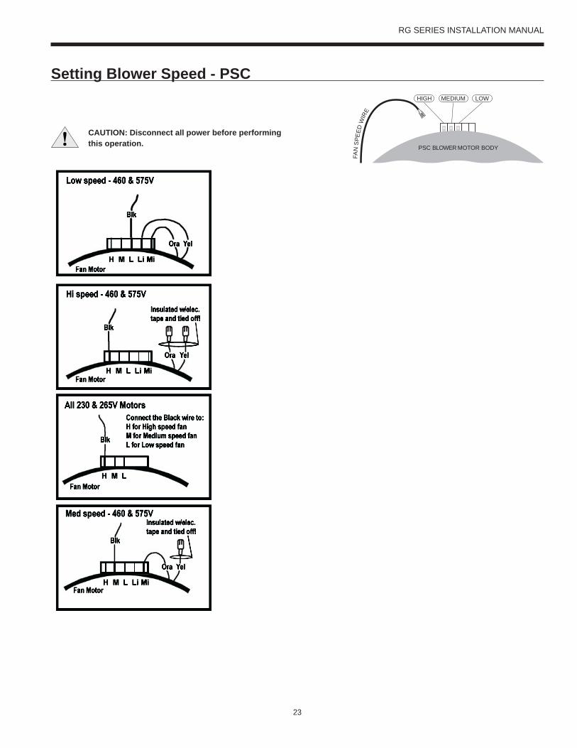
Setting Blower Speed - PSC
CAUTION: Disconnect all power before performingthis operation. PSC BLOWER MOTOR BODY
HIGH LOWMEDIUM
FAN
SPE
EDW
IRE

24
RG SERIES INSTALLATION MANUAL
Blower Performance Data cont.5-Speed ECM Motor
Factory settings are in BoldAirfl ow values are with dry coil and standard 1 in. fi lterISO/AHRI rating point on the US*070 will require moving the red wire on the motor to high speed (tap 5) and disconnecting the tan wire from tap 5.
5-Speed ECM Motor Connections
CAUTION: Disconnect all power before performing this operation.
Setting Blower Speed - 5-Speed ECM5-speed ECM blower motors have fi ve (5) speeds of which three (3) are selectable on single speed and four (4) are selectable on dual capacity.
Model Motor Speed
Motor Tap
Blower Size
Motor HP
Airflow (cfm) at External Static Pressure (in. wg)0 0.05 0.10 0.15 0.20 0.25 0.30 0.35 0.40 0.45 0.50 0.60 0.70 0.80 0.90 1.00
015
High 5
9 x 7 1/2
915 895 880 865 850 830 815 805 795 775 750 730 695 640 - -Med High 4 805 785 765 750 740 725 705 685 665 655 635 605 535 - - -
Med 3 725 715 700 680 660 635 615 600 585 560 535 485 - - - -Med Low 2 695 675 650 630 610 590 575 550 525 490 455 - - - - -
Low 1 655 600 550 530 508 490 475 435 395 350 - - - - - -
018
High 5
9 x 7 1/2
915 895 880 865 850 830 815 805 795 775 750 730 695 640 - -Med High 4 805 785 765 750 740 725 705 685 665 655 635 605 535 - - -
Med 3 725 715 700 680 660 635 615 600 585 560 535 485 - - - -Med Low 2 695 675 650 630 610 590 575 550 525 490 455 - - - - -
Low 1 655 600 550 530 508 490 475 435 395 350 - - - - - -
023
High 5
9 x 7 1/2
980 960 940 930 920 905 890 875 860 840 820 800 745 - - -Med High 4 890 878 865 845 825 813 800 785 770 753 735 710 665 - - -
Med 3 830 815 800 788 775 755 735 723 710 690 670 640 600 - - -Med Low 2 780 760 740 703 665 653 640 620 600 585 570 - - - - -
Low 1 625 593 560 535 510 495 480 455 430 410 390 - - - - -
024
High 5
9 x 7 1/2
980 960 940 930 920 905 890 875 860 840 820 800 745 - - -Med High 4 890 878 865 845 825 813 800 785 770 753 735 710 665 - - -
Med 3 830 815 800 788 775 755 735 723 710 690 670 640 600 - - -Med Low 2 780 760 740 703 665 653 640 620 600 585 570 - - - - -
Low 1 625 593 560 535 510 495 480 455 430 410 390 - - - - -
030
High 5
9 x 7 1/2
1340 1310 1280 1240 1200 1170 1140 1095 1050 1015 980 900 800 - - -Med High 4 1130 1115 1100 1085 1070 1057 1044 1022 1000 970 940 870 780 - - -
Med 3 1030 1005 980 965 950 935 920 900 880 870 860 830 750 - - -Med Low 2 960 945 930 915 900 885 870 855 840 825 810 790 740 - - -
Low 1 790 765 740 725 710 690 670 660 650 630 610 580 500 - - -
036
High 5
9 x 7 1/2
1370 1345 1320 1285 1250 1220 1190 1158 1125 1085 1045 960 - - - -Med High 4 1265 1253 1240 1220 1200 1175 1150 1120 1090 1053 1015 - - - - -
Med 3 1160 1143 1125 1113 1100 1085 1070 1055 1040 1020 1000 - - - - -Med Low 2 1110 1095 1080 1065 1050 1038 1025 1008 990 980 970 - - - - -
Low 1 825 803 780 770 760 740 720 705 690 670 650 - - - - -
041
High 5
11 x 10 1
1840 1825 1810 1790 1770 1745 1720 1700 1680 1660 1640 1600 1570 1530 1480 -Med High 4 1730 1713 1695 1670 1645 1623 1600 1575 1550 1535 1520 1480 1440 1390 1350 -
Med 3 1630 1610 1590 1563 1535 1513 1490 1470 1450 1425 1400 1370 1330 1290 - -Med Low 2 1550 1520 1490 1465 1440 1415 1390 1370 1350 1330 1310 1260 1220 1180 - -
Low 1 1380 1340 1300 1275 1250 1225 1200 1175 1150 1125 1100 1030 980 820 - -
042
High 5
11 x 10 1
1840 1825 1810 1790 1770 1745 1720 1700 1680 1660 1640 1600 1570 1530 1480 -Med High 4 1730 1713 1695 1670 1645 1623 1600 1575 1550 1535 1520 1480 1440 1390 1350 -
Med 3 1630 1610 1590 1563 1535 1513 1490 1470 1450 1425 1400 1370 1330 1290 - -Med Low 2 1550 1520 1490 1465 1440 1415 1390 1370 1350 1330 1310 1260 1220 1180 - -
Low 1 1380 1340 1300 1275 1250 1225 1200 1175 1150 1125 1100 1030 980 820 - -
048
High 5
11 x 10 1
2060 2045 2030 2015 2000 1970 1940 1925 1910 1890 1870 1830 1800 1750 1740 -Med High 4 1880 1860 1840 1825 1810 1785 1760 1740 1720 1705 1690 1640 1610 1570 1535 -
Med 3 1790 1770 1750 1730 1710 1685 1660 1640 1620 1600 1580 1550 1510 1460 - -Med Low 2 1670 1650 1630 1605 1580 1555 1530 1510 1490 1470 1450 1410 1370 1340 - -
Low 1 1430 1405 1380 1353 1325 1303 1280 1255 1230 1210 1190 1130 1070 925 - -
060
High 5
11 x 10 1
2400 2360 2330 2315 2300 2290 2285 2275 2265 2250 2230 2200 2165 2110 2080 2030Med High 4 2180 2160 2140 2130 2120 2105 2090 2075 2060 2045 2030 2000 1960 1930 1890 1850
Med 3 2080 2050 2020 2010 2000 1985 1970 1955 1940 1925 1910 1870 1840 1800 1760 1720Med Low 2 1930 1920 1910 1893 1875 1863 1850 1833 1815 1798 1780 1740 1700 1660 1620 1590
Low 1 1750 1735 1720 1698 1675 1658 1640 1620 1600 1583 1565 1525 1490 1450 1410 1350
070
High 5
11 x 10 1
2400 2360 2330 2315 2300 2290 2285 2275 2265 2250 2230 2200 2165 2110 2080 2030Med High 4 2180 2160 2140 2130 2120 2105 2090 2075 2060 2045 2030 2000 1960 1930 1890 1850
Med 3 2080 2050 2020 2010 2000 1985 1970 1955 1940 1925 1910 1870 1840 1800 1760 1720Med Low 2 1930 1920 1910 1893 1875 1863 1850 1833 1815 1798 1780 1740 1700 1660 1620 1590
Low 1 1750 1735 1720 1698 1675 1658 1640 1620 1600 1583 1565 1525 1490 1450 1410 135001/23/13

25
RG SERIES INSTALLATION MANUAL
The 5-speed ECM is a ‘Constant Torque’ ECM motor and delivers air flow similar to a PSC but operates as efficiently as an variable speed ECM motor. Because it’s an ECM Motor, the 5-speed ECM can ramp slowly up or down like the variable speed ECM motor. There are 5 possible speed taps available on the 5-speed motor with #1 being the lowest airflow and #5 being the highest airflow. These speed selections are preset at the time of manufacture and are easily changed in the field if necessary.
5-Speed ECM Benefits: - High efficiency - Soft start - 5 speeds with up to 4 speeds on-line - Built in logic allows air flow to change with G, Y1, Y2
and W signals - Super efficient low airflow continuous blower
setting (G)
If more than one tap are energized at the same time, built in logic gives precedence to the highest tap number and allows air flow to change with G, Y1, Y2 and W signals. Each of those 5 speeds has a specific ‘Torque’ value programmed into the motor for each speed selection. As static pressure increases, airflow decreases resulting in less torque on the rotor. The motor responds only to changes in torque and adjusts its speed accordingly.
The 5-speed motor is powered by line voltage but the motor speed is energized by 24VAC.
Power Connection - 3/16 in. quick connects - Line 1 (orange wire) to L, Ground (green wire) to G, Line 2 (for 208V-230V units) to N (brown wire).
Signal Connection - 1/4 in. quick connects - Common to C, 24VAC to Taps #1-5.
Applying 24VAC power between any of the motor taps 1-5 (1/4 in. quick connects) and common will signal the motor to run and regulate torque at the programmed level. The tap input voltage must be in the range 12-33VAC. The 5-speed ECM will have less variation over the operating static pressure range versus a PSC motor as well as a significant watts reduction due to the high motor efficiency.
Thermal Protection - Motor is electronically protected.
Locked Rotor Amps - If motor speed decreases below a programmed stall speed, the motor will shut down and after a delay period, the control will attempt to restart the motor.
The 5-speed ECM speed tap selections are as follows:The blue wire should be placed on the speed tap desired for the (G) continuous blower setting – factory wired to Tap 1.
The red wire should be placed on the speed tap desired during compressor operation (Y1 signal) – factory wired to Tap 3 or 4.
The gray wire is not factory wired to the motor and is tied to the wire harness. It is field connected and can be used with 3ht/2cl thermostats or IntelliZone to deliver the required air flow for the Y2 signal.
The tan wire should be placed on the speed tap desired for auxiliary heat (W signal) – factory wired to Tap 5.
5-Speed ECM Contant Torque Motors
26
RG SERIES INSTALLATION MANUAL
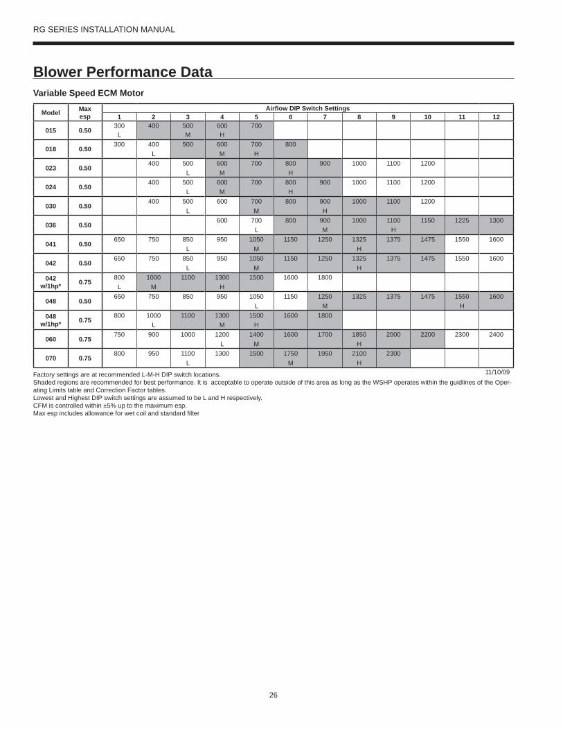
Blower Performance Data Variable Speed ECM Motor
Model Maxesp
Airfl ow DIP Switch Settings1 2 3 4 5 6 7 8 9 10 11 12
015 0.50300 400 500 600 700
L M H
018 0.50300 400 500 600 700 800
L M H
023 0.50400 500 600 700 800 900 1000 1100 1200
L M H
024 0.50400 500 600 700 800 900 1000 1100 1200
L M H
030 0.50400 500 600 700 800 900 1000 1100 1200
L M H
036 0.50600 700 800 900 1000 1100 1150 1225 1300
L M H
041 0.50650 750 850 950 1050 1150 1250 1325 1375 1475 1550 1600
L M H
042 0.50650 750 850 950 1050 1150 1250 1325 1375 1475 1550 1600
L M H042
w/1hp* 0.75800 1000 1100 1300 1500 1600 1800
L M H
048 0.50650 750 850 950 1050 1150 1250 1325 1375 1475 1550 1600
L M H048
w/1hp* 0.75800 1000 1100 1300 1500 1600 1800
L M H
060 0.75750 900 1000 1200 1400 1600 1700 1850 2000 2200 2300 2400
L M H
070 0.75800 950 1100 1300 1500 1750 1950 2100 2300
L M H11/10/09Factory settings are at recommended L-M-H DIP switch locations.
Shaded regions are recommended for best performance. It is acceptable to operate outside of this area as long as the WSHP operates within the guidlines of the Oper-ating Limits table and Correction Factor tables.Lowest and Highest DIP switch settings are assumed to be L and H respectively.CFM is controlled within ±5% up to the maximum esp.Max esp includes allowance for wet coil and standard fi lter

27
RG SERIES INSTALLATION MANUAL
Blower Performance Data cont.
The ABC board’s Yellow Confi g LED will fl ash the current variable speed ECM blower speed selections for low, med, and high continuously with a short pause in between. The speeds can also be confi rmed with the AID Tool under the Setup/ECM Setup screen. The variable speed ECM blower motor speeds can be fi eld adjusted with or without using an AID Tool.
Variable Speed ECM Setup without an AID ToolThe blower speeds for Low (G only), Med (Y1), and High (Y2/Aux) can be adjusted directly at the Aurora ABC board which utilizes the push button (SW1) on the ABC board. This procedure is outlined in the Variable Speed ECM Confi guration Mode portion of the Aurora ‘Base’ Control System section.
Variable Speed ECM Setup with an AID ToolA much easier method utilizes the AID Tool to change the airfl ow using the procedure below. First navigate to the Setup screen and then select ECM Setup. This screen displays the current variable speed ECM settings. It allows the technician to enter the setup screens to change the variable speed ECM settings. Change the highlighted item using the ◄ and ► buttons and then press the ◙ button to select the item.
Setting Blower Speed - Variable Speed ECM
Variable Speed ECM Speed Setup - These screens allow the technician to select the low, medium, and high blower speed for the variable speed ECM blower motor. Change the highlighted item using the ▲ and ▼ buttons. Press the ◙
button to select the speed.
After the high speed setting is selected the AID Tool will automatically transfer back to the ECM Setup screen.
Variable Speed ECM Setup with an AID Tool cont.Selecting YES will enter variable speed ECM speed setup, while selecting NO will return to the previous screen.
ECM SPEED INFO
LOW SPEED: 3MED SPEED: 5HIGH SPEED: 7
WANT TO CHANGE?
YESOPTION ◄►
NOENTER ◙
ECM SPEED INFO
12 <– LOW3456789101112
OPTION ◄► ENTER ◙
ECM SPEED INFO
12 LOW345 <– MED6789101112
OPTION ◄► ENTER ◙
ECM SPEED INFO
12 LOW345 MED6789101112 <– HIGH
OPTION ◄► ENTER ◙

28
RG SERIES INSTALLATION MANUAL
Wiring SchematicsCommercial Aurora with PSC Motor 208-230-265/60/1
Compressor
Cap
L1L2
CCT1T2
Transformer
H M LP3
PSCBlowerMotor
GrnWhtBrn
Cap3 AirflowSettings
C
R
S
Black
White
Black
Blue230V265V
Black
Black
Tan
Red
Red208VNote 2
Blue
1 3RB
Note 1
Black (95)
Red (97)
DisconnectNeutralGround
L1 L1
L2 L2
L3 L3
Unit Power Supply208-230-265/60/1
G
Green (93)
RB CC
470Ω
470ΩResistor
White (12)
Black (13)
Violet (14)
Black (15)
Orange (01)
Orange (02)
Condensate
Brown (23)
Black/White
Green
Yellow Black/White
Yellow
2 1 3
IsolationValve
Red (51)
Green (50)
White (52)
Note 3
Note 3
RV
HPLP
T
FDRV
Blue (07)
Blue (08)
Black (09)
Black (10)
Yellow
Yellow
Red (53)
24V
CFM
P13
P4
SW1
P5JW2
P9
LO
O/B
Y2WDH
P8 P7
RS485 NET RS485 NET
P6
RS485 EXP
P3
SW2
On
Future Use L Output Type
CC – Dual/SingleAcc – Dip 5Acc – Dip 4
RV – B/OFP2 – 15°F/30°FFP1 – 15°F/30°F
Com1LED5
Com2LED5
Test Mode
F1-3A
P1
C
PWM
12345678
ALMALGACC COMACC NOACC NC
RC
GY1
EH2CEH1CCOC R - +C R - +
Off
FaultLED1
R
StatusLED3
ConfigLED2
CC2 CC F C R F FG CC CCGCC2HI
CC2LO
CC2G REV REV FP1 FP1 FP2 FP2 LPS LPS HPS HPS
Aurora Base Control(ABC)
K1-RV Relay
K2-CC Relay
K3-CC2 Relay
K4-Fan RelayK5-Alarm Relay
K6-Acc Relay
F
R
C
CCGY1C
R
ESLS
P2
EH1
YG G
G

29
RG SERIES INSTALLATION MANUAL
Page 1
Thermistor
Relay Coil
Switch - Condensate Overflow
Switch - High pressure
Switch - Low pressure
Polarized connector
Factory Low Voltage WiringFactory Line Voltage WiringField Low Voltage WiringField Line Voltage WiringOptional BlockDC Voltage PCB Traces
Internal JunctionQuick Connect Terminal
Field Wiring Lug
Ground
Relay Contacts – N.O., N.C.
Field Zone Sensor Wiring
Legend
L1
Capacitor
T
123
CC – Compressor ContactorCO – Condensate Overflow SensorES – Emergency ShutdownHP – High Pressure SwitchLP – Low Pressure SwitchFD – Freeze Detection SensorF1 – Fuse
1 – Optional, factory installed unit mounted disconnect.2 – Swap blue and red leads for 208V operation.3 – Optional, factory installed internal isolation valve.
Notes:
Slow FlashFast FlashFlash Code
Status LED (LED1, Green)Configuration LED (LED2, Yellow)Fault LED (LED3, Red)
Status LED (LED1, Green)Normal ModeControl is Non-FunctionalTest ModeLockout ActiveDehumidification ModeReservedReservedLoad ShedESD
1 second on and 1 second off
Random Start DelayFast Flash
OFFON
Slow FlashFast Flash
Flash Code 2Flash Code 3
Flash Code 6
Flash Code 4Flash Code 5
Aurora LED Flash Codes
100 milliseconds on and 100 milliseconds off100 milliseconds on and 400 milliseconds off with a 2 second pause before repeating
Reserved Flash Code 7
Configuration LED (LED2, Yellow) Fault LED (LED3, Red)
Fast FlashFast Flash
No Software Overide Flash ECM SettingDIP Switch Overide Slow Flash
Normal ModeInput Fault LockoutHigh Pressure LockoutLow Pressure Lockout
Low Water Coil Limit Lockout - FP1Low Air Coil Limit Lockout - FP2
ReservedCondensate Overflow LockoutOver/Under Voltage ShutdownReservedReservedAir/Water Coil Limit Sensor Error
Flash Code 1OFF
Flash Code 2Flash Code 3Flash Code 4Flash Code 5
Flash Code 8
Flash Code 6Flash Code 7
Flash Code 9Flash Code 10Flash Code 11
ECM Configure Mode Fast FlashReset Configure Mode Off
Fuse
SW1 – Push buttonSW2 – DIP package 8 positionRB – Blower RelayRV – Reversing Valve Coil
Accessory Relay
Cycle with BlowerCycle with CompressorWater Valve Slow OpenOutdoor Air Damper
SW2-4 SW2-5On OnOff OffOn OffOff On
Operation
Light Emitting Diode - GreenG
Light Emitting Diode - YellowY
Light Emitting Diode - RedR
Event Normal Mode Test ModeRandom Start DelayCompressor On DelayCompressor Minimum On TimeCompressor Short Cycle DelayBlower Off DelayFault Recognition Delay – High PressureStart-Up Bypass – Low PressureFault Recognition Delay – Low PressureStart-Up Bypass – Low Water/Air Coil LimitFault Recognition Delay – Low Water/Air Coil LimitFault Recognition Delay – Condensate OverflowThermostat Call Recognition TimeAuxiliary Heat Staging DelayEmergency Heat Staging Delay
Less than 1 second
5 to 80 seconds 1 second5 seconds < 1 second
30 seconds 2 secondsLess than 1 second
2 minutes 5 seconds4 minutes 15 seconds
2 minutes
2 minutes
30 seconds30 seconds 30 seconds
30 seconds30 seconds
30 seconds30 seconds30 seconds
2 seconds 2 seconds5 minutes2 minutes
20 seconds7.5 seconds
Aurora Timing Events
Reheat Delay 30 seconds 30 secondsWater Valve Slow Open Delay 90 seconds 90 seconds
CC2
EH1
Facto
ry
Fault
ALG
ALMLSES ACC
c
Status
AURORA BASE CONTROL™
RV – K1
CC2
CC – K2
CC Hi – K3
Fan – K4
Alarm – K5
Acc – K6
ACC
no
ACC
nc
O/BCRLO G Y1 Y2 W DH
3A-F
use
O/BCRLO G Y1 Y2 W DH
LOG
HICCGCCFGFR
HPHPLP
FP2FP2FP1
REVREV
CFM
PWM
ECM PWM
Facto
ry
Factory Fan Connection
R R
CC
C
C
R
(-)
(+)
RS 48
5
EH2C
EH1C
CO
(+)(-)RCRS
485 E
xpFa
ctory
Com1
Com2
Config
G
G
G
YR
SW1 Test
FP1 – 15oF/30oF
JW2 - Alarm
P11
P5
P2 P1
P8
P7
P9
P6
P3
SW2
P13P4 FP2 – 15oF/30oF
RV – B/O
ACC – Dip 4
ACC – Dip 5
CC – Dual/Single
L – Pulse/Continuous
Reheat/Normal
Facto
ry Us
e
Field ConnectionsField Connections
C
LP
FP1
F
CC
G
Y1
1
2
3
4
5
6
7
8
Off On
N/ARS
485 N
ET
LED3
LED2LED1

30
RG SERIES INSTALLATION MANUAL
Wiring Schematics cont.Commercial Aurora Base with X13 Motor - 460/60/3
Transfo rmer
Blue460V
Black
24V
Red (51)
Green (50)
White (52)
Note 2Red (53)
CC
470
470Resistor
Violet (14)Black (15)
Orange (01)Orange (02)
Condensate
Brown (23)Green
RV
HPLP
T
FDRV
Blue (07)
Blue (08)Black (09)Black (10)
YellowYellow
Blue460V
Black
Yellow
L2L3
CCT2T3
L1
T1
T1
T2
T3
Black
Yellow
Red
L1 L2 L3
Phase Guard Monitor (PGM)
C
Y-OUTY
PGM
Black (7)White (8)
Red (9)
Yellow (91)Black/White (92)
Black (95)
Yellow (96)
DisconnectNeutralGround
L1 L1
L2 L2
L3 L3
Unit Power Supply460/60/3G
Green (93)
Red (97)
123
LN
G
X13Fan
Motor
C45
Green
Orange
Brown
Tan (31)Gray (30)
Blue (33)Red (32)
Black (35)
Black/White
Black/White
Yellow
LED4 LED5
GG
UltraTech
Dual Capacity
Units Only
RCP
CS
Blue(16)Blue(18)
CFM
P13
P4
SW1
P5JW2
P9
LO
O/B
Y2WDH
P8 P7
RS485 NET RS485 NET
P6
RS485 EXP
P3
SW2
On
Future Use L Output Type
CC – Dual/SingleAcc – Dip 5Acc – Dip 4
RV – B/OFP2 – 15°F/30°FFP1 – 15°F/30°F
Com1LED5
Com2LED5
Test Mode
F1-3A
P1
C
PWM
12345678
ALMALGACC COMACC NOACC NC
RC
GY1
EH2CEH1CCOC R - +C R - +
Off
Faul tLED1
R
StatusLED3
ConfigLED2
CC2 CC F C R F FG CC CCGCC2HI
CC2LO
CC2G REVREVFP1 FP1 FP2 FP2 LPS LPSHPSHPS
Aurora Base Control(ABC)
K1-RV Relay
K2-CC Relay
K3-CC2 Relay
K4-Fan RelayK5-Alarm Relay
K6-Acc Relay
F
R
C
CCGY1C
R
ESLS
P2EH1
YG G
G
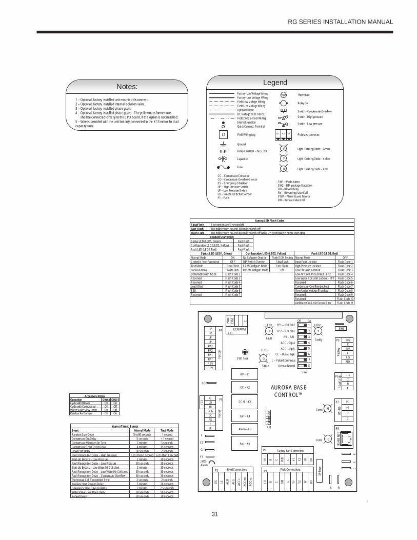
31
RG SERIES INSTALLATION MANUAL
Pa
1 – Optional, factory installed unit mounted disconnect.2 – Optional, factory installed internal isolation valve.3 – Optional, factory installed phase guard4 – Optional, factory installed phase guard. The yellow transformer wire shall be connected directly to the CPU board, if this option is not installed.5 – Wire is provided with the unit but only connected to the X13 motor for dual capacity units.
Notes:
Slow FlashFast FlashFlash Code
Status LED (LED1, Green)Configuration LED (LED2, Yellow)Faul t LED (LED3, Red)
Sta tus LED (LED1, Green)Normal ModeControl is Non-FunctionalTest ModeLockout ActiveDehumidification ModeReservedReservedLoad ShedESD
1 second on and 1 second off
Random Start DelayFast Flash
OFFON
Slow FlashFast Flash
Flash Code 2Flash Code 3
Flash Code 6
Flash Code 4Flash Code 5
Aurora LED Flash Codes
100 milliseconds on and 100 milliseconds off100 milliseconds on and 400 milliseconds off with a 2 second pause before repeating
Reserved Flash Code 7
Configuration LED (LED2, Yellow) Fault LED (LED3, Red)
Fast FlashFast Flash
No Software Overide Flash ECM SettingDIP Switch Overide Slow Flash
Normal ModeInput Fault LockoutHigh Pressure LockoutLow Pressure Lockout
Low Water Coil Limi t Lockout - FP1Low Air Coil Limi t Lockout - FP2
ReservedCondensate Overflow LockoutOver/Under Voltage ShutdownReservedReservedAir/Water Coil Limit Sensor Error
Flash Code 1OFF
Flash Code 2Flash Code 3Flash Code 4Flash Code 5
Flash Code 8
Flash Code 6Flash Code 7
Flash Code 9Flash Code 10Flash Code 11
ECM Configu re Mode Fast FlashReset Configure Mode Off
Thermistor
Relay Coi l
Switch - Condensate OverflowSwitch - High pressure
Switch - Low pressure
Polarized connector
Factory Low Voltage WiringFactory Line Vol tage WiringField Low Voltage WiringField Line Voltage Wi ringOptional BlockDC Voltage PCB Traces
Internal JunctionQuick Connect Terminal
Field Wiring Lug
Ground
Relay Con tacts – N.O., N.C.
Field Zone Sensor Wi ring
Legend
L1
Capacitor
T
123
CC – Compressor ContactorCO – Condensate Overflow SensorES – Emergency ShutdownHP – High Pressure SwitchLP – Low Pressure SwitchFD – Freeze De tection SensorF1 – Fuse
Fuse
Light Emitting Diode - GreenG
Light Emitting Diode - YellowY
Light Emitti ng Diode - RedR
SW1 – Push buttonSW2 – DIP package 8 positionRB – Blower RelayRV – Reversing Valve Coi lPGM – Phase Guard Moni torRH – Reheat Valve Coi l
Accessory Relay
Cycle with BlowerCycle with CompressorWater Valve Slow OpenOutdoor Air Damper
SW2-4 SW2-5On OnOff OffOn OffOff On
Operation
Event Normal Mode Test ModeRandom Start DelayCompressor On DelayCompressor Minimum On TimeCompressor Short Cycle DelayBlower Off DelayFaul t Recogn ition Delay – High PressureStart-Up Bypass – Low PressureFaul t Recogn ition Delay – Low PressureStart-Up Bypass – Low Water/Air Coil LimitFaul t Recogn ition Delay – Low Water/Air Coil LimitFaul t Recogn ition Delay – Condensate OverflowThermostat Call Recognition TimeAuxi liary Heat Staging DelayEmergency Heat Staging Delay
Less than 1 second
5 to 80 seconds 1 second5 seconds < 1 second
30 seconds 2 secondsLess than 1 second
2 minutes 5 seconds4 minutes 15 seconds
2 minutes
2 minutes
30 seconds30 seconds 30 seconds
30 seconds30 seconds
30 seconds30 seconds30 seconds
2 seconds 2 seconds5 minutes2 minutes
20 seconds7.5 seconds
Aurora Timing Events
Reheat Delay 30 seconds 30 secondsWater Valve Slow Open Delay 90 seconds 90 seconds
CC2
EH1
Fact
ory
Faul t
ALG
ALMLSES ACC
c
Status
AURORA BASE CONTROL™
RV – K1
CC2
CC – K2
CC Hi – K3
Fan – K4
Alarm – K5
Acc – K6
ACC
no
ACC
nc
O/BCRLO G Y1 Y2 W DH
3A-Fu
se
O/BCRLO G Y1 Y2 W DH
LOG
HICCGCCFGFR
HPHPLP
FP2FP2FP1
REVREV
CFM
PWM
ECM PWM
Fact
ory
Factory Fan Connection
R R
CC
C
RS 48
5EH2
CEH1
CCO
(+)(-)RCRS
485 E
xpFa
ctory
Com1
Com2
Config
G
G
G
YR
SW1 Test
FP1 – 15oF/30oF
JW2 - Alarm
P11
P5
P2 P1
P8
P7
P9
P6
P3
SW2
P13P4 FP2 – 15oF/30oF
RV – B/O
ACC – Dip 4
ACC – Dip 5CC – Dual/Single
L – Pulse/ContinuousReheat/Normal
Fact
ory U
se
Field ConnectionsField Connections
C
LP
FP1
F
CC
G
Y1
1
2
3
4
5
6
7
8
Off On
N/A
RS48
5 NET
LED3
LED2LED1

32
RG SERIES INSTALLATION MANUAL
Aurora ‘Base’ Control
NOTE: Refer to the Aurora Base Control Application and
Troubleshooting Guide and the Instruction Guide: Aurora
Interface and Diagnostics (AID) Tool for additional information.
Control FeaturesSoftware ABC Standard Version 3.0
Single or Dual Capacity CompressorsEither single or dual capacity compressors can be operated.
Variable Speed ECM
Blower Motor Option (If Applicable)A Variable Speed ECM blower motor can be driven directly using the onboard PWM output. Four blower speeds are available based upon the G, Y1, Y2, and W input signals to the board. The blower speeds can be changed either by the ECM manual configurations mode method or by using the Aurora AID Tool directly. All four blower speeds can be set to the same speed if desired.
5-Speed ECM Blower Motor Option (If Applicable)A 5-Speed ECM blower motor will be driven directly using the thermostat connections. Any of the G, Y1, or Y2/W signals can drive any of the 5 available pre-programmed blower speeds on the motor. All 5 Series "G" vintage units will be wired this way at the factory.
Other Control Features• Random start at power up• Anti-short cycle protection• High and low pressure cutouts• Loss of charge• Water coil freeze detection• Air coil freeze detection• Over/under voltage protection• Condensate overflow sensor• Load shed• Dehumidification (where applicable)• Emergency shutdown• Hot gas reheat operation (where applicable)• Diagnostic LED• Test mode push button switch• Two auxiliary electric heat outputs• Alarm output• Accessory output with N.O. and N.C.• Modbus communication (master)• Modbus communication (slave)
Field Selectable Options via HardwareDIP Switch (SW1) – Test/Configuration Button (See SW1 Operation Table)
Test ModeThe control is placed in the test mode by holding the push button switch SW1 for 2 - 5 seconds. In test mode most of the control timings will be shortened by a factor of sixteen (16). LED3 (green) will flash at 1 second on and 1 second off. Additionally, when entering test mode LED1 (red) will flash the last lockout one time. Test mode will automatically time out after 30 minutes. Test mode can be exited by pressing and holding the SW1 button for 2 to 5 seconds or by cycling the power. NOTE: Test mode will automatically be exited after 30 minutes.
Variable Speed ECM Configuration Mode
(If Applicable)
The control is placed in the ECM configuration mode by holding the pushbutton switch SW1 for 5 to 10 seconds, the high, low, and “G” ECM speeds can be selected by following the LED display lights. LED2 (yellow) will fast flash when entering the ECM configuration. When setting “G” speed LED3 (green) will be continuously lit, for low speed LED1 (red) will be continuously lit, and for high speed both LED3 (green) and LED1 (red) will be continuously lit. During the ECM configuration mode LED2 (yellow) will flash each of the 12 possible blower speeds 3 times. When the desired speed is flashed press SW1, LED2 will fast flash until SW1 is released. “G” speed has now been selected. Next select low speed, and high speed blower selections following the same process above. After third selection has been made, the control will exit the ECM configuration mode. Aux fan speed will remain at default or current setting and requires the AID Tool for adjustment.
Reset Configuration ModeThe control is placed in reset configuration mode by holding the push button switch SW1 for 50 to 60 seconds. This will reset all configuration settings and the EEPROM back to the factory default settings. LED3 (green) will turn off when entering reset configuration mode. Once LED3 (green) turns off, release SW1 and the control will reset.
DIP Switch (SW2) SW2-1 FP1 Selection – Low water coil temperature limit
setting for freeze detection. On = 30°F; Off = 15°F.SW2-2 FP2 Selection – On = 30°F; Off = N/ASW2-3 RV – O/B - thermostat type. Heat pump
thermostats with “O” output in cooling or “B” output in Heating can be selected. On = O; Off = B.
SW2-4 Access Relay Operation (P2)and 2-5
Access Relay Operation SW2-4 SW2-5
Cycle with Blower ON ON
Cycle with Compressor OFF OFF
Water Valve Slow Opening ON OFF
Cycle with Comm. T-stat Hum Cmd OFF ON
Controls - Aurora Base Control

33
RG SERIES INSTALLATION MANUAL
Cycle with Blower - The accessory relay will cycle with the blower output.
Cycle with Compressor - The accessory relay will cycle with the compressor output.
Water Valve Slow Opening - The accessory relay will cycle and delay both the blower and compressor output for 90 seconds.
SW2-6 CC Operation – selection of single or dual capacity compressor. On = Single Stage; Off = Dual Capacity
SW2-7 Lockout and Alarm Outputs (P2) – selection of a continuous or pulsed output for both the LO and ALM Outputs. On = Continuous; Off = Pulsed
SW2-8 Future Use
Alarm Jumper Clip SelectionFrom the factory, ALM is connected to 24 VAC via JW2. By cutting JW2, ALM becomes a dry contact connected to ALG.
Variable Speed ECM Blower SpeedsThe blower speeds can be changed either by using the ECM manual configurations mode method or by using the Aurora AID Tool directly (see Instruction Guide: Aurora Interface and Diagnostics (AID) Tool topic).
Field Selectable Options via Software(Selectable via the Aurora AID Tool)ECM Blower SpeedsAn ECM blower motor can be driven directly using the onboard PWM output. Four blower speeds are available, based upon the “G”, Y1 (low), Y2 (high), and Aux input signals to the board. The blower speeds can be changed either by the ECM manual configurations mode method (see ECM Configuration Mode topic) or by using the Aurora AID Tool directly. All four blower speeds can be set to the same speed if desired. Aux blower speed will remain at default or current setting and requires the AID Tool for adjustment.
Safety FeaturesThe following safety features are provided to protect the compressor, heat exchangers, wiring and other components from damage caused by operation outside of design conditions.
Fuse – a 3 amp automotive type plug-in fuse provides protection against short circuit or overload conditions.
Anti-Short Cycle Protection – 4 minute anti-short cycle protection for the compressor.
Random Start – 5 to 80 second random start upon power up.
Fault Retry – in the fault condition, the control will stage off the outputs and then “try again” to satisfy the thermostat Y input call. Once the thermostat input calls are satisfied, the control will continue on as if no fault occurred. If 3 consecutive faults occur without satisfying the thermostat Y input call, then the control will go to Lockout mode.
Lockout – when locked out, the blower will operate continuously in “G” speed, and PSC blower motor output will remain on. The Alarm output (ALM) and Lockout output (L) will be turned on. The fault type identification display LED1 (Red) shall flash the fault code. To reset lockout conditions with SW2-8 On, thermostat inputs “Y1”, “Y2”, and “W” must be removed for at least 3 seconds. To reset lockout conditions with SW2-8 Off, thermostat inputs “Y1”, “Y2”, “W”, and “DH” must be removed for at least 3 seconds. Lockout may also be reset by turning power off for at least 30 seconds or by enabling the emergency shutdown input for at least 3 seconds.
Lockout With Emergency Heat - if the control is locked out in the heating mode, and a Y2 or W input is received, the control will operate in the emergency heat mode while the compressor is locked out. The first emergency heat output will be energized 10 seconds after the W input is received, and the blower will shift to high speed. If the control remains locked out, and the W input is present, additional stage of emergency heat will stage on after 2 minutes. When the W input is removed, all of the emergency heat outputs will turn off, and the ECM blower will shift to “G” speed and PSC blower motor output will remain on.
High Pressure – fault is recognized when the Normally Closed High Pressure Switch, P4-9/10 opens, no matter how momentarily. The High Pressure Switch is electrically in series with the Compressor Contactor and serves as a hard-wired limit switch if an overpressure condition should occur.
Low Pressure - fault is recognized when the Normally Closed Low Pressure Switch, P4-7/8 is continuously open for 30 seconds. Closure of the LPS any time during the 30 second recognition time restarts the 30 second continuous open requirement. A continuously open LPS shall not be recognized during the 2 minute startup bypass time.
Loss of Charge – fault is recognized when the Normally Closed Low Pressure Switch, P4-7/8 is open prior to the compressor starting.
Condensate Overflow - fault is recognized when the impedance between this line and 24 VAC common or chassis ground drops below 100K ohms for 30 seconds continuously.
Freeze Detection (Coax) - set points shall be either 30°F or 15°F. When the thermistor temperature drops below the selected set point, the control shall begin counting down the 30 seconds delay. If the thermistor value rises above the selected set point, then the count should reset. The resistance value must remain below the selected set point for the entire length of the appropriate delay to be recognized as a fault. This fault will be ignored for the initial 2 minutes of the compressor run time.
Freeze Detection (Air Coil) - uses the FP2 input to protect against ice formation on the air coil. The FP2 input will operate exactly like FP1 except that the set point is 30 degrees and is not field adjustable.
Controls - Aurora Base Control cont.

34
RG SERIES INSTALLATION MANUAL
Over/Under Voltage Shutdown - An over/under voltage condition exists when the control voltage is outside the range of 18 VAC to 30 VAC. If the over/under voltage shutdown lasts for 15 minutes, the lockout and alarm relay will be energized. Over/under voltage shutdown is self-resetting in that if the voltage comes back within range of 18 VAC to 30 VAC for at least 0.5 seconds, then normal operation is restored.
Operation DescriptionPower Up - The unit will not operate until all the inputs and safety controls are checked for normal conditions. The unit has a 5 to 80 second random start delay at power up. Then the compressor has a 4 minute anti-short cycle delay after the random start delay.
Standby In standby mode, Y1, Y2, W, DH, and G are not active. Input O may be active. The blower and compressor will be off.
Heating OperationSingle Compressor Heating, 2nd Stage (Y1, Y2) The compressor will be staged to full capacity 20 seconds after Y2 input is received. The ECM blower will shift to high speed seconds after the Y2 input is received.
Dual Compressor Heating, 2nd Stage (Y1, Y2) In dual compressor operation, two ABC boards used in 24 VAC operation, there will be a Y2 call to the Y1 input on the second ABC. The compressor will stage to full capacity 30 seconds after Y1 input is received to the second board.
Single Compressor Heating, 3rd Stage (Y1, Y2, W) The hot water pump is de-energized and the first stage of electric heat is energized 10 seconds after the W command is received. If the demand continues the second stage of electric heat will be energized after 5 minutes.
Dual Compressor Heating, 3rd Stage (Y1, Y2, W) - The first stage of electric heat is energized 10 seconds after the W command is received. If the demand continues the second stage of electric heat will be energized after 5 minutes
Emergency Heat (W) - The blower will be started on “G” speed, 10 seconds later the first stage of electric heat will be turned on. 5 seconds after the first stage of electric heat is energized the blower will shift to Aux speed. If the emergency heat demand is not satisfied after 2 minutes the second electric heat stage will be energized.
Blower (G) - The blower will start immediately upon receiving a thermostat G command. If there are no other commands from the thermostat the ECM will run on “G” speed until the G command is removed. Regardless of blower input (G) from the thermostat, the blower will remain on for 30 seconds at the end of each heating cycle.
Cooling OperationIn all cooling operations, the reversing valve directly tracks the O input. Thus, anytime the O input is present, the reversing valve will be energized.
Single Compressor Cooling, 2nd Stage (Y1, Y2, 0) The compressor will be staged to full capacity 20 seconds after Y2 input was received. The ECM blower will shift to high speed 15 seconds after the Y2 input was received.
Dual Compressor Cooling, 2nd Stage (Y1, Y2, O) In dual compressor operation, two ABC boards used in 24 VAC operation, there will be a Y2 call to the Y1 input on the second ABC. The compressor will stage to full capacity 30 seconds after Y1 input is received to the second board.
Blower (G) - The blower will start immediately upon receiving a thermostat G command. If there are no other commands from the thermostat the ECM will run on “G” speed until the G command is removed. Regardless of blower input (G) from the thermostat, the blower will remain on for 30 seconds at the end of each heating, cooling, and emergency heat cycle.
Dehumidification (Y1, O, DH or Y1, Y2, O, DH) - When a DH command is received from the thermostat during a compressor call for cooling the ECM blower speed will be reduced by 15% to increase dehumidification.
Emergency Shutdown - Four (4) seconds after a valid ES input, P2-7 is present, all control outputs will be turned off and remain off until the emergency shutdown input is no longer present. The first time that the compressor is started after the control exits the emergency shutdown mode, there will be an anti-short cycle delay followed by a random start delay. Input must be tied to common to activate.
Continuous Blower Operation - The blower output will be energized any time the control has a G input present, unless the control has an emergency shutdown input present. The blower output will be turned off when G input is removed.
Load Shed - The LS input disables all outputs with the exception of the blower output. When the LS input has been cleared, the anti-short cycle timer and random start timer will be initiated. Input must be tied to common to activate.
Controls - Aurora Base Control cont.

35
RG SERIES INSTALLATION MANUAL
CC2
EH1
Fact
ory
Faul t
ALG
ALMLSES ACC
cStatus
AURORA BASE CONTROL™
RV – K1
CC2
CC – K2
CC Hi – K3
Fan – K4
Alarm – K5
Acc – K6
ACC
no
ACC
nc
O/BCRLO G Y1 Y2 W DH
3A-Fu
se
O/BCRLO G Y1 Y2 W DH
LOG
HICCGCCFGFR
HPHPLP
FP2FP2FP1
REVREV
CFM
PWM
ECM PWM
Fact
ory
Factory Fan Connection
R RC
CC
RS 48
5
EH2C
EH1C
CO
(+)(-)RCRS
485 E
xpFa
ctory
Com1
Com2
Config
G
G
G
YR
SW1 Test
FP1 – 15oF/30oF
JW2 - Alarm
P11
P5
P2 P1
P8
P7
P9
P6
P3
SW2
P13P4 FP2 – 15oF/30oF
RV – B/OACC – Dip 4
ACC – Dip 5CC – Dual/Single
L – Pulse/ContinuousReheat/Normal
Fact
ory U
se
Field ConnectionsField Connections
C
LP
FP1
F
CC
G
Y1
1
2
3
4
5
6
7
8
Off On
N/A
RS48
5 NET
LED3
LED2LED1
Aurora Interface and Diagnostics (AID) ToolThe Aurora Interface and Diagnostics (AID) Tool is a device that is a member of the Aurora network. The AID Tool is used to troubleshoot equipment which uses the Aurora control via Modbus RTU communication. The AID Tool provides diagnostics, fault management, ECM setup, and system configuration capabilities to the Aurora family of controls. An AID Tool is recommended, although not required, for ECM airflow settings. The AID Tool simply plugs into the exterior of the cabinet in the AID Tool port.
ABC Control Board Layout
Aurora ‘Base’ Control LED DisplaysThese three LEDs display the status, configuration, and fault codes for the control. These can also be read in plain English via the Aurora AID Tool.
Status LED (LED3, Green)
Description of Operation Fault LED, Green
Normal Mode ON
Control is Non-functional OFF
Test Mode Slow Flash
Lockout Active Fast Flash
Dehumidification Mode Flash Code 2
(Future Use) Flash Code 3
(Future Use) Flash Code 4
Load Shed Flash Code 5
ESD Flash Code 6
(Future Use) Flash Code 7
Configuration LED (LED2, Yellow)
Description of Operation Configuration LED, Yellow
No Software Overwritten Flashing ECM Setting
DIP Switch was Overwritten Slow Flash
ECM Configuration Mode Fast Flash
Fault LED (LED1, Red)
Red Fault LEDLED Flash
Code*Lockout
Reset/Remove
AB
C B
asi
c F
au
lts
Normal - No Faults OFF –
Fault - Input 1 No Auto
Fault - High Pressure 2 Yes Hard or Soft
Fault - Low Pressure 3 Yes Hard or Soft
Fault - Freeze Detection FP2 4 Yes Hard or Soft
Fault - Freeze Detection FP1 5 Yes Hard or Soft
Fault - Condensate Overflow 7 Yes Hard or Soft
Fault - Over/Under Voltage 8 No Auto
Fault - FP1 & FP2 Sensor Error 11 Yes Hard or Soft
NOTE: All codes >11 use long flash for tens digit and short flash for the ones digit. 20, 30, 40, 50, etc. are skipped.
Controls - Aurora Base Control cont.

36
RG SERIES INSTALLATION MANUAL
Before Powering Unit, Check The Following:NOTE: Remove and discard the compressor shipping bolts. The bolts can then be discarded.• High voltage is correct and matches nameplate.• Fuses, breakers and wire size correct.• Low voltage wiring complete.• Piping completed and water system cleaned and flushed.• Air is purged from closed loop system.• Isolation valves are open, water control valves or loop pumps wired.• Condensate line open and correctly pitched.• Transformer switched to 208V if applicable.• Dip switches are set correctly.• Blower rotates freely – foam shipping support has been removed.• Blower speed correct.• Air filter/cleaner is clean and in position.• Service/access panels are in place.• Return air temperature is between 50-80°F heating and 60-95°F cooling.• Check air coil cleanliness to insure optimum performance. Clean as needed according to maintenance guidelines. To obtain maximum performance the air coil should be cleaned before startup. A 10-percent solution of dishwasher detergent and water is recommended for both sides of coil, a thorough water rinse should follow.
Startup StepsNOTE: Complete the Equipment Start-Up/Commissioning Check Sheet during this procedure. Refer to thermostat operating instructions and complete the startup procedure.1. Initiate a control signal to energize the blower motor. Check blower operation. 2. Initiate a control signal to place the unit in the cooling mode. Cooling setpoint must be set below room temperature. 3. Cooling will energize after a time delay. Check for correct rotation of scroll compressors in 3 phase applications. Incorrect rotation will cause low refrigerant pressures and possibly unusual noise. Switch any two power leads at the compressor or contactor to reverse rotation. 4. Be sure that the compressor and water control valve or loop pump(s) are activated. 5. Verify that the water flow rate is correct by measuring the pressure drop through the heat exchanger using the P/T plugs and comparing to the pressure drop table. 6. Check the temperature of both the supply and discharge water (Refer to Operating Parameters tables). 7. Check for an air temperature drop of 15°F to 25°F across the air coil, depending on the blower speed and entering water temperature.8. Decrease the cooling set point several degrees and verify high-speed blower operation (Variable speed ECM only). 9. Adjust the cooling setpoint above the room temperature and verify that the compressor and water valve or loop pumps deactivate.10. Initiate a control signal to place the unit in the heating mode. Heating set point must be set above room temperature. 11. Heating will energize after a time delay. 12. Check the temperature of both the supply and discharge water (Refer to Unit Operating Parameters tables). 13. Check for an air temperature rise of 20°F to 35°F across the air coil, depending on the blower speed and entering water temperature.14. If auxiliary electric heaters are installed, increase the heating setpoint until the electric heat banks are sequenced on. All stages of the auxiliary heater should be sequenced on when the thermostat is in the Emergency Heat mode. Check amperage of each element.15. Adjust the heating setpoint below room temperature and verify that the compressor and water valve or loop pumps deactivate. 16. During all testing, check for excessive vibration, noise or water leaks. Correct or repair as required. 17. Set system to desired normal operating mode and set temperature to maintain desired comfort level. 18. Instruct the owner/operator in the proper operation of the thermostat and system maintenance.
NOTE: Be certain to fill out and forward all warranty registration papers.
Unit Startup

37
RG SERIES INSTALLATION MANUAL
Operating ParametersEntering
Water Temp°F
Water Flow gpm/Ton
Cooling -- No Hot Water Generation
Suction PressurePSIG
Discharge PressurePSIG Superheat Subcooling Water Temp Rise
°FAir Temp Drop
°F DB
301.5 100-115 170-190 17 - 26 10 - 14 18 - 22 18 - 22
3.0 95-110 150-170 20 - 29 7 - 11 8 - 10 18 - 22
501.5 133 - 148 205 - 225 17 - 26 10 - 14 18 - 22 18 - 22
3.0 129 - 144 185 - 205 20 - 29 7 - 11 8 - 10 18 - 22
701.5 139 - 154 280 - 300 8 - 11 8 -12 18 - 22 18 - 22
3.0 137 - 152 250 - 270 9 - 12 7 - 11 8 - 10 18 - 22
901.5 143 - 158 360 - 380 8 - 11 9 - 13 18 - 22 16 - 20
3.0 141 - 156 330 - 350 9 - 12 8 - 12 8 - 10 16 - 20
1102.3 143 - 158 360 - 380 8 - 11 9 - 13 18 - 22 16 - 20
3.0 141 - 156 440-460 9 - 12 8 - 12 8 - 10 16 - 20
Entering Water Temp
°F
Water Flow gpm/Ton
Heating -- No Hot Water Generation
Suction Pressure PSIG
Discharge Pres-sure PSIG Superheat Subcooling Water Temp Drop
°FAir Temp Rise °F
DB
301.5 73 - 79 279 - 304 7 - 13 2 - 6 7 -10 18 - 24
3.0 79 - 85 285 - 310 8 - 14 2 - 6 3 - 6 20 - 26
501.5 103 - 109 308 - 333 8 - 12 4 - 8 8 - 11 20 - 26
3.0 110 - 116 315 - 340 9 - 13 4 - 8 4 - 7 22 - 28
701.5 140 - 146 330 - 365 10 - 14 7 - 11 11 - 14 26 - 32
3.0 146 - 153 340 - 375 10 - 14 7 - 11 7 - 10 28 - 34
901.5 170-177 425-460 14-18 12-16 8-11 42-50
3.0 174-181 435-470 14-18 12-16 8-11 42-50
1102.3
3.0
11/10/09NOTES: Cooling performance based on entering air temperatures of 80°F DB, 67°F WB. Heating performance based on entering air temperature of 70°F DB.
Operating LimitsOperating Limits Cooling Heating
(°F) (°C) (°F) (°C)Air Limits Min. Ambient Air 45 7.2 45 7.2 Rated Ambient Air 80 26.7 70 21.1 Max. Ambient Air 100 37.8 85 29.4 Min. Entering Air 50 10.0 40 4.4 Rated Entering Air db/wb 80.6/66.2 27/19 68 20.0 Max. Entering Air db/wb 110/83 43/28.3 80 26.7Water Limits Min. Entering Water 30 -1.1 20 -6.7 Normal Entering Water 50-110 10-43.3 30-70 -1.1 Max. Entering Water 120 48.9 90 32.2
NOTE: Minimum/maximum limits are only for start-up conditions, and are meant for bringing the space up to occupancy temperature. Units are not designed to operate at the minimum/maximum conditions on a regular basis. The operating limits are dependant upon three primary factors: 1) water temperature, 2) return air temperature, and 3) ambient temperature. When any of the factors are at the minimum or maximum levels, the other two factors must be at the normal level for proper and reliable unit operation.

38
RG SERIES INSTALLATION MANUAL
Pressure Drop
Model gpmPressure Drop (psi)
30°F 50°F 70°F 90°F 110°F
009
1.5 2.0 1.7 1.4 1.3 1.02.0 3.8 3.2 2.8 2.3 1.83.0 7.2 6.0 5.1 4.5 4.04.0 12.0 10.0 9.0 7.5 6.0
012
1.5 1.1 1.0 0.9 0.8 0.72.5 2.5 2.3 2.1 1.8 1.53.5 3.9 3.6 3.2 2.7 2.34.5 5.3 4.9 4.5 3.8 3.5
015
2.0 0.6 0.5 0.5 0.4 0.43.0 1.1 1.0 0.9 0.8 0.64.0 1.9 1.8 1.6 1.5 1.35.0 3.3 3.2 3.0 2.9 2.7
018
3.0 1.1 1.0 0.9 0.8 0.64.0 1.9 1.8 1.6 1.5 1.35.0 3.3 3.2 3.0 2.9 2.76.0 4.5 4.4 4.3 4.1 4.0
023
3.0 1.1 1.0 0.9 0.8 0.64.5 2.4 2.2 2.1 2.0 1.96.0 4.5 4.4 4.3 4.1 4.08.0 6.7 6.6 6.5 6.3 6.2
024
3.0 1.1 1.0 0.9 0.8 0.64.5 2.4 2.2 2.1 2.0 1.96.0 4.5 4.4 4.3 4.1 4.08.0 6.7 6.6 6.5 6.3 6.2
030
4.0 0.9 0.8 0.7 0.6 0.56.0 1.9 1.8 1.7 1.6 1.58.0 3.7 3.6 3.5 3.4 3.3
10.0 4.8 4.7 4.6 4.5 4.4
036
5.0 1.4 1.1 0.9 0.7 0.57.0 2.5 2.3 2.1 1.8 1.69.0 6.0 5.8 5.5 5.3 5.1
12.0 6.6 6.4 6.2 6.0 5.7
041
5.0 1.5 1.2 0.9 0.5 0.48.0 3.4 3.1 2.8 2.5 2.111.0 7.9 7.5 7.2 6.9 6.614.0 9.1 8.8 8.5 8.2 7.9
042
5.0 1.5 1.2 0.9 0.5 0.48.0 3.4 3.1 2.8 2.5 2.111.0 7.9 7.5 7.2 6.9 6.614.0 9.1 8.8 8.5 8.2 7.9
048
6.0 2.0 1.7 1.3 1.0 0.69.0 4.2 3.8 3.5 3.1 2.7
12.0 6.7 6.3 5.9 5.6 5.216.0 11.5 11.2 10.8 10.5 10.1
060
9.0 3.6 3.3 3.0 2.7 2.312.0 6.1 5.8 5.5 5.2 4.815.0 9.6 9.2 8.9 8.6 8.320.0 15.5 15.2 14.9 14.5 14.2
070
12.0 4.1 3.6 3.2 2.8 2.315.0 5.9 5.0 4.6 4.1 3.718.0 8.8 8.4 7.9 7.5 7.124.0 12.9 12.0 11.5 11.1 10.7
7/6/10
Valve gpm CvPressure Drop (psi)
1/2 in.
1.5 9.6 0.022.0 9.7 0.043.0 9.9 0.094.0 10.1 0.16
1/2 in.
1.5 9.6 0.022.5 9.8 0.063.5 10.0 0.124.5 10.2 0.19
1/2 in.
2.0 9.7 0.043.0 9.9 0.094.0 10.1 0.165.0 10.4 0.23
1/2 in.
3.0 9.9 0.094.0 10.1 0.165.0 10.4 0.236.0 10.6 0.32
3/4 in.
3.0 9.9 0.094.5 10.2 0.196.0 10.6 0.328.0 11.0 0.53
3/4 in.
3.0 9.9 0.094.5 10.2 0.196.0 10.6 0.328.0 11.0 0.53
3/4 in.
4.0 10.1 0.166.0 10.6 0.328.0 11.0 0.53
10.0 11.5 0.76
3/4 in.
5.0 10.4 0.237.0 10.8 0.429.0 11.2 0.64
12.0 11.9 1.02
3/4 in.
5.0 10.4 0.238.0 11.0 0.5311.0 11.7 0.8914.0 12.3 1.29
1 in.
5.0 15.9 0.108.0 16.6 0.2311.0 17.2 0.4114.0 17.9 0.61
1 in.
6.0 16.1 0.149.0 16.8 0.29
12.0 17.4 0.4716.0 18.3 0.76
1 in.
9.0 16.8 0.2912.0 17.4 0.4715.0 18.1 0.6920.0 19.2 1.09
1 in.
12.0 17.4 0.4715.0 18.1 0.6918.0 18.7 0.9224.0 20.1 1.43
11/10/09

39
RG SERIES INSTALLATION MANUAL
Symptom Head Pressure
Suction Pressure
CompressorAmp Draw Superheat Subcooling Air Temp.
DifferentialWater Temp. Differential
Under Charged System (Possible Leak) Low Low Low High Low Low LowOver Charged System High High High Normal High Normal/Low NormalLow Air Flow Heating High High High High/Normal Low High LowLow Air Flow Cooling Low Low Low Low/Normal High High LowLow Water Flow Heating Low/Normal Low/Normal Low Low High Low HighLow Water Flow Cooling High High High High Low Low HighHigh Air Flow Heating Low Low Low Low High Low LowHigh Air Flow Cooling Low High Normal High Low Low NormalHigh Water Flow Heating Normal Low Normal High Normal Normal LowHigh Water Flow Cooling Low Low Low Low High Normal LowLow Indoor Air Temperature Heating Low Low Low Normal High Normal Normal/HighLow Indoor Air Temperature Cooling Low Low Low Normal/Low High Low LowHigh Indoor Air Temperature Heating High High High Normal/High Normal/Low Low NormalHigh Indoor Air Temperature Cooling High High High High Low Low HighRestricted TXV (Check Service Advisory) High Low Normal/Low High High Low LowInsufficient Compressor (Possible Bad Valves) Low High Low High Normal/High Low LowTXV - Bulb Loss of Charge Low Low Low High High Low LowScaled Coaxial Heat Exchanger Heating Low Low Low Normal/Low High Low LowScaled Coaxial Heat Exchanger Cooling High High High Normal/Low Low Low LowRestricted Filter Drier Check temperature difference (delta T) across filter drier.
7/6/10
Refrigerant Circuit Guideline
Reference CalculationsHeating Calculations: Cooling Calculations:
LWT = EWT +
LAT(DB) = EAT(DB) -
LC = TC - SC
S/T =
HRgpm x 500
SCcfm x 1.08
SCTC
HEgpm x 500
LWT = EWT -
LAT = EAT +
TH = HC + HWC
HCcfm x 1.08
LegendABBREVIATIONS AND DEFINITIONS:
cfm = airflow, cubic feet/minuteEWT = entering water temperature, Fahrenheitgpm = water flow in gallons/minuteWPD = water pressure drop, PSI and feet of waterEAT = entering air temperature, Fahrenheit (dry bulb/wet bulb)HC = air heating capacity, MBtu/hTC = total cooling capacity, MBtu/hSC = sensible cooling capacity, MBtu/hKW = total power unit input, kilowattsHR = total heat of rejection, MBtu/h
HE = total heat of extraction, MBtu/hHWC = hot water generator capacity, MBtu/hEER = Energy Efficient Ratio = BTU output/Watt inputCOP = Coefficient of Performance = BTU output/BTU inputLWT = leaving water temperature, °FLAT = leaving air temperature, °FTH = total heating capacity, MBtu/hLC = latent cooling capacity, MBtu/hS/T = sensible to total cooling ratio

40
RG SERIES INSTALLATION MANUAL
Compressor and Thermistor ResistanceCompressor Resistance Chart
Model 208-230/60/1 265/60/1 208-230/60/3 460/60/3 575/60/4Run Start Run Start009 3.65 - 4.19 3.75 - 4.31 3.73 - 4.27 4.45 - 5.13 n/a n/a n/a012 3.35 - 3.85 2.80 - 3.22 3.73 - 4.27 4.45 - 5.13 n/a n/a n/a015 2.74 - 3.16 2.60 - 3.00 3.03 - 3.49 2.39 - 2.75 n/a n/a n/a018 2.24 - 2.58 2.84 - 3.26 3.03 - 3.49 2.39 - 2.75 n/a n/a n/a
023-024 1.14 - 1.32 1.37 - 1.57 1.38 - 1.58 2.02 - 2.32 1.45 - 1.67 8.04 - 9.24 n/a030 0.95 - 1.09 1.81 - 2.09 1.24 - 1.42 2.42 - 2.78 1.77 - 2.04 7.57 - 8.71 n/a036 0.62 - 0.72 1.46 - 1.65 1.13 - 1.31 1.07 - 1.23 0.83 - 0.91 4.43 - 4.90 n/a
041-042 0.49 - 1.03 1.29 - 1.49 n/a 0.81 - 1.05 4.33 - 4.99 5.11 - 5.64048 0.51 - 0.58 1.36 - 1.57 n/a 0.91 - 1.05 3.60 - 4.14 4.16 - 4.78060 0.29 - 0.34 0.76 - 0.87 n/a 0.56 - 0.64 2.17 - 2.49 3.78 - 4.34070 0.26 - 0.29 0.76 - 0.87 n/a 0.56 - 0.64 2.17 - 2.49 3.78 - 4.35
7/6/10
Thermistor Resistance ChartThermistor
Temperature (°F)Microprocessor
Resistance (Ohms)5 75757-70117
14 57392-5323423 43865-4077132 33809-3148741 26269-2451350 20570-1923059 16226-1519668 12889-1209377 10310-968886 8300-781295 6723-6337
104 5480-5172113 4490-4246122 3700-3504131 3067-2907140 2554-2424149 2149-2019
7/8/15

41
RG SERIES INSTALLATION MANUAL
Heat of Extraction/Rejection DataModel gpm Heat Of Extraction (HE) Heat of Rejection (HR)
30°F 50°F 70°F 90°F 30°F 50°F 70°F 90°F 110°F
0091.5 5.2 7.1 9.9 13.1 12.2 11.32.0 3.9 5.4 7.4 10.1 13.0 13.1 12.2 11.3 10.63.0 4.6 5.8 7.9 10.3 13.0 13.0 12.3 11.3 10.6
0121.5 7.4 9.6 12.5 16.9 16.5 15.82.5 5.9 7.7 10.1 12.7 17.3 16.9 16.4 15.9 16.03.5 6.1 8.1 10.6 12.9 17.4 16.9 16.4 16.0 16.1
0152.0 9.4 12.0 15.6 19.4 18.2 17.13.0 7.4 9.7 12.5 15.9 16.9 19.6 18.4 17.2 16.74.0 7.6 10.0 13.0 16.1 17.0 19.8 18.5 17.3 16.8
0183.0 11.4 13.9 19.1 23.0 21.6 20.54.0 10.1 12.2 14.8 19.5 21.1 23.3 21.7 20.5 20.15.0 10.4 13.1 15.8 19.8 21.2 23.6 21.9 20.7 20.1
0233.0 14.7 18.8 24.1 31.1 30.7 29.64.5 11.9 15.4 19.6 24.5 30.1 31.1 30.6 29.6 29.26.0 12.2 16.0 20.4 24.9 30.2 31.1 30.6 29.8 29.3
0243.0 15.6 19.8 25.4 32.2 31.8 30.54.5 12.7 16.3 20.6 25.8 31.2 32.2 31.7 30.6 29.56.0 13.0 16.9 21.5 26.2 31.4 32.2 31.6 30.8 29.7
0304.0 18.9 25.9 32.9 35.2 35.4 37.06.0 14.5 19.9 27.0 33.4 35.1 37.2 37.6 37.6 34.78.0 15.2 20.9 28.0 34.0 35.2 39.1 39.7 37.9 35.0
0365.0 24.6 33.0 41.7 47.4 45.3 44.17.0 19.0 25.7 34.3 42.4 41.5 47.7 45.8 44.2 42.49.0 19.6 26.8 35.5 43.1 41.7 48.1 46.3 44.6 42.7
0415.0 23.7 31.6 41.0 53.1 52.7 51.68.0 18.9 25.1 32.9 41.7 48.4 53.3 53.5 51.7 48.511.0 19.7 26.5 34.3 42.4 48.6 53.6 54.2 52.2 48.9
0425.0 25.5 33.8 43.8 55.0 54.5 53.48.0 20.4 27.0 35.2 44.5 50.2 55.3 55.3 53.5 50.011.0 21.2 28.4 36.7 45.2 50.4 55.5 56.1 54.0 50.4
0486.0 31.0 43.0 52.9 64.6 65.8 62.59.0 24.0 33.3 45.7 53.7 58.3 65.2 65.9 62.7 59.9
12.0 24.4 35.6 48.4 54.6 58.5 65.8 66.0 63.2 60.4
0609.0 40.3 54.4 66.8 79.9 79.4 75.0
12.0 30.2 41.7 56.9 67.8 82.1 80.6 79.9 75.2 71.615.0 32.5 43.1 59.3 68.9 82.5 81.3 80.4 75.9 72.1
07012.0 44.9 61.7 78.0 87.0 84.0 80.415.0 35.2 47.4 63.1 79.2 84.3 88.7 85.2 80.4 78.018.0 36.4 49.8 64.5 80.5 84.6 90.5 86.4 81.1 78.5
7/6/10

42
RG SERIES INSTALLATION MANUAL
Should a major problem develop, refer to the following information for possible causes and corrective steps.If compressor won’t run:1. The fuse may be open or the circuit breaker is tripped. Check electrical circuits and motor windings for shorts or grounds. Investigate
for possible overloading. Replace fuse or reset circuit breakers after fault is corrected.2. Supply voltage may be too low. Check it with a volt meter.3. Control system may be faulty. Check control for correct wiring of thermostat or aquastat and check the 24 volt transformer for
proper voltage. 4. Wires may be loose or broken. Replace or tighten.5. The low pressure switch may have tripped due to one or more of the following: a) Heating 1) Plugged heat exchanger on source side 2) Water flow source side - (Low) 3) Water too cold source side 4) Low refrigerant b) Cooling 1) Plugged heat exchanger on load side 2) Water flow load side - (Low) 3) Water too cold load side 4) Low refrigerant6. The high pressure switch may have tripped due to one or more of the following: a) Heating 1) Plugged heat exchanger on load side 2) Low water flow load side 3) Water too warm load side b) Cooling 1) Plugged heat exchanger on source side 2) Low water flow on source side 3) Water too warm source side7. The compressor overload protection may be open.8. The internal winding of the compressor motor may be grounded to the compressor shell. If so, replace the compressor.9. The compressor winding may be open or shorted. Disconnect power. Check continuity with ohm meter. If the winding is open, replace
the compressor.
If sufficient cooling or heating is not obtained:1. Check control for improper location or setting.2. Check for restriction in water flow.3. Check refrigerant subcooling and superheat for proper refrigerant charge and expansion valve operation.4. The reversing valve may be defective and creating a bypass of refrigerant. If the unit will not heat, check the reversing valve coil.
If the unit operation is noisy:1. Check compressor for loosened mounting bolts. Make sure compressor is floating free on its isolator mounts. Check for tubing contact
with the compressor or other surfaces. Readjust it by bending slightly. 2. Check screws on all panels.3. Check for chattering or humming in the contactor or relays due to low voltage or a defective holding coil. Replace the component.4. Check for proper installation of vibration absorbing material under the unit.5. Check for abnormally high discharge pressures.6. Compressor rotation incorrect
Refrigerant Systems To maintain sealed circuit integrity, do not install service gauges unless unit operation appears abnormal. Compare the change in temperature on the air side as well as the water side to the Operating Parameters tables. If the unit’s performance is not within the ranges listed, and the airflow and water flow are known to be correct, gauges should then be installed and superheat and subcooling numbers calculated. If superheat and subcooling are outside recommended ranges, an adjustment to the refrigerant charge may be necessary.
NOTE: Refrigerant tests must be made with hot water generator turned “OFF”. Verify that air and water flow rates are at proper levels before servicing the refrigerant circuit.
Troubleshooting

43
RG SERIES INSTALLATION MANUAL
Check One Start up/Check-out for new installation ❑ Troubleshooting Problem:___________________________________❑
1. FLOW RATE IN GPM (COAXIAL HEAT EXCHANGER)
Water In Pressure: a.______ PSIWater Out Pressure: b.______ PSIPressure Drop = a - b c.______ PSIConvert Pressure Drop to Flow Rate (refer to Pressure Drop table) d.______ GPM
2. TEMPERATURE RISE OR DROP ACROSS COAXIAL HEAT EXCHANGER
COOLING HEATINGWater In Temperature: e.______ °F e.______ °FWater Out Temperature: f. ______ °F f. ______ °FTemperature Difference: g.______ °F g.______ °F
3. TEMPERATURE RISE OR DROP ACROSS AIR COIL
COOLING HEATINGAir In Temperature: h.______ °F h.______ °FAir Out Temperature: i. ______ °F i. ______ °FTemperature Difference: j. ______ °F j. ______ °F
4. HEAT OF REJECTION (HR) / HEAT OF EXTRACTION (HE) CALCULATION
HR or HE = Flow Rate x Temperature Difference x Brine Factor* d. (above) x g. (above) x 485 for Methanol or Environol, 500 for water*Heat of Extraction (Heating Mode) = btu/hrHeat of Rejection (Cooling Mode) = btu/hrCompare results to Capacity Data Tables
Note: Steps 5 through 8 need only be completed if a problem is suspected
5. WATTSCOOLING HEATING
Volts: m._____ VOLTS m.______ VOLTSTotal Amps (Comp. + Fan): n. _____ AMPS n. ______ AMPSWatts = m. x n. x 0.85 o. _____ WATTS o. ______ WATTS
6. CAPACITYCooling Capacity = HR. - (o. x 3.413) p. _____ btu/hrHeating Capacity= HE. + (o. x 3.413) p. _____ btu/hr
7. EFFICIENCYCooling EER = p. / o. q. _____ EERHeating COP = p. / (o. x 3.413) q. _____ COP
8. SUPERHEAT (S.H.) / SUBCOOLING (S.C.) COOLING HEATING
Suction Pressure: r. ______ PSI r. ______ PSISuction Saturation Temperature: s. ______ °F s. ______ °FSuction Line Temperature: t. ______ °F t. ______ °FSuperheat = t. - s. u. _____ °F u. ______ °F
Head Pressure: v. ______ PSI v. ______ PSIHigh Pressure Saturation Temp.: w. _____ °F w. _____ °FLiquid Line Temperature*: x. ______ °F x. ______ °FSubcooling = w. - x. y. ______ °F y. ______ °F
* Note: Liquid line is between the coaxial heat exchanger and the expansion valve in the cooling mode; between the air coil and the expansion valve in the heating mode.
Company Name: _________________________________Technician Name: ________________________________Model No: ______________________________________Owner’s Name: __________________________________Installation Address: ______________________________
Company Phone No: ______________________________Date: __________________________________________Serial No:_______________________________________Open or Closed Loop: _____________________________Installation Date: _________________________________
Startup and Troubleshooting Form

44
RG SERIES INSTALLATION MANUAL
COOLING CYCLE ANALYSIS
Hot WaterGenerator
-
EXPANSIONVALVE
°F AIRCOIL
°F
°F°F
°FPSI PSI
BRINE IN BRINE OUT
COMPRESSOR
DISCHARGE
SUCTION
Subcooling
Superheat
REVERSINGVALVE
PSI
°F
SAT °F=
PSI = SAT F
F°FLIQUID LINE
Water to Water Application
°
°
°F
COAXLOAD
COAXSOURCE
°F°F
PSI PSIBRINE IN BRINE OUT
Heat of Extraction/Rejection = GPM x 500 (485 for water/antifreeze) x ∆TNote: DO NOT hook up pressure gauges unless there appears to be a performance problem.
Line Voltage:
Loop: OpenUnit Amp Draw:
Closed
COAXSOURCE
COAXLOAD
HEATING CYCLE ANALYSIS
-
EXPANSIONVALVE
°F AIRCOIL
°F
°F°F
°FPSI PSI
BRINE IN BRINE OUT
COMPRESSOR
DISCHARGE
SUCTION
Subcooling
Superheat
REVERSINGVALVE
PSI
°F
SAT °F=
PSI = SAT F
FFLIQUID LINE
Water to Water Application
°
°
°
°F
°F°F
PSI PSIBRINE IN BRINE OUT
Line Voltage:
Loop: OpenUnit Amp Draw:
Closed
DEALER:
PHONE #: DATE:
PROBLEM:
MODEL #:
SERIAL #: Startup/Troubleshooting Form
Hot WaterGenerator
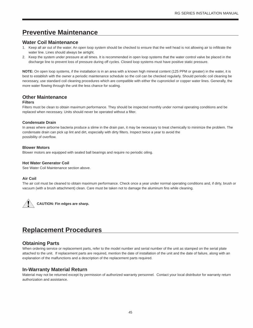
45
RG SERIES INSTALLATION MANUAL
Water Coil Maintenance1. Keep all air out of the water. An open loop system should be checked to ensure that the well head is not allowing air to infiltrate the
water line. Lines should always be airtight. 2. Keep the system under pressure at all times. It is recommended in open loop systems that the water control valve be placed in the
discharge line to prevent loss of pressure during off cycles. Closed loop systems must have positive static pressure.
NOTE: On open loop systems, if the installation is in an area with a known high mineral content (125 PPM or greater) in the water, it is best to establish with the owner a periodic maintenance schedule so the coil can be checked regularly. Should periodic coil cleaning be necessary, use standard coil cleaning procedures which are compatible with either the cupronickel or copper water lines. Generally, the more water flowing through the unit the less chance for scaling.
Other MaintenanceFilters Filters must be clean to obtain maximum performance. They should be inspected monthly under normal operating conditions and be replaced when necessary. Units should never be operated without a filter.
Condensate DrainIn areas where airborne bacteria produce a slime in the drain pan, it may be necessary to treat chemically to minimize the problem. The condensate drain can pick up lint and dirt, especially with dirty filters. Inspect twice a year to avoid the possibility of overflow.
Blower MotorsBlower motors are equipped with sealed ball bearings and require no periodic oiling.
Hot Water Generator CoilSee Water Coil Maintenance section above.
Air CoilThe air coil must be cleaned to obtain maximum performance. Check once a year under normal operating conditions and, if dirty, brush or vacuum (with a brush attachment) clean. Care must be taken not to damage the aluminum fins while cleaning.
Replacement Procedures
Obtaining PartsWhen ordering service or replacement parts, refer to the model number and serial number of the unit as stamped on the serial plate attached to the unit. If replacement parts are required, mention the date of installation of the unit and the date of failure, along with an explanation of the malfunctions and a description of the replacement parts required.
In-Warranty Material ReturnMaterial may not be returned except by permission of authorized warranty personnel. Contact your local distributor for warranty return authorization and assistance.
CAUTION: Fin edges are sharp.
Preventive Maintenance

46
RG SERIES INSTALLATION MANUAL
Service Parts
Part DescriptionSingle Speed Horizontal Units
009 012 015 018 023 024 030 036 042 048 060 070
Co
mp
ress
or
Compressor 208-230/60/1 34P590-01 34P591-01 34P592-01 34P593-01 34P624-01 34P624-01 34P583-01 34P625-01 34P621-01 34P623-01 34P613-01 34P616-01
265/60/1 34P590-02 34P591-02 34P592-02 34P593-02 34P624-02 34P624-02 34P583-02 34P627-02 Not Available
230/60/3 Not Available 34P624-03 34P624-03 34P583-03 34P625-03 34P621-03 34P623-03 34P613-03 34P616-03
460/60/3 Not Available 34P624-04 34P624-04 34P583-04 34P625-04 34P621-04 34P623-04 34P613-04 34P616-04
575/60/3 Not Available 34P621-05 34P623-05 34P613-05 34P616-05
Run Capacitor 208-230/60/1 16P002D17 16P002D18 16P002D19 16P002D20 16P002D21 16P002D35 16P002D23 16P002D25 16P002D24
Run Capacitor 265/60/1 16P002D27 16P002D30 16P002D20 16P002D23 Not Available
Sound Jacket 92P504A01 92P504A05 92P519-02
EC
M M
oto
r &
Blo
we
r
ECM Motor 208-230/60/1 Not Available 14S551-01 14S552-01 14S553-01
ECM Motor 265/60/1 Not Available 14S551-02 Not Available
ECM Motor 230/60/3 Not Available 14S551-01 14S552-01 14S553-01
ECM Motor 460/60/3 Not Available 14S551-02 14S552-02 14S553-02
ECM Blower Housing Not Available 53P512B01 53P515B01
PS
C M
oto
r &
Blo
we
r PSC Motor 208-230/60/1 14P553-02 14P507B01 14P508B01 14P509B01 14P510B01 14P511B01 14P512B01 14P514B01
PSC Motor 265/60/1 14P553-02 14P507B02 14P508B02 14P509B02 14P510B02 Not Available
PSC Motor 230/60/3 Not Available 14P508B01 14P509B01 14P510B01 14P511B01 14P512B01 14P514B01
PSC Motor 460/60/3 Not Available 14P508B03 14P509B03 14P510B03 14P511B02 14P512B02 14P514B02
PSC Motor 575/60/3 Not Available Not Available 14P511B03 14P513B03 14P514B03
PSC Blower & Housing 53P525-01 53P512B01 53P517-02 53P515B01
X13
EC
M M
oto
r &
B
low
er
X13 ECM Motor 208-230/60/1 Not Available 14P536-01 14P537-01
X13 ECM Motor 265-277/60/1 Not Available 14P536-02 Not Available
X13 ECM Motor 230/60/3 Not Available 14P536-01 14P537-01
X13 ECM Motor 460/60/3 Not Available 14P536-03 14P537-03
X13 ECM Blower Housing Not Available 53P512B01 53P515B01
Re
frig
era
tio
n C
om
-p
on
en
ts
Air Coil (no coat) 61P718-41 61P718-41 61P712-41 61P712-41 61P712-41 61P707-41 61P707-41 61P708-41 61P709-41 61P709-41 61P710-41 61P716-41
Coax (Copper) 62P587-01 62P586-01 62P572-01 62P566-01 62P568-01 62P573-01 62P574-01 62P543-04
TXV 33P613-01 33P605-16 33P605-02 33P605-02 33P605-10 33P608-10 33P605-13
Reversing Valve 33P502-05 33P505-04 33P506-04 33P503-05 33P526-05
Filter Drier 36P500B01 36P500B02
Co
ntr
ols
IntelliStart Not Available IS60S IS60L
Transformer 208-230/60/1 15P501B01
Transformer 265/60/1 15P507B01 Not Available
Transformer 230/60/3 Not Available 15P501B01
Transformer 460/60/3 Not Available 15P505B01
Transformer 575/60/3 Not Available 15P506B01
Phase Guard Not Available 19P541A06
Se
nso
rs &
S
afe
tie
s High Pressure Switch 35P506B02
Low Pressure Switch 35P506B01
Part numbers subject to change. 3/16/17

47
RG SERIES INSTALLATION MANUAL
Service Parts cont.
Part DescriptionSingle Speed Vertical Units
009 012 015 018 024 030 036 041 042 048 060 070
Co
mp
ress
or
Compressor 208-230/60/1 34P590-01 34P591-01 34P592-01 34P593-01 34P624-01 34P583-01 34P625-01 34P621-01 34P621-01 34P623-01 34P613-01 34P616-01
265/60/1 34P590-02 34P591-02 34P592-02 34P593-02 34P624-02 34P583-02 34P627-02 Not Available
230/60/3 Not Available 34P624-03 34P583-03 34P625-03 34P621-03 34P621-03 34P623-03 34P613-03 34P616-03
460/60/3 Not Available 34P624-04 34P583-04 34P625-04 34P621-04 34P621-04 34P623-04 34P613-04 34P616-04
575/60/3 Not Available 34P621-05 34P621-05 34P623-05 34P613-05 34P616-05
Run Capacitor 208-230/60/1 16P002D17 16P002D18 16P002D19 16P002D19 16P002D19 16P002D20 16P002D21 16P002D35 16P002D35 16P002D23 16P002D25 16P002D24
Run Capacitor 265/60/1 16P002D27 16P002D27 16P002D30 16P002D30 16P002D20 16P002D20 16P002D23 Not Available
Sound Jacket 92P504A01 92P504A05 92P519-02
EC
M M
oto
r &
Blo
we
r
ECM Motor 208-230/60/1 Not Available 14S551-01 14S552-01 14S553-01
ECM Motor 265/60/1 Not Available 14S551-02 Not Available
ECM Motor 230/60/3 Not Available 14S551-01 14S552-01 14S553-01
ECM Motor 460/60/3 Not Available 14S551-02 14S552-02 14S553-02
ECM Blower Housing Not Available 53P512B01 53P517-02 53P515B01
PS
C M
oto
r &
Blo
we
r PSC Motor 208-230/60/1 14P553-02 14P507B01 14P508B01 14P509B01 14P510B01 14P511B01 14P511B01 14P512B01 14P514B01
PSC Motor 265/60/1 14P553-02 14P507B02 14P508B02 14P509B02 14P510B02 Not Available
PSC Motor 230/60/3 Not Available 14P508B01 14P509B01 14P510B01 14P511B01 14P511B01 14P512B01 14P514B01
PSC Motor 460/60/3 Not Available 14P508B03 14P509B03 14P510B03 14P511B02 14P511B02 14P512B02 14P514B02
PSC Motor 575/60/3 Not Available Not Available 14P511B03 14P511B03 14P513B03 14P514B03
PSC Blower & Housing 53P525-01 53P512B01 53P517-02 53P515B01
X13
EC
M M
oto
r &
Blo
we
r
X13 ECM Motor 208-230/60/1 Not Available 14P536-01 14P537-01
X13 ECM Motor 265-277/60/1 Not Available 14P536-02 Not Available
X13 ECM Motor 230/60/3 Not Available 14P536-01 14P537-01
X13 ECM Motor 460/60/3 Not Available 14P536-03 14P537-03
X13 ECM Blower Housing Not Available 53P512B01 53P515B01
Re
frig
era
tio
n
Co
mp
on
en
ts
Air Coil 61P719-41 61P719-41 61P713-41 61P713-41 61P705-41 61P705-41 61P711-41 61P711-41 61P706-41 61P706-41 61P715-41 61P722-41
Coax 62P587-01 62P586-01 62P572-01 62P566-01 62P568-01 62P573-01 62P574-01 62P543-04
TXV 33P613-01 33P605-16 33P605-02 33P605-10 33P608-10 33P605-13
Reversing Valve 33P502-05 33P505-04 33P506-04 33P503-05 33P526-04
Filter Dryer 36P500B01 36P500B02
Ho
t W
ate
r G
en
era
tio
n
Hot Water Generation Not Available 62P516-05 62P516-03
Co
ntr
ol
IntelliStart Not Available IS60S IS60L
Transformer 208-230/60/1 15P501B01
Transformer 265/60/1 15P507B01 Not Available
Transformer 230/60/3 Not Available 15P501B01
Transformer 460/60/3 Not Available 15P505B01
Transformer 575/60/3 Not Available 15P506B01
Phase Guard Not Available 19P541A06
Se
nso
rs &
S
afe
tie
s High Pressure Switch 35P506B02
Low Pressure Switch 35P506B01
Part numbers subject to change 3/16/17


49
RG SERIES INSTALLATION MANUAL
Revision GuidePages: Description: Date: By:Misc. Removed FX10 Control Option, Added Aurora Controls, Updated Wiring Schematics 01 Mar 2017 MA
Misc. Schematics, Service Parts Table Updated 25 May 2016 JM
Misc Updated WLHP EER Ratings on PSC AHRI Data Table 05 Oct 2015 MA
All Removed FX10 Control Option 08 July 2015 MA
2, 45 Updated ETL Logo, Updated Pressure Drop Data 19 May 2015 MA
All Updated with Aluminum Air Coils 29 Oct 2013 DS
9 & 11 Updated 009-012 Horizontal Dimensions 29 Oct 2013 DS
19-21 Updated Compressor LRA with IntelliStart 31 Jul 2013 DS
53-54 Updated Service Parts Guide with IntelliStart Compatibility 31 Jul 2013 DS
All Updated Nomenclature to Reflect New Variable Speed ECM Motor 13 Feb 2012 DS
All Updated to Aurora 2.0 Controls 13 Feb 2012 DS
53-54 Updated Service Parts Lists 13 Feb 2012 DS
55 Added Revision Guide 13 Feb 2012 DS

P.O. Box 1592, York, Pennsylvania USA 17405-1592 800-861-1001 Subject to change without notice. Printed in USACopyright © by Johnson Controls 2017 www.johnsoncontrols.com ALL RIGHTS RESERVEDForm 146.01-NOM1 (317)Issue Date: March 28, 2017 Supersedes: 146.00-NOM1 (1013)