rf interface support - cisco
TRANSCRIPT

Rf Interface Support
This chapter provides an overview of the Diameter Rf interface and describes how to configure the Rf interface.
Rf interface support is available on the Cisco system running StarOS 10.0 or later releases for the followingproducts:
• Gateway GPRS Support Node (GGSN)• Proxy Call Session Control Function (P-CSCF)• Packet Data Network Gateway (P-GW)• Serving Call Session Control Function (S-CSCF)
In StarOS version 19 and later releases, the Rf interface is not supported on the S-GW.Important
It is recommended that before using the procedures in this chapter you select the configuration example thatbest meets your service model, and configure the required elements for that model as described in theadministration guide for the product that you are deploying.
This chapter includes the following topics:
• Introduction, on page 1• Features and Terminology, on page 4• How it Works, on page 17• Configuring Rf Interface Support, on page 20
IntroductionThe Rf interface is the offline charging interface between the Charging Trigger Function (CTF) (for example,P-GW, P-CSCF) and the Charging Collection Function (CCF). The Rf interface specification forLTE/GPRS/eHRPD offline charging is based on 3GPP TS 32.299 V8.6.0, 3GPP TS 32.251 V8.5.0 and other3GPP specifications. The Rf interface specification for IP Multimedia Subsystem (IMS) offline charging isbased on 3GPP TS 32.260 V8.12.0 and 3GPP TS 32.299 V8.13.0.
Offline charging is used for network services that are paid for periodically. For example, a user may have asubscription for voice calls that is paid monthly. The Rf protocol allows the CTF (Diameter client) to issueoffline charging events to a Charging Data Function (CDF) (Diameter server). The charging events can eitherbe one-time events or may be session-based.
Rf Interface Support1
The system provides a Diameter Offline Charging Application that can be used by deployed applications togenerate charging events based on the Rf protocol. The offline charging application uses the base Diameterprotocol implementation, and allows any application deployed on chassis to act as CTF to a configured CDF.
In general, accounting information from core network elements is required to be gathered so that the billingsystem can generate a consolidated record for each rendered service.
The CCF with the CDF and Charging Gateway Function (CGF) will be implemented as part of the corenetwork application. The CDF function collects and aggregates Rf messages from the various CTFs andcreates CDRs. The CGF collects CDRs from the CDFs and generates charging data record files for the datamediation/billing system for billing.
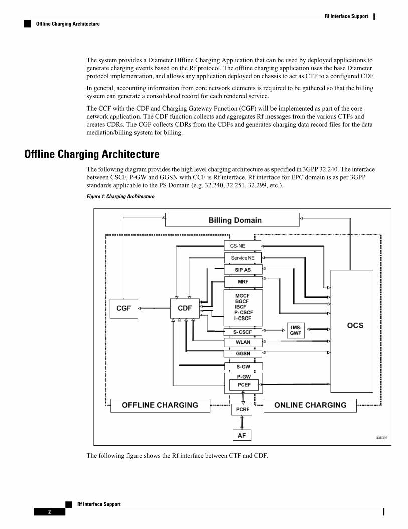
Offline Charging ArchitectureThe following diagram provides the high level charging architecture as specified in 3GPP 32.240. The interfacebetween CSCF, P-GW and GGSN with CCF is Rf interface. Rf interface for EPC domain is as per 3GPPstandards applicable to the PS Domain (e.g. 32.240, 32.251, 32.299, etc.).Figure 1: Charging Architecture
The following figure shows the Rf interface between CTF and CDF.
Rf Interface Support2
Rf Interface SupportOffline Charging Architecture

Figure 2: Logical Offline Charging Architecture
The Rf offline charging architecture mainly consists of three network elements CCF, CTF and DiameterDynamic Routing Agent (DRA).
Charging Collection FunctionThe CCF implements the CDF and CGF. The CCF will serve as the Diameter Server for the Rf interface. Allnetwork elements supporting the CTF function should establish a Diameter based Rf Interface over TCPconnections to the DRA. The DRA function will establish Rf Interface connection over TCP connections tothe CCF.
The CCF is primarily responsible for receipt of all accounting information over the defined interface and thegeneration of CDR (aka UDRs and FDRs) records that are in local storage. This data is then transferred tothe billing system using other interfaces. The CCF is also responsible for ensuring that the format of suchCDRs is consistent with the billing system requirements. The CDF function within the CCF generates andCGF transfers the CDRs to the billing system.
The CDF function in the CCF is responsible for collecting the charging information and passing it on to theappropriate CGF via the GTP' based interface per 3GPP standards. The CGF passes CDR files to billingmediation via SCP.
Charging Trigger FunctionThe CTF will generate CDR records and passes it onto CCF. When a P-GW service is configured as CTF,then it will generate Flow Data Record (FDR) information as indicated via the PCRF. The P-GW generatesRf messages on a per PDN session basis. There are no per UE or per bearer charging messages generated bythe P-GW.
The service data flows within IP-CAN bearer data traffic is categorized based on a combination of multiplekey fields (Rating Group, Rating Group and Service -Identifier). Each Service-Data-Container captures singlebi-directional flow or a group of single bidirectional flows as defined by Rating Group or Rating Group andService-Identifier.
Dynamic Routing AgentThe DRA provides load distribution on a per session basis for Rf traffic from CTFs to CCFs. The DRA actslike a Diameter Server to the Gateways. The DRA acts like a Diameter client to CCF. DRA appears to be aCCF to the CTF and as a CTF to the CCF.
The DRA routes the Rf traffic on a per Diameter charging session basis. The load distribution algorithm canbe configured in the DRA (Round Robin, Weighted distribution, etc). All Accounting Records (ACRs) in one
Rf Interface Support3
Rf Interface SupportCharging Collection Function

Diameter charging session will be routed by the DRA to the same CCF. Upon failure of one CCF, the DRAselects an alternate CCF from a pool of CCFs.
License RequirementsThe Rf interface support is a licensed Cisco feature. A separate feature license may be required. Contact yourCisco account representative for detailed information on specific licensing requirements. For information oninstalling and verifying licenses, refer to theManaging License Keys section of the Software ManagementOperations chapter in the System Administration Guide.
Supported StandardsRf interface support is based on the following standards:
• IETF RFC 4006: Diameter Credit Control Application; August 2005
• 3GPP TS 32.299 V9.6.0 (2010-12) 3rd Generation Partnership Project; Technical Specification GroupServices and System Aspects; Telecommunication management; Charging management; Diametercharging applications (Release9)
Features and TerminologyThis section describes features and terminology pertaining to Rf functionality.
Offline Charging ScenariosOffline charging for both events and sessions between CTF and the CDF is performed using the Rf referencepoint as defined in 3GPP TS 32.240.
Basic PrinciplesThe Diameter client and server must implement the basic functionality of Diameter accounting, as definedby the RFC 3588 Diameter Base Protocol.
For offline charging, the CTF implements the accounting state machine as described in RFC 3588. The CDFserver implements the accounting state machine "SERVER, STATELESS ACCOUNTING" as specified inRFC 3588, i.e. there is no order in which the server expects to receive the accounting information.
The reporting of offline charging events to the CDF is managed through the Diameter Accounting Request(ACR) message. Rf supports the following ACR event types:
Table 1: Rf ACR Event Types
DescriptionRequest
Starts an accounting sessionSTART
Updates an accounting sessionINTERIM
Stops an accounting sessionSTOP
Rf Interface Support4
Rf Interface SupportLicense Requirements

DescriptionRequest
Indicates a one-time accounting eventEVENT
ACR types START, INTERIM and STOP are used for accounting data related to successful sessions. Incontrast, EVENT accounting data is unrelated to sessions, and is used e.g. for a simple registration orinterrogation and successful service event triggered by a network element. In addition, EVENT accountingdata is also used for unsuccessful session establishment attempts.
The ACR Event Type "EVENT" is supported in Rf CDRs only in the case of IMS specific Rf implementation.Important
The following table describes all possible ACRs that might be sent from the IMS nodes i.e. a P-CSCF andS-CSCF.
Table 2: Accounting Request Messages Triggered by SIP Methods or ISUP Messages for P-CSCF and S-CSCF
Triggering SIP Method/ISUP MessageDiameter Message
SIP 200 OK acknowledging an initial SIP INVITEACR [Start]
ISUP:ANM (applicable for the MGCF)
SIP 200 OK acknowledging a SIPACR [Interim]
RE-INVITE or SIP UPDATE [e.g. change in mediacomponents]
Expiration of AVP [Acct-Interim-Interval]
SIP Response (4xx, 5xx or 6xx), indicating anunsuccessful SIP RE-INVITE or SIP UPDATE
SIP BYEmessage (both normal and abnormal sessiontermination cases)
ACR [Stop]
ISUP:REL (applicable for the MGCF)
Rf Interface Support5
Rf Interface SupportBasic Principles

Triggering SIP Method/ISUP MessageDiameter Message
SIP 200 OK acknowledging non-session related SIPmessages, which are:
• SIP NOTIFY
• SIP MESSAGE
• SIP REGISTER
• SIP SUBSCRIBE
• SIP PUBLISH
ACR [Event]
SIP 200 OK acknowledging an initial SIP INVITE
SIP 202 Accepted acknowledging a SIP REFER orany other method
SIP Final Response 2xx (except SIP 200 OK)
SIP Final/Redirection Response 3xx
SIP Final Response (4xx, 5xx or 6xx), indicating anunsuccessful SIP session set-up
SIP Final Response (4xx, 5xx or 6xx), indicating anunsuccessful session-unrelated procedure
SIP CANCEL, indicating abortion of a SIP sessionset-up
Event Based ChargingIn the case of event based charging, the network reports the usage or the service rendered where the serviceoffering is rendered in a single operation. It is reported using the ACR EVENT.
In this scenario, CTF asks the CDF to store event related charging data.
Session Based ChargingSession based charging is the process of reporting usage reports for a session and uses the START, INTERIM&STOP accounting data. During a session, a network element may transmit multiple ACR Interims' dependingon the proceeding of the session.
In this scenario, CTF asks the CDF to store session related charging data.
Diameter Base ProtocolTheDiameter Base Protocol maintains the underlying connection between the Diameter Client and the DiameterServer. The connection between the client and server is TCP based.
In order for the application to be compliant with the specification, state machines should be implemented atsome level within the implementation.
Rf Interface Support6
Rf Interface SupportEvent Based Charging

Diameter Base supports the following Rf message commands that can be used within the application.
Table 3: Diameter Rf Messages
AbbreviationDestinationSourceCommand Name
ACRCDFCTFAccounting-Request
ACACTFCDFAccounting-Answer
There are a series of other Diameter messages exchanged to check the status of the connection and thecapabilities.
• Capabilities Exchange Messages: Capabilities Exchange Messages are exchanged between the diameterpeers to know the capabilities of each other and identity of each other.
• Capabilities Exchange Request (CER): This message is sent from the client to the server to knowthe capabilities of the server.
• Capabilities Exchange Answer (CEA): This message is sent from the server to the client in responseto the CER message.
• Device Watchdog Request (DWR): After the CER/CEA messages are exchanged, if there is no moretraffic between peers for a while, to monitor the health of the connection, DWR message is sent fromthe client. The Device Watchdog timer (Tw) is configurable and can vary from 6 through 30 seconds. Avery low value will result in duplication of messages. The default value is 30 seconds. On two consecutiveexpiries of Tw without a DWA, the peer is considered to be down.
DWR is sent only after Tw expiry after the last message that came from the server.Say if there is continuous exchange of messages between the peers, DWR mightnot be sent if (Current Time - Last message received time from server) is lessthan Tw.
Important
• Device Watchdog Answer (DWA): This is the response to the DWR message from the server. This isused to monitor the connection state.
• Disconnect Peer Request (DPR): This message is sent to the peer to inform to shutdown the connection.There is no capability currently to send the message to the Diameter server.
• Disconnect Peer Answer (DPA): This message is the response to the DPR request from the peer. Onreceiving the DPR, the peer sends DPA and puts the connection state to "DO NOT WANT TO TALKTO YOU" state and there is no way to get the connection back except for reconfiguring the peer again.
A timeout value for retrying the disconnected peer must be provided.
Timer Expiry BehaviorUpon establishing the Diameter connection, an accounting interim timer (AII) is used to indicate the expirationof a Diameter accounting session, and is configurable at the CTF. The CTF indicates the timer value in theACR-Start, in the Acct-Interim-Interval AVP. The CDF responds with its own AII value (through the DRA),which must be used by the CTF to start a timer upon whose expiration an ACR INTERIM message must besent. An instance of the AII timer is started in the CCF at the beginning of the accounting session, reset on
Rf Interface Support7
Rf Interface SupportTimer Expiry Behavior

the receipt of an ACR-Interim and stopped on the receipt of the ACR-Stop. After expiration of the AII timer,ACR INTERIM message will be generated and the timer will be reset and the accounting session will becontinued.
Rf Interface Failures/Error ConditionsThe current architecture allows for primary and secondary connections or Active-Active connections for eachnetwork element with the CDF elements.
DRA/CCF Connection FailureWhen the connection towards one of the primary/Active DRAs in CCF becomes unavailable, the CTF picksthe Secondary/Active IP address and begins to use that as a Primary.
If no DRA (and/or the CCF) is reachable, the network element must buffer the generated accounting data innon-volatile memory. Once the DRA connection is up, all accounting messages must be pulled by the CDFthrough offline file transfer.
No Reply from CCFIn case the CTF/DRA does not receive an ACA in response to an ACR, it may retransmit the ACR message.The waiting time until a retransmission is sent, and the maximum number of repetitions are both configurableby the operator. When the maximum number of retransmissions is reached and still no ACA reply has beenreceived, the CTF/DRA sends the ACRs to the secondary/alternate DRA/CCF.
Detection of Message DuplicationThe Diameter client marks possible duplicate request messages (e.g. retransmission due to the link failoverprocess) with the T-flag as described in RFC 3588.
If the CDF receives a message that is marked as retransmitted and this message was already received, then itdiscards the duplicate message. However, if the original of the re-transmitted message was not yet received,it is the information in the marked message that is taken into account when generating the CDR. The CDRsare marked if information from duplicated message(s) is used.
CCF Detected FailureThe CCF closes a CDR when it detects that expected Diameter ACRs for a particular session have not beenreceived for a period of time. The exact behavior of the CCF is operator configurable.
Rf-Gy Synchronization EnhancementsBoth Rf (OFCS) and Gy (OCS) interfaces are used for reporting subscriber usage and billing. Since eachinterface independently updates the subscriber usage, there are potential scenarios where the reportedinformation is not identical. Apart from Quota enforcement, OCS is utilized for Real Time Reporting (RTR),which provides a way to the user to track the current usage and also get notifications when a certain thresholdis hit.
In scenarios where Rf (OFCS) and Gy (OCS) have different usage information for a subscriber session, it ispossible that the subscriber is not aware of any potential overages until billed (scenario when Rf is more thanGy) or subscriber believes he has already used up the quota whereas his actual billing might be less (scenariowhen Gy is more than Rf). In an attempt to align both the Rf and Gy reported usage values, release 12.3
Rf Interface Support8
Rf Interface SupportRf Interface Failures/Error Conditions

introduced capabilities to provide a way to get the reported values on both the interfaces to match as much aspossible. However, some of the functionalities were deferred and this feature implements the additionalenhancements.
In release 15.0 when time/volume quota on the Gy interface gets exhausted, Gy triggers "Service Data VolumeLimit" and "Service Data Time Limit". Now in 16.0 via this feature, this behavior is CLI controlled. Basedon the CLI command " trigger-type { gy-sdf-time-limit { cache | immediate } | gy-sdf-unit-limit { cache |immediate } | gy-sdf-volume-limit { cache | immediate } }" the behavior will be decided whether to sendthe ACR-Interim immediately or to cache the containers for future transactions. If the CLI for the event-triggersreceived via Gy is not configured, then those ACR-Interims will be dropped.
Releases prior to 16.0, whenever the volume/time-limit event triggers are generated, ACR-Interims were sentout immediately. In 16.0 and later releases, CLI configuration options are provided in policy accountingconfiguration to control the various Rf messages (ACRs) triggered for sync on this feature.
This release supports the following enhancements:
• Caches containers in scenarios when ACR-I could not be sent and reported to OFCS.
• Triggers ACR to the OFCS when the CCR to the OCS is sent instead of the current implementation ofwaiting for CCA from OCS.
If an ACR-I could not be sent to the OFCS, the PCEF caches the container record and sends it in the nexttransaction to the OFCS.
In releases prior to 16.0, once a CCR-U was sent out over Gy interface, ACR-I message was immediatelytriggered (or containers were cached) based on policy accounting configuration and did not wait for CCA-U.In 16.0 and later releases, the containers are closed only after receiving CCA-U successfully. That is, Rf triggerwill be sent only after receiving CCA-U message.
For more information on the command associated with this feature, see the Accounting Policy ConfigurationMode Commands chapter of the Command Line Interface Reference.
In 17.0 and later releases, a common timer based approach is implemented for Rf and Gy synchronization.As part of the new design, Gy and Rf will be check-pointed at the same point of time for periodic as well asfor full check-pointing. Thus, the billing records will always be in sync at all times regardless of during anICSR switchover event, internal events, session manager crashes, inactive Rf/Gy link, etc. This in turn avoidsany billing discrepancies.
Cessation of Rf Records When UE is IDLEReleases prior to 16.0, when the UE was identified to be in IDLE state and not sending any data, the P-GWgenerated Rf records. During this scenario, the generated Rf records did not include Service Data Containers(SDCs).
In 16.0 and later releases, the Rf records are not generated in this scenario. New CLI configuration command"session idle-mode suppress-interim" is provided to enable/disable the functionality at the ACR level tocontrol the behavior of whether an ACR-I needs to be generated or not when the UE is idle and no data istransferred.
That is, this CLI configuration is used to control sending of ACR-I records when the UE is in idle mode andwhen there is no data to report.
For more information on the command, see the Accounting Policy Configuration Mode Commands chapterof the Command Line Interface Reference.
Rf Interface Support9
Rf Interface SupportCessation of Rf Records When UE is IDLE
QoS Change Scenarios
QOS_CHANGE Trigger in Rf Records During eHRPD-LTE Handoff
In releases prior to 20, QOS_CHANGE is reported as the value for Change-Condition AVP in theService-Data-Container (SDC) of Rf accounting records (for accounting level SDF/SDF+accounting keysQCI) when eHRPD to LTE handoff occurs. Typically, the QOS_CHANGE should not be present as the PCRFdoes not enforce QoS via any QoS IE in eHRPD/CDMA RAT. In 20 and later releases, the SDC in thegenerated Rf record does not include QOS_CHANGE trigger during handoff from eHRPD to LTE.
QoS Change for Default Bearer
Releases prior to 20, in a multi-bearer call, when an update message (CCA-U or RAR) from PCRF changesthe QoS (QCI/ARP) of default bearer and in the same message installs a predefined or dynamic rule on thenewly updated default bearer, spurious Normal Release (NR) Service Data Volume (SDV) containers wereadded to Rf interim records for the dedicated bearers. In this scenario, the system used to send Normal Releasebuckets for the non-default bearers even if these bearers were not changed.
In release 20 and beyond, for a change in the QoS of default bearer, NR SDV containers will not be seenunless the corresponding bearer is torn down. Only QoS change containers are closed/released for the bearerthat underwent QoS Change, i.e. the default bearer.
Diameter Rf Duplicate Record GenerationThis section describes the overview and implementation of Rf Duplicate Record Generation feature.
This section discusses the following topics for this feature:
• Feature Description, on page 10
• Configuring Rf Duplicate Record Generation, on page 12
• Monitoring and Troubleshooting the Rf Duplicate Record Generation, on page 14
Feature DescriptionThis feature is introduced to support creation and communication of duplicate Rf records to secondary AAAgroup servers configured for the Rf interface.
To achieve this functionality, the following configurations must be enabled –
• aaa groupCLI command under APN to configure amaximum of 2AAAgroups - primary and secondaryAAA groups, or two different endpoints for Rf Diameter accounting servers
• diameter accounting duplicate-record under AAA group to allow Rf duplicate record creation
The diameter accounting duplicate-record is a new CLI command introduced in this release for duplicatingthe Rf START, INTERIM and STOP accounting records.
This is a license-controlled CLI command. For more information, contact your Cisco account representative.Important
Rf Interface Support10
Rf Interface SupportQoS Change Scenarios

In releases prior to 21, gateway allows only one AAA group configuration per APN for Rf accounting. TheAAA group is configured to load balance across multiple servers to pass the Rf traffic and also expect anaccounting answer. Note that the secondary AAA group configuration is allowed currently but is restrictedto only RADIUS accounting.
In release 21 and beyond, the gateway is provided with the ability to configure a secondary AAA group perAPN for the Rf interface, and send the duplicate Diameter Rf accounting records to the secondary AAA groupservers. The secondary AAA group is used for non-billing purposes only.
The failed duplicate records will neither be written to HDD nor added to the archival list.Important
There is no change in the current behavior with the primary AAA group messages. The primary AAA groupis independent of the secondary AAA group, and it has multiple Rf servers configured. When the Rf serversdo not respond even after multiple retries as per the applicable configuration, the Rf records are archived andstored in HDD. This behavior continues as is irrespective of the configuration of secondary aaa-group.
Secondary aaa group has a very similar configuration as the primary aaa group except that the new CLIcommand diameter accounting duplicate-record is additionally included to configure the secondary aaa-group.It is also important to note that different Diameter endpoints and a separate set of Rf servers should beprovisioned for both primary and secondary AAA groups.
If all the configured servers are down, the request message will be discarded without writing it in HDD orarchiving at aaamgr.
The original and duplicate Rf messages use two different aaa-groups and two different Diameter endpoints.Hence, the values for Session-ID AVP will be different. Based on the configuration of primary and secondaryendpoints the values for Origin-Host, Origin-Realm, Destination-Realm, and Destination-Host AVPs may bedifferent. Also based on the configuration under policy accounting for inclusion of virtual/gn apn name forsecondary group Called-Station-ID AVP might change. All other AVPs will have the same values as with theprimary aaa group Rf message.
Also, note that the values such as Acct-Interim-Interval (AII) interval received in ACA from secondary groupof AAA servers will be ignored.
Relationships to Other Features
This feature can be used in conjunction with Virtual APN Truncation feature to achieve the desired results.
The Virtual APN Truncation feature is new in release 21. For more information on this feature, see theadministration guide for the product you are deploying.
Limitations
The following are the limitations of this feature:
• Only one secondary AAA group can be configured per APN.
• If all the Rf peers under secondary aaa group are down and duplicate Start Record is not sent, then theduplicate Interim and Stop records will also not be sent to any of the secondary aaa group servers eventhough they arrived later. However if the servers are up and duplicate Start record was sent but the serverdid not respond, duplicate Start will be dropped after all the retries. In this case, the duplicate Interimand Stop records may be sent out to the server.
Rf Interface Support11
Rf Interface SupportFeature Description

• In cases when duplicate Start record was sent, but during duplicate Interim/Stop record generation peerswere not responding/down, after all retries duplicate Interim and Stop records will be dropped and willnot be written to HDD.
• Minimal impact to memory and CPU is expected due to the duplicate record generation for every primaryRf record.
Configuring Rf Duplicate Record GenerationThe following section provides the configuration commands to enable the Rf duplicate record generation.
Configuring Secondary AAA Group
Use the following configuration commands to configure the secondary AAA group for receiving the duplicateRf records.
configurecontext context_name
apn apn_name
aaa group group_name
aaa secondary-group group_name
exit
Notes:
• aaa group group_name: Specifies the AAA server group for the APN. group_name must be analphanumeric string of 1 through 63 characters.
• secondary group group_name: Specifies the secondary AAA server group for the APN. group_namemust be an alphanumeric string of 1 through 63 characters.
Configuring Duplication of Rf Records
Use the following configuration commands to configure the system to create a secondary feed of Rf recordsand send them to the secondary AAA group.
configurecontext context_name
aaa group group_name
diameter accounting duplicate-recordexit
Notes:
• duplicate-record: Sends duplicate Rf records to configured secondary AAA group. This keyword islicense dependent. For more information, contact your Cisco account representative.
• The default configuration is no diameter accounting duplicate-record. By default, this feature isdisabled.
• The secondary aaa groupmust be configured under APN configurationmode before enabling the diameteraccounting duplicate-record CLI command.
Verifying the Rf Duplicate Record Generation Configuration
Use the following commands to verify the configuration status of this feature.
Rf Interface Support12
Rf Interface SupportConfiguring Rf Duplicate Record Generation

show configuration
show aaa group all
- or -
show aaa group group_name
group_name must be the name of the AAA group specified during the configuration.
This command displays all the configurations that are enabled within the specified AAA group.
The following is a sample configuration of this feature.
configurecontext source
apn domainname.com
associate accounting-policy policy_accounting_name
aaa group group1
aaa secondary-group group2
exitaaa group group1
diameter accounting dictionary aaa-custom4diameter accounting endpoint rf_endpoint1
diameter accounting server rf_server1 priority 1
diameter accounting server rf_server2 priority 2
exitaaa group group2
diameter accounting dictionary aaa-custom4diameter accounting endpoint rf_endpoint2
diameter accounting duplicate-recorddiameter accounting server rf_server3 priority 3
diameter accounting server rf_server4 priority 4
exitdiameter endpoint rf-endpoint1
use-proxyorigin host rf-endpoint1.carrier.com address 192.50.50.3
no watchdog-timeoutresponse-timeout 20
connection retry-timeout 5
peer rf_server1 realm domainname.com address 192.50.50.4 port 4872
peer rf_server2 realm domainname.com address 192.50.50.4 port 4873
exitdiameter endpoint rf-endpoint2
use-proxyorigin host rf-endpoint2.carrier.com address 192.50.50.2
no watchdog-timeoutresponse-timeout 20
connection retry-timeout 5
peer rf_server3 realm domainname.com address 192.50.50.5 port 4892
peer rf_server4 realm domainname.com address 192.50.50.5 port 4893
end
Notes:
Rf Interface Support13
Rf Interface SupportVerifying the Rf Duplicate Record Generation Configuration

• The diameter accounting duplicate-record CLI is license specific. So, the corresponding license mustbe enabled for the CLI command to be configured.
• Both primary and secondary aaa groups are preferred to have different accounting endpoint names.
Monitoring and Troubleshooting the Rf Duplicate Record GenerationThis section provides information regarding show commands and/or their outputs in support of this feature.
The following operations can be performed to troubleshoot any failure related to this feature:
• Verify if the feature is enabled using show configuration or show aaa group all CLI command. If notenabled, configure the diameter accounting duplicate-record CLI command and check if it works.
• Collect the output of show diameter aaa statistics command and analyze the debug statistics. Also,check the reported logs, if any. For further analysis, contact Cisco account representative.
show diameter aaa-statistics
The following statistics are added to the output of this show command for duplicate Rf records which weredropped because of the failure in sending the Accounting records instead of adding them to HDD or archivallist.
• Duplicate Accounting Records Stats
• ACR-Start Dropped
• ACR-Interim Dropped
• ACR-Stop Dropped
These statistics are maintained per aaamgr instance level. For descriptions of these statistics, see the Statisticsand Counters Reference guide.
These statistics can also be collected per group basis/server basis for duplicate records i.e. through showdiameter aaa-statistics group <group_name> and show diameter aaa-statistics server <server_name>CLI commands.
Truncation of Virtual APN for Rf RecordsThis feature enables the truncation of Virtual APN (VAPN) returned by S6b server to be sent to Gx, Gy andRf interfaces.
Feature DescriptionCurrently there is no way to quickly turn on the Rf accounting to the Data Streaming Service (DSS) serverper Virtual APN (S6b-VAPN) without reaching all nodes in the network and provision the Virtual APN oneach of them. This feature is implemented to truncate the virtual APN name returned by S6b server with theconfigured standard delimiters. In this way a single configuration per node can be utilized for all enterprisesbased on a virtual APN. This approach will significantly reduce the size and time to provision new enterpriseswith the requested feature.
Rf Interface Support14
Rf Interface SupportMonitoring and Troubleshooting the Rf Duplicate Record Generation
To achieve this functionality, a configuration is added per APN to enable truncation of S6b-VAPN and alsoto configure the delimiter(s) where the APN name is to be truncated. Standard delimiters like (.) and (-) areused since APN name supports only these two characters apart from the alphanumeric ones.
If AAA server returns both hyphen and dot delimiters or the same delimiter twice or more as a virtual-apn,then the first delimiter will be considered as a separator. For example, if the AAA server returns the virtual-apnas xyz-cisco.com, then hyphen is the separator.
AAAmanager performs the truncation of the Virtual APN name based on the APN configuration and providesthe correct APN profile for the truncated APN name. If the truncation is successful, the full virtual APN namewill be sent to Gx, Gy and Rf interfaces.
Accounting records are required to support real-time usage notification and device management functionality.So, the apn-name-to-be-includedCLI command is extended to enable actual APN (Gn-APN) or virtual APN(S6b returned virtual APN) name to be included in Called-Station-ID AVP in the secondary Rf accountingrecords (secondary server group) under policy accounting configuration. Currently, policy accountingconfiguration supports sending the Gn-APN/S6b-VAPN in Called-Station-ID for primary Rf server. Withthis CLI command, this functionality is extended for the secondary Rf server.
A new AAA attribute “Secondary-Called-Station-ID” is added to support sending Gn/Virtual APN name inthe Called-Station-ID AVP for duplicate Rf records sent to secondary group Rf server.
Configuring Virtual APN Truncation for Rf RecordsThe following section provides the configuration commands to enable the Virtual APN Truncation featurefor Rf records.
Configuring Gn-APN/VAPN for Rf Accounting
Use the following configuration commands to configure the actual APN or Virtual APN (VAPN) for Rfaccounting.
configurecontext context_name
policy accounting policy_name
apn-name-to-be-included { gn | virtual } [ secondary-group { gn |virtual } ]
end
Notes:
• apn-name-to-be-included: Configures the APN name to be included in the Rf messages for primaryserver group.
• secondary-group { gn | virtual }: Configures the APN name to be included in the Rf messages forsecondary server group.
• gn: Configures the Gn APN name to be included in the Rf messages.
• virtual: Configures the virtual APN name to be included in the Rf messages.
• By default, the apn name to be included in Called-Station-ID AVP is Gn-APN for both primary andsecondary Rf server groups.
• If the secondary group configuration is not available, the default behavior is to have GnAPN for secondaryRf group duplicate records.
Rf Interface Support15
Rf Interface SupportConfiguring Virtual APN Truncation for Rf Records

Configuring Truncation of Virtual APN
Use the following configuration commands to configure the gateway to truncate the APN name returned fromS6b interface.
configurecontext context_name
apn apn_name
virtual-apn { gcdr apn-name-to-be-included { gn | virtual } |truncate-s6b-vapn delimiter { dot [ hyphen ] | hyphen [ dot ] } }
end
Notes:
• For information on the existing keywords, see the Command Line Interface Reference guide.
• truncate-s6b-vapn: Allows truncation of virtual APN received from S6b at the configured delimitercharacter.
• delimiter { dot [ hyphen ] | hyphen [ dot ] }: Configures the delimiter for truncation of virtual APNreceived from S6b. If the CLI command is configured, the S6b returned virtual APN will be truncatedat the configured delimiter.
• dot: Configures the delimiter to dot (.) for truncation of S6b-VAPN
• hyphen: Configures the delimiter to hyphen (-) for truncation of S6b-VAPN
• Both dot and hyphen delimiters can be configured in the same line or a new line.
• no virtual-apn truncate-s6b-vapn: Disables the truncation of virtual APN name. If both delimitersshould be disabled at once, use the no virtual-apn truncate-s6b-vapn CLI command.
If a particular delimiter needs to disabled, it should be done explicitly. For example, if the dot delimitershould be disabled, use the no virtual-apn truncate-s6b-vapn delimiter dot CLI command.
• By default this feature will be disabled and no delimiter will be configured.
• This CLI command takes effect only when S6b server returns virtual APN name in AuthenticationAuthorization Accept (AAA) message.
• If the separator character is not present in the received S6b virtual APN name, then the whole virtualAPN name will be considered for configuration look-up.
Verifying the Virtual APN Truncation Configuration
Use the following command to verify the configuration status of this feature.
show configuration apn apn_name
apn_name must be the name of the APN specified during the feature configuration.
This command displays all the configurations that are enabled within the specified APN name. The followingis a sample output of this show command.[local]st40# show configuration apn intershatconfigure
context ingressapn intershat
pdp-type ipv4 ipv6bearer-control-mode mixed
Rf Interface Support16
Rf Interface SupportConfiguring Truncation of Virtual APN

virtual-apn truncate-s6b-vapn delimiter hyphenend
Monitoring and Troubleshooting the Virtual APN TruncationThis section provides information regarding show commands and/or their outputs in support of this feature.
The following operations can be performed to troubleshoot any failure related to this feature:
• Verify if the feature is enabled using show configuration apn apn_name CLI command. If not enabled,configure the virtual-apn truncate-s6b-vapn delimiter { dot [ hyphen ] | hyphen [ dot ] } } CLIcommand and check if it works.
• Collect the output of show apn statistics CLI command and analyze the debug statistics. For furtherassistance, contact Cisco account representative.
For P-GW, GGSN and SAEGW services, if the truncation of S6b returned virtual APN name fails and thevirtual APN name is not configured, the call will be rejected with ‘unknown-apn-name’ cause.
Important
show apn statistics
This show command uses the existing APN statistics to populate the truncated virtual APN name, if thisfeature is enabled.
show subscribers ggsn-only full all
The following field added newly to the output of this show command displays the S6b returned full virtualAPN name, if this feature is enabled. Otherwise, it displays 'n/a’.
• S6b Returned Virtual APN
show subscribers pgw-only full all
The following field added newly to the output of this show command displays the S6b returned full virtualAPN name, if this feature is enabled. Otherwise, it displays 'n/a’.
• S6b Returned Virtual APN
show subscribers saegw-only full all
The following field added newly to the output of this show command displays the S6b returned full virtualAPN name, if this feature is enabled. Otherwise, it displays 'n/a’.
• S6b Returned Virtual APN
How it WorksThis section describes how offline charging for subscribers works with Rf interface support inGPRS/eHRPD/LTE/IMS networks.
Rf Interface Support17
Rf Interface SupportMonitoring and Troubleshooting the Virtual APN Truncation

The following figure and table explain the transactions that are required on the Diameter Rf interface in orderto perform event based charging. The operation may alternatively be carried out prior to, concurrently withor after service/content delivery.Figure 3: Rf Call Flow for Event Based Charging
Table 4: Rf Call Flow Description for Event Based Charging
DescriptionStep
The network element (CTF) receives indication thatservice has been used/delivered.
1
The CTF (acting as Diameter client) sendsAccounting-Request (ACR) withAccounting-Record-Type AVP set toEVENT_RECORD to indicate service specificinformation to the CDF (acting as Diameter server).
2
The CDF receives the relevant service chargingparameters and processes accounting request.
3
TheCDF returnsAccounting-Answer (ACA)messagewith Accounting-Record-Type AVP set toEVENT_RECORD to the CTF in order to inform thatcharging information was received.
4
The following figure and table explain the simple Rf call flow for session based charging.
Rf Interface Support18
Rf Interface SupportHow it Works

Figure 4: Rf Call Flow for Session Based Charging
Table 5: Rf Call Flow Description for Session Based Charging
DescriptionStep
The CTF receives a service request. The servicerequest may be initiated either by the user or the othernetwork element.
1
In order to start accounting session, the CTF sends aAccounting-Request (ACR) withAccounting-Record-Type AVP set toSTART_RECORD to the CDF.
2
The session is initiated and the CDF opens a CDR forthe current session.
3
TheCDF returnsAccounting-Answer (ACA)messagewith Accounting-Record-Type set toSTART_RECORD to the CTF and possiblyAcct-Interim-Interval AVP (AII) set to non-zero valueindicating the desired intermediate charging interval.
4
Rf Interface Support19
Rf Interface SupportHow it Works

DescriptionStep
When either AII elapses or charging condition changesare recognized at CTF, the CTF sends anAccounting-Request (ACR) withAccounting-Record-Type AVP set toINTERIM_RECORD to the CDF.
5
The CDF updates the CDR in question.6
TheCDF returnsAccounting-Answer (ACA)messagewith Accounting-Record-Type set toINTERIM_RECORD to the CTF.
7
The service is terminated.8
The CTF sends a Accounting-Request (ACR) withAccounting-Record-Type AVP set toSTOP_RECORD to the CDF.
9
The CDF updates the CDR accordingly and closesthe CDR.
10
TheCDF returnsAccounting-Answer (ACA)messagewithAccounting-Record-Type set to STOP_RECORDto the CTF.
11
Configuring Rf Interface SupportTo configure Rf interface support:
1. Configure the core network service as described in this Administration Guide.
2. Enable Active Charging Service (ACS) and create ACS as described in the Enhanced Charging ServicesAdministration Guide.
The procedures in this section assume that you have installed and configured your chassis including the ECSinstallation and configuration as described in the Enhanced Charging Services Administration Guide.
Important
3. Enable Rf accounting in ACS as described in Enabling Rf Interface in Active Charging Service, on page21.
4. Configure Rf interface support as described in the relevant sections:
• Configuring GGSN / P-GW Rf Interface Support, on page 21• Configuring P-CSCF/S-CSCF Rf Interface Support, on page 36
In StarOS versions 19 and later, the Rf interface is not supported on the S-GW.Important
Rf Interface Support20
Rf Interface SupportConfiguring Rf Interface Support

5. Save your configuration to flash memory, an external memory device, and/or a network location usingthe Exec mode command save configuration. For additional information on how to verify and saveconfiguration files, refer to the System Administration Guide and the Command Line Interface Reference.
Commands used in the configuration examples in this section provide base functionality to the extent that themost common or likely commands and/or keyword options are presented. In many cases, other optionalcommands and/or keyword options are available. Refer to theCommand Line Interface Reference for completeinformation regarding all commands.
Important
Enabling Rf Interface in Active Charging ServiceTo enable the billing record generation and Rf accounting, use the following configuration:
configureactive-charging service <service_name>
rulebase <rulebase_name>
billing-records rfactive-charging rf { rating-group-override | service-id-override
}end
Notes:
• Prior to creating the Active Charging Service (ACS), the require active-charging command should beconfigured to enable ACS functionality.
After you configure this command, you must save the configuration and thenreload the chassis for the command to take effect. For information on saving theconfiguration file and reloading the chassis, refer to the System AdministrationGuide for your deployment.
Important
• The billing-records rf command configures Rf record type of billing to be performed for subscribersessions. Rf accounting is applicable only for dynamic and predefined ACS rules.
For more information on the rules and its configuration, refer to the ACS Charging Action ConfigurationMode Commands chapter in the Command Line Interface Reference.
• The active-charging rf command is used to enforce a specific rating group / service identifier on allPCC rules, predefined ACS rules, and static ACS rules for Rf-based accounting. As this CLI configurationis applied at the rulebase level, all the APNs that have the current rulebase defined will inherit theconfiguration.
For more information on this command, refer to the ACS Rulebase Configuration Mode Commandschapter in the Command Line Interface Reference.
Configuring GGSN / P-GW Rf Interface SupportTo configure the standard Rf interface support for GGSN/P-GW, use the following configuration:
Rf Interface Support21
Rf Interface SupportEnabling Rf Interface in Active Charging Service

configurecontext <context_name>
apn <apn_name>
associate accounting-policy <policy_name>
exitpolicy accounting <policy_name>
accounting-event-trigger { cgi-sai-change | ecgi-change |flow-information-change | interim-timeout | location-change | rai-change| tai-change } action { interim | stop-start }
accounting-keys qciaccounting-level { flow | pdn | pdn-qci | qci | sdf | subscriber }
cc profile index { buckets num | interval seconds | sdf-intervalseconds | sdf-volume { downlink octets { uplink octets } | total octets |uplink octets { downlink octets } } | serving-nodes num | tariff time1 min
hrs [ time2 min hrs...time4 min hrs ] | volume { downlink octets { uplink octets
} | total octets | uplink octets { downlink octets } } }max-containers { containers | fill-buffer }end
Notes:
• The policy can be configured in any context.
• For information on configuring accounting levels/policies/modes/event triggers, refer to the AccountingPolicy Configuration Mode Commands chapter in the Command Line Interface Reference.
• Depending on the triggers configured, the containers will either be cached or released. In the case ofGGSN/P-GW, the containers will be cached when the event trigger is one of the following:
• QOS_CHANGE• FLOW_INFORMATION_CHANGE• LOCATION_CHANGE• SERVING_NODE_CHANGE• SERVICE_IDLE• SERVICE_DATA_VOLUME_LIMIT• SERVICE_DATA_TIME_LIMIT• IP_FLOW_TERMINATION• TARIFF_CHANGE
If the event trigger is one of the following, the containers will be released:
• VOLUME_LIMIT• TIME_LIMIT• RAT_CHANGE• TIMEZONE_CHANGE• PLMN_CHANGE
Currently, SDF and flow level accounting are supported in P-GW.Important
The following assumptions guide the behavior of P-GW, GGSN and CCF for Change-Condition triggers:
Rf Interface Support22
Rf Interface SupportConfiguring GGSN / P-GW Rf Interface Support

• Data in the ACR messages due to change conditions contain the snapshot of all data that is applicableto the interval of the flow/session from the previous ACR message. This includes all data that is alreadysent and has not changed (e.g. SGSN-Address).
• All information that is in a PDN session/flow up to the point of the Change-Condition trigger is captured(snapshot) in the ACR-Interim messages. Information about the targetTime-Zone/ULI/3GPP2-BSID/QoS-Information/PLMN Change/etc will be in subsequent Rf messages.
Table 6: P-GW/GGSN and CCF Behavior for Change-Condition in ACR-Stop and ACR-Interim for LTE/e-HRPD/GGSN
CommentsCC Level PopulationCCF Response to Change-Condition ValueChange-ConditionValue
ACR Message
SDC LevelPS-InformationLevel
Final FDRPartial FDRAddition ofContainer
WhenPDN/IPsession isclosed, C-Cin both levelwill haveNormalRelease.
NormalRelease
NormalRelease
YESNOYESNormalRelease
Stop
Flow isclosed, SDCCC ispopulatedand closedcontainer isadded torecord. Thecontainer forthis changeconditionwill becached bytheP-GW/GGSNand thecontainerwill be in aACRInterim/Stopsent forpartial record(Interim),final Record(Stop) or AIItrigger(Interim)trigger.
NormalRelease
N/ANONOYESNormalRelease
None (as this changecondition is a counter for theMax Number of Changes inCharging Conditions).
Rf Interface Support23
Rf Interface SupportConfiguring GGSN / P-GW Rf Interface Support

CommentsCC Level PopulationCCF Response to Change-Condition ValueChange-ConditionValue
ACR Message
SDC LevelPS-InformationLevel
Final FDRPartial FDRAddition ofContainer
WhenPDN/IPsession isclosed, C-Cin both levelwill haveAbnormalRelease.
AbnormalRelease
AbnormalRelease
YESNOYESAbnormalRelease
Stop
Flow isclosed, SDCCC ispopulatedand closedcontainer isadded torecord. Thecontainer forthis changeconditionwill becached bytheP-GW/GGSNand thecontainerwill be in aACRInterim/Stopsent forpartial record(Interim),final Record(Stop) or AIItrigger(Interim)trigger.
AbnormalRelease
N/ANONOYESAbnormalRelease
None (as this changecondition is a counter for theMax Number of Changes inCharging Conditions).
Rf Interface Support24
Rf Interface SupportConfiguring GGSN / P-GW Rf Interface Support

CommentsCC Level PopulationCCF Response to Change-Condition ValueChange-ConditionValue
ACR Message
SDC LevelPS-InformationLevel
Final FDRPartial FDRAddition ofContainer
Thecontainer forthis changeconditionwill becached bytheP-GW/GGSNand thecontainerwill be in aACRInterim/Stopsent forpartial record(Interim),final Record(Stop) or AIItrigger(Interim)trigger.
QoS-ChangeN/ANONOYESQoS-ChangeNone (as this changecondition is a counter for theMax Number of Changes inCharging Conditions).
Rf Interface Support25
Rf Interface SupportConfiguring GGSN / P-GW Rf Interface Support

CommentsCC Level PopulationCCF Response to Change-Condition ValueChange-ConditionValue
ACR Message
SDC LevelPS-InformationLevel
Final FDRPartial FDRAddition ofContainer
For PDN/IPSessionVolumeLimit. TheVolumeLimit isconfigured aspart of theChargingprofile andtheCharging-CharacteristicsAVP willcarry thischargingprofile thatwill passedon from theHSS/AAA toP-GW/GGSNthroughvariousinterfaces.The chargingprofile willbeprovisionedin the HSS.
VolumeLimit
VolumeLimit
NOYESYESVolumeLimit
Interim
Rf Interface Support26
Rf Interface SupportConfiguring GGSN / P-GW Rf Interface Support

CommentsCC Level PopulationCCF Response to Change-Condition ValueChange-ConditionValue
ACR Message
SDC LevelPS-InformationLevel
Final FDRPartial FDRAddition ofContainer
For PDN/IPSession TimeLimit. TheTime Limitis configuredas part of theChargingprofile andtheCharging-CharacteristicsAVP willcarry thischargingprofile thatwill passedon from theHSS/AAA toP-GW/GGSNthroughvariousinterfaces.The chargingprofile willbeprovisionedin the HSS.
Time LimitTime LimitNOYESYESTime LimitInterim
Rf Interface Support27
Rf Interface SupportConfiguring GGSN / P-GW Rf Interface Support

CommentsCC Level PopulationCCF Response to Change-Condition ValueChange-ConditionValue
ACR Message
SDC LevelPS-InformationLevel
Final FDRPartial FDRAddition ofContainer
Thecontainer forthis changeconditionwill becached bytheP-GW/GGSNand thecontainerwill be in aACRInterim/Stopsent forpartial record(Interim),final Record(Stop) or AIItrigger(Interim)trigger.
ServingNodeChange
N/ANONOYESServingNodeChange
None (as this changecondition is a counter for theMax Number of Changes inCharging Conditions).
ServingNode PLMNChange
ServingNode PLMNChange
NOYESYESServingNode PLMNChange
Interim
Rf Interface Support28
Rf Interface SupportConfiguring GGSN / P-GW Rf Interface Support

CommentsCC Level PopulationCCF Response to Change-Condition ValueChange-ConditionValue
ACR Message
SDC LevelPS-InformationLevel
Final FDRPartial FDRAddition ofContainer
This is BSIDChange ineHRPD. Thecontainer forthis changeconditionwill becached bytheP-GW/GGSNand thecontainerwill be in aACRInterim/Stopsent forpartial record(Interim),final Record(Stop) or AIItrigger(Interim)trigger.
UserLocationChange
N/ANONOYESUserLocationChange
None (as this changecondition is a counter for theMax Number of Changes inCharging Conditions).
RAT ChangeRAT ChangeNOYESYESRAT ChangeInterim
This is notapplicablefor eHRPD.
UETimezonechange
UETimezonechange
NOYESYESUETimezoneChange
Interim
Rf Interface Support29
Rf Interface SupportConfiguring GGSN / P-GW Rf Interface Support

CommentsCC Level PopulationCCF Response to Change-Condition ValueChange-ConditionValue
ACR Message
SDC LevelPS-InformationLevel
Final FDRPartial FDRAddition ofContainer
Triggeredwhen TariffTimechanges.Tariff TimeChangerequires anonlinecharging sidechange. Theimplementationof thisChangeCondition isdependent onimplementationof OnlineChargingupdate.
Tariff TimeChange
N/ANONOYESTariff TimeChange
None (as this changecondition is a counter for theMax Number of Changes inCharging Conditions).
Flow Idledout. Thecontainer forthis changeconditionwill becached bytheP-GW/GGSNand thecontainerwill be in aACRInterim/Stopsent forpartial record(Interim),final Record(Stop) or AIItrigger(Interim)trigger.
Service IdledOut
N/ANONOYESService IdledOut
None (as this changecondition is a counter for theMax Number of Changes inCharging Conditions).
Rf Interface Support30
Rf Interface SupportConfiguring GGSN / P-GW Rf Interface Support

CommentsCC Level PopulationCCF Response to Change-Condition ValueChange-ConditionValue
ACR Message
SDC LevelPS-InformationLevel
Final FDRPartial FDRAddition ofContainer
VolumeLimitreached for aspecific flow.Thecontainer forthis changeconditionwill becached bytheP-GW/GGSNand thecontainerwill be in aACRInterim/Stopsent forpartial record(Interim),final Record(Stop) or AIItrigger(Interim)trigger.
Service DataVolumeLimit
N/ANONOYESService DataVolumeLimit
None (as this changecondition is a counter for theMax Number of Changes inCharging Conditions).
Rf Interface Support31
Rf Interface SupportConfiguring GGSN / P-GW Rf Interface Support

CommentsCC Level PopulationCCF Response to Change-Condition ValueChange-ConditionValue
ACR Message
SDC LevelPS-InformationLevel
Final FDRPartial FDRAddition ofContainer
Time Limitreached for aspecific flow.Thecontainer forthis changeconditionwill becached bytheP-GW/GGSNand thecontainerwill be in aACRInterim/Stopsent forpartial record(Interim),final Record(Stop) or AIItrigger(Interim)trigger.
Service DataTime Limit
N/ANONOYESService DataTime Limit
None (as this changecondition is a counter for theMax Number of Changes inCharging Conditions).
Rf Interface Support32
Rf Interface SupportConfiguring GGSN / P-GW Rf Interface Support

CommentsCC Level PopulationCCF Response to Change-Condition ValueChange-ConditionValue
ACR Message
SDC LevelPS-InformationLevel
Final FDRPartial FDRAddition ofContainer
YES, Willinclude SDCthatcorreponds tothe CCs thatoccurred(NormalRelease ofFlow,AbnormalRelease ofFlow,QoS-Change,ServingNodeChange,UserLocationChange,Tariff TimeChange,Service IdledOut, ServiceDataVolunmeLimt, ServiceData TimeLimit)
YESNOYESYESMaxNumberof Changesin ChargingConditions
Interim
Rf Interface Support33
Rf Interface SupportConfiguring GGSN / P-GW Rf Interface Support

CommentsCC Level PopulationCCF Response to Change-Condition ValueChange-ConditionValue
ACR Message
SDC LevelPS-InformationLevel
Final FDRPartial FDRAddition ofContainer
ThisACR[Interim]is triggeredat the instantwhen theMaxNumberof changes inchargingconditionstakes place.Max ChangeCondition isapplicableforQoS-Change,Service-IdledOut, ULIchange, FlowNormalRelease,FlowAbnormalRelease,Service DataVolumeLimit,Service DataTime Limit,AII TimerACR Interimand ServiceNodeChangeCC only. TheMaxNumberof Changesin ChargingConditions isset at 10.Exampleassuming 1flow in thePDNSession: [1]MaxNumberof Changesin ChargingConditions
Rf Interface Support34
Rf Interface SupportConfiguring GGSN / P-GW Rf Interface Support

CommentsCC Level PopulationCCF Response to Change-Condition ValueChange-ConditionValue
ACR Message
SDC LevelPS-InformationLevel
Final FDRPartial FDRAddition ofContainer
set atP-GW/GGSN= 2. [2]ChangeCondition 1takes place.No ACRInterim issent.P-GW/GGSNstores theSDC. [3]ChangeCondition 2takes place.An ACRInterim issent. NowMaxNumberof Changesin Chargingconditions ispopulated inthePS-Information2Service-Data-Containers(1 for eachchangecondition)are populatedin the ACRInterim. [4]CCF createsthe partialrecord.
Managementinterventionwill close thePDN sessionfromP-GW/GGSN.
YESYESYESNOYESManagementIntervention
Stop
Rf Interface Support35
Rf Interface SupportConfiguring GGSN / P-GW Rf Interface Support

CommentsCC Level PopulationCCF Response to Change-Condition ValueChange-ConditionValue
ACR Message
SDC LevelPS-InformationLevel
Final FDRPartial FDRAddition ofContainer
This isincluded hereto indicatethat anACR[Interim]due to AIItimer willcontain oneor morepopulatedSDC/s fora/all flow/s,butChange-ConditionAVP willNOT bepopulated.
N/AN/ANONOYES-Interim
Configuring P-CSCF/S-CSCF Rf Interface SupportTo configure P-CSCF/S-CSCF Rf interface support, use the following configuration:
configurecontext vpn
aaa group default
diameter authentication dictionary aaa-custom8diameter accounting dictionary aaa-custom2diameter accounting endpoint <endpoint_name>
diameter accounting server <server_name> priority <priority>
exitdiameter endpoint <endpoint_name>
origin realm <realm_name>
use-proxyorigin host <host_name> address <ip_address>
peer <peer_name> address <ip_address>
exitend
Notes:
• For information on commands used in the basic configuration for Rf support, refer to the Command LineInterface Reference.
Gathering StatisticsThis section explains how to gather Rf and related statistics and configuration information.
Rf Interface Support36
Rf Interface SupportConfiguring P-CSCF/S-CSCF Rf Interface Support

In the following table, the first column lists what statistics to gather, and the second column lists the actionto perform.
Action to performStatistics/Information
show diameter aaa-statisticsComplete statistics for Diameter Rf accountingsessions
The following is a sample output of the show diameter aaa-statistics command:Authentication Servers Summary-------------------------------Message Stats :Total MA Requests: 0 Total MA Answers: 0MAR - Retries: 0 MAA Timeouts: 0MAA - Dropped: 0Total SA Requests: 0 Total SA Answers: 0SAR - Retries: 0 SAA Timeouts: 0SAA - Dropped: 0Total UA Requests: 0 Total UA Answers: 0UAR - Retries: 0 UAA Timeouts: 0UAA - Dropped: 0Total LI Requests: 0 Total LI Answers: 0LIR - Retries: 0 LIA Timeouts: 0LIA - Dropped: 0Total RT Requests: 0 Total RT Answers: 0RTR - Rejected: 0Total PP Requests: 0 Total PP Answers: 0PPR - Rejected: 0Total DE Requests: 0 Total DE Answers: 0DEA - Accept: 0 DEA - Reject: 0DER - Retries: 0 DEA Timeouts: 0DEA - Dropped: 0Total AA Requests: 0 Total AA Answers: 0AAR - Retries: 0 AAA Timeouts: 0AAA - Dropped: 0ASR: 0 ASA: 0RAR: 0 RAA: 0STR: 0 STA: 0STR - Retries: 0
Message Error Stats:Diameter Protocol Errs: 0 Bad Answers: 0Unknown Session Reqs: 0 Bad Requests: 0Request Timeouts: 0 Parse Errors: 0Request Retries: 0
Session Stats:Total Sessions: 0 Freed Sessions: 0Session Timeouts: 0 Active Sessions: 0
STR Termination Cause Stats:Diameter Logout: 0 Service Not Provided: 0Bad Answer: 0 Administrative: 0Link Broken: 0 Auth Expired: 0User Moved: 0 Session Timeout: 0User Request: 0 Lost Carrier 0Lost Service: 0 Idle Timeout 0NAS Session Timeout: 0 Admin Reset 0Admin Reboot: 0 Port Error: 0NAS Error: 0 NAS Request: 0NAS Reboot: 0 Port Unneeded: 0Port Preempted: 0 Port Suspended: 0Service Unavailable: 0 Callback: 0User Error: 0 Host Request: 0Accounting Servers Summary
Rf Interface Support37
Rf Interface SupportGathering Statistics

---------------------------Message Stats :Total AC Requests: 0 Total AC Answers: 0ACR-Start: 0 ACA-Start: 0ACR-Start Retries : 0 ACA-Start Timeouts: 0ACR-Interim: 0 ACA-Interim: 0ACR-Interim Retries : 0 ACA-Interim Timeouts: 0ACR-Event: 0 ACA-Event: 0ACR-Stop : 0 ACA-Stop: 0ACR-Stop Retries : 0 ACA-Stop Timeouts: 0ACA-Dropped : 0
AC Message Error Stats:Diameter Protocol Errs: 0 Bad Answers: 0Unknown Session Reqs: 0 Bad Requests: 0Request Timeouts: 0 Parse Errors: 0Request Retries: 0
Rf Interface Support38
Rf Interface SupportGathering Statistics