rf exposure procedures - fcc.gov
TRANSCRIPT
RF Exposure ProceduresRF Exposure Procedures
-- Review Review --
FCC / OETFCC / OETLaboratory DivisionLaboratory Division
April 2010April 2010TCB WorkshopTCB Workshop

April 2010 TCB Workshop 22
OverviewOverviewWiMax – SAR scaling & linearity, test reduction, zone typese-Reader – estimating a conservative transmission duty factorDTM – applying KDB 941225 procedureswireless chargers – highlights of KDB 680106 proceduresLTE – interim SAR test considerations updatedipole calibration – applying KDB 450824 procedureslaptops & netbooks – applying KDB 616217 supp. proceduresUSB dongles – dongle-like transmitters, external antennasSAR test reduction – according to SAR level, clarificationSAR test exclusion – applying the correct KDB procedurestest device – acceptable samples for compliance testingSAR standards outlook – IEEE 1528 & IEC 62209
WiMaxWiMax–– KDB 615223 KDB 615223 ––
DL:UL SAR scalingDL:UL SAR scalingmeasurement linearitymeasurement linearity
test reduction considerationstest reduction considerationscontrol symbols for different zone typescontrol symbols for different zone types
April 2010 TCB Workshop 44
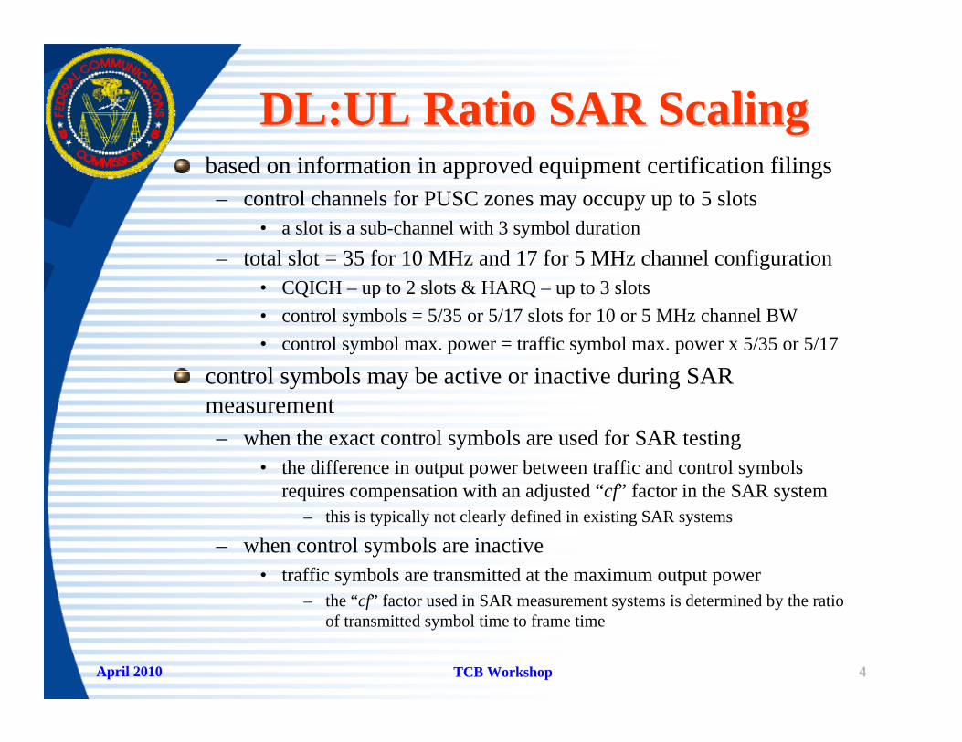
DL:UL Ratio SAR ScalingDL:UL Ratio SAR Scalingbased on information in approved equipment certification filings– control channels for PUSC zones may occupy up to 5 slots
• a slot is a sub-channel with 3 symbol duration– total slot = 35 for 10 MHz and 17 for 5 MHz channel configuration
• CQICH – up to 2 slots & HARQ – up to 3 slots• control symbols = 5/35 or 5/17 slots for 10 or 5 MHz channel BW• control symbol max. power = traffic symbol max. power x 5/35 or 5/17
control symbols may be active or inactive during SAR measurement– when the exact control symbols are used for SAR testing
• the difference in output power between traffic and control symbols requires compensation with an adjusted “cf” factor in the SAR system
– this is typically not clearly defined in existing SAR systems
– when control symbols are inactive• traffic symbols are transmitted at the maximum output power
– the “cf” factor used in SAR measurement systems is determined by the ratio of transmitted symbol time to frame time
April 2010 TCB Workshop 55
Scaling Factor ExampleScaling Factor Example
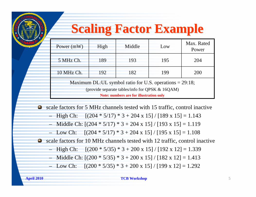
scale factors for 5 MHz channels tested with 15 traffic, control inactive– High Ch: [(204 * 5/17) * 3 + 204 x 15] / [189 x 15] = 1.143– Middle Ch: [(204 * 5/17) * 3 + 204 x 15] / [193 x 15] = 1.119– Low Ch: [(204 * 5/17) * 3 + 204 x 15] / [195 x 15] = 1.108
scale factors for 10 MHz channels tested with 12 traffic, control inactive– High Ch: [(200 * 5/35) * 3 + 200 x 15] / [192 x 12] = 1.339– Middle Ch: [(200 * 5/35) * 3 + 200 x 15] / [182 x 12] = 1.413– Low Ch: [(200 * 5/35) * 3 + 200 x 15] / [199 x 12] = 1.292
20019918219210 MHz Ch.
195
Low
Maximum DL:UL symbol ratio for U.S. operations = 29:18; (provide separate tables/info for QPSK & 16QAM)
Note: numbers are for illustration only
2041931895 MHz Ch.
Max. Rated PowerMiddleHighPower (mW)

April 2010 TCB Workshop 66
SAR Scaling ExampleSAR Scaling Example
1.401.551.54scaled SAR
10 MHz1.081.101.15Measured
SAR
1.2921.4131.339scale factor
SAR scaled to DL:UL symbol ratio of 29:18“cf” = 1/(15/48) = 3.2 for 5 MHz and 1/(12/48) = 4.0 for 10 MHz
Note: number of traffic symbols and other numbers are for illustration only; follow KDB procedures
1.501.581.43scaled SAR
1.351.411.25Measured SAR
1.1081.1191.143scale factor
5 MHz
LowMiddle HighChannelSAR (W/kg)

April 2010 TCB Workshop 77
Measurement LinearityMeasurement Linearitythe probe calibration procedures in SAR measurement standards are based on CW signals– duty factor scaling is applied “cf” factor for periodic signals – duty factor correction for non-periodic signals is not feasible
for high peak-to-average power ratio signals, such as OFDM– SAR error varies with the measured SAR level (i.e. device output
power) for probes using CW calibration– signal specific probe calibrations could be considered
• however, details & procedures are unavailable in SAR standards
for measurements in the square-law region of probe sensors– the measured SAR is low and SAR linearity errors are insignificant
for measurements outside of the square-law region of probe sensors– the error varies with signal characteristics and power/SAR levels– an estimate of the error margin is necessary to support test results

April 2010 TCB Workshop 88
SAR Linearity ExampleSAR Linearity Example
1.81.260.720.360.180.09linear line10 MHz
Note: numbers are for illustration only; need separate plots for channel BW & modulations
5 MHz
SAR (W/kg)
2.111.440.830.420.210.09point SAR
2.41.680.960.480.240.12linear line
2.71.801.030.520.260.12point SAR
20014080402010Power (mW)
April 2010 TCB Workshop 99
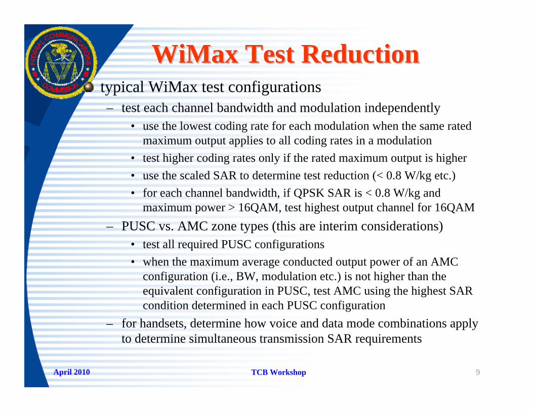
WiMax Test ReductionWiMax Test Reductiontypical WiMax test configurations– test each channel bandwidth and modulation independently
• use the lowest coding rate for each modulation when the same rated maximum output applies to all coding rates in a modulation
• test higher coding rates only if the rated maximum output is higher• use the scaled SAR to determine test reduction (< 0.8 W/kg etc.)• for each channel bandwidth, if QPSK SAR is < 0.8 W/kg and
maximum power > 16QAM, test highest output channel for 16QAM– PUSC vs. AMC zone types (this are interim considerations)
• test all required PUSC configurations• when the maximum average conducted output power of an AMC
configuration (i.e., BW, modulation etc.) is not higher than theequivalent configuration in PUSC, test AMC using the highest SARcondition determined in each PUSC configuration
– for handsets, determine how voice and data mode combinations apply to determine simultaneous transmission SAR requirements
April 2010 TCB Workshop 1010
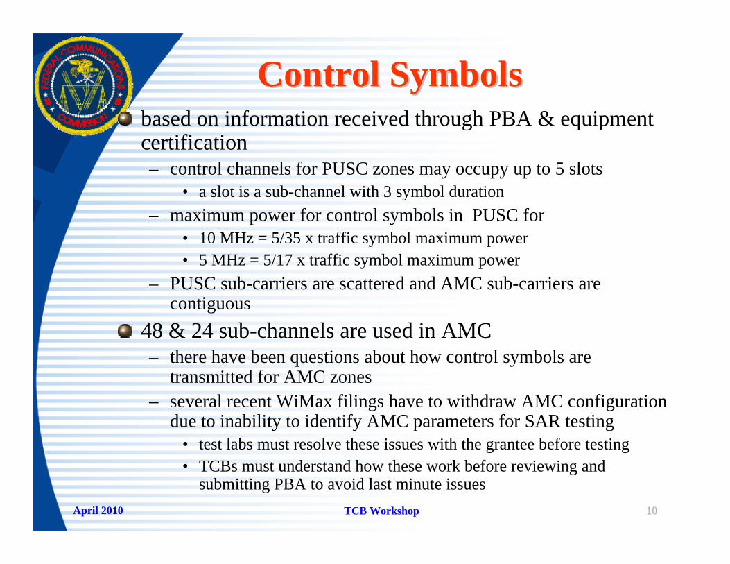
Control SymbolsControl Symbolsbased on information received through PBA & equipment certification– control channels for PUSC zones may occupy up to 5 slots
• a slot is a sub-channel with 3 symbol duration– maximum power for control symbols in PUSC for
• 10 MHz = 5/35 x traffic symbol maximum power• 5 MHz = 5/17 x traffic symbol maximum power
– PUSC sub-carriers are scattered and AMC sub-carriers are contiguous
48 & 24 sub-channels are used in AMC– there have been questions about how control symbols are
transmitted for AMC zones– several recent WiMax filings have to withdraw AMC configuration
due to inability to identify AMC parameters for SAR testing• test labs must resolve these issues with the grantee before testing• TCBs must understand how these work before reviewing and
submitting PBA to avoid last minute issues
ee--ReadersReaders
transmission duty factortransmission duty factorSAR test exclusionSAR test exclusionSAR measurementSAR measurement
accessory considerationsaccessory considerations
April 2010 TCB Workshop 1212
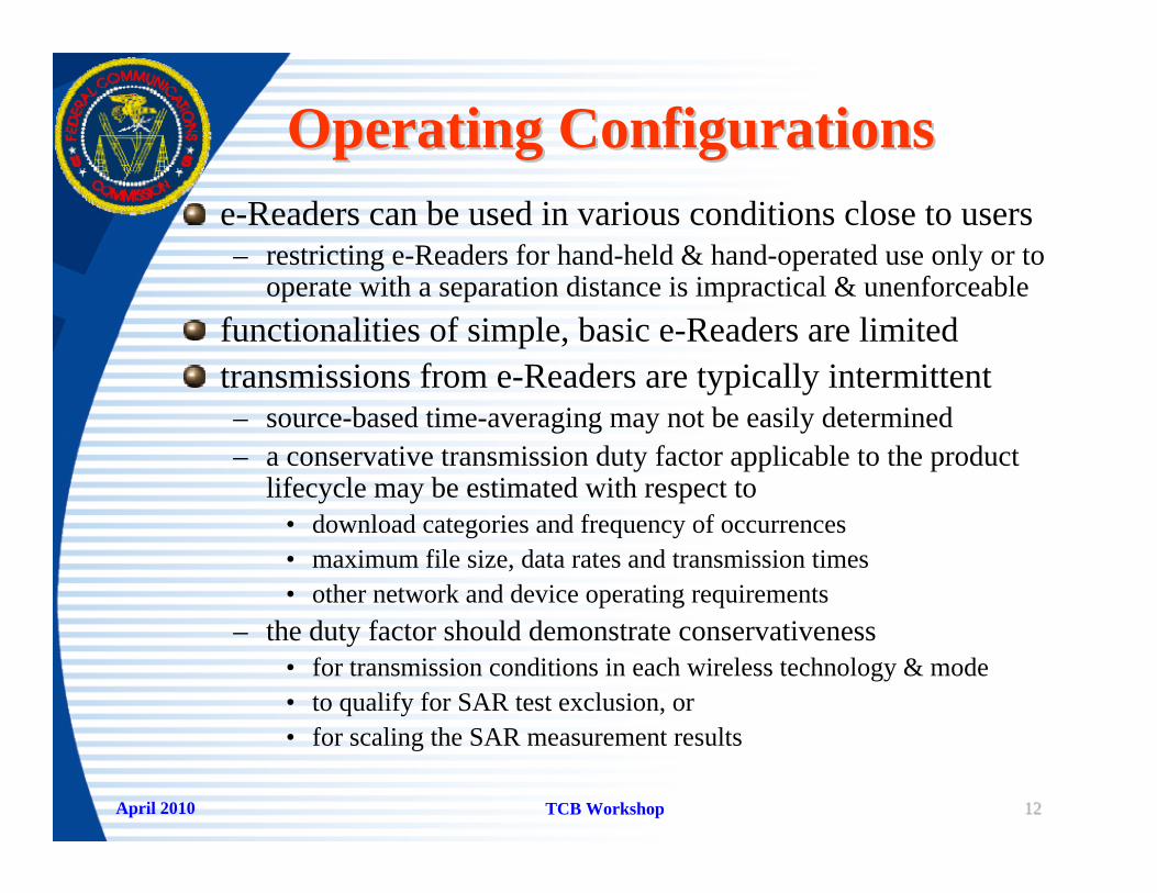
Operating ConfigurationsOperating Configurationse-Readers can be used in various conditions close to users– restricting e-Readers for hand-held & hand-operated use only or to
operate with a separation distance is impractical & unenforceablefunctionalities of simple, basic e-Readers are limitedtransmissions from e-Readers are typically intermittent– source-based time-averaging may not be easily determined– a conservative transmission duty factor applicable to the product
lifecycle may be estimated with respect to• download categories and frequency of occurrences• maximum file size, data rates and transmission times• other network and device operating requirements
– the duty factor should demonstrate conservativeness• for transmission conditions in each wireless technology & mode• to qualify for SAR test exclusion, or• for scaling the SAR measurement results
April 2010 TCB Workshop 1313
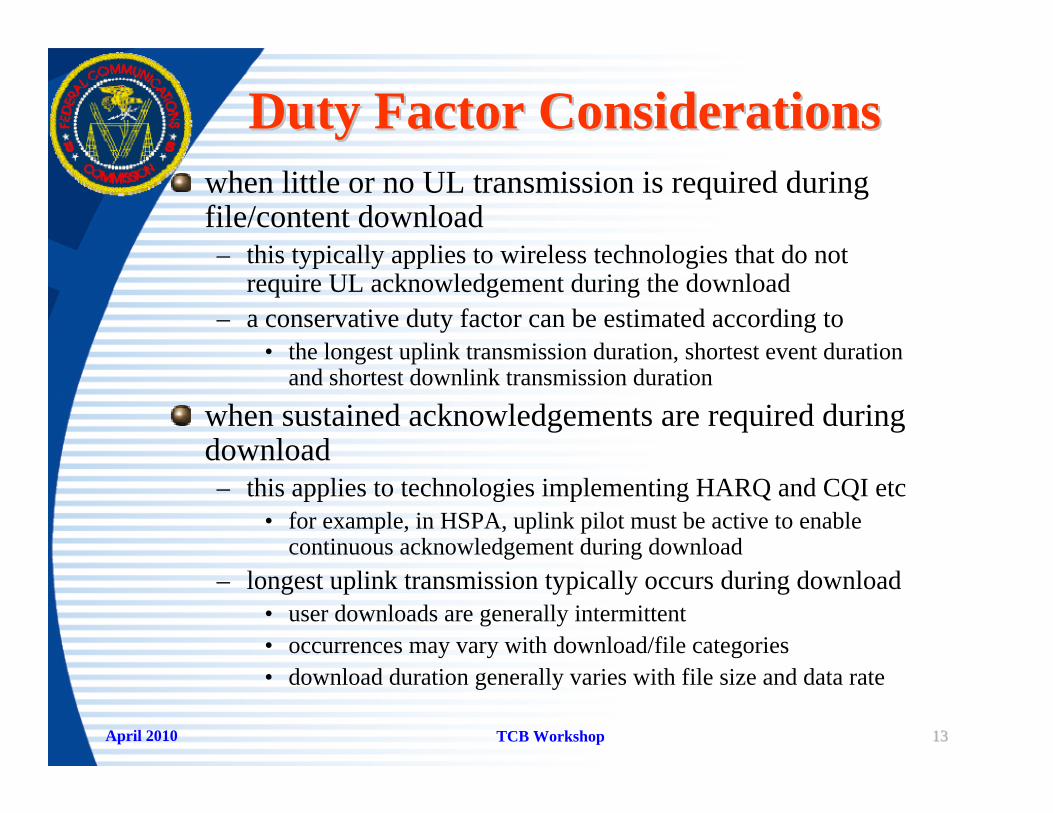
Duty Factor ConsiderationsDuty Factor Considerationswhen little or no UL transmission is required during file/content download– this typically applies to wireless technologies that do not
require UL acknowledgement during the download– a conservative duty factor can be estimated according to
• the longest uplink transmission duration, shortest event duration and shortest downlink transmission duration
when sustained acknowledgements are required during download– this applies to technologies implementing HARQ and CQI etc
• for example, in HSPA, uplink pilot must be active to enable continuous acknowledgement during download
– longest uplink transmission typically occurs during download• user downloads are generally intermittent• occurrences may vary with download/file categories• download duration generally varies with file size and data rate

April 2010 TCB Workshop 1414
Duty Factor CriteriaDuty Factor Criterialower data rate normally requires longer transmission time– however, uplink and downlink may allow different data rates
when uplink acknowledgement transmissions are required; for example, HSDPA/HSPA– larger download file size results in longer transmission time– frequency of occurrences for each download file size and
download type/category vary with available e-Reader services– the goal is to consider a conservative composite duty factor
other factors also need consideration– network acquisition and registration (transmission) time– minimum turnaround time for various events & transactions– determining the aggregate transmission time according to a
conservative transaction cycle and sequence of events
April 2010 TCB Workshop 1515
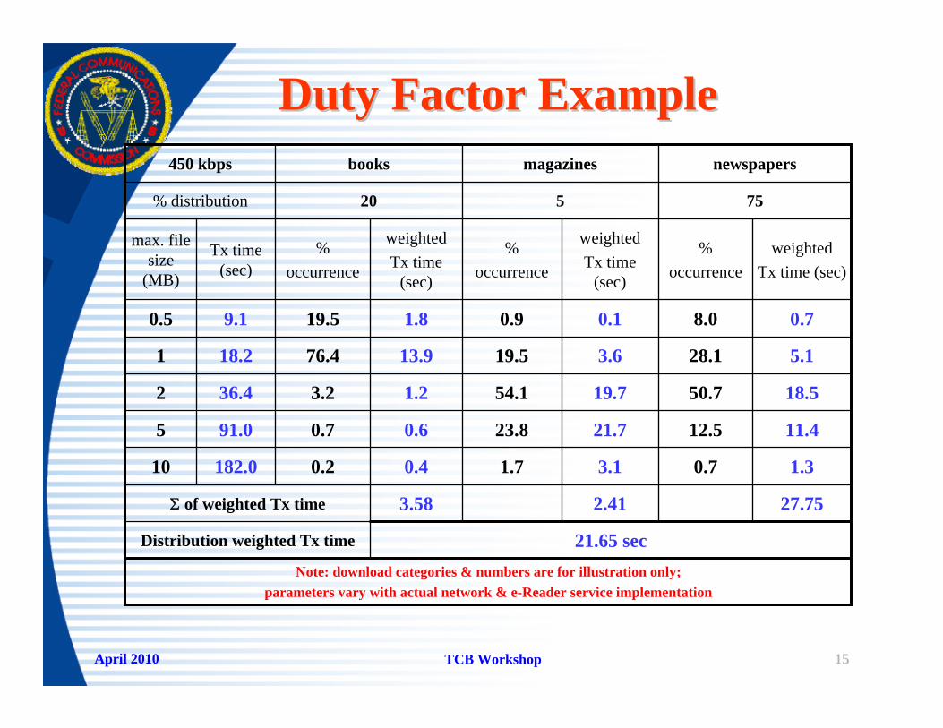
Duty Factor ExampleDuty Factor Example
21.65 secDistribution weighted Tx time
27.752.413.58Σ of weighted Tx time
75520% distribution
newspapersmagazinesbooks450 kbps
Note: download categories & numbers are for illustration only; parameters vary with actual network & e-Reader service implementation
1.30.73.11.70.40.2182.010
11.412.521.723.80.60.791.05
18.550.719.754.11.23.236.42
5.128.13.619.513.976.418.21
0.78.00.10.91.819.59.10.5
weightedTx time (sec)
%occurrence
weightedTx time
(sec)
%occurrence
weightedTx time
(sec)
%occurrence
Tx time (sec)
max. file size
(MB)
April 2010 TCB Workshop 1616
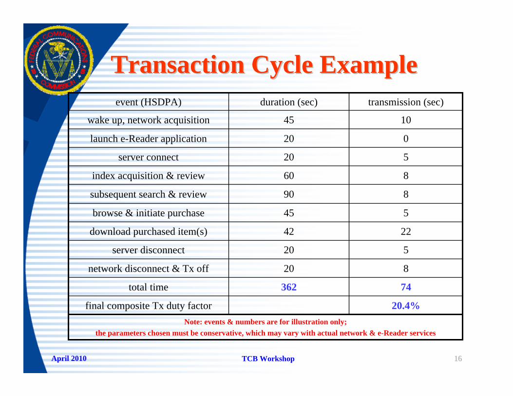
Transaction Cycle ExampleTransaction Cycle Example
20.4%final composite Tx duty factor
74362total time
Note: events & numbers are for illustration only;the parameters chosen must be conservative, which may vary with actual network & e-Reader services
820network disconnect & Tx off
520server disconnect
2242download purchased item(s)
545browse & initiate purchase
890subsequent search & review
860index acquisition & review
520server connect
020launch e-Reader application
1045wake up, network acquisition
transmission (sec)duration (sec)event (HSDPA)

April 2010 TCB Workshop 1717
SAR Test ConsiderationsSAR Test Considerationsa composite transmission duty factor is used to– determine SAR exclusion for each wireless mode
• according to the maximum average conducted output power scaled by this conservative transmission duty factor and 60/f(GHz) mW
– scale the SAR measurement results when evaluation is required
a separate analysis report is required to– detail the derivations and calculations used to establish
the composite transmission duty factor used for each wireless mode and technology
– demonstrate the conservativeness in applying the duty factors to support the expected operations of the product

April 2010 TCB Workshop 1818
Other eOther e--Reader ConsiderationsReader Considerationswhen SAR measurements are necessary– e-Readers should be tested according to the tablet procedures in
KDB 447498– an e-Reader cover may be considered during testing
• when it is permanently attached to the e-Reader, and• cannot be easily removed or discarded by the user
– testing with an arbitrary separation distance is unacceptable
when e-Reader functions are incorporated in other device platforms, such as computer tablet, PDA or cellphone– the test configurations and procedures required for the individual
platform must be used– if unclear, a KDB inquiry should be submitted to determine the test
requirements
Dual Transfer ModeDual Transfer Mode–– KDB 941225 KDB 941225 ––
applying the proceduresapplying the procedures

April 2010 TCB Workshop 2020
DTM ConfigurationsDTM ConfigurationsDTM applies to Class A GSM/(E)GPRS devices– provision for simultaneous transmission of both voice (CS)
and data (PS)– either with multiple transmitters or consecutive time-slots
according to DTM multislot class requirementsSAR test considerations– testing the device in DTM mode requires DTM
hardware/firmware support in a basestation testset– using independently tested voice & data SAR as an alternative
• to sum 1-g SAR according to each test position, or• to sum SAR distributions to compute 1-g SAR in each test
position– due to differences in phantom and test setup
• do not mix head and body exposure conditions when summing SAR to determine compliance for DTM mode
April 2010 TCB Workshop 2121
DTM DocumentationDTM DocumentationSAR report must include essential information to support the test configurations and results– GSM/(E)GPRS specifications
• GSM/(E)GPRS class• (E)GPRS multi-slot class• DTM multi-slot class
– maximum burst-average conducted output power may vary• for each operating mode – GMSK/8-PSK, & different slot modes• due to power reduction for specific mode & slot configurations
– description of procedures applied, device and equipment setup• is SAR measured in DTM mode or by summing separate data sets• power reduction in different wireless modes can introduce complex
combinations of test configurations and test reduction requirements in DTM
– clear explanations are required in the test report to support the results
Wireless ChargerWireless Charger–– KDB 680106 KDB 680106 ––
applying the proceduresapplying the procedures
April 2010 TCB Workshop 2323
Wireless Charging ApplicationsWireless Charging Applicationsdifferent design and implementation have been used– for wireless charging using inductive and radiating techniques– at various frequencies and power levels to provide coverage– to charge various consumer devices
RF exposure concerns often vary with implementation– due to frequency, power and operating characteristics
typical rule parts for approving wireless chargers– Part 18: allows higher power in allocated ISM bands
• requires RF energy to be generated and consumed locally• prohibits data transmission (communication)• RF exposure is categorically excluded but some design and
implementation may have issues– Part 15: field strength limits may restrict output power– Part 15 and Part 18 may both apply if there is control signal

April 2010 TCB Workshop 2424
Operating CharacteristicsOperating Characteristicspower requirements vary with frequency and coverage– inductive techniques are mostly used for designs in kHz range
• tightly coupled designs are more efficient, which may allow highoperating power with acceptable RF leakage and exposure; but coverage area for the charger could be limited
• flexible designs with moderate efficiency may charge multiple client devices simultaneously; but often with higher leakage and exposure
– radiating techniques are typically used for designs in MHz range• depending on power and installation requirements, potential for
exposure is generally higher
when multiple client devices are charged– leakage & exposure may vary because coupling efficiency could
change with different number and types of clientsthe inductive or radiating elements could be embedded in furniture, walls or ceiling– for localized or wide-area charging coverage implementations
April 2010 TCB Workshop 2525
RF Exposure ConsiderationsRF Exposure Considerationsfor the same wireless charging coverage, RF exposure is power, frequency, design and implementation dependent – higher power is typically needed for lower frequency operations– energy absorption in tissues is less efficient at lower frequencies
rules & limits for mobile and portable exposure conditions– SAR: 100 kHz – 6 GHz– MPE: 300 kHz – 100 GHz– §1.1307 (c) and (d) may apply
test equipment and evaluation procedure limitations– SAR procedures are intended for > 100 MHz, difficult < 30 MHz
• tissue dielectric parameters are undefined below 100 MHz for testing– numerical simulation at low frequency may have limitations– combinations of simulation, analytical analysis, field
measurements and other means may need to be considered
April 2010 TCB Workshop 2626
Client Devices ConsiderationsClient Devices Considerationsinfluence of clients to charging system– charging multiple and/or different client devices may
change the coupling efficiency of the charging system– this needs consideration to determine RF exposure
concerns for the charging systeminfluence of charging hardware in client devices may need additional RF exposure considerations– depending on the implementation of client devices
• versions with and without charging hardware may exist• SAR evaluation may be required for both versions
– when a client device can be used when it is being charged• depending on user proximity and charging system
implementation, simultaneous transmission exposure may need consideration
April 2010 TCB Workshop 2727
Equipment ApprovalEquipment Approvaldue to variability in design and implementation– information on individual charging implementation is
necessary to determine RF exposure evaluation requirements• frequency and power requirements• RF exposure concerns• availability of RF exposure test procedures and equipment
need KDB inquiry to determine– if RF exposure evaluation is necessary
• what procedures required to evaluate RF exposure compliance
– whether TCB approval is acceptable• if PBA is necessary
– how to coordinate ad-hoc test considerations and approval
LTELTE–– Interim Test Considerations Interim Test Considerations --
April 2010 TCB Workshop 2929
LTE ConsiderationsLTE Considerationshave received both KDB and other general inquiries about LTE, including questions about– how to test phones and modems with LTE– testing simultaneous transmission for LTE & other 3G modes
• for handsets using coordinated voice & data transmissions– how to apply the handset KDB procedures for LTE & 3G
KDB inquiries should include details about device characteristics and capabilities– UE category, power class, modulation, channel bandwidth,
frequency band, voice & data modes etc.test plan proposals should include– test equipment capabilities and requirements– device configuration and setup details– device and test setup limitations

April 2010 TCB Workshop 3030
LTE SAR ConfigurationsLTE SAR Configurationsdevice setup for SAR testing– have considered TS 36.101 Annex A.2.2, full RB allocation
RMC configurations for QPSK and 16QAM• need to ensure MPR and A-MPR are disabled and cannot be
triggered during SAR measurements– include details on how the device can be configured for
testing in RMC test operating modes using the test equipment (and test software/mode)
– include time and frequency domain plots to demonstrate the device is transmitting full RB allocation at its maximum average output power
if LTE transmits simultaneously with other modes– other information is needed to determine test requirements
• output power of various voice and data modes• how simultaneous transmission occurs• the operating configurations and exposure conditions
Dipole CalibrationDipole Calibration–– KDB 450824 KDB 450824 ––
applying the proceduresapplying the procedures

April 2010 TCB Workshop 3232
Extended CalibrationExtended Calibrationdipole calibration requirements– dipoles constructed according to parameters and tolerances
specified in IEEE 1528 do not require numerical validation• note: also see SAR target value issues for 5 GHz dipoles
– experimental validation is required for all dipoles before use• this requires a SAR system already validated with a calibrated
dipole; not an issue for system manufacturers• the new dipole cannot be calibrated with the same SAR system
that needs to be validated by the dipole; may not work for users
need supporting data to extend dipole calibration interval– need to include the measured SAR results, return-loss and
impedance data in SAR report or attached to dipole calibration report to demonstrate the dipole qualifies for extended calibration interval
– stating a dipole meets KDB 450824 requirements in the SAR report or dipole calibration report is insufficient

Laptop & NetbookLaptop & Netbook–– KDB 616217 Supplement KDB 616217 Supplement ––
applying the proceduresapplying the procedures
April 2010 TCB Workshop 3434
Test ConfigurationsTest Configurationsafter the 30-day draft review, an appendix was added to the final release of supplement to KDB 616217– to address various antenna orientations and associated test
configurations for supporting test conservativeness in intended laptop/netbook and tablet implementations
– allowing antennas to be integrated in various orientations and locations in laptops/netbooks without requiring additional certification
the earlier procedures in KDB 616217 will be phased out– to alleviate problems due to multiple Class II permissive changes
and other related issues for new product configurations– instead of gradually switching to the new procedures, manufacturers
have continued to use the earlier, problematic procedures– this does not facilitate transiting test requirements for new products

USB DongleUSB Dongle–– DongleDongle--Like Transmitters Like Transmitters ––
–– External Antennas External Antennas ––

April 2010 TCB Workshop 3636
DongleDongle--Like TransmittersLike Transmittersthe USB dongle procedures in KDB 447498 are intended for well defined dongle configurationsthe procedures may not apply to other dongle-like devices– oversized or irregular shaped dongle-like configurations– certain devices with a USB connection
• through a short cable or other adapter configurations• but using retractable or similar antenna configurations
– inquire before testing to ensure the test results are acceptable
for dongles with specific mechanisms, inquire before test– allowing power reduction in specific operating configurations– disabling transmission in specific conditions– built-in restrictions to limit device operating positions

April 2010 TCB Workshop 3737
External AntennasExternal Antennasmost USB dongles may have a service port– for conducted power measurement– typically not accessible to the end user or with unique connectors
when such ports are easily accessible to the end user– the reserved functionality of a service port should be clearly stated
in the manual instructions to avoid misuse
ports that are intended for external antenna connections– must have practical mechanisms to ensure a minimum separation
distance is available in the installation to qualify specific antenna(s) for use in mobile exposure conditions; otherwise,
– SAR evaluation may be necessary, with respect to the operating configurations and acceptable antenna mounting conditions
it is unacceptable and unenforceable to require users to maintain a minimum separation to maintain compliance

SAR Test ReductionSAR Test Reduction–– SAR level based KDB Provisions SAR level based KDB Provisions ––
April 2010 TCB Workshop 3939
Test Reduction ClarificationTest Reduction ClarificationKDB procedures and SAR measurement standards have allowed SAR test reduction based on measured SAR levels– the SAR level for test reduction is typically ~50% of the SAR limit– cellphone SAR measurement standards generally expect consistent
maximum outputs across channels, for earlier generation devices• test reduction has been based on the SAR for the middle channel
– devices using newer technologies and unlicensed transmitters often do not have similar maximum output consistency across channels
• KDB requires test reduction based on maximum output channel
when maximum output variation across channels is < ½ dB– either maximum output or middle channels may be used to
determine test reduction for each mode in a cellphone; otherwise,– use the maximum output channel to determine test reduction for all
other product and technology configurations, including cellphones

SAR Test ExclusionSAR Test Exclusion–– apply correct KDB procedures apply correct KDB procedures ––

April 2010 TCB Workshop 4141
SAR Exclusion ProceduresSAR Exclusion Proceduresdifferent SAR test exclusion criteria are provided in various KDB procedures– the procedures may be based on similar concepts and look similar– the requirements for applying the exclusion procedures can be
different due to host platform & other test configuration concerns– some devices may have the option to apply one of several SAR
test exclusions• the exclusion conditions must be clearly identified in the SAR report
to qualify for the exclusion; otherwise, test results are expected– certain exclusions may require specific justifications or other
prerequisite conditions, which must be clearly documented in theSAR report to qualify for the exclusion
• for example, different requirements in KDB 447498, KDB 616217 or KDB 648474 etc.
Test DeviceTest Device–– acceptable samples acceptable samples ––
April 2010 TCB Workshop 4343
Acceptable Test SamplesAcceptable Test Samplesa test device must be representative of the production units, with respect to §2.908; for example, within specified– production tolerance, electrical and mechanical tolerances– performance specifications etc
the measured maximum output power must be within– the specified tune-up tolerance range for production units
the test results must demonstrate compliance– for all applicable limits, including maximum output power, RF
exposure and various EMC requirements– when results are extrapolated to the upper tune-up tolerance limit,
with respect to the maximum measured output power of the test sample, to ensure all production units are compliant
– to alleviate potential inconsistencies in determining compliance

SAR StandardsSAR Standards–– outlook outlook ––
test methodologiestest methodologiesphantom and measurementphantom and measurement
draft standardsdraft standardswhat to usewhat to use
April 2010 TCB Workshop 4545
Test MethodologiesTest Methodologiesfaster SAR measurement and test reduction mechanisms are under consideration by SAR measurement standards committees– two categories of fast SAR methods have been proposed, those use
• existing SAR system hardware, but different measurement procedures and/or algorithms to reduce the measurement time
• different hardware and measurement procedures required by existing SAR measurement systems and standards
– various test reduction considerations have also been proposed, based on• device (cellphone) design and style• measured SAR levels, power and other parameters• test positions and phantom configurations etc
signal specific probe calibration have been under investigation– specific details and defined procedures are unavailable– the alternative is to measure SAR at low power
• within square-law region of the probe sensorsSAR measurement concerns for current generation technologies– Wi-Fi, 3G, WiMax, LTE etc. have not been addressed in existing drafts
• signal modulation and high peak-to-average power ratio issues etc.
April 2010 TCB Workshop 4646
PhantomsPhantomsrotated SAM phantom are available for measurement in jaw and mouth elliptical flat phantom has been introduced in IEC drafts & standardsinfluence of the hand on head SAR has been reported– 1528-2003 identified that hand holding cellphone has little influence on
head SAR; therefore, hand phantom is not required for head SAR testing– recent investigations reveal that hand holding a phone can introduce
substantial SAR increases for some phones; but the causes seem unclear– hand phantoms have become available and could be considered for testing
tissue dielectric parameters – head vs. body– there are on-going efforts to use a single set of tissue dielectric parameters
for both head and body SAR measurements; certain issues need resolution• selecting dielectric parameters for an expanded frequency of 30 MHz – 6 GHz• conservativeness of parameters at the low and high frequencies is unclear• conservativeness of parameters according to body anatomy seems unclear• SAR enhancement concerns due to tissue layers below 200 MHz need review

April 2010 TCB Workshop 4747
MeasurementsMeasurementssimultaneous transmission– volume scan procedures still inefficient– various test reduction considerations have been proposed
measurement uncertainty analysis in on-going drafts– the uncertainty procedures have become even more complex– many test labs are unable to apply existing procedures
• there is the need to seek alternative and much simpler solutionstissue dielectric parameter offset adjustment– procedures have been proposed in recent drafts– need to consider implementation logistics or user transparency
SAR scaling considerations have been proposed for– modulation, power, signal characteristics etc; but lack details
5 GHz dipole target values can vary– actual values may have larger deviations from expected target
April 2010 TCB Workshop 4848
Standards StatusStandards StatusIEEE Std. 1528-2003: 300 MHz – 3 GHz– provides basic SAR measurement system requirements– for testing 2.5G cellphone at the head only, next to the ear
IEC 62209-1 (2005) - similar to IEEE Std. 1528-2003IEC 62209-2 (2010): 30 MHz – 6 GHz– provides body SAR test position for some product configurations
• some concerns about tissue dielectric parameter conservativeness• simultaneous transmission & modular configurations insufficient
– allowing fast SAR, test reduction and other considerations• but lack detail procedures to implement reliable test protocol
IEC 62209-MT: expanding 62209-1 to cover 30 MHz – 6 GHz– also addressing some of the 62209-2 concerns
IEEE Std. 1528 revision (draft): 300 MHz – 6 GHz– mostly insufficient for testing current generation phones
wireless technology issues not address by all drafts & standards
April 2010 TCB Workshop 4949
Procedures to UseProcedures to Usethere are quite a few on-going proposals and changes in existing drafts and revised SAR measurement standardsmany of the useful proposals and procedures have already been adapted into existing KDB proceduresother additional procedures not addressed by on-going SAR measurement standards and drafts have also been considered and included in the KDB proceduresmany of the on-going or remaining proposals and procedures need additional details for implementation– test labs and TCBs should follow the required KDB procedures– after concerns are addressed, these other proposals and
procedures can be considered accordingly for equipment certification testing