revision 004-1/98 rm-11 operations manual operations manual 5 10.6 rm-tc transit container 47 figure...
TRANSCRIPT

RM-11 Operations Manual 1Revision 004-1/98

2 RM-11 Operations Manualii

RM-11 Operations Manual 3i
iii
Contents
1.0 Product Information .................................................... 61.1 Design Features ................................................................................................... 7
2.0 Configurations Available ........................................... 102.1 RM-11 Models .................................................................................................... 10
Figure 2.1 RM-11 Metronic Primary Watthour Standard ................................... 10
3.0 Specifications .......................................................... 113.1 Accuracy ..................................................................................... 113.2 Input ................................................................................................................... 113.3 Output ................................................................................................................. 113.4 Normal Operating Conditions ............................................................................. 123.5 Influences Affecting Accuracy ............................................................................ 123.6 Protection ........................................................................................................... 123.7 Burden Values .................................................................................................... 123.8 Physical Description ........................................................................................... 13
Figure 3.8 RM-11 Physical Dimensions ............................................................ 13
4.0 Operations Overview ................................................ 144.1 Auxiliary Power ................................................................................................... 144.2 Current Input ...................................................................................................... 14
Table 4.2 Current Autoranging Points ................................................................ 154.3 Potential Input ..................................................................................................... 15
Table 4.3 Potential Autoranging Points .............................................................. 154.4 Remote Reset Switch Input ................................................................................ 164.5 Percent Registration Calculation ........................................................................ 174.6 Pulse Output ....................................................................................................... 17
Table 4.6 Pulse Frequency Table (pulses per second) ...................................... 194.7 Closed Link Testing ............................................................................................. 19
5.0 Theory of Operation ................................................. 205.1 Input Potential Circuit ......................................................................................... 205.2 Input Current Circuit ........................................................................................... 205.3 Auxiliary Power Supply ....................................................................................... 215.4 Watt Converter ................................................................................................... 215.5 Current To Frequency Converter ........................................................................ 225.6 Range Control Circuit ......................................................................................... 22

4 RM-11 Operations Manual
Contents
5.7 Digital Display/Output Circuit .............................................................................. 23Figure 5.7 RM-11 Block Diagram ...................................................................... 24
6.0 Service & Routing Maintenance ................................ 256.1 Fuse Replacement ............................................................................................. 256.2 Cleaning ............................................................................................................. 266.3 Repair ................................................................................................................. 266.4 Case Removal .................................................................................................... 266.5 Recalibration ...................................................................................................... 27
7.0 Recalibration ........................................................... 28Figure 7.0a Typical Radian Calibration Report .................................................. 29Figure 7.0b Digital Switch Location ................................................................... 30Table 7.0c Typical Recalibration Sheet .............................................................. 32
8.0 VARhour/Qhour Models ............................................. 338.1 Potential Gating .................................................................................................. 338.2 Stability ............................................................................................................... 338.3 Function Select ................................................................................................... 348.4 I/O Control / Communications Port .................................................................... 34
Figure 8.4a I / O Port Pin Description ............................................................... 35Figure 8.4b Drive Options .................................................................................. 35Figure 8.4c Mode Select Options ...................................................................... 36Figure 8.4d Display Control Options ................................................................. 37
9.0 200 Amp Models ...................................................... 38Figure 9.0 Paralleling the Three Current Inputs ................................................ 38
10.0 Test Accessories ....................................................... 3910.1 RM-110 Automated Comparator ........................................................................ 39
Figure 10.1 RM-110 Automated Comparator ..................................................... 4110.2 RM-1S Remote Reset Switch ............................................................................ 41
Figure 10.2 RM-1S Remote Reset Switch ........................................................ 4110.3 RM-1A Photo Counter Interface ......................................................................... 42
Figure 10.3 RM-1A Photo Counter Interface ..................................................... 4310.4 RM-1D Frequency Divider .................................................................................. 43
Figure 10.4 RM-1D Frequency Divider ............................................................. 4510.5 RM-1P Electronic Light Valve ............................................................................. 45
Figure 10.5 RM-1P Electronic Light Valve ......................................................... 46
iv

RM-11 Operations Manual 5
10.6 RM-TC Transit Container .................................................................................... 47Figure 10.6 RM-TC Transit Container Features ................................................ 47
11.0 Testing Applications .................................................. 4811.1 Testing a Radian Standard ................................................................................. 48
Figure 11.1 Testing a Radian Standard ............................................................. 5211.2 Testing a Radian Standard using the Averaging of Three Inputs ....................... 53
Figure 11.2 Testing a Radian Standard using the Averaging of Three Inputs ... 5711.3 Testing an Electromechanical Standard (potential gating) ................................. 58
Figure 11.3 Testing an Electromechanical Standard (potential gating) ............. 6011.4 Testing an Electronic Standard (potential gating) ............................................... 61
Figure 11.4 Testing an Solid State Standard (potential gating) ......................... 6311.5 Testing an Electronic Standard (electronic gating) ............................................. 64
Figure 11.5 Testing an Solid State Standard (electronic gating) ....................... 6611.6 Testing the Accuracy of a Test Board (RM-1P Electronic Light Valve Option) .... 67
Figure 11.6 Testing the Accuracy of a Test Board(RM-1P Electronic Light Valve Option) ............................................................... 68
11.7 Testing the Accuracy of a Test Board (Open Collector Option) .......................... 69Figure 11.7 Testing the Accuracy of a Test Board (Open Collector Option) ...... 70
Pulse constants and Kh values for use withthe RM-110 ....................................................................... 71
13.0 Warranty & Calibration Service ...................................... 72
v
Contents
12.0

6 RM-11 Operations Manual
1.0 Product IntroductionThe RM-11 Metronic Primary Watthour Standard is by far the most accurateself-contained primary watthour standard manufactured in the United States,with typical accuracies in the 0.003% range and repeatabilities in the0.001% range. It is essentially an enhanced version of the RM-10 PortableWatthour Standard, optimized for accuracy and stability and retaining thesame lightweight, package for portability and economy. By retaining 70% ofthe same circuitry, which is mass produced, the RM-11 easily outperformsprimary standards costing three to six times as much. It represents the pres-ent state of the art in electronic watthour reference standards with a conser-vative accuracy specification of 0.025% worst case for one year. Stabilityis included within this maximum accuracy specification. Also, the accuracyapplies to all operating points between 0.2 and 50 amperes and 60 to 600VAC. Autoranging potential and current inputs coupled with an inherent ex-tremely wide operating range permit these specifications. The Radian RM-703 automated calibration system tests the RM-11 standards automaticallyon overnight runs, including temperature testing. A total of 300 calibrationpoints are taken at final test with over a thousand points taken during pretestand subassembly testing.
The RM-11 utilizes the following accuracy enhancing design techniques:
• Supermalloy cores are used simultaneously with the electronically com-pensated cores from the RM-10 design. This reduces transformer errors toapproximately the 0.0005 to 0.0001 percent level (one to five parts per mil-lion).
• Burned in references are selected for stability and checked for drift forthree months prior to incorporation within the RM-11. At this point in time,the drift histories of the references selected must assure that stability is morethan sufficient to meet drift specifications.
• An ultra low noise power supply reduces errors at low levels. The RM-11operates only at 120 to 240 VAC and is therefore not directly interchange-able with the RM-10 for field use. The circuitry to permit potential gating isabsent as well, for higher accuracy.
Product Introduction

RM-11 Operations Manual 7
• Fifteen ranges in the autoranging circuit are used to reduce low level er-rors by 50%.
These changes reduce typical errors from the 0.015% level to the 0.003%level at room temperature and reduce typical errors from the .035% level tothe .012% level over temperature compared to the RM-10.
The RM-11 has no potentiometers whatsoever so the need of hand carryingstandards to and from NIST for the best accuracy is totally eliminated. Threeunits within 0.001% of each other when shipped by UPS have been ob-served to be within 0.001% of each other upon arrival.
1.1 Design Features
The RM-11 Metronic Watthour Standard is a true second generation elec-tronic watthour standard. It represents a new standard of performance inprimary watthour standards, completely surpassing the previous generationof electronic watthour standards in all areas of performance. Novel featuresinclude very superior accuracy of 0.003% typical and 0.025% maximum, aswell as very superior time and temperature stability. Other features pio-neered by Radian include transparent automatic range changing on potentialand current inputs, true display in watthours on all ranges (Kh of 1) and sub-stantially greater resolution. The superior performance and many advancedfeatures eliminates the need to use calibration correction factors. A simplesix function memory calculator converts watthours to percent registration ina single simple calculation.
Four revolutionary features utilizing novel and innovative design are prima-rily responsible for the superior performance of the RM-11:
• Transparent automatic current range changing makes the RM-11watthour standard unequalled in ease-of-use in actual laboratory operations.The input has sufficient internal ranges to measure all currents from 0.2 am-peres to 50 amperes with full rated worst case accuracy of 0.025%. Thecorrect and optimum range is found by the instrument after current is appliedand before the measurement is started. The output to the digital display andto the pulse output are also ranged simultaneously so as to retain calibrationin watthours regardless of the range selected.
Product Introduction

8 RM-11 Operations Manual
“Transparent” means there is no external or visible effect to the rangechanging except enhanced accuracy. The output pulse rate, digital display,etc. are unaffected. The automatic range changing also gives complete pro-tection from failures due to application of high currents to the wrong range.
• Transparent automatic voltage range changing performs exactly thesame functions on the voltage axis and also protects the standard from fail-ure due to operator error.
• An ultra high resolution output is capable of supplying an output fre-quency of up to 1000 times that of older models and with improved accuracyas well. This permits full rated accuracy at test times of 3.6 seconds.
In addition to these revolutionary features, a number of other advanced fea-tures solve the problems which have kept older designs from attaining theirstated 0.1% accuracies in most realistic field situations:
• All toroidal input transformers provide superior immunity to stray fields.Close physical proximity to load boxes or to a high current bus is permittedwithout derating accuracy. The small influences are included in the basicaccuracy specifications.
• Electronic transformer compensation eliminates almost all transformererror. This alone eliminates 75% of the error present in older designs andeliminates the need for using correction factors. This feature permits a con-servative 0.025% accuracy at 0.5 power factor worst case.
• 100% hermetic, burned-in internal references are a first for a primarydevice. The reference set is also the theoretical minimum number of refer-ences required for a watthour instrument, also a first for a primary device.Together, these have permitted the achievement of typical stabilities below0.005% per year in drift. With such low drifts, the RM-11 is specified tomeet 0.025% worst case accuracy for a period of one full year after recali-bration.
• An advanced Pulse Width Modulation (PWM) multiplier is used. PWMis still among the best approaches to watthour measurement and has the ad-vantage of known and few limitations in standards use. The most seriouslimitations, high errors on the popular voltage gating test approach and
Product Introduction

RM-11 Operations Manual 9
subharmonic beat frequency errors, have been substantially reduced in theadvanced design of the RM-11.
• Warmup drift has been dramatically reduced by the elimination of elec-trolytic capacitors from the measurement signal path, by the use of signifi-cantly improved hermetic internal references and by the use of an aluminumenclosure to substantially reduce internal heating. The RM-11 will deliverfull rated performance within 15 minutes of power on.
•The elimination of potentiometers permits the full rated performance ofthe RM-11 to be retained in the presence of the severe handling, shock andvibration. There are no potentiometer wipers to be knocked out of calibra-tion. The calibration is accomplished by digital decade switches with a totaladjustment range of +.099 to -.099%. Shock or vibration short of damagingor catastrophic levels will not have a measurable influence on the perform-ance of the RM-11. The reference elements are shock mounted to preventsevere shocks from influencing them.
• Remote digital gating of the register with the remote switch or digitalinput eliminates the need for switching of the potential input and the associ-ated errors. The remote switch works on a three cycle control. In the resetcondition the display reads zeros and does not count. A push of the switch(or a digital input) enables the display and watthours will register. A secondpush freezes the display and a value other than zero will be visible to indi-cate this state. A third push will reset the display to zero ready for anothermeasurement with no need to push the reset button adjacent to live and haz-ardous terminals.
• Summing current inputs permit closed link testing on all types of watthourmeters. For normal testing, any one of the three current inputs may be used.The sum of all three currents is limited to 150 amperes, with a 50 amperelimit per input. For closed link testing, three isolated current sources arerequired in place of the usual one current source.
Product Introduction

10 RM-11 Operations Manual
2.0 Configurations Available
2.1 RM-11 Models
RM-11-01 Primary Watthour StandardRM-11-02 Primary Watthour 200 Amp StandardRM-11-03 Primary Watthour Standard with I/O Communications PortRM-11-06 Primary Watthour/VARhour StandardRM-11-07 Primary Watthour/VARhour/Qhour StandardRM-11-08 Primary Watthour/VARhour/200 Amp StandardRM-11-09 Primary Watthour/VARhour/Qhour/200 Amp Standard•The RM-11-02, -03, -06, -07, -08 and -09 are provided with an I/O Communications Port
Configurations Available
Figure 2.1 RM-11 Metronic Primary Watthour Standard
O
POTENTIAL
POWERAUXILIARY
O OO CURRENT CURRENTCURRENT
B CA
RADIAN RESEARCH INC.LAFAYETTE, INDIANA 47905
WATT HOUR
VAC120-240
Hz59-61
VAC60-600
Wh(0.05% VAR/Q)0.025%
AMPERES0.2-50.0
Wh/PULSE0.00001
86541

RM-11 Operations Manual 11
Specifications
3.0 Specifications
3.1 Accuracy
All errors are in percent of reading at any combination of the normal operatingconditions. Note that stability is included within the maximum accuracy specificationsfor Watthours, VARhours and Qhours. *Power factor is referenced to Watthours andit is also assumed that voltage is the reference vector.
WatthourAt Unity Power Factor* (0°): ±0.003% typical, ±0.025% maximumAt 0.5 Lag Power Factor* (-60°): ±0.007% typical, ±0.025% maximumAt Power Factor* P< 0.5
(f between -60° and -90°): ±0.025%/P maximum
VARhourAt 0.0 Lag Power Factor* (-90°): ±0.05% typical, ±0.1% maximumAt 0.866 Lag Power Factor* (-30°): ±0.05% typical, ±0.1% maximum
QhourAt Unity Power Factor* (0°): ±0.05% typical, ±0.1% maximumAt 0.5 Lag Power Factor* (-60°): ±0.05% typical, ±0.1% maximum
3.2 Input
Input Terminal: BNC, digital display gate
3.3 Output
Output Terminal: BNC
Pulse Value: Watthour 0.00001Watthour 0.00002 (200 Amp Version)
The percent of nominal VARhour and Qhour output can be calculated by using thefollowing formulas:
*(pf of 1.0 to 0.0 lag)
% OUTPUT pf pfQhour = + × − ×. ( ) *5 3 1 1002
% OUTPUT pfVARhour = − ×1 1002

12 RM-11 Operations Manual
3.4 Normal Operating Conditions
Input Voltage: 60 to 600 VAC (Autoranging)Input Current: 0.2 to 50.0 Amperes (Autoranging)
150 Amps maximum when paralleling 3 inputsPower Factor: Any (see accuracy definition)Ambient Temperature: 20° to 30° C (68° to 86° F)Relative Humidity: 0 to 95 %Auxiliary Power Voltage: 120 to 240 VAC (Autoranging)Frequency: 59 to 61 Hz or 48 to 52 Hz
For Varhour and Qhour correction atother frequencies refer to page 37.
Orientation: AnyRecalibration Interval: 365 daysWarm-up: 15 minutesShock and Vibration: Any which is nondestructive
3.5 Influences Affecting Accuracy
Temperature: ±0.0003%/°C typical, ±0.001%/°C maximum (Watthours)-20° to 70° C (-4° to 158° F)
±0.001%/°C typical, ±0.005%/°C maximum (VARhour/Qhour only)-20° to 70° C (-4° to 158° F)
3.6 Protection
Isolation: Complete: Inputs/Output/Power/Case/ControlDielectric Withstand: 2.3 kVrms, 60 Hz, 60 secondsSurge Withstand: IEEE 472 and ANSI 37.90Fuses: Schurter #0342516 or Radian #3001000
3.7 Burden Values
Potential Input: Impedance InputVoltage Burden (V2/R)
10 pF 120 V 0.0001 VA240 V 0.0003 VA480 V 0.001 VA600 V 0.002 VA
Specifications

RM-11 Operations Manual 13
Specifications
Current Input: Impedance Input Burden(I2R) Burden(I2R/3)Current single input 3 inputs in parallel
0.001ohm. 0.2 A 0.00004 VA 0.000013 VA0.5 A 0.00025 VA 0.00008 VA5 A 0.025 VA 0.008 VA50 A 2.5 VA 0.8 VA150 A DO NOT USE 7.5 VA
Auxiliary Power: 3.5 W for RM-114.0 W for multifunction RM-11<10 VA for all units
3.8 Physical Description
Size: 190.5 mm (7.5") High excluding rubber feet139.7 mm (5.5") Wide139.7 mm (5.5") Deep excluding latches and strap
Weight: 2.5 kg (5.5 lbs); 3.6 kg (8 lbs) shipping weight
Shipping Dimensions: 305 mm (12") High248 mm (9.75") Wide248 mm (9.75") Deep
Display: 12.7 mm (0.5") LCD, 6 digitsReadout in Watthours, VARhours, Qhours
RM-11 STANDARDFigure 3.8 RM-11 Physical Dimensions

14 RM-11 Operations Manual
4.0 Operations Overview
4.1 Auxiliary Power
Auxiliary Power is required to power the electronic watt converter, currentto frequency converter, display and transformers. Auxiliary power must besupplied independent from the potential input source. The voltage can rangefrom 120 to 240 VAC at any frequency from 48 to 500 Hz. Because of anabsence of ranges to be selected, either manually or automatically, it is veryunlikely that a fuse will ever be blown. Fuse replacement may be required ifthe display fails to indicate. Press the panel reset once if the display is notlit, then verify a.c. power on the auxiliary power terminals with a voltmeter.If power is present, consult Section 5 for fuse replacement instructions. Thefuses are mounted underneath the connection terminals and are accessibleexternally.
For laboratory and OEM use (incorporated within test panels), the RM-11auxiliary power is best connected to any convenient a.c. source which isindependent of the potential signal. The source used may be any voltage be-tween 120 and 240 VAC. For optimum performance use a twisted pair notrun in the same bundle as the current leads.
4.2 Current Input
The RM-11 has three separate and isolated current inputs. All are identicaland interchangeable, and may be paralleled for lower burden (rarely neces-sary) or put in series to increase sensitivity. This configuration facilitateseasy and accurate closed link testing (Section 4.7) when used with testboards and load boxes with multiple floating current outputs. For most exist-ing applications connect the current leads to any one of the current inputsand ignore the other two current inputs. Leave the unused current inputsfloating (open). NEVER short an unused current input on any type of wat-thour standard.
The current input of the RM-11 is autoranging and covers the entire rangefrom 0.2 amperes to 50 amperes in five ranges on only a single input and to150 amperes with the three inputs in parallel. The five ranges keep the watt
Operations Overview

RM-11 Operations Manual 15
converter of the RM-11 close enough to full scale so that full rated accuracyis obtained over this 750:1 range. The display is also ranged such that thedisplay always registers in watthours. Hysteresis is provided at the rangingthreshold points. The unit is designed for the input current to be set prior tothe start of a test to preclude ranging during the course of a test. Tests per-formed with load boxes or in test panels are performed in this way. Smalladditional errors will occur on unstable loads, but this additional error istypically less than 0.002% for each range change within a 30 second test.Following are the ranging points for the current axis:
4.3 Potential Input
The potential input of the RM-11 is entirely autoranging from a range of 60to 600 VAC. Following are the ranging points for the potential axis:
The potential input is totally autoranging so there is no need to manually se-lect a voltage range. Since both the potential and auxiliary power do notrequire an operator selection of range, the usual fuse replacement and reli-ability problems associated with this function are eliminated. Both of theseinputs are fused with the fuses being underneath the input terminals. Refer toSection 6.1 for replacement.
Phasing must be observed when connecting the potential. If the phasing iswrong, reverse power flow will not be indicated and the instrument will notregister. If no energy is registering, check the phasing and also verify with avoltmeter and a clamp-on type ammeter that the signals are actually present.
Operations Overview
CURRENT AUTORANGINGRange 1 Range 2 Range 3 Range 4 Range 5
Increasing Current 0 - 0.432A 0.433 - 1.731A 1.732 - 6.925A 6.926 - 27.7A 27.71 - 50A
Decreasing Current 0.356 - 0A 1.425 - 0.357A 5.7 - 1.462A 22.80 - 5.701A 50 - 22.81A
Table 4.2 Current Autoranging Points
POTENTIAL AUTORANGINGRange 1 Range 2 Range 3
Increasing Voltage 0 - 152V 153 - 263V 264 - 600V
Decreasing Voltage 129 - 0V 248 - 130V 600 - 249V
Table 4.3 Potential Autoranging Points

16 RM-11 Operations Manual
4.4 Remote Reset Switch Input
The INPUT connector on the RM-11 is for connection of a control input togate the display on and off and to reset it. This input connection replacesboth the reset switch and the click switch or photocounter control whichgates the potential input. Gating the register rather than the potential input isdefinitely more accurate on any standard since the measurement circuitrythen gets a flying start on the measurement. Potential gating has only beendone historically because of lack of alternatives.
The most common input is the Radian RM-1S Remote Reset Switch. It con-nects directly to the INPUT connection of the RM-11 by means of a BNCshielded connector. A momentary push of the button starts the counter. Asecond push stops it after the test duration (frequently 10 revolutions), freez-ing the last reading for as long as desired and a third push will reset thecounters to zero for the next test.
The INPUT will also accept a normally closed contact or normally on tran-sistor open collector from any source. The common of the INPUT is fullyisolated from the internal common of the standard to eliminate noise or hipotproblems. A momentary pulse (open) lasting between .05 and one secondwill trigger the input. The display circuit will sense the leading edge of thecontact open. The INPUT control has no effect on the pulse output.
4.5 Percent Registration Calculation
The output of the RM-11 is used to calculate the percent registration of theUnit Under Test. The formula by which this is accomplished is much simplerthan the conventional calculation. The output of the RM-11 reads out inwatthours, with a Kh of 1.00 on all ranges. The RM-11 is also accurateenough and linear enough that there is little necessity in using correction fac-tors for the standard. Hence, the simple calculation of percent registration.The formula to be used is:
Operations Overview

RM-11 Operations Manual 17
where “%REG” is the percent registration, “Kh” is the watthour constant ofthe Unit Under Test,“ REV” is the number of revolutions of the test, “DIS-PLAY” is the displayed value in watthours and “EL” is the number of ele-ments energized with the same current on the meter under test.
For two and one half element meters (two elements, three current leads forfour wire circuits), use the value of four for the “EL” in the above calcula-tions.
For one and one half element meters (residential Form 2S meters) a factor ofone is used for a standard test and 0.5 elements for a closed link (two cur-rent elements on the RM-11) test.
4.6 Pulse Output
The pulse output is available on the RM-11 display panel as a BNCshielded connector labeled OUTPUT. The extreme resolution of the RM-11 yields an output with a calibration of 10 microwatthours per pulse(0.00001 watthours per pulse or 100,000 pulses per watthour). This calibra-tion is the same on all voltage and current ranges.
Table 4.6 lists the pulse frequencies which are obtained at typical operatingvoltages and currents. All the values are reduced by 50% at 0.5 power fac-tor. All values are multiplied by the number of current inputs used (EL).
The output frequency may be calculated at any voltage, current and powerfactor by the following formula:
where 3600 is the number of seconds in an hour and 0.00001 is the numberof watthours per pulse.
Operations Overview
%REG=100xKhxREV
(DISPLAYxEL)
PF
(3600x0,00001)FREQ=ELxVOLTSxAMPSx

18 RM-11 Operations Manual
To reach the maximum frequency out when designing an interface to a com-mercial counter or systems interface to the RM-11, a pull-up resistor of1000 ohms or less is recommended so that the capacitance of the connectingcables can be overcome without losing counts. If a cable run of more thansix feet is necessary, lower the pull-up resistor value accordingly. The RM-11 can sink a maximum of 50 milliamperes, permitting a pull-up resistorlimitation of 100 ohms minimum at five volts. If the available power supplycannot supply the current for low resistor values, consider using low ca-pacitance cable for long runs. For test board interface development work,there is no substitute for a close inspection of the output waveform at maxi-mum frequencies with an oscilloscope to verify that there are absolutely noproblems with pulses being missed.
The frequencies which are obtained, ranging from 666.7 to 666.667 Kilo-hertz in Table 4.6, are beyond the input capabilities of some calibrationequipment. A variable divide down device makes interface with the oldercalibration equipment straightforward. The RM-1D Frequency Divideravailable from Radian Research can solve this problem (see Section 10.4).
A typical laboratory configuration using multiple primary standards is de-tailed in Section 11.2 Testing a Radian Standard using the Averaging ofThree Inputs. The output pulses from three primary standards are fed into theinput ports of the RM-110 Automated Comparator. The RM-110 is used toaverage or sum the input pulses and control the device under test. This con-figuration can be used to calibrate field standards and meter calibration testtables. In addition, the RM-11 and RM-110, when used with the appropriateaccessories, can be used to calibrate both solid state and induction meters.Refer to Section 11 Testing Applications for more information.
Operations Overview

RM-11 Operations Manual 19
Operations Overview
@1.0 pf 120v 240v 480v0.20a 666.7 1333.3 2666.70.25a 833.3 1666.7 3333.30.50a 1666.7 3333.3 6666.71.00a 3333.3 6666.7 13333.32.00a 6666.7 13333.3 26666.72.50a 8333.3 16666.7 33333.35.00a 16666.7 33333.3 66666.7
10.00a 33333.3 66666.7 133333.315.00a 50000.0 100000.0 200000.020.00a 66666.7 133333.3 266666.725.00a 83333.3 166666.7 333333.345.00a 150000.0 300000.0 600000.050.00a 166666.7 333333.3 666666.7
4.7 Closed Link Testing
Three sets of input terminals are provided for the purpose of closed linktesting. The input transformer of the RM-11 has three identical input wind-ings, arbitrarily labeled A, B and C. Each of these is put in series with aseparate floating current source. Because the current sources and the sepa-rate inputs of the RM-11 are isolated from each other, there is no need toopen the potential link or make a connection to the opened link. The advan-tages to this extend beyond the necessity of using meters without links todiscourage power diversion.
The current sources cannot be wound on a common core because the loadsbeing driven are not nearly identical enough. Two or three separate coresare necessary to create the high impedance current sources to make this tech-nique work.
Table 4.6 Pulse Frequency Table (pulses per second)

20 RM-11 Operations Manual
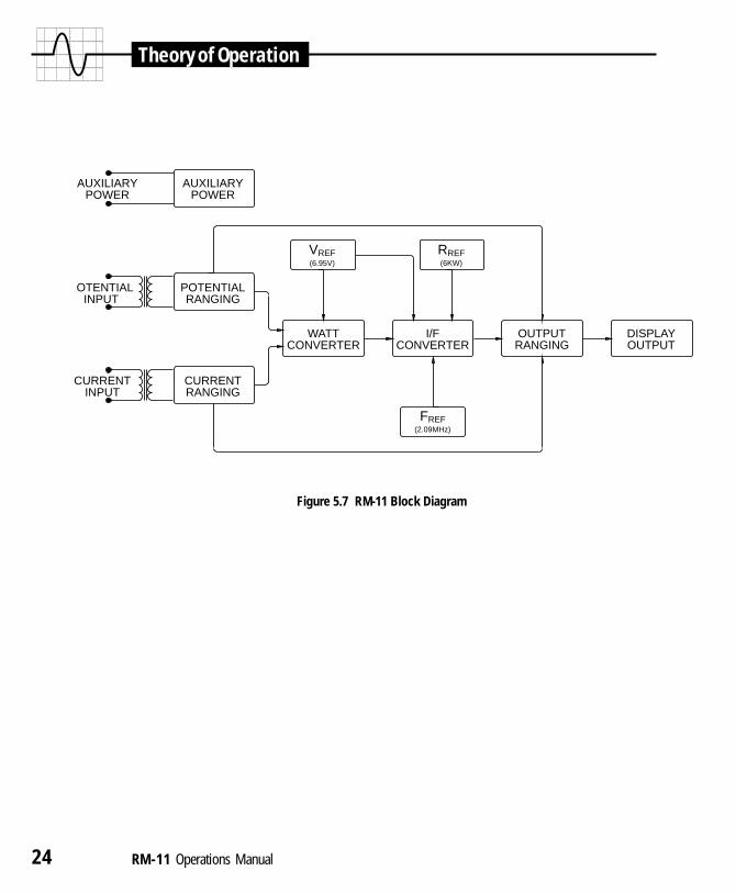
5.0 Theory of OperationThe RM-11 Metronic Primary Watthour Standard consists of seven basicblocks as illustrated in Figure 5.7. These include an input potential circuit,an input current circuit, an auxiliary power supply, a watt converter, a cur-rent to frequency converter (watthour converter), a range control circuit anda digital display/output circuit.
5.1 Input Potential Circuit
The Input Potential Circuit senses potential input voltages in the range ofzero to 630 VAC, with full rated accuracy in the range of 60 to 600 VAC.The circuit consists of a toroid wound potential transformer with electronicmeans of sensing and removing over 99% of the error. The transformer is soaccurate that it is not a significant source of error regardless of the inputlevel. The range selection is accomplished on the secondary side, with muchgreater accuracy and reliability than can be achieved with primary sideswitching. Operator error does not enter into the range selection which isautomatic. Typical accuracy is 0.001% on all three ranges without calibra-tion, selection of components or trimming of any kind. Unlike resistive in-puts, there is no hipot problem (5KV typical breakdown), no adjustment isrequired, and the temperature drift, time instability and warmup drift are allimmeasurable (less than 0.0001%).
5.2 Input Current Circuit
The Input Current Circuit accepts a current in the range of 0.2 to 50 amperes(150 amperes total) and isolates, ranges and scales the current to maintainan input current to the watt converter in the range of 1 to 5 milliamperes.The construction is of the toroidal type so that there is no problem with strayfields. Electronic compensation reduces errors to below our measurementthreshold (0.0001%) at most operating currents, and to below 0.001% overthe entire specified region. With this low error it is feasible to do all tapchanging on the secondary side at essentially dry circuit levels, thereby get-ting about 100 times the life expectancy of primary side switching. The inputburden is also drastically reduced with about 0.02 VA at five amperes. Two
Theory of Operation

RM-11 Operations Manual 21
additional current inputs are provided for closed link testing in conjunctionwith three isolated current sources.
5.3 Auxiliary Power Supply
The Auxiliary Power Supply is able to operate efficiently at any voltagebetween 120 and 240 VAC. No relay contacts or range changing is requiredto accomplish this so reliability is excellent. The auxiliary power supply hasan overall efficiency of 70% which changes very little with input voltage.This high efficiency results in a very low power consumption of about 3.5watts which, in conjunction with an aluminum case, results in a very lowinternal temperature rise. This, coupled with a typical temperature coeffi-cient below 0.0003% per degree C, results in negligible warmup drift. VAconsumption varies between 5 and 9 VA depending on the input voltage.
5.4 Watt Converter
The Watt Converter is of the pulse width modulation type. A pulse widthmodulation multiplier forms a product by producing a pulse train the heightof which is proportional to one input and the width of which (duty cycle) isproportional to a second input. A filter performs an integration, producingan average value proportional to the area under the pulses, which is propor-tional to the product of the two inputs.
An often overlooked aspect of using pulse width modulation for power con-version is that the current axis (load dependent) is much more likely to bedistorted than the potential axis (line dependent). In pulse width modulationthe axis which determines pulse height (the multiplexor axis) is much lesssensitive to distortion. In the RM-11 this is the axis which senses the currentinput to minimize distortion sensitivity. Standards designed with the axesreversed will work fine on the calibration bench (low distortion) but maynot work satisfactorily for customer load testing.
The watt converter has a voltage and a current input (units of watts) and hasa current output. Since input:output is watts:current which is equivalent tovolts, a voltage reference is required to reference the watt converter. No
Theory of Operation

22 RM-11 Operations Manual
other component within the watt converter has a significant effect upon thecalibration.
5.5 Current To Frequency Converter
The Current to Frequency Converter (watthour circuit) converts the currentoutput of the Watt Converter into a pulse train with each pulse proportionalto watthours of energy. It is referenced by a highly advanced charge balanceintegrator which can produce a much higher frequency (two megahertz or 7billion pulses per hour) than older converters limited to pulse rates of only400 hertz or 1.5 million pulses per hour. The circuit delivers this degree ofresolution without compromise of the accuracy, which is typically 0.003%.The high resolution is of advantage in field testing because it permits theautoranging on the current axis which in turn will ultimately permit closedlink testing.
The current to frequency integrator works on the charge balance principle.The input current is proportional to watts. The input current over a period oftime is proportional to watthours. The units of current times time is charge,so that the charge accumulated in a capacitor over a period of time is di-rectly proportional to watthours. Quanta of charge are removed from thecapacitor after they have accumulated for a fixed period of time. Eachquanta of charge which is removed is directly proportional to ten microwat-thours. The removal of charge is accomplished by injecting a current ofknown amplitude and known duration. The amplitude of the current is deter-mined by the ratio of an extremely precise voltage reference to an extremelyprecise resistor. The duration of the pulse is determined by one clock cycleof a 2.09 megahertz crystal.
5.6 Range Control Circuit
The Range Control Circuit accepts the pulse train from the current to fre-quency converter and scales the signal according to the range it has selectedfor the potential and current input transformers. The range selected is theoptimum range for accuracy for the two signals sensed. The scaled fre-quency coming from the range control circuit has a direct calibration of tenmicrowatthours on all current and voltage ranges. The output frequency at
Theory of Operation
RM-11 Operations Manual 23
100 amperes and 600 VAC is 1.6666666 megahertz and the output frequencyat 0.1 amperes and 120 volts is a modest 333.333 Hertz. The energy perpulse value remains the same over the entire range.
5.7 Digital Display/Output Circuit
The Digital Display/Output Circuit accepts the pulse train from the RangeControl Circuit and counts it. The counter is controlled by the Input connec-tion to the RM-11. A pulse at this input resets the counter and the display tozero. A second pulse starts the counter. A third pulse stops the counter andfreezes the display until a further pulse starts the process over again. TheDisplay Circuit also has a simulation mode: it detects the absence of a sig-nal source at the input and simulates the operation of competitive products.In this mode the counter runs continuously in the presence of a watthour inputsignal and is reset to zero by a panel reset switch.
The Digital Display/Output Circuit also creates an isolated open (transistor)collector pulse output. This Output is optically coupled for high isolationand low noise. The calibration of the output signal is identical to the cali-bration of one count to the display which is ten microwatthours/pulse.
The Digital Display/Output Circuit display section displays six digits of aten digit counter. When the count is less than 9.99999 watthours, the decimalpoint is placed as X.XXXXX to show all available resolution. When thecount exceeds that number the decimal point shifts one number to the right.With this system it is possible to supply a large, easy to read liquid crystaldisplay and still display all of the resolution when fairly low count numbersare being observed. The display will continue to advance and display accu-rately until it reaches 9999.99 watthours.
Theory of Operation
24 RM-11 Operations Manual
Theory of Operation
Figure 5.7 RM-11 Block Diagram
AUXILIARYPOWER
AUXILIARYPOWER
OTENTIALINPUT
CURRENTINPUT
POTENTIALRANGING
CURRENTRANGING
VREF(6.95V)
RREF(6KW)
WATTCONVERTER
I/FCONVERTER
OUTPUTRANGING
DISPLAYOUTPUT
FREF(2.09MHz)

RM-11 Operations Manual 25
6.0 Service & Routing MaintenanceThe RM-11 Metronic Primary Watthour Standard is virtually maintenancefree. The use of a highly advanced all hermetic referencing system reducesdrift an order of magnitude and therefore permits yearly recalibrations withno degradation in performance. The elimination of all contacts, switches andtap selections on the primary side of the input transformers significantly im-proves reliability by eliminating both service components and the opportu-nity for operator error. Other than cleaning of the outside surface and theyearly recalibration, no routine maintenance is required.
6.1 Fuse Replacement
Fuse replacement is not very likely because of the elimination of primaryside switching. However, fuses are included and are accessible without dis-assembly. There are four fuses: two potential input and two auxiliary power.Fuse replacement is performed as follows:
1. Test for blown fuses. Approximately 14 to 17 Kohms of impedance on thepotential input circuit is normal; approximately .08 amperes of current drawis normal at 120 VAC of the auxiliary power.
2. Replace both fuses on a circuit if one is bad.
3. Remove the terminal knobs of the circuit with bad fuses.
4. Remove the stainless steel set screws underneath each of the two terminalswith a 1/8 inch Allen (hex key) wrench.
5. Remove the fuses underneath by turning the RM-11 upside down and shak-ing the fuses out.
6. Replace the fuses with 5 x 20 mm 1 ampere medium blow fuses. Schurter#0342516 or Radian #3001000 are recommended. If the unit blows the fusesagain, the unit needs to be serviced.
Service & Routine Maintenance

26 RM-11 Operations Manual
6.2 Cleaning
Cleaning of the RM-11 may be performed with a clean, dry lint-free clothdampened slightly with a mild window cleaner. The areas around the topterminals should be buffed dry with another cloth which is completely cleanand totally dry. This is to maintain dielectric with complete assurance forvoltages of 480 volts and higher.
6.3 Repair
Repair is recommended to be performed by Radian Research. We have ex-cellent automated testers with which every internal module can be testedquickly to original factory specifications. A final calibration and qualitycontrol inspection to original factory specifications is performed quicklyand thoroughly.
6.4 Case Removal
Removal of the case is required to obtain access to the digital decadeswitches to set calibration. Since the unit is readily subject to damage whenout of the case, it is recommended that the change in calibration be deter-mined prior to case removal. For instance, suppose that it is determined thatthe unit is running 0.007% slow and that the records show that the presentsetting of the calibration is +0.034%. The new number must be 0.007%higher to correct for the slow output. The RM-11 can therefore be removedfrom the case and the switches changed to +0.041.
To remove the case first ease the leather strap off of the strap retainers. Sec-ondly, remove the retainers by inserting a 3/64" Allen (hex key) wrenchthrough the hole and carefully remove the strap retainer so as not to damagethe paint. The RM-11 can then be slid carefully out of the case by pulling onthe lip of the black thermoplastic top panel (DO NOT use a screwdriver topry the RM-11 from the case). After recalibration reassemble in the reverseorder being careful to replace the internal insulating paper. The internal in-sulating paper is best wrapped around the RM-11 and then slid into the casewith it. The internal paint can withstand the rated hipot voltage but the insu-lating paper provides insurance against a breakdown due to scratches.
Service & Routine Maintenance

RM-11 Operations Manual 27
6.5 Recalibration
Recalibration is recommended yearly. Section 7 details the procedure ofrecalibrating the RM-11. A periodic cross check against another RM-11 isrecommended to preclude the possibility of a failure in either.
Service & Routine Maintenance

28 RM-11 Operations Manual
Recalibration
7.0 RecalibrationRecalibration is recommended at yearly net intervals. We highly recommendthe use of Radian’s recalibration service as a very cost effective alternativeto manual recalibration by the utility. Our RS-703A Syntron AutomatedCalibration System has a repeatability of better than 0.001% and an accu-racy limited by available calibration from the National Institute of Standardsand Technology. Our RS-703A Syntron Automated Calibration System col-lects a data point on a Radian standard every fifteen seconds on up to six-teen standards simultaneously, collecting literally thousands of data pointson an overnight run. When using this service, and economics permit, pru-dence would dictate having a dedicated RM-10 or an RM-11 primary stan-dard which is checked by NIST or NRC (National Research Council inCanada). With this instrument it is feasible to sample test units at variouspoints as a “backup” test.
Historically, watthour standards have had to run at each power setting forconsiderable periods of time to be calibrated. This has been due to two in-teracting effects within the input transformers. The high burden of first gen-eration electronic watthour standards causes heating in the inputtransformers. The accuracy of the transformers and stability of the electron-ics renders a sensitivity to this heating which must stabilize out for data tobe taken. The RM-11 has such low input burden that this heating is verysmall. The electronically compensated transformers and advanced refer-ences of the RM-11 are highly immune to heating even if it were not small.Our extremely accurate and cost effective automated recalibration systempermits highly accurate data points to be taken within a few seconds of eachother (See Figure 7.0a).

RM-11 Operations Manual 29
Figure 7.0a Typical Radian Calibration Report
Recalibration
C A L IB R A T IO N R E P O R T
R M - 1 1 - 0 6 M E T R O N IC P R IM A R Y W A T T H O U R S T A N D A R D
M O D E .............................. W A T T H O U R S
D A T E ................................ 2 0 - J a n -9 8
S E R IA L N U M B E R ......... 5 0 1 2 0 4
T H E F O L L O W IN G D A T A W A S C O L L E C T E D B Y A N R S -7 00 3A S YN T R O N A U T O M A T E D C A L IB R A T IO NS YS T E M . T T H E R S - 70 3 A C A L IB R A T IO N S YS T E M IN C O R P O R A T E S A N R M - 1 1 P R IM A R Y R E F E R E N C ES T A N D A R D C A L IB R A T E D B Y T H E N A T IO N A L IN S T IT U T E O F S T A N D A R D S A N D T E C H N O L O G Y T OA N U N C E R T A IN T Y O F 0 .00 5 % A T U N IT Y P O W E R F A C T O R A N D 0 .0 10 % A T 0 .5 P O W E R F A C T O R .T H E T E S T P A R A M E T E R S W E R E 2 3 D E G R E E S C E N T IG R A D E W IT H H A T E S T TM E O F 1 5 S E C O N D SP E R P O IN T . T H E T IM IN G W A S D O N E B Y G A T IN G T H E P U L S E O U T P U T . F O R L A GGI N G P O W E RF A C T O R S , T H E C U R R E N T L A G G E D T H E V O L T A G E .
V O L T A G E & P H A S E A N G L E
1 2 0 1 2 0 2 4 0 2 4 0 4 8 0 4 8 0 6 0 0 6 0 0U N IT Y 6 0 ' LA G U N IT Y 6 0 ' LA G U N IT Y 6 0 ' LA G U N IT Y 6 0 ' LA G
A M P S0 .5 0 .0 02 0 .0 00 0 .0 00 0 .0 03 0 .0 01 0 .0 03 0 .0 01 0 .0 061 .0 0 .0 00 0 .0 01 -0 .0 0 2 0 .0 03 -0 .0 0 2 0 .0 04 -0 .0 0 1 0 .0 062 .0 -0 .0 0 2 -0 .0 0 2 -0 .0 0 3 0 .0 00 -0 .0 0 3 0 .0 02 -0 .0 0 2 0 .0 042 .5 -0 .0 0 1 -0 .0 0 2 -0 .0 0 4 0 .0 01 -0 .0 0 4 0 .0 02 -0 .0 0 2 0 .0 053 .0 -0 .0 0 3 -0 .0 0 2 -0 .0 0 3 0 .0 00 -0 .0 0 4 0 .0 02 -0 .0 0 2 0 .0 055 .0 0 .0 00 0 .0 00 -0 .0 0 1 0 .0 01 -0 .0 0 2 0 .0 04 0 .0 01 0 .0 066 .0 0 .0 00 0 .0 00 -0 .0 0 2 0 .0 02 -0 .0 0 2 0 .0 04 -0 .0 0 1 0 .0 06
1 0 .0 -0 .0 0 1 -0 .0 0 3 -0 .0 0 1 0 .0 02 -0 .0 0 1 0 .0 02 -0 .0 0 1 0 .0 051 2 .0 0 .0 00 -0 .0 0 1 -0 .0 0 1 0 .0 01 -0 .0 0 1 0 .0 04 0 .0 00 0 .0 061 5 .0 0 .0 00 0 .0 01 -0 .0 0 2 0 .0 02 -0 .0 0 2 0 .0 03 0 .0 01 0 .0 062 0 .0 0 .0 01 0 .0 01 -0 .0 0 1 0 .0 02 -0 .0 0 2 0 .0 05 0 .0 00 0 .0 072 5 .0 0 .0 00 -0 .0 0 1 -0 .0 0 1 0 .0 03 -0 .0 0 1 0 .0 05 0 .0 01 0 .0 063 0 .0 0 .0 00 0 .0 00 -0 .0 0 1 0 .0 02 -0 .0 0 1 0 .0 05 0 .0 00 0 .0 064 0 .0 0 .0 01 0 .0 01 -0 .0 0 1 0 .0 02 -0 .0 0 2 0 .0 05 0 .0 00 0 .0 074 5 .0 0 .0 01 0 .0 01 -0 .0 0 1 0 .0 04 -0 .0 0 2 0 .0 05 0 .0 01 0 .0 075 0 .0 0 .0 01 0 .0 01 -0 .0 0 2 0 .0 02 -0 .0 0 2 0 .0 05 0 .0 00 0 .0 07
A V E R A G E 0 .0 0 0 0 .0 0 0 - 0 .0 0 2 0 .0 0 2 - 0 .0 0 2 0 .0 0 4 0 .0 0 0 0 .0 0 6
M A XIM U M 0 .0 02 0 .0 01 0 .0 00 0 .0 04 0 .0 01 0 .0 05 0 .0 01 0 .0 07M IN IM U M -0 .0 0 3 -0 .0 0 3 -0 .0 0 4 0 .0 00 -0 .0 0 4 0 .0 02 -0 .0 0 2 0 .0 04
O V E R A L LU N IT Y 6 0 ' LA G
A V E R A G E -0 .0 0 1 0 .0 03M A XIM U M 0 .0 02 0 .0 07M IN IM U M -0 .0 0 4 -0 .0 0 3
THE FOLLOWING DATA WAS COLLECTED BY AN RS-703A SYNTRON AUTOMATED CALIBRATIONSYSTEM. THE RS-703A CALIBRATION SYSTEM INCORPORATES AN RM-11 PRIMARY REFERENCESTANDARD CALIBRATED BY THE NATIONAL INSTITUTE OF STANDARDS AND TECHNOLOGY TO ANUNCERTAINTY OF 0.005% AT UNITY POWER FACTOR AND 0.010% AT 0.5 POWER FACTOR. THE TESTPARAMETERS WERE 23 DEGREES CENTIGRADE WITH A TEST TIME OF 15 SECONDS PER POINT. THETIMING WAS DONE BY GATING THE PULSE OUTPUT. FOR LAGGING POWER FACTORS, THECURRENT LAGGED THE VOLTAGE.

30 RM-11 Operations Manual
The watthour calibration of the RM-11 is changed by the setting of two ten-position digital switches located on the bottom printed circuit board of thestandard. The switches have 199 possible settings between +0.099 and -0.099%. As referenced to Figure 7.0b, Switch 1 changes the second calibra-tion digit to the right of the decimal point and Switch 2 changes the thirdcalibration digit to the right of the decimal point. Switch 3 changes the regis-tration from negative (left position) to positive (right position). To adjust to100.000% registration, mathematically subtract the percent error of the stan-dard from the number derived by reading the three switches. To illustrate theprocess of recalibrating a Radian standard using the digital switches, thefollowing four examples are given:
SW 1
SW 2
.010%
.001%
SW 3
Figure 7.0b Digital Switch Location
Recalibration

RM-11 Operations Manual 31
1. Initial switch settings are SW1=3, SW2=2 and SW3=right (+0.032) andthe percent error of the standard is –0.005%. Therefore, the standard isrunning at 99.995% registration or 0.005% slow. To adjust to 100.000%registration the new switch settings would be SW1=3, SW2=7 andSW3=right (+0.037). [+0.032 – (–0.005) = +0.037]
2. Initial switch settings are SW1=3, SW2=2 and SW3=right (+0.032) andthe percent error of the standard is +0.005%. Therefore, the standard isrunning at 100.005% registration or 0.005% fast. To adjust to 100.000%registration the new switch settings would be SW1=2, SW2=7 andSW3=right (+0.027). [+0.032 – (+0.005) = +0.027]
3. Initial switch settings are SW1=1, SW2=8 and SW3=left (–0.018%) andthe percent error of the standard is –0.007%. Therefore, the standard isrunning at 99.993% registration or 0.007% slow. To adjust to 100.000%registration the new switch settings would be SW1=1, SW2=1 andSW3=left (+0.011). [–0.018 – (–0.007) = –0.011]
4. Initial switch settings are SW1=0, SW2=1 and SW3=right (+0.001%)and the percent error of the standard is +0.004%. Therefore, the stan-dard is running at 100.004% registration or 0.004% fast. To adjust to100.000% registration the new switch settings would be SW1=0,SW2=3 and SW3=left (–0.003). [+0.001 – (+0.004) = –0.003]
Historically, calibration factors have been used instead of adjusting stan-dards. The primary intent was to maintain a calibration history. Units withsubstantial drift could be detected by virtue of a continuously changing cali-bration factor with time. The problem with readjustment was that potenti-ometers and other screw adjustments became more unstable mechanicallyafter adjustment than before. The digital decade switches of the RM-11 can-not be bumped or jarred from their setting in transportation or handling andthe switches themselves provide the calibration history. The switch settingsshould definitely be recorded with the date at the time of each recalibration.A typical sheet may look as follows:
Recalibration

32 RM-11 Operations Manual
Table 7.0c Typical Recalibration Sheet
A recalibration is normally performed at 120 VAC, 5 amperes and unitypower factor. A reason for checking for power factor error and for error oneach range is to check against the very remote possibility of a failure whichmay have occurred which is not apparent at the reference point.
To verify full accuracy on every internal range it is sufficient to check theRM-11 approximately every factor of two on current and voltage: 0.1, 0.2,0.5, 1, 2, 5, 10, 20 and 50 ampere checks as well as 80, 120, 240 and 480volt checks will assure that all ranges are properly functioning. The RM-11should be within 0.025% at all unity power factor points and at all 0.5power factor points.
Gang testing is the most economical method of calibration verification onRM-11 Standards. A number of standards are powered with auxiliary powerin parallel, potential inputs in parallel and currents in series (unused cur-rents inputs are open of course). The “Input” connections on the RM-11 reg-isters are paralleled using one RM-1G cable per RM-11 so that one RM-1SRemote Switch controls all RM-11 Standards. Optionally, an RM-110 Auto-mated Comparator may be used in place of the RM-1S. If testing other typesof standards along with RM-11 Standards then the RM-110 Automated Com-parator is necessary.
Recalibration
Date Setting Notes
3/06/94 +.032 NEW UNIT, AS RECEIVED
6/06/94 +.037 THREE MONTH CHECK OF NEW UNIT
3/06/95 +.039 ROUTINE YEARLY RECALIBRATION
3/09/96 +.039 ROUTINE YEARLY RECALIBRATION
3/06/97 +.039 ROUTINE YEARLY RECALIBRATION

RM-11 Operations Manual 33
VARhour / Qhour Models
8.0 VARhour / Qhour Models
8.1 Potential Gating
Potential gating, a time honored approach which today should be avoidedbecause of more accurate approaches, is fundamentally incompatible withthe VARhour or Qhour function. All Radian standards are designed for gat-ing of the register rather than the potential, thus making a VARhour or Qhourstandard practical. The Radian RM-1A Photocounter Interface is recom-mended to eliminate the need for potential gating for applications where thehardware or procedures already exist; such as with older test board designs.
8.2 Stability
The stability of the VARhour and Qhour function of the RM-11 is signifi-cantly improved over that of older VARhour circuits. The stability is im-proved by eliminating electrolytic capacitors from the signal path and byusing all hermetically sealed reference components. The capacitors used arethe most stable type film capacitors known. 90 day recalibration and avoid-ance of temperature excursions beyond 10 to 40 degrees Celsius are recom-mended to attain the highest possible stability. Recalibration should beperformed at 120 Volts, 5 Amperes and 100% output. The phase error of theVARhour or Qhour circuit is small enough that it never needs to be cali-brated.
Stability of the VARhour or Qhour function is enhanced considerably byavoiding temperature extremes. There is a hysteresis of about 0.02% by go-ing from temperature extremes for long periods (greater than 12 hours) andthen returning to room temperature. The hysteresis set can be elimi-nated by temperature cycling (-20, +70, -10, +60, +0, +50, +10, +40, +20 °C).

34 RM-11 Operations Manual
VARhour / Qhour Models
8.3 Function Select
To change from one measurement parameter (ie: Watthours, VARhours orQhours) to another, simply press the “Select” pushbutton on the RM-11 toppanel (Figure 2.1). Annunciators on the custom liquid crystal display indi-cate the measurement mode of the standard.
8.4 I/O Control / Communications Port
On all multifunction RM-11 Standards an Input/Output port is located in theupper right corner of the top panel. The I/O port can function as a direct con-trol port or as an intelligent communication port.
In the direct control mode the I/O port can be used to: (1) select the meas-urement mode and (2) cycle the display from one mode to another (ie: freerun, stop or reset). Detailed technical information on the direct control modeof the I/O port is presented on the following two pages.
In addition to the direct control mode, the I/O port can be used as an intelli-gent computer communication interface. In this mode any PC-compatiblecomputer can be used to do the following:
1. Select the measurement mode
2. Cycle the display from one mode to another
3. Read the display value
4. Input and read the serial number of the standard
5. Input and read the last calibration date of the standard
6. Input and read other record keeping data
The Radian Research RM-PCA Computer Interface Adapter connects to theI/O port and to the serial port of a computer. The RM-PCA provides accessto the standard’s display through the PCA-Link™ Meter Test Software orPCA-Lab™ Standard Test Software.
Contact our headquarters for more detailed technical information.

RM-11 Operations Manual 35
VARhour / Qhour Models
Pin Description:
Pin 1 (black) : CommonPin 2 (green) : Display ControlPin 3 (red) : VARhour Control-(serial clock)Pin 4 (white) : Qhour Control-(serial data)
Drive Options:
Figure 8.4a I / O Port Pin Description
Figure 8.4b Drive Options

36 RM-11 Operations Manual
VARhour / Qhour Models
Mode Select Options:
To select a mode, the control line must be pulled to common (need to sink 3mA at no more than 0.7V).
Display Control Options:
The display control is accomplished by making a connection between pins 1and 2. This connection signals the display to enter the display gate mode.The connection can be accomplished with a normally-closed relay, an opencollector output or a driven output. To cycle the display this circuit must beopened for at least 10ms. The rising edge is the timing marker.
Low (closed) = 1mA at less than 0.7 volts
High (open) = 4.5 volts (pulled up internally)
Figure 8.4c Mode Select Options

RM-11 Operations Manual 37
VARhour / Qhour Models
Figure 8.4d Display Control Options
! Qhour correction formula for RM standard calibrated at 50 Hertz but used at a differentfrequency:
! Varhour correction formula for RM standard calibated at 60 Hertz but used at a differentfrequency:
! Varhour correction formula for RM standard calibrated at 50 Hertz but used at a differentfrequency:
! Qhour correction formula for RM standard calibrated at 60 Hertz but used at a differentfrequency:
Varhour Actual = Varhour RM
xActual Frequency
60
Varhour Actual = Varhour RM
xActual Frequency
50
Qhour Actual = Qhour RM
x ( )( )1 + 3 ( f ) 260
2
cos ( o + 60o )cos [ o + tan-1 ( ) ]3 f
60
Qhour Actual = Qhour RM
x ( )( )1 + 3 ( f ) 250
2
cos ( o + 50o )cos [ o + tan-1 ( ) ]3 f
50
Where:Varhour Actual = the corrected Varhour accumulation Varhour RM = the RM standard’s Varhour accumulationQhour Actual = the corrected Qhour accumulation Qhour RM = the RM standard’s Qhour accumulationf = frequency o = phase angle difference between voltage and current

38 RM-11 Operations Manual
9.0 200 Amp ModelsThe RM-11 Standard has a 50 ampere per input current specification (150amperes total). The RM-11 is also available in a 200 ampere configuration.To achieve the 150 or 200 ampere current input capacity the three currentinputs must be paralleled (Figure 9.0).
Use #4 or larger cable making sure that the total length of the three currentpaths are equal. Tightly bundle the leads and route as indicated in Figure9.0. The routing is important as at high current inputs the magnetic field cre-ated can affect the accuracy of the unit. Also, make sure the current inputknobs are securely tightened.
The specifications of all 200 Ampere models are identical to the standard150 Ampere models with the following exception:
OUTPUT PULSE VALUE = 0.00002 watthours per pulse
200 Amp Models
Figure 9.0 Paralleling the Three Current Inputs

RM-11 Operations Manual 39
Test Accessories
10.0 Test Accessories
10.1 Rm-110 Automated Comparator
The RM-110 Automated Comparator is the definitive test accessory for use withRadian reference standards. The RM-110 eliminates manual calculation andrecordkeeping associated with two primary applications: field testing of watthourbilling meters and laboratory testing of reference standards. The RM-110 usesprecise digital counters to count and compare calibration pulses from referencestandards and billing meters. Upon entering test parameters, such as Kh and testduration, the RM-110 facilitates the testing process then calculates, displays and storesthe results of the test. The RM-110 versatility enables strategic automation of fieldand lab testing operations while maintaining compatibility with existing test equip-ment.
In the standards lab, the RM-110 automates testing of any electronic or electrome-chanical watthour reference standards. Up to three standards can be averaged forimproved stability and repeatability. Three single-phase standards can be summed bythe RM-110 to simulate one poly-phase standard. Test results are again calculated anddisplayed on the RM-110. Optimum test efficiency is achieved by interfacing theRM-110 to a PC running Radian PCA-Lab™ software. This combination allows anyexisting voltage and current source to be transformed into an automated standards testsystem with powerful data collection, calculation and management capabilities.
The RM-110 provides universal compatibility with all existing Radian standards andtest accessories. When testing a solid state meter the input pulse to the RM-110 arereceived via the RM-1H Infrared Optical Pickup (or the RM-1H/v for visible calibra-tion pulses). When testing induction meters, the RM-DS Meter Disk Sensor is used toreflectively sense disk rotations. The RM-DS is available in three different mountingarrangements increasing testing flexibility. Both solid state and induction meters canbe tested from their KYZ output with the RM-KYZ Pulse Input Adapter. Interfaces toPCA-Lab are achieved using an RM-PCA Computer Interface Adapter that is includedin the software package.
Further benefit is attained with the RM-110's ability to fully test the accuracy of ameter test board. Using the RM-110 Automated Comparator and a Radian RM-11Primary Watthour reference standard most watthour meter forms can be simulatedwith unparalleled measurement accuracy. The interface to the board is achieved viathe open collector input or by using an optional RM-1P Electronic Light Valve. Pulsedivision with user definable divisor ratios round out the applications of the RM-110.

40 RM-11 Operations Manual
Test Accessories
RM-110 Automated Comparator
PHYSICALLength: 190mm (7.5")Width: 105mm (4.0")Height: 33mm (1.25") approx.Weight: .75 lbs. approx.Case: Flame resistant ABS plastic with Polycarbonate
label/keypad. Keypad good for 1 million cycles.
ELECTRICALPower: 9 volt battery or 9-12v AC adapterPower Consumption: 150 mW typical, 350 mW maximum
ENVIRONMENTALTemperature: -20/ to 70/ C (-4/ to 158/ F) Normal Operating
conditionsRelative Humidity: 0 - 95%Shock and Vibration: Any which is nondestructiveWater Resistance: Unit is splash proof, but not submersibleOrientation: Any
ACCURACYDigital GatingTotal % Error: Open Collector less than: .0001
INPUTS (PORTS A, B, C AND D)Pull-up: 150 ohm / 1000 ohm, user defined, 5 volts
clamped at 5.7 voltsFrequency: 2.1 Mhz maximum per port, 200nS pulse width
minimum
OUTPUTS (PORT D ONLY)Type: Open collectorImax Pull Down: 120 mAVmax Pull Up: 24 volts clamped at 27 voltsTypical State: Pulled downTrigger: Leading edge of 10 mS pulse (pulled up)
Spec
ifica
tions

RM-11 Operations Manual 41
Test Accessories
10.2 RM-1S Remote Reset Switch
The RM-1S Remote Reset Switch is a normally closed push button switch.The RM-1S will connect directly to the “Input” BNC of a Radian standardor to the RM-1S Input of the RM-1N Solid State Meter Interface. The switchof the RM-1S is hermetically sealed to provide increased reliability duringfield use. The push-button has tactile feel to provide instantaneous feedbackof switch actuation.
Application: Used to reset the display of a Radian standard and re-armthe RM-1N
Switch: Normally closed contact; momentary openSize: Handle; 19 mm (.75") dia. x 79 mm (3.1")
RM-1S Cable; 1727 mm (68") LengthRM-2S Cable; 2743 mm (108") Length
Weight: RM-1S, .12 kg (.26 lbs)RM-2S, .15 kg (.33 lbs)
Figure 10.1 RM-110 Automated Comparator
Spec
ifica
tions
Figure 10.2 RM-1S Remote Reset Switch

42 RM-11 Operations Manual
10.3 RM-1A Photo Counter Interface
The RM-1A Photo Counter Interface permits direct control of the register ofone or more RM-11 Metronic Watthour Standards. This permits use ofequipment which had been previously designed for potential gating to usethe superior register gating input of the RM-11. By using the RM-1A higheraccuracy, single revolution testing, multiple RM-11 testing and ease of ret-rofit can be had in a variety of applications.
The “Input” of the RM-1A is connected directly to a floating normally opencontact by means of the included cable. If this same contact has previouslybeen used to potential gate another standard then remove the two potentialwires from the contact and permanently connect them to each other. No otherwires should be connected to these contacts. The RM-1A senses the closureof the contact attached to the “Input” and initiates a pulse at its output. It alsosenses the opening of this contact and initiates another pulse to stop the reg-ister.
The “Input” contact is generally derived from an older photocounter. Thesignal necessary to sense the contact closure is supplied by the RM-1A withno external source being required.
The “Output” of the RM-1A is connected to the RM-11 “Input” with the in-cluded BNC cable. The RM-11 register is then directly controlled by thecontact connected to the “Input.”
The operation of the RM-1A is dependent on the three cycle Input of theRM-11. To initiate a test, press the “Reset” button of the RM-11 and beginthe test. The RM-11 register will start when the contact connected to the“Input” of the RM-1A is closed and will stop when it is opened. Press the“Reset” button again to initialize the RM-11 for another test.
Test Accessories

RM-11 Operations Manual 43
Test Accessories
Application: Converts relay contact signal (open/close) to a displaygating signal for a Radian standard.
Size: 112 mm (4.4") H x 83 mm (3.25") W x 45 mm (1.75") D(excluding BNCs and pushbutton)
Weight: .57 kg (1.26 lbs)Cables: Female BNC to Female BNC; 1219 mm (48"), .08 kg (.17 lbs)
Female BNC to 2 Spade Lugs; 1981 mm (78"), .08 kg (.17 lbs)Battery Type: 3 Volt lithium
Use Radian #800000, Duracell 123A or Panasonic Br-2/3A 3VBattery Life: Approximately 2000 hours of operation
10.4 RM-1D Frequency Divider
The RM-1D Frequency Divider is designed primarily to reduce the outputfrequency of the RM-11 to interface to older equipment. The RM-1D canalso be used for other scaling operations by creating an output with no diodedrops for compatibility with all logic types.
Spec
ifica
tions
Figure 10.3 RM-1A Photo Counter Interface

44 RM-11 Operations Manual
Test Accessories
The output pulse rate of the RM-11 standard is 10 microwatthours per pulse(0.00001 watthours per pulse) which is high enough resolution for the mostdemanding single revolution or high accuracy testing requirements. The cali-bration factor goes up proportionally to the divide ratio selected:
Ratio Kp in Watthours/Pulse2 0.0000210 0.0001020 0.00020100 0.00100200 0.002001000 0.010002000 0.0200010000 0.10000
The Output of the RM-1D is an open collector. It will interface to all com-mercial test equipment designed to accept an open collector input. It will notdrive a commercial counter such as those from Fluke, Hewlett-Packard orPhillips because they have no internal pull-up. A one Kohm pull-up resistorand a 1.5 to 5 volt D.C. source will work to provide the signal to commer-cial counters. We recommend that the counter input be set on D.C. with aslight positive threshold shift. Using the counter on A.C. works fine for highfrequency outputs but may cause errors on very low frequency outputs or onthe start of a test.
Accuracy is not directly affected by using the RM-1D. Indirectly, accuracy(resolution) is degraded to some degree any time a frequency divider isused. However, this degradation is unavoidable if the instrument being usedis incapable of accepting a high frequency.
Application: Divides the pulse output frequency of Radian standardSize: 112 mm (4.4") H x 83 mm (3.25") W x 45 mm (1.75") D
(excluding BNCs and knob)Weight: .18 kg (.39 lbs)Cable: Female BNC to Female BNC; 610 mm (24"), .05 kg (.11 lbs)Battery Type: 3 Volt lithium
Use Radian #800000, Duracell 123A or Panasonic Br-2/3A 3VBattery Life: Approximately 600-800 hours of operation
Spec
ifica
tions

RM-11 Operations Manual 45
Test Accessories
Figure 10.4 RM-1D Frequency Divider
10.5 RM-1P Electronic Light Valve
The RM-1P Electronic Light Valve is used to interface the output of theRM-109 Digital Watthour Comparator with the optics of a calibration testboard. The RM-1P will operate with both incandescent and infrared opticassemblies. To trigger incandescent source optics, the RM-1P uses a superluminous LED. This red visible light LED must be aligned with the sensingassembly of the test board’s optics. To trigger infrared (modulated or non-modulated) source optics, the RM-1P uses an infrared sensor and emittercombination. With the use of the RM-1P with the RM-109 and RM-11, olderdesign test boards can be effectively tested.

46 RM-11 Operations Manual
Test Accessories
Application: Interface with optics of calibration test boardEmitter forIncandescent Optics: Superluminous LED with 5000mcd luminous intensity
and peak emission wavelength of 660nmSensor/Emitter forInfrared Optics: Infrared sensor with peak sensitivity wavelength of
960nm. Two sets of infrared emitter LED’s with peakemission wavelength of 950nm.
Size: Case; 61 mm (2.4") H x 97 mm (3.8") W x 23 mm (.9") DRod; 356 mm (14") LengthClamp Assembly; 89 mm (3.5") H x 38mm (1.5") Wx 19 mm (.75") DCable; 1219 mm (48") Length
Weight: .25 kg (.55 lbs)Battery Life: Approximately 1700-1800 hours of operation
Spec
ifica
tions
EL
EC
TR
ON
IC L
IGH
TVA
LVE
RM
-1P
Figure 10.5 RM-1P Electronic Light Valve

RM-11 Operations Manual 47
10.6 RM-TC Transit Container
The RM-TC Transit Container is an excellent packaging solution for safeshipment of Radian standards. Applications may include internal companyshipments of Radian standards as well as for shipments back to Radian Re-search for recertification services. The RM-TC provides absolute protectionof your Radian standard in the most extreme environmental, shipping andhandling conditions. The RM-TC’s composition consists of a structural foamresin making it resilient to denting, cracking or corrosion. To further ensurethe integrity of your Radian standard during shipment, the RM-TC is alsowatertight, airtight, dust-proof and rustproof. Internally, the RM-TC usesindustrial grade photographic cushions for maximum shock protection ofyour Radian standard.
Application: Transit container for shipment of Radian Standard.Exterior Dimensions: 273 mm (10.75") L x 248 mm (9.75") W x 178 cm (7") DInterior Dimensions: 241 mm (9.5") L x 191mm (7.5") W x 165 mm (6.5") DWeight: 1.8 kg (4 lbs); 2.25 kg (5 lbs) shipping weightColor: Charcoal BlackFoam: Industrial grade photographic foamWatertight: To 30' (27 m) O-ring is easily replaced if damaged
Pressure Purge Valve
Heavy-Duty PositiveLocking Latches
Comfortable Molded Handle
Unbreakable StructuralFoam Resin Shell
Pad Lockable Lid
Fold Down Handle
Sits Horizontally or Vertically
O-Ring Sealed
Heavy-Duty Hinges
Spec
ifica
tions
Figure 10.6 RM-TC Transit Container Features
Test Accessories

48 RM-11 Operations Manual
Testing Applications
11.1 Testing a Radian Standard
Equipment Needed:
• RM-110 Automated Comparator • One, Two or Three Radian RM-11 Primary Reference Watthour
Standards • One, Two or Three Radian Standards to be Tested (Device
Under Test, D.U.T’s)
Test Steps:
1. Make the appropriate connections so that the standard(s) under test(D.U.T’s)and the RM-11 Primary Reference Standard(s) are poweredfrom the same voltage and current source.
2. Apply test voltage, current and auxiliary power. At this point, theRM-11 Reference Standard(s) should be counting. Reset thestandard(s) under test's display. If this applies there should be zero'sacross the entire display if correctly reset.
11.0 Testing AplicationsAll test applications shown use the RM-110 Automated Comparator.If using the RM-109 Digital Watthour Comparator please refer tothe RM-109 manual.

RM-11 Operations Manual 49
Testing Applications
Note:
• The RM-11 Primary Reference Watthour Standard will output pulses continuously once auxiliary power, voltage and current have been applied.• The Kh of all Radian 150 amp standards is 1.0000. The Kh of all Radian 200 amp standards is 2.0000.
3. Turn on the RM-110. Go to the PREFERENCE menu and selectREFERENCE STANDARDS. Enter the number of reference standards thatwill be used. In this application one reference standards is defined. Selectone reference standard and press ENTER to continue. Select RM-110INPUT TYPE. This defines the reference standard output pull-up value.Select RADIAN (150 ohm). Press ENTER. Enter the number of current inputsone, two or three used on the reference standard. Enter 0.00001 as the pulseconstant of the reference standard. Answer YES, reference standard isAutoranging. Enter reference standard serial number. Press CANCEL to returnto Main Menu. CANCEL out to the Main Menu.
4. From the Main Menu select RUN TEST.
5. Select TEST STANDARD.
6. Select the TEST DURATION, Select PULSES.
7. Enter in the number of pulses for the reference standard to output beforestopping the test.
Note:
• The output pulse rate of the Radian 150 amp standard is 100,000 pulses per watthour or 0.00001 watthours per pulse. The output pulse rate of the Radian 200 amp standard is 0.00002.
8. Select COUNT PULSES for the Gating method.
9. Select standard under test’s (D.U.T) OUTPUT TYPE. For this applicationselect RADIAN.

50 RM-11 Operations Manual
10. Enter 0.00001 as the PULSE CONSTANT of the (D.U.T.). See page 71 forother pulse constants.
11. Follow the prompts on the RM-110 to make the appropriate connections. SeeFigure 11.1 “Testing a Radian Standard”. The number of reference standardsdefined in the Preference menu determine how the ports are configured. Thisapplication tests only one standard which connects to port D. For one reference standard only, port A will be configured. Once connections are com-plete press ENTER to start the test.
12. The RM-110 counts the number of pulses from both the referencestandard(s) and the standard(s) under test. The watthour count will bedisplayed when the specified number of pulses have been counted. The RM-110 averages the multiple reference standards internally then calculates theaveraged value in the results.
Note:
• The average of A will be hidden under the "Enter to Cont". prompt.
• RM-11 is shown connected to port C on the RM-110.
13. The test is now complete. To process the results press ENTER. To move to the Main Menu press CANCEL.
Testing Applications
Enter to Cont.B NOT CONNECTEDC AVG .99999D DUT 1.00000

RM-11 Operations Manual 51
Processing Standard Test Results
14. To re-run a test select RE-RUN TEST. The pulses are counted again andthe new count is displayed on the RM-110. Press ENTER to continue orCANCEL to return to the Main Menu.
15. To show the calculated results select SHOW RESULTS. The end count isdisplayed along with a DOWN ARROW icon in the lower right corner.This icon references the DOWN ARROW key on the RM-110 hand controller.By pressing the DOWN ARROW key the RM-110 displays the calculatedresults.Using the UP/DOWN ARROW keys the user can move between thewatthour count and the calculated results.
A AVG .99999B AVG .99999C AVG .99999D DUT .99999
D DUT 99.999%
Testing Applications

52 RM-11 Operations Manual
Testing Applications
Figure 11.1Figure 11.1Figure 11.1Figure 11.1Figure 11.1 Testing a Radian Standard

RM-11 Operations Manual 53
Testing Applications
11.2 Testing a Radian Standard using the Average of Three
Inputs
Equipment Needed:
• RM-110 Automated Comparator • Three Radian RM-11 Primary Reference Watthour
Standards • One Radian Standard to be Tested (Device Under Test,
D.U.T’s)
Test Steps:
1. Make the appropriate connections so that the standard(s) under test(D.U.T’s)and the RM-11 Primary Reference Standard(s) are poweredfrom the samevoltage and current source.
2. Apply test voltage, current and auxiliary power. At this point, the RM-11 Reference Standard(s) should be counting. Reset the standard undertest's display. If this applies there should be zero's across the entiredisplay if correctly reset.
Note:
• The RM-11 Primary Reference Watthour Standard will output pulses continuously once auxiliary power, voltage and current have been applied.• The Kh of all Radian 150 amp standards is 1.0000. The Kh of all Radian 200 amp standards is 2.0000.

54 RM-11 Operations Manual
Testing Applications
3. Turn on the RM-110. Go to the PREFERENCE menu and selectREFERENCE STANDARDS. Enter the number of reference standards thatwill be used. In this application three reference standards are defined. Selectthree reference standards and press ENTER to continue. If more thanone reference standard is used the user must choose between single-phaseor polyphase modes of operation. Select Single-phase/average for this application. Select RM-110 INPUT TYPE. This defines the reference standardoutput pull-up value. Select RADIAN (150 ohm). Press ENTER. Enter thenumber of current inputs one, two or three used on the reference standard.Enter the pulse constant of 0.00001 the reference standard. Answer YES, thatreference standard is Autoranging. Enter reference standard serial number.Press CANCEL to return to Main Menu. CANCEL out to the Main Menu.
4. From the Main Menu select RUN TEST.
5. Select TEST STANDARD.
6. Select the TEST DURATION, Select PULSES.
7. Enter in the number of pulses for the reference standard(s) to output beforestopping the test.
Note:
• The output pulse rate of the Radian 150 amp standard is 100,000 pulses per watthour or 0.00001 watthours per pulse. The output pulse rate of the Radian 200 amp standard is 0.00002.
8. Select COUNT PULSES for the Gating method.
9. Select standard under test’s (D.U.T) OUTPUT TYPE. For this applicationselect RADIAN.

RM-11 Operations Manual 55
Testing Applications
10. Enter 0.00001 as the PULSE CONSTANT of the (D.U.T.). See page 71 forother pulse constants.
11. Follow the prompts on the RM-110 to make the appropriate connections. SeeFigure 11.2 “Testing a Radian Standard Using the Average of Three Inputs.”The number of reference standards defined in the Preference menu determinehow the ports are configured. If three reference standards are used then portsA, B and C will be configured and their results averaged. This configurationallows only one standard to be tested which connects to port D. Onceconnections are complete press ENTER to start the test.
12. The RM-110 counts the number of pulses from both the referencestandard(s) and the standard(s) under test. The watthour count will bedisplayed when the specified number of pulses have been counted. The RM-110 averages the multiple reference standards internally then calculates theaveraged value in the results.
Note:
• The average of A (A AVG .99999) is hidden under the Enter to Cont. prompt.
13. The test is now complete. To process the results press ENTER. To move to the Main Menu press CANCEL.
Enter to Cont.B AVG .99999C AVG .99999D DUT 1.00000

56 RM-11 Operations Manual
Processing Standard Test Results
14. To re-run a test select RE-RUN TEST. The pulses are counted again andthe new count is displayed on the RM-110. Press ENTER to continue orCANCEL to return to the Main Menu.
15. To show the calculated results select SHOW RESULTS. The end count isdisplayed along with a DOWN ARROW icon in the lower right corner.This icon references the DOWN ARROW key on the RM-110 hand controller.By pressing the DOWN ARROW key the RM-110 displays the calculatedresults. Using the UP/DOWN ARROW keys the user can move between thewatthourcount and the calculated results.
Testing Applications
A AVG 1.00000B AVG 1.00000C AVG 1.00000D DUT 0.99999
D DUT 100.000%

RM-11 Operations Manual 57
Testing Applications
Figure 11.2Figure 11.2Figure 11.2Figure 11.2Figure 11.2 Testing a Radian Standard Using the Average of Three Inputs

58 RM-11 Operations Manual
Testing Applications
11.3 Testing an Electromechanical Standard (Potential Gating)
Equipment Needed:
• RM-110 Automated Comparator• RM-11 Primary Reference Watthour Standard• Electromechanical Standard to be Tested• RM-1R Electronic/Mechanical Potential Relay
Test Steps:
1. Make the appropriate connections so that the standard(s) under test andthe RM-11 Primary Reference Watthour Standard(s) are powered from thesame voltage and current source.
2. Apply test voltage, current and auxiliary power. At this point, the RM-11Primary Standard(s) should be counting but the electromechanical standardwill not be rotating.
Note:• The RM-11 Primary Reference Watthour Standard outputs pulses continuously once auxiliary power, voltage and current have been applied.
3. Reset the electromechanical standard using it’s reset lever on the instrumentface.
4. Turn on the RM-110 From the Main Menu and select PREFERENCES.
5. Select REFERENCE STANDARDS from the Reference Menu. Set thereference standard parameters for an RM-11. See application 1 step 3 fordetails.
6. Select RUN TEST.
7. Select TEST STANDARD.
8. Select the TEST DURATION, PULSES.
9. Enter in the number of pulses for the reference standard to output beforeremoving potential with the RM-1R.

RM-11 Operations Manual 59
Testing Applications
Note:• Older generation electromechanical and electronic standards display
equivalent revolutions instead of watthours. The Kh of these oldergeneration standards is usually 0.6 watthours per equivalent revolution whentesting at 120 volts, 5 amps, unity power factor. Therefore, if 000.6000 isselected as the test length, and the test is at 120 volts 5 amps unity powerfactor the result (of a perfectly calibrated standard) would be 1.000equivalent revolutions.
10. Select MECHANICAL GATING.
11. Enter D.U.T. Kh CONSTANT. See Chart on page 71 for commonly used Khconstants.
12. Follow the prompts on the RM-110 to make the appropriate connections. SeeFigure 11.3 for the applicable wiring diagram. The selections made in thePreference settings will determine how the connections are made. In thisapplication there is one RM-11 Primary Reference Watthour Standard that isconnected to port A. The RM-1R Mechanical Relay will go to port D. PressENTER and verify that the electromechanical standards display has been reset.Once the display is at zero, press ENTER again to start the test.
13. When the test is complete the RM-110 prompts the user to ENTER tocontinue. The options to RE-RUN TEST, SHOW RESULTS PRINTRESULTS or CHANGE TAPS are now available. Re-running the test willrepeat the same test.
14. Showing the results will display the results screen with a DOWN ARROWicon in the lower right corner. The icon references the DOWN ARROW keyon the RM-110 keypad. Pressing the DOWN ARROW will prompt the user toenter the D.U.T.'s display reading. Enter that value directly into the keypadand press ENTER. The calculated % registration or % error appears at thebottom of the screen. For multiple D.U.T.'s, enter their respective displayreadings directly over the previous display reading. Press ENTER for thecalculated result. Use the LEFT and RIGHT ARROW keys to move the cursorthrough the display's digits. The D.U.T. number will increase numerically asmultiple entries are made. Repeat his process for all additional test devices.

60 RM-11 Operations Manual
Testing Applications
Figure 11.3 Testing an Electromechanical Standard (Potential Gating)

RM-11 Operations Manual 61
Testing Applications
11.4 Testing an Electronic Standard with Taps (Potential Gating)
Equipment Needed:
• RM-110 Automated Comparator• RM-11 Primary Reference Watthour Standard• Electronic Standard to be Tested• RM-1R Electronic/Mechanical Potential Relay
Test Steps:
1. Make the appropriate connections so that the standard(s) under test andthe RM-11 Primary Reference Watthour Standard(s) are powered from thesame voltage and current source.
2. Apply test voltage, current and auxiliary power. At this point, the RM-11Primary Standard(s) should be counting but the electromechanical standardwill not be rotating.
Note:• The RM-11 Primary Reference Watthour Standard outputs pulses continuously once auxiliary power, voltage and current have been applied.
3. Turn on the RM-110 From the Main Menu and select PREFERENCES.
4. Select REFERENCE STANDARDS from the Reference Menu. Set thereference standard parameters for an RM-11. See Application 1 step 3 fordetails.
5. Select RUN TEST.
6. Select TEST STANDARD.
8. Select the TEST DURATION, PULSES.
9. Enter in the number of pulses for the reference standard to output beforeremoving potential with the RM-1R.

62 RM-11 Operations Manual
Note:• Older generation electromechanical and electronic standards display
equivalent revolutions instead of watthours. The Kh of these oldergeneration standards is usually 0.6 watthours per equivalent revolution whentesting at 120 volts, 5 amps, unity power factor. Therefore, if 000.6000 isselected as the test length, and the test is at 120 volts 5 amps unity powerfactor the result (of a perfectly calibrated standard) would be 1.000equivalent revolutions.
10. Select POTENTIAL GATING.
11. Enter D.U.T. Kh CONSTANT. See chart on page 71 for commonly used Khconstants.
12. Follow the prompts on the RM-110 to make the appropriate connections. SeeFigure 11.4 for the applicable wiring diagram. The selections made in thePreference settings will determine how the connections are made. In thisapplication there is one RM-11 Primary Reference Watthour Standardconnected to port A. The RM-1R Mechanical Relay connects to port D. Resetthe electronic stanndard using the reset button on the instrument face, pressEnter.
13. When the test is complete the RM-110 prompts the user to ENTER toContinue. The options to RE-RUN TEST, SHOW RESULTS PRINTRESULTS or CHANGE TAPS are now available. Re-running the test willrepeat the same test.
14. Showing the results will display the results screen with a DOWN ARROWicon in the lower right corner. The icon references the DOWN ARROW keythe RM-110 keypad. Pressing the DOWN ARROW will prompt the user toenter the D.U.T.'s display reading. Enter that value directly into the keypadand press ENTER. The calculated % registration or % error appears at thebottom of the screen. For multiple D.U.T.'s, enter their respective displayreadings directly over the previous display reading. Press ENTER for thecalculated result. Use the LEFT and RIGHT ARROW keys to move the cursorthrough the display's digits. The D.U.T. number will increase numerically asmultiple entries are made. Repeat his process for all additional test devices.
Testing Applications

RM-11 Operations Manual 63
Figure 11.4 Testing an Electronic Standard (Potential Gating)
Testing Applications

64 RM-11 Operations Manual
Testing Applications
11.5 Testing an Electronic Standard (Electronic Gating)
Equipment Needed:
• RM-110 Automated Comparator • RM-11 Primary Reference Watthour Standard • Electronic standard with a Gate Input • RM-1R Electronic/Mechanical Potential Relay
Test Steps:
1. Make the appropriate connections so that the electronic standard(s) under testand the RM-11 Primary Reference Standard(s) are powered from the samevoltage and current source.
2. Apply test voltage, current and auxiliary power. At this point, the RM-11Primary Reference Standard(s) should be counting.
Note:
• The RM-11 Primary Reference Watthour Standard outputs pulses continuously once auxiliary power, voltage and current have been applied.
3. Turn the power to the RM-110 on and let the device time out to the MainMenu and select PREFERENCES.
4. Select REFERENCE STANDARDS. Set the reference standard parametersfor a RM-11. See Application 1 step 3 for details.
5. Select RUN TEST.
6. Select TEST STANDARD.7. Select the means of the TEST DURATION, select PULSES.
8. Enter in the number of pulses you want the reference standard to output beforeremoving potential with the RM-1R.

RM-11 Operations Manual 65
Note:
• Older generation electromechanical and electronic standards display equivalent revolutions instead of watthours. The Kh of these older generation standards is usually 0.6 watthours per equivalent revolution when testing at 120volts, 5 amps, unity power factor. Therefore, if 000.6000 is selected as the test length, and the test is at 120volts 5 amps unity power factor the result (of a perfectly calibrated standard) would be 1.000 equivalent revolutions.
9. Select ELECTRONIC GATING.
10. Enter the D.U.T. Kh CONSTANT. See chart on page 71 for commonly usedKh pulse constants.
11. Follow the prompts on the RM-110 to make the appropriate connections. SeeFigure 11.5 for the applicable wiring diagram. The selections made in thePreference settings will determine how the ports are configured. In thisapplication there is one reference standard that is connected into port A.The RM-1R Electronic Relay will go to port D, press ENTER.
Note:
• Maintain the relationship of the RM-1R Electronic relay indicatorarrow to the horizon. With the RM-110 laying flat the arrow shouldpoint up. This is a wetted relay and must stay within 30o of the horizon.
12. Reset the electronic standard and press ENTER to start test.
13. When the test is complete the RM-110 prompts the user to Enter toContinue. The options to RE-RUN TEST, SHOW RESULTS, PRINTRESULTS or CHANGE TAPS are now available. Re-running the test willrepeat the same test.
Testing Applications

66 RM-11 Operations Manual
14. Showing the results will display the results screen with a DOWN ARROWicon in the lower right corner. The icon references the DOWN ARROW keyon the RM-110 keypad. Pressing the DOWN ARROW will prompt the user toenter the D.U.T.'s display reading. The calculated % registration or % errorwill appear at the bottom of the screen. For multiple D.U.T.'s, enter theirrespective display readings directly over the previous display reading. PressENTER for the calculated result. Use the LEFT and RIGHT ARROW keys tomove the cursor through the display's digits. The D.U.T. number will increasenumerically as multiple entries are made. Repeat this process for alladditional test devices.
Figure 11.5 Testing an Electronic Standard (Electronic Gating)
Testing Applications

RM-11 Operations Manual 67
Testing Applications
11.6 Testing the Accuracy of a Test Board (RM-1P Electronic Light Valve
Option)
Equipment Needed:
• RM-110 Automated Comparator• RM-11 Primary Reference Watthour Standard• RM-1P Electronic Light Valve• Meter Test Board• Commercial adapter or a modified Meter baseplate with the proper leads to bring voltage and current from the test board to the reference standard.
Test Steps:
1. Make connections between the test board and the Radian standard as per Figure11.6. The RM-11 must get both current and potential from the test board.
2. Position the RM-1P between the test board’s light emitter and the light detector.
Note:
• The RM-1P will function with both visible or infrared light.
3. Turn on RM-110 and select RUN TEST.
4. Select TEST BOARD and ENTER THE Kh.
Note:
• The Kh value will appear truncated in the LCD. However, all six places to the right of the decimal point are used in the calculation.• Do not put a meter on the test board. The RM-1P will simulate a meter for testing purposes.
5. Select the PULSE OUTPUT TYPE of the test board For this application selectRM-1P.
6. Make proper connections to the RM-110, The RM-11 connects to ports A, Band/or C. The RM-1P to port D.

68 RM-11 Operations Manual
7. Set up the test board as if testing a meter. For this example, thevariables will be set for a Form 2S meter: Kh=7.2, 240v, 30 amps, and onerevolution.
8. Start the test on the test board, the RM-11 must be on and the test board’s lightdetector should now be waiting for the first pulse to start the test.
9. After the test board’s counter has counted the specified number of pulses ordisk revolutions it stops the test.
10. The RM-110’s display shows the Kh value entered earlier in the test and theend count of the RM-11. The test board itself shows the percent error,which is the percent error of the test board.
Figure 11.6 Testing the Accuracy of a Test Board(RM-1P Electronic Light Valve Option)
Testing Applications

RM-11 Operations Manual 69
Testing Applications
11.7 Testing the Accuracy of a Test Board (Open Collector Option)
Equipment Needed:
• RM-110 Automated Comparator• RM-11 Primary Reference Watthour Standard• Meter Test Board with Open Collector Input• Commercial adapter or a modified meter baseplate with the proper
leads to bring voltage and current from the test board to the reference standard.
Test Steps:
1. Make connections between the test board and the RM standards as per Figure 11.7. The RM-11 must get both current and potential from the test board.
2. Turn on RM-110 and select RUN TEST.
3. Select TEST BOARD and ENTER THE Kh.
Note:• The Kh value will appear truncated in the LCD. However, all six places to the right of the decimal point are used in the calculation.• Do not put a meter on the test board. A meter will be simulated via the open collector input.
4. Select the PULSE OUTPUT TYPE of the test board. For this application select OPEN COLLECTOR.
5. Make proper connections to the RM-110 The RM-11 connects to ports A, Band/or C. Test board to port D.
6. Set up the test board as if testing a meter. For this example, thevariables are set for a Form 2S meter: Kh=7.2, 240v, 30 amps, and onerevolution.

70 RM-11 Operations Manual
Testing Applications
7. Start the test on the test board. The RM-11 is running on and the test boardstarts receiving pulses from the RM-110. After the RM-110 sends the specifiednumber of pulses (based on the Kh value) to the test board the test will stop.
8. The RM-110’s displays show the Kh value entered earlier in the test and theend count of the RM-11. The test board itself shows the percent error,which is the percent error of the test board.
Figure 11.7 Testing the Accuracy of a Test Board (Open Collector Option)

RM-11 Operations Manual 71
Pulse Constants
DEVICE PULSE Kh& TAPS CONSTANTS VALUE
AUTORANGING STANDARDS
(SC-10,RM-16)
RM 150A 0.00001 1.0
RM 200A 0.00002 2..0
SC-30 HI 0.00001 1.0
SC-30LO 0.0001 1.0
NON-AUTORANGING STANDARDSDEVICE PULSE Kh& TAPS CONSTANTS VALUE
1A 120V 0.00012 0.12
5A 120V 0.0006 0.60
12.5A 120V 0.0015 1.50
15A 120V 0.0018 1.80
50A 120V 0.006 6.00
1A 240V 0.00024 0.24
5A 240V 0.0012 1.20
12.5 240V 0.003 3.00
15A 240V 0.0036 3.60
50A 240V 0.012 12.00
1A 480V 0.00048 0.48
5A 480V 0.0024 2.40
12.5A 480V 0.006 6.00
15A 480V 0.0072 7.20
50A 480V 0.024 24.00
Pulse Constants
12.0 Pulse Constants and Kh values for the RM-110
Note: When using an RM-16 the position of the Pulse Constant switch located on the front panel, willbe the multiplier for the following pulse constants and Kh values. The chart below is applicable for the1,000 switch setting.
(*SC-10, *SC-10v, *SC-30, *A-7, *IB-10 and the RM-16)
*See page 72

72 RM-11 Operations Manual
Warranty & Calibration Service
13.0 Warranty & Calibration ServiceRadian Research warrants each of our products to be free from de-fects in material and workmanship. Our obligation under this war-ranty is to repair or replace any instrument or component thereinwhich, within two years after shipment, proves to be defective uponexamination. Radian will pay local domestic surface freight costs forreturn shipment of the product back to the customer.
In addition, all Radian Metronic Watthour Standards are warrantedto be substantially stable in calibration over time. If within one yearafter factory calibration the standard does not meet its specifications,we will repair and recalibrate the unit at our cost. Our calibrationrecords retain the value of each of the three reference elements to sixdecimal positions.
For a period of ten years, we warrant any fully autoranging referencestandard from catastrophic failure caused by failure to range prop-erly. This warranty is voided by disassembly of the unit beyond re-moval of the case for recalibration.
If warranty service is required, write or call your local RadianResearch representative or contact our headquarters in Lafayette,Indiana. You will be given prompt assistance and shipping instruc-tions.
An optional five year extended warranty and calibration service isavailable on all Radian standards. Contact your local Radian representativeor our headquarters for details.
Radian Research, Inc. maintains a complete state-of-the-art recali-bration and repair facility in Lafayette, Indiana. Estimates for repairsare available by contacting our headquarters. All recalibrations,which are certified traceable to the National Institute of Standardsand Technology are performed on the Radian RM-703 AutomatedCalibration System. The RM-703 Calibration System is referencedby Radian RM-11 Primary Standards with a short-term repeatabilityof 0.001% or better.
* SC-10, SC-30, and SC-60 are trademarks of the Scientific Columbus Company.IB-10 is a trademark of the General Electric Company.A7, J44 are trademarks of the Sangamo Company.