revised feasibility study field sampling plan · pdf filerevised feasibility study field...
TRANSCRIPT

Revised Feasibility Study
Field Sampling Plan Oklahoma Refining Company Superfund Site
Cyril, Oklahoma
February 19, 2008
Prepared by Oklahoma Department of Environmental Quality
2
Table of Contents 1.0 PROJECT DESCRIPTION........................................................................................... 5
1.1 Site History and Description..................................................................................... 5 1.1.1 Introduction........................................................................................................ 5 1.1.2 Purpose............................................................................................................... 5 1.1.3 Summary of Environmental History.................................................................. 6 1.1.4 Summary of Environmental Setting................................................................... 8
1.1.4.1 Physical Setting........................................................................................... 8 1.1.4.2 Surface Features.......................................................................................... 9 1.1.4.3 Local Ecology ............................................................................................. 9 1.1.4.4 Climatology................................................................................................. 9 1.1.4.5 Hydrogeology ............................................................................................. 9
1.2 Summary of Existing Site Data............................................................................... 10 1.2.1 OSDH’s 1991 RI/FS ........................................................................................ 10
1.2.1.1 Soil ............................................................................................................ 10 1.2.1.2 Gladys Creek............................................................................................. 11 1.2.1.3 Ground Water............................................................................................ 12
1.2.2 DEQ’s 1994 RD............................................................................................... 12 1.2.2.1 Soil ............................................................................................................ 12 1.2.2.2 Ground Water............................................................................................ 13
1.2.3 DEQ’s 2002 RA............................................................................................... 15 1.2.3.1 Soil ............................................................................................................ 15 1.2.3.2 Ground Water............................................................................................ 15
1.2.4 EPA’s 2003 Removal Action........................................................................... 16 1.2.4.1 Soil ............................................................................................................ 16 1.2.4.2 Gladys Creek............................................................................................. 17 1.2.4.3 Ground Water............................................................................................ 17
1.2.5 DEQ Sampling 2005-2007............................................................................... 18 1.3 Potential Sampling and Analytical Challenges....................................................... 18
2.0 ORGANIZATION AND RESPONSIBILITIES ........................................................ 19 2.1 Oklahoma Department of Environmental Quality.................................................. 19 2.2 United States Environmental Protection Agency, Region 6................................... 19 2.3 United States Environmental Protection Agency, Kerr Laboratory ....................... 19 2.4 Analytical Laboratories........................................................................................... 19 2.5 Drilling Contractor.................................................................................................. 21 2.6 Surveyor.................................................................................................................. 22 2.7 Resistivity Survey ................................................................................................... 22
3.0 SCOPE AND OBJECTIVES...................................................................................... 23 3.1 Objectives ............................................................................................................... 23 3.2 Field Activities........................................................................................................ 23
3.2.1 Soil Sampling................................................................................................... 23 3.2.2 Gladys Creek Surface Water and Sediment Sampling .................................... 24 3.2.3 LNAPL Survey ................................................................................................ 24 3.2.4 Containment Well Sampling............................................................................ 25 3.2.5 LNAPL Investigation....................................................................................... 25
3.2.5.1 Ground Water Sampling ........................................................................... 25

3
3.2.5.2 Resistivity Study ....................................................................................... 25 3.2.5.3 Recoverability Study................................................................................. 26 3.2.5.5 Sample Ground Water in LNAPL Wells (Optional)................................. 26 3.2.5.6 Drill Additional Wells on the North Side of the Site (Optional) .............. 26 3.2.5.7 Sulfate Concentrations (Optional) ............................................................ 26 3.2.5.8 LNAPL Sampling (Optional).................................................................... 27
3.2.6 MNA Sampling................................................................................................ 27 3.3 Sample Analyses Summary .................................................................................... 27
4.0 FIELD OPERATIONS AND SAMPLING PROCEDURES ..................................... 28 4.1 Field Preparation..................................................................................................... 28 4.2 Sample Locations.................................................................................................... 28 4.3 Sample Containers and Preservation Techniques................................................... 28 4.4 Soil Samples............................................................................................................ 28
4.4.1 Rationale .......................................................................................................... 28 4.4.2 Background and QA/QC Samples ................................................................... 29 4.4.3 Calibration of Field Instruments ...................................................................... 29 4.4.4 Sample Collection............................................................................................ 29 4.4.5 Equipment Malfunction Procedures ................................................................29 4.4.6 Decontamination Procedures ........................................................................... 29
4.5 Surface Water.......................................................................................................... 29 4.5.1 Rationale .......................................................................................................... 29 4.5.2 Background and QA/QC Samples ................................................................... 29 4.5.3 Calibration of Field Instruments ...................................................................... 30 4.5.4 Sample Collection............................................................................................ 30 4.5.5 Equipment Malfunction Procedures ................................................................30 4.5.6 Decontamination Procedures ........................................................................... 30
4.6 Sediment ................................................................................................................. 30 4.6.1 Rationale .......................................................................................................... 30 4.6.2 Background and QA/QC Samples ................................................................... 31 4.6.3 Sample Collection............................................................................................ 31 4.6.4 Decontamination Procedures ........................................................................... 31
4.7 Ground Water.......................................................................................................... 31 4.7.1 Rationale .......................................................................................................... 31 4.7.2 Background and QA/QC Samples ................................................................... 31 4.7.3 Calibration of Field Instruments ...................................................................... 32 4.7.4 Monitoring Well Installation............................................................................ 32 4.7.5 Resistivity Survey ............................................................................................ 32 4.7.6 Recoverability Test .......................................................................................... 32 4.7.7 Ground Water Sample Collection.................................................................... 32 4.7.8 Equipment Malfunction Procedures ................................................................33 4.7.9 Decontamination Procedures ........................................................................... 33
4.8 Field QA/QC Sample Collection ............................................................................ 33 4.8.1 Field Duplicate Samples .................................................................................. 33 4.8.2 Laboratory QC Samples................................................................................... 34 4.8.3 Equipment Rinsate Blanks (ERBs).................................................................. 34 4.8.4 Field Blanks ..................................................................................................... 34
4
4.8.5 Trip Blanks....................................................................................................... 35 4.8.6 Temperature Blanks......................................................................................... 35
4.9 Utility Clearance ..................................................................................................... 35 4.10 Surveying .............................................................................................................. 35
5.0 SAMPLE CHAIN OF CUSTODY/DOCUMENTATION......................................... 36 5.1 Field Logbook......................................................................................................... 36 5.2 Photographs............................................................................................................. 36 5.3 Sample Numbering System..................................................................................... 36 5.4 Sample Documentation........................................................................................... 37 5.5 Laboratory Assignment........................................................................................... 37 5.6 Documentation Procedures ..................................................................................... 37
5.6.1 Cooler/Shipping Container Return Documentation Preparation ..................... 38 5.6.2 Field Files......................................................................................................... 38 5.6.3 Office Filing System........................................................................................ 38
5.7 Corrections to Documentation ................................................................................ 38 6.0 SAMPLE PACKAGING AND SHIPPING REQUIREMENTS................................ 40 7.0 INVESTIGATION-DERIVED WASTE.................................................................... 41
7.1 Solid IDW ............................................................................................................... 41 7.2 Liquid IDW............................................................................................................. 41 7.3 Containerization, Labeling, and Storage................................................................. 41 7.4 Disposal of IDW ..................................................................................................... 41
8.0 CORRECTIVE ACTION ........................................................................................... 42 9.0 PROJECT SCHEDULE.............................................................................................. 43 10.0 Bibliography ............................................................................................................. 44 Table 1: Sample Collection Summary Table 2: Analytical Methods, Containers, Preservatives, and Holding Times Summary Figure 1: Location Map of the ORC Superfund Site Cyril, Caddo County, Oklahoma Figure 2: Monitoring Well Locations Figure 3: Organizational Chart Figure 4: Soil Sample Locations Figure 5: Proposed Surface Water and Sediment Sample Locations Figure 6: LNAPL Monitoring Well Locations Figure 7: Containment Monitoring Well Locations Figure 8: Site Wide Monitoring Well Sampling Locations Figure 9: MNA Monitoring Well Sampling Locations Figure 10: Project Schedule Appendix A: Standard Field Forms Appendix B: Standard Operating Procedures Appendix C: CLP Guidance for Field Samplers

5
1.0 PROJECT DESCRIPTION
1.1 Site History and Description
1.1.1 Introduction The Oklahoma Department of Environmental Quality (DEQ) will conduct a Revised Feasibility Study (RFS) at the Oklahoma Refining Company (ORC) Superfund Site in Cyril, Oklahoma. The RFS is 100% federally funded through a Cooperative Agreement between the DEQ and the United Stated Environmental Protection Agency (EPA). This Field Sampling Plan (FSP) presents the requirements and procedures for conducting RFS field operations and investigations. Included in this FSP is the envisioned scope of field activities for the RFS at the ORC site. The organization of this FSP is as follows: Section 2.0 Organization and Responsibilities Section 3.0 Scope and Objectives Section 4.0 Field Operations and Sampling Procedures Section 5.0 Sample Chain of Custody/Documentation Section 6.0 Sample Packaging and Shipping Requirements Section 7.0 Investigation-Derived Wastes Section 8.0 Corrective Action Section 9.0 Project Schedule Section 10.0 References
1.1.2 Purpose Administrative changes to the Record of Decision (ROD) and to regulatory authority of different aspects of the site over the years has left the ORC site without a comprehensive plan to complete delineation of contamination and remediation at the site. Also, data gathered since the RI shows that releases are occurring in Gladys Creek and its tributaries. The south property surface waste and soil remediation was completed under the 1992 ROD, but the site-wide ground water, LNAPL, Gladys Creek, and north property soil was not addressed during the Remedial Action (RA). The purpose of the RFS is to determine the nature and extent of contamination and evaluate cleanup alternatives for the north property soils, site-wide ground water, waste sources, including LNAPL on the ground water, and Gladys Creek. The north portion of the ORC site encompasses 93 acres of soil that has not been fully investigated or remediated. Limited sampling of the north property soil was conducted during the Remedial Investigation (RI) and focused mostly on obvious waste pits, impoundments and other waste sources. Sampling of soil and ground water on the north property was limited because the property was under the Resource Conservation and Recovery Act (RCRA) until 2002 when it was transferred to Superfund authority. The 2003 EPA Removal Action removed the tanks and refinery structures, but did not address soil contamination or ground water.

6
During the RI sampling, concentrations of contaminants in sediment and surface water in Gladys Creek and its tributaries were below Remedial Action Objectives (RAOs) and not at levels that would cause an unacceptable risk. Therefore, the 1992 ROD excluded remediation of Gladys Creek, its tributaries, and seeps. Recent samples over two years show that Gladys Creek is being impacted from contaminated groundwater at the site. Recent sediment and surface water sample data collected by the DEQ from Gladys Creek, its tributaries, and seep areas contained levels of arsenic, benzene, cadmium, lead, and nickel above RAOs. The acid seep and caustic seep show visual impacts from the surfacing ground water and areas in the north tributary show the presence of an oil sheen. It appears that the ground water in the vicinity of these seeps may be a source. The ground water contamination consists of a plume of light non-aqueous phase liquid (LNAPL) and a much larger dissolved phase plume that ultimately leaves the site via ground water discharge to surface water in Gladys Creek. The ground water remediation in the ROD consisted of a pump and treat system. In 1995 the EPA and DEQ agreed to modify and postpone the remedy to a second construction phase after the completion of the source remedy. Existing data gaps include the nature and extent of contamination in large areas of soil on the north property, the extent of the LNAPL and dissolved phase plumes, and extent of contaminated ground water leaching into the seeps in Gladys Creek. The RFS field work will collect current data from these areas onsite to fill in these data gaps. This information will be used to determine the best remedial option for these media and may require amendments to the ROD.
1.1.3 Summary of Environmental History From 1920 through 1978 the Anderson-Pritchard Oil Corporation (APCO) produced a variety of petroleum products which included gasoline, naphtha, and non-chlorinated solvents. In 1978 the refinery was purchased by the Oklahoma Refining Company. The facility included refinery processing areas, bulk storage tanks, unlined product and waste storage pits, wastewater treatment ponds, and a land treatment area. Various refining processes were utilized in the refinery and included: crude distillation, vacuum distillation, fluid catalyst cracking, alkylation, bi-metallic reforming and downstream processing. The waste generated by the refinery was generally disposed in pits or land applied. (EPA, 1992) The owners of ORC declared bankruptcy in September 1984 and ceased operations. In 1986, the Bankruptcy Court allowed ORC to abandon the southern portion of the property which included the majority of surface wastes and the ground water discharges into Gladys Creek. EPA investigated the ORC site for possible inclusion on the National Priorities List (NPL) in 1986. The investigation showed hydrocarbons and elevated levels of heavy metals in the ground water and soils at the site. Based on this investigation and an investigation performed by ORC, the site was placed on the NPL in June 1988. (EPA, 1992)
7
From 1989 to 1991 the Oklahoma State Department of Health (OSDH) performed a Remedial Investigation/Feasibility Study (RI/FS) for the south portion of the site. A Record of Decision (ROD) was issued by the EPA in June 1992. The selected remedy defined by the ROD for contaminated surface water, sediment, surface soil, and ground water was comprised of the following components:
• In-situ bioremediation of organic-contaminated sediments. • In-situ bioremediation of inorganic-contaminated sediments, followed by capping.
Stabilized sediments and surface soils shall be capped with 2.5 feet of clay followed by 1 foot of subsoil followed by 0.5 feet of topsoil.
• Removal of all onsite surface water from impoundments. • Treatment of all contaminated surface water taken from the surface
impoundments in an onsite water treatment facility. • Prepared-bed biotreatment of contaminated sediments and soil that could not be
treated in situ, followed by stabilization, if necessary, and containment of treated residuals. Stabilized soils shall be disposed in the same onsite landfill used to dispose biotreatment residuals.
• Excavation and containment of contaminated sediments and soil that exceeded health-based levels.
• Excavation and neutralization of low pH sediment, followed by placement of treated material as fill in area of origin.
• Excavation and recycling of asphaltic materials. • Removal and recycling of LNAPLs, primarily petroleum, floating on the ground
water and commingled with hazardous waste. • Containment of contaminated ground water using interceptor wells to prevent
migration. • Treatment of all collected water in an onsite water treatment facility. Treated
water was to be injected into contaminated portions of the aquifer to enhance bioremediation of the contaminated ground water (EPA, 1992).
EPA signed an Explanation of Significant Difference (ESD) to the ROD for the site in March 1996 that described the following changes: (1) onsite disposal of asphaltic materials instead of recycling (no viable option for recycling had been identified); (2) postponement of the ground water remedy until after completion of the source remedy (the need for a ground water remedy to be evaluated at that time); and (3) temporary treatment of surface water during implementation of the source remedy with discharge of treated water to Gladys Creek, instead of treatment and injection into the Rush Springs Aquifer associated with the ground water remedy (the postponement of the ground water remedy precluded the need for installation of a more permanent treatment unit). (EPA, 1996) The DEQ performed the Remedial Action (RA) construction on the south side of the site and in limited areas, mostly waste pits and impoundments, on the north side of the site from 1997 to 2002. Two onsite landfills were constructed during the RA. All of the soil, sediment, surface water, and surface waste requirements of the 1992 ROD and ESDs
8
were met. The 1996 and 2003 ESDs postponed the LNAPL extraction and ground water remediation. After the RA completion, in October 2003, a second ESD was signed that: (1) further postponed the ground water remedy until a comprehensive approach to ground water contamination could be developed, (2) updated lead remediation requirements to current promulgated standards, and (3) established a higher cleanup level for beryllium in soil. (EPA, 2003) In 1987, the Cyril Petrochemical Corporation (CPC) purchased the northern portion of the former ORC property, which included the refinery process area. CPC had plans to reopen the refinery, and in 1991 Cayman Resources purchased CPC and reopened the refinery in 1993. The refinery ceased operations for the final time in 1994. (EPA, 2007) The north portion of the site was regulated under the Resource Conservation and Recovery Act (RCRA) until August 2002 when it was deferred to Superfund authority. EPA Emergency Response Branch began a removal action on the north portion of the site in August 2003 to address demolition of various process towers, vessels, buildings, cooling towers, above ground piping, sumps, above ground storage tanks, and asbestos containing materials from pipes and vessels. This effort included a direct push investigation to document the presence of LNAPL and collection of surface and subsurface soil samples from direct push borings and trenches across the northern portion of the site. This removal action was completed in February 2006. Currently the remaining soil contamination on the north side of the site and ground water and LNAPL site-wide has yet to be addressed and will be investigated during this RFS.
1.1.4 Summary of Environmental Setting This section discusses the physical setting of the site including topography, local ecology, climatology, and hydrology.
1.1.4.1 Physical Setting The site is located in Caddo County on the eastern edge of Cyril, Oklahoma, at the intersection of U.S. Highway 277 and State Highway 8 (Figure 1). The site is bordered by Gladys Creek to the north and east, a tributary of Gladys Creek to the south, and the City of Cyril to the west. The site is approximately 180 acres in size, 93 acres on the north side and 87 acres on the south side. In site documents, the site is informally divided into the “abandoned” portion of the site (offsite areas and the area south of the railroad tracks) and the northwest portion of the site (onsite areas northwest of the railroad tracks, or the former refinery facility area or Cyril Petrochemical Corporation (CPC) property). The south portion of the site has been addressed under CERLCA since the site was added to the NPL in 1988, except the ground water, LNAPL, and seep areas. The north portion of the site was addressed under the Resource Conservation and Recovery Act (RCRA) as an active facility until 2002 when the north portion of the site was deferred to Superfund authority (CPC had ceased refining operations in 1994).

9
1.1.4.2 Surface Features Most of the site has been re-graded within the last 10 years from remedial and removal actions. The site is generally flat, with a gentle slope to the east, south, and north toward the creeks. There are two landfills on the south side of the site. The north side of the site still has a few concrete foundations and piles.
1.1.4.3 Local Ecology According to the U.S. Fish and Wildlife Services web-site the endangered species that are found in Caddo County are the black-capped vireo, interior least tern, and whooping crane. The Arkansas River shiner and piping plover are threatened species and the lesser prairie chicken is a candidate species that are found in the county (USFWS, 2007).
1.1.4.4 Climatology Cyril has a warm, temperate, continental climate. The area has mild winters and hot summers. The annual average temperature for this area is around 60°F (NOAA, 2007). The average annual precipitation is 32 inches per year (Bechtel, 1991).
1.1.4.5 Hydrogeology At the site, the Weatherford Member of the Cloud Chief Formation represents the youngest Permian strata. It is primarily massive gypsum although it does contain anhydrite and is dolomitic in places. It underlies Quaternary Age clay deposits in the northwest quarter but outcrops or is absent in other areas of the site. The thickness and elevation of the top of the Weatherford varies due to the fact that it is an erosional surface. The greatest measured thickness of the Weatherford at the site has been 31.5 feet. Loss of circulation during drilling through the Weatherford indicates that open solution cavities or fractures may exist in the gypsum. The Rush Springs Sandstone Formation conformably underlies the Weatherford Member. This formation consists of even-bedded to highly cross-bedded, reddish brown, very fine grained, silty sandstone. The degree of consolidation and cementation of the sandstone has been found to vary considerably. The Rush Springs Sandstone underlies the entire Cyril area and outcrops on the eastern side of the ORC site. The Rush Springs Sandstone is approximately 250 feet thick in the Cyril area. Conformably underlying the Rush Springs Sandstone is the Marlow Formation. This formation consists mostly of even-bedded, brick-red sandy shale and fine grained sandstone. It is estimated to be 100 feet thick in the Cyril area. Below the Marlow Formation, in descending order, lie the Dog Creek Shale Formation, the Blaine Formation, and the Flowerpot Shale Formation. These are all primarily red shale with some interbedded gypsum, dolomite, siltstone, and sandstone beds. The combined thickness of these formations is approximately 500 feet. Underlying the Flowerpot Shale is the Duncan Sandstone Formation. It is composed of light-gray and reddish brown, cross-bedded, fine grained sandstone and mudstone
10
conglomerate with interbedded shales. The Duncan Sandstone is approximately 100 feet thick in this area. There are currently 70 monitoring wells located on and off the site (Figure 2). The wells were installed during the remedial investigation, remedial design, and remedial action. Approximately 16 onsite wells contain light non-aqueous phase liquid (LNAPL). Additional wells that contained LNAPL were plugged during the remedial investigation, remedial design, and remedial action. It is estimated that up to 80 acres of the site may have LNAPL on top of the shallow ground water table. The Town of Cyril receives there public water supply from Caddo County Rural Water District #3. The Rural Water District uses seven ground water wells approximately 21-28 miles northwest of the site. The wells are completed in the Rush Springs Aquifer.
1.2 Summary of Existing Site Data
1.2.1 OSDH’s 1991 RI/FS Field investigations during the RI/FS included sampling waste sources, surface soils, subsurface soils/rock, surface water/sediments, ground water, and air to characterize the site and determine hydrogeological characteristics and the nature and extent of contamination at the site. This section discusses the findings of the RI/FS for north side soil, Gladys Creek, LNAPL, and ground water. The section does not discuss the surface waste sources and south side soil contamination because surface waste sources and south side soil was cleaned up during the 2002 RA.
1.2.1.1 Soil The soil investigation included the sampling of surface soil and subsurface soil to determine the nature and extent of contaminants present at the site. Surface soil sampling included the collection of 39 samples across the site to identify locations that may have experienced contamination due to releases at the refinery or any of its facilities. Sampling was conducted to assess chemical constituents that may be present in the surface and near-surface soils within the process areas of the refinery that may contribute to contamination of shallow ground water due to their leaching during infiltration of precipitation. This included the identification of locations that may have experienced contamination from leaking above-ground tanks and piping, direct spills, flooding, and overflows of surface impoundments and dumping areas. Subsurface soil and rock sampling included the collection of 68 samples across the site to characterize stratigraphic units below the surface at the site and to correlate them to known geologic units, to assess the hydrogeologic properties of the water-bearing subsurface soils, and to determine the aerial and vertical extent of contamination. The RI found that the surface soil was contaminated by surface spills from leaking tanks and pipelines, tank bottoms, excavation and placement of borrow soils, and other activities associated with refinery operations. Surface soil inorganic contamination in the tank farm and refinery areas includes arsenic, barium, beryllium, cadmium, chromium, copper, lead, mercury, nickel, and zinc. Surface soil organic contamination in the tank

11
farm and refinery areas includes 2-methyl phenol, PAHs, 1,1-dichloroehtylene, chlorobenzene, trichloroethylene, 2-methylnaphthalene, acenaphthene, acenaphthylene, anthracene, benzo(a)anthracene, benzo(b)fluoranthene, chrysene, fluoranthene, phenanthrene, and pyrene. Subsurface soil was contaminated by LNAPL and seepage of contaminants from existing waste sources into underlying soils. Subsurface soil inorganic contamination includes barium, chromium, copper, lead, nickel, zinc, arsenic, beryllium, cadmium, and mercury. Subsurface soil organic contamination includes numerous VOCs and PAHs associated with LNAPLS and PAHs, hydrocarbons, and phenolic compounds that leached from waste sources.
1.2.1.2 Gladys Creek Surface water and sediment in Gladys Creek and the north and south tributaries to Gladys Creek were sampled to assess the impact on water quality in Gladys Creek and its tributaries by contaminated runoff and ground water from the site. Nine surface water and sediment samples were collected from Gladys Creek and its tributaries. Samples were also taken from the acid and caustic seep areas. The RI found that barium was detected above background at all sample locations and zinc was detected above background in four sample locations in Gladys Creek surface water. Surface water in Gladys Creek samples downgradient of the caustic seep contained organic contaminants of phenol, 2,4-dimethylphenol, 2-methyl phenol, and 4-methyl phenol. All other organic contaminants analyzed in surface water samples showed concentrations below detection limits. The surface water pH in Gladys Creek ranged from 6.60-7.5 standard units. The southern tributary to Gladys Creek contained concentrations of barium and zinc slightly above background and contained concentrations of 2,4-dimethylphenol. Sediment samples in Gladys Creek contained chromium, lead, and mercury above background levels and concentrations chloroform, pyrene, fluoranthene, 4-methy phenol, xylenes, and 2-methylnaphthalene. Sediment samples in the northern tributary contained barium, chromium, lead, nickel, and zinc above background levels and concentrations of methyl isobutyl ketone and toluene. The southern tributary contained barium, chromium, lead, nickel, mercury, and zinc above background levels in one sediment sample. The acid seep ground water contained lead, cadmium, chromium, beryllium, and nickel concentrations above Maximum Contaminant Levels (MCLs) and had detections of naphthalene and 2-methylnaphthalene. The pH of ground water in the acid seep ranged from 2-4 standard units. The acid seep sediment contained concentrations of barium, chromium, lead, nickel, zinc, total hydrocarbons, 2-methylnaphthalene, naphthalene, and xylenes. The caustic seep ground water contained arsenic, lead, and benzene concentrations above MCLs and had detections of metals, phenols, toluene, and xylenes. The pH of ground water in the caustic seep ranged from 12-14 standard units. The caustic seep sediment contained concentrations of arsenic, lead, total hydrocarbons, benzene, toluene, ethylbenzene, xylenes, 2,4-dimethylphenol, 2-methyl phenol, 4-methyl phenol, phenol, naphthalene, and 2-methylnaphthalene.
12
1.2.1.3 Ground Water The geological investigation included the assessment of the existing site wells, visual observations of surface geology, drilling and geophysical survey of new borings for installations of ground water wells, and a refractive seismic survey. The ground water investigation included the installation of shallow and intermediate depth monitoring wells, hydraulic conductivity testing within selected wells, and a pump test. Thirty-eight shallow (SBB wells) and four intermediate (IBB wells) monitoring wells were constructed. (Bechtel, 1991) Slug and recovery test were performed to determine hydraulic conductivity at the site. The average hydraulic conductivity is 2.7 x 10⁻⁴. Based on this hydraulic conductivity, a gradient of 0.012, and an estimated effective porosity of 0.30, the rate of ground water flow across the site is approximately 11 feet per year. A pumping test was performed in well SBB-39. The average transmissivity calculated was approximately 1,000 gallons per day/foot and the storage coefficient was calculated to be 0.004. (Bechtel, 1991) The RI found that the upper Rush Springs Aquifer is contaminated by LNAPL and dissolved inorganic and organic compounds. The LNAPL is present over a large area of the site. LNAPL thickness ranged from 0.5 to 16.9 feet (Bechtel, 1991). Inorganic contamination includes lead, arsenic, and chromium in concentrations exceeding MCLs. Organic contamination includes elevated concentrations of benzene, toluene, ethylbenzene, xylene, naphthalene, and 2-methyl naphthalene. (EPA, 1992)
1.2.2 DEQ’s 1994 RD The RD activities were developed based on the ROD and RI/FS. The goals of the RD were to develop a better understanding of the contaminated media and its characteristics, better estimate the extent and volume of contamination, conduct treatability and onsite pilot tests to confirm that the RA and performance standards would be effective, develop a site-wide ground water model to design the ground water containment system, prepare a conceptual design to create components consistent with the ROD objectives, develop a basis for the full-scale design, identify any conflicts or complications of the individual remedial elements, identify any deviations from the ROD, and identify the optimal operating conditions for the design parameters. This section discusses the findings of the RD for north side soil, Gladys Creek, and ground water. The section does not discuss the south side soil contamination because all waste sources and south side soil was cleaned up during the 2002 RA.
1.2.2.1 Soil The surface and subsurface soils at the site were characterized during the RI and approximately 171,877 cubic yards of soils across the entire site were determined to be contaminated above RAOs established in the ROD. On the north side of the site the Oil Skimmer Ponds 1 and 2 were to be treated through ex-situ biotreatment and stabilization, Asphalt Pit #1 was to be treated through in situ stabilization, pitch pits 1-3 were to be recycled, Oil Skimmer Pond #3 was to have limited action, and surface soils were to be excavated and disposed during the RA.

13
Two soil/sediment treatability studies were performed for contaminated waste areas on the north side. The first treatability study was conducted to investigate and refine parameters for soil/sediment stabilization and neutralization and to generate information for optimal design and operation of a full-scale process. This treatability study looked at Asphalt Pit #1 on the north side along with waste areas on the south side. The results of this treatability study indicated that Asphalt Pit #1 could be stabilized using 40 percent cement/lime pit material, 35 percent cement/fly ash, 25 percent cement/kiln dust, or Sound’s 35 percent CaO agent and mix option. The RD recommended using the 25 percent cement/kiln dust agent and mix option. The second treatability study was conducted to determine the potential for recycling asphaltic soils/sediments as raw material for road asphalt, roofing tar, or fuel for a cement kiln operation and to generate information for optimal design and operation of the full-scale recycling process. This treatability study looked at Pitch Pits #1-3 on the north side along with waste areas on the south side. The results of this treatability study indicated that the soil/sediments cannot be reused as raw material for state or county roads or as raw material for roofing tar because the soils/sediments did not meet acceptance criteria for these processes. The soils/sediments could be reused as fuel for a cement kiln or excavated and disposed in an industrial or onsite landfill. The results of the RD field work lead DEQ to conclude that bioremediation of hazardous and non-hazardous soils/sediments in a hazardous and non-hazardous landfill, respectively, would meet the ROD objective and performance standard. The stabilization of Asphaltic Pit #1 would meet the ROD objectives and performance standards. Recycling of Pitch Pits #1-3 as offsite road material did not meet the ROD objectives and lead DEQ to conclude that the asphaltic material could be used as onsite road material. However, the feasibility of using the material for onsite roads was still being determined at the conclusion of the RD. If no feasible option was developed, then landfilling onsite was identified as an alternative.
1.2.2.2 Ground Water Ten ground water samples were collected during the RD. RAOs were exceeded for arsenic, barium, beryllium, lead, nickel, benzene, and 1,2-dichloroethane. Filtered and non-filtered metal samples were collected. It was determined that filtering had little effect on most metal concentrations and some moderate effect on arsenic and lead. This demonstrated that the metal concentrations are in fact dissolved concentrations and are not due to suspended particulates in the water samples. Two ground water treatability studies were performed. The first treatability study was to evaluate several methods of metals removal that could achieve site RAOs and to determine a pretreatment scenario for a proposed full-scale ground water treatment system. The results of this treatability work indicated that pH adjustment alone would result in effectively meeting the RAOs, except for arsenic, as well as reducing iron and manganese levels. The analytical results from the ground water treatability study indicated that iron could be a concern for treatment system fouling.
14
The second treatability study was conducted to determine the technical feasibility and potential effectiveness of in situ bioremediation for treating subsurface soil and ground water at the site. The characterization and screening tests indicated that in situ biodegradation is currently taking place. The tests also indicated that degradation can be enhanced by nutrient addition. The hindrance to enhanced biodegradation identified during the tests was precipitation of phosphorous due to high ground water hardness. Based on the modeling analysis, none of the in situ remediation scenarios modeled was predicted to achieve site-specific RAOs across the entire site within 50 years of treatment. Three aquifer pumping texts were performed. Transmissivity of the upper Rush Springs Aquifer ranged from 0.024 to 0.265 feet square per minute (ft2/min). Hydraulic conductivity ranged from 1.5 to 12.9 feet per day (ft/day). Storativity ranged from 0.001 to 0.010 and was consistent with the range in values for semi-confined to unconfined aquifers. Pumping wells DGR-01 and DGR-02 exhibited inadequate pumping efficiencies and well DGR-03 exhibited an adequate pumping efficiency. A gravity drainage test and a pressure injection test were performed. The results of the test indicated that water can be injected into the upper Rush Springs Aquifer under the influence gravity drainage and pressure injection. Efficient gravity drainage was achieved at rates of 1.0 and 1.5 gallons per minute (gpm). Well spacing at this rate and under the aquifer condition studied could be at least 100 feet. Efficient pressure injection rates were achieved at 3.0 and 4.0 gpm, which required a pressure less than 1 pound per square inch (psi). Well spacing for pressure injection wells could be 200 feet or more. The aquifer response to these tests in unconfined aquifer conditions was not determined. A total of 8 slug tests were performed. The hydraulic conductivity values for the upper Rush Springs Aquifer ranged from 0.015 to 2.77 ft/day. A hydraulic conductivity value of 0.002 ft/day was obtained at monitoring well SBB-21 which is screened in the Canyon Fill Alluvial Deposits. Bail-down recovery tests were conducted to determine the true thickness of LNAPL. The true thickness could only be determined in 3 of the 7 monitoring wells tested and ranged from 0.21 to 1.30 feet. The recovery rate of LNAPL ranged from 0.01 to 1.65 gallons per day. Four of the wells showed that there are very thin zones, less than 0.1 feet, of free-phase LNAPL in the formation materials. LNAPL recovery tests were conducted to determine the feasibility of LNAPL removal by various pumping methods. A passive recovery test recovered 2.0 gallons of LNAPL during a 24-hour test. An active recovery test recovered approximately 3.0 gallons of LNAPL. The results of the RD field work lead DEQ to conclude that the recovery of LNAPL at the site using extraction wells as specified in the ROD was technically impracticable because of the small amount of free phase LNAPL encountered in the formation. This lead DEQ to recommend the installation of a subsurface cutoff wall/collection trench

15
system as the most technically feasible approach to recover the LNAPL plume. The DEQ recommended the trench system be placed near the downgradient border of the area that has LNAPL staining in the subsurface. The trench system would be designed to function without the removal of ground water.
1.2.3 DEQ’s 2002 RA
1.2.3.1 Soil During the RA, onsite hazardous and non-hazardous landfills were constructed to contain the contaminated soils, sediments, and wastes. Contaminated soils and wastes on the south property were treated and disposed of in the onsite landfills. Limited cleanup activities were conducted on the north property. The following cleanup activities were conducted to address contaminated waste and soil on the north property.
• Metals-contaminated waste from the Asphalt Pit #1 area was unsuccessfully
treated by stabilization. The treated material continued to exceed TCLPs for selected metals. Additional treatment of this waste was not necessary prior to final disposal in the site hazardous landfill.
• Approximately 6,136 cubic yards of pitch pit material from Pitch Pits #1-3 were
excavated and disposed offsite. • Oil Skimmer Ponds #1-3 were excavated to ground water to remove sediments,
surface soils, and subsurface soils above RAOs. The excavated material was disposed in the hazardous landfill where it underwent biotreatment until 90% reduction in total organics was achieved, and LDRs were met.
• The tank 1 area was excavated and disposed in the onsite landfills due to
beryllium and arsenic levels above RAOs. However, strong phenol odors were encountered during excavation causing citizen complaints and resulting in excavation being stopped and the area covered with 12 inches of clean soil.
• Limited contaminated soil was excavated around tanks on the north property and
transported to the onsite landfills. No remedy was implemented in the soils in and around the Process Area. This area was excluded from the RA because a Consent Agreement dated October 6, 2000, between CPC and USEPA required CPC to perform a limited cleanup/remediation.
1.2.3.2 Ground Water Twelve monitoring wells were installed during the initial stages of the RA. The monitoring wells included four nested wells (i.e., shallow and deep) to monitor the upper portion of the Rush Springs Sandstone Aquifer. Ground water samples were collected on an annual basis during the RA from 19 monitoring wells. The monitoring wells sampled during the RA included RMW series wells 1S, 1D, 2S, 2D, 3S, 3D, 4S, and 4D, and SBB series wells 2, 4, 6, 7, 8, 10, 11, 12, 20, 25, and 36. All monitoring wells listed above

16
(except RMW-1D, RMW-1S, and SBB-12) were sampled in 1998, 1999, and 2000. Forty-nine (49) monitoring wells were abandoned during the RA. During the RA, the water levels in 69 onsite and offsite monitoring wells were measured on a quarterly basis. The depth and thickness of LNAPL were monitored at monitoring well locations where separate phase product was detected. The ground water contour maps indicated a low gradient mound in the refinery area where ground water flows outward towards the tributaries and Gladys Creek. In general, the ground water flow pattern at the site was consistent during the RA. Ground water elevations fluctuated in response to periods of drought and precipitation events. Hydraulic gradients at the site ranged from 0.0002 to 0.0159 feet/feet and averaged 0.0010 feet/feet during the RA. The steepest hydraulic gradients were observed in the area of the former South Ponds. The gradients in this area ranged from 0.0138 feet/feet to 0.0159 feet/feet (0.0148 feet/feet average). The gradients in this area steadily decreased during the RA. The lowest gradients were observed in the refinery area, which ranged from 0.0002 to 0.0054 feet/feet (0.0027 feet/feet average). The gradient in this area increased slightly during the RA. Gradients in the southwest portion of the site ranged from 0.0096 feet/feet to 0.0134 feet/feet and averaged 0.0116 feet/feet. The gradients in the northwest portion of the site ranged from 0.0087 feet/feet to 0.0121 feet/feet and averaged 0.0104 feet/feet. The gradients in this area increased slightly during the RA. A bail-down test at monitoring well DLR-10 was conducted to evaluate the actual thickness of LNAPL in the formation. The test involved bailing LNAPL from the well and gauging the recovery of LNAPL and water back into the well. The apparent thickness of LNAPL in the well prior to conducting the test was 0.57 feet. The test was performed for 4 days. The recovery data were plotted and indicated the actual thickness of LNAPL in the formation at DLR-10 was 0.30 feet. When the 1992 ROD was signed the Cyril Petroleum Company (CPC) was planning on running the refinery on the north side of the site and was under orders to remediate the LNAPL plume on their property. During the RA, CPC had still not performed a remediation of the LNAPL. Since source control was essential to cleanup of the ground water, the implementation of the LNAPL trench installation was postponed until substantial successful completion of negotiations between the EPA and CPC.
1.2.4 EPA’s 2003 Removal Action
1.2.4.1 Soil Sixty-eight borings were advanced using two direct-push rigs. Fifty-seven soil samples were analyzed for total petroleum hydrocarbon (TPH). Eleven samples reported TPH values greater than 5,000 mg/kg. Soil samples were collected from 33 trench locations throughout the North Refinery. A trackhoe was used to obtain the desired soil depth, 10 feet bgs or less, if bedrock was encountered. The analytical samples were collected the soil samples for analyses directly
17
from the trackhoe bucket. One soil grab sample was collected at each trench location and was analyzed for VOCs, SVOCs, TPH, and total metals. Thirty-two sample locations had elevated metal concentrations above site RAOs. Arsenic, barium, beryllium, chromium, and lead were found in the samples. Seven sample locations had elevated VOC concentrations above the RAO for benzene. Three sample locations had elevated SVOC concentrations above the RAOs. Benzo(a)pyrene, benzo(b)fluoranthene, benzo(a)anthracene, 2,4-dimethylphenol, 2-methylphenol, and 3&4 methylphenol were found in the samples. Figure 4 shows sample locations and where exceedances were found. Slam bar sampling also occurred during the removal action. A 50-foot by 50-foot sampling location grid throughout the site was established. Each grid was divided into four quadrants (north, south, east, and west). Four random locations were staked in each quadrant, and soil samples were then collected via slam bar methodology to depths of 2 feet or where refusal was encountered from their locations. The four samples representing one grid were then composited to create a representative sample. The laboratory analyzed the composite soil samples for total metals including mercury for the first round of samples. The samples collected from the second round of sampling were analyzed for VOCs and SVOCs. Fifty samples had elevated metals concentrations above the RAOs. Arsenic, beryllium, and lead were found in the samples. Asbestos on tanks, pipes, structures, and surface soil was addressed during the removal action. Surface soil samples were collected and submitted for ACM asbestos analysis. The first set of samples indicated asbestos levels ranging from 5% to 11%. DEQ’s regulatory limits set for asbestos in surface soils to be no greater than 1%. The surface soil was re-sampled using TEM analysis and determined that the ACM analysis had given false positives and soil contamination was in fact not greater than 1% asbestos.
1.2.4.2 Gladys Creek The EPA contractors performed a creek reconnaissance. They observed what appeared to be visible seeps of groundwater from the Rush Springs Formation moving into Gladys Creek above the stream level. The contractors observed several locations that had black staining along the banks of Gladys Creek. The acid seep and caustic seep were identified as significant seeps with heavy visual contamination. The acid seep was measured to be approximately 300 feet in length, 50 feet in width, with a depth of 2.5 feet. The caustic seep was measured to be approximately 225 feet in length, 150 feet in width, with a depth of 2.5 feet. Stained banks, hydrocarbon sheen, and pockets of pooled LNAPL were observed in and along Gladys Creek between the acid seep and the caustic seep. Sediment and surface water samples were collected from six locations along the creek. The only exceedance of site RAOs was arsenic in the surface water at the caustic seep (416 ug/L).
1.2.4.3 Ground Water EPA performed three separate ground water well gauging events at the site. Forty-seven onsite and eleven offsite wells were gauged to report product thickness and ground water
18
levels. Fourteen wells were found to contain measurable LNAPL. Seventeen ground water samples and thirteen LNAPL samples were analyzed for VOCs, SVOCs, and total metals. Two samples were analyzed for PCBs and total cyanide. The results of the ground water sampling demonstrated elevated levels of benzene, naphthalene, and arsenic above RAOs. Sixty-five temporary wells were installed with a 1-inch outer diameter. Sixty-one of the wells were monitored for depth to product and/or ground water. Fifteen temporary wells had LNAPL detected at less than 0.10 feet. Eighteen temporary wells had LNAPL detected at greater than 0.10 feet. The highest amount of LNAPL detected was 6.90 feet. The temporary wells were only left in the ground less than two weeks and were then plugged.
1.2.5 DEQ Sampling 2005-2007 The DEQ performed four rounds of monitored natural attenuation (MNA) ground water sampling between April 2005 and April 2007. Thirteen wells were sampled for VOCs, SVOCs, and metals. DEQ personnel also performed field tests for the following parameters while sampling the wells: pH, conductivity, temperature, dissolved oxygen (DO), oxygen reduction potential (ORP), total iron, ferrous iron, hydrogen sulfide, and turbidity. The field test along with methane and anion (alkalinity, nitrite, nitrate, and sulfate) tests performed in laboratories were run to help evaluate the effectiveness of MNA. The DEQ also sampled six wells semi-annually between 2005 and 2007 to evaluate if the contaminated ground water is spreading past the site boundaries. One well, SBB-22, has had constant concentrations of arsenic above the site RAOs. In 2006 and 2007, the DEQ sampled the sediment and surface water of Gladys Creek at the site. The 2006 results had concentrations above RAOs for arsenic in the sediment at a hydrocarbon seep on the north tributary of Gladys Creek and arsenic in the surface water at the acid seep, caustic seep, and a caustic seep on the south tributary. The results of the 2007 creek sampling event also had concentrations above RAOs in the creek and at the seeps. The surface water at the bottom of the caustic seep and in the creek where the seep meets the creek had concentrations of arsenic above RAOs. The surface water sample from the caustic seep had concentrations of benzene, cadmium and lead. Arsenic, beryllium, cadmium, and nickel had concentrations much greater than RAOs from the acid seep in the surface water. The sediment at the caustic seep had a concentration of arsenic above RAOs.
1.3 Potential Sampling and Analytical Challenges Intrusive sample locations may need to be adjusted in the field due to the presence of underground utilities and concrete foundations. Over the history of the site, activities at the refinery have resulted in the installation of underground utilities, repeated demolition, and moving of structures over time. Utility locations may be unclear or even unknown. DEQ will attempt to offset sample locations, where necessary, such that the rationale for the sample location remains valid.
19
2.0 ORGANIZATION AND RESPONSIBILITIES Planning, field investigation, and reporting will be conducted by DEQ and coordinated with the EPA. Key project personnel and other parties involved with this project are outlined in this section and presented in Figure 3.
2.1 Oklahoma Department of Environmental Quality The DEQ is the lead agency for the ORC site and has entered into a Cooperative Agreement with the EPA to conduct the RFS of the site. The DEQ will direct overall project efforts. DEQ and EPA will be responsible for final approval of environmental data and decisions based on data related to the site. Meghan Lloyd will serve as the DEQ Project Manager until February 29, 2008, and Jeannine Bennett will serve as the DEQ Project Manager starting March 1, 2008. The primary responsibilities for the DEQ Project Manager are as follows:
• Overall responsibility for project coordination • Review and approve the project documents and subsequent revisions • Ensure implementation of project documents • Coordinate sample analysis with environmental laboratories • Coordinate with DEQ contractors
2.2 United States Environmental Protection Agency, Region 6 The DEQ has entered into a Cooperative Agreement with the EPA to conduct the RFS of the site. The EPA is providing overall regulatory oversight of the RFS. EPA has review responsibilities for the project plans and project reports that are being developed as part of this project. Mike Hebert will serve as the EPA Region 6 Project Manager. The primary responsibilities for the EPA Project Manager are as follows:
• Review and approve the project documents and subsequent revisions • Coordinate involvement of EPA Region 6 Lab and Contract Laboratory Program
(CLP) lab(s) • Coordinate EPA issuance of revised ROD
2.3 United States Environmental Protection Agency, Kerr Laboratory EPA Region 6 has contracted with EPA Kerr Laboratory to provide ground water technical assistance to the DEQ during this project. Kerr Lab will review the project plans and project reports that deal with ground water issues at the site. Ann Keeley will serve as the EPA Kerr Lab Project Manager. The Kerr Lab will provide technical assistance on evaluating if monitored natural attenuation (MNA) is an appropriate remedial action for ground water at the site. Kerr Lab will also help the DEQ evaluate the LNAPL contamination at the site.
2.4 Analytical Laboratories Due to sample quantity and analytical limitations, the sample analyses will be split among several different laboratories. Analytical laboratories that may be used for the implementation of the RFS at the site are discussed in the following sections. Additional laboratories may be utilized if more sampling is needed during the RFS. Prior to using

20
additional laboratories, the laboratories will have a Quality Assurance Plan (QAP) and be approved by DEQ and EPA for use during this project. USEPA Region 6 Environmental Services Branch Laboratory Certain analytical services for the RFS will be provided by the USEPA Region 6 Environmental Services Branch (ESB), also known as the Houston Laboratory. The ESB is charged with analyzing samples that are collected to aid in evaluation of project data. The ESB will receive all field samples for volatile organic compounds (VOCs), semi-volatile organic compounds (SVOCs) and total metals. Christy Warren serves as the Sample Control Manager for the Sample Management Team. The primary responsibilities for the Sample Control Manager are as follows:
• Management of the Region 6 Regional Sample Control Center (RSCC) • Coordination of transfer of samples to the CLP laboratories • Scheduling, receiving, and tracking all samples through the Houston Laboratory
Contact information for USEPA’s Region 6 Sample Control Manager is as follows:
USEPA Region 6 Laboratory US Environmental Protection Region 6 Laboratory 10625 Fallstone Road Houston, Texas 77099 Christy Warren Phone: (281) 983-2137 Email: [email protected]
Due to the sample load, certain samples may also be transferred to a CLP laboratory for analysis. Myra Perez serves as the Region 6 CLP RSCC Coordinator. The primary responsibilities of the CLP Coordinator are as follows:
• Technical oversight of the CLP contracts • Perform CLP sample scheduling through management of the RSCC • Oversight of contractor data verification and validation activities determining
contractor generated data usability for client programs Contact information for USEPA’s Region 6 CLP RSCC Coordinator is as follows:
USEPA Region 6 Laboratory US Environmental Protection Region 6 Laboratory 10625 Fallstone Road Houston, Texas 77099 Myra Perez Phone: (281) 983-2130 Email: [email protected]

21
Oklahoma State Environmental Laboratory It is possible that certain analytical services for the RFS will be provided by the SEL. The SEL is charged with analyzing samples that are collected to aid in evaluation of project data. April Beltz serves as the laboratory QA Officer. The primary responsibilities for the QA Laboratory Officer are as follows:
• Actively support the implementation of the SEL QAP • Maintain accurate standard operating procedures and enforce their use in the
laboratory • Maintain a work environment that emphasizes the importance of data quality • Provide appropriate management support
SEL Primary Point of Contact April Beltz Oklahoma Department of Environmental Quality State Environmental Laboratory 707 N. Robinson Oklahoma City, OK 73102 Phone: (405) 702-1038 Email: [email protected]
Ana-Lab Corporation It is possible that certain analytical services for the RFS will be provided by the Ana- Lab Corporation. The Ana-Lab will analyze samples that are collected for methane to aid in evaluation of project data. Koorosh Rasolkhani serves as the Oklahoma Regional Manager. The primary responsibilities for the Oklahoma Regional Manager are as follows:
• Receive samples from clients and ship to the permanent laboratory facility • Collect samples and perform onsite analyses • Maintain a work environment that emphasizes the importance of data quality • Provide appropriate management support Ana-Lab Primary Point of Contact Koorosh Rasolkhani Oklahoma Regional Manager Ana-Lab Corporation 2600 Van Buren Street, Suite #2600 Norman, OK 73072 Phone: (405) 292-6630 Email: [email protected]
2.5 Drilling Contractor The contractor responsible for drilling services will have the capabilities and knowledge to perform the drilling services required for the site. The drilling contractor will meet health and safety requirements necessary for operating on hazardous waste sites.
22
Additionally, for monitoring well installation, the drilling contractor must be a licensed Well Driller by the State of Oklahoma. The drilling contractor will report directly to the DEQ project manager. The DEQ may use the DEQ drilling contractor or the EPA Kerr Laboratory for drilling services. Contact information for the DEQ drilling contractor is as follows:
Associated Environmental Industries Corp. PO Box 5306 Norman, Oklahoma 73070 Ph: (405) 360-1434 Fax: (405) 360-1480
2.6 Surveyor An Oklahoma State Registered Land Surveyor (RLS) will be used to survey top of casing elevations for new monitoring wells that will be installed at the site. The DEQ will use an on-call surveyor through the Oklahoma Department of Central Services (DCS) to perform this task.
2.7 Resistivity Survey The DEQ will contract with Dr. Todd Halihan from Oklahoma State University to perform a resistivity survey at this site. The resistivity survey will provide a detailed description of the locations and thickness of LNAPL at the site. This survey is conducted by electrical resistivity imaging and results in a two- and/or three-dimensional representation of the subsurface of the site.
Dr. Todd Halihan Boone Pickens School of Geology Noble Research Center Oklahoma State University Stillwater, OK 74078 Phone: (405) 744-6358 [email protected]
23
3.0 SCOPE AND OBJECTIVES
3.1 Objectives The objectives of this RFS are to describe current site conditions and outline future investigation and planning activities necessary to assess and address potential threats to human health and the environment associated with the site. This RFS FSP presents and evaluates existing data and defines the objectives and scope of work for the RFS. Objectives of the RFS field work are:
• Quantify the nature and extent of north side soil contamination; • Quantify the nature and extent of surface water and sediment contamination in
Gladys Creek; • Characterize the physical nature of the LNAPL plume; • Determine the potential for MNA as a remedial alternative for site ground water; • Evaluate if offsite migration of contamination is occurring in the ground water;
and • Obtain information necessary to evaluate remedial alternatives in the RFS.
Objectives of the RFS are:
• Develop and evaluate cleanup alternatives and • Develop cost estimates for the remedial action.
The RFS will be performed in accordance with CERCLA and the National Contingency Plan (NCP), and will follow EPA Guidance for Conducting Remedial Investigations and Feasibility Studies under CERCLA (EPA, 1988) as well as all other applicable regulations and requirements.
3.2 Field Activities Planned investigative activities at the site include sampling of north side soil, Gladys Creek surface water and sediment, MNA ground water sampling, containment ground water well sampling, LNAPL delineation and characterization, and a resistivity survey.
3.2.1 Soil Sampling Soil sampling consists of 67 surface soil samples and 30 subsurface soil samples to be collected by DEQ personnel. This data will be used, along with soil data from previous investigations on the north side, to determine the nature and extent of contaminants and determine a remedy for the soils on the north side of the site. During the 2003 EPA Removal Action, soil on the north side of the site was sampled for VOCs, SVOCs, and metals. To determine the RFS soils sample amounts and locations the removal soil data were mapped and compared to the site RAOs to determine exceedences. The Visual Sampling Plan (VSP) program was then used to generate sample amounts and locations in areas not previously sampled during the Removal Action. The VSP program recommended collecting 67 surface soils samples to

24
characterize the site. Fifteen surface sample locations will also have subsurface samples collected. These locations were chosen based on exceedences of RAOs in previous samples and locations of refinery structures. At subsurface sampling locations one surface soil sample and two subsurface soil samples will be collected. Figure 4 is a map showing the locations of surface and subsurface samples. The DEQ will submit to EPA a summary report of the analytical results after the sampling event is complete.
3.2.2 Gladys Creek Surface Water and Sediment Sampling Gladys Creek is an environmental receptor of contaminated ground water and currently there are visible impacts from the site into the creek. The sampling will consist of ten surface water and ten sediment samples collected from Gladys Creek and its tributaries. This data will be used to develop a better understanding of contaminant migration from ground water to surface water, determine the benefit, if any, of source removal on Gladys Creek, to quantify any changes to human health and environment from previous sampling, and develop possible remedial alternatives to address migrating ground water and seeps. A sediment and surface water sample will also be collected from the pond located north of DLR-11 to access possible contamination in the pond. The areas to be sampled will be based on the sampler’s professional judgment, areas that have been sampled during past events, and current conditions at the site. A site reconnaissance will be conducted prior to sampling to determine the exact sample locations. Figure 5 shows approximate locations for surface and sediment samples in Gladys Creek. The DEQ will submit a summary report of the analytical results to EPA after the sampling event is complete.
3.2.3 LNAPL Survey The LNAPL surveys consists of forty-two wells to be monitored by DEQ personnel on a quarterly basis to determine the apparent thickness of the LNAPL plume as well as the mobility of the plume. A mobile LNAPL plume would present a significant threat to environmental receptors in Gladys Creek. The wells included in the survey are: SBB-1, SBB-2, SBB-4, SBB- 5, SBB-17, SBB-24, SBB-25, SBB-28, SBB-37, DGR-03, DOW-07, DOW-08, SBB-6, SBB-7, SBB-12, SBB-13, SBB-14, SBB-15, SBB-16, SBB-21, SBB-23, RMW-1S, RMW-4S, RMW-6, DLR-01, DLR-02, DLR-03, DLR-04, DLR-05, DLR-06, DLR-07, DLR-10, DLR-11, DOW-03, SBB-09, SBB-20, SBB-27, RMW-2S, RMW-3S, OSL-1, OSL-2, and OSL-3. Figure 6 is a map of all the wells included in the well survey. Wells will be added as needed if the plume is migrating. The DEQ will submit a LNAPL survey summary report to EPA after each well survey.
25
3.2.4 Containment Well Sampling Containment well sampling consists of six offsite wells that will be sampled by DEQ personnel on a semi-annual basis to evaluate migration of COCs. This information will also be used with other data to evaluate the effectiveness of the source removal remedy and whether the contaminants are leaving the site. Two of the wells to be sampled are located near a residential area. Four additional wells are located across Gladys Creek from the site. The DEQ considers the ground water data from these wells to be essential in the evaluation of ground water adjacent to and beneath the site. The wells included in the containment sampling are: SBB-19, SBB-22, SBB-28, SBB-31, SBB-33, and SBB-34. Figure 7 is a location map for these wells. The DEQ will submit a containment well sampling summary report to EPA after each sampling event.
3.2.5 LNAPL Investigation The LNAPL was sampled and analyzed during the RD and EPA Removal Action to determine the makeup of the LNAPL. Those results will be used during the RFS for comparison.
3.2.5.1 Ground Water Sampling DEQ will sample all ground water wells not currently sampled at the site. There are currently twenty-four wells that have not been sampled since the Remedial Design or Remedial Action. Sampling these wells will achieve a site-wide baseline for ground water contamination. This will allow DEQ to compare remediation sampling results to a set of baseline results in order to determine if remediation of ground water contamination is occurring. The wells included in this sampling event are: DLR-1, DLR-4, DLR-5, DOW-3, IBB-2, IBB-3, IBB-4, IBB-5, RMW-1D, RMW-2D, RMW-3S, RMW-3D, RMW-4D, SBB-1, SBB-3, SBB-7, SBB-8, SBB-9, SBB-10, SBB-11, SBB-14, SBB-18, SBB-36, and SBB-38. Figure 8 is a location map of these wells. The DEQ will submit a summary report of the analytical results to EPA after the sampling event is complete.
3.2.5.2 Resistivity Study The DEQ will work with the Kerr Lab and Dr. Todd Halihan to conduct a resistivity survey across the site. The resistivity survey will provide a detailed description of the locations and possibly the thickness of LNAPL at the site. This survey is conducted by electrical resistivity imaging and results in a two- and/or three-dimensional representation of the subsurface of the site. This technology will give the most cost effective and best representation of LNAPL locations across the site. Identifying the exact location and thickness of LNAPL will allow for a remedial alternative that will best address the contamination. The DEQ will submit a report that summarizes the results of the resistivity study to EPA when it is complete.
26
3.2.5.3 Recoverability Study The DEQ will work with Kerr Lab to conduct a recoverability study of the LNAPL at the site. The purpose of this test is to determine what the true thickness of the LNAPL present in monitoring wells and in the surrounding formation materials. The LNAPL in wells will be removed and allowed to recover. The time and amount of LNAPL recovered in the wells will allow for a remedial alternative to be selected that will best address the physical properties of the LNAPL at the site. The wells that could be used in the study are: SBB-2, SBB-4, SBB-5, SBB-15, SBB-23, SBB-24, SBB-37, DLR-3, DLR-7, DLR-10, DLR-11, DGR-3, DOW-7, DOW-8, and RMW-1S. The time-recovery data collected from each bail-down test will be plotted on a graph to determine the true thickness of LNAPL in the monitoring well. The true LNAPL thickness in the monitoring well is determined at the point where the recovery water level (rising head) stabilizes and then decreases with time. At this point, the LNAPL in the well is equal to the true thickness of the LNAPL in the surrounding formation materials (Mittelhauser, 1995). The DEQ will submit to EPA a report that summarizes the results of the recoverability study when it is complete.
3.2.5.5 Sample Ground Water in LNAPL Wells (Optional) The DEQ will, if funding is available, sample ground water in approximately 6 wells with LNAPL for VOCs, SVOCs, and metals. This will establish what contaminants are in the ground water under the LNAPL. The wells that could be sampled are: SBB-2, SBB-4, SBB-5, SBB-15, SBB-23, SBB-24, SBB-37, DLR-3, DLR-7, DLR-10, DLR-11, DGR-3, DOW-7, DOW-8, and RMW-1S. The DEQ will submit a report that summarizes the results of the ground water sampling to EPA when it is complete.
3.2.5.6 Drill Additional Wells on the North Side of the Site (Optional) The DEQ will, if funding is available, drill additional monitoring wells on the north side of the site to delineate ground water contamination. Up to six wells could be installed. After installation all wells would be sampled for VOCs, SVOCs, and metals. The DEQ will submit a report that summarizes the results of the drilling and ground water sampling to EPA when it is complete.
3.2.5.7 Sulfate Concentrations (Optional) The DEQ will, if funding is available, sample the ground water in approximately 6 wells with LNAPL for sulfate. Literature indicates that BTEX compounds can be biodegraded under sulfate reducing conditions. To help determine if natural attenuation is occurring in the LNAPL plume area, the sulfate concentration in the ground water below the LNAPL column would be measured. The wells that could be sampled are: SBB-2, SBB-4, SBB-5, SBB-15, SBB-23, SBB-24, SBB-37, DLR-3, DLR-7, DLR-10, DLR-11, DGR-3, DOW-7, DOW-8, and RMW-1S.

27
The DEQ will submit a report that summarizes the results of the ground water sampling to EPA when it is complete.
3.2.5.8 LNAPL Sampling (Optional) The LNAPL was sampled and analyzed during the RD and EPA Removal Action to determine the makeup of the LNAPL. The DEQ will, if funding is available, sample the LNAPL in approximately 6 wells to determine the current makeup of the LNAPL. This will also help determine if the LNAPL constituents are migrating into ground groundwater. The LNAPL will be sampled for VOCs, SVOCs, and metals. The wells that could be sampled are: SBB-2, SBB-4, SBB-5, SBB-15, SBB-23, SBB-24, SBB-37, DLR-3, DLR-7, DLR-10, DLR-11, DGR-3, DOW-7, DOW-8, and RMW-1S. The DEQ will submit a report that summarizes the results of the ground water sampling to EPA when it is complete.
3.2.6 MNA Sampling The DEQ will conduct two further rounds of MNA sampling at thirteen wells. These wells may be sampled again to help evaluate the extent and degree of contamination and their migration and/or attenuation over time, the effectiveness of source removal, and the efficacy of natural attenuation as a remedial option. This information will be used with other data to evaluate the effectiveness of the source removal remedy and whether remedial activities are needed for the ground water. The wells that will be sampled are: SBB-30, SBB-25, SBB-17, RMW-4S, RMW-9, RMW-10, SBB-21, SBB-20, SBB-13, RMW-2S, RMW-6, SBB-6, and SBB-16. Figure 9 shows the locations of the MNA wells. The DEQ will consult with the Kerr Lab to determine if these wells are appropriate for MNA and if additional wells are need. If funding is available, two sets of transect wells will be installed to determine if natural attenuation is occurring at the site and three wells on the south side will be installed in former source areas to determine the maximum concentration of contaminants in ground water at the site. The DEQ will submit a report that summarizes the results of the ground water sampling to EPA after each sampling event. Evaluation of all MNA data collected during this study will be performed in the Feasibility Study Report.
3.3 Sample Analyses Summary RFS samples will be collected to determine that nature and extent of contamination and information to facilitate site evaluation and remedial alternative selection. Laboratory analytical data will be validated as it is received in accordance with the procedures described in the RFS QAPP. The chemical results will be compared to site RAOs listed in the 1992 ROD and current maximum contaminate levels (MCLs). The results will also be used to evaluate if the site has been fully characterized with regard to site COCs. Based upon this evaluation, a recommendation will be presented to the EPA concerning the need for any additional characterization of the site. QA/QC samples will be collected on a percentage basis as discussed in Section 4.0.

28
4.0 FIELD OPERATIONS AND SAMPLING PROCEDURES Each sample, field measurement, and field activity will be properly documented to facilitate timely, correct, and complete analysis, and support actions concerning the site. The documentation system should provide a means to identify, track, and monitor individual samples from the point of collection through the final reporting of data. Standard field forms are presented in Appendix A.
4.1 Field Preparation The ORC RFS field activities require extensive coordination and communication with EPA Region 6 Laboratory, CLP RSCC Coordinator, the field samplers, and the many laboratories who will be accepting the samples. Each week that the samples are to be sent to EPA Region 6 or CLP laboratories, the DEQ project manager must prepare and submit a CLP or Houston Laboratory Projection Form to the EPA project manager, Mike Hebert for review and approval. The EPA project manager will then fax the approved projection forms to Christy Warren, Sample Control Manager, one month before sampling is to start. The EPA Region 6 Laboratory will determine if samples will be submitted to the EPA Region 6 Laboratory or to a CLP lab. The field samplers will contact the Region 6 lab or the CLP RSCC Coordinator on a weekly basis to provide updates to the sampling schedule. When samples are to be sent to non-CLP laboratories, the laboratory contact provided in Section 2.0 for the respective laboratory will be contacted a minimum of two weeks prior to the sampling event to schedule the sample analysis.
4.2 Sample Locations Samples will be collected in accordance with Table 1 and Figures 4 through 9. Should the designated sample locations be inaccessible due to field conditions, the selected sample locations will be offset as close as possible to the original designated location or replaced with an alternate location. Sample locations will be recorded using GPS.
4.3 Sample Containers and Preservation Techniques Table 2 summarizes sample containers, preservation techniques, and sample holding times for the analytical methods.
4.4 Soil Samples
4.4.1 Rationale Surface and subsurface soil samples will be collected to determine the nature and extent of contamination. Soil samples will also aid in determination of the most appropriate method of remediation. The rationale for the soil sampling locations is provided in Section 3. Prior to any field work involving intrusive subsurface activities (subsurface soil sampling), utility clearance will be required. Sampling locations will be identified and marked in the field using GPS technology.

29
4.4.2 Background and QA/QC Samples Background soil samples will not be collected during the RFS. Background soil sample data will be used from the 1991 RI/FS. Details regarding QA/QC sample collection are presented in Section 4.8.
4.4.3 Calibration of Field Instruments Field instruments will be calibrated in accordance with SOP-2 in Appendix B and manufacturer’s instructions. All calibrations and calibration checks will be recorded in the field logbook.
4.4.4 Sample Collection Surface soil samples will be collected from a depth of 0-1 foot using a stainless steel scoop or hand auger and bowls according to the procedures described in SOP #2012 in Appendix B. Subsurface samples will be collected from a depth of 1-2 feet using a drill rig according to the procedures described in SOP-4 and SOP #2012 in Appendix B. Additional subsurface soil samples will be collected from a depth of 2-10 feet if visible contamination is present, with a maximum sample depth of 10 feet. Soil samples will be collected as specified in Table 1 and detailed in Section 3 of this FSP.
4.4.5 Equipment Malfunction Procedures Every effort will be made to obtain and maintain properly functioning equipment. However, occasionally equipment malfunctions occur. In these instances, the DEQ project manager will initiate a temporary site-specific protocol. Any equipment malfunctions and remedies will also be noted in the field logbook.
4.4.6 Decontamination Procedures Decontamination of soil sampling equipment will be conducted in accordance with the procedures in SOP #2006 in Appendix B. IDW generated during the decontamination procedures will be managed in accordance with the procedures in Section 7.0.
4.5 Surface Water
4.5.1 Rationale Surface water samples will be collected to determine the nature and extent of contamination from contaminated ground water seeping into Gladys Creek. Surface water samples will also aid in determination of the most appropriate method of remediation for the creek and seeps. The rationale for the surface water sampling locations is provided in Section 3. Sampling locations will be identified and marked in the field using GPS technology.
4.5.2 Background and QA/QC Samples A tributary north of the site that feeds into Gladys Creek is the background location for surface water samples at the site. The location has been determined using GPS during

30
previous Gladys Creek sampling events. Background samples will be collected using the same procedures as the other surface water samples. Background surface water samples will be analyzed for all parameters of interest at the site. Background surface water samples will be used to evaluate sample concentrations at the site not related to ORC or due to natural occurrences. The background surface water sample location is shown on Figure 5. Details regarding QA/QC sample collection are presented in Section 4.8.
4.5.3 Calibration of Field Instruments Field instruments will be calibrated in accordance with SOP-2 in Appendix B and manufacturer’s instructions. All calibrations and calibration checks will be recorded in the field logbook.
4.5.4 Sample Collection Surface water samples will be collected from Gladys Creek using a direct method. If pre-preserved sample containers are used then the procedures described in SOP-5 in Appendix B will be utilized. If the sample containers are not pre-preserved then the procedures described in SOP #2013 in Appendix B will be utilized. Surface water samples will be collected as specified in Table 1 and detailed in Section 3 of this FSP.
4.5.5 Equipment Malfunction Procedures Every effort will be made to obtain and maintain properly functioning equipment. However, occasionally equipment malfunctions occur. In these instances, the DEQ project manager will initiate a temporary site-specific protocol. Any equipment malfunctions and remedies will also be noted in the field logbook.
4.5.6 Decontamination Procedures Decontamination of surface water sampling equipment will be conducted in accordance with the procedures in SOP #2006 in Appendix B. IDW generated during the decontamination procedures will be managed in accordance with the procedures in Section 7.0.
4.6 Sediment
4.6.1 Rationale Sediment samples will be collected to determine the nature and extent of contamination from contaminated ground water seeping into Gladys Creek. Sediment samples will also aid in determination of the most appropriate method of remediation for the creek. The rationale for the sediment sampling locations is provided in Section 3. Sampling locations will be identified and marked in the field using GPS technology.

31
4.6.2 Background and QA/QC Samples A tributary north of the site that feeds into Gladys Creek is the background location for sediment samples at the site. Background samples will be collected using the same procedures as the other sediment samples. Background sediment samples will be analyzed for all parameters of interest at the site. Background sediment samples will be used to evaluate sample concentrations at the site not related to ORC or due to natural occurrences. The background sediment sample location is shown on Figure 5. Details regarding QA/QC sample collection are presented in Section 4.8.
4.6.3 Sample Collection Sediment samples will be collected at a depth of 0-6 inches from Gladys Creek, tributaries, and seeps using stainless steel scoops and bowls. Sampling will be conducted in accordance to the procedures in SOP #2016 in Appendix B. Sediment samples will be collected as specified in Table 1 and detailed in Section 3 of this FSP.
4.6.4 Decontamination Procedures Decontamination of sediment sampling equipment will be conducted in accordance with the procedures in SOP #2006 in Appendix B. IDW generated during the decontamination procedures will be managed in accordance with the procedures in Section 7.0.
4.7 Ground Water
4.7.1 Rationale Ground water samples will be collected to determine the nature and possible extent of contamination. Ground water samples will also aid in determination of the most appropriate method of remediation. The rationale for the ground water sampling locations is provided in Section 3. Prior to any field work involving intrusive subsurface activities (monitoring well installation), utility clearance will be required. Proposed and existing monitoring wells locations will be identified and marked in the field using GPS technology.
4.7.2 Background and QA/QC Samples SBB-30 is the background monitoring well for the site, it is hydraulically upgradient of the site. Background samples will be collected using the same procedures as the other ground water samples. Background ground water samples will be analyzed for all parameters of interest at the site. Background ground water samples will be used to evaluate sample concentrations at the site not related to ORC or due to natural occurrences. Details regarding QA/QC sample collection are presented in Section 4.8.
32
4.7.3 Calibration of Field Instruments Field instruments will be calibrated in accordance with SOP-2 in Appendix B and manufacturer’s instructions. All calibrations and calibration checks will be recorded in the field logbook.
4.7.4 Monitoring Well Installation Procedures for monitoring well installation at the ORC site are covered in detail in the SOP #2048 in Appendix B. Well installation will be performed according to OWRB regulations (OAC 785:35). The procedures for well development are discussed in SOP #2044. If well abandonment is required during the RFS it will be performed according to OWRB regulations (OAC 785:35).
4.7.5 Resistivity Survey The DEQ will work with the Kerr Lab and Dr. Todd Halihan to conduct a resistivity survey across the site. The resistivity survey will provide a detailed description of the locations and thickness of LNAPL at the site. This survey is conducted by electrical resistivity imaging and results in a two- and/or three-dimensional representation of the subsurface of the site. This technology will give the most cost effective and best representation of LNAPL locations across the site. Identifying the exact location and thickness of LNAPL will allow for a remedial alternative that will best address the contamination. A more detailed description of the resistivity survey procedures will be available in the Scope of Work (SOW) for the resistivity survey when the work is contracted.
4.7.6 Recoverability Test The DEQ will perform bail-down recovery test in monitoring wells located on the north side of the site with LNAPL. First, the initial thickness of the LNAPL and depth to water in the monitoring well will be measured using an interface probe. The LNAPL will be removed from the well using either a bailer or a peristaltic pump. After the LNAPL is removed from the well, the depth to the top of the LNAPL and ground water will be measured at frequent intervals at the beginning stage of the recovery test. The depth to the top of the LNAPL and ground water will be measured at less frequent intervals during the latter stages of the test. The length of the data collection intervals will vary at each well depending upon the recovery rate of LNAPL into the well. The depth to the top of the LNAPL and the ground water surface measurements and time the measurement is collected will be recorded in the field logbook.
4.7.7 Ground Water Sample Collection Ground water samples will be collected from monitoring wells using a low-flow peristaltic pump and polyethylene tubing. Peristaltic pumps allow ground water samples to be retrieved with little disturbance to the sample matrix and little exposure to the atmosphere using low flow procedures as described in SOP #2007 and DEQ SOP-7 in Appendix B. In special situations, such as ground water depths greater than 25 feet, ground water samples may also be collected using bailers according to the procedure

33
discussed in SOP #2007. Ground water samples will be collected as specified in Table 1 and detailed in Section 3 of this FSP.
4.7.8 Equipment Malfunction Procedures Every effort will be made to obtain and maintain properly functioning equipment. However, occasionally equipment malfunctions occur. In these instances, the DEQ project manager will initiate a temporary site-specific protocol. Any equipment malfunctions and remedies will also be noted in the field logbook.
4.7.9 Decontamination Procedures Decontamination of ground water sampling equipment will be conducted in accordance with the procedures in SOP #2006 in Appendix B. IDW generated during the decontamination procedures will be managed in accordance with the procedures in Section 7.0.
4.8 Field QA/QC Sample Collection Field duplicates will be collected on a 10 percent frequency basis. Laboratory QC samples will be collected according to laboratory specifications. The EPA Region 6 Laboratory requires one matrix spike/matrix spike duplicate (MS/MSD) for every ten samples. The CLP program requires one MS/MSD sample for every twenty samples. One soil equipment rinsate blank (ERB), if necessary, will be collected per day or every twenty samples, whichever is more frequent, during sampling. One field blank will be collected each day in the field. Trip blanks will accompany each cooler containing samples for VOC analysis. Temperature blanks will accompany each cooler shipped to the laboratory. QC data will be used to determine the accuracy and precision of the offsite laboratory.
4.8.1 Field Duplicate Samples All chemical analyses to be conducted must be duplicated in at least one sample to assess the precision of the sample collection process. Each field (blind) duplicate sample will be obtained at the same time and analyzed for the same set of parameters as the investigative sample it is intended to replicate. The first sample will serve as the original sample and the second as the field duplicate sample. All field samples will be identified with a unique sample identification number as described in section 5.3. Sample locations where field duplicate samples are collected will be documented in the field logbook. Field duplicate soil and sediment samples will be collected from the same section or area and from within the same depth interval as the original sample. Each field duplicate sample for VOC analysis will consist of parallel portions of the soil or sediment sample. The remaining sample will be homogenized as described in the appropriate SOP and separated into two portions. Each portion will be placed in separate, but identical containers and preserved in the same manner. One sample will be considered the original and the other will be the field duplicate sample and both samples will be sent to the laboratory and analyzed for the same analytical parameters.
34
Field duplicate ground water and surface water samples will be collected by first filling the bottles for all volatile analyses for the original sample, followed by all of the bottles for the volatile analyses for the duplicate sample. Bottles for remaining analyses will then be filled by order of volatility, alternating between an original sample bottle and then a duplicate sample bottle until all containers have been filled. The original and duplicate samples will be placed in separate, but identical containers and preserved in the same manner. One sample will be considered the original and the other will be the field duplicate sample and both samples will be sent to the laboratory and analyzed for the same analytical parameters.
4.8.2 Laboratory QC Samples A laboratory QC sample is an additional analysis of a field sample, as required by EPA Region 6 Laboratory and the CLP Laboratory Program. There are three types of laboratory QC samples: MS [for organic and inorganic samples]; MSD [for organic samples only]; and duplicates [for inorganic samples only]. The EPA Region 6 laboratory requires one sample per matrix per ten samples be selected as a laboratory QC sample. The CLP Program requires one sample per matrix per twenty samples for laboratory QC. Laboratory QC samples should be collected from areas that are known or suspected to be contaminated. Designated organic laboratory QC samples should be noted on the Organic traffic report/chain of custody (TR/COC) Record. Designated inorganic laboratory QC samples should be noted on the Inorganic TR/COC Record. The laboratory QC sample must not be designated only in the “Field QC Qualifier” column on either the Organic or Inorganic TR/COC Records. The laboratory QC sample should be included in TR/COC Record samples to be used for the Laboratory QC field. In the event of multiple sample shipments during a sampling event, it is recommended that the laboratory QC samples be shipped in the first sample shipment. (EPA, 2007)
4.8.3 Equipment Rinsate Blanks (ERBs) ERBs will be prepared for non-dedicated sampling equipment used to collect samples for chemical analyses to evaluate potential cross-contamination between samples caused by residual contamination on the sampling equipment. For ERBs on non-dedicated and non-disposable soil and sediment sampling equipment, an ERB is collected by running deionized water over the decontaminated sampling equipment and collecting the water directly into the containers specified for water samples and will be analyzed for the same parameters at the primary sample. Soil ERBs will be collected following the decontamination of the equipment. An ERB sample will be collected per piece of sampling equipment once per day or one blank per twenty samples, whichever is more frequent.
4.8.4 Field Blanks Field blanks for VOC samples will be prepared in the field on a daily basis by sampling personnel to assess the ambient conditions under which the samples were collected. Field blanks will be prepared by pouring deionized water directly into the VOC sample containers. The field blanks will be submitted to the laboratory for VOC analysis.
35
4.8.5 Trip Blanks Trip blanks for VOC samples will be prepared by the laboratory and will accompany sample containers transported to the site. They are utilized to determine if any VOCs diffused through the sample container septum due to site, shipping, or laboratory conditions; thereby, causing cross-contamination of samples. One trip blank will be included in each cooler that contains samples for VOC analysis.
4.8.6 Temperature Blanks Temperature blanks will consist of vials filled with water. A temperature blank will be included in each cooler. The temperature of each blank will be measured by laboratory personnel upon arrival at the laboratory to ensure that method-specific preservative requirements were met.
4.9 Utility Clearance Prior to any field work involving intrusive subsurface activities, utility clearance will be required. DEQ and the drilling contractors will use the Oklahoma One-Call, a utility location service to locate utilities. A 48-hour notification is required for Oklahoma One-Call prior to commencing intrusive activities. Subsurface activities will not be conducted within 5 feet of any marked underground utilities. In addition, all drilling rigs will be positioned such that they are no closer than the lesser of the height of the mast or 30 feet, measured laterally, from overhead power lines. Due to the presence of underground or overhead utilities, it may be necessary to offset boring locations. This will be done with the approval of the project manager and documented in the field logbook.
4.10 Surveying For all of the following field activities, pertinent site locations will be surveyed to allow the locations to be properly placed on site figures using GPS:
• Subsurface Soil Sampling • Surface Soil Sampling • Sediment/Surface Water Sampling • Installation of Monitoring Wells
An Oklahoma State RLS will be used to survey top of casing elevations for new monitoring wells that will be installed at the site.

36
5.0 SAMPLE CHAIN OF CUSTODY/DOCUMENTATION Each sample, field measurement, and field activity will be properly documented to facilitate timely, correct, and complete analyses, and support actions concerning the ORC RFS. The documentation system should provide a means to identify, track, and monitor individual samples from the point of collection through the final reporting of data. Standard field forms are presented in Appendix A.
5.1 Field Logbook Information pertinent to the investigation will be recorded in a bound logbook as described in SOP #1, which is provided in Appendix B. The logbook should contain sufficient information so that field activities can be reconstructed.
5.2 Photographs Sample points may be documented using photographs. These photographs may include the sample itself, collection activities, and surrounding areas. Photographs taken to document sampling points should include reference points to facilitate relocating the sample location at a later date. Information about photographs should be recorded in the logbook as described in SOP#1.
5.3 Sample Numbering System All samples will be identified with a unique sample number on all sample labels, TR/COC forms, field logbooks, and all other applicable documentation. The sample number will consist of a sample group designation, a year designation, a sequential sample number, depth designation, and a matrix abbreviation. For ground water samples the monitoring well name will be added to the end. The sample group designations are:
• NPA – north process area • NA – north area • SA – south area • GC- Gladys Creek • MNA – monitored natural attenuation well sampling • CW – containment well sampling • LW - LNAPL well sampling • SGW – site-wide ground water monitoring well sampling
Year designations are the year in which the sample was collected and are indicated by the last two digits of the year. The sequential sample number for each sample point may range from 001 to 999. The depth designation is for soil samples only. A sample collected from the 0-1 foot range will be designated as “a”, a sample collected from the 1-2 foot range will be designated as “b”, and the sample collected from deeper than two feet will be designated as “c”. The matrix abbreviations are:
37
• SB – subsurface soil • SS – surface soil • SD – sediment • SW – surface water • GW – ground water • LNAPL – LNAPL
An example of a subsurface soil sample number is: “NPA-08-013b/SB.” An example of a monitoring well sample number is: “MNA-09-154/GW-RMW2S.”
5.4 Sample Documentation Sampling personnel must adhere to the Contract Laboratory Program Guidance for Field Samplers (EPA, 2007) in Appendix C. A request for CLP tags and custody seals shall be submitted to Region 6 Laboratory no later than one month prior to the sampling event.
5.5 Laboratory Assignment When analyzing samples through the CLP, samplers are responsible for shipping samples to the appropriate assigned laboratory for analysis. Laboratories will be assigned by the RSCC Coordinator. Samplers are responsible for shipping all non-CLP samples directly to the selected laboratories.
5.6 Documentation Procedures The following procedure is a general reference for completing the sample documentation:
1. Determine the samples to be packaged and shipped that day and the laboratory to be used.
2. Complete a shipping bill (if applicable) and enter the shipping record number in the field logbook.
3. Record in the field logbook which samples are in each cooler. 4. Pack coolers according to directions in the CLP Guidance for Field Samplers
(Appendix C). 5. Complete the TR/COC. Enter the TR/COC document control number in the field
logbook. 6. Export TR/COC and upload on EPA web-site for CLP or email to Region 6
laboratory. 7. Place signed TR/COC and cooler return documentation in cooler. 8. Place custody seals on cooler and seal with tape. 9. Call appointed person with the laboratory to notify them of the shipment.
All instructions from CLP and EPA Region 6 laboratory shall be followed. A suitable work area will be established with sufficient space to process forms and package samples. After all sample documentation has been completed and before the samples are prepared for shipping, another project team member will cross-check the data on all forms and labels, and compare the data to the field logbook entries.

38
5.6.1 Cooler/Shipping Container Return Documentation Preparation CLP laboratories must routinely return sample shipping containers within 14 calendar days following receipt of the shipment from the sampler. In order for sample coolers to be returned, the samplers will complete cooler return documentation for laboratories to return the empty coolers. The sampling container return documentation can be prepared in advance and provided to sampling personnel before field activities begin. CLP laboratories are not responsible for paying for the return of the cooler, so airbills will be prepared with DEQ’s account number as well as a return address. The assigned case number will also be noted on the airbill.
5.6.2 Field Files The following documents shall be taken to the field during sampling activities:
• Field logbook • FSP and appendices • QAPP • Field instrument operating manuals • List of important phone numbers • Heath and Safety Plan • Applicable field forms (see Appendix A) • Applicable laboratory forms
5.6.3 Office Filing System The project file will be maintained in Central Records at the DEQ Oklahoma City office. It will include, but not be limited to the following:
• Project correspondence • Project memoranda including minutes of meetings and quarterly reports • QA/QC data from laboratories • Report originals • Drawing and plan file including original report exhibits, original maps, and
miscellaneous plans and drawings related to the field investigation • Chemical laboratory data file including copies of TR/COCs • Physical laboratory data file including laboratory results • Field data file including boring log originals and field logbooks • Data record file including backup copies of the computerized data record system
In addition to these items, the office file will also be added to the data record file as the field work is completed.
5.7 Corrections to Documentation Original recorded data will be written with indelible ink. Accountable serialized documents will not be destroyed or thrown away, even if they are illegible or contain inaccuracies that require a replacement document. Errors will be corrected by marking a line through the error, entering the correct information, and initialing and dating the

39
correction. The erroneous information will not be obliterated. Any subsequent error discovered later on a document will be corrected, initialed, and dated by the person who made the entry.

40
6.0 SAMPLE PACKAGING AND SHIPPING REQUIREMENTS The sample packaging and shipping procedures to be used for the shipment of samples by an overnight carrier are based on the CLP Guidance for Field Samplers (Appendix C) and U.S. Department of Transportation (DOT) regulations (49 CFR Parts 172 and 173). Samples will be packaged and shipped within 24 hours of collection. Samples sent to the SEL or other nearby laboratories may be hand delivered. In these instances, the sample packaging and shipping procedures may be modified; often less-stringent shipment procedures are necessary in these situations.

41
7.0 INVESTIGATION-DERIVED WASTE During the RFS at the ORC site, various activities such as soil boring and monitoring well installation, ground water sampling, and decontamination of environmental equipment will produce liquid and solid investigation-derived waste (IDW). Waste management procedures for IDW are based on the requirements specified in 40 CFR 262 Standards Applicable to Generators of Hazardous Waste and applicable portions of the Oklahoma Hazardous Waste management Rules (OAC 252:205). DEQ will analyze samples of the IDW prior to disposal.
7.1 Solid IDW Various field activities, such as soil sampling, soil borings, and monitoring well installation, will produce solid IDW. All solid IDW of this type will be containerized and disposal options evaluated based upon laboratory data. Solid personal protective equipment (PPE) IDW consisting of used PPE, disposable equipment (bailers, rope, etc.) and other trash that may have come into contact with contamination will be rendered non-hazardous through the removal of gross contamination and disposed as solid waste. The PPE will be double bagged and disposed of at the DEQ Oklahoma City office.
7.2 Liquid IDW Water generated through the development of new monitoring wells, purging of monitoring wells prior to sampling, and decontamination procedures will be containerized and disposal options evaluated based upon laboratory data.
7.3 Containerization, Labeling, and Storage All IDW will be stored in 55-gallon, DOT approved drums. The drums will be labeled with the boring or well name. The total number of drums and their locations will be recorded in the field logbook. The containers will be closed and secured onsite until the DEQ contractor can pick up the drums for disposal.
7.4 Disposal of IDW The DEQ will use a contractor to identify the proper disposal facility and transport the IDW for disposal.
42
8.0 CORRECTIVE ACTION Discrepancies discovered by field, laboratory, or office personnel will be immediately brought to the attention of the DEQ project manager. If the problem is not readily correctable, the DEQ project manager will contact the EPA project manager, explain the discrepancy and reach a mutually agreeable solution. The DEQ project manager will then implement the solution and submit a memo to EPA detailing the problem and resolution.

43
9.0 PROJECT SCHEDULE The project schedule is provided in Figure 10.

44
10.0 Bibliography Bechtel Environmental, Inc., 1991. Remedial Investigation Report, Oklahoma Refining Company (ORC) Superfund Site, Cyril, Oklahoma. September 1991. Clayton Group Services, 2001-2002. The Oklahoma Refining Company Superfund Site Remedial Action Project Completion Report. March 21, 2003. Mittelhauser Corporation, 1995. Optimal Performance Design Report for Remedial Design, Oklahoma Refining Company Superfund Site, Cyril, Oklahoma. May 1995 National Oceanographic and Atmospheric Administration, 2007, Average Monthly Data, Anadarko, Oklahoma, http://www.srh.noaa.gov/oun/climate/getnorm.php?id=anao2 Oklahoma Department of Environmental Quality (DEQ), 2002-2007. Included were memos for Sampling of Perimeter Wells from October 2002 through March 2005, Semi-Annual Containment Well Monitoring Reports from June 2006 through April 2007, Semi-Annual Monitored Natural Attenuation Reports April 2005 through April 2007, and Quarterly LNAPL Monitoring Event Reports form January 2003 through July 2007. Oklahoma Department of Environmental Quality (DEQ), 2007. Quality Assurance Project Plan for the Oklahoma Refining Company, Cyril, Caddo County, Oklahoma, CA # V-97617101. November 30, 2007. Oklahoma Department of Environmental Quality (DEQ), 2007b. Memorandum: Observations during the ORC Gladys Creek Recon Refining Company. January 29, 2007 U.S. Environmental Protection Agency (EPA), 1988. Guidance for Conducting Remedial Investigations and Feasibility Studies Under CERCLA. October 1988. U. S. Environmental Protection Agency (EPA), 1992. Record of Decision, Oklahoma Refining Company Superfund Site, Caddo County, Oklahoma. June 1992. U. S. Environmental Protection Agency (EPA), 1996. Explanation of Significant Difference to the Record of Decision, Oklahoma Refining Company Superfund Site, Cyril, Oklahoma. March 27, 1996. U. S. Environmental Protection Agency (EPA), 2002a. Site Status Summary, Oklahoma Refining Company Superfund Site, Caddo County, Oklahoma. January 31, 2002. U. S. Environmental Protection Agency (EPA), 2002b. First Five-Year Review Report for the Oklahoma Refining Company Superfund Site Cyril, Caddo County, Oklahoma. August 13, 2002. U. S. Environmental Protection Agency (EPA), 2003. Explanation of Significant Difference to the Record of Decision Oklahoma Refining Company Superfund Site, Cyril, Oklahoma. October 2003.

45
U.S. Environmental Protection Agency (EPA), 2004. Design Memorandum LNAPL Source Removal Oklahoma Refining Company Site, Cyril, Oklahoma. May 2004. U. S. Environmental Protection Agency (EPA), 2005. CERCLA Removal Assessment Report for Oklahoma Refining Company Cyril, Caddo County, Oklahoma. September 2005. U. S. Environmental Protection Agency (EPA), 2007, Contract Laboratory Program Guidance for Field Samplers. July 2007.
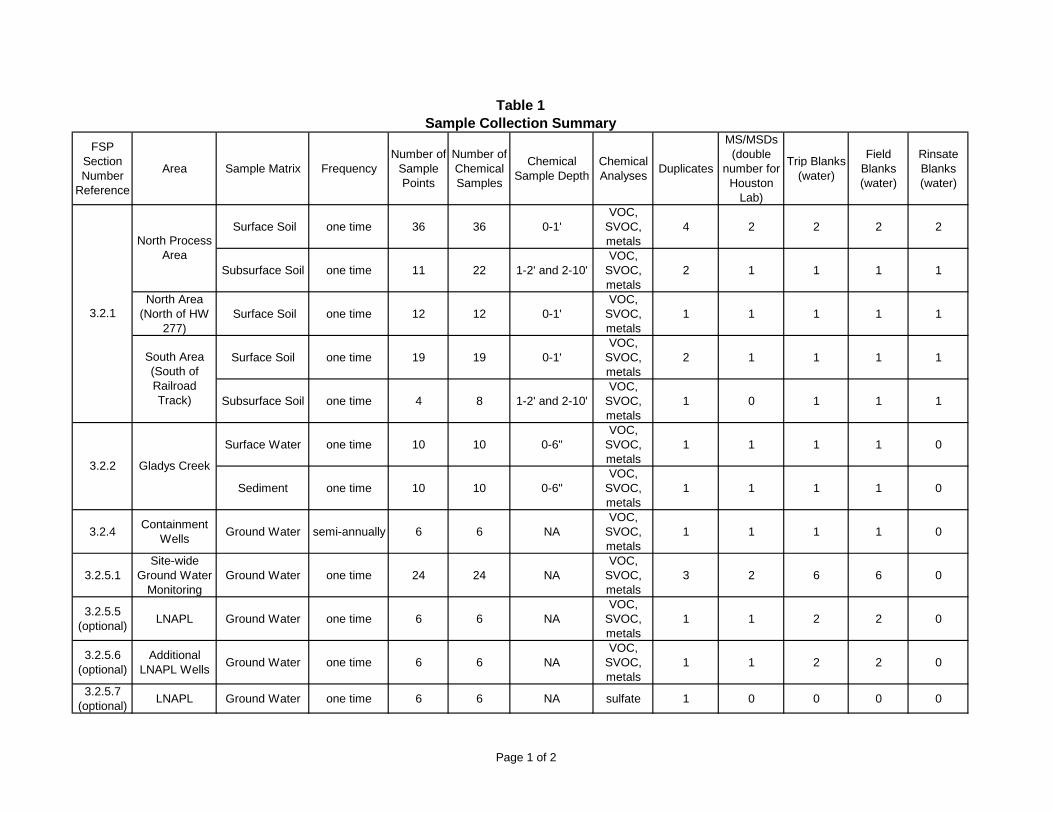
FSP Section Number
Reference
Area Sample Matrix FrequencyNumber of
Sample Points
Number of Chemical Samples
Chemical Sample Depth
Chemical Analyses
Duplicates
MS/MSDs (double
number for Houston
Lab)
Trip Blanks (water)
Field Blanks (water)
Rinsate Blanks (water)
Surface Soil one time 36 36 0-1'VOC,
SVOC, metals
4 2 2 2 2
Subsurface Soil one time 11 22 1-2' and 2-10'VOC,
SVOC, metals
2 1 1 1 1
North Area (North of HW
277) Surface Soil one time 12 12 0-1'
VOC, SVOC, metals
1 1 1 1 1
Surface Soil one time 19 19 0-1'VOC,
SVOC, metals
2 1 1 1 1
Subsurface Soil one time 4 8 1-2' and 2-10'VOC,
SVOC, metals
1 0 1 1 1
Surface Water one time 10 10 0-6"VOC,
SVOC, metals
1 1 1 1 0
Sediment one time 10 10 0-6"VOC,
SVOC, metals
1 1 1 1 0
3.2.4Containment
WellsGround Water semi-annually 6 6 NA
VOC, SVOC, metals
1 1 1 1 0
3.2.5.1Site-wide
Ground Water Monitoring
Ground Water one time 24 24 NAVOC,
SVOC, metals
3 2 6 6 0
3.2.5.5 (optional)
LNAPL Ground Water one time 6 6 NAVOC,
SVOC, metals
1 1 2 2 0
3.2.5.6 (optional)
Additional LNAPL Wells
Ground Water one time 6 6 NAVOC,
SVOC, metals
1 1 2 2 0
3.2.5.7 (optional)
LNAPL Ground Water one time 6 6 NA sulfate 1 0 0 0 0
Table 1Sample Collection Summary
Gladys Creek
North Process Area
South Area (South of Railroad Track)
3.2.1
3.2.2
Page 1 of 2

FSP Section Number
Reference
Area Sample Matrix FrequencyNumber of
Sample Points
Number of Chemical Samples
Chemical Sample Depth
Chemical Analyses
Duplicates
MS/MSDs (double
number for Houston
Lab)
Trip Blanks (water)
Field Blanks (water)
Rinsate Blanks (water)
Table 1Sample Collection Summary
3.2.5.8 (optional)
LNAPL LNAPL one time 6 6 NAVOC,
SVOC, metals
1 1 1 1 0
MNA Wells Ground Water semi-annually 13 13 NA
VOC, SVOC, metals,
methane, gen chem
2 1 4 4 0
New MNA Wells
(optional)Ground Water semi-annually 4 4 NA
VOC, SVOC, metals,
methane, gen chem
1 1 1 1 0
New Source Wells
(optional)Ground Water one time 3 3 NA
VOC, SVOC, metals
1 1 1 1 0
3.2.6
Page 2 of 2

Analysis Matrix Method Container TypeNumber of
Containers Needed for Samples Only
Number of Additional Containers Need for
Samples with MS/MSD
Volume/ Mass Preservative Holding Time
Water SW-846 5030B/ 8260B40 mL amber glass vial, 24
mm neck finish3 6
Fill to capacity w/ no headspace or
air bubbles.
Preserve to a pH of 2 with HCL and cool to 4°C immediately after
collection.
14 days
SW-846 5035A/ 8260B or OLM04.3
Cooring tool used as a transport device (e.g., 5 g
Sampler) and 40 mL amber glass vial, 24 mm neck finish
3 samplers and 1 vial
9 samplers and 1 vialFill with soil, no
headspaceFrozen (-7°C to -15°C)
or iced to 4°C48 hours
SW-846 5035A/ 8260B or OLM04.3
40 mL amber glass vial, 24 mm neck finish, pre-weighed, stir bar and 4 oz (120 mL) tall,
wide mouth, straight-sided, glass jar, 48 mm neck finish
3 vials and 1 - 4oz jar
8 vials
5 g, place samples on side
prior to being frozen
Frozen (-7°C to -15°C) or iced to 4°C
14 days
Soil/ Sediment (Houston
Lab)
SW-846 8260B or OLM04.34 oz (120 mL) tall, wide
mouth, straight-sided, glass jar, 48 mm neck finish
2 0 Fill to capacityCool to 4°C
immediately after collection.
14 days
LNAPL SW-846 5030B/ 8260B40 mL amber glass vial, 24
mm neck finish3 6
Fill to capacity w/ no headspace or
air bubbles.
Cool to 4°C immediately after
collection.14 days
Water SW-846 8270C or OLM04.31 L amber round glass bottle, 33 mm pour-out neck finish
2 4 2 LitterCool to 4°C
immediately after collection.
7 days
Soil/ Sediment
SW-846 8260B or OLM04.38 oz. short, wide mouth,
straight-sided, glass jar, 70 mm neck finish
1 0 Fill to capacityCool to 4°C
immediately after collection.
14 days
LNAPL SW-846 5030B/ 8260B1 L amber round glass bottle, 33 mm pour-out neck finish
2 4 Fill to capacityCool to 4°C
immediately after collection.
7 days
WaterSW-846 6000 or 7000 series or EPA 200 series or ILM05.3
1 L high density polyethylene, cylinder-round bottle, 28 mm
neck finish1 1 1 L
Acidify to pH < 2 with HNO3 and cool to 4°C
immediately after collection.
6 months
Soil/ Sediment
SW-846 6000 or 7000 series or EPA 200 series or ILM05.3
8 oz. short, wide mouth, straight-sided, glass jar, 70
mm neck finish1 1 Fill to capacity
Cool to 4°C immediately after
collection.6 months
Table 2Analytical Methods, Containers, Preservatives, and Holding Times Summary
Soil/ Sediment
(CLP)VOCs
SVOCs
Metals
Page 1 or 2

Analysis Matrix Method Container TypeNumber of
Containers Needed for Samples Only
Number of Additional Containers Need for
Samples with MS/MSD
Volume/ Mass Preservative Holding Time
Table 2Analytical Methods, Containers, Preservatives, and Holding Times Summary
LNAPL SW-846 5030B/ 8260B1 L high density polyethylene, cylinder-round bottle, 28 mm
neck finish1 1 Fill to capacity
Cool to 4°C immediately after
collection.6 months
Methane Water SW-846 3810M of RSK 17540 mL glass vial (provided by
Ana Lab)2 0 Fill to capacity
Cool to 4°C immediately after
collection.7 days
Alkalinity Water EPA 310 Series or SM 2320B 14 days
Nitrite WaterSW-846 9000 Series or EPA
325 Series or EPA 300.048 hours
Nitrate WaterSW-846 9000 Series or EPA
325 Series or EPA 300.048 hours
Sulfate WaterSW-846 9000 Series or EPA
325 Series or EPA 300.028 days
0 Fill to capacityCool to 4°C
immediately after collection.
1 100-mL high-density polyethylene bottle (provided
by SEL Lab)1
Page 2 or 2

ORC SOUTH
ORC NORTH
− 0 0.2 0.4 0.6 0.80.1Miles
FIGURE 1: LOCATION MAP OF THE ORC SUPERFUND SITECYRIL, CADDO COUNTY, OKLAHOMA
Map Created: 11/30/2007

@A
@A
@A@A
@A
@A
@A
@A
@A
@A
@A@A
@A@A
@A
@A@A@A@A
@A@A
@A
@A
@A
@A
@A
@A
@A@A @A
@A@A @A
@A
@A
@A
@A
@A
@A
@A
@A @A@A
@A
@A
@A@A
@A@A
@A@A
@A
@A@A
@A @A@A
@A
@A@A@A
@A
@A
@A@A
@A
@A
@A
IBB-3
SBB-8
IBB-4
IBB-5
SBB-2
SBB-3
IBB-2
SBB-9
SBB-7
SBB-1
OSL-3
SBB-5
SBB-4
RMW-9
OSL-2
RMW-6
SBB-6
SBB-28
SBB-22
RMW-4D
SBB-11
SBB-38
SBB-32
RMW-1D
SBB-10
SBB-36
RMW-3D
SBB-29
SBB-18
SBB-23
DLR-11
SBB-13
DLR-07
DLR-05
DLR-03
DLR-01
DLR-02
DLR-06
SBB-14
SBB-15
SBB-12
SBB-20
RMW-3S
DLR-10
RMW-1S
SBB-37
SBB-24 SBB-17
DOW-07DGR-03
DOW-08
RMW-10
RMW-4SSBB-16
SBB-30
SBB-19
SBB-31
SBB-34
SBB-25
OSL-1
SBB-35
RMW-2D
DLR-04
SBB-21
RMW-2S
SBB-27
DOW-03
SBB-33
FIGURE 2: MONITORING WELL LOCATIONS
Legend
@A Monitoring Wells
ORC Site Boundary .410 0 410205 Feet
Map Created 11/30/2007
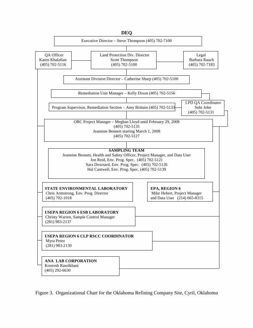
DEQ
Executive Director – Steve Thompson (405) 702-7100
QA Officer Land Protection Div. Director Legal Karen Khalafian Scott Thompson Barbara Rauch (405) 702-5116 (405) 702-5100 (405) 702-7183
Assistant Division Director – Catherine Sharp (405) 702-5100
Remediation Unit Manager – Kelly Dixon (405) 702-5156
LPD QA Coordinator Program Supervisor, Remediation Section – Amy Brittain (405) 702-5133 Subi John
(405) 702-5131
ORC Project Manager – Meghan Lloyd until February 29, 2008 (405) 702-5135
Jeannine Bennett starting March 1, 2008 (405) 702-5127
SAMPLING TEAM Jeannine Bennett, Health and Safety Officer, Project Manager, and Data User
Jon Reid, Env. Prog. Spec. (405) 702-5121 Sara Downard, Env. Prog. Spec. (405) 702-5126 Hal Cantwell, Env. Prog. Spec. (405) 702-5139
STATE ENVIRONMENTAL LABORATORY EPA, REGION 6 Chris Armstrong, Env. Prog. Director Mike Hebert, Project Manager
(405) 702-1018 and Data User (214) 665-8315 USEPA REGION 6 ESB LABORATORY Christy Warren, Sample Control Manager (281) 983-2137
USEPA REGION 6 CLP RSCC COORDINATOR Myra Perez (281) 983-2130
ANA � LAB CORPORATION Koorosh Rasolkhani (405) 292-6630
Figure 3. Organizational Chart for the Oklahoma Refining Company Site, Cyril, Oklahoma
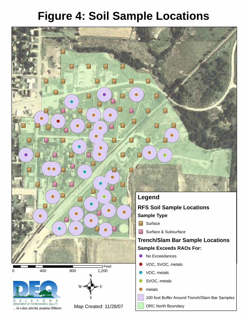
!
!
!
!
!
!
! !!
!
!!!
!
!
!!!
!
!!
!!
!
!
!
!!
!
!
!
!!
UW UW
UW
UWUW UW
UW UW UW
UW
UW
UW UWUW
UW UW
UW
UW
UW
UW UW UW UW UW UW
UW
UW
UWUW
UW
UW UW UW UW UW UW UW
UW
UW UW UW UWUW
UW UW
UW UW UW UW UW UW
UWUW UW UW
UW UW
UW
UW UW UW UW
UW UW UW UW
UW
LegendRFS Soil Sample LocationsSample Type
UW Surface
UW Surface & Subsurface
Trench/Slam Bar Sample LocationsSample Exceeds RAOs For:! No Exceedances
! VOC, SVOC, metals
! VOC, metals
! SVOC, metals
! metals
100 foot Buffer Around Trench/Slam Bar Samples
ORC North Boundary
0 400 800 1,200Feet
Figure 4: Soil Sample Locations
Map Created: 11/28/07
.
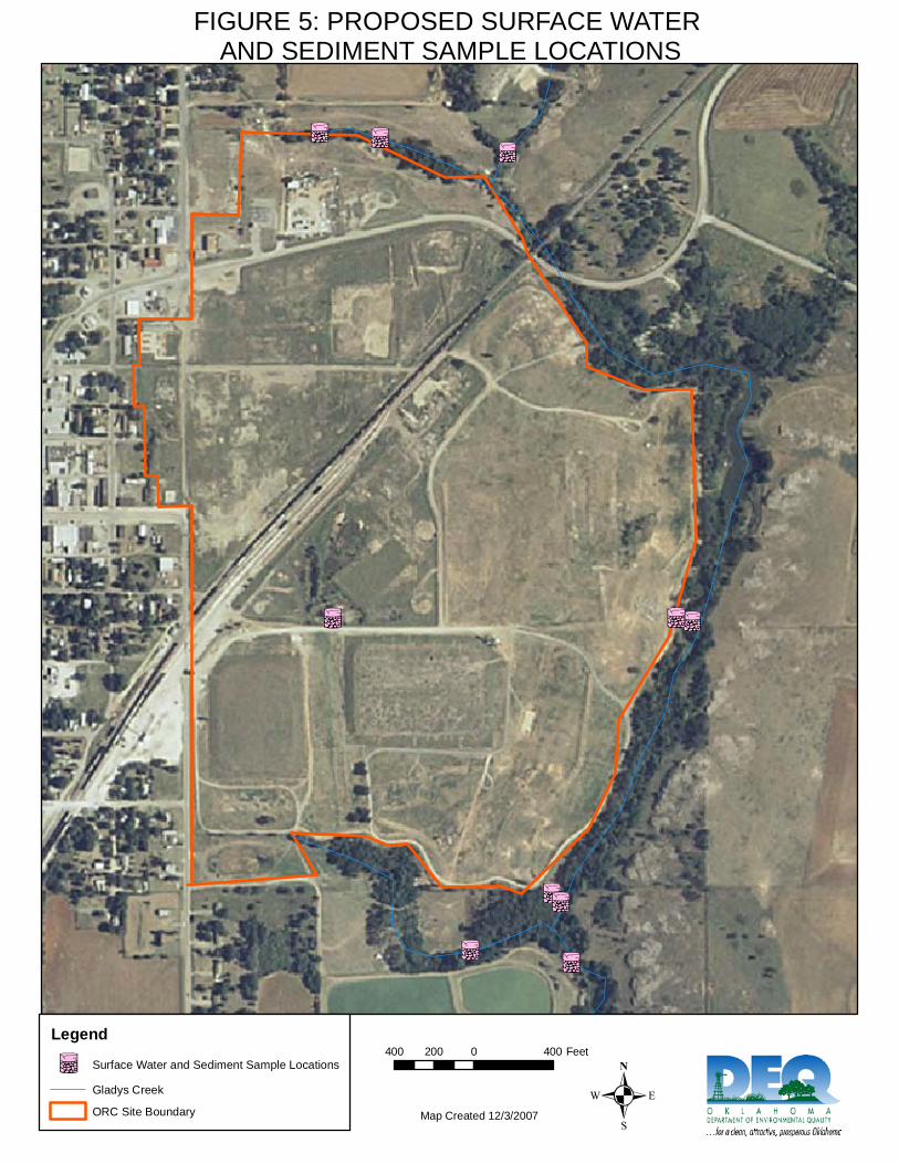
ILIL
IL
ILIL
ILIL
ILILIL
FIGURE 5: PROPOSED SURFACE WATER AND SEDIMENT SAMPLE LOCATIONS
Legend
IL Surface Water and Sediment Sample Locations
Gladys Creek
ORC Site Boundary .400 0 400200 Feet
Map Created 12/3/2007
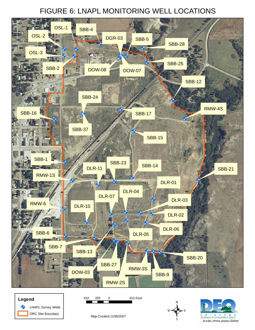
@A
@A@A@A@A
@A
@A@A@A
@A
@A
@A
@A @A
@A
@A@A @A
@A@A @A
@A
@A
@A
@A
@A
@A
@A
@A
@A @A@A
@A
@A
@A@A
@A
@A
@A
@A@A@A
SBB-2
SBB-9
SBB-7
SBB-6
RMW-6
SBB-1
SBB-5
SBB-4
SBB-16
SBB-28
SBB-23DLR-11
SBB-13
DLR-07
DLR-05
DLR-03
DLR-04
DLR-01
DLR-02
SBB-14
SBB-15
SBB-12
RMW-4S
SBB-21
SBB-20
RMW-3S
RMW-2S
SBB-27
DLR-10
RMW-1S
SBB-37
SBB-24
SBB-17
SBB-25DOW-07
DGR-03
DOW-08
DLR-06
DOW-03
OSL-3
OSL-2
OSL-1
FIGURE 6: LNAPL MONITORING WELL LOCATIONS
Legend
@A LNAPL Survey Wells
ORC Site Boundary .410 0 410205 Feet
Map Created 11/30/2007
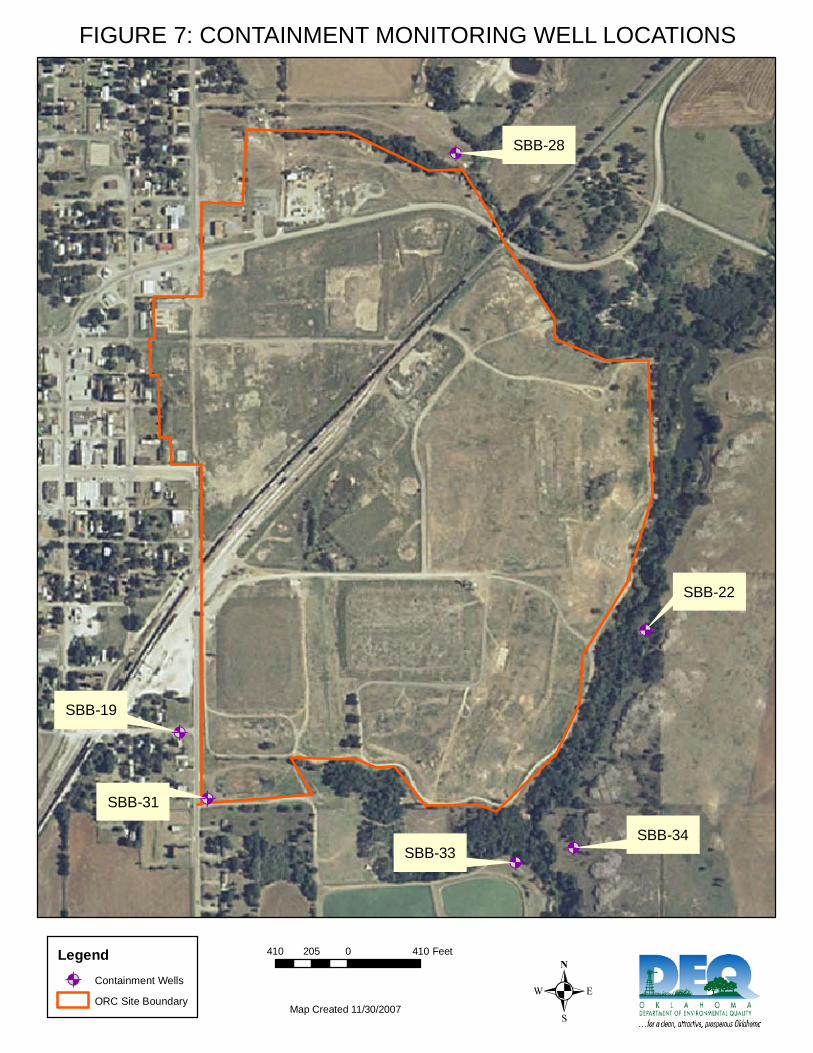
@A
@A@A
@A
@A
@ASBB-28
SBB-19
SBB-31
SBB-33SBB-34
SBB-22
FIGURE 7: CONTAINMENT MONITORING WELL LOCATIONS
Legend
@A Containment Wells
ORC Site Boundary .410 0 410205 Feet
Map Created 11/30/2007
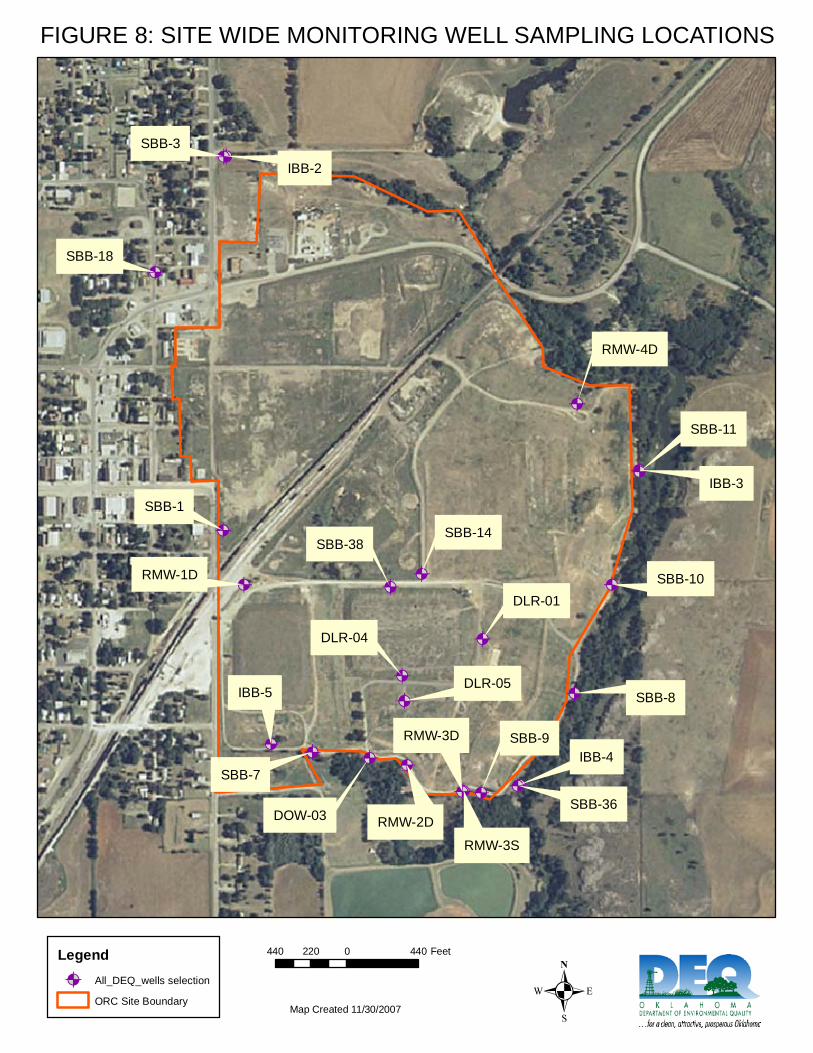
@A
@A @A
@A@A
@A
@A
@A
@A
@A
@A@A
@A@A
@A @A@A
@A
@A@A @A
@A@A
@A
IBB-3
SBB-8
IBB-4
IBB-5
SBB-3
IBB-2
SBB-9
SBB-7
SBB-1
RMW-4D
SBB-11
SBB-38
RMW-1D SBB-10
SBB-36
RMW-3D
RMW-2D
SBB-18
DLR-05
DLR-04
DLR-01
SBB-14
RMW-3S
DOW-03
FIGURE 8: SITE WIDE MONITORING WELL SAMPLING LOCATIONS
Legend
@A All_DEQ_wells selection
ORC Site Boundary .440 0 440220 Feet
Map Created 11/30/2007

@A
@A
@A
@A
@A
@A
@A@A
@A
@A
@A
@A
@A
RMW-9
RMW-6
SBB-6
SBB-13
SBB-21
SBB-20
RMW-2S
SBB-17
RMW-10
RMW-4SSBB-16
SBB-30
SBB-25
FIGURE 9: MNA MONITORING WELL SAMPLING LOCATIONS
Legend
@A MNA Wells
ORC Site Boundary .440 0 440220 Feet
Map Created 12/3/2007
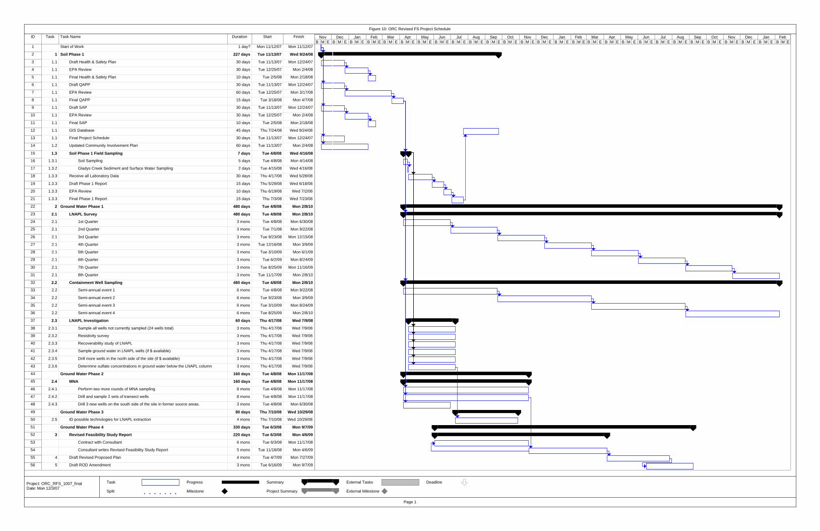
ID Task Task Name Duration Start Finish
1 Start of Work 1 day? Mon 11/12/07 Mon 11/12/07
2 1 Soil Phase 1 227 days Tue 11/13/07 Wed 9/24/08
3 1.1 Draft Health & Safety Plan 30 days Tue 11/13/07 Mon 12/24/07
4 1.1 EPA Review 30 days Tue 12/25/07 Mon 2/4/08
5 1.1 Final Health & Safety Plan 10 days Tue 2/5/08 Mon 2/18/08
6 1.1 Draft QAPP 30 days Tue 11/13/07 Mon 12/24/07
7 1.1 EPA Review 60 days Tue 12/25/07 Mon 3/17/08
8 1.1 Final QAPP 15 days Tue 3/18/08 Mon 4/7/08
9 1.1 Draft SAP 30 days Tue 11/13/07 Mon 12/24/07
10 1.1 EPA Review 30 days Tue 12/25/07 Mon 2/4/08
11 1.1 Final SAP 10 days Tue 2/5/08 Mon 2/18/08
12 1.1 GIS Database 45 days Thu 7/24/08 Wed 9/24/08
13 1.1 Final Project Schedule 30 days Tue 11/13/07 Mon 12/24/07
14 1.2 Updated Community Involvement Plan 60 days Tue 11/13/07 Mon 2/4/08
15 1.3 Soil Phase 1 Field Sampling 7 days Tue 4/8/08 Wed 4/16/08
16 1.3.1 Soil Sampling 5 days Tue 4/8/08 Mon 4/14/08
17 1.3.2 Gladys Creek Sediment and Surface Water Sampling 2 days Tue 4/15/08 Wed 4/16/08
18 1.3.3 Receive all Laboratory Data 30 days Thu 4/17/08 Wed 5/28/08
19 1.3.3 Draft Phase 1 Report 15 days Thu 5/29/08 Wed 6/18/08
20 1.3.3 EPA Review 10 days Thu 6/19/08 Wed 7/2/08
21 1.3.3 Final Phase 1 Report 15 days Thu 7/3/08 Wed 7/23/08
22 2 Ground Water Phase 1 480 days Tue 4/8/08 Mon 2/8/10
23 2.1 LNAPL Survey 480 days Tue 4/8/08 Mon 2/8/10
24 2.1 1st Quarter 3 mons Tue 4/8/08 Mon 6/30/08
25 2.1 2nd Quarter 3 mons Tue 7/1/08 Mon 9/22/08
26 2.1 3rd Quarter 3 mons Tue 9/23/08 Mon 12/15/08
27 2.1 4th Quarter 3 mons Tue 12/16/08 Mon 3/9/09
28 2.1 5th Quarter 3 mons Tue 3/10/09 Mon 6/1/09
29 2.1 6th Quarter 3 mons Tue 6/2/09 Mon 8/24/09
30 2.1 7th Quarter 3 mons Tue 8/25/09 Mon 11/16/09
31 2.1 8th Quarter 3 mons Tue 11/17/09 Mon 2/8/10
32 2.2 Containment Well Sampling 480 days Tue 4/8/08 Mon 2/8/10
33 2.2 Semi-annual event 1 6 mons Tue 4/8/08 Mon 9/22/08
34 2.2 Semi-annual event 2 6 mons Tue 9/23/08 Mon 3/9/09
35 2.2 Semi-annual event 3 6 mons Tue 3/10/09 Mon 8/24/09
36 2.2 Semi-annual event 4 6 mons Tue 8/25/09 Mon 2/8/10
37 2.3 LNAPL Investigation 60 days Thu 4/17/08 Wed 7/9/08
38 2.3.1 Sample all wells not currently sampled (24 wells total) 3 mons Thu 4/17/08 Wed 7/9/08
39 2.3.2 Resistivity survey 3 mons Thu 4/17/08 Wed 7/9/08
40 2.3.3 Recoverability study of LNAPL 3 mons Thu 4/17/08 Wed 7/9/08
41 2.3.4 Sample ground water in LNAPL wells (if $ available) 3 mons Thu 4/17/08 Wed 7/9/08
42 2.3.5 Drill more wells in the north side of the site (if $ available) 3 mons Thu 4/17/08 Wed 7/9/08
43 2.3.6 Determine sulfate concentrations in ground water below the LNAPL column 3 mons Thu 4/17/08 Wed 7/9/08
44 Ground Water Phase 2 160 days Tue 4/8/08 Mon 11/17/08
45 2.4 MNA 160 days Tue 4/8/08 Mon 11/17/08
46 2.4.1 Perform two more rounds of MNA sampling 8 mons Tue 4/8/08 Mon 11/17/08
47 2.4.2 Drill and sample 2 sets of transect wells 8 mons Tue 4/8/08 Mon 11/17/08
48 2.4.3 Drill 3 new wells on the south side of the site in former source areas. 3 mons Tue 4/8/08 Mon 6/30/08
49 Ground Water Phase 3 80 days Thu 7/10/08 Wed 10/29/08
50 2.5 ID possible technologies for LNAPL extraction 4 mons Thu 7/10/08 Wed 10/29/08
51 Ground Water Phase 4 330 days Tue 6/3/08 Mon 9/7/09
52 3 Revised Feasibility Study Report 220 days Tue 6/3/08 Mon 4/6/09
53 Contract with Consultant 6 mons Tue 6/3/08 Mon 11/17/08
54 Consultant writes Revised Feasibility Study Report 5 mons Tue 11/18/08 Mon 4/6/09
55 4 Draft Revised Proposed Plan 4 mons Tue 4/7/09 Mon 7/27/09
56 5 Draft ROD Amendment 3 mons Tue 6/16/09 Mon 9/7/09
B M E B M E B M E B M E B M E B M E B M E B M E B M E B M E B M E B M E B M E B M E B M E B M E B M E B M E B M E B M E B M E B M E B M E B M E B M E B M E B M E B M ENov Dec Jan Feb Mar Apr May Jun Jul Aug Sep Oct Nov Dec Jan Feb Mar Apr May Jun Jul Aug Sep Oct Nov Dec Jan Feb
Task
Split
Progress
Milestone
Summary
Project Summary
External Tasks
External Milestone
Deadline
Figure 10: ORC Revised FS Project Schedule
Page 1
Project: ORC_RFS_1007_finalDate: Mon 12/3/07

Appendix A

SUPERFUND DEPARTMENT OF ENVIRONMENTAL QUALITY Chain of Custody Record
--.-~ --- ~
Site Name: Site Location: Code: ~" ~ i-1 .;;::" ~ ~
L: .Q .-,:,
~ ~ c: '" S.E.L. ~ ,0, 6 '" ;:, ..., <t ~ "- Numbers '1J
~ ..., 'b ... / u s £" '" Sarnple Location Date Tillie
c-.0 l:> ~ Q,
l.:J
-- -
-------'r--.---- ---- ,
- --
- --I---"
----.--
\ --
. --~
- --
- --
Sampler's Signature (Relinquishea by): Received by:
nelinquished by: Received by:
Relinquished by: Received by:
Remarks:
A Indicate the number of containers for each analysis in the proper column.

FOR LAB USE ONLY:
PROJECT CODE: ORC-WX SELS SAMPLE NO._____________________
DEPARTMENT OF ENVIRONMENTAL QUALITY STATE ENVIRONMENTAL LABORATORY P. O. BOX 1677 OKLAHOMA CITY, OK, 73101 (Physical location) 707 N. ROBINSON OKLAHOMA CITY, OK 73102
ORC PROJECT Collector’s Initial: __________ Source: ORC ground water Date Collected: ____/____/____ Time Collected: ____:____ Site Identification Code: _______________________________ City: Cyril County: Caddo Sample Description: ____________________________________________________________________ Sampler’s Comments: ________________________________________________________________ Collect in 1 liter plastic bottle/site
Alkalinity Nitrate Nitrite Sulfate
Report to: Land Protection Division File Copy Amy Brittain

ANAeIJlP.! (OKP.~ I
THE COMPLETE SERVICE LAB.
Amy Brittain Oklahoma DEQ P.O. Box 1677
Ana-Lab Corporate Laboratory
Phone 90J/9S-t-OSS I FAX 903/98"-59 U e-Mail
Chain of Custody DEQO
101
Oklahoma CIty, OK 73101-1677 Monitoring Wells
P.o. Box 9000 h:.ilgorc, TX 75663
NE LAP-acc rcditcd #0200S
0912212006
Lab Number
Phone Fax
405/702-5133 4051702-5101
Page 1 of2
Matrix: Liquid A ueous
Printed Name
Name
!CH4 Dissolved Methane Exp
Ana-Lab # SampleID
Ambient Conditions
Comments
ISO-17025 # 0637-01
WSClient v2.0.5 0210112006
Affiliation Signature
D ""Glass Vial 40 mL (Zero Headspace) wffeflon lined lid-2 Requested Test Methods
RSK 175
Bottles Date Time Notes
MEMBER
~IL _._--', NELAP-accredited #02008 2004 Seal of Excellence
Form rptcocproj Created 612212004 vi. 7
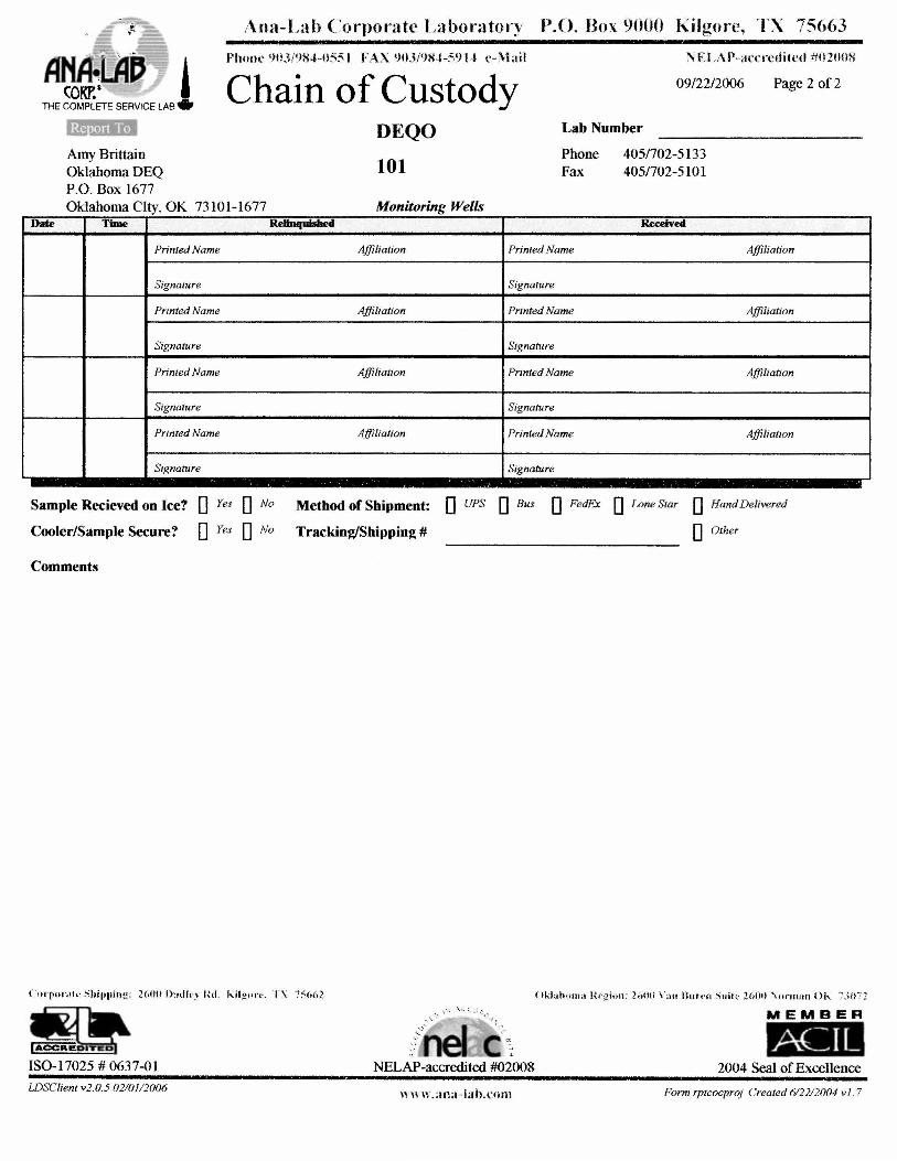
Ana-Lab Coq)orate Labora tory P.o. Box 9000 KilgOl'e, TX 75663
AMOIp ! COKP.~
THE COMPLETE SERVICE LAB
PhI/ill' ,)1l3NS~-05:\ I FAX <)\)J/')S-t-59J..t c- Mail NELA P-a{'crcdilcd #02Hml
Chain of Custody 0912212006 Page 2 of2
DEQO
101
Lab Number
Date
Amy Brittain Oklahoma DEQ P.O. Box 1677 Oklahoma CIty, OK 73101-1677
Time
Printed Name
Signature
Printed Name
Signature
Printed Name
Signature
Printed Name
Signature
Monitoring Wells ReIIu.c[uishe4
Affiliation
Affiliation
Affiliation
Affiliation
Phone Fax
Printed Name
Signature
Printed Name
Signature
Printed Name
Signature
Printed Name
Signature
405/702-5133 405/702-5101
Received
Affiliation
Affiliation
Affiliation
Affiliation
Sample Recieved on Ice? 0 Yes 0 No
Cooler/Sample Secure? 0 Yes 0 No
Method of Shipment: 0 UPS 0 Bus 0 FedEx 0 Lone Star 0 Hand Delivered
Tracking/Shipping # 0 Other
Comments
( ." •. p . .... ).., shil)pillg: 26flH Ou<ll.· \ I{ d. ldlg""'·. L\ 7:"(,62 ... ISO-17025 # 0637-01
WSClientv2.0.5 02l0112oo6
.:. ~ I\. :, ,~ :;" .., "'- '
NELAP-accredited #02008
\\ " n.aoa-!alu:.nm
MEMBER
ACJL 2004 Seal of Excellence
Form rptcocproj Created 612212004 v J. 7
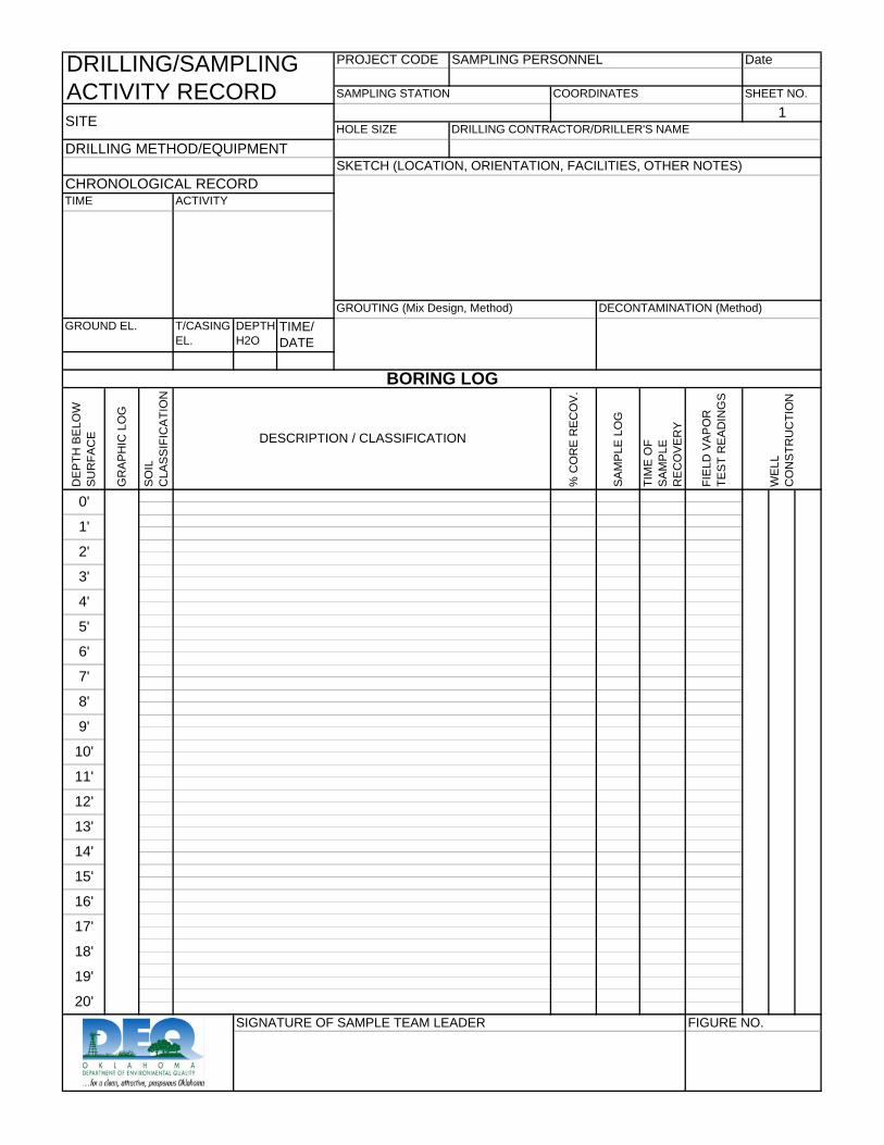
PROJECT CODE
HOLE SIZE
T/CASING EL.
DEPTH H2O
TIME/ DATE
FIGURE NO.
SAMPLING PERSONNEL
DRILLING CONTRACTOR/DRILLER'S NAME
WE
LL
CO
NS
TRU
CTI
ON
GROUTING (Mix Design, Method)
COORDINATESSAMPLING STATION
SO
IL
CLA
SS
IFIC
ATI
ON
GROUND EL.
SKETCH (LOCATION, ORIENTATION, FACILITIES, OTHER NOTES)
ACTIVITY
1
DRILLING/SAMPLING ACTIVITY RECORD SHEET NO.
Date
0'
FIE
LD V
AP
OR
TE
ST
RE
AD
ING
S
DE
PTH
BE
LOW
S
UR
FAC
E DESCRIPTION / CLASSIFICATION
DECONTAMINATION (Method)
BORING LOG
GR
AP
HIC
LO
G
% C
OR
E R
EC
OV
.
TIME
1'
2'
3'
TIM
E O
F S
AM
PLE
R
EC
OV
ER
Y
SA
MP
LE L
OG
4'
5'
6'
7'
8'
SIGNATURE OF SAMPLE TEAM LEADER
9'
10'
11'
12'
13'
14'
15'
16'
17'
18'
19'
20'
SITE
DRILLING METHOD/EQUIPMENT
CHRONOLOGICAL RECORD
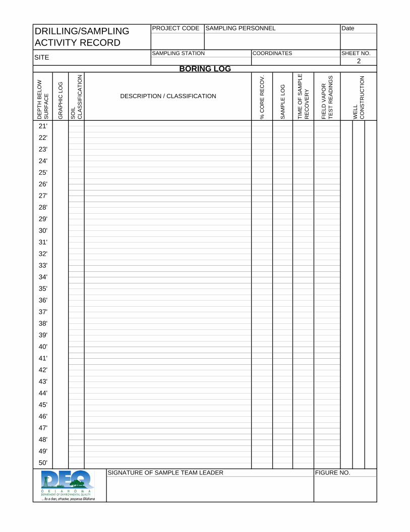
PROJECT CODE
45'
46'
49'
FIGURE NO.SIGNATURE OF SAMPLE TEAM LEADER
38'
39'
48'
50'
40'
41'
42'
47'
43'
44'
36'
37'
34'
35'
32'
33'
30'
31'
28'
29'
26'
27'
24'
25'
22'
23'
21'
% C
OR
E R
EC
OV
.
SHEET NO.2
DateDRILLING/SAMPLING ACTIVITY RECORD
SAMPLING PERSONNEL
SAMPLING STATION COORDINATESSITE
BORING LOG
DESCRIPTION / CLASSIFICATION
TIM
E O
F S
AM
PLE
R
EC
OV
ER
Y
SO
IL
CLA
SS
IFIC
ATI
ON
SA
MP
LE L
OG
DE
PTH
BE
LOW
S
UR
FAC
E
GR
AP
HIC
LO
G
FIE
LD V
AP
OR
TE
ST
RE
AD
ING
S
WE
LL
CO
NS
TRU
CTI
ON

Appendix B
Standard Operating Procedure (SOP)
Field Logbooks Sample Logbooks
SOP~ 1 Logbooks Rev.#2
Date: 08.02.2006 Page 1 of3
.)!y/{~ Prepared and Approved by:-::-~~ ~~/ "-----,) I /.
Date: r:f'/ 2/ ti6" fl Karen Khalafiaii
ODEQ QA Officer
/ ---~-,~
if" (~) Approved by: ---~'f3' :;:-,--'--"'"''''-''' .. _=....:'--=""'-...... =-:::::;.::::.~ __ ~_
I Kelly Dixon ' Date:
Environmental Programs Manager
« ).
Approved by: ):v:.{~j;{y / Date: _...;'>; ..... ' -~? _'_' .::c:.~'~ AmilLyon'
Environmental Programs Manager
"
<'~-:.;:> /1,/ '''\ <:/ /
Approved by: __ , =_:_'-,,-~_I_) _v1_)t_<-_~_i_,·l_.,,_ .. __ -_-~_---_. ' __ _ ') .-. Ch Date: _____ _
Scott Thompson Land Protection Division Director
Site Remediation Section Voluntary Cleanup & Brownfields Section
Land Protection Division Oklahoma DEQ
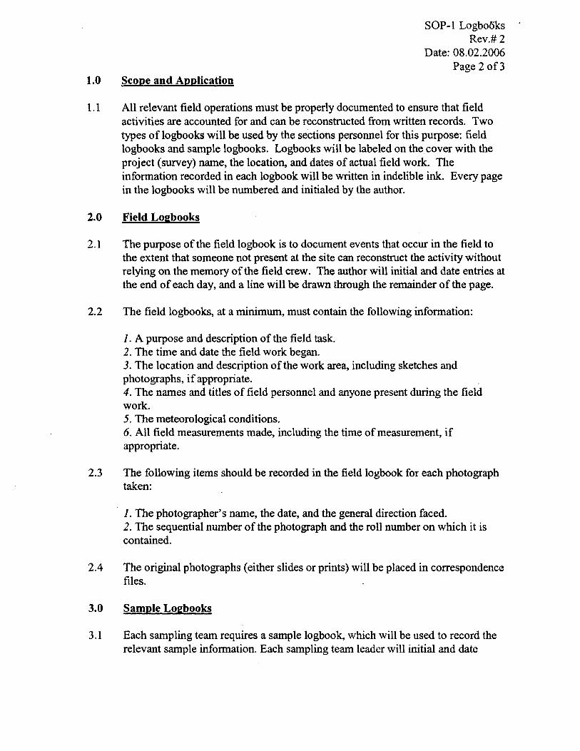
1.0 Scope and Application
SOP-1 Logbooks Rev.# 2
Date: 08.02.2006 Page 20f3
1.1 All relevant field operations must be properly documented to ensure that field activities are accounted for and can be reconstructed from written records. Two types of logbooks will be used by the sections personnel for this purpose: field logbooks and sample logbooks. Logbooks will be labeled on the cover with the project (survey) name, the location, and dates of actual field work. The information recorded in each logbook will be written in indelible ink. Every page in the logbooks will be numbered and initialed by the author.
2.0 Field Logbooks
2.1 The purpose of the field logbook is to document events that occur in the field to the extent that someone not present at the site can reconstruct the activity without relying on the memory of the field crew. The author will initial and date entries at the end of each day, and a line will be drawn through the remainder of the page.
2.2 The field logbooks, at a minimum, must contain the following information:
1. A purpose and description of the field task. 2. The time and date the field work began. 3. The location and description of the work area, including sketches and photographs, if appropriate. 4. The names and titles of field personnel and anyone present during the field work. 5. The meteorological conditions. 6. All field measurements made, including the time of measurement, if appropriate.
2.3 The following items should be recorded in the field logbook for each photograph taken:
1. The photographer's name, the date, and the general direction faced. 2. The sequential number of the photograph and the roll number on which it is contained.
2.4 The original photographs (either slides or prints) will be placed in correspondence files.
3.0 Sample Logbooks
3.1 Each sampling team requires a sample logbook, which will be used to record the relevant sample information. Each sampling team leader will initial and date

SOP-l Logbooks Rev.# 2
Date: 08.02.2006 Page 3 of3
entries at the end of sampling event, and a line will be drawn through the remainder of the page.
3.2 General information recorded in the sample logbooks must include:
1. Date and time of sample collection. 2. Weather conditions. 3. Names of individuals participating in and/or observing sampling.
3.3 The project sample logbooks require the following information:
1. Sample number. 2. Sample location. 3. Any observations or comments relevant to the sampling procedure, including sample appearance. 4. All field measurements made, including the time of measurement, if appropriate.
3.4 The following items should be recorded in the field logbook for each photograph taken:
1. The photographer's name, the date, and the general direction faced. 2. The sequential number of the photograph and the roll number on which it is contained.

Standard Operating Procedure (SOP)
Field Instruments
Date:
/
SOP-2 INSTR Rev.#2
Date:08.02.2006 Page 1 of9
../ /' . /~----,--,,)
Approved by: ----" . .::...~<::~L__==~s__......l_-.-..-"'---~.-·----~-/-~ Kelly DIxon
Date: .l /2-,- () G Environmental Programs Manager
Date: Approved by: ______ ---'-' ...,." ____ ----.;;'------Amil Lyon
-----Environmental Programs Manager
Date: Scott Thompson
Land Protection Division Director
Site Remediation Section Voluntary Cleanup & Brownfields Section
Land Protection Division Oklahoma DEQ
r
? ~7 - /'(;
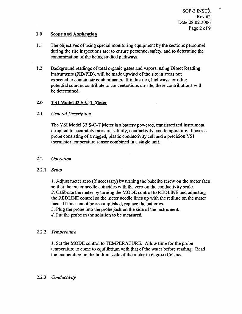
1.0 Scope and Application
SOP-2 INSTR Rev.#2
Date:08.02.2006 Page 2 of9
1.1 The objectives of using special monitoring equipment by the sections personnel during the site inspections are: to ensure personnel safety, and to determine the contamination of the being studied pathways.
1.2 Background readings of total organic gases and vapors, using Direct Reading Instruments (FIDIPID), will be made upwind of the site in areas not expected to contain air contaminants. If industries, highways, or other potential sources contribute to concentrations on-site, these contributions will be determined.
2.0 YSI Model 33 S-C-T Meter
2.1 General Description
The YSI Model 33 S-C-T Meter is a battery powered, transistorized instrument designed to accurately measure salinity, conductivity, and temperature. It uses a probe consisting of a rugged, plastic conductivity cell and a precision YSI thermistor temperature sensor combined in a single unit.
2.2 Operation
2.2.1 Setup
1. Adjust meter zero (if necessary) by turning the bakelite screw on the meter face so that the meter needle coincides with the zero on the conductivity scale. 2. Calibrate the meter by turning the MODE control to REDLINE and adjusting the REDLINE control so the meter needle lines up with the redline on the meter face. If this cannot be accomplished, replace the batteries. 3. Plug the probe into the probe jack on the side ofthe instrument. 4.Put the probe in the solution to be measured.
2.2.2 Telnperature
1. Set the MODE control to TEMPERATURE. Allow time for the probe temperature to come to equilibrium with that of the water before reading. Read the temperature on the bottom scale of the meter in degrees Celsius.
2.2.3 Conductivity
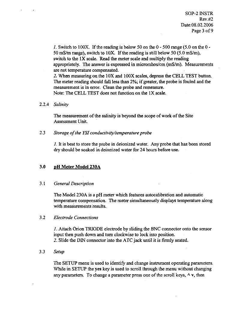
SOP-2 INSTR Rev.#2
Date:08.02.2006 Page 3 of9
1. Switch to 100X. If the reading is below 50 on the 0 - 500 range (5.0 on the 0-50 mS/m range), switch to lOX. If the reading is still below 50 (5.0 mS/m), switch to the IX scale. Read the meter scale and multiply the reading appropriately. The answer is expressed in micromhoslcm (mS/m). Measurements are not temperature compensated. 2. When measuring on the 10X and 100X scales, depress the CELL TEST button. The meter reading should fall less than 2%; if greater, the probe is fouled and the measurement is in error. Clean the probe and remeasure. Note: The CELL TEST does not function on the IX scale.
2.2.4 Salinity
The measurement of the salinity is beyond the scope of work of the Site Assessment Unit.
2.3 Storage of the YSI conductivity/temperature probe
1. It is best to store the probe in deionized water. Any probe that has been stored dry should be soaked in deionized water for 24 hours before use.
3.0 pH Meter Model 230A
3.1 General Description
The Model 230A is a pH meter which features autocalibration and automatic temperature compensation. The meter simultaneously displays temperature along with measurements results.
3.2 Electrode Connections
1. Attach Orion TRIODE electrode by sliding the BNC connector onto the sensor input then push down and turn clockwise to lock into position. 2. Slide the DIN connector into the ATC jack until it is finnly seated.
3.3 Setup
The SETUP menu is used to identify and change instrument operating parameters. While in SETUP the yes key is used to scroll through the menu without changing any parameters. To change a parameter press one of the scroll keys, A v, then
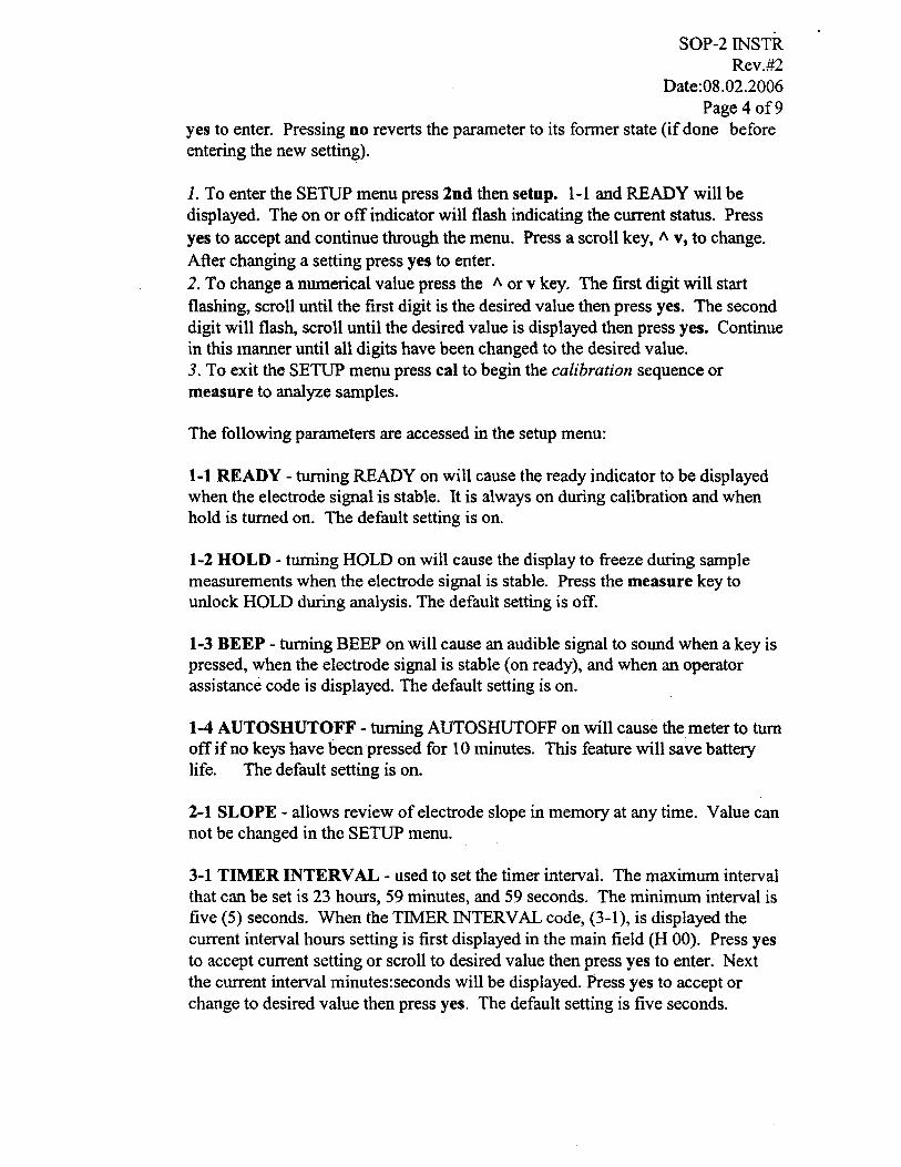
SOP-2 INSTR Rev.#2
Date:08.02.2006 Page 40f9
yes to enter. Pressing no reverts the parameter to its fonner state (if done before entering the new setting).
1. To enter the SETUP menu press 2nd then setup. 1-1 and READY will be displayed. The on or off indicator will flash indicating the current status. Press yes to accept and continue through the menu. Press a scroll key, /I. v, to change. After changing a setting press yes to enter. 2. To change a numerical value press the /I. or v key. The first digit will start flashing, scroll until the first digit is the desired value then press yes. The second digit will flash, scroll until the desired value is displayed then press yes. Continue in this manner until all digits have been changed to the desired value. 3. To exit the SETUP menu press cal to begin the calibration sequence or measure to analyze samples.
The following parameters are accessed in the setup menu:
1-1 READY - turning READY on will cause the ready indicator to be displayed when the electrode signal is stable. It is always on during calibration and when hold is turned on. The default setting is on.
1-2 HOLD - turning HOLD on will cause the display to freeze during sample measurements when the electrode signal is stable. Press the measure key to unlock HOLD during analysis. The default setting is off.
1-3 BEEP - turning BEEP on will cause an audible signal to sound when a key is pressed, when the electrode signal is stable (on ready), and when an operator assistance code is displayed. The default setting is on.
1-4 AUTOSHUTOFF - turning AUTOSHUTOFF on will cause the meter to turn off if no keys have been pressed for 10 minutes. This feature will save battery life. The default setting is on.
2-1 SLOPE - allows review of electrode slope in memory at any time. Value can not be changed in the SETUP menu.
3-1 TIMER INTERVAL - used to set the timer interval. The maximum interval that can be set is 23 hours, 59 minutes, and 59 seconds. The minimum interval is five (5) seconds. When the TIMER INTERVAL code, (3-1), is displayed the current interval hours setting is first displayed in the main field (H 00). Press yes to accept current setting or scroll to desired value then press yes to enter. Next the current interval minutes:seconds will be displayed. Press yes to accept or change to desired value then press yes. The default setting is five seconds.

SOP-2lNSTR Rev.#2
Date:08.02.2006 Page 5 of9
3-2 TIME REMAINING - allows review ofthe time remaining before the TIMER is set to go off. If the timer has not been activated 00:00 will be displayed.
3.4 Calibration and Measurement Procedures
A one or two buffer calibration should be performed before pH is measured. It is recommended that a two buffer calibration using buffers that bracket the expected sample range be performed at the beginning of each day to determine the slope of the electrode. This serves the dual pwpose of determining if the electrode is working properly and storing the slope value in memory. Perform a one buffer calibration every two hours to compensate for electrode drift. Prior to calibration, scroll through the setup menu and ensure all parameters are set correctly for the analysis you want to perform. There are two ways of calibrating the 230A Meter: autocalibration or manual calibration.
3.4.1 Autocalibration with Two Buffers
1. Connect electrode(s) to meter. Choose either 4.01 and 7.00, or 7.00 and 10.01 buffers, whichever will bracket your expected sample range. 2. Place electrode(s) into either 4.01, 7.00, or 10.01 buffer. 3. Press cal. CALIBRATION is displayed above the main readout and PI is displayed in the lower field. PI indicates that the meter is ready for the first buffer. When the electrode is stable the READY prompt will be displayed ,and the temperature-corrected value for the buffer is displayed. Press yes: The display will remain frozen for two seconds then P2 will be displayed in the lower field indicating the meter is ready for the second buffer. 4. Rinse electrode(s) and place in second buffer. Wait for a stable pH display and press yes. After the second buffer value has been entered the electrode slope will be displayed. SLP appears in the lower field while the actual electrode slope (in percent) appears in the main field. The meter automatically advances to the measure mode. MEASURE is displays above the main field. 5. Rinse electrodes and place into sample. Record pH and temperature directly from the meter display.
3.4.2 Autocalibration with One Buffer
1. Connect electrode(s) to meter. Select one buffer, either 4.01, 7.00, or 10.01 whichever most closely approximates the expected sample pH. 2. Place electrodes into the buffer and press cal. CALIBRATE will be displayed above the main field and PI will be displayed in the lower field. 3. Wait for a stable reading (the display will flash) and press yes. The display will remain frozen for two seconds then P2 will be displayed in the lower field.
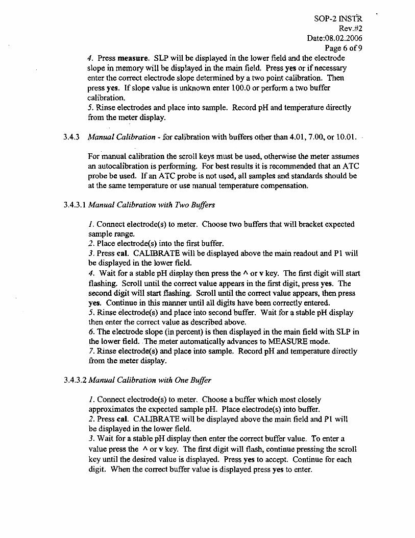
SOP-2lNSTR Rev. #2
Date:08.02.2006 Page 60f9
4. Press measure. SLP will be displayed in the lower field and the electrode slope in memory will be displayed in the main field. Press yes or if necessary enter the correct electrode slope determined by a two point calibration. Then press yes. If slope value is unknown enter 100.0 or perform a two buffer calibration. 5. Rinse electrodes and place into sample. Record pH and temperature directly from the meter display.
3.4.3 Manual Calibration - for calibration with buffers other than 4.01, 7.00, or 10.01.
For manual calibration the scroll keys must be used, otherwise the meter assumes an autocalibration is performing. For best results it is recommended that an ATC probe be used. If an ATC probe is not used, all samples and standards should be at the same temperature or use manual temperature compensation.
3.4.3.1 Manual Calibration with Two Buffers
1. Connect electrode(s) to meter. Choose two buffers that will bracket expected sample range. 2. Place electrode(s) into the first buffer. 3. Press cal. CALIBRATE will be displayed above the main readout and PI will be displayed in the lower field. 4. Wait for a stable pH display then press the 1\ or v key. The first digit will start flashing. Scroll until the correct value appears in the first digit, press yes. The second digit will start flashing. Scroll until the correct value appears, then press yes. Continue in this manner until all digits have been correctly entered. 5. Rinse electrode(s) and place into second buffer. Wait for a stable pH display then enter the correct value as described above. 6. The electrode slope (in percent) is then displayed in the main field with SLP in the lower field .. The meter automatically advances to MEASURE mode. 7. Rinse electrode(s) and place into sample. Record pH and temperature directly from the meter display.
3.4.3.2 Manual Calibration with One Buffer
1. Connect electrode(s) to meter. Choose a buffer which most closely approximates the expected sample pH. Place electrode(s) into buffer. 2. Press cal. CALIBRATE will be displayed above the main field and PI will be displayed in the lower field. 3. Wait for a stable pH display then enter the correct buffer value. To enter a value press the 1\ or v key. The first digit will flash, continue pressing the scroll key until the desired value is displayed. Press yes to accept. Continue for each digit. When the correct buffer value is displayed press yes to enter.
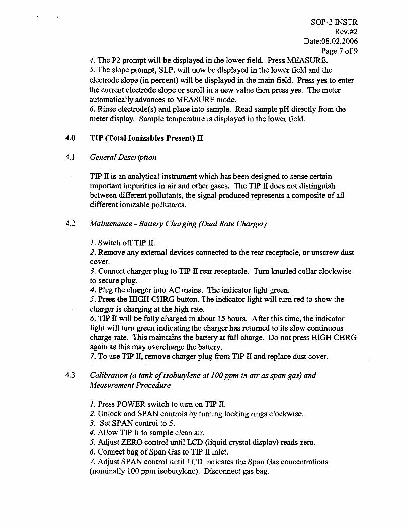
SOP-2 INSTR Rev.#2
Date:08.02.2006 Page 70f9
4. The P2 prompt will be displayed in the lower field. Press MEASURE. 5. The slope prompt, SLP~ will now be displayed in the lower field and the electrode slope (in percent) will be displayed in the main field. Press yes to enter the current electrode slope or scroll in a new value then press yes. The meter automatically advances to MEASURE mode. 6. Rinse electrode(s) and place into sample. Read sample pH directly from the meter display. Sample temperature is displayed in the lower field.
4.0 TIP (Total Ionizables Present) II
4.1 General Description
TIP IT is an analytical instrument which has been designed to sense certain important impurities in air and other gases. The TIP IT does not distinguish between different pollutants, the signal produced represents a composite of all different ionizable pollutants.
4.2 Maintenance - Battery Charging (Dual Rate Charger)
1. Switch off TIP II. 2. Remove any external devices connected to the rear receptacle, or unscrew dust cover. 3. Connect charger plug to TIP II rear receptacle. Turn knurled collar clockwise to secure plug. 4. Plug the charger into AC mains. The indicator light green. 5. Press the HIGH CHRG button. The indicator light will turn red to show the charger is charging at the high rate. 6. TIP II will be fully charged in about 15 hours. After this time, the indicator light will turn green indicating the charger has returned to its slow continuous charge rate. This maintains the battery at full charge. Do not press HIGH CHRG again as this may overcharge the battery. 7. To use TIP II, remove charger plug from TIP II and replace dust cover.
4.3 Calibration (a tank of isobutylene at 100 ppm in air as span gas) and Measurement Procedure
1. Press POWER switch to turn on TIP II. 2. Unlock and SPAN controls by turning locking rings clockwise. 3. Set SPAN controlto 5. 4. Allow TIP II to sample clean air. 5. Adjust ZERO control until LCD (liquid crystal display) reads zero. 6. Connect bag of Span Gas to TIP II inlet. 7. Adjust SPAN control until LCD indicates the Span Gas concentrations (nominally 100 ppm isobutylene). Disconnect gas bag.
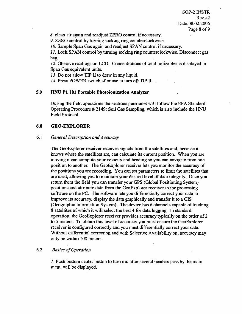
· SOP-2 INSTR
8. clean air again and readjust ZERO control if necessary. 9. ZERO control by turning locking ring counterclockwise.
Rev.#2 Date:08.02.2006
Page 8 of9
10. Sample Span Gas again and readjust SPAN control if necessary. 11. Lock SPAN control by turning locking ring counterclockwise. Disconnect gas bag. 12. Observe readings on LCD. Concentrations of total ionizables is displayed in Span Gas equivalent units. 13. Do not allow TIP IT to draw in any liquid. 14. Press POWER switch after use to turn off TIP II.
5.0 HNU PI 101 Portable Photoionization Analyzer
During the field operations the sections personnel will follow the EPA Standard Operating Procedure # 2149: Soil Gas Sampling, which is also include the HNU Field Protocol.
6.0 GEO-EXPLORER
6.1 General Description and Accuracy
The GeoExplorer receiver receives signals from the satellites and, because it knows where the satellites are, can calculate its current position. When you are moving it can compute your velocity and heading so you can navigate from one position to another. The GeoExplorer receiver lets you monitor the accuracy of the positions you are recording. You can set parameters to limit the satellites that are used, allowing you to maintain your desired level of data integrity. Once you return from the field you can transfer your GPS (Global Positioning System) positions and attribute data from the GeoExplorer receiver to the processing software on the PC. The software lets you differentially correct your data to improve.its accuracy, display the data graphically and transfer it to a GIS (Geographic Information System). The device has 6 channels capable of tracking 8 satellites of which it will select the best 4 for data logging. In standard operation, the GeoExplorer receiver provides accuracy typically on the order of 2 to 5 meters. To obtain this level of accuracy you must ensure the GeoExplorer receiver is configured correctly and you must differentially correct your data. Without differential correction and with Selective Availability on, accuracy may only be within 100 meters.
6.2 Basics of Operation
1. Push bottom center button to turn on; after several headers pass by the main menu will be displayed.
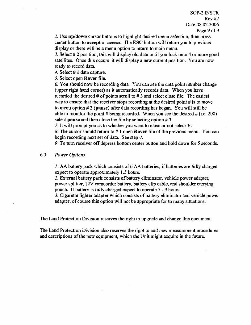
SOP-2 INSTR Rev.#2
Date:08.02.2006 Page 9 of9
2. Use up/down cursor buttons to highlight desired menu selection; then press center button to accept or access. The ESC button will return you to previous display or there will be a menu option to return to main menu. 3. Select # 2 position; this will display old data until you lock onto 4 or more good satellites. Once this occurs it will display a new current position. You are now ready to record data. 4. Select # 1 data capture. 5. Select open Rover file. 6. You should now be recording data. You can see the data point number change (upper right hand comer) as it automatically records data. When you have recorded the desired # of points scroll to # 3 and select close file. The easiest way to ensure that the receiver stops recording at the desired point # is to move to menu option # 2 (pause) after data recording has began. You will still be able to monitor the point # being recorded. When you see the desired # (i.e. 200) select pause and then close the file by selecting option # 3. 7. It will prompt you as to whether you want to close or not select Y. 8. The cursor should return to # 1 open Rover file of the previous menu. You can begin recording next set of data. See step 4. 9. To tum receiver off depress bottom center button and hold down for 5 seconds.
6.3 Power Options
1. AA battery pack which consists of 6 AA batteries, if batteries are fully charged expect to operate approximately 1.5 hours. 2. External battery pack consists of battery eliminator, vehicle power adapter. power splitter, 12V camcorder battery, battery clip cable, and shoulder carrying pouch. If battery is fully charged expect to operate 7 - 9 hours. 3. Cigarette lighter adapter which consists of battery eliminator and vehicle power adapter, of course this option will not be appropriate for to many situations.
The Land Protection Division reserves the right to upgrade and change this document.
The Land Protection Division also reserves the right to add new measurement procedures and descriptions of the new equipment, which the Unit might acquire in the future.
Standard Operating Procedure (SOP)
Subsurface Soil and Bedrock Sampling
SOP-4 SOIL Rev.#2
Date: 11.08.2006 Page 1 of6

Approval Page
SOP-4 SOIL Rev.#2
Date: 11.08.2006 Page 2 of6
Prepared by: ____ ...... ~"--~~+rLd.t ~~~ ____ _ ~ill5i7oFn
Date: _, '-+-/~~I C1!..._
Approved by:
QA Coordinator
4 ~ ~ ~.. . . Date: I<:eii§ Dixon
Environmental Programs Manager
/III i/O ~ ,- ,
Approved by: ____ .J<:U_· _""_.:._;_" ---'h:.....,.t.~~~..::::=:.. ___ _ AmiILyr')",;
Date: _1_1-,--/9.;..:...fi..:..L.o k_
Environmental Programs Manager
Approved by:----"j~~t'~ A~-. __ ~ Date: u/rIo , Brownfields Program Manager
Approved by: --\""c-= /J--,. ~~i..:::..(L---I~'r:· f'-I-'{,1'-"'A1~4H'} /M<JL'-"'~=--"'--LLM--J AngclaBrunsman Environmental Programs Manager
Date: II / /3/ Db I '
APProvedbY:~~ ~~ QA Officer
~ APprOvedbY:~~r-~~ __ ~ _______ _ Scott Thompson
Date:
Land Protection Division Director
Site Remediation Section Voluntary Cleanup & Brownfields Section
Land Protection Division Oklahoma DEQ
I/-I:?' 06
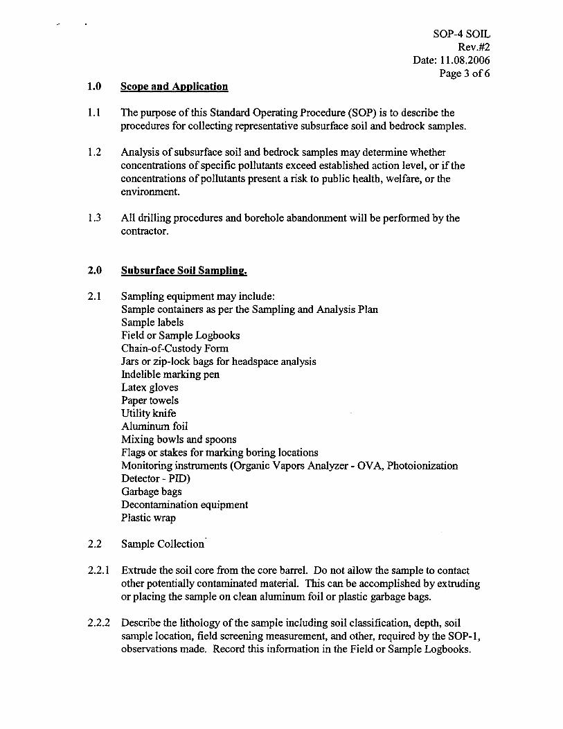
1.0 Scope and Application
SOP-4 SOIL Rev.#2
Date: 11.08.2006 Page 3 of6
1.1 The purpose of this Standard Operating Procedure (SOP) is to describe the procedures for collecting representative subsurface soil and bedrock samples.
1.2 Analysis of subsurface soil and bedrock samples may determine whether concentrations of specific pollutants exceed established action level, or if the concentrations of pollutants present a risk to public health, welfare, or the environment.
1.3 All drilling procedures and borehole abandonment will be performed by the contractor.
2.0 Subsurface Soil Sampling.
2.1 Sampling equipment may include: Sample containers as per the Sampling and Analysis Plan Sample labels Field or Sample Logbooks Chain-of-Custody Form Jars or zip-lock bags for headspace analysis Indelible marking pen Latex gloves Paper towels Utility knife Aluminum foil Mixing bowls and spoons Flags or stakes for marking boring locations Monitoring instruments (Organic Vapors Analyzer - OVA, Photoionization Detector - PID) Garbage bags Decontamination equipment Plastic wrap
2.2 Sample Collection'
2.2.1 Extrude the soil core from the core barrel. Do not allow the sample to contact other potentially contaminated material. This can be accomplished by extruding or placing the sample on clean aluminum foil or plastic garbage bags.
2.2.2 Describe the lithology of the sample including soil classification, depth, soil sample location, field screening measurement, and other, required by the SOP-I, observations made. Record this information in the Field or Sample Logbooks.
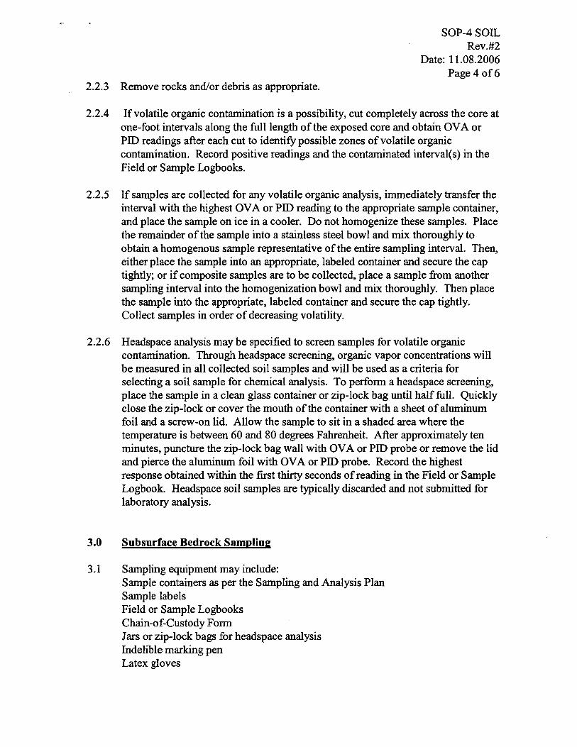
2.2.3 Remove rocks and/or debris as appropriate.
SOP-4 SOIL Rev.#2
Date: 11.08.2006 Page 4 of6
2.2.4 If volatile organic contamination is a possibility, cut completely across the core at one-foot intervals along the full length of the exposed core and obtain OVA or PID readings after each cut to identify possible zones of volatile organic contamination. Record positive readings and the contaminated interval(s) in the Field or Sample Logbooks.
2.2.5 If samples are collected for any volatile organic analysis, immediately transfer the interval with the highest OV A or PID reading to the appropriate sample container, and place the sample on ice in a cooler. Do not homogenize these samples. Place the remainder ofthe sample into a stainless steel bowl and mix thoroughly to obtain a homogenous sample representative of the entire sampling interval. Then, either place the sample into an appropriate, labeled container and secure the cap tightly; or if composite samples are to be collected, place a sample from another sampling interval into the homogenization bowl and mix thoroughly. Then place the sample into the appropriate, labeled container and secure the cap tightly. Collect samples in order of decreasing volatility.
2.2.6 Headspace analysis may be specified to screen samples for volatile organic contamination. Through headspace screening, organic vapor concentrations will be measured in all collected soil samples and will be used as a criteria for selecting a soil sample for chemical analysis. To perform a headspace screening, place the sample in a clean glass container or zip-lock bag until half full. Quickly close the zip-lock or cover the mouth of the container with a sheet of aluminum foil and a screw-on lid. Allow the sample to sit in a shaded area where the temperature is between 60 and 80 degrees Fahrenheit. After approximately ten minutes, puncture the zip-lock bag wall with OVA or PID probe or remove the lid and pierce the aluminum foil with OVA or PID probe. Record the highest response obtained within the first thirty seconds of reading in the Field or Sample Logbook. Headspace soil samples are typically discarded and not submitted for laboratory analysis.
3.0 Subsurface Bedrock Sampling
3.1 Sampling equipment may include: Sample containers as per the Sampling and Analysis Plan Sample labels Field or Sample Logbooks Chain-of-Custody Form Jars or zip-lock bags for headspace analysis Indelible marking pen Latex gloves
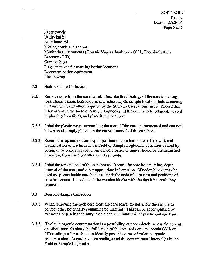
Paper towels Utility knife Aluminum foil Mixing bowls and spoons
SOP-4 SOIL Rev.#2
Date: 11.08.2006 Page 5 of6
Monitoring instruments (Organic Vapors Analyzer - OVA, Photoionization Detector - PID) Garbage bags Flags or stakes for marking boring locations Decontamination equipment Plastic wrap
3.2 Bedrock Core Collection
3.2.1 Remove core from the core barrel. Describe the lithology of the core including rock classification, bedrock characteristics, depth. sample location, field screening measurement, and other. required by the SOP-I, observations made. Record this information in the Field or Sample Logbooks. If the core is to be retained, wrap it in plastic (if possible), and place it in a core box.
3.2.2 Label the plastic wrap surrounding the core. If the core is fragmented and can not be wrapped, simply place it in the correct interval of the core box.
3.2.3 Record the top and bottom depth, position of core loss zones (if known), and identification of fractures in the Field or Sample Logbooks. Fractures caused by coring or by removing core from the core barrel or auger should be distinguished in writing from fractures interpreted as in-situ.
3.2.4 Label the top and end of the core boxes. Record the core hole number, depth interval of the core, and other appropriate information. Wooden blocks may be used as spacers inside core boxes to mark the ends of core runs and positions of core loss zones. If used. label the wooden blocks with the depth intervals they represent.
3.3 Bedrock Sample Collection
3.3.1 When removing the rock core from the core barrel do not allow the sample to contact other potentially contaminated material. This can be accomplished by extruding or placing the sample on clean aluminum foil or plastic garbage bags.
3.3.2 If volatile organic contamination is a possibility, cut completely across the core at one-foot intervals along the full length of the exposed core and obtain OVA or PID readings after each cut to identify possible zones of volatile organic contamination. Record positive readings and the contaminated interval(s) in the Field or Sample Logbooks.

SOP-4 SOIL Rev.#2
Date: 11.08.2006 Page 6 of6
3.3.3 If samples are collected for any volatile organic analysis, immediately transfer the interval with the highest OV A or PID reading to the appropriate sample container, and place the sample on ice in a cooler. Do not homogenize these samples. Place the remainder of the sample into a stainless steel bowl and mix thoroughly to obtain a homogenous sample representative of the entire sampling interval. Then, either place the sample into an appropriate, labeled container and secure the cap tightly; or if composite samples are to be collected, place a sample from another sampling interval into the homogenization bowl and mix thoroughly. Then place the sample into the appropriate, labeled container and secure the cap tightly. Collect samples in order of decreasing volatility.
3.3.4 Headspace analysis may be specified to screen samples for volatile organic contamination. Through headspace screening, organic vapor concentrations will be measured in all collected soil samples and will be used as a criteria for selecting a soil sample for chemical analysis. To perform a headspace screening, place the sample in a clean glass container or zip-lock bag until half full. Quickly close the zip-lock or cover the mouth of the container with a sheet of aluminum foil and a screw-on lid. Allow the sample to sit in a shaded area where the temperature is between 60 and 80 degrees Fahrenheit. After approximately ten minutes, puncture the zip-lock bag wall with OVA or PID probe or remove the lid and pierce the aluminum foil with OV A or PID probe. Record the highest response obtained within the first thirty seconds of reading in the Field or Sample Logbook. Headspace soil samples are typically discarded and not submitted for laboratory analysis.
Sampling equipment decontamination will be performed in accordance with EPA SOP # 2006.
The Land Protection Division reserves the right to change this document.

Standard Operating Procedure (SOP) SOP-S
Surface Water Sampling
Prepared and Approved by: -'='::=;;LJ~":"':-''''''':-''':::''::.-..!.-~~------Karen Khala tan DEQ QA Officer
Approved by: --~.s..,,~= . ..y.= .... ' ~:::....-_--~+--. ....;L/,,-==--. -==:..-_/_) Date: Keil;d5ixon
Environmental Programs Manager
Date: )
SOP-5 SW Rev.#l
Date: 05.22.2006 Page 1 of3
Date: ,I '- -.? Z - 0 b
Approved by: ____ I '_-.-:..1 __ '_-....,' _' --'"-=-___ _ ------Amil Ly~li
Environmental Programs Manager
Approved by: ____ ,_{r_~r_....;·-_· _/:_:'_~_-------__ -__ ---_-'_-'_ Scott Thompson
Land Protection Division Director
Site Remediation Section Voluntary Cleanup & Brownfields Section
Land Protection Division Oklahoma DEQ

1.0 Scope and Application
SOp-s sw Rev.#l
Date: OS.22.2006 Page 2 of3
1.1 Site Remediation Section and Voluntary Cleanup & Brownfields Section of the Land Protection Division follow the EPA 2.0 Surface Water Sampling: SOP # 2013. Sample collection is conducted in a full accordance with the methods described in the SOP # 2013.
1.2 The purpose of this Standard Operating Procedure (SOP-S) is to describe the procedures for collecting representative liquid samples, both aqueous and nonaqueous from streams, rivers, lakes, and ponds when using pre-preserved sample containers prepared to be shipped to CLP Laboratories.
1.3 This document is prepared to address only sampling limited to the above mentioned surface water bodies and will not be used for sampling lagoons or other impoundments w~ere contact with contaminants are a concern.
1.4 Sample preservation, containers, handling, storage, QNQC, data validation, and health and safety issues are discussed in the EPA SOP # 2013 and will be followed by LPD personnel during all types of surface water sampling.
2.0 Surface Water Samplina..
2.1 Sampling equipment may include: Sample containers as per the Sampling and Analysis Plan Pre-decontaminated sample bottles Sample labels Sample tags Field or Sample Logbooks Chain-of-Custody Fonn Jars or zip-lock bags Packing foam and tape Ice and coolers Indelible marking pen Latex gloves Paper towels Utility knife Spray bottles (with DI water) Tyvec suits Cameras GPS unit Monitoring instruments (Organic Vapors Analyzer - OVA, Photoionization Detector - PID, pH, conductivity and temperature meter, flow meter) Garbage bags Decontamination equipment
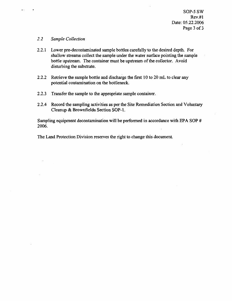
2.2 Sample Collection
SOP-5 SW Rev.#1
Date: 05.22.2006 Page 3 of3
2.2.1 Lower pre-decontaminated sample bottles carefully to the desired depth. For shallow streams collect the sample under the water surface pointing the sample bottle upstream. The container must be upstream of the collector. Avoid disturbing the substrate.
2.2.2 Retrieve the sample bottle and discharge the fIrst 10 to 20 mL to clear any potential contamination on the bottleneck.
2.2.3 Transfer the sample to the appropriate sample container.
2.2.4 Record the sampling activities as per the Site Remediation Section and Voluntary Cleanup & BrownfIelds Section SOP-I.
Sampling equipment decontamination will be performed in accordance with EPA SOP # 2006.
The Land Protection Division reserves the right to change this document.

Standard Operating Procedure (SOP)
SOP-7
SOP-7 GW Low-Flow Rev. #0
Date: 12.19.2007 Page 1 of 3
Monitoring Well Sampling with a Low-Flow Peristaltic Pump
Prepared by: ~ ~ Amy nttam Environment Programs Specialist
Approved by: 4 k.,' VeL Subi John I Superfund QA Officer
Approved by: -;;~~~:s;;;::;;;;:-d~::::::::::::=-:=?~=---~( Remediation Unit Manager
~~/;f~ Approvedby: ___ ~~~ ________________________ _
Scott Thompson Land Protection Division Director
APProVedb4~-Karen alafian ;V
DEQ QA Officer
Remediation Unit Land Protection Division
Date:l2...- (q -0 /
Date: 12 - 17- 0 ?---------
Date: /2.-2(-0/>
Oklahoma Department of Environmental Quality
1.0 Scope and Application
SOP-7 GW Low-Flow Rev. #0
Date: 12.19.2007 Page 2 of 3
1.1 The Remediation Unit, which includes the Site Remediation, Voluntary Cleanup, Brownfields, and Tar Creek Sections, of the Land Protection Division follow the EPA 2.0 Groundwater Well Sampling: SOP # 2007. Sample collection is conducted in full accordance with SOP # 2007.
1.2 The purpose of this Standard Operating Procedure (SOP-6) is to describe the procedures for collecting representative ground water samples from monitoring wells with a low-flow peristaltic pump.
1.3 Sample preservation, containers, handling, storage, QC samples, data validation, and health and safety issues are discussed in the EPA SOP # 2007 and will be followed by LPD personnel during all types of ground water sampling.
2.0 Ground Water Sampling
2.1 Sampling equipment may include: Sample containers as per the Sampling and Analysis Plan Pre-decontaminated sample bottles Sample labels Sample tags Field or Sample Logbooks Chain-of-Custody Form Jars and bottles Zip-lock bags Packing foam and tape Ice and coolers Indelible marking pen Latex gloves Paper towels Utility knife Spray bottles (with DI water) Tyvec suits Cameras GPS unit Monitoring instruments (Organic Vapors Analyzer -OV A, Photoinization Detector - PID, pH, conductivity and temperature meter, chemical field test kits) Peristaltic Pump Flow-through cell Polyethylene tubing Bailers Garbage bags Decontamination equipment

2.2 Sample Collection
2.2.1 Use dedicated tubing in each well.
SOP-7 OW Low-Flow Rev. #0
Date: 12.19.2007 Page 3 of 3
2.2.2 Maintain the same or slightly reduced pumping rate as used during well purging throughout sample collection in order to minimize disturbance of the water column.
2.2.3 Collect samples directly from the discharge port of the pump tubing prior to passing through the flow-through cell. Disconnect the pump's tubing from the flow-through cell.
2.2.4 Fill all sample containers with minimal turbulence by allowing the ground water to flow from the tubing gently down the inside of the container.
2.2.5 Fill sample containers in the order specified in the project Sampling and Analysis Plan and Quality Assurance Project Plan. Fill the VOC samples so that a meniscus is formed over the mouth of the vial to eliminate the fontlation of air bubbles and head space prior to capping.
2.2.4 Collect filtered samples last. If filtered metal samples are to be collected, then attach the in-line filter to the end of the discharge tubing and collect the sample from the filter discharge.
2.2.6 Record the sampling activities as per the Site Remediation Section and Voluntary Cleanup & Brownfields Section SOP-I.
Sampling equipment decontamination will be performed in accordance with EPA SOP # 2006.
The Land Protection Division reserves the right to change this document.
1
SOP#: 2006DATE: 08/11/94
REV. #: 0.0
SAMPLING EQUIPMENTDECONTAMINATION
1.0 SCOPE AND APPLICATION
The purpose of this Standard Operating Procedure(SOP) is to provide a description of the methods usedfor preventing, minimizing, or limitingcross-contamination of samples due to inappropriateor inadequate equipment decontamination and toprovide general guidelines for developingdecontamination procedures for sampling equipmentto be used during hazardous waste operations as per29 Code of Federal Regulations (CFR) 1910.120.This SOP does not address personneldecontamination.
These are standard (i.e. typically applicable) operatingprocedures which may be varied or changed asrequired, dependent upon site conditions, equipmentlimitation, or limitations imposed by the procedure.In all instances, the ultimate procedures employedshould be documented and associated with the finalreport.
Mention of trade names or commercial products doesnot constitute U.S. Environmental Protection Agency(U.S. EPA) endorsement or recommendation for use.
2.0 METHOD SUMMARY
Removing or neutralizing contaminants fromequipment minimizes the likelihood of sample crosscontamination, reduces or eliminates transfer ofcontaminants to clean areas, and prevents the mixingof incompatible substances.
Gross contamination can be removed by physicaldecontamination procedures. These abrasive andnon-abrasive methods include the use of brushes, airand wet blasting, and high and low pressure watercleaning.
The first step, a soap and water wash, removes al lvisible particulate matter and residual oils and grease.This may be preceded by a steam or high pressure
water wash to facilitate residuals removal. Thesecond step involves a tap water rinse and adistilled/deionized water rinse to remove thedetergent. An acid rinse provides a low pH media fortrace metals removal and is included in thedecontamination process if metal samples are to becollected. It is followed by another distilled/deionizedwater rinse. If sample analysis does not includemetals, the acid rinse step can be omitted. Next, ahigh purity solvent rinse is performed for traceorganics removal if organics are a concern at the site.Typical solvents used for removal of organiccontaminants include acetone, hexane, or water.Acetone is typically chosen because it is an excellentsolvent, miscible in water, and not a target analyte onthe Priority Pollutant List. If acetone is known to bea contaminant of concern at a given site or if TargetCompound List analysis (which includes acetone) isto be performed, another solvent may be substituted.The solvent must be allowed to evaporate completelyand then a final distilled/deionized water rinse isperformed. This rinse removes any residual traces ofthe solvent.
The decontamination procedure described above maybe summarized as follows:
1. Physical removal2. Non-phosphate detergent wash3. Tap water rinse4. Distilled/deionized water rinse5. 10% nitric acid rinse6. Distilled/deionized water rinse7. Solvent rinse (pesticide grade)8. Air dry9. Distilled/deionized water rinse
If a particular contaminant fraction is not present atthe site, the nine (9) step decontamination procedurespecified above may be modified for site specificity.For example, the nitric acid rinse may be eliminatedif metals are not of concern at a site. Similarly, thesolvent rinse may be eliminated if organics are not of

2
concern at a site. Modifications to the standard bristle scrub brushes or long-handled bottle brushesprocedure should be documented in the site specific can be used to remove contaminants. Largework plan or subsequent report. galvanized wash tubs, stock tanks, or buckets can hold
3.0 SAMPLE PRESERVATION,CONTAINERS, HANDLING,AND STORAGE
The amount of sample to be collected and the propersample container type (i.e., glass, plastic), chemicalpreservation, and storage requirements are dependenton the matrix being sampled and the parameter(s) ofinterest. More specifically, sample collection and analysis ofdecontamination waste may be required beforebeginning proper disposal of decontamination liquidsand solids generated at a site. This should bedetermined prior to initiation of site activities.
4.0 INTERFERENCES ANDPOTENTIAL PROBLEMS
C The use of distilled/deionized watercommonly available from commercialvendors may be acceptable fordecontamination of sampling equipmentprovided that it has been verified bylaboratory analysis to be analyte free(specifically for the contaminants ofconcern).
C The use of an untreated potable water supplyis not an acceptable substitute for tap water.Tap water may be used from any municipalor industrial water treatment system.
C If acids or solvents are utilized indecontamination they raise health and safety,and waste disposal concerns.
C Damage can be incurred by acid and solventwashing of complex and sophisticatedsampling equipment.
5.0 EQUIPMENT/APPARATUS
Decontamination equipment, materials, and suppliesare generally selected based on availability. Otherconsiderations include the ease of decontaminating ordisposing of the equipment. Most equipment andsupplies can be easily procured. For example, soft-
wash and rinse solutions. Children's wading pools canalso be used. Large plastic garbage cans or othersimilar containers lined with plastic bags can helpsegregate contaminated equipment. Contaminatedliquid can be stored temporarily in metal or plasticcans or drums.
The following standard materials and equipment arerecommended for decontamination activities:
5.1 Decontamination Solutions
C Non-phosphate detergentC Selected solvents (acetone, hexane, nitric
acid, etc.)C Tap waterC Distilled or deionized water
5.2 Decontamination Tools/Supplies
C Long and short handled brushesC Bottle brushesC Drop cloth/plastic sheetingC Paper towelsC Plastic or galvanized tubs or bucketsC Pressurized sprayers (H O)2
C Solvent sprayersC Aluminum foil
5.3 Health and Safety Equipment
Appropriate personal protective equipment (i.e., safetyglasses or splash shield, appropriate gloves, aprons orcoveralls, respirator, emergency eye wash)
5.4 Waste Disposal
C Trash bagsC Trash containersC 55-gallon drumsC Metal/plastic buckets/containers for storage
and disposal of decontamination solutions
6.0 REAGENTS
There are no reagents used in this procedure asidefrom the actual decontamination solutions. Table 1(Appendix A) lists solvent rinses which may berequired for elimination of particular chemicals. In
3
general, the following solvents are typically utilized contaminants by neutralization, chemical reaction,for decontamination purposes: disinfection, or sterilization.
C 10% nitric acid is typically used for Physical decontamination techniques can be groupedinorganic compounds such as metals. An into two categories: abrasive methods andacid rinse may not be required if inorganics non-abrasive methods, as follows:are not a contaminant of concern.
C Acetone (pesticide grade)(1)
C Hexane (pesticide grade)(1)
C Methanol(1)
- Only if sample is to be analyzed for organics.(1)
7.0 PROCEDURES
As part of the health and safety plan, adecontamination plan should be developed andreviewed. The decontamination line should be set upbefore any personnel or equipment enter the areas ofpotential exposure. The equipment decontaminationplan should include:
C The number, location, and layout ofdecontamination stations.
C Decontamination equipment needed.
C Appropriate decontamination methods.
C Methods for disposal of contaminatedclothing, equipment, and solutions.
C Procedures can be established to minimizethe potential for contamination. This mayinclude: (1) work practices that minimizecontact with potential contaminants; (2)using remote sampling techniques; (3)covering monitoring and sampling equipmentwith plastic, aluminum foil, or otherprotective material; (4) watering down dustyareas; (5) avoiding laying down equipment inareas of obvious contamination; and (6) useof disposable sampling equipment.
7.1 Decontamination Methods
All samples and equipment leaving the contaminatedarea of a site must be decontaminated to remove anycontamination that may have adhered to equipment.Various decontamination methods will removecontaminants by: (1) flushing or other physicalaction, or (2) chemical complexing to inactivate
7.1.1 Abrasive Cleaning Methods
Abrasive cleaning methods work by rubbing andwearing away the top layer of the surface containingthe contaminant. The mechanical abrasive cleaningmethods are most commonly used at hazardous wastesites. The following abrasive methods are available:
Mechanical
Mechanical methods of decontamination include usingmetal or nylon brushes. The amount and type ofcontaminants removed will vary with the hardness ofbristles, length of time brushed, degree of brushcontact, degree of contamination, nature of the surfacebeing cleaned, and degree of contaminant adherenceto the surface.
Air Blasting
Air blasting equipment uses compressed air to forceabrasive material through a nozzle at high velocities.The distance between nozzle and surface cleaned, airpressure, time of application, and angle at which theabrasive strikes the surface will dictate cleaningefficiency. Disadvantages of this method are theinability to control the amount of material removedand the large amount of waste generated.
Wet Blasting
Wet blast cleaning involves use of a suspended fineabrasive. The abrasive/water mixture is delivered bycompressed air to the contaminated area. By using avery fine abrasive, the amount of materials removedcan be carefully controlled.
7.1.2 Non-Abrasive Cleaning Methods
Non-abrasive cleaning methods work by forcing thecontaminant off a surface with pressure. In general,the equipment surface is not removed usingnon-abrasive methods.

4
Low-Pressure Water
This method consists of a container which is filledwith water. The user pumps air out of the container tocreate a vacuum. A slender nozzle and hose allow theuser to spray in hard-to-reach places.
High-Pressure Water
This method consists of a high-pressure pump, anoperator controlled directional nozzle, and a high-pressure hose. Operating pressure usually rangesfrom 340 to 680 atmospheres (atm) and flow ratesusually range from 20 to 140 liters per minute.
Ultra-High-Pressure Water
This system produces a water jet that is pressuredfrom 1,000 to 4,000 atmospheres. Thisultra-high-pressure spray can remove tightly-adheredsurface films. The water velocity ranges from 500meters/second (m/s) (1,000 atm) to 900 m/s (4,000atm). Additives can be used to enhance the cleaningaction.
Rinsing
Contaminants are removed by rinsing throughdilution, physical attraction, and solubilization.
Damp Cloth Removal
In some instances, due to sensitive, non-waterproofequipment or due to the unlikelihood of equipmentbeing contaminated, it is not necessary to conduct anextensive decontamination procedure. For example,air sampling pumps hooked on a fence, placed on adrum, or wrapped in plastic bags are not likely tobecome heavily contaminated. A damp cloth shouldbe used to wipe off contaminants which may haveadhered to equipment through airborne contaminantsor from surfaces upon which the equipment was set .
Disinfection/Sterilization
Disinfectants are a practical means of inactivatinginfectious agents. Unfortunately, standardsterilization methods are impractical for largeequipment. This method of decontamination istypically performed off-site.
7.2 Field Sampling EquipmentDecontamination Procedures
The decontamination line is setup so that the firststation is used to clean the most contaminated item.It progresses to the last station where the leastcontaminated item is cleaned. The spread ofcontaminants is further reduced by separating eachdecontamination station by a minimum of three (3)feet. Ideally, the contamination should decrease as theequipment progresses from one station to anotherfarther along in the line.
A site is typically divided up into the followingboundaries: Hot Zone or Exclusion Zone (EZ), theContamination Reduction Zone (CRZ), and theSupport or Safe Zone (SZ). The decontamination lineshould be setup in the Contamination ReductionCorridor (CRC) which is in the CRZ. Figure 1(Appendix B) shows a typical contaminant reductionzone layout. The CRC controls access into and out ofthe exclusion zone and confines decontaminationactivities to a limited area. The CRC boundariesshould be conspicuously marked. The far end is thehotline, the boundary between the exclusion zone andthe contamination reduction zone. The size of thedecontamination corridor depends on the number ofstations in the decontamination process, overalldimensions of the work zones, and amount of spaceavailable at the site. Whenever possible, it should bea straight line.
Anyone in the CRC should be wearing the level ofprotection designated for the decontamination crew.Another corridor may be required for the entry andexit of heavy equipment. Sampling and monitoringequipment and sampling supplies are all maintainedoutside of the CRC. Personnel don their equipmentaway from the CRC and enter the exclusion zonethrough a separate access control point at the hotline.One person (or more) dedicated to decontaminatingequipment is recommended.
7.2.1 Decontamination Setup
Starting with the most contaminated station, thedecontamination setup should be as follows:
Station 1: Segregate Equipment Drop
Place plastic sheeting on the ground (Figure 2,Appendix B). Size will depend on amount of
5
equipment to be decontaminated. Provide containers pool with tap water. Several bottle and bristle brusheslined with plastic if equipment is to be segregated. should be dedicated to this station. ApproximatelySegregation may be required if sensitive equipment or 10-50 gallons of water may be required initiallymildly contaminated equipment is used at the same depending upon the amount of equipment totime as equipment which is likely to be heavily decontaminate and the amount of gross contamination.contaminated.
Station 2: Physical Removal With A High-PressureWasher (Optional) Fill a low-pressure sprayer with distilled/deionized
As indicated in 7.1.2, a high-pressure wash may be the water during the rinsing process. Approximatelyrequired for compounds which are difficult to remove 10-20 gallons of water may be required initiallyby washing with brushes. The elevated temperature of depending upon the amount of equipment tothe water from the high-pressure washers is excellent decontaminate and the amount of gross contamination.at removing greasy/oily compounds. High pressurewashers require water and electricity. Station 6: Nitric Acid Sprayers
A decontamination pad may be required for the high- Fill a spray bottle with 10% nitric acid. An acid rinsepressure wash area. An example of a wash pad may may not be required if inorganics are not aconsist of an approximately 1 1/2 foot-deep basin contaminant of concern. The amount of acid willlined with plastic sheeting and sloped to a sump at one depend on the amount of equipment to becorner. A layer of sand can be placed over the plastic decontaminated. Provide a 5-gallon bucket or basin toand the basin is filled with gravel or shell. The sump collect acid during the rinsing process.is also lined with visqueen and a barrel is placed in thehole to prevent collapse. A sump pump is used to Station 7: Low-Pressure Sprayersremove the water from the sump for transfer into adrum. Fill a low-pressure sprayer with distilled/deionized
Typically heavy machinery is decontaminated at the water during the rinsate process. end of the day unless site sampling requires that themachinery be decontaminated frequently. A separate Station 8: Organic Solvent Sprayersdecontamination pad may be required for heavyequipment. Fill a spray bottle with an organic solvent. After each
Station 3: Physical Removal With Brushes And A distilled/deionized water and air dried. Amount ofWash Basin solvent will depend on the amount of equipment to
Prior to setting up Station 3, place plastic sheeting on collect the solvent during the rinsing process. the ground to cover areas under Station 3 throughStation 10. Solvent rinses may not be required unless organics areFill a wash basin, a large bucket, or child's swimming a contaminant of concern, and may be eliminated frompool with non-phosphate detergent and tap water. the station sequence. Several bottle and bristle brushes to physically removecontamination should be dedicated to this station . Station 9: Low-Pressure SprayersApproximately 10 - 50 gallons of water may berequired initially depending upon the amount of Fill a low-pressure sprayer with distilled/deionizedequipment to decontaminate and the amount of gross water. Provide a 5-gallon bucket or basin to collectcontamination. water during the rinsate process.
Station 4: Water Basin Station 10: Clean Equipment Drop
Fill a wash basin, a large bucket, or child's swimming Lay a clean piece of plastic sheeting over the bottom
Station 5: Low-Pressure Sprayers
water. Provide a 5-gallon bucket or basin to contain
water. Provide a 5-gallon bucket or basin to collect
solvent rinse, the equipment should be rinsed with
decontaminate. Provide a 5-gallon bucket or basin to

6
plastic layer. This will allow easy removal of the Using a spray bottle rinse sampling equipment withplastic in the event that it becomes dirty. Provide nitric acid. Begin spraying (inside and outside) at onealuminum foil, plastic, or other protective material to end of the equipment allowing the acid to drip to thewrap clean equipment. other end into a 5-gallon bucket. A rinsate blank may
7.2.2 Decontamination Procedures
Station 1: Segregate Equipment Drop
Deposit equipment used on-site (i.e., tools, samplingdevices and containers, monitoring instruments radios,clipboards, etc.) on the plastic drop cloth/sheet or indifferent containers with plastic liners. Each will becontaminated to a different degree. Segregation at thedrop reduces the probability of cross contamination.Loose leaf sampling data sheets or maps can be placedin plastic zip lock bags if contamination is evident.
Station 2: Physical Removal With A High-PressureWasher (Optional)
Use high pressure wash on grossly contaminatedequipment. Do not use high- pressure wash onsensitive or non-waterproof equipment.
Station 3: Physical Removal With Brushes And AWash Basin
Scrub equipment with soap and water using bottle andbristle brushes. Only sensitive equipment (i.e., radios,air monitoring and sampling equipment) which iswaterproof should be washed. Equipment which isnot waterproof should have plastic bags removed andwiped down with a damp cloth. Acids and organicrinses may also ruin sensitive equipment. Consult the 1. Collect high-pressure pad and heavymanufacturers for recommended decontamination equipment decontamination area liquid andsolutions. waste and store in appropriate drum or
Station 4: Equipment Rinse collection process. Refer to the Department
Wash soap off of equipment with water by immersing appropriate containers based on thethe equipment in the water while brushing. Repeat as contaminant of concern.many times as necessary.
Station 5: Low-Pressure Rinse equipment decontamination area solid waste
Rinse sampling equipment with distilled/deionized Refer to the DOT requirements forwater with a low-pressure sprayer. appropriate containers based on the
Station 6: Nitric Acid Sprayers ( required only ifmetals are a contaminant of concern) 3. Empty soap and water liquid wastes from
be required at this station. Refer to Section 9.
Station 7: Low-Pressure Sprayers
Rinse sampling equipment with distilled/deionizedwater with a low-pressure sprayer.
Station 8: Organic Solvent Sprayers
Rinse sampling equipment with a solvent. Beginspraying (inside and outside) at one end of theequipment allowing the solvent to drip to the otherend into a 5-gallon bucket. Allow the solvent toevaporate from the equipment before going to the nextstation. A QC rinsate sample may be required at thisstation.
Station 9: Low-Pressure Sprayers
Rinse sampling equipment with distilled/deionizedwater with a low-pressure washer.
Station 10 : Clean Equipment Drop
Lay clean equipment on plastic sheeting. Once airdried, wrap sampling equipment with aluminum foil,plastic, or other protective material.
7.2.3 Post Decontamination Procedures
container. A sump pump can aid in the
of Transportation (DOT) requirements for
2. Collect high-pressure pad and heavy
and store in appropriate drum or container.
contaminant of concern.
basins and buckets and store in appropriate
7
drum or container. Refer to the DOT equipment to test for residual contamination. Therequirements for appropriate containers blank water is collected in sample containers forbased on the contaminant of concern. handling, shipment, and analysis. These samples are
4. Empty acid rinse waste and place in rinsate blank is used to assess cross contaminationappropriate container or neutralize with a brought about by improper decontaminationbase and place in appropriate drum. pH procedures. Where dedicated sampling equipment ispaper or an equivalent pH test is required for not utilized, collect one rinsate blank per day per typeneutralization. Consult DOT requirements of sampling device samples to meet QA2 and QA3for appropriate drum for acid rinse waste. objectives.
5. Empty solvent rinse sprayer and solvent If sampling equipment requires the use of plasticwaste into an appropriate container. Consult tubing it should be disposed of as contaminated andDOT requirements for appropriate drum for replaced with clean tubing before additional samplingsolvent rinse waste. occurs.
6. Using low-pressure sprayers, rinse basins,and brushes. Place liquid generated fromthis process into the wash water rinsecontainer.
7. Empty low-pressure sprayer water onto theground.
8. Place all solid waste materials generatedfrom the decontamination area (i.e., glovesand plastic sheeting, etc.) in an approvedDOT drum. Refer to the DOT requirementsfor appropriate containers based on thecontaminant of concern.
9. Write appropriate labels for waste and makearrangements for disposal. Consult DOTregulations for the appropriate label for eachdrum generated from the decontaminationprocess.
8.0 CALCULATIONS
This section is not applicable to this SOP.
9.0 QUALITYASSURANCE/QUALITY CONTROL
A rinsate blank is one specific type of quality control substitutions should be made to eliminate the hazard.sample associated with the field decontamination The choice of respiratory protection based onprocess. This sample will provide information on the contaminants of concern from the site may not beeffectiveness of the decontamination process appropriate for solvents used in the decontaminationemployed in the field. process.
Rinsate blanks are samples obtained by running Safety considerations should be addressed when usinganalyte free water over decontaminated sampling abrasive and non-abrasive decontamination
treated identical to samples collected that day. A
10.0 DATA VALIDATION
Results of quality control samples will be evaluatedfor contamination. This information will be utilizedto qualify the environmental sample results inaccordance with the project's data quality objectives.
11.0 HEALTH AND SAFETY
When working with potentially hazardous materials ,follow OSHA, U.S. EPA, corporate, and otherapplicable health and safety procedures.
Decontamination can pose hazards under certaincircumstances. Hazardous substances may beincompatible with decontamination materials. Forexample, the decontamination solution may react withcontaminants to produce heat, explosion, or toxicproducts. Also, vapors from decontaminationsolutions may pose a direct health hazard to workersby inhalation, contact, fire, or explosion.
The decontamination solutions must be determined tobe acceptable before use. Decontamination materialsmay degrade protective clothing or equipment; somesolvents can permeate protective clothing. Ifdecontamination materials do pose a health hazard,measures should be taken to protect personnel or
8
equipment. Maximum air pressure produced byabrasive equipment could cause physical injury.Displaced material requires control mechanisms.
Material generated from decontamination activitiesrequires proper handling, storage, and disposal.Personal Protective Equipment may be required forthese activities.
Material safety data sheets are required for alldecontamination solvents or solutions as required bythe Hazard Communication Standard (i.e., acetone,alcohol, and trisodiumphosphate).
In some jurisdictions, phosphate containing detergents(i.e., TSP) are banned.
12.0 REFERENCES
Field Sampling Procedures Manual, New JerseyDepartment of Environmental Protection, February,1988.
A Compendium of Superfund Field OperationsMethods, EPA 540/p-87/001.
Engineering Support Branch Standard OperatingProcedures and Quality Assurance Manual, USEPARegion IV, April 1, 1986.
Guidelines for the Selection of Chemical ProtectiveClothing, Volume 1, Third Edition, AmericanConference of Governmental Industrial Hygienists,Inc., February, 1987.
Occupational Safety and Health Guidance Manual forHazardous Waste Site Activities,NIOSH/OSHA/USCG/EPA, October, 1985.

9
APPENDIX A
Table
Table 1. Soluble Contaminants and Recommended Solvent Rinse
TABLE 1Soluble Contaminants and Recommended Solvent Rinse
SOLVENT EXAMPLES OF SOLUBLE(1)
SOLVENTS CONTAMINANTS
Water Deionized water Low-chain hydrocarbonsTap water Inorganic compounds
SaltsSome organic acids and other polarcompounds
Dilute Acids Nitric acid Basic (caustic) compounds (e.g., aminesAcetic acid and hydrazines)Boric acid
Dilute Bases Sodium bicarbonate (e.g., Acidic compoundssoap detergent) Phenol
ThiolsSome nitro and sulfonic compounds
Organic Solvents Alcohols Nonpolar compounds (e.g., some(2)
Ethers organic compounds) Ketones Aromatics Straight chain alkalines(e.g., hexane) Common petroleumproducts (e.g., fuel, oil,kerosene)
Organic Solvent Hexane PCBs(2)
- Material safety data sheets are required for all decontamination solvents or solutions as required(1)
by the Hazard Communication Standard
- WARNING: Some organic solvents can permeate and/or degrade the protective clothing(2)
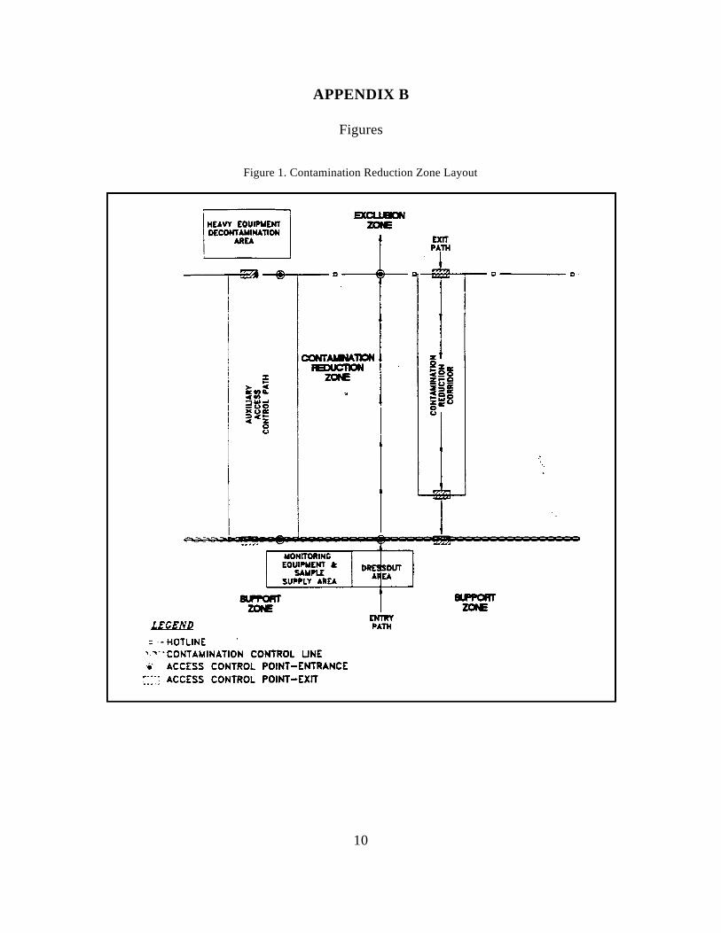
10
APPENDIX B
Figures
Figure 1. Contamination Reduction Zone Layout
HEAVY EQUIPMENT DECONT AIotiNATlON
AREA EXIT PATH
~ ~"l ---....,..-~~~, --(4i1-=~-- 0 -----(ji.r--, c ....
LECEND = .- HOTLINE
SlPfI'ORT' ZONE
MONITORING EQUIPMENT a:
SAWPU SUPPLY AREA
'"'-'CONTAMINATION CONTROL UNE '.- ACCESS CONTROL POINT-ENTRANCE
r---· ACCESS CONTROL POINT-EXIT
DR~50UT AEA
ENTRY PATH
0-----0

11
APPENDIX B (Cont’d.)
Figures
Figure 2. Decontamination Layout
HEAVY EQUIPMENT DECONTAMINATION
AREA SEGREGATED EQUIPMENT DROP
---...,......- c -----.--- c ----;f.~~2=5=::55~'- D ----- C
LECEND - HOTLINE
•• ·CONTAMINATION CONTROL UNE
PLASTIC SHEETING
L. •• ; OVERLAPPING PLASTIC SHEETING
ENTRY PATH
LOW PRESSURE SPRAYER WITH DISTlLl.ED WATER (MAY NOT IE REQUIRED)
ORGANIC SOLVENT SPRAYER (MAY NOT IE REQUIRED)
'- I . CLEAN EQUIPMENT DROP
1
SOP#: 2007DATE: 01/26/95
REV. #: 0.0 GROUNDWATER WELL
SAMPLING
1.0 SCOPE AND APPLICATION
The objective of this standard operating procedure(SOP) is to provide general reference information onsampling of ground water wells. This guideline isprimarily concerned with the collection of watersamples from the saturated zone of the subsurface.Every effort must be made to ensure that the sampleis representative of the particular zone of water beingsampled. These procedures are designed to be used inconjunction with analyses for the most common typesof ground water contaminants (e.g., volatile and semi-volatile organic compounds, pesticides, metals,biological parameters).
These are standard (i.e., typically applicable)operating procedures which may be varied or changedas required, dependent upon site conditions,equipment limitations or limitations imposed by theprocedure. In all instances, the ultimate proceduresemployed should be documented and associated withthe final report.
Mention of trade names or commercial products doesnot constitute U.S. Environmental Protection Agency(EPA) endorsement or recommendation for use.
2.0 METHOD SUMMARY
In order to obtain a representative groundwater samplefor chemical analysis it is important to removestagnant water in the well casing and the waterimmediately adjacent to the well before collection ofthe sample. This may be achieved with one of anumber of instruments. The most common of theseare the bailer, submersible pump, non-contact gasbladder pump, inertia pump and suction pump. At aminimum, three well volumes should be purged, ifpossible. Equipment must be decontaminated prior touse and between wells. Once purging is completedand the correct laboratory-cleaned sample containershave been prepared, sampling may proceed. Samplingmay be conducted with any of the above instruments,
and need not be the same as the device used forpurging. Care should be taken when choosing thesampling device as some will affect the integrity ofthe sample. Sampling should occur in a progressionfrom the least to most contaminated well, if thisinformation is known.
The growing concern over the past several years overlow levels of volatile organic compounds in watersupplies has led to the development of highlysophisticated analytical methods that can providedetection limits at part per trillion levels. While thelaboratory methods are extremely sensitive, wellcontrolled and quality assured, they cannotcompensate for a poorly collected sample. Thecollection of a sample should be as sensitive, highlydeveloped and quality assured as the analyticalprocedures.
3.0 SAMPLE PRESERVATION,CONTAINERS, HANDLING,AND STORAGE
The type of analysis for which a sample is beingcollected determines the type of bottle, preservative,holding time, and filtering requirements. Samplesshould be collected directly from the sampling deviceinto appropriate laboratory cleaned containers. Checkthat a Teflon liner is present in the cap, if required.Attach a sample identification label. Complete a fielddata sheet, a chain of custody form, and record allpertinent data in the site logbook.
Samples shall be appropriately preserved, labelled,logged, and placed in a cooler to be maintained at4EC. Samples must be shipped well before theholding time is up and ideally should be shippedwithin 24 hours of sample collection. It is imperativethat samples be shipped or delivered daily to theanalytical laboratory in order to maximize the timeavailable for the laboratory to perform the analyses.The bottles should be shipped with adequate packingand cooling to ensure that they arrive intact.
2
Sample retrieval systems suitable for the validcollection of volatile organic samples are: positivedisplacement bladder pumps, gear driven submersiblepumps, syringe samplers and bailers (Barcelona, 1984;Nielsen, 1985). Field conditions and other constraintswill limit the choice of appropriate systems. Thefocus of concern must remain to provide a validsample for analysis, one which has been subjected tothe least amount of turbulence possible.
Treatment of the sample with sodium thiosulfatepreservative is required only if there is residualchlorine in the water that could cause free radicalchlorination and change the identity of the originalcontaminants. It should not be used if there is nochlorine in the water.
Holding time for volatiles analysis is seven days. It isimperative that the sample be shipped or delivereddaily to the analytical laboratory. The bottles must beshipped on their sides to aid in maintaining the airtightseal during shipment, with adequate packing andcooling to ensure that they arrive intact.
For collection of volatile organic samples, refer to thework plan to ensure that 40 mL glass sample vialswith Teflon lined septa are ordered and in sufficientnumbers. Check sampling supplies; field kit forchlorine, preservatives, Parafilm, foam sleeves andcoolers. Due to the extreme trace levels at whichvolatile organics are detectable, cross contaminationand introduction of contaminants must be avoided.Trip blanks are incorporated into the shipmentpackage to provide a check against crosscontamination.
4.0 INTERFERENCES ANDPOTENTIAL PROBLEMS
4.1 General
The primary goal in performing ground watersampling is to obtain a representative sample of theground water body. Analysis can be compromised byfield personnel in two primary ways: (1) taking anunrepresentative sample, or (2) by incorrect handlingof the sample. There are numerous ways ofintroducing foreign contaminants into a sample, andthese must be avoided by following strict samplingprocedures and utilizing trained field personnel.
4.2 Purging
In a nonpumping well, there will be little or novertical mixing of the water, and stratification willoccur. The well water in the screened section willmix with the ground water due to normal flowpatterns, but the well water above the screened sectionwill remain isolated, become stagnant, and may lackthe contaminants representative of the ground water.Persons sampling should realize that stagnant watermay contain foreign material inadvertently ordeliberately introduced from the surface, resulting inan unrepresentative sample. To safeguard againstcollecting nonrepresentative stagnant water, thefollowing guidelines and techniques should beadhered to during sampling:
1. As a general rule, all monitor wells should bepumped or bailed prior to sampling. Purgewater should be containerized on site orhandled as specified in the site specificproject plan. Evacuation of a minimum ofone volume of water in the well casing, andpreferably three to five volumes, isrecommended for a representative sample.In a high-yielding ground water formationand where there is no stagnant water in thewell above the screened section, evacuationprior to sample withdrawal is not as critical.However, in all cases where the monitoringdata is to be used for enforcement actions,evacuation is recommended.
2. When purging with a pump (not a bailer), thepump should be set at the screened interval,or if the well is an open-rock well, it shouldbe set at the same depth the sample will becollected. When sampling a screened well,the sample should also be collected from thesame depth the pump was set at.
3. The well should be sampled as soon aspossible after purging.
4. Analytical parameters typically dictatewhether the sample should be collectedthrough the purging device, or through aseparate sampling instrument.
5. For wells that can be pumped or bailed todryness with the equipment being used, thewell should be evacuated and allowed to
3
recover prior to collecting a sample. If the Advantagesrecovery rate is fairly rapid and time allows,evacuation of more than one volume of water C Only practical limitations on size andis preferred. If recovery is slow, sample the materialswell upon recovery after one evacuation.
6. A non-representative sample can also resultfrom excessive pre-pumping of the C Portablemonitoring well. Stratification of theleachate concentration in the ground water C Inexpensive, so it can be dedicated and hungformation may occur, or heavier-than-water in a well, thereby reducing the chances ofcompounds may sink to the lower portions of cross contaminationthe aquifer. Excessive pumping can dilute orincrease the contaminant concentrations from C Minimal outgassing of volatile organicswhat is representative of the sampling point while sample is in bailerof interest.
4.3 Materials
Materials of construction for samplers and evacuationequipment (bladders, pump, bailers, tubing, etc.)should be limited to stainless steel, Teflon , and glassR
in areas where concentrations are expected to be at ornear the detection limit. The tendency of organics toleach into and out of many materials make theselection of materials critical for trace analyses. Theuse of plastics, such as PVC or polyethylene, shouldbe avoided when analyzing for organics. However,PVC may be used for evacuation equipment as it willnot come in contact with the sample, and in highlycontaminated wells, disposable equipment (i.e.,polypropylene bailers) may be appropriate to avoidcross-contamination.
Materials of construction (bladders/ pumps, bailers,tubing, etc.) suitable for collecting and handlingVolatile Organic Samples should be limited tostainless steel, Teflon and glass in areas whichdetection limit range concentrations are expected.The tendency of organics to leach into and out ofmany materials, make the selection of materials Advantagescritical for these trace analyses. The use of plastics,e.g., PVC etc., should be avoided. There are C Portable and can be transported to severalnumerous ways of introducing foreign contaminants wellsinto a sample, and these must be avoided by followingstrict sampling procedures and utlization of trained C Depending upon the size of the pump and thepersonnel. pumping depths, relatively high pumping
4.4 Advantages/Disadvantages ofCertain Equipment
4.4.1 Bailers
C No power source needed
C Readily available
C Removes stagnant water first
C Rapid, simple method for removing smallvolumes of purge water
Disadvantages
C Time-consuming to flush a large well ofstagnant water
C Transfer of sample may cause aeration
C Stoppers at the bottom of the bailer usuallyleak thus the bailer must be brought to thesurface rapidly
C If the bailer is allowed to hit the bottom ofthe well boring, gravel can displace the ballvalve not allowing the bailer to hold water
4.4.2 Submersible Pumps
rates are possible
C Generally very reliable and does not requirepriming

4
Disadvantages C Restricted to areas with water levels within
C Potential for effects on analysis of traceorganics C Vacuum can cause loss of dissolved gasses
C Heavy and cumbersome to deal with,particularly in deeper wells C Pump must be primed and vacuum is often
C Expensive pumping
C Power source needed
C Sediment in water may cause problems withthe pumps
C Impractical in low yielding or shallow wells
4.4.3 Non-Contact Gas Bladder Pumps
Advantages Disadvantages
C Maintains integrity of sample C Restricted to areas with water levels within
C Easy to use
C Can sample from discrete locations within these manual pumpsthe monitor well
Disadvantages
C Difficulty in cleaning, though dedicated diameter wellstubing and bladder may be used
C Only useful to about 100 feet
C Supply of gas for operation, gas bottlesand/or compressors are often difficult toobtain and are cumbersome
C Relatively low pumping rates
C Requires air compressor or pressurized gassource and control box
4.4.4 Suction Pumps
Advantages
C Portable, inexpensive, and readily available
Disadvantages
20 to 25 feet of the ground surface
and volatile organics
difficult to maintain during initial stages of
4.4.5 Inertia Pumps
Advantages
C Portable, inexpensive, and readily available
C Offers a rapid method for purging relativelyshallow wells
70 feet of the ground surface
C May be time consuming to purge wells with
C Labor intensive
C WaTerra pumps are only effective in 2-inch
5.0 EQUIPMENT APPARATUS
5.1 Equipment Checklist
5.1.1 General
C Water level indicator - electric sounder- steel tape- transducer- reflection sounder- airline
C Depth sounderC Appropriate keys for well cap locksC Steel brushC HNU or OVA (whichever is most
appropriate)C LogbookC CalculatorC Field data sheets and samples labels

5
C Chain of custody records and seals - wire strippersC Sample containers - electrical tapeC Engineer's rule - heat shrinkC Sharp knife (locking blade) - hose connectorsC Tool box (to include at least: screwdrivers, - Teflon tape
pliers, hacksaw, hammer, flashlight, C Winch, pulley or hoistadjustable wrench) C Gasoline for generator/gas can
C Leather work gloves C Flow meter with gate valveC Appropriate Health & Safety gear C 1" nipples and various plumbing (i.e., pipeC 5-gallon pail connectors)C Plastic sheeting C Control box (if necessary)C Shipping containersC Packing materialsC Bolt cuttersC Ziploc plastic bags C Containers for evacuation liquidsC Decontamination solutions C Tap waterC Non phosphate soapC Several brushesC Pails or tubsC Aluminum foilC Garden sprayer C Preservatives C Distilled or deionized waterC Fire extinguisher (if using a generator for
your power source)
5.1.2 Bailers
C Clean, decontaminated bailers of appropriatesize and construction material
C Nylon line, enough to dedicate to each wellC Teflon coated bailer wireC Sharp knifeC Aluminum foil (to wrap clean bailers)C Five gallon bucket
5.1.3 Submersible Pump
C Pump(s)C Generator (110, 120, or 240 volt) or 12 volt
battery if inaccessible to field vehicle - ampmeter is useful
C 1" black PVC coil tubing - enough todedicate to each well
C Hose clampsC Safety cable C Tool box supplement
- pipe wrenches
5.1.4 Non-Gas Contact Bladder Pump
C Non-gas contact bladder pumpC Compressor or nitrogen gas tankC Batteries and chargerC Teflon tubing - enough to dedicate to each
wellC Swagelock fittingC Toolbox supplements - same as submersible
pumpC Control box (if necessary)
5.1.5 Suction Pump
C PumpC 1" black PVC coil tubing - enough to
dedicate to each wellC Gasoline - if requiredC ToolboxC Plumbing fittingsC Flow meter with gate valve
5.1.6 Inertia Pump
C Pump assembly (WaTerra pump, pistonpump)
C Five gallon bucket
6.0 REAGENTS
Reagents may be utilized for preservation of samplesand for decontamination of sampling equipment. Thepreservatives required are specified by the analysis tobe performed. Decontamination solutions arespecified in ERT SOP #2006, Sampling EquipmentDecontamination.

6
7.0 PROCEDURE
7.1 Preparation
1. Determine the extent of the sampling effort,the sampling methods to be employed, andthe types and amounts of equipment andsupplies needed (i.e, diameter and depth ofwells to be sampled).
2. Obtain necessary sampling and monitoringequipment, appropriate to type ofcontaminant being investigated. Forcollection of volatile organic samples, referto the work plan to ensure that 40 mL glasssample vials with Teflon lined septa areordered and in sufficient numbers. Checksampling supplies; field kit for chlorine,preservatives, Parafilm, foam sleeves andcoolers. Due to extreme trace levels atwhich volatile organics are detectable, crosscontamination and introduction ofcontaminants must be avoided. Trip blanksare incorporated into the shipment package toprovide a check against cross contamination.
3. Decontaminate or preclean equipment, andensure that it is in working order.
4. Prepare scheduling and coordinate with staff,clients, and regulatory agency, if appropriate.
5. Perform a general site survey prior to siteentry in accordance with the site specificHealth and Safety Plan.
6. Identify and mark all sampling locations.
7.2 Field Preparation
1. Start at the least contaminated well, ifknown.
2. Lay plastic sheeting around the well tominimize likelihood of contamination ofequipment from soil adjacent to the well.
3. Remove locking well cap, note location, timeof day, and date in field notebook orappropriate log form.
4. Remove well casing cap.
5. Screen headspace of well with an appropriatemonitoring instrument to determine thepresence of volatile organic compounds andrecord in site logbook.
6. Lower water level measuring device orequivalent (i.e., permanently installedtransducers or airline) into well until watersurface is encountered.
7. Measure distance from water surface toreference measuring point on well casing orprotective barrier post and record in sitelogbook. Alternatively, if no reference point,note that water level measurement is fromtop of steel casing, top of PVC riser pipe,from ground surface, or some other positionon the well head.
If floating organics are of concern, this canbe determined by measuring the water levelwith an oil/water interface probe whichmeasures floating organics.
8. Measure total depth of well (at least twice toconfirm measurement) and record in sitelogbook or on field data sheet.
9. Calculate the volume of water in the well andthe volume to be purged using thecalculations in Section 8.0.
10. Select the appropriate purging and samplingequipment.
11. If residual chlorine is suspected, use theHach Field Test Kit for chlorine to determineif there is residual chlorine in the water to besampled. If there is, treat the sample vialwith a crystal of sodium thiosulfate prior tosample collection.
7.3 Purging
The amount of flushing a well receives prior to samplecollection depends on the intent of the monitoringprogram as well as the hydrogeologic conditions.Programs where overall quality determination of waterresources are involved may require long pumpingperiods to obtain a sample that is representative of alarge volume of that aquifer. The pumped volume canbe determined prior to sampling so that the sample is
7
a collected after a known volume of the water is foreign materials.evacuated from the aquifer, or the well can be pumpeduntil the stabilization of parameters such as 3. Attach the line to the bailer and slowly lowertemperature, electrical conductance, pH, or turbidity until the bailer is completely submerged,has occurred. being careful not to drop the bailer to the
However, monitoring for defining a contaminant loss of volatile organic contaminants.plume requires a representative sample of a smallvolume of the aquifer. These circumstances require 4. Pull bailer out ensuring that the line eitherthat the well be pumped enough to remove the falls onto a clean area of plastic sheeting orstagnant water but not enough to induce flow from never touches the ground.other areas. Generally, three well volumes areconsidered effective, or calculations can be made to 5. Empty the bailer into a pail until full todetermine, on the basis of the aquifer parameters and determine the number of bails necessary towell dimensions, the appropriate volume to remove achieve the required purge volume.prior to sampling.
During purging, water level measurements may be and dispose of purge waters as specified intaken regularly at 15-30 second intervals. This data the site specific sampling plan.may be used to compute aquifer transmissivity andother hydraulic characteristics. The following wellevacuation devices are most commonly used. Otherevacuation devices are available, but have beenomitted in this discussion due to their limited use.
7.3.1 Bailers
Bailers are the simplest purging device used and have can be disassembled easily to allow surfaces contactedmany advantages. They generally consist of a rigid by contaminants to be cleaned, field decontaminationlength of tube, usually with a ball check-valve at the may be difficult and require solvents that can affectbottom. A line is used to lower the bailer into the sample analysis. The use of submersible pumps inwell and retrieve a volume of water. The three most multiple well-sampling programs, therefore, should becommon types of bailer are PVC, Teflon, and stainless carefully considered against other samplingsteel. mechanisms (bailers, bladder pumps). In most cases,
This manual method of purging is best suited to a submersible pump, however, submersible pumpsshallow or narrow diameter wells. For deep, larger may be the only practical sampling device fordiameter wells which require evacuation of large extremely deep wells (greater than 300 feet of water).volumes of water, other mechanical devices may be Under those conditions, dedicated pump systemsmore appropriate. should be installed to eliminate the potential for cross-
7.3.1.1 Operation
Equipment needed will include a cleandecontaminated bailer, Teflon or nylon line, a sharpknife, and plastic sheeting.
1. Determine the volume of water to be purgedas described in 8.0, calculations.
2. Lay plastic sheeting around the well toprevent contamination of the bailer line with
water, causing turbulence and the possible
6. Thereafter, pour the water into a container
7.3.2 Submersible Pumps
The use of submersible pumps for sample collectionis permissible provided they are constructed ofsuitably noncontaminating materials. The chiefdrawback, however, is the difficulty avoiding cross-contamination between wells. Although some units
a sample can be collected by bailer after purging with
contamination of well samples.
Submersible pumps generally use one of two types ofpower supplies, either electric or compressed gas orair. Electric powered pumps can run off a 12 volt DCrechargeable battery, or a 110 or 220 volt AC powersupply. Those units powered by compressed airnormally use a small electric or gas-powered aircompressor. They may also utilize compressed gas(i.e., nitrogen) from bottles. Different size pumps areavailable for different depth or diameter monitoringwells.
8
7.3.2.1 Operation
1. Determine the volume of water to be purgedas described in 8.0 Calculations.
2. Lay plastic sheeting around the well toprevent contamination of pumps, hoses orlines with foreign materials.
3. Assemble pump, hoses and safety cable, and They include: centrifugal, peristaltic and diaphragm.lower the pump into the well. Make sure the Diaphragm pumps can be used for well evacuation atpump is deep enough so all the water is not a fast pumping rate and sampling at a low pumpingevacuated. (Running the pump without water rate. The peristaltic pump is a low volume pump thatmay cause damage.) uses rollers to squeeze the flexible tubing thereby
4. Attach flow meter to the outlet hose to well to prevent cross contamination. Peristalticmeasure the volume of water purged. pumps, however, require a power source.
5. Use a ground fault circuit interrupter (GFCI)or ground the generator to avoid possibleelectric shock.
6. Attach power supply, and purge the welluntil the specified volume of water has beenevacuated (or until field parameters, such astemperature, pH, conductivity, etc, havestabilized). Do not allow the pump to rundry. If the pumping rate exceeds the wellrecharge rate, lower the pump further into thewell, and continue pumping.
7. Collect and dispose of purge waters asspecified in the site specific sampling plan.
7.3.3 Non-Contact Gas Bladder Pumps
For this procedure, an all stainless-steel and TeflonMiddleburg-squeeze bladder pump (e.g., IEA,TIMCO, Well Wizard, Geoguard, and others) is usedto provide the least amount of material interference tothe sample (Barcelona, 1985). Water comes intocontact with the inside of the bladder (Teflon) and thesample tubing, also Teflon, that may be dedicated toeach well. Some wells may have permanentlyinstalled bladder pumps, (i.e., Well Wizard,Geoguard), that will be used to sample for allparameters.
7.3.3.1 Operation
1. Assemble Teflon tubing, pump and chargedcontrol box.
2. Procedure for purging with a bladder pump is
the same as for a submersible pump (Section7.3.2.1).
3. Be sure to adjust flow rate to prevent violentjolting of the hose as sample is drawn in.
7.3.4 Suction Pumps
There are many different types of suction pumps.
creating suction. This tubing can be dedicated to a
7.3.4.1 Operation
1. Assembly of the pump, tubing, and powersource if necessary.
2. Procedure for purging with a suction pump isexactly the same as for a submersible pump(Section 7.3.2.1).
7.3.5 Inertia Pumps
Inertia pumps such as the WaTerra pump and pistonpump, are manually operated. They are mostappropriate to use when wells are too deep to bail byhand, or too shallow or narrow (or inaccessible) towarrant an automatic (submersible, etc.) pump. Thesepumps are made of plastic and may be eitherdecontaminated or discarded.
7.3.5.1 Operation
1. Determine the volume of water to be purgedas described in 8.0, Calculations.
2. Lay plastic sheeting around the well toprevent contamination of pumps or hoseswith foreign materials.
3. Assemble pump and lower to the appropriatedepth in the well.
4. Begin pumping manually, discharging waterinto a 5 gallon bucket (or other graduatedvessel). Purge until specified volume ofwater has been evacuated (or until fieldparameters such as temperature, pH,
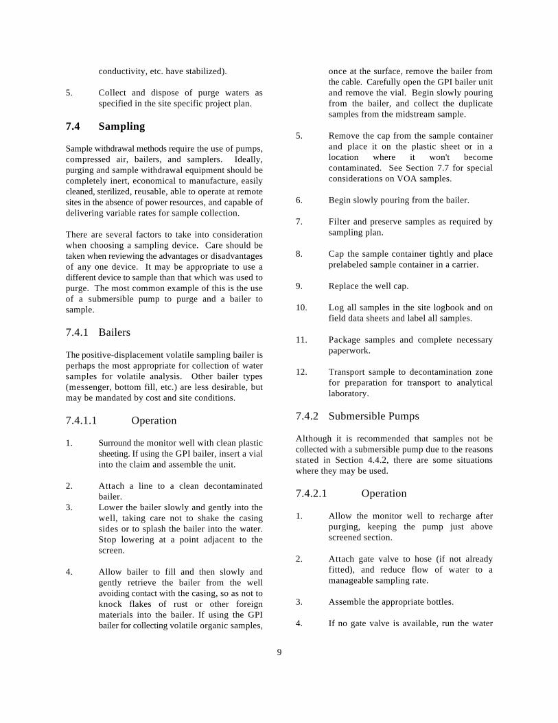
9
conductivity, etc. have stabilized). once at the surface, remove the bailer from
5. Collect and dispose of purge waters as and remove the vial. Begin slowly pouringspecified in the site specific project plan. from the bailer, and collect the duplicate
7.4 Sampling
Sample withdrawal methods require the use of pumps,compressed air, bailers, and samplers. Ideally,purging and sample withdrawal equipment should becompletely inert, economical to manufacture, easilycleaned, sterilized, reusable, able to operate at remotesites in the absence of power resources, and capable ofdelivering variable rates for sample collection.
There are several factors to take into considerationwhen choosing a sampling device. Care should betaken when reviewing the advantages or disadvantagesof any one device. It may be appropriate to use adifferent device to sample than that which was used topurge. The most common example of this is the useof a submersible pump to purge and a bailer tosample.
7.4.1 Bailers
The positive-displacement volatile sampling bailer isperhaps the most appropriate for collection of watersamples for volatile analysis. Other bailer types(messenger, bottom fill, etc.) are less desirable, butmay be mandated by cost and site conditions.
7.4.1.1 Operation
1. Surround the monitor well with clean plasticsheeting. If using the GPI bailer, insert a vialinto the claim and assemble the unit.
2. Attach a line to a clean decontaminatedbailer.
3. Lower the bailer slowly and gently into thewell, taking care not to shake the casingsides or to splash the bailer into the water.Stop lowering at a point adjacent to thescreen.
4. Allow bailer to fill and then slowly andgently retrieve the bailer from the wellavoiding contact with the casing, so as not toknock flakes of rust or other foreignmaterials into the bailer. If using the GPIbailer for collecting volatile organic samples,
the cable. Carefully open the GPI bailer unit
samples from the midstream sample.
5. Remove the cap from the sample containerand place it on the plastic sheet or in alocation where it won't becomecontaminated. See Section 7.7 for specialconsiderations on VOA samples.
6. Begin slowly pouring from the bailer.
7. Filter and preserve samples as required bysampling plan.
8. Cap the sample container tightly and placeprelabeled sample container in a carrier.
9. Replace the well cap.
10. Log all samples in the site logbook and onfield data sheets and label all samples.
11. Package samples and complete necessarypaperwork.
12. Transport sample to decontamination zonefor preparation for transport to analyticallaboratory.
7.4.2 Submersible Pumps
Although it is recommended that samples not becollected with a submersible pump due to the reasonsstated in Section 4.4.2, there are some situationswhere they may be used.
7.4.2.1 Operation
1. Allow the monitor well to recharge afterpurging, keeping the pump just abovescreened section.
2. Attach gate valve to hose (if not alreadyfitted), and reduce flow of water to amanageable sampling rate.
3. Assemble the appropriate bottles.
4. If no gate valve is available, run the water
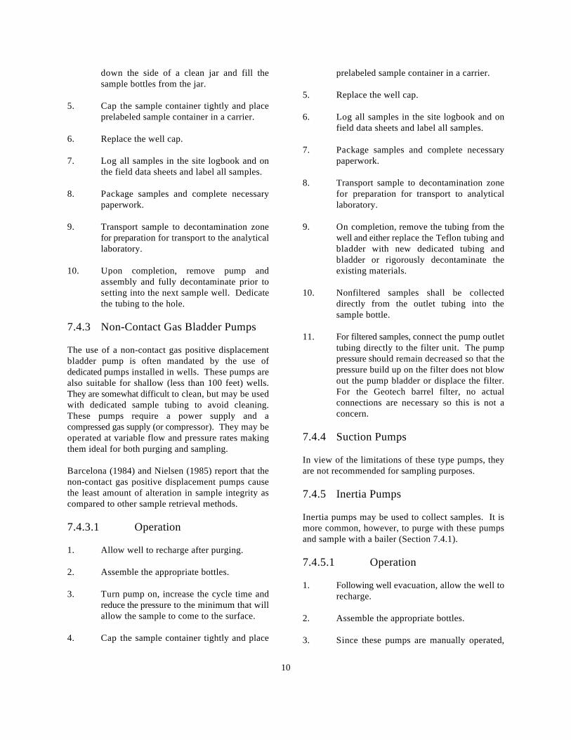
10
down the side of a clean jar and fill the prelabeled sample container in a carrier.sample bottles from the jar.
5. Cap the sample container tightly and placeprelabeled sample container in a carrier. 6. Log all samples in the site logbook and on
6. Replace the well cap.
7. Log all samples in the site logbook and on paperwork.the field data sheets and label all samples.
8. Package samples and complete necessary for preparation for transport to analyticalpaperwork. laboratory.
9. Transport sample to decontamination zone 9. On completion, remove the tubing from thefor preparation for transport to the analytical well and either replace the Teflon tubing andlaboratory. bladder with new dedicated tubing and
10. Upon completion, remove pump and existing materials.assembly and fully decontaminate prior tosetting into the next sample well. Dedicate 10. Nonfiltered samples shall be collectedthe tubing to the hole. directly from the outlet tubing into the
7.4.3 Non-Contact Gas Bladder Pumps
The use of a non-contact gas positive displacementbladder pump is often mandated by the use ofdedicated pumps installed in wells. These pumps arealso suitable for shallow (less than 100 feet) wells.They are somewhat difficult to clean, but may be usedwith dedicated sample tubing to avoid cleaning.These pumps require a power supply and acompressed gas supply (or compressor). They may beoperated at variable flow and pressure rates makingthem ideal for both purging and sampling.
Barcelona (1984) and Nielsen (1985) report that the are not recommended for sampling purposes.non-contact gas positive displacement pumps causethe least amount of alteration in sample integrity ascompared to other sample retrieval methods.
7.4.3.1 Operation
1. Allow well to recharge after purging.
2. Assemble the appropriate bottles.
3. Turn pump on, increase the cycle time andreduce the pressure to the minimum that willallow the sample to come to the surface.
4. Cap the sample container tightly and place
5. Replace the well cap.
field data sheets and label all samples.
7. Package samples and complete necessary
8. Transport sample to decontamination zone
bladder or rigorously decontaminate the
sample bottle.
11. For filtered samples, connect the pump outlettubing directly to the filter unit. The pumppressure should remain decreased so that thepressure build up on the filter does not blowout the pump bladder or displace the filter.For the Geotech barrel filter, no actualconnections are necessary so this is not aconcern.
7.4.4 Suction Pumps
In view of the limitations of these type pumps, they
7.4.5 Inertia Pumps
Inertia pumps may be used to collect samples. It ismore common, however, to purge with these pumpsand sample with a bailer (Section 7.4.1).
7.4.5.1 Operation
1. Following well evacuation, allow the well torecharge.
2. Assemble the appropriate bottles.
3. Since these pumps are manually operated,
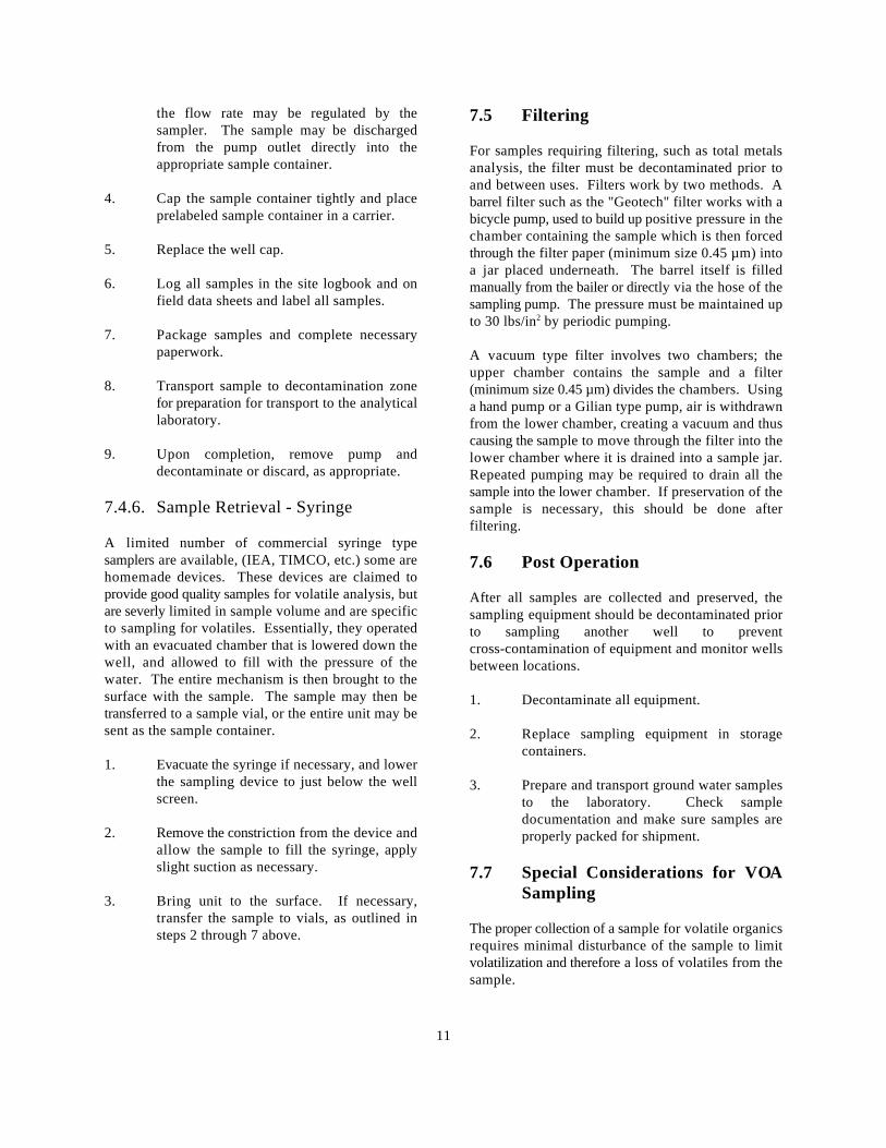
11
the flow rate may be regulated by thesampler. The sample may be dischargedfrom the pump outlet directly into theappropriate sample container.
4. Cap the sample container tightly and placeprelabeled sample container in a carrier.
5. Replace the well cap.
6. Log all samples in the site logbook and onfield data sheets and label all samples.
7. Package samples and complete necessarypaperwork.
8. Transport sample to decontamination zonefor preparation for transport to the analyticallaboratory.
9. Upon completion, remove pump anddecontaminate or discard, as appropriate.
7.4.6. Sample Retrieval - Syringe
A limited number of commercial syringe typesamplers are available, (IEA, TIMCO, etc.) some arehomemade devices. These devices are claimed toprovide good quality samples for volatile analysis, butare severly limited in sample volume and are specificto sampling for volatiles. Essentially, they operatedwith an evacuated chamber that is lowered down thewell, and allowed to fill with the pressure of thewater. The entire mechanism is then brought to thesurface with the sample. The sample may then betransferred to a sample vial, or the entire unit may besent as the sample container.
1. Evacuate the syringe if necessary, and lowerthe sampling device to just below the wellscreen.
2. Remove the constriction from the device andallow the sample to fill the syringe, applyslight suction as necessary.
3. Bring unit to the surface. If necessary,transfer the sample to vials, as outlined insteps 2 through 7 above.
7.5 Filtering
For samples requiring filtering, such as total metalsanalysis, the filter must be decontaminated prior toand between uses. Filters work by two methods. Abarrel filter such as the "Geotech" filter works with abicycle pump, used to build up positive pressure in thechamber containing the sample which is then forcedthrough the filter paper (minimum size 0.45 µm) intoa jar placed underneath. The barrel itself is filledmanually from the bailer or directly via the hose of thesampling pump. The pressure must be maintained upto 30 lbs/in by periodic pumping.2
A vacuum type filter involves two chambers; theupper chamber contains the sample and a filter(minimum size 0.45 µm) divides the chambers. Usinga hand pump or a Gilian type pump, air is withdrawnfrom the lower chamber, creating a vacuum and thuscausing the sample to move through the filter into thelower chamber where it is drained into a sample jar.Repeated pumping may be required to drain all thesample into the lower chamber. If preservation of thesample is necessary, this should be done afterfiltering.
7.6 Post Operation
After all samples are collected and preserved, thesampling equipment should be decontaminated priorto sampling another well to preventcross-contamination of equipment and monitor wellsbetween locations.
1. Decontaminate all equipment.
2. Replace sampling equipment in storagecontainers.
3. Prepare and transport ground water samplesto the laboratory. Check sampledocumentation and make sure samples areproperly packed for shipment.
7.7 Special Considerations for VOASampling
The proper collection of a sample for volatile organicsrequires minimal disturbance of the sample to limitvolatilization and therefore a loss of volatiles from thesample.
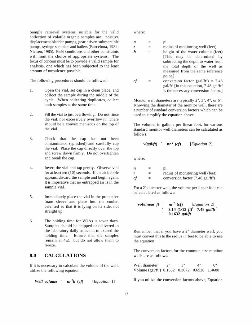
Well volume '' nr 2h (cf) [Equation 1]
v(gal/ft) '' nr 2 (cf) [Equation 2]
vol/linear ft '' nr 2 (cf) [Equation 2]' 3.14 (1/12 ft)2 7.48 gal/ft 3
' 0.1632 gal/ft
12
Sample retrieval systems suitable for the valid where:collection of volatile organic samples are: positivedisplacement bladder pumps, gear driven submersiblepumps, syringe samplers and bailers (Barcelona, 1984;Nielsen, 1985). Field conditions and other constraintswill limit the choice of appropriate systems. Thefocus of concern must be to provide a valid sample foranalysis, one which has been subjected to the leastamount of turbulence possible.
The following procedures should be followed:
1. Open the vial, set cap in a clean place, andcollect the sample during the middle of thecycle. When collecting duplicates, collectboth samples at the same time.
2. Fill the vial to just overflowing. Do not rinsethe vial, nor excessively overflow it. Thereshould be a convex meniscus on the top ofthe vial.
3. Check that the cap has not beencontaminated (splashed) and carefully capthe vial. Place the cap directly over the topand screw down firmly. Do not overtightenand break the cap.
4. Invert the vial and tap gently. Observe vialfor at least ten (10) seconds. If an air bubbleappears, discard the sample and begin again.It is imperative that no entrapped air is in thesample vial.
5. Immediately place the vial in the protectivefoam sleeve and place into the cooler,oriented so that it is lying on its side, notstraight up.
6. The holding time for VOAs is seven days.Samples should be shipped or delivered tothe laboratory daily so as not to exceed theholding time. Ensure that the samplesremain at 4EC, but do not allow them tofreeze.
8.0 CALCULATIONS
If it is necessary to calculate the volume of the well,utilize the following equation:
n = pir = radius of monitoring well (feet)h = height of the water column (feet)
[This may be determined bysubtracting the depth to water fromthe total depth of the well asmeasured from the same referencepoint.]
cf = conversion factor (gal/ft ) = 7.483
gal/ft [In this equation, 7.48 gal/ft3 3
is the necessary conversion factor.]
Monitor well diameters are typically 2", 3", 4", or 6".Knowing the diameter of the monitor well, there area number of standard conversion factors which can beused to simplify the equation above.
The volume, in gallons per linear foot, for variousstandard monitor well diameters can be calculated asfollows:
where:
n = pir = radius of monitoring well (feet)cf = conversion factor (7.48 gal/ft )3
For a 2" diameter well, the volume per linear foot canbe calculated as follows:
Remember that if you have a 2" diameter well, youmust convert this to the radius in feet to be able to usethe equation.
The conversion factors for the common size monitorwells are as follows:
Well diameter 2" 3" 4" 6"Volume (gal/ft.) 0.1632 0.3672 0.6528 1.4688
If you utilize the conversion factors above, Equation
Well volume '' (h)(cf) [Equation 3]
13
1 should be modified as follows: must be implemented prior to sampling the first well.
where: such as minimizing contact with potentialcontaminants in both the vapor phase and liquid
h = height of water column (feet)cf = the conversion factor calculated
from Equation 2
The well volume is typically tripled to determine thevolume to be purged.
9.0 QUALITY ASSURANCE/QUALITY CONTROL
There are no specific quality assurance (QA) activitieswhich apply to the implementation of theseprocedures. However, the following general QAprocedures apply:
1. All data must be documented on field datasheets or within site logbooks.
2. All instrumentation must be operated inaccordance with operating instructions assupplied by the manufacturer, unlessotherwise specified in the work plan.Equipment checkout and calibrationactivities must occur prior tosampling/operation and they must bedocumented.
3. The collection of rinsate blanks isrecommended to evaluate potential for crosscontamination from the purging and/orsampling equipment.
4. Trip blanks are required if analyticalparameters include VOAs.
10.0 DATA VALIDATION
This section is not applicable to this SOP.
11.0 HEALTH AND SAFETY
When working with potentially hazardous materials,follow U.S. EPA, OSHA or REAC health and safetyguidelines. More specifically, depending upon the sitespecific contaminants, various protective programs
The site health and safety plan should be reviewedwith specific emphasis placed on the protectionprogram planned for the well sampling tasks.Standard safe operating practices should be followed
matrix through the use of respirators and disposableclothing.
When working around volatile organic contaminants:
1. Avoid breathing constituents venting fromthe well.
2. Pre-survey the well head-space with anFID/PID prior to sampling.
3. If monitoring results indicate organicconstituents, sampling activities may beconducted in Level C protection. At aminimum, skin protection will be afforded bydisposable protective clothing.
Physical hazards associated with well sampling:
1. Lifting injuries associated with pump andbailers retrieval; moving equipment.
2. Use of pocket knives for cutting dischargehose.
3. Heat/cold stress as a result of exposure toextreme temperatures and protectiveclothing.
4. Slip, trip, fall conditions as a result of pumpdischarge.
5. Restricted mobility due to the wearing ofprotective clothing.
6. Electrical shock associated with use ofsubmersible pumps is possible. Use a GFCIor a copper grounding stake to avoid thisproblem.
12.0 REFERENCES
Barcelona, M.J., Helfrich, J.A., Garske, E.E., and J.P.Gibb, Spring 1984. "A Laboratory Evaluation ofGroundwater Sampling Mechanisms," Groundwater
14
Monitoring Review, 1984 pp. 32-41. Development. 1980, Ada, OK.
Barcelona, M.J., Helfrich, J.A., and Garske, E.E., Sisk, S.W. NEIC Manual for Ground/Surface"Sampling Tubing Effects on Groundwater Samples", Investigations at Hazardous Waste Sites,Analy. Chem., Vol. 57, 1985 pp. 460-463. EPA-330/9-81-002, 1981.
Driscoll, F.G., Groundwater and Wells (2nd ed.) U.S. Department of the Interior, National HandbookJohnson Division, UOP Inc., St. Paul, Minnesota, of Recommended Methods for Water-Data1986, 1089 pp. Acquisition, Reston, Virginia.
Gibb, J.P., R.M. Schuller, and R.A. Griffin,. U.S. Environmental Protection Agency, 1977.Monitoring Well Sampling and Preservation Procedures Manual for Groundwater Monitoring atTechniques, EPA-600/9-80-010, 1980. March, 1980. Solid Waste Disposal Facilities. EPA-530/SW-611.
Instrument Specialties Company, (January).Instruction Manual, Model 2100 Wastewater Sampler, U.S. Code of Federal Regulations, 49 CFR Parts 100Lincoln, Nebraska, 1980. to 177, Transportation revised November 1, 1985.
Keely, J.F. and Kwasi Boateng, Monitoring Well U.S. Environmental Protection Agency, 1982.Installation, Purging and Sampling Techniques - Part Handbook for Chemical and Sample Preservation ofI: Conceptualizations, Groundwater V25, No. 3, 1987 Water and Wastewater, EPA-600/4-82-029,pp. 300-313. Washington, D.C.
Keith, Lawrence H., Principles of Environmental U.S. Environmental Protection Agency, 1983.Sampling, American Chemical Society, 1988. Methods for Chemical Analysis of Water and Waste,
Korte, Nic, and Dennis Ealey,. Procedures for FieldChemical Analyses of Water Samples, U.S. U.S. Environmental Protection Agency, 1984. TestDepartment of Energy, GJ/TMC-07, Technical Methods for Evaluation of Solid Waste,Measurements Center, Grand Junction Project Office, EPA-SW-846, Second Edition, Washington, D.C.1983.
Korte, Nic, and Peter Kearl,. Procedures for the Manual of Groundwater Quality Sampling Procedures,Collection and Preservation of Groundwater and EPA-600/2-81-160, Washington, D.C.Surface Water Samples and for the Installation ofMonitoring Wells: Second Edition, U.S. Department U.S. Environmental Protection Agency, 1985.of Energy, GJ/TMC-08, Technical Measurements Practical Guide for Groundwater Sampling,Center, Grand Junction Projects Office, 1985. EPA-600/2-85/104, September, 1985.
National Council of the Paper Industry for Air and U.S. Environmental Protection Agency, 1986. RCRAStream Improvement, Inc.,. A Guide to Groundwater Groundwater Monitoring Technical EnforcementSampling, Technical Bulletin No. 362, Madison, New Guidance Document, OSWER-9950-1, September,York. January, 1982. 1986.
Nielsen, David M. and Yeates, Gillian L., Spring. "A Weston, 1987. Standard Operations Procedures forComparison of Sampling Mechanisms Available for Monitor Well Installation. MOUND IGMP/RIP.Small-Diameter Groundwater Monitoring Wells,"Groundwater Monitoring Review, 1985 pp. 83-99. U.S. Environmental Protection Agency, 1982.
Scalf, et al. (M.J. Scalf, McNabb, W. Dunlap, R. Water and Wastewater, EPA-600/4-82-029,Crosby, and J. Fryberger),. Manual for Groundwater Washington, D.C.Sampling Procedures. R.S. Kerr EnvironmentalResearch Laboratory, Office of Research and --- 1981. Manual of Groundwater Quality
August, 1977.
EPA-600/4-79-020, Washington, D.C.
U.S. Environmental Protection Agency, 1981.
Handbook for Sampling and Sample Preservation of
15
Sampling Procedures, EPA-600/2-81-160, WESTON, 1987. Standard Operating Procedures forWashington, D.C. Monitor Well Installation. MOUND IGMP/RIP
--- 1985. Practice Guide for Groundwater Barcelona, M.J. Helfrich, J.A., and Garske, E.E.,Sampling, EPA-600/2/85-104, September "Sampling Tubing Effects on Groundwater Samples".1985. 1985, Analy. Chem., Vol. 57, pp. 460-463.
Nielsen, David M. and Yeates, Gillian L., Spring1985. "A Comparison of Sampling MechanismsAvailable for Small-Diameter GroundwaterMonitoring Wells," Groundwater Monitoring Review,pp. 83-99.
U. S. EPA ENVIRONMENTAL RESPONSE TEAM
STANDARD OPERATING PROCEDURESSOP: 2012
PAGE: 1 of 13REV: 0.0
DATE: 02/18/00SOIL SAMPLING
CONTENTS
1.0 SCOPE AND APPLICATION
2.0 METHOD SUMMARY
3.0 SAMPLE PRESERVATION, CONTAINERS, HANDLING, AND STORAGE
4.0 POTENTIAL PROBLEMS
5.0 EQUIPMENT
6.0 REAGENTS
7.0 PROCEDURES
7.1 Preparation7.2 Sample Collection
7.2.1 Surface Soil Samples7.2.2 Sampling at Depth with Augers and Thin Wall Tube Samplers7.2.3 Sampling at Depth with a Trier7.2.4 Sampling at Depth with a Split Spoon (Barrel) Sampler7.2.5 Test Pit/Trench Excavation
8.0 CALCULATIONS
9.0 QUALITY ASSURANCE/QUALITY CONTROL
10.0 DATA VALIDATION
11.0 HEALTH AND SAFETY
12.0 REFERENCES
13.0 APPENDIX Figures
SUPERCEDES: SOP #2012; Revision 0.0; 11/16/94; U.S. EPA Contract 68-C4-0022.
U. S. EPA ENVIRONMENTAL RESPONSE TEAM
STANDARD OPERATING PROCEDURESSOP: 2012
PAGE: 2 of 13REV: 0.0
DATE: 02/18/00SOIL SAMPLING
1.0 SCOPE AND APPLICATION
The purpose of this standard operating procedure (SOP) is to describe the procedures for the collection ofrepresentative soil samples. Sampling depths are assumed to be those that can be reached without the useof a drill rig, direct-push, or other mechanized equipment (except for a back-hoe). Analysis of soil samplesmay determine whether concentrations of specific pollutants exceed established action levels, or if theconcentrations of pollutants present a risk to public health, welfare, or the environment.
These are standard (i.e., typically applicable) operating procedures which may be varied or changed asrequired, dependent upon site conditions, equipment limitations or limitations imposed by the procedure.In all instances, the actual procedures used should be documented and described in an appropriate sitereport.
Mention of trade names or commercial products does not constitute U.S. Environmental Protection Agency(EPA) endorsement or recommendation for use.
2.0 METHOD SUMMARY
Soil samples may be collected using a variety of methods and equipment depending on the depth of thedesired sample, the type of sample required (disturbed vs. undisturbed), and the soil type. Near-surfacesoils may be easily sampled using a spade, trowel, and scoop. Sampling at greater depths may beperformed using a hand auger, continuous flight auger, a trier, a split-spoon, or, if required, a backhoe.
3.0 SAMPLE PRESERVATION, CONTAINERS, HANDLING, AND STORAGE
Chemical preservation of solids is not generally recommended. Samples should, however, be cooled andprotected from sunlight to minimize any potential reaction. The amount of sample to be collected andproper sample container type are discussed in ERT/REAC SOP #2003 Rev. 0.0 08/11/94, Sample Storage,Preservation and Handling.
4.0 INTERFERENCES AND POTENTIAL PROBLEMS
There are two primary potential problems associated with soil sampling - cross contamination of samplesand improper sample collection. Cross contamination problems can be eliminated or minimized throughthe use of dedicated sampling equipment. If this is not possible or practical, then decontamination ofsampling equipment is necessary. Improper sample collection can involve using contaminated equipment,disturbance of the matrix resulting in compaction of the sample, or inadequate homogenization of thesamples where required, resulting in variable, non-representative results.
5.0 EQUIPMENT

U. S. EPA ENVIRONMENTAL RESPONSE TEAM
STANDARD OPERATING PROCEDURESSOP: 2012
PAGE: 3 of 13REV: 0.0
DATE: 02/18/00SOIL SAMPLING
Soil sampling equipment includes the following:
C Maps/plot planC Safety equipment, as specified in the site-specific Health and Safety PlanC Survey equipment or global positioning system (GPS) to locate sampling pointsC Tape measureC Survey stakes or flagsC Camera and filmC Stainless steel, plastic, or other appropriate homogenization bucket, bowl or panC Appropriate size sample containersC Ziplock plastic bagsC LogbookC LabelsC Chain of Custody records and custody sealsC Field data sheets and sample labelsC Cooler(s)C IceC VermiculiteC Decontamination supplies/equipmentC Canvas or plastic sheetC Spade or shovelC SpatulaC ScoopC Plastic or stainless steel spoonsC Trowel(s)C Continuous flight (screw) augerC Bucket augerC Post hole augerC Extension rodsC T-handleC Sampling trierC Thin wall tube samplerC Split spoonsC Vehimeyer soil sampler outfit
- Tubes- Points- Drive head- Drop hammer- Puller jack and grip
C Backhoe
6.0 REAGENTS

U. S. EPA ENVIRONMENTAL RESPONSE TEAM
STANDARD OPERATING PROCEDURESSOP: 2012
PAGE: 4 of 13REV: 0.0
DATE: 02/18/00SOIL SAMPLING
Reagents are not used for the preservation of soil samples. Decontamination solutions are specified inERT/REAC SOP #2006 Rev. 0.0 08/11/94, Sampling Equipment Decontamination, and the site specificwork plan.
7.0 PROCEDURES
7.1 Preparation
1. Determine the extent of the sampling effort, the sampling methods to be employed, and thetypes and amounts of equipment and supplies required.
2. Obtain necessary sampling and monitoring equipment.
3. Decontaminate or pre-clean equipment, and ensure that it is in working order.
4. Prepare schedules and coordinate with staff, client, and regulatory agencies, if appropriate.
5. Perform a general site survey prior to site entry in accordance with the site specific Healthand Safety Plan.
6. Use stakes, flagging, or buoys to identify and mark all sampling locations. Specific sitefactors, including extent and nature of contaminant, should be considered when selectingsample location. If required, the proposed locations may be adjusted based on site access,property boundaries, and surface obstructions. All staked locations should be utility-clearedby the property owner or the On-Scene-Coordinator (OSC) prior to soil sampling; andutility clearance should always be confirmed before beginning work.
7.2 Sample Collection
7.2.1 Surface Soil Samples
Collection of samples from near-surface soil can be accomplished with tools such asspades, shovels, trowels, and scoops. Surface material is removed to the requireddepth and a stainless steel or plastic scoop is then used to collect the sample.
This method can be used in most soil types but is limited to sampling at or near theground surface. Accurate, representative samples can be collected with this proceduredepending on the care and precision demonstrated by the sample team member. A flat,pointed mason trowel to cut a block of the desired soil is helpful when undisturbedprofiles are required. Tools plated with chrome or other materials should not be used.Plating is particularly common with garden implements such as potting trowels.
The following procedure is used to collect surface soil samples:
U. S. EPA ENVIRONMENTAL RESPONSE TEAM
STANDARD OPERATING PROCEDURESSOP: 2012
PAGE: 5 of 13REV: 0.0
DATE: 02/18/00SOIL SAMPLING
1. Carefully remove the top layer of soil or debris to the desired sample depthwith a pre-cleaned spade.
2. Using a pre-cleaned, stainless steel scoop, plastic spoon, or trowel, remove anddiscard a thin layer of soil from the area which came in contact with the spade.
3. If volatile organic analysis is to be performed, transfer the sample directly intoan appropriate, labeled sample container with a stainless steel lab spoon, orequivalent and secure the cap tightly. Place the remainder of the sample intoa stainless steel, plastic, or other appropriate homogenization container, andmix thoroughly to obtain a homogenous sample representative of the entiresampling interval. Then, either place the sample into appropriate, labeledcontainers and secure the caps tightly; or, if composite samples are to becollected, place a sample from another sampling interval or location into thehomogenization container and mix thoroughly. When compositing is complete,place the sample into appropriate, labeled containers and secure the capstightly.
7.2.2 Sampling at Depth with Augers and Thin Wall Tube Samplers
This system consists of an auger, or a thin-wall tube sampler, a series of extensions,and a "T" handle (Figure 1, Appendix A). The auger is used to bore a hole to adesired sampling depth, and is then withdrawn. The sample may be collected directlyfrom the auger. If a core sample is to be collected, the auger tip is then replaced witha thin wall tube sampler. The system is then lowered down the borehole, and driveninto the soil to the completion depth. The system is withdrawn and the core iscollected from the thin wall tube sampler.
Several types of augers are available; these include: bucket type, continuous flight(screw), and post-hole augers. Bucket type augers are better for direct samplerecovery because they provide a large volume of sample in a short time. Whencontinuous flight augers are used, the sample can be collected directly from theflights. The continuous flight augers are satisfactory when a composite of thecomplete soil column is desired. Post-hole augers have limited utility for samplecollection as they are designed to cut through fibrous, rooted, swampy soil and cannotbe used below a depth of approximately three feet.
The following procedure is used for collecting soil samples with the auger:
1. Attach the auger bit to a drill rod extension, and attach the "T" handle to thedrill rod.

U. S. EPA ENVIRONMENTAL RESPONSE TEAM
STANDARD OPERATING PROCEDURESSOP: 2012
PAGE: 6 of 13REV: 0.0
DATE: 02/18/00SOIL SAMPLING
2. Clear the area to be sampled of any surface debris (e.g., twigs, rocks, litter).It may be advisable to remove the first three to six inches of surface soil for anarea approximately six inches in radius around the drilling location.
3. Begin augering, periodically removing and depositing accumulated soils ontoa plastic sheet spread near the hole. This prevents accidental brushing of loosematerial back down the borehole when removing the auger or adding drill rods.It also facilitates refilling the hole, and avoids possible contamination of thesurrounding area.
4. After reaching the desired depth, slowly and carefully remove the auger fromthe hole. When sampling directly from the auger, collect the sample after theauger is removed from the hole and proceed to Step 10.
5. Remove auger tip from the extension rods and replace with a pre-cleaned thinwall tube sampler. Install the proper cutting tip.
6. Carefully lower the tube sampler down the borehole. Gradually force the tubesampler into the soil. Do not scrape the borehole sides. Avoid hammering therods as the vibrations may cause the boring walls to collapse.
7. Remove the tube sampler, and unscrew the drill rods.
8. Remove the cutting tip and the core from the device.
9. Discard the top of the core (approximately 1 inch), as this possibly representsmaterial collected before penetration of the layer of concern. Place theremaining core into the appropriate labeled sample container. Samplehomogenization is not required.
10. If volatile organic analysis is to be performed, transfer the sample into anappropriate, labeled sample container with a stainless steel lab spoon, orequivalent and secure the cap tightly. Place the remainder of the sample intoa stainless steel, plastic, or other appropriate homogenization container, andmix thoroughly to obtain a homogenous sample representative of the entiresampling interval. Then, either place the sample into appropriate, labeledcontainers and secure the caps tightly; or, if composite samples are to becollected, place a sample from another sampling interval into thehomogenization container and mix thoroughly.
When compositing is complete, place the sample into appropriate, labeledcontainers and secure the caps tightly.
U. S. EPA ENVIRONMENTAL RESPONSE TEAM
STANDARD OPERATING PROCEDURESSOP: 2012
PAGE: 7 of 13REV: 0.0
DATE: 02/18/00SOIL SAMPLING
11. If another sample is to be collected in the same hole, but at a greater depth,reattach the auger bit to the drill and assembly, and follow steps 3 through 11,making sure to decontaminate the auger and tube sampler between samples.
12. Abandon the hole according to applicable state regulations. Generally, shallowholes can simply be backfilled with the removed soil material.
7.2.3 Sampling with a Trier
The system consists of a trier, and a "T" handle. The auger is driven into the soil tobe sampled and used to extract a core sample from the appropriate depth.
The following procedure is used to collect soil samples with a sampling trier:
1. Insert the trier (Figure 2, Appendix A) into the material to be sampled at a 0o
to 45o angle from horizontal. This orientation minimizes the spillage ofsample.
2. Rotate the trier once or twice to cut a core of material.
3. Slowly withdraw the trier, making sure that the slot is facing upward.
4. If volatile organic analyses are required, transfer the sample into anappropriate, labeled sample container with a stainless steel lab spoon, orequivalent and secure the cap tightly. Place the remainder of the sample intoa stainless steel, plastic, or other appropriate homogenization container, andmix thoroughly to obtain a homogenous sample representative of the entiresampling interval. Then, either place the sample into appropriate, labeledcontainers and secure the caps tightly; or, if composite samples are to becollected, place a sample from another sampling interval into thehomogenization container and mix thoroughly. When compositing is complete,place the sample into appropriate, labeled containers and secure the capstightly.
7.2.4 Sampling at Depth with a Split Spoon (Barrel) Sampler
Split spoon sampling is generally used to collect undisturbed soil cores of 18 or 24inches in length. A series of consecutive cores may be extracted with a split spoonsampler to give a complete soil column profile, or an auger may be used to drill downto the desired depth for sampling. The split spoon is then driven to its sampling depththrough the bottom of the augured hole and the core extracted.
When split spoon sampling is performed to gain geologic information, all work should
U. S. EPA ENVIRONMENTAL RESPONSE TEAM
STANDARD OPERATING PROCEDURESSOP: 2012
PAGE: 8 of 13REV: 0.0
DATE: 02/18/00SOIL SAMPLING
be performed in accordance with ASTM D1586-98, “Standard Test Method forPenetration Test and Split-Barrel Sampling of Soils”.
The following procedures are used for collecting soil samples with a split spoon:
1. Assemble the sampler by aligning both sides of barrel and then screwing thedrive shoe on the bottom and the head piece on top.
2. Place the sampler in a perpendicular position on the sample material.
3. Using a well ring, drive the tube. Do not drive past the bottom of the headpiece or compression of the sample will result.
4. Record in the site logbook or on field data sheets the length of the tube used topenetrate the material being sampled, and the number of blows required toobtain this depth.
5. Withdraw the sampler, and open by unscrewing the bit and head and splittingthe barrel. The amount of recovery and soil type should be recorded on theboring log. If a split sample is desired, a cleaned, stainless steel knife shouldbe used to divide the tube contents in half, longitudinally. This sampler istypically available in 2 and 3 1/2 inch diameters. A larger barrel may benecessary to obtain the required sample volume.
6. Without disturbing the core, transfer it to appropriate labeled samplecontainer(s) and seal tightly.
7.2.5 Test Pit/Trench Excavation
A backhoe can be used to remove sections of soil, when detailed examination of soilcharacteristics are required. This is probably the most expensive sampling methodbecause of the relatively high cost of backhoe operation.
The following procedures are used for collecting soil samples from test pits ortrenches:
1. Prior to any excavation with a backhoe, it is important to ensure that allsampling locations are clear of overhead and buried utilities.
2. Review the site specific Health & Safety plan and ensure that all safetyprecautions including appropriate monitoring equipment are installed asrequired.

U. S. EPA ENVIRONMENTAL RESPONSE TEAM
STANDARD OPERATING PROCEDURESSOP: 2012
PAGE: 9 of 13REV: 0.0
DATE: 02/18/00SOIL SAMPLING
3. Using the backhoe, excavate a trench approximately three feet wide andapproximately one foot deep below the cleared sampling location. Placeexcavated soils on plastic sheets. Trenches greater than five feet deep must besloped or protected by a shoring system, as required by OSHA regulations.
4. A shovel is used to remove a one to two inch layer of soil from the vertical faceof the pit where sampling is to be done.
5. Samples are taken using a trowel, scoop, or coring device at the desiredintervals. Be sure to scrape the vertical face at the point of sampling to removeany soil that may have fallen from above, and to expose fresh soil for sampling.In many instances, samples can be collected directly from the backhoe bucket.
6. If volatile organic analyses are required, transfer the sample into anappropriate, labeled sample container with a stainless steel lab spoon, orequivalent and secure the cap tightly. Place the remainder of the sample intoa stainless steel, plastic, or other appropriate homogenization container, andmix thoroughly to obtain a homogenous sample representative of the entiresampling interval. Then, either place the sample into appropriate, labeledcontainers and secure the caps tightly; or, if composite samples are to becollected, place a sample from another sampling interval into thehomogenization container and mix thoroughly. When compositing is complete,place the sample into appropriate, labeled containers and secure the capstightly.
7. Abandon the pit or excavation according to applicable state regulations.Generally, shallow excavations can simply be backfilled with the removed soilmaterial.
8.0 CALCULATIONS
This section is not applicable to this SOP.
9.0 QUALITY ASSURANCE/QUALITY CONTROL
There are no specific quality assurance (QA) activities which apply to the implementation of theseprocedures. However, the following QA procedures apply:
1. All data must be documented on field data sheets or within site logbooks.
2. All instrumentation must be operated in accordance with operating instructions as supplied by themanufacturer, unless otherwise specified in the work plan. Equipment checkout and calibration
U. S. EPA ENVIRONMENTAL RESPONSE TEAM
STANDARD OPERATING PROCEDURESSOP: 2012
PAGE: 10 of 13REV: 0.0
DATE: 02/18/00SOIL SAMPLING
activities must occur prior to sampling/operation, and they must be documented.
10.0 DATA VALIDATION
This section is not applicable to this SOP.
11.0 HEALTH AND SAFETY
When working with potentially hazardous materials, follow U.S. EPA, OHSA and corporate health andsafety procedures, in addition to the procedures specified in the site specific Health & Safety Plan..
12.0 REFERENCES
Mason, B.J. 1983. Preparation of Soil Sampling Protocol: Technique and Strategies. EPA-600/4-83-020.
Barth, D.S. and B.J. Mason. 1984. Soil Sampling Quality Assurance User's Guide. EPA-600/4-84-043.
U.S. Environmental Protection Agency. 1984 Characterization of Hazardous Waste Sites - A MethodsManual: Volume II. Available Sampling Methods, Second Edition. EPA-600/4-84-076.
de Vera, E.R., B.P. Simmons, R.D. Stephen, and D.L. Storm. 1980. Samplers and Sampling Proceduresfor Hazardous Waste Streams. EPA-600/2-80-018.
ASTM D 1586-98, ASTM Committee on Standards, Philadelphia, PA.
U. S. EPA ENVIRONMENTAL RESPONSE TEAM
STANDARD OPERATING PROCEDURESSOP: 2012
PAGE: 11 of 13REV: 0.0
DATE: 02/18/00SOIL SAMPLING
APPENDIX AFigures
SOP #2012February 2000
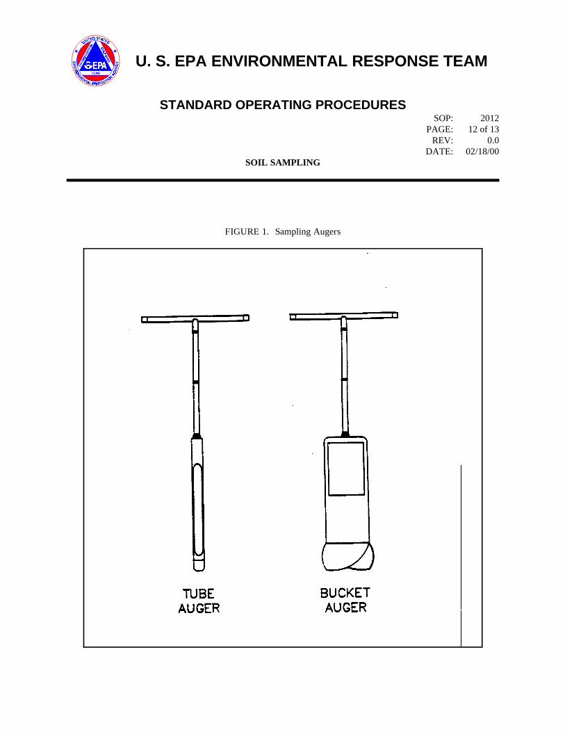
U. S. EPA ENVIRONMENTAL RESPONSE TEAM
STANDARD OPERATING PROCEDURESSOP: 2012
PAGE: 12 of 13REV: 0.0
DATE: 02/18/00SOIL SAMPLING
FIGURE 1. Sampling Augers
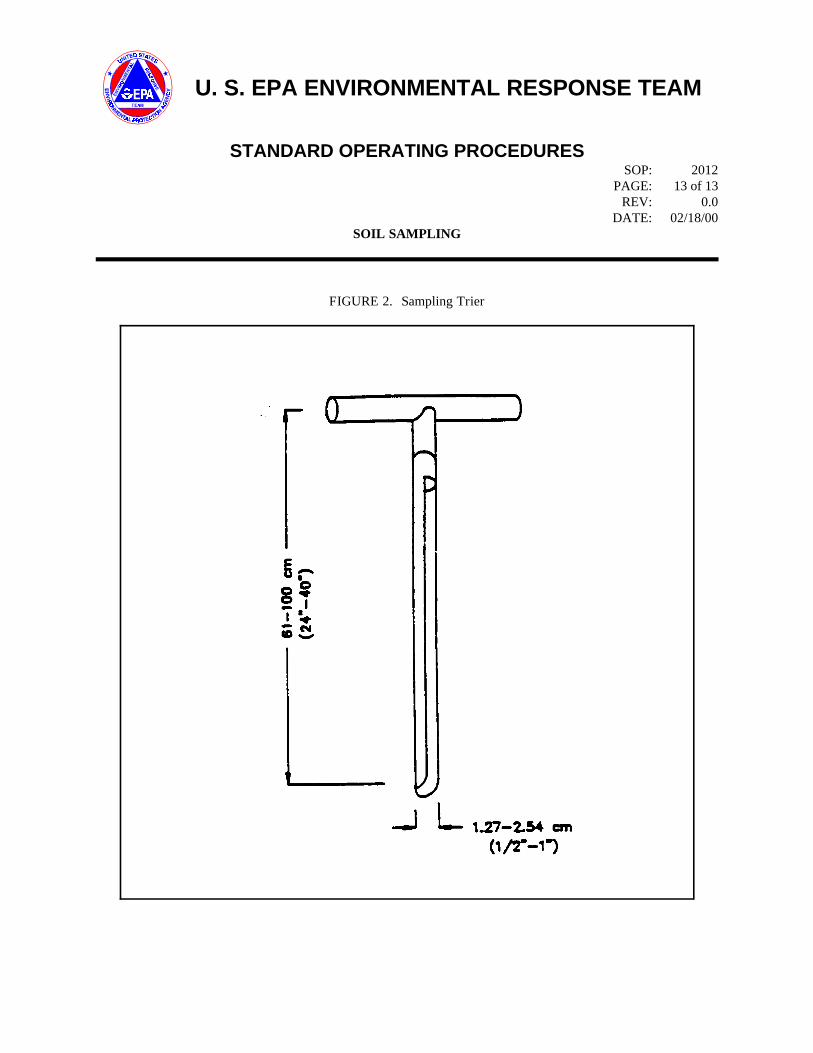
U. S. EPA ENVIRONMENTAL RESPONSE TEAM
STANDARD OPERATING PROCEDURESSOP: 2012
PAGE: 13 of 13REV: 0.0
DATE: 02/18/00SOIL SAMPLING
FIGURE 2. Sampling Trier

1
SOP#: 2013DATE: 11/17/94
REV. #: 0.0 SURFACE WATER SAMPLING
1.0 SCOPE AND APPLICATION 3.0 SAMPLE PRESERVATION,
This standard operating procedure (SOP) is applicableto the collection of representative liquid samples, bothaqueous and non-aqueous from streams, rivers, lakes,ponds, lagoons, and surface impoundments. Itincludes samples collected from depth, as well assamples collected from the surface.
These are standard (i.e., typically applicable)operating procedures which may be varied or changedas required, dependent upon site conditions,equipment limitations or limitations imposed by theprocedure or other procedure limitations. In allinstances, the ultimate procedures employed should bedocumented and associated with the final report.
Mention of trade names or commercial products doesnot constitute U.S. Environmental Protection Agency(EPA) endorsement or recommendation for use.
2.0 METHOD SUMMARY
Sampling situations vary widely, therefore, nouniversal sampling procedure can be recommended.However, sampling of both aqueous and non-aqueousliquids from the above mentioned sources is generallyaccomplished through the use of one of the followingsamplers or techniques:
C Kemmerer bottleC Bacon bomb samplerC Dip samplerC Direct method
These sampling techniques will allow for thecollection of representative samples from the majorityof surface waters and impoundments encountered.
CONTAINERS, HANDLING,AND STORAGE
Once samples have been collected, the followingprocedure should be followed:
1. Transfer the sample(s) into suitable, labeledsample containers.
2. Preserve the sample if appropriate, or usepre-preserved sample bottles. Do not overfillbottles if they are pre-preserved.
3. Cap the container, place in a ziploc plasticbag and cool to 4 C.o
4. Record all pertinent data in the site logbookand on field data sheets.
5. Complete the Chain of Custody record.
6. Attach custody seals to cooler prior toshipment.
7. Decontaminate all sampling equipment priorto the collection of additional samples withthat sampling device.
4.0 INTERFERENCES ANDPOTENTIAL PROBLEMS
There are two primary interferences or potentialproblems with surface water sampling. These includecross contamination of samples and improper samplecollection.
2
1. Cross contamination problems can beeliminated or minimized through the use ofdedicated sampling equipment. If this is notpossible or practical, then decontamination ofsampling equipment is necessary. Refer tothe Sampling Equipment DecontaminationSOP.
2. Improper sample collection can involve usingcontaminated equipment, disturbance of thestream or impoundment substrate, andsampling in an obviously disturbed area.
Following proper decontamination procedures andminimizing disturbance of the sample site willeliminate these problems.
5.0 EQUIPMENT/APPARATUS
Equipment needed for collection of surface watersamples may include (depending on techniquechosen):
C Kemmerer bottlesC Bacon bomb samplerC Dip samplerC Line and messengersC Sample bottles/preservativesC Ziploc bagsC IceC CoolersC Chain of Custody records, custody sealsC Field data sheetsC Decontamination equipmentC Maps/plot planC Safety equipmentC CompassC Tape measureC Survey stakes, flags, or buoys and anchorsC Camera and filmC Logbook/waterproof penC Sample bottle labels
6.0 REAGENTS
Reagents will be utilized for preservation of samplesand for decontamination of sampling equipment. Thepreservatives required are specified by the analysis tobe performed.
7.0 PROCEDURES
7.1 Preparation
1. Determine the extent of the sampling effort,the sampling methods to be employed, andthe types and amounts of equipment andsupplies needed.
2. Obtain the necessary sampling andmonitoring equipment.
3. Decontaminate or pre-clean equipment, andensure that it is in working order.
4. Prepare scheduling and coordinate with staff,clients, and regulatory agency, if appropriate.
5. Perform a general site survey prior to siteentry, in accordance with the site specificHealth and Safety Plan.
6. Use stakes, flagging, or buoys to identify andmark all sampling locations. If required theproposed locations may be adjusted based onsite access, property boundaries, and surfaceobstructions. If collecting sediment samples,this procedure may disturb the bottom.
7.2 Representative SamplingConsiderations
In order to collect a representative sample, thehydrology and morphometrics of a stream orimpoundment should be determined prior to sampling.This will aid in determining the presence of phases orlayers in lagoons, or impoundments, flow patterns instreams, and appropriate sample locations and depths.
Water quality data should be collected inimpoundments, and to determine if stratification ispresent. Measurements of dissolved oxygen, pH, andtemperature can indicate if strata exist which wouldeffect analytical results. Measurements should becollected at one-meter intervals from the substrate tothe surface using the appropriate instrument (i.e., aHydrolab or equivalent).

3
Water quality measurements such as dissolved 3. When the Kemmerer bottle is at the requiredoxygen, pH, temperature, conductivity, and oxidation- depth, send down the messenger, closing thereduction potential can assist in the interpretation of sampling device.analytical data and the selection of sampling sites anddepths when surface water samples are collected. 4. Retrieve the sampler and discharge from the
Generally, the deciding factors in the selection of a potential contamination of the valve.sampling device for sampling liquids in streams, Transfer the sample to the appropriaterivers, lakes, ponds, lagoons, and surface sample container.impoundments are:
1. Will the sample be collected from shore orfrom a boat?
2. What is the desired depth at which you wishto collect the sample?
3. What is the overall depth and flow directionof river or stream?
4. What type of sample will be collected (i.e.,water or lagoon liquids)?
7.2.1 Sampler Composition
The appropriate sampling device must be of a proper sampler.composition. Selection of samplers constructed ofglass, stainless steel, PVC or PFTE (Teflon) should be 3. Transfer the sample to the appropriatebased upon the analyses to be performed. sample container by pulling up on the trigger.
7.3 Sample Collection
7.3.1 Kemmerer Bottle
A Kemmerer bottle (Figure 1, Appendix A) may beused in most situations where site access is from aboat or structure such as a bridge or pier, and wheresamples at depth are required. Sampling proceduresare as follows:
1. Use a properly decontaminated Kemmererbottle. Set the sampling device so that thesampling end pieces (upper and lowerstoppers) are pulled away from the samplingtube (body), allowing the substance to besampled to pass through this tube.
2. Lower the pre-set sampling device to thepredetermined depth. Avoid bottomdisturbance.
bottom drain the first 10-20 mL to clear any
7.3.2 Bacon Bomb Sampler
A bacon bomb sampler (Figure 2, Appendix A) maybe used in situations similar to those outlined for theKemmerer bottle. Sampling procedures are asfollows:
1. Lower the bacon bomb sampler carefully tothe desired depth, allowing the line for thetrigger to remain slack at all times. Whenthe desired depth is reached, pull the triggerline until taut. This will allow the sampler tofill.
2. Release the trigger line and retrieve the
7.3.3 Dip Sampler
A dip sampler (Figure 3, Appendix A) is useful insituations where a sample is to be recovered from anoutfall pipe or along a lagoon bank where directaccess is limited. The long handle on such a deviceallows access from a discrete location. Samplingprocedures are as follows:
1. Assemble the device in accordance with themanufacturer's instructions.
2. Extend the device to the sample location andcollect the sample by dipping the samplerinto the substance.
3. Retrieve the sampler and transfer the sampleto the appropriate sample container.

4
7.3.4 Direct Method
For streams, rivers, lakes, and other surface waters, This section is not applicable to this SOP.the direct method may be utilized to collect watersamples from the surface directly into the samplebottle. This method is not to be used for samplinglagoons or other impoundments where contact withcontaminants is a concern.
Using adequate protective clothing, access thesampling station by appropriate means. For shallowstream stations, collect the sample under the watersurface while pointing the sample container upstream;the container must be upstream of the collector.Avoid disturbing the substrate. For lakes and otherimpoundments, collect the sample under the watersurface avoiding surface debris and the boat wake.
When using the direct method, do not use pre-preserved sample bottles as the collection method maydilute the concentration of preservative necessary forproper sample preservation.
8.0 CALCULATIONS
This section is not applicable to this SOP.
9.0 QUALITY ASSURANCE/QUALITY CONTROL
There are no specific quality assurance (QA) activities U.S. Environmental Protection Agency. 1984.which apply to the implementation of these Characterization of Hazardous Waste Sites - Aprocedures. However, the following general QA Methods Manual: Volume II. Available Samplingprocedures apply: Methods, Second Edition. EPA/600/4-84-076.
1. All data must be documented on field datasheets or within site logbooks.
2. All instrumentation must be operated inaccordance with operating instructions assupplied by the manufacturer, unlessotherwise specified in the work plan.Equipment checkout and calibrationactivities must occur prior tosampling/operation and they must bedocumented.
10.0 DATA VALIDATION
11.0 HEALTH AND SAFETY
When working with potentially hazardous materials,follow U.S. EPA, OSHA and corporate health andsafety procedures.
More specifically, when sampling lagoons or surfaceimpoundments containing known or suspectedhazardous substances, adequate precautions must betaken to ensure the safety of sampling personnel. Thesampling team member collecting the sample shouldnot get too close to the edge of the impoundment,where bank failure may cause him/her to lose his/herbalance. The person performing the sampling shouldbe on a lifeline and be wearing adequate protectiveequipment. When conducting sampling from a boat inan impoundment or flowing waters, appropriateboating safety procedures should be followed.
12.0 REFERENCES
U.S. Geological Survey. 1977. National Handbook orRecommended Methods for Water Data Acquisition.Office of Water Data Coordination Reston, Virginia.(Chapter Updates available).
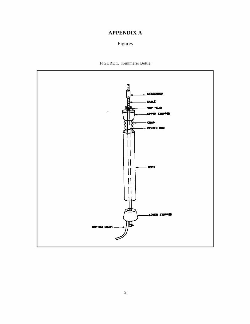
5
APPENDIX A
Figures
FIGURE 1. Kemmerer Bottle
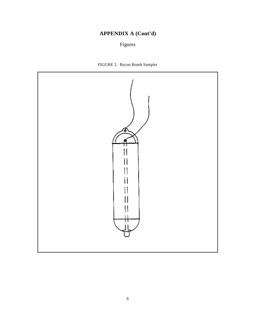
6
APPENDIX A (Cont’d)
Figures
FIGURE 2. Bacon Bomb Sampler

7
APPENDIX A (Cont’d)
Figures
FIGURE 3. Dip Sampler

1
SOP#: 2016DATE: 11/17/94
REV. #: 0.0 SEDIMENT SAMPLING
1.0 SCOPE AND APPLICATION
This standard operating procedure (SOP) is applicableto the collection of representative sediment samples.Analysis of sediment may be biological, chemical, orphysical in nature and may be used to determine thefollowing:
C toxicity;C biological availability and effects of
contaminants;C benthic biota;C extent and magnitude of contamination;C contaminant migration pathways and source;C fate of contaminants;C grain size distribution.
The methodologies discussed in this SOP areapplicable to the sampling of sediment in both flowingand standing water. They are generic in nature andmay be modified in whole or part to meet the handlingand analytical requirements of the contaminants ofconcern, as well as the constraints presented by siteconditions and equipment limitations. However, ifmodifications occur, they should be documented in asite or personal logbook and discussed in reportssummarizing field activities and analytical results.
For the purposes of this procedure, sediments arethose mineral and organic materials situated beneathan aqueous layer. The aqueous layer may be eitherstatic, as in lakes, ponds, and impoundments; orflowing, as in rivers and streams.
Mention of trade names or commercial products doesnot constitute U.S. EPA endorsement orrecommendation for use.
2.0 METHOD SUMMARY
Sediment samples may be collected using a variety ofmethods and equipment, depending on the depth of theaqueous layer, the portion of the sediment profile
required (surface vs. subsurface), the type of samplerequired (disturbed vs. undisturbed), contaminantspresent, and sediment type.
Sediment is collected from beneath an aqueous layereither directly, using a hand held device such as ashovel, trowel, or auger; or indirectly, using aremotely activated device such as an Ekman or Ponardredge. Following collection, sediment is transferredfrom the sampling device to a sample container ofappropriate size and construction for the analysesrequested. If composite sampling techniques areemployed, multiple grabs are placed into a containerconstructed of inert material, homogenized, andtransferred to sample containers appropriate for theanalyses requested. The homogenization procedureshould not be used if sample analysis includes volatileorganics; in this case, sediment, or multiple grabs ofsediment, should be transferred directly from thesample collection device or homogenization containerto the sample container.
3.0 SAMPLE PRESERVATION,CONTAINERS, HANDLING ANDSTORAGE
1. Chemical preservation of solids is generallynot recommended. Cooling to 4 C is usuallyo
the best approach, supplemented by theappropriate holding time for the analysesrequested.
2. Wide mouth glass containers with Teflonlined caps are utilized for sediment samples.The sample volume is a function of theanalytical requirements and will be specifiedin the Work Plan.
3. If analysis of sediment from a discrete depthor location is desired, sediment is transferreddirectly from the sampling device to alabeled sample container(s) of appropriatesize and construction for the analyses

2
requested. Transfer is accomplished with a can, therefore, greatly influence the analytical resultsstainless steel or plastic lab spoon or and should be justified and specified in the Workequivalent. Plan.
4. If composite sampling techniques or multiplegrabs are employed, equal portions ofsediment from each location are depositedinto a stainless steel, plastic, or otherappropriate composition (e.g., Teflon)containers. The sediment is homogenizedthoroughly to obtain a compositerepresentative of the area sampled. Thecomposite sediment sample is transferred toa labeled container(s) of appropriate size andconstruction for the analyses requested.Transfer of sediment is accomplished with astainless steel or plastic lab spoon orequivalent. Samples for volatile organicanalysis must be transferred directly from thesample collection device or pooled frommultiple areas in the homogenizationcontainer prior to mixing. This is done tominimize loss of contaminant due tovolatilization during homogenization.
5. All sampling devices should bedecontaminated, then wrapped in aluminumfoil. The sampling device should remain inthis wrapping until it is needed. Eachsampling device should be used for only onesample. Disposable sampling devices forsediment are generally impractical due tocost and the large number of sedimentsamples which may be required. Samplingdevices should be cleaned in the field usingthe decontamination procedure described inthe Sampling Equipment DecontaminationSOP.
4.0 INTERFERENCES ANDPOTENTIAL PROBLEMS
Substrate particle size and organic matter content area direct consequence of the flow characteristics of awaterbody. Contaminants are more likely to be Reagents are not used for preservation of sedimentconcentrated in sediments typified by fine particle size samples. Decontamination solutions are specified inand a high organic matter content. This type of the Sampling Equipment Decontamination SOP.sediment is most likely to be collected fromdepositional zones. In contrast, coarse sediments withlow organic matter content do not typicallyconcentrate pollutants and are generally found inerosional zones. The selection of a sampling location
5.0 EQUIPMENT/APPARATUS
Equipment needed for collection of sediment samplesmay include:
C Maps/plot planC Safety equipmentC CompassC Tape measureC Survey stakes, flags, or buoys and anchorsC Camera and filmC Stainless steel, plastic, or other appropriate
composition bucketC 4-oz., 8-oz., and one-quart wide mouth jars
w/Teflon lined lidsC Ziploc plastic bagsC LogbookC Sample jar labelsC Chain of Custody records, field data sheetsC Cooler(s)C IceC Decontamination supplies/equipmentC Spade or shovelC SpatulaC ScoopC TrowelC Bucket augerC Tube augerC Extension rodsC "T" handleC Sediment coring device (tube, drive head,
eggshell check value, nosecone, acetate tube,extension rods, "T" handle)
C Ponar dredgeC Ekman dredgeC Nylon rope or steel cableC Messenger device
6.0 REAGENTS

3
7.0 PROCEDURES
7.1 Preparation
1. Determine the objective(s) and extent of thesampling effort. The sampling methods to beemployed, and the types and amounts ofequipment and supplies required will be afunction of site characteristics and objectivesof the study.
2. Obtain the necessary sampling andmonitoring equipment.
3. Prepare schedules, and coordinate with staff,client, and regulatory agencies, ifappropriate.
4. Decontaminate or preclean equipment, andensure that it is in working order.
5. Perform a general site survey prior to siteentry in accordance with the site specificHealth and Safety Plan.
6. Use stakes, flagging, or buoys to identify andmark all sampling locations. Specific sitefactors including flow regime, basinmorphometry, sediment characteristics, depthof overlying aqueous layer, contaminantsource, and extent and nature ofcontamination should be considered whenselecting sample locations. If required, theproposed locations may be adjusted based onsite access, property boundaries, and surfaceobstructions.
7.2 Sample Collection
Selection of a sampling device is most oftencontingent upon: (1) the depth of water at the For the purpose of this method, surface sediment issampling location, and (2) the physical characteristics considered to range from 0 to six inches in depth andof the sediment to be sampled. The following a shallow aqueous layer is considered to range from 0procedures may be utilized: to 24 inches in depth. Collection of surface sediment
7.2.1 Sampling Surface Sediment with aTrowel or Scoop from Beneath aShallow Aqueous Layer
For the purpose of this method, surface sediment isconsidered to range from 0 to six inches in depth and
a shallow aqueous layer is considered to range from 0to 12 inches in depth. Collection of surface sedimentfrom beneath a shallow aqueous layer can beaccomplished with tools such as spades, shovels,trowels, and scoops. Although this method can beused to collect both unconsolidated/consolidatedsediment, it is limited somewhat by the depth andmovement of the aqueous layer. Deep and rapidlyflowing water render this method less accurate thanothers discussed below. However, representativesamples can be collected with this procedure inshallow sluggish water provided care is demonstratedby the sample team member. A stainless steel orplastic sampling implement will suffice in mostapplications. Care should be exercised to avoid theuse of devices plated with chrome or other materials;plating is particularly common with garden trowels.
The following procedure will be used to collectsediment with a scoop, shovel, or trowel:
1. Using a decontaminated samplingimplement, remove the desired thickness andvolume of sediment from the sampling area.
2. Transfer the sample into an appropriatesample or homogenization container. Ensurethat non-dedicated containers have beenadequately decontaminated.
3. Surface water should be decanted from thesample or homogenization container prior tosealing or transfer; care should be taken toretain the fine sediment fraction during thisprocedure.
7.2.2 Sampling Surface Sediment with aBucket Auger or Tube Auger fromBeneath a Shallow Aqueous Layer
from beneath a shallow aqueous layer can beaccomplished with a system consisting of bucketauger or tube auger, a series of extensions, and a "T"handle (Figure 1, Appendix A). The use of additionalextensions in conjunction with a bucket auger canincrease the depth of water from which sediment canbe collected from 24 inches to 10 feet or more.However, sample handling and manipulation increases

4
in difficulty with increasing depth of water. The "T" handle. The use of additional extensions canbucket auger or tube auger is driven into the sediment increase the depth of water from which sediment canand used to extract a core. The various depths be collected from 24 inches to five feet or more.represented by the core are homogenized or a However, water clarity must be high enough to permitsubsample of the core is taken from the appropriate the sampler to directly observe the samplingdepth. operation. In addition, sample handling and
The following procedure will be used to collect depth of water. The bucket auger is used to bore asediment samples with a bucket auger or tube auger: hole to the upper range of the desired sampling depth
1. An acetate core may be inserted into the down the borehole, and driven into the sediment to thebucket auger or tube auger prior to sampling lower range of the desired sampling depth. The tubeif characteristics of the sediments or is then withdrawn and the sample recovered from thewaterbody warrant. By using this technique, tube. This method can be used to collect firmlyan intact core can be extracted. consolidated sediments, but is somewhat limited by
2. Attach the auger head to the required length initial borehole.of extensions, then attach the "T" handle tothe upper extension. The following procedure will be used to collect deep
3. Clear the area to be sampled of any surface auger:debris.
4. Insert the bucket auger or tube auger into the lengths of extensions, then attach the "T"sediment at a 0 to 20 angle from vertical. handle to the upper extension.o o
This orientation minimizes spillage of thesample from the sampler upon extraction 2. Clear the area to be sampled of any surfacefrom the sediment and water. debris.
5. Rotate the auger to cut a core of sediment. 3. Begin augering, periodically removing any
6. Slowly withdraw the auger; if using a tube the auger bucket. Cuttings should beauger, make sure that the slot is facing disposed of far enough from the samplingupward. area to minimize cross contamination of
7. Transfer the sample or a specified aliquot ofsample into an appropriate sample or 4. After reaching the upper range of the desiredhomogenization container. Ensure that non- depth, slowly and carefully remove bucketdedicated containers have been adequately auger from the boring.decontaminated.
7.2.3 Sampling Deep Sediment with aBucket Auger or Tube Auger fromBeneath a Shallow Aqueous Layer
For the purpose of this method, deep sediment isconsidered to range from six to greater than 18 inchesin depth and a shallow aqueous layer is considered torange from 0 to 24 inches. Collection of deepsediment from beneath a shallow aqueous layer can beaccomplished with a system consisting of a bucketauger, a tube auger, a series of extensions and a
manipulation increases in difficulty with increasing
and then withdrawn. The tube auger is then lowered
the depth of the aqueous layer, and the integrity of the
sediment samples with a bucket auger and a tube
1. Attach the bucket auger bit to the required
accumulated sediment (i.e., cuttings) from
various depths.
5. Attach the tube auger bit to the requiredlengths of extensions, then attach the "T"handle to the upper extension.
6. Carefully lower tube auger down boreholeusing care to avoid making contact with theborehole sides and, thus, cross contaminatingthe sample. Gradually force tube auger intosediment to the lower range of the desiredsampling depth. Hammering of the tubeauger to facilitate coring should be avoidedas the vibrations may cause the boring walls
5
to collapse. above the sediment surface.
7. Remove tube auger from the borehole, again 4. Drop the sampler to the sediment.taking care to avoid making contact with theborehole sides and, thus, cross contaminating 5. Trigger the jaw release mechanism bythe sample. lowering a messenger down the line, or by
8. Discard the top of core (approximately 1 extension handle.inch); as this represents material collected bythe tube auger before penetration to the layer 6. Raise the sampler and slowly decant any freeof concern. liquid through the top of the sampler. Care
9. Transfer sample into an appropriate sample fraction during this procedure.or homogenization container. Ensure thatnon-dedicated containers have been 7. Open the dredge jaws and transfer the sampleadequately decontaminated. into a stainless steel, plastic or other
7.2.4 Sampling Surface Sediment with anEkman or Ponar Dredge fromBeneath a Shallow or Deep AqueousLayer
For the purpose of this method, surface sediment isconsidered to range from 0 to six inches in depth.Collection of surface sediment can be accomplishedwith a system consisting of a remotely activateddevice (dredge) and a deployment system. Thistechnique consists of lowering a sampling device(dredge) to the surface of the sediment by use of arope, cable, or extended handle. The mechanism isactivated, and the device entraps sediment in springloaded or lever operated jaws.
An Ekman dredge is a lightweight sediment samplingdevice with spring activated jaws. It is used to collectmoderately consolidated, fine textured sediment. Thefollowing procedure will be used for collectingsediment with an Ekman dredge (Figure 2,Appendix A):
1. Attach a sturdy nylon rope or stainless steelcable through the hole on the top of thebracket, or secure the extension handle to thebracket with machine bolts.
2. Attach springs to both sides of the jaws. Fixthe jaws so that they are in open position byplacing trip cables over the release studs.Ensure that the hinged doors on the dredgetop are free to open.
3. Lower the sampler to a point 4 to 6 inches
depressing the button on the upper end of the
should be taken to retain the fine sediment
appropriate composition (e.g., Teflon)container. Ensure that non-dedicatedcontainers have been adequatelydecontaminated. If necessary, continue tocollect additional sediment grabs untilsufficient material has been secured to fulfillanalytical requirements. Thoroughlyhomogenize and then transfer sediment tosample containers appropriate for theanalyses requested. Samples for volatileorganic analysis must be collected directlyfrom the bucket before homogenization tominimize volatilization of contaminants.
A Ponar dredge is a heavyweight sediment samplingdevice with weighted jaws that are lever or springactivated. It is used to collect consolidated fine tocoarse textured sediment. The following procedurewill be used for collecting sediment with a Ponardredge (Figure 3, Appendix A):
1. Attach a sturdy nylon rope or steel cable tothe ring provided on top of the dredge.
2. Arrange the Ponar dredge with the jaws inthe open position, setting the trip bar so thesampler remains open when lifted from thetop. If the dredge is so equipped, place thespring loaded pin into the aligned holes in thetrip bar.
3. Slowly lower the sampler to a pointapproximately two inches above thesediment.
4. Drop the sampler to the sediment. Slack on
6
the line will release the trip bar or spring 2. Insert the "egg shell" check valve into theloaded pin; pull up sharply on the line lower end of the sampling tube with theclosing the dredge. convex surface positioned inside the acetate
5. Raise the dredge to the surface and slowlydecant any free liquid through the screens on 3. Screw the nosecone onto the lower end of thetop of the dredge. Care should be taken to sampling tube, securing the acetate tube andretain the fine sediment fraction during this eggshell check valve.operation.
6. Open the dredge and transfer the sediment to sampling tube and add extension rods asa stainless steel, plastic or other appropriate needed.composition (e.g., Teflon) container. Ensurethat non-dedicated containers have been 5. Place the sampler in a perpendicular positionadequately decontaminated. If necessary, on the sediment to be sampled.continue to collect additional sediment untilsufficient material has been secured to fulfill 6. If the "T" handle is used, place downwardanalytical requirements. Thoroughly pressure on the device until the desired depthhomogenized and then transfer sediment to is reached. After the desired depth issample containers appropriate for the reached, rotate the sampler to shear off theanalyses requested. Samples for volatile core at the bottom. Slowly withdraw theorganic analysis must be collected directly sampler from the sediment and proceed tofrom the bucket before homogenization to Step 15.minimize volatilization of contaminants.
7.2.5 Sampling Subsurface Sediment witha Coring Device from Beneath aShallow Aqueous Layer
For purposes of this method, subsurface sediment isconsidered to range from 6 to 24 inches in depth anda shallow aqueous layer is considered to range from 0to 24 inches in depth. Collection of subsurfacesediment from beneath a shallow aqueous layer can beaccomplished with a system consisting of a tubesampler, acetate tube, eggshell check valve, nosecone,extensions, and "T" handle, or drivehead. The use ofadditional extensions can increase the depth of waterfrom which sediment can be collected from 24 inchesto 10 feet or more. This sampler may be used witheither a drive hammer for firm sediment, or a "T"handle for soft sediment. However, sample handlingand manipulation increases in difficulty withincreasing depth of water.
The following procedure describes the use of a samplecoring device (Figure 4, Appendix A) used to collectsubsurface sediments.
1. Assemble the coring device by inserting theacetate core into the sampling tube.
core.
4. Screw the handle onto the upper end of the
7. If the drive hammer is selected, insert thetapered handle (drive head) of the drivehammer through the drive head.
8. Drive the sampler into the sediment to thedesired depth.
9. Record the length of the tube that penetratedthe sample material, and the number ofblows required to obtain this depth.
10. Remove the drive hammer and fit thekeyhole-like opening on the flat side of thehammer onto the drive head. In this position,the hammer serves as a handle for thesampler.
11. Rotate the sampler to shear off the core at thebottom.
12. Lower the sampler handle (hammer) until itjust clears the two ear-like protrusions on thedrive head, and rotate about 90 .o
13. Slowly withdraw the sampler from thesediment. If the drivehead was used, pull thehammer upwards and dislodge the samplerfrom the sediment.
7
14. Carefully remove the coring device from the 2. All instrumentation must be operated inwater. accordance with operating instructions as
15. Unscrew the nosecone and remove the otherwise specified in the work plan.eggshell check valve. Equipment checkout and calibration
16. Slide the acetate core out of the sampler sampling/operation, and they must betube. Decant surface water, using care to documented.retain the fine sediment fraction. If headspace is present in the upper end, a hacksawmay be used to shear the acetate tube off atthe sediment surface. The acetate core maythen be capped at both ends. Indicate on theacetate tube the appropriate orientation of thesediment core using a waterproof marker.The sample may be used in this fashion, orthe contents transferred to a sample orhomogenization container.
17. Open the acetate tube and transfer thesediment to a stainless steel, plastic or otherappropriate composition (e.g., Teflon)container. Ensure that non-dedicatedcontainers have been adequatelydecontaminated. If necessary, continue tocollect additional sediment until sufficientmaterial has been secured to fulfill analyticalrequirements. Thoroughly homogenize andthen transfer sediment to sample containersappropriate for the analyses requested.Samples for volatile organic analysis must becollected directly from the bucket beforehomogenization to minimize volatilization ofcontaminants.
8.0 CALCULATIONS
This section is not applicable to this SOP.
9.0 QUALITY ASSURANCE/QUALITY CONTROL
There are no specific quality assurance (QA) activities 600/4-84-076.which apply to the implementation of theseprocedures. However, the following QA procedures de Vera, E.R., B.P. Simmons, R.D. Stephen, and D.L.apply: Storm. Samplers and Sampling Procedures for
1. All data must be documented on field datasheets or within site logbooks.
supplied by the manufacturer, unless
activities must occur prior to
10.0 DATA VALIDATION
This section is not applicable to this SOP.
11.0 HEALTH AND SAFETY
When working with potentially hazardous materials ,follow U.S. EPA/OSHA and Corporate health andsafety procedures.
More specifically, when sampling sediment fromwaterbodies, physical hazards must be identified andadequate precautions must be taken to ensure thesafety of the sampling team. The team membercollecting the sample should not get too close to theedge of the waterbody, where bank failure may causeloss of balance. To prevent this, the personperforming the sampling should be on a lifeline, andbe wearing adequate protective equipment. Ifsampling from a vessel is determined to be necessary,appropriate protective measures must be implemented.
12.0 REFERENCES
Mason, B.J., Preparation of Soil Sampling Protocol:Technique and Strategies. 1983 EPA-600/4-83-020.
Barth, D.S. and B.J. Mason, Soil Sampling QualityAssurance User's Guide. 1984 EPA-600/4-84-043.
U.S. EPA. Characterization of Hazardous Waste Sites- A Methods Manual: Volume II. AvailableSampling Methods, Second Edition. 1984 EPA-
Hazardous Waste Streams. 1980 EPA-600/2-80-018.

8
APPENDIX A
Figures
FIGURE 1. Sampling Auger
TUBE AUGER
ill
D ~ - -
BUCKET AUGER

9
APPENDIX A (Cont’d)
Figures
FIGURE 2. Ekman Dredge
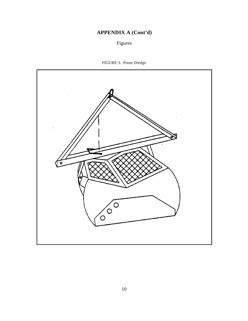
10
APPENDIX A (Cont’d)
Figures
FIGURE 3. Ponar Dredge
o o
o
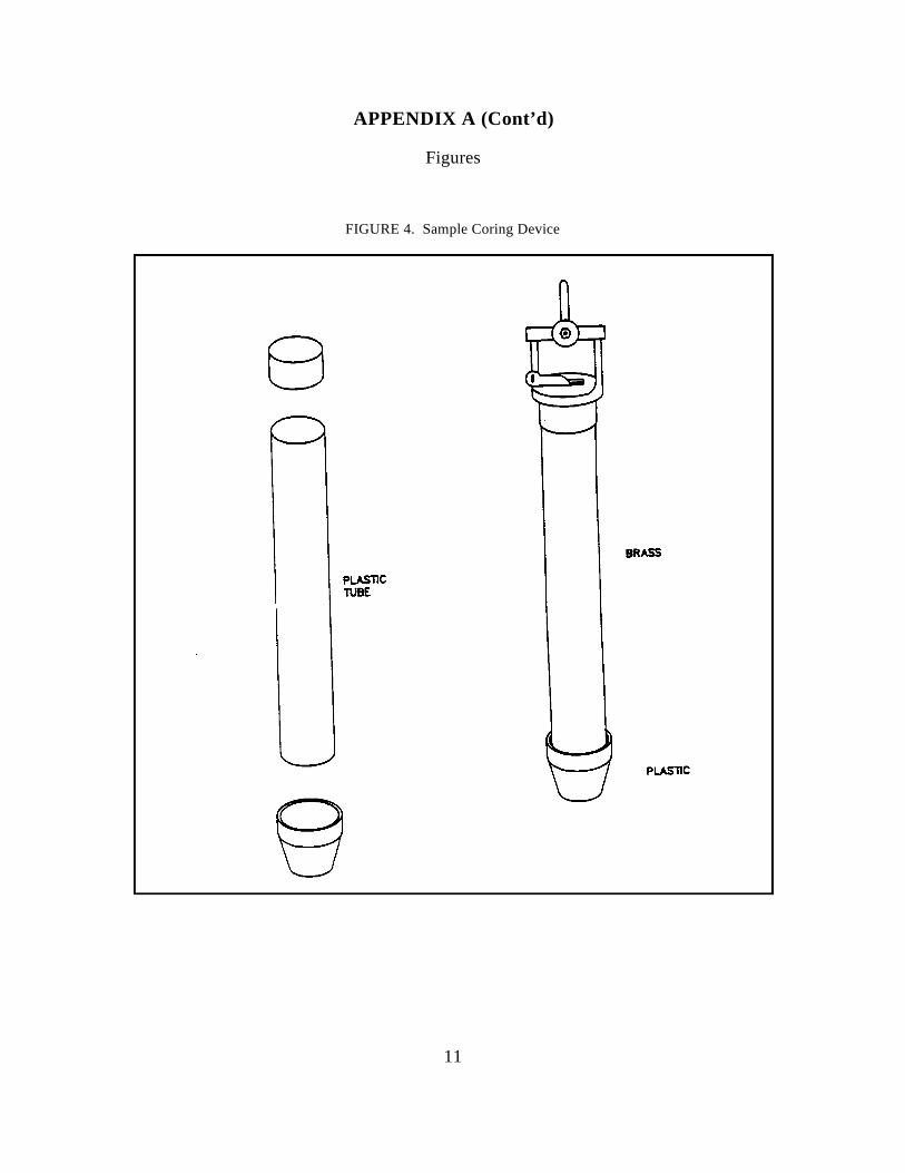
11
APPENDIX A (Cont’d)
Figures
FIGURE 4. Sample Coring Device
8
PLASllC lUBE
BRASS
PLASllC

U. S. EPA ENVIRONMENTAL RESPONSE TEAM
STANDARD OPERATING PROCEDURESSOP: 2043
PAGE: 1 of 10REV: 0.0
DATE: 02/11/00MANUAL WATER LEVEL MEASUREMENTS
CONTENTS
1.0 SCOPE AND APPLICATION
2.0 METHOD SUMMARY
3.0 SAMPLE PRESERVATION, CONTAINERS, HANDLING AND STORAGE
4.0 POTENTIAL PROBLEMS
5.0 EQUIPMENT
6.0 REAGENTS
7.0 PROCEDURES
7.1 Preparation7.2 Procedures
8.0 CALCULATIONS
9.0 QUALITY ASSURANCE/QUALITY CONTROL
10. DATA VALIDATION
11.0 HEALTH AND SAFETY
12.0 REFERENCES
13.0 APPENDIX
A - Groundwater Level Data Form
SUPERCEDES: SOP #2043; Revision 0.0; 10/03/94; U.S. EPA Contract 68-C4-0022.

U. S. EPA ENVIRONMENTAL RESPONSE TEAM
STANDARD OPERATING PROCEDURESSOP: 2043
PAGE: 2 of 10REV: 0.0
DATE: 02/11/00MANUAL WATER LEVEL MEASUREMENTS
1.0 SCOPE AND APPLICATION
The purpose of this Standard Operating Procedure (SOP) is to set guidelines for the determination of thedepth to water and separate phase chemical product (i.e., gasoline, oil, PCE, TCE) in an open borehole,cased borehole, monitor well, or piezometer. These standard operating procedures may be varied orchanged as required, dependent on site conditions , and equipment limitations. In all instances, the actualprocedures employed will be documented and described in an appropriate site report. Mention of tradenames or commercial products does not constitute U.S. EPA endorsement or recommendation for use.
Generally, water-level measurements taken in boreholes, piezometers, or monitor wells are used toconstruct water table or potentiometric surface maps and to determine flow direction as well as otheraquifer characteristics. Therefore, all water level measurements at a given site should preferably becollected within a 24 hour period. However, certain situations may produce rapidly changing groundwaterlevels that necessitate taking measurements as close in time as possible. Large changes in water levelsamong wells may be indicative of such a condition . Rapid groundwater level changes may occur due to:
! Atmospheric pressure changes
! Tidal influences
! Changes in river stage, impoundments levels, or flow in unlined ditches
! Pumping of nearby wells
! Precipitation
2.0 METHOD SUMMARY
A survey mark should be placed on the top of the riser pipe or casing as a reference point for groundwaterlevel measurements. If the lip of the riser pipe is not flat, the reference point may be located on the groutapron or the top of the outer protective casing (if present). The measurement reference point should bedocumented in the site logbook and on the groundwater level data form (Appendix A), if used. All fieldpersonnel must be made aware of the measurement reference point being used in order to ensure thecollection of comparable data.
Before measurements are made, water levels in piezometers and monitor wells should be allowed tostabilize for a minimum of 24 hours after well construction and development. In low yield situations,recovery of water levels to equilibrium may take longer. All measurements should be made to an accuracyof 0.01 feet. Water level measuring equipment must be decontaminated and, in general, measurementsshould proceed from the least to the most contaminated wells.

U. S. EPA ENVIRONMENTAL RESPONSE TEAM
STANDARD OPERATING PROCEDURESSOP: 2043
PAGE: 3 of 10REV: 0.0
DATE: 02/11/00MANUAL WATER LEVEL MEASUREMENTS
Open the well and monitor the headspace with the appropriate air monitoring instrument to determine thepresence of volatile organic compounds. For electrical sounders lower the device into the well until thewater surface is reached as indicated by a tone or meter deflection. Record the distance from the watersurface to the reference point. Measurement with a chalked tape will necessitate lowering the tape belowthe water level and holding a convenient foot marker at the reference point. Record both the water levelas indicated on the chalked tape section and the depth mark held at the reference point The depth to wateris the difference between the two readings. Remove measuring device, replace riser pipe cap, anddecontaminate equipment as necessary. Note that if a separate phase is present, an oil/water indicatorprobe is required for measurement of product thickness and water level.
3.0 SAMPLE PRESERVATION, CONTAINERS, HANDLING AND STORAGE
This section is not applicable to this standard operating procedure (SOP).
4.0 POTENTIAL PROBLEMS
1. Cascading water, particularly in open-hole or rock wells, may interfere with themeasurement.
2. Some older types of electric sounders are only marked at five-foot intervals. A surveyor’stape is necessary to extrapolate between the 5-foot marks.
3. Oil or other product floating on the water column can insulate the contacts of the probeon an electric sounder and give false readings. For accurate level measurements in wellscontaining floating product, a special oil/water level indicator is required.
4. Tapes (electrical or surveyor’s) may have damaged or missing sections, or may be splicedinaccurately.
5. An airline may be the only available means to make measurements in sealed productionwells but the method is generally accurate only to approximately 0.2 foot.
6. When using a steel tape, it is necessary to lower the tape below the water level in orderto make a measurement. This assumes knowledge of the approximate groundwater level.
5.0 EQUIPMENT
The electric water level indicator and the chalked steel tape are the devices commonly used to measurewater levels. Both have an accuracy of 0.01 feet. Other field equipment may include:
C Air monitoring instrumentation

U. S. EPA ENVIRONMENTAL RESPONSE TEAM
STANDARD OPERATING PROCEDURESSOP: 2043
PAGE: 4 of 10REV: 0.0
DATE: 02/11/00MANUAL WATER LEVEL MEASUREMENTS
C Well depth measurement device
C Chalk
C Ruler
C Site logbook
C Paper towels and trash bags
C Decontamination supplies as outlined in Section 7.2 or the current approved site specificwork plan
C Groundwater level data forms
6.0 REAGENTS
No chemical reagents are used in this procedure; however, decontamination solutions may be necessary.If decontamination of equipment is required, refer to ERT/REAC SOP #2006 Rev 0.0 08/11/94, SamplingEquipment Decontamination, and the current approved site specific work plan.
7.0 PROCEDURES
7.1 Preparation
1. Determine the number of measurements needed, the methods to be employed, and theequipment and supplies needed.
2. Decontaminate or pre-clean equipment, and ensure that it is in working order.
3. Coordinate schedule with staff, clients, and regulatory agency, if appropriate.
4. If this is an initial visit, perform a general site survey prior to site entry in accordancewith the current approved site specific Health and Safety Plan.
5. Identify sampling locations.

U. S. EPA ENVIRONMENTAL RESPONSE TEAM
STANDARD OPERATING PROCEDURESSOP: 2043
PAGE: 5 of 10REV: 0.0
DATE: 02/11/00MANUAL WATER LEVEL MEASUREMENTS
7.2 Procedures
Procedures for determining water levels are as follows:
1. If possible, and when applicable, start at those wells that are least contaminated andproceed to those wells that are most contaminated.
2. Clean all the equipment entering the well(s) by the following decontamination procedure:
C Triple rinse equipment with deionized water.
C Wash equipment with an Alconox solution which is followed by a deionizedwater rinse.
C Rinse with an approved solvent (e.g., methanol, isopropyl alcohol, acetone) asper the work plan, if organic contamination is suspected.
C Place equipment on clean surface such as a teflon or polyethylene sheet to airdry.
3. Remove locking well cap, note well ID, time of day, and date in site logbook or anappropriate groundwater level data form.
4. Remove well cap.
5. If required by site-specific condition, monitor headspace of well with a photoionizationdetector (PID) or flame ionization detector (FID) to determine presence of volatileorganic compounds, and record results in site logbook.
7. Lower water-level measuring device into the well. Electrical tapes are lowered to thewater surface whereas chalked steel tapes are lowered generally a foot or more below thewater surface. Steel tapes are generally chalked so that a 1-to 5-foot long section will fallbelow the expected water level.
8. For electrical tapes record the distance from the water surface, as determined by theaudio signal or meter, to the reference measuring point and record in the site logbook.For chalked tapes, an even foot mark is held at the reference point, once the chalkedsection of the tape is below the water level. Both the water level on the tape and the footmark held at the reference point is recorded. The depth to the water is then thedifference between the two readings. In addition, note the reference point used (top of theouter casing, top of the riser pipe, ground surface, or some other reproducible position
U. S. EPA ENVIRONMENTAL RESPONSE TEAM
STANDARD OPERATING PROCEDURESSOP: 2043
PAGE: 6 of 10REV: 0.0
DATE: 02/11/00MANUAL WATER LEVEL MEASUREMENTS
EW '' E && D
on the well head). Repeat the measurement.
9. Remove all downhole equipment, replace well cap and locking steel caps.
10. Rinse all downhole equipment and store for transport to the next well. Decontaminateall equipment as outlined in Step 2 above.
11. Note any physical changes, such as erosion or cracks in protective concrete pad orvariation in total depth of well, in field logbook or on groundwater level data form.
8.0 CALCULATIONS
To determine groundwater elevation above mean sea level, use the following equation:
where:
EW = Elevation of water above mean sea level (feet) or local datumE = Elevation above sea level or local datum at point of measurement (feet)D = Depth to water (feet)
9.0 QUALITY ASSURANCE/QUALITY CONTROL
The following general quality assurance/quality control (QA/QC) procedures apply:
1. All data must be documented on field data sheets, groundwater level data forms, or withinpersonal or site logbooks.
2. All instrumentation must be operated in accordance with operating instructions as supplied by themanufacturer, unless otherwise specified in the work plan.
3. Each well should be tested at least twice in order to compare results. If results do not agree towithin 0.02 feet, a third measurement should be taken and the readings averaged. Consistentfailure of consecutive readings to agree suggests that levels are changing because of one or moreconditions as indicated in Section 1.
10.0 DATA VALIDATION
This section is not applicable to this SOP.
U. S. EPA ENVIRONMENTAL RESPONSE TEAM
STANDARD OPERATING PROCEDURESSOP: 2043
PAGE: 7 of 10REV: 0.0
DATE: 02/11/00MANUAL WATER LEVEL MEASUREMENTS
11.0 HEALTH AND SAFETY
The results of monitoring the well head and breathing zone with a FID or PID, as per section 7.2, mayindicate the need to upgrade the personal protection level according to the current approved site Health andSafety Plan.
12.0 REFERENCES
Driscoll, F.G. 1986. Groundwater and Wells. Second Edition. Chapter 16. Collection and Analysis ofPumping Test Data. pp 534-579. Johnson Filtration Systems Inc. St. Paul, Minnesota.
U.S. Environmental Protection Agency, 1986. RCRA Groundwater Monitoring Technical EnforcementGuidance Document, pp. 207.
U.S. Environmental Protection Agency, 1987, A Compendium of Superfund Field Operations Methods.EPA/540/p-87/001 Office of Emergency and Remedial Response Washington, D.C. 20460.
U. S. EPA ENVIRONMENTAL RESPONSE TEAM
STANDARD OPERATING PROCEDURESSOP: 2043
PAGE: 8 of 10REV: 0.0
DATE: 02/11/00MANUAL WATER LEVEL MEASUREMENTS
APPENDIX AGroundwater Level Data Form
SOP #2043February 2000
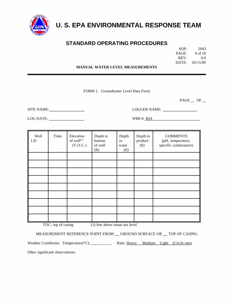
U. S. EPA ENVIRONMENTAL RESPONSE TEAM
STANDARD OPERATING PROCEDURESSOP: 2043
PAGE: 9 of 10REV: 0.0
DATE: 02/11/00MANUAL WATER LEVEL MEASUREMENTS
FORM 1. Groundwater Level Data Form
PAGE OF
SITE NAME: LOGGER NAME:
LOG DATE: WBS #: RIA
WellI.D.
Time Elevationof well(1)
(T.O.C.)
Depth tobottom of well (ft)
Depthtowater (ft)
Depth toproduct (ft)
COMMENTS(pH, temperature,
specific conductance)
TOC: top of casing (1) feet above mean sea level
MEASUREMENT REFERENCE POINT FROM GROUND SURFACE OR TOP OF CASING
Weather Conditions: Temperature(oC):___________ Rain: Heavy Medium Light (Circle one)
Other significant observations:

U. S. EPA ENVIRONMENTAL RESPONSE TEAM
STANDARD OPERATING PROCEDURESSOP: 2044
PAGE: 1 of 8REV: 0.1
DATE: 10/23/01MONITOR WELL DEVELOPMENT
CONTENTS
1.0 SCOPE AND APPLICATION*
2.0 METHOD SUMMARY*
3.0 SAMPLE PRESERVATION, CONTAINERS, HANDLING, AND STORAGE
4.0 INTERFERENCES AND POTENTIAL PROBLEMS*
5.0 EQUIPMENT/APPARATUS*
6.0 REAGENTS
7.0 PROCEDURES
7.1 Preparation7.2 Operation*7.3 Post-Operation
8.0 CALCULATIONS*
9.0 QUALITY ASSURANCE/QUALITY CONTROL*
10.0 DATA VALIDATION
11.0 HEALTH AND SAFETY
12.0 REFERENCES*
13.0 APPENDICES*
*These sections affected by Revision 0.1.
SUPERCEDES: SOP #2044; Revision 0.0; 2/18/00; U.S. EPA Contract 68-C99-223.
U. S. EPA ENVIRONMENTAL RESPONSE TEAM
STANDARD OPERATING PROCEDURESSOP: 2044
PAGE: 2 of 8REV: 0.1
DATE: 10/23/01MONITOR WELL DEVELOPMENT
1.0 SCOPE AND APPLICATION
The purpose of this standard operating procedure (SOP) is to provide an overview of monitor well developmentpractices. The purpose of monitor well development is to ensure removal of fine grained sediments (fines) fromthe vicinity of the well screen. This allows the water to flow freely from the formation into the well, and alsoreduces the turbidity of the water during sampling. The most common well development methods are: surging,jetting, overpumping, and bailing.
Surging involves raising and lowering a surge block or surge plunger inside the well. The resulting surgingmotion forces water into the formation and loosens sediment, pulled from the formation into the well.Occasionally, sediments must be removed from the well with a sand bailer to prevent sand locking of the surgeblock. This method may cause the sand pack around the screen to be displaced to a degree that damages itsvalue as a filtering medium. Channels or voids may form near the screen if the filter pack sloughs away duringsurging (Keel and Boating, 1987).
Surging with compressed air is done by injecting a sudden charge of compressed air into the well with an airline so that water is forced through the well screen. The air is then turned off so that the water column falls backinto the well and the process is repeated. Periodically, the air line is pulled up into a pipe string (educator) andwater is pumped from the well using air as the lifting medium (air-lift pumping). The process is repeated untilthe well is sediment free. Method variations include leaving the air line in the pipe string at all times or usingthe well casing as the educator pipe.
Jetting involves lowering a small diameter pipe into the well and injecting a high velocity horizontal stream ofwater or air through the pipe into the screen openings. This method is especially effective at breaking downfilter cakes developed during mud rotary drilling. Simultaneous air-lift pumping is usually used to remove fines.
Overpumping involves pumping at a rate rapid enough to draw the water level in the well as low as possible,and then allowing the well to recharge to the original level. This process is repeated until sediment-free wateris produced.
Bailing includes the use of a simple manually operated check-valve bailer to remove water from the well. Thebailing method, like other methods, should be repeated until sediment free water is produced. Bailing may bethe method of choice in a shallow well or well that recharges slowly.
These are standard (i.e., typically applicable) operating procedures which may be varied or changed as required,dependent on site conditions, equipment limitations or limitations imposed by the procedure. In all instances,the ultimate procedures employed should be documented and associated with a final report.
Mention of trade names or commercial products does not constitute United States Environmental Protection
U. S. EPA ENVIRONMENTAL RESPONSE TEAM
STANDARD OPERATING PROCEDURESSOP: 2044
PAGE: 3 of 8REV: 0.1
DATE: 10/23/01MONITOR WELL DEVELOPMENT
Agency (U.S. EPA) endorsement or recommendation for use.
2.0 METHOD SUMMARY
After installation, development of a well should occur as soon as it is practical. It should not occur any soonerthan 48 hours after grouting is completed, especially if a vigorous well development method (i.e. surging) isbeing used. If a less vigorous method (i.e bailing) is used, it may be initiated shortly after installation. Themethod used for development should not interfere with the setting of the well seal.
Several activities must take place prior to well development. First, open the monitor well, take initialmeasurements (i.e., head space air monitoring readings, water level, total depth of the well) and record resultsin the site logbook. Develop the well by the appropriate method to accommodate site conditions and projectobjectives. Continue until the development water is clear and free of sediments, or until parameters such as pH,temperature, and specific conductivity stabilize. Containerize all purge water from wells with known orsuspected contamination. Record final measurements in the site logbook. Decontaminate equipment asappropriate prior to use in the next well.
3.0 SAMPLE PRESERVATION, CONTAINERS, HANDLING, AND STORAGE
This section is not applicable to this SOP.
4.0 INTERFERENCES AND POTENTIAL PROBLEMS
The following problems may be associated with well development:
1. Overpumping is not as vigorous as surging and jetting, and is probably the most desirable methodfor monitor well development. The possibility of disturbing the filter pack is greatest with surging andjetting well development methods.
2. The introduction of external water or air by jetting may alter the hydro chemistry of the aquifer.
3. Surging with air may produce “air locking” in some formations, preventing water from flowing intothe well.
4. The use of surge blocks in formations containing clay may cause plugging of the screen.
5. Small (2-inch nominal diameter) submersible pumps that will fit in 2-inch diameter well casing are especially susceptible to clogging if used in well development applications.
6. Chemicals/reagents used during the decontamination of drilling equipment may complicate welldevelopment.
U. S. EPA ENVIRONMENTAL RESPONSE TEAM
STANDARD OPERATING PROCEDURESSOP: 2044
PAGE: 4 of 8REV: 0.1
DATE: 10/23/01MONITOR WELL DEVELOPMENT
5.0 EQUIPMENT/APPARATUS
The type of equipment used for well development is dependent on the diameter of the well and the developmentmethod. For example, the diameter of most submersible pumps is too large to fit into a two-inch inner diameter(I.D.) well, and other development methods should be used. Obtaining the highest possible yield is not usuallyan objective in developing monitor wells and vigorous development is not always necessary. Many monitorwells are constructed in fine-grained formations that would not normally be considered aquifers. Specificationsfor the drilling contract should include the necessary well development equipment (air compressors, pumps,air lines, surge blocks, generators).
6.0 REAGENTS
The use of chemicals in developing wells that will be used to monitor groundwater quality should be avoidedif possible; however, polyphosphates (a dispersing agent), acids, or disinfectants are often used in general welldevelopment. Polyphosphates should not be used in thinly bedded sequences of sands and clays. The useof decontamination solutions may also be necessary. If decontamination of equipment is required at a well,refer to Environmental Response Team/Response Engineering and Analytical Contract (ERT/REAC) SOP #2006,Sampling Equipment Decontamination and the site specific work plan.
7.0 PROCEDURES
7.1 Preparation
1. Coordinate site access and obtain keys to well locks.
2. Obtain information on each well to be developed (i.e., drilling method, well diameter, welldepth, screened interval, anticipated contaminants).
3. Obtain a water level meter, a depth sounder, air monitoring instruments, materials fordecontamination, and water quality instrumentation capable of measuring, at a minimum, pH,specific conductivity, temperature, and turbidity. Dissolved oxygen (DO) and salinity arealso useful parameters.
4. Assemble containers for temporary storage of water produced during well development.Containers must be structurally sound, compatible with anticipated contaminant s, and easyto manage in the field. The use of truck-mounted or roll-off tanks may be necessary in somecases; alternately, a portable water treatment unit (i.e., activated carbon) may be used todecontaminate the purge water.
7.2 Operation
U. S. EPA ENVIRONMENTAL RESPONSE TEAM
STANDARD OPERATING PROCEDURESSOP: 2044
PAGE: 5 of 8REV: 0.1
DATE: 10/23/01MONITOR WELL DEVELOPMENT
Development should be performed as soon as it is practical after the well is installed, but no soonerthan 48 hours after well completion.
1. Assemble necessary equipment on a plastic sheet surrounding the well.
2. Record pertinent information in the site or personal logbook (personnel, time, location ID,etc.).
3. Open monitor well, take air monitor reading at the top of casing and in the breathing zone asappropriate.
4. Measure depth to water and the total depth of the monitor well. Calculate the water columnvolume of the well (Equation 1, Section 8.0).
5. Begin development and measure the initial pH, temperature, turbidity, and specificconductivity of the water and record in the site logbook. Note the initial color, clarity, andodor of the water.
6. Continue to develop the well and periodically measure the water quality parameters indicatedin step 5 (above). Depending on project objectives and available time, development shouldproceed until these water quality parameters stabilize, or until the water has a turbidity of lessthan 50 nephelometric turbidity units (NTUs).
7. All water produced by development of contaminated or suspected contaminated wells mustbe containerized or treated. Each container must be clearly labeled with the location ID, datecollected, and sampling contractor. Determination of the appropriate disposal method willbe based on the analytical results from each well.
8. No water shall be added to the well to assist development without prior approval by theappropriate U.S. EPA ERT Work Assignment Manager (WAM) and/or appropriate statepersonnel. In some cases , small amounts of potable water may be added to help developa poor yielding well. It is essential that at least five times the amount of water injected mustbe recovered from the well in order to assure that all injected water is removed from theformation.
9. Note the final water quality parameters in the site or personal logbook along with thefollowing data:
C Well designation (location ID)C Date(s) of well installationC Date(s) and time of well development

U. S. EPA ENVIRONMENTAL RESPONSE TEAM
STANDARD OPERATING PROCEDURESSOP: 2044
PAGE: 6 of 8REV: 0.1
DATE: 10/23/01MONITOR WELL DEVELOPMENT
C Static water level before and after developmentC Quantity of water removed, and initial and completion timeC Type and capacity of pump or bailer usedC Description of well development techniques
7.3 Post-Operation
1. Decontaminate all equipment;
2. Secure holding tanks or containers of development water;
3. Review analytical results and determine the appropriate water disposal method. Actualdisposal of the purge water is generally carried out by the On-Scene Coordinator (OSC).
8.0 CALCULATIONS
To calculate the volume of water in the well, the following equation is used:
Well Volume (V) = Br2 h (cf) [Equation 1]
where:
B = pi (3.14)r = radius of monitoring well in feet (ft)h = height of the water column in ft. [This may be determined by subtracting the depth
to water from the total depth of the well as measured from the same reference point.]cf = conversion factor in gallons per cubic foot (gal/ft3) = 7.48 gal/ft 3. [In this equation,
7.48 gal/ft3 is the necessary conversion factor.]
Monitor well diameters are typically 2-, 3-, 4-, or 6-inches. A number of standard conversion factors can be usedto simplify the above equation using the diameter of the monitor well. The volume, in gallons per linear foot,for various standard monitor well diameters can be calculated as follows:where:
V (gal/ft) = Br2 (cf) [Equation 2]
B = pir = radius of monitoring well (feet)cf = conversion factor (7.48 gal/ft3)

U. S. EPA ENVIRONMENTAL RESPONSE TEAM
STANDARD OPERATING PROCEDURESSOP: 2044
PAGE: 7 of 8REV: 0.1
DATE: 10/23/01MONITOR WELL DEVELOPMENT
For example, a two inch diameter well, the volume per linear foot can be calculated as follows:
V (gal/ft) = Br2 (cf) [Equation 2]= 3.14 (1/12 ft)2 7.48 gal/ft3
= 0.1631 gal/ft
NOTE: The diameter must be converted to the radius in feet as follows:
Well Diameter (inches) x 0.5 = Well Radius (feet) [Equation 3] 12
The volume in gallons/feet for the common size monitor wells are as follows:
Well diameter (inches) 2 3 4 6Volume (gal/ft) 0.1631 0.3670 0.6524 1.4680
If you utilize the volumes for the common size wells above, Equation 1 is modified as follows:where:
Well volume = (h)(f) [Equation 4]
h = height of water column (feet)f = the volume in gal/ft calculated from Equation 2
9.0 QUALITY ASSURANCE/QUALITY CONTROL
There are no specific quality assurance activities, which apply to the implementation of these procedures.However, the following general quality assurance/quality control (QA/QC) procedures apply:
1. All data must be documented in site and/or personal logbooks.
2. All instrumentation must be operated in accordance with operating instructions as supplied by themanufacturer, unless otherwise specified in the work plan. Equipment checkout and calibrationactivities must occur prior to sampling/operation and must be documented.
10.0 DATA VALIDATION
This section is not applicable to this SOP.
11.0 HEALTH AND SAFETY

U. S. EPA ENVIRONMENTAL RESPONSE TEAM
STANDARD OPERATING PROCEDURESSOP: 2044
PAGE: 8 of 8REV: 0.1
DATE: 10/23/01MONITOR WELL DEVELOPMENT
When working with potentially hazardous materials, follow U.S. EPA, Occupational Safety and Health (OSHA),and corporate health and safety practices.
12.0 REFERENCES
Driscoll, F. G. 1986. “Development of Water Wells.” In: Groundwater and Wells. Second Edition. Chapter 15.Johnson Filtration Division, St. Paul, Minnesota. p. 497-533.
Freeze, Allan R. and John A. Cherry. 1979. Groundwater . Englewood Cliffs, NJ: Prentice-Hall, Inc.
Keel, J.F. and Kwasi Boating. 1987. “Monitoring Well Installation, Purging, and Sampling Techniques - Part 1:Conceptualizations”.Groundwater, 25(3):300-313.
Keel, J.F. and Kwasi Boating. 1987. “Monitoring Well Installation, Purging, and Sampling Techniques - Part 2:Case Histories”. Groundwater , 25(4):427-439.
13.0 APPENDICES
This section is not applicable to this SOP.
1
SOP#: 2048DATE: 03/18/96
REV. #: 0.0 MONITOR WELLINSTALLATION
1.0 SCOPE AND APPLICATION
The purpose of this standard operating procedure(SOP) is to provide an overview of the methods usedfor groundwater monitor wells. Monitor wellinstallation create permanent access for collection ofsamples to assess groundwater quality and thehydrogeologic properties of the aquifer in whichcontaminants may exist. Such wells should not alterthe medium which is being monitored.
The most commonly used drilling methods are: thehollow-stem auger, cable tool, and hydraulic rotary.Rotary drilling can utilize mud rotary or air rotarymethods.
These are standard (i.e., typically applicable)operating procedures which may be varied or changedas required, depending on site conditions, equipmentlimitations, or limitations imposed by the proceduresthemselves. In all instances, the ultimate proceduresemployed should be documented and described in thefinal report as well as in logbooks.
Mention of trade names or commercial products doesnot constitute United States Environmental ProtectionAgency (U.S. EPA) endorsement or recommendationfor use. Cable tool drilling is a percussion method in which a
2.0 METHOD SUMMARY
There is no ideal monitor well installation method forall conditions therefore, hydrogeologic conditions atthe site as well as project objectives must beconsidered before deciding which drilling method isappropriate.
2.1 Hollow-Stem Augering
Outside diameters of hollow-stem augers generallyrange from 6 1/4 inches to 22 inches withcorresponding inner diameters ranging from 2 1/4inches to 13 inches. Auger lengths are usually 5 feet
which allows easy handling. However, lengths of 10or 20 feet may be used for deeper holes drilled withmachines capable of handling the extended lengths.Formation samples can be taken in a number of ways,depending on the accuracy required. Cuttings maysuffice for shallow depths but become lessrepresentative with depth, particularly below the watertable. The most accurate samples are obtained withvarious coring devices, such as split spoons or shelbytubes which can be used inside the augers.Continuous cores can also be taken with a thin-walledtube which is inserted into the lowest auger andlocked in place. The tube is retracted with a wire lineand hoist after the hole has been advanced the lengthof the auger. A bottom plug in the cutting head or bitprevents cuttings from entering the augers until thefirst core sample is taken and the plug is knocked out.
In unconsolidated material, the augers serve as atemporary casing and gravel-packed wells can beconstructed inside the augers and then the augerswithdrawn. Well development is usually less difficultthan with wells drilled by the mud rotary methodbecause a bentonite drilling fluid is not normally used.
2.2 Cable Tool Drilling
bit, attached to a drilling string, is lifted and dropped.The drilling string, consists (bottom to top) of the bit,drill stem, drilling jars, socket, and wire cable. Awalking beam on the drilling rig provides the liftingand dropping motion to the wire cable and hence tothe drilling string. The repeated action breaks orloosens the formation material which mixes withformation water or water added to the hole by theoperator to form a slurry. The slurry facilitatesremoval of the cuttings which are periodicallyremoved from the hole with a bailer. Inunconsolidated formations, steel casing must bedriven or pushed into the ground as the drillingprogresses in order to prevent hole collapse. Ahardened steel drive shoe on the bottom end of the
2
casing prevents damage during driving. A well may mixed and may not always be representative of thethen be constructed inside the steel casing and the depth currently being drilled. In the conventional aircasing pulled back. In consolidated formations, the rotary method, the drill string operates in a mannercasing may be driven through the weathered zone, and similar to that described for the mud rotary system. Inseated in solid rock. The hole below the casing may a "hammer" or "down-the-hole" air rotary method, theremain open or may be fitted with a smaller diameter bit is pneumatically driven rapidly against the rock ininner casing and screen, depending on the sampling short strokes while the drilling string slowly rotates.requirements. Depending on formation material, The use of air rotary methods are generally limited toextensive well development may often not be consolidated and semi-consolidated formations.necessary. Casing is often used in semi-consolidated formations
2.3 Rotary Drilling
2.3.1 Mud Rotary Method
In the mud rotary method the drill bit is rotated rapidlyto cut the formation material and advance theborehole. The drill bit is attached to hollow drillingrods which transfer power from the rig to the bit. Inconventional rotary drilling, cuttings are removed bypumping drilling fluid (water, or water mixed withbentonite or other additives) down through the drillrods and bit, and up the annulus between the boreholeand the drill rods. The drilling fluid flows into a mudpit where the cuttings settle out and then is pumpedback down the drill rods. The drilling fluid also coolsthe bit and prevents the borehole from collapsing inunconsolidated formations.
Sampling may be done from the cuttings but samplesare generally mixed and the amount of fine materialmay not be accurately represented. Coring may bedone through the drill rods and bit if a coring bit (witha center opening big enough to allow passage of thecoring tube) is used. When drilling unconsolidatedformations, a temporary surface or shallow casingmay have to be installed in order to prevent cross-contamination, hole collapse, or wall erosion by thedrilling fluid. Casing (riser pipe), screen, and gravelpack are usually installed in the open hole or throughthe surface casing. Once the well is constructed,extensive well development may be necessary in orderto remove drilling fluid from the formation.
2.3.2 Air Rotary Method
The air rotary method uses air as the drilling fluid. When collecting environmental samples, the amountAir is forced down the drill rods by an air compressor, of sample to be collected and the proper sampleescapes out of the bit and returns to the surface in the container type (i.e., glass, plastic), chemicalannular space between the hole wall and the drill preservation, and storage requirements are dependentstring. Cuttings are moved out of the hole by the on the matrix being sampled and the parameter(s) ofascending air and collect around the rig. Cuttings are interest. Sample preservation, containers, handling
and through the weathered portion of consolidatedformations to prevent hole collapse. In environmentalwork, the air supply must be filtered to preventintroduction of contamination into the borehole.
3.0 SAMPLE PRESERVATION,CONTAINERS, HANDLING,AND STORAGE
Often, a primary objective of the drilling program is toobtain representative lithologic or environmentalsamples. The most common techniques for retrievingsamples are:
In unconsolidated formations:
C Split spoon sampling, carried outcontinuously or at discrete intervals duringdrilling, as summarized in ASTM Method D-1586-84, Split Barrel Sampling
C Shelby tube sampling when an undisturbedsample is required from clayey or silty soils,especially for geotechnical evaluation orchemical analysis
C Cutting collection when a general lithologicdescription and approximate depths aresufficient
In consolidated formations:
C Rock coring at continuous or discreteintervals
C Cutting collection when a general lithologicdescription and approximate depths aresufficient

3
and storage for air and waste samples are discussed in C Necessity to drive casing may limit depth inthe specific SOPs for the technique selected. large diameter holes.
4.0 INTERFERENCES AND 4.3 Rotary DrillingPOTENTIAL PROBLEMS
Advantages and disadvantages of the various drillingmethods are summarized below. The advantages of mud rotary drilling are:
4.1 Auger Drilling
The advantages of auger drilling are:
C Relatively fast and inexpensive
C Because augers act as temporary casing,drilling fluids are not used resulting inreduced well development
The disadvantages of auger drilling are:
C Very slow or impossible to use in coarsematerials such as cobble or boulders
C Cannot be used in consolidated formationsand is generally limited to depths ofapproximately 100 feet in order to beefficient
4.2 Cable Tool Drilling
The advantages of cable tool drilling are:
C Relatively inexpensive with minimum laborrequirements
C The water table and water bearing zones areeasily identified
C Driven casing stabilizes borehole andminimizes potential for cross-contamination
C Especially successful in drilling cavingformations or formations containing boulders
C Accurate formation samples can usually beobtained from cuttings
The disadvantages of cable tool drilling are:
C Extremely slow rate of drilling
4.3.1 Mud Rotary Drilling
C Fast, more than 100 feet of boreholeadvancement per day is common
C Provides an open borehole, necessary forsome types of geophysical logging and othertests
The disadvantages of mud rotary drilling are:
C Potential for cross-contamination of water-bearing zones
C Drill cuttings may be mixed and notaccurately represent lithologies at a givendrilling depth
C Drilling mud may alter the groundwaterchemistry
C Water levels can only be determined byconstructing wells
C Drilling mud may change local permeabilityof the formation and may not be entirelyremoved during well development
C Disposal of large volumes of drilling fluidand cuttings may be necessary if they arecontaminated
4.3.2 Air Rotary Drilling
The advantages of air rotary drilling are:
C Fast, more than 100 feet of boreholeadvancement a day is possible
C Preliminary estimates of well yields andwater levels are often possible
C No drilling fluid to plug the borehole
The disadvantages of air rotary drilling are:

4
C Generally cannot be used in unconsolidated monitor well installation program should include theformations following:
C In contaminated zones, the use of high- C Review of existing data on site geology andpressure air may pose a significant hazard to hydrogeology including publications, airthe drill crew because of transport of photos, water quality data, and existingcontaminated material up the hole maps. These may be obtained from local,
C Introduction of air to the groundwater couldreduce concentration of volatile organic C Assesment of the site to determine potentialcompounds access problems for drill rig, locate water
5.0 EQUIPMENT
The following equipment is necessary for the sitegeologist:
C Metal clipboard box case (container for well logs)
C RulerC Depth sounderC Water level indicatorC All required health and safety gearC Sample collection jars C Trowels C Description aids (Munsell color chart, grain
size charts, etc.)C Geolis® Logbooks (Appendix A)C Field Logbook
Equipment and tools to install the well are normallyprovided by the drilling contractor.
6.0 REAGENTS
Reagents are not required for preservation of soilsamples. Samples should, however, be cooled to 4 Co
and protected from sunlight in order to minimize anypotential reaction due to the light sensitivity of thesample. Decontamination of drilling equipmentshould follow the Sampling EquipmentDecontamination SOP and the site-specific workplan.
7.0 PROCEDURES
7.1 Preparation
All drilling and well installation programs must beplanned and supervised by a professionalgeologist/hydrogeologist.
The planning, selection and implementation of any
state or federal agencies
supply sources, establish equipment storagearea, and observe outcrops
C Perform utilities check, note location ofunderground utilities and of overheadelectrical wires
C Preparation of a Site Safety Plan
C Select drilling, sampling and welldevelopment methods
C Determination of well constructionspecifications (i.e., casing and screenmaterials, casing and screen diameter, screenlength and screen interval, filter pack andscreen slot size)
C Determination of the need for containing drillcuttings and fluids and their method ofdisposal
C Preparation of work plan including all of theabove
C Preparation of and execute the drillingcontract
7.2 Field Preparation
Prior to mobilization, the drill rig and all associatedequipment should be thoroughly decontaminated by asteam/pressure washer to remove all oil, grease, mud,etc. Before drilling each boring, all the "down-the-hole" drill equipment should be steam cleaned andrinsed with potable water to minimize cross-contamination. Special attention should be given tothe threaded section of the casings, and to the drillrods. All drilling equipment should be steam-cleanedat completion of the project to ensure that nocontamination is transported to or from the samplingsite.
5
7.3 Well Construction
The well casing material should not interact with thegroundwater. Well casings for environmental projectsare usually constructed of polyvinyl chloride (PVC),Teflon , fiberglass, or stainless steel. Details of theTM
construction methods are given in Sections 7.3.1 and7.3.2.
7.3.1 Bedrock Wells
Wells completed in bedrock will be drilled using theair or mud rotary method. Crystalline rock wells areusually drilled most efficiently with the air rotarymethod while consolidated sedimentary formationsare drilled using either the air rotary or mud rotarymethod. The compressed air supply will be filteredprior to introduction into the borehole to remove oil orother contaminants. Bedrock wells may be completedas an open-hole, providing that borehole cave-in is nota possibility.
Bedrock wells will be advanced with air or mud rotarymethods until a minimum of 5 feet of competent rockhas been drilled. Minimum borehole diameter will be8 inches. The drill string will then be pulled from theborehole and 6-inch I.D. Schedule 80 or 40 PVCcasing inserted. Portland cement/bentonite grout willbe pumped into the hole and up the annular spaceoutside the casing. After the grout has set (minimumof 24 hours), the cement will be drilled out and theborehole advanced to the desired depth. Figure 1(Appendix B) shows typical construction details for anopen-hole bedrock well.
The preferred method of well completion for thebedrock wells will be open-hole. However, if theopen borehole is subject to cave-in, the well(s) will becompleted as screened and cased sand-packed wells.For details of completion see Section 7.3.2.
7.3.2 Overburden Well Construction
Any of the drilling methods discussed in this SOP canbe used to drill or set a well in the overburden. Thehollow-stem method is the preferred choice forshallow (<100 ft.) overburden wells because the wellcan be constructed inside of the augers. Details of theconstruction are provided below and are shown inFigure 2 (Appendix B).
1. The screen slot size will be determined bythe site hydrologist, based upon sand-packsize. The length of screen used will be site-dependent. Casing sections will be flush-threaded. Screw-threaded bottom plugs willbe used. To prevent introduction ofcontaminants into the well, no glue-connected fittings will be used. Each pieceof PVC pipe, screen, and the bottom plugwill be steam-cleaned before lowering intothe borehole. The site hydrogeologist isresponsible for the supervision of all steamcleaning procedures.
2. The annular space between the well screenand the borehole wall will be filled with auniform gravel/sand pack to serve as a filtermedia. For wells deeper than approximately50 feet, or when recommended by the sitegeologist, the sand pack will be emplacedusing a tremie pipe. A sand slurry composedof sand and potable water will be pumpedthrough the tremie pipe into the annulusthroughout the entire screened interval, andover the top of the screen. Allowance mustbe made for settlement of the sand pack.
3. The depth of the top of the sand will bedetermined using the tremie pipe, thusverifying the thickness of the sand pack.Additional sand shall be added to bring thetop of the sand pack to approximately 2 to 3feet above the top of the well screen. Underno circumstances should the sand packextend into any aquifer other than the one tobe monitored. In most cases, the well designcan be modified to allow for a sufficient sandpack without threat of crossflow betweenproducing zones through the sand pack.
4. In materials that will not maintain an openhole using hollow-stem augers, thetemporary or outer casing will be withdrawngradually during placement of sandpack/grout. For example, after filling twofeet with sand pack, the outer casing shouldbe withdrawn 2 feet. This step of placingmore gravel and withdrawing the outercasing should be repeated until the level ofthe sand pack is approximately 3 feet abovethe top of the well screen. This ensures thatthere is no locking of the permanent (inner)casing in the outer casing.

6
5. A bentonite seal of a minimum 2-foot 8-10 gallons of water, if water mixedvertical thickness will be placed in theannular space above the sand pack to C Non-expandable cement, mixed at 7.5separate the sand pack from the cement gallons of water to one half (1/2) teaspoon ofsurface seal. The bentonite will be placed Aluminum Hydroxide, 94 pounds of neatthrough a tremie pipe or poured directly into cement (Type I) and 4 pounds of bentonitethe annular space, depending upon the depthand site conditions. The bentonite will be C Non-expandable cement, mixed at 7 gallonspourable pellets. The hydrogeologist will of water to one half (1/2) teaspoon ofrecord the start and stop times of the Aluminum Hydroxide, 94 pounds of neatbentonite seal emplacement, the interval of cement (Type I and Type II)the seal, the amount of bentonite that wasused, and problems that arise. The type of 8. Grout is pumped through a tremie pipebentonite and the supplier will also be (normally a 1.25-inch PVC or steel pipe) torecorded. the bottom of the annulus until undiluted
A cap placed over the top of the well casing surfacebefore pouring the bentonite pellets willprevent pellets from entering the well casing. 9. In materials that will not maintain an open
6. If a slurry of bentonite is used as annular withdrawn in a manner that prevents theseal, it is prepared by mixing powdered or level of grout from dropping below thegranular bentonite with potable water. The bottom of the casing.slurry must be of sufficiently high specificgravity and viscosity to prevent its 10. Additional grout may be added todisplacement by the grout to be emplaced compensate for the removal of the temporaryabove it. As a precaution (regardless of casing and the tremie pipe to ensure that thedepth) and depending on fluid viscosity, a top of the grout is at or above ground surface.few handfuls of bentonite pellets may be After the grout has set (about 24 hours), anyadded to solidify the bentonite slurry surface. depression due to settlement is filled with a
7. Cement and/or bentonite grout is placed fromthe top of the bentonite seal to the ground 11. The protective casing should now be set.surface. Casing may be a 5 foot minimum length of
Only Type I or II cement without accelerator 1.5 to 3 feet above the ground surface, andadditives may be used. An approved source set in concrete or cement grout. Theof potable water must be used for mixing protective casing diameter should be 4 inchesgrouting materials. The following mixes are greater than the well casing. A 0.5-inch drainacceptable: hole may be installed near ground level. A
C Neat cement, a maximum of 6 gallons of used in areas of high traffic or where accesswater per 94 pound bag of cement to other areas would be limited by a well
C Granular bentonite, 1.5 pounds of bentoniteper 1 gallon of water 12. A protective steel cap, secured to the
C Cement-bentonite, 5 pounds of pure installed.bentonite per 94 pound bag of cement with 7-8 gallons of water 13. Steel guard posts should be installed around
C Cement-bentonite, 6 to 8 pounds of pure traffic may be a problem. Posts should havebentonite per 94 pound bag of cement with a minimum diameter of 3 inches and be a
grout flows from the annulus at the ground
hole, the temporary steel casing should be
grout mix similar to that described above.
black iron or galvanized pipe extending about
flush-mount protective casing may also be
stick-up.
protective casing by a padlock, should be
the protective casing in areas where vehicle
7
minimum of 4 feet high. C Flow meter monitoring system (measuring
14. All monitor wells should be labelled and C Generatordated with paint or steel tags. C Amp meter, to measure electrical current
7.4 Well Development
Well development is the process by which theaquifer's hydraulic conductivity is restored byremoving drilling fluids, and fine-grained formationmaterial from newly installed wells. Two methods ofwell development that are commonly used are surgingand bailing, and overpumping. A well is considereddeveloped when the pH and conductivity of thegroundwater stabilizes and the measured turbidity is To maintain an open borehole during rotary drilling,<50 nephelometric turbidity units (NTUs). the drilling fluid must exert a pressure greater than the
Surging and bailing will be performed as follows: unconfined and confined aquifers are 0.433 define
1. Measure the total depth (TD) of the well anddepth to water (DTW). The relationship for determining the hydrostatic
2. Using an appropriately sized surge block,surge 5-foot sections of well screen, using Hydrostatic Pressure (psi) = Fluid Density (lb/gal) x10-20 up/down cycles per section. Height of Fluid Column (ft) x 0.052Periodically remove the surge block and bailaccumulated sediment from the well, as The minimum grout volume necessary to grout a wellrequired. can be calculated using:
3. For open-hole wells, a 6-inch surge block Grout Vol (ft ) = Vol of Borehole (ft ) - Vol of Casingwill be used inside the cased portion of the (ft ) = L (r - r )well. Sediments will be bailed periodically,as required. Overpumping may be used in where:combination with surging and bailing fordevelopment of bedrock wells. Themethod(s) used will be based on fieldconditions encountered, and will bedetermined by the site hydrogeologist.However, sediment will initially be removedfrom the wells by bailing in order tominimize the volume of development watergenerated.
The pump used must be rated to achieve the desiredyield at a given depth. The pump system shouldinclude the following:
C A check valve to prevent water from runningback into the well when the pump is shut off
C Flexible discharge hoseC Safety cable or rope to remove the pump
from the well
bucket or inline flow meter)
(load)
The amp meter is used to monitor pump performance.If the pump becomes clogged, the current willincrease due to stress on the pump. If the water leveldrops below the intake ports, the current will drop dueto decreased resistance on the pump.
8.0 CALCULATIONS
formation pore pressure. Typical pore pressures for
(psi/ft) and 0.465 psi/ft, respectively.
pressure of the drilling fluid is:
3 3
3 2 2B C
L = length of borehole to be grouted (ft)r = radius of boring (ft)B
r = radius of casing (ft)C
9.0 QUALITY ASSURANCE/QUALITY CONTROL
There are no specific quality assurance activities thatapply to the implementation of these procedures.However, the following general QA procedures apply:
1. All data must be documented on standardwell completion forms, field data sheets orwithin field/site logbooks. Descriptive logs,pump tests, and well completion date areentered on Geolis® forms. The Geolis®forms are used to ensure data is collecteduniformly by all Site Geologists and provide

8
input to a standardized computer well file.Appendix A contains examples of Geolis®forms used to record descriptions of geologicsamples.
2. All instrumentation must be operated inaccordance with operating instructions assupplied by the manufacturer, unlessotherwise specified in the work plan.Equipment checkout and calibrationactivities must occur prior tosampling/operation and must be documented.
10.0 DATA VALIDATION
This section is not applicable to this SOP.
11.0 HEALTH AND SAFETY
Drilling rigs and equipment present a variety of safetyhazards. REAC personnel working around drillingrigs should know the position of the emergency "kill"switch. Wirelines and ropes should be inspected andfrayed or damaged sections discarded. Swivels andblocks should turn freely. Gages should beoperational and controls clearly marked. Allunderground utilities should be clearly marked, anddrillers should be aware of any overhead hazards suchas power lines. Avoid drilling in these areas. Earprotection should be worn when working arounddrilling equipment for extended periods of time,particularly air rotary equipment. Failure to followsafety procedure or wear the proper personalprotection gear on the part of either the drilling crewor REAC personnel may result in dismissal from thejob.
When working with potentially hazardous materials,follow U.S. EPA, OSHA, and corporate health andsafety practices.
12.0 REFERENCES
American Society for Testing and Materials. 1991.Annual Book of ASTM Standards. Designation:D5092-90 Standard Practice for Design andInstallation of Groundwater Monitoring Wells inAquifers. p. 1081-1092. Philadelphia, PA.
Boateng, K., P.C. Evens, and S.M. Testa. 1984."Groundwater Contamination of Two ProductionWells: A Case History." Groundwater MonitoringReview, V.4, No. 2, p. 24-31.
Keely, J.F. and Kwasi Boateng. 1987. "MonitoringWell Installation, Purging, and Sampling Techniques -Part 1: Conceptualizations." Groundwater V. 25,No. 3, p. 300-313.
Keely, J.F. and Kwasi Boateng. 1987. "MonitoringWell Installation, Purging, and Sampling Techniques -Part 2: Case Histories." Groundwater V. 25, No. 4,p. 427-439.
Driscoll, F.G. 1986. Groundwater and Wells (2nded.): Johnson Division, UOP Inc., St. Paul, MN. p.1089
U.S. EPA. 1987. A Compendium of Superfund FieldOperations Methods. EPA/540/p-87/001 Office ofEmergency and Remedial Responses. Washington,DC.

9
APPENDIX A
Geolis Forms
Form 1. Geolis® Borehole Logging Form
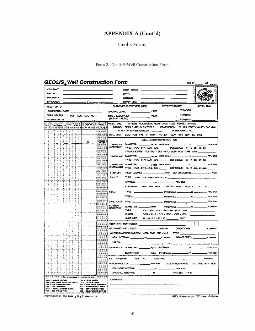
10
APPENDIX A (Cont’d)
Geolis Forms
Form 2. Geolis® Well Construction Form
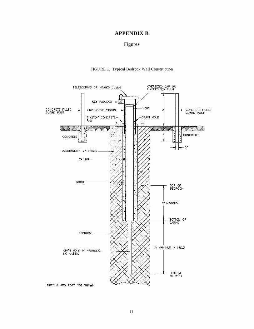
11
APPENDIX B
Figures
FIGURE 1. Typical Bedrock Well Construction
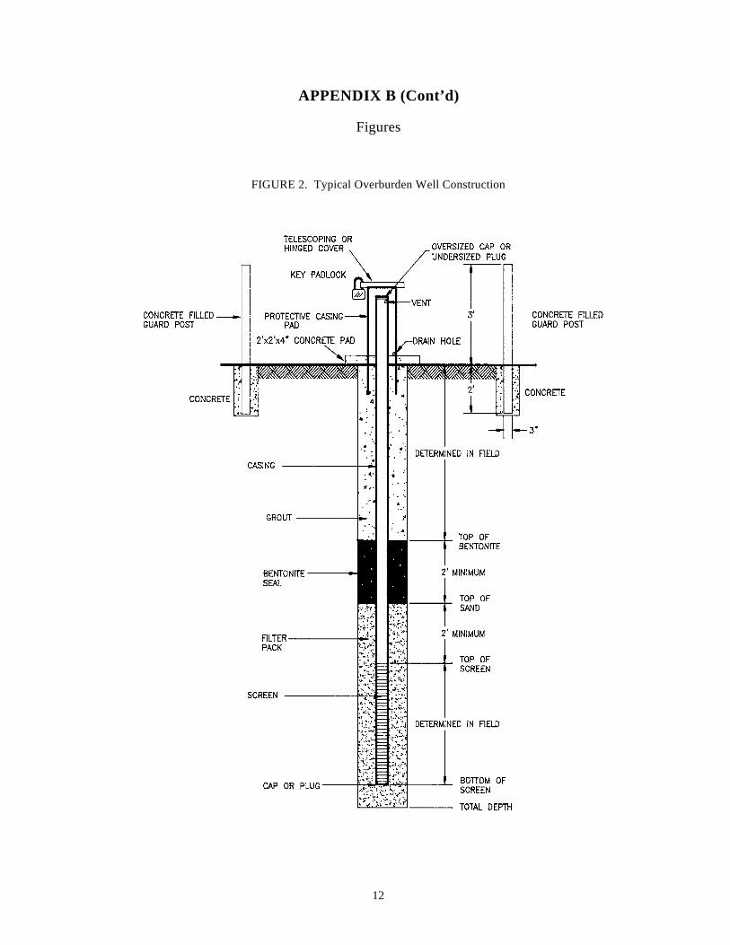
12
APPENDIX B (Cont’d)
Figures
FIGURE 2. Typical Overburden Well Construction

Appendix C

OSWER 9240.0-44 EPA 540-R-07-06
FINAL July 2007
Office of Superfund Remediation and Technology Innovation
Sampler’s Guide
Contract Laboratory Program Guidance for Field Samplers
Disclaimer: The final version of the document replaces any prior versions of the document in their entirety.

Foreword The intent of the Contract Laboratory Program (CLP) Guidance for Field Samplers is to replace the CLP Samplers Guide. This guidance document is designed to provide users with general information regarding environmental sample collection for the United States Environmental Protection Agency’s (USEPA) Contract Laboratory Program (CLP). This document provides minimum CLP requirements, an explanation of the general sampling process sequence of events, and any related information. The appendices contain useful reference information and checklists to aid in planning and documenting sampling activities.
CLP users also are encouraged to review the Introduction to the Contract Laboratory Program document that contains a general overview of the CLP, how it works, and how to access the program. The CLP requires samplers to use the functionality provided by the Field Operations Records Management System (FORMS) II Lite™ software, which is the preferred means of creating CLP sample documentation. For guidance in using the software to record and submit sampling data, users should reference the FORMS II Lite User’s Guide.
Both the Introduction to the Contract Laboratory Program and the Contract Laboratory Program Guidance for Field Samplers can be downloaded from the CLP Web site at the following address:
http://www.epa.gov/superfund/programs/clp/guidance.htm
The FORMS II Lite User’s Guide can be downloaded from the CLP Web site at the following address:
http://dyncsdao1.fedcsc.com/itg/forms2lite/doc.html
For more information regarding the CLP or this guide, please contact Elizabeth Holman via email at [email protected] or via telephone at (703) 603-8761.
Key Information
Text in blue and underlined indicates an external link to information outside of this document. The images below are located throughout the document to draw attention to important information and each are labeled accordingly:
Important
Note
ii
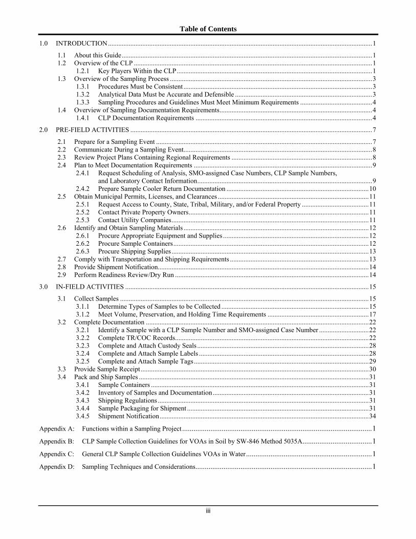
Table of Contents
1.0 INTRODUCTION..........................................................................................................................................................1
1.1 About this Guide..................................................................................................................................................1 1.2 Overview of the CLP ...........................................................................................................................................1
1.2.1 Key Players Within the CLP..................................................................................................................1 1.3 Overview of the Sampling Process ......................................................................................................................3
1.3.1 Procedure s Must be Consistent ..............................................................................................................3 1.3.2 Analytical Data Must be Accurate and Defensible ................................................................................3 1.3.3 Sampling Procedures and Guidelines Must Meet Minimum Requirements ..........................................4
1.4 Overview of Sampling Documentation Requirements.........................................................................................4 1.4.1 CLP Documentation Requirements .......................................................................................................4
2.0 PRE-FIELD ACTIVITIES .............................................................................................................................................7
2.1 Prepare for a Sampling Event ..............................................................................................................................7 2.2 Communicate During a Sampling Event..............................................................................................................8 2.3 Review Project Plans Containing Regional Requirements ..................................................................................8 2.4 Plan to Meet Documentation Requirements ........................................................................................................9
2.4.1 Request Scheduling of Analysis, SMO-assigned Case Numbers, CLP Sample Numbers, and Laboratory Contact Information......................................................................................................9
2.4.2 Pre pare Sample Cooler Return Documentation ...................................................................................10 2.5 Obtain Municipal Permits, Licenses, and Clearances ........................................................................................11
2.5.1 Request Access to County, State, Tribal, Military, and/or Federal Property .......................................11 2.5.2 Contact Private Property Owners.........................................................................................................11 2.5.3 Contact Utility Companies...................................................................................................................11
2.6 Identify and Obtain Sampling Materials ............................................................................................................12 2.6.1 Procure Appropriate Equipment and Supplies .....................................................................................12 2.6.2 Procure Sample Containers..................................................................................................................12 2.6.3 Procure Shipping Supplies ...................................................................................................................13
2.7 Comply with Transportation and Shipping Requirements .................................................................................13 2.8 Provide Shipment Notification...........................................................................................................................14 2.9 Perform Readiness Review/Dry Run .................................................................................................................14
3.0 IN-FIELD ACTIVITIES ..............................................................................................................................................15
3.1 Collect Samples .................................................................................................................................................15 3.1.1 Determine Types of Samples to be Collected ......................................................................................15 3.1.2 Meet Volume, Preservation, and Holding Time Requirements ...........................................................17
3.2 Complete Documentation ..................................................................................................................................22 3.2.1 Identify a Sample with a CLP Sample Number and SMO-assigned Case Number .............................22 3.2.2 Com plete TR/COC Records.................................................................................................................22 3.2.3 Complete and Attach Custody Seals ....................................................................................................28 3.2.4 Complete and Attach Sample Labels ...................................................................................................28 3.2.5 Complete and Attach Sample Tags......................................................................................................29
3.3 Provide Sample Receipt .....................................................................................................................................30 3.4 Pack and Ship Samples ......................................................................................................................................31
3.4.1 Sam ple Containers ...............................................................................................................................31 3.4.2 Inventory of Samples and Documentation...........................................................................................31 3.4.3 Shipping Regulations ...........................................................................................................................31 3.4.4 Sample Packaging for Shipment ..........................................................................................................31 3.4.5 Shipm ent Notification..........................................................................................................................34
Appendix A: Functions within a Sampling Project .....................................................................................................1
Appendix B: CLP Sample Collection Guidelines for VOAs in Soil by SW-846 Method 5035A.....................................1
Appendix C: General CLP Sample Collection Guidelines VOAs in Water...................................................................1
Appendix D: Sampling Techniques and Considerations..............................................................................................1
iii

Table of Contents (Cont.)
Appendix E: Sampling Checklists ............................................................................................................................1 Appendix E-1: Personnel Preparation Checklist .....................................................................................1 Appendix E-2: General Sample Collection Checklist..............................................................................2 Appendix E-3: Completing Field Logbook Checklist .............................................................................3 Appendix E-4: Completing Handwritten Sample Labels Checklist ..........................................................4 Appendix E-5: Completing Handwritten Sample Tags & Custody Seals Checklists ..................................5 Appendix E-6: Packing Sample Container Checklist ..............................................................................6 Appendix E-7: Packing Shipping Container Checklist ............................................................................7 Appendix E-8: Shipping & Reporting CLP Samples Checklist ................................................................8
Appendix F: Glossary .............................................................................................................................................1
List of Figures
Figure 3-1. Packaged Sample with Identification and Chain-of-Custody Documentation (Excluding TR/COC Record) ............................................................................................................................................................22
Figure 3-2. Organic Traffic Report & Chain of Custody Record (Laboratory Copy) ........................................................24 Figure 3-3. Inorganic Traffic Report & Chain of Custody Record (Laboratory Copy)......................................................25 Figure 3-4. Organic Traffic Report & Chain of Custody Record (Region Copy) ..............................................................26 Figure 3-5. Inorganic Traffic Report & Chain of Custody Record (Region Copy)............................................................27 Figure 3-6. Custody Seal ....................................................................................................................................................28 Figure 3-7. Completed Sample Tag ...................................................................................................................................30 Figure 3-8. Sample Receipt Created Using the FORMS II Lite Software..........................................................................30 Figure 3-9. Sample Cooler with Attached TR/COC Record and Cooler Return Documentation ......................................33 Figure 3-10. Sample Weight Log .........................................................................................................................................33 Figure 3-11. Shipping Cooler with Custody Seals ...............................................................................................................34
List of Tables
Table 1-1. Participants in the CLP Sampling Process ............................................................................................................2 Table 2-1. CLP Sample Number Letter Codes.....................................................................................................................10 Table 2-2. Container Type Specifications ............................................................................................................................13 Table 3-1. QC Sample Types and CLP Submission Requirements......................................................................................16 Table 3-2. Sample Collection Requirements for CLP SOW SOM01 (VOAs).....................................................................19 Table 3-3. Sample Collection Requirements for CLP SOW SOM01 (SVOAs, Pesticides and Aroclors) ...........................20 Table 3-4. Sample Collection Requirements for CLP SOW ILM05....................................................................................21 Table 3-5. Completing and Attaching a Custody Seal .........................................................................................................28 Table 3-6. Completing and Attaching a Handwritten Sample Tag ......................................................................................29 Table 3-7. Packing Samples for Shipment ...........................................................................................................................32 Table D-1. Mixing a Sample and Filling Sample Containers .............................................................................................D-2
iv
List of Acronyms
ASB Analytical Services Branch CERCLA Comprehensive Environmental Response, Compensation, and Liability Act CLP Contract Laboratory Program CLP PO CLP Project Officer CRQL Contract Required Quantitation Limit CVAA Cold Vapor Atomic Absorption DOT Department of Transportation DQO Data Quality Objective dbf Database File ET Eastern Time FORMS II Lite™ Field Operations Records Management System II Lite FSP Field Sampling Plan HCN Hydrocyanic acid IATA International Air Transport Association ICP-AES Inductively Coupled Plasma-Atomic Emission Spectroscopy ICP-MS Inductively Coupled Plasma-Mass Spectrometry MS Matrix Spike MSD Matrix Spike Duplicate NAHSO4 Sodium Bisulfate NPL National Priorities List OSC On-scene/on-site Coordinator OSHA Occupational Safety and Health Administration OSRTI Office of Superfund Remediation and Technology Innovation OSWER Office of Solid Waste and Emergency Response PCBs Polychlorinated Biphenyls PE Performance Evaluation PM Program Manager ppb Parts-Per-Billion ppt Parts-Per-Trillion PRP Potentially Responsible Party PT Proficiency Testing PTFE Polytetrafluoroethylene PVC Polyvinyl Chloride QA Quality Assurance QAPP Quality Assurance Project Plan QASPER Quality Assurance Sampling Plan for Environmental Response QATS Quality Assurance Technical Support QC Quality Control RAS Routine Analytical Services RPM Remedial Project Manager RSCC Regional Sample Control Center Coordinator RSM Regional Site Manager SAM Site Assessment Manager SAP Sampling Analysis Plan SARA Superfund Amendments and Reauthorization Act SDG Sample Delivery Group SMC System Monitoring Compound SMO Sample Management Office SOP Standard Operating Procedure SOW Statement of Work SVOA Semivolatile Organic Analyte TR/COC Traffic Report/Chain of Custody txt Text File UN United Nations USEPA United States Environmental Protection Agency VOA Volatile Organic Analyte XML eXtensible Markup Language
v

THIS PAGE INTENTIONALLY LEFT BLANK
vi
Chapter 1 – Introduction to this Guide
1.0 INTRODUCTION
1.1 About this Guide
This document describes the important organizational roles and responsibilities for those who plan and conduct environmental sample collection projects for analysis through the Superfund’s Contract Laboratory Program (CLP). This chapter introduces the structure and purpose of this document. Chapter 2, Pre-field Activities, addresses pre-field planning activities that the sampling team could complete prior to the actual sampling event. Chapter 3, In-field Activities, addresses those activities that need to be completed during the sampling event.
Appendix A describes the functions within a sampling project which are taken from the Quality Assurance Project Plan requirements. Appendix B and Appendix C contain the sample collection guidelines for Volatile Organic Analytes (VOAs) in soil and in water. Appendix D recommends sampling techniques. Appendix E contains checklists to help the sampler ensure that all necessary steps are completed.
A project and site-specific Quality Assurance Project Plan (QAPP) providing Regional guidance will override guidance given within this document.
1.2 Overview of the CLP
The CLP is a national program of commercial laboratories under contract to support the USEPA’s nationwide effort to clean up designated hazardous waste sites by supporting its Superfund program. The Superfund program was originally established under the Comprehensive Environmental Response, Compensation, and Liability Act (CERCLA) of 1980 and presently exists under the Superfund Amendments and Reauthorization Act (SARA) of 1986.
The CLP uses state-of-the-art technology to provide users with analytical services. The program provides data of known and documented quality to support USEPA enforcement activities or other user needs. To achieve this goal, the CLP has established strict Quality Control (QC) procedures and detailed documentation requirements. Current CLP users include the USEPA Regions, States and Tribal governments, and other Federal agencies. CLP users also are encouraged to review the Introduction to the Contract Laboratory Program document that contains a general overview of the CLP, how it works, and how to access the program.
1.2.1 Key Players Within the CLP
In coordinating Superfund sampling efforts, the Analytical Services Branch (ASB) is supported by the Sample Management Office (SMO) contractor, the Regional CLP Project Officers (CLP POs), the Regional Sample Control Center Coordinators (RSCCs), and the Regional Site Managers (RSMs), including Site Assessment Managers (SAMs), On-scene/On-site Coordinators (OSCs), and Remedial Project Managers (RPMs). Samplers may work directly with the RSCC and/or RSM (or equivalent), and/or an OSC from the Field Support Section during a sampling event. See Table 1-1 for a brief description of the functions performed by key participants (functions may vary by Region).
FINAL July 2007 1

Chapter 1 – Introduction to this Guide
Table 1-1. Participants in the CLP Sampling Process
Participants Responsibilities
Analytical Services Branch USEPA ASB directs the CLP from within the Office of Superfund Remediation and Technology Innovation (OSRTI) in the Office of Solid Waste and Emergency Response (OSWER). ASB responsibilities include: • Development of the Statements of Work (SOWs) that define required analytical methods
(including QC, detection/quantitation limits, and holding times) for the analytical services procured under the CLP;
• Development and implementation of policies and budgets for Superfund analytical operations;
• Development of information management policies and products for analytical data; • Management of SMO and Quality Assurance Technical Support (QATS) contracts; • National administration, evaluation, and management of the CLP; and • Direction of CLP Quality Assurance (QA) activities in coordination with overall OSWER
QA activities. To obtain the most current ASB contact list, refer to the following Web site:
http://www.epa.gov/superfund/programs/clp/contacts.htm#ASB
CLP Sample Management Office The contractor-operated SMO provides necessary management, operations, and administrative support to the CLP. SMO receives Regional analytical requests, coordinates and schedules sample analyses, and tracks sample shipments. SMO also receives and checks data for completeness and compliance, processes laboratory invoices, and maintains a repository of sampling records and program data.
CLP Contract Laboratories The contractor-operated laboratories within CLP provide necessary analytical services for the isolation, detection, and quantitation of the CLP's target compounds and analytes.
Regional CLP Project Officer The CLP PO monitors the technical performance of the contract laboratories in each Region. The CLP PO works closely with ASB Program Managers (PMs) to identify and resolve laboratory technical issues, and leads laboratory on-site evaluations. To obtain the most current CLP PO contact list, refer to the following Web site:
http://www.epa.gov/superfund/programs/clp/polist.htm
Regional Sample Control Center Coordinator
In most Regions, the RSCC coordinates sampling efforts and serves as the central point-of-contact for sampling questions and problems. The RSCC works with SMO to schedule sample shipments to laboratories. In addition, the RSCC’s activities may include: informing SMO of sample shipment, cancellations, special instructions, and sampling issues. To obtain the most current RSCC contact list, refer to the following Web site:
http://www.epa.gov/superfund/programs/clp/rscclist.htm
Regional Site Manager The RSM Coordinates the development of acceptance or performance criteria and oversees project-specific contractors, state officials, or private parties conducting site sampling efforts. The RSM could be the SAM, the OSC, or the Remedial Project Manager (RPM).
Field Support Section The Field Support Section consists of personnel such as the OSC, SAM, and RPM. In most Regions, the Field Support Section develops Standard Operating Procedures (SOPs) for field sampling and related procedures, and assists sampling teams in following those SOPs. The sampling team determines what type(s) of CLP services will be required for a particular sampling event. The Field Support Section reviews Sampling Analysis Plans (SAPs) prepared by sampling teams and oversees sampling teams in the field. The Field Support Section may also prepare their own SAPs, perform sampling activities in the field, and analyze and report the results of their sampling events to the RSM.
FINAL July 2007 2

Chapter 1 – Introduction to this Guide
1.3 Overview of the Sampling Process
Once USEPA has determined that physical, chemical, and/or biological testing of a site is necessary, samples of material from the
At–a-Glance:site area must be collected. The type of material that must be Overview of the Sampling Process collected and the analytical method to be used depends upon the physical location of the site, detection level(s), site history (previous 3 Procedures must be consistent. sampling), and known or unknown conditions and contaminants. 3 Analytical data must be accurate and The sampling process includes carefully planned and consistently defensible. applied procedures that produce accurate and legally defensible data. 3 Procedures must meet minimum The sampling team should consider the procedures and plans requirements. presented in this guide as minimum sampling process guidelines to maintain sample integrity and identity. Samples should be collected according to the approved project and site-specific QAPP and SAP. This document does not define specific sampling procedures because specific sampling protocols depend on individual site conditions, Regional requirements, and acceptance and performance criteria. Since Regions may have their own specific requirements for individual sampling programs, they are responsible for generating Region-specific sampling SOPs.
1.3.1 Procedures Must be Consistent
The purpose of sampling is to collect representative portions from a suspected contaminated site. Sample collection is critical to determining the presence, type, concentration, and extent of environmental contamination by hazardous substances, thus it is a crucial part of every sampling and environmental testing effort. Sampling procedures must be consistently written and followed to mitigate risk of error and the expense of re-sampling.
Failure to follow proper sampling and shipping procedures could result in samples that are contaminated, broken, mislabeled, lost during shipping, or unusable because of a missed holding time. If procedures are inconsistently or improperly followed, any resultant analytical data may be inaccurate and may not be defensible in a court of law.
If re-sampling is needed due to improper sampling, the sampling team may incur the cost.
1.3.2 Analytical Data Must be Accurate and Defensible
The data gathered during sampling activities helps to accurately characterize contaminated waste sites so that the impact on human health and the environment can be properly evaluated. Acquiring accurate and defensible data that will be accepted in a court of law is the CLP’s primary objective; therefore, the sampler must collect samples according to strict sampling procedures, plans, and guidelines. USEPA and many other Federal agencies use data resulting from analytical testing of soil/sediment/aqueous samples to:
• Determine if a site is contaminated with organic and/or inorganic compounds; • Identify pollution sources and Potentially Responsible Parties (PRPs); • Validate remedial design methodologies; • Assess response and remedial priorities; • Assess risk to human health and the environment; • Determine appropriate cleanup actions; and • Determine cleanup achievements.
FINAL July 2007 3

Chapter 1 – Introduction to this Guide
1.3.3 Sampling Procedures and Guidelines Must Meet Minimum Requirements
It is imperative that samplers be aware of the minimum CLP and Regional requirements that directly impact and define how a sampling event will take place. It is important to note that the procedures and guidelines set forth in this document are considered minimum CLP requirements. Samplers should reference the following sections within this document that specifically address important requirements that must be met for a successful sampling event:
• Section 1.4.1 CLP Documentation Requirements; • Section 2.4.1 Request Scheduling of Analysis, SMO-assigned Case Numbers, CLP Sample Numbers,
and Laboratory Contact Information; • Section 2.7 Comply with Transportation and Shipping Requirements; • Section 2.8 Provide Shipment Notification; • Section 3.1 Collect Samples; and • Section 3.2 Complete Documentation.
1.4 Overview of Sampling Documentation Requirements
The sampler must properly document samples collected for analysis in order to uniquely identify each sample and ensure At–a-Glance:adequate chain-of-custody procedures. When collecting Overview of the Sampling Document samples, the sampler should always keep in mind that any Requirements samples collected may be used in future litigation. This is especially important when samples are from privately owned 3 Must use FORMS II Lite to create sample
property. If sampling on privately owned property, samplers documentation. Analytical data must be accurate and defensible. should also provide the property owner with a receipt for
samples collected and removed from that owner’s property. 3 CLP documentation requirements:
Samplers may also be required by a Region to use a sample - CLP Sample Number label, sample tag, or field operations records documenting - SMO-assigned Case Number information such as daily activities, equipment and materials - Traffic Report/Chain of Custody used, personnel involved, site security, etc. These types of (TR/COC) Record documentation help ensure proper sample identification and - Sample Labels provide additional chain-of-custody records. - Sample Tags
The documentation required by a Region for a sampling event is - Custody Seals
outlined in project plans such as the QAPP, SAP, and Field - Field Operation Records
Sampling Plan (FSP).
Under no circumstances should the site name appear on any documentation that is sent to the laboratory (for the CLP).
1.4.1 CLP Documentation Requirements
Samplers must:
1) Record the CLP Sample Number on each sample bottle; 2) Complete the Traffic Report/Chain of Custody (TR/COC) Record using the FORMS II Lite software,
making sure to indicate on the TR/COC Record if the samples require the use of a Modified Analysis;
3) Complete and attach sample labels; 4) Complete and attach sample tags to meet Regional requirements; 5) Complete and attach custody seals to meet Regional requirements; and 6) Complete field operations records, as necessary.
Please contact your RSCC (see Table 1-1) for information regarding CLP Sample Numbers, SMO- assigned Case Numbers, TR/COC Records, and chain-of-custody seals for sampling events.
FINAL July 2007 4
Chapter 1 – Introduction to this Guide
For information regarding using FORMS II Lite to create and complete a TR/COC Record, refer to the following Web site:
http://www.epa.gov/superfund/programs/clp/f2lite.htm
1.4.1.1 CLP Sample Number A CLP Sample Number is unique per sampling location and is used to identify and track samples throughout the sampling and analytical processes and is recorded on many types of sampling documentation (e.g., TR/COC Records, sample labels, and sample tags). CLP Sample Numbers are provided to samplers by their RSCC or SMO.
Samplers must contact their RSCC (or their designee) to obtain CLP Sample Numbers for their sampling event. Samplers must correctly assign the CLP Sample Numbers to the appropriate sample bottle or container. Please refer to Section 3.2.1 for more detailed information regarding the use of CLP Sample Numbers.
If the sampler has any questions regarding the assignment of CLP Sample Numbers, they should contact their RSCC.
1.4.1.2 SMO-assigned Case Number SMO-assigned Case Numbers are used to track groups of samples throughout the sampling and analytical processes and are recorded on many types of sampling documentation (e.g., TR/COC Records, sample labels, and sample tags). Samplers must correctly assign the SMO-assigned Case Number to the appropriate sample bottle or container. To obtain a SMO-assigned Case Number, samplers must contact their RSCC (or their designee).
1.4.1.3 Laboratory Assignment Samplers are responsible for shipping samples to the appropriate SMO-assigned laboratory for analysis. Samplers must contact their RSCC (or their designee) to obtain their laboratory assignment or they may be provided by SMO.
1.4.1.4 TR/COC Record The TR/COC Record is used as physical evidence of sample custody and functions as a permanent record of each sample collected.
Per CLP documentation requirements, each cooler must contain a TR/COC Record that lists all the samples contained therein.
In an effort to automate sample documentation in the field, ASB has developed a stand-alone, Windows-based software application that samplers can use to automatically create and generate sample documentation. The FORMS II Lite software allows users to enter information prior to and during sampling events. It allows users to multi-task and electronically create, edit, and print documentation associated with sampling activities. Users can customize data entry screens throughout the entire documentation process. Users can also customize the format and content of sample labels based on specific requirements.
The program simplifies and accelerates the tedious manual sample documentation process by reducing the generation of handwritten documents by almost 70%. The FORMS II Lite software enables samplers to:
• Increment CLP Sample Numbers or manually assign their own unique, project-specific non-CLP Sample Numbers;
• Input the SMO-assigned Case Number into the appropriate field; • Create sample labels, sample tags, TR/COC Records, Sample Weight forms, and receipts
for samples taken from a site; • Track samples from the field to the laboratory;
FINAL July 2007 5
Chapter 1 – Introduction to this Guide
• Electronically capture sample information into databases; and • Export electronic data as a database File (.dbf), Text (.txt), or eXtensible Markup
Language (.xml) file.
USEPA requires samplers to use the FORMS II Lite software for all CLP sampling efforts. For assistance with obtaining or using the FORMS II Lite software, please contact the FORMS II Lite Help Desk at 703-818-4200 from 9:00 AM - 5:00 PM Eastern Time (ET). For additional information regarding FORMS II Lite use and training, please refer to the following Web site:
http://www.epa.gov/superfund/programs/clp/f2lite.htm
1.4.1.5 Chain-of-Custody Seals A chain-of-custody seal is any adhesive label or tape that can be used to seal a sample bottle, container, plastic bag, or shipping cooler such that if it is opened or tampered with, the seal will be broken. Custody seals must be placed on each sample bottle, container, or bag (as appropriate) and each shipping cooler or container. The custody seal is an excellent means of maintaining a record of chain-of-custody, as well as guarding against possible sample contamination or tampering during shipping.
1.4.1.6 Sample Labels A sample label is a sticker attached to a sample bottle or container that contains a sample. Sample labels are affixed to each sample container as samples are collected in the field or affixed prior to going in the field. A sample label must contain, at a minimum, a CLP Sample Number so that they can be associated with, and listed on, the associated TR/COC Record. The sample label may also include the required analysis/fraction and preservative used (to eliminate confusion at the laboratory). Samplers should refer to their project plans for Region-specific sample label requirements.
1.4.1.7 Sample Tags A sample tag identifies a sample bottle or container that contains a sample. The tag also provides specific analytical direction and proof that a sample existed. To support the use of sample data in potential enforcement actions, samples with other than in situ measurements (e.g., pH, temperature, conductivity) can be identified with a sample tag. A CLP Sample Number and SMO-assigned Case Number must be recorded on a sample tag to indicate that the sample container comprises the whole sample in the case where there is just one container of sample, or part of the indicated sample in the case of multiple containers of sample. Samplers should refer to their project plans for Region-specific sample tag requirements.
1.4.1.8 Field Operation Records Samplers should maintain complete, accurate, and legible field operations records as they perform a sampling activity. The following records are included: Field Logbooks; Corrective Action Reports; Sampling Trip Reports; supplemental standardized forms; logs; and records such as maps or photographs that document each step of the work performed in the field. Samplers should refer to their project plans for Region-specific field operations record requirements. These records are very important tools because they are considered part of the official project file when legal issues arise.
1.4.1.9 Weight Logs A sample weight log identifies the tared, sample and final weights per bottle for VOA samples. In order to support Method 5035 for VOAs, samplers should enter tared and final weights per bottle in the CLP Sample Weight Log.
FINAL July 2007 6

Chapter 2 – Pre-field Activities
2.0 PRE-FIELD ACTIVITIES
This chapter provides instructions for completing the suggested pre- field activities that samplers could complete prior to performing At-a-Glance:
Pre-field Activities sampling activities. These important pre-field activities will save time and help the sampler to better prepare for the sampling event. 3 Prepare for and communicate during a
Samplers should be aware of issues routinely arise during the sampling event. sampling process so that samplers can avoid making the same 3 Review project plans containing Regional mistakes or having the same problems that could adversely affect requirements. their sampling event. Samplers are also expected to review all 3 Plan to meet documentation requirements. pertinent project plans and meet both CLP and Regional 3 Obtain any necessary permits, licenses, requirements that directly impact the structure and purpose of a and clearances. sampling event. 3 Identify and obtain sampling materials.
3 Comply with transportation and shipping The project plans provide information such as the types and numbers requirements. of samples to be collected, the analytical methods to be used based 3 Provide shipment notification.on the desired level of quantitation, and the necessary equipment and
3 Perform Readiness Review/Run-through.supplies. The plans also describe the sampling method which may require different specific sample volumes/masses, containers, preservation, shipping, and handling to maintain the integrity of the samples without degradation or contamination.
In addition to reviewing project plans, samplers should determine if the sampling site is privately or publicly owned and obtain the necessary permission to access the sampling site. If the site is privately owned, samplers should make sure to have receipts for available samples to provide to the owner for all samples collected and removed from their property. Samplers must also prepare to identify and obtain sampling materials, prepare to meet documentation requirements by obtaining and learning to use the required software, comply with transportation and shipping requirements, and perform a readiness review/dry run of the sampling process.
2.1 Prepare for a Sampling Event
Samplers must prepare to meet CLP and Regional requirements for a sampling event, appropriately use the CLP Sample Number and SMO-assigned Case Number, complete the TR/COC Record using the FORMS II Lite software, and complete and attach the custody seal(s). It is very important that the sampler include the correct CLP Sample Number on each sample. It is also imperative that the TR/COC Record be accurately completed and submitted with the sample(s). Finally, the sampler must accurately and legibly complete and attach a custody seal to each sample container, or plastic sample bag (as appropriate), and each shipping cooler or container.
However, meeting the sampling requirements requires more than just the proper application of a CLP Sample Number on each sample, completion of the TR/COC Record, and use of a custody seal. The actual collection of samples, packaging, and shipping of those samples are equally important to a successful sampling event.
For example, if a sampler collects an insufficient volume of a sample, the laboratory may not be able to perform the requested analysis. Insufficient sample volumes may also result in a laboratory being unable to perform laboratory quality control, such as Matrix Spike (MS), Matrix Spike Duplicate (MSD), and Duplicate sample analysis. Additionally, if the laboratory receives a sample that is either unpreserved or the sample pH is outside of the required range, the sample cannot be properly analyzed.
Unfortunately, improper shipping and labeling processes and procedures often result in:
• Samples being shipped to the wrong laboratory; • Broken or empty samples being received at the laboratory; and • Custody seals or sealant tape that is missing or broken on sample bottles, containers, plastic bags, or shipping
coolers shipped to the laboratories.
The importance of completing the paperwork associated with a sampling event cannot be overemphasized. Samplers must make a conscientious effort to accurately complete the TR/COC Record since this is the main document used to derive vital information about a particular sample. The person completing a TR/COC Record
FINAL July 2007 7

Chapter 2 – Pre-field Activities
must be careful to avoid errors such as the appropriate sample(s) not being listed, or the wrong samples being listed. In an effort to eliminate such errors and the confusion that can be associated with handwritten TR/COC Records, samplers must use the FORMS II Lite software to complete the TR/COC Record and other associated sampling documentation.
It is extremely important that QC samples, including field sample duplicates, field samples for Matrix Spike and Matrix Spike Duplicate analyses, and Proficiency Testing (PT) samples, also known as Performance Evaluation (PE) samples, be designated and labeled per Regional guidance by samplers in the field. Mislabeling of QC samples can result in improper and/or inaccurate analysis of a sample at the laboratory.
2.2 Communicate During a Sampling Event
Communication is a key element in planning, administrating, and conducting a sampling event. It is extremely important that all parties involved in a sampling event be in contact throughout the sampling process. The procedures and recommendations outlined in this guide are based on more than 20 years of experience. It has been demonstrated that approximately 50% of all sampling efforts have been negatively affected by incorrect sampling procedures and poor communication among participants.
The key elements of communication for a sampling event include the relationship between the RSCC, SMO, the samplers in the field, and the laboratories who will be accepting the samples. For instance, the samplers must contact the RSCC to start the process for setting up a sampling event. The RSCC will in turn contact SMO who will schedule the sampling event, establish laboratory availability, and arrange for the laboratory to accept projected samples. SMO will then communicate the laboratory assignment to the Region and possibly the sampler.
The sampler should contact the RSCC (per Regional guidelines) and allow enough time for the RSCC to contact SMO at least a week prior to the sampling event.
SMO provides SMO-assigned Case and CLP Sample Numbers in time for the sampling event. SMO also schedules a laboratory and makes sure the laboratory will not have any capacity problems. Communication is also important because if there is a change in the sampling event due to a cancellation or an increase or decrease in the number of samples that will be sent to the laboratory, the sampler can contact the RSCC who can work with SMO to remedy potential capacity, availability, or overbooking problems.
2.3 Review Project Plans Containing Regional Requirements
In addition to meeting CLP requirements, the sample collection process must fulfill numerous Regional requirements. These requirements are determined by a variety of factors that affect how samples should be collected for an individual sampling event. These factors include:
• The type of samples being collected (organic/inorganic, water, soil/sediment, etc.); • The method by which the samples will be analyzed; • The acceptance or performance criteria (i.e., Data Quality Objectives [DQOs]); and • The type of data needed.
The QAPP for each sampling project is written to meet requirements outlined in the documents EPA Requirements for Quality Assurance Project Plans (QA/R-5), EPA Guidance on Quality Assurance Project Plans (G-5), and Regional QAPP preparation documents. The QAPP is prepared in advance of field activities and is used by samplers to develop any subsequent plans such as the Sampling SAP or the FSP. Samplers should review the QAPP and any subsequent project plans for information outlining the basic components of a sampling activity. QAPP and project plans should be finalized and approved by appropriate Regional QA personnel, the OSC, SAM, or the RPM before providing them to the sampling team. This should be done prior to the start of field activities. Appendix A explains the functions within a sampling project (as these functions relate to a sampling event) and the elements of that function as described in a typical QAPP. Copies of all project plans and relevant SOPs should be maintained in the field for the duration of the sampling project.
FINAL July 2007 8

Chapter 2 – Pre-field Activities
2.4 Plan to Meet Documentation Requirements
Sampling events require a variety of accurate and complete documentation. Samplers should review their project plans At-a-Glance: to determine the types of documentation that must be Plan to meet documentation requirements. completed for a sampling project and to ensure that the appropriate documentation will be on-hand in the field. The 3 Request SMO-assigned Case and CLP Sample
CLP documentation requirements include the CLP Sample Numbers.
Number, the SMO-assigned Case Number, the TR/COC 3 Prepare sample cooler return documentation.
Record, sample labels, sample tags, custody seals, and field 3 Prepare to use the FORMS II Lite software. operations records (as necessary). Samplers need to request SMO-assigned Case and CLP Sample Numbers for each sampling event prior to starting field activities. Samplers also need to make sure that the correct TR/COC Records (Organic TR/COC Record for organic analysis or Inorganic TR/COC Record for inorganic analysis) are being used within the FORMS II Lite software. Finally, samplers should be prepared to complete the appropriate shipping cooler return documentation.
Since samplers are required to use the FORMS II Lite software to prepare and submit sampling project documentation and maintain sample chain-of-custody, software users must be familiar with all emergency back up procedures that should be followed in the event of a system failure. Samplers must have access to FORMS II Lite-generated TR/COC Records at sampling events. If problems are experienced while using the FORMS II Lite software, please contact the FORMS II Lite Help Desk at 703-818-4200 from 9:00 AM - 5:00 PM ET.
In the event of a system crash, samplers must have backup hardcopies of FORMS II Lite TR/COC Records. For information regarding emergency backup procedures, please refer to the following Web site:
http://www.epa.gov/superfund/programs/clp/trcoc.htm
2.4.1 Request Scheduling of Analysis, SMO-assigned Case Numbers, CLP Sample Numbers, and Laboratory Contact Information
SMO-assigned Case Numbers are assigned based on a request for CLP Routine Analytical Services (RAS), which is processed though the RSCC (or his/her designee). The sampler must request the RSCC to schedule CLP RAS analysis. The CLP does have the capacity to schedule sampling on an emergency basis, however the sampler must contact the RSCC (or his/her designee) to obtain details regarding how to handle such a situation. When scheduling a sampling event that will last for more than one week, it is recommended that the sampler contact the RSCC (or his/her designee) on a weekly basis to provide updates. This contact between the sampler, the RSCC (or his/her designee), and SMO is very important because it will ensure better availability of laboratory capacity.
In addition to SMO-assigned Case and CLP Sample Numbers, samplers should make sure to have accurate laboratory contact information, such as:
• Laboratory name; • Laboratory address; • Contact name; and • Laboratory phone number.
This information is used for both TR/COC Records and chain-of-custody documentation and shipping paperwork such as address labels and airbills.
The SMO-assigned Case Number is used to track groups of samples throughout the sampling and analytical processes. Samplers must correctly indicate the assigned Case Number on the appropriate sample bottle or container.
The RSCC (or his/her designee) provides the CLP Case Numbers and Sample Numbers for each sampling event to samplers. Once the CLP Sample Numbers have been provided to the sampler, the sampler can use FORMS II Lite to print them onto sample labels.
The following characters are not to be used in generating CLP Sample Numbers and should never appear on any paperwork submitted to the laboratory: I, O, U, and V.
FINAL July 2007 9
Chapter 2 – Pre-field Activities
A CLP Sample Number is defined as a number that is unique per sampling location and identifies each CLP sample (see Section 1.4.1.1). Since samples must be identified per analytical program (either organic or inorganic), there are two types of TR/COC Records and two letter codes to denote organic vs. inorganic analysis.
A CLP sample is defined as one discrete portion of material to be analyzed that is contained at one concentration level, from one station location for each individual or set of analytical fractions -- provided the fractions are all requested for the same CLP analytical service (i.e., organic or inorganic), and identified by a unique Sample Number.
When samples are collected from several station locations to form a composite sample, the composite sample should be assigned either a number from one of the station locations used during collection, or a unique number that represents the composite sample for tracking purposes. The numbering scheme used internally at a sampling event for identifying composite samples should also be documented appropriately (e.g., in the field logs).
Organic CLP Sample Numbers begin with the Regional letter code, followed by four letters and/or numbers. Inorganic CLP Sample Numbers begin with “M”, followed by the Regional letter code and then four letters and/or numbers. See Table 2-1 for Region and letter codes for each sample type (i.e., organic or inorganic).
Table 2-1. CLP Sample Number Letter Codes
Region Letter Code Organic Inorganic
1 A MA 2 B MB 3 C MC 4 D MD 5 E ME 6 F MF 7 G MG 8 H MH 9 Y MY
10 J MJ
According to CLP guidelines, each individual inorganic water sample may be analyzed for total metals or dissolved metals, but not both. Therefore, water samples collected for total metal and dissolved metal analyses from the same sampling location must be assigned separate (unique) CLP Sample Numbers. A sampler can use the same CLP Sample Number for an inorganic soil or water sample collected for total metals, mercury and cyanide analyses.
Organic soil and water samples may be collected for analysis under the SOM01 SOW to detect:
• Aroclors; • Semivolatile Organic Analytes (SVOAs); • Pesticides; • Volatile Organic Analytes (VOAs); and/or • Trace Volatile Analytes
Inorganic soil and water samples may be collected for analysis for cyanide, and for metals using Inductively Coupled Plasma-Atomic Emission Spectroscopy (ICP-AES) and Cold Vapor Atomic Absorption (CVAA), under the ILM05.X SOW.
Inorganic water only samples may be collected for analysis for cyanide, and for metals using Inductively Coupled Plasma-Mass Spectrometry (ICP-MS) and CVAA, under the ILM05 SOW.
2.4.2 Prepare Sample Cooler Return Documentation
CLP laboratories must routinely return sample shipping coolers to the appropriate sampling office within 14 calendar days following receipt of shipment from the sampler. For sample coolers to be returned, the
FINAL July 2007 10

Chapter 2 – Pre-field Activities
sampler must complete the appropriate cooler documentation and work with Regions and government agencies to provide a cost-effective mechanism for laboratories to return the empty coolers to the appropriate sampling office. The sampling cooler return documentation can be prepared in advance and provided to samplers before field activities begin. The sampler (not the CLP laboratory) is responsible for paying for return of the cooler and should also include shipping airbills bearing the sampler’s account number, as well as a return address to allow for cooler return.
To maintain consistency among cooler transportation programs, samplers should:
• Minimize the use of multiple transportation carriers to avoid confusion; • Use multiple-copy labels so the laboratory and the sampling team can each retain a copy for their
records; • Prepare labels in advance so that the laboratory can simply affix a completed shipping label on the
cooler; • Include third-party billing information (i.e., their shipping account number) on labels so the
laboratory will not be billed by the transportation carrier; • Confirm that the laboratory knows which transportation carrier to use; and • Include the SMO-assigned Case Number on return information.
2.5 Obtain Municipal Permits, Licenses, and Clearances At-a-Glance:
Obtain permits, licenses, and clearances.
Before starting a sampling event, samplers must make sure to 3 Request access to County, State, Tribal, obtain the proper municipal permits, accesses to the property, military, and/or Federal property. and any government clearances, if required. The sampler must 3 Contact private property owner(s). also contact any appropriate utility companies to ascertain where 3 Contact utility companies. any underground pipes, cables, etc., may be located.
2.5.1 Request Access to County, State, Tribal, Military, and/or Federal Property
Proper access to perform sampling activities is important not only for legal reasons, but also to eliminate delays in work and possible refusal to allow sampling to take place. It is crucial that the appropriate permits, licenses, and clearances be secured to obtain access for sampling activities that will be performed on County, State, Tribal, military, and/or Federal property. The sampler must contact the appropriate government offices or personnel well in advance to determine what kinds of approval are required. Pre-approval may be required for specific types of sample collection such as drilling or excavation. For example, drilling on a military base requires pre-approval. Base security may require clearances for all members of the sampling team, including subcontractors. This process may take two or more days.
If arrangements are not made in advance, the team may not be allowed to enter the site until their clearances are processed and the team has been approved to drill. As a result, the sampling schedule is delayed, costing extra time and money.
2.5.2 Contact Private Property Owners
The sampler must obtain written permission from the private property owner(s) before sampling on their property, even if verbal permission has been granted. It is recommended that samplers obtain verbal permission prior to their arrival at the sampling location, but written permission can be obtained on the day of sampling. If a property owner refuses to grant access to their property, it may be necessary for sampling participants to contact the appropriate authorities for assistance.
2.5.3 Contact Utility Companies
The sampler should contact local utility companies (e.g., power, phone, gas, cable, sanitation, etc.) at least one week prior to the sampling event to have underground cables, lines, and pipes flagged and marked. This is required by law. A national one-call directory can be found at:
http://www.digsafely.com/contacts.htm.
FINAL July 2007 11
Chapter 2 – Pre-field Activities
This will eliminate potential safety hazards and service disruption. For example, soil sampling in a residential area may require digging below the soil’s surface. It is very important to know where utility lines and pipes are located so that samplers do not hit live electrical wires or rupture gas lines. Samplers should follow Regional or other appropriate program procedures for the procurement of such services. The utility service(s) disruption dates should be confirmed at least two days prior to sampling activities.
Pre-payment of survey fees to local utility companies may be required.
2.6 Identify and Obtain Sampling Materials At-a-Glance: Identify and obtain sampling materials.
Samplers must make sure to be prepared for a sampling project 3 Procure appropriate equipment and with the appropriate sampling materials (equipment, supplies, supplies.sample containers, packing materials, and shipping materials). The
equipment and supplies must be properly cleaned, calibrated, and 3 Procure sample containers.
tested as necessary to meet the needs of the sampling project. 3 Procure shipping supplies.
2.6.1 Procure Appropriate Equipment and Supplies
Each sampling event requires the procurement of equipment and materials to collect, document, identify, pack, and ship samples. The proper field sampling equipment is vital to a successful sample collection. Regional or other samplers should obtain, and arrange in advance, all of the equipment and supplies required for each sampling event. Samplers should review the project plans to verify that the proper equipment is being used for sample collection.
At a minimum, the following materials are generally required during a sampling event:
• Sample storage containers; • Packing material; • Sample containers; • Shipping containers; • Access to the FORMS II Lite software for creating sample labels, stickers, tags, and TR/COC
Records; • Custody seals; and • Sampling equipment such as bowls, augers, pumps, etc.
Sampling events may also require specific items such as:
• Cooler temperature blanks; • Trip blanks for VOA analysis; • Preservation supplies (e.g., ice or acid); and • Specially prepared sample vials (e.g., for SW-846 Method 5035A).
2.6.2 Procure Sample Containers
The analytical protocol(s) to be used for sample analysis often requires the use of a particular type of sample container. The type of container also may depend on the sample matrix and analysis. It is recommended that samplers use borosilicate glass containers, which are inert to most materials, when sampling for pesticides and/or other organics. Conventional polyethylene is recommended when sampling for metals because of the lower cost and absorption rate of metal ions.
Using the wrong container may result in breakage, gathering of an insufficient volume needed to perform sample analysis, or the container material may interfere with the analysis. Therefore, samplers should identify and use the correct sample containers for each sampling event.
Containers procured for a sampling event are usually pre-cleaned and shipped ready-for-use from the manufacturer to the sampling site. Regardless of the type of container used, samplers must ensure that the containers have been analyzed or certified clean to levels below concern for the project. These containers must meet the USEPA container type specifications listed in Table 2-2.
FINAL July 2007 12
Chapter 2 – Pre-field Activities
Table 2-2. Container Type Specifications
Reference Number Container Type
Specifications
Closure Septum
1 40 mL amber glass vial, 24 mm neck finish.
Polypropylene or phenolic, open-top screw-cap, 15 cm opening, 24-400 size.
24 mm disc of 0.005 in. Polytetrafluoroethylene (PTFE) bonded to 0.120 in. silicone for total a thickness of 0.125 in.
2 1 L high density polyethylene, cylinder-round bottle, 28 mm neck finish.
Polyethylene cap, ribbed, 28-410 size; F217 polyethylene liner.
N/A
3 8 oz short, wide mouth, straight-sided, glass jar, 70 mm neck finish.
Polypropylene or phenolic cap, 70-400 size; 0.015 in. PTFE liner.
N/A
4 4 oz (120 mL) tall, wide mouth, straight-sided, glass jar, 48 mm neck finish.
Polypropylene or phenolic cap, 48-400 size; 0.015 in. PTFE liner.
N/A
5 1 L amber round glass bottle, 33 mm pour-out neck finish.
Polypropylene or phenolic cap, 33-430 size; 0.015 in. PTFE liner.
N/A
6 500 mL high density polyethylene, cylinder-round bottle, 28 mm neck finish.
Polypropylene cap, ribbed, 28-410 size; F217 polyethylene liner.
N/A
7 Coring tool used as a transport device (e.g., 5 g Sampler).
Has built-in closing mechanism. N/A
8 250 mL high density polyethylene, cylinder-round bottle, 28 mm neck finish.
N/A
The information contained in this table is also cross-referenced in the sample collection parameters discussed in Chapter 3. The container Reference Numbers are used in Tables 3-2 and 3-3 under the Containers column. For example, samples collected for low-level soil VOA analysis using SW-846 Method 5035A may require the sampler to use pre-prepared, tared closed-system purge-and-trap vials with a preservative (refer to Appendix B).
Have extra containers readily available for each sampling event in case of breakage, loss, or contamination.
2.6.3 Procure Shipping Supplies
Samples should be correctly packaged into the appropriate shipping containers to reduce the risk of breakage or leakage, and the shipping containers should be appropriately prepared for shipment. Before heading into the field, samplers should refer to the appropriate project plans to determine the types of samples that will be taken during the sampling project so that samplers will have the proper packaging materials at the site for all pertinent samples container types and sample matrices. Samplers should also make sure to obtain the appropriate shipping paperwork (e.g., shipping forms required by the delivery service).
2.7 Comply with Transportation and Shipping Requirements
Samplers are expected to review the applicable project plans to be aware of all State, Federal, Department of Transportation (DOT), and International Air Transport Association (IATA) regulations governing environmental and hazardous sample packaging. The person who ships the samples is responsible for being in compliance with applicable packaging, labeling, and shipping requirements.
FINAL July 2007 13
Chapter 2 – Pre-field Activities
Samplers should request and receive sample permits for outside the continental United States, prior to shipping.
Additional information can be obtained on Hazardous Materials Safety Program regulations from the DOT’s Research and Special Programs Administration. Federal transportation regulations can be found in 49-CFR Parts 100-185, are available on the Internet at:
http://www.myregs.com/dotrspa/
2.8 Provide Shipment Notification
Some Regions may require that samplers notify their RSCC (or his/her designee) when samples are shipped. Some Regions allow samplers to contact SMO directly to provide shipment notification. It is recommended that samplers contact the RSCC of sample origin to verify if such notification is necessary. If samplers are shipping samples after 5:00 PM ET, samplers must notify the RSCC (or designee) or SMO by 8:00 AM ET on the following business day.
For Saturday delivery at the laboratory, samplers MUST contact the RSCC (or designee) or SMO so that SMO will receive the delivery information by 3:00 PM ET on the Friday prior to delivery.
2.9 Perform Readiness Review/Dry Run
A readiness review/dry run is a test run of the proposed sampling event. This is a recommended practice since it gives samplers a chance to check all plans, documentation software (i.e., FORMS II Lite), and equipment lists for accuracy and completeness prior to sampling activities. It also provides an opportunity to consult with sampling team members to make sure all the elements are in place and everyone understands their tasking before actually going out to the field. Sampling project managers should provide the test or dry run dates and schedules to samplers so that samplers can prepare accordingly.
FINAL July 2007 14

Chapter 3 – In-field Activities
3.0 IN-FIELD ACTIVITIES
This chapter addresses the in-field activities a sampler will focus on during a sampling event such as: determining the type of samples to be collected; collecting the samples; meeting volume, preservation, and holding time requirements; completing documentation; and packing and shipping samples.
When performing a sampling event, the sampler is expected to follow prescribed sampling techniques. The sampler should also be aware of any special sampling considerations, contamination issues, and sample compositing and mixing methods that could affect their sampling efforts. Please refer to Appendix D for more detailed information.
At-a-Glance: In-field Activities
3 Collecting samples 3 Completing documentation 3 Sampling considerations
3 Procuring shipping supplies
Appropriate Regional guidance and procedures should be consulted for detailed sample collection, preservation, handling and storing, equipment decontamination, and QA/QC procedures.
3.1 Collect Samples
CLP RAS are generally used to analyze samples from Superfund sites. The matrices can be water, soil, or sediment. In some instances, a mixed-matrix sample may be collected which contains either a supernate (for a sediment/soil sample) or a precipitate (for a water sample). In this event, samplers should consult their management plans and/or discuss the required procedures with the RSM or their designee.
A CLP sample consists of all sample aliquots (portions):
• for each individual or set of analytical fractions; • from one station location; • for one sample matrix; • at one concentration level; • for one laboratory; and • for one analytical program;
provided that the fractions are all requested from the same CLP analytical service.
In general, it is recommended that two individual samples be collected by separating the aqueous layer from the solid/precipitate layer at the point of collection. They may be assigned two different sample IDs (e.g., Sample IDs ABC124 and ABC125 for Sample ID ABC123), along with a note in the field sample log or tracking system that the sample IDs are derived or related to the same sample ID, to ensure correct follow-up upon receipt of results from the laboratory. Alternatively, they may be assigned the same sample ID, along with a notation of each individual sub-sample or fraction (e.g., Sample IDs ABC123-1 and ABC123-2 or Sample ID ABC123 Fraction 1 and Sample ID ABC123 Fraction 2 for Sample ID ABC123).
3.1.1 Determine Types of Samples to be Collected
Samplers may be required to take several types of samples or sample aliquots during a sampling event. They should refer to their project plans to determine the types of samples or aliquots to be taken, the volumes needed of each sample or aliquot, and the preservation needed for each sample. For an explanation of the various sample types and the requirements for collecting and submitting each particular type, refer to Table 3-1.
FINAL July 2007 15
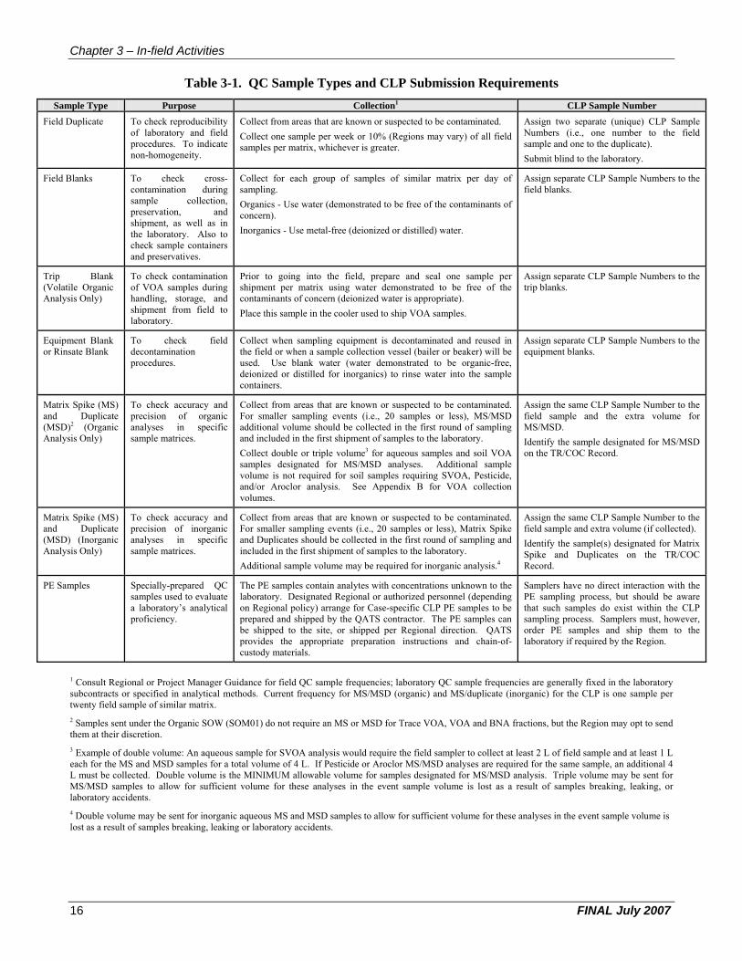
Chapter 3 – In-field Activities
Table 3-1. QC Sample Types and CLP Submission Requirements
Sample Type Purpose Collection1 CLP Sample Number
Field Duplicate To check reproducibility of laboratory and field procedures. To indicate non-homogeneity.
Collect from areas that are known or suspected to be contaminated. Collect one sample per week or 10% (Regions may vary) of all field samples per matrix, whichever is greater.
Assign two separate (unique) CLP Sample Numbers (i.e., one number to the field sample and one to the duplicate). Submit blind to the laboratory.
Field Blanks To check cross-contamination during sample collection, preservation, and shipment, as well as in the laboratory. Also to check sample containers and preservatives.
Collect for each group of samples of similar matrix per day of sampling. Organics - Use water (demonstrated to be free of the contaminants of concern). Inorganics - Use metal-free (deionized or distilled) water.
Assign separate CLP Sample Numbers to the field blanks.
Trip Blank (Volatile Organic Analysis Only)
To check contamination of VOA samples during handling, storage, and shipment from field to laboratory.
Prior to going into the field, prepare and seal one sample per shipment per matrix using water demonstrated to be free of the contaminants of concern (deionized water is appropriate). Place this sample in the cooler used to ship VOA samples.
Assign separate CLP Sample Numbers to the trip blanks.
Equipment Blank or Rinsate Blank
To check field decontamination procedures.
Collect when sampling equipment is decontaminated and reused in the field or when a sample collection vessel (bailer or beaker) will be used. Use blank water (water demonstrated to be organic-free, deionized or distilled for inorganics) to rinse water into the sample containers.
Assign separate CLP Sample Numbers to the equipment blanks.
Matrix Spike (MS) and Duplicate (MSD)2 (Organic Analysis Only)
To check accuracy and precision of organic analyses in specific sample matrices.
Collect from areas that are known or suspected to be contaminated. For smaller sampling events (i.e., 20 samples or less), MS/MSD additional volume should be collected in the first round of sampling and included in the first shipment of samples to the laboratory. Collect double or triple volume3 for aqueous samples and soil VOA samples designated for MS/MSD analyses. Additional sample volume is not required for soil samples requiring SVOA, Pesticide, and/or Aroclor analysis. See Appendix B for VOA collection volumes.
Assign the same CLP Sample Number to the field sample and the extra volume for MS/MSD. Identify the sample designated for MS/MSD on the TR/COC Record.
Matrix Spike (MS) and Duplicate (MSD) (Inorganic Analysis Only)
To check accuracy and precision of inorganic analyses in specific sample matrices.
Collect from areas that are known or suspected to be contaminated. For smaller sampling events (i.e., 20 samples or less), Matrix Spike and Duplicates should be collected in the first round of sampling and included in the first shipment of samples to the laboratory. Additional sample volume may be required for inorganic analysis.4
Assign the same CLP Sample Number to the field sample and extra volume (if collected). Identify the sample(s) designated for Matrix Spike and Duplicates on the TR/COC Record.
PE Samples Specially-prepared QC samples used to evaluate a laboratory’s analytical proficiency.
The PE samples contain analytes with concentrations unknown to the laboratory. Designated Regional or authorized personnel (depending on Regional policy) arrange for Case-specific CLP PE samples to be prepared and shipped by the QATS contractor. The PE samples can be shipped to the site, or shipped per Regional direction. QATS provides the appropriate preparation instructions and chain-ofcustody materials.
Samplers have no direct interaction with the PE sampling process, but should be aware that such samples do exist within the CLP sampling process. Samplers must, however, order PE samples and ship them to the laboratory if required by the Region.
1 Consult Regional or Project Manager Guidance for field QC sample frequencies; laboratory QC sample frequencies are generally fixed in the laboratory subcontracts or specified in analytical methods. Current frequency for MS/MSD (organic) and MS/duplicate (inorganic) for the CLP is one sample per twenty field sample of similar matrix. 2 Samples sent under the Organic SOW (SOM01) do not require an MS or MSD for Trace VOA, VOA and BNA fractions, but the Region may opt to send them at their discretion. 3 Example of double volume: An aqueous sample for SVOA analysis would require the field sampler to collect at least 2 L of field sample and at least 1 L each for the MS and MSD samples for a total volume of 4 L. If Pesticide or Aroclor MS/MSD analyses are required for the same sample, an additional 4 L must be collected. Double volume is the MINIMUM allowable volume for samples designated for MS/MSD analysis. Triple volume may be sent for MS/MSD samples to allow for sufficient volume for these analyses in the event sample volume is lost as a result of samples breaking, leaking, or laboratory accidents. 4 Double volume may be sent for inorganic aqueous MS and MSD samples to allow for sufficient volume for these analyses in the event sample volume is lost as a result of samples breaking, leaking or laboratory accidents.
16 FINAL July 2007

Chapter 3 – In-field Activities
3.1.1.1 Collect Field QC Samples Samplers can collect field QC samples and laboratory QC samples to verify that sample quality is maintained during a sampling project.
Field QC samples are designed to assess variability of the media being sampled and to detect contamination and sampling error in the field. The types of field QC samples that are generally collected include field duplicates and field blanks (such as equipment, trip, or rinse blanks). Generally, field duplicate samples should remain “blind” to the laboratory (i.e., they should have separate CLP Sample Numbers).
3.1.1.2 Collect Laboratory QC Samples A laboratory QC sample is an additional analysis of a field sample, as required by the laboratory’s contract. There are three types of laboratory QC samples:
• MS [for organic and inorganic samples]; • MSD [for organic samples only]; and • Duplicates [for inorganic samples only].
Samplers should obtain Regional guidance regarding the collection of MS and MSD samples (especially for organics analyses).
Samplers should select one sample per matrix per 20 samples as a “laboratory QC” sample. Designated organic laboratory QC samples should be noted on the Organic TR/COC Record. Designated inorganic laboratory QC samples should be noted on the Inorganic TR/COC Record. The laboratory QC sample must not be designated only in the “Field QC Qualifier” column on either the Organic or Inorganic TR/COC Records. Make sure that the laboratory QC sample is included in TR/COC Record samples to be used for the Laboratory QC field.
The sampler should select a field sample as the laboratory QC sample. If the sampler does not select a field sample as the laboratory QC sample, then it is possible that the laboratory could select the field blank (e.g., an equipment or rinsate blank) sample to meet contractual QC requirements. The use of field blanks for laboratory MS/MSD/Duplicate analysis reduces the usability of the data to assess data quality.
In the event of multiple sample shipments during a sampling event, it is recommended that the sampler submit laboratory QC samples in the first sample shipment.
3.1.2 Meet Volume, Preservation, and Holding Time Requirements
Samplers should refer to their project plans to obtain the specific sample volumes to be collected, the preservation needed for those samples, and the technical holding times under which they must submit samples to the scheduled CLP laboratory. Sample collection parameters (to include sample volumes, preservatives, and technical holding times) for organic collection and analysis are listed in Tables 3-2 and 3-3. Sample collection parameters for inorganic analysis and collection are listed in Table 3-4.
3.1.2.1 Collect Sample Volume Collecting sufficient sample volume is critical. There must be sufficient physical sample volume for the analysis of all required parameters and completion of all QC determinations. The type of analytical procedure(s) to be performed will often dictate the sample volume to collect. For example, each water sample collected for VOA analysis by CLP SOW SOM01 or ILM05 requires a minimum of three vials, each filled completely to a 40 mL capacity. See Appendix C for information regarding the collection of VOAs in water. It is extremely important that samplers refer to their specific project plans to identify and collect the correct sample volume during each sampling event.
When sampling for VOAs in soils, samplers must use SW-846 Method 5035A guidelines included in Appendix B.
FINAL July 2007 17

Chapter 3 – In-field Activities
3.1.2.2 Preserve Samples Degradation of some contaminants may occur naturally (e.g., VOAs). The sampler must chemically preserve some water samples for certain analytes before shipping them to the laboratory. The sampler should preserve and immediately cool all samples to 4°C (±2°C) upon collection and samples should remain cooled until the time of analysis (do not freeze water samples). Preservation techniques vary among Regions so the sampler should obtain Region-specific instructions and review the appropriate project plans and SOPs. See Appendix C for information regarding the collection of VOAs in water.
3.1.2.3 Ship within Holding Times Samplers should ship samples to scheduled CLP laboratories as soon as possible after collection. Daily shipment of samples to CLP laboratories is preferred whenever possible. If samples cannot be shipped on a daily basis, they must be properly preserved and maintained to meet CLP-specified temperatures, holding times, and custody requirements.
The technical holding times are the maximum time allowed between a sample collection and the completion of the sample extraction and/or analysis. In contrast, contractual holding times are the maximum lengths of time that the CLP laboratory can hold the sample prior to extraction and/or analysis. These contractual holding times are described in the appropriate CLP SOW. Contractual holding times are shorter than the technical holding times to allow for sample packing and shipping.
If samplers are shipping samples after 5:00 PM ET, they must notify the RSCC (or designee) or SMO by 8:00 AM ET on the following business day. When making a Saturday delivery, samplers shall contact the RSCC (or designee) or SMO by 3:00 PM ET on the Friday prior to delivery.
FINAL July 2007 18
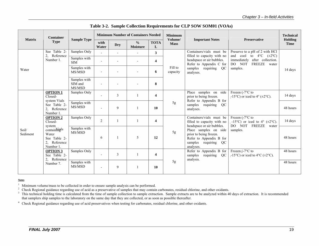
Chapter 3 – In-field Activities
Table 3-2. Sample Collection Requirements for CLP SOW SOM01 (VOAs)
Matrix Container Type Sample Type
Minimum Number of Containers Needed Minimum Volume/
Mass Important Notes Preservative
Technical Holding
Timewith Water Dry %
Moisture TOTA
L See Table 22, Reference
Samples Only - - - 3
Fill to capacity
Containers/vials must be filled to capacity with no headspace or air bubbles. Refer to Appendix C for samples requiring QC analyses.
Preserve to a pH of 2 with HCl and cool to 4°C (±2ºC) immediately after collection. DO NOT FREEZE water samples. 14 days
Number 1. Samples with SIM - - - 4
Water Samples with MS/MSD - - - 6
Samples with SIM and MS/MSD
- - - 8
OPTION 1 Closed-
Samples Only - 3 1 4
Place samples on side prior to being frozen.
Frozen ( 7°C to - 15°C) or iced to 4° (±2°C). 14 days
system Vials See Table 22, Reference Number 1.
Samples with MS/MSD - 9 1 10
5g Refer to Appendix B for samples requiring QC analyses. 48 hours
OPTION 2 Closed
Vials
Samples Only 2 1 1 4
Containers/vials must be filled to capacity with no headspace or air bubbles.
Frozen ( 7°C to -15°C) or iced to 4° (±2°C). DO NOT FREEZE water
14 days
Soil/ Sediment
systemcontaining Water See Table 22, Reference Number 1.
Samples with MS/MSD
6 1 5 12 5g Place samples on side
prior to being frozen. Refer to Appendix B for samples requiring QC analyses.
samples.
48 hours
OPTION 3 See Table 22, Reference Number 7.
Samples Only - 3 1 4
5g
Refer to Appendix B for samples requiring QC analysis.
Frozen (-7°C to - 15°C) or iced to 4°C (±2°C).
48 hours
Samples with MS/MSD - 9 1 10
48 hours
Notes
1 Minimum volume/mass to be collected in order to ensure sample analysis can be performed. 2 Check Regional guidance regarding use of acid as a preservative of samples that may contain carbonates, residual chlorine, and other oxidants. 3 This technical holding time is calculated from the time of sample collection to sample extraction. Sample extracts are to be analyzed within 40 days of extraction. It is recommended
that samplers ship samples to the laboratory on the same day that they are collected, or as soon as possible thereafter. 4 Check Regional guidance regarding use of acid preservatives when testing for carbonates, residual chlorine, and other oxidants.
FINAL July 2007 19

Chapter 3 – In-field Activities
Table 3-3. Sample Collection Requirements for CLP SOW SOM01 (SVOAs, Pesticides and Aroclors)
Analysis Matrix Containers Minimum Volume/ Mass Important Notes Preservative
Technical Holding
Time
Semivolatile Analytes
Water See Table 2-2, Reference Number 5. 2L If amber containers are not available, the samples should be protected from light.
Cool all samples to 4°C (±2°C) immediately after collection. DO NOT FREEZE water samples.
7 days
Soil/ Sediment
See Table 2-2, Reference Numbers 3 and 4. Fill to capacity Cool all samples to 4°C (±2°C)
immediately after collection. 14 days
Pesticides/ Aroclors
Water See Table 2-2, Reference Number 5. 2L If amber containers are not available, the samples should be protected from light.
Cool all samples to 4°C (±2°C) immediately after collection. DO NOT FREEZE water samples.
7 days
Soil/ Sediment
See Table 2-2, Reference Numbers 3 and 4. Fill to capacity Cool all samples to 4°C (±2°C)
immediately after collection. 14 days
Notes
1 Minimum volume/mass to be collected in order to ensure sample analysis can be performed. 2 Check Regional guidance regarding use of acid as a preservative of samples that may contain carbonates, residual chlorine, and other oxidants. 3 This technical holding time is calculated from the time of sample collection to sample extraction. Sample extracts are to be analyzed within 40 days of extraction. It is recommended
that samplers ship samples to the laboratory on the same day that they are collected, or as soon as possible thereafter. 4 Check Regional guidance regarding use of acid preservatives when testing for carbonates, residual chlorine, and other oxidants.
FINAL July 2007 20

Chapter 3 – In-field Activities
Table 3-4. Sample Collection Requirements for CLP SOW ILM05
Analysis Matrix Containers Minimum Volume/ Mass1 Important Notes Preservative
Technical Holding Time4
Metals/ICPAES and/or Mercury by CVAA
Water See Table 2-2, Reference Number 2. 1L If collecting for both ICP-AES AND ICP-MS methods, a separate 1L volume of sample must be collected for each method per sample location.
Acidify to pH < 2 with HNO3 and cool to 4°C (±2°C) immediately after collection.2
DO
NOT FREEZE water samples.
6 months for all metals except Mercury (28 days)
Soil/ Sediment
See Table 2-2, Reference Number 3. Fill to capacity Cool to 4°C (±2°C) immediately after collection.
6 months
Cyanide/ Spectrophoto metric Determination 3
Water See Table 2-2, Reference Number 2. 1L To neutralize residual chlorine, immediately upon collection, add 0.6 g ascorbic acid for each liter of sample collected. Add NaOH until pH >12 and cool to 4°C (±2°C) immediately after collection.5 DO NOT FREEZE water samples.
14 days
Soil/ Sediment
See Table 2-2, Reference Number 3. Fill to capacity Cool to 4°C (±2°C) immediately after collection.
14 days
Notes
1 Minimum volume/mass to be collected in order to ensure sample analysis can be performed. 2 Check Regional guidance regarding use of acid as a preservative of samples that may contain carbonates, residual chlorine, and other oxidants. 3 Samplers must test for sulfide and oxidizing agents (e.g., chlorine) in aqueous samples in the field upon collection. Please refer to the SAP and Appendix C for guidance. Sulfides
adversely affect the analytical procedure. The following can be done to test for and neutralize sulfides. Place a drop of the sample on lead acetate test paper to detect the presence of sulfides. If sulfides are present, treat 25 mL more of the sample than that required for the cyanide determination with powdered cadmium carbonate or lead carbonate. Yellow cadmium sulfide or black lead sulfide precipitates if the sample contains sulfide. Repeat this operation until a drop of the treated sample solution does not darken the lead acetate test paper. Filter the solution through a dry filter paper into a dry beaker, and from the filtrate measure the sample to be used for analysis. Avoid a large excess of cadmium carbonate and a long contact time in order to minimize a loss by complication or occlusion of cyanide on the precipitated material. Sulfide removal should be performed in the field, if practical, prior to pH adjustment with NaOH.
4 This technical holding time is calculated from the time of sample collection to sample extraction. Sample extracts are to be analyzed within 40 days of extraction. It is recommended that samplers ship samples to the laboratory on the same day that they are collected, or as soon as possible thereafter.
FINAL July 2007 21
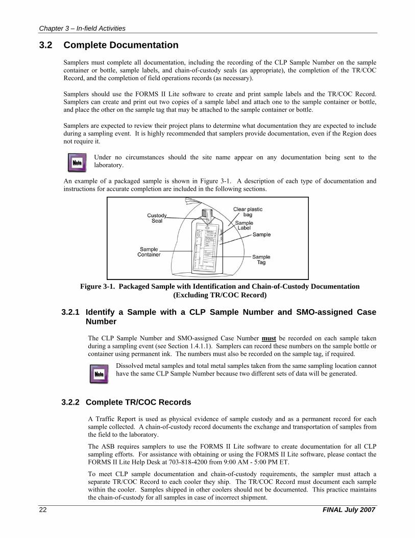
Chapter 3 – In-field Activities
3.2 Complete Documentation
Samplers must complete all documentation, including the recording of the CLP Sample Number on the sample container or bottle, sample labels, and chain-of-custody seals (as appropriate), the completion of the TR/COC Record, and the completion of field operations records (as necessary).
Samplers should use the FORMS II Lite software to create and print sample labels and the TR/COC Record. Samplers can create and print out two copies of a sample label and attach one to the sample container or bottle, and place the other on the sample tag that may be attached to the sample container or bottle.
Samplers are expected to review their project plans to determine what documentation they are expected to include during a sampling event. It is highly recommended that samplers provide documentation, even if the Region does not require it.
Under no circumstances should the site name appear on any documentation being sent to the laboratory.
An example of a packaged sample is shown in Figure 3-1. A description of each type of documentation and instructions for accurate completion are included in the following sections.
Figure 3-1. Packaged Sample with Identification and Chain-of-Custody Documentation (Excluding TR/COC Record)
3.2.1 Identify a Sample with a CLP Sample Number and SMO-assigned Case Number
The CLP Sample Number and SMO-assigned Case Number must be recorded on each sample taken during a sampling event (see Section 1.4.1.1). Samplers can record these numbers on the sample bottle or container using permanent ink. The numbers must also be recorded on the sample tag, if required.
Dissolved metal samples and total metal samples taken from the same sampling location cannot have the same CLP Sample Number because two different sets of data will be generated.
3.2.2 Complete TR/COC Records
A Traffic Report is used as physical evidence of sample custody and as a permanent record for each sample collected. A chain-of-custody record documents the exchange and transportation of samples from the field to the laboratory.
The ASB requires samplers to use the FORMS II Lite software to create documentation for all CLP sampling efforts. For assistance with obtaining or using the FORMS II Lite software, please contact the FORMS II Lite Help Desk at 703-818-4200 from 9:00 AM - 5:00 PM ET.
To meet CLP sample documentation and chain-of-custody requirements, the sampler must attach a separate TR/COC Record to each cooler they ship. The TR/COC Record must document each sample within the cooler. Samples shipped in other coolers should not be documented. This practice maintains the chain-of-custody for all samples in case of incorrect shipment.
FINAL July 2007 22
Chapter 3 – In-field Activities
If more than one TR/COC Record is used for the samples within one cooler, all of the records must have complete header information and original signatures. Samplers are responsible for the care and custody of samples from the time of collection to the time of shipment to the laboratories for analysis. A sample is considered under custody if:
• It is in possession or in view after being in possession; • It was in possession and then secured or sealed to prevent tampering; or • It was in possession when placed in a secured area.
Each time the custody of samples is turned over to another person, the TR/COC Record must be signed off by the former custodian and accepted by the new custodian. Samplers are, therefore, responsible for properly completing any forms or other Region-required documentation used to establish the chain-ofcustody for each sample during a sampling event.
3.2.2.1 Complete a TR/COC Record Using the FORMS II Lite Software Once the sampler inputs sample collection information into FORMS II Lite, a TR/COC Record will be generated electronically. The software automatically displays only the information to be entered by the sampler. FORMS II Lite then generates a laboratory and a Regional copy of the TR/COC Record (see Figures 3-2 through 3-5). The sampler can print out multiple copies of the TR/COC Record as necessary. The sampler must sign and submit original copies of the TR/COC Record as appropriate.
An electronic TR/COC Record created using the FORMS II Lite software contains basic header information; however, the sampler can also include some additional detailed information. For example, not only is the sample matrix listed on the electronic TR/COC Record, but the name of the sampler taking the sample can also be entered. Samplers should note that certain information will not appear on the electronic TR/COC Record (e.g., matrix and preservative descriptions).
3.2.2.2 Indicate Modified Analysis on FORMS II Lite TR/COC Records When completing a TR/COC Record using FORMS II Lite, the sampler should identify any samples that will be analyzed using a CLP Modified Analysis. Samplers should indicate use of a Modified Analysis by creating a new analysis within the FORMS II Lite Wizard or through the FORMS II Lite Reference Tables. This newly-created analysis should contain the Modification Reference Number within the name assigned to the analysis. For example, if a Region submits a Modified Analysis for an additional analyte, and SMO assigns the Modification Reference Number 1301.0, the FORMS II Lite analysis could be named "VOA by M.A. 1301.0". The associated abbreviation for this analysis could be "VOA M.A.". If you have any questions regarding identification of Modified Analysis using FORMS II Lite, please contact the FORMS II Lite Help Desk at 703-818-4200 from 9:00 AM - 5:00 PM ET.
3.2.2.3 Make Manual Edits to Printed FORMS II Lite TR/COC Records If a FORMS II Lite TR/COC Record has been printed and deletions or edits need to be made by the sampler, the following procedures must be followed:
• If making a deletion, manually cross out the information to be disregarded from the TR/COC Record, initial and date the deletion.
• If making an addition, enter the new information and initialsign and date the newly added information.
All modifications made on a printed TR/COC Record must be initialed and dated.
FINAL July 2007 23

Chapter 3 – In-field Activities
Figure 3-2. Organic Traffic Report & Chain of Custody Record (Laboratory Copy)
FINAL July 2007 24
IV i ~
Date ShlpPlld:
Carrier Nama:
Ai rblll:
Shipped to:
ORGANIC SAMPtE No.
C0075
00076
COOH
Shlpm4ll1\ for Case Comp~te?N
USEPA Contract Laboratory Program Organic Traffic Report & Chain of Custody Record
2/2012001 Chain o f Custody Record ~mpler
DHL Slg]1atlJrtr.
Relinquished By (Dale I Time) Reoeived By 121212
1 Organic Laboratory 1234 Smith Drive 2 Anywhere. USA 12345 (123) 456-7890 3
4
MAlRXI CONC, AN/H.Y~SI TAG"'oJ STATION SA'MPLER liYPE TURMA.ROUND PRESERVATI\I1:I Bottles L.OCATION
Industrial HIC BNNPEST (21), VOA 6486, 6487 (2) LOCATION ONE Process (21) Wastewa.terl BOSBY SAMPLER Ground Waterl LJC BNAIPEST (21). VOA 6494, 6495 (2) LOCATION TWO JOE SAMPLER (21)
Industrial Effluent MIG BNAIPEST (21). VOA 6502, 6503 (2) LOCATION ONE Wastewaterl (21) JOE SAMPLER
Sampla(s) to ba usad for laboratory QC: Additional Sampler Signature(s) :
C0077
Case No: 39400 DAS No: DAS9000 L SOGNo:
I
For lab Use Only
(Dale I Time) I Lab Contract No:
Unit Price:
I Transfer To:
I Lab C,ontract No:
I Unit Price:
SAMPlE COllECT INORGANIC FOR !.AB Us!; ONl Y DATEITIME SAMPLE No. Sample Conclltlon On Ailcelpt
S: 212012001 16:02
E: 2123/2001 16:02
S; 2120/2001 16:01
E: 212112001 16:01
S: 2116/2001 15:55
E: 212012001 15:55
Cooklr TllTlpeniture Upon Reo;(lipt:
MCOO75
MC0076
MCOO77
Chain of Custody Seal Number:
A.naly,sls Key : Concentration : L = low, M = Low/Medium. H = High Ty pe/Designate: Composite = C, Grab = G Custody Seal lintact? _ Shipmant Iced?
BNAfPEST = CLP TCL Semivolatiles and PeslicideslPC, VOA = CLP TeL Volatiles
TR Number: 3-1 03823254·022001 -0001 1'1115.1.047 Page 1 of 1

Chapter 3– In-field Activities
Figure 3-3. Inorganic Traffic Report & Chain of Custody Record (Laboratory Copy)
FINAL July 2007 25
&EPA Date Shlpp&d:
CarriGr Name:
Airblll:
Shipped to:
INORGANIC SAMPLE No.
MC007S
MCOO76
MCOOn
ShlplTKllll foreaso Comple"'itI
USEPA Contract Laboratory Progra m Inorganic Traffic Report &. Chain of Custody Record
2/2012001 Chain of Custody Record Sampler
DHL Sig:nal:U1'e:
Relinquished B)I (Date I Time) Reoeived ey 121212
1 Inorganic Laboratory 1234 Smith Olive 2 Anywhere, USA 12345 (123) 456-7890 3
4
MATRIX! CONel ANALYSIS) TAGNoJ STATION SAMPLE~ TYPE TURK6.ROUND PRESERVATIVE! Boilles LOCATION
Industrial H/C AI (21), Ba (21), Ca 6481 . 6482, 6483, 6484, LOCATION ONE Process (21 ), Cr (21 ), TM/CN 6485 (5) Wastews.terl (21) BOBBY SAMPLER Ground Waterl UC AI (21), Ba (21), Ca 6489, 6490, 6491 , 6492, LOCATION TWO JOE SAMPLER (21), Cr (21), TM/CN 6493 (5)
(21) Industrial Effluen,t MIG AI (21), Ba (21), Ca 6497, 6498, 6499, 6500, LOCATION ONE Wa~rewaterl (21 ), Cr (21 ), TM/CN 6501 (5) JOE SAMPLER (21)
Sampla(s) to ba used lor laboratory QC: AdditIonal Sampler Signature(s):
MCOO77
Case No: 39400 OAS No: OAS9000 L SOGNo:
For Lab Use Only
(O.ate I Time) Lab Contract No:
I Un it Pnce:
I Transfar To:
I Lab c.ontract No:
Unit Pnce:
SAMPlE COlLECT ORGANIC FOR LAB USE ONLY DATEITIME SAMPLE No. Sample Condition On Receipt
S; 212012001 16:02
E: 212312001 16:02
S; 212012001 16:01
E: 212112001 16:01
S; 211612001 15:55
E: 212012001 15:55
Cooklr Tampara!u:11I UpanRoc;e!pt:
C007S
C0076
coon
Chain of C.ustody Seal Number:
Ana lysis Key ; Concerlltatlon; L -law, M;;; Low/Medium. H;;; High Type/Designate: Composite " C, Grab" G Custody Seal llntact7 _ Shipmant Icod? _
AI = Aluminum, Sa = Barium, Ca = Calcium, Cr = Chromium, TM/CN = CLP TP\L Total Metals and Cyanide
TR Number.: 3 .. 103823254 .. 022001 ·0003 f2V5.1. 047 Page 1 of 1
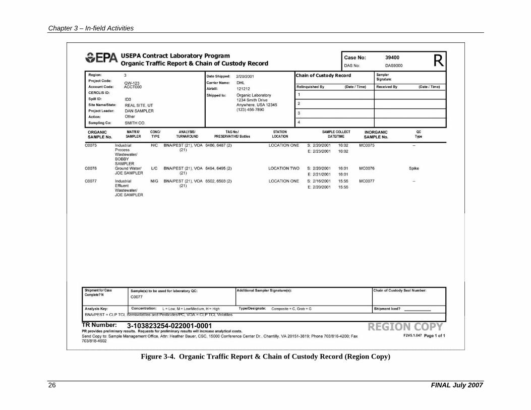
Chapter 3 – In-field Activities
Figure 3-4. Organic Traffic Report & Chain of Custody Record (Region Copy)
FINAL July 2007 26
0 1' Region :
Project Code:
AccQunt Code:
CERCLIS 10:
Spill 10:
USEPA Contract Laboratory Program Organic Traffic Report & Chain of Ou,stody Record
3
QW-123 ACCTOOO
IOJ
Date Shipped: 212012001
Carrier Name: DHL
Air'blll ~ 121.212
Shipped to:
Case No:
DAS No:
I Chain of Custody Record
I Relinquishedl By (Date I Tirnel
39400
DAS9000
Sampler Signature:
Rec~ived By
Site Name/State: REAL SITE, UT DAN SAMPLER
Oll1er
Organic Laborato.ry 1234 Smith Drive Anywhere, USA 12345 (123) 456-7890
2
Project Leade'r :
Aclion :
Silmpling! C·o: SMITH CO.
ORGANIC MATRIX! CONCI SAMPLE No. SAMPlER TYf'IE
COO75 Industrial HlC Process Wastewaterl BOBBY SAMPLER
COO76 Ground Waterl UC JOE SAMPLER
coon Industrial MIG Effluent Wastewaterl JOE SAMPLER
ANALY SIS ' TAO No) TURNAROUND PRESERVA TlVE/Bolllos
BNAIPEST (21). VOA 6486. 6467 (2) (21)
BNA/PEST (21). VOA 6494. 6495 (2) (21 )
BNA/PEST (21). VOA 6502. 6503 (2) (21)
STATIO,N LOCAfiON
4
lOCATION ONE
LOCATION TWO
lOCATION ONE
SAMPlE COWLEi DATElTIME
$ ; 212012001 16:02 E: 212312001 16:02
S; 2/2012001 16:01:
E: 2121/2001 16:01
S; 2/1612001 15:55 E: 212012001 15:55
INORGANilC SAMPLE No.
MCOQ75
MCOO7S
MCOOn
R (Date 'Time)
QC 1)'110
Spike
SIll pmen.tfor Case Complete?N
Sample(s) to be u"d for laboratory QC: Additional Samplor Signature(s): Chain of Custody Seal :Numbor:
C0077
Analysis Key~ Concentration: L" tow, M" Low/Medium, H" foIlgh TypeJOesignate: Composite" C, G"rab .. G
BNAJPEST = CLP Tel
TR Number.: 3·103823254·022001 ·0001 PR provide:> preliminary re:>ults. Req'uests fo r preliminary results 'NUl increa::>e analyt ical (;osts.
Send Copy 10: Sample Management Office. Attn: Heather Bauer, CSC, 15000 Conference Center Dr .• Chantilly, VA 20151-3819; Phone 703/8 18-4200; Fax 703/818-4602
Shipment Iced?
REG y F2V5.1.047 Page 1: of 1
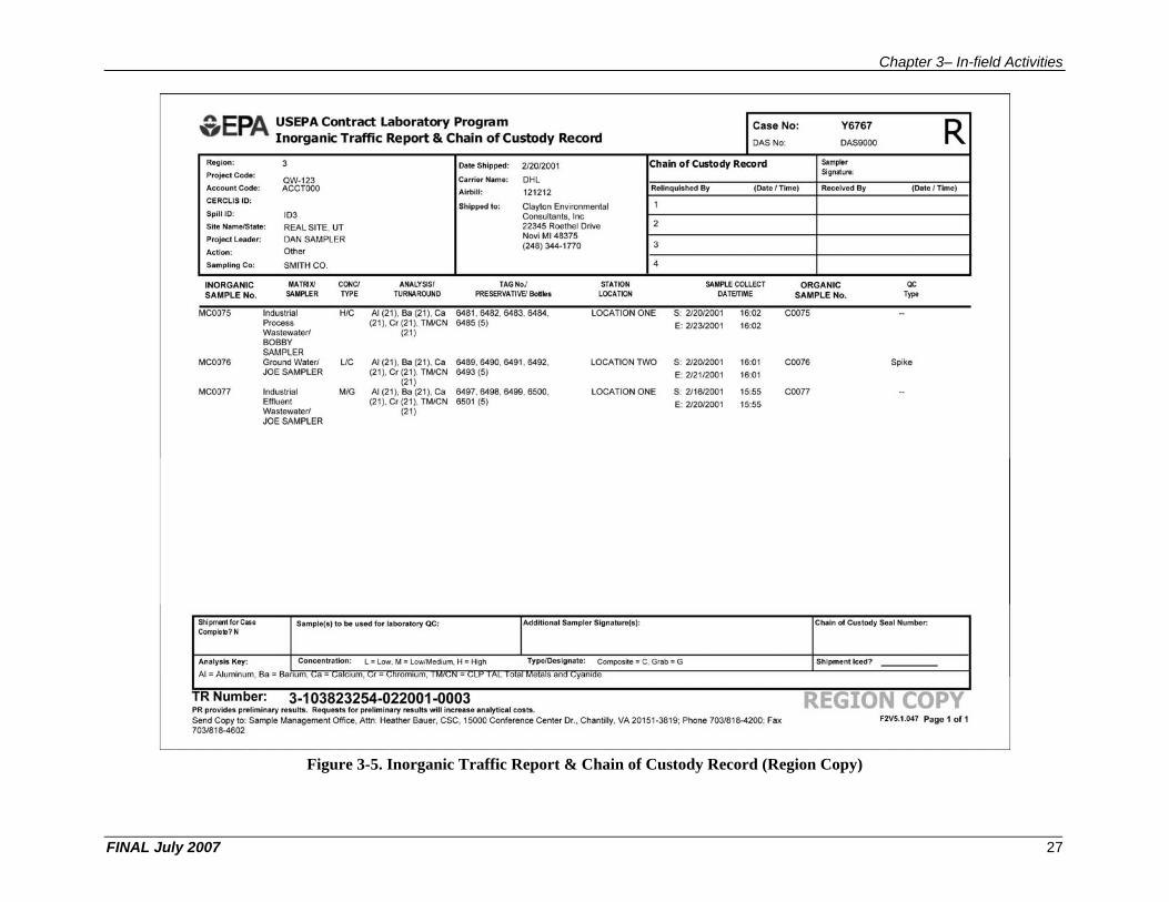
Chapter 3– In-field Activities
Figure 3-5. Inorganic Traffic Report & Chain of Custody Record (Region Copy)
FINAL July 2007 27
Reglon:
P roject Code:
Aeeou'Jlt Code;
CERCLIS 10:
S,pill ID:
Site N~m.",fState;
Projecll..eador:
Aclilon:
Sampling C·o:
USEPA Contract Laboratory Program Inorganic Traffic iRe port It Chain of Custody Record
QW·123 ACCTOQO
103
REAL SITE, UT
OAN SAMPLER Oti'l,er
SMITH ca.
Date Shipped: 212012001 Carrier N.,lIle: DHl
Alrb lll : 121212
, Shipped to; Clayton Environmental Consulta nm, l nc 22345 Roelhel Drive No,lIi M I 48375 (2.48) 344~1 770
Case No:
DAS No:
Chain of Custody Record
(D~te I Time)
2
3
4
Y6767
DASSOOO
Sam~r Signature:
ReCleived By
IINOR,G.ANIC MAtRIX! OONCI AAALy'SjSI TAGNoJ STATtON SAMPLE COLlECT ORGANIC SAMPLE No.
MC0075
MC0076
MCOO71
Shi pment ror ease Compfo»? N
SAMPlER TYPE TURNA.ROOND
Industrial H/C AI (21), 8a (21), Cs Process (2 1), Cr (21), lM/CN Wastewaterl (21) BOBBY SAMPLER Ground Waterl UC AI (21) , Ba (21), Ca JOE SAMPLER (21), Cr (21 ). lM/CN
(21) Industrial MIG AI (21), Sa (21), Ca Effluent (21), Cr (2 11), lM/CN Wastewate<rl (21) JOE SAMPLER
Sample!,.) to be Y'ied for IItborator)' QC,
PRESERVAlilVEI BoiIJ1es LOCATION OATCIllME
6481 , 6482, 6483, 6484, LOCA l"ION ONE S : 2/2012001 16:02 6485 (5) E: 2/231'2001 16:02
6489, 6490, 6491 , 6492, LOCATION TWO S: 2/2012001 16:01 6493 (5) E: 212112001 1,6:01
6497, 6498, 6499', 6500, LOCA liON ONE $ ; 2/1612001 15;55 6501 (5) E: 2/2012001 15:55
Additlonall S.ampler Slgnalura(s):
Analysis Key: Con~ntra,lion: l. - Ilow. M " low/Medium. H " High TypeJiDes.lgna.1e: Composite " C, Grab" G
AI '" Aluminum, Ba '" eanum, _ :;Ii '" _ a Clum, r'" _ rOmll)m,
TR Numbe.r: 3 .. 103823254 .. 022001 .. 0003 PR. proviciu preliminary resulllI . RequKIS for preliminary results. w1U Increase analytrcal costs.
Send Copy to: Sampfe Management Office, Atm: Heather Bauer, CSC, 15000 Conference Center Dr., Chantilly, VA 20151 -3819; Phone 7031818-4200; Fax 70318184602
5.AMPLENo.
C0075
C0076
coon
Shfpmeot Iced?
R (Date lnme)
Spike
F:2VS.1.D47 Page 1 of1
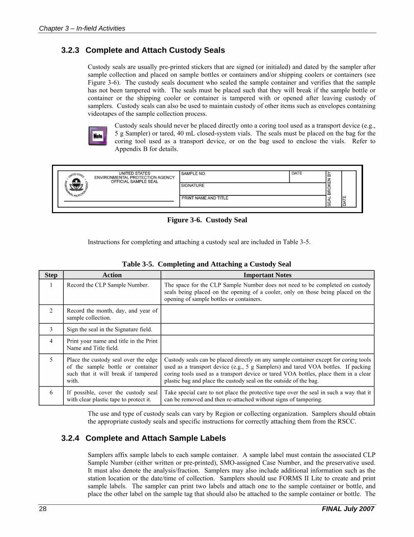
Chapter 3 – In-field Activities
3.2.3 Complete and Attach Custody Seals
Custody seals are usually pre-printed stickers that are signed (or initialed) and dated by the sampler after sample collection and placed on sample bottles or containers and/or shipping coolers or containers (see Figure 3-6). The custody seals document who sealed the sample container and verifies that the sample has not been tampered with. The seals must be placed such that they will break if the sample bottle or container or the shipping cooler or container is tampered with or opened after leaving custody of samplers. Custody seals can also be used to maintain custody of other items such as envelopes containing videotapes of the sample collection process.
Custody seals should never be placed directly onto a coring tool used as a transport device (e.g., 5 g Sampler) or tared, 40 mL closed-system vials. The seals must be placed on the bag for the coring tool used as a transport device, or on the bag used to enclose the vials. Refer to Appendix B for details.
Figure 3-6. Custody Seal
Instructions for completing and attaching a custody seal are included in Table 3-5.
Table 3-5. Completing and Attaching a Custody Seal Step Action Important Notes
1 Record the CLP Sample Number. The space for the CLP Sample Number does not need to be completed on custody seals being placed on the opening of a cooler, only on those being placed on the opening of sample bottles or containers.
2 Record the month, day, and year of sample collection.
3 Sign the seal in the Signature field.
4 Print your name and title in the Print Name and Title field.
5 Place the custody seal over the edge of the sample bottle or container such that it will break if tampered with.
Custody seals can be placed directly on any sample container except for coring tools used as a transport device (e.g., 5 g Samplers) and tared VOA bottles. If packing coring tools used as a transport device or tared VOA bottles, place them in a clear plastic bag and place the custody seal on the outside of the bag.
6 If possible, cover the custody seal with clear plastic tape to protect it.
Take special care to not place the protective tape over the seal in such a way that it can be removed and then re-attached without signs of tampering.
The use and type of custody seals can vary by Region or collecting organization. Samplers should obtain the appropriate custody seals and specific instructions for correctly attaching them from the RSCC.
3.2.4 Complete and Attach Sample Labels
Samplers affix sample labels to each sample container. A sample label must contain the associated CLP Sample Number (either written or pre-printed), SMO-assigned Case Number, and the preservative used. It must also denote the analysis/fraction. Samplers may also include additional information such as the station location or the date/time of collection. Samplers should use FORMS II Lite to create and print sample labels. The sampler can print two labels and attach one to the sample container or bottle, and place the other label on the sample tag that should also be attached to the sample container or bottle. The
FINAL July 2007 28
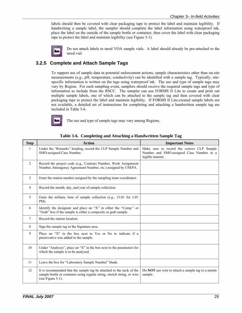
Chapter 3– In-field Activities
labels should then be covered with clear packaging tape to protect the label and maintain legibility. If handwriting a sample label, the sampler should complete the label information using waterproof ink, place the label on the outside of the sample bottle or container, then cover the label with clear packaging tape to protect the label and maintain legibility (see Figure 3-1).
Do not attach labels to tared VOA sample vials. A label should already be pre-attached to the tared vial.
3.2.5 Complete and Attach Sample Tags
To support use of sample data in potential enforcement actions, sample characteristics other than on-site measurements (e.g., pH, temperature, conductivity) can be identified with a sample tag. Typically, site-specific information is written on the tags using waterproof ink. The use and type of sample tags may vary by Region. For each sampling event, samplers should receive the required sample tags and type of information to include from the RSCC. The sampler can use FORMS II Lite to create and print out multiple sample labels, one of which can be attached to the sample tag and then covered with clear packaging tape to protect the label and maintain legibility. If FORMS II Lite-created sample labels are not available, a detailed set of instructions for completing and attaching a handwritten sample tag are included in Table 3-6.
The use and type of sample tags may vary among Regions.
Table 3-6. Completing and Attaching a Handwritten Sample Tag
Step Action Important Notes 1 Under the “Remarks” heading, record the CLP Sample Number and
SMO-assigned Case Number. Make sure to record the correct CLP Sample Number and SMO-assigned Case Number in a legible manner.
2 Record the project code (e.g., Contract Number, Work Assignment Number, Interagency Agreement Number, etc.) assigned by USEPA.
3 Enter the station number assigned by the sampling team coordinator.
4 Record the month, day, and year of sample collection.
5 Enter the military time of sample collection (e.g., 13:01 for 1:01 PM).
6 Identify the designate and place an “X” in either the “Comp.” or “Grab” box if the sample is either a composite or grab sample.
7 Record the station location.
8 Sign the sample tag in the Signature area.
9 Place an “X” in the box next to Yes or No to indicate if a preservative was added to the sample.
10 Under “Analyses”, place an “X” in the box next to the parameters for which the sample is to be analyzed.
11 Leave the box for “Laboratory Sample Number” blank.
12 It is recommended that the sample tag be attached to the neck of the sample bottle or container using regular string, stretch string, or wire (see Figure 3-1).
Do NOT use wire to attach a sample tag to a metals sample.
FINAL July 2007 29

Chapter 3 – In-field Activities
An example of a completed sample tag is included in Figure 3-7 below:
Figure 3-7. Completed Sample Tag
3.3 Provide Sample Receipt
After samples have been taken from private property, the sampler should prepare a receipt for these samples and provide this receipt to the property owner. This is especially important when sampling on private property since these samples could be used during future litigation and the receipt will verify that the owner granted approval for the removal of the samples from the property. An example of a sample receipt created using FORMS II Lite is shown in Figure 3-8.
Figure 3-8. Sample Receipt Created Using the FORMS II Lite Software
FINAL July 2007 30

Chapter 3– In-field Activities
3.4 Pack and Ship Samples
Once the samples have been collected, it is very important that the sampler properly package the samples for shipment and ensure that the samples are sent to the appropriate laboratory as quickly as possible. Prompt and proper packaging of samples will:
• Protect the integrity of samples from changes in composition or concentration caused by bacterial growth or degradation from increased temperatures;
• Reduce the chance of leaking or breaking of sample containers that would result in loss of sample volume, loss of sample integrity, and exposure of personnel to toxic substances; and
• Help ensure compliance with shipping regulations.
3.4.1 Sample Containers
Once samples are collected, they must be stored in conditions that maintain sample integrity. All samples should be placed in shipping containers or other suitable containers with ice to reduce the temperature as soon as possible after collection. Ideally, all samples should be shipped the day of collection for overnight delivery to the laboratory. If samples cannot be shipped on the day of collection, the sample temperature should be maintained at 4°C (±2°C) until they are shipped to the laboratory.
One CLP RAS sample may be contained in several bottles and vials. For example, one soil sample may consist of all containers needed for three of the analytical fractions available under this service (i.e., SVOA fraction, Pesticide fraction, and Aroclor fraction), even though the fractions are collected in separate containers. Therefore, the analysis to be performed and the matrix type will determine the type of container(s) that will be used, as well as the volume that must be collected for that particular sample fraction.
3.4.2 Inventory of Samples and Documentation
Prior to shipment, samplers should conduct an inventory of the contents of the shipping cooler or container against the corresponding TR/COC Record when packing for shipment to laboratories. An inventory will ensure that the proper number of containers have been collected for each analysis of the samples, that the required PE and QC samples and cooler temperature blanks are included, and the correct Sample Numbers and fractions have been assigned to each sample.
3.4.3 Shipping Regulations
Sample shipping personnel are legally responsible for ensuring that the sample shipment will comply with all applicable shipping regulations. For example, hazardous material samples must be packaged, labeled, and shipped in compliance with all IATA Dangerous Goods regulations or DOT regulations and USEPA guidelines. Refer to Appendix B for detailed shipping guidelines when using SW-846 Method 5035A to preserve and ship samples.
3.4.4 Sample Packaging for Shipment
Samplers are responsible for the proper packaging of samples for shipment. To ensure that samples are appropriately packaged (e.g., to avoid breakage and/or contamination) the sampler should consult their respective project plans to determine the proper packing and shipping procedures. The sampler must determine the sample type, pack the shipping containers correctly, include necessary paperwork, label and seal shipping containers or coolers, and ship the samples.
3.4.4.1 Determine the Sample Type and Container Samplers should know what kinds of samples they are handling to ensure proper packaging. Samplers should refer to their appropriate project plans to determine which type of sample container should be used for each type of sample being taken during the sampling event.
FINAL July 2007 31

Chapter 3 – In-field Activities
Please follow Regional guidance with reference to samples containing dioxin or radioactive waste.
3.4.4.2 Pack Shipping Containers It is imperative that samples are correctly and carefully packed in shipping containers to prevent the sample containers from breaking or leaking. Samplers must prepare and pack a shipping cooler or container according to the instructions outlined in Table 3-7.
Table 3-7. Packing Samples for Shipment Step Action Important Notes
1 Seal all drain holes in the shipping container, both inside and out, to prevent leakage in the event of sample breakage.
2 Check all lids/caps to make sure the samples are tightly sealed and will not leak.
3 Seal samples within a clear plastic bag. Custody seals can be placed directly on any sample container except for coring tools used as a transport device (e.g., 5 g Samplers) and tared VOA bottles. If packing coring tools used as a transport device or tared VOA bottles, place them in a clear plastic bag and place the custody seal on the outside of the bag.
4 Fully chill samples to 4°C (±2°C) prior to placement within suitable packing materials.
5 Prior to placing samples within the shipping cooler, it is recommended that samplers line shipping containers with noncombustible, absorbent packing material.
6 Place samples in CLEAN, sealed, watertight shipping containers (metal or hard plastic coolers).
7 Conduct an inventory of the contents of the shipping cooler/container against the corresponding TR/COC Record.
8 Cover samples in double-bagged ice to prevent water damage to packing materials.
Do NOT pour loose ice directly into the sample cooler. The ice is used to maintain the temperature of the samples within the shipping cooler.
9 It is recommended a temperature blank be included within each cooler being shipped.
The temperature blank is generally a 40 L vial filled with water and labeled “temperature blank” but does not have a Sample Number.
10 Ensure that the site name or other site-identifying information does not appear on any documentation being sent to the laboratory.
The laboratory should not receive any site-identifying information.
FINAL July 2007 32
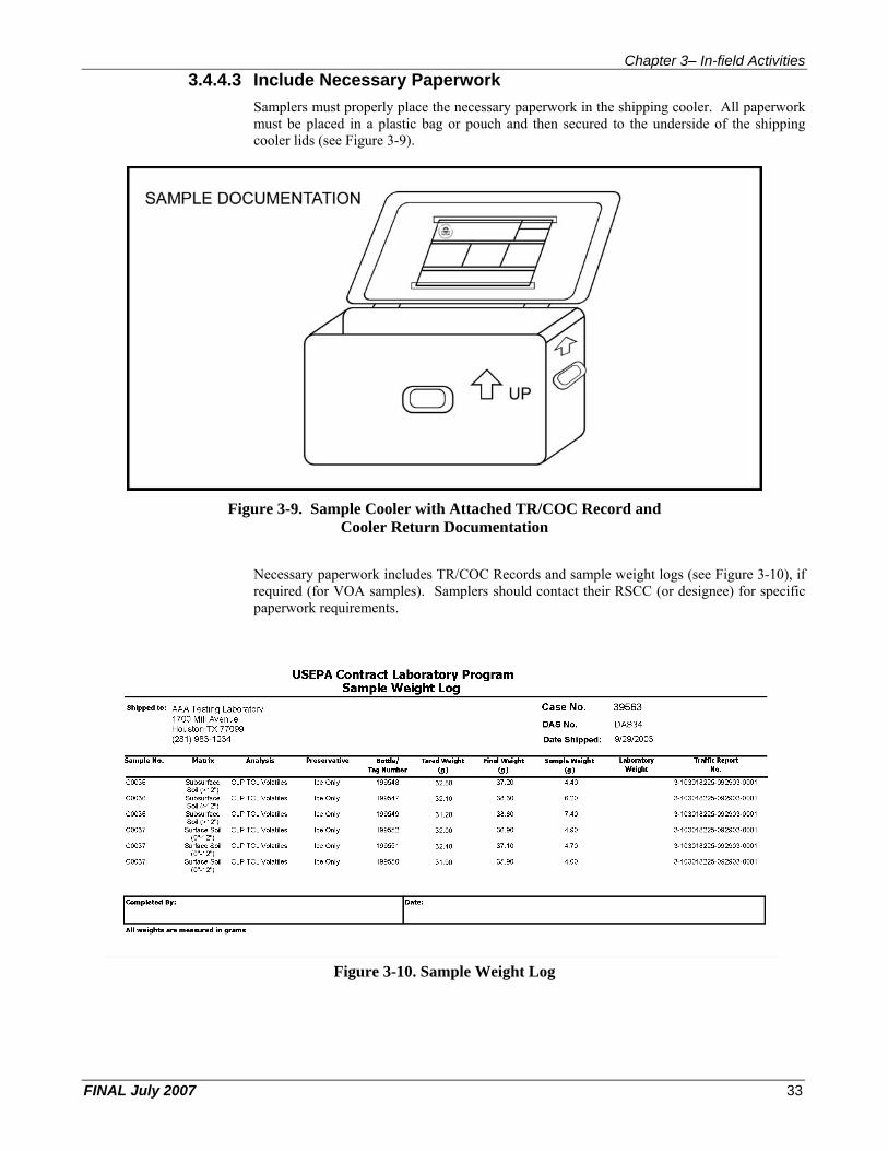
Chapter 3– In-field Activities 3.4.4.3 Include Necessary Paperwork
Samplers must properly place the necessary paperwork in the shipping cooler. All paperwork must be placed in a plastic bag or pouch and then secured to the underside of the shipping cooler lids (see Figure 3-9).
Figure 3-9. Sample Cooler with Attached TR/COC Record and Cooler Return Documentation
Necessary paperwork includes TR/COC Records and sample weight logs (see Figure 3-10), if required (for VOA samples). Samplers should contact their RSCC (or designee) for specific paperwork requirements.
Figure 3-10. Sample Weight Log
FINAL July 2007 33
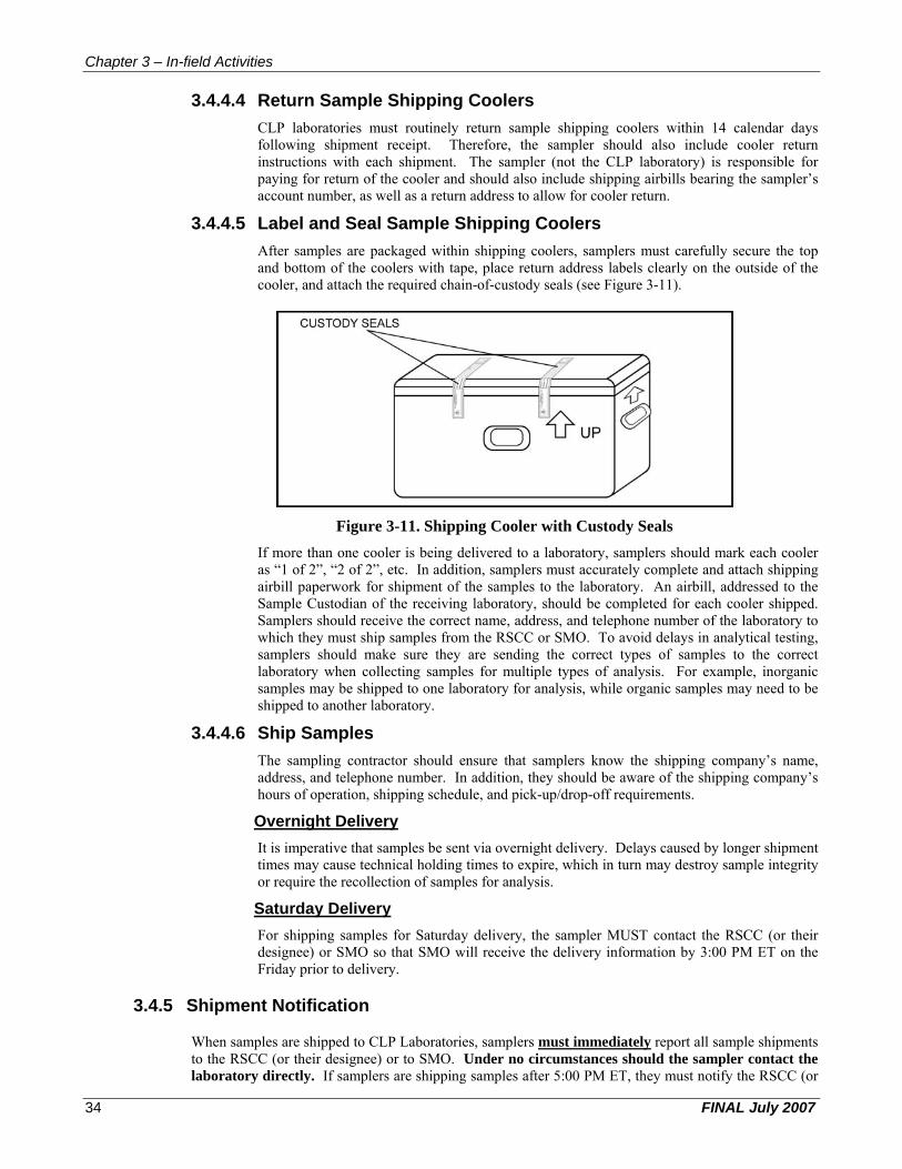
Chapter 3 – In-field Activities
3.4.4.4 Return Sample Shipping Coolers CLP laboratories must routinely return sample shipping coolers within 14 calendar days following shipment receipt. Therefore, the sampler should also include cooler return instructions with each shipment. The sampler (not the CLP laboratory) is responsible for paying for return of the cooler and should also include shipping airbills bearing the sampler’s account number, as well as a return address to allow for cooler return.
3.4.4.5 Label and Seal Sample Shipping Coolers After samples are packaged within shipping coolers, samplers must carefully secure the top and bottom of the coolers with tape, place return address labels clearly on the outside of the cooler, and attach the required chain-of-custody seals (see Figure 3-11).
Figure 3-11. Shipping Cooler with Custody Seals
If more than one cooler is being delivered to a laboratory, samplers should mark each cooler as “1 of 2”, “2 of 2”, etc. In addition, samplers must accurately complete and attach shipping airbill paperwork for shipment of the samples to the laboratory. An airbill, addressed to the Sample Custodian of the receiving laboratory, should be completed for each cooler shipped. Samplers should receive the correct name, address, and telephone number of the laboratory to which they must ship samples from the RSCC or SMO. To avoid delays in analytical testing, samplers should make sure they are sending the correct types of samples to the correct laboratory when collecting samples for multiple types of analysis. For example, inorganic samples may be shipped to one laboratory for analysis, while organic samples may need to be shipped to another laboratory.
3.4.4.6 Ship Samples The sampling contractor should ensure that samplers know the shipping company’s name, address, and telephone number. In addition, they should be aware of the shipping company’s hours of operation, shipping schedule, and pick-up/drop-off requirements.
Overnight Delivery
It is imperative that samples be sent via overnight delivery. Delays caused by longer shipment times may cause technical holding times to expire, which in turn may destroy sample integrity or require the recollection of samples for analysis.
Saturday Delivery
For shipping samples for Saturday delivery, the sampler MUST contact the RSCC (or their designee) or SMO so that SMO will receive the delivery information by 3:00 PM ET on the Friday prior to delivery.
3.4.5 Shipment Notification
When samples are shipped to CLP Laboratories, samplers must immediately report all sample shipments to the RSCC (or their designee) or to SMO. Under no circumstances should the sampler contact the laboratory directly. If samplers are shipping samples after 5:00 PM ET, they must notify the RSCC (or
FINAL July 2007 34
Chapter 3– In-field Activities designee) or SMO by 8:00 AM ET on the following business day. Samplers should receive the name and phone number of the appropriate SMO coordinator to contact from the Region/RSCC.
Samplers must provide the following information to the RSCC (or their designee) or to SMO:
• Name and phone number at which they can easily be reached (preferably closest on-site phone number if still in the field);
• SMO-assigned Case Number (see Section 2.4.1); • Number, concentration, matrix and analysis of samples being shipped; • Name of laboratory (or laboratories) to which the samples were shipped; • Airbill number(s); • Date of shipment; • Case status (i.e., whether or not the Case is complete); • Problems encountered, special comments, or any unanticipated issues; • When to expect the next anticipated shipment; and • An electronic export of the TR/COC Record (must be sent as soon as possible after sample
shipment). For information regarding electronic export of TR/COC Records, refer to the following Web site:
http://www.epa.gov/superfund/programs/clp/f2lsubmit.htm
For Saturday delivery, samplers MUST contact the RSCC (or their designee) or SMO so that SMO will receive the delivery information by 3:00 PM ET on the Friday prior to delivery.
Samplers should be aware if their Region requires them to notify the RSCC (or designee) and/or SMO of sample shipment.
FINAL July 2007 35
Chapter 3 – In-field Activities
THIS PAGE INTENTIONALLY LEFT BLANK
FINAL July 2007 36

Appendix A
Appendix A: Functions within a Sampling Project
The following table describes Quality Assurance Project Plan (QAPP) requirements taken from EPA Requirements for Quality Assurance Project Plans (EPA QA/R-5).
Functions Within a Sampling Project Elements of that Function
Project Management
Project/Task Organization Identifies the individuals or organizations participating in the project and defines their specific roles and responsibilities.
Problem Definition/Background States the specific problem to be solved or decision to be made and includes sufficient background information to provide a historical and scientific perspective for each particular project.
Project/Task Description
Describes the work to be performed and the schedule for implementation to include: C Measurements to be made during the course of the project; C Applicable technical, regulatory, or program-specific quality standards, criteria, or
objectives; C Any special personnel and equipment requirements; assessment tools needed; and C A work schedule and any required project and quality records, including types of reports
needed.
Quality Objectives and Criteria Describes the project quality objectives and measurement performance criteria.
Special Training/Certification Ensures that any specialized training for non-routine field sampling techniques, field analyses, laboratory analyses, or data validation should be specified.
Documents and Records
C Itemizes the information and records that must be included in the data report package and specifies the desired reporting format for hard copy and electronic forms, when used.
C Identifies any other records and/or documents applicable to the project such as audit reports, interim progress reports, and final reports that will be produced.
C Specifies or references all applicable requirements for the final disposition of records and documents, including location and length of retention period.
Data Generation and Acquisition
Sampling Process Design (Experimental Design)
C Describes the experimental design or data collection design for the project. C Classifies all measurements as critical or non-critical.
Sampling Methods
C Describes the procedures for collecting samples and identifies sampling methods and equipment. Includes any implementation requirements, support facilities, sample preservation requirements, and materials needed.
C Describes the process for preparing and decontaminating sampling equipment to include the disposal of decontamination by-products, selection and preparation of sample containers, sample volumes, preservation methods, and maximum holding times for sampling, preparation, and/or analysis.
C Describes specific performance requirements for the method. C Addresses what to do when a failure in sampling occurs, who is responsible for corrective
action, and how the effectiveness of the corrective action shall be determined and documented
Sample Handling and Custody
C Describes the requirements and provisions for sample handling and custody in the field, laboratory, and transport, taking into account the nature of the samples, the maximum allowable sample holding times before extraction and analysis, and the available shipping options and schedules.
C Includes examples of sample labels, custody forms, and sample custody logs.
FINAL July 2007 A-1

Appendix A
Analytical Methods
C
C
C
C
C
Identifies the analytical methods and equipment required, including sub-sampling or extraction methods, waste disposal requirements (if any), and specific method performance requirements. Identifies analytical methods by number, date, and regulatory citation (as appropriate). If a method allows the user to select from various options, the method citations should state exactly which options are being selected. Addresses what to do when a failure in the analytical system occurs, who is responsible for corrective action, and how the effectiveness of the corrective action shall be determined and documented. Specifies the laboratory turnaround time needed, if important to the project schedule. Specifies whether a field sampling and/or laboratory analysis Case Narrative is required to provide a complete description of any difficulties encountered during sampling or analysis.
Quality Control (QC)
C
C
C
C
Identifies required measurement QC checks for both the field and laboratory. States the frequency of analysis for each type of QC check, and the spike compounds sources and levels. States or references the required control limits for each QC check and corrective action required when control limits are exceeded and how the effectiveness of the corrective action shall be determined and documented. Describes or references the procedures to be used to calculate each of the QC statistics.
Instrument/Equipment Testing, Inspection, and Maintenance
C
C
C
C
C
Describes how inspections and acceptance testing of environmental sampling and measurement systems and their components will be performed and documented. Identifies and discusses the procedure by which final acceptance will be performed by independent personnel. Describes how deficiencies are to be resolved and when re-inspection will be performed. Describes or references how periodic preventative and corrective maintenance of measurement or test equipment shall be performed. Identifies the equipment and/or system requiring periodic maintenance. Discusses how the availability of spare parts identified in the operating guidance and/or design specifications of the systems will be assured and maintained.
Instrument/Equipment Calibration and Frequency
C
C
C
C
Identifies all tools, gauges, instruments, and other sampling, measuring, and test equipment used for data collection activities affecting quality that must be controlled, and at specific times, calibrated to maintain performance within specified limits. Identifies the certified equipment and/or standards used for calibration. Describes or references how calibration will be conducted using certified equipment and/or standards with known valid relationships to nationally recognized performance standards. If no such standards exist, documents the basis for calibration. Indicates how records of calibration shall be maintained and traced to the instrument.
Inspection/Acceptance of Supplies and Consumables
C
C
Describes how and by whom supplies and consumables shall be inspected and accepted for use in the project. States acceptance criteria for such supplies and consumables.
Non-direct Measurements
C
C
C
C
Identifies any types of data needed for project implementation or decision-making that are obtained from non-measurement sources (e.g., computer databases, programs, literature files, historical databases). Describes the intended use of data. Defines the acceptance criteria for the use of such data in the project. Specifies any limitations on the use of the data.
Data Management
C
C
Describes the project data management scheme, tracing the data path from generation in the field or laboratory to their final use or storage. Describes or references the standard record-keeping procedures, document control system, and the approach used for data storage and retrieval on electronic media.
FINAL July 2007 A-2
Appendix B
Appendix B: CLP Sample Collection Guidelines for VOAs in Soil by SW-846 Method 5035A
A. Preferred Options for the Contract Laboratory Program (CLP) are Options 1, 2, and 3:
Soil samples must be placed on their sides prior to being frozen.
Option 1.
Closed-system Vials: Container - tared or preweighed 40 mL VOA Vials containing a magnetic stir bar.
Collect 5 g of soil per vial (iced or frozen in the field). Regular Samples 3 Vials - Dry (5 g soil per vial)
1 Vial - Dry (filled with soil, no headspace) 4 Total Vials
Regular Samples 9 Vials - Dry (5 g soil per vial) Requiring QC Analysis 1 Vial - Dry (filled with soil, no headspace)
10 Total Vials
Option 2.
Closed-system Vials Containing Water: Container - tared or pre-weighed 40 mL VOA vials containing a magnetic stir bar and 5 mL water.
Collect 5 g of soil per vial (iced or frozen in the field).
Regular Samples 2 Vials with water added (5 g soil and 5 mL water per vial) 1 Vial - Dry (5 g soil in vial) 1 Vial - Dry (filled with soil, no headspace) 4 Total Vials (2 with water and 2 dry)
Regular Samples 6 Vials with water added (5 g soil and 5 mL water per vial) Requiring QC Analysis 5 Vials - Dry (5 g soil per vial)
1 Vial - Dry (filled with soil, no headspace) 12 Total Vials (6 with water and 6 dry)
Option 3.
Coring Tool used as a Transport Device Container - 5 g Samplers or equivalent.
All Samplers should be iced or frozen in the field and bagged individually.
Regular Samples 3 Samplers (5 g soil per Sampler) 1 Vial - Dry (filled with soil, no headspace) 4 Total (3 Samplers and 1 Vial)
Regular Samples 9 Samplers (5 g soil per Sampler) Requiring QC Analysis 1 Vial - Dry (filled with soil, no headspace)
10 Total (11 Samplers and 1 Vial)
FINAL July 2007 B-1

Appendix B
B. Options 4, 5, and 6 are NOT preferred options for the CLP:
Option 4.
Closed-system Vials: Container - tared or preweighed 40 mL VOA Vials containing a magnetic stir bar and preservative.
Collect 5 g of soil per vial and add Sodium bisulfate (NaHSO4) preservative (5 mL water + 1 g NaHSO4) iced or frozen in the field.
Caution: This option is NOT a Preferred Option for the CLP because:
NaHSO4 preservation creates low pH conditions that will cause the destruction of certain CLP target analytes (e.g., vinyl chloride, trichloroethene, trichlorofluoromethane, cis- and trans1,3-dichloropropene). Projects requiring the quantitation of these analytes should consider alternative sample preservation methods. NaHSO4 also cannot be used on carbonaceous soils. Check the soil before using this method of collection! Soil can be checked by placing a test sample in a clean vial, then adding several drops of NaHSO4 solution. If the soil bubbles, use Option 4b and note this issue on the TR/COC Record.
Option 4a. Samples preserved in the field
Regular Samples 2 Vials with NaHSO4 preservative added (5g soil per vial) 1 Vial without NaHSO4 preservative added (5g soil per vial) 1 Vial - Dry (filled with soil, no headspace) 4 Total Vials (2 with NaHSO4 preservative and 2 without)
Regular Samples 4 Vials with NaHSO4 preservative added (5g soil per vial) Requiring QC Analyses 5 Vials without NaHSO4 preservative added (5 g soil per vial)
1 Vial - Dry (filled with soil, no headspace) 10 Total Vials (4 with NaHSO4 and 6 without)
Option 4b. Samples are preserved by the laboratory (No NaHSO4 preservative is added to these samples in the field).
Regular Samples 3 Vials - Dry (5 g soil per vial) 1 Vial - Dry (filled with soil, no headspace) 4 Total Vials
Regular Samples 9 Vials - Dry (5 g soil per vial) Requiring QC Analyses 1 Vial - Dry (filled with soil, no headspace)
10 Total Vials
Option 5.
Methanol Preservation (medium-level analysis only): Container - tared or pre-weighed 40 mL VOA vials containing 5-10 mL methanol.
Collect 5 g of soil per vial (iced in the field).
FINAL July 2007 B-2
Appendix B
Caution: This is NOT a preferred option for the CLP because:
Samples preserved with methanol can only be analyzed by the medium-level method. Low-level Contract Required Quantitation Limit (CRQLs) cannot be achieved when samples are preserved this way.
Additional problems associated with use of methanol as a preservative in the field include:
• Possible contamination of the methanol by sampling-related activities (e.g., absorption of diesel fumes from sampling equipment);
• Leakage of methanol from the sample vials during shipping, resulting in loss of VOAs prior to analysis.
Regular Samples 2 Vials (5 g soil and 5-10 mL methanol per vial) 1 Vial - Dry (filled with soil, no headspace) 3 Total Vials (2 with methanol and 1 dry)
Regular Samples 6 Vials (5 g soil and 5-10 mL methanol per vial) Requiring QC Analysis 1 Vial -Dry (filled with soil, no headspace)
7 Total Vials (6 with methanol and 1 dry)
If shipping samples containing methanol as a preservative, a shipping label must be used to indicate methanol. This label must also contain the United Nations (UN) identification number for methanol (UN 1230), and indicate Limited Quantity.
Option 6.
Glass Containers filled with sample - No Headspace: Container - 4 oz Glass Jars.
Glass container filled with soil with no headspace and iced.
Caution: This is NOT a preferred option for the CLP because:
Samples collected in this manner lose most of their volatile analytes prior to analysis when the sample containers are opened and sub-sampled in the laboratory. This option is only available due to Regional requirements.
Regular Samples 2 Glass Jars (4 oz) filled with sample, no headspace 1 Vial - Dry (filled with soil, no headspace) 3 Total Containers
Regular Samples 2 Glass Jars (4 oz) filled with sample, no headspace Requiring QC Analysis 1 Vial - Dry (filled with soil, no headspace)
3 Total Containers
C. Caution:
1. Extreme care must be taken to ensure that frozen samples do not break during shipment.
2. Before adding soil to pre-weighed vials containing a stir bar, weigh the vials to confirm the tared weight. If the weight varies by more than 0.1 g, record the new weight on the label and the sample documentation. Do NOT add labels to these vials once the tared weight has been determined/confirmed.
FINAL July 2007 B-3

Appendix B
D. Dry Samples:
All options include taking a sample in a dry 40 mL VOA vial (or a 4 oz wide mouth jar) with no headspace. No additional water, NaHSO4, or methanol is added to this sample. This sample is taken to determine moisture content; therefore, it does not need to be tared or have a stir bar.
E. Iced or Frozen Samples:
1. Iced means cooled to 4°C (±2°C) immediately after collection.
2. Frozen means cooled to between -7°C and -15°C immediately after collection.
F. Sample Delivery:
CLP strongly recommends that all samples reach the laboratory by COB the next day after sample collection.
G. Notes:
1. For Option 4, samples can be preserved with NaHSO4 either:
• In the field; or • In the laboratory upon receipt. In this case, the sampler should put the following information in the
Preservation Column of the TR/COC Record - “To be preserved at lab with NaHSO4". This Regional Request should also be communicated to SMO so that the laboratory can be notified.
2. Regional QAPPs may require the use of Option 5. Please note that this option is for medium-level analysis ONLY.
3. If water, methanol, or NaHSO4 preservative is added to the vials in the field, a field blank containing the appropriate liquid used in the vials should be sent to the laboratory for analysis.
H. Number of Containers Rationale:
The rationale for the number of containers (vials or samplers) required for the field sample and the required laboratory QC for each option is given as follows:
Option 1.
Rationale for Regular 1 vial for low-level analysis (water purge) Vials: 1 vial for backup low-level analysis
1 vial for medium-level analysis (methanol extraction)
Rationale for QC 2 vials for MS and MSD low-level analysis Vials: 2 vials for MS and MSD medium-level analysis
2 vials for backup (MS and MSD) low-level or medium-level analysis
FINAL July 2007 B-4
Appendix B
Option 2.
Rationale for Regular 1 vial for low-level analysis (water purge) Vials: 1 vial for back up low-level analysis
1 vial dry for medium-level analysis (methanol extraction)
Rationale for QC 2 vials for MS and MSD low-level analysis Vials: 2 vials for MS and MSD medium-level analysis
2 vials for backup (MS and MSD) low-level or medium-level analysis
Medium-level: Methanol will be added in the laboratory Analysis
Option 3.
Rationale for Regular 1 sampler for low-level analysis (water purge) Samples: 1 sampler for back up low-level analysis
1 sampler for medium-level analysis (methanol extraction)
Rationale for QC 2 samplers for MS and MSD low-level analysis Samples: 2 samplers for backup MS and MSD low-level analysis
2 samplers for MS and MSD medium-level analysis 2 samplers for backup MS and MSD medium-level analysis
Option 4a (NaHSO4 added in the field).
Rationale for Regular 1 vial with water for low-level analysis (water purge) Vials: 1 vial with water for backup low-level analysis
1 vial dry for medium-level analysis (methanol extraction)
Rationale for QC 2 vials with water for MS and MSD low-level analysis Vials: 2 vials dry for MS and MSD medium-level analysis
2 vials for backup (MS and MSD) low-level or medium-level analysis
Option 4b (NaHSO4 added in the laboratory).
Rationale for Regular 1 vial for low-level analysis (water purge) Vials: 1 vial for backup low-level analysis
1 vial for medium-level analysis (methanol extraction)
Rationale for QC 2 vials for MS and MSD low-level analysis Vials: 2 vials for MS and MSD medium-level analysis
2 vials for backup (MS and MSD) low-level or medium-level analysis
Option 5.
Rationale for Regular 1 vial for regular medium-level analysis Samples: 1 vial for back up medium-level analysis
Rationale for QC 2 samples for MS and MSD Samples: 2 samples for backup MS and MSD
FINAL July 2007 B-5
Appendix B
Option 6.
In this option, all Regular and QC samples for both low-level and medium analysis are taken as subsamples from the same container.
Rationale for Regular 1 glass jar for low-level analysis and medium-level analysis Analysis 1 glass jar for backup low-level analysis and medium-level analysis
Rationale for 1 glass jar for low-level analysis and medium-level analysis QC Analysis: 1 glass jar for backup low-level analysis and medium-level analysis
FINAL July 2007 B-6
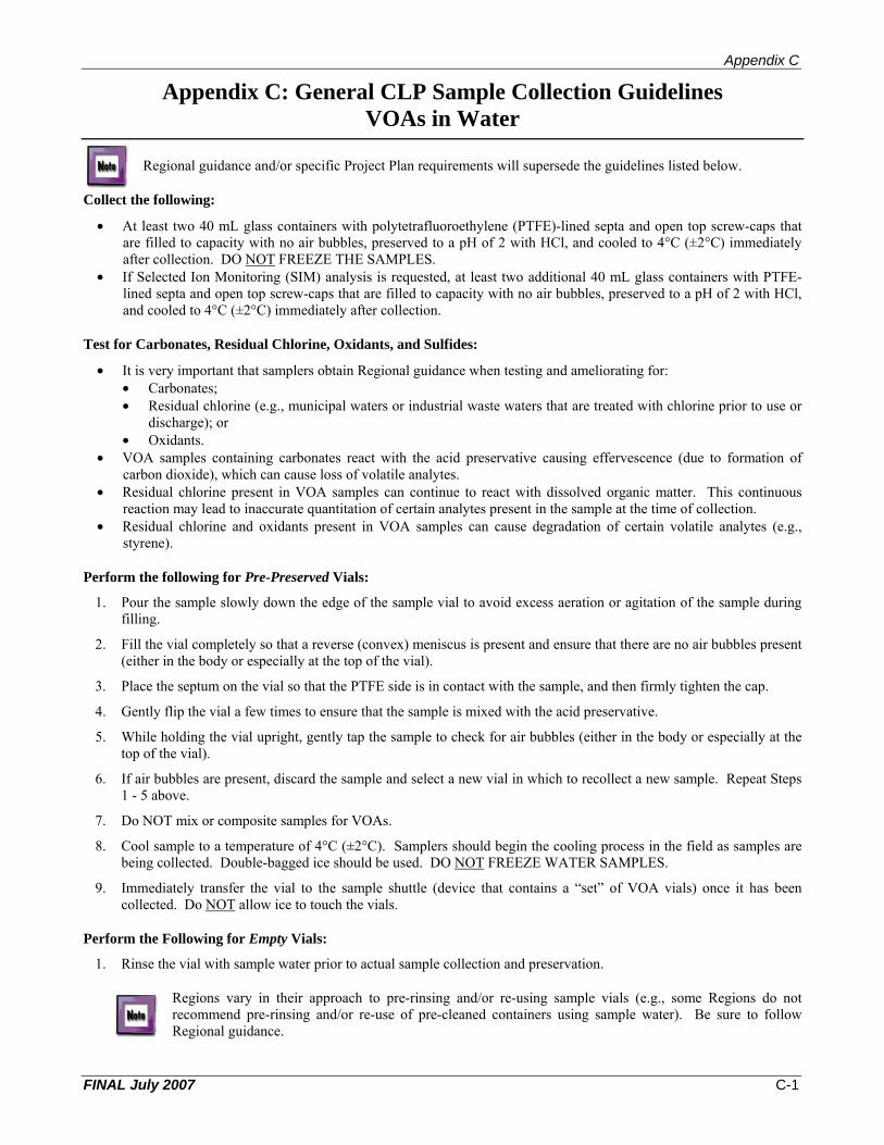
Appendix C
Appendix C: General CLP Sample Collection Guidelines VOAs in Water
Regional guidance and/or specific Project Plan requirements will supersede the guidelines listed below.
Collect the following:
• At least two 40 mL glass containers with polytetrafluoroethylene (PTFE)-lined septa and open top screw-caps that are filled to capacity with no air bubbles, preserved to a pH of 2 with HCl, and cooled to 4°C (±2°C) immediately after collection. DO NOT FREEZE THE SAMPLES.
• If Selected Ion Monitoring (SIM) analysis is requested, at least two additional 40 mL glass containers with PTFE-lined septa and open top screw-caps that are filled to capacity with no air bubbles, preserved to a pH of 2 with HCl, and cooled to 4°C (±2°C) immediately after collection.
Test for Carbonates, Residual Chlorine, Oxidants, and Sulfides:
• It is very important that samplers obtain Regional guidance when testing and ameliorating for: • Carbonates; • Residual chlorine (e.g., municipal waters or industrial waste waters that are treated with chlorine prior to use or
discharge); or • Oxidants.
• VOA samples containing carbonates react with the acid preservative causing effervescence (due to formation of carbon dioxide), which can cause loss of volatile analytes.
• Residual chlorine present in VOA samples can continue to react with dissolved organic matter. This continuous reaction may lead to inaccurate quantitation of certain analytes present in the sample at the time of collection.
• Residual chlorine and oxidants present in VOA samples can cause degradation of certain volatile analytes (e.g., styrene).
Perform the following for Pre-Preserved Vials:
1. Pour the sample slowly down the edge of the sample vial to avoid excess aeration or agitation of the sample during filling.
2. Fill the vial completely so that a reverse (convex) meniscus is present and ensure that there are no air bubbles present (either in the body or especially at the top of the vial).
3. Place the septum on the vial so that the PTFE side is in contact with the sample, and then firmly tighten the cap.
4. Gently flip the vial a few times to ensure that the sample is mixed with the acid preservative.
5. While holding the vial upright, gently tap the sample to check for air bubbles (either in the body or especially at the top of the vial).
6. If air bubbles are present, discard the sample and select a new vial in which to recollect a new sample. Repeat Steps 1 - 5 above.
7. Do NOT mix or composite samples for VOAs.
8. Cool sample to a temperature of 4°C (±2°C). Samplers should begin the cooling process in the field as samples are being collected. Double-bagged ice should be used. DO NOT FREEZE WATER SAMPLES.
9. Immediately transfer the vial to the sample shuttle (device that contains a “set” of VOA vials) once it has been collected. Do NOT allow ice to touch the vials.
Perform the Following for Empty Vials:
1. Rinse the vial with sample water prior to actual sample collection and preservation.
Regions vary in their approach to pre-rinsing and/or re-using sample vials (e.g., some Regions do not recommend pre-rinsing and/or re-use of pre-cleaned containers using sample water). Be sure to follow Regional guidance.
FINAL July 2007 C-1
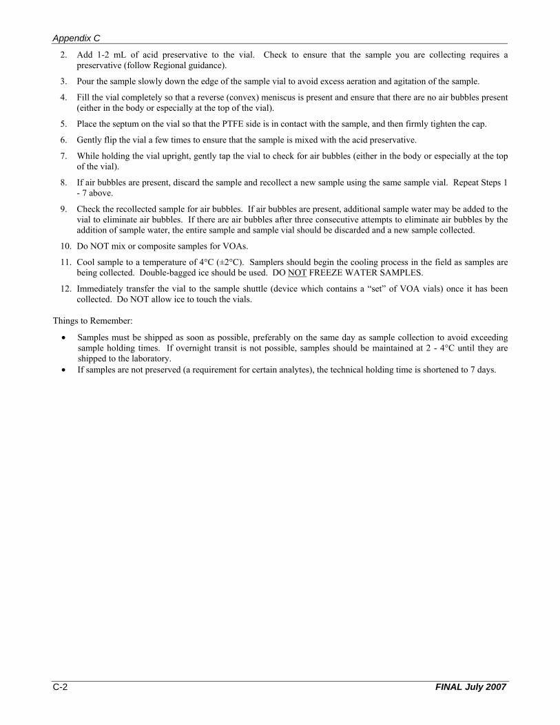
Appendix C
2. Add 1-2 mL of acid preservative to the vial. Check to ensure that the sample you are collecting requires a preservative (follow Regional guidance).
3. Pour the sample slowly down the edge of the sample vial to avoid excess aeration and agitation of the sample.
4. Fill the vial completely so that a reverse (convex) meniscus is present and ensure that there are no air bubbles present (either in the body or especially at the top of the vial).
5. Place the septum on the vial so that the PTFE side is in contact with the sample, and then firmly tighten the cap.
6. Gently flip the vial a few times to ensure that the sample is mixed with the acid preservative.
7. While holding the vial upright, gently tap the vial to check for air bubbles (either in the body or especially at the top of the vial).
8. If air bubbles are present, discard the sample and recollect a new sample using the same sample vial. Repeat Steps 1 - 7 above.
9. Check the recollected sample for air bubbles. If air bubbles are present, additional sample water may be added to the vial to eliminate air bubbles. If there are air bubbles after three consecutive attempts to eliminate air bubbles by the addition of sample water, the entire sample and sample vial should be discarded and a new sample collected.
10. Do NOT mix or composite samples for VOAs.
11. Cool sample to a temperature of 4°C (±2°C). Samplers should begin the cooling process in the field as samples are being collected. Double-bagged ice should be used. DO NOT FREEZE WATER SAMPLES.
12. Immediately transfer the vial to the sample shuttle (device which contains a “set” of VOA vials) once it has been collected. Do NOT allow ice to touch the vials.
Things to Remember:
• Samples must be shipped as soon as possible, preferably on the same day as sample collection to avoid exceeding sample holding times. If overnight transit is not possible, samples should be maintained at 2 - 4°C until they are shipped to the laboratory.
• If samples are not preserved (a requirement for certain analytes), the technical holding time is shortened to 7 days.
FINAL July 2007 C-2
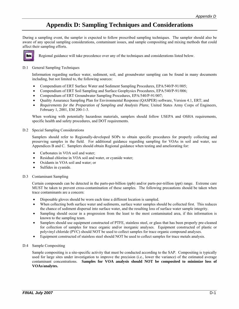
Appendix D
Appendix D: Sampling Techniques and Considerations
affect their sampling efforts.
During a sampling event, the sampler is expected to follow prescribed sampling techniques. The sampler should also be aware of any special sampling considerations, contaminant issues, and sample compositing and mixing methods that could
Regional guidance will take precedence over any of the techniques and considerations listed below.
D.1 General Sampling Techniques
Information regarding surface water, sediment, soil, and groundwater sampling can be found in many documents including, but not limited to, the following sources:
• Compendium of ERT Surface Water and Sediment Sampling Procedures, EPA/540/P-91/005; • Compendium of ERT Soil Sampling and Surface Geophysics Procedures, EPA/540/P-91/006; • Compendium of ERT Groundwater Sampling Procedures, EPA/540/P-91/007; • Quality Assurance Sampling Plan for Environmental Response (QASPER) software, Version 4.1, ERT; and • Requirements for the Preparation of Sampling and Analysis Plans; United States Army Corps of Engineers,
February 1, 2001, EM 200-1-3.
When working with potentially hazardous materials, samplers should follow USEPA and OSHA requirements, specific health and safety procedures, and DOT requirements.
D.2 Special Sampling Considerations
Samplers should refer to Regionally-developed SOPs to obtain specific procedures for properly collecting and preserving samples in the field. For additional guidance regarding sampling for VOAs in soil and water, see Appendices B and C. Samplers should obtain Regional guidance when testing and ameliorating for:
• Carbonates in VOA soil and water; • Residual chlorine in VOA soil and water, or cyanide water; • Oxidants in VOA soil and water; or • Sulfides in cyanide.
D.3 Contaminant Sampling
Certain compounds can be detected in the parts-per-billion (ppb) and/or parts-per-trillion (ppt) range. Extreme care MUST be taken to prevent cross-contamination of these samples. The following precautions should be taken when trace contaminants are a concern:
• Disposable gloves should be worn each time a different location is sampled. • When collecting both surface water and sediments, surface water samples should be collected first. This reduces
the chance of sediment dispersal into surface water, and the resulting loss of surface water sample integrity. • Sampling should occur in a progression from the least to the most contaminated area, if this information is
known to the sampling team. • Samplers should use equipment constructed of PTFE, stainless steel, or glass that has been properly pre-cleaned
for collection of samples for trace organic and/or inorganic analyses. Equipment constructed of plastic or polyvinyl chloride (PVC) should NOT be used to collect samples for trace organic compound analyses.
• Equipment constructed of stainless steel should NOT be used to collect samples for trace metals analysis.
D.4 Sample Compositing
Sample compositing is a site-specific activity that must be conducted according to the SAP. Compositing is typically used for large sites under investigation to improve the precision (i.e., lower the variance) of the estimated average contaminant concentrations. Samples for VOA analysis should NOT be composited to minimize loss of VOAs/analytes.
FINAL July 2007 D-1

Appendix D
Composite samples consist of a series of discrete grab samples that are mixed together to characterize the average composition of a given material. The discrete samples are usually of equal volume, but may be weighted to reflect an increased flow or volume. Regardless, all discrete samples must be collected in an identical manner and the number of grab samples forming a composite should be consistent. There are several compositing techniques that may be required such as:
• Flow-proportioned – Collected proportional to the flow rate during the compositing period by either a time-varying/constant volume or a time-constant/varying volume method. This technique is usually associated with wastewater or storm water runoff sampling.
• Time – Composed of a varying number of discrete samples collected at equal time intervals during the compositing period. This technique is typically used to sample wastewater and streams, and in some air sampling applications.
• Areal – Collected from individual grab samples collected in an area or on a cross-sectional basis. Areal composites are comprised of equal volumes of grab samples where all grabs are collected in an identical manner. This technique is typically used for estimating average contaminant concentrations in soils or sediments. This technique is useful when contaminants are present in nugget form (i.e., TNT chunks, lead shot, etc.), thus exhibiting large differences in concentration over a small sample area.
• Vertical – Collected from individual grab samples but taken from a vertical cross section. Vertical composites are comprised of equal volumes of grab samples where all grab samples are collected in an identical manner. Examples would include vertical profiles of a soil borehole or sediment columns.
• Volume – Collected from discrete samples whose aliquot volumes are proportional to the volume of sampled material. Volume composites are usually associated with hazardous waste bulking operations where the sample represents combined or bulked waste.
When compositing solid samples (i.e., sediment, soil, or sludge) for analysis of compounds present in trace quantities, use a stainless steel or PTFE bowl and spatula.
D.5 Sample Mixing and Homogenizing
Mixing of the sample for the remaining parameters is necessary to create a representative sample media. It is extremely important that solid samples be mixed as thoroughly as possible to ensure that the sample is as representative as possible of the sample location. Please refer to the project-specific SAP regarding instructions on removal of any extraneous materials (e.g., leaves, sticks, rocks, etc.). The mixing technique will depend on the physical characteristics of the solid material (e.g., particle size, moisture content, etc.). The mixing container should be large enough to hold the sample volume and accommodate the procedures without spilling. Both the mixing container (generally a bowl or tray) and the mixing implement should be properly decontaminated before use. Samples should be homogenized according to procedures listed in the project-specific SAP.
Samples for VOA analysis should not be mixed to minimize loss of volatile analytes.
Table D-1 provides a short procedure for mixing a soil sample with a small particle size (less than 1/4 in) and filling sample containers in the field.
Table D-1. Mixing a Sample and Filling Sample Containers Step Action
1 Roll the contents of the compositing container to the middle of the container and mix.
2 Quarter the sample and move to the sides of the container.
3 Mix each quarter individually, then combine and mix OPPOSITE quarters, then roll to the middle of the container.
4 Mix the sample once more, and then quarter the sample again.
5 Mix each quarter individually, then combine and mix ADJACENT corners, then roll to the middle of the container. The goal is to achieve a consistent physical appearance before sample containers are filled.
6 Flatten piled material into an oblong shape.
7 Using a flat-bottomed scoop, collect a strip of soil across the entire width of the short axis and place it into a sample container.
8 Repeat Step 7 at evenly-spaced intervals until the sample containers are filled.
9 Record the approximate quantity of each subsample in the field log book.
FINAL July 2007 D-2
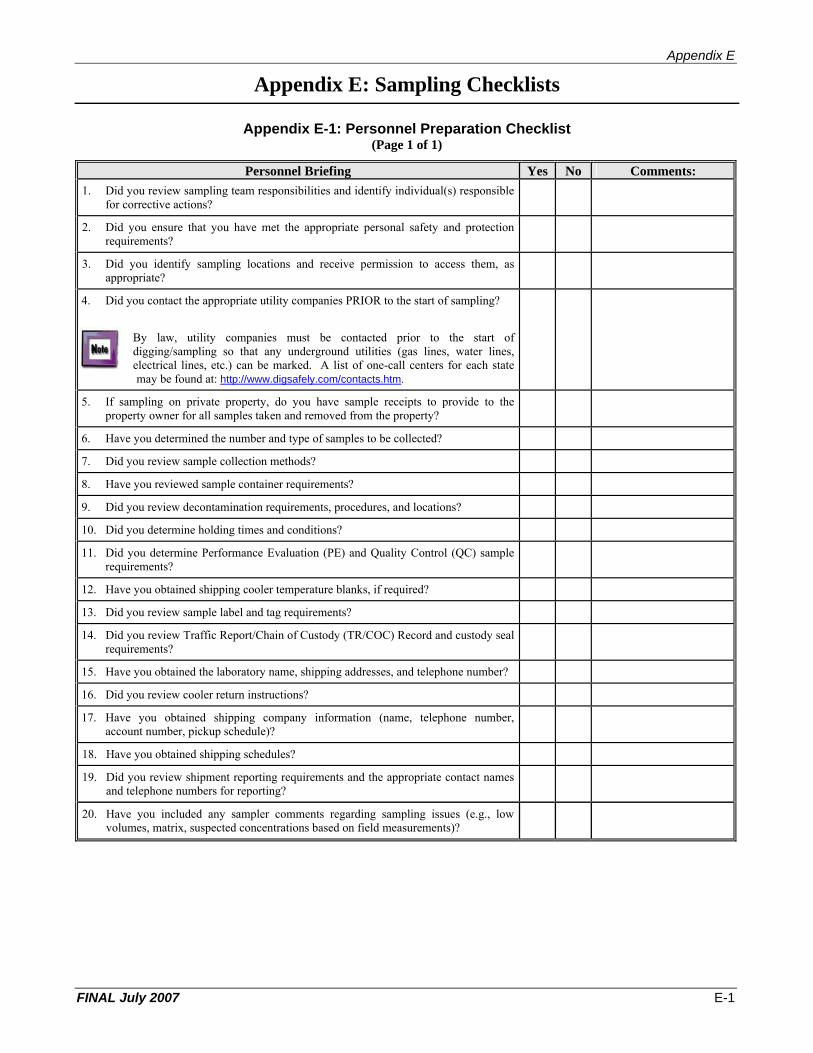
Appendix E
Appendix E: Sampling Checklists
Appendix E-1: Personnel Preparation Checklist (Page 1 of 1)
Personnel Briefing Yes No Comments: 1. Did you review sampling team responsibilities and identify individual(s) responsible
for corrective actions?
2. Did you ensure that you have met the appropriate personal safety and protection requirements?
3. Did you identify sampling locations and receive permission to access them, as appropriate?
4. Did you contact the appropriate utility companies PRIOR to the start of sampling?
By law, utility companies must be contacted prior to the start of digging/sampling so that any underground utilities (gas lines, water lines, electrical lines, etc.) can be marked. A list of one-call centers for each state may be found at: http://www.digsafely.com/contacts.htm.
5. If sampling on private property, do you have sample receipts to provide to the property owner for all samples taken and removed from the property?
6. Have you determined the number and type of samples to be collected?
7. Did you review sample collection methods?
8. Have you reviewed sample container requirements?
9. Did you review decontamination requirements, procedures, and locations?
10. Did you determine holding times and conditions?
11. Did you determine Performance Evaluation (PE) and Quality Control (QC) sample requirements?
12. Have you obtained shipping cooler temperature blanks, if required?
13. Did you review sample label and tag requirements?
14. Did you review Traffic Report/Chain of Custody (TR/COC) Record and custody seal requirements?
15. Have you obtained the laboratory name, shipping addresses, and telephone number?
16. Did you review cooler return instructions?
17. Have you obtained shipping company information (name, telephone number, account number, pickup schedule)?
18. Have you obtained shipping schedules?
19. Did you review shipment reporting requirements and the appropriate contact names and telephone numbers for reporting?
20. Have you included any sampler comments regarding sampling issues (e.g., low volumes, matrix, suspected concentrations based on field measurements)?
FINAL July 2007 E-1
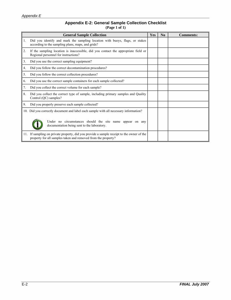
Appendix E
Appendix E-2: General Sample Collection Checklist (Page 1 of 1)
General Sample Collection Yes No Comments: 1. Did you identify and mark the sampling location with buoys, flags, or stakes
according to the sampling plans, maps, and grids?
2. If the sampling location is inaccessible, did you contact the appropriate field or Regional personnel for instructions?
3. Did you use the correct sampling equipment?
4. Did you follow the correct decontamination procedures?
5. Did you follow the correct collection procedures?
6. Did you use the correct sample containers for each sample collected?
7. Did you collect the correct volume for each sample?
8. Did you collect the correct type of sample, including primary samples and Quality Control (QC) samples?
9. Did you properly preserve each sample collected?
10. Did you correctly document and label each sample with all necessary information?
Under no circumstances should the site name appear on any documentation being sent to the laboratory.
11. If sampling on private property, did you provide a sample receipt to the owner of the property for all samples taken and removed from the property?
FINAL July 2007 E-2

Appendix E
Appendix E-3: Completing Field Logbook Checklist(Page 1 of 1)
Completing Field Logbook Yes No Comments: 1. Did you use waterproof ink when writing in the field logbook?
2. Did you document sampling project information such as: C Project name, ID, and location; C Names of samplers; C Geological observations, including maps; C Atmospheric conditions; C Field measurements; and C Sampling dates, times, and locations?
Under no circumstances should the site name appear on any documentation being sent to the laboratory.
3. Did you record sampling activity information such as: C Sampling dates and times; C Sample identifications; C Sample matrices; C Sample descriptions (e.g., odors and/or colors); C Number of samples taken; C Sampling methods/equipment; and C Description of QC samples?
4. Did you document any and all deviations from the sampling plan?
5. Did you document any and all difficulties in sampling and/or any unusual circumstances?
6. Were all errors corrected by crossing a line through the error, initialing the error, dating the error, and then adding the correct information?
FINAL July 2007 E-3

Appendix E
Appendix E-4: Completing Handwritten Sample Labels Checklist (Page 1 of 1)
Completing Handwritten Sample Labels Yes No Comments: 1. Did the Region provide CLP Sample Numbers and SMO-assigned Case Numbers?
2. If additional CLP Sample Numbers were needed, did you contact the appropriate Regional personnel?
3. Were the CLP Sample Numbers and SMO-assigned Case Numbers on the labels correct? Organic CLP Sample Numbers begin with the Regional letter code, followed by letters and numbers. Inorganic CLP Sample Numbers begin with “M”, followed by the Regional letter code, and then letters and numbers.
The following characters are not used in generating CLP Sample Numbers and should never appear on any paperwork send to the laboratory: I; O; U; and V. Also, the last character of a CLP Sample Number will never be a letter.
4. Were samples uniquely numbered and designated to only one sample?
Samples collected for total metal and dissolved metal analyses must receive separate, unique, CLP Sample Numbers.
5. Were Quality Control (QC) samples numbered accordingly?
6. Were the specific requirements followed for total and dissolved metals analysis, QC and Performance Evaluation (PE) samples, and SW-846 Method 5035A?
7. Were all temperature blanks labeled with “TEMPERATURE BLANK”?
8. Was a sample label containing the CLP Sample Number, SMO-assigned Case Number, location, concentration, preservative, and the fraction/analysis, attached to each sample bottle or container as the sample was collected?
Under no circumstances should the site name appear on any documentation being sent to the laboratory.
9. Was clear tape placed over the sample labels to protect the labels from moisture and to help the labels adhere to the sample bottle?
10. Were all errors corrected by crossing a line through the error, initialing the error, dating the error, and then adding the correct information?
FINAL July 2007 E-4

Appendix E
Appendix E-5: Completing Handwritten Sample Tags & Custody Seals Checklists (Page 1 of 1)
Completing Handwritten Sample Tags Yes No Comments: 1. Was waterproof ink used on the sample tags?
2. If Regionally required for individual sample containers, was the project code on the sample tag completed?
3. Was the station number on the sample tag completed?
4 Was the date filled in using the format MM/DD/YYYY?
5. Was the time of sample collection indicated in military time format HH:MM?
6. Was the box checked indicating composite or grab sample?
7. Was the station location on the sample tag completed?
8. Did you indicate whether or not the sample was preserved by checking “yes” or “no?”
9. Was the appropriate analysis indicated on the sample tag?
10. Were the appropriate CLP Sample Number and SMO-assigned Case Number indicated and cross-referenced with the numbers on the sample label?
11. Did you sign the sample tags?
12 Did you attach the sample tag to the neck of the sample bottle with striang, stretch string, or wire (recommended method)?
Do NOT use wire to attach a sample tag to a metal sample.
13. Were all errors corrected by crossing a line through the error, initialing the error, dating the error, and then adding the correct information?
Completing Custody Seals Yes No Comments: 1. Did you sign and date the custody seal?
2. Did you attach a completed custody seal to the sample bottle, container, or plastic bag, placing the seal over the cap or lid of each sample bottle or container or on the bag opening such that it will be broken if the sample bottle, container, or bag is opened or tampered with?
3. As appropriate, did you attach the completed custody seal to the sample shipping container or cooler, placing the seal such that it will be broken if the container or cooler is opened or tampered with?
4. Were all errors corrected by crossing a line through the error, initialing the error, dating the error, and then adding the correct information?
FINAL July 2007 E-5
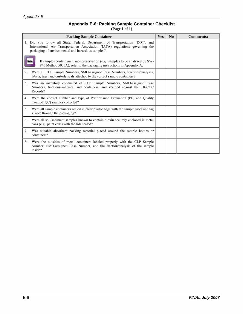
Appendix E
Appendix E-6: Packing Sample Container Checklist(Page 1 of 1)
Packing Sample Container Yes No Comments: 1. Did you follow all State, Federal, Department of Transportation (DOT), and
International Air Transportation Association (IATA) regulations governing the packaging of environmental and hazardous samples?
If samples contain methanol preservation (e.g., samples to be analyzed by SW846 Method 5035A), refer to the packaging instructions in Appendix A.
2. Were all CLP Sample Numbers, SMO-assigned Case Numbers, fractions/analyses, labels, tags, and custody seals attached to the correct sample containers?
3. Was an inventory conducted of CLP Sample Numbers, SMO-assigned Case Numbers, fractions/analyses, and containers, and verified against the TR/COC Records?
4. Were the correct number and type of Performance Evaluation (PE) and Quality Control (QC) samples collected?
5. Were all sample containers sealed in clear plastic bags with the sample label and tag visible through the packaging?
6. Were all soil/sediment samples known to contain dioxin securely enclosed in metal cans (e.g., paint cans) with the lids sealed?
7. Was suitable absorbent packing material placed around the sample bottles or containers?
8. Were the outsides of metal containers labeled properly with the CLP Sample Number, SMO-assigned Case Number, and the fraction/analysis of the sample inside?
FINAL July 2007 E-6

Appendix E
Appendix E-7: Packing Shipping Container Checklist(Page 1 of 1)
Packing Shipping Container Yes No Comments: 1. Were you shipping samples in a clean waterproof metal or hard plastic ice chest or
cooler in good condition?
2. Were all non-applicable labels from previous shipments removed from the container?
3. Were all inside and outside drain plugs closed and covered with suitable tape (e.g., duct tape)?
4. Was the inside of the cooler lined with plastic (e.g., large heavy-duty garbage bag)?
5. Was the lined shipping cooler packed with noncombustible absorbent packing material?
6. Were sample containers placed in the cooler in an upright position not touching one another?
7. Was a sample shipping cooler temperature blank included in the cooler?
8. Did the documentation in the cooler only address the samples in that cooler?
9. Was the site name absent from all documentation? Under no circumstances should the site name appear on any documentation being sent to the laboratory.
10. Was there sufficient packing material around and in between the sample bottles and cans to avoid breakage during transport?
11. If required, was double-bagged ice placed on top and around sample bottles to keep the samples cold at 4°C (± 2° C)?
Do Not Pack Loose Ice Into the Cooler!
12. Was the top of the plastic liner fastened and secured with tape?
13. Was a completed custody seal placed around the top of the fastened plastic liner (if required by the Region)?
14. Were all sample documents enclosed within the cooler (e.g., TR/COC Record and cooler return instructions) in a waterproof plastic bag?
15. Was the plastic bag, containing the documentation, taped to the underside of the cooler lid?
16. Were cooler return instructions and airbills, if required, taped to the underside of the cooler lid?
17. Was the return address of the cooler written with permanent ink on the underside of the cooler lid?
18. Was tape placed around the outside of the entire cooler and over the hinges?
19. Were the completed custody seals placed over the top edge of the cooler so the cooler cannot be opened without breaking the seals?
20. Was the return address label attached to the top left corner of the cooler lid?
21. Were instructional labels attached to the top of the cooler, as necessary (e.g., “This End Up,” “Do Not Tamper With,” or “Environmental Laboratory Samples”)?
22. If shipping hazardous samples, were the correct labels attached to the cooler (e.g., “Flammable Liquids”, “Caution”, or “Poison”)?
23. If shipping samples containing methanol as a preservative (e.g., samples to be analyzed by SW-846 Method 5035A), was a label used to indicate methanol, the United Nations (UN) identification number for methanol (UN 1230), and Limited Quantity?
FINAL July 2007 E-7

Appendix E
Appendix E-8: Shipping & Reporting CLP Samples Checklist (Page 1 of 1)
Shipping CLP Samples Yes No Comments: 1. Did you follow all State, Federal, Department of Transportation (DOT), and
International Air Transportation Association (IATA) regulations governing the shipment of environmental and hazardous samples?
2. Was a separate airbill filled out for each cooler being shipped?
3. Was the airbill filled out completely, including correct laboratory name, address, and telephone number, identification of recipient as “Sample Custodian,” and appropriate delivery option (e.g., overnight or Saturday)?
4. Was the completed airbill attached to the top of the cooler with the correct laboratory address?
5. If more than one cooler was being shipped to the same laboratory, were they marked as “1 of 2,” “2 of 2,” etc.?
6. Were the samples being shipped “overnight” through a qualified commercial carrier?
Reporting CLP Samples Yes No Comments: 1. Did you contact the Contract Laboratory Program Sample Management Office (SMO)
on the same day samples were shipped?
2. If the samples were shipped after 5:00 PM Eastern Time (ET), were they reported to the RSCC (or designee) or to SMO by 8:00 AM ET the following business day?
3. Did you notify the RSCC (or designee) or SMO so that SMO will receive the delivery information by 3:00 PM ET on Friday for sample shipments that will be delivered to the laboratory on Saturday?
4. Did you provide the RSCC (or designee) or SMO with: C Your name, phone number, and Region number; C Case Number of the project; C Exact number of samples, matrix(ces), concentration(s), and type of analysis; C Laboratory(ies) to which the samples were shipped; C Carrier name and airbill number; C Date of shipment; C Date of next shipment; and C Any other information pertinent to the shipment?
FINAL July 2007 E-8
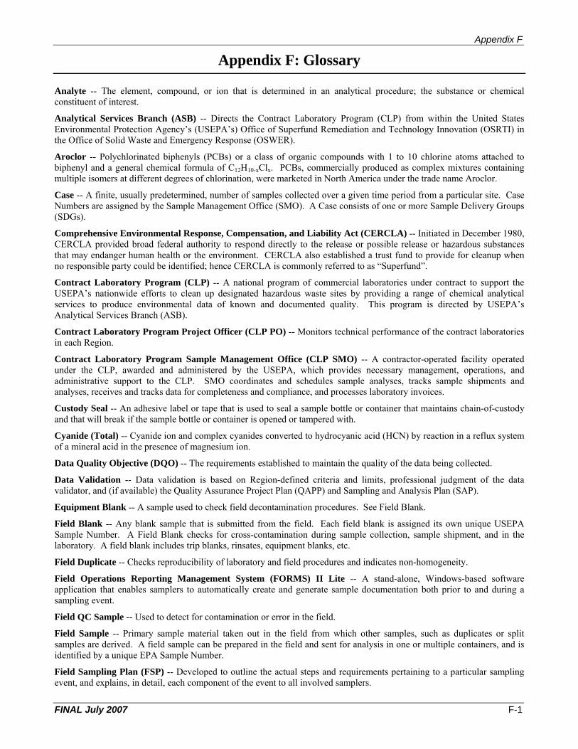
Appendix F
Appendix F: Glossary
Analyte -- The element, compound, or ion that is determined in an analytical procedure; the substance or chemical constituent of interest.
Analytical Services Branch (ASB) -- Directs the Contract Laboratory Program (CLP) from within the United States Environmental Protection Agency’s (USEPA’s) Office of Superfund Remediation and Technology Innovation (OSRTI) in the Office of Solid Waste and Emergency Response (OSWER).
Aroclor -- Polychlorinated biphenyls (PCBs) or a class of organic compounds with 1 to 10 chlorine atoms attached to biphenyl and a general chemical formula of C12H10-xClx. PCBs, commercially produced as complex mixtures containing multiple isomers at different degrees of chlorination, were marketed in North America under the trade name Aroclor.
Case -- A finite, usually predetermined, number of samples collected over a given time period from a particular site. Case Numbers are assigned by the Sample Management Office (SMO). A Case consists of one or more Sample Delivery Groups (SDGs).
Comprehensive Environmental Response, Compensation, and Liability Act (CERCLA) -- Initiated in December 1980, CERCLA provided broad federal authority to respond directly to the release or possible release or hazardous substances that may endanger human health or the environment. CERCLA also established a trust fund to provide for cleanup when no responsible party could be identified; hence CERCLA is commonly referred to as “Superfund”.
Contract Laboratory Program (CLP) -- A national program of commercial laboratories under contract to support the USEPA’s nationwide efforts to clean up designated hazardous waste sites by providing a range of chemical analytical services to produce environmental data of known and documented quality. This program is directed by USEPA’s Analytical Services Branch (ASB).
Contract Laboratory Program Project Officer (CLP PO) -- Monitors technical performance of the contract laboratories in each Region.
Contract Laboratory Program Sample Management Office (CLP SMO) -- A contractor-operated facility operated under the CLP, awarded and administered by the USEPA, which provides necessary management, operations, and administrative support to the CLP. SMO coordinates and schedules sample analyses, tracks sample shipments and analyses, receives and tracks data for completeness and compliance, and processes laboratory invoices.
Custody Seal -- An adhesive label or tape that is used to seal a sample bottle or container that maintains chain-of-custody and that will break if the sample bottle or container is opened or tampered with.
Cyanide (Total) -- Cyanide ion and complex cyanides converted to hydrocyanic acid (HCN) by reaction in a reflux system of a mineral acid in the presence of magnesium ion.
Data Quality Objective (DQO) -- The requirements established to maintain the quality of the data being collected.
Data Validation -- Data validation is based on Region-defined criteria and limits, professional judgment of the data validator, and (if available) the Quality Assurance Project Plan (QAPP) and Sampling and Analysis Plan (SAP).
Equipment Blank -- A sample used to check field decontamination procedures. See Field Blank.
Field Blank -- Any blank sample that is submitted from the field. Each field blank is assigned its own unique USEPA Sample Number. A Field Blank checks for cross-contamination during sample collection, sample shipment, and in the laboratory. A field blank includes trip blanks, rinsates, equipment blanks, etc.
Field Duplicate -- Checks reproducibility of laboratory and field procedures and indicates non-homogeneity.
Field Operations Reporting Management System (FORMS) II Lite -- A stand-alone, Windows-based software application that enables samplers to automatically create and generate sample documentation both prior to and during a sampling event.
Field QC Sample -- Used to detect for contamination or error in the field.
Field Sample -- Primary sample material taken out in the field from which other samples, such as duplicates or split samples are derived. A field sample can be prepared in the field and sent for analysis in one or multiple containers, and is identified by a unique EPA Sample Number.
Field Sampling Plan (FSP) -- Developed to outline the actual steps and requirements pertaining to a particular sampling event, and explains, in detail, each component of the event to all involved samplers.
FINAL July 2007 F-1

Appendix F
Holding Time -- The elapsed time expressed in hours, days, or months from the date of collection of the sample until the date of its analysis.
Contractual -- The lengths of time that the CLP laboratory must follow to comply with the terms of the contract, and are described in the CLP analytical services Statements of Work (SOWs).
Technical -- The maximum lengths of time that samples may be held from time of collection to time of preparation and/or analysis and still be considered valid.
Laboratory Blank -- See Method Blank.
Laboratory Duplicate -- A sample required by the laboratory’s contract to check the precision of inorganic analyses.
Laboratory QC Sample -- An additional volume of an existing sample, as required by the laboratory’s contract, used to detect contamination or error in the laboratory’s practices.
Matrix -- The predominant material of which a sample to be analyzed is composed.
Matrix Spike (MS) -- Sample required by the laboratory’s contract to check the accuracy of organic and inorganic analyses. It is an aliquot of a sample (water or soil) that is fortified (spiked) with known quantities of a specific compound and subjected to the entire analytical procedure. See Matrix Spike Duplicate.
Matrix Spike Duplicate (MSD) -- Sample required by the laboratory’s contract to check the accuracy and precision of organic analyses. It is a second aliquot of the same matrix as the Matrix Spike (MS) that is spiked to determine the precision of the method. See Matrix Spike.
Method Blank -- An analytical control consisting of all reagents, internal standards and surrogate standards [or System Monitoring Compounds (SMCs) for volatile organic analysis], that is carried throughout the entire analytical procedure. The method blank is used to define the level of laboratory, background, and reagent contamination, also referred to as laboratory blank when defining the level of laboratory contamination.
Performance Evaluation (PE) Sample -- A sample of known composition provided by the USEPA for contractor analysis. Used by USEPA to evaluate contractor performance.
Pesticides -- Substances intended to repel, kill, or control any species designated a “pest”, including weeds, insects, rodents, fungi, bacteria, and other organisms. Under the CLP, only organochlorine pesticides are analyzed (e.g., DDT, Dieldrin, Endrin, etc.).
Polychlorinated Biphenyls (PCBs) -- A group of toxic, persistent chemicals used in electrical transformers and capacitors for insulating purposes, and in gas pipeline systems as a lubricant. The sale and new use of PCBs were banned by law in 1979.
Quality Assurance (QA) -- An integrated system of management activities involving planning, implementation, assessment, reporting, and quality improvement to ensure that a process, item, or service is of the type and quality needed and expected by the customer.
Quality Assurance Project Plan (QAPP) -- Document written to meet requirements outlined in the document EPA Guidance for Quality Assurance Project Plans (EPA QA/R-5). Prepared in advance of field activities and used by samplers to develop any subsequent plans such as the Sampling Analysis Plan (SAP) or the Field Sampling Plan (FSP).
Quality Control (QC) -- The overall system of technical activities that measures the attributes and performance of a process, item, or service against defined standards to verify that they meet the stated requirements established by the customer; operational techniques and activities that are used to fulfill requirements for quality.
Regional Sample Control Center (RSCC) Coordinator -- In most Regions, coordinates sampling efforts and serves as the central point-of-contact for sampling questions and problems. Also assists in coordinating the level of Regional sampling activities to correspond with the monthly projected demand for analytical services.
Regional Site Manager -- Coordinates the development of data quality objectives and oversees project-specific remedial or removal contractors, State officials, or private parties conducting site sampling efforts.
Rinse Blank -- A sample used to check decontamination procedures. Also see Field Blank.
Routine Analytical Service (RAS) -- The standard inorganic and organic analyses available through the CLP.
Sample -- A discrete portion of material to be analyzed that is contained in single or multiple containers, and identified by a unique Sample Number.
FINAL July 2007 F-2
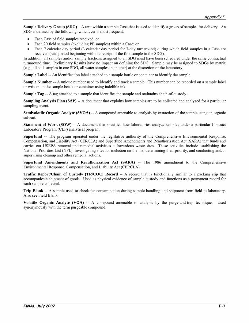
Appendix F
Sample Delivery Group (SDG) – A unit within a sample Case that is used to identify a group of samples for delivery. An SDG is defined by the following, whichever is most frequent:
• Each Case of field samples received; or • Each 20 field samples (excluding PE samples) within a Case; or • Each 7 calendar day period (3 calendar day period for 7-day turnaround) during which field samples in a Case are
received (said period beginning with the receipt of the first sample in the SDG). In addition, all samples and/or sample fractions assigned to an SDG must have been scheduled under the same contractual turnaround time. Preliminary Results have no impact on defining the SDG. Sample may be assigned to SDGs by matrix (e.g., all soil samples in one SDG, all water samples in another) at the discretion of the laboratory.
Sample Label -- An identification label attached to a sample bottle or container to identify the sample.
Sample Number -- A unique number used to identify and track a sample. This number can be recorded on a sample label or written on the sample bottle or container using indelible ink.
Sample Tag -- A tag attached to a sample that identifies the sample and maintains chain-of-custody.
Sampling Analysis Plan (SAP) -- A document that explains how samples are to be collected and analyzed for a particular sampling event.
Semivolatile Organic Analyte (SVOA) -- A compound amenable to analysis by extraction of the sample using an organic solvent.
Statement of Work (SOW) -- A document that specifies how laboratories analyze samples under a particular Contract Laboratory Program (CLP) analytical program.
Superfund -- The program operated under the legislative authority of the Comprehensive Environmental Response, Compensation, and Liability Act (CERCLA) and Superfund Amendments and Reauthorization Act (SARA) that funds and carries out USEPA removal and remedial activities at hazardous waste sites. These activities include establishing the National Priorities List (NPL), investigating sites for inclusion on the list, determining their priority, and conducting and/or supervising cleanup and other remedial actions.
Superfund Amendments and Reauthorization Act (SARA) -- The 1986 amendment to the Comprehensive Environmental Response, Compensation, and Liability Act (CERCLA).
Traffic Report/Chain of Custody (TR/COC) Record -- A record that is functionally similar to a packing slip that accompanies a shipment of goods. Used as physical evidence of sample custody and functions as a permanent record for each sample collected.
Trip Blank -- A sample used to check for contamination during sample handling and shipment from field to laboratory. Also see Field Blank.
Volatile Organic Analyte (VOA) -- A compound amenable to analysis by the purge-and-trap technique. Used synonymously with the term purgeable compound.
FINAL July 2007 F-3
Appendix F
THIS PAGE INTENTIONALLY LEFT BLANK
FINAL July 2007 F-4