review paper on microwave absorber using fss - ijser · review paper on microwave absorber using...
TRANSCRIPT

INTERNATIONAL JOURNAL OF SCIENTIFIC & ENGINEERING RESEARCH, VOLUME 6, ISSUE 10, OCTOBER-2015 ISSN 2229-5518
IJSER © 2015
http://www.IJSER.org
Review Paper on Microwave Absorber Using FSS
Pranati Sharma1
, Sanjeev Yadav2
M.Tech Student, ECE Department, Govt. Women Engg. College, Ajmer, India1
Assistant Professor, ECE Department, Govt. Women Engg. College, Ajmer, India2
Abstract: Microwave absorber are used in Military application, EMI reduction, Antenna pattern shaping, Radar cross reduction. Frequency-
selective surfaces have been most commonly used in the radio frequency region of the electromagnetic spectrum and find use in applica-
tions as diverse as the aforementioned microwave oven, antenna radomes and modern metamaterials. One of the most important applic a-
tions of FSS is hybrid radomes for radar cross section control.[1]
Keywords: Microwave Absorber, Frequency selective surfaces(FSS), radome, ferrite, magnetic resonance, stealth technology, fractal con-
figuration.
—————————— ——————————
1. INTRODUCTION
icrowaves are Electromagnetic Waves that have fre-quency range of 0.3 GHz to 300 GHz, with wavelengths ranging from 1m to 1mm. They obey the laws of optics
and can be transmitted, absorbed or reflected depending upon type of material. Absorbers generally consist a filler material matrix. The filler consists of one or more constituents that do most of the absorbing. The matrix material is chosen for its physical properties (temperature resistance, weathera-bility etc). Absorbers are characterized by their electric per-mittivity and magnetic permeability.
Microwave absorbers are special materials that are used to reduce or absorb the energy that is present in a microwave. Microwave absorbers are used to solve a wide variety prob-lem such as internal cavity resonance, antenna patterns shap-ing and high-frequency interference. Microwave absorber come in many forms which include foam, rigid epoxy, plas-tics or elastomers. These microwave absorbers are usually able to withstand extreme temperature and weather condi-tions.
A frequency-selective surface (FSS) is any thin, repetitive surface (such as the screen on a microwave oven) designed to reflect, transmit or absorb electromagnetic fields based on frequency. In this sense, an FSS is a type of optical filter or metal-mesh optical filters in which the filtering is accom-plished by virtue of the regular, periodic (usually metallic, but sometimes dielectric) pattern on the surface of the FSS. Sometimes frequency selective surfaces are referred to simply as periodic surfaces and are a 2-dimensional analog of the new periodic volumes known as photonic crystals. In past decades, many studies have been carried out to realize
broadband, strongly absorbing, and lightweight absorbers[4]-[6].
2. LITERATURE SURVEY
Hang Zhou[1] proposed absorptive/transmissive FSS keeps good bandpass performance at lower frequencies, and some out-of-band signals are absorbed rather than reflected. This is accomplished in three section on cst microwave studio. In I section miniaturized FSS structure is made by square sub-strate (F4B-2 with relative permittivity of 2.65 and a loss tan-gent of 0.001) with p=18mm and thickness h=1.5mm. The patch is made by three bricks, one (p-w) x (p-w) x tp brick subtracting from one brick of p x p x tp. Another patch is made by a brick of a x a x tp, then adding last two. where a=17.4mm, w=0.1mm, tp=0.005. In II section chose a magnetic film of density about 4.6 g/cm3. In III or final section When the magnetic absorbing film is integrated with FSS in Section II, there are two different cases: One is the exciting transmission port facing the magnetic absorbing film, and the other one is transmission port facing the FSS. From fig.2 we find that a resonant passband occurred at about 2.24GHz. The resonant frequency slightly shifts to higher frequencies as the incident angle increases for both TE and TM polarizations. Grating lobes emerged at frequencies higher than 6.0 GHz as the incident angle increases. In Fig. 3, in the low frequencies, the integrated FSS keeps good trans-mission performance, while in the high frequencies, the origi-nal reflection signals are absorbed. As shown in Fig. 4, in the low frequencies, the integrated FSS also keeps good transmis-sion performance, while in the high frequencies, the reflection signals are not absorbed compared to Fig. 3.
M
184
IJSER

INTERNATIONAL JOURNAL OF SCIENTIFIC & ENGINEERING RESEARCH, VOLUME 6, ISSUE 10, OCTOBER-2015 ISSN 2229-5518
IJSER © 2015
http://www.IJSER.org
Fig. 1. The FSS is double-layer formed by capacitive patches and induc-
tive strip and with no metallic structure on the back. 1) metallic patches;
2) substrate.(a) Top view of the unit cell. (b) Prototype of the fabricated
FSS[1]
Fig .2. Frequency response of the FSS with different polarizations and
incident angles(a) Transmission (b) Reflection[1]
Fig .3. Frequency response of integrated FSS when transmission port
facing theabsorber (a) Transmission (b) Reflection[1]
Fig .4. Frequency response of integrated FSS when transmission port
facing the FSS (a) Transmission(b) Reflection[1] Ji-Chyun Liu [2] proposed to implement a broadband mi-
crowave absorber using construction of FSS screen coated with ferrite. The structure consists of unit cells made by fer-rite to coat an alumunium plate of dimension 25 x 37.5 x 0.7 mm with intervals Dx=25 mm and Dy=18.75 mm. With an angle theta= 45° of oblique incidence, there is nearly 60.4% bandwidth for the X-band in the E-field and three bands in the H-field were below -15 dB and nearly 67% bandwidth for the X-band in the E-field and five bands in the H-field are below -15 dB.
Fig. 5. FSS structures: (a) square lattice; (b) equilateral triangle lat-
tice [2]
Liangkui Sun [3] proposed to demonstrate a design of lightweight magnetic radar absorber having broadband bandwidth in frequency range of 1-18 GHz. The low volume fraction of the absorbent makes the magnetic substrate to be lightweight, whose density is only 0.62 g/cm . Permittivity and permeability measurements of the microwave absorbent
185
IJSER
INTERNATIONAL JOURNAL OF SCIENTIFIC & ENGINEERING RESEARCH, VOLUME 6, ISSUE 10, OCTOBER-2015 ISSN 2229-5518
IJSER © 2015
http://www.IJSER.org
were performed using a method based on the TEM wave in-cidence on a sample inside a coaxial waveguide [7]. The oper-ating bandwidths of 4.07–18 and 3.19–18 GHz of the single-layer and double-layer FSS-embedded RAs can be obtained, but the magnetic substrate itself has negligible wave absorb-ing properties. Single-layer and double-layer FSS-embedded magnetic RAs have been designed, and the bandwidths with the reflectivity below 10 dB in the frequency range of 2–18 GHz are significantly increased. The lightweight magnetic substrate with low relative permeability has negligible wave-absorbing properties, but the inserting of the lossy FSSs can greatly improve the wave-absorbing performance of the sub-strate.
Fig.6. Side view of FSS structures[2]
Fig. 7. Structure of the FSS-embedded RAs. (a) Single-layer instance. (b)
Double-layer instance.[3]
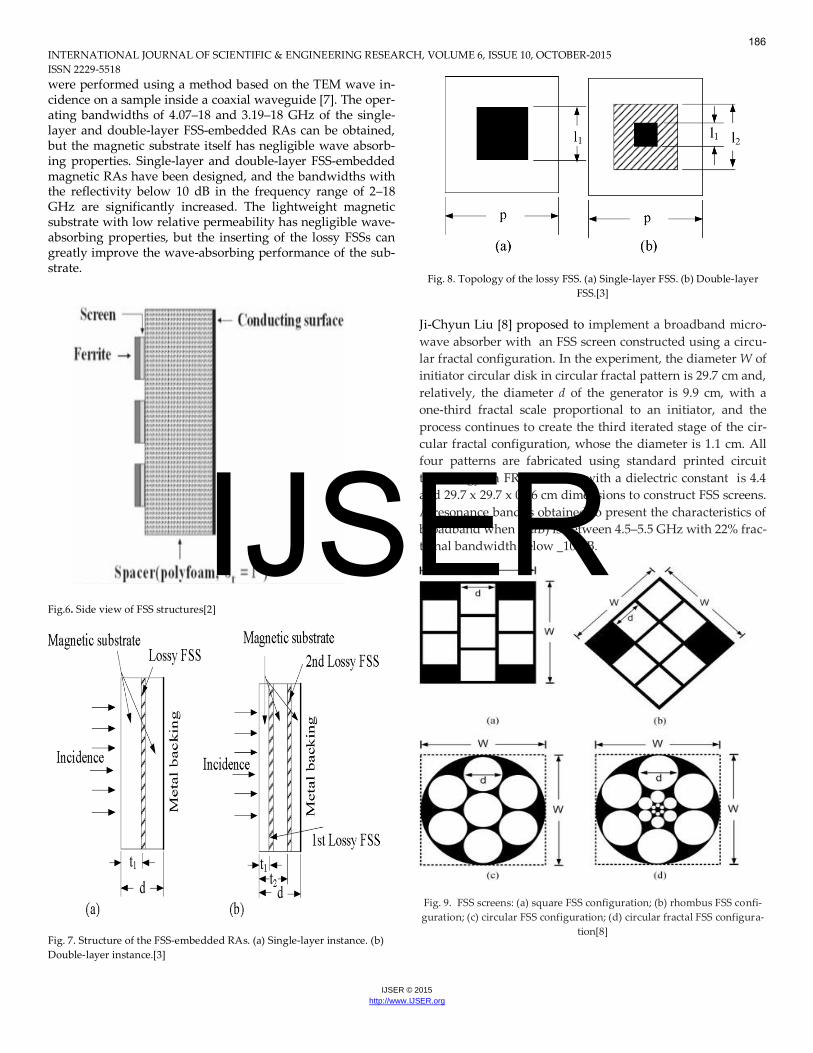
Fig. 8. Topology of the lossy FSS. (a) Single-layer FSS. (b) Double-layer
FSS.[3]
Ji-Chyun Liu [8] proposed to implement a broadband micro-
wave absorber with an FSS screen constructed using a circu-
lar fractal configuration. In the experiment, the diameter W of
initiator circular disk in circular fractal pattern is 29.7 cm and,
relatively, the diameter d of the generator is 9.9 cm, with a
one-third fractal scale proportional to an initiator, and the
process continues to create the third iterated stage of the cir-
cular fractal configuration, whose the diameter is 1.1 cm. All
four patterns are fabricated using standard printed circuit
technology on FR4 substrate with a dielectric constant is 4.4
and 29.7 x 29.7 x 0.16 cm dimensions to construct FSS screens.
A resonance band is obtained to present the characteristics of
broadband when R(dB) is between 4.5–5.5 GHz with 22% frac-
tional bandwidth below _10 dB.
Fig. 9. FSS screens: (a) square FSS configuration; (b) rhombus FSS confi-
guration; (c) circular FSS configuration; (d) circular fractal FSS configura-
tion[8]
186
IJSER

INTERNATIONAL JOURNAL OF SCIENTIFIC & ENGINEERING RESEARCH, VOLUME 6, ISSUE 10, OCTOBER-2015 ISSN 2229-5518
IJSER © 2015
http://www.IJSER.org
3. CONCLUSION This paper shows the review and survey of techniques and design for the designing of efficient absorber using FSS. By using one of any above mentioned technique some of the li-mitations of conventional FSS characteristics is improved. This review work is done on some characteristics imple-mented through different techniques. Nevertheless, useful solution are still less and suffer from different problems like complexity of structure, reduced bandwidth, reduction of gain etc. Hence, the author feels that further research and more work is needed in these areas. After searched the gap of research paper, reached at the point where is the a design has been discussed in this paper based on finite-difference time-domain method by CST Microwave studio software. In this design all the techniques will be used for analysis the parame-ters FSS.
REFERENCES:
[1] Hang Zhou __ Experimental Demonstration of An Absorp-
tive/Transmissive FSS With Magnetic Material, IEEE Transactions
on Antennas and Propagation, Volume:13, 2014.
[2] Ji-Chyun Liu __ IMPLEMENTATION OF BROADBAND MICRO-
WAVE ABSORBER USING FSS SCREENS COATED WITH
Ba(MnTi)Fe10O19 FERRITE, MICROWAVE AND OPTICAL
TECHNOLOGY LETTERS , Vol. 41, No. 4, May 20 2004.
[3] Liangkui Sun __ Design of a Lightweight Magnetic Radar Absorber
Embedded With Resistive FSS, Volume:11, 2012.
[4] D. Yuping, Y. Yang, H. Ma, L. Shunhua, C. Xiaodong, and C. Hui-
feng, “Absorbing properties of -manganese dioxide/carbon black
doublelayer composites,” J. Phys. D, Appl. Phys., vol. 41, no. 12, p.
125403, 2008.
[5] J. T. Jiang, L. Zhen, B. Y. Zhang, W. Z. Shao, andC. Y. Xu, “Im-
provement on electromagnetic absorbing performance of Al B O
w/Co composite particles through heat treatment,” Scripta Mater.,
vol. 59,no. 9, pp. 967–970, 2008.
[6] H. Y. Chen, H. B. Zhang, and L. J. Deng, “Design of an ultra-thin
magnetic-type radar absorber embedded with FSS,” IEEE Antennas
Wireless Propag. Lett., vol. 9, pp. 899–901, 2010.
[7] Y. J. An, K. Nishida, Y. Yamamoto, S. Ueda, and T. Deguchi, “Mi-
crowave absorber properties of magnetic and dielectric composite
materials,” Electron. Commun., vol. 93, no. 4, pp. 18–26, 2010.
[8] Ji-Chyun __ Design And Analysis Of Broadband Microwave Absor-
ber Utilizing Fss Screen Constructed With Circular Fractal Configu-
rations, Microwave And Optical Technology Letters , Vol. 48, No. 3,
March 2006.
187
IJSER