review optical phase conjugation: principles, techniques, and...
TRANSCRIPT
Progress in Quantum Electronics 26 (2002) 131–191
Review
Optical phase conjugation: principles,techniques, and applications
Guang S. He*
Institute for Lasers, Photonics and Biophotonics, State University of New York at Buffalo,
Buffalo, NY 14260-3000, USA
Abstract
Over the last three decades, optical phase conjugation (OPC) has been one of the major
research subjects in the field of nonlinear optics and quantum electronics. OPC defines usually
a special relationship between two coherent optical beams propagating in opposite directions
with reversed wave front and identical transverse amplitude distributions. The unique feature
of a pair of phase-conjugate beams is that the aberration influence imposed on the forward
beam passed through an inhomogeneous or disturbing medium can be automatically removed
for the backward beam passed through the same disturbing medium.
To date there have been three major technical approaches that can efficiently produce the
backward phase-conjugate beam. The first approach is based on the degenerate (or partially
degenerate) four-wave mixing processes, the second is based on various backward simulated
(Brillouin, Raman, Rayleigh-wing or Kerr) scattering processes, and the third is based on one-
photon or multi-photon pumped backward stimulated emission (lasing) processes. Among
these three different approaches, there is a common physical mechanism that plays the same
essential role in generating a backward phase-conjugate beam, which is the formation of the
induced holographic grating and the subsequent wave-front restoration via a backward
reading beam. In most experimental studies, certain types of resonance enhancements of
induced refractive-index changes are desirable for obtaining higher grating-diffraction
efficiency.
The momentum of OPC studies has recently become even stronger because there are more
prospective potentials and achievements for applications. OPC-associated techniques can be
successfully utilized in many different application areas: such as high-brightness laser
oscillator/amplifier systems, cavity-less lasing devices, laser target-aiming systems, aberration
correction for coherent-light transmission and reflection through disturbing media, long
distance optical fiber communications with ultra-high bit-rate, optical phase locking and
coupling systems, and novel optical data storage and processing systems. Published by Elsevier
Science Ltd.
*Fax: +1-716-645-6945.
E-mail address: [email protected] (G.S. He).
0079-6727/02/$ - see front matter Published by Elsevier Science Ltd.
PII: S 0 0 7 9 - 6 7 2 7 ( 0 2 ) 0 0 0 0 4 - 6

PACS: 42.65.Hw
Keywords: Optical phase conjugation; Nonlinear wave-mixing; Stimulated scattering; Stimulated
emission; Laser-induced phase grating; Laser holography
Contents
1. Introduction to optical phase conjugation (OPC) . . . . . . . . . . . . . . . . . 133
2. Definitions and features of phase conjugate waves (PCWs) . . . . . . . . . . . . 134
2.1. Backward degenerate PCW. . . . . . . . . . . . . . . . . . . . . . . . . . 134
2.2. Backward nondegenerate PCW. . . . . . . . . . . . . . . . . . . . . . . . 137
2.3. Forward PCW . . . . . . . . . . . . . . . . . . . . . . . . . . . . . . . . 137
3. Methods for producing optical phase conjugated waves (PCWs) . . . . . . . . . 139
3.1. Backward degenerate four-wave mixing (FWM) . . . . . . . . . . . . . . . 139
3.2. Backward nondegenerate FWM . . . . . . . . . . . . . . . . . . . . . . . 144
3.3. Forward FWM . . . . . . . . . . . . . . . . . . . . . . . . . . . . . . . . 145
3.4. Forward three-wave mixing in a second-order medium . . . . . . . . . . . 148
3.5. Backward stimulated scattering . . . . . . . . . . . . . . . . . . . . . . . 149
3.6. Backward stimulated emission (lasing) . . . . . . . . . . . . . . . . . . . . 150
4. Studies of PCW generation via four-wave mixing (FWM) . . . . . . . . . . . . . 150
4.1. Experiments . . . . . . . . . . . . . . . . . . . . . . . . . . . . . . . . . 150
4.1.1. The nonlinear reflectivity R . . . . . . . . . . . . . . . . . . . . . 151
4.1.2. Fidelity of the phase-conjugate beam . . . . . . . . . . . . . . . . 151
4.1.3. Polarization property of the phase-conjugate beam . . . . . . . . . 152
4.1.4. Temporal behavior of the pulsed phase-conjugate wave . . . . . . . 152
4.2. Some typical results . . . . . . . . . . . . . . . . . . . . . . . . . . . . . 152
4.2.1. Degenerate FWM in nonresonant media . . . . . . . . . . . . . . . 153
4.2.2. PCW generation in resonant media . . . . . . . . . . . . . . . . . 154
4.2.3. PCW generation via nondegenerate FWM . . . . . . . . . . . . . . 156
4.3. Nonlinear media . . . . . . . . . . . . . . . . . . . . . . . . . . . . . . . 158
5. PCW generation via backward stimulated scattering . . . . . . . . . . . . . . . . 160
5.1. Phase-conjugation properties of backward stimulated scattering . . . . . . . 160
5.2. Theoretical explanations: quasi-collinear and nondegenerate
FWM model . . . . . . . . . . . . . . . . . . . . . . . . . . . . . . . . . 164
5.3. Mathematical treatment in unfocused-beam approximation . . . . . . . . . 166
6. PCW generation via backward stimulated emission (lasing) . . . . . . . . . . . . 169
6.1. Single-pass stimulated emission from a two-photon pumped (TPP)
lasing medium . . . . . . . . . . . . . . . . . . . . . . . . . . . . . . . . 169
6.2. Phase-conjugation properties of TPP backward stimulated emission . . . . 169
6.3. Explanations for the phase-conjugation nature of backward stimulated
emission . . . . . . . . . . . . . . . . . . . . . . . . . . . . . . . . . . . 173
6.4. Phase-conjugation properties of one-photon pumped backward stimulated
emission . . . . . . . . . . . . . . . . . . . . . . . . . . . . . . . . . . . 176
6.5. Phase-conjugation via three-photon pumped backward stimulated emission. 176
G.S. He / Progress in Quantum Electronics 26 (2002) 131–191132

7. Applications of OPC . . . . . . . . . . . . . . . . . . . . . . . . . . . . . . . . 177
7.1. Potentials of OPC applications . . . . . . . . . . . . . . . . . . . . . . . . 177
7.1.1. Laser oscillator systems with a phase-conjugate reflector . . . . . . 179
7.1.2. Laser amplifier systems with a phase-conjugate reflector . . . . . . 179
7.1.3. Laser target-aiming and auto-focusing systems . . . . . . . . . . . 179
7.1.4. Laser weapon systems . . . . . . . . . . . . . . . . . . . . . . . . 179
7.1.5. Laser identification and rescue systems . . . . . . . . . . . . . . . 180
7.2. Some examples of OPC application studies . . . . . . . . . . . . . . . . . 181
7.2.1. Laser oscillator/amplifier systems using stimulated Brillouin
scattering mirror . . . . . . . . . . . . . . . . . . . . . . . . . . . 181
7.2.2. OPC-associate nonlinear spectroscopy . . . . . . . . . . . . . . . . 181
7.2.3. OPC-associate phase-locking . . . . . . . . . . . . . . . . . . . . . 181
7.2.4. OPC-associate interferometry . . . . . . . . . . . . . . . . . . . . 181
7.2.5. OPC-associated optical data processing . . . . . . . . . . . . . . . 181
7.3. Midway OPC for fiber communication systems . . . . . . . . . . . . . . . 182
7.3.1. Dispersion-shifted fiber (DSF) systems . . . . . . . . . . . . . . . . 184
7.3.2. Semiconductor optical amplifier (SOA) systems . . . . . . . . . . . 185
7.3.3. Second-order nonlinear waveguide systems . . . . . . . . . . . . . 185
References . . . . . . . . . . . . . . . . . . . . . . . . . . . . . . . . . . . . . . . . 186
1. Introduction to optical phase conjugation (OPC)
Optical phase conjugation (OPC)1 is a new laser-based technique developed since1970s. As this technique is feasible for use in many significant applications, the studyof OPC has become one of the most active research subjects in the areas of nonlinearoptics and quantum electronics [1–8].
Before the 1960s and the advent of lasers, it was well known that there were twoimpossibilities within the regime of conventional optics. The first was that thebrightness of any given light beam cannot be increased via any type of opticalimaging systems or specially designed devices. The second was that a perfect andreversible optical imaging system was impossible because of the aberration influencefrom optical elements and propagating media. The first impossibility was removedafter the advent of laser oscillators and amplifiers. The second restraint could also bereleased by utilizing the OPC technique.
In general, a pair of optical waves are phase conjugated to each other if theircomplex amplitude functions are conjugated with respect to their phase factors.Optical phase-conjugate waves can be generated through various nonlinear opticalprocesses (such as four-wave mixing, three-wave mixing, backward stimulatedscattering, and others). They can also be generated through one-photon or multi-photon pumped backward stimulated emission processes in a lasing medium. In
1 Some parts of this review, including the descriptions of OPC principles and a number of selected
experimental results, were previously covered in Chapter 9 of the author’s recent book [5]. The present
review, however, has a broader scope, containing more techniques, the latest progress, as well as additional
applications.
G.S. He / Progress in Quantum Electronics 26 (2002) 131–191 133
many cases, however, one can say that the principles of the major methods forgenerating optical phase-conjugate waves are based on the intense light-inducedholographic gratings and subsequent wavefront reconstruction.
In the area of OPC-related studies, a huge number (more than thousands) ofresearch papers and conference presentations have been published since 1970s. Mostof them were based on the degenerate four-wave mixing method in various types ofnonlinear media with minor technical modifications. It is impossible and notnecessary to mention all (even majority) of them in this review paper. Instead, only avery limited number of publications have been cited here, as they are (i) the originalpapers with the significance of novelty or innovation, (ii) the earlier studiesestablishing the basic understanding of related effects or phenomena, and (iii) someselected examples from a large number of quite similar studies.
2. Definitions and features of phase conjugate waves (PCWs)
2.1. Backward degenerate PCW
The term optical phase conjugation (OPC) is usually used to describe the wavefrontreversion property of a backward propagating optical wave with respect to a forwardpropagating wave. Suppose there is an input quasi-plane-monochromatic wave witharbitrary phase distortion deviated from an ideal plane-monochromatic wave, i.e.,
Eðz; x; y;oÞ ¼ Eðz;x; yÞeiot ¼ A0ðz;x; yÞei½kzþjðz;x;yÞeiot: ð1Þ
Here, z is the longitudinal variable along the propagation direction, x and y are theradial variables along the beam section, o is the circular frequency of the opticalfield, k ¼ n0=ð2plÞ is the magnitude of the corresponding wave vector, n0 is linearrefractive-index of the propagating medium, Eðz; x; yÞ is the complex amplitudefunction, A0ðz;x; yÞ is the real amplitude function, and, finally, jðz; x; yÞ is the phase-distortion function describing the deviation of the real wavefront from an ideal planewave. If there is a backward propagating wave, which can be expressed as
E0ðz;x; y;oÞ ¼ a Enðz; x; yÞeiot ¼ a A0ðz;x; yÞei½kzþjðz;x;yÞeiot; ð2Þ
where a is any real constant, then the field E0ðz;x; y;oÞ is defined as backwardfrequency-degenerate phase conjugate wave of the original forward field Eðz;x; y;oÞ.
There are two simple examples for phase conjugate waves. First, if the incidentwave is an ideal plane wave with jðz;x; yÞ 0; after normal reflection from an idealplane mirror, the reflected wave will be phase conjugate with the incident wave, asshown in Fig. 1(a). Second, if the incident wave is an ideal spherical wave, afternormal reflection from an perfect spherical mirror, the curvature of which is thesame as that of the incident wave front, the reflected wave will also be phaseconjugate with respect to the incident wave, as shown in Fig. 1(b). However, in bothcases, if the wavefront of the incident wave or the surface of the mirror is not perfect,the reflected wave can no longer be an ideal phase conjugate wave of the incidentwave.
G.S. He / Progress in Quantum Electronics 26 (2002) 131–191134

In a more general case, the incident wave may exhibit an arbitrary irregularwavefront; even so, we can still generate its backward phase-conjugate wave from anonlinear medium by virtue of various nonlinear optical processes. In this case, thenonlinear medium plays the role of a phase-conjugate reflector that creates abackward wave having a reversal wavefront distribution with respect to thepropagation direction, as shown schematically in Fig. 1(c).
Fig. 2 schematically depicts the behavior of two different reflected wavesbackward passing through an inhomogeneous or randomly disturbing medium.One is reflected from an ordinary mirror and the other from a phase conjugatereflector. As shown in Fig. 2(a), an initial plane wave becomes an aberrated waveafter passing through the disturbing medium. If we place a plane mirrorperpendicularly to the propagation direction of this wave, after reflected from thismirror and passing back through the same disturbing medium, the aberrationinfluence of the medium on the wavefront of the output wave will accumulate. Incontrast, as shown in Fig. 2(b), if we replace the plane mirror with a phase-conjugatereflector that creates a phase conjugate wave of the incident beam, then after passingback through the same disturbing medium, the aberration influence will be removedfrom the final output wave. This is the most important and unusual property of thephase conjugate wave compared to an ordinary reflected wave.
To describe these two different processes shown in Fig. 2, we assume that theinitial input wave is an ideal plane wave expressed by
Eðz; x; y;oÞ ¼ A0ðz;x; yÞeikz eiot; ð3Þ
Fig. 1. Three examples of optical phase conjugate waves corresponding to: (a) an ideal plane wave, (b) an
ideal spherical wave, and (c) an arbitrarily disturbed wave.
G.S. He / Progress in Quantum Electronics 26 (2002) 131–191 135

and after passing through a disturbing medium it becomes
E0ðz;x; y;oÞ ¼ A0ðz;x; yÞei½kzþjðz;x;yÞeiot: ð4Þ
Here jðz;x; yÞ is a phase function describing the aberration influence on thewavefront from the disturbing medium. If there is an ordinary plane mirror as shownin Fig. 2(a), the reflected wave will be
E00ðz;x; y;oÞ ¼ %R A0ðz;x; yÞei½kzþjðz;x;yÞeiot; ð5Þ
where %R is the amplitude reflectivity of the mirror. Then after passing back throughthe same medium the output wave can be written as
E000ðz; x; y;oÞ ¼ %R A0ðz; x; yÞei½kzþ2jðz;x;yÞeiot: ð6Þ
In this case the aberration influence for two passes will be doubled.On the other hand, if there is a phase conjugate reflector, as shown in Fig. 2(b), the
reflected wave can be expressed as
E00ðz;x; y;oÞ ¼ %R0 A0ðz;x; yÞei½kzjðz;x;yÞeiot; ð7Þ
where %R0 is the effective amplitude reflectivity of the phase conjugate reflector. In thiscase, after passing back through the same disturbing medium the output wave will be
E000 ¼ %R0 A0ðz; x; yÞei½kzjðz;x;yÞeijðz;x;yÞeiot ¼ %R0 A0ðz;x; yÞeikzeiot: ð8Þ
Here, we see an ideal output plane wave, and the aberration influence from thedisturbing medium can be entirely removed.
(a)
InputWave
OutputWave
TransmittedWave
ReflectedWave
DisturbedMedium
Mirror
(b)
Phase Conjugate Reflector
InputWave
OutputWave
DisturbedMedium
TransmittedWave
ReflectedWave
Fig. 2. (a) An ordinary reflected wave backward passes through a disturbed medium, the aberration
influence is accumulated; (b) a phase conjugate wave backward passes through the disturbed medium, the
aberration influence is removed.
G.S. He / Progress in Quantum Electronics 26 (2002) 131–191136

2.2. Backward nondegenerate PCW
So far we assume that the frequency of the reflected wave is the same as that of theincident wave. This belongs to the category of frequency-degenerate optical phaseconjugation. Later we will show that a frequency-degenerate PCW can be efficientlyproduced by using the backward degenerate four-wave mixing method. However, ina more general case, if there is a backward propagating optical field with a frequencyo0 different from the frequency o of the incident wave, which can be written as
E0ðz;x; y;o0Þ ¼ a Eðz;x; yÞeio0t ¼ a A0ðz; x; yÞei½k0zþjðz;x;yÞeio0t; ð9Þ
then E0ðz;x; y;o0Þ is the backward frequency-nondegenerate phase-conjugate waveof an original field Eðz;x; y;oÞ expressed by Eq. (1). In practice, a frequency-nondegenerate backward PCW can be generated by utilizing the following methods:backward nondegenerate four-wave mixing, backward stimulated scattering withcertain frequency shift, and backward stimulated emission in a lasing medium. In allthese cases, there is a frequency shift between the incident wave and the backwardphase-conjugate wave. It can be both experimentally and theoretically proven thatthe amplitude/phase information carried by the input forward wave of frequency ocan also be restored by the backward PCW with frequency o0: In this case, however,the quality or fidelity of restored information may undergo certain influence ofchromatic aberration when the frequency or wavelength shift is large.
2.3. Forward PCW
Assuming the input wave is described again by Eq. (1), its forward phaseconjugate wave can be defined as
E0ðz;x; y;oÞ ¼ a A0ðz;x; yÞei½kzjðz;x;yÞeiot; ð10Þ
where a is any real constant. In this case two related waves propagate along the samedirection and have the same frequency, therefore, the wave described by Eq. (10) canalso be called the frequency-degenerate forward PCW with respect to the input wavedescribed by Eq. (1).
In a more general case, one can also generate a forward phase conjugate wave witha shifted frequency, such as
E0ðz;x; y;o0Þ ¼ a A0ðz;x; yÞei½k0zjðz;x;yÞeio0t; ð11Þ
where oao0: The wave described by above equation can be called the frequency-nondegenerate forward PCW. The physical meaning of a forward phase conjugatewave described by either Eq. (10) or Eq. (11) can be interpreted as following: itswavefront is reversed but the transverse amplitude distribution and propagationdirection remains the same as the input wave.
The aberration or distortion influence of the propagating medium on the inputwave can be compensated for its forward PCW in two ways, as schematically shownin Fig. 3. Here, it is assumed that the input is an ideal plane wave, that a propagatingmedium will impose considerable distortion upon the wavefront of the input light
G.S. He / Progress in Quantum Electronics 26 (2002) 131–191 137
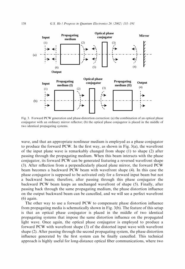
wave, and that an appropriate nonlinear medium is employed as a phase conjugatorto produce the forward PCW. In the first way, as shown in Fig. 3(a), the wavefrontof the input plane wave is remarkably changed from shape (1) to shape (2) afterpassing through the propagating medium. When this beam interacts with the phaseconjugator, its forward PCW can be generated featuring a reversed wavefront shape(3). After reflection from a perpendicularly placed plane mirror, the forward PCWbeam becomes a backward PCW beam with wavefront shape (4). In this case thephase conjugator is supposed to be activated only for a forward input beam but nota backward beam; therefore, after passing through this phase conjugator thebackward PCW beam keeps an unchanged wavefront of shape (5). Finally, afterpassing back through the same propagating medium, the phase distortion influenceon the output backward beam can be cancelled, and we will see a perfect wavefront(6) again.
The other way to use a forward PCW to compensate phase distortion influencefrom propagating media is schematically shown in Fig. 3(b). The feature of this setupis that an optical phase conjugator is placed in the middle of two identicalpropagating systems that impose the same distortion influence on the propagatedlight wave. Once again, the optical phase conjugator is employed to produce aforward PCW with wavefront shape (3) of the distorted input wave with wavefrontshape (2). After passing through the second propagating system, the phase distortioninfluence generated by the first system can be finally cancelled. This technicalapproach is highly useful for long-distance optical fiber communications, where two
(1) (2) (3)
(4)(5)(6)
(a)
(b)
(1) (2) (3) (4)
Propagatingmedium
Optical phase conjugator MirrorInput
Output
Propagatingmedium (I)
Optical phase conjugator Propagating
medium (II)Input Output
Fig. 3. Forward PCW generation and phase-distortion correction: (a) the combination of an optical phase
conjugator with an ordinary mirror reflector; (b) the optical phase conjugator is placed in the middle of
two identical propagating systems.
G.S. He / Progress in Quantum Electronics 26 (2002) 131–191138

spans of the same type of optical fiber can be thought as two identical propagatingsystems.
3. Methods for producing optical phase conjugated waves (PCWs)
In practice, the backward phase conjugate waves (PCWs) can be produced basedon several different physical processes, which include (1) the backward four-wavemixing [9,10], (2) the backward stimulated scattering [11,12], and (3) the backwardstimulated emission (lasing) [13,14]. On the other hand, the forward PCWs can begenerated based on (i) the forward four-wave mixing [15,16], (ii) the special three-wave mixing in a second-order nonlinear medium [17,18], and (iii) photon-echoprocesses in a resonant medium [19,20].
3.1. Backward degenerate four-wave mixing (FWM)
The most popular method to generate a backward degenerate PCW is based onthe so-called backward degenerate four-wave mixing (FWM), proposed first byHellwarth in 1977 [9]. In this case, as shown in Fig. 4, a third-order nonlinearmedium is illuminated simultaneously with two counter-propagating strong planewaves and a signal beam that has an arbitrary wavefront distortion and differentpropagation direction. If these three incident waves have the same frequency o; wemay observe a newly generated wave with the same frequency o but propagatingalong the opposite direction of the signal beam. The following derivation can simplyshow that this newly generated wave is the backward frequency-degenerate PCW ofthe incident signal beam.
Third-orderNonlinear medium
Pump Wave E1(ω)
Pump Wave E2(ω)
Signal Beam E3(ω)
Phase Conjugate Wave E4(ω)
Z
z=0 z=l
Fig. 4. Phase-conjugate wave generation by degenerate four-wave mixing.
G.S. He / Progress in Quantum Electronics 26 (2002) 131–191 139

Assuming the signal beam is propagating along the z-axis, the three incidentmonochromatic waves can be expressed as
E1ðoÞ ¼ a1A1ðrÞeiðotk1rÞ;
E2ðoÞ ¼ a2A2ðrÞeiðotk2rÞ;
E3ðoÞ ¼ a3A3ðzÞeiðotk3zÞ; ð12Þ
where a1 is a unit vector along the light polarization direction of the ith wave,k1 ¼ k2 is the wave vector of the one pump wave, k3 is the absolute value of thewave vector of the signal beam, A1 and A2 are the real amplitude functions of thetwo plane pump waves, and A3 is the complex amplitude function of the signal wave.
According to the principle of FWM, the fourth coherent wave will be generatedthrough the third-order nonlinear polarization response of the medium. This waveand its corresponding nonlinear electric polarization can be written as
Pð3Þ4 ðoÞ ¼ e0wð3Þðo;o;oÞa1a2a3A1A2A
3 eiðotþk3zÞ;
E4ðoÞ ¼ a4A4ðzÞeiðotþk3zÞ:ð13Þ
Here the newly generated wave is propagating along the z direction, and the phase-matching condition is always satisfied because k1 þ k2 ¼ k3 þ k4 0: As a result ofsuch a process, the signal wave will be amplified while the E4 wave is created.
For simplicity, it is assumed that the three incident wave are linearly polarizedalong the same direction (x-axis) and the nonlinear medium is isotropic; therefore,the E4 wave will also be polarized along the x-axis direction. Under this condition,we can neglect the vector property of the fields and write the third-order nonlinearpolarization fields for E3 and E4 waves as
Pð3Þ3 ðoÞ ¼ e0wð3Þe A1A2A
4 eiðotk3zÞ;
Pð3Þ4 ðoÞ ¼ e0wð3Þe A1A2A
3 eiðotþk3zÞ:ð14Þ
Here, wð3Þe ¼ wð3Þxxxxðo;o;oÞ is the effective third-order nonlinear susceptibility value,which is a real quantity for nonresonant interaction or a complex quantity forresonant or near-resonant interaction.
Substituting Eq. (14) into the general expression of nonlinear coupled-waveequations, and assuming the depletion of both, strong pump waves can be neglectedwithin a short interaction length, we then obtain the equation describing theamplitude variation along the z-axis for E3 and E4 waves:
qAn3ðzÞqz
¼ igA4ðzÞ;
qA4ðzÞqz
¼ igA3ðzÞ;
ð15Þ
G.S. He / Progress in Quantum Electronics 26 (2002) 131–191140

where g in general is a complex coupling coefficient determined by
g ¼k3ðoÞ2erðoÞ
wð3Þe A1A2
¼o
2cn0ðoÞwð3Þe A1A2: ð16Þ
Here er and n0 are the linear dielectric constant and refractive index of the nonlinearmedium, respectively.
Under the condition that A1; A2 and, therefore, g are approximately constant, thesolutions of Eq. (15) can be expressed as [21]
A3ðzÞ ¼cos½ gj jðz lÞ
cos½ gj jlA3ð0Þ i
gj jg
sin½ gj jzcos½ gj jl
A4ðlÞ;
A4ðzÞ ¼cos½ gj jzcos½ gj jl
A4ðlÞ þ iggj j
sin½ gj jðz lÞcos½ gj jl
A3ð0Þ;
ð17Þ
where A3 (0) is the initial amplitude of the signal wave on the incident surface of thenonlinear medium. Considering the boundary condition of A4ðlÞ ¼ 0; we obtain thefinal solutions:
A3ðlÞ ¼A3ð0Þ
cos½ gj jl;
A4ð0Þ ¼ iggj j
tan½ gj jlA3ð0Þ:
ð18Þ
From Eq. (13) we know that the wave E4 is counter-propagating to the wave E3; onthe other hand, from the second expression of Eq. (18) we know that the complexamplitude A4ð0Þ is proportional to An
3ð0Þ near the incident surface. Therefore, onecan conclude that the waves E4 and E3 are phase-conjugated to each other and thewhole system plays the role of a phase-conjugate reflector. In this case the nonlinearintensity-reflectivity of the system can be determined from Eq. (18) as
R ¼ A4ð0Þj j2= A3ð0Þj j2¼ tan2½ gj jl: ð19Þ
If ðp=4Þo gj jloð3p=4Þ; then R > 1; indicating an amplification effect of the backwardwave E4: In addition, from the first expression of Eq. (18) we know that A3ðlÞ >A3ð0Þ; i.e., the signal wave E3 will be always amplified through the nonlinearmedium.
In particular, when the following condition is fulfilled:
gj jl ¼p2; ð20Þ
from Eq. (18) we have
A4ð0Þj jA3ð0Þj j
¼ N;A3ðlÞj jA3ð0Þj j
¼ N: ð21Þ
These expressions mean self-oscillation of both waves E3 and E4: In reality, thissituation will not happen because the solutions given by Eq. (18) are valid only forsmall signal gain. When the amplitude changes for waves E3 and E4 are considerablylarge, the amplitude functions A1 and A2 of the pump beams can no longer be treated
G.S. He / Progress in Quantum Electronics 26 (2002) 131–191 141

as constants, therefore the solutions expressed by Eq. (18) are not adequate todescribe the gain behavior of strong signals. Nevertheless, we still can use Eq. (20) asa rough estimation of the effective interaction length (l0) for a given nonlinearmedium, which is
l0Ep
2 gj j¼
cn0ðoÞo
p
wð3Þe
1
A1A2: ð22Þ
From Eq. (18) we can see that the greater value of wð3Þe ¼ wð3Þxxxxðo;o;oÞ the
nonlinear medium has, the stronger reflected wave E4 it can generate. Fornonresonant interaction, wð3Þe is a real and small quantity, and consequently, thenonlinear reflectivity R is quite low. To reach a higher nonlinear reflectivity,researchers have to use resonant or near-resonant effects to increase the wð3Þe
valueof the medium [22].
In the above part of this subsection, it is mathematically proven that a PCW canbe generated through a special degenerate FWM arrangement in a third-ordernonlinear medium. Such a process is essentially related to the four-photonparametric interaction.
In the following part of this subsection, we shall consider a more generalinterpretation that can explain why the PCW can be generated in such a specialFWM arrangement. This model is based on the principle of holography, i.e. two-beam induced volume gratings and the subsequent wavefront reconstruction with thethird beam [1,23].
As shown in Fig. 5, there are two counter-propagating plane pump waves (A1 andA2) passing through a nonlinear medium, and a signal wave A3 is incident upon themedium at an angle y with respect to the pump wave A1: Under this arrangement thebackward propagating wave A4 can be generated through the reflection from twopossible induced gratings. First, let us consider the interference between the twowaves A1 and A3 that will produce nearly parallel interference fringes along thebisector direction of the crossing angle y; as shown in Fig. 5(a). Considering that theinduced refractive-index change of the medium is proportional to the local lightintensity, one may realize that the interference fringes can produce an inducedholographic grating within the nonlinear medium. In this case the pump wave A2 can
θ
A1 A2
A3
A4
Nonlinear Medium
(π−θ)
A1 A2
A3
A4
Nonlinear Medium
d13
d 23
(a) (b)
Fig. 5. Schematics describing the generation of a backward phase conjugate wave via induced holographic
gratings.
G.S. He / Progress in Quantum Electronics 26 (2002) 131–191142
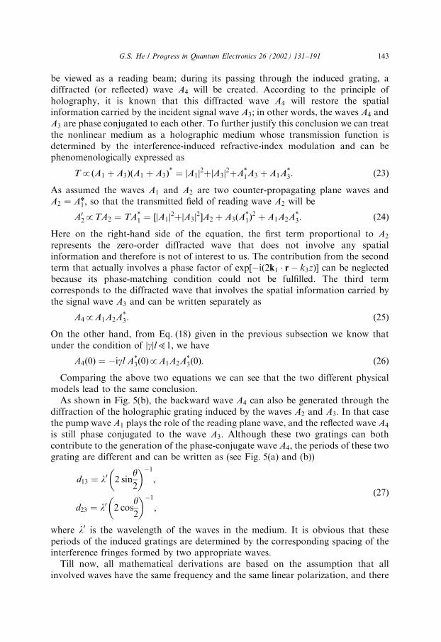
be viewed as a reading beam; during its passing through the induced grating, adiffracted (or reflected) wave A4 will be created. According to the principle ofholography, it is known that this diffracted wave A4 will restore the spatialinformation carried by the incident signal wave A3; in other words, the waves A4 andA3 are phase conjugated to each other. To further justify this conclusion we can treatthe nonlinear medium as a holographic medium whose transmission function isdetermined by the interference-induced refractive-index modulation and can bephenomenologically expressed as
TpðA1 þ A3ÞðA1 þ A3Þ ¼ A1j j2þ A3j j2þA
1A3 þ A1A3: ð23Þ
As assumed the waves A1 and A2 are two counter-propagating plane waves andA2 ¼ An
1 ; so that the transmitted field of reading wave A2 will be
A02pTA2 ¼ TA
1 ¼ ½ A1j j2þ A3j j2A2 þ A3ðA1Þ
2 þ A1A2A3: ð24Þ
Here on the right-hand side of the equation, the first term proportional to A2
represents the zero-order diffracted wave that does not involve any spatialinformation and therefore is not of interest to us. The contribution from the secondterm that actually involves a phase factor of exp½ið2k1 r k3zÞ can be neglectedbecause its phase-matching condition could not be fulfilled. The third termcorresponds to the diffracted wave that involves the spatial information carried bythe signal wave A3 and can be written separately as
A4pA1A2A3: ð25Þ
On the other hand, from Eq. (18) given in the previous subsection we know thatunder the condition of gj jl51; we have
A4ð0Þ ¼ igl A3ð0ÞpA1A2A
3ð0Þ: ð26Þ
Comparing the above two equations we can see that the two different physicalmodels lead to the same conclusion.
As shown in Fig. 5(b), the backward wave A4 can also be generated through thediffraction of the holographic grating induced by the waves A2 and A3: In that casethe pump wave A1 plays the role of the reading plane wave, and the reflected wave A4
is still phase conjugated to the wave A3: Although these two gratings can bothcontribute to the generation of the phase-conjugate wave A4; the periods of these twograting are different and can be written as (see Fig. 5(a) and (b))
d13 ¼ l0 2 siny2
1
;
d23 ¼ l0 2 cosy2
1
;
ð27Þ
where l0 is the wavelength of the waves in the medium. It is obvious that theseperiods of the induced gratings are determined by the corresponding spacing of theinterference fringes formed by two appropriate waves.
Till now, all mathematical derivations are based on the assumption that allinvolved waves have the same frequency and the same linear polarization, and there
G.S. He / Progress in Quantum Electronics 26 (2002) 131–191 143
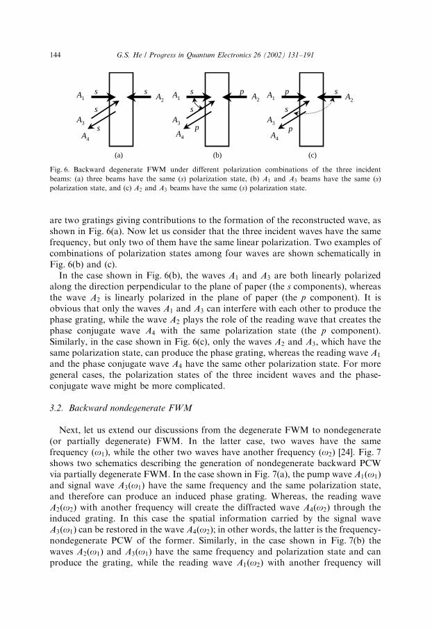
are two gratings giving contributions to the formation of the reconstructed wave, asshown in Fig. 6(a). Now let us consider that the three incident waves have the samefrequency, but only two of them have the same linear polarization. Two examples ofcombinations of polarization states among four waves are shown schematically inFig. 6(b) and (c).
In the case shown in Fig. 6(b), the waves A1 and A3 are both linearly polarizedalong the direction perpendicular to the plane of paper (the s components), whereasthe wave A2 is linearly polarized in the plane of paper (the p component). It isobvious that only the waves A1 and A3 can interfere with each other to produce thephase grating, while the wave A2 plays the role of the reading wave that creates thephase conjugate wave A4 with the same polarization state (the p component).Similarly, in the case shown in Fig. 6(c), only the waves A2 and A3; which have thesame polarization state, can produce the phase grating, whereas the reading wave A1
and the phase conjugate wave A4 have the same other polarization state. For moregeneral cases, the polarization states of the three incident waves and the phase-conjugate wave might be more complicated.
3.2. Backward nondegenerate FWM
Next, let us extend our discussions from the degenerate FWM to nondegenerate(or partially degenerate) FWM. In the latter case, two waves have the samefrequency (o1), while the other two waves have another frequency (o2) [24]. Fig. 7shows two schematics describing the generation of nondegenerate backward PCWvia partially degenerate FWM. In the case shown in Fig. 7(a), the pump wave A1ðo1Þand signal wave A3ðo1Þ have the same frequency and the same polarization state,and therefore can produce an induced phase grating. Whereas, the reading waveA2ðo2Þ with another frequency will create the diffracted wave A4ðo2Þ through theinduced grating. In this case the spatial information carried by the signal waveA3ðo1Þ can be restored in the wave A4ðo2Þ; in other words, the latter is the frequency-nondegenerate PCW of the former. Similarly, in the case shown in Fig. 7(b) thewaves A2ðo1Þ and A3ðo1Þ have the same frequency and polarization state and canproduce the grating, while the reading wave A1ðo2Þ with another frequency will
A2A1
A3
A4
s s
s
s
A1
A3
A4
s p
s
p
A1
A3
A4
p s
s
p
(a) (b) (c)
A2 A2
Fig. 6. Backward degenerate FWM under different polarization combinations of the three incident
beams: (a) three beams have the same (s) polarization state, (b) A1 and A3 beams have the same (s)
polarization state, and (c) A2 and A3 beams have the same (s) polarization state.
G.S. He / Progress in Quantum Electronics 26 (2002) 131–191144

create the diffracted wave A4ðo2Þ: In this case A4ðo2Þ is phase-conjugated withA3ðo1Þ:
The processes described above are essentially the same as that observed when weuse two beams of the same frequency to produce a hologram, and then use anotherbeam with a different frequency to read this hologram. In that case the diffractedbeam has the same frequency as the reading beam, but the reconstructed spatialstructure of this beam may be influenced by the wavelength difference between therecording beams and the reading beam.
In the latter sections we shall indicate that the induced holographic grating modelis not only useful to explain the generation of PCW via FWM processes, but alsosuitable to explain the PCW generation through either the backward stimulatedscattering or the backward stimulated emission (lasing) processes.
3.3. Forward FWM
Generally speaking, the forward optical PCW can be generated in a third-ordernonlinear medium via specially designed forward FWM arrangement.
Firstly, let us consider the principle of utilizing a forward degenerate FWM setupto generate the degenerate forward PCW [16]. Such an arrangement is schematicallyshown in Fig. 8, where two strong pump beams (beam 1 and beam 2) of the samefrequency are passing through the nonlinear medium with a small intersection angle(y12) in a horizontal plane. The signal beam 3 with the same frequency is incidentnearly in a vertical plane at a small intersection angle (y32) with respect to beam 2. Byadjusting the latter angle and the spatial overlapping in the medium among the threebeams until beam 3 is exactly located at a circle, which passes through beams 1 and 2with an angular diameter of y12 in an observation screen, a newly generated coherentemission beam 4 of the same frequency might be observed at the locationsymmetrical to that of beam 3 along the circle. Meanwhile, after passing throughthe nonlinear medium, the intensity of beam 3 is increased. This observation can bewell understood if we recognize it as a result of degenerate four-photon parametricprocesses. This involves the annihilation of two photons from beams 1 and 2, and the
A1(ω1)
A3(ω1)
A2(ω2)
A4(ω2)
Nonlinear Medium
(a)
A1(ω2)
A3(ω1)
A2(ω1)
A4(ω2)
Nonlinear Medium
(b)
Fig. 7. Schematics describing the generation of the backward nondegenerate PCW via partially degenerate
FWM in a nonlinear medium.
G.S. He / Progress in Quantum Electronics 26 (2002) 131–191 145

simultaneous creation of two photons contributing to beams 3 and 4. The phase-matching condition in this case can be written as
k1ðoÞ þ k2ðoÞ ¼ k3ðoÞ þ k4ðoÞ: ð28Þ
Neglecting the depletion of two pump beams within the thin nonlinear medium, wecan readily prove that
A4ðoÞpA3ðoÞ; ð29Þ
i.e. beam 4 is the forward PCW of the signal beam 3. Here we further extend thedefinition of forward PCW when two mutually conjugated forward beams may havedifferent propagation directions.
In the arrangement described above, generation of beam 4 can also be explainedwell by the model of holographic grating. According to this model, the newlygenerated beam 4 is not only a result of four-photon parametric amplificationprocess, but also is from the refraction of induced gratings. Specifically, there may betwo contributions from grating diffraction (or reflection) to the formation of phase-conjugated beam 4: one is from the grating formed by beams 2 and 3 reading bypump beam 1, the other is from the grating formed by beams 1 and 3 reading bypump beam 2. Though it is not easy, it can be done to distinguish the gratingcontribution from the four-photon parametric contribution. The major difference isthat the latter only takes place when three beams arrive at the nonlinear medium atexactly the same time, whereas the former can take place even when one pump beamis delayed with respect to the other, within a certain time interval. In most cases,optical beam-induced gratings can last a certain time period depending on thespecific mechanisms of intensity-dependent refractive index changes of the medium.Moreover, if the grating contribution is the dominant mechanism, multi-spotstructures may be observed in the screen at a high pump level, owing to a higher-order grating diffraction effect [25].
Next, let us consider how to utilize a nondegenerate forward FWM method togenerate the forward PCW. A quite simple experimental approach is shown inFig. 9(a), where a strong pump beam 1 of frequency o1 and a weak signal beam 2 offrequency o2 are passing through a third-order nonlinear medium simultaneously
ScreenNonlinearMedium
Beam1
Beam 2
Beam 3
3
Beam 4(PCW)
θ12
θ32
2
1
Fig. 8. Forward degenerate FWM setup for generating forward PCW.
G.S. He / Progress in Quantum Electronics 26 (2002) 131–191146
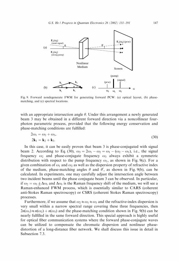
with an appropriate intersection angle y: Under this arrangement a newly generatedbeam 3 may be obtained in a different forward direction via a noncollinear four-photon parametric process, provided that the following energy conservation andphase-matching conditions are fulfilled:
2o1 ¼ o2 þ o3;
2k1 ¼ k2 þ k3:ð30Þ
In this case, it can be easily proven that beam 3 is phase-conjugated with signalbeam 2. According to Eq. (30), o3 ¼ 2o1 o2 ¼ o1 ðo2 o1Þ; i.e., the signalfrequency o2 and phase-conjugate frequency o3 always exhibit a symmetricdistribution with respect to the pump frequency o1; as shown in Fig. 9(c). For agiven combination of o1 and o2 as well as the dispersion property of refractive indexof the medium, phase-matching angles y and y0; as shown in Fig. 9(b), can becalculated. In experiments, one may carefully adjust the intersection angle betweentwo incident beams until the phase conjugate beam 3 can be observed. In particular,if o2 ¼ o17Dor and Dor is the Raman frequency shift of the medium, we will see aRaman-enhanced FWM process, which is essentially similar to CARS (coherentanti-Stokes Raman spectroscopy) or CSRS (coherent Stokes Raman spectroscopy)processes.
Furthermore, if we assume that o2Eo1Eo3 and the refractive-index dispersion isvery small within a narrow spectral range covering these three frequencies, then2nðo1ÞEnðo2Þ þ nðo3Þ and the phase-matching condition shown in Fig. 9(b) can benearly fulfilled in the same forward direction. This special approach is highly usefulfor optical fiber communication systems where the forward phase-conjugate wavescan be utilized to compensate the chromatic dispersion and nonlinear phase-distortion of a long-distance fiber network. We shall discuss this issue in detail inSubsection 7.3.
θ θk1 k1
k2k3
(b) ωω3 ω1 ω2
(c)
(pump)
(pcw)(signal)
Screen
NonlinearMedium
E1(ω1)(strong pump)
θ
E2(ω2)(weak signal)
θE3(ω3) (pcw)
(a)
Fig. 9. Forward nondegenerate FWM for generating forward PCW: (a) optical layout, (b) phase-
matching, and (c) spectral locations.
G.S. He / Progress in Quantum Electronics 26 (2002) 131–191 147

3.4. Forward three-wave mixing in a second-order medium
From historical viewpoint, the earliest suggestion for generating PCW based on aspecial three-wave mixing in the second-order nonlinear crystal was given by Yarivin 1976 [17]. It is well known that such a crystal can be used for second harmonicgeneration (SHG) at frequency of 2o pumping with a strong fundamental wave atfrequency of o: For the purpose of PCW generation [18,26,27], one can let thefundamental beam and SHG beam pass through another second-order nonlinearcrystal together as shown in Fig. 10. For the second crystal the input fields can bewritten as (neglecting the polarization property of both beams):
E1ðoÞ ¼ A1ðoÞei½otkðoÞz;
E2ð2oÞ ¼ A2ð2oÞei½2otkð2oÞz;ð31Þ
which induce a second-order nonlinear polarization wave described by
Pð2Þ3 ðoÞ ¼ e0wð2Þe ð2o;oÞA2ð2oÞA
1ðoÞeiðot½kð2oÞkðoÞzÞ: ð32Þ
Here wð2Þe is the effective second-order nonlinear susceptibility of the second crystal.Assuming that the phase-matching requirement in this crystal is satisfied, i.e.kð2oÞ ¼ 2kðoÞ or nð2oÞ ¼ nðoÞ; then P
ð2Þ3 ð2oÞ will emit the third optical field of same
frequency:
E3ðoÞpwð2Þe A2ð2oÞA1ðoÞe
i½otkðoÞz: ð33Þ
Here it is assumed that E2ð2oÞ is a strong pump wave with a negligible depletionwithin the second nonlinear crystal, and E1ðoÞ is a weak signal beam carrying certainamplitude/phase information. From Eq. (33) one can see that E3ðoÞ is a forwardPCW of the signal wave E1ðoÞ:
Second-ordercrystal 1
Second-ordercrystal 2
E1(ω)
E3(ω)(pcw)
E2(2ω)
E0(ω)
Phase-object plate
E3
E1
E2
2ωω
Ei(ωi)(pcw)
Es(ωs)
Ep(ωp)
Ep
ωp
Es
ωs
Ei
ωi
(a)
(b)
Second-ordercrystal ωp /2
Fig. 10. Three-wave mixing for generating forward PCW in a second-order nonlinear crystal: (a)
degenerate difference-frequency generation, (b) quasi-degenerate difference-frequency generation.
G.S. He / Progress in Quantum Electronics 26 (2002) 131–191148

In practice, there are two ways to separate the phase-conjugate E3ðoÞ wave fromthe transmitted signal wave E1ðoÞ: The first way is to distinguish one wave from theother by their polarization status. For example, under Type II phase-matchingcondition in a negative uniaxial crystal, the pump wave E2ð2oÞ and signal waveE1ðoÞ can both be extraordinary rays, while the phase-conjugate wave E3ðoÞ will bean ordinary ray. The second way is to employ a near-degenerate optical parametricamplification process in a second-order nonlinear crystal, where the frequency os ofa signal wave is close (not equal) to the half of a strong pump frequency op; i.e.osEop=2: Under similar experimental conditions as that mentioned above, aforward coherent wave can be generated in the crystal at a new frequency of oi ¼op os; as shown in Fig. 10(b). The newly generated (idler) wave EiðoiÞ will bephase-conjugated with the signal wave EsðosÞ: It should be noted that in this case thespectral positions of these two waves are mirror-symmetric with respect to the valueof op=2:
3.5. Backward stimulated scattering
It is well known that upon the excitation of intense and highly directionallaser radiation, various types of stimulated scattering can be observed inappropriate scattering media. The most typical of them are stimulated Ramanscattering [28], stimulated Brillouin scattering [29], stimulated Rayleigh-wingscattering [30], and stimulated Kerr scattering [31]. Generally speaking, stimulatedscattering exhibits the same features as stimulated emission (lasing), such as (i)threshold requirement for pump intensity, (ii) exponential amplificationwithin the gain medium for small signal, (iii) high directionality and brightness ofthe output coherent beam [5].
From the historical point of view, the earliest observation of the opticalphase conjugation (OPC) property was made in the experiment of backwardstimulated Brillouin scattering (SBS) in 1972 [11,12]. Since then researchershave found that the similar OPC behavior can also be observed on thebackward output of other types of stimulated scattering. Those experimentalresults showed that the aberration influence imposed on the pump laserbeam could be automatically canceled in the backward stimulatedscattering beam. In this sense the latter is a nondegenerate backwardphase-conjugate wave of the input pump beam, as there is usually a frequencyshift between the pump frequency and the backward stimulated scatteringfrequency.
However, for a long time, there was lack of a clear theoretical model to explainwhy the similar OPC behavior can be observed via different types of stimulatedscattering even though the physical mechanisms for them are totally different. InSection 5, a quasi-collinear four-wave mixing model is suggested as a commonmechanism for PCW generation via various backward stimulated scatteringprocesses [32].
G.S. He / Progress in Quantum Electronics 26 (2002) 131–191 149

3.6. Backward stimulated emission (lasing)
As mentioned in the preceding subsection, there is a remarkable analogy betweenstimulated scattering and stimulated emission [5]. The only difference between thesetwo processes is that the stimulated emission requires population inversion in alasing medium, whereas the generation of stimulated scattering does not require suchpopulation inversion in a scattering medium. Keeping this analogy in mind, one mayexpect that the same OPC behavior should also be observed in the backwardstimulated emission under proper conditions.
In reality, the superior phase-conjugation property has recently been demon-strated in several two-photon pumped dye lasing systems [14,33]. The results of thesestudies have shown that under proper experimental conditions the backwardstimulated emission from a two-photon pumped gain medium can be a good PCW ofthe input pump beam. In Section 6, the same quasi-collinear four-wave mixingmodel, as presented in Section 5, shall be applied to explain why and under whatconditions one may produce the phase-conjugate backward stimulated emissionfrom a lasing medium excited with one-photon, two-photon, or even three-photonabsorption [34].
4. Studies of PCW generation via four-wave mixing (FWM)
In the area of optical phase conjugation (OPC) research, the majority ofexperimental studies have been done by the degenerate FWM method. The reasonfor this is that the principle and visualization of that method is simple and clear, therequired laser facilities are relatively inexpensive, and most importantly, a greatnumber and broad variety of materials can be employed as nonlinear optical mediafor tests. It should be pointed out that a considerable part of those studies has beenfocused on measuring the nonlinearity of materials themselves, rather thaninvestigating the phase-conjugate properties of backward generated optical beams.
4.1. Experiments
Fig. 11 shows two typical experimental arrangements for observing PCW viabackward degenerate FWM. The common feature of these arrangements is that themaster beam from a laser source is divided into three beams via appropriate mirrorsand beamsplitters. Two of them are used as pump beams and pass through anonlinear medium in a counter-propagating way, while the third beam containingcertain spatial information is incident upon the nonlinear medium with a crossingangle to one of the pump beams. Under these arrangements the backward PCW canbe measured in the direction opposite to that of the incident signal beam. To ensure alonger interaction length, the angle between the signal beam and one of the pumpbeams should be relatively small. In practice, to achieve a higher local intensity thethree incident beams are either weakly focused by a lens system or compressed with areversed beam expander.
G.S. He / Progress in Quantum Electronics 26 (2002) 131–191150

The difference between these two layouts is that, for the former, the backwardpump wave is simply provided by a vertically placed mirror, whereas for the latterthe two counter-propagating pump waves are provided by an optical ring-path. It isnoted that the first arrangement is much simpler than the second. However, thesecond arrangement is more convenient to examine the influences from variouspolarization combinations of three incident beams or to change the intensity ratioamong them. To eliminate the possible optical feedback from the backward phase-conjugate beam into the laser source, one may put an optical isolator near the outputend of the laser device, or simply increase the distance between the laser and thenonlinear medium so that the backward traveling time of the feedback light pulses islonger than the laser-pulse duration.
In experiments the following major aspects have been investigated:
4.1.1. The nonlinear reflectivity R
It is defined as the intensity (or energy) ratio between the incident signal beam andthe backward phase-conjugate beam. According to Eqs. (19) and (16), the value of R
and related coupling parameter g can be approximately expressed as
RE½ gj jl2p wð3Þe A1A2
2l2p wð3Þe
2I1I2l2: ð34Þ
Here, wð3Þe is the effective third-order nonlinear susceptibility value of the medium, I1
and I2 are intensity values of the two pump waves, l is the effective interaction lengthin the nonlinear medium, and gj jl5p=4 is assumed.
4.1.2. Fidelity of the phase-conjugate beam
To examine the aberration-correction capability of the phase-conjugate beam, anaberrating plate, which is usually a glass slide etched by hydrofluoric acid solution,can be placed on the incident path of the signal beam. After passing back through
Laser
Laser
Optical Isolator
Optical Isolator
NonlinearMedium
NonlinearMedium
Mirror
Mirror
A1
A2
A3
A4
A1
A2A3
A4
AberratingPlate(a)
(b)
(PCW)
(PCW)
Fig. 11. Two typical experimental setups for PCW generation via degenerate four-wave mixing.
G.S. He / Progress in Quantum Electronics 26 (2002) 131–191 151

the same aberrating plate, the aberration influence on the phase-conjugate beammight be entirely or partially removed depending on the fidelity of wavefrontreconstruction of that beam.
4.1.3. Polarization property of the phase-conjugate beam
As we briefly mentioned in Subsection 3.1, the polarization behavior of PCW isdependent on the polarization states of the three incident beams. Hence, from thestudy of influences of various polarization combinations among the three inputwaves, researchers may have a better understanding of the related processes.
4.1.4. Temporal behavior of the pulsed phase-conjugate wave
To test the dynamic response of the PCW generation via FWM arrangements, ashort- or ultrashort-pulse laser source should be employed to provide the three inputpulsed waves. Letting two writing pulses be incident on the sample simultaneously toproduce a phase-grating, and delaying the third reading pulse, one may determinewhether the four-photon parametric interaction or the induced phase-grating effectis the main mechanism that leads to PCW generation under given experimentalconditions. If the induced grating effect is the major origin, one may furtherdetermine what is the dominant mechanism leading to the induced refractive-indexchanges. There are many mechanisms that can cause intensity-dependent refractive-index changes in nonlinear media, including (a) electronic cloud distortion,(b) intramolecular (Raman) motion, (c) molecular (Kerr) reorientation, (d) opto-electrostriction, (e) photorefractive effect in doped second-order materials,(f) population change, and (g) opto-thermal effect [5]. Different mechanisms havedifferent time-response characteristics, therefore, they can be experimentallyidentified by measuring the rising and decaying behavior of the induced gratings.Table 1 summarizes the roughly estimated values of rise-time and decay-time fordifferent mechanisms causing refractive-index changes in commonly used nonlinearmedia.
4.2. Some typical results
The most experimental studies via FWM arrangements can be classified into threebroad categories: one is based on nonresonant media, another is based on resonant
Table 1
Estimated values of trise and trelax for different mechanisms causing refractive-index changes
Mechanism Rise-time (s) Relaxation-time (s) Resonant enhancement
Electronic cloud distortion p(1015–1016) p(1015–1016) No
Yes
Intramolecular motion p(1012–1014) p(1012–1014) Yes
Molecular reorientation p(1012–1013) p(1011–1012) No
Electrostriction X(109–1010) X(109–1010) No
Yes
Population change E(1010–1013) X(108–1010) Yes
Opto-thermal effect E(108–1010) X(103–106) Yes
G.S. He / Progress in Quantum Electronics 26 (2002) 131–191152
media, and the third is based on photorefractive materials. Generally speaking, thenonlinear reflectivity is rather low when the nonresonant media are used. In contrast,the nonlinear reflectivity can be significantly increased when an enhancement of thethird-order nonlinearity of nonlinear medium is introduced.
4.2.1. Degenerate FWM in nonresonant media
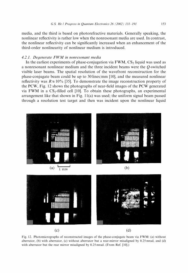
In the earliest experiments of phase-conjugation via FWM, CS2 liquid was used asa nonresonant nonlinear medium and the three incident beams were the Q-switchedvisible laser beams. The spatial resolution of the wavefront reconstruction for thephase-conjugate beam could be up to 30 lines/mm [10], and the measured nonlinearreflectivity was RE10% [35]. To demonstrate the image reconstruction property ofthe PCW, Fig. 12 shows the photographs of near-field images of the PCW generatedvia FWM in a CS2-filled cell [10]. To obtain these photographs, an experimentalarrangement like that shown in Fig. 11(a) was used; the uniform signal beam passedthrough a resolution test target and then was incident upon the nonlinear liquid
Fig. 12. Photomicrographs of reconstructed images of the phase-conjugate beam via FWM: (a) without
aberrator, (b) with aberrator, (c) without aberrator but a rear-mirror misaligned by 0.25 mrad, and (d)
with aberrator but the rear mirror misaligned by 0.25 mrad. (From Ref. [10].)
G.S. He / Progress in Quantum Electronics 26 (2002) 131–191 153

sample. The photographs shown in Fig. 12(a) and (b) were obtained without andwith placing an aberrator (a piece of clear glass cut from the side of a bottle) in thepath of the incident signal beam, respectively. The photographs shown in Fig. 12(c)and (d) were obtained without and with placing the aberrator on the path, when therear reflective mirror that provided the backward pump beam was misadjusted by0.25 mrad vertically. One can see in Fig. 12(c) that the reconstructed image is stillclear and just slightly shifted vertically. However, in Fig. 12(d) the image is severelydistorted because the backward-generated beam (diffracted from the inducedgratings) passed through different portions of the aberrator; therefore the originalaberration cannot be corrected.
Some early experimental studies were performed on the semiconductor crystalswith 10.6 mm radiation from pulsed CO2 laser devices. For example, using apolycrystalline Ge bulk sample as the nonlinear medium, the measured nonlinearreflectivity was RE2% at a pump intensity level of B1 MW/cm2 [36]. In a similarexperiment, the Hg1xCdxTe alloy was used as a nonlinear medium, and themeasured nonlinear reflectivity was RE9%; it was suggested that the nonlinearity ofthis medium was due to conduction-band nonparabolicity [37].
Another example was the use of the MBBA liquid crystal as a nonresonantnonlinear medium. In that case, the three input beams were from a 694.3 nm Q-switched ruby laser operated on a single longitudinal/transverse mode in atemperature range of 45B551C. The measured maximum nonlinear reflectivitycould be as high as RE230% provided that the two pump beams were circularlypolarized in the opposite sense [38].
4.2.2. PCW generation in resonant media
As mentioned before, in order to achieve a higher nonlinear reflectivity, the valueof effective third-order nonlinear susceptibility for the medium should be as large aspossible. For this reason researchers prefer to choose resonant media in whichcertain types of resonance enhancements of wð3Þe can be utilized.
In early experiments the metal vapors were used as resonant nonlinear media[39,40]. One example was the use of Na vapor pumped by 0.5896 mm laser beamsnear the D-resonant line position with a detuning of 1.25 cm1. When the intensitiesfor the pump beam and signal beam were 40 and 0.3 kW/cm2, respectively, themeasured nonlinear reflectivity was as high as RE102; and the spatial resolution ofthe phase-conjugate beam was measured to be 4 lines/mm [40]. Fig. 13 shows themeasured gain data for the signal beam and phase-conjugate beam as a function ofthe pump intensity; the theoretical curves shown in the same figure were given byEq. (18). One can see in Fig. 13 that when the pump intensity was higher thanB30 kW/cm2, the obvious gain saturation for both beams occurred. In addition, theoscilloscope traces of the input pump pulse and phase-conjugate pulse are shown inthe inset of Fig. 13, from which one can see that the pulse duration of the PCW pulsewas three times shorter than that of the signal wave pulse.
There are many resonant media that can be utilized for degenerate FWM studieswith one-photon resonant enhancement [23,41–46]. In one early experiment, crystalsof Nd:YAG, Cr:Al2O3, KCl:ReO4, etc., were employed for performing FWM, the
G.S. He / Progress in Quantum Electronics 26 (2002) 131–191154

measured R ranging from 103 to 102 [41]. Another interesting medium is SF6 gas, asaturable absorbing medium for mid-IR radiation; therefore, it can be employed forresonant degenerate FWM. In the experiment the input 10.6-mm beams wereprovided by a CO2 laser source, the saturable absorption in SF6 led to an enhancedrefractive-index change, and the measured nonlinear reflectivity was R ¼ 7% [23,42].
It is expected that semiconductor materials can be used to generate PCW in the IRrange with a certain type of resonant enhancement of the third-order nonlinearity. Acommonly employed approach is using the near-resonance between the band-gap ofa semiconductor medium and the one- or two-photon energy of the input laserbeams. There is an example of two-photon enhanced degenerate FWM using Gecrystal as the nonlinear medium. The input radiation provided by a pulsed DF lasersource involved multi-lines in the spectral range of 3.6B4.0 mm. Since germaniumexhibits two-photon absorption at 3.4 mm wavelength, a near-resonant enhancementcould be achieved. Under the condition of 3.8 mm single-line excitation at anintensity level of 12 MW/cm2, the measured nonlinear reflectivity was R ¼ 0:14%[44]. In another experiment, the nonlinear medium was a p-type Si single crystalpumped with 1.06 mm beams from a Q-switched Nd:YAG laser source. Because the
Fig. 13. Measured intensity gain of the phase-conjugate beam (solid points) and transmitted signal beam
(open circles) as a function of the pump intensity. The dashed and solid curves are theoretical fits for these
two beams. Inset (a): temporal profiles of the input signal pulse and phase-conjugate pulse. (From
Ref. [40].)
G.S. He / Progress in Quantum Electronics 26 (2002) 131–191 155
band-gap energy for the Si sample at room temperature is E ¼ 1:11 eV; which is closeto the single pump photon energy of hn ¼ 1:116 eV, a near-resonance enhancementcan be achieved. For the sample with a residual carrier concentration less than1014 cm3, the measured nonlinear reflectivity was R ¼ 105% [45].
It is known that dye solutions or dye-doped solid materials have very strong linear(one-photon) or nonlinear (two-photon) absorption bands in appropriate spectralregions, therefore, they are good candidates for degenerate or partially degenerateFWM studies because of largely enhanced third-order nonlinearity. In these cases,the observed phase-conjugate signals are generated from the diffraction in theinduced phase gratings, which are most likely formed via population changes and/oropto-thermal effects. For example, the BDN dye solution is a saturable-absorptionmedium well known for passive Q-switching at 1.06 mm wavelength. Utilizing thisdye solution as a nonlinear medium for the FWM experiment pumped with 1.06 mmlaser beams, when the pump intensities were much higher than the saturationintensity value, the measured nonlinear reflectivity was R ¼ 600% [46].
4.2.3. PCW generation via nondegenerate FWM
Until now we have only described the experimental results based on the degenerateFWM, in which all four waves had the same wavelength or frequency. However, asmentioned in Section 3.2, the PCW can also be generated via nondegenerate (orpartially degenerate) FWM processes. In these cases, the two input waves having thesame frequency (o1) are used to interfere with each other and to produce an inducedphase grating, while the third reading beam and the diffracted phase-conjugate wavehave another frequency (o2) [24,47–51].
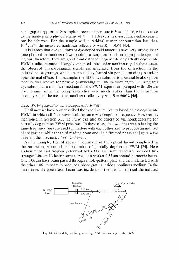
As an example, Fig. 14 shows a schematic of the optical layout, employed inthe earliest experimental demonstration of partially degenerate FWM [24]. Herea Q-switched and frequency-doubled Nd:YAG laser simultaneously provided twostronger 1.06 mm IR laser beams as well as a weaker 0.53 mm second-harmonic beam.One 1.06 mm laser beam passed through a hole-pattern plate and then interacted withthe other 1.06 mm beam to produce a phase grating inside a nonlinear medium. In themean time, the green laser beam was incident on the medium to read the induced
Nd:YAGLaser
FrequencyDoubler
Optical Delay
1.06 µm
0.53 µm
0.53
µm
0.53 µm
1.06 µm
1.06
µm
(1)
(2)
(3)
(4)
Hole Pattern
Fig. 14. Optical layout for generating PCW via nondegenerate FWM.
G.S. He / Progress in Quantum Electronics 26 (2002) 131–191156
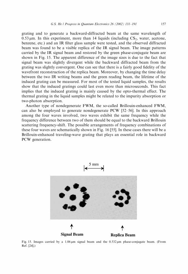
grating and to generate a backward-diffracted beam at the same wavelength of0.53 mm. In this experiment, more than 14 liquids (including CS2, water, acetone,benzene, etc.) and an IR filter glass sample were tested, and the observed diffractedbeam was found to be a visible replica of the IR signal beam. The image patternscarried by the IR signal beam and restored by the green phase-conjugate beam areshown in Fig. 15. The apparent difference of the image sizes is due to the fact thatsignal beam was slightly divergent while the backward diffracted beam from thegrating was slightly convergent. One can see that there is a fairly good fidelity of thewavefront reconstruction of the replica beam. Moreover, by changing the time delaybetween the two IR writing beams and the green reading beam, the lifetime of theinduced grating can be measured. For most of the tested liquid samples, the resultsshow that the induced gratings could last even more than microseconds. This factimplies that the induced grating is mainly caused by the opto-thermal effect. Thethermal grating in the liquid samples might be related to the impurity absorption ortwo-photon absorption.
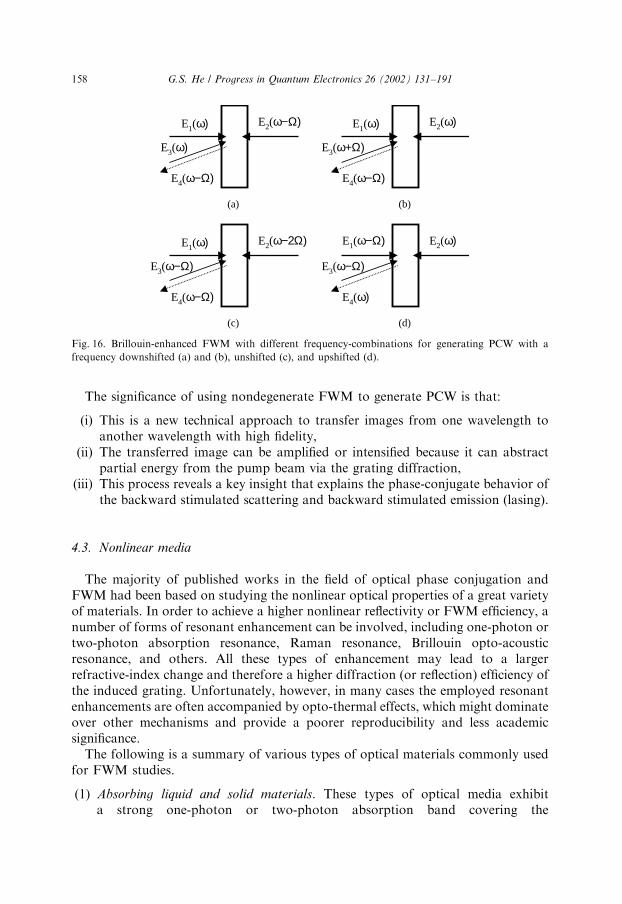
Another type of nondegenerate FWM, the so-called Brillouin-enhanced FWM,can also be employed to generate nondegenerate PCW [52–56]. In this approachamong the four waves involved, two waves exhibit the same frequency while thefrequency difference between two of them should be equal to the backward Brillouinscattering frequency-shift. The possible arrangements of frequency combinations ofthese four waves are schematically shown in Fig. 16 [55]. In these cases there will be aBrillouin-enhanced traveling-wave grating that plays an essential role in backwardPCW generation.
Fig. 15. Images carried by a 1.06mm signal beam and the 0.532mm phase-conjugate beam. (From
Ref. [24].)
G.S. He / Progress in Quantum Electronics 26 (2002) 131–191 157
The significance of using nondegenerate FWM to generate PCW is that:
(i) This is a new technical approach to transfer images from one wavelength toanother wavelength with high fidelity,
(ii) The transferred image can be amplified or intensified because it can abstractpartial energy from the pump beam via the grating diffraction,
(iii) This process reveals a key insight that explains the phase-conjugate behavior ofthe backward stimulated scattering and backward stimulated emission (lasing).
4.3. Nonlinear media
The majority of published works in the field of optical phase conjugation andFWM had been based on studying the nonlinear optical properties of a great varietyof materials. In order to achieve a higher nonlinear reflectivity or FWM efficiency, anumber of forms of resonant enhancement can be involved, including one-photon ortwo-photon absorption resonance, Raman resonance, Brillouin opto-acousticresonance, and others. All these types of enhancement may lead to a largerrefractive-index change and therefore a higher diffraction (or reflection) efficiency ofthe induced grating. Unfortunately, however, in many cases the employed resonantenhancements are often accompanied by opto-thermal effects, which might dominateover other mechanisms and provide a poorer reproducibility and less academicsignificance.
The following is a summary of various types of optical materials commonly usedfor FWM studies.
(1) Absorbing liquid and solid materials. These types of optical media exhibita strong one-photon or two-photon absorption band covering the
E4(ω−Ω)
E2(ω−Ω)
E3(ω)
E1(ω)
E4(ω−Ω)
E2(ω−2Ω)
E3(ω−Ω)
E1(ω)
E4(ω−Ω)
E2(ω)
E3(ω+Ω)
E1(ω)
E4(ω)
E2(ω)
E3(ω−Ω)
E1(ω−Ω)
(a)
(c)
(b)
(d)
Fig. 16. Brillouin-enhanced FWM with different frequency-combinations for generating PCW with a
frequency downshifted (a) and (b), unshifted (c), and upshifted (d).
G.S. He / Progress in Quantum Electronics 26 (2002) 131–191158
wavelength range of employed laser beams. In most cases the majormechanism causing the induced refractive-index change is eitherpopulation change or related opto-thermal effect. The typical materialsin this category include dye solutions [57–61] or dye-dopedmatrixes [62–68], impurity-doped glasses [69–75] and crystals [76–79],fullerenes (e.g. C60) related materials [80–82], and liquid crystals[83–86].
(2) Lasing (gain) media. Degenerate FWM and phase-conjugation experimentscan be achieved in various pumped lasing media, such as Nd:YAG andothers [87–92]. In those cases the three incident beams exhibit the samewavelength, i.e. the lasing wavelength of a given gain medium (e.g.1064 nm for Nd:YAG). One of the major mechanisms producinginduced gratings could be the periodic spatial modulation of populationdistribution in the medium. The advantage of using lasing media as FWMmaterials might be that the phase-conjugate signal could get additionalstimulated amplification through the population inversion systems. Thereported nonlinear reflectivity could be up to B2500 for a small signal intensityand multi-pass geometry [88].
(3) Metal vapors. Degenerate or near degenerate FWM can be efficientlyaccomplished in various metal vapors, including Na, K, Rb, Cs, and others[93–99]. Compared with liquid or solid absorbing media, metal atoms in thevapor phase exhibit much narrower absorption line width, therefore thewavelengths of incident laser beams have to be tuned close enough to the chosenspectral transition to reach the necessary resonant enhancement. The reportednonlinear reflectivity can be as high as B300 [100].
(4) Photorefractive materials. Degenerate FWM is a common technique toinvestigate the optical phase conjugation properties of photorefractivematerials. It is well known that the photorefractive effect is based on thecombination of photoconductivity-induced charge separation and sub-sequent electro-optic response in a second-order nonlinear medium [101–103].In this sense the mechanisms of induced refractive-index change aretotally different from the above mentioned third-order nonlinear media. Forthis reason most photorefractive materials used for FWM and phaseconjugation studies are impurity-doped inorganic crystals, such asLiNbO3, LiTaO3, BaTiO3, KNbO3, Sr1xBaxNb2O6 (SBN), Ba2xSrxK1y
NayNb5O15 (KNSBN), Bi12(Si, Ge)O20, KH2PO4, CdS, GaAs, InP,etc. [104]. In the recent decade, organic crystals and dc-field poledpolymer materials have also been employed as novel photorefractivematerials for FWM studies [105]. Generally speaking, photorefractive materialscan provide a high efficiency light-induced gratings even when using low powercw laser beams in OPC experiments [106,107]. The main disadvantage of thistype of nonlinear material for FWM performances is their slow temporalresponse (usually in 1–103 s range). The details of utilizing photorefractivematerials to generate optical phase conjugate waves (PCW) are beyond thescope of this review.
G.S. He / Progress in Quantum Electronics 26 (2002) 131–191 159

5. PCW generation via backward stimulated scattering
To date, one of the most simple and efficient methods to generate backward PCWis based on various backward stimulated scattering processes, in particular,stimulated Brillouin scattering. In this approach, only a strong and single focusedlaser beam is needed to pump a given scattering medium, and the backwardstimulated scattering beam can be automatically phase-conjugated with the inputpump beam, under appropriate experimental conditions. To interpret this specialproperty of the backward stimulated scattering, a quasi-collinear and nondegenerateFWM model can be employed, which may give a clear and straightforwardexplanation on this property in both qualitative and quantitative ways.
5.1. Phase-conjugation properties of backward stimulated scattering
The earliest observation of the optical phase conjugation effect was made in anexperiment of stimulated Brillouin scattering (SBS) in 1972 by Zel’dovich et al. [11]The experimental arrangement used for this type of observation is shownschematically in Fig. 17. Here, the pump source was a single-axial-mode and Q-switched ruby laser; the pump beam was passed through an aberration plate andthen focused onto the scattering medium. After passing back through the sameaberration plate, the spatial structure of the backward SBS could be compared tothat of the incident pump beam. In the experiment, the scattering medium was high-pressure CF6 gas filling in a 94 cm long cell, the divergence of the input l0 ¼ 694:3-nm pump beam was 0.14 1.3 mrad, and after passing through the aberration plateit became B3.5 mrad. If a plane mirror was put in the path of the pump beam andthe reflected pump beam was allowed to pass through the aberrator a second time,the beam divergence was increased to B6.5 mrad. Whereas, it was shown that afterpassing through the same aberrator the backward SBS had nearly the samedivergence as the initial pump beam, i.e., the aberration influence was removed. Themeasured energy-transfer efficiency from the input pump pulse to the backward SBSpulse was ZE25% [11]. In another similar early experiment, the scattering mediumwas CS2 liquid in a glass cell and the aberration plate was replaced by a poor-qualityruby amplifier rod. The divergence of the initial input pump beam was 0.13 mrad;
Laser Aberrator Lens
Scattering MediumBackward
SBS Output ωB
Pump Input ω0 ω0
ωB
Fig. 17. Experimental arrangement for observing phase-conjugation behavior of backward stimulated
Brillouin scattering.
G.S. He / Progress in Quantum Electronics 26 (2002) 131–191160

after passing through the amplifier rod it increased to 2.5 mrad. In contrast, afterpassing through the same amplifier rod the backward SBS exhibited a divergenceangle of only B0.15 mrad, and the measured energy transfer efficiency wasZE60% [12].
The results of these two experiments showed that the aberration influence imposedon an input pump laser beam could be automatically canceled in the backward SBSbeam. In this sense the backward SBS beam is a phase-conjugate wave of the inputpump beam. However, during that time period this observation could not be wellexplained by the known theory of SBS. For this reason, the results did not attractmuch attention in research community for more than 4–5 years until 1977, when thetheories of phase-conjugate wave generation via three-wave and four-wave mixingwere suggested [17,9] and experimentally proven [18,10]. Since then studies of PCWgeneration via backward-stimulated scattering have become more interesting forresearchers because of its simplicity and high efficiency.
More importantly, it was found that the PCW could be generated not only by thebackward stimulated Brillouin (SBS) process [108–119], but also by other stimulatedscattering processes, such as the backward stimulated Raman scattering (SRS) [120–125], stimulated Rayleigh-wing scattering (SRWS) [126–128], and the so-called self-pumped backward stimulated scattering in photorefractive materials [129–134]. Herewe shall describe several experimental results that clearly demonstrate the phase-conjugate properties of backward stimulated-scattering beams generated throughdifferent scattering mechanisms.
Fig. 18 shows the intensity distributions and photographs of far-field patterns ofthe original pump beam, the aberrated pump beam, and the aberration-correctedbackward SBS beam from CS2 liquid [108]. The pump beam was a TEM00 singlelongitudinal-mode 694.3 nm pulsed laser beam of 17 ns duration with B0.57 mrad
Fig. 18. Normalized far-filed intensity distributions and photographs for the original pump beam, the
aberrated pump beam, and the aberration-corrected backward SBS beam. (From Ref. [108].)
G.S. He / Progress in Quantum Electronics 26 (2002) 131–191 161
divergence angle. After twice passing through an aberrator (a microscope slideetched in hydrofluoric acid), the divergence angle of the pump beam was increased to6.6 mrad. In contrast, after passing through the same aberrator the backward SBSbeam exhibited a much smaller angle of 0.44 mrad; in other words, the aberrationwas totally corrected.
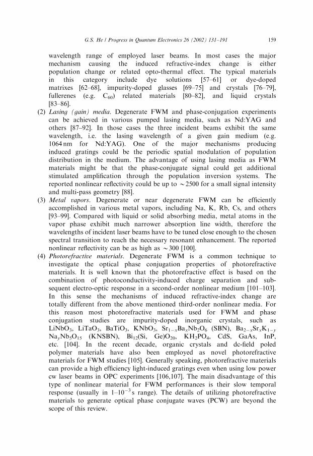
As another example, Fig. 19 shows the image-reconstruction by a backwardstimulated Rayleigh-wing scattering (SRWS) beam from a CS2-liquid cell pumpedwith linearly polarized 532 nm laser pulses of 20 ps pulse duration and 15 mJ energy[128]. From Fig. 19 one can see that the influence from the aberrator can to someextent be (not perfectly) removed from the backward SRWS beam.
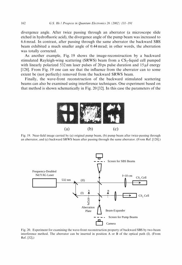
Finally, the wave-front reconstruction of the backward stimulated scatteringbeams can also be examined using interference techniques. One experiment based onthat method is shown schematically in Fig. 20 [32]. In this case the parameters of the
Fig. 19. Near-field image carried by (a) original pump beam, (b) pump beam after twice-passing through
an aberrator, and (c) backward SRWS beam after passing through the same aberrator. (From Ref. [128].)
Frequency-DoubledNd:YAG Laser
Camera
Screen for Pump Beams
Beam-Expander
CS2 Cell
CS2 Cell
A B
532 nm (II)
(I)
Screen for SBS Beams
Aberration Plate
f=10 cm
Fig. 20. Experiment for examining the wave-front reconstruction property of backward SBS by two-beam
interference method. The aberrator can be inserted in position A or B of the optical path (I). (From
Ref. [32].)
G.S. He / Progress in Quantum Electronics 26 (2002) 131–191162
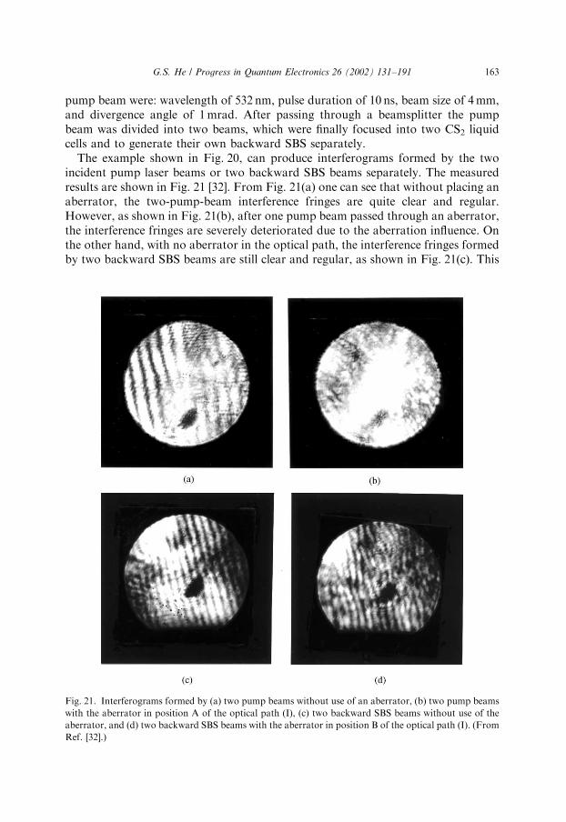
pump beam were: wavelength of 532 nm, pulse duration of 10 ns, beam size of 4 mm,and divergence angle of 1 mrad. After passing through a beamsplitter the pumpbeam was divided into two beams, which were finally focused into two CS2 liquidcells and to generate their own backward SBS separately.
The example shown in Fig. 20, can produce interferograms formed by the twoincident pump laser beams or two backward SBS beams separately. The measuredresults are shown in Fig. 21 [32]. From Fig. 21(a) one can see that without placing anaberrator, the two-pump-beam interference fringes are quite clear and regular.However, as shown in Fig. 21(b), after one pump beam passed through an aberrator,the interference fringes are severely deteriorated due to the aberration influence. Onthe other hand, with no aberrator in the optical path, the interference fringes formedby two backward SBS beams are still clear and regular, as shown in Fig. 21(c). This
Fig. 21. Interferograms formed by (a) two pump beams without use of an aberrator, (b) two pump beams
with the aberrator in position A of the optical path (I), (c) two backward SBS beams without use of the
aberrator, and (d) two backward SBS beams with the aberrator in position B of the optical path (I). (From
Ref. [32].)
G.S. He / Progress in Quantum Electronics 26 (2002) 131–191 163

implies that the two backward SBS beams were good replicas of the two pumpbeams when there was no induced aberration influence. If an aberrator is put in theposition B of the optical path (I), the quality of the interference fringes formed bytwo SBS beams is still fairly good as shown in Fig. 21(d). This is further experimentalevidence demonstrating the aberration-correction capability of backward stimulatedscattering.
Considering the experimental results described above, we can generally concludethat (i) without or under small aberration influence, the backward stimulatedscattering beam can be a nearly perfect replica of the incident pump beam; (ii) undera larger aberration influence the backward stimulated scattering beam can only be anapproximate replica of the pump beam. The fidelity of the reconstructed wave frontof a backward stimulated scattering beam is determined by many experimentalfactors, such as the pump intensity level, pump focusing geometry, gain length, typeof scattering medium, type of scattering mechanism, frequency-shift range, and theextent of aberration.
5.2. Theoretical explanations: quasi-collinear and nondegenerate FWM model
Though various types of backward stimulated scattering (BSS) can readily beutilized to efficiently generate optical phase-conjugate waves, it has taken quite along time for researchers to understand the substance of these processes and to give aclear physical explanation without invoking cumbersome mathematical treatments.
A considerable number of the early theoretical papers were published (see, forexample, Refs. [2], [135–143] and references therein). Many were based on aphenomenological assumption that there is an exponential gain discrimination (in afactor of 2) between the phase-conjugate portion and non-phase-conjugate portionof BSS; as a result, only the former could get the maximum gain and be effectivelyamplified in the scattering medium. However, for a long time, there was a lack of aclear theoretical model or physical mechanism to support this assumption. Evenignoring the confusion and discrepancies among some of these papers, mosttheoretical analyses could not answer a key question: why could only the phase-conjugate portion of the BSS finally become the predominant output? For instance,on the one hand it is known that higher pump intensity is needed to have a betterphase-conjugation fidelity for backward stimulated scattering. On the other hand,however, gain saturation will take place under these circumstances; as a result thegain difference between these two portions should be getting smaller, and a worsephase-conjugate fidelity would be expected according to the phenomenologicalassumption mentioned above. In some existing theoretical analyses both the pumpfield and BSS field were represented by an infinite series function. In those cases itwas extremely difficult to obtain explicit analytical solutions for the nonlinear waveequations.
In addition, we know well that the principle of using degenerate or nondegenerateFWM to produce optical phase-conjugate waves (PCW) is based on the wave-frontreconstruction by induced holographic gratings in the nonlinear medium. However,it is also known that the phase-conjugate waves can also be generated from various
G.S. He / Progress in Quantum Electronics 26 (2002) 131–191164
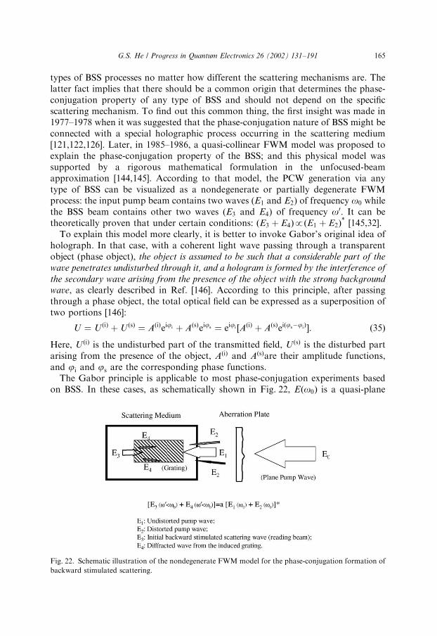
types of BSS processes no matter how different the scattering mechanisms are. Thelatter fact implies that there should be a common origin that determines the phase-conjugation property of any type of BSS and should not depend on the specificscattering mechanism. To find out this common thing, the first insight was made in1977–1978 when it was suggested that the phase-conjugation nature of BSS might beconnected with a special holographic process occurring in the scattering medium[121,122,126]. Later, in 1985–1986, a quasi-collinear FWM model was proposed toexplain the phase-conjugation property of the BSS; and this physical model wassupported by a rigorous mathematical formulation in the unfocused-beamapproximation [144,145]. According to that model, the PCW generation via anytype of BSS can be visualized as a nondegenerate or partially degenerate FWMprocess: the input pump beam contains two waves (E1 and E2) of frequency o0 whilethe BSS beam contains other two waves (E3 and E4) of frequency o0: It can betheoretically proven that under certain conditions: ðE3 þ E4ÞpðE1 þ E2Þ
[145,32].To explain this model more clearly, it is better to invoke Gabor’s original idea of
holograph. In that case, with a coherent light wave passing through a transparentobject (phase object), the object is assumed to be such that a considerable part of the
wave penetrates undisturbed through it, and a hologram is formed by the interference of
the secondary wave arising from the presence of the object with the strong background
wave, as clearly described in Ref. [146]. According to this principle, after passingthrough a phase object, the total optical field can be expressed as a superposition oftwo portions [146]:
U ¼ U ðiÞ þ U ðsÞ ¼ AðiÞeiji þ AðsÞeijs ¼ eiji ½AðiÞ þ AðsÞeiðjsjiÞ: ð35Þ
Here, U ðiÞ is the undisturbed part of the transmitted field, U ðsÞ is the disturbed partarising from the presence of the object, AðiÞ and AðsÞare their amplitude functions,and ji and js are the corresponding phase functions.
The Gabor principle is applicable to most phase-conjugation experiments basedon BSS. In these cases, as schematically shown in Fig. 22, Eðo0Þ is a quasi-plane
Fig. 22. Schematic illustration of the nondegenerate FWM model for the phase-conjugation formation of
backward stimulated scattering.
G.S. He / Progress in Quantum Electronics 26 (2002) 131–191 165

pump wave. After passing through an aberration plate or a phase subject, the pumpfield manifests itself as a superposition of two portions: a stronger undisturbed waveE1ðo0Þ and a weaker distorted wave E2ðo0Þ: These two waves interfere with eachother in a scattering (gain) medium and create an induced volume holographicgrating due to intensity-dependent refractive index changes of the medium. Only theundisturbed pump wave E1ðo0Þ is strong enough to fulfill the threshold requirementand to generate an initial BSS wave E3ðo0Þ that exhibits a regular wavefront as waveE1ðo0Þ: When wave E3ðo0Þ passes back through the induced holographic gratingregion, a diffracted wave E4ðo0Þ can be created. Here we see a typical holographicwavefront-reconstruction process: the induced grating is formed by the regularE1ðo0Þ wave (reference beam) and the irregular E2ðo0Þ wave (signal beam), the initialbackward stimulated scattering E3ðo0Þ is a reading beam with a regular wavefront,and the diffracted wave E4ðo0Þ will be the phase-conjugate replica of the E2ðo0Þwave.
Moreover, the wave E4ðo0Þ will experience an amplification with the wave E3ðo0Þtogether because both waves have the same scattering frequency. In the case ofstimulated Brillouin scattering, o0Eo0; it is a nearly degenerate quasi-collinearFWM process. In the case of stimulated Raman scattering, o0 > o0; there is apartially degenerate and frequency down-converted FWM process. In the case ofanti-Stokes stimulated scattering, o0oo0; there is a partially degenerate andfrequency up-converted FWM process. Based on the explanation described above,one can see a common mechanism (pump field-induced holographic grating) playsthe same role for phase-conjugation formation by using either FWM or BSS method.This common mechanism is applicable to all types of backward stimulated scatteringprocesses including stimulated Brillouin, Raman, Rayleigh-wing, Kerr and otherscattering, even though the specific scattering mechanisms can be totally different foreach other.
Although there is a common ground for PCW generation via conventional FWMor BSS, there is still a remarkable difference between these two processes. For theformer, only two waves (the signal wave and the backward diffracted wave) arephase-conjugate to each other; however, for the latter, the sum of the two portions ofthe BSS beam should be phase-conjugated to the sum of the two portions of theinput pump beam. In the next subsection it can be mathematically proven that thelatter situation can indeed be realized [145].
5.3. Mathematical treatment in unfocused-beam approximation
According to the proposed quasi-collinear and partially degenerate FWM modelof the BSS process, after passing through an aberration plate the total input pumpfield can be expressed by the sum of two portions:
Epðo; zÞ ¼ ½A1ðzÞ þ A2ðzÞeiyðzÞeiðotþkzÞ: ð36Þ
Here, A1 and A2 are the real amplitude functions of the undistorted portion andthe distorted portion of the pump field, y is a phase change function, the pump fieldis propagating in the z direction, and k is the magnitude of the wave vector. For
G.S. He / Progress in Quantum Electronics 26 (2002) 131–191166
simplicity, we assume that the original input pump field is an ideal monochromaticand uniform plane wave before passing through the aberration plate. Thus A1 andA2 are only the functions of z. Here y represents the deviation of wavefront of thedistorted portion from an ideal plane wavefront.
Based on the picture illustrated in Fig. 22, the total backward stimulatedscattering field can also be expressed by a sum of two portions:
E 0ðo0; zÞ ¼ ½A01ðzÞ þ A0
2ðzÞeiy0ðzÞeiðo0tk0zÞ: ð37Þ
Here, A01 is a real amplitude function of the initial BSS wave (reading beam), A0
2 is areal amplitude function of the diffracted wave through FWM or grating diffraction,and y0 is the relative phase change function between the A0
1 and A02 waves. In Eq. (37)
it is assumed that the initial backward stimulated scattering is also an ideal planewave; this assumption is supported by experimental results without using anaberration plate. In the steady-state condition, A1; A2; y and A0
1; A02; y0 are
independent of time t:In a small-signal approximation, the initial BSS wave experiences an exponential
gain described by
A01ðzÞ ¼ A0
1ð0ÞegA2
1z=2; ð38Þ
where g is the exponential gain factor due to stimulated amplification from thescattering system.
As a result of interaction among the three waves of A1; A2 and A01; the fourth wave
of A02 can be generated through the mechanism of FWM or grating diffraction, and it
will get the further stimulated-scattering amplification as A01 does. The wave
equation obeyed by the diffracted wave of E02 ¼ A0
2 eiy0ðzÞ eiðo0tk0zÞ can be written as
r2E 02
n20ðo
0Þc2
q2E02
qt2¼ m0
q2Pð3Þ2
qt2; ð39Þ
where n0 is the linear refractive index, m0 is the permeability of free space, and Pð3Þ2 is
the third-order nonlinear polarization contribution to the wave E02; which can be
expressed as
Pð3Þ2 ¼ e0w0ð3Þe A1A0
1A2 eiyðzÞeiðo0tk0zÞ: ð40Þ
Here, w0ð3Þe is a formally introduced effective third-order nonlinear susceptibilityvalue. If we only consider the gain behavior of the amplitude A0
2; w0ð3Þe can be viewed
as a pure imaginary quantity, i.e. w0ð3Þe ¼ iw00ð3Þe ; where w00ð3Þe is a real quantity.Substituting Eq. (40) into Eq. (39) and using slowly varying amplitude approxima-tion leads to
qA02
qzþ
A02
2k0r2y0 ¼
k0w00ð3Þe
2A1A2A0
1cos dy;
qy0
qzþ
1
2k0 ðry0Þ2 ¼k0w00ð3Þe
2A1A2A0
1
1
A02
sin dy;ð41Þ
where
dy ¼ y y0: ð42Þ
G.S. He / Progress in Quantum Electronics 26 (2002) 131–191 167
In the small aberration approximation and under the high single-path gaincondition, i.e.
gA21zb1; ð43Þ
one can finally obtain the following approximate solutions:
A02ðzÞ ¼
A2
A1A0
1ðzÞ ¼A2
A1A0
1ð0ÞegA2
1z=2;
dyðzÞ ¼ yðzÞ y0ðzÞ ) 0; ð44Þ
The physical meaning of the second equation above is that while the wave A02ðzÞ is
getting stronger through the exponential gain, its wavefront is getting closer to thewavefront of the wave A2:
Based on Eqs. (37), (38) and (44), the final solution of the total backwardstimulated scattering field is
E 0 ¼A0
1ð0ÞA1
egA21z=2½A1 þ A2 eiyðzÞeiðo0tk0zÞ: ð45Þ
Comparing this expression with the following expression for the total input pumpfield
Ep ¼ ½A1 þ A2 eiyðzÞeiðotþkzÞ; ð46Þ
we see that the output backward stimulated scattering field can be a phase-conjugatereplica of the input pump field, provided that the high gain condition of Eq. (43) issatisfied. In practice, this requirement can be achieved by increasing either theeffective gain length or the pump intensity level.
It should be pointed out that the theoretical treatment described above is based onthe small-aberration influence. Experimental results have shown that under a smallaberration influence, the output backward stimulated scattering can be a goodphase-conjugate wave of the input pump field.
So far, we have not considered the influence of the difference between o and o0 orbetween k and k0 on the phase-conjugation property of the BSS beam. This influenceresembles that a case when someone creates a hologram with two beams of frequencyo and then reads this hologram with another beam of frequency o0: In this case thesize or position of the reconstructed image might be slightly changed.
Finally, the aforesaid theoretical treatment is based on the near-plane waveapproximation. However, in most experiments, the pump beams are focused into thescattering medium. In that case we should invoke the Hermite–Gaussian beamapproximation, and the mathematical treatment will be somewhat lengthy [32].Nevertheless, similar conclusions can be reached for the circumstance of a focusedpump field, and the high gain of stimulated scattering is still the basic requirement.However, in this case it can be derived that a nearly perfect phase-conjugate wavecan only be obtained for the small aberration influence; under the larger aberrationinfluence the fidelity of wavefront reconstruction of the BSS beam will deteriorate.
G.S. He / Progress in Quantum Electronics 26 (2002) 131–191168
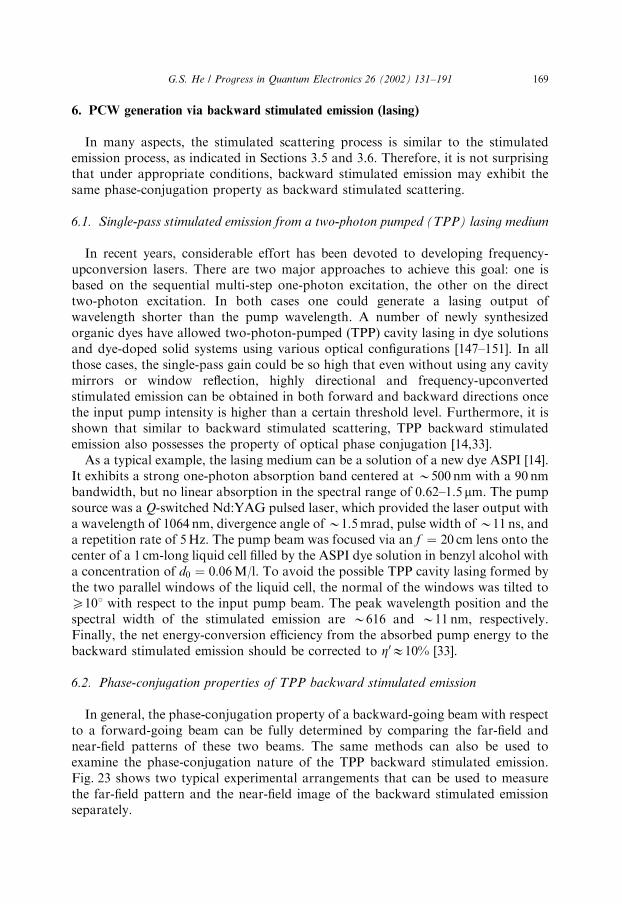
6. PCW generation via backward stimulated emission (lasing)
In many aspects, the stimulated scattering process is similar to the stimulatedemission process, as indicated in Sections 3.5 and 3.6. Therefore, it is not surprisingthat under appropriate conditions, backward stimulated emission may exhibit thesame phase-conjugation property as backward stimulated scattering.
6.1. Single-pass stimulated emission from a two-photon pumped (TPP) lasing medium
In recent years, considerable effort has been devoted to developing frequency-upconversion lasers. There are two major approaches to achieve this goal: one isbased on the sequential multi-step one-photon excitation, the other on the directtwo-photon excitation. In both cases one could generate a lasing output ofwavelength shorter than the pump wavelength. A number of newly synthesizedorganic dyes have allowed two-photon-pumped (TPP) cavity lasing in dye solutionsand dye-doped solid systems using various optical configurations [147–151]. In allthose cases, the single-pass gain could be so high that even without using any cavitymirrors or window reflection, highly directional and frequency-upconvertedstimulated emission can be obtained in both forward and backward directions oncethe input pump intensity is higher than a certain threshold level. Furthermore, it isshown that similar to backward stimulated scattering, TPP backward stimulatedemission also possesses the property of optical phase conjugation [14,33].
As a typical example, the lasing medium can be a solution of a new dye ASPI [14].It exhibits a strong one-photon absorption band centered at B500 nm with a 90 nmbandwidth, but no linear absorption in the spectral range of 0.62–1.5 mm. The pumpsource was a Q-switched Nd:YAG pulsed laser, which provided the laser output witha wavelength of 1064 nm, divergence angle of B1.5 mrad, pulse width of B11 ns, anda repetition rate of 5 Hz. The pump beam was focused via an f ¼ 20 cm lens onto thecenter of a 1 cm-long liquid cell filled by the ASPI dye solution in benzyl alcohol witha concentration of d0 ¼ 0:06 M/l. To avoid the possible TPP cavity lasing formed bythe two parallel windows of the liquid cell, the normal of the windows was tilted toX101 with respect to the input pump beam. The peak wavelength position and thespectral width of the stimulated emission are B616 and B11 nm, respectively.Finally, the net energy-conversion efficiency from the absorbed pump energy to thebackward stimulated emission should be corrected to Z0E10% [33].
6.2. Phase-conjugation properties of TPP backward stimulated emission
In general, the phase-conjugation property of a backward-going beam with respectto a forward-going beam can be fully determined by comparing the far-field andnear-field patterns of these two beams. The same methods can also be used toexamine the phase-conjugation nature of the TPP backward stimulated emission.Fig. 23 shows two typical experimental arrangements that can be used to measurethe far-field pattern and the near-field image of the backward stimulated emissionseparately.
G.S. He / Progress in Quantum Electronics 26 (2002) 131–191 169

In the case shown in Fig. 23(a), an aberration plate was placed in front of anf ¼ 20 cm focusing lens. The backward stimulated emission was recollimated by thesame f ¼ 20 cm lens, passed through the aberration plate, and then focused via anf ¼ 50 cm lens onto a display screen. In this way, the far-field distribution of thebackward stimulated emission can be measured and recorded with a digital CCDcamera.
In another case (shown in Fig. 23(b)), the dye solution cell was a glass vial. In thiscase the glass wall of the vial itself played the role of aberration plate. Todemonstrate the image-reconstruction ability of the backward stimulated emission, aletter-printed plate, made by printing a black letter of 10 mm size on a transparentfilm, was placed between the beam splitter and the beam expander. If the backward
CuvetteSample f=20 cm
Aberration plate
f=50 cmScreen
f=5 cm
Nd:YAG laser
Camera
Beamsplitter
Nd:YAG laser
Letter plateVialSample
(a)
(b)
1064 nm
~616 nm
1064 nm
~616 nm
f=30 cm
Camera
Beamsplitter
Screen
Fig. 23. Experiment for demonstrating phase-conjugation properties of the TPP backward stimulated
emission: (a) configuration for the far-field measurement and (b) configuration for the near-field image
measurement.
G.S. He / Progress in Quantum Electronics 26 (2002) 131–191170

stimulated emission had the phase-conjugate nature, a clear image of the letter plateshould be observed on the screen.
In an experimental arrangement as shown in Fig. 23(a), the measured divergenceangles (FWHM) for the pump beam, forward stimulated emission and backwardstimulated emission were B0.25, 0.23, and 0.23 mrad, respectively, without insertionof an aberration plate. The corresponding far-field distributions for these threebeams are shown in Fig. 24(a).
To test the aberration-compensation capability of backward stimulated emission,an aberration plate was inserted in the path of the input pump beam, which was aglass slide etched by hydrofluoric acid solution, and could cause either a 0.8–0.9 mrad irregular aberration influence by one pass or a 1.6–1.8 mrad aberrationinfluence by two passes. The results under this condition are shown in Fig. 24(b).These results show that, after passing back through the aberration plate, theaberration influence is almost entirely removed from the backward stimulated
Fig. 24. Normalized far-field intensity distributions for the input pump beam (upper), the backward
stimulated emission beam (middle), and the forward stimulated emission beam (bottom): (a) without
placing an aberrator and (b) with placing an aberrator. The display resolution is B0.07 mm or
B0.13 mrad. (From Ref. [14].)
G.S. He / Progress in Quantum Electronics 26 (2002) 131–191 171

emission; whereas there is a remarkable aberration influence remaining in the bottomregions of the far-field profile for forward stimulated emission.
A similar experiment was carried out based on the setup shown in Fig. 23(a), withno aberrator in place but, replacing the dye solution-filled cuvette with a dye-solution-filled glass vial, so that the glass wall of the vial played the role of anaberration plate. Fig. 25(a) shows the resultant far-field pattern of the originalincident 1064 nm-pump beam with a divergence angle of B0.25 mrad. Fig. 25(b)shows the far-field pattern of the transmitted pump beam after passing through aglass vial filled with pure solvent (benzyl alcohol). The beam divergence angle isincreased to 0.7 1.2 mrad, and the unsymmetrical distribution of the aberratedpattern was due to the quasi-cylindrical shape of the wall of the glass vial. Fig. 25(c)shows the far-field distribution of the TPP backward stimulated emission from anASPI solution-filled vial at a pump level of 1.7 mJ, where the beam divergence angleof the backward stimulated emission is B0.25 mrad and the aberration influencefrom the vial’s wall is almost completely removed. Lastly, Fig. 25(d) shows the far-field distribution of the forward stimulated emission from the same ASPI solution-
Fig. 25. Normalized far-field profiles for (a) the input 1064 nm pump beam, (b) the transmitted pump
beam through a glass vial filled with pure solvent, (c) the backward B616mm stimulated emission, and (d)
the forward stimulated emission from a dye-solution filled glass vial. Here 1-mm dimension corresponds to
2 mrad divergence angle. (From Ref. [33].)
G.S. He / Progress in Quantum Electronics 26 (2002) 131–191172

filled vial at the same pump level of 1.7 mJ, where the severe aberration influence israther obvious.
Another important feature is that the original image carried by the input pumpfield can be reconstructed by the backward stimulated emission beam after passingthrough the aberrator or a disturbing medium. To demonstrate this feature, theexperimental setup shown in Fig. 23(b) was employed. In that case, a letter-printedtransparent film was placed between the f ¼ 30 cm lens and the beam splitter, andthe gain sample was the same ASPI solution-filled glass vial. After reflection from thebeam splitter, the collimated TPP backward stimulated emission was directlyprojected onto a paper screen, and then the image message recorded with anordinary camera.
Fig. 26(a) shows a photograph of the incident 1064 nm pump beam after passingthrough the letter plate. This image is obtained by illuminating the pump beam on anIR sensor card. Fig. 26(e) shows a photograph of the forward upconvertedstimulated emission collimated via an f ¼ 20 cm lens, the original image messageis totally lost owing to the influence of aberration from the vial wall. Fig. 26(f) showsa photograph of the backward stimulated emission of B616 nm wavelength, whereone can see that the original image is basically reconstructed by the backwardstimulated emission after passing through the vial wall.
To compare the capability of image reconstruction for the backward stimulatedemission with that for the backward stimulated scattering, Fig. 26(b) shows aphotograph of the backward SBS from an acetone-filled glass vial. In this case, theexperimental setup was the same except that the 1064-nm pump beam was replacedby a frequency-doubled Nd:YAG laser beam of 532 nm wavelength. In addition,Figs. 26(c) and (d) show the forward- and backward SRS from a benzene-filled vialat the first-order Stokes wavelength of the 992 cm1 Raman mode pumped with thesame 532 nm laser beam. Once again, only the backward stimulated scattering showsthe image restoration capability. From that comparison one can see that these threemethods have shown nearly the same near-field restoration performance under theexperimental conditions described above [33].
6.3. Explanations for the phase-conjugation nature of backward stimulated emission
The appropriate experimental conditions for generating backward single-passstimulated emission can be summarized (i) the pump beam should be a focused laserbeam, (ii) there should be a high single-pass gain in the gain medium, (iii) theinteraction length should be much longer than the beam size, and (iv) the aberrationinfluence should not be too large. Based on these considerations, one may realizethat the physical model and theoretical treatment used to explain the phase-conjugation property of the backward stimulated scattering are also applicable to thecase of backward stimulated emission [34].
The starting point is still the Gabor principle or the associated quasi-collinear andnondegenerate (or partially degenerate) FWM process occurring in a TPP lasingmedium. This process is schematically shown in Fig. 27. Here, E0ðoÞ is a quasi-planepump wave, and after passing through an aberration plate or a disturbing medium, it
G.S. He / Progress in Quantum Electronics 26 (2002) 131–191 173

manifests itself as a superposition of two portions: a stronger, undisturbed waveE1ðoÞ and a weak and distorted wave E2ðoÞ: After further passing through afocusing lens, these two waves interfere with each other in the focal region inside thegain medium and create an induced volume holographic grating. Only the waveE1ðoÞ is strong enough to fulfill the threshold requirement and to generate an initialbackward stimulated emission wave E3ðo0Þ at a new wavelength. As the E3ðo0Þ wavebackward passes through the induced-holographic grating region, a diffractedwave E4ðo0Þ is created, which will be the phase-conjugate replica of the waveE2ðoÞ and undergo further amplification together with the wave E3ðo0Þ: In the caseof two-photon excited stimulated emission, ooo0, there is a partially degenerateand frequency-upconverted FWM process. It can be theoretically proven thatunder appropriate conditions, the total backward field (E3 þ E4) can be the
Fig. 26. Near-field images carried by (a) 532 nm (or 1064 nm) input pump beam, (b) the backward
stimulated Brillouin scattering from an acetone-filled vial, (c) and (d) the forward and backward
stimulated Raman scattering from a benzene-filled vial, (e) and (f) the forward and backward two-photon
pumped stimulated emission from an ASPI dye solution-filled vial. (From Ref. [33].)
G.S. He / Progress in Quantum Electronics 26 (2002) 131–191174
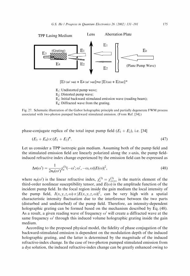
phase-conjugate replica of the total input pump field (E1 þ E2), i.e. [34]
ðE3 þ E4ÞpðE1 þ E2Þn: ð47Þ
Let us consider a TPP isotropic gain medium. Assuming both of the pump field andthe stimulated emission field are linearly polarized along the x-axis, the pump field-induced refractive index change experienced by the emission field can be expressed as
Dnðo0Þ ¼1
2n0ðo0Þwð3Þe ðo0;o0;o;oÞ EðoÞj j2; ð48Þ
where n0ðo0Þ is the linear refractive index, wð3Þe ¼ wð3Þxxxx is the matrix element of thethird-order nonlinear susceptibility tensor, and EðoÞ is the amplitude function of theincident pump field. In the focal region inside the gain medium the local intensity ofthe pump field, Iðx; y; z;oÞp Eðx; y; z;oÞj j2; can be very high with a spatialcharacteristic intensity fluctuation due to the interference between the two parts(disturbed and undisturbed) of the pump field. Therefore, an intensity-dependentholographic grating can be formed based on the mechanism described by Eq. (48).As a result, a given reading wave of frequency o0 will create a diffracted wave at thesame frequency o0 through this induced volume holographic grating inside the gainmedium.
According to the proposed physical model, the fidelity of phase conjugation of thebackward-stimulated emission is dependent on the modulation depth of the inducedholographic grating, and the latter is determined by the magnitude of the inducedrefractive-index change. In the case of two-photon pumped stimulated emission froma dye solution, the induced refractive-index change can be greatly enhanced owing to
Fig. 27. Schematic illustration of the Gabor holographic principle and partially degenerate FWM process
associated with two-photon pumped backward stimulated emission. (From Ref. [34].)
G.S. He / Progress in Quantum Electronics 26 (2002) 131–191 175

the two-photon absorption related resonance and/or the frequency-upconverted one-photon emission related resonance.
6.4. Phase-conjugation properties of one-photon pumped backward stimulated
emission
Based on the studies described above, one would expect that a similar phase-conjugation property may also be observed for backward stimulated emission from aone-photon pumped lasing medium, provided that the optical pump beam is afocused laser beam and no optical cavity is involved. Indeed, there was an earlyexperimental report that briefly described the observation of the partial phase-conjugation behavior of backward superradiance generated in a one-photon pumpedRhodamine-6G dye solution. After backward passing through an aberration plate,only (10–20)% of the backward superradiance exhibited the phase-conjugationproperty [13].
After the discovery of the superior phase-conjugation property for the backwardstimulated emission from a two-photon pumped lasing medium, a further study on aone-photon pumped lasing medium has been pursued under the similar experimentalcondition [152]. In this case, the gain medium is a solution of a new lasing dyePyrromethene 597 (PM-597) or this dye-doped polymer rod, pumped by 532 nm andnanosecond laser pulses. The experimental setup was basically the same as thatshown in Fig. 23. For both the solution sample in a regular quartz cuvette and therod sample in a glass vial, when the input pump energy rose above the threshold level,one-photon-pumped highly directional and stimulated emission of B573 nm wave-length could be observed in both the forward and backward directions. This behaviorwas quite similar to that observed in two-photon pumped experiments [148,150].
In order to examine the phase-conjugate property of the backward simulatedemission, an aberration plate could be placed between the beamsplitter and thefocusing lens when a dye-solution filled cuvette was used. In the case of using a dye-doped rod filled glass vial, the glass wall of the vial played the role of an aberrator.Under these experimental conditions, the far-field measurement results show thatmost of these aberration influences are removed from the backward stimulatedemission beam rather than from the forward emission beam. Obviously, this is theevidence of a fairly good phase-conjugate property related to the backwardstimulated emission via one-photon pumping.
6.5. Phase-conjugation via three-photon pumped backward stimulated emission
Very recently, the first observation of three-photon pumped stimulated emissionwas reported [153]. In this work the gain medium was a novel organic chromophore(APSS) dissolved in dimethyl sulphoxide (DMSO). Upon the excitation of B1.3 mmultrashort pump pulses, highly directional and visible (B553 nm) stimulatedemission could be observed in both forward and backward directions. Thestimulated emission wavelength was shorter than 1/2, and longer than 1/3, of thepump wavelength.
G.S. He / Progress in Quantum Electronics 26 (2002) 131–191176
A further study has shown that the similar three-photon pumped stimulatedemission can also be observed in the other chromophore (ASPI) solution in DMSO,pumped by B1.5 mm ultrashort pulses, and the stimulated emission wavelength isB610 nm [154].
In the latter work, the phase-conjugate property of backward stimulated emissionis demonstrated by its capability of removing the dynamic aberration influence of thedisturbing gain medium. It was experimentally found that there was a randomtemporal fluctuation within the beam area for forward stimulated emission, whereasthe transverse intensity distribution was more uniform and temporally stable for thebackward stimulated emission beam. The much fluctuating behavior of the forwardstimulated emission can be explained considering the thermal disturbing effectoccurring in the gain region of the solution sample pumped with intense IR pulses at1 kHz repetition rate. The three-photon absorption and subsequent molecularradiationless transitions may cause a considerable local temperature-change, leavingan irregular and temporally fluctuated aberration influence on the forthcomingpump and forward stimulated emission pulses. By contrast, if we assume that thebackward stimulated emission exhibits an optical phase conjugation property, theabove-mentioned thermal aberration influence might be automatically removed to acertain extent. To prove that assumption a photodiode detector was placed in thecentral region of the near-field pattern for each of these two beams separately. Theoutput of this photodiode is connected with a gated integrator. Fig. 28 shows themeasured results under 1 kHz pump excitation with three different integrating rates.From Fig. 28 one can see that the spatial and temporal fluctuations for the forwardbeam are obviously greater than the backward beam, and the relatively smallerfluctuation behavior of the backward stimulated emission indicates its phase-conjugation property.
7. Applications of OPC
The major requirements for OPC techniques are (i) the simplicity and compactnessof optical arrangements, (ii) a lower requirement for input (pump) beam intensitylevels, (iii) a higher energy- or intensity-conversion efficiency from the input pumpbeam to the output phase-conjugate beam, (iv) faster temporal response of thenonlinear medium, and (iv) a better wave-front restoration fidelity for the phase-conjugate beam.
According to the above criteria, the most useful and efficient methods forgenerating phase-conjugate waves (PCW) seem to be backward stimulatedscattering, backward stimulated emission, four-wave mixing (FWM), and specialthree-wave mixing in second-order nonlinear media.
7.1. Potentials of OPC applications
In general, OPC is a highly useful and very unique approach to exploring thenonlinear optical properties of various materials and to investigate different physical
G.S. He / Progress in Quantum Electronics 26 (2002) 131–191 177
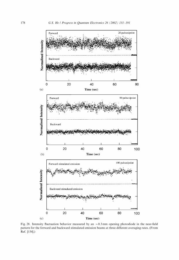
Fig. 28. Intensity fluctuation behavior measured by an B0.3 mm opening photodiode in the near-field
pattern for the forward and backward stimulated emission beams at three different averaging rates. (From
Ref. [154].)
G.S. He / Progress in Quantum Electronics 26 (2002) 131–191178
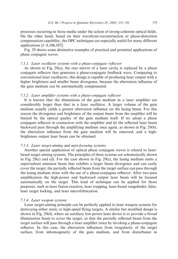
processes occurring in those media under the action of strong coherent optical fields.On the other hand, based on their wavefront-reconstruction or phase-distortioncompensation capability, the OPC techniques are especially useful for many differentapplications [1–8,106,107].
Fig. 29 shows some distinctive examples of practical and potential applications ofphase conjugate waves.
7.1.1. Laser oscillator systems with a phase-conjugate reflector
As shown in Fig. 29(a), the rear mirror of a laser cavity is replaced by a phaseconjugate reflector that generates a phase-conjugate feedback wave. Comparing toconventional laser oscillators, this design is capable of producing laser output with ahigher brightness and smaller beam divergence, because the aberration influence ofthe gain medium can be automatically compensated.
7.1.2. Laser amplifier systems with a phase-conjugate reflector
It is known that the dimensions of the gain medium in a laser amplifier areconsiderably larger than that in a laser oscillator. A larger volume of the gainmedium usually yields a greater aberration influence on the lasing beam. For thisreason the divergence and brightness of the output beam from the amplifier will belimited by the optical quality of the gain medium itself. If we adopt a phaseconjugate reflector in connection with the amplifier and let the reflected laser beambackward pass through the amplifying medium once again, as shown in Fig. 29(b),the aberration influence from the gain medium will be removed, and a high-brightness output laser beam can be obtained.
7.1.3. Laser target-aiming and auto-focusing systems
Another special application of optical phase conjugate waves is related to laser-based target-aiming systems. The principles of these systems are schematically shownin Fig. 29(c) and (d). For the case shown in Fig. 29(c), the lasing medium emits asuperradiant emission beam that exhibits a larger beam divergence and can easilycover the target, the partially reflected beam from the target surface can pass throughthe lasing medium twice with the use of a phase-conjugate reflector. After two-passamplification the high-power and backward output laser beam will be focusedautomatically on the target. This kind of technique can be applied for thosepurposes, such as laser fusion reaction, laser trapping, laser-based rangefinder, lidar,laser target locking, and laser microfabrication.
7.1.4. Laser weapon systems
Laser target-aiming principle can be perfectly applied to laser weapon systems fordestroying either static or high-speed flying targets. A similar but modified design isshown in Fig. 29(d), where an auxiliary low-power laser device is to provide a broadillumination beam to cover the target, so that the partially reflected beam from thetarget surface will pass through a laser amplifier twice by invoking a phase-conjugatereflector. In this case, the aberration influences from irregularity of the targetsurface, from inhomogeneity of the gain medium, and from disturbance in
G.S. He / Progress in Quantum Electronics 26 (2002) 131–191 179

transmission medium can be automatically removed, and the total energy of theamplified laser beam can be efficiently focused on the target to destroy it.
7.1.5. Laser identification and rescue systems
A suggested laser-based friend-or-foe identification system is schematically shownin Fig. 29(e), in which a cooperative lasing material-made target is equipped on anaircraft, a warship, or an armored vehicle. Utilizing a laser aiming system to search
Lasing MediumPhase-Conjugate
ReflectorMirror
Laser AmplifierPhase-Conjugate
ReflectorInput
Output Phase-ConjugateReflector
Lasing MediumTarget
Phase ConjugateReflector
Laser Amplifier
Laser
(a)
(b)
(c)
(d)
Target
Searching Laser
λ
λ'Amplifier and Detector
(Lasing Material)
Target
(e)
Fig. 29. (a) High-brightness laser oscillator with a phase conjugate reflector as the rear cavity-reflector, (b)
high-brightness two-pass laser amplifier with a phase conjugate reflector, (c) laser target-aiming and auto-
focusing system, (d) laser target-aiming and weapon system, (e) laser identification and rescue system.
G.S. He / Progress in Quantum Electronics 26 (2002) 131–191180

this cooperative target and then focusing the pump laser beam on it, the inducedbackward and phase-conjugate stimulated emission beam with special wavelengthwill go back to the laser searching system, to be detected and identified. Obviously,this technique can also be used for rescue of military persons when a radio-silencehas to be kept.
7.2. Some examples of OPC application studies
In this subsection we shall give some specific examples of OPC application studies.
7.2.1. Laser oscillator/amplifier systems using stimulated Brillouin scattering mirror
Stimulated Brillouin scattering (SBS) [155–159] is the most efficient techniqueapplied to laser oscillator/amplifier systems, to provide phase-conjugate feedbackand to compensate the aberration influence of lasing media. As the frequency-shift ofSBS is much less than the gain width of a given lasing medium, the reflected phase-conjugate beam can be effectively amplified. In fact, a Brillouin cell plays the role ofphase-conjugate mirror. The cell may contain a transparent liquid (such as CS2,CCl4, acetone, n-hexane, cyclohexane, Freon) system, or a high-pressure gas (such asSF6, CH4, N2) system. The nonlinear reflectivity can be higher than 70–80%.
7.2.2. OPC-associate nonlinear spectroscopy
Four-wave mixing based OPC [100,160–163] can be employed as a novelspectroscopic method to investigate the energy state structure, spectral width, andpopulation relaxation of a given resonant nonlinear medium.
7.2.3. OPC-associate phase-locking
Photorefractive crystal based OPC elements, such as the so-called doublephase-conjugate mirror, can be utilized to couple two separate laser systems andto keep a synchronized phase relationship between them [164–169]. The laser phase-locking can also be implemented using Brillouin-enhanced FWM method [56]. Inaddition, the OPC technique is also specially useful for two-beam optical trappingpurpose [170].
7.2.4. OPC-associate interferometry
Combining OPC technique with the conventional interferometry [171,172] mayprovide at least two benefits. One is making the rigorous optical alignment mucheasier, the other is reducing the environmental disturbance on the measurements.
7.2.5. OPC-associated optical data processing
OPC technique [173–178] will be more useful for optical data recording/reading[173,174], transmission through disturbing medium [96,175,176], memories [177],and filtering [178].
G.S. He / Progress in Quantum Electronics 26 (2002) 131–191 181

7.3. Midway OPC for fiber communication systems
In regard to recent OPC applications, the most significant breakthrough is theadoption of OPC in upgraded long-distance optical fiber communication systems. Itis well known that to achieve high-bit-rate data transmission through a super-longoptical fiber network, the following two requirements are essentially important.First, suitable optical wavelengths should be chosen at which the transmission loss inthe fiber network is minimized. Second, an appropriate multichannel mechanismshould be employed, either in wavelength-division multiplexing (WDM) or time-division multiplexing (TDM) regime. To meet the first requirement, the wavelengthsof optical carrier wave are usually chosen either in B1.3 or in 1.5 mm region wheretwo windows of transmission loss are located. Concerning the second requirement,however, there are two major limitations imposed on the transmission bit-rate aswell as the transmission distance via an optical fiber network. The first limitationcomes from the so-called chromatic dispersion or group-velocity dispersion (GVD)effect that means the optical pulses having different spectral components exhibitdifferent propagation velocities along a fiber transmission system. Because of thiseffect, an ultra-short optical pulse, which contains multi-spectral-components withina considerable spectral width, will become broader in time-scale during propagationwithin a long fiber system. For this reason, the temporal spacing between twoadjacent optical pulses cannot be less than a certain value for a given fiber length,and the transmission bit-rate is limited. The chromatic dispersion of an optical fibersystem is defined as [179]
DðlÞ ¼1
L
dtdl
¼1
L
d
dl
Ll2s
2pc
dbdl
ls
" #¼
l2s
2pc
d2b
dl2
ls
; ð49Þ
where t is the time delay for an optical pulse propagating in a single-mode fiber oflength L; b is the propagation constant of the fiber, ls is the central wavelength of theoptical signal, and c is the speed of light. For most standard single-mode fibers thezero-dispersion wavelength is l0E1:3 mm at which Dðl0ÞE0; in a signal wavelengthregion of lsE1:5 mm the chromatic dispersion DðlsÞEð15218Þ ps/km/nm. Thechromatic-dispersion-limited transmission distance over this type of fiber (for a 1-dBpenalty) is given by [180]
B2LD6500 ðGbit=sÞ2km: ð50Þ
Here B is the bit-rate and L is the fiber length. The limit, for example, is B65 km at abit-rate of 10 Gbit/s.
In addition to the limitation from chromatic dispersion, there is another limitationthat is related to the spectral broadening of optical pulses propagating in a fibersystem. It is known that an optical fiber is a good third-order nonlinear medium, inwhich many nonlinear optical effects can easily take place. Among these effects, thelight-intensity dependent refractive-index change may produce self-modulation of anintense short light pulse during its propagation in the fiber system. Sequentially, thisself-modulation effect leads to a spectral self-broadening of the given light pulse.
G.S. He / Progress in Quantum Electronics 26 (2002) 131–191182

Some other nonlinear processes, such as four-wave mixing or stimulated scatteringmay also produce new spectral components or cause further spectral broadening.This kind of spectral broadening may degrade the quality of signal transmission andparticularly impose a limitation on the minimum spectral spacing between twoadjacent channels in a fiber communication system adopting WDM regime.
The latest development of optical fiber communication technology in the recent 10years has shown that the optical phase conjugation (OPC) technique can besuccessfully employed to overcome the limitations from chromatic dispersion and self-modulation (spectral self-broadening) respectively. In this case a special optical phase-conjugator is placed in the middle of two identical single-mode fiber transmissionsystems, which generates phase-conjugate waves of the input signal waves with aninverse spectral structure. This special technique adopted for fiber communications iscalled ‘‘midway optical phase conjugation (MOPC)’’ or ‘‘mid-span spectral inversion(MSSI). The principle of this technique is based on the theoretical proposal reportedby Yariv et al. in 1979 [181]. In this proposal a midway phase-conjugator is placedbetween two identical fiber systems and to generate a phase conjugate wave atfrequency opc ¼ ðo0 OÞ with respect to the input signal wave of frequency os ¼ðo0 þ OÞ: It was theoretically proven that in this specific case, the chromaticdispersion and self-modulation influence from the first fiber system on the opticalsignal could be compensated by that from the second fiber system. In that originalpaper the midway phase-conjugator was suggested to be working with the method ofbackward nondegenerate FWM under the following condition: 2o0 ¼ os þ opc ¼ðo0 þ OÞ þ ðo0 OÞ; where o0 was the frequency of two counter-propagating pumpbeams. In 1992, Inoue reinvestigated this issue theoretically and suggested the use offorward nondegenerate FWM in an optical fiber as a new approach of midway phase-conjugation [182]. To fulfill the phase-matching requirement of FWM, it was alsosuggested that o0; os and opc should be chosen working in the spectral region near tozero-dispersion wavelength. The first experimental demonstration of MSSI in adispersion-shifted fiber section using forward FWM was reported in 1993 byWatanabe et al. [183] and subsequently by Jopson et al. [184].
Fig. 30 shows a schematic of an optical fiber communication system containingtwo identical signal-mode fiber spans with a midway optical phase-conjugator,as well as the compensation of chromatic dispersion and spectral broadening byMSSI technique. For simplicity, the assumed input light pulse has an originalFourier-transform limited spectrum distribution with the central frequency locatedat ðo0 OÞ: During its propagation over the first fiber span, the pulse envelopegradually broadens due to GVD dispersion, as shown in Fig. 30(b), while itsspectrum becomes distorted and broadened owing to self-modulation, as shownin Fig. 30(c). After a midway phase-conjugator, the phase-conjugate pulse isgenerated at a new central frequency ðo0 þ OÞ with an inverse spectrum distributionrelated to that of the signal pulse. Assuming the red-end spectral-components of thesignal pulse propagate faster in the first fiber span than the blue-end, then afterpassing through a midway phase-conjugator, the red-end components of the signalpulse are converted into the blue-end components of the phase-conjugated pulse and,therefore, will propagate slower in the second fiber span. For that reason, the
G.S. He / Progress in Quantum Electronics 26 (2002) 131–191 183

chromatic dispersion influences from two fiber spans can be cancelled from eachother. One may readily realize that the nonlinear self-modulation related spectralbroadening influence can also be compensated because of the forward phase-conjugation nature. As we mentioned in Section 3.4, two technical approaches canbe used to generate forward PCW with spectral inversion: one is FWM in a third-order ðwð3ÞÞ nonlinear medium, and the other is three-wave mixing in a second-orderðwð2ÞÞ nonlinear medium. As indicated in Fig. 30(a), the pump frequency should beop ¼ o0 in the former case, whereas op ¼ 2o0 in the latter case. In both cases, thefrequency detuning O from o0 value should be small.
In practice three types of nonlinear media have been employed for MSSIpurpose.
7.3.1. Dispersion-shifted fiber (DSF) systems
The most adopted optical fibers for long-distance transmission purpose areconventional single-mode standard fibers with their zero-dispersion wavelengthlocated in B1.3 mm region. However, the most commonly adopted opticalwavelengths are chosen in B1.5 mm region because of the low propagation lossesand the capability of using erbium-doped fiber amplifier in this spectral region. Inorder to achieve efficient nondegenerate FWM for MSSI purpose, the so-calleddispersion-shifted fiber (DSF) [185–192] can be employed as the nonlinear medium,in which the zero-dispersion wavelength is shifted to the B1.5 mm region. In practicethe fiber length used for optical phase-conjugator usually ranges from several km toseveral tens of km.
Fig. 30. (a) Schematic diagram showing midway optical phase conjugation (mid-span spectral inversion)
between two long spans of single-mode fibers, (b) waveform changes of the input signal pulse and output
phase-conjugate pulse, (c) spectrum changes of the input signal pulses and output phase-conjugate
pulse.
G.S. He / Progress in Quantum Electronics 26 (2002) 131–191184

7.3.2. Semiconductor optical amplifier (SOA) systems
As mentioned in Section 4.3, FWM may efficiently take place in optically pumpedlasing media because of their higher effective wð3Þ values. Under those circumstancesa higher phase-conjugate output power could be obtained due to the additionalsimulated amplifying effect. In practice, both the semiconductor optical amplifiers(SOA) [193–198] and semiconductor lasers [199,200] could be employed as midwayphase-conjugators for MSSI purpose.
7.3.3. Second-order nonlinear waveguide systems
The advantages of using three-wave mixing in a second-order nonlinear mediumto generate forward PCW with spectral inversion are the high efficiency and the
Single modefiber span 1
Midway optical phase-conjugator
Transmitter R
Single modefiber span 2
EDFA EDFABPF BPF
Signal input
PCW output
Pump source
λs
λp
λpc
Fiber coupler
Dispersion shifted fiber (DSF)
Nonlinear medium
(for FWM)
Semiconductoroptical amplifier (SOA)
(for FWM)
Periodically poledLiNbO3 waveguide
(for three-wave mixing)
(a)
(b)
(c)
Receiver
Fig. 31. (a) Midway optical phase conjugation (MOPC) employed in long transmission distance and high
bit-rate optical fiber communication systems, (b) basic components of a midway optical phase-conjugator,
(c) three types of nonlinear media for MOPC purposes. BPF: band-pass filter; EDFA: erbium-doped fiber
amplifier; FWM: four-wave mixing; PCW: phase-conjugate wave.
G.S. He / Progress in Quantum Electronics 26 (2002) 131–191 185

compactness of devices. In practice, a periodically poled LiNbO3 waveguide has beenadopted as a midway phase-conjugator for MSSI performance [201,202]. Theemployed mechanism is the cascaded wð2Þ processes.
Fig. 31 shows schematically the basic components of a generalized midway opticalphase-conjugator in a complete modern optical fiber communication system. Asshown in Fig. 31(b), after propagating over the first transmission fiber span, thedistorted signal pulses pass through an erbium-doped fiber amplifier (EDFA) and aband-pass filter (BPF) then enter the nonlinear medium for wave-mixing. In themean time, the pump light usually from a semiconductor laser or fiber distributedfeedback laser is launched into the same nonlinear medium through a fiber coupler.After completion of four-wave or three-wave mixing, the newly generated phase-conjugate output passes through another BPF and EDFA then enters the secondtransmission fiber span.
Based on MOPC or MSSI technique, the data-transmission rate and distancethrough optical fiber links can be significantly increase. For example, at 10 Gbit/sbit-rate the transmission distance through two standard single-mode fiber spans hasbeen increased to 200 km using FWM in a semiconductor optical amplifier (SOA)[203] or 560 km using FWM in a 7.8 km dispersion-shifted fiber (DSF) [204]. At40 Gbit/s and with a SOA-based phase-conjugator, the fiber transmission distancecould be up to 204 km [205]. Furthermore, at an ultra-high bit-rate for 80 Gbit/s, thedistance could be up to 106 km using a SOA-based phase-conjugator [206,207].
Finally, it should be noted that the same MOPC principle can also be employed inthe future fiber soliton communication systems to improve the optical datatransmission rate and quality [208–211].
Acknowledgements
The author wishes to thank Dr. P. N. Prasad, Distinguished Professor andExecutive Director of Institute for Lasers, Photonics and Biophonics, StateUniversity of New York at Buffalo, for his valuable support in conducting researchactivity. The author is also indebted to those authors whose works have been quotedin this review article. Finally, T.-C. Lin’s assistance is particularly appreciated.
References
[1] A. Yariv, IEEE Journal of Quantum Electronics QE-14 (1978) 650–660.
[2] R.W. Hellwarth, Optical Engineering 21 (1982) 257–262.
[3] R.A. Fisher, (ed.), Optical Phase Conjugation, Academic, New York, 1983.
[4] B.Ya. Zel’dovich, N.F. Pilipetsky, V.V. Shkunov, Principles of Phase Conjugation, Springer-Verlag,
Berlin, 1985.
[5] G.S. He, S.H. Liu, Physics of Nonlinear Optics, World Scientific, New Jersey, 2000.
[6] H.J. Eichler, P. Gunter, D.W. Pohl, (ed.), Laser Induced Dynamic Gratings, Springer-Verlag,
Berlin, 1986.
[7] M.C. Gower, Progress in Quantum Electronics 9 (1984) 101–147.
[8] V.T. Tikhonchuk, A.A. Zozulya, Progress in Quantum Electronics 15 (1991) 231–293.
G.S. He / Progress in Quantum Electronics 26 (2002) 131–191186

[9] R.W. Hellwarth, Journal of the Optical Society of America A67 (1977) 1–3.
[10] D.M. Bloom, G.C. Bjorklund, Applied Physics Letters 31 (1977) 592–594.
[11] B.Ya. Zel’dovich, V.I. Popovichev, V.V. Ragul’skii, F.S. Faizullov, JETP Letters 15 (1972)
109–113.
[12] O.Yu. Nosach, V.I. Popovichev, V.V. Ragul’skii, F.S. Faizullov, JETP Letters 16 (1972) 435–438.
[13] V.G. Koptev, A.M. Lazaruk, I.P. Petrovich, A.S. Rubanov, JETP Letters 28 (1978) 434–436.
[14] G.S. He, Y. Cui, M. Yoshida, P.N. Prasad, Optics Letters 22 (1997) 10–12.
[15] C.V. Heer, N.C. Griffen, Optics Letters 4 (1979) 239–241.
[16] A. Khyzniak, V. Kondilenko, Yu. Kucherov, S. Lesnik, S. Odoulov, M. Soskin, Journal of the
Optical Society of America A1 (1984) 169–179.
[17] A. Yariv, Applied Physics Letters 28 (1976) 88–89;
A. Yariv, Journal of the Optical Society of America 66 (1976) 301–306;
A. Yariv, Optics Communications 21 (1977) 49–50.
[18] P.V. Arizonis, F.A. Hopf, W.D. Bamberger, S.F. Jacobs, A. Tomita, K.H. Womack, Applied
Physics Letters 31 (1977) 435–437.
[19] N.C. Griffin, C.V. Heer, Applied Physics Letters 33 (1978) 865–866.
[20] N.S. Shiren, Applied Physics Letters 33 (1978) 299–300.
[21] A. Yariv, D.M. Pepper, Optics Letters 1 (1977) 16–18.
[22] R.L. Abrams, R.C. Lind, Optics Letters 2 (1978) 94–96;
R.L. Abrams, R.C. Lind, Erratum 3 (1978) 205.
[23] D.G. Steel, R.C. Lind, J.F. Lam, C.R. Giuliano, Applied Physics Letters 35 (1979) 376–379.
[24] G. Martin, R.W. Hellwarth, Applied Physics Letters 34 (1979) 371–373.
[25] J. Takacs, H.C. Ellin, L. Solymar, Optics Communications 93 (1992) 223–226.
[26] L. Lefort, A. Barthelemy, Optics Letters 21 (1996) 848–850.
[27] F. Devaux, E. Guiot, E. Lantz, Optics Letters 23 (1998) 1597–1599.
[28] G. Eckhardt, R.W. Hellwarth, F.J. McClung, S.E. Schwarz, D. Weiner, E.J. Woodbury, Physical
Review Letters 9 (1962) 455–457.
[29] R.Y. Chiao, C.H. Townes, B.P. Stoicheft, Physical Review Letters 12 (1964) 592–595.
[30] D.I. Mash, V.V. Morozov, V.S. Starunov, I.L. Fabelinskii, JETP Letters 2 (1965) 25–27.
[31] G.S. He, P.N. Prasad, Physical Review A 41 (1990) 2687–2697.
[32] D. Liu, G.S. He, Soviet Physics, JETP 88 (1999) 235–245.
[33] G.S. He, P.N. Prasad, Journal of the Optical Society of America B15 (1998) 1078–1085.
[34] G.S. He, N. Cheng, P.N. Prasad, D. Liu, S.H. Liu, Journal of the Optical Society of America B15
(1998) 1086–1095.
[35] S.M. Jensen, R.W. Hellwarth, Applied Physics Letters 32 (1978) 166.
[36] E.E. Bergmann, I.J. Bigio, B.J. Feldman, R.A. Fisher, Optics Letters 3 (1978) 82–84.
[37] M.A. Khan, P.W. Kruse, J.F. Ready, Optics Letters 5 (1980) 261–263.
[38] D. Fekete, J. AuYeung, A. Yariv, Optics Letters 5 (1980) 51–53.
[39] D. Grischkowsky, N.S. Shiren, R.J. Bennett, Applied Physics Letters 33 (1978) 805–807.
[40] D.M. Bloom, P.F. Liao, N.P. Ecnomou, Optics Letters 2 (1978) 58–60.
[41] P.F. Liao, D.M. Bloom, Optics Letters 3 (1978) 4–6.
[42] R.C. Lind, D.G. Steel, M.B. Klein, R.L. Abrams, C.R. Giuliano, R.K. Jain, Applied Physics Letters
34 (1979) 457–459.
[43] A. Tomita, Applied Physics Letters 34 (1979) 463–464.
[44] D. Depatie, D. Haueisen, Optics Letters 5 (1980) 252–254.
[45] R.K. Jain, M.B. Klein, Applied Physics Letters 35 (1979) 454–456.
[46] E.I. Moses, F.Y. Wu, Optics Letters 5 (1980) 64–66.
[47] J. Nilsen, A. Yariv, Optics Communications 39 (1981) 199–204.
[48] Y.L. Guo, M.-Y. Yao, S.-M. Pang, IEEE Journal of Quantum Electronics 20 (1984) 328–331.
[49] H.A. Mac Kenzie, D.J. Hagan, H.A. Al-Attar, IEEE Journal of Quantum Electronics QE-22 (1986)
1328–1340.
[50] M. Ducloy, Applied Physics Letters 46 (1985) 1020–1022.
[51] M.T. De Araujo, S.S. Vianna, G. Grynberg, Optics Communications 80 (1990) 79–83.
G.S. He / Progress in Quantum Electronics 26 (2002) 131–191 187

[52] N.A. Andreev, V.-I. Bespalov, A.M. Kiselev, A.Z. Matveev, G.A. Pasmanik, A.A. Shilov, JETP
Letters 32 (1980) 625–629.
[53] M.D. Skeldon, P. Narum, R.W. Boyd, Optics Letters 12 (1987) 343–345.
[54] A.M. Scott, K.D. Ridlex, IEEE Journal of Quantum Electronics 25 (1989) 438–459.
[55] Y.-S. Kuo, Y.-C. Fong, C. Wu, J.G. McInerney, K. McIver, Optics Communications 97 (1993) 228–
232.
[56] M.W. Bowers, R.W. Boyd, IEEE Journal of Quantum Electronics 34 (1998) 634–644.
[57] W.M. Dennis, W. Blau, Optics Communications 57 (1986) 371–375.
[58] A. Costela, J.M. Figuera, F. Florido, Optics Communications 100 (1993) 536–544.
[59] B.R. Reddy, P. Venkateswarlu, Journal of the Optical Society of America B10 (1993) 438–445.
[60] A. Costela, I. Garcia-Moreno, Chemical Physics Letters 249 (1996) 373–380.
[61] S.M. Kuebler, R.G. Denning, Chemical Physics Letters 250 (1996) 120–127.
[62] G.R. Kumar, B.P. Singh, K.K. Sharma, Optics Communications 73 (1989) 81–84.
[63] H. Nakatsuka, D. Masuoka, T. Yamamoto, Optics Communications 80 (1991) 215–218.
[64] E. Mohajerani, E. Whale, G.R. Mitchell, Optics Communications 92 (1992) 403–410.
[65] S. Miyanaga, H. Ohtateme, K. Kawano, H. Fujiwara, Journal of the Optical Society of America B10
(1993) 403–410.
[66] C. O’Neill, V. Blanchet, M.-M.D. Roberge, P. Galarenau, Canadian Journal of Physics 71 (1993)
442–447.
[67] A. Costela, J.M. Figuera, F. Florido, I. Garcia-Moreno, R. Sastre, Optics Communications 119
(1995) 265–274.
[68] R.K. Mohan, C.K. Subramanjan, Optics Communications 144 (1997) 322–330.
[69] R.K. Jain, R.C. Lind, Journal of the Optical Society of America 73 (1983) 647–653.
[70] P. Roussignol, D. Ricard, K.C. Rustagi, C. Flytzanis, Optics Communications 55 (1985) 143–148.
[71] F. Hache, D. Richard, C. Flyzanis, U. Kreibig, Applied Physics A 47 (1988) 347–357.
[72] J.T. Remillard, H. Wang, M.D. Webb, D.G. Steel, IEEE Journal of Quantum Electronics 25 (1989)
408–413.
[73] P. Roussignal, D. Ricard, J. Lukasik, G. Flytzanis, Journal of the Optical Society of America B4
(1987) 5–13.
[74] S.M. Saltiel, B.V. Wonterghem, T.E. Dutton, J.A. Hutchinson, P.M. Rentzepis, IEEE Journal of
Quantum Electronics 24 (1988) 2302–2307.
[75] P. Nandakumar, C. Vijavan, Y.V.G.S. Murti, Optics Communications 185 (2000) 457–465.
[76] S.Y. Yuen, P. Becla, Optics Letters 8 (1983) 356–358.
[77] D.G. Steel, S.C. Rand, J. Liu, Journal of the Optical Society of America B4 (1987) 1794–1800.
[78] T. Shimura, S.A. Boothroyd, J. Chrostowski, P. Myslinski, Optics Communications 101 (1993)
124–132.
[79] Y. Zhao, C. Wu, P. Shah, M.K. Kim, L.R. Dawson, Applied Physics Letters 63 (1993) 281–283.
[80] R. Vijava, Y.V.G.S. Murti, G. Sundararajan, C.K. Mathews, P.R. Vasudeva Rao, Optics
Communications 94 (1992) 353–356.
[81] A. Costela, I. Carcia-Mareno, J.L. Saiz, Journal of the Optical Society of America B 14 (1997) 615–619k.
[82] A. Costela, I. Garcia-Mareno, J.L. Saiz, Journal of Physical Chemistry B 101 (1997) 4897–4903.
[83] I.C. Khoo, H. Li, Y. Liang, Optics Letters 18 (1993) 1490–1492.
[84] S.-H. Chen, Y. Shen, Journal of the Optical Society of America B 14 (1997) 1750–1753.
[85] A. Miniewicz, S. Bartkiewicz, J. Parka, Optics Communications 149 (1998) 89–95.
[86] I.C. Khoo, Y. Liang, Physical Review E 62 (2000) 6722–6733.
[87] R.A. Fisher, B.J. Feldman, Optics Letters 4 (1979) 140–142.
[88] G.J. Groft, R.P.M. Green, M.J. Damzen, Optics Letters 17 (1992) 920–922.
[89] R.P.M. Green, G.J. Grofts, M.J. Damzen, Optics Communications 102 (1993) 288–292.
[90] A. Brignon, J.-P. Huignard, IEEE Journal of Quantum Electronics 30 (1994) 2203–2210.
[91] R.P.M. Green, G.J. Groft, M.J. Damzen, Optics Letters 19 (1994) 393–395.
[92] A. Brignon, G. Feugnet, J.-P. Huignard, J.-P. Pocholle, Optics Letters 20 (1995) 548–550.
[93] V.V. Krasnikov, V.M. Petnikova, M.S. Pshenishinikov, V.S. Sholomatin, V.V. Shuvalov, Soviet
Journal of Quantum Electronics 13 (1983) 983–984.
G.S. He / Progress in Quantum Electronics 26 (2002) 131–191188

[94] P.R. Hemmer, D.P. Katz, J. Donoghue, M. Gronin-Golomb, M.S. Shahriar, P. Kumar, Optics
Letters 20 (1995) 982–984.
[95] M.Y. Lanzerotti, R.W. Schirmer, A.L. Gaeta, Applied Physics Letters 69 (1996) 1199–1201.
[96] V.S. Sudarshanam, M. Gronin-Golomb, P.R. Hemmer, M.S. Shahriar, Optics Letters 22 (1997)
1141–1143.
[97] D.S. Hsiung, X.-W. Xia, T.T. Grove, M.S. Shahriar, P.P. Hemmer, Optics Communications 154
(1998) 79–82.
[98] M.Y. Lanzerotti, R.W. Schirmer, A.L. Gaeta, G.S. Agarwal, Physical Review A 60 (1999)
4980–4985.
[99] G.C. Cardoso, J.W.R. Tabosa, Optics Communications 185 (2000) 353–358.
[100] T.T. Grove, E. Rousseau, X.-W. Xia, D.S. Hsiung, M.S. Shahriar, P.R. Hemmer, Optics Letters 22
(1997) 1677–1679.
[101] A. Ashkin, G.D. Boyd, J.M. Dziedzic, R.G. Smith, A.A. Ballman, J.J. Levinstein, K. Nassau,
Applied Physics Letters 9 (1966) 72–74.
[102] F.S. Chen, J.T. LaMacchia, D.B. Frazer, Applied Physics Letters 13 (1968) 223–225.
[103] P. Yeh, Introduction to Photorefractive Nonlinear Optics, Wiley, New York, 1993.
[104] P. G .unter, J.P. Huignard, Photorefractive Materials and Their Applications I &II, Topic in Applied
Physics, Vol. 61, Springer-Verlag, Berlin, 1988, 1989.
[105] W.E. Moerner, Scott M. Silence, Chemical Reviews 94 (1994) 127–155.
[106] B. Fischer, S. Sternklar, S. Weiss, IEEE Journal of Quantum Electronics 25 (1989) 550–569.
[107] P. Yeh, IEEE Journal of Quantum Electronics 25 (1989) 484–519.
[108] V. Wang, C.R. Giuliano, Optics Letters 2 (1978) 4–6.
[109] M. Slatkine, I.J. Bigio, B.J. Feldman, R.A. Fisher, Optics Letters 7 (1982) 108–110.
[110] E. Armandilo, D. Proch, Optics Letters 8 (1983) 523–525.
[111] I.V. Tomov, R. Fedosejevs, D.C.D. McKen, Optics Letters 9 (1984) 405–407.
[112] M.T. Duignan, B.J. Feldman, W.T. Whitney, Optics Letters 12 (1987) 111–113.
[113] D.R. Hull, R.A. Lamb, J.R. Digman, Optics Communications 72 (1989) 104–108.
[114] R.P. Johnson, Optics Communications 77 (1990) 231–234.
[115] J.J. Ottusch, D.A. Rockwell, Optics Letters 16 (1991) 369–371.
[116] M.R. Osborne, M.A. O’key, Optics Communications 94 (1992) 346–352.
[117] C.B. Dane, W.A. Neuman, L.A. Hackel, Optics Letters 18 (1992) 1271–1273.
[118] S. Jackel, P. Shalev, R. Lallouz, Optics Communications 101 (1993) 411–415.
[119] R.G. Harrison, V.I. Kovalev, W. Lu, D. Yu, Optics Communications 163 (1999) 208–211.
[120] B.Ya. Zel’dovich, N.A. Mel’nikov, N.F. Pilipetskii, V.V. Ragul’skii, JETP Letters 25 (1977) 36–39.
[121] A.I. Sokolovskaya, G.L. Brekhovskikh, A.D. Kudryavtseva, Soviet Physics, Doklady 22 (1977)
156–158.
[122] A.I. Sokolovskaya, G.L. Brekhovskikh, A.D. Kudryavtseva, Optics Communications 24 (1978)
74–76.
[123] R. Mays, R.J. Lysiak, Optics Communications 31 (1979) 89–92.
[124] I.V. Tomov, R. Fedosejevs, D.C.D. McKen, C. Domier, A.A. Offenberger, Optics Letters 8 (1983)
9–11.
[125] A.I. Sokolovskaya, G.L. Brekhovskikh, A.D. Kudryavtseva, IEEE Journal of Quantum Electronics
QE-23 (1987) 1332–1343.
[126] A.D. Kudryavtseva, A.I. Sokolovskaya, J. Gazengel, N. Phu Xuan, G. Rivoire, Optics
Communications 26 (1978) 446–448.
[127] J.L. Ferrier, Z. Wu, J. Gazengel, N. Phu Xuan, G. Rivoire, Optics Communications 41 (1982) 135–
139.
[128] E.J. Miller, M.S. Malcuit, R.W. Boyd, Optics Letters 15 (1990) 1188–1190.
[129] J. Feinberg, Optics Letters 7 (1982) 486–487.
[130] J.O. White, M. Cronin-Golomb, B. Fischer, A. Yariv, Applied Physics Letters 40 (1982) 450–452.
[131] T.Y. Chang, R.W. Hellwarth, Optics Letters 10 (1985) 408–410.
[132] R.A. Mullen, D.J. Vickers, L. West, D.M. Pepper, Journal of the Optical Society of America B9
(1992) 1726–1734.
G.S. He / Progress in Quantum Electronics 26 (2002) 131–191 189

[133] Y. Lian, H. Gao, P. Ye, Q. Guan, J. Wang, Applied Physics Letters 63 (1993) 1745–1747.
[134] L. Zhang, Z. Shao, X. Mu, H. Chen, M. Jiang, Optics Communications 123 (1996) 587–591.
[135] R.W. Hellwarth, Journal of the Optical Society of America 68 (1978) 1050–1056.
[136] H. Hsu, S.S. Bor, IEEE Journal of Quantum Electronics 25 (1989) 430–437.
[137] G.G. Kochemasov, V.D. Nikolaev, Soviet Journal of Quantum Electronics 7 (1977) 60–62.
[138] I.M. Bel’dyugin, M.G. Galushkin, E.M. Zemskov, V.I. Mandrosov, Soviet Journal of Quantum
Electronics 6 (1976) 1349–1351.
[139] B.Ya. Zel’dovich, V.V. Shkunov, Soviet Journal of Quantum Electronics 7 (1977) 610–615.
[140] N.B. Baranova, B.Ya. Zel’dovich, V.V. Shkunov, Soviet Journal Quantum Electronics 8 (1978)
559–566.
[141] N.B. Baranova, B.Ya. Zel’dovich, Soviet Journal Quantum Electronics 10 (1980) 555–560.
[142] V.I. Bespalov, V.G. Manishin, G.A. Pasmanik, Soviet Physics, JETP 50 (1979) 879–886.
[143] V.G. Sidorovich, V.V. Shkunov, Soviet Physics, Technical Physics 24 (1979) 472–476.
[144] G.S. He, D. Liu, S.H. Liu, Bulletin of the American Physical Society 30 (1985) 1800.
[145] G.S. He, D. Liu, S.H. Liu, Chinese Physics, Lasers 13 (1986) 713–717.
[146] M. Born, E. Wolf, Principles of Optics, 6th Edition, Pergamon, London, 1983, p. 453.
[147] G.S. He, J.D. Bhawalkar, C.F. Zhao, C.K. Park, P.N. Prasad, Optics Letters 20 (1995) 2393–2395.
[148] G.S. He, J.D. Bhawalkar, C.F. Zhao, P.N. Prasad, IEEE Journal of Quantum Electronics 32 (1996)
749–755.
[149] G.S. He, J.D. Bhawalkar, C.F. Zhao, C.K. Park, P.N. Prasad, Applied Physics Letters 68 (1996)
3549–3551.
[150] G.S. He, L. Yuan, Y. Cui, M. Li, P.N. Prasad, Journal of Applied Physics 81 (1997) 2529–2537.
[151] G.S. He, K.S. Kim, L. Yuan, N. Cheng, P.N. Prasad, Applied Physics Letters 71 (1997) 1619–1621.
[152] G.S. He, P.N. Prasad, IEEE Journal of Quantum Electronics 34 (1998) 473–481.
[153] G.S. He, P.P. Markowicz, T.-C. Lin, P.P. Prasad, Nature 415 (2002) 767–770.
[154] G.S. He, J. Dai, T.-C. Lin, N. Cheng, P.P. Markowicz, P.P. Prasad, to be submitted.
[155] M. Sugii, M. Okabe, A. Watanabe, K. Sasaki, IEEE Journal of Quantum Electronics 24 (1988)
2264–2269.
[156] N.A. Kurnit, S.J. Thamas, IEEE Journal of Quantum Electronics 25 (1989) 421–429.
[157] R.J.St. Pierre, D.W. Mordaunt, H. Injeyan, J.G. Berg, R.C. Hillard, M.E. Weber, M.G. Wickham,
G.M. Harpole, R. Senn, IEEE Journal of Selected Topics in Quantum Electronics 3 (1997) 53–58.
[158] B. Kralikova, J. Skala, P. Straka, H. Turcicova, Optics Letters 11 (1997) 766–768.
[159] E.J. Friebele, M. Baskansky, J. Reintjes, Electronics Letters 31 (1995) 885–886.
[160] W.H. Richardson, L. Maleki, E. Garmire, IEEE Journal of Quantum Electronics 25 (1989) 382–394.
[161] J.W.R. Tabosa, S.S. Vianna, F.A.M. de Oliveira, Physical Review A 55 (1997) 2968–2972.
[162] L. Lehr, P. Hering, IEEE Journal of Quantum Electronics 33 (1997) 1465–1473.
[163] X.-W. Xia, D. Hsiung, P.S. Bhatia, M.S. Shahriar, T.T. Grove, P.R. Hemmer, Optics
Communications 191 (2001) 347–351.
[164] C. Medrano, M. Ingold, P. G .unter, Optics Communications 77 (1990) 411–414.
[165] G.W. Ross, R.W. Eason, Optics Letters 18 (1993) 571–573.
[166] M.T. Gruneisen, S.H. Chakmakjian, E.D. Seeberger, D.D. Lockett, C.M. Clayton, Optics
Communications 100 (1993) 173–180.
[167] M.W. Wright, J.G. McInerney, C. Wu, Electronics Letters 29 (1993) 1183–1185.
[168] J. Zhang, S.X. Dou, H. Gao, Y. Zhu, P. Ye, Optics Letters 20 (1995) 985–987.
[169] X. Yi, P. Yeh, Optics Communications 107 (1998) 126–130.
[170] W. Wang, A.E. Chiou, G.J. Sonek, M.W. Berns, Journal of the Optical Society of America B14
(1997) 697–707.
[171] G. Yang, A. Siahmakoun, Applied Optics 32 (1993) 1578–1582.
[172] A.-P. Tzannis, P. Beaud, H.-M. Frey, T. Gerber, B. Mischler, P.P. Radi, Applied Optics 36 (1997)
7978–7983.
[173] P.M. Saari, R.K. Kaarli, R.V. Sarapuu, H.R. Sonajalg, IEEE Journal of Quantum Electronics 25
(1989) 339–350.
[174] F. Devaux, G. le Tolguenec, E. Lantz, Optics Communications 147 (1998) 309–312.
G.S. He / Progress in Quantum Electronics 26 (2002) 131–191190

[175] Y. Tomita, R. Yahalom, K. Kyuma, A. Yariv, N.S.-K. Kwong, IEEE Journal of Quantum
Electronics 25 (1989) 315–338.
[176] S. Tukushima, T. Kurokawa, IEEE Journal of Quantum Electronics 29 (1993) 613–618.
[177] Y. Owechko, IEEE Journal of Quantum Electronics 25 (1989) 619–634.
[178] D.Z. Anderson, J. Feinberg, IEEE Journal of Quantum Electronics 25 (1989) 635–647.
[179] C. Lin, H. Kogelnik, L.G. Cohen, Optics Letters 5 (1980) 476–478.
[180] A.H. Gnauck, R.M. Jopson, R.M. Derosier, IEEE Photonics Technology Letters 5 (1993)
663–666.
[181] A. Yariv, D. Fekete, D.M. Pepper, Optics Letters 4 (1979) 52–54.
[182] K. Inoue, Journal of Lightwave Technology 10 (1992) 1553–1562.
[183] S.S. Watanabe, T. Naito, T. Chikama, IEEE Photonics Technology Letters 5 (1993) 92–95.
[184] R.M. Jopson, A.H. Gnauck, Derosier, Electronics Letters 29 (1993) 576–578.
[185] S. Watanabe, T. Chikama, G. Ishikaula, T. Terahara, H. Kuwahara, IEEE Photonics Technology
Letters 5 (1993) 1241–1243.
[186] K. Inoue, T. Hasegawa, K. Oda, H. Toba, Electronics Letters 29 (1993) 1708–1709.
[187] S. Watanabe, T. Chikama, Electronics Letters 30 (1994) 1156–1157.
[188] S. Watanabe, Optics Letters 19 (1994) 1308–1310.
[189] W. Pieper, C. Kurtzke, R. Schnabel, D. Breuer, R. Lundwig, K. Petermann, H.G. Weber,
Electronics Letters 30 (1994) 724–725.
[190] A.H. Gnauck, R.M. Jopson, R.M. Derosier, IEEE Photonics Technology Letters 7 (1995)
582–584.
[191] A. Royset, S.Y. Set, I.A. Goncharenko, R.I. Laming, IEEE Photonics Technology Letters 8 (1996)
449–451.
[192] K. Inoue, Optics Letters 22 (1997) 1772–1774.
[193] M.C. Tatham, G. Sherlock, L.D. Westbrook, Electronics Letters 29 (1993) 1851–1852.
[194] R.M. Jopson, R.E. Tench, Electronics Letters 29 (1993) 2216–2217.
[195] S.Y. Set, H. Geiger, R.I. Laming, M.J. Cole, L. Reekie, IEEE Journal of Quantum Electronics 33
(1997) 1694–1698.
[196] J. Inoue, H. Kawaguchi, IEEE Photonics Technology Letters 10 (1998) 349–351.
[197] H.C. Lim, F. Futami, K. Kikuchi, IEEE Photonics Technology Letters 11 (1999) 578–580.
[198] H. Sotobayashi, K. Kitayama, Journal of Lightwave Technology 17 (1999) 2488–2497.
[199] P.P. Iannone, A.H. Gnauck, P.R. Prucnal, IEEE Photonics Technology Letters 6 (1994)
1046–1049.
[200] S. Watanabe, H. Kuwatsuka, S. Takeda, H. Isshikawa, Electronics Letters 33 (1997) 316–317.
[201] I. Brener, B. Mikkelsen, G. Raybon, R. Harel, K. Parameswaran, J.R. Kurz, M.M. Fejer,
Electronics Letters 36 (2000) 1788–1790.
[202] D. Kunimatsu, C.Q. Xu, M.D. Pelusi, X. Wang, K. Kikuchi, H. Ito, A. Suzuki, IEEE Photonics
Technology Letters 12 (2000) 1621–1623.
[203] M.C. Tatham, X. Gu, L.D. Westbrook, G. Sherlock, D.M. Spirit, Electronics Letters 30 (1994)
1335–1336.
[204] A.H. Gnauck, R.M. Jopson, P.P. Iannone, R.M. Derosier, Electronics Letters 30 (1994) 727–728.
[205] S.Y. Set, S. Yamashita, M. Ibsen, R.I. Laming, D. Nesset, A.E. Kelly, C. Gilbertas, Electronics
Letters 34 (1998) 1681–1683.
[206] H.J. Ehrke, E. Patzak, H.G. Weber, T. Merker, IEEE Photonics Technology Letters 11 (1999)
1063–1065.
[207] T. Merker, P. Meissner, U. Feiste, IEEE Journal of Selected Topics in Quantum Electronics 6 (2000)
258–262.
[208] W. Forysiak, N.J. Doran, Electronics Letters 30 (1994) 154–155.
[209] S. Chi, S. Wen, Optics Letters 19 (1994) 1705–1707.
[210] S. Wen, S. Chi, Electronics Letters 30 (1994) 663–664.
[211] T. Hirooka, A. Hasegawa, Electronics Letters 34 (1998) 2056–2057.
G.S. He / Progress in Quantum Electronics 26 (2002) 131–191 191