review of dimensioning and tolerancing : representation ... · pdf filereview of dimensioning...
TRANSCRIPT

Review of dimensioning and tolerancing : representation and processi ng U Roy, C R Liu* and T C Woo ¢
The paper surveys the current state of knowledge of techniques for representing, manipulating and analysing dimensioning and tolerancing data in computer-aided design and manufacturing. The use of solid models and variational geometry, and its implications for the successful integration of CAD and CAM, are discussed. The topics explored so far can be grouped into four categories: (a) the representation ot dimensioning and tolerancing (D& T), (b) the synthesis and analysis of D& T, (() tolerance control, and (d) the implications of D& T in CAM. The paper describes in detail the recent work in each group, and concludes with speculation on a general framework k)r future research.
dimensioning, toleran(ing, CAI~).'(-AM, ~olid models, variational ~('om('try
Geometric dimensioning and tolerancing (D & T) is used to define the true functional limits of acceptable part geometry, including the description of essential functional relationships. Until now, these relationships have been expressed through standardized symbols. The D&T method has been drawing-based, and has needed human intervention for its calculation, representation and interpretation. It has largely depended on the designer's experience and on thumb-rule-based heuristics that may be very tedious and error-prone. With advances in CAD/CAM tech- niques, efforts have been made to automate these D &T procedures.
Two types of tolerances, conventional and geo- metrical, are usually represented in product dimension- ing. Conventional tolerances specify upper and lower limits for dimensions, while geometric tolerances relate to the category of tolerances used to control the form, profile, orientation, location and runout of the product (see Figure 1 ). Tighter tolerances ensure better product quality, but they increase the manufacturing cost to a considerable extent. Therefore, a tradeoff is needed between the product quality and its manufacturing
Department of Mechanical and Aerospace Engineering, Syracuse University, Syracuse, NY 13244, USA * School of Industrial Engineering, Purdue University, West Lafayette. Indiana 47907, USA t Department of Industrial and Operations Engineering, University of Michigan, Ann Arbor, Michigan 48109-2117. USA Paper received: 2 November 1987. Revised: 6 April 1990
cost. Statistical tolerances are sometimes used to minimize the product cost, with a slight deterioration in the product quality within an allowable limit. In this statistical-tolerancing method, statistical distributions are specified for the nominal dimensions to allow more flexibility into the manufacturing system.
Computer-aided analysis for D&T made its debut in the 1980s, when the TOLTECH (TOLerance TECHnology) 1 system was developed at the Production Engineering Laboratory NTH-SINTEF in Trondheim, Norway. This was an early system designed to perform tolerance calculation. It mainly addresses the problem of assigning tolerances so as to achieve minimal cost of manufacture. Its analysis is limited to linear combinations of dimensions, i.e. to dimensions considered as a 1D problem. The system has the capability of executing the tolerance-distribution module, and it can calculate the tolerance chains of an individual part.
The solid-model-based investigation of D&T was initiated by Requicha 2 of the Production Automation Project, University of Rochester, USA. He started the investigation by relating several representational issues of D&T in a CSG-based solid modeler, PADL-1. He built up the object procedurally, incorporating the dimensional values into the definition of the object itself, and he produced the 'dimensioned drawing' from
Geometric 3 x 40.250 -+ 0.005 / t o l e r a n c e
i cl ooo
lJ_Io.oolz i I Icl
. . . . . [ ' ~ I j ~ / - C o n v e n t i o n a l 3.250 4- 0.010 ~ ] tolerance
Figure 1. Conventional and geometrical tolerances in engineering drawing
466 0010 4485:91070466 18 :(' 1991 Butterworth-Heinemann Ltd computer-aided design

this information. Following this work, several research workers explored this field of D &T, and studied several aspects of its implications for the successful integration of CAD and CAM. Major achievements in the field can be grouped into four categories: (a) the representation of dimensioning and tolerancing, (b) the synthesis and analysis of D &T, (c) tolerance control (how to control the tolerance at different phases of manufacturing), and (d) the implications of D&T in downstream computer-aided manufacturing activities.
DIMENSIONS AND TOLERANCES
While the ANSI Y14.5M standard on dimensioning and tolerancing 3 is not as expressive as a university textbook, it does contain definitions. A dimension is said to be 'a numerical value.., to define the size or geometric characteristic, or both, of a part or part feature'. To accommodate variations in a dimension, tolerance is defined as 'the total amount by which a specific dimension is permitted to vary'.
It helps intuition if a dimension is thought of as a vector (with a reference, a direction and a magnitude), rather than as merely a numerical value. The radius of a hole, for example, is meaningful only with respect to its center. Dimensioning for size can thus be established. The center of the hole should then, in turn, be established with respect to another reference - by 'locating' via further dimensioning. As successive references are made, tolerances accumulate.
Tolerances accumulate in a less-than-obvious manner, for two reasons: the choice of reference, and the direction dictated by the shape of the design. Consider a block with k notches, of equal sizes and equally spaced. Suppose that the size of a notch is dimensioned with respect to an adjacent notch ('chain' dimension- ing), as shown in Figure 2a. (For simplicity, again assume the tolerances to be equal). Then, the variation for the entire block obtained by successive referencing is k times the tolerance of the notch. The left side of the block may be referred to as the 'datum'. Now, suppose the datum is chosen to be in the middle of the block, as shown in Figure 2b. Clearly, the accumulation is only k/2 times the tolerance. This illustrates that dimensioning and tolerancing are coupled: the accumulation of tolerances is a function of a given dimensioning scheme, and, conversely, to avoid undesirable accumulation, a design may have to be dimensioned appropriately. To compound the problem, tolerances do not always accumulate linearly (by adding). The effect of bending the block is shown in Figure 2c. Trigonometric functions are involved, and hence the accumulation is nonlinear.
To be sure, commercial software packages 4 exist for tolerance analysis. However, the iterative nature of dimensioning and tolerancing should not be under- estimated. That which occurs in dimensioning and tolerancing, but is often avoided, is as follows. The designer assigns the dimensions. Tolerances are looked up from a table if the dimension is standard. Otherwise, the assignments are based on 'experience'. Accumulation (or 'stack-up') analysis is then performed. If the accumulation exceeds a certain specification, the
a
[_-Z --t
I
b
C Figure 2. Relationships between dimensions and tolerances; (a) datum on left side o[ block, (b) datum in middle o[ block, (c) nonlinear accumulation
designer has two choices: reduce some of the tolerances, or redimension the design. Notice the hidden combinatorial complexity in either choice. Suppose that there are n dimensions. The designer may choose k dimensions out of n. The designer may reduce the tolerances of the k chosen dimensions, or chain them differently. The iteration continues. The question 'are the tolerances appropriate for the dimensions?' is not asked, and nor is the more fundamental question 'what ensures the convergence of this iteration of dimensioning and tolerancing?'.
Concurrency in design
The needs for tolerance analysis, and, more to the point, tolerance synthesis, are not limited to the design phase in the life cycle of a product. In design, functionality is of concern. Thus, ideally, tolerances
volume 23 number 7 september 1991 467

should be as close t o zero as is possible. However, manufacturing places constraints on the ideal. In fact, manufacturing cost is inversely proportional to tolerance (as comn]on sense dictates: the tighter the tolerance, the higher tile cost). This dichotomy (of tight tolerance for design, and loose tolerance for manufacturing) represents the classic conflict of interest between these two phases, which perhaps partly explains the extra* ordinary amount of leadtime needed when a new design is put to manufacture. At the assembly stage, the picture is reversed again. Tight tolerances ensure interchangeability, without which parts would have to be sorted by tolerance and stored separately. (Two mating parts, each with three grades of tolerances, would require six part numbers and storage bins). While assembly and design have similar tolerance require- ments, these two phases cannot be coupled without the manufacturing phase - the phase that transforms a logical description of a product into a physical form, as in
life cycle: design ~ manufacturing ~ assembly
tolerance: tight loose tight
One way in which to break the apparent deadlock is to view the conflicting requirements for tolerances as constraints in optimization. The very act of considering constraints from different phases simultaneously alters the flow of the life cycle. By taking the traditionally 'downstream' considerations as constraints at the design stage, it effectively achieves what is understood as concurrent design. In the fourth section of this paper, various techniques for tolerance analysis (using simulation), and tolerance synthesis (using optimization), are presented.
To simulate or to optimize, there must be mathematical models and computer representations. While tolerances may be treated as a field in a record, for example, such a simplistic view only perpetuates the manual method of drafting: tolerances are attributes to dimensions 3. It should be clear from research in solid modeling that a dimensioned drawing is but one way of rendering an internal representation of an object. It is equally clear from solid modeling that dimensions do not have to be stored explicitly either as attributes or relationships in a data structure. While the internal representation of, and computation for, dimensions are well understood, the same cannot be said for tolerances.
D e t e r m i n i s m v e r s u s u n c e r t a i n t y
Figure 2 established the observation that tolerancing is a function of dimensioning, and vice versa. The section immediately above established the practical need for considering the different views of tolerances concurrently at the design stage. This section establishes the need for the representation and interpretation of tolerances by the examination of some foundation paradigms.
Intuitively, dimensions are geometries in the large, and tolerances are geometries in the small. For example, a radius is a dimension, and circularity (a measure of the variation of the radius at different instances)
is a tolerance. Borrowing lrom elementary physics, dimension may be associated with the notion ()f position, and tolerance with velocity. This then suggests a differential paradigm for representing tolerances. Indeed, in his pioneering work, Hillyard ~ treated a polyhedron as a mechanism with many degrees of freedom. Tolerance, or variations of the geometry, could be viewed as the result of 'damping' the mechanism. As the length of an edge can be expressed as the distance between its two vertices, dimensions D can be expressed as functions F of the geometry G :
D = E(G) (1)
form of Equation 1 involves the The differential Jacobian ]:
A D = JAG (2)
In other words, tolerances can be represented as (small) changes AD in the dimensions. To display the effect, changes AG in the geometry can be computed through the inverse of J.
Statistically, a dimension is never exactly at its nominal value. Treated as a random variable x, the nominal value of a dimension may be associated with the mean, and the tolerance with the variance. Borrowing from statistics, it can be seen that the mean and the variance are related by a moment-generating function. In particular, the mean is the first moment and the variance is the second moment.
[" xf(x) dx (3) J
0"2 = f (x --/~)2f(x) dx (4)
where f(x)is the density function. This integral paradigm suggests that dimensions and tolerances are related in a way that is opposite to that suggested in Equations 1 and 2.
Leaving aside the question of the meaning of other moments (or higher-order derivatives), a third paradigm is encountered, the constructive paradigm. While his ground-breaking work ~ on tolerance representation was differential in paradigm, Requicha later proposed the notion of 'offset surfaces '7 constructed from the nominal form (or 'true position', in ANSi terminology). The volume of uncertainty enclosed by the two offset surfaces (one for the maximum tolerance limit, and the other for the minimum limit) forms a 'tolerance zone'.
It may be noted from the preceding overview that, in the differential paradigm, tolerance is represented as a single instance of a variation in the geometry. In the integral paradigm, on the other hand, all the statistical characteristics of nominal dimension and tolerance are brought to bear. If it is assumed that the distribution characterizing the random variables is not central to the issue of representation, then the continuum (of distribution) may be reduced to two limits (for the maximum and minimum tolerances). This is the essence of the constructive paradigm.
While compactness may be a desirable feature for representation, one should be equally concerned with
468 computer-aided design

the accuracy of computation. To be sure, representing a tolerance by its worst case (as two tolerance limits) discretizes the formulation of synthesis and analysis as optimization or simulation problems. At the same time, one should be cognisant of the fact that the result from the analysis (or synthesis) would be unnecessarily pessimistic. With these caveats, the discussion moves on to the third section of the paper, on representation, and the fourth section, on synthesis and analysis. The third section discusses the range of research work on the recognition of implicit dimensioning information from a solid-model-based object database, and several procedures for attaching the tolerance information to the solid model. The fourth section reviews the currently available technical tools for CAD-based tolerance synthesis and analysis.
R E P R E S E N T A T I O N OF D & T The information completeness of solid modelers makes it possible to have a complete D &T representation that is interpretable by the computer. Several solid modelers are now available, and many of them have some way of representing dimensions and tolerances.
Dimensioning
In a traditional CAD system, dimensions are specified manually, and this is very time-consuming work. As a geometric model already provides all the necessary geometric data of an object, it is required to process the information automatically to generate dimensions on the engineering drawing. Minagawa, Okino and Kakazu ~ report some success in the development of a fully automatic dimensioning system based on a CSG-based solid modeler, TIPS-1 and AUTDIM. The AUTDIM system structure is shown in Figure 3. The system works in five steps: first, recognition of the geometric pattern from the object (CSG-model) data structure, second, extraction of the dimensions of each feature (depending on the types of primitives), third, the connection of the extracted dimensions to each other (as the connections
Primitive
I I I [ Shape-description data I Preproce~
IGeometry database] Drawing ~ p r o c e s s o r ~ . . . . .
Attribute data
[ View
- - - ~Dipr~een;ioOrning <1 °ut u I Anoth!r view _.~ Y
Figure 3. AUTDIM system structure
between the extracted dimensions are not explicitly given, proper connections need to be found so that a dimension chain may be formed), fourth, verification of the consistency of the obtained dimensions (the dimensions should be fully described with respect to the given geometry), and fifth, graphical visualization (or representation) of the output. In an attempt to solve the problem, knowledge engineering has also been used to acquire knowledge of dimensioning from standard drafting rules.
Yuen, Tan and Yu 9 have also presented a general scheme for the automatic dimensioning of objects from their boundary representations, and have reported its implementation on the CSG-based modeler PADL2. In this scheme, the interpretation of the semantics of conventional dimensioning practices has been viewed as that of 'metric' relationships between geometric entities. Dimensions are defined by distances and angular relationships between a pair of entities (e.g. points, lines or surfaces). Simple algorithms are used to extract necessary information regarding straight-line endpoints in pair, endpoints in arc etc. from PADL2's boundary representation, and the linear and angular dimensions are then derived from the 'metric information'. To represent adequate dimensioning for the whole object, a 'dimension tree' is constructed so that all the boundary surfaces of the object are present in the tree. Under- or overdimensioning is thus easily detectable from the dimensioning tree. It is reported that the current implementation does not fully agree with engineering-drawing standards, and that the automatically generated dimensioning link may require manual modification.
Another piece of interesting research work on the treatment of dimensions in 'product'-model construc- tion (i.e. of a computer-understandable model that has information that is semantically equivalent to the representation on drawings) has been discussed by Suzuki 1°. He introduces a dimension-description frame- work for solid models - a dimension model based on solid models. This model has a shape-description function that uses dimensions as parameters. It regards dimensions as surfaces' constraints, and they are described in WFF (well formed formula in 1st-order predicate) form. For example, two parallel surfaces A and B separated by the distance L are described by the predicate DISTANCE (A B L). By dimension modification, designers are able to modify the geometry of the solid object. The model helps to represent and to manage the information about a product throughout the design and manufacturing activities.
Tolerancing
Computer-based design and manufacturing processes need their information to be logically 'unambiguous' and free from redundancy. D &T representation usually contains a great deal of implicit information; this may be 'obvious' to the 'intelligent' and 'experienced' production engineer, but is not good for computer understanding. The information content must not only be explicit, but also unique for design, production and assembly groups. The situation has led researchers to
volume 23 number 7 september 1991 469

consider and to devise a proper 'tolerancing theory' that is acceptable within the CAD/CAM context. Requicha 7'11 developed a theory based on the 'variational-class' concept. Variational classes are families of objects that are similar to a nominal object, are interchangeable in assembly, and are functionally equivalent. By his definition, an object is considered to be in tolerance if its features' boundaries lie within the specified range of the 'tolerance zone' (see Figure 4). The tolerance zone is again defined over a domain of feasible region constructed by 'offsetting' (i.e. expanding or contracting for plus/minus tolerances) the part's nominal boundaries. The tolerance information is specified as a set of geometric attributes of the surface features (2D subsets) of an object boundary, and it dictates the offsetting criteria for the boundary surfaces. A formal theory for the 'offsetting' operations has been discussed at length by Rossignac ~z~ in an attempt to combine them with other Boolean and 'rigid-motion' operations in an extended CSG scheme. However, this kind of tolerance representation in terms of 'tolerance zones' proposed by Requicha differs in some respects from the ISO systemU; moreover, as the handling of dimensions and tolerances in the general case requires the ability to access the bounded entities of objects, the CSG-based tolerance theory of Requicha raises some manipulation problems during implementation. Further research on an effective tolerance theory is needed.
Using the theory of tolerancing as discussed above, Requicha and Chan is have implemented the represent- ation of tolerances (which treats tolerances as properties or attributes of an object's features) and other variational information in a CSG-based modeler, PADL-2. The variational information is associated with the solid model by means of a graph, called a VGraph, or variational graph. This VGraph graph structure is linked with the nominal representation of PADL-2 via NFaces (nominal faces of an object) that are associated with the faces of primitives in the object's CSG
Tolerance zone
Figure 4. Tolerance zones
Positional tolerance z o n e
representation, rhe logical structure ot the VGraph is shown in Figure 5. The lowest nodes of the graph structure are NFace (nominal-face) nodes that are tile nominal faces of the object. VFace nodes represent subsets of NFaces, and tt]ey point to tile laces on the object's boundary, while VEdge nodes represent tile intersection of the two associated VFaces, and each VEdge node points to two VFaces. SFeats and CFeats nodes define groups of VFaces and VEdges, respectively, to form 'features' to which attribute lists, denoted by AttList in Figure 5, are attached. The other kind of node used in the VGraph is the DatSys node. These define datum systems, and contain an order set of datums. These datums are usually represented by pointing to SFeats and CFeats nodes. The system does not use the B-rep for direct access to these NFaces. Besides, an indexing scheme for the faces of each instance of the primitive solids is consistently maintained in the system for the proper identification of any desired NFace to which tolerance attributes are to be attached. This VGraph subsystem is still at the experimental stage, and it has a limited ability to describe design tolerances. This representation scheme has not yet been checked for its suitability for tolerance analysis.
Jayaraman and Srinivasan 1~17 have examined the issues of representing the geometric tolerances in solid models from the perspective of functional requirements related to the geometry of mechanical parts. Their research is mainly concerned with the positioning of parts with respect to each other in an assembly, and with maintaining material bulk in critical portions of parts. They develop specific 'virtual boundary requirements' (VBRs) to reflect the required functional conditions of the assembly, and then discuss the theoretical basis of the interpretation of those virtual boundary requirements with the help of the theory of solid-model-based offsetting, as proposed by Rossignac and Requicha.
There are also two other significant projects on the representational issue: one is funded by CAM I TM, and the other by the United States Air Force under the IC/,M project 1'~. Both pieces of research are based on a B-rep-type data structure of the solid model.
(:AM I'S work m proposes the building of a separate D&T modeler coupled with the geometric modeler. This D&T modeler is used to create, modify and interrogate the D &T model and its relationships to the geometric modeler. The D&T modeler, the Evaluated Dimensions and Tolerances (EDT) model, has been designed to represent 'features of the classes' that are dimensioned and toleranced in accordance with the Axsl Y14.5M standard~. The model is applicable only for location and size tolerances, and it is limited to geometric entities such as planar faces, cylindrical faces, conical faces and spherical faces. As the model uses the boundary representation, the designer needs to create the B-rep of the part first, before he..she can enter the D&T information. 'Templates' (a set of procedures) are associated with the EDT model to provide a method of correctly modeling the EDT. Templates are used to check feature validity, to establish the datum reference frame (DRF), and to compute the respective dimensional values.
470 computer-aided design

Datum systems DatSys D atSys
FaceOp
EdgeOp Features
and attributes
FaceOp FaceOp
VEdge VEdge
Nominal geometry
VFace
Solid ClasOp
NFace
VFace f
I VF;ce I
NFace ,,. I " " °
Figure 5. General structure of VGraph
A
\ 1
Figure 6. EDT model for slot tolerancing
DRF .
~/T I~
(slot) Z
I-
The overall schema for the EDT model consists of four types of nodes: (a) a D/T (dimension and tolerance) node, (b) an EL (entity-linking) node, (c) a DRF (datum-reference-frame) node, and (d) an ED (evaluated-data) node. An EDT model for slot tolerancing is shown in Figure 6.
The designer designs the slot as a feature by selecting the relevant faces and grouping them together. The EL node connects the B-rep faces to the 'slot' data structure (D/T node) within the dimension and tolerance model. The D/T node is then associated with a datum reference frame (the global datum reference frame in Figure 6) that may already exist, or may be created for this feature. Dimension and tolerance data is then specified for the slot by the creation of separate ED nodes, with one for each dimension, such as position and size, as shown in Figure 6. A separate template is required for each type of dimension attached. These ED nodes are then linked with the D/T node. CAMq is currently in the process of implementing this work for further manufacturing applications.
It is evident that Requicha's approach, as described above, is similar in principle to the EDT model. The difference lies in the way that the designer represents the tolerancing information in the respective schemes. In the EDT model, the complete B-rep of the object should be available to the designer before he/she starts tolerancing, whereas Requicha's VGraph is CSG-based, and it allows the designer to incorporate the tolerancing information into the process of defining the CSG tree. The principal disadvantage of Requicha's system is that all nonprimitive faces derived from the same primitive face receive the same variations. For example, different
volume 23 number 7 september 1991 471

size tolerances could not be assigned to the lengths AB and CD of the body in Figure 6. For those portions to be toleranced, a separate modeling sequence is required, i.e. instead of a 'minus' Boolean operation being performed, two 'union' Boolean operations are required to build the 'slot' in the cube.
Recently, Elgabry 2° addressed a framework of the tolerance representation for better analysis. His frame- work is based on the CSG model, and the creation of a separate 'tolerance-model data structure', in addition to the CSG tree, is proposed. This data structure for tolerancing a part is also somewhat similar to that of Johnson's EDT model TM.
In the GEOTOL system, Turner 2~ has attempted to associate the tolerancing information with the evaluated boundary representation of the part. All variations are applied to the part faces (currently limited to planar and cylindrical faces only) of the nominal model. For instance, if the designer specifies a size tolerance for the distance between two parallel faces of the part shown in Figure 6, the tolerance is simply attached to the two face nodes in the part's boundary represent- ation. A prototype representational module has been built to provide IBM's Geometric Design Processor (GDP) solid-modeling system with a 'generalized CSG' (GCSG) architecture.
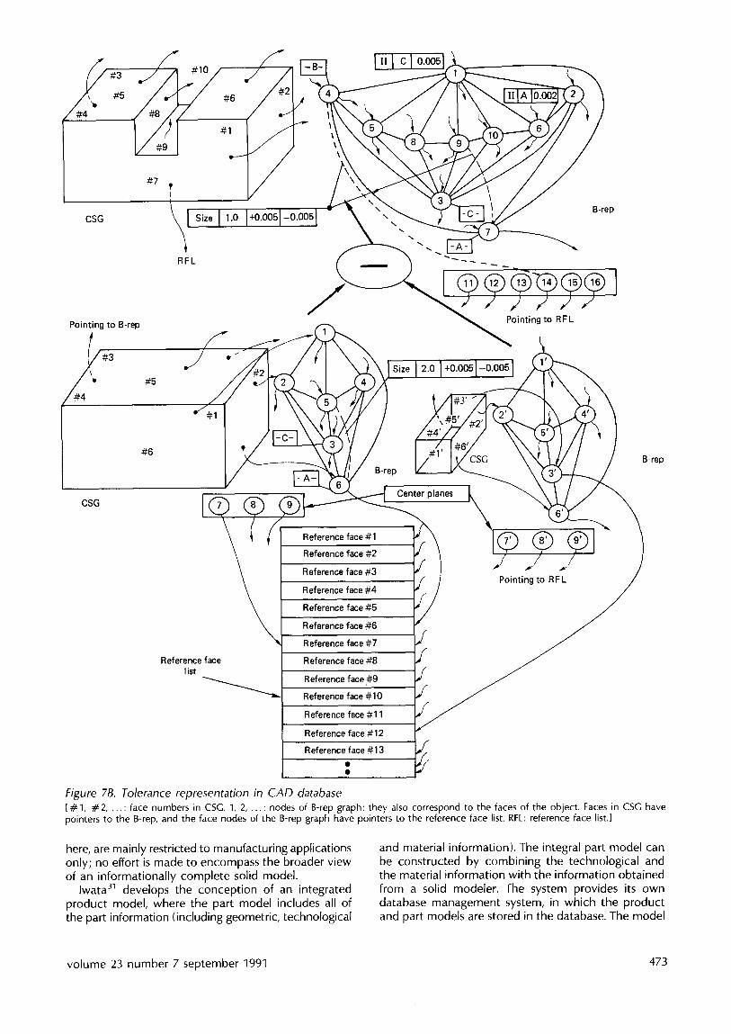
It should be noted that D&T representation is feature-based, and it needs the proper identification of 'geometric features'. Two kinds of features are involved: (a) lower-level features (such as points, lines, arcs, splines and surfaces), and (b) higher-level features, which are combinations of the lower-level features (or the combination of other higher-level features, such as holes, slots, pockets, countersinks or complex features), and which maintain certain relationships among themselves. Lower-level features are basic topological entities, and, therefore, they are well defined and unique, whereas higher-level features are design- specific, and the choice for their selection depends on the function and the context of application. For D&T implementation, this features information must be extracted or recreated from the solid model. Roy and Liu 22 showed the necessity of having a hybrid CSG/B-rep data structure for the tolerance represent- ation so that the advantages of both CSG and B-rep models can be exploited. The tolerance module is attached at the top of this hybrid structure. The user interacts with the solid model at each hierarchical level of object construction for associating tolerance and other technological information (such as material data, surface roughness etc.), rather than waiting until the entire part geometry has been defined. A process of establishing tolerance information is shown in Figure 7B. A nominal-part drawing including tolerance is shown in Figure 7A, and Figure 7B shows how the specified tolerance information has been attached to the hybrid CSG/B-rep module via a 'reference face list' (RFL). The reference face list acts as the bridge for combining the CSG and B-rep data structures. All kinds of conventional and geometrical tolerancing representation are possible in this system. This work on tolerance representation has been implemented 23'24 on the Sun workstation based on the polyhedral B-rep TWIN solid model 2s.
Gossard, Zuffante and Sakurai ~'~' have reported a similar kind of feature-based design system that uses a B-rep solid modeler. They have also used a representational scheme that combines CSG and boundary representation. They represent feature and surface information in a CSC-based graph structure called the 'object graph', which uses 'relative- position operators' (RPO) nodes to represent explicitly dimensions between features and elements of features. These RPO nodes are used in a way that is similar to the use of other regularized set-operator nodes (i.e. union, difference and intersection nodes). The object graph of the cube with a slot shown in Figure 6 is shown in Figure 8. Each RPO node defines specified dimension and tolerance constraints between two feature surfaces to determine the position of an 'operand' face with respect to a 'reference' face. For example, in Figure 8, the face a of the slot feature is constrained by the distance A from the face 5s of the cube by an RPO operator. The system has been implemented on a polyhedral solid model, and it is limited to the conventional tolerance representation only.
IGES (Initial Graphics Exchange Specification) research and development activities for the Product Data Exchange Specification (PDES) fOCUS on data modeling and representation, as well as the exchange of complete product-definition data. Part of the ~CES, PDES work includes a tolerance model that is similar, but not identical, to the PDDI model r . It addresses the representation of tolerances for B-rep-based models.
An early system, APPAS 28, exhibits a limited capability of incorporating tolerances and other surface inform- ation (which it takes from COFORM as the input in the form of a list of attributes) to derive the process sequence. SrOPP 29 also uses the same method of attaching the variational information (e.g. roundness error, positional accuracy, straightness, size tolerance, surface finish) with attributes for the 'hole specification'. In C~MS/PRO ~°, information about dimension, tolerance, surface finish and the approachability of tools is provided with each of the machining-shape elements. CJMS/PRO inherits all this information from OMS/DEC. The attempts to include tolerancing information, as described
f . l A Io.oo21
1.000 -+ 0.005
I
I I
I I I I
~ t
2.000 + 0.005
i ooo!o oo l c Io.oos
F
Figure 7A. Nominal part drawing including tolerance
472 computer-aided design
,/~#4 "t #5
#7 I
RFL
#6
#1
I" I c I o.oo ]
\
"
B-rep
Pointing to B-rep
#5
S ,1/ -"
#6
CSG
Reference face list
Pointing to RFL
Reference face # 1
Reference face #2
Reference face #3
Reference face #4
Reference face #5
Reference face #6
Reference face #7
Reference face #8
Reference face #9
Reference face # 10
Reference face #11
Reference face #12
Reference face #13
B-rep B-rep
Center planes
Pointing to RFL /
y /
f
Figure 7B. Tolerance representation in CAD database [# 1, # 2 . . . . : face numbers in CSG. 1, 2 . . . . : nodes of B-rep graph; they also correspond to the faces of the object. Faces in CSG have pointers to the g-rep, and the face nodes of the B-rep graph have pointers to the reference face list. RFL: reference face list.]
here, are mainly restricted to manufacturing applications only; no effort is made to encompass the broader view of an informationally complete solid model.
lwata 31 develops the concept ion of an integrated product model, where the part model includes all of the part information (including geometric, technological
and material information). The integral part model can be constructed by combining the technological and the material information with the information obtained from a solid modeler. The system provides its own database management system, in which the product and part models are stored in the database. The model
volume 23 number 7 september 1991 473

A B
R o o , b r . o c h " -
t form f e . t u r e
S2
,,4 S5 -"' ~ :,4
Geometric t reasoning programs
Relationship
Distance (A, B, X)
A t t r i b u t e / / ~
nominal = 10
COMET/DB
GEOMAP411 solid modelling system
Geometrical calculations Display functions
Figure 9. General framework of ( OMEl,l)~ model
Figure 8. Object graph with RPO nodes try: set-operator node, u: set-operator node, R: relative-position operator node. I
is capable of handling the model construction, the model modification, and the retrieval of the required data. Adding or changing the technological information (including nongeometric information)is performed in the model-construction stage. When the construction is finished, the system checks the possibilities of interference between the parts of the product. It is not known whether the system also includes tolerance analysis.
Other researchers 1°'{2 34 from the University of Tokyo, Japan, also address a similar kind of object- modeling scheme based on the solid modeler GEOMAP-III. By the use of a database management system (DBMS), various geometric and nongeometric data (such as physical, technological or management data) can be added, manipulated and retrieved by the definition of the appropriate types of attributes. Dimensions and tolerances are both considered to be the geometric constraints, and 1st-order predicate logic is used to represent them. The D&T model has been kept separate from the solid model, and it is represented as a kind of upper-level model on the top of the solid model. A general framework of the model is shown in Figure 9. A PROLOG-like system has been used for manipulation and to reason about the relationships and respective tolerances. It has been implemented as COMET/DB (COnceptual Modeling Experimental Tools/ Data Base) in a LISP environment. Tolerance evaluation and analysis are also supported to a limited extent.
Yu :~s'36 has proposed a variational solid-modeling system, v-SOUP, to incorporate industrial D & T practices into the boundary representation of an object, in a way that is compatible with engineering drawing. In a way that is similar to that used in the previously described product model, the D &T is also treated as the geometric constraints in V-SOLID. These constraint relationships are explicitly encoded in a graph structure
@ /--30R
@ o
_" _. 7 o.o,F__ *.°
b
Figure "10. Typical mechanical part and its dimension hierarchy; ( a) example mechanical part, ( b ) dimensioning hierarchy
called a 'dimensioning hierarchy' (see Figure 10), and both conventional and geometrical tolerances are described. The system thus needs either an exhaustive constraint describing input procedures, or a powerful algorithmic approach to capture the essential geometric- constraint patterns between different geometric entities from a system such as an engineering drawing. The input to Yu's system is the general information obtainable from the conventional drawings. The user specifies this information with the help of a design module, ED-DESIGN 37. An engineering-drawing under- standing system, EDUS, is developed to construct the V SOLID from ED-DESIGN. [t iS possible to perform the selection of the process sequence for dimensional and geometric accuracy in a way that is based on this hierarchical definition of the dimensioning scheme.
474 computer-aided design

Expert systems such as GAR138 use the D&T as input as they appear on the drawing. They are not connected with any solid modeler such as PAUL-2, ROMULUS, or GMSOLID.
Another interesting approach 39 to the representation of technological information is to define a grammar of the part, and to present its structure via a technological tree. The structure could be derived from the drawing. The implementation details of this concept are not discussed. Milacic has published another paper 4° on SAPT (the system for manufacturing process planning), where he talks about building a knowledge base containing information about (a) geometrical characteristics: shape, dimension etc., (b) functional characteristics: geometric relationships between the forms of parts: parallelism, perpendicularity, coaxiality etc., and (c) other technological characteristics. The representation technique for this knowledge base is similar to that of GARI, and is based on the production- system concept.
A commercial system, PRO/ENGINEER (a product of the Parametric Technology Corporation) 4~, supports tolerance representation in its feature-based, parametric solid modeler. This solid model uses boundary representation for object modeling. It stores all functional, topological, geometrical and other feature relationships in its database. It allows the user to establish tolerances for each dimension at any time, and it also helps in analysing tolerance stackups. Some other existing systems (such as those of Cognition, Intergraph, Computervision and CIS) also provide the facility of tolerance representation in their 2D drafting modules.
TOLERANCE SYNTHESIS AND ANALYSIS
This section presents the current status of knowledge and the use of mathematical techniques of tolerance synthesis and analysis to highlight the findings of major research work. The subject is studied from the deterministic and statistical points of view.
Tolerance synthesis
Design tolerance D&T selection in the very first design stage includes the proper transformation of the functional require- ments of design to suitable dimensions and tolerances. It evolves in four steps: (a) identification (description and quantification) of the functional requirements, (b) the identification of datum-reference-frame (DRF) features, and relationships between features that influence functional and assembly requirements, (c) the development of the functional equations (with the functional requirements as dependent variables, and the design sizes and tolerances of the dimensions affecting the functional requirements as the independent variables (from here on, those independent variables are termed the product dimensions, whereas the dependent variable is the design function)), and (d) the
determination of the economical solution of these equations. In this selection procedure, the allowable variations in the design functions are first determined from the desired functional requirements, and then the independent dimension tolerances are established. This whole developmental process of tolerance determin- ation is termed the 'tolerance-synthesis', or 'tolerance- allocation', problem.
It should be recognized that, in general, the quantification of functional requirements, and the formulation of the required design functions, are often very complex procedures. A straightforward approach is to provide all the relevant and critical dimensions with their nominal values and upper and lower limits. This is called 'worst-case' analysis, and it is a very conservative method of specifying tolerances, as the design-function variables are very unlikely to combine in this fashion in any particular product. For more realistic consideration, statistical tolerances are determined to provide statistical distributions for the design functions.
Michael and Siddal142'43 propose a 'vector-space formulation' for tolerance synthesis. In this formulation, a vector space is defined with its coordinates corresponding to the independent dimensions. 'Tolerance' and 'design' regions are then constructed in this vector space from identified tolerance variables (which define the dimensional tolerances) and design variables (which define the design functions), with their limits given. The objective is to find the upper and lower tolerance limits for the dimensions that minimize the overall manufacturing cost (which is also a function of the tolerance limits), subject to the constraint that the 'tolerance' region be completely contained within the 'design' region. They also extend the idea to statistical tolerancing. These approaches are further elaborated and incorporated in the GEOTOL prototype CAD system by Turner 21. GEOTOL uses three methods for tolerance synthesis and analysis: (a) linear programming, (b) the Monte Carlo method, and (c) the least-squares method. These methods support both worst-case and statistical tolerancing problems. As GEOTOL deals with linearized tolerance variables only, those variables are required to be selected carefully.
Farmer 14 has developed an interactive system for tolerance selection. The procedure is iterative, and a number of possible solutions need to be checked before the best one is selected. The system consists of three sets of software: the drafting program, the tolerance- technology program and the dataset program. The drafting program is used for specifying the design information of several manufacturing, assembly and inspection requirements, and for preparing drawings. The dataset program is a collection of local standards, related to size and angular tolerances, different limits and fits conditions, machining/manufacturing process accuracy etc., that are required in tolerance analysis. The tolerance-technology module performs the tolerance analyses of designs with the information available from the drafting and dataset programs.
Parkinson 44 proposes a statistical tolerance-synthesis method, where the distributions of the dimensions are derived from the sample data drawn from the intended
volume 23 number 7 september 1991 475

manufacturing processes. He develops a mathematical programming formulation, with the product cost as the objective function, and the standard deviations of the design variables, i.e. dimensions, as the decision variables for the problem. This product cost has been modeled as a function of tolerance, and it is considered to comprise two components: (a) the product processing cost, and (b) the cost due to rejected products. ]he tighter the tolerances, the higher is the manufacturing cost, with a lower number of rejected products, and vice versa. Manufacturing processes thus have a direct bearing on this optimization assignment. No constraints on tolerances are considered in this method. The particular product-cost model, as the objective function, controls the occurrence of any infeasible optimum point (i.e. infeasible small tolerances). If the infeasibility still occurs, it indicates an error in the product-cost modeling, and remodeling is necessary.
Another concept of using stochastic procedures for tolerance synthesis has been introduced by Lee and Woo4S'4~L They formulate the concept as a combinatorial optimization problem by treating the manufacturing cost as the objective function, and stackup conditions in assembly as the constraints. As the constraints are nonlinear, they have developed a technique for approximating the volume under an n-dimensional probability-density function bounded by nonlinear functions. In Reference 46, a branch-and-bound algorithm was developed for handling the automatic computation of discrete tolerances, which is combinatorially complex.
Dong and Soom 47 have developed a unidirectional, tolerance-chain analysis system for axisymmetric, rotational parts represented in a 2D CAD database. Their work, in the AU]OANA (AUtomatic TOlerance ANAlysis) program, includes the automatic retrieval of the required toterancing information from the CAD database, and the analysis of relationships between the tolerances in a specific design, including a proper tolerance-distribution scheme between all the related dimensions.
In the case of assembly tolerance accumulation, both 'worst-case' and statistical models show distinct limitations when applied to tolerance allocation. The worst-case model results in component tolerances that are tight and expensive to produce. Currently available statistical models, on the other hand, may allow looser tolerances. This is because these models assume that manufacturing variations follow a normal distribution. No skewness and bias are taken into consideration, although all manufacturing processes exhibit bias 48. Bias may be caused by machine-tool error, setup error or any other machining errors. Chase and Greenwood 72 thus propose the 'estimated mean shift' (EMS) model to deal with this expected bias for component tolerances in an assembly tolerance accumulation. As very little information is available on component distribution types in the early design stages, this EMS model provides a useful tool for tolerance allocation in several components of an assembly. In this method, the designer estimates the bias for each component by defining a zone (expressed as a fraction of the
specified tolerance range for the part dimension)about the midpoint of the tolerance range, which is the probable location of the mean of the component dimension. On the estimation of the range of the mean shift for each component, the resulting assembly tolerance is calculated by the analysis model, which includes both mean shift or bias, and part tolerance or variance.
Manufacturing tolerance D &T, thus selected and specified in the design stage, is further revised according to a detailed process plan to obtain the manufactured dimensions and tolerances of a mechanical part. The calculated manufacturing D&T are not only functions of design D&T, but also depend on the capabilities of the manufacturing processes and of the manufacturing equipment (i.e. machining errors, jig- and fixture-setting errors, workpiece-positioning errors, errors due to cutting-tool wear etc.). This suggests that a suitable transformation from design D&T to manufacturing D&T is required.
Hoffmann 49 has tried to develop a 2D tolerance- allocation model for a part, considering the operations and setting-up inaccuracies involved in a given process plan. His model can handle only those problems that fit into D models (i.e. parts made of D elements, namely 1D points and 2D edges in Euclidean space). A system of linear inequalities is first developed from the given part-tolerance specification. A set of constraints is then identified from actual operations and setup inaccuracies for the positions of several of the D elements inw)lved (that are to be machined according to a sequence plan), and this is added to the previous system of inequalities. The numerical solution of the total set of inequalities defines the resultant tolerances for the part. The main difficulty with this model lies in solving this set of inequalities.
Bourdet ~°'~1 develops another model for the optimization of unidirectional tolerance transfer from design to manufacture. The optimization procedure tries to find the optimal manufacturing dimensions from the given design dimensions, taking advantage of the maximum range of specified tolerance fields within the capabilities of the available machining. In other words, it calculates the manufacturing dimensions to be as close as possible to the limiting design tolerances. Daniel s° has implemented Bourdet's model to demonstrate the computerized tolerancing. With the input of workpiece data (the drawing of the part and its initial dimensions) and of process-plan data (the sequence and kinds of operations to be performed, the initial values of the setting of the dimensional tolerances etc.), the program carries out an iterative procedure for the process-plan optimization of tolerances. Bourdet's model is limited to 1D toterancing only. For this reason, for a given workpiece, the program needs to be executed in three directions independently.
[he AUTOANA 47 system, as mentioned above, also transforms the design D &T to the manufacturing D &T by simply translating the design coordinate system to the manufacturing coordinate system when the two coordinate origins do not coincide.
476 computer-aided design

Tolerance analysis
In tolerance analysis, the objective is to find the variability of a design function (which may be any dimension that is dependent on independent dimensions, i.e. the product dimensions, as described above) and its validity. As with tolerance synthesis, research is carried out to develop both statistical and deterministic ('worst-case') tolerance-analysis tech- niques. The commonly used statistical technique is the Monte Carlo simulation, whereas the 'variational- geometry' method, advocated by Hillyard s'S2, is the widely accepted deterministic technique.
With Monte Carlo simulation, the design-function values are generated from a large sample of dimensions with a specified statistical distribution. These design- function values are, in turn, used to calculate the statistical parameters for the design-function distribution. The main problem with this method is that it needs a large sample size to obtain a reasonable estimate of the distribution function.
A commercial package called VSAS 4 is available that uses the Monte Carlo method for tolerance analysis. VSAS needs the assembly information of the product and the dimensioning scheme for each part as input. It can automatically perform the tolerance analysis for gaps, and generate samples of dimensions and the corresponding samples of the design function. The disadvantage of the system is that it cannot extract information from an existing CAD database; the designer has to model all the details of an assembly directly in terms of relationships between the parts. A more recent work by Turner 21 uses this Monte Carlo method in the solving of tolerance-analysis problems for several simple assemblies. His work, with CEOTOL, is geometric-model-based, and the system derives all its necessary input geometric relationships from the geometric model.
In the deterministic tolerance-analysis approach, Hillyard and Braid s,s2 developed first the concept of variational geometry for analyzing the inconsistency in the specification of dimensions and tolerances in computer-aided mechanical design. The variational- geometry method is a dimension-driven, constraint- based technique. The geometry of an object is dictated by specified dimensions. The method regards dimensions as constraints between vertex geometries. The user creates a part topology and a set of dimensions from which the exact geometry is derived. The part geometry can thus be modified by changing its suitable dimension constraints. To clarify the variational-geometry technique, an example of dimensioning a 2D pentagon is shown in Figure 11. As the pentagon consists of five vertices with two degrees of freedom (DOF) for each vertex, 2 x 5, or ten, constraint equations are needed to constrain the part properly. The relationships between the dimensions of the part and its geometry (i.e. vertex coordinates, in this case) constitute the required set of constraint equations. With a given, user-defined dimension scheme, the solution of the equations yields the exact vertex geometry for the pentagon. The solution of another system of equations relating the variation in positions (or displacements) of the vertices,
i•"-•" x 3 C=40+c
~'//D=13 + 4\\ ~ l \ B=80+b
F=53°+f X\ +e
'1 • ~ A = 140+a --, Figure 11. Dimensioned pentagon 53
derived from the above constraint equations, describes the exact tolerances of the pentagon.
Hillyard's system deals mainly with polyhedral objects, and considers an object as a pin-joined, elastic wireframe covered by elastic membranes. It uses a dimension-tree to represent the dimensioning scheme, and includes the construction of a 'rigidity matrix' as a function of geometry and dimensions. The inversion of this matrix is then used to define geometry variations in terms of dimensional changes. It can determine whether a component is under-, over- or exactly defined by a given dimensioning scheme. Tolerances are treated as small dimensional changes, so that the geometry resulting from specified maximum dimensional deviations can be determined. This method treats the size, orientation and flatness tolerances only. It uses the B-rep-based BUILD solid modeler.
The work of Gossard 26, Lin ~4 and Light ss'56 extended and refined the above variational-geometry approach from the standpoint of the user interface and computational efficiency. Light' s 'symbolic-dimension- ing' system has the capability of modifying a part geometry by means of altering the numerical values of the explicitly defined dimensional constraints. Its algorithm selects the minimum set of equations and unknowns required for the solution of a given change in dimensions. It reduces the computational time considerably. Minnichelli s~ proposes a further extension of the above technique for tolerance analysis. He has considered the design of an assembly, and has concentrated on solving a composite rigidity matrix for the assembled parts. This method is also B-rep-based.
The variational-geometry technique, as discussed above, is the constraint-based approach that leads to systems of equations and inequalities. The dimension tree, as created by the dimensioning scheme of the part, defines the set of equations relating the geometry of the part to the dimensions. Tolerances are represented as allowable ranges, or as statistical distributions of the explicitly defined dimensions. As the dimensions are nonlinear functions of the vertex coordinates, they ultimately yield a system of nonlinear equations to be solved. The main drawback of the variational-geometry technique is the inherent computational difficulty of solving simultaneously this large set of nonlinear constraint equations. It requires an explicit definition of the independent constraints of the model variables. The technique is thus limited in
volume 23 number 7 september 1991 477

terms ol the practical model size, tile complexity of the part geometry, and the type of tolerance supported. Different kinds of geometric tolerances are diffi(ult to represent as a set of equations.
Aldefeld's ~: work on variation in 2D geometries is another attempt to capture the drawing-based dimensioning concept ill a geometric model. Unlike the variational-geometry technique, this work is based on geometric reasoning, in which symbol manipulation and interferencing methodology have been used in processing the geometric knowledge. The system is able to detect the consistency of the geometric model (whether it is under- or overdimensioned or redundant), and it supports the automatic generation of several variants of a given geometry with some assigned dimension values.
In addition to statistical and deterministic techniques, some researchers have also attempted to perform tolerance analysis on procedural representation of parts in CAD. Elgabry 2° postulates an effective tolerance- analysis scheme based on Requicha's 'tolerance-zone' representational technique. For any datum reference frame, a 'tolerance shell', as Elgabry calls it, can be defined that contains all possible locations of the part tolerances. Although all part tolerances are required to form the tolerance shell, only some of them really contribute to the development of the shell, depending on the tolerance hierarchy. Options are provided to slice out the tolerance shell in any prescribed direction to reveal its crosssection. Different kinds of fit, including interference and clearance, among the assembled parts of a product can readily be checked in any arbitrary direction with the help of the shell analysis. The proposed model is for a CSG solid-based tolerance representation and analysis. A working version of the model has not yet been implemented. Representing geometric tolerances as the tolerance zones, Fleming ~n studied uncertainty in assemblies of rigid parts. He introduces the concept of building networks of tolerance zones and datums for the analysis of toleranced parts and their assemblies. In the network, each arc represents a relationship implied by the tolerance specification or by contact (in the assembled condition) between the parts. It is shown how all the geometric constraints can be converted to an algebraic form, so that they can be easily manipulated to determine whether the parts of an assembly can be guaranteed to fit together.
It should be noted that tolerance analysis in a complex, 3D assembly environment is a difficult problem. Minnichelli's effort s~, as mentioned above, proves that a constraint-based approach in this case is very computationally intensive, and is almost impractical for complex cases. On the other hand, very little work has been done in the arena of procedure- driven solid models. The main problem in this case is that currently available CAD systems represent only part models, and they do not provide any global database that ( :an support the assembly-specific information of the complete product. Roy and Liu ~'~ have studied the subject in detail, and have proposed a solid-model-based assembly-data module to establish a unified framework (see Figure 12) for representing the
Assembly
f . \,,
SubassE
Assembl
Part
ements
Part_d
c(
Position : vector
Figure 12. General structure of assembly
functional and spatial relationships between the constituent parts of a product. The assembly structure allows the user to define several 'associations' between the subassemblies and the components. The nodes, marked as M, A, I and G in Figure 12, correspond to 'membership', 'aggregation', 'interaction' and 'generalization' associations, respectively, and these associations express different functional relationships between the components of a typical assembly. With the information about parts' mating relationships from the CAD data models of single parts, this assembly module largely facilitates an automatic 'tolerance- stackup' analysis and other tolerance-related checking procedures for product validity. Turner's work 21 with (;EOTOL is worth mentioning here. Instead of building a separate assembly database, 'relative-positioning operators' are used in GEOTO[ to place several parts relative to each other. They have been designated as relative-positioning nodes in GEOTOL'S generalized CSG schema (see Figure 13). In general, the action of a relative-positioning GCSG node is to position a target subtree of a model relative to a reference subtree. These subtrees may represent a part feature, part or subassembly. Turner has extended the CSG's inherent capability of representing 'bounded volumes' from single-part representation to assembly description. This
478 computer-aided design

__~ny binary operatOt t ~
LT~ ~ Modeling / ~2 ~sstG° nn iondge~ xFORM
/ , . ....
Figure 13. Use of relative-positioning operator with any binary operator
only works in a smaller domain of two-parts-at-a-time assembly conditions, and its expressability is also limited.
TOLERANCE CONTROL
Tolerance control is an important component of CAD/CAM integration. As the selection of proper design D&T affects the functionality, as well as manufacturability, of a product, the selection of manu- facturing processes, and their sequence of execution, affects process tolerance stacking. A close monitoring of the inaccuracies developed at each of the manu- facturing phases is absolutely necessary to avoid undue rejection of the part in inspection.
A computer-aided tolerance-control (CATC) system 6°'61 has been developed by the Ohio State University, USA, research group. Their method of analyzing and controlling tolerances is based on the 'tolerance-chart' technique, developed in the early 1950s. The tolerance-chart technique is the simplest method of selecting the tolerance for the resulting dimension. Machined dimensions are combined in closed chains of n dimensions, the resulting one being the result of a combination of the other n - 1 independent working dimensions. This method is limited to simple 1D cases; it is almost impractical for 2D and 3D tolerance analysis. The CATC program is iterative in nature, and uses computer graphics for information display.
The same procedure has also been adopted by Ji 62 in operational-dimensions calculation. The primitive dimensions of each operation being known, the operational tolerance of each of them is calculated from the set of blueprint dimensions and allowances, using the linear-programming technique.
An important area of tolerance control is related to the computerized process control of machine tools. One of the basic reasons for using tolerances in engineering design is uncertainty relating to the inherent inaccuracies of manufacturing equipment. When the precision and accuracy of a machine tool
cannot meet the tolerance requirements of a part design, some finishing operations are recommended, with a subsequent increase in product cost. For this reason, research into machine-tool accuracy enhancement has been proposed that aims to reduce the number of processes required 63. Donmez 64 and Ferriera 65 have reported some significant achievements in reducing machine-tool errors of one order of magnitude or better.
IMPLICATIONS OF D&T IN CAM
This section briefly discusses the implication of tolerance use with respect to the overall design/ manufacturing process. Related development areas of CAM have been identified where tolerance information is found to have profound effects on decision-making processes.
In the field of automatic process planning, the selection of machining activities/processes is greatly influenced by the constraint of preferential relationships owing to the desired machined-surface quality and product tolerance specification 66. Based on the geometrical tolerancing information, and the reference and datum feature information, the machined features (i.e. surfaces, holes, slots, pockets etc. to be produced by a particular machining operation) are ordered for machining. A modular system CEFPOS (GEnerative Frame-based Planner for Orthomorphic Shapes) 67 has demonstrated the critical role of tolerancJng information in the development of a generative process plan. This D&T information also affects the choice of the workpiece orientations during several machining conditions, and it thus indirectly influences the selection and analysis of flexible fixture design 6~'69 for an automated machining task.
D &T information is the single most important factor in automated inspection. On the receipt of a finished product (or for online process monitoring), it is the inspection module that decides on the acceptability of the product/process according to the given tolerancing information. The necessary functions of an inspection system include (a) the identification of the part feature(s) that are to be inspected, (b) the extraction of the relevant tolerancing information from the CAD database, (c) the interpretation of its meaning in terms of the relationship between the tolerances and the geometry of the part, and (d) the verification of the finished product measurements with respect to the tolerance specification. Hopp 7° describes an ongoing CAD-directed inspection project at the US Automated Manufacturing Research Facility (AMRF), which has established a framework for a direct interpretation of the design data from the CAD model in terms of inspection actions and the subsequent generation of inspection procedures. The development of another CAD-based vision system for the planning and execution of inspection has been reported by Park and Mitchell 71. This vision system is able to recognize and locate the part and its features in the 2D image based on the 3D CAD database. It generates an intermediate vision-based representation to facilitate the recognition of objects from images. The system inspects the surface
volume 23 number 7 september 1991 479

finish and shape of the object, measures each specified dimension, and compares the readings with the nominal dimension and tolerance.
R E M A R K S
In conclusion, it is appropriate to review the work so far accomplished in the different fields of D&T, and to identify the necessary directions for future cooperative study. In tolerance representation, it is obvious that the capabilities of solid models must be enhanced to incorporate both conventional and geometrical tolerances. As discussed earlier, the simple solution for tolerance representation is to hold the tolerance as an attribute of the geometry. To achieve total tolerance attribution to the geometry, every relationship between the geometric entities would have to be defined and toleranced. Therefore, future solid models must support a data structure that will allow the user to access both lower-level (i.e. points, edges, faces) and higher-level (i.e. features) geometric entities. It is also necessary to develop a mathematical foundation for tolerancing that is independent of any specific computer representation.
Another area that deserves much attention is that of finding a common base for the interpretation of tolerancing information, especially in automatic inspection. There are important computational issues (path planning, surface fitting etc.) that remain open.
The development of a suitable method for defining the optimal manufacturing tolerances to respect the requirements of the design tolerancing is a very important topic for study. Although some work has been done in this area, it has mostly been limited to 1D tolerancing only. Further extension of the prototype models (e.g. Bourdet's model)in 3D solid modeling is a necessity.
D&T control is another important issue that needs to be addressed. So far, work has been done on computerizing the old 'tolerancing-chart' technique for tolerance control, which is only suitable for conventional tolerancing. Solid-model-based control strategy, and its implementation issues, need to be addressed for online manufacturing processes to monitor all the machined surfaces within the allowable tolerance limits.
A C K N O W L E D G E M E N T S
This work was supported by the US National Science Foundation under grant CDR 8803017 to the Engineering Research Center for Intelligent Manufacturing Systems at Purdue University, USA. The authors sincerely appreciate the help of Professor D C Anderson of CADLAB, School of Mechanical Engineering, Purdue University. The authors also wish to thank an anonymous referee who provided many useful and constructive suggestions for the improvement of the paper.
R E F E R E N C E S
1 Bjorke, O Computer-Aided Publishers, Norway (1978)
Tolerancing Tapir
2 Requicha, A A G 'Mathematical models ot rigid solid objects' l echnkal l'vlen~o 28 Production Automation Project, University of Ro( hester, USA (1977)
3 'Dimensioning and tolerancing' ANSI Standard Y14.5-1982 American Society of Mechanical Engineers, USA (1982)
4 'The VSAS (Variation Simulation Analysis Software)' Applied Computer Solutions, St. Clair Shores, Michigan, USA (1984) (marketing brochure)
5 Hillyard, R C and Braid, I C 'Characterizing non-ideal shapes in terms of dimensions and tolerances' Comput. Graph. Vol 12 No 3 (1978) pp 234-238
6 Requicha, A A G 'Part and assembly description languages. Part I: Dimensioning and tolerancing' Technical Memo TM19 Production Automation Project, University of Rochester, USA (May 1977)
7 Requicha, A A G 'Representation of tolerances in solid modelling: issues and alternative approaches' in Pickett, M S and Boyse, J W (Eds.) Solid Modeling by Computers: From Theory to Applications Plenum Press, USA (1984) pp 3 22
8 Minagawa, M, Okino N and Kakazu, Y 'Automatic dimensioning on 3D solid geometry' Proc. 5th ICPE Tokyo, Japan (1984)
9 Yuen, M M, Tan, S T and Yu, K M 'Scheme for automatic dimensioning of CSG defined parts' Comput.-Aided Des. Vo120 No 3 (1988) pp 151-159
10 Suzuki, H, Kimura, F and Sata, T 'Treatment of dimensions on product modelling concept' Int. Syrup. Design & Synthesis Tokyo, Japan (Jul 1984)
11 Requicha, A A G 'Toward a theory of geometric tolerancing' Technical Memo 40 Production Auto- mation Project, University of Rochester, USA (Mar 1977)
12 Rossignac, J R 'Blending and offsetting solid models' PhD Thesis Dep. Electrical Engineering, University of Rochester, USA (1985)
13 Rossignac, J R and Requicha, A A G 'Offsetting operations in solid modelling' Comput. Aided Geom. Des. Vol 3 (1986) pp 129 148
14 Farmer, L E and Gladman, C A 'Tolerance technology - computer based analysis' ManuL Tech. CIRP Ann. Vol 35/1/1986 (1986) pp 7-10
15 Requicha, A A G and Chan, S C 'Representation of geometric features, tolerances and attributes in solid modellers based on constructive geometry' IEEE J Robot. & Automat. Vol RA-2 No 3 (1986) pp 156-166
16 Jayaraman, R and Srinivasan, V 'Geometric tolerancing. Part I: Virtual boundary requirements' IBMJ. Res. & Develop. Vo133 No 2 (1989) pp 90-104
17 Jayaraman, R and Srinivasan, V 'Geometric tolerancing. Part I1: Conditional tolerances IBM J. Res. & Develop. Vol 33 No 2 (1989)
480 computer-aided design

18 Johnson, R H 'Dimensioning and tolerancing final report' Report R-84-GM-02.2 Computer Aided Manufacturing International, USA (1985)
19 Burkett, W C 'PDDI approach to dimensioning and tolerancing a solid model' Report P-85-ASPP-02 Computer Aided Manufacturing International, USA (1985) Proc. Dimensioning & Tolerancing Workshop
20 Elgabry, A K 'A framework for a solid-based tolerance analysis' ASME Int. Computers in Engineering Conf. Chicago, USA (1986)
21 Turner, J U 'Tolerances in computer-aided geometric design' PhD Thesis Rensselaer Polytechnic Institute, USA (1987)
22 Roy, U and tiu, C R 'Feature based representational scheme of a solid modeler for providing dimension- ing and tolerancing information' Int. Conf. Manufacturing Science & Technology of the Future Massachusetts Institute of Technology, USA (Jun 1987) (also published in Int. J. Robot. & Comput.- Integr. Manut. Vol 4 No 3/4 (1988) pp 335-345)
23 Roy, U, Pollard, M D, Mantooth, K and /iu, C R 'Tolerance representation scheme in solid model: Part I' Technical Report TR-ERC 89-1 Engineering Research Center for Intelligent Manufacturing Systems, Schools of Engineering, Purdue University, USA (Jan 1989)
24 Roy, U, Mantooth, K, Pollard, M D and Liu, C R 'Tolerance representation scheme in solid model: Part I1' Technical Report TR-ERC 89-2 Engineering Research Center for Intelligent Manufacturing Systems, Schools of Engineering, Purdue University, USA (Jan 1989)
25 Mashburn, T A 'A polygonal solid modeling package' MS Thesis School of Mechanical Engineer- ing, Purdue University, USA (Dec 1987)
26 Gossard, D C, Zuffante, R P and Sakurai, H 'Representing dimensions, tolerances, and features in MCAE systems' IEEE Comput. Graph. & Applic. Vol 8 No 2 (1988) pp 51-59
27 Birchfield, E B and King, H H 'Product definition data interface (PDDI)' Proc. 1985 United States Air Force C/M Industry Conf. (1985)
28 Wysk, R A 'An automated process planning and selection program: APPAS' PhD Thesis Purdue University, USA (May 1977)
29 Choi, Byoung Kyu 'CAD/CAM compatible, tool oriented process planning for machining centers' PhD Thesis Purdue University, USA (1982)
Iwata, K, Kakino Y, Ohba, F and Sugimura, N 'Development of non-part family type computer- aided production planning system CIMS/PRO' Adv. Manuf. Tech. (1980) pp 171-184
Iwata, K and Arai, E 'Development of integrated modelling system for CAD/CAM of machine product in Advances in CAD~CAM North-Holland, Netherlands (1983)
30
31
32 Kimura, F 'GEOMAP-III: designing solids with free-form surfaces' IEEE Comput. Graph. & Applic. (1984)
33 Sata, T, Kimura, F, Suzuki, H and Fujita, T 'Designing machine assembly structure using geometric constraints in product modelling' CIRP Ann. Vol 34/1 (1985) pp 169-172
34 Kimura, F, Suzuki, H and Wingrad, / 'A uniform approach to dimensioning and tolerancing in product modeling' Preprints CAPE'86 Vol 1 (1986) pp 166-178
35 Yu, Y C, Liu, C R and Kashyap, R L 'A variational solid model for mechanical parts' ASME Winter Ann. Meet. PED Vol 21 (1986) pp 237-245
36 Yu, Yuan-chen 'A new solid modeling system for CAD/CAM integration through engineering drawing understanding' PhD Thesis Purdue University, USA (Dec 1987)
37 Yu, Y C, Liu, C R and Kashyap, R L 'ED-DESIGN: an engineering drawing based design model for computer understanding: Parts I and I1' Int. J. Robot. & Comput.-Integr. Manuf. (to appear)
38 Descotte, Y and Latombe, J 'GARI: an expert system for process planning' in Pickett, M S and Boyse, J W (Eds.) Solid Modeling for Computers: From Theory to Application Plenum Press (1984)
39 Milacic, V R 'Computer-based informatization of manufacturing engineering activities' Int. J. Prod. Res. Vol 20 No 3 (1982) pp 369-408
40 Milacic, V R 'SAPT - expert system for manufactur- ing process plan' Computer-Aided~Intelligent Process Planning, ASME Winter Ann. Meet. Miami Beach, Florida, USA (1985)
41 Pro~ENGINEER: Concepts and Capabilities Parametric Technology Corporation, Waltham, MA, USA (1987)
42 Michael, W and Siddall, J N 'The optimization problem with optimal tolerance assignment and full acceptance' ASME Trans. J. Mech. Des. Vol 103 (Oct 1981) pp 842-848
43 Michael, W and Siddall, J N 'The optimal tolerance assignment with less than full acceptance' ASME Trans. J. Mech. Des. Vo1103 (Oct 1981 ) pp 842-848
44 Parkinson, D B 'Tolerancing of component dimensions in CAD' Comput.-Aided Des. Vol 16 No 1 (1984) pp 25-32
45 Lee, W and Woo, T C 'Tolerances: their analysis and synthesis' Technical Report 86-30 Dep. Industrial and Operations Engineering, University of Michigan, USA (Dec 1986)
46 Lee, W and Woo, T C 'Optimum selection of discrete tolerances' Technical Report 87-34 Dep. Industrial and Operations Engineering, University of Michigan, USA (Dec 1987)
47 Dong, Z and Soom, A 'Automatic tolerance analysis from a CAD database' ASME 86-DET-36 Design
volume 23 number 7 september 1991 481

Enp, ineerin~ Tech. Conf. Columbus, Ohio, USA(Oct 19861
48 Mansoor, E M 'Application of probability to tolerances used in engineering design' Pro(:. I Mech. E Vol 178 Pt 1 No 1 (1963 64) pp 29 39
49 Hoffmann, P 'Analysis of tolerances and process inaccuracies in discrete part manufacturing' Comput.-Aided Des. Vol 14 No 2 (1982)
58 Daniel, F 'Development of a computer program for the optimization of tolerance transfer from design to manufacturing' MS Thesis Technion - Israel Institute of Technology, Haifa, Israel (Mar 1986)
51 Daniel, F, Weill, R and Bourdet, P 'Computer aided tolerancing and dimensioning in process planning' Manu/. Tech. CIRP Ann. Vol 35/1/1986 (1986) pp 381-- 386
52 Hillyard, R C and Braid, I C 'Analysis of dimensions and tolerances in computer-aided mechanical design' Comput.-Aided Des. Vol 10 No 3 (1978) pp 161-166
Minnichelli, M O 'A preliminary investigation of computer-aided tolerance analysis techniques' ME Thesis Rensselaer Polytechnic Institute, USA (May 1983)
Lin, V C, Gossard, D C and Light, R A 'Variational geometry in computer-aided design' Comput. Graph. Vot 15 No 3 (1981)
Light, R A 'Symbolic dimensioning in computer- aided design' MS Thesis Massachusetts Institute of Technology, USA (1980)
Light, R A and Gossard, D C 'Modification of geometric models through variational geometry' Comput.-Aided Des. Vol 14 No 4 (1982)
Aldefeld, B 'Variation of geometries based on a geometric-reasoning method' Comput.-Aided Des. Vol 20 No 3 (1988) pp 117-126
Fleming, A D 'Analysis of uncertainties and geometric tolerances in assemblies of parts' PhD Thesis University of Edinburgh, UK (1987)
Roy, U and Liu, C R 'Establishment of functional relationships between the product components in assembly data base' Technical Report TR-ERC 88-7 Engineering Research Center for Intelligent Manu- facturing Systems, Schools of Engineering, Purdue University, USA (May 1988) (also published in Comput.-Aided Des. Vol 20 No 10 (1988) pp 570 580)
Karolin, A V 'Computer aided process routing development for discrete part manufacture' MS Thesis Ohio State University, USA (1983)
61 Ahluwalia, R S and Karolin, A V 'CATC a computer aided tolerance control system'/. Manuf. Syst. Vol 3 No 2 (1984)
62 Ji, P 'Computer aided operational dimensions
53
54
55
56
57
58
59
60
calculations' Dep. Mechanical Engineering, Beijing Institute of Aeronautics and Astronat~ti(s, China
63 Liu, C R and Barash, M M 'Tile science and advanced technology for cost-effective manufacture of high precision engineering products' (Apr 1982) (proposal submitted to and funded by US Office of Naval Research)
64 Donmez, M A, Blomquest, D, Hocken, R, Liu, C R and Barash, M M 'A general methodology for machine tool accuracy enhancement by error compensation' Precision Eng. Vol 8 No 4 (1986)
65 Ferreira, P M and Liu, C R 'A method for estimating and compensating quasistatic errors of machine tools' in ASME Volume: Quality: Design, Planning and Control (Dec 1987)
66 Roy, U and Liu, C R 'An expert system approach to the machine tool sequencing and machining sequencing problems in computer aided process planning' Technical Report TR-ERC 88-'16 Engineering Research Center for Intelligent Manufacturing Systems, Schools of Engineering, Purdue University, USA (Jul 1988)
67 Vissa, N N 'A frame-based generative process planning system for machining prismatic parts' MSIE Thesis Purdue University, USA (Dec 1987)
68 Ferreira, P M and Liu, C R 'Generation of workpiece orientations for machining using a rule-based system' Robot. 8, Comput.-Inte~r. Manu/. Vol 4 No 3/4 (1988) pp 545 -555
69 Trappey, J F C and Liu, C R 'Issues of automatic fixture design in computer integrated manufacturing systems' Proc. Int. Ass()(. Sci. & Tech. Develop. Int. Symp. Robotics & Automation Santa Barbara, CA, USA (25 27 May 1988) pp 149 154
70 Hopp 'CAD - directed inspection' Presented 34th CIRP Con. Ass. Madison, Wisconsin, USA (19-25 Aug 1984)
71 Park, H D and Mitchell, O R 'CAD based planning and execution of inspection' IEEE Computer Vision & Pattern Recognition Conf. Ann Arbor, Michigan, USA (5 9 Jun 1988)
72 Chase, K W and Greenwood, W H 'Design issues in mechanical tolerance analysis' ASME Ann. Winter Meet. Advanced Topics in Manufacturing Technology Boston, MA, USA (13-18 Dec 1987)
B I B L I O G R A P H Y
Chan, S C and Voelcker, H B 'An introduction to MPL a new machining/process programming language'
Proc. Int. IEEE Conf. Robotics & Automation (Apr 1986) pp 333 344
Darbyshire, I and Davies, B J 'EXCAP: an expert generative process planning system' University of Manchester Institute of Science and Technology, UK (1984)
Eastman, C M and Preiss, K 'A review of solid shape
482 computer-aided design

modelling based on integrity verification Comput.- Aided Des. (1984) pp 66-80
Grossman, D D 'Procedural representation of three dimensional object' IBM J. Res. & Develop. Vol 20 No 6 (1976)
Hillyard, R 'The Build group of solid modellers' IEEE Comput. Graph. & Applic. (Mar 1982) pp 43-52
Iwata, K and Sugimura, N 'A knowledge based computer aided process planning system for machining parts' 16th CIRP Int. Sem. Manufacturing Systems Tokyo, Japan (1984)
Iwata, K and Sugimura, N 'An integrated CAD/CAPP system with know-hows on machining accuracies of parts' Computer-Aided~Intelligent Process Planning,
ASME Winter Ann. Meet. Miami Beach, Florida, USA (1985)
Kakino, Y, Ohba, F, Moriwaki, T and Iwata, K 'A new method of parts description for computer-aided production planning' Adv. Comput.-Aided Manuf. (1977) pp 197-213
Matsushima, K, Okada, N and Sata, T 'The integration of CAD and CAM by application of artificial intelligence techniques' CIRP Ann. Vol 31 (1982)
Requicha, A A G 'Representations for rigid solids: theory, methods and systems' ACM Comput. Surv. Vol 12 No 4 (Dec 1980) pp 437-464
Wang, K K (Ed.) 'TIPS-1 ' Sibley School of Mechanical and Aerospace Engineering, Cornell University, USA (Oct 1984) (1983 version)
volume 23 number 7 september 1991 483