review of composite sandwich structure in aeronautic
TRANSCRIPT

�
�������������������������� �������������������������������������������������������
�������������������������������������
���������������������������������������������
������ �� ��� ���� ����� ��������� ����� �������� ���� ��� � ��� ���� ��������
���������������� �������������������������������������������������
�������������������������������������������������
����������������� ��
�
�
�
�
������������ ���
an author's https://oatao.univ-toulouse.fr/26733
https://doi.org/10.1016/j.jcomc.2020.100004
Castanié, Bruno and Bouvet, Christophe and Ginot, Malo Review of composite sandwich structure in aeronautic
applications. (2020) Composites Part C: Open Access, 1. ISSN 2666-6820
Review of composite sandwich structure in aeronautic applications
Bruno CASTANIE
a , ∗ , Christophe BOUVET
a , Malo Ginot a , b
a Institut Clément Ader (ICA), Université de Toulouse, CNRS UMR 5312, INSA, ISAE Supaéro, IMT Mines Albi, UPS, Toulouse, France b Elixir Aircraft, Batiment D1 - 6 rue Aristide Bergès, 17180 Périgny, France
Keywords:
Composite Sandwich structures Aeronautic
a b s t r a c t
This paper presents a review of the issues concerning sandwich structures for aeronautical applications. The main questions raised by designers are first recalled and the complexity of sandwich structure design for aeronautics is highlighted. Then a review of applications is presented, starting with early examples from the 1930s and the Second World War. The growth in the use of sandwich materials in civil and military applications is then developed. Recent research and innovations conclude the paper.
1
1
o
(
t
t
t
[
a
a
T
l
i
o
a
f
m
a
b
s
l
a
t
a
c
f
c
o
s
l
o
u
t
f
n
t
t
d
l
t
m
I
h
1
e
a
b
s
d
b
h
h
. Fundamentals of sandwich structures for aircraft applications
.1. Definition, symmetric and asymmetric sandwiches
“The characteristic feature of the sandwich construction is the usef a multilayer skin consisting of one or more high-strength outer layersfaces) and one or more low-density inner layers (core) ”. This defini-ion, proposed by Hoff and Mautner in one of the first articles devotedo sandwich construction, in 1944 [1] , remains current and has beenaken up in various forms in the works devoted to this type of structure2–7] . Great numbers of combinations of materials and architecturesre possible today, both for the core and for the skins [8] . However, foreronautical applications, certification greatly restricts the possibilities.oday, only honeycomb cores made of Nomex, aluminium alloy or a
imited number of technical foams of very good quality are used. Sim-larly, for skins, we mainly find aluminium alloys and laminates basedn glass, carbon or Kevlar fibres. According to Guedra-Degeorges [9] ,nd also in the case of some stacking described in [10] (see also Fig. 22 ),or aeronautical applications, the skins have a thickness of less than 2m. Sandwiches fall into two categories. Symmetrical sandwiches, such
s the one illustrated in Fig. 1 , are used mainly for their resistance touckling and their bending stiffness. This type of sandwich is perfectlyuited to pressurized structures or those subjected to an aerodynamicoad and, generally speaking, it is by far the most widely used.
Another, somewhat less popular, type of sandwich is also used inircraft construction: the asymmetrical sandwich (see Fig. 2 ). As forhe classic fuselages composed of a thin skin stabilized by stiffeners,n asymmetrical sandwich is made up of a first skin in carbon laminatealled the “Working Skin ”, which takes most of the membrane stressesrom the structure. The buckling resistance of this skin is provided by a
∗ Corresponding author. E-mail address: [email protected] (B. CASTANIE).
o
s
ttps://doi.org/10.1016/j.jcomc.2020.100004
ore and a second skin designed at the minimum allowed and consistingf one or two plies of carbon or Kevlar, called the “Stabilizing Skin ”.
In addition to its particularly high mechanical characteristics, thisolution has the advantage of its junction zones being situated in pureaminate areas, thus circumventing the delicate problem of the passagef localized forces to the two skins by inserts. On the other hand, itsse is limited to non-pressurized and moderately loaded structures ofhe helicopter, light aircraft or drone type. Another fundamental dif-erence is the geometric non-linear behaviour due to the offset of theeutral line (in beam theory) with respect to the loading line located inhe middle of the working skin. This offset induces a bending momenthat is all the greater when the deflection is high. Therefore, a force /isplacement coupling occurs, which generates a typical geometric non-inear response and requires an adapted approach [11–14] . According tohe experience of the authors, this type of structure is optimal from theass point of view for non-pressurized structures subjected to low loads.
t has been applied in military and civil helicopters [16] and drones, andas been studied for the Solar Impulse planes [17] .
.2. Basic mechanics and sizing issues
Linear static ehaviour
The idea behind sandwich construction is to increase the flexion in-rtia without increasing the mass too much, as shown by D. Gay [7] in simple numerical application of 3-point bending on a stainless steeleam and then using the same beam with a 20 mm thick honeycombandwich core (see Fig. 3 ). The mass added is very low (20 %), while theeflection under bending is divided by 22 (Eq 2 of Fig. 3 ). It would haveeen divided by 90 ( 𝛿skins ) if the displacement due to transverse shearad not become preponderant because of the weakness of the modulusf the core (G core = 46 MPa). Here, we are touching on the subtlety ofandwich structures, where the expected benefits are offset by the com-

B. CASTANIE, C. BOUVET and M. Ginot
Fig. 1. Sandwich construction.
Fig. 2. Asymmetric sandwich structures.
Fig. 3. Bending calculation of a sandwich beam.
p
s
e
l
o
t
s
h
p
f
i
t/
c
l
o
k
T
i
t
m
a
b
A
c
f
i
t
c
lexities generated by a light core. All cases of linear calculations underimple static stresses have been widely developed in the literature [2–7] ,nabling sizing of the skins and the core.
The core requires special attention because the allowables are veryow, of the order of one MPa, whereas the skins generally support loadsf several hundred MPa. Therefore, the relative order of magnitude ofhe stresses in the core is 1% or less. This phenomenon is particularlyensitive in the case of curved sandwiches, e.g. for the tail booms ofelicopters or in curved fuselages [18–20] , and also for tapered areas.
Global and local buckling
As a first approximation, the increase in the bending stiffness [EI]romises a proportional increase in the critical load for buckling if we re-er to Euler’s formula: F c Euler = 𝜋
2 EI/L 2 for a simply supported beam (Ls the length of the beam). But, here again, the influence of the core haso be taken into account and the formula becomes F CSandwich = F c Euler
(1 + F c Euler /t c .G c ), where Gc is the transverse shear modulus of the
ore and tc is the thickness of the core. This significantly reduces buck-ing resistance as shown by Kassapoglou [5] . In addition, the presencef a light core also generates local buckling modes of the skin (wrin-ling) or global buckling modes controlled by the core (shear crimping).hese modes are often critical and can be the cause of premature failure
f they are not given proper consideration. They must imperatively behe object of in-depth investigation even if this involves 3D finite ele-ent modelling. For pre-sizing [4–6] , a formula ( Eq. 1 ) resulting from rudimentary analytical theory with restrictive assumptions developedy Hoff and Mautner in 1945 [21] is used for the case of wrinkling.lthough this formula gives the trends correctly, the results it providesan prove to be very far from those of experimental tests and a safetyactor is required. Zenkerts [4] proposes replacing 0.91 by 0.5 accord-ng to his experience in the naval industry. Kassapoglou [5] discusseshe relevance of this formula vs finite element modelling in the case ofomposite skins and tests, and also proposes knockdown factors. In aero-
B. CASTANIE, C. BOUVET and M. Ginot
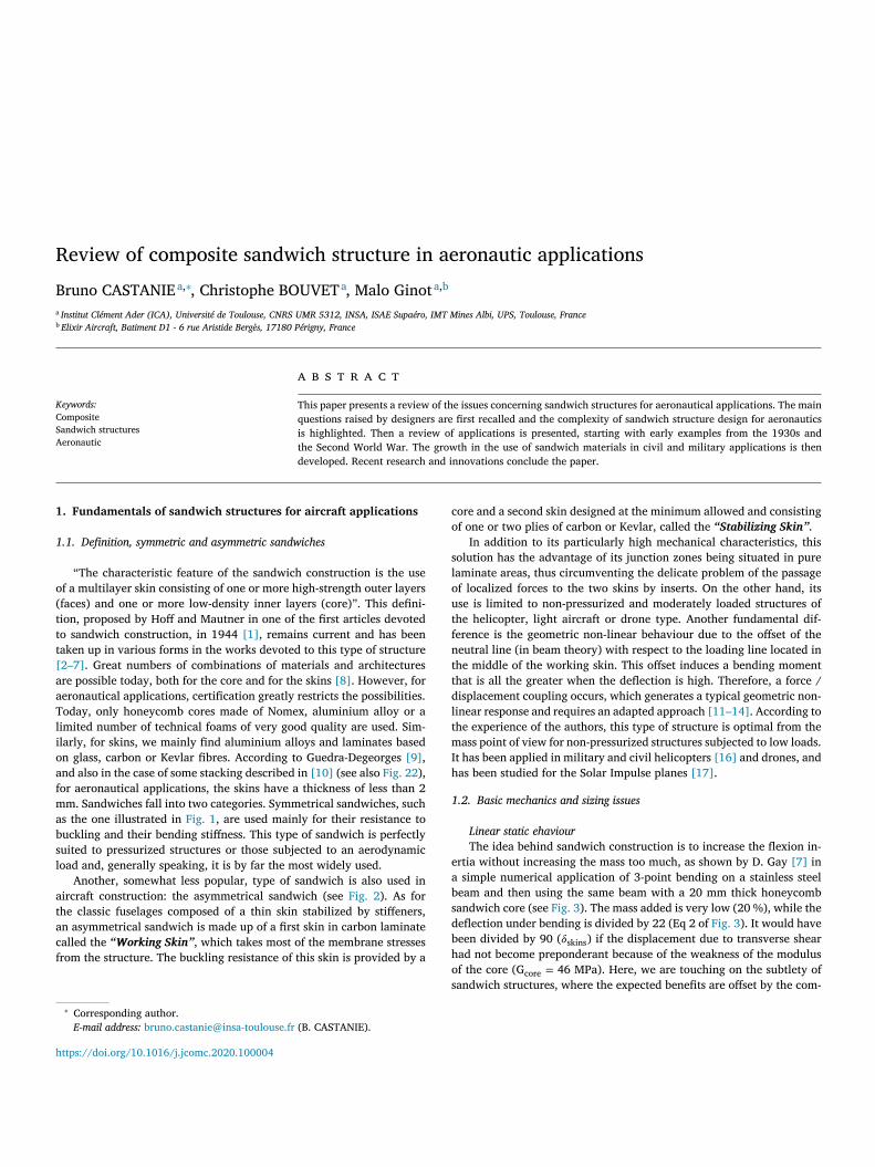
Fig. 4. Non-linear in-plane compression response of symmet- ric sandwich structures.
n
l
[
𝜎
t
d
p
t
t
c
b
p
t
t
c
t
s
n
c
w
w
i
s
w
i
t
w
4
t
u
h
t
s
t
i
r
p
r
t
c
o
t
s
I
d
i
(
(
n
H
t
w
b
l
t
1
i
a
t
l
c
a
d
s
w
7
i
f
a
d
t
s
(
I
t
q
autics, it is common to take a safety factor of 3 to allow for the intrinsicimitations of the formula and the effect of initial shape imperfections22] .
𝐶𝑟𝑖𝑡𝑖𝑐𝑎𝑙 = 0 . 91 3 √𝐸 𝑆𝑘𝑖𝑛 ⋅ 𝐸 𝐶𝑜𝑟𝑒 ⋅ 𝐺 𝐶𝑜𝑟𝑒 (1)
Even though its age, its simplicity and its relative relevance causehis formula to remain the most used, many other approaches have beeneveloped recently [23–30] , for example) and would deserve more ex-erimental and numerical evaluation. Moreover, the sizing of aeronau-ical structures currently uses a GFEM (Global Finite Element Model)hat does not capture local buckling. Therefore strategies of global / lo-al calculations [31] or approaches using analytical criteria remain toe defined. Note also that certain environmental effects, such as tem-erature, can significantly reduce the critical stress of local buckling inhe case of a sandwich with a foam core [32] , which can be critical forhe strength of light structures such as gliders or private planes.
Non linear static behaviour
In general, nonlinear calculation of sandwiches is not necessary be-ause they are subject to bending and their high stiffness means thathe structure remains under the assumption of small displacements andtrains. However, for aeronautical structures, in particular those that areot pressurized, membrane loads are dominant. This is particularly thease for asymmetrical sandwich structures loaded by the working skin,hich naturally have this behaviour [11–15] . For example, when theorking skin is loaded in compression, the stabilizing skin may break
n tension. On the other hand, it is less known that even symmetricalandwich structures can exhibit non-linear behaviour in compression,hich can strongly influence the design [13 , 33 , 34] . This case is shown
n Fig. 4 , where the software developed in [11–13] was used to computehe compression response of an asymmetrically loaded sandwich beamith a distribution of the force in the skins having the ratios 49-51% or8-52%. The strains were taken at the centre of each of the two skins andypical tulip-shaped curves were found. These curves are also obtainednder compression tests on beams or sandwich plates. This phenomenonad been identified very early by Hoff and Mautner [1] , who attributedhe nonlinear response in the tests to the loading of the skins not beingtrictly identical. This seems to be confirmed by the present computa-ion. Hoff and Mautner performed a check of dissymmetry of the strainsn the skins up to 5 times before carrying out a test to failure. For thiseason, grinding of the faces of the test pieces is recommended beforeerforming this type of test. Some authors have attributed this nonlinearesponse to an imperfect initial shape [35] which may also have con-
ributed to the phenomenon. In practice, there are several other possibleauses, such as variations in manufacturing due to small stacking errors,r differences in fibre volume and/or surface finish due to the manufac-uring method. It is also possible that differences in loading between thekins will appear if a tapered area is used.
The tulip curves are bounded by the critical force of the structure.t is classical to use linear assumptions to size the sandwich at the ULesign point (UL: Ultimate load). In Fig. 4 , this point can be found at thentersection between the linear response, in black, and the critical forcevertical line). Sizing is generally done with a damage tolerance policysee next subsection) in such a way that, at this point, the strain doesot exceed an allowable value (for example, about 6000 μstrain here).owever, with a nonlinear calculation as proposed, it can be shown
hat this value may be reached much earlier, at around 500 N/mm,ell before the critical load. Therefore a design that did not take thisehaviour into account would be wrong. This phenomenon is, however,ess noticeable for plates than for beams and naturally decreases withhe bending stiffness of the sandwich [33] .
.3. Damage tolerance
Low speed / low energy impacts, due to handling operations dur-ng manufacturing or to dropped tools during maintenance operations,re generally considered. Aeronautical sandwich structures according tohe Guedra-Degeorges definition [9] are very sensitive to impact, as areaminated structures. The impact generates a variety of damage in theore and the skins, and the residual strength can be greatly reduced. So damage tolerance policy must be followed (see Fig. 5 and [10] ), whichepends on the aircraft type (FAR or EASA from 23 to 29). Given theecurity challenges, it must be pragmatic and conservative. The methodas initially developed for the first certified primary structure: the ATR2 composite wing box [36] and is now widely used [10,37] . The ideas to distinguish undetectable damage from detectable damage. For theormer, the structure must be tolerant to damage from the pristine statend is therefore certified to ultimate loads (UL). For the second, theamage must be repaired, but a distinction is made between damagehat requires a thorough inspection to be detected (loads of the designtructure with damage: Limit Load) and those immediately detectableoften 0.85 LL). The detectability threshold, called BVID (Barely Visiblempact Damage), is determined by benchmarks with precise inspectionimes. For a detailed inspection, Airbus has set it at 0.3 mm and, for auick inspection, at 1.3 mm [38] .
B. CASTANIE, C. BOUVET and M. Ginot
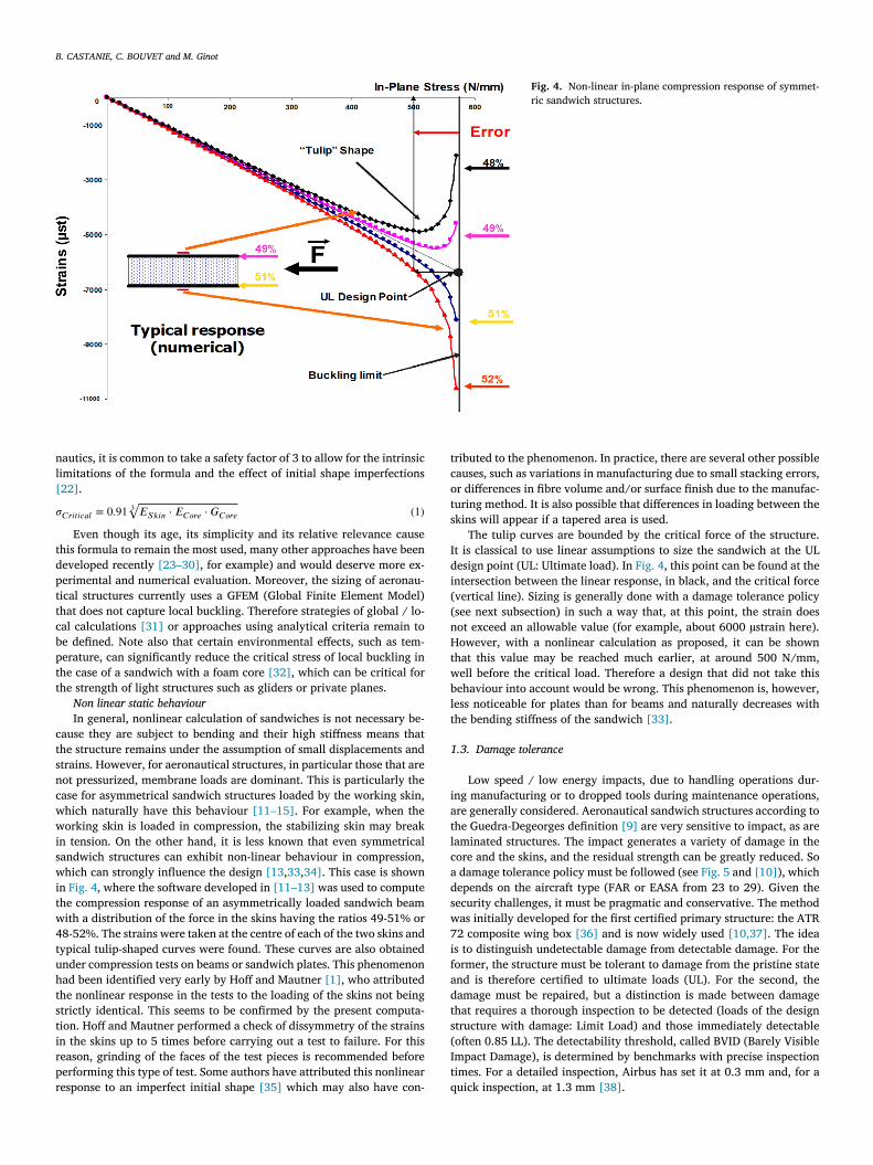
Fig. 5. Damage tolerance policy (reproduced from [10] ).
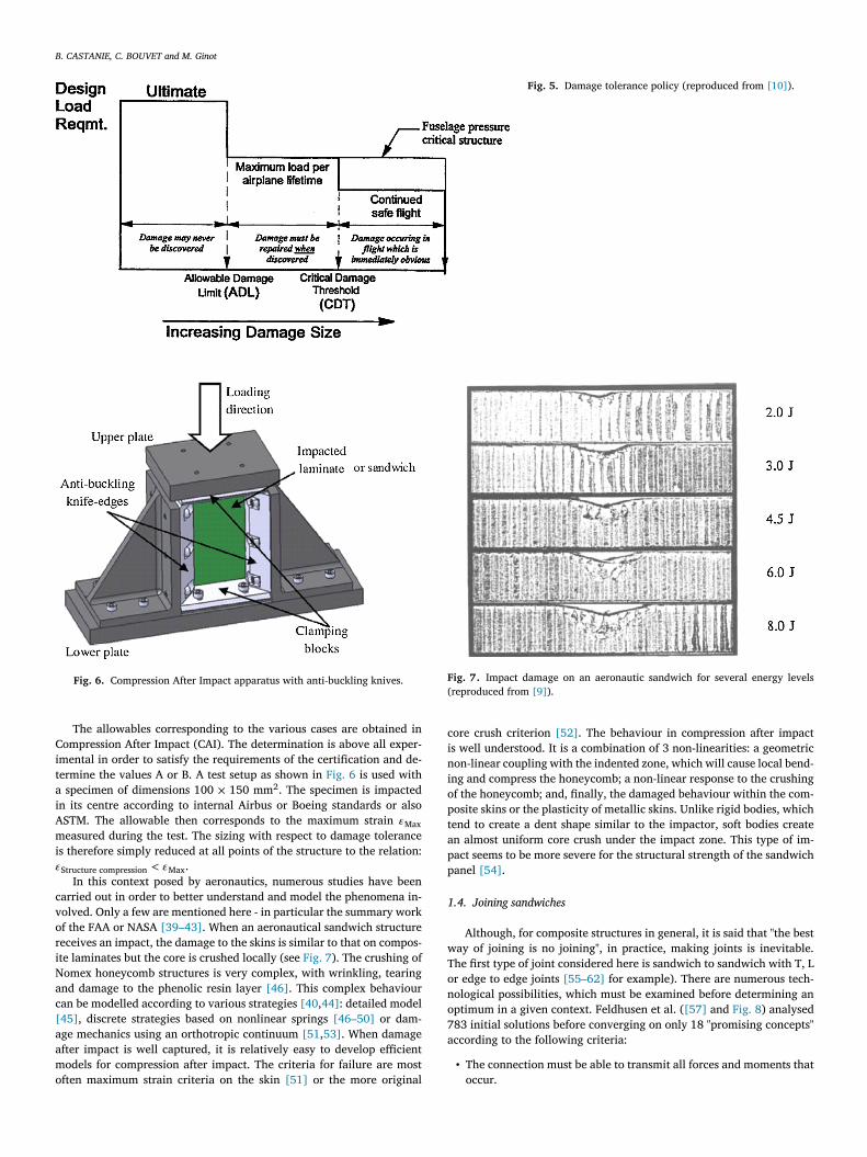
Fig. 6. Compression After Impact apparatus with anti-buckling knives.
C
i
t
a
i
Am
i
𝜀
c
v
o
r
i
N
a
c
[
a
a
m
o
Fig. 7. Impact damage on an aeronautic sandwich for several energy levels (reproduced from [9] ).
c
i
n
i
o
p
t
a
p
p
1
w
T
o
n
o
7
a
The allowables corresponding to the various cases are obtained inompression After Impact (CAI). The determination is above all exper-
mental in order to satisfy the requirements of the certification and de-ermine the values A or B. A test setup as shown in Fig. 6 is used with specimen of dimensions 100 × 150 mm
2 . The specimen is impactedn its centre according to internal Airbus or Boeing standards or alsoSTM. The allowable then corresponds to the maximum strain 𝜀 Max
easured during the test. The sizing with respect to damage tolerances therefore simply reduced at all points of the structure to the relation: Structure compression < 𝜀 Max .
In this context posed by aeronautics, numerous studies have beenarried out in order to better understand and model the phenomena in-olved. Only a few are mentioned here - in particular the summary workf the FAA or NASA [39–43] . When an aeronautical sandwich structureeceives an impact, the damage to the skins is similar to that on compos-te laminates but the core is crushed locally (see Fig. 7 ). The crushing ofomex honeycomb structures is very complex, with wrinkling, tearingnd damage to the phenolic resin layer [46] . This complex behaviouran be modelled according to various strategies [40 , 44] : detailed model45] , discrete strategies based on nonlinear springs [46–50] or dam-ge mechanics using an orthotropic continuum [51 , 53] . When damagefter impact is well captured, it is relatively easy to develop efficientodels for compression after impact. The criteria for failure are most
ften maximum strain criteria on the skin [51] or the more original
ore crush criterion [52] . The behaviour in compression after impacts well understood. It is a combination of 3 non-linearities: a geometricon-linear coupling with the indented zone, which will cause local bend-ng and compress the honeycomb; a non-linear response to the crushingf the honeycomb; and, finally, the damaged behaviour within the com-osite skins or the plasticity of metallic skins. Unlike rigid bodies, whichend to create a dent shape similar to the impactor, soft bodies createn almost uniform core crush under the impact zone. This type of im-act seems to be more severe for the structural strength of the sandwichanel [54] .
.4. Joining sandwiches
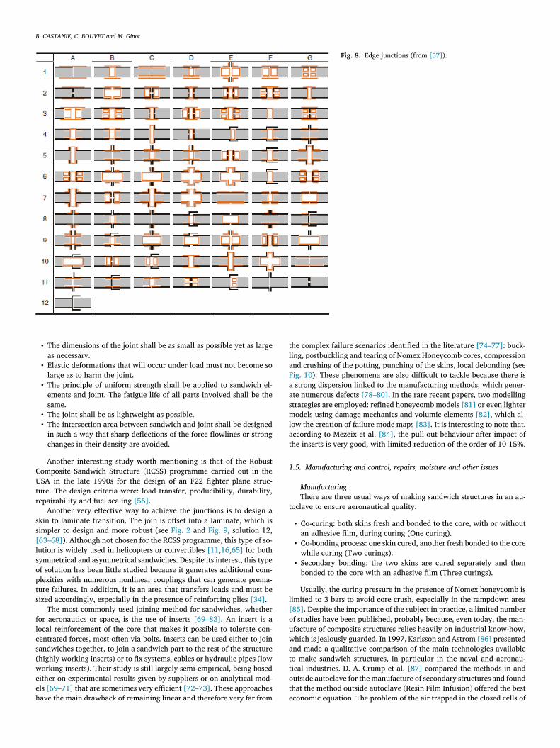
Although, for composite structures in general, it is said that "the bestay of joining is no joining", in practice, making joints is inevitable.he first type of joint considered here is sandwich to sandwich with T, Lr edge to edge joints [55–62] for example). There are numerous tech-ological possibilities, which must be examined before determining anptimum in a given context. Feldhusen et al. ( [57] and Fig. 8 ) analysed83 initial solutions before converging on only 18 "promising concepts"ccording to the following criteria:
• The connection must be able to transmit all forces and moments thatoccur.
B. CASTANIE, C. BOUVET and M. Ginot
Fig. 8. Edge junctions (from [57] ).
C
U
t
r
s
s
[
l
s
o
p
t
s
f
l
c
s
(
w
e
e
h
t
l
a
F
a
a
s
m
l
a
t
1
t
l
[
o
u
w
a
t
t
o
t
e
• The dimensions of the joint shall be as small as possible yet as largeas necessary.
• Elastic deformations that will occur under load must not become solarge as to harm the joint.
• The principle of uniform strength shall be applied to sandwich el-ements and joint. The fatigue life of all parts involved shall be thesame.
• The joint shall be as lightweight as possible. • The intersection area between sandwich and joint shall be designed
in such a way that sharp deflections of the force flowlines or strongchanges in their density are avoided.
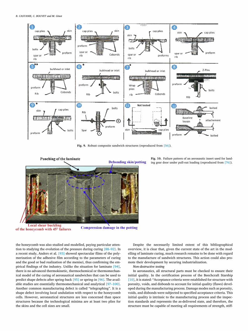
Another interesting study worth mentioning is that of the Robustomposite Sandwich Structure (RCSS) programme carried out in theSA in the late 1990s for the design of an F22 fighter plane struc-
ure. The design criteria were: load transfer, producibility, durability,epairability and fuel sealing [56] .
Another very effective way to achieve the junctions is to design akin to laminate transition. The join is offset into a laminate, which isimpler to design and more robust (see Fig. 2 and Fig. 9 , solution 12,63–68] ). Although not chosen for the RCSS programme, this type of so-ution is widely used in helicopters or convertibles [11 , 16 , 65] for bothymmetrical and asymmetrical sandwiches. Despite its interest, this typef solution has been little studied because it generates additional com-lexities with numerous nonlinear couplings that can generate prema-ure failures. In addition, it is an area that transfers loads and must beized accordingly, especially in the presence of reinforcing plies [34] .
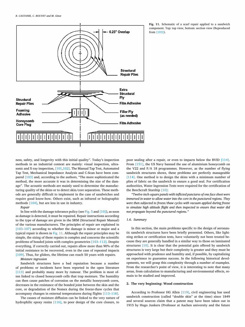
The most commonly used joining method for sandwiches, whetheror aeronautics or space, is the use of inserts [69–83] . An insert is aocal reinforcement of the core that makes it possible to tolerate con-entrated forces, most often via bolts. Inserts can be used either to joinandwiches together, to join a sandwich part to the rest of the structurehighly working inserts) or to fix systems, cables or hydraulic pipes (loworking inserts). Their study is still largely semi-empirical, being based
ither on experimental results given by suppliers or on analytical mod-ls [69–71] that are sometimes very efficient [72–73] . These approachesave the main drawback of remaining linear and therefore very far from
he complex failure scenarios identified in the literature [74–77] : buck-ing, postbuckling and tearing of Nomex Honeycomb cores, compressionnd crushing of the potting, punching of the skins, local debonding (seeig. 10 ). These phenomena are also difficult to tackle because there is strong dispersion linked to the manufacturing methods, which gener-te numerous defects [78–80] . In the rare recent papers, two modellingtrategies are employed: refined honeycomb models [81] or even lighterodels using damage mechanics and volumic elements [82] , which al-
ow the creation of failure mode maps [83] . It is interesting to note that,ccording to Mezeix et al. [84] , the pull-out behaviour after impact ofhe inserts is very good, with limited reduction of the order of 10-15%.
.5. Manufacturing and control, repairs, moisture and other issues
Manufacturing
There are three usual ways of making sandwich structures in an au-oclave to ensure aeronautical quality:
• Co-curing: both skins fresh and bonded to the core, with or withoutan adhesive film, during curing (One curing).
• Co-bonding process: one skin cured, another fresh bonded to the corewhile curing (Two curings).
• Secondary bonding: the two skins are cured separately and thenbonded to the core with an adhesive film (Three curings).
Usually, the curing pressure in the presence of Nomex honeycomb isimited to 3 bars to avoid core crush, especially in the rampdown area85] . Despite the importance of the subject in practice, a limited numberf studies have been published, probably because, even today, the man-facture of composite structures relies heavily on industrial know-how,hich is jealously guarded. In 1997, Karlsson and Astrom [86] presentednd made a qualitative comparison of the main technologies availableo make sandwich structures, in particular in the naval and aeronau-ical industries. D. A. Crump et al. [87] compared the methods in andutside autoclave for the manufacture of secondary structures and foundhat the method outside autoclave (Resin Film Infusion) offered the bestconomic equation. The problem of the air trapped in the closed cells of
B. CASTANIE, C. BOUVET and M. Ginot
Fig. 9. Robust composite sandwich structures (reproduced from [56] ).
Fig. 10. Failure pattern of an aeronautic insert used for land- ing gear door under pull-out loading (reproduced from [76] ).
t
t
a
m
a
p
t
i
p
a
A
s
c
s
t
o
e
t
m
i
[
p
o
v
i
t
he honeycomb was also studied and modelled, paying particular atten-ion to studying the evolution of the pressure during curing [88–92] . In recent study, Anders et al. [93] showed spectacular films of the poly-erization of the adhesive film according to the parameters of curing
nd the good or bad realization of the menisci, thus confirming the em-irical findings of the industry. Unlike the situation for laminate [94] ,here is no advanced thermokinetic, thermochemical or thermomechan-cal model of the curing of aeronautical sandwiches that can be used toredict shape defects after spring-back [95] or spring-in [96] . The avail-ble studies are essentially thermomechanical and analytical [97–100] .nother common manufacturing defect is called “telegraphing ”. It is ahape defect involving local undulation with respect to the honeycombells. However, aeronautical structures are less concerned than spacetructures because the technological minima are at least two plies for
he skins and the cell sizes are small. sDespite the necessarily limited extent of this bibliographicalverview, it is clear that, given the current state of the art in the mod-lling of laminate curing, much research remains to be done with regardo the manufacture of sandwich structures. This action could also pro-ote their development by securing industrialization.
Non-destructive testing
In aeronautics, all structural parts must be checked to ensure theirnitial quality. In the certification process of the Beechcraft Starship10] , it is stated: “Acceptance criteria were established for structure withorosity, voids, and disbonds to account for initial quality (flaws) devel-ped during the manufacturing process. Damage modes such as porosity,oids, and disbonds were subjected to specified acceptance criteria. Thisnitial quality is intrinsic to the manufacturing process and the inspec-ion standards and represents the as-delivered state, and therefore, thetructure must be capable of meeting all requirements of strength, stiff-
B. CASTANIE, C. BOUVET and M. Ginot
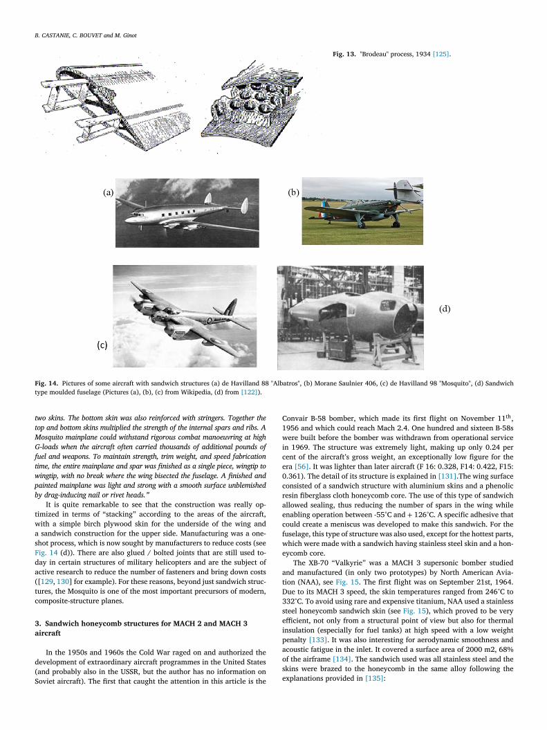
Fig. 11. Schematic of a scarf repair applied to a sandwich component. Top: top view, bottom: section view (Reproduced from [103] ).
n
m
s
T
p
m
a
t
o
r
m
a
t
o
[
t
s
p
e
i
[
o
[
t
c
d
c
a
h
p
F
t
s
[
p
a
t
i
w
t
n
1
t
n
c
s
s
a
o
o
F
a
m
2
s
a
ess, safety, and longevity with this initial quality ”. Today’s inspectionethods in an industrial context are mainly: visual inspection, ultra-
onic and X-ray inspection, [101 , 102] . The Manual Tap Test, Automatedap Test, Mechanical Impedance Analysis and C-Scan have been com-ared [103] and, according to the authors, “The more sophisticated theethod, the more accurate it was in determining the size of the dam-
ge ”. The acoustic methods are mainly used to determine the manufac-uring quality of the skins or to detect skin/core separation. These meth-ds are generally difficult to implement in the case of sandwiches andequire good know-how. Others exist, such as infrared or holographicethods [104] , but are less in use in industry.
Repair
In line with the damage tolerance policy (see Fig. 5 and [10] ), as soons damage is detected, it must be repaired. Repair instructions accordingo the type of damage are given in the SRM (Structural Repair Manual)f the various manufacturers. The principles of repair are explained in103–107] according to whether the damage is minor or major and aypical repair is shown in Fig. 11 . Although the repair principles may beimple, the sizing of these repairs is complex and concerns the scientificroblems of bonded joints with complex geometries [103–112] . Despiteverything, if correctly carried out, repairs allow more than 90% of thenitial resistance to be recovered, even in the case of repeated impacts109] . Thus, for gliders, the lifetime can reach 50 years with repairs.
Moisture ingression
Sandwich structures have a bad reputation because a numberf problems or incidents have been reported in the open literature113] and probably many more by rumour. The problem is most of-en linked to closed honeycomb cells that trap moisture. The humidityan then cause patches of corrosion on the metallic honeycomb cores,ecreases in the resistance of the bonded joint between the skin and theore, or degradation of the Nomex during the freeze-thaw cycles thatccompany changes in external temperatures during flights [113–118] .
The causes of moisture diffusion can be linked to the very nature ofydrophilic epoxy resins [116] , to poor design of the core closure, to
1
oor sealing after a repair, or even to impacts below the BVID [114] .rom [151] , the US Navy banned the use of aluminium honeycomb onhe V22 and F/A 18 programmes. However, as the number of flyingandwich structures shows, these problems are perfectly manageable114] . One method is to design the skins with a minimum number oflies of fabric on the sandwich to ensure a good seal. For certificationuthorities, Water Ingression Tests were required for the certification ofhe Beechcraft Starship [10] :
“Twelve-inch-square panels with inflicted punctures of one face sheet were
mmersed in water to allow water into the core in the punctured regions. They
ere then subjected to freeze/thaw cycles with vacuum applied during freeze
o simulate high altitude flight and then inspected to ensure that water did
ot propagate beyond the punctured regions. ”
.6. Summary
In this section, the main problems specific to the design of aeronau-ic sandwich structures have been briefly presented. Others, like light-ing strikes or certification tests, have voluntarily not been treated be-ause they are generally handled in a similar way to those on laminatedtructures [10] . It is clear that the potential gain offered by sandwichtructures is very large but their complexity is greater and they must bepproached with prudence and humility and, if possible, by capitalizingn experience to guarantee success. In the following historical devel-pments, we will grasp this complexity through a number of examples.rom the researcher’s point of view, it is interesting to note that manyreas, from calculation to manufacturing and environmental effects, re-ain to be studied and improved.
. The very beginning: Wood construction
According to Professor HG Allen [119] , civil engineering has usedandwich construction (called “double skin ” at the time) since 1849nd several sources claim that a patent may have been taken out in915 by Hugo Junkers (Professor at Aachen university and the future

B. CASTANIE, C. BOUVET and M. Ginot
Fig. 12. Glider wood sandwich construction (reproduced from [123] ).
f
e
o
b
t
d
m
T
s
m
p
T
o
t
p
m
n
r
fw
fi
a
c
r
b
i
s
h
s
c
t
b
h
p
B
I
i
e
c
b
p
d
i
a
D
s
w
a
t
a
b
a
8
w
H
p
I
1
s
c
[
a
9
o
m
w
s
d
w
v
s
S
[
H
p
b
(
p
f
w
r
i
f
t
m
t
h
o
ather of the Ju-52) for a sandwich structure with honeycomb core. How-ver, as far as the authors know, he never went on to exploit it for hiswn aircraft [120] . In 1924, a patent for a glider fuselage was filedy Theodore Von Karman himself and P. Stock [121] and is cited inhe papers of Nicholas J. Hoff [1 , 122 , 123] . According to Hoff, “It in-icates that the gliding society of the Polytechnic Institute of Aachenust have planned, if not built, a fuselage having a sandwich skin ”.hus, gliders were probably the first flying structures to have a fullandwich construction. The required criteria were: aerodynamic refine-ent, light weight, inexpensive production, sturdiness and ease of re-air, and also manufacturing ability to make double curved structures.he manufacturing process used a wooden mould and a large numberf clamps. The mould was lined with metal resistance heating pads,he temperature of which was controlled by a thermostat. A uniformressure was maintained by means of a vacuum bag to cure the ther-osetting phenol-formaldehyde glue that was used. It is important toote here that the first development of a wood sandwich structure wasooted in the application of efficient glues for bonding woods. The urea-ormaldehyde adhesive known by the commercial name of “Aerolite ”as developed by De Bruyne [124] , who would later invent the Reduxlms.
A sandwich D-Spar and a typical fuselage of a glider of the timere shown Fig. 12 . It is remarkable that the advantages of sandwich oromposite structures, such as the simplification of the design and theeduction in the number of parts, were already highlighted as indicatedy the sleek design of the D-Spar. According to Hoff and Mautner “an
nteresting design feature is the local reinforcement of the structure to with-
tand the concentrated loads imposed by towing and landing. Back of towing
ook A and above skid C in the region marked B, the core of the sandwich
kin is spruce. The density of this spruce insert is changed through the appli-
ation of compression during the manufacturing process in such a way that
he specific weight is 1.2 near hook A while it decreases gradually to 0.5 near
ulkhead D. Elsewhere the core is balsa with its thickness decreasing from the
ighly stressed bottom portion of the fuselage toward the lightly stressed top
ortion. The wing is attached to the two main frames D and E of the fuselage.
etween the frames two beams F are arranged to support the landing wheel ”.t should be noted that the example given in [123] and reproduced heres not dated and is probably related to Second-World-War or earlier glid-rs. Today’s glider structures are still made with thin sandwich but theores are of foam and the skins of glass or carbon.
Some parts of aircraft were punctually manufactured with wood-ased sandwich structures in the nineteen-thirties. Hoff [122] reportedontoons of the Sundstedt plane developed in the USA in 1919, the Sky-ine aileron in 1939, the fuselage of the De Havilland Comet (DH 88)n 1934 and De Havilland Albatros in 1938 and the wings of a Frenchirplane developed by SE. Mautner in 1938. The De Havilland AlbatrosH 91 was a four-engine transatlantic mail plane able to carry 22 pas-
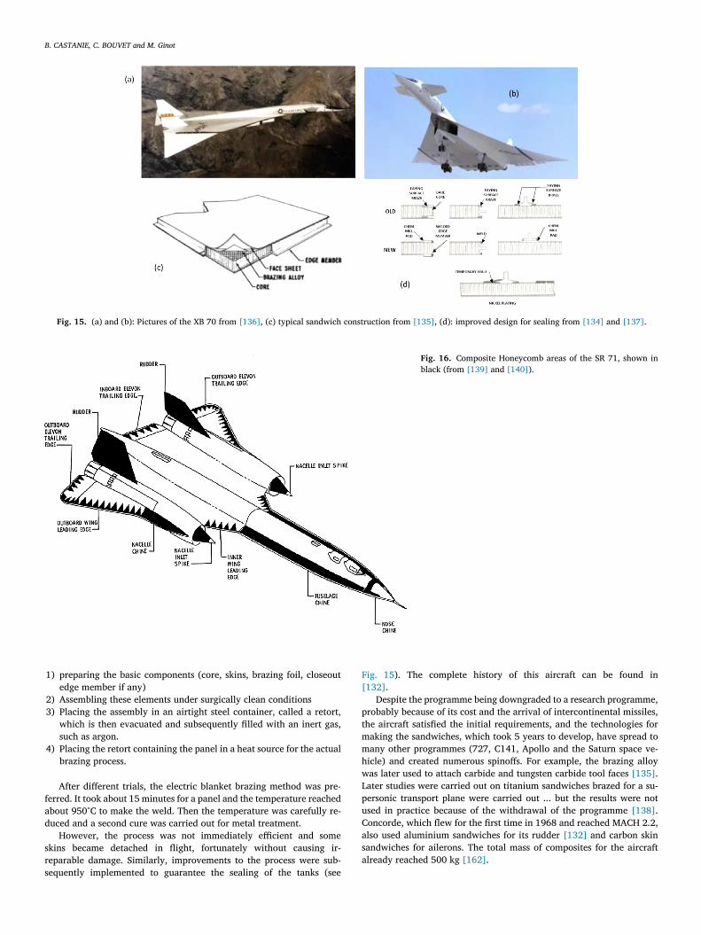
engers, which made its first flight in 1937 (see Fig. 14 (a)). The sand-ich was designed with plywood skins and a balsa core. For the Frenchircraft, a French patent, “the Brodeau process ”, dating from 1934 is de-ailed in [125] (see Fig. 13 ). The sandwich is made up of 2 plywood skinsnd a cork core drilled with holes to optimize the mass. This process iselieved to have been applied to a Lignel aircraft in 1938.
It is not well known that the Morane-Saulnier 406 (see Fig. 14 (b)), single-seat interceptor fighter built France, which first flew on August
th , 1935, was designed with a wing made of “Plymax ”. This is a sand-ich structure with aluminium skins and an Oukoumé plywood core.owever, this technological choice was complex from a manufacturingoint of view and penalized the ramp-up in production of the aircraft.n addition, this aircraft proved to be inferior to the Messerschmitt Bf09 in the Battle of France in 1940. This type of plywood/aluminiumtructure has also been rediscovered recently and shows very good me-hanical qualities [126] in compression and compression after impact127] .
The plane that is most famous and most cited for its plywood skinnd balsa core sandwich structures is the de Havilland “Mosquito ” DH8 (see Fig. 14 (c)). It turned out to be one of the best planes of the Sec-nd World War, both for its pure performance and for the extraordinaryissions it achieved. As Professor HG Allen notes in [119] , it is oftenrongly presented as the first plane with primary parts in sandwich
tructures. However, its design comes from the experience acquired bye Havilland with the DH 88 and DH 91. It is very similar to the DH 88,hich had been proposed to the British War Ministry in a light bomberersion but refused. However, de Havilland persisted and showed fore-ight in anticipating the aluminium shortage that occurred during theecond World War.
The detailed design of the structure is perfectly explained in128] and reproduced here: “Like the Comet and Albatross mainplanes, de
avilland constructed Mosquito mainplanes out of shaped pieces of wood and
lywood cemented together with Casein glue. Approximately 30,000 small,
rass wood screws also reinforced the glue joints inside a Mosquito mainplane
another 20,000 or so screws reinforced glue joints in the fuselage and em-
ennage). The internal mainplane structure consisted of plywood box spars
ore and aft. Plywood ribs and stringers braced the gaps between the spars
ith space left over for fuel tanks and engine and flight controls. Plywood
ibs and skins also formed the mainplane leading edges and flaps but de Hav-
lland framed-up the ailerons from aluminium alloy and covered them with
abric. Sheet metal skins enclosed the engines and metal doors closed over
he main wheel wells when the pilot retracted the landing gear. To cover the
ainplane structure and add strength, de Havilland woodworkers built two
op mainplane skins and one bottom skin using birch plywood. The top skins
ad to carry the heaviest load so the designers also beefed them up with birch
r Douglas fir stringers cut into fine strips and glued and screwed between the
B. CASTANIE, C. BOUVET and M. Ginot
Fig. 13. "Brodeau" process, 1934 [125] .
Fig. 14. Pictures of some aircraft with sandwich structures (a) de Havilland 88 "Albatros", (b) Morane Saulnier 406, (c) de Havilland 98 "Mosquito", (d) Sandwich type moulded fuselage (Pictures (a), (b), (c) from Wikipedia, (d) from [122] ).
t
t
M
G
f
t
w
p
b
t
w
a
s
F
d
a
(
t
c
3
a
d
(
S
C
1
w
i
c
e
0
c
r
a
e
c
f
w
e
a
t
D
3
s
e
i
p
a
o
s
e
wo skins. The bottom skin was also reinforced with stringers. Together the
op and bottom skins multiplied the strength of the internal spars and ribs. A
osquito mainplane could withstand rigorous combat manoeuvring at high
-loads when the aircraft often carried thousands of additional pounds of
uel and weapons. To maintain strength, trim weight, and speed fabrication
ime, the entire mainplane and spar was finished as a single piece, wingtip to
ingtip, with no break where the wing bisected the fuselage. A finished and
ainted mainplane was light and strong with a smooth surface unblemished
y drag-inducing nail or rivet heads. ”
It is quite remarkable to see that the construction was really op-imized in terms of “stacking ” according to the areas of the aircraft,ith a simple birch plywood skin for the underside of the wing and sandwich construction for the upper side. Manufacturing was a one-hot process, which is now sought by manufacturers to reduce costs (seeig. 14 (d)). There are also glued / bolted joints that are still used to-ay in certain structures of military helicopters and are the subject ofctive research to reduce the number of fasteners and bring down costs[ 129 , 130 ] for example). For these reasons, beyond just sandwich struc-ures, the Mosquito is one of the most important precursors of modern,omposite-structure planes.
. Sandwich honeycomb structures for MACH 2 and MACH 3
ircraft
In the 1950s and 1960s the Cold War raged on and authorized theevelopment of extraordinary aircraft programmes in the United Statesand probably also in the USSR, but the author has no information onoviet aircraft). The first that caught the attention in this article is the
onvair B-58 bomber, which made its first flight on November 11 th ,956 and which could reach Mach 2.4. One hundred and sixteen B-58sere built before the bomber was withdrawn from operational service
n 1969. The structure was extremely light, making up only 0.24 perent of the aircraft’s gross weight, an exceptionally low figure for thera [56] . It was lighter than later aircraft (F 16: 0.328, F14: 0.422, F15:.361). The detail of its structure is explained in [131] .The wing surfaceonsisted of a sandwich structure with aluminium skins and a phenolicesin fiberglass cloth honeycomb core. The use of this type of sandwichllowed sealing, thus reducing the number of spars in the wing whilenabling operation between -55°C and + 126°C. A specific adhesive thatould create a meniscus was developed to make this sandwich. For theuselage, this type of structure was also used, except for the hottest parts,hich were made with a sandwich having stainless steel skin and a hon-
ycomb core. The XB-70 “Valkyrie ” was a MACH 3 supersonic bomber studied
nd manufactured (in only two prototypes) by North American Avia-ion (NAA), see Fig. 15 . The first flight was on September 21st, 1964.ue to its MACH 3 speed, the skin temperatures ranged from 246°C to32°C. To avoid using rare and expensive titanium, NAA used a stainlessteel honeycomb sandwich skin (see Fig. 15 ), which proved to be veryfficient, not only from a structural point of view but also for thermalnsulation (especially for fuel tanks) at high speed with a low weightenalty [133] . It was also interesting for aerodynamic smoothness andcoustic fatigue in the inlet. It covered a surface area of 2000 m2, 68%f the airframe [134] . The sandwich used was all stainless steel and thekins were brazed to the honeycomb in the same alloy following thexplanations provided in [135] :
B. CASTANIE, C. BOUVET and M. Ginot
Fig. 15. (a) and (b): Pictures of the XB 70 from [136] , (c) typical sandwich construction from [135] , (d): improved design for sealing from [134] and [137] .
Fig. 16. Composite Honeycomb areas of the SR 71, shown in black (from [139] and [140] ).
f
a
d
s
r
s
F
[
p
t
m
m
h
w
L
p
u
C
a
s
a
1) preparing the basic components (core, skins, brazing foil, closeoutedge member if any)
2) Assembling these elements under surgically clean conditions 3) Placing the assembly in an airtight steel container, called a retort,
which is then evacuated and subsequently filled with an inert gas,such as argon.
4) Placing the retort containing the panel in a heat source for the actualbrazing process.
After different trials, the electric blanket brazing method was pre-erred. It took about 15 minutes for a panel and the temperature reachedbout 950°C to make the weld. Then the temperature was carefully re-uced and a second cure was carried out for metal treatment.
However, the process was not immediately efficient and somekins became detached in flight, fortunately without causing ir-eparable damage. Similarly, improvements to the process were sub-equently implemented to guarantee the sealing of the tanks (see
ig. 15 ). The complete history of this aircraft can be found in132] .
Despite the programme being downgraded to a research programme,robably because of its cost and the arrival of intercontinental missiles,he aircraft satisfied the initial requirements, and the technologies foraking the sandwiches, which took 5 years to develop, have spread toany other programmes (727, C141, Apollo and the Saturn space ve-icle) and created numerous spinoffs. For example, the brazing alloyas later used to attach carbide and tungsten carbide tool faces [135] .ater studies were carried out on titanium sandwiches brazed for a su-ersonic transport plane were carried out ... but the results were notsed in practice because of the withdrawal of the programme [138] .oncorde, which flew for the first time in 1968 and reached MACH 2.2,lso used aluminium sandwiches for its rudder [132] and carbon skinandwiches for ailerons. The total mass of composites for the aircraftlready reached 500 kg [162] .
B. CASTANIE, C. BOUVET and M. Ginot
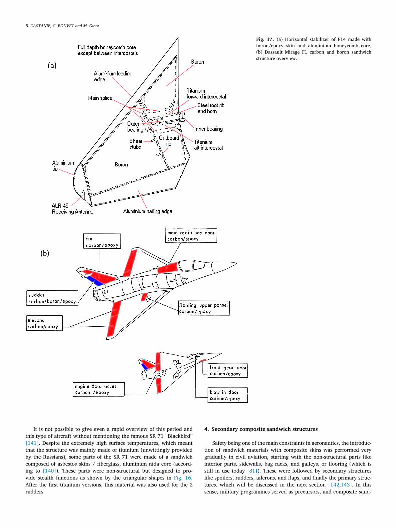
Fig. 17. (a) Horizontal stabilizer of F14 made with boron/epoxy skin and aluminium honeycomb core, (b) Dassault Mirage F1 carbon and boron sandwich structure overview.
t[
t
b
c
i
v
A
r
4
t
g
i
s
l
t
It is not possible to give even a rapid overview of this period andhis type of aircraft without mentioning the famous SR 71 “Blackbird ”141] . Despite the extremely high surface temperatures, which meanthat the structure was mainly made of titanium (unwittingly providedy the Russians), some parts of the SR 71 were made of a sandwichomposed of asbestos skins / fiberglass, aluminum nida core (accord-ng to [140] ). These parts were non-structural but designed to pro-ide stealth functions as shown by the triangular shapes in Fig. 16 .fter the first titanium versions, this material was also used for the 2
udders. s. Secondary composite sandwich structures
Safety being one of the main constraints in aeronautics, the introduc-ion of sandwich materials with composite skins was performed veryradually in civil aviation, starting with the non-structural parts likenterior parts, sidewalls, bag racks, and galleys, or flooring (which istill in use today [81] ). These were followed by secondary structuresike spoilers, rudders, ailerons, and flaps, and finally the primary struc-ures, which will be discussed in the next section [142 , 143] . In thisense, military programmes served as precursors, and composite sand-
B. CASTANIE, C. BOUVET and M. Ginot
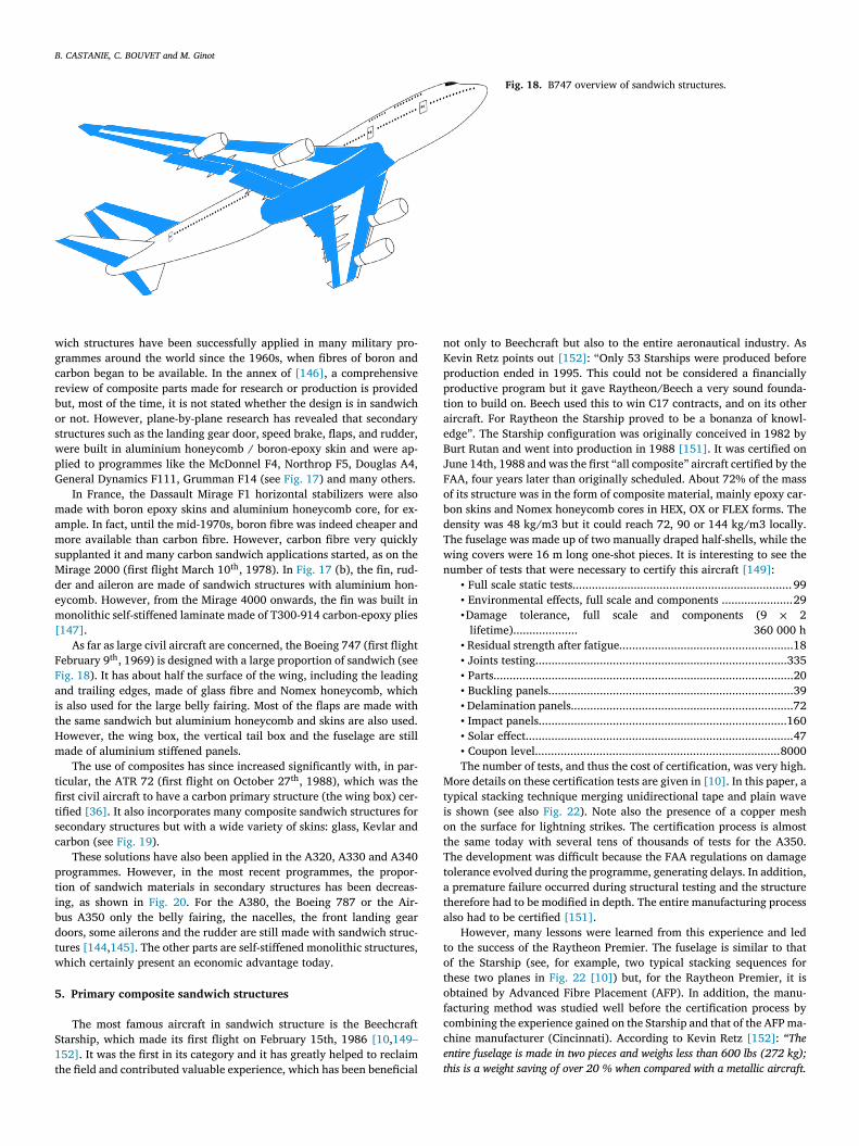
Fig. 18. B747 overview of sandwich structures.
w
g
c
r
b
o
s
w
p
G
m
a
m
s
M
d
e
m
[
F
F
a
i
t
H
m
t
fi
t
s
c
p
t
i
b
d
t
w
5
S1
t
n
K
p
p
t
a
e
B
J
F
o
b
d
T
w
n
M
t
i
o
t
T
t
a
t
a
t
o
t
o
f
c
c
e
t
ich structures have been successfully applied in many military pro-rammes around the world since the 1960s, when fibres of boron andarbon began to be available. In the annex of [146] , a comprehensiveeview of composite parts made for research or production is providedut, most of the time, it is not stated whether the design is in sandwichr not. However, plane-by-plane research has revealed that secondarytructures such as the landing gear door, speed brake, flaps, and rudder,ere built in aluminium honeycomb / boron-epoxy skin and were ap-lied to programmes like the McDonnel F4, Northrop F5, Douglas A4,eneral Dynamics F111, Grumman F14 (see Fig. 17 ) and many others.
In France, the Dassault Mirage F1 horizontal stabilizers were alsoade with boron epoxy skins and aluminium honeycomb core, for ex-
mple. In fact, until the mid-1970s, boron fibre was indeed cheaper andore available than carbon fibre. However, carbon fibre very quickly
upplanted it and many carbon sandwich applications started, as on theirage 2000 (first flight March 10 th , 1978). In Fig. 17 (b), the fin, rud-
er and aileron are made of sandwich structures with aluminium hon-ycomb. However, from the Mirage 4000 onwards, the fin was built inonolithic self-stiffened laminate made of T300-914 carbon-epoxy plies
147] . As far as large civil aircraft are concerned, the Boeing 747 (first flight
ebruary 9 th , 1969) is designed with a large proportion of sandwich (seeig. 18 ). It has about half the surface of the wing, including the leadingnd trailing edges, made of glass fibre and Nomex honeycomb, whichs also used for the large belly fairing. Most of the flaps are made withhe same sandwich but aluminium honeycomb and skins are also used.owever, the wing box, the vertical tail box and the fuselage are stillade of aluminium stiffened panels.
The use of composites has since increased significantly with, in par-icular, the ATR 72 (first flight on October 27 th , 1988), which was therst civil aircraft to have a carbon primary structure (the wing box) cer-ified [36] . It also incorporates many composite sandwich structures forecondary structures but with a wide variety of skins: glass, Kevlar andarbon (see Fig. 19 ).
These solutions have also been applied in the A320, A330 and A340rogrammes. However, in the most recent programmes, the propor-ion of sandwich materials in secondary structures has been decreas-ng, as shown in Fig. 20 . For the A380, the Boeing 787 or the Air-us A350 only the belly fairing, the nacelles, the front landing gearoors, some ailerons and the rudder are still made with sandwich struc-ures [144 , 145] . The other parts are self-stiffened monolithic structures,hich certainly present an economic advantage today.
. Primary composite sandwich structures
The most famous aircraft in sandwich structure is the Beechcrafttarship, which made its first flight on February 15th, 1986 [10 , 149–52] . It was the first in its category and it has greatly helped to reclaimhe field and contributed valuable experience, which has been beneficial
ot only to Beechcraft but also to the entire aeronautical industry. Asevin Retz points out [152] : “Only 53 Starships were produced beforeroduction ended in 1995. This could not be considered a financiallyroductive program but it gave Raytheon/Beech a very sound founda-ion to build on. Beech used this to win C17 contracts, and on its otherircraft. For Raytheon the Starship proved to be a bonanza of knowl-dge ”. The Starship configuration was originally conceived in 1982 byurt Rutan and went into production in 1988 [151] . It was certified onune 14th, 1988 and was the first “all composite ” aircraft certified by theAA, four years later than originally scheduled. About 72% of the massf its structure was in the form of composite material, mainly epoxy car-on skins and Nomex honeycomb cores in HEX, OX or FLEX forms. Theensity was 48 kg/m3 but it could reach 72, 90 or 144 kg/m3 locally.he fuselage was made up of two manually draped half-shells, while theing covers were 16 m long one-shot pieces. It is interesting to see theumber of tests that were necessary to certify this aircraft [149] : • Full scale static tests.................................................................... 99• Environmental effects, full scale and components ......................29•Damage tolerance, full scale and components (9 × 2
lifetime).................... 360 000 h• Residual strength after fatigue......................................................18• Joints testing..............................................................................335• Parts.............................................................................................20• Buckling panels............................................................................39• Delamination panels.....................................................................72• Impact panels.............................................................................160• Solar effect...................................................................................47• Coupon level............................................................................8000The number of tests, and thus the cost of certification, was very high.
ore details on these certification tests are given in [10] . In this paper, aypical stacking technique merging unidirectional tape and plain waves shown (see also Fig. 22 ). Note also the presence of a copper meshn the surface for lightning strikes. The certification process is almosthe same today with several tens of thousands of tests for the A350.he development was difficult because the FAA regulations on damageolerance evolved during the programme, generating delays. In addition, premature failure occurred during structural testing and the structureherefore had to be modified in depth. The entire manufacturing processlso had to be certified [151] .
However, many lessons were learned from this experience and ledo the success of the Raytheon Premier. The fuselage is similar to thatf the Starship (see, for example, two typical stacking sequences forhese two planes in Fig. 22 [10] ) but, for the Raytheon Premier, it isbtained by Advanced Fibre Placement (AFP). In addition, the manu-acturing method was studied well before the certification process byombining the experience gained on the Starship and that of the AFP ma-hine manufacturer (Cincinnati). According to Kevin Retz [152] : “The
ntire fuselage is made in two pieces and weighs less than 600 lbs (272 kg);
his is a weight saving of over 20 % when compared with a metallic aircraft.

B. CASTANIE, C. BOUVET and M. Ginot
Fig. 19. ATR 72 composite materials.
Fig. 20. (a) Sandwich structures in A380 [144] , (b) Sandwich and composite structures A350 and B787 composite Aircraft [148] .

B. CASTANIE, C. BOUVET and M. Ginot
Fig. 21. Left: Beechcraft Starship NC 51 in fligth, Right: Fuselage under construction (from [150] ).
Fig. 22. Typical stacking sequence for pressurized fuselage: (a) for Beechcraft Starship (b) for Raytheon Premier (repro- duced from [10] ).
W
u
t
u
f
t
w
r
a
a
ith the combination of advanced fibre placement and large hand layed-
p parts, the Premier I has reduced the parts count from 16000 parts down
o around 6000 parts for the entire aircraft, a reduction of over 60 %. By
sing fibre placement, material scrape rate is below 5% compared to 50%
or a hand-lay-up fuselage... production costs were reduced by 30 % for
he fuselage. To see this factor clearly, it takes 4 technicians less than one
eek to produce the entire fuselage ”. However, the wing of the Premieremains in aluminium. Other aircraft have followed this example, suchs the ADAM Aircraft A500 & A700, the CIRRUS SR 20 & SR22, whichre also business jets. These programmes have benefited from the data
B. CASTANIE, C. BOUVET and M. Ginot
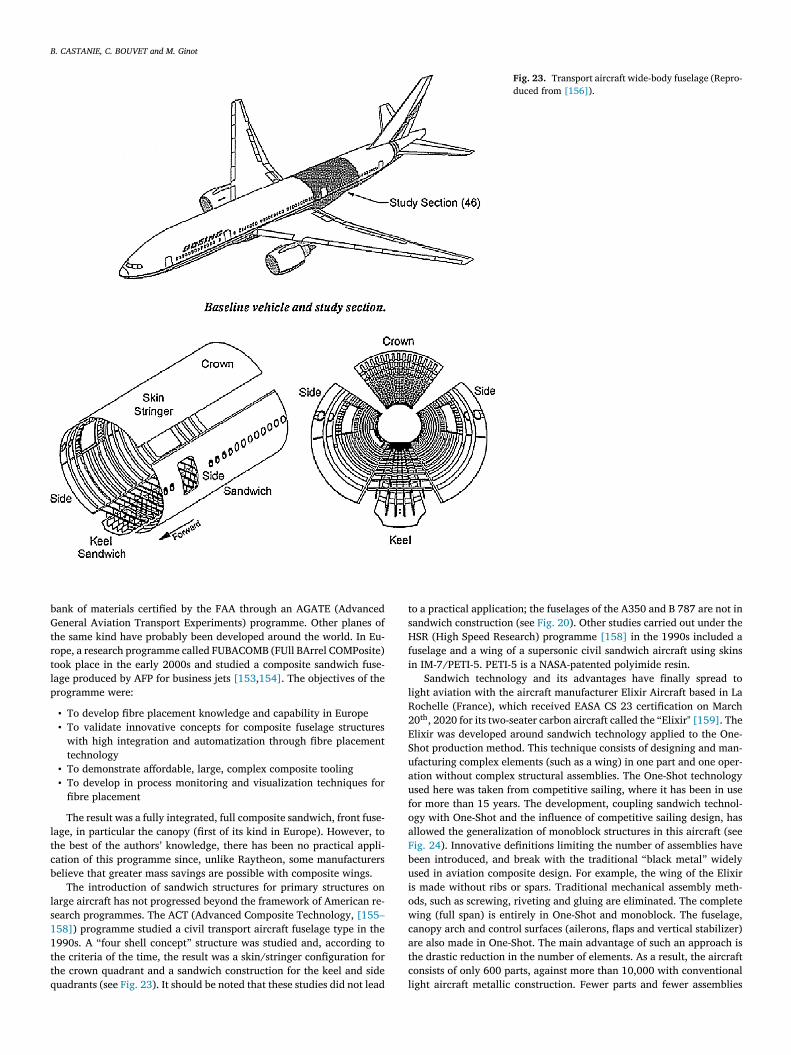
Fig. 23. Transport aircraft wide-body fuselage (Repro- duced from [156] ).
b
G
t
r
t
l
p
l
t
c
b
l
s1
1
t
t
q
t
s
H
f
i
l
R
2
E
S
u
a
u
f
o
a
F
b
u
i
o
w
c
a
t
c
l
ank of materials certified by the FAA through an AGATE (Advancedeneral Aviation Transport Experiments) programme. Other planes of
he same kind have probably been developed around the world. In Eu-ope, a research programme called FUBACOMB (FUll BArrel COMPosite)ook place in the early 2000s and studied a composite sandwich fuse-age produced by AFP for business jets [153 , 154] . The objectives of therogramme were:
• To develop fibre placement knowledge and capability in Europe • To validate innovative concepts for composite fuselage structures
with high integration and automatization through fibre placementtechnology
• To demonstrate affordable, large, complex composite tooling • To develop in process monitoring and visualization techniques for
fibre placement
The result was a fully integrated, full composite sandwich, front fuse-age, in particular the canopy (first of its kind in Europe). However, tohe best of the authors’ knowledge, there has been no practical appli-ation of this programme since, unlike Raytheon, some manufacturerselieve that greater mass savings are possible with composite wings.
The introduction of sandwich structures for primary structures onarge aircraft has not progressed beyond the framework of American re-earch programmes. The ACT (Advanced Composite Technology, [155–58] ) programme studied a civil transport aircraft fuselage type in the990s. A “four shell concept ” structure was studied and, according tohe criteria of the time, the result was a skin/stringer configuration forhe crown quadrant and a sandwich construction for the keel and sideuadrants (see Fig. 23 ). It should be noted that these studies did not lead
o a practical application; the fuselages of the A350 and B 787 are not inandwich construction (see Fig. 20 ). Other studies carried out under theSR (High Speed Research) programme [158] in the 1990s included a
uselage and a wing of a supersonic civil sandwich aircraft using skinsn IM-7/PETI-5. PETI-5 is a NASA-patented polyimide resin.
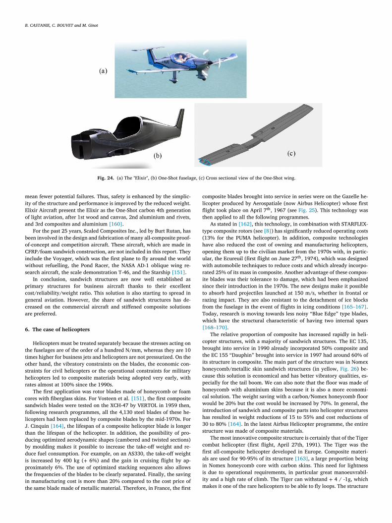
Sandwich technology and its advantages have finally spread toight aviation with the aircraft manufacturer Elixir Aircraft based in Laochelle (France), which received EASA CS 23 certification on March0 th , 2020 for its two-seater carbon aircraft called the “Elixir" [159] . Thelixir was developed around sandwich technology applied to the One-hot production method. This technique consists of designing and man-facturing complex elements (such as a wing) in one part and one oper-tion without complex structural assemblies. The One-Shot technologysed here was taken from competitive sailing, where it has been in useor more than 15 years. The development, coupling sandwich technol-gy with One-Shot and the influence of competitive sailing design, hasllowed the generalization of monoblock structures in this aircraft (seeig. 24 ). Innovative definitions limiting the number of assemblies haveeen introduced, and break with the traditional “black metal ” widelysed in aviation composite design. For example, the wing of the Elixirs made without ribs or spars. Traditional mechanical assembly meth-ds, such as screwing, riveting and gluing are eliminated. The completeing (full span) is entirely in One-Shot and monoblock. The fuselage,
anopy arch and control surfaces (ailerons, flaps and vertical stabilizer)re also made in One-Shot. The main advantage of such an approach ishe drastic reduction in the number of elements. As a result, the aircraftonsists of only 600 parts, against more than 10,000 with conventionalight aircraft metallic construction. Fewer parts and fewer assemblies
B. CASTANIE, C. BOUVET and M. Ginot
Fig. 24. (a) The "Elixir", (b) One-Shot fuselage, (c) Cross sectional view of the One-Shot wing.
m
i
E
o
a
b
o
C
i
w
s
p
c
g
c
a
6
t
t
o
s
h
r
c
s
f
l
J
t
d
b
d
i
p
t
i
t
c
l
fl
t
t
(
h
o
u
w
r
i
s
t
r
f
T
w
[
c
b
t
i
h
c
p
h
c
w
i
h
3
s
c
fi
a
i
i
i
m
ean fewer potential failures. Thus, safety is enhanced by the simplic-ty of the structure and performance is improved by the reduced weight.lixir Aircraft present the Elixir as the One-Shot carbon 4th generationf light aviation, after 1st wood and canvas, 2nd aluminium and rivets,nd 3rd composites and aluminium [160] .
For the past 25 years, Scaled Composites Inc., led by Burt Rutan, haseen involved in the design and fabrication of many all-composite proof-f-concept and competition aircraft. These aircraft, which are made inFRP/foam sandwich construction, are not included in this report. They
nclude the Voyager, which was the first plane to fly around the worldithout refuelling, the Pond Racer, the NASA AD-1 oblique wing re-
earch aircraft, the scale demonstration T-46, and the Starship [151] . In conclusion, sandwich structures are now well established as
rimary structures for business aircraft thanks to their excellentost/reliability/weight ratio. This solution is also starting to spread ineneral aviation. However, the share of sandwich structures has de-reased on the commercial aircraft and stiffened composite solutionsre preferred.
. The case of helicopters
Helicopters must be treated separately because the stresses acting onhe fuselages are of the order of a hundred N/mm, whereas they are 10imes higher for business jets and helicopters are not pressurized. On thether hand, the vibratory constraints on the blades, the economic con-traints for civil helicopters or the operational constraints for militaryelicopters led to composite materials being adopted very early, withates almost at 100% since the 1990s.
The first application was rotor blades made of honeycomb or foamores with fiberglass skins. For Vosteen et al. [151] , the first compositeandwich blades were tested on the XCH-47 by VERTOL in 1959 then,ollowing research programmes, all the 4,130 steel blades of these he-icopters had been replaced by composite blades by the mid-1970s. For. Cinquin [164] , the lifespan of a composite helicopter blade is longerhan the lifespan of the helicopter. In addition, the possibility of pro-ucing optimized aerodynamic shapes (cambered and twisted sections)y moulding makes it possible to increase the take-off weight and re-uce fuel consumption. For example, on an AS330, the take-off weights increased by 400 kg ( + 6%) and the gain in cruising flight by ap-roximately 6%. The use of optimized stacking sequences also allowshe frequencies of the blades to be clearly separated. Finally, the savingn manufacturing cost is more than 20% compared to the cost price ofhe same blade made of metallic material. Therefore, in France, the first
omposite blades brought into service in series were on the Gazelle he-icopter produced by Aerospatiale (now Airbus Helicopter) whose firstight took place on April 7 th , 1967 (see Fig. 25 ). This technology washen applied to all the following programmes.
As stated in [162] , this technology, in combination with STARFLEX-ype composite rotors (see [8] ) has significantly reduced operating costs13% for the PUMA helicopter). In addition, composite technologiesave also reduced the cost of owning and manufacturing helicopters,pening them up to the civilian market from the 1970s with, in partic-lar, the Ecureuil (first flight on June 27 th , 1974), which was designedith automobile techniques to reduce costs and which already incorpo-
ated 25% of its mass in composite. Another advantage of these compos-te blades was their tolerance to damage, which had been emphasizedince their introduction in the 1970s. The new designs make it possibleo absorb hard projectiles launched at 150 m/s, whether in frontal orazing impact. They are also resistant to the detachment of ice blocksrom the fuselage in the event of flights in icing conditions [165–167] .oday, research is moving towards less noisy “Blue Edge ” type blades,hich have the structural characteristic of having two internal spars
168–170] . The relative proportion of composite has increased rapidly in heli-
opter structures, with a majority of sandwich structures. The EC 135,rought into service in 1990 already incorporated 50% composite andhe EC 155 “Dauphin ” brought into service in 1997 had around 60% ofts structure in composite. The main part of the structure was in Nomexoneycomb/metallic skin sandwich structures (in yellow, Fig. 26 ) be-ause this solution is economical and has better vibratory qualities, es-ecially for the tail boom. We can also note that the floor was made ofoneycomb with aluminium skins because it is also a more economi-al solution. The weight saving with a carbon/Nomex honeycomb floorould be 20% but the cost would be increased by 70%. In general, the
ntroduction of sandwich and composite parts into helicopter structuresas resulted in weight reductions of 15 to 55% and cost reductions of0 to 80% [164] . In the latest Airbus Helicopter programme, the entiretructure was made of composite materials.
The most innovative composite structure is certainly that of the Tigerombat helicopter (first flight, April 27th, 1991). The Tiger was therst all-composite helicopter developed in Europe. Composite materi-ls are used for 90-95% of its structure [163] , a large proportion beingn Nomex honeycomb core with carbon skins. This need for lightnesss due to operational requirements, in particular great manoeuvrabil-ty and a high rate of climb. The Tiger can withstand + 4 / -1g, whichakes it one of the rare helicopters to be able to fly loops. The structure

B. CASTANIE, C. BOUVET and M. Ginot
Fig. 25. Left: photo of historical blades (the smaller: Gazelle helicopter, the larger: Puma helicopter), from [161,162] ; Right: typical section of a blade manufactured at Institut Clément Ader with a front spar used for impact research [158–160] .
Fig. 26. Structure of the EC 155 "Dauphin", reproduced from
[163] .
w
b
a
t
p
v
s
t
t
c
8
t
h
7
t
g
v
o
w
d
C
t
h
n
a
I
t
b
o
w
C
v
a
t
eight /maximum take-off weight ratio is exceptional even if it cannote given here. The AH-64 Apache helicopter is a reference in this fieldnd the Tiger weighs 40% less [171] .
Despite this extreme lightness, the Tiger was certified with fatigueests on a new structure that had deliberately been given damage (im-acts and manufacturing defects) corresponding to several times the ser-ice life, then a static test at extreme load was conducted on the sametructure and finally a crash test was performed, again on the same struc-ure. In the event of a crash, the helicopter must ensure the survival ofhe crew, which it has done in operational conditions several times. Therash calculation on composite structures was extremely new in the late0s and early 90s, yet the challenge was taken up by engineers of theime. Tiger technologies have also been applied to the NH 90 transportelicopter, which has a slightly lower rate of composites [163] .
. Future of aeronautic sandwich structures
Research is mainly focused on structural improvement, the integra-ion of functions and the multifunctionality of sandwich structures. Re-
arding structural improvement, many innovative cores have been de-eloped or rediscovered in recent years. A brief, non-exhaustive reviewf many sandwich cores can be found in [8] : foams, balsa, cork, ply-ood, honeycomb, and other shapes, lattice cores (Kagome, tetrahe-ral, pyramidal or other), corrugated, folded, X-Cor, Hierarchical, Napore, Entangled carbon fibres among probable others. Only a few ofhese possibilities could be interesting to replace Nomex or aluminiumoneycombs, which are very efficient. Ullah et al. [172] studied a tita-ium kagome core that outperformed traditional honeycombs in shearnd compression. This solution is proposed for ailerons (see Fig. 27 ).t also has the advantage of being ventilated, which eliminates the po-ential problems of moisture ingression. A review of the different possi-ilities of this type of core, in particular from the multifunctional pointf view, was made by Han et al. [176] . Folded cores have also beenidely studied in recent years, especially in the VeSCo (Ventable Shearore, [145 , 173] ) programme. They have the major advantage of beingentilated but they can also be optimized to improve the manufacturingnd the skin/core bonding strength [174] , see Fig. 27 . These origami-ype structures offer a wide variety of materials and possible patterns
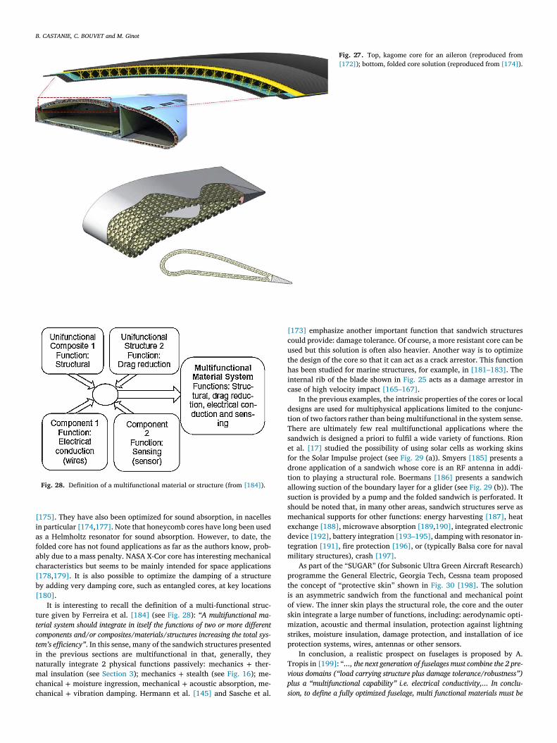
B. CASTANIE, C. BOUVET and M. Ginot
Fig. 27. Top, kagome core for an aileron (reproduced from
[172] ); bottom, folded core solution (reproduced from [174] ).
Fig. 28. Definition of a multifunctional material or structure (from [184] ).
[
i
a
f
a
c
[
b
[
t
t
c
t
i
n
m
c
c
[
c
u
t
h
i
c
d
t
T
s
e
f
d
t
a
s
s
m
e
d
t
m
p
t
i
o
s
m
s
p
T
v
p
s
175] . They have also been optimized for sound absorption, in nacellesn particular [174 , 177] . Note that honeycomb cores have long been useds a Helmholtz resonator for sound absorption. However, to date, theolded core has not found applications as far as the authors know, prob-bly due to a mass penalty. NASA X-Cor core has interesting mechanicalharacteristics but seems to be mainly intended for space applications178 , 179] . It is also possible to optimize the damping of a structurey adding very damping core, such as entangled cores, at key locations180] .
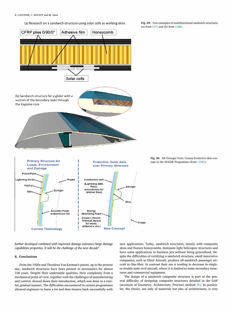
It is interesting to recall the definition of a multi-functional struc-ure given by Ferreira et al. [184] (see Fig. 28 ): “A multifunctional ma-
erial system should integrate in itself the functions of two or more different
omponents and/or composites/materials/structures increasing the total sys-
em’s efficiency ”. In this sense, many of the sandwich structures presentedn the previous sections are multifunctional in that, generally, theyaturally integrate 2 physical functions passively: mechanics + ther-al insulation (see Section 3 ); mechanics + stealth (see Fig. 16 ); me-
hanical + moisture ingression, mechanical + acoustic absorption, me-hanical + vibration damping. Hermann et al. [145] and Sasche et al.
173] emphasize another important function that sandwich structuresould provide: damage tolerance. Of course, a more resistant core can besed but this solution is often also heavier. Another way is to optimizehe design of the core so that it can act as a crack arrestor. This functionas been studied for marine structures, for example, in [181–183] . Thenternal rib of the blade shown in Fig. 25 acts as a damage arrestor inase of high velocity impact [165–167] .
In the previous examples, the intrinsic properties of the cores or localesigns are used for multiphysical applications limited to the conjunc-ion of two factors rather than being multifunctional in the system sense.here are ultimately few real multifunctional applications where theandwich is designed a priori to fulfil a wide variety of functions. Riont al. [17] studied the possibility of using solar cells as working skinsor the Solar Impulse project (see Fig. 29 (a)). Smyers [185] presents arone application of a sandwich whose core is an RF antenna in addi-ion to playing a structural role. Boermans [186] presents a sandwichllowing suction of the boundary layer for a glider (see Fig. 29 (b)). Theuction is provided by a pump and the folded sandwich is perforated. Ithould be noted that, in many other areas, sandwich structures serve asechanical supports for other functions: energy harvesting [187] , heat
xchange [188] , microwave absorption [189 , 190] , integrated electronicevice [192] , battery integration [193–195] , damping with resonator in-egration [191] , fire protection [196] , or (typically Balsa core for navalilitary structures), crash [197] .
As part of the “SUGAR ” (for Subsonic Ultra Green Aircraft Research)rogramme the General Electric, Georgia Tech, Cessna team proposedhe concept of “protective skin ” shown in Fig. 30 [198] . The solutions an asymmetric sandwich from the functional and mechanical pointf view. The inner skin plays the structural role, the core and the outerkin integrate a large number of functions, including: aerodynamic opti-ization, acoustic and thermal insulation, protection against lightning
trikes, moisture insulation, damage protection, and installation of icerotection systems, wires, antennas or other sensors.
In conclusion, a realistic prospect on fuselages is proposed by A.ropis in [199] : “..., the next generation of fuselages must combine the 2 pre-
ious domains ( “load carrying structure plus damage tolerance/robustness ”)
lus a “multifunctional capability ” i.e. electrical conductivity,... In conclu-
ion, to define a fully optimized fuselage, multi functional materials must be
B. CASTANIE, C. BOUVET and M. Ginot
Fig. 29. Two examples of multifunctional sandwich structures (a) from [17] and (b) from [186] .
Fig. 30. GE/Georgia Tech/ Cessna Protective skin con- cept in the SUGAR Programme (from [198] ).
f
c
8
d
1
m
a
f
a
n
s
h
s
c
c
o
t
e
(
l
urther developed combined with improved damage tolerance/large damage
apabilities properties. It will be the challenge of the next decade ”.
. Conclusions
From the 1920s and Theodore Von Karman’s patent, up to the presentay, sandwich structures have been present in aeronautics for almost00 years. Despite their undeniable qualities, their complexity from aechanical point of view, together with the challenges of manufacturing
nd control, slowed down their introduction, which was done in a care-ul, gradual manner. The difficulties encountered in certain programmesllowed engineers to learn a lot and then bounce back successfully with
ew applications. Today, sandwich structures, mainly with compositekins and Nomex honeycombs, dominate light helicopter structures andave some applications in business jets without being generalized. De-pite the difficulties of certifying a sandwich structure, small innovativeompanies, such as Elixir Aircraft, produce all-sandwich passenger air-raft in One-Shot. In contrast their use is tending to decrease in single-r double-aisle civil aircraft, where it is limited to some secondary struc-ures and commercial equipment.
The design of a sandwich composite structure is part of the gen-ral difficulty of designing composite structures detailed in the GAPacronym of Geometry, Architecture, Process) method [8] . In particu-ar, the choice, not only of materials but also of architectures, is very

B. CASTANIE, C. BOUVET and M. Ginot
v
p
t
i
s
i
t
o
e
t
D
i
t
A
n
s
t
c
h
t
C
p
(
b
L
U
A
R
ast and no real methodology has been established. However, this “hy-erchoice of materials and architectures ” can prove to be an advan-age in the integration of functions, which will be the future of compos-te aeronautical structures. Beyond multi-physical solutions, sandwichtructures could enable a real integration of systems to be achieved, ass beginning to be analysed in the space domain [200] and proposed inhe SUGAR programme. This will require adaptation of the industrialrganization. The launch of new research programmes can provide andxperience this new paradigm and encourage learning and dialogue be-ween specialists in systems and structures.
eclaration of Competing Interest
The authors declare that they have no known competing financialnterests or personal relationships that could have appeared to influencehe work reported in this paper.
cknowledgements
This paper is a result of 25 years of experience in the field of aero-autic composite structures at the Institut Clement Ader, Toulouse, andtrong relationships with the Aircraft Industry. The first author wisheso thank more specially his former advisors during his PhD with Euro-opter: Jean-Pierre Jaouen (Now retired) and Alain Crouzet (now Da-er). The authors also thank their PhD students who have contributedo the knowledge of sandwich structures: Jaime Rivera (Fuerza Aera dehile), Yulfian Aminanda (now Universiti Teknologi Brunei), Phachara-orn Bunyawanichakul (Kasetsart University, Thailand), Laurent MezeixBurapha University, Thailand), John Susaisnathan (University of Ne-rija, Spain) and Juan de Dios Rodriguez Ramirez. Special thanks to J.eibacher (Webmaster of Soaring Magazine archive and professor at theniversity of Tucson) and Nicolas Mahuet (Head of engineering of Elixirircraft) for their help.
eferences
[1] N.J. Hoff, S.E. Mautner , Sandwich construction, Aeronaut. Eng. Rev. 3 (1944) 1–7 .[2] H.G. Allen, Analysis and Design of Structural Sandwich Panels. Pergamon Press,
Oxford 1969 [3] F.G. Plantema , Sandwich Construction, John Wiley & Sons, New-York, 1966 . [4] D. Zenkerts, The Handbook of Sanwdich Construction. E-MAS Publishing, London
1997 [5] C. Kassapoglou , Design and Analysis of Composite Structures (with application to
aerospace structures), Wiley, Chichester UK, 2010 . [6] L.A. Carlsson , G.A. Kardomateas , Structural and Failure Mechanics of Sandwich
Composites, Springer, Dordrecht NL, 2011 . [7] D. Gay , Composite Materials Design and Applications, CRC press, Boca Raton FL,
2015 . [8] F. Neveu, B. Castanié, P. Olivier, The GAP methodology: A new
way to design composite structure Mater. Des. 172, 107755,doi: https://doi.org/10.1016/j.matdes.2019.107755 .
[9] D. Guedra-Degeorges , P. Thevenet , S. Maison , Damage Tolerance of Aeronauti-cal Sandwich Structures, in: A. Vautrin (Ed.), Mechanics of Sandwich Structures,Kluwer Academic Publisher, 1998, pp. 29–36 .
[10] J. Tomblin, T. Lacy, B. Smith, S. Hooper, A. Vizzini, S. Lee, Review of damagetolerance for composite sandwich airframe structures, FAA Report DOT/FAA/AR-99/49, 1999.
[11] B. Castanié, J.-J. Barrau, J.-P. Jaouen, Theoretical and experimental anal-ysis of asymmetric sandwich structures, Comp. Struct. 55 (2002) 295–306,doi: 10.1016/S0263-8223(01)00156-8 .
[12] B. Castanié, J.-J. Barrau, J.-P. Jaouen, S. Rivallant, Combined shear/compressionstructural testing of asymmetric sandwich structures, Exp. Mech 44 (2004) 461–472, doi: 10.1007/BF02427957 .
[13] B. Castanié, Contribution à l’étude des structures sandwichs dissymétriques, PhDSupaéro 2000. http://oatao.univ-toulouse.fr/4282/ .
[14] J. Zhang, Q. Qin, X. Han, W. Ai, The initial plastic failure of fully clamped geo-metrical asymmetric metal foam core sandwich beams, Comp. Part B 87 (2016)233–244, doi: 10.1016/j.compositesb.2015.10.027 .
[15] J. Deng, A. Peng, W. Chen, G. Zhou, X. Wang, On stability and damage behaviorof asymmetric sandwich panels under uniaxial compression, J. Sandwich Struct.Mater. On line (Feb 2020), doi: 10.1177/1099636220905778 .
[16] A. Fink, C. Einzmann, Discrete tailored asymmetric sandwich structures, Comp.Struct. 238 (2020) 111990, doi: 10.1016/j.compstruct.2020.111990 .
[17] J. Rion, Y. Leterrier, J.-A.E. Månson, J.-M. Blairon, Ultra-light asymmet-ric photovoltaic sandwich structures, Comp. Part A 40 (2009) 1167–1173,doi: 10.1016/j.compositesa.2009.05.015 .
[18] K.E. Evans, The design of doubly curved sandwich panels with honeycomb core,Comp. Struct. 17 (1991) 95–111, doi: 10.1016/0263-8223(91)90064-6 .
[19] S. Smidt, Bending of curved sandwich beams, a numerical approach, Comp. Struct.34 (1996) 279–290, doi: 10.1016/0263-8223(95)00149-2 .
[20] O.T. Thomsen, J.R. Vinson, Conceptual design principles for non-circularpressurized sandwich fuselage sections – a design study based on a high-order sandwich theory formula-tion, J. Comp. Mater. 36 (2002) 313–345,doi: 10.1177/0021998302036003468 .
[21] N.J. Hoff, S.E. Mautner, The buckling of sandwich type model, J. Aeronaut. Sci. 12(July 1945), doi: 10.2514/8.11246 .
[22] L. Fagerberg, D. Zenkert, Imperfection-induced wrinkling material fail-ure in sandwich panels, J. Sand. Struct. Mat. 7 (2005) 195–219,doi: 10.1177/1099636205048526 .
[23] E.E. Gdoutos, I.M. Daniel, K.A. Wang, Compression facing wrinklingof composite sandwich structures, Mech. Mater. 35 (2003) 511–522,doi: 10.1016/S0167-6636(02)00267-3 .
[24] L. Fagerberg, D. Zenkert, Effects of Anisotropy and Multi-axial Loading onthe Wrinkling of Sandwich Panels, J. Sand. Struct. Mater. 7 (2005) 177–194,doi: 10.1177/109963205048525 .
[25] B.K. Hadi, F.L. Matthews, Development of Benson-Mayers theory on the wrin-kling of anisotropic sandwich panels, Comp. Struct. 49 (2000) 425–434,doi: 10.1016/S0263-8223(00)00077-5 .
[26] R. Vescovini, M. D’Ottavio, L. Dozio, O. Polit, Buckling and wrinkling ofanisotropic sandwich plates International, J.Eng. Sci. 130 (2018) 136–156,doi: 10.1016/j.ijengsci.2018.05.010 .
[27] K. Niu, R. Talreja, Modeling of wrinkling in sandwich pan-els under compression, J. Eng. Mech. 125 (1999) 875–883,doi: 10.1061/(ASCE)0733-9399(1999)125:8(875) .
[28] K. Yu, H. Hu, S. Chen, S. Belouettar, M. Potier-Ferry, Multi-scale techniques toanalyze instabilities in sandwich structures, Comp. Struct. 96 (2013) 751–762,doi: 10.1016/j.compstruct.2012.10.007 .
[29] M.A. Douville, P. Le Grognec, Exact analytical solutions for the local and globalbuckling of sandwich beam-columns under various loadings, Int. J. Sol. Struct. 50(2013) 2597–2609, doi: 10.1016/j.ijsolstr.2013.04.013 .
[30] L. Léotoing, S. Drapier, A. Vautrin, Nonlinear interaction of geometrical and mate-rial properties in sandwich beam instabilities, Int. J. Sol. Struct. 39 (2002) 3717–3739, doi: 10.1016/S0020-7683(02)00181-6 .
[31] J. Bertolini, B. Castanié, J.J. Barrau, J.P. Navarro, C. Petiot, Multi-levelexperimental and numerical analysis of composite stiffener debonding.Part 2: Element and panel level, Comp. Struct. 90 (2009) 392–403,doi: 10.1016/j.compstruct.2009.04.002 .
[32] S. Zhang, J.M. Dulieu-Barton, O.T. Thomsen, The effect of temperature on the fail-ure modes of polymer foam cored sandwich structures, Comp. Struct. 121 (2015)104–113, doi: 10.1016/j.compstruct.2014.10.032 .
[33] B. Castanié, J-F. Ferrero , Nonlinear response of symmetric sandwich structures sub-jected to in-plane loads, in: Proceedings of the 10th International Conference onSandwich Structures ICSS, Nantes, France, 2012, pp. 27–29. August 2012 .
[34] B. Castanié, J.-J. Barrau , J.-F. Ferrero , J.-P. Jaouen , Analyse non linéaire et struc-turale des poutres sandwichs dissymétriques, Revue des Composites et des Materi-aux Avances 10 (2000) .
[35] P. Minguet, J. Dugundji, P.A Lagace, Bucking and failure of sandwich plateswith graphite-Epoxy face and various core, in: Proceedings of the 28thAIAA/ASME/ASCE/AHS Structures, Structural Dynamics and Materials Confer-ence, 6-8 April 1987 Paper AIAA-87-07, doi: 10.2514/3.45573 .
[36] A. Tropis , M. Thomas , J.L. Bounie , P. Lafon , Certification of the composite outerwing of the ATR72, J. Aerospace Eng. Proc. Inst. Mech. Eng. Part G 209 (1994)327–339 10.1243/PIME_PROC_1995_209_307_02 .
[37] J. Rouchon , Certification of Large Aircraft Composite Structures, in: Proceedings ofthe 17th ICAS, Recent Progress and New Trends in Compliance Philosophy, Stock-holm, Sweden, 1990 .
[38] E. Morteau, C. Fualdes. Composites @ Airbus, damage tolerance methodology. FAAWork-shop for Composite Damage Tolerance and Maintenance, Chicago IL, 2006.https://www.niar.wichita.edu/niarworkshops/Portals/0/Airbus%20Composites %20-%20Damage%20Tolerance%20Methodolgy%20-%20Fualdes.pdf?ver = 2007- 05-31-095449-530 Accessed 05/26/2020
[39] J.B. Chang, V.K. Goyal, J.C. Klug, J.I. Rome, Composite Structures Damage Toler-ance Analysis Methodologies. NASA/CR-2012-217347
[40] T.D. McQuigg. Compression After Impact Experiments and Analysis on HoneycombCore Sandwich Panels with Thin Facesheets. NASA/CR–2011-217157.
[41] J.S Tomblin, K.S. Raju, J. Liew, B.L Smith. Impact Damage CharacterizationDamage Tolerance of Composite Sandwich Airframe Structures. FAA ReportDOT/FAA/AR-00/44, 2000.
[42] J.S Tomblin, K.S. Raju, J.F. Acosta, B.L. Smith, N.A. Romine, Impact Damage Char-acterization And Damage Tolerance Of Composite Sandwich Airframe Structures-phase II. FAA Report DOT/FAA/AR-02/80, 2002.
[43] J.S Tomblin, K.S. Raju, G. Arosteguy. Damage Resistance and Tolerance of Com-posite Sand-wich Panels —scaling Effects. FAA Report DOT/FAA/AR-03/75, 2003.
[44] Serge Abrate , Bruno Castanié, DS Yapa , Rajapakse, Dynamic failure of compositeand sandwich structures, Springer, Dordrecht NL, 2012 .
[45] S. Heimbs, Virtual testing of sandwich core structures using dynamicfinite element simulations, Comput Mater Sci 45 (2009) 205–216,doi: 10.1016/j.commatsci.2008.09.017 .
[46] Y. Aminanda, B. Castanié, J.-J. Barrau, P. Thevenet, Experimental analysis andmodeling of the crushing of honeycomb cores, App. Comp. Mat. 12 (2005) 213–217, doi: 10.1007/s10443-005-1125-3 .

B. CASTANIE, C. BOUVET and M. Ginot
[
[
[
[
[
[
[
[47] L. Liu, H. Wang, Z. Guan, Experimental and numerical study on the mechanicalresponse of Nomex honeycomb core under transverse loading, Comp. Struct. 121(2015) 304–314, doi: 10.1016/j.compstruct.2014.11.03 .
[48] B. Castanié, C. Bouvet, Y. Aminanda, J.-J. Barrau, P. Thevenet, Modelling of low en-ergy/low velocity impact on nomex honeycomb sandwich structures with metallicskins, Int. J. Imp. Eng. 35 (2008) 620–634, doi: 10.1016/j.ijimpeng.2007.02.008 .
[49] C. Audibert, A.-S. Andréani, E. Lainé, J.-C. Grandidier, Discrete modelling of low-velocity im-pact on Nomex® honeycomb sandwich structures with CFRP skins,Comp. Struct. 207 (2019) 108–118, doi: 10.1016/j.compstruct.2018.09.047 .
[50] Y. Aminanda, B. Castanié, J.-J. Barrau, P. Thevenet, Experimental and numericalstudy of compression after impact of sandwich structures with metallic skins, Comp.Sci. Tech. 69 (2009) 50–59, doi: 10.1016/j.compscitech.2007.10.045 .
[51] T.E. Lacy, Y. Hwang, Numerical modeling of impact-damaged sandwich compositessubjected to compression-after-impact loading, Comp. Struct. 61 (2003) 115–128,doi: 10.1016/S0263-8223(03)00034-5 .
[52] B. Castanié, Y. Aminanda, C. Bouvet, J.-J. Barrau, Core crush criteria to determinethe strength of sandwich composite structures subjected to compression after im-pact, Comp. Struct. 86 (2008) 243–250, doi: 10.1016/j.compstruct.2008.03.032 .
[53] Z. Xie, A.J. Vizzini, A feasible methodology for engineering applications in damagetolerance of composite sandwich structures, J. Comp. Mater 38 (2004) 891–914,doi: 10.1177/2F0021998304042476 .
[54] R. Aitken , Damage due to soft body impact on composite sandwich aircraft panelsPhD Thesis, University of Auckland, Department of Mechanical Engineering, 2000 .
[55] S. Guo, R. Morishima, Numerical analysis and experiment of composite sand-wich T-joints sub-jected to pulling load, Comp. Struct. 94 (2011) 229–238,doi: 10.1016/j.compstruct.2011.06.022 .
[56] P. Sheahen , L. Betsuch , T. Holcombe , B. Baron , Robust composite sandwich struc-tures. AIAA/ASME/ASCE/AHS/ASC Structures, Structural Dynamics and Materi-als Conference, in: Proceedings of the 1998 39th AIAA/ASME/ASCE/AHS/ASCStructures, Structural Dynamics, and Materials Conference and Exhibit andAIAA/ASME/AHS Adaptive Structures Forum. Part 1 (of 4), 3, Long Beach, CA,USA, 1998, pp. 2228–2238. 20 -23 April 1998 .
[57] J. Feldhusen, C. Warkotsch, A. Kempf, Development of a mechanical technol-ogy for joining sandwich elements, J. Sand. Struct. Mat. 11 (2009) 471–486,doi: 10.1177/1099636209105378 .
[58] U.V.R.S. Turaga , C.T. Sun , Failure Modes and Load Transfer in Sandwich T-Joints,J. Sand. Struct. Mater. 2 (2000) 225–245 10.1177/109963620000200304 .
[59] Frank J. Filippi , Boris Levenetz , Optimum Joint Design for High-Temperature Hon-eycomb Panels, SAE Trans. 68 (1960) 658–664 www.jstor.org/stable/44565172JSTORAccessed 19 Apr. 2020 .
[60] S. Heimbs, M. Pein, Failure behaviour of honeycomb sandwich corner joints andinserts, Comp. Struct 89 (2009) 575–588, doi: 10.1016/j.compstruct.2008.11.013 .
[61] B.J. Kim, D.G. Lee, Development of a satellite structure with the sandwich T-joint,Comp. Struct. 92 (2010) 460–468, doi: 10.1016/j.compstruct.2009.08.030 .
[62] E. Bozhevolnaya, A. Lyckegaard, Local effects at core junctions of sandwichstructures under different types of loads, Comp. Struct. 73 (2006) 24–32,doi: 10.1016/j.compstruct.2005.01.031 .
[63] S.S. Vel, V. Caccese, H. Zhao, Elastic coupling effects in tapered sandwich panelswith laminated anisotropic composite facings, J. Comp. Mater. 39 (2005) 2161–2183, doi: 10.1177/0021998305052033 .
[64] O.T. Thomsen, J.R. Vinson, Modeling of tapered sandwich panels using a high-ordersandwich theory formulation, AIAA J 40 (2002) 1867–1875, doi: 10.2514/2.1866 .
[65] S.K. Kuczma, A.J. Vizzini, Failure of sandwich to laminate tapered composite struc-tures, AIAA J 37 (1999) 227–231, doi: 10.2514/2.694 .
[66] C. Gin-Boay, S. Leong-Keey, C. Lee-Soon, Stress distribution in sand-wich beams under tension, Comp. Struct. 45 (1999) 195–204,doi: 10.1016/S0263-8223(99)00026-4 .
[67] J.D. Stromsoe. Modeling of in-plane crushed honeycomb cores with applications torampdown sandwich structure closures. Thesis Faculty of San Diego State Univer-sity 2011
[68] J. Rivera Candia. Theoretical and experimental study of the tapered zone in asym-metrical sandwich structures. PhD Academia Politechnica Aeronautica, Santiagode Chile, November 2003.
[69] ESA PSS-03-1202 Insert Design Handbook, European Space Agency, Noordwijk,The Nether-lands.
[70] MIL-HDBK-23A Structural Sandwich Composites, Departement of Defense USA,1974.
[71] W.G. Youngquist, E.W. Kuenzi, Stresses Included in a Sandwich Panel by Load Ap-plied at an Insert, Forest. Forest Products Laboratory, Report No. 1845, Madison 5,Wisconsin, 1955.
[72] O.T. Thomsen, Sandwich plates with ‘through-the-thickness’ and ‘fully potted’ in-serts: evalua-tion of differences in structural performance, Comp. Struct. 40 (1997)159–174, doi: 10.1016/S0263-8223(98)00017-8 .
[73] J. Wolff, M. Brysch, C. Hühne, Validity check of an analytical dimensioning ap-proach for potted insert load introductions in honeycomb sandwich panels, Comp.Struct. 202 (2018) 1195–1215, doi: 10.1016/j.compstruct.2018.05.105 .
[74] G. Qi, L. Ma, S.-Y. Wang, Modeling and reliability of insert in composite pyra-midal lattice truss core sandwich panels, Comp. Struct. 221 (2019) 110888,doi: 10.1016/j.compstruct.2019.04.060 .
[75] P. Bunyawanichakul, B. Castanie, J.J. Barrau, Experimental and numerical anal-ysis of inserts in sandwich structures, Appl. Comp. Mater. 12 (2005) 177–191,doi: 10.1007/s10443-005-1122-6 .
[76] P. Bunyawanichakul, B. Castanié, J.J. Barrau, Non-linear finite element analysisof inserts in composite sandwich structures, Comp. Part B 39 (2008) 1077–1092,doi: 10.1016/j.compositesb.2008.05.004 .
[77] J.D.D. Rodriguez-Ramirez, B. Castanie, C. Bouvet, Experimental and nu-merical analysis of the shear nonlinear behaviour of Nomex honeycombcore: application to insert sizing, Comp. Struct. 193 (2018) 121–139,doi: 10.1016/j.compstruct.2018.03.076 .
[78] N. Raghu, M. Battley, T. Southward, Strength variability of inserts in sandwich pan-els, J. Sand. Struct. Mater. 11 (2009) 501–517, doi: 10.1177/1099636209104524 .
[79] S. Slimane, S. Kebdani, A. Boudjemai, A. Slimane, Effect of position of tension-loaded inserts on honeycomb panels used for space applications, Int. J. Interact.Des. Manuf. 12 (2018) 393–408, doi: 10.1007/s12008-017-0383-2 .
[80] J.D.D. Rodríguez-Ramírez, B. Castanié, C. Bouvet, On the potting failure of insertsfor sandwich panels: Review of defects and experimental analysis, Mech. Adv. Mat.Struct. On line, doi: 10.1080/15376494.2020.1724352 .
[81] R. Seemann, D. Krause, Numerical modelling of partially potted inserts in honey-comb sand-wich panels under pull-out loading, Comp. Struct. 203 (2018) 101–109,doi: 10.1016/j.compstruct.2018.07.028 .
[82] J.D.D. Rodriguez-Ramirez, B. Castanie, C. Bouvet, Damage mechanics mod-elling of the shear nonlinear behavior of Nomex honeycomb core. Appli-cation to sandwich beams, Mech. Adv. Mater. Struct. 27 (2020) 80–89,doi: 10.1080/15376494.2018.1472351 .
[83] J.D.D. Rodriguez-Ramirez, B. Castanie, C. Bouvet, Insert of sandwich pan-els sizing through a failure mode map, Comp. Struct. 234 (2020) 111724,doi: 10.1016/j.compstruct.2019.111724 .
[84] L. Mezeix, S. Dols, C. Bouvet, B. Castanié, J.P. Giavarini, N. Hongkarn-janakul, Experimental analysis of impact and post-impact behaviour of in-serts in Carbon sandwich structures, J. Sand. Struct. Mat. 21 (2019) 135–153,doi: 10.1177/1099636216687582 .
[85] H.M. Hsiao, S.M. Lee, R.A. Buyny, Core crush problem in manufacturing of com-posite sandwich structures: mechanisms and solutions, AIAA J. 44 (2006) 901–907,doi: 10.2514/1.18067 .
[86] K.F. Karlsson, B.T. Astrom, Manufacturing and applications of struc-tural sandwich components, Comp. Part A 28 (1997) 97–111,doi: 10.1016/S1359-835X(96)00098-X .
[87] D.A. Crump, J.M. Dulieu-Barton, J. Savage, The manufacturing procedure foraerospace secondary sandwich structure panels, J. Sand. Struct. Mat. 12 (2010)421–447, doi: 10.1177/1099636209104531 .
[88] J. Kratz, P. Hubert, Vacuum bag only co-bonding prepreg skins to aramid honey-comb core. Part I. Model and material properties for core pressure during process-ing, Comp. Part A 72 (2015) 228–238, doi: 10.1016/j.compositesa.2014.11.026 .
[89] J. Kratz, P. Hubert, Vacuum-bag-only co-bonding prepreg skins to aramid honey-comb core. Part II. In-situ core pressure response using embedded sensors, Com-posites: Part A 72 (2015) 219–227, doi: 10.1016/j.compositesa.2014.11.030 .
[90] S.S. Tavares, N. Caillet-Bois, V. Michaud, J.A.E. Månson, Non-autoclave processingof honeycomb sandwich structures: Skin through thickness air permeability duringcure, Comp. Part A 41 (2010) 646–652, doi: 10.1016/j.compositesa.2010.01.013 .
[91] S.S. Tavares, V. Michaud, J.A.E. Månson, Assessment of semi-impregnatedfabrics in honeycomb sandwich structures, Comp. Part A 41 (2010) 8–15,doi: 10.1016/j.compositesa.2009.09.005 .
[92] S. Sequeira Tavares, Y. Roulin, V. Michaud, J.A.E. Månson, Hybrid processing ofthick skins for honeycomb sandwich structures, Comp. Sci. Tech. 71 (2011) 183–189, doi: 10.1016/j.compscitech.2010.11.001 .
[93] M. Anders, D. Zebrine, T. Centea, S.R. Nutt, Process diagnostics for co-cure ofsandwich struc-tures using in situ visualization, Comp. Part A 116 (2019) 24–35,doi: 10.1016/j.compositesa.2018.09.029 .
[94] L. Moretti, B. Castanié, G. Bernhart, P Olivier. Characterization and modelling ofcure-dependent properties and strains during composites manufacturing. J. Comp. Mater. On line, doi: 10.1177/0021998320912470 .
[95] L. Mezeix, A. Seman, M.N.M. Nasir, Y. Aminanda, A. Rivai, B. Castanié, P. Olivier,K.M. Ali, Spring-back simulation of unidirectional carbon/epoxy flat laminate com-posite manufactured through autoclave process, Comp. Struct. 124 (2015) 196–205, doi: 10.1016/j.compstruct.2015.01.005 .
[96] M. Fiorina, A. Seman, B. Castanié, K.M. Ali, C. Schwob, L. Mezeix, Spring-in predic-tion for car-bon/epoxy aerospace composite structure, Comp. Struct. 168 (2017)739–745, doi: 10.1016/j.compstruct.2017.02.074 .
[97] G. Fernlund, Spring-in of angled sandwich panels, Comp. Sci.Tech. 65 (2005) 317–323, doi: 10.1016/j.compscitech.2004.08.001 .
[98] E. Kappel, Spring-in of curved CFRP/foam-core sandwich structures, Comp. Struct.128 (2015) 155–164, doi: 10.1016/j.compstruct.2015.03.058 .
[99] E. Kappel, Spring-in of angled sandwich panels, Comp. Sci. Tech. 65 (2005) 317–323, doi: 10.1016/j.compscitech.2004.08.001 .
100] Y. Mahadik, K. Potter, Experimental investigation into the thermoelastic spring-in of curved sandwich panels, Comp. Part A 49 (2013) 68–80,doi: 10.1016/j.compositesa.2013.02.006 .
101] R. Benton Heslehurst , Defects and Damage in Composite Materials and Structures,CRC Press Taylor & Francis Group, Boca Raton, FL USA, 2014 .
102] M.E. Ibrahim, Nondestructive evaluation of thick-section composites and sandwich structures: a review, Comp. Part A 64 (2014) 36–48,doi: 10.1016/j.compositesa.2014.04.010 .
103] J.S. Tomblin, L. Salah, J.M. Welch, M.D. Borgman - Final Report, DOT/FAA/AR-03/74, 2004
104] US Military Handbook 17-3F. Composite materials handbook volume 3. Pol-ymermatrix composites materials usage, design, and analysis. US Departement of De-fense 2002
105] http://www.flight-mechanic.com/composite-honeycomb-sandwich-repairs/ , accessed 22/04/2020
106] C. Duong , C.H. Wang , Composite Repairs, Theory and Design, Elsevier, Amsterdam,2007 .
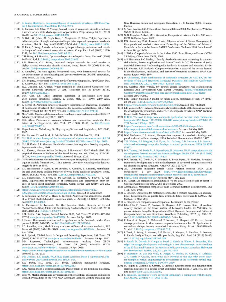
B. CASTANIE, C. BOUVET and M. Ginot
[
[
[
[
[
[
[
[
[
[
[
[
[
[
[[
[
[
[
[
[
[
[
[
[
[
[
[
[
[ /
[
[
[
[
[
[
[
[
[
[
[
[
[
[[
[
[
[[
[
[
[
[[
[
[
[
[
107] R. Benton Heslehurst , Engineered Repairs of Composite Structures, CRC Press Tay-lor & Francis Group, Boca Raton, FL USA, 2019 .
108] K. Katnam, L.D. Silva, T. Young, Bonded repair of composite aircraft structures:a review of scientific challenges and opportunities, Progr Aerosp Sci 61 (2013)26–42, doi: 10.1016/j.paerosci.2013.03.003 .
109] O. Balci, O. Çoban, M. Özgür Bora, E. Akagündüz, E. Bülent Yalçin, Experimen-tal investigation of single and repeated impacts for repaired honeycomb sandwichstructures, Mat. Sci. Eng.: A 682 (2017) 23–30, doi: 10.1016/j.msea.2016.11.030 .
110] H. Park, C. Kong, A study on low velocity impact damage evaluation and re-pairtechnique of small aircraft composite structure, Comp. Part A 42 (2011) 1179–1188, doi: 10.1016/j.compositesa.2011.05.002 .
111] C.H. Wang, A.J. Gunnion, Optimum shapes of scarf repairs, Comp. Part A 40 (2009)1407–1418, doi: 10.1016/j.compositesa.2009.02.009 .
112] A.B. Harman, C.H. Wang, Improved design methods for scarf repairs tohighly strained com-posite aircraft structure, Comp. Struct. 75 (2006) 132–144,doi: 10.1016/j.compstruct.2006.04.091 .
113] F. Campbell, The case against honeycomb core, 49th international society forthe advancement of manufacturing and process engineering (SAMPE) symposium,Long Beach, CA (May 2004).
114] J.H. Fogarty, Honeycomb core and myth of moisture ingression, Appl Comp. Mat.17 (2010) 293–307, doi: 10.1007/s10443-009-9121-7 .
115] W.C. Jackson, T.K. O’Brien, Water Intrusion in Thin-Skinned Composite Hon-eycomb Sandwich Structures, J. Am. Helicopter Soc. 35 (1990) 31–37,doi: 10.4050/JAHS.35.31 .
116] D.M. Cise, R.S. Lakes, Moisture ingression in honeycomb core sand-wich panels: directional aspects, J. Comp. Mat. 31 (1997) 2249–2263,doi: 10.1177/002199839703102202 .
117] E. Kececi, R. Asmatulu, Effects of moisture ingressions on mechanical propertiesof honeycomb-structured fiber composites for aerospace applications, Int. J. Adv.Manuf. Technol. 88 (2017) 459–470, doi: 10.1007/s00170-016-8744-8 .
118] M.E. Tuttle, Moisture diffusion in honeycomb core sandwich composites. ICCM-17Edinburgh, Scotland, July 27-31, 2009.
119] H.G. Allen, Panneaux et volumes obtenus par construction sandwich: Evo-lution et developpe-ment, Mat. Tech. 77 (1989) 11–18, doi: 10.1051/mat-tech/198977060011 .
120] Hugo Junkers, Abdeckung für Flugzeugtragflächen und dergleichen, DE310040,1915
121] Von Karman TH and Stock, P. British Patent No 235 884 June 21, 1924 122] N.J. Hoff, A short history of the development of airplane structures, Am. Sci. 34
(1946) 370–388 www.jstor.org/stable/27826109 JSTORAccessed 22 Apr. 2020 . 123] N.J. Hoff with S.E. Mautner. Sandwich construction in gliders, Soaring magazine,
September-October , 1944 124] A.J. Kinloch, Norman Adrian De Bruyne. 8 November 1904-7 March 1997. Bio-
graphical Memoirs of Fellows of the Royal Society, vol. 46, 2000, pp. 127–143.JSTOR, www.jstor.org/stable/770392 Accessed 19 Apr. 2020.
125] GIFAS (Groupement des industries Aéronautiques Française): L’industrie aéronau-tique et spatiale française 1907-1982, tome I: 1907-1947 Anthologie des deux ou-vrages de 1934 et 1949.
126] J.P. Susainathan, F. Eyma, E. De Luycker, A. Cantarel, B. Castanié, Manufactur-ing and quasi-static bending behavior of wood-based sandwich structures, Comp.Struct. 182 (2017) 487–504, doi: 10.1016/j.compstruct.2017.09.034 .
127] J.P. Susainathan, F. Eyma, E. De Luycker, A. Cantarel, C. Bouvet, B. Cas-tanié, Experimental investigation of compression and compression after im-pact of wood-based sandwich structures, Comp. Struct. 220 (2019) 236–249,doi: 10.1016/j.compstruct.2019.03.095 .
128] https://www.airforce.gov.au/sites/default/files/minisite/static/7522/ RAAFmuseum/exhibitions/restoration/dh_98.htm , accessed 25 April 2020.
129] E. Paroissien, M. Sartor, J. Huet, F. Lachaud, Analytical two-dimensional modelof a hybrid (bolted/bonded) single-lap joint, J. Aircraft 44 (2007) 573–582,doi: 10.2514/1.24452 .
130] E. Paroissien, F. Lachaud, On the Potential Static Strength of Hybrid(Bolted/Bonded) Lap Joints with Functionally Graded Adhesives, AIAA J. 57 (2019)4093–4103, doi: 10.2514/1.J058372 .
131] L.M. Smith, C.W. Rogers, Bonded Bomber B-58, SAE Trans 70 (1962) 477–486JSTOR www.jstor.org/stable/44469505 . Accessed 26 Apr. 2020 .
132] J. Hamer, Honeycomb structure and its application to the Concorde rudder, Com-posites 2 (1971) 242–245, doi: 10.1016/0010-4361(71)90153-4 .
133] J.C. Joanides, et al., Mach 3 wing structures stiffened skin versus sandwich, SAETrans. 69 (1961) 167–178 JSTOR www.jstor.org/stable/44553914 . Accessed 19Apr. 2020 .
134] W.A. Spivak, XB-70A Mach 3 Design and Operating Experience, SAE Trans. 75(1967) 114–126 JSTOR www.jstor.org/stable/44564841 . Accessed 19 Apr. 2020 .
135] D.B. Rogerson, Technological advancements resulting from XB-70performance re-quirements, SAE Trans. 74 (1966) 604–625 JSTORwww.jstor.org/stable/44554241 . Accessed 19 Apr. 2020 .
136] https://www.avionslegendaires.net/avion-militaire/north-american-xb-70-valkyrieaccessed 27/05/2020
137] D.R. Jenkins , T.R. Landis , VALKYRIE, North American Mach 3 superbomber, Spe-ciality Press, 2004 North Branch, MN 55026, USA .
138] R.A. Davis, S.D. Elrod, D.T. Lovell. Titanium honeycomb structure.https://ntrs.nasa.gov/search.jsp?R = 19740022813
139] P.W. Merlin, Mach 3 Legend Design and Development of the Lockheed Blackbird.https://ntrs.nasa.gov/search.jsp?R = 20120013451
140] Peter W. Merlin, Design and development of the blackbird: challenges and lessonslearned. Proceedings of the 47th AIAA Aerospace Sciences Meeting Including The
New Horizons Forum and Aerospace Exposition 5 - 8 January 2009, Orlando,Florida
141] S. Pace. Loockeed SR-71 blackbird. Crowood Edition 2004, Marlborough, WiltshireSN8 2HR, Great Britain.
142] W.G. Roeseler, B. Sarh, M.U. Kismarton. Composite structures: the first 100 years.ICCM 16 Kyoto, Japan 2007.
143] K.B. Armstrong, D.W. Stevens, J. Alet, 25-years of use of Nomex Honeycomb infloor panels and sandwich structures. Proceedings of the 50-Years of AdvancedMaterials or Back to the Future, SAMPE Conference, Toulouse 1994 from June 06to June 10, pp 17-39.
144] J. PORA. Composite Materials in the Airbus A380. From History to Future - ICCM-13 Beijing, China, June 25-29, 2001.
145] A.S. Herrmann, P.C. Zahlen, I. Zuardy. Sandwich structures technology in commer-cial aviation, Present Applications and Future Trends. In O.T. Thomsen et al. (eds),Sandwich Structures 7: Advancing with Sandwich Structures and Materials, 13–26.
146] L.F. Vosteen. R.N. Hadcock. Composite chronicles: a study of the lessons learnedin the development, Production, and Service of composite structures, NASA Con-tractor Report 4620, 1994
147] D. Chaumette , Flight qualification of composite structures At AMD-BA, in: Pro-ceedings of the 23rd Structures, Structural Dynamics and Materials Conference,New Orleans, LA, U.S., 10 May 1982 - 12 May 1982 .
148] Mr. Geoffrey Allen Wardle. My aircraft design, Structures And ManufacturingResearch And Development Core Career Overview. https://fr.slideshare.net/GeoffreyWardleMScMSc/my-full-core-career-presentation-latest-159781260 accessed 28/04/2020.
149] E.H. Hooper, Starship: A model for future design, Materiaux et Tech. 77 (1989)23–30, doi: 10.1051/mattech/198977060023 .
150] https://www.bobscherer.com/Pages/Starship.html Accessed May 4th 2020. 151] L.F. Vosteen, R.N. Hadcock. Composite chronicles: a study of the lessons learned in
the development, production, and service of composite structures. NASA ContractReport 4620. November 1994.
152] K. Retz , The road to large scale composite application on wide body commercialtransports, SAE Trans. 112 (2003) 270–280 www.jstor.org/stable/44699201 JS-TOR Accessed 29 Apr. 2020 .
153] https://www.yumpu.com/en/document/read/38943740/findings-of-the- fubacomp-project-and-links-to-new-developments- Accessed 06 May 2020
154] https://www.azom.com/article.aspx?ArticleID = 2916 Accessed 06 May 2020 155] D.M. McGowan, D.R. Ambur, Compression response of a sandwich fuselage keel
panel with and without damage, NASA Technical Memorandum 110302, 1997. 156] T.H. Walker , P.J. Minguet , B.W. Flynn , D.J. Carbery , G.D. Swanson , L.B. Ilcewicz ,
Advanced technology composite fuselage- structural performance, NASA CR 4732(1997) .
[157] D.R. Tenney , J.G. Davis Jr. , R. Byron Pipes , N. Johnston , NASA composite materialsde-velopment: lessons learned and future challenges, NATO AVT 164 (Fall 2009)(found on NTRS, Accessed 2017-17-12) .
[158] D.R. Tenney, J.G. Davis Jr., N. Johnston, R. Byron Pipes, J.F. McGuire. Structuralframework for flight: nasa’s role in development of advanced composite materialsfor aircraft and space structures. NASA/CR–2011-217076.
[159] JEC Composite magazine article “Elixir Aircraft receives EASA CS-23certification ” 1 apr 2020: http://www.jeccomposites.com/knowledge/international-composites-news/elixir-aircraft-receives-easa-cs-23-certification
[160] https://elixir-aircraft.com/en/ Accessed May 11th, 2020 [161] M. Robert. Les composites aéronautiques: 40 ans déjà et ce n’est que le début !!!
Colloque Composite de TOULOUSE du 3 octobre 2007. 162] Aerospatiale. Materiaux composites: dans la grande mutation des structures. DCT
1135, Avril 1986. 163] J. Cinquin. Utilisation des matériaux composites à matrice organique en aéronau-
tique. Les avantages, les points durs. Vision du futur. Entretiens de l’AMAC. ENSCachan. 19 Mars 2013
164] J. Cinquin. Les composites en aérospatiale. Techniques de l’Ingénieur. 165] Edited by F. Pascal, P. Navarro, S. Marguet, J.-F. Ferrero, Study of medium
velocity impacts on the lower surface of helicopter blades, in: Valentina Lo-presto, Antonio Langella, Serge Abrate (Eds.), Dynamic Response and Failure ofComposite Materials and Structures, Woodhead Publishing, 2017, pp. 159–181,doi: 10.1016/B978-0-08-100887-4.00005-6 . Edited by.
166] F. Pascal, A. Rogani, B. Mahmoud, P. Navarro, S. Marguet, J-F. Ferrero, Impactdamage predic-tion in thin woven composite laminates – Part II: Application tonormal and oblique impacts on sandwich structure, Comp. Struct. 190 (2018) 43–51, doi: 10.1016/j.compstruct.2018.02.013 .
167] I. Tawk, J. Aubry, P. Navarro, J.-F. Ferrero, S. Marguet, S. Rivallant, S. Lemaire,P. Rauch, Study of impact on helicopter blade, Eng. Fail. Anal. 24 (2012) 38–45,doi: 10.1016/j.engfailanal.2012.03.005 .
168] P. Rauch , M. Gervais , P. Cranga , A. Baud , J. Hirsch , A. Walter , P. Beaumier , Blueedge: The design, development and testing of a new blade concept, in: Proceedingsof the 67th Annual Forum of the American Helicopter Society, American HelicopterSoc. International Fairfax, VA, 2011, pp. 542–555 .
169] P. Beaumier , B. Van Der Wall , K. Pengel , C. Kessler , M. Gervais , Y. Delrieux ,J.-F. Hirsch , P. Crozier , From erato basic research to the blue edge rotor blade:an example of virtual engineering? in: Proceedings of the Rotorcraft Virtual Engi-neering Conference, Liverpool, 8-10 Nov. 2016 .
[170] M. Filippi, E. Zappino, E. Carrera, B. Castanié, Effective static and dynamic finiteelement modeling of a double swept composite rotor blade. J. Am. Hel. Soc. Online doi: 10.4050/JAHS.65.032003 .
[171] S. Brosselin , Eurocopter Tiger’s advanced technology: a comparison with the Long-bow Apache, Vertiflite 41 (1995) 18–22 .

B. CASTANIE, C. BOUVET and M. Ginot
[
[
[
[
[
[
[
[
[
[
[
[
[
[
[
[
[
[
172] I. Ullah, J. Elambasseril, M. Brandt, S. Feih, Performance of bio-inspired Kagometruss core structures under compression, Comp. Struct. 118 (2014) 294–302,doi: 10.1016/j.compstruct.2014.07.036 .
173] R. Sachse, D. Fernandez, Y. Klett, P. Middendorf. Integral, disruptive, and mul-tifunctional aircraft structures, in S. Pantelakis, K. Tserpes (eds.), Revolution-izing Aircraft Materials and Processes, Springer Nature Switzerland AG 2020,doi: 10.1007/978-3-030-35346-9_7 .
174] L. Komarnitskiy , L’étude des structures pliables ainsi que la préparation des essaissta-tiques et dynamiques sur celles-ci Master thesis report, Toulouse, UniversityPaul sabatier, 2006 .
175] S. Heimbs, Foldcore, Sandwich structures and their impact performance: anoverview, in: S. Abrate, B. Castanié, Y. Rajapakse (Eds.), Dynamic Failure ofComposite and Sandwich Structures. Solid Mechanics and Its Applications, 192,Springer, Dordrecht, 2013, doi: 10.1007/978-94-007-5329-7_11 .
176] B. Han, Z-J. Zhang, Q-C. Zhang, Q. Zhang, T.J. Lub, B-H. Lua, Recent advancesin hybrid lattice-cored sandwiches for enhanced multifunctional performance, Ext.Mech. Let. 10 (2017) 58–69, doi: 10.1016/j.eml.2016.11.009 .
177] https://cct-kai.com/en/eng-and-services/folded-structures/acoustic-folded-core Accessed 12 May 2020
178] T.K. O’Brien, I.L. Paris, Exploratory investigation of failure mechanisms in transi-tion regions between solid laminates and X-cor truss sandwich, Comp. Struct. 57(2002) 189–204, doi: 10.1016/S0263-8223(02)00083-1 .
179] T.M. Krivanek , B.C. Yount , Composite payload fairing structural architecture as-sessment and selection, SAMPE Conference, May 2012 .
180] A. Shahdin, L. Mezeix, C. Bouvet, J. Morlier, Y. Gourinat, Fabrication and me-chanical testing of glass fiber entangled sandwich beams: a comparison withhoneycomb and foam sandwich beams, Comp. Struct. 90 (2009) 404–412,doi: 10.1016/j.compstruct.2009.04.003 .
181] J.L. Grenestedt, Development of a new peel-stopper for sandwich structures, Comp.Sci. Tech. 61 (2001) 1555–1559, doi: 10.1016/S0266-3538(01)00052-5 .
182] J. Jakobsen, E. Bozhevolnaya, O.T. Thomsen, New peel stopper con-cept for sandwich struc-tures, Comp. Sci. Tech. 67 (2007) 3378–3385,doi: 10.1016/j.compscitech.2007.03.033 .
183] J. Jakobsen, O.T. Thomsen, J.H. Andreasen, E. Bozhevolnaya, Crack deflectionanalyses of different peel stopper design for sandwich structure, Comp. Sci. Tech.69 (2009) 870–875, doi: 10.1016/j.compscitech.2008.01.021 .
184] A.D.B.L. Ferreira, P.R.O. Nóvoa, A. Torres Marques, Multifunctional ma-terial systems: a state-of-the-art review, Comp. Struct. 151 (2016) 3–35,doi: 10.1016/j.compstruct.2016.01.028 .
185] B. Smyers, W. Baron, J. Marshall. Structural-electric characterization of a load bear-ing antenna RF laminate. Proceedings of the COMPTEST 2008 Conference, DaytonOH, October 20-22.
186] L. Boermans , Research on sailplane aerodynamics at delft university of technology.Recent and present developments, in: Proceedings of the Netherlands Associationof Aeronautical Engineers (NVvL), 2006 .
187] Y.-W. Zhang, C. Su, Z.-Y. Ni, J. Zang, L.-Q. Chen, A multifunctional lattice sandwichstructure with energy harvesting and nonlinear vibration control, Comp. Struct.221 (2019) 110875, doi: 10.1016/j.compstruct.2019.04.047 .
188] D.T. Queheillalt, G. Carbajal, G.P. Peterson, H.N.G. Wadley, A multifunctionalheat pipe sandwich panel structure, Int. J. Heat Mass Trans. 51 (2008) 312–326,doi: 10.1016/j.ijheatmasstransfer.2007.03.051 .
189] C. Wang, M. Chen, H. Lei, Z. Zeng, K. Yao, X. Yuan, D. Fang, Frequency-selective-surface based sandwich structure for both effective load bearingand customizable microwave ab-sorption, Comp. Struct. 235 (2020) 111792,doi: 10.1016/j.compstruct.2019.111792 .
[190] P. Bollen , N. Quiévy , C. Bailly , I. Huynen , T. Pardoen , Multifunctional sandwichstructure for electromagnetic absorption and mechanical performances, in: Pro-ceedings of the 16th European Conference on Composite Materials, ECCM, 2014 .
[191] H. Chen, X.P. Li, Y.Y. Chen, G.L. Huang, Wave propagation and absorption of sand-wich beams containing interior dissipative multi-resonators, Ultrasonics 76 (2017)99–108, doi: 10.1016/j.ultras.2016.12.014 .
[192] R. Kothari, C.T. Sun, Design and analysis of multifunctional structures with em-bedded elec-tronics for thermomechanical loads, J. Sand. Struct. Mat. 14 (2012)734–752, doi: 10.1177/1099636212460541 .
[193] Y. Zhang, J. Ma, A.K. Singh, L. Cao, J. Seo, C.D. Rahn, C.E. Bakis, M.A. Hickner,Multi-functional structural lithium-ion battery for electric vehicles, J. Int. Mat. Sys.Struct. 28 (2017) 1603–1613, doi: 10.1177/1045389X16679021 .
[194] L. Zhang, S. Lu, X. Wang, K. Ma, H. Liu, L. Zhou, Manufacture and mechanicalproperties of sandwich structure-battery composites, J. Polym. Eng. 39 (2019) 838–843, doi: 10.1515/polyeng-2019-0143 .
[195] J.P. Thomas, S.M. Qidwai, W.R. Pogue, G.T. Pham, Multifunctional structure-battery com-posites for marine systems, J. Comp. Mat. 47 (2013) 5–26,doi: 10.1177/0021998312460262 .
[196] C. Wang, M. Chen, K. Yao, X. Zhu, D. Fang, Fire protection design for com-posite lattice sandwich structure, Sci.Eng. Comp. Mat. 24 (2017) 919–927,doi: 10.1515/secm-2015-0525 .
[197] A.F. Johnson, Ch.M. Kindervater, K.E. Jackson, Multifunctional design conceptsfor energy absorbing composite fuselage sub-structures, Annual Forum Proceed-ings(1997) - American Helicopter Society, 2, pp. 1115-1128.
[198] M.M. D’Angelo, J. Gallman, V. Johnson, E. Garcia, J. Tai, R. Young. N + 3 SmallCommercial Efficient and Quiet Transportation for Year 2030-2035. NASA/CR–2010-216691
[199] A. Tropis. Composite Structure: Evolution & Future Challenges in Proceedings ofthe Workshop on New Modelling Strategies of Damage and Failure of Compos-ite Structures: A Breakthrough in Composite Sizing? June 30th - July 1st 2014 inToulouse, France.
[200] M. Schubert , S. Perfetto , A. Dafnis , D. Mayer , H. Atzrodt , Development and designof mul-tifunctional lightweight structures for satellite applications, in: Proceedingsof the International Astronautical Congress, IAC, 2018-October .