review of active control and measurements of the...
TRANSCRIPT

Review of Active Control and Measurements of the Response of a
Simple Flame
F.E.C. CULICK and S. PALM
California Institute of Technology
Thank you:
Dr. Saadat Syed (Pratt & Whitney)
William Chen (Caltech)

I. Introduction and Incomplete History
II. The Earliest Results
III. The First Practical Use of Active Control, 1995-2005
IV. Active Control of Large Gas Turbines for Flight
V. Measuring the Combustion Dynamics of a Simple Flame
VI. Concluding Remarks
3
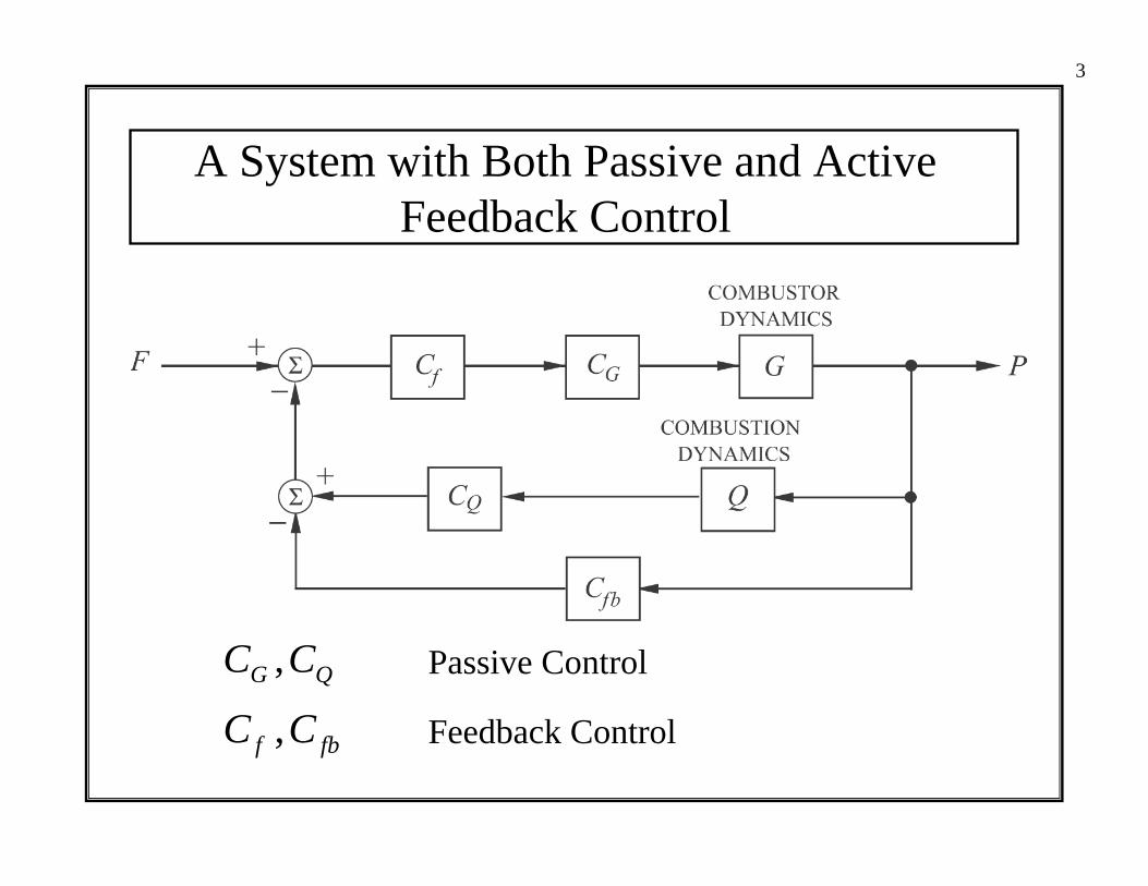
A System with Both Passive and Active Feedback Control
C CG Q, Passive Control
C Cf fb, Feedback Control

4
General Block Diagram
5
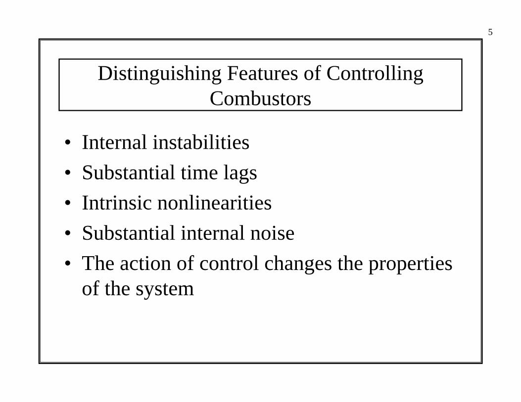
Distinguishing Features of Controlling Combustors
• Internal instabilities• Substantial time lags• Intrinsic nonlinearities• Substantial internal noise• The action of control changes the properties
of the system
6
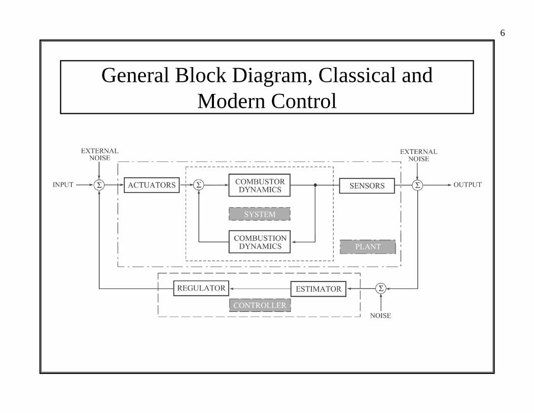
General Block Diagram, Classical and Modern Control

I. Introduction and Incomplete History
II. The Earliest Results
III. The First Practical Use of Active Control, 1995-2005
IV. Active Control of Large Gas Turbines for Flight
V. Measuring the Combustion Dynamics of a Simple Flame
VI. Concluding Remarks

8
The First Proposal for Feedback Control of a Combustor (BOLLAY, 1951; TSIEN, 1952)

9
Tsien’s Analysisd pdt
dpdt
p p t u t2
2 022
' '' ' ( ) ( )+ + = − +α ω β τ
P se G s
e G sU s
s
s( )( )
( )( )=
−
−
−
ββ
τ
τ1
G ss s
( ) =+ +
122
02α ω

10
The First Cambridge Experiments
DINES 1983 HECKL 1985, 1986

11
Cambridge Apparatus Modeling an Afterburner
LANGHORNE 1988
BLOXSIDGE et al. 1988
12
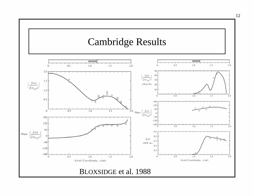
Cambridge Results
BLOXSIDGE et al. 1988

13
Feedback Control at École Centrale
POINSOT et al. 1987, 1988, 1989
(i) No control (ii) With control

14
A General Scheme for Connecting the Physical System, Modeling, Dynamics and Control
15
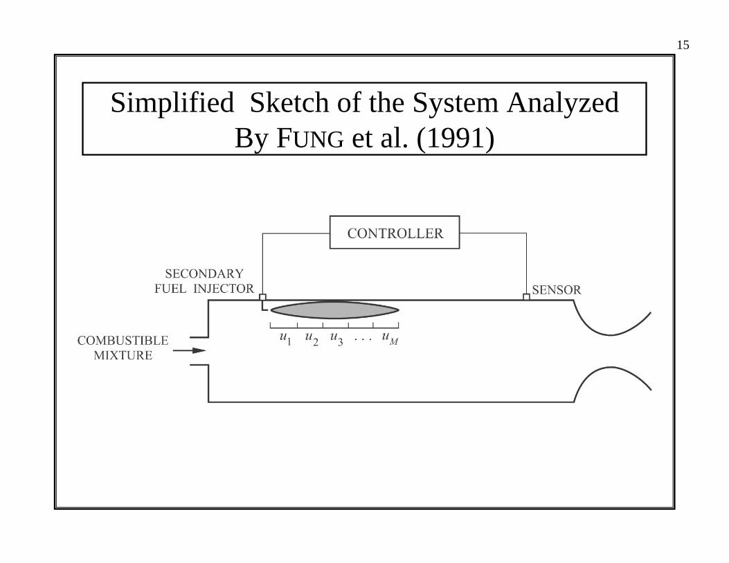
Simplified Sketch of the System Analyzed By FUNG et al. (1991)

I. Introduction and Incomplete History
II. The Earliest Results
III. The First Practical Use of Active Control, 1995-2005
IV. Active Control of Large Gas Turbines for Flight
V. Measuring the Combustion Dynamics of a Simple Flame
VI. Concluding Remarks

17
Feedback Control at Technische UniversitätMünchen (HERMANN et al. 1996)

18
Application of Results by Hermann et al. to the Siemens Machines

19
Doing Away With Active Control of the Siemens Machines (BERENBRINK and HOFFMAN 2000)
I. Introduction and Incomplete History
II. The Earliest Results
III. The First Practical Use of Active Control, 1995-2005
IV. Active Control of Large Gas Turbines for Flight
V. Measuring the Combustion Dynamics of a Simple Flame
VI. Concluding Remarks
21
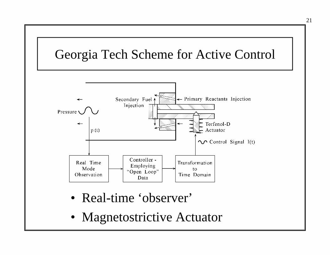
Georgia Tech Scheme for Active Control
• Real-time ‘observer’• Magnetostrictive Actuator

22
GE Dry Low Emissions (DLE) Combustor(LPP, Lean Prevaporized Premixed System)
• Parametric control of instabilities

23
GE DLE ‘Premixer’ with Extended Lean Blowout (ELBO)

24
Pratt & Whitney Talon II Combustor(RQL, Rich Quench Lean System)
• Integral swirlers; swirl introduced with quench stream and cooling air• ‘No’ problems with instabilities• Rich Quench Lean (RQL) combustor

25
Pratt & Whitney Talon II Injector

26
The Trapped Vortex Combustor
• Concept first discussed at AFRL in 1993• Combustion is sustained by a vortex trapped
in a cavity near the injection plane

I. Introduction and Incomplete History
II. The Earliest Results
III. The First Practical Use of Active Control, 1995-2005
IV. Active Control of Large Gas Turbines for Flight
V. Measuring the Combustion Dynamics of a Simple Flame
VI. Concluding Remarks

28
Motivation for Experiments
Combustor Dynamics
Combustion Dynamics
∑External Inputs
q′, Energy Addition
p′Combustor Dynamics
Combustion Dynamics
∑External Inputs
q′, Energy Addition
p′
• The combustion response function is measured by artificially applying an oscillating pressure field and measuring the fluctuating heat release using either chemiluminescence or species specific PLIF.
H sq s qp s p
( )' ( ) /' ( ) /
= s j= ω;
Combustion Response Function
29
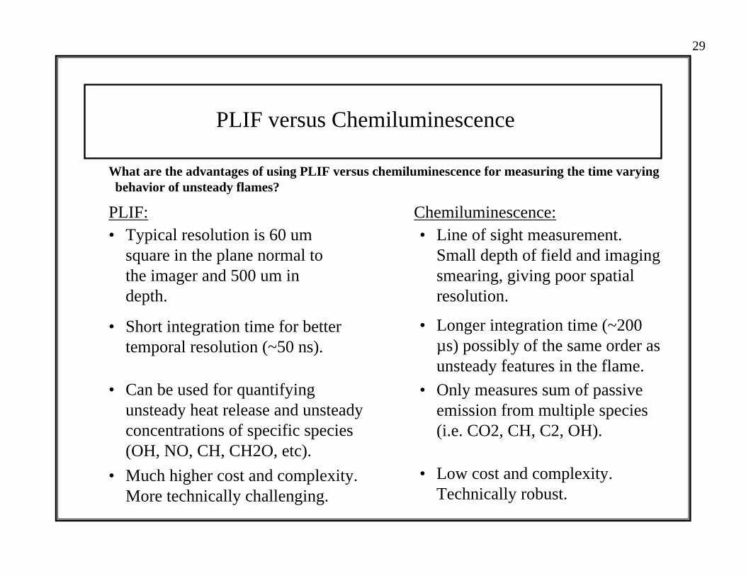
PLIF versus Chemiluminescence
What are the advantages of using PLIF versus chemiluminescence for measuring the time varyingbehavior of unsteady flames?
PLIF: Chemiluminescence:• Typical resolution is 60 um
square in the plane normal to the imager and 500 um in depth.
• Short integration time for better temporal resolution (~50 ns).
• Longer integration time (~200 µs) possibly of the same order as unsteady features in the flame.
• Can be used for quantifying unsteady heat release and unsteady concentrations of specific species (OH, NO, CH, CH2O, etc).
• Only measures sum of passive emission from multiple species (i.e. CO2, CH, C2, OH).
• Much higher cost and complexity. More technically challenging.
• Low cost and complexity. Technically robust.
• Line of sight measurement. Small depth of field and imaging smearing, giving poor spatial resolution.

30
Sheet Generating Cylindrical Optics
OPO
Nd:YAG Laser
ICCD Camera Test Chamber
BandpassFilters
Test Burner
PC Based Data Acquisition System
Experimental Arrangement for PLIF
• Controller uses pressure transducer to keep the p’ amplitude at the flame constant.
• Nd:YAG pumped OPO generates tunable UV light for stimulating emission for select species (PLIF).
• Emission is detected with an ICCD camera.
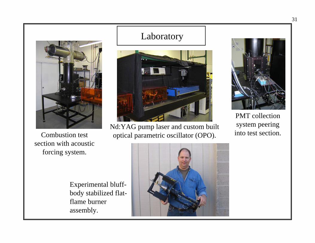
Laboratory
Nd:YAG pump laser and custom builtoptical parametric oscillator (OPO).
Experimental bluff-body stabilized flat-flame burner assembly.
PMT collection system peeringinto test section.Combustion test
section with acoustic forcing system.
31

32
Typical Chemiluminescence ResultsBode Plots for the Combustion Response
• Combustion response function for acoustic forcing of a stagnation plane stabilized flat-flame burner.
• Graphs depict behavior at varying equivalence ratios with flame strain rate held roughly constant.
100.00 1000.00Drive Frequency (Hz)
1.00E-2
1.00E-1
1.00E+0
1.00E+1
1.00E+2
1.00E+3
1.00E+4
Com
bust
ion
Res
pons
e(M
agni
tude
)
Helmholtz response ofthe burner cavity
Equivalence Ratio
0.70
0.75
0.80
0.85
100.00 1000.00Drive Frequency (Hz)
-2160
-1800
-1440
-1080
-720
-360
0
360
Com
bust
ion
Res
pons
e(P
hase
)
Equivalence Ratio
0.70
0.75
0.80
0.85
33
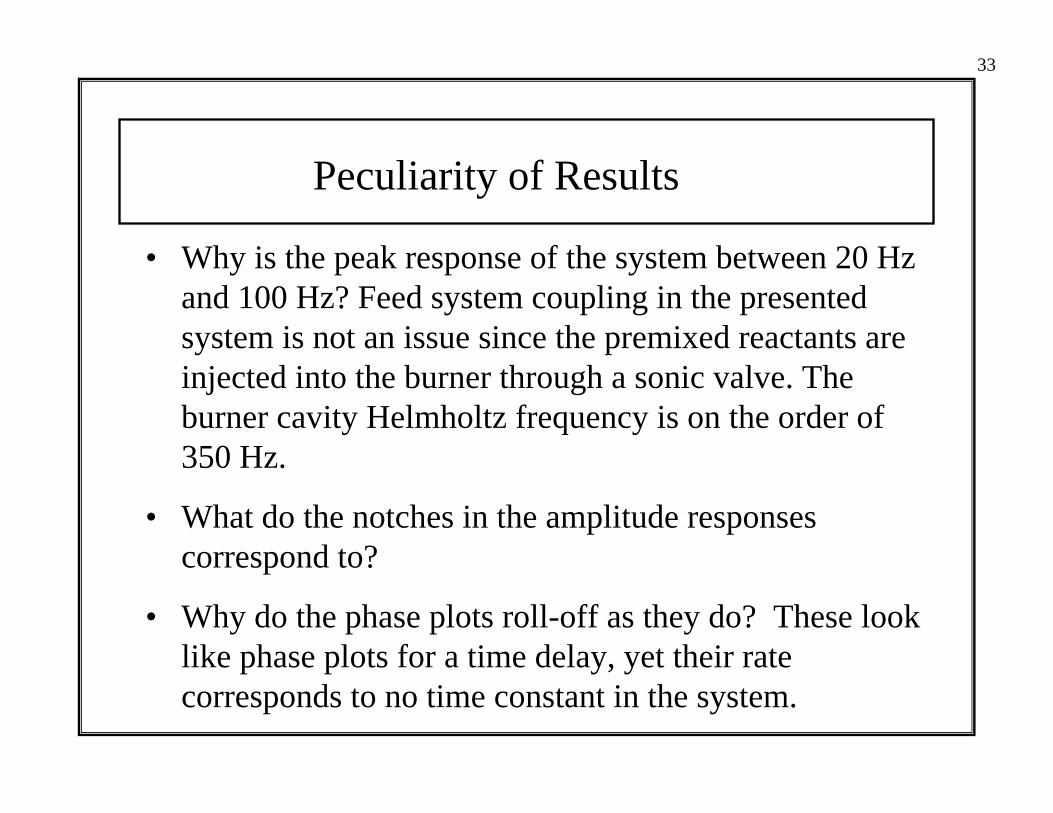
Peculiarity of Results
• Why is the peak response of the system between 20 Hz and 100 Hz? Feed system coupling in the presented system is not an issue since the premixed reactants are injected into the burner through a sonic valve. The burner cavity Helmholtz frequency is on the order of 350 Hz.
• What do the notches in the amplitude responses correspond to?
• Why do the phase plots roll-off as they do? These look like phase plots for a time delay, yet their rate corresponds to no time constant in the system.
I. Introduction and Incomplete History
II. The Earliest Results
III. The First Practical Use of Active Control, 1995-2005
IV. Active Control of Large Gas Turbines for Flight
V. Measuring the Combustion Dynamics of a Simple Flame
VI. Concluding Remarks

35
Concluding Remarks
• Active control can be an extraordinarily important tool for investigating the dynamics of combustion systems.

36
Concluding Remarks
• Active control can be an extraordinarily important tool for investigating the dynamics of combustion systems.
• But it is not a substitute for understanding why a combustion system is unstable.

37
Concluding Remarks
• Active control can be an extraordinarily important tool for investigating the dynamics of combustion systems.
• But it is not a substitute for understanding why a combustion system is unstable.
• Combustion systems are easily made to be unstable and the effectiveness of active control may be readily—and therefore misleadingly—demonstrated.

38
Concluding Remarks
• Active control can be an extraordinarily important tool for investigating the dynamics of combustion systems.
• But it is not a substitute for understanding why a combustion system is unstable.
• Combustion systems are easily made to be unstable and the effectiveness of active control may be readily—and therefore misleadingly—demonstrated.
• Is it true that if the dynamics of a practical combustion system are thoroughly understood, then the system may be designed to operate stably?