review human factors integration.pdf
TRANSCRIPT

HoliDes
Holistic Human Factors Design of
Adaptive Cooperative Human-
Machine Systems
Review of Human Factors Integration Concepts and Regu-lations
Project Number: 332933
Classification: Public
Work Package(s): WP 1.2 & 1.3
Milestone: MS 1
Document Version: V 6.0
Issue Date: 05.05.2014
Document Timescale: Project Start Date: October 1, 2013
Start of the Document: Month 03
Final version due: Month 05
Deliverable Overview: Main document: Review of Human Factors Integration Concepts and Regulations, PU
Annex: none
Keywords: Human-Factors-Integration,
Human Factors and Safety Regulations,
Compiled by: Harald Kolrep, Dorota Gardas, HFC
Authors: Harald Kolrep, Dorota Gardas, Gudrun Keilitz,
HFC
Zdenek Moravek, HON
Simona Collina, Flavia De Simone, SNV
Martin Böcker, Volker Klasen, EAD-DE Robert Sharples, CAS-UK
Robert Kaul, David Käthner, DLR
Cristobal Curio, Stefan Rieger, TWT Ivo Stuyfzand, Robert Hofsink, PHI
Fabio Tango, CRF
Lars Weber, OFF
Lisa Diwischek, TAK
HoliDes
Holistic Human Factors Design of
Adaptive Cooperative Human-
Machine Systems
<12/05/2014> Named Distribution Only
Proj. No: 332933
Page 2 of 196
Reviewers: Jens Gärtner, Airbus Group Innovations
Technical Approval: Jens Gärtner, Airbus Group Innovations
Issue Authorisation: Sebastian Feuerstack, OFF
All rights reserved by HoliDes consortium
This document is supplied by the specific HoliDes work package quoted above on the express condition that it is treated as confidential to those specifically mentioned on the distribution list. No use may be made thereof other than expressly authorised by the HoliDes Project Board.

HoliDes
Holistic Human Factors Design of
Adaptive Cooperative Human-
Machine Systems
<12/05/2014> Named Distribution Only
Proj. No: 332933
Page 3 of 196
DISTRIBUTION LIST
Copy type1 Company and Location Recipient
T HoliDes Consortium all HoliDes Partners
1 Copy types: E=Email, C=Controlled copy (paper), D=electronic copy on Disk or
other medium, T=Team site (AjaXplorer)
HoliDes
Holistic Human Factors Design of
Adaptive Cooperative Human-
Machine Systems
<12/05/2014> Named Distribution Only
Proj. No: 332933
Page 4 of 196
RECORD OF REVISION
Date Status Description Author
22.4.2014 First Version Harald Kolrep
Dorota Gardas
HoliDes
Holistic Human Factors Design of
Adaptive Cooperative Human-
Machine Systems
<12/05/2014> Named Distribution Only
Proj. No: 332933
Page 5 of 196
Table of Contents 1 Introduction ................................................................................. 9
2 Content Overview ....................................................................... 11
3 Aeronautics Domain .................................................................... 17
3.1 HFI Concepts in Aeronautics Domain .......................................... 17
3.1.1 Concept: The Human Factors Case ....................................... 17
3.1.2 Concept: Integrated Human Centred Systems Approach to the
Development of Advanced Cockpit and ATM Systems ........................ 21
3.1.3 Engineering Process and HF Integration Concept applied by
Honeywell ................................................................................... 24
3.2 HF and Safety Regulations in Aeronautics Domain ........................ 26
3.2.1 Guidelines for the Certification, Airworthiness and Operational Use
of Electronic Flight Bags ................................................................ 26
3.2.2 Human Factors Considerations in the Design and Evaluation of Electronic Flight Bags .................................................................... 29
3.2.3 Airworthiness and operational criteria for the approval for EFB .. 30
3.2.4 EFB Application Design Assessment ...................................... 31
3.2.5 Analysis of Human Performance Risks and Benefits of Adaptive
Systems ...................................................................................... 32
3.2.6 Human Factors Design Standard: General design requirements 37
3.2.7 Human Factors Design Standard: Automation ......................... 37
3.2.8 Human Factors Design Standard: Displays and printers ........... 39
3.2.9 Human Factors Design Standard: Computer-human interface ... 39
3.2.10 Certification Specifications: Installed Systems and Equipment for
Use by the Flight Crew .................................................................. 42
3.2.11 Certification Specifications (AMC): Installed Systems and
Equipment for Use by the Flight Crew .............................................. 43
3.2.12 Certification Specifications: Function and installation of
Equipment ................................................................................... 43
3.2.13 Certification Specifications: Equipment, systems and
installations ................................................................................. 44
3.2.14 Design and Construction: D1 General ................................. 44
3.2.15 Design and construction: D2 Systems Design features .......... 45
3.3 Conclusions ............................................................................ 46
4 Control Rooms Domain ............................................................... 50
HoliDes
Holistic Human Factors Design of
Adaptive Cooperative Human-
Machine Systems
<12/05/2014> Named Distribution Only
Proj. No: 332933
Page 6 of 196
4.1 HFI Concepts in Control Rooms Domain ...................................... 50
4.1.1 Concept: Human Systems Integration ................................... 50
4.1.2 Concept: NATO Human View ................................................ 54
4.2 HF and Safety Regulations in Control Rooms Domain ................... 66
4.2.1 Control Centre Design Standard ........................................... 66
4.2.2 Design criteria standard – Human engineering ........................ 82
4.2.3 Handbook for human engineering design guidelines ................ 84
4.3 Conclusions ............................................................................ 85
5 Healthcare Domain ..................................................................... 88
5.1 HFI Concepts in Healthcare Domain ........................................... 88
5.1.1 Concept: Application of usability engineering to medical devices 88
5.1.2 Concept: Human-Centred Design in Medical Fields .................. 94
5.1.3 Concept: Usability Engineering ............................................. 96
5.1.4 Concept: Human Factors Engineering and Risk Management .... 99
5.1.5 Human Factors and Usability Engineering ............................. 101
5.2 HF and Safety Regulations in Healthcare Domain ........................ 104
5.2.1 General requirements for basic safety and essential performance. Collateral standard: Usability ........................................................ 104
5.2.2 General requirements for basic safety and essential performance. Collateral standard: General requirements, tests and guidance for alarm systems in medical electrical equipment and medical electrical systems
105
5.2.3 Particular requirements for basic safety and essential performance
of magnetic resonance equipment for medical diagnosis ................... 107
5.2.4 Particular requirements for basic safety and essential performance of X-ray equipment for interventional procedures ............................. 109
5.3 Conclusions ........................................................................... 110
6 Automotive Domain .................................................................. 113
6.1 HFI Concepts and Tools in Automotive Domain ........................... 113
6.1.1 Code of Practice for the Design and Evaluation of ADAS .......... 113
6.1.2 Detectability concept ......................................................... 120
6.1.3 ACT-R Integrated Drive Model ............................................. 123
6.1.4 ACT-R Tool ....................................................................... 126
6.2 HF and Safety Regulations in Automotive Domain ...................... 129

HoliDes
Holistic Human Factors Design of
Adaptive Cooperative Human-
Machine Systems
<12/05/2014> Named Distribution Only
Proj. No: 332933
Page 7 of 196
6.2.1 Road vehicles: Dialogue management principles and compliance
procedures ................................................................................. 129
6.2.2 Road vehicles: Specifications for in-vehicle auditory presentation
131
6.2.3 Road vehicles: Measurement of driver visual behavior with respect
to transport information and control systems .................................. 132
6.2.4 Road vehicles: Specifications and test procedures for in-vehicle
visual presentation ...................................................................... 133
6.2.5 Road vehicles: Procedure for assessing suitability for use while driving 134
6.2.6 Crash Warning System Interfaces: Human Factors Insights and
Lessons Learned ......................................................................... 136
6.2.7 Driver Focus – Telematics Guidelines ................................... 137
6.2.8 Legal Consequences of an increase in vehicle automation ....... 142
6.2.9 In-Vehicle Display Icons and Other Information Elements ....... 143
6.2.10 Distraction Detection and Mitigation Through Driver Feedback 145
6.2.11 Adaptive Integrated Driver-Vehicle Interface ...................... 146
6.2.12 Commission Regulation: AEBS .......................................... 147
6.2.13 Commission Regulation: LDWS ......................................... 149
6.2.14 HASTE Final Report ......................................................... 150
6.2.15 Road Vehicles: Funtional Safety ........................................ 151
6.3 Conclusions ........................................................................... 155
7 Cross-Domain ........................................................................... 158
7.1 ISO 9341: Ergonomics of human-system interaction ................... 158
7.1.1 General evaluation and summary ........................................ 161
7.2 Individual parts of ISO 9241 .................................................... 161
7.2.1 Guidance on usability ......................................................... 161
7.2.2 Accessibility guidelines for ICT ............................................ 162
7.2.3 ISO Dialogue principles ...................................................... 164
7.2.4 Forms .............................................................................. 166
7.2.5 Interactive voice response applications ................................. 168
7.2.6 Human-centred design for interactive systems ...................... 168
7.2.7 Requirements for electronic visual displays ........................... 171
7.2.8 User performance test methods for electronic visual displays ... 172
7.2.9 Optical laboratory test methods for electronic visual displays ... 174
7.2.10 Field assessment methods for electronic visual displays ........ 176

HoliDes
Holistic Human Factors Design of
Adaptive Cooperative Human-
Machine Systems
<12/05/2014> Named Distribution Only
Proj. No: 332933
Page 8 of 196
7.2.11 Analysis and compliance test methods for electronic visual
displays 177
7.2.12 Principles and requirements of physical input devices ........... 179
7.2.13 Design criteria for physical input devices ............................ 180
7.2.14 Selection of physical input devices .................................... 182
8 General Discussion and Conclusions ......................................... 185
8.1 Review related conclusions ...................................................... 185
8.1.1 Human Factors Issues ........................................................ 185
8.1.2 Human factors activities ..................................................... 186
8.1.3 Human factors workflow ..................................................... 186
8.1.4 Gaps ............................................................................... 187
8.2 RTP related discussion ............................................................ 187
9 References ................................................................................ 190
10 List of figures ......................................................................... 196
HoliDes
Holistic Human Factors Design of
Adaptive Cooperative Human-
Machine Systems
<12/05/2014> Named Distribution Only
Proj. No: 332933
Page 9 of 196
1 Introduction
The objective of this document is the review of Human Factors Integration
Concepts and Regulations substantiated for the four HoliDes domains. In this way, the acquired knowledge gained about the possible HF input relevant to
the development and qualification of systems, should serve as a basis for the
further working steps within WP1: definition of an initial Project Base Line and draft of the HF-RTP architecture and methodology.
The present deliverable has been generated as a result of Tasks 1.2 and 1.3. The first task was dedicated to Human Factors Integration Concepts, which
are understood as frameworks for systematic HF processes, conducted throughout the system development and aimed to address the HF issues rel-evant for the new system. Task 1.3 focussed on HF and Safety regulations
and rules, defined by regulatory authorities, industry associations, or stand-ardization boards. The regulations in many cases focus on a subset of HF or
Safety issues. They often concentrate on the requirements, which have to be
fullfilled (e.g. product features) and only in few cases the way to achieve it. In the first step the involved partner collected the relevant publications: reg-ulations and concepts. The second working step was dedicated the structured
analysis (according to an established guidelines) of the gathered material. The analysis of the HF Integration Concepts and Regulations has been car-
ried out in order to investigate certain questions: 1. Which HF issues are considered?
2. Whether and how are HF issues translated into quality criteria? 3. Are there any human factors workflows/processes for meeting the HF
issues during the development purposed?
4. Do the HF workflows correspond with the system engineering stages?
5. To which extent are the HF courses of actions specified (defined stag-
es, recommended HF activities, applied HF methods/tools)? 6. What are the strengths and weaknesses of the HF Integration Con-
cepts? Do they sufficiently address the specific needs of AdCos and
should they be integrated in HF-RTP?
The main part of the deliverable is divided into five major chapters. Four of
them (3, 4, 5, 6) built as a unit, each dedicated to one of the domains:
healthcare, aeronautics, control rooms and automotive. Each chapter in-
cludes the following content: reviews of HF Integration Concepts, reviews of

HoliDes
Holistic Human Factors Design of
Adaptive Cooperative Human-
Machine Systems
<12/05/2014> Named Distribution Only
Proj. No: 332933
Page 10 of
196
HF and Safety Regulations and Conclusions. Chapter 7 deals with the ISO
9241, which is an important regulation standard of HMI aspects generally. General discussion is also provided as the last part of the document (chapter
8) .
The deliverable is a comprehensive document, which includes individual re-
views of a large number of publications. It is recommended to the reader, to concentrate on those concepts or regulations relevant in his particular con-
text. In Chapter 2 a table of the reviewed concepts and regulations gives an
overview of the content. The reviews are organized according to the applica-tion domains relevant in HoliDes. The table gives additional information
about addressed systems and links to the subchapters dedicated to particular
findings.

HoliDes
Holistic Human Factors Design of
Adaptive Cooperative Human-
Machine Systems
<12/05/2014> Named Distribution Only
Proj. No: 332933
Page 11 of
196
2 Content Overview
Table of the reviewed findings
Aeronautics
Document Title/Name Adressed system Details
Concept The Human Factors Case: Guidance for Human Factors Integration; Edi-tion 2.0.; EUROCONTROL; 2007
ATM 3.1.1
Concept Integrated Human Centered Systems Approach to the Development of Advances Cockpit and Air Traffic Management Systems; R.J. Hansman, J.K. Kuchar, J.-P. Clarke, S. Vakil & R. Barhydt; 1997
advanced cockpit and ATM systems
3.1.2
Concept Engineering Process and HF Integration Concept applied by Honeywell not defined 3.1.3
Regulation AC-120-76B: Guidelines for the Certification, Airworthiness, and Opera-tional Use of Electronic Flight Bags; FAA; 2012
EFB 3.2.1
Other DOT-VNTSC-FAA-03-07: Human Factors Considerations in the Design and
Evaluation of Electronic Flight Bags; FAA; 2003
EFB 3.2.2
Regulation NPA 2012-02: Airworthiness and operational criteria for the approval for
Electronic Flight Bags; EASA; 2012
EFB 3.2.3
Other EFB Application Design Assessment; Honeywell; 2014 EFB 3.2.4
Other FAA project 05-02, Task Number 09-AJP61FGI-0114: Analysis of Human Performance Risks and Benefits of Adaptive Systems, Final Report; Hon-
eywell; 2012
adaptive flight deck systems
3.2.5
Regulation Human Factors Design Standard; Chapter 2: General design require-ments; FAA; 2003
all systems in the airplane
3.2.6
Regulation Human Factors Design Standard; Chapter 3: Automation; FAA; 2003 automation sys-tems
2.2.7
Regulation Human Factors Design Standard; Chapter 5: Displays and printers; FAA; 2003
displays and printers
3.2.8
Regulation Human Factors Design Standard; Chapter 8: Computer-human interface; FAA; 2003
all systems in the airplane
3.2.9
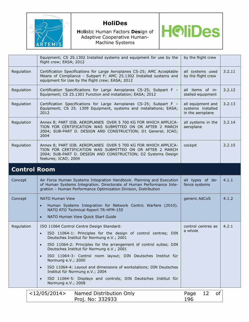
Regulation Certification Specifications for Large Aeroplanes CS-25; Subpart F – all systems used 3.2.10
HoliDes
Holistic Human Factors Design of
Adaptive Cooperative Human-
Machine Systems
<12/05/2014> Named Distribution Only
Proj. No: 332933
Page 12 of
196
Equipment; CS 25.1302 Installed systems and equipment for use by the flight crew; EASA; 2012
by the flight crew
Regulation Certification Specifications for Large Aeroplanes CS-25; AMC Acceptable Means of Compliance - Subpart F; AMC 25.1302 Installed systems and
equipment for Use by the flight crew; EASA; 2012
all systems used by the flight crew
3.2.11
Regulation Certification Specifications for Large Aeroplanes CS-25; Subpart F – Equipment; CS 25.1301 Function and installation; EASA; 2012
all items of in-stalled equipment
3.2.12
Regulation Certification Specifications for Large Aeroplanes CS-25; Subpart F – Equipment; CS 25. 1309 Equipment, systems and installations; EASA;
2012
all equipment and systems installed
in the aeroplane
3.2.13
Regulation Annex 8; PART IIIB. AEROPLANES OVER 5 700 KG FOR WHICH APPLICA-
TION FOR CERTIFICATION WAS SUBMITTED ON OR AFTER 2 MARCH 2004; SUB-PART D. DESIGN AND CONSTRUCTION; D1 General; ICAO; 2004
all systems in the
aeroplane
3.2.14
Regulation Annex 8; PART IIIB. AEROPLANES OVER 5 700 KG FOR WHICH APPLICA-TION FOR CERTIFICATION WAS SUBMITTED ON OR AFTER 2 MARCH 2004; SUB-PART D. DESIGN AND CONSTRUCTION; D2 Systems Design
features; ICAO; 2004
cockpit 3.2.15
Control Room
Concept Air Force Human Systems Integration Handbook. Planning and Execution
of Human Systems Integration. Directorate of Human Performance Inte-gration – Human Performance Optimization Division, Distribution
all types of de-
fence systems
4.1.1
Concept NATO Human View
Human Systems Integration for Network Centric Warfare (2010). NATO RTO Technical Report TR-HFM-155
NATO Human View Quick Start Guide
generic AdCoS 4.1.2
Regulation ISO 11064 Control Centre Design Standard:
ISO 11064-1: Principles for the design of control centres; DIN
Deutsches Institut für Normung e.V.; 2001
ISO 11064-2: Principles for the arrangement of control suites; DIN Deutsches Institut für Normung e.V.; 2001
ISO 11064-3: Control room layout; DIN Deutsches Institut für Normung e.V.; 2000
ISO 11064-4: Layout and dimensions of workstations; DIN Deutsches Institut für Normung e.V.; 2004
ISO 11064-5: Displays and controls; DIN Deutsches Institut für Normung e.V.; 2008
control centres as a whole
4.2.1

HoliDes
Holistic Human Factors Design of
Adaptive Cooperative Human-
Machine Systems
<12/05/2014> Named Distribution Only
Proj. No: 332933
Page 13 of
196
ISO 11064-5: Environmental requirements for control centres; DIN Deutsches Institut für Normung e.V.; 2005
ISO 11064-7: Principles for the evaluation of control centres; DIN Deutsches Institut für Normung e.V.; 2006
Regulation MIL-STD-1472G: Design criteria standard – Human engineering; U.S. De-partment Of Defence; 2012
control centres as a whole
4.2.2
Regulation MIL-HDBK-759C: Handbook for human engineering design guidelines;
U.S. Department Of Defence; 1995
control centres as
a whole
4.2.3
Healhtcare
Regulation /
Concept
IEC 62366 Medical devices – Application of usability engineering to medi-
cal devices; IEC International Electrotechnical Commission; 2007
medical devices 5.1.1
Concept Human-Centred Design in Medical Fields; N. Ando, N. Nakano, N, Tohya-
ma; 2008
health care in-
formation sys-tems
5.1.2
Concept Usability Engineering
Evaluation in the design of health information systems: application of
approaches emerging from usability engineering; A.W. Kushniruk; 2002
Cognitive and usability engineering methods for the evaluation of clin-ical information systems; A.W. Kushniruk, V.L. Patel; 2004
health care in-
formation sys-tems
5.1.3
Concept
Medical Device Use-Safety: Incorporating Human Factors Engineering into Risk Management; U.S. Department of Health and Human Services Food and Drug Administration; 2000
all systems with human interaction
5.1.4
Concept
Human Factors and Usability Engineering:
Applying Human Factors and Usability Engineering to Optimize Medi-cal Device Design; U.S. Department of Health and Human Services
Food and Drug Administration; 2011
Human Factors Engineering: A Tool for Medical Device Evaluation in Hospital Procurement Decision Making; G. Ginsburg; 2005
Introduction to the Human Factors Engineering Series; J. Gosbee; 2004
Patient Safety, Potential Adverse Drug Events, and Medical Device
Design: A Human Factors Engineering Approach; Lin et al.; 2001
all systems with human interaction
5.1.5
Regulation IEC 60601-1-6 General requirements for basic safety and essential per-formance. Collateral standard: Usability; IEC International Electrotech-
nical Commission; 2010
medical electrical equipment
5.2.1

HoliDes
Holistic Human Factors Design of
Adaptive Cooperative Human-
Machine Systems
<12/05/2014> Named Distribution Only
Proj. No: 332933
Page 14 of
196
Regulation IEC 60601-1-8 General requirements for basic safety and essential per-formance. Collateral standard: General requirements, tests and guidance
for alarm systems in medical electrical equipment and medical electrical systems; IEC International Electrotechnical Commission; 2012
medical electrical equipment
5.2.2
Regulation IEC 60601-2-33 Particular requirements for basic safety and essential performance of magnetic resonance equipment for medical diagnosis; IEC International Electrotechnical Commission; 2013
magnetic reso-nance equipment
5.2.3
Regulation IEC 60601-2-43 Particular requirements for basic safety and essential performance of X-ray equipment for interventional procedures; IEC Inter-national Electrotechnical Commission; 2010
X-ray equipment 5.2.4
Automotive
Concept Code of Practice for the Design and Evaluation of ADAS (CoP); Knapp, A.; Neumann, M.; Brockmann, M.; Walz, R.; Winkle, T.; 2009
ADAS 6.1.1
Concept /Other
Detectability Prediction for Increased Scene Awareness. David Engel, and Cristóbal Curio. IEEE Intell. Transport. Syst. Mag. 5(4):146-157 (2013)
visual attention guidance mecha-nism
6.1.2
Model/Tool ACT-R Integrated Drive Model and ACT-R Tool
Salvucci, D. D. (2006). Modelling driver behaviour in a cognitive ar-
chitecture. Human Factors, 48, 362-380.
cognitive psy-
chology model;
user model.
6.1.3
6.1.4
Regulation ISO 15005: Road vehicles – Ergonomic aspects of transport information
and control systems – Dialogue management principles and compliance procedures; DIN Deutsches Institut für Normung e.V.; 2003
dialogue man-
agement
6.2.1
Regulation ISO 15006: Road vehicles – Ergonomic aspects of transport information and control systems – Specifications for in-vehicle auditory presentation; DIN Deutsches Institut für Normung e.V.; 2012
auditory systems 6.2.2
Regulation ISO 15007: Road vehicles – Measurement of driver visual behavior with respect to transport information and control systems;CEN European Committee for Standardization; 2002
driver assistance and driver infor-mation systems
6.2.3
Regulation ISO 15008: Road vehicles – Ergonomic aspects of transport information and control systems – Specifications and test procedures for in-vehicle
visual presentation; DIN Deutsches Institut für Normung e.V.; 2011
visual presenta-tion
6.2.4
Regulation ISO 17287: Road vehicles: Ergonomic aspects of transport information
and control systems – Procedure for assessing suitability for use while driving; DIN Deutsches Institut für Normung e.V.; 2003
TICS
6.2.5
Regulation DOT HS 810 697: Crash Warning System Interfaces: Human Factors In-
sights and Lessons Learned; U.S. Department Of Transportation NHTSA;
crash avoidance
systems
6.2.6

HoliDes
Holistic Human Factors Design of
Adaptive Cooperative Human-
Machine Systems
<12/05/2014> Named Distribution Only
Proj. No: 332933
Page 15 of
196
2007
Regulation Statement of Principles, Criteria and Verification Procedures on Driver In-teractions with Advanced In-Vehicle Information and Communication Sys-tems; Driver Focus-Telematics Working Group; 2006
advanced in-vehicle infor-mation and com-
munication sys-tems
6.2.7
Regulation Legal consequences of an increase in vehicle automation; Bundesanstalt
für Straßenwesen; 2012
automation sys-
tems
6.2.8
Regulation In-Vehicle Display Icons and Other Information Elements. Volume I:
Guidelines, Volume II Final Report; U.S. Department of Transportation. Federal Highway Administration (FHWA); 2004
IVIS 6.2.9
Regulation Distraction Detection and Mitigation Through Driver Feedback; National Highway Traffic Safety Administration (NHTSA); 2013
real-time driver monitoring sys-tems; driver-state
detection and analysis
6.2.10
Regulation Multiple Reports from the AIDE (Adaptive Integrated Driver-Vehicle Inter-
face)-Project
ADAS; IVIS;
AIDE; driver state assessment sys-
tems
6.2.11
Regulation (EU) No 347/2012: Commission Regulation for certain categories of motor vehicles with regard to advanced emergency braking systems; European
Union Commission; 2012
AEBS 6.2.12
Regulation (EU) No 351/2012: Commission Regulation for installation of lane
departure warning systems in motor vehicles; European Union Commis-sion; 2012
LDWS 6.2.13
Regulation HASTE Final Report: Human Machine Interaction and the Safety of Traffic
in Europe; O.M.J. Carsten, N. Merat, W.H. Janssen, E. Johansson, M. Fowkes, K.A. Brookhuis; 2005
IVIS 6.2.14
Regulation ISO 26262 Road vehicles: Funktional Satety; DIN Deutsches Institut für Normung e.V.; 2011
electronic compo-nents in a car
6.2.15
Cross-Domain
Concept /Regulation
ISO 9241: Ergonomics of human-system interaction; DIN Deutsches Institut für Normung e.V.; 1999-2013
interactive sys-tems
7.1
Regulation ISO 9241-11: Ergonomic requirements for office work with visual display
terminals (VDTs) – Part 11: Guidance on usability; DIN Deutsches Institut
für Normung e.V.; 1999
display and con-
trols
7.2.1

HoliDes
Holistic Human Factors Design of
Adaptive Cooperative Human-
Machine Systems
<12/05/2014> Named Distribution Only
Proj. No: 332933
Page 16 of
196
Regulation ISO 9241-20: Ergonomics of human-system interaction – Part 20: Acces-sibility guidelines for information/communication technology (ICT); DIN
Deutsches Institut für Normung e.V.; 2009
ICT
7.2.2
Regulation ISO 9241-110: Ergonomics of human-system interaction – Part 110: Dia-
logue principles; DIN Deutsches Institut für Normung e.V.; 2008
dialogue princi-
ples
7.2.3
Regulation ISO 9241-143: Ergonomics of human-system interaction – Part 143: Forms; DIN Deutsches Institut für Normung e.V.; 2012
HMI: forms 7.2.4
Regulation ISO 9241-154: Ergonomics of human-system interaction – Part 154: In-teractive voice response (IVR) applications; DIN Deutsches Institut für
Normung e.V.; 2013
IVR applications 7.2.5
Regulation ISO 9241-210: Ergonomics of human-system interaction – Part 210: Hu-
man-centred design for interactive systems; DIN Deutsches Institut für Normung e.V.; 2011
interactive sys-
tems
7.2.6
Regulation ISO 9241-303: Ergonomics of human-system interaction – Part 303: Re-quirements for electronic visual displays; DIN Deutsches Institut für Normung e.V.; 2012
electronic visual displays
7.2.7
Regulation ISO 9241-304: Ergonomics of human-system interaction – Part 304: User
performance test methods for electronic visual displays; DIN Deutsches Institut für Normung e.V.; 2009
electronic visual
displays
7.2.8
Regulation ISO 9241-305: Ergonomics of human-system interaction – Part 305: Op-tical laboratory test methods for electronic visual displays; DIN Deutsches
Institut für Normung e.V.; 2009
electronic visual displays
7.2.9
Regulation ISO 9241-306: Ergonomics of human-system interaction – Part 306: Field
assessment methods for electronic visual displays; DIN Deutsches Institut für Normung e.V.; 2009
electronic visual
displays
7.2.10
Regulation ISO 9241-307: Ergonomics of human-system interaction – Part 307:
Analysis and compliance test methods for electronic visual displays; DIN Deutsches Institut für Normung e.V.; 2009
electronic visual
displays
7.2.11
Regulation ISO 9241-400: Ergonomics of human-system interaction – Part 400: Prin-ciples and requirements of physical input devices; DIN Deutsches Institut für Normung e.V.; 2007
physical input de-vices
7.2.12
Regulation ISO 9241-410: Ergonomics of human-system interaction – Part 410: De-sign criteria for physical input devices; DIN Deutsches Institut für
Normung e.V.; 2012
physical input de-vices
7.2.13
Regulation ISO 9241-420: Ergonomics of human-system interaction – Part 420: Se-lection of physical input devices; DIN Deutsches Institut für Normung
e.V.; 2011
physical input de-vices
7.2.14

HoliDes
Holistic Human Factors Design of
Adaptive Cooperative Human-
Machine Systems
<12/05/2014> Named Distribution Only
Proj. No: 332933
Page 17 of
196
3 Aeronautics Domain
3.1 HFI Concepts in Aeronautics Domain
3.1.1 Concept: The Human Factors Case
Reference The Human Factors Case: Guidance for Human Factors Integration;
Edition 2.0.; EUROCONTROL; 2007
CREDOS – Human Factors Case Report; Eurocontrol; 2009
Application of the concept
Domain: Aeronautics System: ATM (Air Traffic Management System)
Addressed HF-issues
The HF Case addressed a wide spectrum of HF-Issues, which are classified
into six broad main categories. Each category is broken down in further sub-categories. The provided organisational cluster of issues is called “HF Pie”
classification tool. Definitions for the HF-issues are also given by the concept.
HF-issues
Main Category
Definition
Working Environ-
ment
The category includes the working space, general equipment/furniture
used, and the physical environment in which people work.
Organisation and
Staffing
The wide category covers issues related to organisational management, people management and personal factors.
Procedures, Roles
and Responsibili-
ties,
Procedures (standard and emergency/abnormal), roles (posi-
tion/propose/function having in an organisation), responsibilities and working method(task demand and complexity)
Teams and Com-
munication
A comprehensive category addressing issues related to how individuals
work and communicate with each other on shared goals and tasks. There are different aspects of team interaction and communications (e.g. in-formation requirement, communication methods) covered.
Training and De-velopment
“The systematic development of the knowledge, understanding, skill and attitude behaviour patterns required by an individual in order to ade-
quately
perform a given task” (Eurocontrol 2007; p. 71)

HoliDes
Holistic Human Factors Design of
Adaptive Cooperative Human-
Machine Systems
<12/05/2014> Named Distribution Only
Proj. No: 332933
Page 18 of
196
Human in System This highlights that the human is a crucial part of the system. Subcate-
gories are: human-machine interaction (input and output devices, information requirements, alert signals, human-machine interface, allocation of function between human
and machine) and system (reliability, automation and new technology)
Within the HF Case Approach, HF-issues are assessed of how they potentially impact the human performance in the system. Twelve critical HF impacts are
specified: acceptance, cognitive processes, comfort, error, fatigue, job satis-
faction, motivation, situational awareness, skill change, stress, trust, and workload.
Proposed course of action
The HF Case Process is well-defined and consists of five specific stages: Stage 1: Fact Finding:
o objective: the project scope from an HF perspective, is to identify what will change, who will be affected, and how they will be af-
fected. o steps: gather information, initial HF assessment, review meeting
o output: Initial HF Assessment o support given: Fact Finding Template and Guidance for Comple-
tion; HF Pie Stage 2: Issues Analysis:
o objective: identify and prioritize the project specific HF Issues and consider their potential impact on human performance and on the system, identify mitigation strategies
o steps: identify HF Issues and their impacts (group workshop or
expert interviews), prioritize the HF Issues and their impacts, Draft the Issues Analysis Report
o output: Issues Analysis Report
o support given: Guideline to choose the appropriate approach (group workshop or expert interview); Group Workshop Guide-
lines; HF Issues Descriptions; Definitions for HF Impacts on Hu-
man Performance; Issues Analysis Approach Feedback Form; Is-
sues Analysis Report Outline; Example Criteria and Definitions for High, Medium and Low; Example of Assigning Criteria to Issues
Stage 3: Action Plan:
o objective: describe HF Actions and mitigation strategies neces-
sary to address the selected relevant HF Issues (listed in Issues
Analysis Report).

HoliDes
Holistic Human Factors Design of
Adaptive Cooperative Human-
Machine Systems
<12/05/2014> Named Distribution Only
Proj. No: 332933
Page 19 of
196
o steps:
Identify HF Actions required: mitigation strategies
simulations
studies (e.g. literature review; cognitive work analy-
sis; workload assessment; error investigations) Determine monitoring arrangements for the HF effort;
Draft the Action Plan
o output: Action Plan o support given: Action Plan Content and Elements
Stage 4: Actions Implementation
o objective: implement the actions defined in the Action Plan, val-idate the results, and report the HF conclusions and findings in
the HF Case Report. o steps: carry out the Actions; validate the actions findings; draft
the HF Case Report o output: HF Case Report o support given: : HF Actions Findings Template; HF Case Report
Outline
• Stage 5 - HF Case Review: o objective: review the quality of the conducted HF Case-Process
o steps: Review process; draft the HF Review Report o output: HF Case Review Report o support given: : HF Case Review Report Outline
The concept primarily proposes Human Factors Management activities. These
are structured very clearly and described in detail. The format for drawing conclusions is also given. On the contrary, the Human Factors Engineering
activities are not closely considered.
System development stages addressed by the concept
The HF Case Concept is a management process that enables the ad-
dressing and management of HF-Issues systematically throughout a
project lifecycle (8 stages) in order to improve human performance
within the system. The HF Case process can be initiated at any stage of the project lifecy-
cle, but it is recommended to do so as early as possible, because of
greater prospects to handle HF-Issues satisfactorily and cost efficiently.
HoliDes
Holistic Human Factors Design of
Adaptive Cooperative Human-
Machine Systems
<12/05/2014> Named Distribution Only
Proj. No: 332933
Page 20 of
196
The HF Case Process consists of 5 defined stages. The authors only
point out that the HF Case Process should run in parallel to the project lifecycle. However, they do not concretize when exactly the HF Case-
stages/activities should occur in correspondence with the project lifecy-
cle processes.
The HF Case does not refer to the V-Model, rather it only emphasises, that the application of HF is a core part of the system design evaluation
and implementation.
Proposed Tools
Eurocontrol purposed a HF Case e-tool, which is a standalone application to log and track HF case data throughout the five stages of the HF Case process
for any ATM project. Using the tool requires the completion of the Eurocon-trol HF Case Training Course and to sign a licence agreement
STRENGTHS-WEAKNESSES Analysis
Strengths:
The concept provides a practical framework to address and manage the HF issues systematically throughout a project lifecycle (e.g. system de-
sign, evaluation, implementation and operation). The concept has been composed to support a development process of
complex cooperative systems (ATM), where interactions occur between a number of humans and machines. As a result of it the concept takes
a wide range of HF issues under consideration: o An extensive structured map of HF issues (classification and rep-
resentations of HF-issues at different level of details) is given.
o The work process of how to identify the relevant HF-issues in the
project is defined clearly. It establishes a basis for the HF inte-gration process.
The HF Case provides a well-specified and structured course of action
for HF Integration process. The objectives, work steps, deliverables and outputs from each stage of the process are clarified very well. De-
tailed Guidelines for planned activities and templates for outcomes are
given.
The application of the concept, mainly drawing conclusions from every
stage, enables for a good overview and makes the HF work status and achieved results in the project transparent for all partners/stakeholders
involved in the development process.
HoliDes
Holistic Human Factors Design of
Adaptive Cooperative Human-
Machine Systems
<12/05/2014> Named Distribution Only
Proj. No: 332933
Page 21 of
196
The concept has matured with its application. Since the first version
was published in 2004, more than a dozen HF Cases have been carried out for various EATM projects. As a result, a new revised version has
been composed in 2007.
The HF Case establishes a matured process/guidance of HF integration
throughout a project lifecycle that could be entirely or in large parts adopted for AdCos and be integrated in the HF-RTP. The concept as a
HF management “tool” does not set a large focus on the domain- spe-
cific HF topics. A universal cross-domain application of the HF Case is conceivable.
The concept provides a structured and comprehensive representation
of various HF-issues, which could be important for the development of complex systems. It could deliver a useful reference/checklist/overview
for AdCos development and be inserted in the HF-RTP. Weaknesses:
The objective of the approach is the HF management throughout a pro-ject. It does not deal with the human factors topics and activi-ties/methods directly. It only emphasises that HF actions and mitiga-
tion strategies (necessary to address the selected relevant HF Issues)
should be planned, implemented and documented. The HF Case Process does not correspond to the V-Model.
3.1.2 Concept: Integrated Human Centred Systems Approach to the Development of Advanced Cockpit and ATM Systems
Reference Integrated Human Centered Systems Approach to the Development of Ad-
vanced Cockpit and Air Traffic Management Systems; R.J. Hansman, J.K. Ku-
char, J.-P. Clarke, S. Vakil & R. Barhydt; 1997
Application of the concept
Domain: Aeronautics
System: advanced cockpit and ATM information systems.
Case studies applying the concept focussed on the following systems and
procedures “intent information on cockpit traffic display”, “hazard alerting
and conflict probe and design issues”, and “minimal noise approach and de-parture procedures”.
HoliDes
Holistic Human Factors Design of
Adaptive Cooperative Human-
Machine Systems
<12/05/2014> Named Distribution Only
Proj. No: 332933
Page 22 of
196
Addressed HF-issues
Automation and new technology
input devices output devices
information requirements
alert signals
allocation of function between human and machine
Further issues that are covered by the concept are:
system performance (new system must improve performance of the coupled system, i.e. humans)
situational awareness
attentions limitations information and task overload
understanding of the automation criteria changes in authority
changes in communication modes loss of „party line“ information
unexpected compensatory behavior human acceptance and trust of automation
human reliance in automation
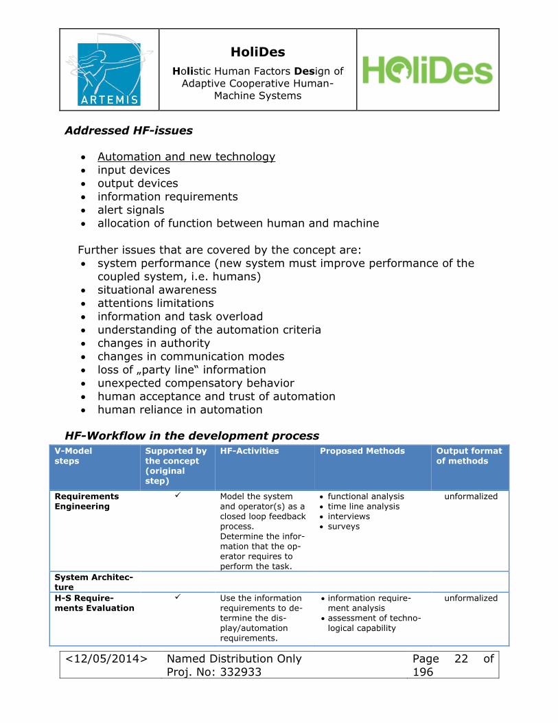
HF-Workflow in the development process
V-Model
steps
Supported by
the concept (original step)
HF-Activities
Proposed Methods
Output format
of methods
Requirements
Engineering
Model the system
and operator(s) as a closed loop feedback process.
Determine the infor-mation that the op-erator requires to
perform the task.
functional analysis
time line analysis interviews surveys
unformalized
System Architec-ture
H-S Require-ments Evaluation
Use the information requirements to de-termine the dis-
play/automation requirements.
information require-ment analysis
assessment of techno-
logical capability
unformalized
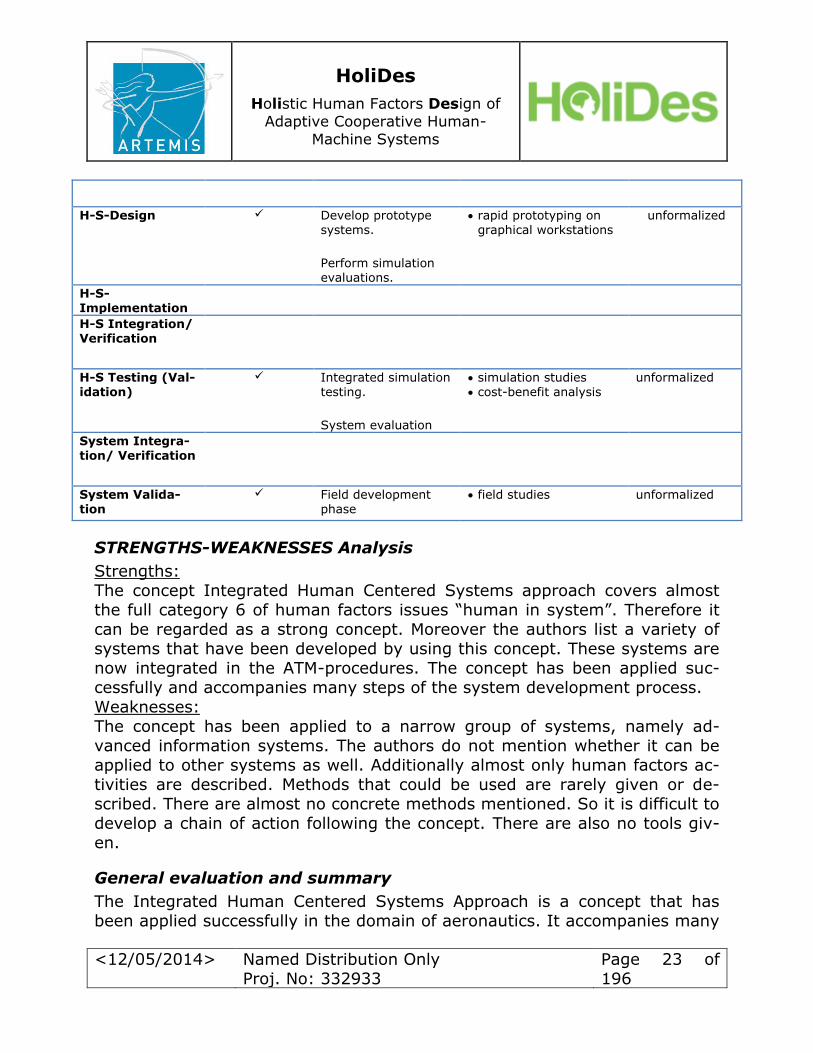
HoliDes
Holistic Human Factors Design of
Adaptive Cooperative Human-
Machine Systems
<12/05/2014> Named Distribution Only
Proj. No: 332933
Page 23 of
196
H-S-Design Develop prototype systems.
Perform simulation evaluations.
rapid prototyping on graphical workstations
unformalized
H-S-Implementation
H-S Integration/ Verification
H-S Testing (Val-idation)
Integrated simulation testing.
System evaluation
simulation studies cost-benefit analysis
unformalized
System Integra-tion/ Verification
System Valida-tion
Field development phase
field studies unformalized
STRENGTHS-WEAKNESSES Analysis
Strengths:
The concept Integrated Human Centered Systems approach covers almost the full category 6 of human factors issues “human in system”. Therefore it can be regarded as a strong concept. Moreover the authors list a variety of
systems that have been developed by using this concept. These systems are now integrated in the ATM-procedures. The concept has been applied suc-
cessfully and accompanies many steps of the system development process.
Weaknesses:
The concept has been applied to a narrow group of systems, namely ad-
vanced information systems. The authors do not mention whether it can be
applied to other systems as well. Additionally almost only human factors ac-
tivities are described. Methods that could be used are rarely given or de-scribed. There are almost no concrete methods mentioned. So it is difficult to
develop a chain of action following the concept. There are also no tools giv-
en.
General evaluation and summary
The Integrated Human Centered Systems Approach is a concept that has
been applied successfully in the domain of aeronautics. It accompanies many
HoliDes
Holistic Human Factors Design of
Adaptive Cooperative Human-
Machine Systems
<12/05/2014> Named Distribution Only
Proj. No: 332933
Page 24 of
196
steps of the system development process and offers different opportunities
to integrated human’s limitations and capabilities in the field of “human in system”. The authors mention many issues that arise in the co-operation of
humans and automation and that can be tackled by the usage of the con-
cept. Even though there are only a few methods mentioned the concept can
be regarded as a strong concept, since use cases show its strength. Addi-tionally the lack of methods offers flexibility such that the concept can be ap-
plied to many different systems.
3.1.3 Engineering Process and HF Integration Concept applied by Honeywell
Engineering process
The process is described in two major phases. First is the development of the technology, which has the following steps:
1. Gather the requirements 2. Evaluate benefits/interests in the technology
3. Verify the feasibility of the technology 4. Create the realistic prototype
5. Evaluate the risks of the development and create mitigation strategies
The second phase is the product realization that turns the technology into a
product applying the required safety standards. The steps are: 1. Create the product that complies with all applicable standards and
restrictions 2. Undergo certification process 3. Deploy and support the product
The two phases are rather separate though interaction exists during execu-
tion of each of them. Development of the technology
The development of the technology is based on the standard industrial
process of manufacturing the technology readiness level, (TRA at wiki). The process is then broken down into a sequence of steps, in which the
risks are identified and mitigated and the technology matures from ini-
tial ideas into a reliable prototype. The steps (technology readiness
levels, TRLs) are:
TRL 1: Basic principles observed and reported TRL 2: Technology concept and/or application formulated

HoliDes
Holistic Human Factors Design of
Adaptive Cooperative Human-
Machine Systems
<12/05/2014> Named Distribution Only
Proj. No: 332933
Page 25 of
196
TRL 3: Analytical & experimental critical function and/or charac-
teristic proof-of-concept TRL 4: Component and/or breadboard validation in laboratory
environment
TRL 5: Component and/or breadboard validation in relevant envi-
ronment TRL 6: System/subsystem model or prototype demonstration in a
relevant environment (ground or space)
TRL 7: System prototype demonstration in a space environment TRL 8: Actual system completed and "Flight qualified" through
test and demonstration (ground or space)
TRL 9: Actual system "Flight proven" through successful mission operations
The process is usually adjusted to the working environment of each company that applies it and the adjustment is considered confidential (such as in case
of Honeywell).
HF integration concept
Maturing the technology readiness is a general process where no explicit
strategies for integration of human factors are mentioned. It is up to each
user of the process to define his/her own strategy. This strategy is usually considered confidential.
HF integration reflects the TRLs and usually adds specific actions to be taken and verified at each TRL. This implies that in the beginning the development team needs to identify
1. Whether there are any HF aspects in the technology 2. At which TRL the HF aspects should be addressed
3. Who are the HF experts to be contacted at respective TRLs
During execution of the development process, each TRL affected by HF is-
sues is extended for activities the HF team should undergo. The results of the activities are documented in prescribed artefacts such as
TRL 2:
Intended function definition
Task analysis and functional allocation
Preliminary test plan TRL 3:
Preliminary user interface
Feedback of a representative user to the preliminary user
interface

HoliDes
Holistic Human Factors Design of
Adaptive Cooperative Human-
Machine Systems
<12/05/2014> Named Distribution Only
Proj. No: 332933
Page 26 of
196
Evaluation via simple HF assessment techniques (user survey,
design walk-through etc.) Evaluation reports
TRL 4
Updated user interface
Evaluation based on more sophisticated techniques (experiments in laboratory environment with target users)
Evaluation reports
TRL 5 Preliminary HF certification strategy
Continuous evaluation of user interface being developed
(experiments for the integrated system, not only the interface itself)
Evaluation reports Technology transition plans (describing how HF issues will affect
the productization) TRL 6
Continuous evaluation
Evaluation reports
HF risk mitigation strategy Compliance to HF standard and regulations
Similar to the engineering process, transition to a higher TRL needs to be au-thorized by independent board of experts during a review process called on by the development team.
3.2 HF and Safety Regulations in Aeronautics Domain
3.2.1 Guidelines for the Certification, Airworthiness and Operational
Use of Electronic Flight Bags
Reference
AC-120-76B: Guidelines for the Certification, Airworthiness, and Operational Use of Electronic Flight Bags; FAA; 2012
Application of the regulation
Domain: Aeronautics
System: Electronic Flight Bag
Addressed HF-issues
Working Environment

HoliDes
Holistic Human Factors Design of
Adaptive Cooperative Human-
Machine Systems
<12/05/2014> Named Distribution Only
Proj. No: 332933
Page 27 of
196
Training and Development
Human in System
Demand of HF-activities during development process
Regulations on design of EFB HW and SW
Regulations on HMI aspects of EFB applications
Addressed system development stages
System architecture
HW-SW Design HW-SW Implementation
System Validation
Additional information
There are 2 EFB hardware classes and 3 software types (A, B, C). HMI Design regulations for Class 2 EFBs
o The system must not be used as primary source of information. The beneficial safety function may augment, elaborate, or supplement
information coming from a primary information source whether it is presented in the primary field of view displays or the out-the-
window view, but it must not replace it. o Designing the User Interface (UI) of an EFB Class 2 platform to de-
crease the risk of over compliance o Designing UI of a safety beneficial function to prevent unintended
usage, and/or o Design the operational procedure for the safety beneficial function
to prevent transfer of responsibility from the aircrew to the safety
beneficial function
o The UI of an EFB platform must be compatible with the flight deck in terms of basic design principles including consistency of colour cod-
ing, symbols, etc., but it should not elicit higher expectations relat-
ed to robustness of the system functionality than the system is able to provide.
o One of the most important concerns of the regulatory authorities is
usage of the EFB Type B applications for navigation purposes. This
means displaying of the own ship in relation to the navigation aids
as magnetic rose, arc, navigational aids, etc. The concern of the
regulatory authorities is given by the lower reliability and robust-ness of the EFB application to display navigational data. This is a

HoliDes
Holistic Human Factors Design of
Adaptive Cooperative Human-
Machine Systems
<12/05/2014> Named Distribution Only
Proj. No: 332933
Page 28 of
196
valid concern as using the EFB Class 2 device as primary source of
information for navigation of the aircraft could impair flight safety.
o The own ship position could be used when displaying strategic
weather along the route, help the pilot to avoid the impaired weath-
er conditions, etc. The same logic as with displaying of the own ship position during the flight besides the approved display of own ship
position on AMM could be applied when investigating possibilities to
display other aircraft position using ADS-B In data on EFB Class 2 hardware. If the data is used for strategic purposes and displayed in
a way that it prevents the aircrew from using it for tactical naviga-
tion manoeuvring, then may be even possible to host such feature on non-certified EFB hardware.
Class 3 EFB EFBs installed in accordance with applicable airworthiness regulations.
Refer to AC20-173 for guidance on the installation of EFB components. For this class read and write interaction with avionic is allowed. o Type A EFB Software
Type A EFB SW applications include pre-composed, fixed presenta-
tions of data currently presented in paper format. Type A applica-tions are typically intended to be used on the ground or during non-
critical phases of flight. Type A application software may reside on any EFB hardware classification. These applications do not need any formal approval. The operator must possess evidence demonstrat-
ing that operational requirements are met when using Type A soft-ware applications. This means that the operator can use the appli-
cation after successful completion of the user/operator evaluation (including flight crew training, checking and currency require-
ments). o Type B EFB Software
Type B EFB SW applications include dynamic, interactive applica-
tions that can manipulate data and presentation for operationally
required and other paper reference materials. Type B applications
are applications that are intended for use during critical phases of flight. Type B application software may reside on any EFB hardware
classification. These applications do not need any formal approval.
The operator must possess evidence demonstrating that operational
requirements are met when using Type B software applications.
This means that the operator can use the application after success-

HoliDes
Holistic Human Factors Design of
Adaptive Cooperative Human-
Machine Systems
<12/05/2014> Named Distribution Only
Proj. No: 332933
Page 29 of
196
ful completion of the user/operator evaluation (including flight crew
training, checking, currency requirements and FSB reports). Type B applications require a validation period to ensure the reliability of
the EFB functions prior to the removal of the applicable paper doc-
uments.
o Type C EFB Software Type C EFB SW applications include intended functions for commu-
nications, navigation, and surveillance that require FAA design,
production and installation approval. Type C applications are FAA approved software using RTCA/DO-178B compliance or other ac-
ceptable means. Approved software applications will have an FAA
approved flight manual supplement. Type C applications are for airborne functions with a failure condition classification considered
to be a major hazard or higher. HMI guidelines (Part 12 – EFB System Design Considerations)
o Legibility of Text: Text displayed on the EFB should be legible to the typical user at the intended viewing distance(s) and under the full range of lighting conditions expected on a flight deck, including use
in direct sunlight.
o Flight crew Workload: The EFB software design should minimize flight crew workload and head-down time.
o Human/Machine Interface: The interface design (including, but not limited to, data entry methods, color-coding philosophies, terminol-ogy, and symbology) should be consistent across the EFB and vari-
ous hosted applications.
3.2.2 Human Factors Considerations in the Design and Evaluation of
Electronic Flight Bags
Reference
DOT-VNTSC-FAA-03-07: Human Factors Considerations in the Design and Evaluation of Electronic Flight Bags; FAA; 2003
Application of the regulation
Domain: Aeronautics
System: Electronic Flight Bag
Addressed HF-issues
Human in System:
HoliDes
Holistic Human Factors Design of
Adaptive Cooperative Human-
Machine Systems
<12/05/2014> Named Distribution Only
Proj. No: 332933
Page 30 of
196
o Legibility – Lighting Issues.
o General use of colours o Legibility of Text—Character
o Legibility of Text—Typeface Size and Width
o Legibility of Text—Spacing for Readability
o Non-Text Display Elements
Demand of HF-activities during development process
Regulations on design and evaluation of EFB SW
Addressed system development stages
System architecture HW-SW Design
HW-SW Implementation System Validation
3.2.3 Airworthiness and operational criteria for the approval for EFB
Reference
NPA 2012-02: Airworthiness and operational criteria for the approval for Electronic Flight Bags; EASA; 2012
Application of the regulation
Domain: Aeronautics
System: Electronic Flight Bag
Addressed HF-issues
Training and Development Human in System
Demand of HF-activities during development process
Regulations on design and evaluation of EFB SW
Addressed system development stages
System architecture
HW-SW Design
HW-SW Implementation System Validation

HoliDes
Holistic Human Factors Design of
Adaptive Cooperative Human-
Machine Systems
<12/05/2014> Named Distribution Only
Proj. No: 332933
Page 31 of
196
Additional information
Procedures to Mitigate and/or Control Workload: Procedures should be
designed to mitigate and/or control additional workloads created by us-
ing an EFB system.
Legibility of Text: Text displayed on the EFB should be legible to the
typical user at the intended viewing distance(s) and under the full
range of lighting conditions expected on a flight crew compartment, in-cluding use in direct sunlight. Users should be able to adjust the screen
brightness of an EFB independently of the brightness of other displays
on the flight crew compartment. In addition, when automatic bright-ness adjustment is incorporated, it should operate independently for each EFB in the flight crew compartment. Buttons and labels should be
adequately illuminated for night use.
3.2.4 EFB Application Design Assessment
Reference EFB Application Design Assessment; Honeywell; 2014
Application of the regulation
Domain: Aeronautics
System: Electronic Flight Bag
Addressed HF-issues
HMI: o use of colours
o legibility (lighting conditions, text, symbols, adjustment to
changed human vision by older users)
Demand of HF-activities during development process
Guidelines for graphical design of EFB SW
Addressed system development stages
HW-SW Design
System Validation

HoliDes
Holistic Human Factors Design of
Adaptive Cooperative Human-
Machine Systems
<12/05/2014> Named Distribution Only
Proj. No: 332933
Page 32 of
196
3.2.5 Analysis of Human Performance Risks and Benefits of Adaptive
Systems
Reference
FAA project 05-02, Task Number 09-AJP61FGI-0114: Analysis of Human Per-
formance Risks and Benefits of Adaptive Systems, Final Report; Honeywell;
2012
Application of the regulation
Domain: Aeronautics Generic
System: Adaptive flight deck systems
Addressed HF-issues
Training and development (training requirements) Procedures, roles and responsibilities
Human in System: situation awareness, distraction, workload, user ac-ceptance)
Proposed HF-activities during development process
Guidelines and recommendations for architecture and design of adap-
tive systems
Addressed system development stages
Requirements engineering
System architecture HW-SW requirement evaluation
HW-SW Design
HW-SW implementation
HW-SW testing System Validation
Additional information
Adaptive Systems, Automation, and Perception of Non-
Determinism
o Adaptive systems that appear to be non-deterministic should be avoided. Many elements of an adaptive system can cause it to be

HoliDes
Holistic Human Factors Design of
Adaptive Cooperative Human-
Machine Systems
<12/05/2014> Named Distribution Only
Proj. No: 332933
Page 33 of
196
perceived as non-deterministic, and these elements should be as-
sessed on a case by case basis. o Adaptive systems may have many of the same benefits as good full
time automation, but adaptive systems carry inherently more risk
related to predictability. Hence adaptive systems should be used ra-
ther than good full time automation only when the adaptive nature provides a very clear benefit over an “all the time” automation fea-
ture or function.
o Adaptations that turn on and off too frequently or too infrequently should be avoided.
o Triggers which are less observable by the user (e.g. operator meas-
urement or task tracking) should be used cautiously since they may appear to be non-deterministic and carry more risk.
Overall Adaptive System Risks and Benefits o All potential adaptations pose some risk to pilot performance in ad-
dition to potential benefits. These risks and benefits need to be considered together in determining whether an adaptive system is acceptable or not.
o Adaptive systems should minimize negative impacts on all aspects
of pilot performance. o Adaptive systems should maintain or improve pilot situation aware-
ness compared to the level normally achieved without the adaptive system, except when near-term performance takes priority.
o Adaptive systems should maintain or improve the ability of the flight
crew to stay engaged and “in the loop” compared to that achieved without the adaptive system.
o Adaptations that change control authority between pilot and auto-mation should be avoided; if necessary, they should be done spar-
ingly and accompanied by salient feedback. o Adaptive systems that provide information or recommendations, but
still allow pilots to make decisions and selections are more accepta-
ble than adaptive systems that make decisions and have control au-
thority.
o Adaptations that provide a last resort “safety of flight” function may be acceptable even if they have human performance risks.
o The benefit of an adaptive system should be obvious to the pilots; if
it is not, pilots will be less likely to accept the adaptive system and
may consider it to be a nuisance or distraction.

HoliDes
Holistic Human Factors Design of
Adaptive Cooperative Human-
Machine Systems
<12/05/2014> Named Distribution Only
Proj. No: 332933
Page 34 of
196
o A variety of sources of potential risks of adaptive systems should be
assessed before the systems are deemed acceptable. o Adaptive system risk assessment should evaluate unintended nega-
tive consequences.
o Balancing pilot workload is one of the main drivers of adaptive sys-
tems which are designed specifically to improve pilot-system per-formance. However, workload should be assessed for both positive
and negative changes due to introduction of adaptive systems.
o The impact of the introduction of an adaptive system on training re-quirements needs to be considered.
o The Adaptive systems should minimize the likelihood of adaptation-
induced oscillations that would severely disrupt flight crew workflow. Guidelines related to Adaptive System Components
o Triggers: Operator measurement and task tracking triggers should
be utilized with caution until the state-of-the-art is more mature.
All trigger types other than operator measurement and
task tracking are inherently low risk and should be
considered as potentially acceptable triggers for adaptive systems.
The number of triggers that are combined to activate any adaptation should be kept relatively small.
o Processing Types:
More sophisticated processing methods (e.g., neural nets, Bayesian models) that are less transparent and more com-
plex than other types of processing (e.g., simple produc-tion rules) can be considered if they provide more accu-
rate, predictable, and timely adaptations o Adaptation Types:
Task sharing adaptations that are informational in nature
are more acceptable from a pilot performance perspective
than those that are action or control oriented.
Task offloading involving lower priority tasks are more acceptable from a pilot performance perspective than those
involving high priority or flight critical tasks.
The adaptive offloading of large tasks or function chunks
should be avoided because it can cause greater risk of
pilots losing situation awareness and being out of the loop.

HoliDes
Holistic Human Factors Design of
Adaptive Cooperative Human-
Machine Systems
<12/05/2014> Named Distribution Only
Proj. No: 332933
Page 35 of
196
Adaptive systems that generate a list of information to add
or subtract, which pilot can select, are more acceptable than systems that automatically adding/subtracting
information. However, the extra workload of systems that
require pilot selection or activation of information content
adaptations must be considered. Level of abstraction/integration adaptations are potentially
both high risk and high benefit, so the acceptability must
be evaluated on a case by case basis. Even though prioritisation adaptations are informational, to
be acceptable they must assure that pilots don’t over-rely
on the information in safety-critical situations. An adaptive system that could assist pilots with returning
to an interrupted task as well as remind them of a missed or forgotten action that could could turn into more serious
problems, should be considered to be potentially high benefit and low risk.
Adaptations that intentionally interrupt current pilot tasks
should be used sparingly and are recommended only if the
automation can unequivocally determine that there is imminent danger due to pilots not attending to key tasks or
information. Adaptations of Interface Features are generally low risk
adaptations, especially if the adaptation is implemented in
a way that gets pilot attention without being overly intrusive or annoying.
Adaptive changes from visual to aural should be minimised to avoid too much aural information on the flight deck and
potential interference with other aurally presented information. Changes from aural to visual information
should be assessed for the possibility of misleading pilots
into assuming the problem or condition that was being
aurally indicated went away.
Risks related to adaptive system characteristics o Key adaptive system characteristics that should be assessed as risks
to pilot performance include authority, complexity, accuracy, sensi-
tivity, robustness, novelty, and pilot acceptance.
HoliDes
Holistic Human Factors Design of
Adaptive Cooperative Human-
Machine Systems
<12/05/2014> Named Distribution Only
Proj. No: 332933
Page 36 of
196
o Adaptive systems should include predictability and transparency
features, which make automatic changes (and anticipated changes) as obvious to the pilots as possible.
o While a large number of adaptive system characteristics were iden-
tified that are relevant to adaptive system risk, all the characteris-
tics are inter-related and issues with one characteristic should be assessed in conjunction with other characteristics.
o Triggers and adaptations are likely more observable by pilots than
the processing. Therefore trigger and adaptation characteristics such as complexity and transparency should be assessed more care-
fully than processing characteristics.
Operational Use Factors Affecting Adaptive System Risks o The type of application that the adaptive system is being utilised for
should be considered in assessing its acceptability. o The operational situation in which the adaptive system is being uti-
lized should be considered in assessing its acceptability Implementation Considerations for Adaptive Systems
o All adaptive systems should regularly and saliently communicate
their status, intention and any issues associated with their perfor-
mance. o If adaptations are reversible, pilots should have a quick and easy
way to override them. o Actions that have recently been performed by pilots should general-
ly not be overridden with automatic adaptations.
o The interaction style of the adaptive system should be assessed as a key component of the adaptive system; it can have a significant im-
pact on the overall risk and benefit of the system. o The amount of required pilot interaction with an adaptive system
should consider factors other than pilot workload. o Turning adaptations on and off may require different design ap-
proaches and result in different triggers for activating and de-
activating the adaptation.
o Acceptable adaptive systems should have explicit features that miti-
gate the potential nuisance/distraction/disruption potential of the adaptations.
o If adaptive systems have incomplete information for triggering the
adaptation, it should inform the pilot and first ask whether he/she
wants it to proceed on information available or wait until all infor-
mation is available to engage the adaptation.

HoliDes
Holistic Human Factors Design of
Adaptive Cooperative Human-
Machine Systems
<12/05/2014> Named Distribution Only
Proj. No: 332933
Page 37 of
196
o Utilising an operator initiated trigger will realise many risk mitiga-
tions with minimal costs. o When tuning adaptive systems for invoking sensitivity it is advisable
to bias them to minimize false positives and not misses.
3.2.6 Human Factors Design Standard: General design requirements
Reference Human Factors Design Standard; Chapter 2: General design requirements;
FAA; 2003
Application of the regulation
Domain: Aeronautics System: all systems in the airplane
Addressed HF-issues
Knowledge, skill, and ability requirements; Personal Factors; Training; Task
Demand; Human machine interaction; System Reliability Demand / Proposi-tion of HF-activities during development process
Additional information
Chapter 2 of the Human Factors Design Standard regulates the general de-
sign requirements for systems and equipment. It describes basic design ele-ments like the durability of systems, their reliability and the appropriate allo-
cation of their functions. General rules for simplicity, consistency, standardi-zation and the user-centered perspective are explained. Systems shall be de-
signed to minimize user actions and training requirements but maximize hu-man performance. Safety of systems is ruled in this chapter, too. A fail-safe
design and the error resistance are two examples therefore. Systems shall
be easy to maintain and help has to be provided in case of difficulties during
operating or maintaining software, systems or equipment. There is no HF-workflow (activities during the development process) given.
3.2.7 Human Factors Design Standard: Automation
Reference Human Factors Design Standard; Chapter 3: Automation; FAA; 2003
Application of the regulation
Domain: Aeronautics
HoliDes
Holistic Human Factors Design of
Adaptive Cooperative Human-
Machine Systems
<12/05/2014> Named Distribution Only
Proj. No: 332933
Page 38 of
196
System: all systems in the airplane using automation
Addressed HF-issues
Noise; Knowledge, skill, and ability requirements; Physiological Factors;
Stress; Preoccupations; Training; Procedures; Roles; Responsibilities; Com-
plexity; Team interaction; Human machine interaction; System Reliability,
Automation and new technology
Proposed HF-Activities
1. Design of automation should begin by choosing the human-centered criteria (goals) of the system and then defining the functions that
the system will perform. (analysis) 2. When new automation is introduced, the designers shall consider the
possibility of negative effects on team coordination. (analysis) 3. The overall impact of automation shall be thoroughly examined be-
fore implementation to ensure that changes do not result in addi-tional complexities, loss of situational awareness, or possibilities for
error. (analysis/evaluation) 4. Contextually valid human-in-the-loop experiments and simulations
should be conducted to validate and refine automated system de-sign. (evaluation)
5. Possible interactions with other tools, system functions, and user tasks shall be evaluated when new automation is designed. (evalua-
tion) 6. New automation components shall be tested with the complete sys-
tem, including other automated components of the system, to en-
sure they function together as an effective whole. (evaluation)
7. Automated systems shall be tested under normal modes of operation and under failure modes of the automation. (evaluation)
8. Automated systems shall be tested in a realistic operational envi-
ronment with representative users before implementation to ensure that operator performance is not compromised and workload is not
increased. (evaluation)
HF workflow
Requirements Engineering; Hardware-Software Requirements; System Inte-
gration/Verification; Hardware-Software Testing

HoliDes
Holistic Human Factors Design of
Adaptive Cooperative Human-
Machine Systems
<12/05/2014> Named Distribution Only
Proj. No: 332933
Page 39 of
196
Additional information
Chapter “Adaptive automation” integrated, including hints under which condi-tions adaptive automation shall or shall not be implemented.
3.2.8 Human Factors Design Standard: Displays and printers
Reference
Human Factors Design Standard; Chapter 5: Displays and printers; FAA; 2003
Application of the regulation
Domain: Aeronautics
System: all systems in the airplane using displays and printers
Addressed HF-issues
work place layout; physical limitations;
Human machine interaction; System Reliability
Additional information
The regulation describes design and position requirements of displays and
printers. There are no HF-activities or HF workflow described. This chapter only addresses visual displays used for information output. Touch screen dis-
plays and visual indicators are not regulated in this chapter. General rules outline how output devices have to be presented on the displays like the leg-
ibility, the avoidance of unnecessary markings and contrast and brightness. Location of the displays is explained in connection with the line of sight and
the optimum vertical and horizontal visual fields. Specifics of different types
of displays are described in the following subchapters. When printers should
be used, where they shall be located and how information has to be present-ed on the printed tapes is the content of the next subchapter. The rule ends
with the use of plotters and recorders and accommodation requirements for
people with disabilities.
3.2.9 Human Factors Design Standard: Computer-human interface
Reference
Human Factors Design Standard; Chapter 8: Computer-human interface; FAA; 2003

HoliDes
Holistic Human Factors Design of
Adaptive Cooperative Human-
Machine Systems
<12/05/2014> Named Distribution Only
Proj. No: 332933
Page 40 of
196
Application of the regulation
Domain: Aeronautics System: all systems in the airplane
Addressed HF-issues
Physical limitations;
Working Method; Human machine interaction (especially Input and Output devices);
System Reliability
Additional information
Chapter 8 contains very detailed instructions about how information has to be presented on the display, how the menu navigation has to be implement-
ed, how input devices shall work and similar rules with the aim to supporting the crew fulfill their task as well and easily as possible. There are no HF-
activities or HF workflow described. The regulation is divided into 18 sub-chapters.
The first subchapter deals with screen design. Besides general principles like
simplicity and a minimal information density, further rules are described like
the location or highlighting of messages in context with their importance, to help the crew get the most important information as fast as possible.
Text entry and display is the next subchapter in this regulation. It rules pos-sibilities of input devices for the crew and functions they are able to use.
The third subchapter explains the presentation specifications of graphical in-formation on the display. Different kinds of graphs are described as well as the possibilities of the flight crew to manipulate them, like zooming in for ex-
ample.
The next subchapter deals with concealed information. An indication of the suppression of information shall be provided if there is a temporary suppres-
sion.
Dynamic information update is the content of subchapter five. It regulates rates of change, updating rates and possibilities for users to temporarily stop
updates.
Subchapter six rules the coding. It contains requirements like when to use
coding, colors and their meanings, symbol coding etc.
The seventh subchapter defines Interaction. Several interaction types are listed in this subchapter and shall be selected according to the task, the
characteristics of the system and the abilities of the users. These interaction
types are further described in the rest of the subchapter.
HoliDes
Holistic Human Factors Design of
Adaptive Cooperative Human-
Machine Systems
<12/05/2014> Named Distribution Only
Proj. No: 332933
Page 41 of
196
General interactive techniques are explained in subchapter eight. They are
direct manipulation, command language and queries. The ninth subchapter contains information about user-initiated interrupts.
This includes nondestructive options like Back or Cancel.
Subchapter ten is ruling file management functions. General functions like
saving and retrieving graphic data and protection against exiting a file with-out saving are also described as file management commands for the crew to
control it.
Selecting methods are explained in the eleventh subchapter. It includes se-lection options and highlighting to allow the applicant to manipulate the pre-
sented information.
The twelfth subchapter describes transaction options. It contains general op-tions like the timing of the transaction or option presentation and stacked
commands. Controls are the content of subchapter 13. Different kinds of buttons are pre-
sented as well as icons, special graphical controls and cursors. Subchapter 14 grants information about windows. It rules components win-dow inclusions and descriptions of them. Additionally it presents different
kinds of window types like data-entry windows and map windows. It classi-
fies message windows, provides information about window states like open windows, closed windows and active windows and introduces window opera-
tions and window navigation. The fifteenth subchapter describes system operations. The general part con-tains information about system support functions, system interrupts and us-
er-specified settings. Special functions like the screen saver, system access, log on and log off or data back up options are further described in the next
part. The content of the sixteenth subchapter is Help. On-line help shall be availa-
ble to give procedural aid and the ability to recover from errors and advice without requiring a user to exit from the application. Access to help shall al-
ways be granted and the user is to be reminded of its accessibility.
Subchapter 17 contains information about data communication. This includes
special messages, like the interruptibility from users and the resumption of
that activity after the interruption. The rule ends with subchapter 18, which regulates accommodation require-
ments for people with disabilities.

HoliDes
Holistic Human Factors Design of
Adaptive Cooperative Human-
Machine Systems
<12/05/2014> Named Distribution Only
Proj. No: 332933
Page 42 of
196
3.2.10 Certification Specifications: Installed Systems and Equip-
ment for Use by the Flight Crew
Reference
Certification Specifications for Large Aeroplanes CS-25; Subpart F – Equip-
ment; CS 25.1302 Installed systems and equipment for use by the flight
crew; EASA; 2012
Application of the regulation
Domain: Aeronautics System: all systems used by the flight crew
Addressed HF-issues
Support equipment and furniture required;
Training; Procedures; Human machine interaction;
System Reliability
HF Process or workflow
Requirements Engineering, Hardware-Software Requirements Evaluation,
Hardware-Software Design, Hardware-Software Testing,
System Validation
Additional information
CS 25.1302 regulates installed systems and equipment for use by the flight crew while being in the airplane at their normally seated positions. These
systems and equipment need to be designed so that trained and qualified
crew members can safely perform their tasks. This includes providing all
necessary information and the installation of flight deck controls to allow ac-complishment of the tasks. Furthermore, requirements are described regulat-
ing flight deck controls and the presented information. Similar is the regula-
tion of operationally-relevant behavior of the installed equipment and the need of enabling the flight crew to manage reasonably expected errors re-
sulting from flight crew interactions with the equipment.
Possibilities of the realisation are described in AMC 25.1302.

HoliDes
Holistic Human Factors Design of
Adaptive Cooperative Human-
Machine Systems
<12/05/2014> Named Distribution Only
Proj. No: 332933
Page 43 of
196
3.2.11 Certification Specifications (AMC): Installed Systems and
Equipment for Use by the Flight Crew
Reference
Certification Specifications for Large Aeroplanes CS-25; AMC Acceptable
Means of Compliance - Subpart F; AMC 25.1302 Installed systems and
equipment for Use by the flight crew; EASA; 2012
Application of the regulation
Domain: Aeronautics System: all systems used by the flight crew
Addressed HF-issues
Training; Procedures;
Working Method; Human machine interaction;
System Reliability
Proposed HF-Activities
The document describes a methodical approach to planning certification for design related Human performance issues, including 4 human factors activi-
ties inside the hexagon: Evaluate systems, components & features vs. crew tasks
Identify degrees of novelty, complexity, and integration Determine applicability of requirements to systems, components, and
features and which aspects of the design require substantiation Select appropriate Means of Compliance
Additional information
This AMC (acceptable means of compliance) advises to involve the Agency as
early as possible. New systems need to be certificated by the Agency.
3.2.12 Certification Specifications: Function and installation of
Equipment
Reference Certification Specifications for Large Aeroplanes CS-25; Subpart F – Equip-
ment; CS 25.1301 Function and installation; EASA; 2012
HoliDes
Holistic Human Factors Design of
Adaptive Cooperative Human-
Machine Systems
<12/05/2014> Named Distribution Only
Proj. No: 332933
Page 44 of
196
Application of the regulation
Domain: Aeronautics System: all items of installed equipment
Additional information
CS 25.1301 regulates requirements for equipment. It must be of a kind and
design appropriate to its intended function, must be labelled equally and be installed according to its limitations. There are no HF-issues addressed and
no HF activities or HF workflow described.
3.2.13 Certification Specifications: Equipment, systems and instal-lations
Reference Certification Specifications for Large Aeroplanes CS-25; Subpart F – Equip-
ment; CS 25. 1309 Equipment, systems and installations; EASA; 2012
Application of the regulation
Domain: Aeronautics System: all equipment and systems installed in the aeroplane
Addressed HF-issues
System Reliability
Additional information
CS 25.1309 regulates the requirements concerning System Reliability of
equipment, systems and installations, including a few exceptions. It is ruled which conditions equipment and systems must be designed and installed so
that they perform as intended under aeroplane operating and environmental
conditions. Furthermore it describes the allowed consequences after failure
for aeroplane systems and associated components, considered separately and in relation to other systems. In addition flight crew must get information
about unsafe system operation conditions. There are no HF-activities or HF
workflow described.
3.2.14 Design and Construction: D1 General
Reference

HoliDes
Holistic Human Factors Design of
Adaptive Cooperative Human-
Machine Systems
<12/05/2014> Named Distribution Only
Proj. No: 332933
Page 45 of
196
Annex 8; PART IIIB. AEROPLANES OVER 5 700 KG FOR WHICH APPLICA-
TION FOR CERTIFICATION WAS SUBMITTED ON OR AFTER 2 MARCH 2004; SUB-PART D. DESIGN AND CONSTRUCTION; D1 General; ICAO; 2004
Application of the regulation
Domain: Aeronautics
System: all systems in the aeroplane
Addressed HF-issues
System Reliability
Additional information
Content of the regulation is the Reliability of airplane systems in connection to their design and construction. All essential moving parts have to be tested
under all operating conditions for such parts. The used materials have to conform to approved specifications including their effect on the people and
environment. Furthermore fabrication methods must produce a consistently sound structure which shall be protected during service. Therefore inspection
provisions shall be made. *D1.1 ends with: “They shall also observe Human Factors principles”, there-
fore all HF issues have to be checked. There are no HF-activities or HF work-flow described.
3.2.15 Design and construction: D2 Systems Design features
Reference Annex 8; PART IIIB. AEROPLANES OVER 5 700 KG FOR WHICH APPLICA-
TION FOR CERTIFICATION WAS SUBMITTED ON OR AFTER 2 MARCH 2004;
SUB-PART D. DESIGN AND CONSTRUCTION; D2 Systems Design features;
ICAO; 2004
Application of the regulation
Domain: Aeronautics
System: cockpit
Addressed HF-issues
System Reliability
Human machine interaction

HoliDes
Holistic Human Factors Design of
Adaptive Cooperative Human-
Machine Systems
<12/05/2014> Named Distribution Only
Proj. No: 332933
Page 46 of
196
HF Process or workflow
System Architecture HW-SW Design
Additional information
Content of the regulation is the design of airplane systems that effect the
crew ability to maintain controlled flight. It shall minimize the possibility of jamming, inadvertent operation including prevention of misassembled and
unintentional engagement of control surface locking devices, but maximize the system survivability. The crew environment shall be designed to mini-
mize the possibility of incorrect or restricted operation by the crew due to fatigue, confusion or interference. Additionally the pilot’s vision shall not be
limited by the arrangement of the flight crew. Emergencies resulting from foreseeable failures shall be automatically prevented or means for the pre-
vention shall be provided for the flight crew. There are no HF-activities de-scribed.
3.3 Conclusions
There were three HF Integration concepts for the aeronautics domain re-
viewed: The HF Case: Guidance for HF Integration provided by Eurocontrol, Integrated Human Centered Systems Approach to the Development of Ad-
vances Cockpit and Air Traffic Management Systems, and Honeywell internal HF integration process.
The HF Case was designed for its application in European Air Traffic Man-agement projects within Eurocontrol and has been carried out in a number of various projects including: a cockpit tool to improve airborne traffic situa-
tional awareness, the airborne collision avoidance resolution and advisory
system downlink, concepts for mixed landing system operations, A-SMGCS advanced surface movement guidance and control system, FASTI: first ATC
support tools implementation, and CREDOS: crosswind-reduced separations
for departure operations. The IHCSA was established for the development of advanced cockpit and air traffic management systems. It was applied in sev-
eral ATM programs (experimental studies of intent information on cockpit
traffic display, mode awareness in advanced flight management systems,
collision avoidance alerting system conformance curing closely paced parallel
approaches, and hazard alerting and conflict probe design issues). The HF
integration concept of Honeywell does not specify the addressed aeronautics technologies.

HoliDes
Holistic Human Factors Design of
Adaptive Cooperative Human-
Machine Systems
<12/05/2014> Named Distribution Only
Proj. No: 332933
Page 47 of
196
All the concepts point out that the emphasis of HF is to ensure a safe and
efficient overall system performance, which is simultaneously driven by tech-nical and human capabilities coupled with operational requirements. The
main focus of HF Integration is set on addressing human performance relat-
ed issues throughout the system development process.
The IHCSA Concept concentrates on the human operator as a key element of the closed loop information system. It also stresses the potential overall sys-
tem performance degradation resulting from the human limited capabilities.
Particular attention is paid to human-automation issues emerging in the ATM and FTM Domain: system performance (comparing performance of automat-
ed and non-automated alternative in full range of potential operating condi-
tions), situational awareness, attention limitations, information and task overload, understanding of automation criteria, changes in authority, chang-
es in communication modes and human reliance on automation. The concept summarizes the HF-issues shortly and states a few examples of how to deal
with them. However, it does not translate the issues into quality criteria. The other concepts do not define which HF-issues are relevant and should be addressed in the system development process. It is mentioned that every
development project is unique. It follows that project specific HF-issues have
to be identified every time. In an optimal way this task should be accom-plished during the early stage of the development. The HF Case dedicates a
whole second stage (Issues Analysis) of the HF Integration process to answer the crucial question, how to identify and prioritize the project specific HF Is-sues and assess their potential impact on the human performance in the sys-
tem. An elaborated workflow including methods (workshop/expert inter-views) and aids (guidelines, templates) is provided. Another noteworthy in-
tent given by the concept is its comprehensive classification/representation of a wide range of HF-issues, broken down in several levels of detail. The HF-
issues are divided into six main categories: working environment, organiza-tion and staffing, procedures, roles and responsibilities, teams and communi-
cation, training and development, and human in system. The compilation of
these issues is intended to serve as an aid to assert the project specific is-
sues systematically and to minimize the risk of overlooking any crucial ones.
It should also be pointed out that the concept highlights not only the typical HF-issues of simple systems (e.g. HMI) it also addresses the specific aspects
of AdCos like the cooperation/communication between many humans and
many machines, task and resource distribution across agents and the opera-
tion conditions.

HoliDes
Holistic Human Factors Design of
Adaptive Cooperative Human-
Machine Systems
<12/05/2014> Named Distribution Only
Proj. No: 332933
Page 48 of
196
The comparison of these concepts gives us new insights, which may be of
importance for the development of the HF-RTP. The Human Factors Integra-tion Concepts differ strongly with regard to their focussed aspects. The spe-
cial emphasis is put either on the HF Management Process, or on HF Engi-
neering Process/Human Centered Approach.
The first one, presented primarily in HF Case, establishes a rather generic framework that includes a well-structured and strict course of action to iden-
tify and treat HF issues systematically during a project. It delivers planning,
conduction and documentation aids for the HF-Process throughout a project. This approach is not related to the specific HF-issues, with the consequence
that, it does not specify the appropriate HF activities/methods to deal with
the single HF issues during the development process. Furthermore, the stag-es of the HF Integration process do not correspond with certain stages of
system engineering. For instance, the concept delivers a template for draw-ing an action plan and proposes a number of HF activities and methods, but
any further specification of the HF-work tailored to particular issues needs to be done by the development team. The Integrated Human-Centered-Approach is less formal and proposes a HF-
workflow suited to the stages of the development process of advanced ATM
information systems. The key HF-steps defined are tailored according to sys-tem level trades and form a sequence of modeling, analysis, design and
evaluation activities. The concept suggests several HF-methods and tech-niques, but these are not strictly prescribed. These should be selected de-pending on the project objectives and the particular system needs.
Both of the HF Integration perspectives (Management- and Human-Centered-Approach) seem to be relevant and beneficial for AdCos dedicated
development projects. Within the framework of this deliverable a number of regulations related with
aeronautics systems were reviewed. FAA, EASA, and ICAO provided the ana-lyzed regulations and standards. Additional attention was put on the findings
of project reports published by Honeywell.
A part of the regulations is dedicated to the electronic flight bag and ad-
dresses issues related to some HMI aspects (use of colors, legibility of text
and symbols, lighting conditions, adjustment to changed human vision by older users), hardware and software design (e.g. position, power connection,
data connectivity), and operational use conditions. It is also mentioned, that
the used procedures should be designed to mitigate and/or control workload.
Primarily, the regulations provide requirements, which should be fulfilled by
the system. These specifications should be considered in several stages of

HoliDes
Holistic Human Factors Design of
Adaptive Cooperative Human-
Machine Systems
<12/05/2014> Named Distribution Only
Proj. No: 332933
Page 49 of
196
system development and be followed by the HW-SW design phase and the
implementation phases, but also be used in further system evaluations. There is no information given of how to deal with the HF-issues during the
system development process.
The analyzed regulations apply to a wide variety of systems used by the
flight crew. Here again a number of HF issues are addressed but only the re-quirements that have to be met by the system are given. The regulations
deal with the following issues: work place layout, physical limitations, human
machine interaction (e.g. presentation of information, user specified settings, operations), and system reliability.
Interesting contents related to automation and adaptivity of the avionic sys-
tems are delivered by following documents: Human Factors Design Stand-ard: Chapter 3: Automation (FAA 2003) and Analysis of Human Performance
Risks and Benefits of Adaptive Systems (Honeywell 2012). There are rec-ommendations and standards for HF architecture, design and/or evaluation
provided in a comprehensive manner. To summarise, the regulations and standards found are either electronic flight bag-specific or include more generic requirements/considerations for
different avionic systems. There is rarely any information given, aimed di-
rectly at HF integration processes. Mostly there is no emphasis put on the HF course of action, activities or methods, which should be conducted within the
system development process in order to execute HF-issues. Despite of it, the elaborated HF knowledge included in the regulations deliver a great support and should be applied within the development of AdCos for aeronautics. The
utilization of the established human factors references and requirements for system design and evaluation is undoubtedly profitable for development pro-
jects within the domain. For this reason it is recommendable to integrate the findings (especially the Human Factors Design Standard of FAA) in HF-RTP

HoliDes
Holistic Human Factors Design of
Adaptive Cooperative Human-
Machine Systems
<12/05/2014> Named Distribution Only
Proj. No: 332933
Page 50 of
196
4 Control Rooms Domain
4.1 HFI Concepts in Control Rooms Domain
4.1.1 Concept: Human Systems Integration
NOTE: The following section describes Human Systems Integration (HSI) as a relevant HF Integration Concept for the HoliDes AdCoS domain covered by
Airbus. However, elements from other, less formalised HF concepts (i.e. ex-
perience, best practice, or internal style guides) will also be applied.
Reference Air Force Human Systems Integration Handbook. Planning and Execu-
tion of Human Systems Integration. Directorate of Human Performance Integration – Human Performance Optimization Division, Distribution A: Unlimited Distribution.
Booher, H. R. Ed. (2003). Handbook of Human Systems Integration.
John Wiley and Sons
Application of the concept
Domain: Within HoliDes, the HSI concept will be applied to the AdCoS scenario in the control room domain – Airbus target scenario Border Security (BS).
The scope of HSI is not limited to the Border Security domain, but covers all types of defence systems. As such, it is a management and technical ap-
proach for addressing the human element in defence system development
and acquisition.
It is employed by acquisition managers to ensure that human/system per-formance is enhanced, operational utility and effectiveness cab be maximised
and life cycle costs are reduced. It is employed by manufacturers to ensure
that customer requirements are understood and met.
System:
HSI affects those parts of a system that include the interplay of hardware, software and humans (e.g. the planning and execution of missions). These
system parts range from simple surveillance workstations to complex multi-
party mission planning or control room applications.

HoliDes
Holistic Human Factors Design of
Adaptive Cooperative Human-
Machine Systems
<12/05/2014> Named Distribution Only
Proj. No: 332933
Page 51 of
196
Addressed HF-issues
HSI covers HF-issues/aspects in the form of nine functional areas called “domains”.
Domain name Definition
Manpower The number and mix of personnel (military, civilian, and contractor) au-thorised and available to train, operate, maintain, and support each sys-tem acquisition.
Personnel The human aptitudes, skills, knowledge, experience levels, and abilities required to operate, maintain, and support the system at the time it is fielded and throughout its life cycle.
Training The instruction and resources required to provide (…) personnel with requisite knowledge, skills, and abilities to properly operate, maintain,
and support the system.
Human Factors Engi-
neering
The comprehensive integration of human capabilities and limitations
(cognitive, physical, sensory, and team dynamic) into system design, development, modification, and evaluation to optimise human-machine performance for both operation and maintenance of a system. Human
Factors engineering designs systems that require minimal manpower, provide effective training, can be operated and maintained by users, and are suitable and survivable.
Environment Environmental factors concerning water, air, and land and the interrela-tionships which exist among and between water, air, and land and all living things.
Safety Safety factors are design and operational characteristics that minimise the possibilities for accidents or mishaps to operators which threaten the
survival of the system.
Occupational Health Occupational Health factors are design features that minimise risk of
injury, acute and/or chronic illness or disability, and/or reduced job per-formance of personnel who operate, maintain, or support the system.
Survivability The characteristics of a system that reduce risk of fratricide, detection,
and the possibility of being attacked; and that enable the crew to with-stand man-made or natural hostile environments without aborting the mission or suffering acute and/or chronic illness, disability, or death.
Habitability Factors of living and working conditions that are necessary to sustain the morale, safety, health, and comfort of the user population which contrib-
ute directly to personnel effectiveness and mission accomplishment, and often preclude recruitment and retention problems.
HSI is, therefore, a very comprehensive framework, covering the whole range of Human Factors aspects including:
Workplace ergonomics;
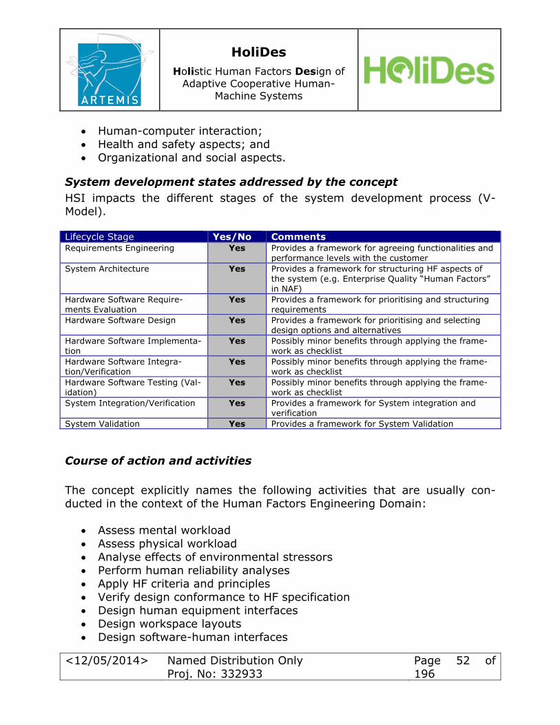
HoliDes
Holistic Human Factors Design of
Adaptive Cooperative Human-
Machine Systems
<12/05/2014> Named Distribution Only
Proj. No: 332933
Page 52 of
196
Human-computer interaction;
Health and safety aspects; and Organizational and social aspects.
System development states addressed by the concept
HSI impacts the different stages of the system development process (V-
Model). Lifecycle Stage Yes/No Comments Requirements Engineering Yes Provides a framework for agreeing functionalities and
performance levels with the customer
System Architecture Yes Provides a framework for structuring HF aspects of
the system (e.g. Enterprise Quality “Human Factors” in NAF)
Hardware Software Require-ments Evaluation
Yes Provides a framework for prioritising and structuring requirements
Hardware Software Design Yes Provides a framework for prioritising and selecting design options and alternatives
Hardware Software Implementa-tion
Yes Possibly minor benefits through applying the frame-work as checklist
Hardware Software Integra-tion/Verification
Yes Possibly minor benefits through applying the frame-work as checklist
Hardware Software Testing (Val-idation)
Yes Possibly minor benefits through applying the frame-work as checklist
System Integration/Verification Yes Provides a framework for System integration and verification
System Validation Yes Provides a framework for System Validation
Course of action and activities
The concept explicitly names the following activities that are usually con-
ducted in the context of the Human Factors Engineering Domain:
Assess mental workload
Assess physical workload
Analyse effects of environmental stressors
Perform human reliability analyses Apply HF criteria and principles
Verify design conformance to HF specification
Design human equipment interfaces
Design workspace layouts
Design software-human interfaces

HoliDes
Holistic Human Factors Design of
Adaptive Cooperative Human-
Machine Systems
<12/05/2014> Named Distribution Only
Proj. No: 332933
Page 53 of
196
Prepare/review drawings for conformance to HF specifications
NOTE: These activities are part of any good Human Factors practice.
NOTE: Depending on the product domain or user population, not all of the
criteria listed will be applied in detail.
NOTE: The descriptions of the other eight domains (other than Human Fac-tors Engineering) list activities more or less closely related to HF activities
(e.g. for the “Training”-Domain, the activity “Define instructional require-
ments” is listed). Those peripheral HF activities are not elaborated here.
Methods and outputs
The concept proposes the Human Factors Engineering activities listed in
Clause 2.1.5, but does not explicitly name methods for conducting them (e.g. methods for conducting the assessment of mental workload).
The concept does not specify a format for documenting or presenting the re-spective outcomes of specific HF activities.
The concept does not specify any tools used for conducting specific HF activi-ties.
STRENGTHS-WEAKNESSES Analysis
Strengths:
The concept is known to many customers (or forms even a basis for acquisition decisions) and can serve as a means for agreeing on re-
quirements The concept is very comprehensive (though not all HSI domains may
apply to a given product) and prevents aspects from being overseen or
being introduced at a late stage in product design
It supports the whole range of user interaction aspects (SW, HW, er-gonomics) and use cases (training, operation, maintenance, support)
It addresses safety and health-related issues, with the aim of prevent-
ing illnesses and recruitment/retention problems The nine HSI domains can serve as a checklist for the completeness of
the HF-RTP for AdCoS
Weaknesses:
Not all customers are familiar with it
In some instances only very few HSI domains may apply to a given product; in those cases simpler models may be more effective
HSI cannot be applied without some prior training
HoliDes
Holistic Human Factors Design of
Adaptive Cooperative Human-
Machine Systems
<12/05/2014> Named Distribution Only
Proj. No: 332933
Page 54 of
196
Even though HSI can be applied to just about any product, its military
background may appear offensive to some customers
4.1.2 Concept: NATO Human View
The following section describes the NATO Human View (HV) as a relevant HF
Integration Concept for the HoliDes AdCoS domain covered by Airbus. How-
ever, elements from other, less formalised HF concepts (i.e. experience, best practice, or internal style guides) will also be applied.
Reference
Human Systems Integration for Network Centric Warfare (2010). NATO
RTO Technical Report TR-HFM-155 NATO Human View Quick Start Guide
Application of the concept
The intention of the proposed approach is to define an architectural process
to be used in the construction of a generic AdCoS that could be used throughout the consortium.
NOTE: this model was initially designed for use within WP8, prior to deliver-
ing it to the consortium. However, the WP1 Task 1.2 requirement requires the model to be released to the consortium as it is being defined in parallel
with WP8. Therefore, this initial document has WP8 specific details and prod-ucts and our aim is to construct a consortium generic one.
The four diagrams are split in to two sections. The first (HoliDes-RTP-
Operational-Capabilities) defines the interaction of the Architectural products
(including Human Views) with the operational layer which includes the word
documents, spreadsheets etc. and requirements defined in DOORS. Note that WP8 anticipate the use of DOORS as it is the standard requirement product
used within Airbus Defence and Space.
The second diagram (HoliDes-RTP-AdCoS-Design) defines an example of how
the AdCoS could interact with the Operational Architecture, other tools and
the ‘experimentation equipment’. The diagram was designed for WP8 and
should be made more generic.
HoliDes
Holistic Human Factors Design of
Adaptive Cooperative Human-
Machine Systems
<12/05/2014> Named Distribution Only
Proj. No: 332933
Page 55 of
196
The subsequent section defines two logical data models. The first (SOS-
HoliDes-LDM) defines the interaction of the architectural products with the HoliDes specific Use Case definition. The second (SoS-HoliDes-Use-Case-
Interaction) defines the specific interaction from the Architectural products
and the HoliDes Use Case.
As Airbus Defence and Space have developed the Human Views from the
NATO definition, we are using the NATO Architectural Framework (NAF) defi-
nitions. However, the definitions are a slight mix between the frameworks. This does not cause a problem, as this document is an initial draft and defini-
tions can be re-defined when the toolset and frame have been decided.
Section 1 - Operational Capabilities
The definitions in the capability configuration “Other Work Packages” should
be clear and will not be expanded. The same can be said for Word, Excel and WP8 Requirements.

HoliDes
Holistic Human Factors Design of
Adaptive Cooperative Human-
Machine Systems
<12/05/2014> Named Distribution Only
Proj. No: 332933
Page 56 of
196
Work Package 8
<<Capability Configuration>>
Sparx - Enterprise Architect
<<System Resource>>
Other Work Packages
<<Capability Configuration>>
Architecture Views
<<System Resource>>
Functions
"Operational Concept - OV-1"
"System Resource Interaction - SV-1"
"Use Cases"
"System Resource Hierarchy SV-1"
"System Functions SV-4"
"Sequence Diagrams - OV-6c"
Human Views
<<System Resource>>
Functions
"HV-A Concepts"
"HV-C Tasks"
"HV-D Roles"
"HV-E Networks"
"HV-F Training"
"HV-B-Human Characteristics"
IBM - DOORS
<<System Resource>>
WP 8 Requirements
<<System Resource>>
Microsoft - Word
<<System Resource>>
Other tools OSLC Module
<<Software>>
WP Use Cases
<<System Resource>>
DOORS - OSLC Module
<<Software>>
Mircosoft -Excel
<<System Resource>>
EA OSLC Module
<<Software>>
Other Holides Tools
<<System Resource>>
Holides-RTP-Operational-
Capabilites (NSV-01 Resource
Interaction Spec.)
System Architect
Fri Mar 14, 2014 12:55
Comment
Work Packages 1 to 4
<<Capability Configuration>>
RTP Requirements Document
<<Capability Configuration>>
Work Packages 5,6,7 and 9
<<Capability Configuration>>
Architectural Data
Identified Requirements (manual)
Initial Capture (manual)
Requirement Transfer (manual)
Use Case Capture
Generic Requirements
WP 1 to 4 Tools
WP 5,6,7 and 9 Tools
Human Roles / Tasks etc
Operational / System / Service etc
WP Requirements Mapping
Other WP RTP Requirements
4-1: HoliDes-RTP-Operational-Capabilities [NSV-01 Resource Interac-
tion Spec.]

HoliDes
Holistic Human Factors Design of
Adaptive Cooperative Human-
Machine Systems
<12/05/2014> Named Distribution Only
Proj. No: 332933
Page 57 of
196
HF-issues covered by the concept
Human View covers HF-issues/aspects in the form of six Human Views HV-A to HV-F.
Human View Definition
HV-A Concepts The Concept view (HV-A) is a high-level representation of the human component of the enterprise architecture framework. Its purpose is to facilitate understanding of the human dimension in relation to operation-
al demands and system components. It serves as a single point of refer-ence and departure to depict how the human impacts performance (mis-sion success, survivability, supportability, and cost) and how the human is impacted by system design and operational context (e.g. personnel
availability, skill demands, training requirements, workload, and well-being).
HV-B Human Char-acteristics
The Human Characteristics view (HV-B) considers the physical character-istics and movement capabilities and limitations of an operator under various conditions.
HV-C Tasks The Tasks view (HV-C) describes human-specific activities (i.e., functions assigned to humans over a system’s entire life cycle). It also captures
how functions are decomposed into tasks. (The term task in this product refers to a piece of work that can be assigned).
HV-D Roles The Roles view (HV-D) describes the job functions that have been de-
fined for humans interacting with the system. A role therefore represents a job function defining specific behaviour within the context of an organi-zation, including the authority and responsibility conferred to the role,
and competencies required to do the job. The role structure can be mapped to the HV-C task decomposition to define organizational respon-sibilities, and relationships between roles can be defined to provide the
basis of the organizational structure.
HV-E Human Net-
work
The Human Network view (HV-E) captures human-to-human communica-tion patterns resulting from ad hoc or deliberate team formation, includ-
ing teams distributed across space and time.
HV-F Training The Training view (HV-F) is a detailed accounting of how training re-
quirements, strategy, and implementation impact the human. It illus-trates the educational level or training required to provide personnel with those tasks, skills, and knowledge necessary to meet job requirements.
Human View is, therefore, a very comprehensive framework, covering the whole range of Human Factors aspects including:
Human characteristics
Tasks and roles
Training
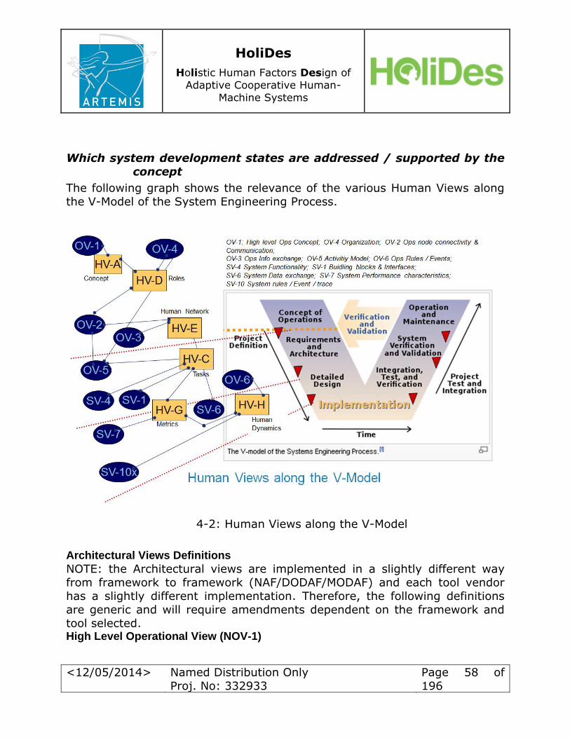
HoliDes
Holistic Human Factors Design of
Adaptive Cooperative Human-
Machine Systems
<12/05/2014> Named Distribution Only
Proj. No: 332933
Page 58 of
196
Which system development states are addressed / supported by the concept
The following graph shows the relevance of the various Human Views along
the V-Model of the System Engineering Process.
4-2: Human Views along the V-Model
Architectural Views Definitions
NOTE: the Architectural views are implemented in a slightly different way
from framework to framework (NAF/DODAF/MODAF) and each tool vendor
has a slightly different implementation. Therefore, the following definitions are generic and will require amendments dependent on the framework and
tool selected. High Level Operational View (NOV-1)
HoliDes
Holistic Human Factors Design of
Adaptive Cooperative Human-
Machine Systems
<12/05/2014> Named Distribution Only
Proj. No: 332933
Page 59 of
196
The NOV-1 describes a mission, class of mission, or scenario. It shows the
main operational concepts and interesting or unique aspects of operations. It describes the interactions between the subject architecture and its environ-
ment, and between the architecture and external systems. Operational Resource Flow (NOV-2)
The Operational Node Connectivity Specification (NOV-2) depicts Operational
Nodes with Needlines between those Nodes that indicate a need to exchange information. The NOV-2 may also show the location (geographic, or Platform)
of Operational Nodes, and may optionally be annotated to show flows of ma-
teriel or people between Nodes. The Operational Nodes shown in an NOV-2 Product may be internal to the Architecture, or external Nodes that com-
municate with those internal Nodes. Operational Relations Chart (NOV-4) - this may be replaced by Resource Hierarchy Diagram SV-1
The Organisational Relationships Chart illustrates the command structure or relationships (as opposed to relationships with respect to a business process
flow) among human roles, organisations, or organisation types that are the
key players in an Architecture. Event Trace (Sequence Diagram) (NOV-6c)
The Operational Event-Trace Description provides a time-ordered examina-
tion of the information exchanges between participating Operational Nodes as a result of a particular scenario. Each event-trace diagram will have an
accompanying description that defines the particular scenario or situation.
System Interaction (NSV-1) (System Resource Interaction)
NSV-1 identifies where relationships exist between systems – i.e. the key interfaces. Sub-system assemblies may be identified in NSV-1 to any level
(i.e. depth) of decomposition the architect sees fit. NSV-1 may also identify the System Nodes (e.g. Platforms) at which systems are deployed, and op-
tionally overlay Operational Nodes that utilise those systems. In many cases,
an operational node depicted in an NOV-2 product may well be the same as
the System Node that is shown in NSV-1. System Functionality (NSV-4)
The Systems Functionality Description documents system functional hierar-
chies and system functions, and the system data flows between them. WP Use Case
The standard Use Case template as defined for HoliDes
HoliDes
Holistic Human Factors Design of
Adaptive Cooperative Human-
Machine Systems
<12/05/2014> Named Distribution Only
Proj. No: 332933
Page 60 of
196
Course of action and activities
The initial Architectural products defined herein are based on one of the standards Architectural Frameworks used within Airbus Defence and Space
i.e. the NATO Architectural Framework (NAF) and are to be used within WP8.
The course of action required within WP1, will be to define if this Architectur-
al development, which is mandatory on all Defence contracts, can be used within the consortium to promote consistent modelling activities and re-use.
The architectural development is at the front end of the system development
process and integrates with the standards Use Case approach and require-ments management (DOORS).
Methods and outputs
The process follows standard architectural views defined in the NATO Archi-tectural Framework, with interpretation of said standard by each tool vendor.
The output will be in standard NATO Architectural Framework format, which is standard within Europe and mandatory for all NATO projects.
Tools
The NATO Architectural Framework has been implemented by many software
tool vendors, three of which have been defined: Enterprise Architect, System Architect and Rhapsody. These tools will be analysed in greater detail not
here, but in the next deliverable (D1.3). However, it is possible but not rec-ommended to define the views within Microsoft Office tools.
Section 2 HoliDes RTP AdCoS Design
The definitions in the capability configuration Other Work Packages should be
clear and will not be expanded.

HoliDes
Holistic Human Factors Design of
Adaptive Cooperative Human-
Machine Systems
<12/05/2014> Named Distribution Only
Proj. No: 332933
Page 61 of
196
Work Package 8
<<Capability Confi guration>>
AdCos Specific
<<System Resourc e>>
Other Work Pac kages
<<Capability Confi guration>>
System Hardware
<<Platform>>
ECLIPSE (WP8 T ool)
<<System Resourc e>>
WP Specifi c Design T ools
<<System Resourc e>>
Func tions
"WP Specific T ools"
Experimentation Equipment
<<Physic al Ass et>>
Func tions
Cameras
Phones
Radios
"V ideo Streams "
Operator Console(s)
<<Platform>>
Human S imulations
<<Software>>
Func tions
"Human Behaviour"
"Human Charac teristic s"
"Human Actions"
Adaptive Interventi ons
<<Software>>
Func tions
Interventions
Human Operators
<<Role T ype>>
Other tools OSLC Module
<<Software>>
ECLISE - OSLC Module ?
<<Software>>
Operational Arc hitecture
<<System Resourc e>>
Adcos Design (WP8 Control Room and Border Sec urity)
<<System Resourc e>>
Other Holides T ools
<<System Resourc e>>
Holides-RT P-Adcos-Des ign
(NSV-01 Resource
Interaction Spec.)
System Arc hitect
Fri Mar 14, 2014 12:55
Comment
Work Packages 1 to 4
<<Capability Confi guration>>
RT P Requirements Document
<<Capability Confi guration>>
Work Packages 5,6,7 and 9
<<Capability Confi guration>>
WP Des ign Data
Requirements
Interface Hardware / Software
Interface Hardware / Software
Operator Interface
Interface Hardware / Software
Human S imulation Design Data
Hman Simulati on Software Deis gn, Test and Intergrati on
Software Design Intergation and Test
Adati ve Software Des ign Data
HF Conc ept Data
Operator Interface
Generic Requirements
WP 1 to 4 T ool s
WP 5,6,7 and 9 Tools
Non OSLC Data - Adaptive s oftware
System Data
Human V iew Data
Operational Data
Other WP RTP Requi rements
Non OSLC Data - Human Simulations
ECLIPSE Data
4-3: HoliDes-RTP-AdCoS-Design [NSV-01 Resource Interaction Spec.]
Operational Architecture
HoliDes
Holistic Human Factors Design of
Adaptive Cooperative Human-
Machine Systems
<12/05/2014> Named Distribution Only
Proj. No: 332933
Page 62 of
196
See above.
ECLIPSE
WP8 specific Software tool, an OSLC interface maybe defined for inter-
action with other tools. If the tool defines software etc. that is used to build the AdCoS an interface or method of integration will need to de
defined.
WP Specific Design Tools
Any tool that is used in the construction of the AdCoS. If the tool de-fines software etc. that is used to build the AdCoS an interface or
method of integration will be required.
AdCoS Design
Defines the design of any specific AdCoS, with all its interfaces, in-put/outputs and integration.
Human Operators
All humans that will be involved in any WP experiment. This should in-
clude all humans required to run the experiment, and not just the op-erators (e.g. experiment designers, experiment controllers, experiment developers, observers, or Subject Matter Experts).
Experimentation Equipment
All equipment required to successfully run the experiment, together with any interfaces required.
Operator Consoles
Specific real or simulated operator consoles for each WP. For WP8 this
will mean operator control consoles, other WP will require a variety of
WP specific equipment.
System Hardware
Any hardware that is required to execute any WP specific piece of soft-
ware e.g. simulation or adaptive, together with any interfaces required.
Adaptive Interventions
Any software adaptive intervention developed for any defined experi-
ment, together with any interfaces required.

HoliDes
Holistic Human Factors Design of
Adaptive Cooperative Human-
Machine Systems
<12/05/2014> Named Distribution Only
Proj. No: 332933
Page 63 of
196
Human Simulations
Any software human simulation, together with any interfaces required.
OSLC
We need to define how we are going to use OSLC from a consortium
perspective and then from the individual WP, as WP8 indicates we will
look at developing a Link between Enterprise Architect and DOORS.
SoS-HoliDes-LDM Information Model
The following logical data models are generic and will require updating when
we decide on the products we are going to produce. The Logical Data Model will define the overall architectural products and their data interfaces, in
terms of frameworks and tools.
Logical Data Model (SoS-HoliDes-LDM) for the interaction for a generic archi-tectural model for use within the HoliDes consortium.
HoliDes
Holistic Human Factors Design of
Adaptive Cooperative Human-
Machine Systems
<12/05/2014> Named Distribution Only
Proj. No: 332933
Page 64 of
196
SoS-Holides-Use-Case
NameIdentifierCategoryDescriptionPre-Condition"Success-End Condition""Trigger Event""Minimal Guarentee""Success Steps""Roles / Actors"FeatureEnvironment"Scenario Extensions""Scenario Picture""Software Resources"Agents"Alternate Flows"
SoS-HV-A Concept
SoS-SV-1-SystemsInterface Description
SoS-OV-1-High Level OperationalGraphic
SoS-HV-D Roles
SoS-HV-C-Tasks
SoS-OV-4-OperationalRelations Chart
SoS-OV-5a-Operational ActivityDecomposition Tree
SoS-SV-4-SystemsFunctionality Description
SoS-HV-E-Human Networks
SoS-OV-2-OperationalResource FlowDescription
SoS-HV-F Training
SoS-OV-6c-EventTrace Description
SoS-HV-B6 HumanChracteristics
SoS-Holides-LDM (NOV-07 Information Model Subject Area)System Architect
Thu Dec 12, 2013 11:23Comment
Initial Holides Logical Data Model - Architecture Viewpoints
Yellow - Human ViewsGreen - System Views
Blue - Operational Views
Personnel Constraints
Limits
Operational Picture
Human Interaction Graphic
Physical Assets / Software
Sceanrio to Sequence Diagram
Roles to Roles
Node to Node
Triggers
Roles / Units / Entities to Actors
Use Case / Human Process
Roles to Actors
Roles/Posts/Organisations
Requirements
Key Players / Interactions
Tasks to Operational Activitives
Roles / Units to Roles / Units
Roles / Units to Roles / Units
Roles to Roles
Recources /Organisations
System / Functional Requirements
Overlaid as Backbone
Realised Resources
Roles / Units to Roles / Units
Elaborate Capabilities
Function to Function
Resources carry Functions
Posts/Roles to Roles
Training Needs
Roles to Roles
Tasks to Roles
Roles to Roles
Human representation
4-4: SoS-HoliDes-LDM [NOV-07 Information Model]
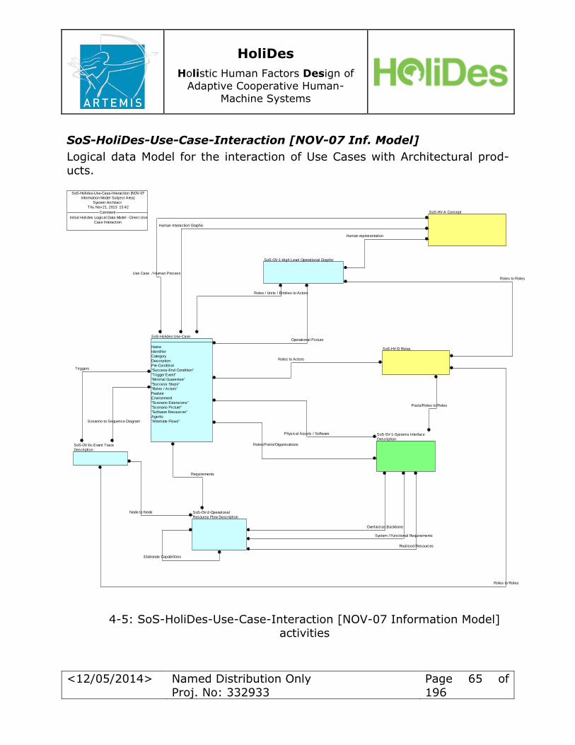
HoliDes
Holistic Human Factors Design of
Adaptive Cooperative Human-
Machine Systems
<12/05/2014> Named Distribution Only
Proj. No: 332933
Page 65 of
196
SoS-HoliDes-Use-Case-Interaction [NOV-07 Inf. Model]
Logical data Model for the interaction of Use Cases with Architectural prod-ucts.
SoS-Holides-Use-Case
Name
Identifier
Category
Description
Pre-Condition
"Success-End Condition"
"Trigger Event"
"Minimal Guarentee"
"Success Steps"
"Roles / Actors"
Feature
Environment
"Scenario Extensions"
"Scenario Picture"
"Software Resources"
Agents
"Alternate Flows"
SoS-HV-A Concept
SoS-SV-1-Systems Interface
Description
SoS-OV-2-Operational
Resource Flow Description
SoS-OV-1-High Level Operational Graphic
SoS-HV-D Roles
SoS-OV-6c-Event Trace
Description
SoS-Holides-Use-Case-Interaction (NOV-07
Information Model Subject Area)
System Architect
Thu Nov 21, 2013 15:42
Comment
Initial Holides Logical Data Model - Direct Use
Case Interaction
Physical Assets / Software
Human Interaction Graphic
Operational Picture
Human representation
Roles to Roles
Posts/Roles to Roles
Elaborate Capabilities
Realised Resources
Overlaid as Backbone
System / Functional Requirements
Requirements
Roles/Posts/Organisations
Roles to Actors
Use Case / Human Process
Roles / Units / Entities to Actors
Triggers
Node to Node
Roles to Roles
Sceanrio to Sequence Diagram
4-5: SoS-HoliDes-Use-Case-Interaction [NOV-07 Information Model]
activities
HoliDes
Holistic Human Factors Design of
Adaptive Cooperative Human-
Machine Systems
<12/05/2014> Named Distribution Only
Proj. No: 332933
Page 66 of
196
STRENGTHS-WEAKNESSES Analysis
Strengths: Based on international NATO standards - NATO Architecture Frame-
works (NAF)
Human Views based on NATO Human View Technical Report [3]
The standards have been extensively used with Airbus Defence and Space
The ability to produce a common Logical Data model that can be used
within all HF type projects
To provide a generic HF model that not only defines Humans in terms of their interaction with machines, system, software etc. but includes
Human to Human behaviour, Human networks etc. , which will probably be a first time this has been accomplished
Weaknesses: This initial model was constructed to be used within WP8, it will need
to be reviewed to ascertain if it capable of support the other Work Packages
The standard is based on Military standards, therefore, a review needs to be performed if any modification can be made to provide a generic
HF model for use within the consortium.
4.2 HF and Safety Regulations in Control Rooms Domain
4.2.1 Control Centre Design Standard
Introduction
ISO 11064 is concerned with an International Standard called “Ergonomic
design for control centers” and it consists of seven different parts. Part 1 is
the most commonly used in the Control Room domain. Part two contains some design principles. Part three contains a control room layout procedure.
Part four contains a procedure for an efficient workstation design. Part five
has to do with the checklist procedure for the control rooms. Part six con-tains a control room environmental design which takes into account the
weight of sensation/perception source of stimulation. Part seven contains a
description how to integrate validation and verification processes. The indi-
vidual 7 parts of the Standard are reviewed in the following sections.

HoliDes
Holistic Human Factors Design of
Adaptive Cooperative Human-
Machine Systems
<12/05/2014> Named Distribution Only
Proj. No: 332933
Page 67 of
196
Reference
ISO 11064 Control Centre Design Standard: ISO 11064-1: Principles for the design of control centres; DIN
Deutsches Institut für Normung e.V.; 2001
ISO 11064-2: Principles for the arrangement of control suites; DIN
Deutsches Institut für Normung e.V.; 2001 ISO 11064-3: Control room layout; DIN Deutsches Institut für Nor-
mung e.V.; 2000
ISO 11064-4: Layout and dimensions of workstations; DIN Deutsches Institut für Normung e.V.; 2004
ISO 11064-5: Displays and controls; DIN Deutsches Institut für Nor-
mung e.V.; 2008 ISO 11064-5: Environmental requirements for control centres; DIN
Deutsches Institut für Normung e.V.; 2005 ISO 11064-7: Principles for the evaluation of control centres; DIN
Deutsches Institut für Normung e.V.; 2006 A case study of ISO 11064 in Control Centre Design in the Norvegian
Petroleum Industry, Aas A.L, Skramstad T. (2010), Applied Ergonomics
62-70.
Part 1: Principles for the design of control centres
Application of the regulation Domain: control rooms System: control centres as a whole
HF issues Taking into account the HF activities described in this standard, ISO
11064 addresses every HF-issue classified by Eurocontrol very briefly:
1. Working environment (1.2.1 – Design)
2. Organisation and staffing (2.1.4 – Communication and consulta-tion, 2.3.1 – Physiological factors, 2.3.2 – Psychological factors)
3. Training and development (3.4 – Training planning)
4. Procedures, roles and responsibilities (4.1.1 – Prescribed working
methods and individual working practices, 4.4 – Working Method)
5. Teams and communication (5.1 – Team interaction, 5.2 – Com-munications)
6. Human in system (6.1.6 – Allocation of function between human
and machine, 6.2.1 – System Reliability)
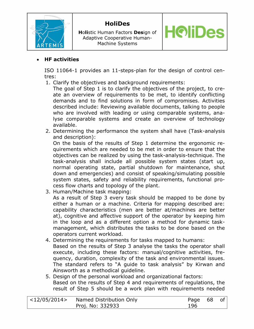
HoliDes
Holistic Human Factors Design of
Adaptive Cooperative Human-
Machine Systems
<12/05/2014> Named Distribution Only
Proj. No: 332933
Page 68 of
196
HF activities
ISO 11064-1 provides an 11-steps-plan for the design of control cen-tres:
1. Clarify the objectives and background requirements:
The goal of Step 1 is to clarify the objectives of the project, to cre-
ate an overview of requirements to be met, to identify conflicting demands and to find solutions in form of compromises. Activities
described include: Reviewing available documents, talking to people
who are involved with leading or using comparable systems, ana-lyse comparable systems and create an overview of technology available.
2. Determining the performance the system shall have (Task-analysis and description):
On the basis of the results of Step 1 determine the ergonomic re-quirements which are needed to be met in order to ensure that the
objectives can be realized by using the task-analysis-technique. The task-analysis shall include all possible system states (start up, normal operating state, partial shutdown for maintenance, shut
down and emergencies) and consist of speaking/simulating possible
system states, safety and reliability requirements, functional pro-cess flow charts and topology of the plant.
3. Human/Machine task mapping: As a result of Step 3 every task should be mapped to be done by either a human or a machine. Criteria for mapping described are:
capability characteristics (men are better at/machines are better at), cognitive and affective support of the operator by keeping him
in the loop and as a different option a method for dynamic task-
management, which distributes the tasks to be done based on the
operators current workload. 4. Determining the requirements for tasks mapped to humans:
Based on the results of Step 3 analyse the tasks the operator shall
execute, including these factors: manual/cognitive activities, fre-
quency, duration, complexity of the task and environmental issues.
The standard refers to “A guide to task analysis” by Kirwan and Ainsworth as a methodical guideline.
5. Design of the personal workload and organizational factors:
Based on the results of Step 4 and requirements of regulations, the
result of Step 5 should be a work plan with requirements needed
HoliDes
Holistic Human Factors Design of
Adaptive Cooperative Human-
Machine Systems
<12/05/2014> Named Distribution Only
Proj. No: 332933
Page 69 of
196
for communication between operators, trainings, directives as well
as information about the process. Methods described are: defining a preliminary work plan and tasks that every operator has to do, by
taking results of Step 4 and regulations into account.
6. Verification and validation of the results of steps 3, 4 and 5:
Evaluation of function-/task-management, task requirements, tasks every operator has to do, work plan. Possible methods for evalua-
tion described are regarding critical incidents or a computer simula-
tion. The final step is to get the confirmation of the owner. 7. First conceptual design of the control centre:
Defining the design principles is the next step described. After de-
fining them, they shall be compared to user requirements (results of Step 6) and regulations in effect. Step 7 should lead to several
proposed solutions. 8. Review and approval of the conceptual design:
Methods described are talking about or playing through the pro-posed designs, simulation of necessary team-working aspects, vis-ualisations through animations via PC, auditing of the regulations in
effect.
9. Detailed design: This shall include adjoining (ISO 11064-2) and control (ISO 11064-
3) rooms, workstations, displays, actuators, environmental design – each part is described separately. Methods proposed are feasibility studies taking into account common systems for realizing the pro-
ject, prototyping and creating style guidelines. 10. Review and approval of the detailed design:
Validation of the detailed design has to be integrated and iterative. The results have to deliver information, which the designer can use
for correction/adjustment of his design. Safety, decrease of error margin, ergonomic design, environmental factors and job satisfac-
tion are the most important issues for reviewing.
11. Acquisition of operational experiences after putting the control
room into service:
It is important to record ergonomic insufficiencies as help for simi-lar projects to come. ISO 11064-1 proposes field studies, inter-
views, task-analysis and surveys as possible methods.

HoliDes
Holistic Human Factors Design of
Adaptive Cooperative Human-
Machine Systems
<12/05/2014> Named Distribution Only
Proj. No: 332933
Page 70 of
196
HF workflow
ISO 11064-1 is a workflow in itself and it is difficult to map it to the V-Model, besides V-Model is about software and this ISO about building a control cen-
tre. If one would try to map the two workflows it might look like this:
V-Model ISO 11064-1
(1) Step 1 & 2
(2) Step 3
(4) Step 4, 5, 6 & 7
(5) Step 9
(7) Step 8 & 10
(9) Step 11
Additional relevant information and notes
ISO 11064-1 elaborates nine basic HF/ergonomic-design principles, which need to be addressed while building a control room:
1. Human-centred-Design: Human physiological and psychological limits always need to be kept in mind while designing a control
room.
2. Integration of ergonomics in the technical practice: Both, the technical and ergonomic, points of view need to be included while realising a project.
3. Work iteratively: Even changing a small part can change the whole man-machine system. Therefore there has to be a test and possi-
ble correction after each change of the system.
4. Situation analysis: Analyse comparable situations and take into account ergonomic lessons learnt.
5. Task analysis: Every possible task (including start up, normal op-
erating state, partial shutdown, shut down and emergencies) needs to be understood and therefore be analysed (ISO 6385).
6. Every system has to be fault-tolerant.
7. Include experienced users in the designing process, since their ex-
periences are often not documented. 8. Interdisciplinary workgroups: Groups consistent of e.g. process
engineers, ergonomics, architects and industrial designers should
supervise and control the whole process of building a control room to ensure, that every discipline involved equally.
9. The whole ergonomic design needs to be documented.
HoliDes
Holistic Human Factors Design of
Adaptive Cooperative Human-
Machine Systems
<12/05/2014> Named Distribution Only
Proj. No: 332933
Page 71 of
196
General evaluation and summary
ISO 11064-1 is a detailed design workflow for control rooms beginning with analysing the requirements of the control room to be build and
ending with evaluating the built system. It proposes a lot of general
methods and activities but nevertheless lacks precise information about
what has to be done and how to it should be done exactly. The stand-ard is a guideline but one needs to have a lot of background infor-
mation or experience to follow it.
Part 2: Principles for the arrangement of control suites
Application of the regulation
Domain: control rooms System: control- and adjoining room
HF issues
o Keep transport routes as short as possible; choose appropriate
doors; etc. (1.1 Work place layout)
o Minimize the effects of disturbing sources like noise; reflecting
lights; heat; vibrations etc. (1.3 Physical environment) o If possible optimize the alignment of rooms for communication be-
tween operators (5.2 Communications)
HF activities
In ISO 11064-2 the only activities described are methods for verification and validation of a finished layout. Validating the ways of transportation and
communication can be done by analysing the connections needed. Other
techniques for evaluating the design proposed are “walk through and talk
through techniques”, “virtual reality techniques” and ISO 11064-7.
HF workflow
ISO 11064-2 proposes a workflow for designing the layout of a control room
with adjoining rooms. This workflow is based on the process described in ISO 11064-1 and starts after Step 8 (Review and approval of the conceptual de-
sign).

HoliDes
Holistic Human Factors Design of
Adaptive Cooperative Human-
Machine Systems
<12/05/2014> Named Distribution Only
Proj. No: 332933
Page 72 of
196
General evaluation and summary
ISO 11064-2 addresses just a view, but very specific HF issues. The described activities are meant for validation but might also be useful
from the start, if used correctly. The standard proposes a workflow
filled with general activities and lists a lot of detailed aspects to be con-
sidered. It lacks precise information about what to do exactly.
Part 3: Control room layout
Application of the regulation
Domain: control rooms System: control room
HF issues
All issues described in ISO 11064-3 can be mapped to Eurocontrols HF-category 1: Working environment. Topics mentioned are:
o Ceiling height, required space per workplace, door position, required
space for walking/cleaning, workplace setting, minimization of pos-
sible barriers (1.1 Work place layout) o Line-of-sight, size of placement areas for operators (1.2.1 Operator
working position design) o Window arrangement (1.3.2 Physical environment lighting)
HF activities
ISO 11064-3 lists a lot of general recommendations based on experi-
enced data e.g. the required space per workplace is about 9 to 15 m².
It gives formulas for calculating the line-of-sight, the required space for
walking/cleaning and sets ground rules for the arrangement of win-dows (no windows directly in front or behind the operators).
HF workflow
Based on the results of Step 8 (Review and approval of the conceptual design) of ISO 11064-1 described this standard provides another work-
flow, which develops several drafts of a functional control room layout
step by step. Every draft shall take into account the rules and regula-
HoliDes
Holistic Human Factors Design of
Adaptive Cooperative Human-
Machine Systems
<12/05/2014> Named Distribution Only
Proj. No: 332933
Page 73 of
196
tions described. The different drafts shall be tested in a realistic simu-
lation. Afterwards one final draft has to be chosen.
General evaluation and summary
ISO 11063-3 gives a detailed overview about ergonomic and human
factors issues that need to be addressed while designing a control
room. It provides not only a workflow but also some very exact infor-mation about how to resolve some of the issues described.
Part 4: Layout and dimensions of workstations
Application of the regulation Domain: control rooms
System: workstations as a whole
HF issues
o Workstation layout: size; accessibility of the controls based on per-
sonal factors; working posture; maximum amount of displays to be supervised by an operator (1.2.1 Operator working position Design;
2.3 Personal Factors) o Visual tasks: Line-of-sight; minimum size of information provided
on displays; minimum/maximum distance between the eye and dis-plays
o Aural tasks: informational and alarm signals (6.1.4 Alert signals) The standard gives a reference to ISO 11064-5 for the choosing of
suitable actuators and controls.
Accessibility of the controls, a good line-of-sight to every display and a
healthy working posture can be realized by using adjustable compo-nents.
Workstations have to be suitable for the 5 to 95 percentile of possible
operators. Appendix A provides rules and examples of how to set multiple displays
for optimized usage.
HF workflow
ISO 11064-4 provides a repetitive workflow consisting of six steps
based on Step 8 (Review and approval of the conceptual design) de-

HoliDes
Holistic Human Factors Design of
Adaptive Cooperative Human-
Machine Systems
<12/05/2014> Named Distribution Only
Proj. No: 332933
Page 74 of
196
scribed in (HF activities of ISO 11064-1). To sum up: After Step 8 of
ISO 11064-1 there should be a first layout of the control rooms and a detailed work plan for every operator and workstation needed. The
steps of ISO 11064-4 are:
1. Determine which informational and interventional systems will be
needed for every workstation. 2. Determine which equipment (displays, communication facilities, ac-
tuators, etc.) will be needed.
3. Determine the expected postures while being at work (sitting, standing) and collect anthropometric data of future users (ethnic
group, male/female, disabled).
4. Design the workstation in top- and side view. Check on working postures, free line-of-sight to all sources of information needed,
possibility to interact with every actuator, availability of enough space for documents and telecommunication systems needed. Also
take cleaning into account. 5. Verify and validate the design by involving the future operator. In-
vestigate the possibility of future maintenance. If something needs
to be changed, start again at Step 2 or 4.
6. Document the design including limitations, alternative considera-tions and recommendations for future projects.
Additional information
Appendix B provides a checklist that can be used to review a finished design for missed issues which needed to be addressed.
General evaluation and summary
ISO 11064-4 is a complete overview about how to design a workstation ergonomically. It addresses the major HF issues and describes possible
ways to resolve most of them. Aural tasks and alarm signals are only
mentioned very briefly.
Part 5: Displays and controls
Application of the regulation
Domain: control rooms
System: displays and controls
HoliDes
Holistic Human Factors Design of
Adaptive Cooperative Human-
Machine Systems
<12/05/2014> Named Distribution Only
Proj. No: 332933
Page 75 of
196
HF issues
ISO 11064-5 lists 24 HF issues relevant for humans in systems. (6. Human in system):
1. Humans need to be in charge while working in a man-machine sys-
tem.
2. Systems need to provide all information needed so men can exe-cute their tasks.
3. Human-system interfaces have to support men in efficiently and ef-
fectively doing their jobs. 4. Human capabilities need to be considered while designing human-
system interfaces.
5. Ergonomic ground rules need to be considered while designing hu-man-system interfaces.
6. Operators need to be provided with all information needed to be able to create a mental model of the process they are supervising.
7. The created task should promote and offer both a satisfying and challenging work environment.
8. The requirements of the operators’ short-term memory should not
exceed known limits.
9. Information provided has to be easy and clearly understandable when observed by trained operators.
10. Items that need to be distinguished from each other need to be provided separately.
11. Only actual information shall be provided. If it isn’t possible to pro-
vide accurate information that fact shall be highlighted by the sys-tem.
12. Alerts need to fit to their importance for the operator or safety of
the system.
13. Information needs to be provided consistently throughout the whole system.
14. Information needs to be provided readably, clearly, precisely, con-
sistently, observable, understandingly and discriminable.
15. Items to be controlled by the operator have to be visible at all
times. 16. Human-system interaction should be configured as easy as possi-
ble.
17. The system should support the operator while he is giving input.
HoliDes
Holistic Human Factors Design of
Adaptive Cooperative Human-
Machine Systems
<12/05/2014> Named Distribution Only
Proj. No: 332933
Page 76 of
196
18. The system shall use available data and therefore minimize input
needed from the operator. 19. Requirements caused by frequently occurring situations shall be
minimized by the systems automation.
20. Operators need to be provided with feedback at all times.
21. The systems response time needs to be suitable for the task being executed.
22. High priority alerts need to catch the attention of the operator at all
times. 23. The system has to be tolerant for mistakes being made by the op-
erator and if possible reduce their impact.
24. Dialogues have to be structured in groups with a clear beginning, middle and end.
Each item is presented with a couple of central questions for evaluating a man-machine system.
In a later part of the standard the issue of alarm signals (general re-quirements, structuring, presentation, interaction and administration, documentation) is specially addressed. (6.1.4 Alert signals)
HF activities
Appendix A gives a detailed overview about possible arrangements to treat the issues described. The topics are:
o How to display information? o Configuration of human-system interaction o The design of displays
o Communication systems o Video systems and presentation of graphics
o Alert systems
Every topic comes with a detailed workflow based on the general pro-
cess described in ISO 11064-1 and a lot of general data based on les-sons-learned from former projects.
HF workflow
Based on the results of ISO 11064-1 this standard provides another
repetitive workflow of 7 steps for the design of human-system interfac-
es (displays and controls):
1. Analyse the transfer of information between operator and system needed for an accurate process.

HoliDes
Holistic Human Factors Design of
Adaptive Cooperative Human-
Machine Systems
<12/05/2014> Named Distribution Only
Proj. No: 332933
Page 77 of
196
2. Development of an overall framework for the design of the human-
system interface. Result is a list of main topics to be considered. 3. Development of a first concept taking into account the results of
Step 2.
4. Build a prototype and test it.
5. Based on the experiences of Step 4 develop the final framework. Mentioned topics should be: display of information, control actua-
tors, prompt, menus and dialogues, navigation, alert management,
standards. 6. Detailed designing of the human-machine interface by an ergonom-
ic expert. Every decision made needs to be documented.
7. Verification and validation based on ISO 11064-7.
General evaluation and summary
ISO 11064-5 is a very detailed standard addressing nearly every HF is-sue possible for human-system interactions. It contains several work-
flows, general data and checklists useful for evaluating.
Part 6: Environmental requirements for control centres
Application of the regulation
Domain: control rooms System: physical environment auf workstations
HF issues
ISO 11064-6 addresses environmental issues that can have a huge im-
pact on the operators’ capability to work. Issues described are:
o Thermic conditions (Temperature & Humidity) o Air quality
o Lighting
o Noise o Vibrations
o Interior design
HF activities
ISO 11064-6 defines nine ground rules, which need to be followed
while designing the environment of control room workstations:
HoliDes
Holistic Human Factors Design of
Adaptive Cooperative Human-
Machine Systems
<12/05/2014> Named Distribution Only
Proj. No: 332933
Page 78 of
196
1. The tasks to be executed by the operator and his personal comfort
need to be the main focus. 2. To optimise the operator’s performance and comfort he should be
able to set different lightning and temperature levels.
3. If there is a conflict between different environmental issues a bal-
ance needs to be found. 4. Factors that give information for controlling need to be recognized
while designing control rooms.
5. Environmental issues work interactively and need to be considered holistically.
6. The environmental factors should be used to compensate for issues
of shift-work, e.g. rise of temperature in the early morning. 7. Changes that might be made in the future need to be considered.
(e.g. equipment, workstations or organizational factors) 8. Environmental issues need to be integrated in the process of ISO
11064-1. 9. To achieve a balance between building, equipment and environ-
mental issues it is obligatory to use a repetitive, and multi-
disciplinary workflow.
HF workflow
Based on ISO 11064-1 this standard provides the repetitive workflow
mentioned in ground rule 9, which should be used when thinking about environmental issues.
Apart from that ISO 11064-6 also provides detailed workflows for the issues of temperature, lightning and noise.
Additional relevant information and notes
Appendix A provides some exact requirements (like temperatures, lu-
minosity etc.) based on several engineering standards.
General evaluation and summary
This standard is a good collection of the environmental issues that
might have an impact on ergonomics and need to be addressed while
designing a control room, but mainly lists its requirements. For each is-
sue mentioned very briefly, there are more specific engineering stand-
HoliDes
Holistic Human Factors Design of
Adaptive Cooperative Human-
Machine Systems
<12/05/2014> Named Distribution Only
Proj. No: 332933
Page 79 of
196
ards available, which might include activities to resolve the issues de-
scribed.
Part 7: Principles for the evaluation of control centres
Application of the regulation
Domain: control rooms System: evaluation of control centres
HF issues
Verification/validation of HF issues addressed in ISO 11064 part 1-6
HF activities
A verification and validation plan shall be drawn at the beginning of each project. The plan shall contain the HF issues; a timeline for vali-
dation of the activities being used; criteria, techniques and means for evaluating; etc.
Appendix C lists several possible methods for validation and gives a short explanation how to use them:
o Pen and paper methods: Ergonomic checklist
Examination of lessons-learnt (in comparable systems) Task analysis
Logical tree diagram o Observation methods:
Walk/talk through techniques
Cycle analysis
Performance tracking o Expert opinion methods:
Delphi technique
Nominal group technique Pairwise comparison technique
Estimation of proportion technique
o Experimental methods
o Measuring of physical dimensions
HoliDes
Holistic Human Factors Design of
Adaptive Cooperative Human-
Machine Systems
<12/05/2014> Named Distribution Only
Proj. No: 332933
Page 80 of
196
HF workflow
Throughout the whole process described in ISO 11064 it needs to be verified and validated, starting as soon as possible. Based on the work-
flow of ISO 11064-1 this part 7 defines five stages, three (analytical,
conceptual, detailed design stage) of which need to be verified and val-
idated. The workflow described is repetitive: Stages with inacceptable results need to be revised. Stage E is validation while running the con-
trol centre. That might offer some lessons-learnt that could be used in
future projects.
Additional relevant information and notes
Appendix A contains a checklist which can be used to check if the
workgroup for verification and validation is set up properly and gets all the information needed to do its job.
General evaluation and summary
ISO 11064-7 provides a short overview about the most important eval-
uation and verification techniques; a workflow which shall be consid-ered when thinking about how to integrate evaluation in the engineer-
ing life cycle and some information about appropriate quality factors which need to be considered while evaluating a system.
Assessment of the industrial application of the ISO 11064 Control
Centre Design Standard
The research of Aas & Skramstad (2010), reviewed here, was a case study
aimed at assessing the industrial application of the standard. The study was
conducted in the Norwegian Petroleum Sector. It applies at different dimen-
sions and specifically it applies to ergonomics across the cognitive, the physi-cal and the social ergonomics. These three dimensions are closely related
each other. The strength of the ISO 11064 is that it is flexible and adaptive.
According to the authors, the paper, as a case study, analyses the case of Norwegian petroleum with respect to part 1 of the ISO 11064. The authors
describes the main five steps in the ergonomic approach to the system de-
sign process:

HoliDes
Holistic Human Factors Design of
Adaptive Cooperative Human-
Machine Systems
<12/05/2014> Named Distribution Only
Proj. No: 332933
Page 81 of
196
a. the first step aims at clarifying the constraints through which the de-
sign process should move starting, for example, from existing situa-tions;
b. the second step involves the analysis of the requirements related to
the functions and performance of the control room in order to get a
preliminary evaluation; c. the third step is devoted to the description of the initial structure of
the rooms in terms of displays, tools and interfaces which are evalu-
ated, as necessary; d. the fourth step consistsof a specification of the step number 3 adding,
for example, contents and operational interfaces;
e. the fifth step consists of a post-commissioning review process to point out successes and shortcomings for the future actions.
The main objective of the study was to analyse the application of the ISO 11064. The method was in two parts. In the first part, a series of open-
ended, semi-structured interviews were made for professionals in the oil sec-tor regarding the application of the ISO 11064. The sample was selected from the Human Factors in Control forum. Two years later, the second part
took place. An on-line survey on a seven level Likert scale was used to follow
up the results of the first part, which involved both participants of the previ-ous forum as well as new participants. The recruitment resulted in 29 partici-
pants who actually used ISO 11064 in their professional experience. The main analyses of the interviews evidenced that around the 65% of the inter-viewees emphasised the need to introduce adaptivity features to the stand-
ard in order to take into account the different contexts it should be applied to. In addition, half of the participants suggested to include Human Factors
early in a project. Most of the sample evaluated the standard in a range from sufficient to good (around 80%). None of the participants found it excellent,
poor or very poor. The data has been clearly discussed by the authors who pointed out the strengths and weaknesses of the study. The first point was
about the application of standards for specific vs. general domains; how
much a standard should be normative in nature and how much it should be
goal based. A goal based approach should satisfy the need of adaptability of
the standard to specific contextual situations. However, the risk should be a lack of generalisation, which is implicit in a standard. Another main point of
the research concerns the methodological tools through which data for
validation should be built. The authors, for the second part of the study, used
a seven point Likert scale for the answers. The use of a Likert scale gives rise
to many intermediate answers. No one used answers as excellent, poor, and

HoliDes
Holistic Human Factors Design of
Adaptive Cooperative Human-
Machine Systems
<12/05/2014> Named Distribution Only
Proj. No: 332933
Page 82 of
196
very poor. This must be taken into consideration when studying a baseline
for HF studies. Finally, the paper had few participants and, as a consequence, it had some problems to generalise the results from the
sample to the populations. The statistical analyses that could have been
applied are at a nominal/ordinal scale given the high number of qualitative
answers concerning the interview part. This issue must be taken into account for any research in standard domain.
The paper has the merit to analyse the complex domain of standards by
stressing factors neglected in previous researches.
4.2.2 Design criteria standard – Human engineering
Reference
MIL-STD-1472G: Design criteria standard – Human engineering; U.S. De-partment Of Defence; 2012
Application of the regulation
Domain: military systems, equipment and facilities
System: control centres as a whole
HF issues
MIL-STD-1472G provides a vast number of requirements and recommenda-tions, most of which are useful while designing a control room. Issues ana-
lysed are: Controls: Computer controls, display integration (6.1.1 Input devices)
Visual displays: Content, hardware (6.1.2 Output devices) Speech and audio systems: Displays, speech recognition (6.1.1 Input
devices, 6.1.2 Output devices)
Labelling (1.1.1 Support equipment and furniture required)
Environment: Illuminance, noise, vibration (1.3 Physical environment) Warnings: Display, visual displays, auditory displays, general work-
space hazards, electrical, mechanical, fluid, toxic and radiation haz-
ards, fire, dust, safety barriers (6.1.4 Alert signals) Physical accommodation: Target population, anthropometric design
(2.3.1 Physiological factors)
Maintenance accessibility (1.1 Work place layout)
Workspace design: Workspace provision, workstation design, Illumina-
tion (1.2.1 Operator working position design)
HoliDes
Holistic Human Factors Design of
Adaptive Cooperative Human-
Machine Systems
<12/05/2014> Named Distribution Only
Proj. No: 332933
Page 83 of
196
Physical environment design: Stairs, passageways (1.1 Work place
layout) Virtual environments, remotely handled systems, automated systems,
telepresence and teleoperations (6.2.2 Automation & new technology)
HF activities
MIL-STD-1472G lists very precise information about how issues mentioned shall be treated (e.g. maximum lux/m² for illuminance or how to design an
ergonomic workstation). It focusses on the requirements and recommenda-tions and lacks methods and tools which might be useful for someone who
wants to meet the requirements/recommendations described.
HF workflow
Since MIL-STD-1472 provides a list of requirements and recommendations it might be mapped to Stage 3 and 4 of the V-Model.
Additional information
MIL-STD-1472 has not had a thorough technical review since the late 1980s.
MIL-STD-1472D was promulgated in March 1989, and hence addressed the level of technology that existed through 1988 or possibly 1987. The “E” revi-
sion, promulgated in 1996, was mostly cosmetic; the text was changed to a non-proportional font in order to reduce white space. The “F” revision, prom-
ulgated in 1999, consisted mainly of moving the anthropometric data from MIL-STD-1472 to MIL-HDBK-759, but little else. As a result, requirements
and design criteria contained in previous versions of MIL-STD-1472 may no longer be applicable to today’s technology. The operational benefits of
emerging technologies may be limited due to the out-of-date design criteria.
Tomorrow’s systems will depend on greater cognitive processing on the part
of the human operator, maintainer, and support personnel. Portable or wear-able computers are likely to be commonplace. New display concepts such as
virtual reality, haptic (touch sensing), and three-dimensional are receiving a
great deal of interest, as are voice, pointing, gesture, and eye-blink control systems. Technology, if misapplied, will impose human performance re-
quirements that cannot be satisfied. Many technologies are evolving rapidly;
the human is not. The benefits of new technologies may not be realized if
one fails to consider human capabilities and limitations.

HoliDes
Holistic Human Factors Design of
Adaptive Cooperative Human-
Machine Systems
<12/05/2014> Named Distribution Only
Proj. No: 332933
Page 84 of
196
The changes made in the “G” revision over the previous version are sub-
stantial. The organizational structure of the standard was revamped to group similar material in the same section of the document. Obsolete provisions
(e.g., reference to dot-matrix printers) were deleted, out-of-date provisions
were updated to reflect the latest research, and new provisions were added
to address emerging technologies. See 6.4 for a summary of changes to the present “G” revision. (Original text from MIL-STD-1472: foreword)
General evaluation and summary
This standard is a document of 381 pages which provides a very detailed
view about the most important HF issues. To list and explain every topic mentioned would go beyond the scope of this summary. The standard pro-
vides neither methods/tools nor a workflow which might be helpful for de-signing a control centre. It does list a vast number of different requirements
and recommendations though, which should be considered and can be used as a reference.
4.2.3 Handbook for human engineering design guidelines
Reference
MIL-HDBK-759C: Handbook for human engineering design guidelines; U.S. Department Of Defence; 1995
Application of the regulation
Domain: military systems, equipment and facilities
System: control centres as a whole
HF issues
MIL-HDBK-759C provides a vast number of requirements and recommenda-
tions, most of which are useful while designing a control room. Issues ana-
lysed are: Control-display integration (Input devices)
Visual displays (Output devices)
Audio displays (Output devices) Controls (Input devices)
Labelling (Support equipment and furniture required)
Anthropometry (Physiological factors)
HoliDes
Holistic Human Factors Design of
Adaptive Cooperative Human-
Machine Systems
<12/05/2014> Named Distribution Only
Proj. No: 332933
Page 85 of
196
Workspace design: Workspace provision, workstation design, Illumina-
tion (Operator working position design) Environment: Heating, illuminance, noise, vibration (Physical environ-
ment)
Design for maintainer (Work place layout)
Hazards and safety (Alert signals) User-computer interface (Automation & new technology)
Additional relevant information and notes
MIL-HDBK-759C was designed to supplement MIL-STD-1472D. Most of MIL-
HDBK-759Cs content was added to the current “G”-version (described in Fehler! Verweisquelle konnte nicht gefunden werden.) of that stand-
ard. Since MIL-HDBK-759C provides a list of requirements and recommendations
it might be mapped to Stage 3 and 4 of the V-Model. But a HF-worklow or HF-activities are not given.
General evaluation and summary
Much like the standard described in Fehler! Verweisquelle konnte nicht
gefunden werden. this handbook lists a lot of requirements and recom-mendations and to explain them all would go beyond the scope of this sum-
mary. The handbook might be used as a reference. MIL-HDBK-759C wasn’t updated since 1995 and most of its still relevant con-
tent was added to MIL-STD-1472G in 2012. Especially the issue of 6.2.2 Au-tomation & new technology is addressed very briefly compered to MIL-STD-
1472G. Because of its current release date the “G”-version might be the
more proper reference when thinking/talking about AdCos.
4.3 Conclusions
In the control room domain, two different but related HF Integration con-
cepts have been reviewed. The HSI, Human Systems Integration Concept,
and the NATO Human View (HV) concept,
The HSI, Human Systems Integration concept has been developed to cover a
wide range of defence systems and will be applied for the border security
scenario within HoliDes. HSI is a comprehensive framework for the design
and evaluation of the interplay of hardware, software and humans, covering

HoliDes
Holistic Human Factors Design of
Adaptive Cooperative Human-
Machine Systems
<12/05/2014> Named Distribution Only
Proj. No: 332933
Page 86 of
196
nine functional areas of HF issues, including workplace ergonomics, human-
computer interaction, health and safety aspects, and organisational and so-cial aspects. Although a number of HF related activities are mentioned in the
concept, which are concerned with analysis, design, assessment and verifica-
tion, the concept is explicit neither on methods or tools to be used nor on
formats of outputs. Nevertheless, it is well established and known by many possible costumers because it is very comprehensive in terms of use-cases
(training, operation, maintenance, support) and issues covered.
The NATO Human View Concept (HV) is adapting definitions from NATO ar-
chitectural framework and focussed on the architectural process to be used
in WP8. It includes six different human views covering human factors issues from different perspectives, general concepts (understanding the human di-
mension in relation to operational demands), human characteristics, tasks, roles, human network and training. The human views are allocated along the
V-model of systems engineering, mainly on the left project definition and de-sign side. It is important to note, that it has been conceived in order to com-ply to architectural development requirements, which are mandatory for de-
fence contracts. The NATO Architectural Framework has been implemented
by many software tool vendors, three of which have been defined: Enterprise Architect, System Architect and Rhapsody. It promises to produce a common
a good level of formalisation of the output of human factors related activities and a common logical data model.
Both HF integration concepts cover a wide range of human factors issues comparable to the issues enumerated in the most elaborate aviation related
concepts. They are different in their connectivity to development models (V-model) and their level of formalisation of the results of HF activities. Where
the HV recommends some tools and methods (allowing adaption of others), the HSI does not specify, which methods or tools should be used.
A number of rules and regulations have been reviewed in the control room
domain. ISO 11064 Control Centre Design Standard encompasses regula-
tions for different aspects of the design of control centres. Part 1 is a detailed design workflow for control rooms beginning with analysing the requirements
of the control room to be build and ending with evaluating the built system.
It is a general framework describing a general workflow for the following
parts of the regulations that cover different HF issues. It proposes many
general methods and activities but lacks precise information about what and

HoliDes
Holistic Human Factors Design of
Adaptive Cooperative Human-
Machine Systems
<12/05/2014> Named Distribution Only
Proj. No: 332933
Page 87 of
196
how to do it exactly. Part 2 addresses only a few HF issues like workplace
layout and physical environment also affecting communication. Part 3 ad-dresses workplace layout, part 4 workstation layout and alarms. Part 5 goes
more into the details of displays and controls. Part 6 is about general envi-
ronmental requirements like temperature, lighting, noise etc.. Part 7 is again
more generic, describing evaluation procedures and provides a list of possi-ble validation methods. To summarise, ISO 11064 covers workflow, mainly
ergonomic issues and evaluation methods for control room design.
The MIL-STD-1472G has been issued by US DoD in 2012 for military systems
in control centres. It provides very detailed regulation about many HF issues
focussing on classical ergonomics. The standard provides neither meth-ods/tools nor a workflow for designing a control centre. It lists a vast number
of different requirements and recommendations, which should be considered and can be used as a reference. MIL-HDBK-759C was designed to supple-
ment MIL-STD-1472D. Most of MIL-HDBK-759Cs content was added to the current “G”-version described above..

HoliDes
Holistic Human Factors Design of
Adaptive Cooperative Human-
Machine Systems
<12/05/2014> Named Distribution Only
Proj. No: 332933
Page 88 of
196
5 Healthcare Domain
5.1 HFI Concepts in Healthcare Domain
5.1.1 Concept: Application of usability engineering to medical
devices
The IEC 62366 Standard presents the Usability Engineering Process and pro-
vides guidance for its execution. Therefore, although it is a regulation, it is
revealing to consider it as a Human Factors Integration Concept and review it profoundly in this chapter.
Reference
IEC 62366 Medical devices – Application of usability engineering to medical
devices; IEC International Electrotechnical Commission; 2007
Application of the regulation/concept
Domain: Healthcare System: Medical devices
Definition (ISO 13485:2003): any instrument, apparatus, implement, ma-chine, appliance, implant, in vitro reagent or calibrator, software, material or
other similar or related article, intended by the manufacturer to be used, alone or in combination, for human beings for one or more of the specific purpose(s) of:
diagnosis, prevention, monitoring, treatment or alleviation of disease, diagnosis, monitoring, treatment, alleviation of or compensation for an
injury
investigation, replacement, modification, or support of the anatomy or
of a physiological process, supporting or sustaining life,
control of conception,
disinfection of medical devices
providing information for medical purposes by means of in vitro exami-
nation of specimens derived from the human body, and which does not achieve its primary intended action in or on the human body by phar-
macological, immunological or metabolic means, but which can be as-
sisted in its function by such means.
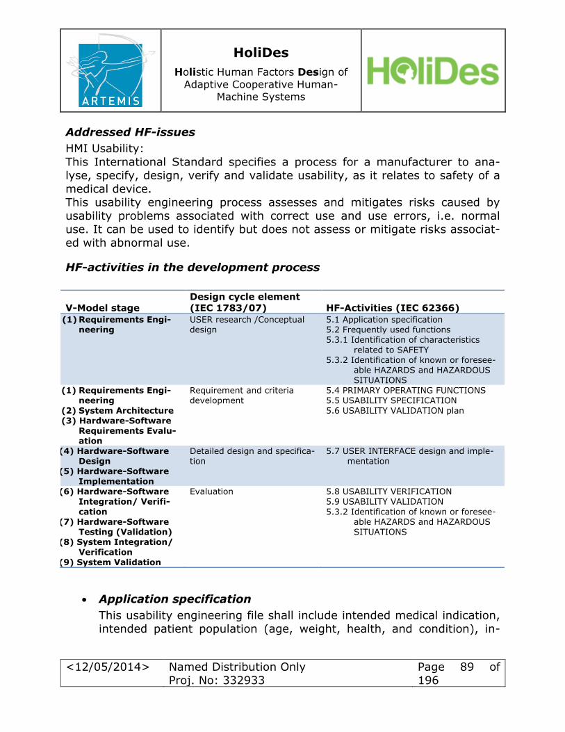
HoliDes
Holistic Human Factors Design of
Adaptive Cooperative Human-
Machine Systems
<12/05/2014> Named Distribution Only
Proj. No: 332933
Page 89 of
196
Addressed HF-issues
HMI Usability: This International Standard specifies a process for a manufacturer to ana-
lyse, specify, design, verify and validate usability, as it relates to safety of a
medical device.
This usability engineering process assesses and mitigates risks caused by usability problems associated with correct use and use errors, i.e. normal
use. It can be used to identify but does not assess or mitigate risks associat-
ed with abnormal use.
HF-activities in the development process
V-Model stage
Design cycle element
(IEC 1783/07) HF-Activities (IEC 62366)
(1) Requirements Engi-neering
USER research /Conceptual design
5.1 Application specification 5.2 Frequently used functions 5.3.1 Identification of characteristics
related to SAFETY 5.3.2 Identification of known or foresee-
able HAZARDS and HAZARDOUS
SITUATIONS (1) Requirements Engi-
neering
(2) System Architecture (3) Hardware-Software
Requirements Evalu-ation
Requirement and criteria development
5.4 PRIMARY OPERATING FUNCTIONS 5.5 USABILITY SPECIFICATION
5.6 USABILITY VALIDATION plan
(4) Hardware-Software Design
(5) Hardware-Software
Implementation
Detailed design and specifica-tion
5.7 USER INTERFACE design and imple-mentation
(6) Hardware-Software Integration/ Verifi-
cation (7) Hardware-Software
Testing (Validation) (8) System Integration/
Verification (9) System Validation
Evaluation 5.8 USABILITY VERIFICATION 5.9 USABILITY VALIDATION
5.3.2 Identification of known or foresee-able HAZARDS and HAZARDOUS SITUATIONS
Application specification
This usability engineering file shall include intended medical indication,
intended patient population (age, weight, health, and condition), in-

HoliDes
Holistic Human Factors Design of
Adaptive Cooperative Human-
Machine Systems
<12/05/2014> Named Distribution Only
Proj. No: 332933
Page 90 of
196
tended part of the body or type of tissue to interact with, user profile,
conditions of use (e.g. location) and operating principle. Frequently used functions
List frequently used functions in the Usability Engineering File.
o Identification of characteristics related to SAFETY
An identification of characteristics related to safety (as part of a risk analysis) that focusses on usability shall be performed. Con-
sider application specification and frequently used functions.
o Identification of known or foreseeable HAZARDS and HAZARD-OUS SITUATIONS
Identify known or foreseeable hazards (as part of a risk analysis)
related to usability. The identification of hazards shall consider hazards to patients, users and other persons. Consider among
other things the preliminary use scenarios, possible use errors and a review of the user interface.
Primary Operating Functions The inputs to the Primary Operating Functions shall include the follow-ing:
o frequently used functions
o functions related to safety of the medical device Usability specification
The manufacturer shall develop the usability specification. The usability specification shall provide:
o testable requirements for usability verification; and
o testable requirements for usability of the primary operating func-tions including criteria for determining the adequacy of risk con-
trol achieved by the usability engineering process. Usability validation plan
The aim is to prepare and maintain a usability validation plan which specifies:
o any method used for validation of the usability of the primary oper-
ating functions;
o the criteria for determining successful validation of the usability of
the primary operating functions based on the usability specification; and
o the involvement of representative intended users.
The plan shall address frequent use scenarios and reasonably worst case use
scenarios.
User interface design and implementation

HoliDes
Holistic Human Factors Design of
Adaptive Cooperative Human-
Machine Systems
<12/05/2014> Named Distribution Only
Proj. No: 332933
Page 91 of
196
The manufacturer should conduct iterative design and development.
Usability engineering, including usability validation, should begin early and continue through the medical device design and development
lifecycle.
Usability verification
As part of the medical device design verification process, the manufac-turer shall verify the implementation of the medical device user inter-
face design against the requirements of the usability specification. The
results of the verification shall be recorded in the usability engineering file.
Usability validation
Usability of the medical device is validated according to the usability validation plan. The results shall be recorded in the Usability Engineer-
ing File. If the acceptance criteria documented in the usability validation plan
are not met: o further user interface design and implementation activities shall be
performed;
o or if further improvement is not practicable, the manufacturer may
gather and review data and literature to determine if the medical benefits of the intended use outweigh the risk arising from usability
problems. If this evidence does not support the conclusion that the medical benefits outweigh the risk, then the risk is unacceptable.
Note that many of these activities commonly occur in parallel. Interaction between steps occurs frequently, rapidly, and often seamlessly

HoliDes
Holistic Human Factors Design of
Adaptive Cooperative Human-
Machine Systems
<12/05/2014> Named Distribution Only
Proj. No: 332933
Page 92 of
196
Proposed methods
HF-Activities
(IEC 62366)
Proposed methods
(IEC 62366)
Output format
of methods
5.1 Application specification 5.2 Frequently used functions 5.3.1 Identification of characteris-
tics related to SAFETY
5.3.2 Identification of known or foreseeable HAZARDS and HAZARDOUS SITUATIONS
market research focus groups user interviews general task analysis*
cognitive task analysis* time-and-motion studies* Contextual inquiry and observation*
functional analysis* questionnaires and surveys*
Unformalized
5.4 PRIMARY OPERATING FUNC-TIONS
5.5 USABILITY SPECIFICATION 5.6 USABILITY VALIDATION plan
use error analysis questionnaires and surveys*
Unformalized
5.7 USER INTERFACE design and implementation
cognitive walk-through* design audits* expert reviews*
heuristic analysis* prototyping*
Unformalized
5.8 USABILITY VERIFICATION
5.9 USABILITY VALIDATION 5.3.2 Identification of known or
foreseeable HAZARDS and
HAZARDOUS SITUATIONS
usability testing field-testing*
workload assessment*
Unformalized
*further information concerning the method is given in the papers listed above
Additional information
The IEC 62366 describes a usability engineering process, and provides guid-
ance on how to implement and execute the process to provide safety in med-
ical devices. It applies knowledge about human behavior, abilities, limita-tions, and other characteristics related to the design of tools, devices, sys-
tems, tasks, jobs, and environments to achieve adequate usability as defined
in ISO 9241. The process shall address user interactions with the medical device including transport, storage, installation, operation, maintenance and
repair, as well as disposal.
The results of the Usability Engineering Process shall be recorded in the Usa-
bility Engineering File which is often part of the Risk Management File for the
Risk Management Process as defined in ISO 14971. It should contain refer-

HoliDes
Holistic Human Factors Design of
Adaptive Cooperative Human-
Machine Systems
<12/05/2014> Named Distribution Only
Proj. No: 332933
Page 93 of
196
ences or pointers to all required documentation of the Usability Engineering
Process. In IEC 62366 on page 24 a parallel combination of the Risk Man-agement Process and the Usability Engineering Process can be found.
No tools are given by the concept.
STRENGTHS-WEAKNESSES Analysis
Strengths: The concept Usability Engineering to Medical Devices has been described in
detail in IEC 62366. Therefore it is rated as a promising concept that has
proven its usefulness successfully. It combines the system development pro-cess with human factors activities taken form the usability engineering pro-cess. Additionally it also offers a combination to risk management. The con-
cept offers a variety of methods and stresses that usability engineering is not necessarily a serial process. It should be seen rather flexible with many ac-
tivities done in parallel and iteratively. Therefore Usability Engineering to Medical Devices is a flexible concept that can be combined with other activi-
ties. Moreover it covers the whole lifecycle of the medical devices. The concept covers a narrow group of human factor issues. Additionally there are many different methods offered that have not been mentioned by other
concepts. Therefore an adequate method can be chosen in a given situation.
Weaknesses: This concept does not offer a workflow how to develop usability specifications
and a usability validation plan. Since these specifications are the basis for further usability evaluations and validation it is necessary to conduct a com-plete plan. IEC 62366 comprises no guideline or standard procedure of how
to derive such specifications. There is no formalized output of the methods. So it is difficult to integrate different methods into a tool chain based work-
flow.
General evaluation and summary
IEC 62366 describes the steps to conduct a usability engineering process for the design of medical devices. All output should be recorded in a so called
Usability Engineering File. Specifics are missing and sensitive to interpreta-
tion, like the definition of a frequently used function. It requires a usability
engineering background to work with this standard. Fundamentally, the Usa-
bility Engineering Process is a user-centered process. That is, it is driven by user’s actual needs and is based on the premise that the user is always a
critical element of the system. The concept offers an opportunity how the
system development can be accompanied by human factor activities in order

HoliDes
Holistic Human Factors Design of
Adaptive Cooperative Human-
Machine Systems
<12/05/2014> Named Distribution Only
Proj. No: 332933
Page 94 of
196
to create a usable medical device that provides also safety to patients and
users.
5.1.2 Concept: Human-Centred Design in Medical Fields
Reference
Human-Centred Design in Medical Fields; N. Ando, N. Nakano, N, Tohyama;
2008
Application of the Concept
Domain: health System: health care information systems
The case study conducted by the authors focuses on the Electronic Medical Record (EMR) that allows physicians to enter medical orders such as labora-
tory tests, and information will then be sent to relate sections in the hospital.
Addressed HF-issues
HMI Usability, Information requirements

HoliDes
Holistic Human Factors Design of
Adaptive Cooperative Human-
Machine Systems
<12/05/2014> Named Distribution Only
Proj. No: 332933
Page 95 of
196
HF workflow in the development process
V-Model
steps
Supported by
the concept (original step)
HF-Activities
Methods Output format of
methods
Requirements Engineering
(Design Devel-
opment)
Analyzing current status
interviews
reviews unformalized
System Architec-
ture
H-S Require-ments Evaluation
H-S-Design
(Evaluation)
Usability Evalua-tion1
usability evaluation user analysis and task
analysis design image evaluation
color analysis evaluation
design guidelines (unformalized)
H-S-
Implementation
H-S Integration/ Verification
H-S Testing (Val-idation)
System Integra-tion/ Verification
(Improvement
Policy)
Formulation of De-sign Concept
Integration of design
guidelines taken from Usability Evaluations unformalized
System Valida-tion
STRENGTHS-WEAKNESSES-Analysis
Strengths
The concept Human-Centred Design in Medical Fields covers different steps of the system development process. It also shows how the results of the us-
ability evaluation shall be integrated into the formulation of the design con-
cept. The concept offers an approach of how to integrate the results of usability
evaluation into the design phase. The steps listed in the method section
comprise a lot of single methods that could be helpful in order to develop an
adequate system in medical fields.

HoliDes
Holistic Human Factors Design of
Adaptive Cooperative Human-
Machine Systems
<12/05/2014> Named Distribution Only
Proj. No: 332933
Page 96 of
196
Weaknesses
The concept offers a restricted range of methods. Moreover the methods mentioned are rather steps that need to be done. There is no further infor-
mation given what methods fall into the categories listed. Therefore the ade-
quate method needs to be chosen by the evaluator. Likewise only two human
factor issues are covered by the concept. There is no formalized output. So it is difficult to integrate different methods
into a chain of action. Only three steps of the system development process
are addressed so it may be difficult to accompany the full system develop-ment process.
General evaluation and summary
Human-Centred Design in Medical Fields is a concept adopted from the gen-eral field of developing usable systems. Therefore it might also be applicable
to other domains even though the authors do not mention it. In contrast to other concepts the authors introduce how the results of the usability evalua-
tion are integrated into the design concept. Nonetheless, the concept is not yet fully integrated into the medical fields and more research needs to be done in order to be able to tackle the other human factors issues. There are-
no toolsgiven by the concept.
5.1.3 Concept: Usability Engineering
Reference
Evaluation in the design of health information systems: application of approaches emerging from usability engineering; A.W. Kushniruk; 2002
Cognitive and usability engineering methods for the evaluation of clini-
cal information systems; A.W. Kushniruk, V.L. Patel; 2004
Application of the Concept
Domain: health
System: health care information systems A case study using the concept evaluated the Doctor’s Outpatient Practice
System (DOP). That system allows clinicians to record patient problems, al-
lergies, and medications.
Addressed HF-issues
HMI Usability, Information requirements
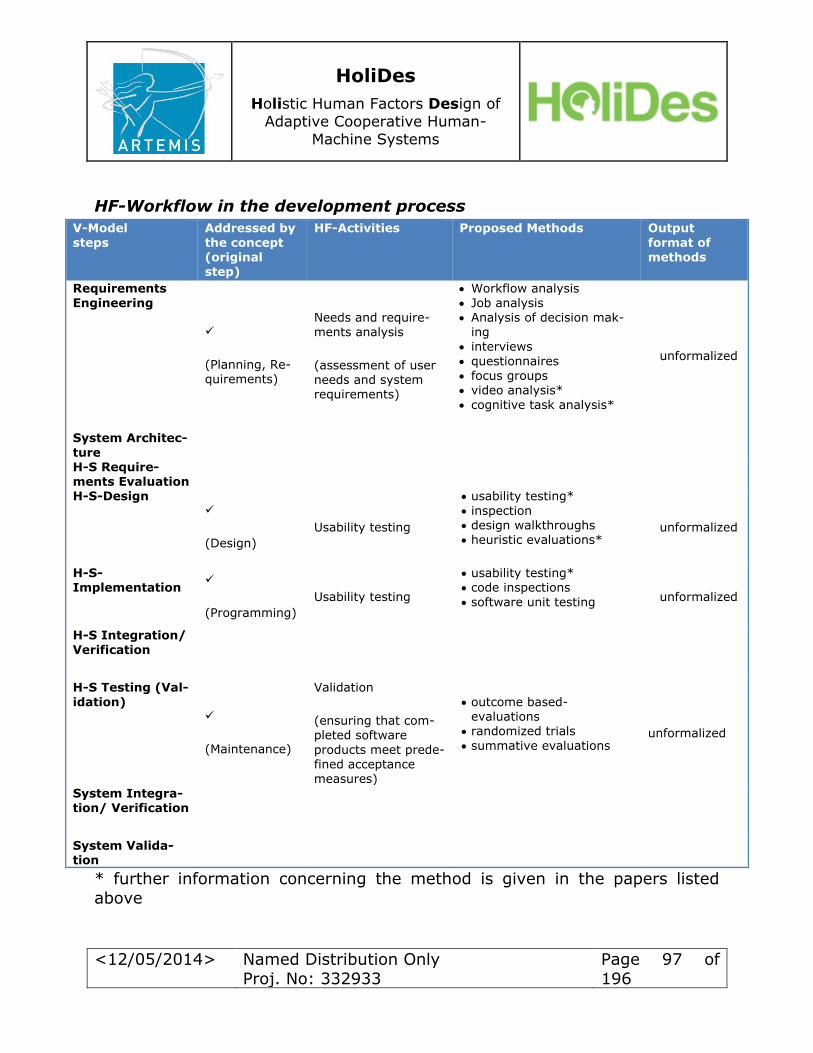
HoliDes
Holistic Human Factors Design of
Adaptive Cooperative Human-
Machine Systems
<12/05/2014> Named Distribution Only
Proj. No: 332933
Page 97 of
196
HF-Workflow in the development process
V-Model
steps
Addressed by
the concept (original step)
HF-Activities Proposed Methods
Output
format of methods
Requirements
Engineering
(Planning, Re-quirements)
Needs and require-ments analysis
(assessment of user needs and system requirements)
Workflow analysis
Job analysis Analysis of decision mak-
ing interviews
questionnaires focus groups video analysis*
cognitive task analysis*
unformalized
System Architec-
ture
H-S Require-ments Evaluation
H-S-Design
(Design)
Usability testing
usability testing*
inspection design walkthroughs heuristic evaluations*
unformalized
H-S-Implementation
(Programming)
Usability testing
usability testing* code inspections
software unit testing unformalized
H-S Integration/
Verification
H-S Testing (Val-
idation)
(Maintenance)
Validation
(ensuring that com-pleted software
products meet prede-fined acceptance measures)
outcome based-evaluations
randomized trials
summative evaluations unformalized
System Integra-tion/ Verification
System Valida-tion
* further information concerning the method is given in the papers listed
above
HoliDes
Holistic Human Factors Design of
Adaptive Cooperative Human-
Machine Systems
<12/05/2014> Named Distribution Only
Proj. No: 332933
Page 98 of
196
STRENGTHS-WEAKNESSES-Analysis
Strengths The concept Usability Engineering covers different steps of the system devel-
opment process. Moreover it offers a variety of methods to choose from.
By applying the concept the HF issues HMI Usability and Information re-
quirements can be tackled throughout the system development. It focusses on a narrow group of human factor issues. Moreover there are
different methods offered. Depending on the situation an appropriate method
can be chosen. Due to its general form the concept might also be applied to other domains. Weaknesses
The concept barely describes how to use the methods in an appropriate manner. Also there are no interpretation guidelines given, to help derive ex-
plicit improvements for the system in question. Moreover, it is not explained how the results shall be integrated into the next step of the system devel-
opment. The outputs are also not formalised. Another weakness concerns the focus on only two HF issues out of the group “human in system”. It is neither described how the approach of Usability En-
gineering can also be used in order to tackle other HF issues, nor it is denied
that other HF issues may be supported by applying the concept. There is no formalised output of the methods. So it is difficult to integrate
different methods into a chain of action. It is not clear how the methods may influence the use of other methods.
General evaluation and summary
Usability Engineering tries to tackle the fast development of complex infor-mation systems within the domain of health and medical equipment. Due to
its young age, the methods offered are not explained in detail; however the
variety of methods given allows one to adequately choose a method suitable
for the system in question. Moreover, even though only one main HF issue is covered, the concept shows how it can be resolved during many stages of
the system development process. This might also be done with other HF is-
sues but further research needs to be done here. The concept provides no
tools.

HoliDes
Holistic Human Factors Design of
Adaptive Cooperative Human-
Machine Systems
<12/05/2014> Named Distribution Only
Proj. No: 332933
Page 99 of
196
5.1.4 Concept: Human Factors Engineering and Risk Management
Reference Medical Device Use-Safety: Incorporating Human Factors Engineering into
Risk Management; U.S. Department of Health and Human Services Food and
Drug Administration; 2000
Application of the Concept
Domain: health
System: all systems with human interaction
Addressed HF-issues
Human in System >> Human Machine Interaction with focus on safety and use-related hazards
HF-Workflow in the development process
V-Model steps
Addressed by the
concept
HF-Activities Proposed Methods Output format of methods
Requirements Engineering
Identify and describe use scenarios resulting in hazards.
Prioritize and assess use-related hazards.
Device Use Description
Standards and Guidelines* Analytical and Empirical
Approaches
Priorization and Assess-ment
unformalized
System Architec-ture
H-S Require-ments Evaluation
H-S-Design
H-S-
Implementation
Develop and implement mitigation and control
strategies for use-related hazards.
Standards and Guidelines*
Analytical and Empirical Approaches
Mitigate and Control use-related hazards
unformalized
H-S Integration/
Verification
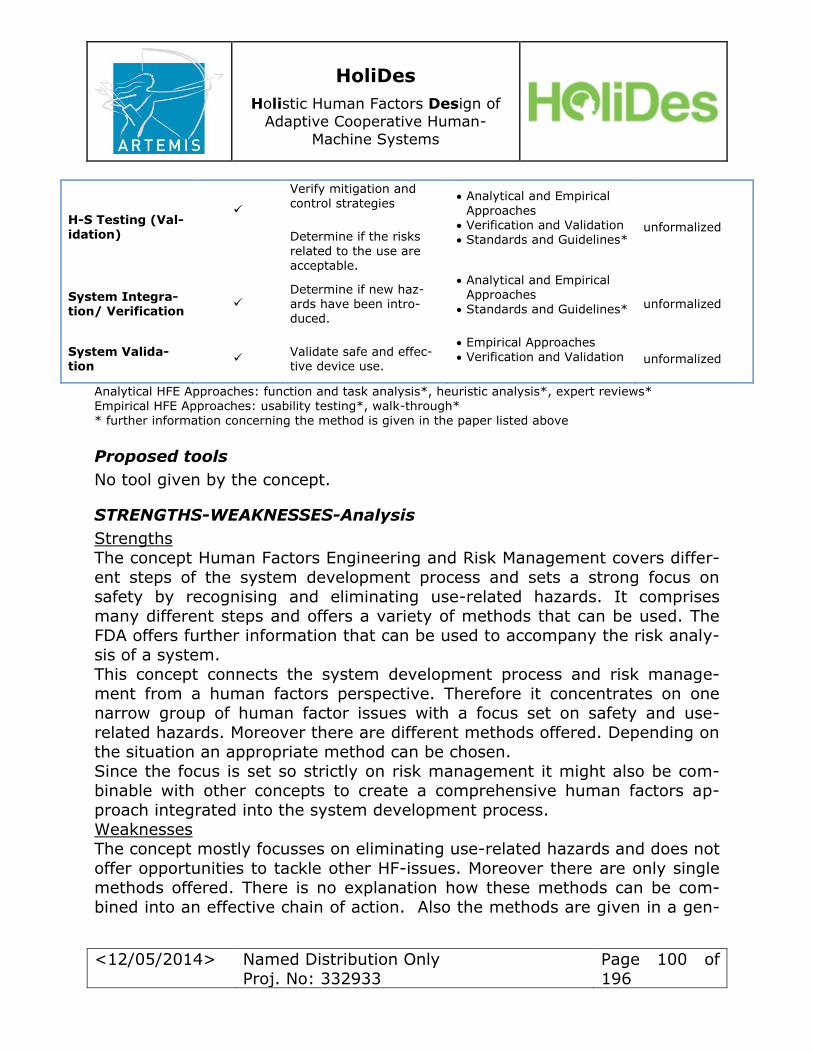
HoliDes
Holistic Human Factors Design of
Adaptive Cooperative Human-
Machine Systems
<12/05/2014> Named Distribution Only
Proj. No: 332933
Page 100 of
196
H-S Testing (Val-
idation)
Verify mitigation and
control strategies
Determine if the risks
related to the use are acceptable.
Analytical and Empirical
Approaches Verification and Validation Standards and Guidelines*
unformalized
System Integra-tion/ Verification
Determine if new haz-ards have been intro-duced.
Analytical and Empirical Approaches
Standards and Guidelines* unformalized
System Valida-tion
Validate safe and effec-tive device use.
Empirical Approaches
Verification and Validation unformalized
Analytical HFE Approaches: function and task analysis*, heuristic analysis*, expert reviews* Empirical HFE Approaches: usability testing*, walk-through*
* further information concerning the method is given in the paper listed above
Proposed tools
No tool given by the concept.
STRENGTHS-WEAKNESSES-Analysis
Strengths
The concept Human Factors Engineering and Risk Management covers differ-
ent steps of the system development process and sets a strong focus on
safety by recognising and eliminating use-related hazards. It comprises many different steps and offers a variety of methods that can be used. The
FDA offers further information that can be used to accompany the risk analy-sis of a system.
This concept connects the system development process and risk manage-ment from a human factors perspective. Therefore it concentrates on one
narrow group of human factor issues with a focus set on safety and use-
related hazards. Moreover there are different methods offered. Depending on the situation an appropriate method can be chosen.
Since the focus is set so strictly on risk management it might also be com-
binable with other concepts to create a comprehensive human factors ap-proach integrated into the system development process.
Weaknesses
The concept mostly focusses on eliminating use-related hazards and does not
offer opportunities to tackle other HF-issues. Moreover there are only single methods offered. There is no explanation how these methods can be com-
bined into an effective chain of action. Also the methods are given in a gen-

HoliDes
Holistic Human Factors Design of
Adaptive Cooperative Human-
Machine Systems
<12/05/2014> Named Distribution Only
Proj. No: 332933
Page 101 of
196
eral manner so that it can be hard to find an appropriate way of applying
them to a given system. There is no formalised output of the methods. So it is difficult to integrate
different methods into a chain of action. It is not clear how the methods may
influence the use of other methods.
General evaluation and summary
Human Factors Engineering and Risk Management has a strong focus on
safety in contrast to other concepts. The FDA introduces a detailed concept
that shall help to prevent patients and users from harm by interacting with a product and offers different methods how this can be achieved. As risk man-agement has its own domain of analysis this concept might also be combina-
ble with other human factors concepts out of the health domain.
5.1.5 Human Factors and Usability Engineering
Reference
Usability Engineering in der Medizintechnik; C. Backhaus; 2010
Applying Human Factors and Usability Engineering to Optimize Medical
Device Design; U.S. Department of Health and Human Services Food
and Drug Administration; 2011 Human Factors Engineering: A Tool for Medical Device Evaluation in
Hospital Procurement Decision Making; G. Ginsburg; 2005 Introduction to the Human Factors Engineering Series; J. Gosbee;
2004 Patient Safety, Potential Adverse Drug Events, and Medical Device De-
sign: A Human Factors Engineering Approach; Lin et al.; 2001
Application of the Concept
Domain: health System: all systems with human interaction
Addressed HF-issues
There are none explicitly stated but the HF-issues covered by the use cases
comprise issues taken from the categories:
6 Human in System Human Machine Interaction.
o HMI Usability
o Information requirements

HoliDes
Holistic Human Factors Design of
Adaptive Cooperative Human-
Machine Systems
<12/05/2014> Named Distribution Only
Proj. No: 332933
Page 102 of
196
o Output devices
4 Procedures, Roles and Responsibilities Working Method
o Task Demand
o Complexity
More issues might also be covered by the concept of human factors and usa-bility engineering.
HF-Workflow in the development process
V-Model steps
Supported by the concept
(original step)
HF-Activities
Proposed Methods Output for-mat of
methods
Requirements Engineering
(Process Analy-sis)
Process Analysis
participative process anal-ysis*
task analysis field observations
process flow diagrams
System Architec-
ture
H-S Require-ments Evaluation
H-S-Design Usability Evaluation
of Mock-up
focus groups* expert reviews questionnaires
H-S-Implementation
H-S Integration/
Verification
H-S Testing (Val-idation)
Usability Evaluation of interface
cognitive walkthrough* simulated use testing* checklists*
System Integra-tion/ Verification
System Valida-tion
Usability Evaluation of product
heuristic evaluation* thinking aloud technique questionnaires (System-
Usability-Scale, Nasa-TLX)
* further information concerning the method is given in the papers listed above

HoliDes
Holistic Human Factors Design of
Adaptive Cooperative Human-
Machine Systems
<12/05/2014> Named Distribution Only
Proj. No: 332933
Page 103 of
196
Additional information
The authors introduce the concept of human factors and usability engineer-ing as a general concept that should be applied iteratively throughout and
closely coupled with the system development process. Human factors activi-
ties should be applied as early as possible. The scope of the concept embrac-
es device users, device use environments and device user interfaces. At eve-ry stage of the system development process these factors should be kept in
mind.
Nonetheless, the authors do not state which human factors activities should be performed at what stage of the development process. The HF activities listed above are taken from the use case “Produktentwicklung einer Infu-
sionstherapiebaureihe” (engl. system development of an infusion instrument) described by Backhaus and should be seen as a possible arrangement. The
methods offered for the different human factors activities are collected from the different authors.
STRENGTHS-WEAKNESSES-Analysis:
Strengths
In general the concept Human Factors and Usability Engineering as it is de-scribed by the authors can be applied to all systems that require human in-
teraction. By applying the concept different human factors issues can be tackled, mainly of the group Human in System. Probably other issues could
also be resolved by the concept. The use cases as they are described by the authors show how it can be used as a structured schema that can be applied along the system development
process and offers methods to choose from. Concerning the methods listed above, most of them can be found in different publications. Therefore they
seem to be very promising in developing a sound system.
Due to its general form the concept might be applied to different human fac-
tor issues and domains. As most the methods listed above are proposed by more than one author, they are can be regarded as strong and promising
tools.
Weaknesses
The authors do not describe a structured plan of action. They describe a
general concept that can be realized in many ways. Moreover they are not explicitly stating what human factors issues can be solved; they are rather
speaking of the development of a sound and usable system.
The methods listed are taken from different publications dealing with the
concept of Human Factors and Usability Engineering. Therefore it is not clear
HoliDes
Holistic Human Factors Design of
Adaptive Cooperative Human-
Machine Systems
<12/05/2014> Named Distribution Only
Proj. No: 332933
Page 104 of
196
whether they can influence each other. Additionally only one use case offers
a structured plan of human factors activities along to the system develop-ment process. Therefore other arrangements of HF-activities might be possi-
ble. The concept does not provide any tools.
General evaluation and summary
Human Factors and Usability Engineering is a concept that has been de-scribed by many authors and is commonly accepted. Therefore it can be re-
garded as a strong and sound concept. Most of the authors offer the same
methods that are described in more detail in their publications. This again supports the strength of the concept. All in all the concept should be closely connected to the system development
process in order to create sound products and equipment and to eliminate different human factor issues.
5.2 HF and Safety Regulations in Healthcare Domain
5.2.1 General requirements for basic safety and essential
performance. Collateral standard: Usability
Reference
IEC 60601-1-6 General requirements for basic safety and essential perfor-mance. Collateral standard: Usability; IEC International Electrotechnical
Commission; 2010
Application of the regulation
Domain: Healthcare System: Medical electrical equipment
Addressed HF-issues
This International Standard specifies a process for a manufacturer to ana-
lyse, specify, design, verify and validate usability, as it relates to basic safety and essential performance of medical electrical equipment.
This usability engineering process assesses and mitigates risks caused by
usability problems associated with correct use and use errors, i.e. normal use. It can be used to identify but does not assess or mitigate risks associat-
ed with abnormal use.
HoliDes
Holistic Human Factors Design of
Adaptive Cooperative Human-
Machine Systems
<12/05/2014> Named Distribution Only
Proj. No: 332933
Page 105 of
196
Proposition of HF-activities during development process
The object of this collateral standard is to specify general requirements that are in addition to those of the general standards and to serve as the basis for
particular standards.
HF workflow
A usability engineering process complying with IEC 62366 shall be per-formed.
Additional information
This document describes requirements in the following areas:
General requirements for basic safety and essential performance
Tests and guidance for alarm systems in medical electrical equipment
and medical electrical systems
Conditions for application to ME equipment
Usability engineering process for ME equipment
General evaluation and summary
IEC 60601-1-6 describes in general terms the requirements and rationales
for the manufacturer to analyse, specify, design, verify and validate the usa-bility of ME equipment.
5.2.2 General requirements for basic safety and essential performance. Collateral standard: General requirements,
tests and guidance for alarm systems in medical electrical equipment and medical electrical systems
Reference
IEC 60601-1-8 General requirements for basic safety and essential
performance. Collateral standard: General requirements, tests and
guidance for alarm systems in medical electrical equipment and medi-
cal electrical systems; IEC International Electrotechnical Commission; 2012
ANSI/AAMI HE48-1993, Human factors engineering guidelines and pre-
ferred practices for the design of medical devices BLOCK, FE. Jr. Human factors and alarms. Chapter 2 In Lake CL., ed.
Clinical Monitoring for Anaesthesia & Intensive Care. Philadelphia, WB
Saunders, 1994, p. 11-34.
HoliDes
Holistic Human Factors Design of
Adaptive Cooperative Human-
Machine Systems
<12/05/2014> Named Distribution Only
Proj. No: 332933
Page 106 of
196
EDWORTHY J. Urgency mapping in auditory warning signals. In Stan-
ton, N., Editor: Human Factors in alarm design. London: Taylor and Francis, 1994.
Application of the regulation
Domain: Healthcare
System: Medical electrical equipment
Addressed HF-issues
Visual alarm signals and information signals: Multiple-purpose computer-generated graphic displays should be designed in accordance with modern
human interface design principles. Attention is drawn to IEC 62366.
Termination of inactivation of ALARM SIGNALS: It is important for an opera-tor to be able to undo an action made in error. Patient safety requires this,
as human error is inevitable and the ability to mitigate error needs to be provided.
Additional information
Medical electrical equipment and MEDICAL ELECTRICAL SYSTEMS are in-
creasingly used in medical practice. ALARM SIGNALS are frequently used to indicate unsatisfactory physiological PATIENT states, unsatisfactory function-
al states of the Medical electrical equipment or medical electrical system or to warn the operator of hazards to the patient or operator due to the medical
electrical equipment or medical electrical system. Information signals convey information that is independent of an alarm condition.
Surveys of healthcare personnel have indicated significant discontent with
alarm signals. Problems include difficulty in identifying the source of an
alarm signal, loud and distracting alarm signals, and the high incidence of false positive or negative alarm conditions.
Surveys of manufactures of medical monitors demonstrated a wide variety of
default alarm settings. The leading reason for disabling alarm signals is the large number of alarm signals associated with false positive alarm conditions.
Safety of patients depends on the ability of the operator to correctly discern
the characteristics of alarm signals. Usability is an important element in the
design of alarm signals that are readily discernible without being unneces-
sarily distracting or disturbing. This approach is intended to rationalize the
current situation, to reduce confusion by limiting proliferation of alarm sig-nals and their control states, and to minimize distraction for other people.

HoliDes
Holistic Human Factors Design of
Adaptive Cooperative Human-
Machine Systems
<12/05/2014> Named Distribution Only
Proj. No: 332933
Page 107 of
196
This collateral standard was developed with contributions from clinicians, en-
gineers and applied psychologists. This document describes requirements in the following areas:
General requirements for basic safety and essential performance
Tests and guidance for alarm systems in medical electrical equipment
and medical electrical systems ME equipment identification marking, labelling/symbols documents
Alarm systems (Visual alarm signals, auditory alarm signals, verbal
alarm signals) Alarm system delays
Alarm settings
Alarm limits Alarm system security
Alarm signal inactivation states Alarm reset
Distributed alarm system Alarm logging
General evaluation and summary
IEC 60601-1-8 describes the requirements, tests and guidance for alarm sys-
tems in medical electrical equipment. This is accomplished by defining alarm categories (priorities) by degree of urgency, consistent alarm signals and
consistent control states and their marking for all alarm systems. The docu-ment gives very detailed and specific requirements for alarm signals and their characteristics, but it does not provide any HF activities or workflow.
5.2.3 Particular requirements for basic safety and essential
performance of magnetic resonance equipment for medical diagnosis
Reference
IEC 60601-2-33 Particular requirements for basic safety and essential performance of magnetic resonance equipment for medical diagnosis;
IEC International Electrotechnical Commission; 2013
Application of the regulation
Domain: Healthcare
System: Magnetic resonance equipment for medical diagnosis

HoliDes
Holistic Human Factors Design of
Adaptive Cooperative Human-
Machine Systems
<12/05/2014> Named Distribution Only
Proj. No: 332933
Page 108 of
196
Addressed HF-issues
Human in system (required system behaviours, labels, controls and performance)
Working environment (working positions, electromagnetic fields expo-
sure)
Training and development (i.e. warnings in Instructions for Use)
Additional information
This International Standard addresses technical aspects of the medical diag-nostic MR System and the MR Equipment therein related to the safety of pa-
tients examined with this system, the safety of the MR worker involved with its operation and the safety of the MR worker involved with the development,
manufacturing, installation, and servicing of the MR System. The standard describes requirements in the following areas:
General requirements General requirements for testing of ME Equipment
Classification of ME Equipment and ME Systems ME Equipment identification, marking and documents
Protection against electrical Hazards from ME Equipment Protection against mechanical Hazards of ME Equipment and ME Sys-
tems Protection against unwanted and excessive radiation Hazards
Protection against excessive temperatures and other Hazards Accuracy of controls and instruments and protection against hazardous
outputs
Hazardous Situations and fault conditions Programmable electrical medical system (PEMS)
Construction of ME Equipment and ME Systems
Electromagnetic compatibility of ME Equipment and ME Systems
Electromagnetic compatibility – Requirements and tests
General evaluation and summary
IEC 60601-2-33 does not describe a HF process, but lists technical require-
ments for the design of MR systems. It is quite specific, but interpreting the
requirements requires extensive domain knowledge of the engineer. There
are no HF activities or workflow provided.
HoliDes
Holistic Human Factors Design of
Adaptive Cooperative Human-
Machine Systems
<12/05/2014> Named Distribution Only
Proj. No: 332933
Page 109 of
196
5.2.4 Particular requirements for basic safety and essential
performance of X-ray equipment for interventional procedures
Reference
IEC 60601-2-43 Particular requirements for basic safety and essential per-
formance of X-ray equipment for interventional procedures; IEC International Electrotechnical Commission; 2010
Application of the regulation
Domain: Healthcare
System: X-ray equipment for radioscopically guided interventional proce-dures
Addressed HF-issues
Human in system (required system behaviours, labels, controls and
performance) Working environment (working positions, radiation)
Training and development (i.e. warnings in Instructions for Use)
Additional information
This International Standard addresses technical aspects of the medical diag-nostic MR System and the MR Equipment therein related to the safety of pa-
tients examined with this system, the safety of the MR worker involved with its operation and the safety of the MR worker involved with the development,
manufacturing, installation, and servicing of the MR System. The standard describes requirements in the following areas:
General requirements General requirements for testing of ME Equipment
Classification of ME Equipment and ME Systems
ME Equipment identification, marking and documents Protection against electrical Hazards from ME Equipment
Protection against mechanical Hazards of ME Equipment and ME Sys-
tems
Protection against unwanted and excessive radiation Hazards Protection against excessive temperatures and other Hazards
Accuracy of controls and instruments and protection against hazardous
outputs Hazardous Situations and fault conditions

HoliDes
Holistic Human Factors Design of
Adaptive Cooperative Human-
Machine Systems
<12/05/2014> Named Distribution Only
Proj. No: 332933
Page 110 of
196
Programmable electrical medical system (PEMS)
Construction of ME Equipment and ME Systems Electromagnetic compatibility of ME Equipment and ME Systems
Electromagnetic compatibility – Requirements and tests
Radiation protection in diagnostic X-ray equipment
General evaluation and summary
IEC 60601-2-43 does not describe a HF process, but lists technical require-
ments for the design of x-ray equipment. It is quite specific, but interpreting
the requirements requires extensive domain knowledge of the engineer. There are no HF activities or workflow provided.
5.3 Conclusions
Bearbeiten: Konzentration in erster Linie auf Usability, andere Issues werden selten behandelt. Annahne, dass Erfüllung von Usability Kriterien verspricht
gleichzeitig die Erfüllung von Safety Anforderungen. Die Regularien und Konzepte sind wenig produkt bzw. Domainspezifisch, an-
ders als bei anderen Domänen. Die Diskussion ist eher generell und medical
ist marginal.
Tyspisch für AdCos: Adpativity, Intereoperabilität, Colaboration sind so gut wie gar nicht vorhanden.
The concepts for human factors integration in the domain of healthcare de-
scribed above, set a main focus on HF issues that are concerned with the
HMI and safety. Mostly the concepts cover issues such as interface usability
and information requirements in order to develop a safe and sound system.
Neither the user nor the patient shall suffer any harm. Use cases applying
the concepts that were described by the authors also focussed on the inter-
face design of output devices, task demands and their complexity.
In order to resolve the HF issues, the system in question shall be character-
ised by a good usability such that the system can be used effectively and
safely, efficiently and with satisfaction. In general the actual end user should
be included throughout the whole system development process. This can be
achieved by needs and requirements analysis of the users and the system,
as well as task analysis. This provides information to the interface design
about essential criteria in terms of usability requirements, which need to be
fulfilled by the system. Additionally all implementation steps of the system
HoliDes
Holistic Human Factors Design of
Adaptive Cooperative Human-
Machine Systems
<12/05/2014> Named Distribution Only
Proj. No: 332933
Page 111 of
196
(graphical Mock-up, prototype, full implementation) should be accompanied
by usability tests on different levels suitable for the status of development
(i.e. cognitive walkthroughs, heuristic evaluations or field studies with poten-
tial end users). By doing so, usability criteria and requirements can be vali-
dated. If the system does not meet the requirement a redesign can be done.
As the concepts mainly concentrate on an effective, safe, efficient and satis-
factory use they do not raise extra focus on specific aspects of AdCoS such
as adaptivity, cooperation, and communication as defined in T1.1. However,
AdCoS in the domain of healthcare are not as complex as in other domains.
Even though there are many users of a system, the main feature of these
systems as described in use Case Deliverable 6.1 is displaying information
and allowing functionality according to user status. These special user needs
and the connected safety issues can be incorporated by following the work-
flows of the concept described above (i.e. conducting user and task analysis,
analysis of hazards). Also the special needs of communication and coopera-
tion within AdCoS in healthcare, can be treated like this if they can be re-
garded as general system requirements. Summing up, the concepts of hu-
man factors integration within the domain of healthcare do not set an explicit
focus on the special HF aspects raised by AdCoS. They also seems to be
more generic and less domain-specific comparing with other domains.
Like the concepts of human factors integration in the domain of healthcare,
the regulations in the same domain also set a focus on issues of the category
HMI, comprising of a usable design of the systems, information representa-
tion and alert signals. HF issues, which are additionally covered by the regu-
lations are the working environment, training and development. In contrast
to the concepts, almost no HF workflows are offered to resolve the issues in
question. Only IEC 62366 offers a procedure on how issues can be detected
and evaluated. IEC 60601-1-6 and IEC 60601-1-8 are also referring to these
HF activities. IEC 60601-2-33 and IEC 60601-2-43 do not describe any HF
activities. They depict technical regulations for the implementation of the
systems.
HoliDes
Holistic Human Factors Design of
Adaptive Cooperative Human-
Machine Systems
<12/05/2014> Named Distribution Only
Proj. No: 332933
Page 112 of
196
IEC 62366 describes four procedures that need to be conducted: user re-
search and conceptual design, requirement and criteria development, de-
tailed design and specification, and evaluation of the system. The usability
validation plan and the usability specification are the main documents that
are necessary to evaluate and validate the system. Here the system re-
quirements are described in a testable manner.
Similar to the concepts of human factors integration in the domain of
healthcare, the regulations also do not cover the special aspects of AdCoS.
Since IEC 62366 is the only regulation offering HF activities, the issues of
AdCoS (adaptivity, cooperation, and communication) can only be integrated
if they are explicitly added to the usability specifications and to the usability
evaluation plan. The manufacturer and HF experts have to develop their own
criteria on how these aspects have to be implemented and tested. There are
no standards given.
Summing up, the regulations and concepts described in the domain of
healthcare, offer opportunities on how various HF issues can be resolved
parallel to the system development process. None of these explicitly mention
how the specific aspects of AdCoS can be considered; nonetheless, these as-
pects are also not excluded by the concepts and regulations. It is the respon-
sibility of the manufacturer and HF experts to include these issues in the HF
activities that accompany the system development.

HoliDes
Holistic Human Factors Design of
Adaptive Cooperative Human-
Machine Systems
<12/05/2014> Named Distribution Only
Proj. No: 332933
Page 113 of
196
6 Automotive Domain
6.1 HFI Concepts and Tools in Automotive Domain
6.1.1 Code of Practice for the Design and Evaluation of ADAS
Reference
Code of Practice for the Design and Evaluation of ADAS (CoP); Knapp, A.; Neumann, M.; Brockmann, M.; Walz, R.; Winkle, T.; 2009
Application of the concept
The CoP has been produced by a group of experts within the RESPONSE 3 project, a subproject of the integrated project PReVENT (ended in 2008), a
European automotive industry activity, co-funded by the European Commis-sion, to contribute to road safety by developing and demonstrating preven-
tive safety applications and technologies. It applies to the automotive do-main and is not applicable to other domains, as the key concept and corner-stone of the CoP is the concept of controllability. It spans the entire devel-
opment process. The CoP comprises a suitable ADAS (Advanced Driver Assis-
tance System) description concept including specific requirements for system
development. It summarises best practices and proposes methods for risk
assessment and controllability evaluation. “The Code of Practice applies to advanced driver assistance systems (ADAS).
It is not specifically intended to be applied to systems providing vehicle sta-bilization (such as ABS and ESP) or mere information and communication systems (such as navigation, systems and telephones). It may be applicable
to systems including vehicle to vehicle communication, but will not cover these completely.” (p. 2)
“Focus of the CoP is the system design against the background of system
controllability and the total vehicle from the field of view of Human Machine Interaction.” (p. 2)
“The CoP deals with specification and assessment of advanced driver assis-
tance systems during the entire development phase.” (p. 2) Addressed systems are Advanced Driver Assistance Systems in the form of
“various vehicle types and systems with many complexity and integration
levels in all ADAS” (p.3).
Due to the ADAS limits of their environmental sensing systems, the usage of
the assistance functionality will also be limited. This implies that a direct in-
HoliDes
Holistic Human Factors Design of
Adaptive Cooperative Human-
Machine Systems
<12/05/2014> Named Distribution Only
Proj. No: 332933
Page 114 of
196
teraction between the driver and the system is necessary. This interaction
has to be controllable also with regard to current legislation (Vienna Conven-tion). Thus, the CoP serves as a support tool for the engineer engaged in the
development of ADAS.
Addressed HF-issues
The current status of development makes it very difficult to describe the state-of-the-art knowledge of ADAS, because there are so many systems
with different technology addressing even more different assisting functions.
Risks of ADAS may be highly complex. The term "defective product" is used in the European Product Liability Directive not only in a technical sense but it is also linked to human factors (HF) including system requirements such as
dependability, controllability, comprehensibility, predictability and misuse re-sistance. Currently the technological safety issues are standardised within
ISO TC22, while RESPONSE 3 is focussing on the human-machine interaction (HMI) safety issues of ADAS, in particular on driver controllability, an ADAS
key issue. Within the six categories of Eurocontrol (2007) categories of Human Factors issues the Code of Practice addresses category 6 Human in System. The CoP
is explicit on the issues of 6.1 Human machine interaction, but also deals
with aspects of 6.2 System. These subjects are covered partially in checklists for the single issues, but also appear as general topics throughout the CoP.
The CoP defines ADAS as systems, which (among others) require “direct in-teraction between the driver and the system” (p. 4). Both Human Machine Interfaces and Human Machine Interaction are therefore core issues of the
CoP (primarily Annex A). System reliability is addressed in Annex C “General methods for safety analysis”. For each topic extensive empirical methods are
suggested
Addressed and supported development stages
The CoP defines its own development process (p. 11pp). It is not only a
compilation of currently available procedures, but also offers clues for deter-
mining activities to be performed during the individual development phases.
The focus is the system design against the background of system and vehicle
controllability from the field of view of HMI. The CoP deals with specification, realisation and assessment of ADAS, gathering the best practices of the
partner companies and also considers legal requirements.

HoliDes
Holistic Human Factors Design of
Adaptive Cooperative Human-
Machine Systems
<12/05/2014> Named Distribution Only
Proj. No: 332933
Page 115 of
196
The generic development process, describing the CoP, is provided as follows,
reflecting the logical sequence of product development phases of a product development, as well as selected milestones, but not necessarily their time
sequence (Figure 6-1).
Concept Phase Series Development
Requirements
Specification
System
Specification
Start of
Production
VerificationDefinition phaseBest concept
selection
Proof of
Concept
Validation
&Sign off
Detailed
Design
Concept Phase Series Development
Requirements
Specification
System
Specification
Start of
Production
VerificationDefinition phaseBest concept
selection
Proof of
Concept
Validation
&Sign off
Detailed
Design
6-1: Phases of COP development process
Therefore, it corresponds to a simplified presentation of reality. Possible iter-
ation loops accompanying individual development phases are not shown. It consists of a Concept Phase and a Series Development phase. Both phases
are rather self-explanatory: The Concept Phase consists of the Definition Phase, the Best Concept Selection Phase and the Proof of Concept Phase.
The Series Development starts with a Detailed Design, which probably re-flects the need for a product moving towards series development to be speci-fied in a way suitable for mass production. This stage is followed by Verifica-
tion and Validation, consisting of proofs of the correct system functions’ exe-cution and the safety of the functions themselves.
The Concept Phase and Series Development Phase equate roughly the
downward and the upward arrow of the V-Model. This relation deviates con-cerning the Detailed Design phase, though. In the V-Model it comes neces-
sarily before the implementation. This discrepancy probably reflects the spe-
cific needs of the auto industry: a full-fledged product specification for mass
production differs from the making of a single piece of software. In a certain sense the CoP’s cycle therefore consists of two V-Models, one for the Con-
cept and the other for the Series Development phase.
This development process is applied completely with regard to a new devel-
opment of an ADAS (or AdCoS in our case) application. Hence, in case of
modifications (derivate or change) of existing systems, an impact analysis

HoliDes
Holistic Human Factors Design of
Adaptive Cooperative Human-
Machine Systems
<12/05/2014> Named Distribution Only
Proj. No: 332933
Page 116 of
196
should be performed to assess the relevant areas affected by the modifica-
tion. Each car manufacturer is responsible for the application and documen-tation of the COP, taking into consideration, that for a system with safety
implications, additional safety related activities are necessary (for the auto-
mobile industry requirements there is the ISO TC22/SC3/WG16).
Finally, the concept of controllability in the COP is a key requirement. Con-trollability refers to the entire ADAS-driver-environment interaction (or Ad-
CoS-driver-environment interaction, in our case) comprising of:
normal system use within system limits, usage at and beyond exceeding system limits and
usage during and after system failures.
Controllability is dependent on:
the possibility and driver’s capability, to perceive the criticality of a sit-uation
the drivers capability to decide on appropriate countermeasures (e.g. override, system switch-off)
the driver’s ability to perform the chosen countermeasure (e.g. reac-
tion time, sensory-motor speed, accuracy).
Controllability is a basic parameter in the automotive risk assessment (as
proposed in the draft of the functional safety standard ISO WD 26262-3). The schema is the following:
6-2: Architectural scheme of controllability
HoliDes
Holistic Human Factors Design of
Adaptive Cooperative Human-
Machine Systems
<12/05/2014> Named Distribution Only
Proj. No: 332933
Page 117 of
196
The RESPONSE 3 COP assists early controllability estimation and later con-
firmation by providing checklists and references to state-of-the-art evalua-tion methods.
At the end of the system development process, the COP recommends a Con-
trollability Final Proof, to confirm that sufficient controllability is achieved for
the production version of the system, in particular for intervening systems. This means that the development team has to verify that drivers will react as
previously anticipated or in an appropriate way in relevant scenarios.
Proposition of HF-activities during the development process
The CoP describes very concrete different process stages and the corre-sponding sub-stages at a high and detailed level. Parts of the detailed de-
scription are proposed activities, which could be conducted during the system development (p.12). Correspondingly, the CoP recommends a concrete work-
flow of the entire process based of one possible example (here: “controllabil-ity”, see p. 14). Furthermore, there are very specific recommendations of
corresponding actions, belonging to each stage in the process. The actions can be performed in each corresponding stage of the process and are pre-cisely defined in an instruction-based form of the CoP (see p. 16pp).
As an example, the use of the checklist procedure assists in the specification
of ADAS in order to consider aspects which may not be obvious right from the beginning. The hazard and risk analysis procedure provides assistance in
setting up a systematic analysis of driving situations in order to determine potential risks. To sum up, the CoP aims at serving as a guideline assisting persons involved
in ADAS development, in order to adhere to the state-of-the-art knowledge with respect to risk identification and risk assessment, as well as methodolo-
gy for the evaluation of driver controllability, following the process of RE-
SPONSE 3 project.
Proposition of methods
Based on the CoP development-process and the corresponding stages of the
process in combination with the resulting specific action-recommendations,
the CoP links a proposed method to each action-recommendation. Thus, for
each step and corresponding action-recommendations of the CoP a linked
method exists. Consequently, check lists are existing in the CoP, so that the realization of each addressed issue can be ensured (see p. 16 and A2). Un-
fortunately, the CoP does not provide a formalized result or output of these
methods, allowing more variability in results or outputs.

HoliDes
Holistic Human Factors Design of
Adaptive Cooperative Human-
Machine Systems
<12/05/2014> Named Distribution Only
Proj. No: 332933
Page 118 of
196
Proposition of tools
The CoP does not recommend or propose specific tools. Based on the meth-ods, tools could be derived and developed in a next step if necessary.
Additional information
Based on the lack of formalized results or outputs the CoP enables a dynamic
usage in the system-development process of the automobile domain.
STRENGTHS-WEAKNESSES-Analysis
Strengths The CoP focusses very explicit on safety and controllability. Correspondingly,
the CoP is very useful for functional safety. It is very detailed and explicit on the subjects it covers with good and specific material in the annex (e.g.,
checklists). Furthermore, the CoP is very easy to understand, which is due to the clear specification of the stages of the development process. Its structure
is clear and comprehensible. The CoP can be a basis for requirements inte-gration and relevant concepts could be taken into account for other domains.
The CoP takes standards and some HF-concepts into account, which are ap-
plicable for the automobile domain and operationalize these issues. One big
strength is that the CoP makes specific recommendations for actions in the development process with an HMI section, ergonomic information, the use of
other standards, and an extensive glossary (p A75pp). The application of the CoP is a possibility to demonstrate that state-of-the-
art (SOA) procedures in ADAS development have been applied, including risk identification, risk assessment and evaluation methodology. It can be used as guideline for the AdCoS development, taking into account the risk identifi-
cation and risk assessment; in particular for these areas of application:
Use of the checklist for the HMI design and development Application of the Controllability concept both for “Alarming AdCoS” (in
CRF demonstrator) and for “Autonomous AdCoS” (in IFS demonstra-
tor). The CoP is a very good basis for the development of a more generic concept
and development-process stages, which in turn are not specific for particular
domains. Furthermore, the specific actions and methods can deliver a useful
body of knowledge for the HF-RTP and AdCos development. Especially, the
concrete methods in the annex (e.g., checklists) can be useful in the next steps.
Weaknesses

HoliDes
Holistic Human Factors Design of
Adaptive Cooperative Human-
Machine Systems
<12/05/2014> Named Distribution Only
Proj. No: 332933
Page 119 of
196
In particular it is not certain how big the HF aspect of the CoP is. Further-
more, the verification and validation of the issues are addressed very late in the entire process and thus may not have an impact any more. In the CoP,
there is no concrete operationalisation of HF issues at all (e.g. workload).
Sometimes the language is very vague when it comes to the point (e.g. “…
the HMI should be designed in such a way that the driver will not solely rely on the system, but will also double check the situation”). Additionally, the
CoP is very weak on empirical issues (e.g. “The design of the test trials
needs to be carefully considered” - p A64). The arrangement of phases and corresponding processes are strongly influenced by economical considera-
tions, not by science. Furthermore, there are not enough explicit feedback
loops connecting the different development stages. The issue “Planning vali-dation scenarios” is mentioned too late in the entire process. The definition
of use cases or scenarios should be addressed earlier in the development process. Maybe the CoP is too industry related: economic considerations are
paramount - first concepts, then detailed development (e.g. details only oc-cur in the serial development phase). Finally, in the CoP it is not mentioned how requirements exactly fit into the entire development process.
The main limitations of CoP are:
Full autonomous systems are not foreseen. Communication is not explicitly considered
Information regarding on-board systems (such as navigator or phone) are not addressed.
The major risk is that the CoP does not at all fit for a proper deployment re-
lated to the HF-RTP or AdCos. Furthermore, the CoP is too domain specific for a general HF-deployment. Additionally, there is the risk that the phases,
recommended actions and methods could not fit for HF-RTP and AdCos. Fi-nally, the effort of implementing useful issues related to the HF-RTP or Ad-
Cos based on the CoP could be too high.
General evaluation
RESPONSE 3 has developed the CoP to provide the vehicle industry with the
tools and common understanding to overcome and to help manage the prob-
lems about safety concerns and the liability of Advanced Driver Assistance
Systems (ADAS). It is an exactly-worded guide, useful for the needs of re-search and development of ADAS within the automotive industry. Thus, the
CoP primarily serves the needs of the automotive industry, which is the
whole idea behind it. The advantage of the CoP lies in the specific action rec-
ommendations and the corresponding methods, mentioned in the annex. The

HoliDes
Holistic Human Factors Design of
Adaptive Cooperative Human-
Machine Systems
<12/05/2014> Named Distribution Only
Proj. No: 332933
Page 120 of
196
development process is reduced to its essential steps and stages, resulting in
the concept, which is handy to realise. All the check lists mentioned in the CoP are useful methods, supporting the entire development process. Fur-
thermore, the CoP is valuable as a framework under the concept of control-
lability. Other than that, parts could be used to get an overview of applicable
methods and standards for ADAS. The focus on the issues of “controllability”, which are in fact the key concept of CoP, restricts purposeful driver assis-
tance functionality. So nothing would be developed, that violates that con-
cept. Furthermore, the CoP only integrates requirements under the umbrella of system controllability from a driver’s point of view. And it only has limited
value as a tool for the broad exploration of possibilities for ADAS. Nonethe-
less, the CoP is a useful framework, which can be used as a starting point for the development of more generic concepts and development-process stages,
which are useful for different domains at the same time. RESPONSE 3 project has a follow-up at the moment, which is named RE-
SPONSE 4, inside the Integrated Project ADAPTIVE (started in January 2014, web-site not yet available). The main objectives of RESPONSE 4 are:
legal aspects to facilitate the introduction of automated driving func-
tions
additional requirements for safety validation to ISO26262 and other safety standards
provision of a harmonised glossary
To sum up, legal aspects, human-vehicle integration and evaluation method-
ologies will be investigated; these aspects should be taken into account also inside HOLIDES.
6.1.2 Detectability concept
Detectability (Engel and Curio,2013) is a concept from recent research and is
maintained by HoliDes Partner TWT GmbH Science & Innovation. In HoliDes
we are working on similar human centered development concepts. The origi-
nal focus of the detectability was in the visual domain for guiding attention. But it could have its applications in other perception modalities, or combina-
tions thereof, as well.
Reference
Detectability Prediction for Increased Scene Awareness. David Engel, and Cristóbal Curio. IEEE Intell. Transport. Syst. Mag. 5(4):146-157 (2013)
HoliDes
Holistic Human Factors Design of
Adaptive Cooperative Human-
Machine Systems
<12/05/2014> Named Distribution Only
Proj. No: 332933
Page 121 of
196
Application of the concept
Domain: Automotive; applicable to other domains, like aeronautics and many others as well, generic
System: Visual attention guidance mechanism; complexity of the system ap-
proach is reflected by a trained non-linear support vector regression machine
approach.
Adressed HF-issues
Demonstrated in Physical Environment but also relevant for Work place lay-out, Operator Working Position, Personal Factors: Physiological Factors,
Physiosocial Factors and Human in System:HMI, System.
Adressed and supported development stages
Hardware-Software Integration/Verification
Hardware-Software Testing (Validation)
System Integration/Verification
System Validation
Proposition of HF-activities during development process
Object detectability performance are required to be collected through specific
experimental dual task designs. The human performance, i.e. to visual detect certain objects/ events, can be tested after a general human-centered sys-
tem calibration step (across or within subject), e.g. during real-driving. The goal is to automatically predict detectabilities which can be exploited for at-
tention guidance HMIs.
Proposition of methods
Psychophysical simulations/ experiments to gather detectabilities under dif-
ferent levels of distraction, driving conditions, scene variability.
Experimental detectabilities (simple performance measures for each “situa-
tion”) are going to be predicted by measurable context information, i.e.
through the help of computer-vision methods (that could describe local imag-ing conditions) but also relational situation information. These dependent
variables are used to predict, after the appropriate relevance selection, cor-
responding human detectabilities performance data. Gaze is a dependent variable and can be optimised for optimal detectability.

HoliDes
Holistic Human Factors Design of
Adaptive Cooperative Human-
Machine Systems
<12/05/2014> Named Distribution Only
Proj. No: 332933
Page 122 of
196
Proposition of tools
Computer-Vision measures off-line labeled scene databases and machine learning algorithms, like non-linear support vector machines.
STRENGTHS-WEAKNESSES-Analysis
Strengths
From the beginning, it combines both visual factors, which might determine
human scene awareness and uses them to predict human performance, and to provide feedback to improve human performance even more, which by
design the system is specifically trained for.
It further allows the determination of features in visual space that might be
relevant to the design of technical recognition algorithms that further allow the specific determination/classification of visual scenes. It is furthermore intended to work in open, unconstrained envrionments, as the system is
based on robust statistical learning.
The approach avoids overload by only rendering relevant information or by
guiding users to specific spots in the visual environment to accomplish spe-
cific tasks.
The concept requires several tools that determine human perceptual states
(eye-gaze, head-gaze). It could profit from simulation environments with re-producible visual conditions. Machine-Learning algorithms, especially non-
linear regression, would be beneficial to collect real experimental data in or-der to trigger some sort of attentional feedback (acoustic displays, directive
blinking, Head-Up-Displays).
Weaknesses
Further establishment needed.
General evaluation
Considering the detectability concept to be part of a HF-RTP could be exploit-
ed as a point to address needs in the area of attention modeling, distraction modelling, performing efficient search, and provide guidance mechanisms to
relevant information in interactive settings. It is intended to work in the vis-
ual domain, but could be extended to other perceptual domains, like audio, as well.
HoliDes
Holistic Human Factors Design of
Adaptive Cooperative Human-
Machine Systems
<12/05/2014> Named Distribution Only
Proj. No: 332933
Page 123 of
196
6.1.3 ACT-R Integrated Drive Model
Reference
Salvucci, D. D. (2006). Modelling driver behaviour in a cognitive architecture.
Human Factors, 48, 362-380.
Application of the concept
Domain: The discussion of the paper and the research can be applied to the automotive domain, but some of the issues, as attention distribu-
tion, safety control, can be generalized to the other domains, like Aeronautics
System: Cognitive Psychology model; Interface usability; User model.
Adressed HF-issues
Human in system >>Human – machine interaction>> Allocation of function between human and machine
Adressed and supported development stages
System Architecture
System Validation
Proposition of HF-activities during development process
The concept simulates some HF activities in a series of tasks and sub-tasks. Simulation is a good way to formulate hypotheses to further test in a real
scenario. The main goal of the ACT-R driver model is to facilitate rigorous
evaluation and validation by having the model drive in the same environment
as human drivers.
Proposition of methods
The model proposes to simulate human behavior in a driving task before
testing it. The output of the model consists of a series of measures of behavior: steer-
ing angle, lateral position and eye movements (as a surrogate for the locus
of visual attention) in the form of aggregate results and time-course profiles.
Proposition of tools
ACT-R Tool

HoliDes
Holistic Human Factors Design of
Adaptive Cooperative Human-
Machine Systems
<12/05/2014> Named Distribution Only
Proj. No: 332933
Page 124 of
196
Additional Information
The ACT-R (Active Control of Thought – Reflexive) INTEGRATED DRIVE MODEL is a computational model developed with the aim of simulating driver
behavior in a cognitive architecture ACT-R.
The model is explainable in a framework ETA, an acronym, which emphasises
the effort to integrate three main aspects of driving processes: 1. TASK – the task a driver is going to execute;
2. ARTIFACT – the artifact, with which a driver needs to perform the task;
3. EMBODIED COGNITION – the integration of the processes that a driver has to implement to manipulate the artifacts and to execute the tasks.
The main goal of the model is the rigorous identification and explanation of
the interaction between all of the three aspects. In order to do this, the model was designed with a three-components architecture:
1. the “control” component inherits perceptive processes; all perceptive variables are employed to manipulate the vehicle. In a highway driving
simulation context, control is a “two-level” process based on the per-ception of two points, a near point, to judge how far the vehicle is to the centre of the way, and a far point, to evaluate the curvature of the
way, before operating the maneuver in order to remain in the current
lane. The model first concentrates on the near point, then on the far point to estimate the visual angle between the two points. Control
component non only intervenes in lane keeping and curve negotiation tasks but also acts in lane changing task: to change the lane the driver begins to use the near and the far points, not from the current lane,
but from the destination lane; the visual angle increases, initiating a large steering maneuver in direction of the destination lane.
2. the “monitoring” component concerns the awareness of the surround-ing environment. Particularly, in a highway context, awareness is also
the knowledge of other vehicles behind the driver vehicle. Monitoring is based on a model, which checks four areas, left or right lane, forward
or backward. When the model decides to check a lane and a direction,
it moves its visual attention to that area and establishes if a vehicle is
present. If a vehicle is detected information about the position, the di-
rection and the speed of that vehicle is stored in the declarative memory.
3. the “decision making” component makes tactical decisions about the
operating maneuvers based on the knowledge about the surrounding
environment. In a highway driving simulation scenario, the more im-
portant decisions concern if and when a lane change operation takes
HoliDes
Holistic Human Factors Design of
Adaptive Cooperative Human-
Machine Systems
<12/05/2014> Named Distribution Only
Proj. No: 332933
Page 125 of
196
place in a safe way. If the driver vehicle is in the right lane, the model
checks for the presence of a lead vehicle and (if any) estimates its speed. If the estimated speed of the lead vehicle drops below a desired
threshold the model decides to change the lane to pass the vehicle. If
the vehicle is on the left lane, the model simply checks for the pres-
ence of a lead vehicle. If any, the model decides to stay on the current lane (assuming that the lead vehicle is also passing another vehicle),
otherwise it decides to return to the right lane. Another crucial decision
is about when to operate the maneuver in safe conditions. To do so the model recalls information about the surrounding vehicles from the de-
clarative memory. In this way the vehicle can avoid the impact with
another vehicle in its blind spot, even when it cannot view that vehicle. If there is a vehicle nearer than the safe distance, the maneuver is
immediately aborted. However, the model can also forget information about other vehicles if they stay in the blind spot for a long time. In
this case, the model needs to update information about the environ-ment, checking again for surrounding vehicles.
To work properly, the model needs a lot of information that can be stored in
two interacting knowledge stores:
1. a declarative memory, based on chunck or symbolic information. As described above, a chunck can encode a target (to change the lane) or
an information about surrounding environment (there is a car on my left). In addition, a chunch can also specify a property of another chunck: e.g., the property “availability” indicates how easily an infor-
mation can be recalled. During simulations, a learning mechanism can occur to modify these properties.
2. a procedural memory, made up by production rules representing pro-cedural skills to manipulate declarative knowledge and, consequently,
the surrounding environment. A procedural rule is a condition-action rule, which specifies what action to execute in case a condition is satis-
fied.
STRENGTHS-WEAKNESSES-Analysis
Strengths
The possibility to execute more processes in parallel makes the model partic-ularly adapted to predict real world data and facilitates the validation of the
model, by means of the comparison between simulation and real behavior.
The possibility to integrate perceptive and motor processes to simulate the
interaction with the environment.
HoliDes
Holistic Human Factors Design of
Adaptive Cooperative Human-
Machine Systems
<12/05/2014> Named Distribution Only
Proj. No: 332933
Page 126 of
196
Weaknesses
Poor sensibility to the context, completely identified with surrounding vehi-cles; negligence about inter-individual differences.
General evaluation
The model is not a proper HF Integration Concept because it does not de-
scribe any workflows or activities during the several stages of the system de-
velopment process. However it is worth describing ACT-R in deliverable 1.2, because the model is one of the most popular in the automotive domain. The
value of the model is the predictive power respect to driving behavior in safe
conditions in real scenarios.
6.1.4 ACT-R Tool
Application of the tool
Domain: Automotive Cognitive Psychology model; Interface usability; User model.
Addressed HF-issues
Human in system >>Human – machine interaction>> Allocation of function between human and machine
Addressed development stages
System Architecture
System Validation
Interoperability
The tool is not conceived for interoperability with other tools.
Nonetheless, OSLC Support
The tool is not conceived for supporting OSLC and no support for OSLC has
been developed up to now. Nonetheless, the output is a textual trace con-sisting in a sequence of timed production firings that can be easily used as
an input for statistical analysis tool. Metrics such as the time to complete a
task and the accuracy in the task are delivered as well.
Commercial Availability
Free.

HoliDes
Holistic Human Factors Design of
Adaptive Cooperative Human-
Machine Systems
<12/05/2014> Named Distribution Only
Proj. No: 332933
Page 127 of
196
Additional Information
ACT-R is an open source, free software tool that can be easily run on Win-dows and Mac-OS platforms. It is composed by a set of functions and algo-
rithms implemented in Common Lisp that embody the ACT-R cognitive theo-
ry.
All ACT-R assumptions about human cognition are derived from psychological experiments.
In the ACT-R framework, for different tasks (e.g., Tower of Hanoi, memory
for text or for list of words, language comprehension, communication, air-craft controlling), researchers create “models”, that are programs written in ACT-R programming language and that add their own assumptions about the
particular task to the ACT-R’s view of cognition (Figure 6-3).
6-3: Creation of an ACT-R model
As suggested before, researchers' assumptions can be tested by comparing
the results of their model with the results of people doing the same tasks ac-
cording to the following cognitive psychology metrics: time to perform the task,
accuracy,
neurological data, such as those obtained from FMRI.
Indeed, one important feature of ACT-R is that it allows researchers to collect quantitative measures that can be directly compared with the quantitative
measures obtained from human participants (Figure 6-4).

HoliDes
Holistic Human Factors Design of
Adaptive Cooperative Human-
Machine Systems
<12/05/2014> Named Distribution Only
Proj. No: 332933
Page 128 of
196
6-4: Testing of researchers’ assumption embodied in the ACT-R model
The ACT-R architecture is represented in Figure 6-5. The main components are:
Modules Buffers
Pattern matcher Modules are divided into two main categories:
Perceptual – motor modules, taking care of the interface with the real world. They includes:
o Visual module o Manual module
Memory modules, grouped into: o Declarative memory module, dealing with the storing of “facts”;
o Procedural module, dealing with the knowledge about doing
things like driving, typing letters, etc.;

HoliDes
Holistic Human Factors Design of
Adaptive Cooperative Human-
Machine Systems
<12/05/2014> Named Distribution Only
Proj. No: 332933
Page 129 of
196
6-5: ACT-R architecture
Buffers are the interface between the ACT-R modules (except for the proce-dural memory modules) and the ACT-R engine. Each module has a dedicat-
ed buffer. The content of the buffers at any given time represent the state of ACT-R at that moment.
The Pattern Matcher looks at the state of the buffers and searches for a “production” to be executed. The production can change the state of the
buffers. In ACT-R, cognition is seen as a succession of “production firings”.
6.2 HF and Safety Regulations in Automotive Domain
6.2.1 Road vehicles: Dialogue management principles and compliance procedures
Reference
ISO 15005: Road vehicles – Ergonomic aspects of transport information and
control systems – Dialogue management principles and compliance proce-
dures; DIN Deutsches Institut für Normung e.V.; 2003
Application of the regulation
Domain: automotive
System: Dialogue management

HoliDes
Holistic Human Factors Design of
Adaptive Cooperative Human-
Machine Systems
<12/05/2014> Named Distribution Only
Proj. No: 332933
Page 130 of
196
Adressed HF issues
The three issues described in this standard can be mapped to Eurocontrols category 6.1.5 Human-Machine Interface Usability:
1. Transport Information and Control System (TICS) dialogues need to fit
their purpose – Being used while driving:
TICS are not allowed to intervene with driving; therefore they have to be as simple to use as possible and understand and support the priorities of
the driver.
2. Dialogues need to be suitable for TICS-tasks: TICS dialogues have to be consistent and manageable at all times. 3. Suitability for the driver:
TICS dialogues need to be self-explanatory, conform with the drivers ex-pectations and fault-tolerant.
Proposed HF activities
ISO 15005 lists a couple of requirements and/or recommendations for each
issue mentioned. The requirements vary from very exact information (e.g.
TICS required input has to be manageable in shorter than 1,5s) to general
statements (e.g. TICS dialogues need to divide the presented information in small units to ensure that it can be perceived easily).
It refers to the standards ISO 3958, 15008 and SAE J 1050, which should give an inside of how to position the displays and controls needed.
It lacks helping methods and tools for meeting the requirements described.
HF workflow
Since the standard lists requirements and recommendations it might be
mapped to Stage 3 and 4 of the V-Model.
General evaluation and summary
ISO 15005 might first serve as an overview about the topic of designing dia-
logues. It only provides general information about requirements and recom-
mendations and lacks both the methods and tools, which might help during the design process.

HoliDes
Holistic Human Factors Design of
Adaptive Cooperative Human-
Machine Systems
<12/05/2014> Named Distribution Only
Proj. No: 332933
Page 131 of
196
6.2.2 Road vehicles: Specifications for in-vehicle auditory
presentation
Reference
ISO 15006: Road vehicles – Ergonomic aspects of transport information and
control systems – Specifications for in-vehicle auditory presentation; DIN
Deutsches Institut für Normung e.V.; 2012
Application of the regulation
Domain: automotive
System: auditory systems
Adressed HF issues
ISO 15006 focusses on in-vehicle auditory signals (alert signals). Issues de-scribed are:
Signal spectrum and level
Timed codification of signals
Non-verbal auditory signals Verbal auditory signals
Prioritization of signals Requested redundancy of signals
Proposed HF activities
Appendix A refers to ISO 45631, 45681, 5128 and provides a method for
measurement of the signal level and judgment of audibility. There is a reference to ISO/TS 16951 which should provide a method for pri-
oritization of alarm signals.
Apart from that ISO 15006 provides some general guidance for presentation
of auditory signals.
HF workflow
The procedure for measurement of the signal level and judgment of audibility
is a method for evaluation. Therefore this standard might be mapped to Stage 8 of the V-Model.

HoliDes
Holistic Human Factors Design of
Adaptive Cooperative Human-
Machine Systems
<12/05/2014> Named Distribution Only
Proj. No: 332933
Page 132 of
196
General evaluation and summary
ISO 15006 is a short standard on the topic of auditory signals. It provides a method for measurement of signal levels and judgment of audibility. It also
refers to other standards which might be useful for correct prioritization of
alarm signals. Apart from that the standard remains at a very general level
of information.
6.2.3 Road vehicles: Measurement of driver visual behavior with re-
spect to transport information and control systems
Reference
ISO 15007: Road vehicles – Measurement of driver visual behavior with re-spect to transport information and control systems;CEN European Committee
for Standardization; 2002
Application of the regulation
Domain: automotive
System: Driver assistance and driver information systems; eye-/gaze-
tracking systems;
Adressed HF issues
HMI Usability
Proposed HF activities
Assessment and evaluation of human-machine-interaction using eye-/gaze-
tracking devices; assessment of eye-on/off-road times, gaze-durations,
gaze-directions during interaction between driver and driver assistance and driver information systems
these HF-activities belongs to the categories: analysis, evaluation
HF workflow
Hardware-Software Testing (Validation)
System Integration/Verification
System Validation

HoliDes
Holistic Human Factors Design of
Adaptive Cooperative Human-
Machine Systems
<12/05/2014> Named Distribution Only
Proj. No: 332933
Page 133 of
196
General evaluation and summary
This standard provides definitions and defines parameters for the analysis of drivers’ gaze-behavior. It can be used for lab-based studies as well as exper-
iments in a real driving environment. The methods described in this standard
can be used to evaluate drivers’ eye-gaze behavior, not only related to driver
assistance systems, but also to general in-car applications.
6.2.4 Road vehicles: Specifications and test procedures for in-vehicle
visual presentation
Reference
ISO 15008: Road vehicles – Ergonomic aspects of transport information and control systems – Specifications and test procedures for in-vehicle visual
presentation; DIN Deutsches Institut für Normung e.V.; 2011
Application of the regulation
Domain: automotive
System: visual presentation
Adressed HF issues
ISO 15008 lists requirements and recommendations which need to be con-
sidered to ensure that the driver of a car is able to recognize information provided via TICS (6.1.2 Output devices):
Contrast/illuminace of displays: used in different lightning conditions; looked at from different angles of vision
Colour combinations Size of characters
Reflection and mirroring
Characteristics of presentation: flicker, blinking
Proposed HF activities
Contrast should be adjustable by either automation or the driver to match
every possible lightning condition. If it is impossible to create a satisfying
contrast between background and characters additional contours shall be used.
Appendix B provides a table that evaluates possible combinations of colour.

HoliDes
Holistic Human Factors Design of
Adaptive Cooperative Human-
Machine Systems
<12/05/2014> Named Distribution Only
Proj. No: 332933
Page 134 of
196
HF workflow
The standard refers to SAE J1757/1:2007 which provides a method for the measurement of contrast/illuminance.
Appendix A defines a method for the measurement of the size of used char-
acters taking the position of the eye of the beholder into account.
General evaluation and summary
ISO 15008 provides a general overview of physical characteristics which
need to be fulfilled to ensure that the beholder [driver of a car] doesn’t en-counter problems when trying to see/read information provided by a visual
display. It provides some general guidelines as well as some methods for measurement of a product. It lacks workflows that might be helpful while de-
signing a display.
6.2.5 Road vehicles: Procedure for assessing suitability for use while
driving
Reference
ISO 17287: Road vehicles: Ergonomic aspects of transport information and control systems – Procedure for assessing suitability for use while driving;
DIN Deutsches Institut für Normung e.V.; 2003
Application of the regulation
Domain: automotive
System: Transport Information and Control System (TICS)
Adressed HF issues
This standard focusses on the usability of TICS (6.1.5 Human-Machine inter-
face usability):
Disturbance while driving caused by TICS Controllability
Efficiency
Operator convenience while learning to work with TICS

HoliDes
Holistic Human Factors Design of
Adaptive Cooperative Human-
Machine Systems
<12/05/2014> Named Distribution Only
Proj. No: 332933
Page 135 of
196
Proposed HF activities
Appendix C provides a detailed list of possible test methods including: Stress (Visual attention, introspection, second-task-paradigm)
Accomplishment of driving (Longitudinal/diagonal control of the vehi-
cle, perception of the environment)
Reactive change of behaviour (Readiness to brake, use of controls, used lane, manoeuvre)
Applicability (Time needed to execute a task, mistakes made while ex-
ecuting a task, TICS’ response time)
HF workflow
The purpose of the standard is to support evaluation of a product before ex-
tensive distribution. It can be used in different stages of a project: concept, prototype, finished product. Therefore it might be mapped to several Stages
of the V-Model: Stage 4 & 7. To assess suitability of TICS for use while driving the precise requirements
need to be defined. ISO 17287 provides some guidance to do that: A short
guideline containing relevant issues and explaining them.
Based on the sufficiently described requirements a 7-step-procedure for as-sessment of suitability should be followed:
1. Define the assessment procedure 2. Choose between possible TICS-representations (e.g. concept, proto-
type, finished product, different parts of TICS) 3. Define the relevant context of use (including personas, environmental
settings, relevant situations)
4. Define the evaluation criteria (ISO 15008 Visual Displays and ISO
15005 Dialogue management might help) 5. Selection of assessment methods based on the evaluation criteria de-
fined.
6. Run the test. 7. Compare the results with the criteria defined. If necessary run re-tests.
The results have to be documented.
Additional information
Appendix A provides examples of user-centred descriptions of different TICS.
Appendix B provides examples of descriptions of possible TICS tasks.
Appendix D provides examples of executed assessment tests.

HoliDes
Holistic Human Factors Design of
Adaptive Cooperative Human-
Machine Systems
<12/05/2014> Named Distribution Only
Proj. No: 332933
Page 136 of
196
General evaluation and summary
ISO 17287 provides an assessment procedure including methods and tools that will help run an evaluation test. Combined with the requirements and
recommendations described in ISO 15005-8, it somewhat completes the oth-
er standards, since they are lacking the methods and tools that might help
realise a product that meets all the criteria described.
6.2.6 Crash Warning System Interfaces: Human Factors Insights and
Lessons Learned
Reference
DOT HS 810 697: Crash Warning System Interfaces: Human Factors Insights and Lessons Learned; U.S. Department Of Transportation NHTSA; 2007
Application of the regulation
Domain: automotive
System: crash avoidance systems, especially forward collision, lane
change and road departure warnings
Adressed HF issues
Issues described within this document include:
Warning signals including selection, prioritization, integration, compati-bility with drivers response, prevent false or nuisance warnings and timing (6.1.4 Alert signals)
Auditory warnings (6.1.4 Alert signals)
Visual warnings (6.1.4 Alert signals) Haptic warnings (6.1.4 Alert signals)
Controls used in collision warning systems (6.1.1 Input devices)
Proposed HF activities
Every issue described comes with an abstract of 2007’s current state of re-search. Furthermore a short guideline stating ways to resolve the issue
based on either expert judgment or empirical data or sometimes even both is
provided.
HoliDes
Holistic Human Factors Design of
Adaptive Cooperative Human-
Machine Systems
<12/05/2014> Named Distribution Only
Proj. No: 332933
Page 137 of
196
Additional relevant information and notes
Additional to the topics described in 0 the report provides four chapters which deal with particular systems and corresponding issues:
Forward collision warning systems
Lane change warning systems
Road departure warning systems Application to heavy trucks and buses
Tutorial 1 discusses the 2007’s state of technology used in these systems in
three parts: 1) an overview of current technologies, 2) a technology review, and 3) a synthesis of CWS technology implementation. Tutorial 2 focusses on the activation and operation of crash warning system
devices. Tutorial 3 provides some further inside on the topic of heavy trucks and bus-
es. Since there is very little directly applicable data that can be used to develop
specific, comprehensive guidance for the integration of collision warnings Tu-torial 4 provides some additional discussion and perspective on the topic.
General evaluation and summary
This handbook can be used in any number of ways. For example, it can be
read through, from start to finish, if one desires an overview of human fac-tors issues, principles, data sources, and guidelines associated with the de-
sign of crash avoidance warning systems. Also, individual chapters can be reviewed, if one would like to focus on specific topics, such as Forward Colli-sion Warning (FCW) systems or Heavy Vehicle applications. Finally, one may
simply refer to specific guidelines, equations, terms, and references as their
individual needs warrant.
6.2.7 Driver Focus – Telematics Guidelines
Reference
Statement of Principles, Criteria and Verification Procedures on Driver Inter-actions with Advanced In-Vehicle Information and Communication Systems;
Driver Focus-Telematics Working Group; 2006
Application of the regulation
Domain: automotive

HoliDes
Holistic Human Factors Design of
Adaptive Cooperative Human-
Machine Systems
<12/05/2014> Named Distribution Only
Proj. No: 332933
Page 138 of
196
System: advanced in-vehicle information and communication systems
Adressed HF issues
The authors of this regulation distinguish five sections of design principles:
1. Installation Principles (Working environment):
a. The system should be located and fitted in accordance with rele-
vant regulations, standards, and the vehicle and component manufacturers’ instructions for installing the systems in vehicles.
b. No part of the system should obstruct the driver’s field of view as defined by applicable regulations.
c. No part of the physical system should obstruct any vehicle con-trols or displays required for the driving task.
d. Visual displays that carry information relevant to the driving task and visually-intensive information should be positioned as close
as practicable to the driver’s forward line of sight. e. Visual displays should be designed and installed to reduce or
minimize glare and reflections. 2. Information Presentation Principles (Output devices):
a. Systems with visual displays should be designed such that the driver can complete the desired task with sequential glances that
are brief enough, as not to adversely affect driving.
b. Where appropriate, internationally agreed upon standards or rec-
ognised industry practice relating to legibility, icons, symbols, words, acronyms, and abbreviations should be used. Where no
standards exist, relevant design guidelines or empirical data
should be used.
c. Available information relevant to the driving task should be time-ly and accurate under routine driving conditions.
d. The system should not produce uncontrollable sound levels liable
to mask warnings from within the vehicle or outside or to cause distraction or irritation.
3. Principles on Interactions with Displays/Controls (Input devices):
a. The system should allow the driver to leave at least one hand on
the steering control.
HoliDes
Holistic Human Factors Design of
Adaptive Cooperative Human-
Machine Systems
<12/05/2014> Named Distribution Only
Proj. No: 332933
Page 139 of
196
b. Speech-based communication systems should include provision
for hands-free speaking and listening. Starting, ending, or inter-rupting a dialog, however, may be done manually. A hands-free
provision should not require preparation by the driver that vio-
lates any other principle while the vehicle is in motion.
c. The system should not require uninterruptible sequences of manual/visual interactions. The driver should be able to resume
an operator-interrupted sequence of manual/visual interactions
with the system at the point of interruption or at another logical point in the sequence.
d. In general (but with specific exceptions) the driver should be
able to control the pace of interaction with the system. The sys-tem should not require the driver to make time-critical responses
when providing input to the system. e. The system’s response (e.g. feedback, confirmation) following
driver input should be timely and clearly perceptible.
f. Systems providing non-safety-related dynamic (i.e. moving spa-tially) visual information, should also be capable of functioning
without providing information to the driver.
4. System Behaviour Principles (Information requirements & Human-Machine Interface Usability):
a. Visual information not related to driving that is likely to distract the driver significantly (e.g., video and continuously moving im-ages and automatically-scrolling text) should be disabled while
the vehicle is in motion or should be only presented in such a way that the driver cannot see it while the vehicle is in motion.
b. System functions not intended to be used by the driver while
driving should be made inaccessible for the purpose of driver in-
teraction while the vehicle is in motion. The system should clearly distinguish between those aspects of
the system, which are intended for use by the driver while driv-
ing, and those aspects (e.g. specific functions, menus, etc.) that
are not intended to be used while driving.
c. Information about current status and any detected malfunction within the system, which is likely to have an adverse impact on
safety, should be presented to the driver.
5. Principles on Information about the System:
HoliDes
Holistic Human Factors Design of
Adaptive Cooperative Human-
Machine Systems
<12/05/2014> Named Distribution Only
Proj. No: 332933
Page 140 of
196
a. The system should have adequate instructions for the driver cov-
ering proper use and safety-relevant aspects of installation and maintenance.
b. Safety instructions should be correct and simple.
c. System instructions should be in a language or form designed to
be understood by drivers in accordance with mandated or ac-cepted regional practice.
d. The instructions should distinguish clearly between those aspects of the system that are intended for use by the driver while driv-
ing, and those aspects (e.g. specific functions, menus, etc) that are not intended to be used while driving.
e. Product information should make it clear if special skills are re-quired to use the system or if the product is unsuitable for par-
ticular users.
f. Representations of system use (e.g. descriptions, photographs,
and sketches) provided to the customer with the system should neither create unrealistic expectations on the part of potential
users, nor encourage unsafe or illegal use.
Proposed HF activities
Principles are presented in four sections: Rationale, Criterion/Criteria, Verifi-cation Procedures and Examples. While the Rationale is a general explanation
of the principle presented, the Criterion/Criteria provide clear guide-lines/recommendations, which should be considered while designing a rele-
vant product. Often a Verification Procedure is stated, which should be exe-
cuted by a suitable expert, since most of the times it is not described any
further than naming it, e.g.:
Design to conform to applicable regulations and verify by appropriate
means.
Design to conform and validate by appropriate means (e.g., analysis, inspection, demonstration, or test).
JAMA Guidelines (downward viewing angle)
ISO 15008 In-Vehicle Information Presentation ISO 2575 Symbols for Controls, Indications and Tell-tales

HoliDes
Holistic Human Factors Design of
Adaptive Cooperative Human-
Machine Systems
<12/05/2014> Named Distribution Only
Proj. No: 332933
Page 141 of
196
Verify by inspection or demonstration.
Some Examples are given for further elaboration.
HF workflow
The whole guideline is not only usable after designing a product but also for
use by automotive manufacturers and telematic devices during product de-
velopment. Nevertheless it lacks precise information on chronological place-ment of the activities presented what makes it difficult to map to the V-
Model.
Additional information
Alliance of Automobile Manufacturers members have voluntarily committed to design production vehicles to these Guidelines within specific designated
timeframes.
General evaluation and summary
The intended application of the Guidelines is to provide criteria and evalua-
tion procedures for use by automotive manufacturers and manufacturers of
telematic devices during product development. It is presumed that those ap-plying the Guidelines have the technical knowledge of the products under
evaluation, as well as access to resources necessary to carry out the speci-fied evaluation procedures. To the extent that one uses this document for
post facto evaluation, for certain test and assessment determinations, ap-propriate product knowledge and test facilities are needed, as is the case for
many federally developed safety standards. These Guidelines are not suitable as the basis for an informal inspection-based evaluation. While scientifically
based, these Guidelines do not represent a self-contained academic work.
By virtue of their different purpose, these guidelines do not to apply to driver
assistance systems and associated HMI elements such as audio/visual alerts and cues, haptic displays and cues and head-up displays that may intention-
ally be used to attract the driver’s attention. As recognised by the ESoP draft
dated June 2005, Advanced Driver Assistance Systems (ADAS) are “funda-mentally different and require additional considerations in terms of Human
Machine interaction.”
HoliDes
Holistic Human Factors Design of
Adaptive Cooperative Human-
Machine Systems
<12/05/2014> Named Distribution Only
Proj. No: 332933
Page 142 of
196
6.2.8 Legal Consequences of an increase in vehicle automation
Reference
Legal consequences of an increase in vehicle automation; Bundesanstalt für
Straßenwesen; 2012
Application of the regulation:
Domain: Automotive; appropriate only in (German) automotive domain
Systems: Automation systems for fully, highly, or partially automated driving beyond Driver Assistance Systems
Adressed HF issues
Automation & new technology; Allocation of function between human and machine; Resilience, Robustness, Recovery from System failure
Proposed HF activities
Classification of level of automation; description of levels of automation; le-gal implications of vehicle automation; product liability of manufacturers; lia-
bility of drivers; Misuse and abuse of automation; Technical realisation and requirements of automated driving; HMI usability; Control allocation human and machine; Long-term research demands.
HF workflow
Relevant to all stages of development (V-Model).
General evaluation and summary
The BASt-project group “Legal consequences of an increase in vehicle auto-
mation” has identified, defined and consequently compiled different automa-
tion degrees beyond Driver Assistance Systems. These are partial-, high- and full automation.
According to German regulatory law, i.e. the German Road Traffic Code, it
has been identified that the distinctive feature of different degrees of auto-mation is the permanent attention of the driver to the task of driving as well
as the constant availability of control over the vehicle. Partial automation
meets these requirements. The absence of the driver’s concentration to the
traffic situation and to execute control is in conflict with the use of higher de-
grees of vehicle automation (i.e. high and full automation). Their use is thus
HoliDes
Holistic Human Factors Design of
Adaptive Cooperative Human-
Machine Systems
<12/05/2014> Named Distribution Only
Proj. No: 332933
Page 143 of
196
not presently compatible with German law, as the human driver would vio-
late his obligations stipulated in the Road Traffic Code when fully relying on the degree of automation these systems would offer. As far as higher de-
grees of automation, which imply hands-free driving, further research in
terms of behavioural psychology is required to determine whether this hin-
ders the driver in the execution of permanent caution as required by sec. 1 para. 1 StVO (German Road Traffic Code).
As far as liabilities according to the StVG (German Road Traffic Act) are con-
cerned, the presently reversed burden of proof on the driver within sec. 18 para. 1 S. 2 StVG might no longer be considered adequate in case of higher
degrees of automation that allow the driver to draw attention from the task
of driving (in case making use of such a system would be permitted by the German Road Traffic Code). The liability of the vehicle “keeper”, according to
the German Road Traffic Act, would remain applicable to all defined degrees of automation.
In case of partial automation, the use of systems according to their limits is accentuated. The range of intended uses must be defined closely and unmis-takeably. Affecting user expectations properly can immensely help to main-
tain safe use, but in case design-measures that exclude overreliance are not
available according to the current state of the art (otherwise such measures would have to be applied primarily). In case of the higher degrees of auto-
mation that no longer require the driver’s permanent attention (under the presupposition their use would be permitted by the German Road Traffic Code), every accident potentially bears the risk to cause product liability on
the side of the manufacturer. Liability of the manufacturer might only be ex-cluded in case of a breach of traffic rules by a third party or in case of over-
riding/oversteering by the driver. In so far aspects of German procedural law and the burden of proof are of great importance.
The project group has identified the need for further continuative research not only to advance legal assessment but also to improve basic technical
conditions for vehicle automation as well as product reliability.
6.2.9 In-Vehicle Display Icons and Other Information Elements
Reference
In-Vehicle Display Icons and Other Information Elements. Volume I:
Guidelines, Volume II Final Report; U.S. Department of Transportation.
Federal Highway Administration (FHWA); 2004

HoliDes
Holistic Human Factors Design of
Adaptive Cooperative Human-
Machine Systems
<12/05/2014> Named Distribution Only
Proj. No: 332933
Page 144 of
196
Application of the regulation:
Domain: Automotive Systems: In-Vehicle Information Systems (IVIS), in-vehicle visual symbols
and other information elements
Adressed HF issues
Output Devices
Proposed HF activities
Guidelines to analyse, design and evaluate the appropriateness of symbols for in-vehicle use; issues such as the legibility, recognition, interpretation of
graphical and text-based icons and symbols are addressed; guidelines for the design in-vehicle auditory information; Driver Information, Design Guidelines,
Icon Design, Visual Symbols, Icon Interpretation, Icon Legibility, Auditory Messages, General vs. Specific Icons, Icon Recognition, Icon Evaluation.
HF workflow
Relevant to all stages of development (V-Model)
General evaluation and summary
These guidelines are intended for use by anyone responsible for the concep-
tualisation, development, design, testing, or evaluation of in-vehicle display icons and other information elements.
Chapters 2 through 7 contain the preliminary design guidelines produced through this effort. Chapter 2 provides general guidelines for icon design,
and focusses on issues associated with the development of icons, when to use icons, and icon comprehension. Chapter 3 provides design guidelines for
icon legibility, and focusses on issues associated with contrast, luminance,
and the use of color. Chapter 4 provides design guidelines for icon recogni-
tion, and focusses on issues associated with the level of detail, the level of realism, and principles of perception to follow for the design of effective
icons. Chapter 5 provides guidelines for icon interpretation, and focusses on
the use of icons to convey system status and the effect of actions, as well as identifying icons as part of a group. Chapter 6 provides guidelines for pre-
senting auditory in-vehicle information, and focusses on the design of simple
tones, earcons, auditory icons, and speech messages.
Chapter 7 provides guidelines for the evaluation of in-vehicle icons, and fo-
cusses on the tests recommended by the International Organisation for
HoliDes
Holistic Human Factors Design of
Adaptive Cooperative Human-
Machine Systems
<12/05/2014> Named Distribution Only
Proj. No: 332933
Page 145 of
196
Standardisation (ISO) (i.e. production test, appropriateness ranking test,
comprehension/recognition test, and matching test). Chapter 8 includes a collection of icons for many messages. A tutorial describing in detail the pro-
cess necessary for converting rank orders to scale values when evaluating
icons using the appropriateness ranking test is provided in chapter 9. A de-
sign tool, useful for determining the sensory mode for presenting in-vehicle information, is provided in chapter 10.
6.2.10 Distraction Detection and Mitigation Through Driver
Feedback
Reference
Distraction Detection and Mitigation Through Driver Feedback; National
Highway Traffic Safety Administration (NHTSA); 2013
Application of the regulation:
Domain: Automotive Systems: real-time driver monitoring systems; driver-state detection and
analysis
Adressed HF issues
Allocation of function between human and machine; Alert signals; Stress/anxiety;
Preoccupations
Proposed HF activities
Driver Distraction, Real-time Driver Monitoring, Driver Feedback, Evaluation
Protocol, System Specification, Acceptance.
These HF-activities belongs to the categories: evaluation
HF workflow
Relevant to following stages of development:
Hardware-Software Testing (Validation)
System Integration/Verification
System Validation
HoliDes
Holistic Human Factors Design of
Adaptive Cooperative Human-
Machine Systems
<12/05/2014> Named Distribution Only
Proj. No: 332933
Page 146 of
196
General evaluation and summary
This report identifies evaluation techniques to characterise and assess these emerging technologies, presents results of their application, develops a
framework for estimating systems’ safety benefits, and provides safety rele-
vant information to guide technology development. A standardised language
for describing and differentiating systems was created, and its application revealed key trends in the design landscape. A novel approach to detection
that provides prospective indications of safety-critical vehicle state changes
is described. Two evaluation protocols were developed and to provide empiri-cal assessments of (1) detection algorithm performance and (2) the effect of mitigations on driver performance and acceptance. The protocol included
driving on different types of roadways and performing secondary tasks in the high-fidelity NADS-1 driving simulator. Four progressively complex distrac-
tion detection algorithms were compared to evaluate the ability of vehicle-based systems to distinguish between distracted and non-distracted drivers.
Algorithm performance varied across road types and distraction tasks. A safety benefits framework appropriate for distraction mitigation systems is proposed that expands on past benefit analyses.
6.2.11 Adaptive Integrated Driver-Vehicle Interface
Reference
Multiple Reports from the AIDE (Adaptive Integrated Driver-Vehicle Inter-
face)-Project:
o Driver workload and distraction assessment methods and
tools
o Review of existing HMI guidelines and standards
o Review and taxonomy of IVIS/ADAS applications
o Review of existing techniques and metrics for IVIS and
ADAS assessment
o Review of existing Tools and Methods
Provider: Information Society Technologies (IST) Pro-
gramme/AIDE-Project
Year: 2004 - 2008
Application of the regulation:
Domain: Automotive

HoliDes
Holistic Human Factors Design of
Adaptive Cooperative Human-
Machine Systems
<12/05/2014> Named Distribution Only
Proj. No: 332933
Page 147 of
196
Systems: Advanced Driver Assistance Systems; In-Vehicle Information Sys-
tems; Adaptive Integrated Driver-vehicle Interfaces; Driver State Assess-ment Systems;
Adressed HF issues
HMI Usability; Allocation of function between human and machine;
Proposed HF activities
Assessment of vehicle control metrics (driving performance); Assessment of driver workload and driver distraction during use of IVIS
and ADAS; Message prioritization; Model and simulate behavioral effects of ADAS
and IVIS; Evaluate HMI-Safety;
HF workflow
Relevant to all stages of development (V-Model)
General evaluation and summary
The AIDE-Project’s main focus is on HMI integration and adaptation. The key
challenge for AIDE was to develop methods and HMI concepts that minimise driver distraction. The project reports on the behavioral effects of ADAS/IVIS
usage and the modelling of driver-vehicle-environments. Evaluation and as-sessment methods were researched and reviewed and an Adaptive Integrat-
ed Driver-Vehicle Interface was designed and developed.
6.2.12 Commission Regulation: AEBS
Reference
(EU) No 347/2012: Commission Regulation for certain categories of motor
vehicles with regard to advanced emergency braking systems; European Un-ion Commission; 2012
Application of the regulation
Domain: automotive
System: advanced emergency braking system (AEBS)

HoliDes
Holistic Human Factors Design of
Adaptive Cooperative Human-
Machine Systems
<12/05/2014> Named Distribution Only
Proj. No: 332933
Page 148 of
196
Adressed safety issues
General requirements (e.g. AEBS shall not be adversely affected by magnetic or electrical fields)
Performance requirements
Interruption (of signals/performance) by the driver
Means to deactivate the AEBS function Warning indication
Technical inspections
Proposed safety activities
Test procedure regulations provided are: Test conditions (e.g. ambient temperature)
Test vehicle conditions Test targets
Warning and activation test with a stationary target Warning and activation test with a moving target
Failure detection test
Deactivation test
False reaction test
Safety workflow
The regulation provides requirements for admission of finished AEBS, there-fore every activity and/or test described shall be used after designing an
AEBS. It lacks methods/tools, which might be helpful while designing. Stages 8 and 9 of V-Model.
Additional information
Appendix 1 and 2 provide tabular information about warning and activation
test requirements for different vehicle categories. Annex 3 defines the special requirements for documentation, fault strategy
and verification with respect to the safety aspects of complex electronic vehi-
cle control systems.
General evaluation and summary
The regulation defines obligatory safety requirements and provides a detailed
test procedure for testing an AEBS.

HoliDes
Holistic Human Factors Design of
Adaptive Cooperative Human-
Machine Systems
<12/05/2014> Named Distribution Only
Proj. No: 332933
Page 149 of
196
6.2.13 Commission Regulation: LDWS
Reference
(EU) No 351/2012: Commission Regulation for installation of lane departure
warning systems in motor vehicles; European Union Commission; 2012
Application of the regulation
Domain: automotive System: lane departure warning system (LDWS)
Adressed Safety issues
General requirements
Performance requirements Means to deactivate the LDWS function
Warning indication Technical inspections
Proposed Safety activities
Test procedure regulations provided are:
Brief documentation shall be provided by the manufacturer. Test conditions (e.g. Visible lane markings)
Test vehicle conditions Optical warning signal verification test
Lane departure signal verification test Failure detection test
Deactivation test
Safety workflow
The regulation provides requirements for admission of finished LDWS, there-
fore every activity and/or test described shall be used after designing an
LWDS. It lacks methods/tools which might be helpful while designing. Stages 8 and 9 of V-Model.
Additional information
Appendix provides different identified visible lane markings for each country of the EU, which shall be used during the test of a LDWS.

HoliDes
Holistic Human Factors Design of
Adaptive Cooperative Human-
Machine Systems
<12/05/2014> Named Distribution Only
Proj. No: 332933
Page 150 of
196
General evaluation and summary
Within this regulation obligatory safety requirements for LWDS and a test procedure to evaluate LWDS are described.
6.2.14 HASTE Final Report
Reference
HASTE Final Report: Human Machine Interaction and the Safety of Traffic in Europe; O.M.J. Carsten, N. Merat, W.H. Janssen, E. Johansson, M. Fowkes,
K.A. Brookhuis; 2005
Application of the regulation
Domain: automotive System: in-vehicle information systems (IVIS)
Adressed safety issues
Issues, that might have an impact on the safety of using IVIS while driving,
identified and considered in the HASTE methodologies and guidelines for the assessment of IVIS are:
Impact of different IVIS task loads (visual and cognitive) on driving performance, attention and workload
Scenario parameters: o Urban, rural and motorway environments
o Critical events, or road complexity level o Junctions as a parameter of road infrastructure
Individual parameters: o Average and older drivers
o Nationality
Safety workflow
The HASTE project provides a test regime for the assessment of IVIS, which can be applied once a design has become solidified so that at least a proto-
type is available (V-Model stage 6/7: HW-SW Integration/Verification). Major
constituents of the test regime are: Driving in at least a medium-level driving simulator with a relatively
small number of subjects (15 subjects are thought to be sufficient)

HoliDes
Holistic Human Factors Design of
Adaptive Cooperative Human-
Machine Systems
<12/05/2014> Named Distribution Only
Proj. No: 332933
Page 151 of
196
A rural, two-lane road, driving situation and a duration of approximate-
ly one hour Assessment needs to take place at the level of specific tasks on the
IVIS, since an IVIS may have a combination of comparatively easier
and relatively harder tasks
A small number of dependent variables (indicators) are sufficient. At the moment, a set of 6 indicators are recommended. They are: subjec-
tive ratings, mean speed, high frequency steering, minimum headway,
Percent Road Centre and Peripheral Detection Task (PDT) reaction time.
HASTE also refers to existing procedures such as: Expert assessment via TRL checklist (Stevens, et al., 1999)
Safety lifecycle (ISO 61508)
Additional information
HASTEs test regime wasn’t fully defined while the HASTE project lasted. Is-sues unresolved were:
Scoring and weighting Issues Test re-test reliability
Applying the HASTE protocol to the older driver
General evaluation and summary
HASTE claims that its test regime is applicable to any in-vehicle information system, including nomadic devices and the use of mobile phones during driv-
ing. It is technology-independent (which means that it does not depend on
any particular use of hardware or technology in system design); it uses safe-
ty-related criteria; is cost effective; appropriate for any system design and validated through real-world testing.
6.2.15 Road Vehicles: Funtional Safety
Reference
Road vehicles: Funktional Satety; DIN Deutsches Institut für Normung e.V.;
2011
This section gives an overview of the international safety standard
ISO 26262 – Road vehicles – Functional safety and its relevance for AdCos

HoliDes
Holistic Human Factors Design of
Adaptive Cooperative Human-
Machine Systems
<12/05/2014> Named Distribution Only
Proj. No: 332933
Page 152 of
196
development. The standard shall be applied for the development of all elec-
tronic components in a car. All components are classified in Automotive Safe-ty Integrity Levels (ASIL). Different requirements apply to the different safe-
ty integrity classes.
Human factor issues are not directly addressed as this is a safety standard.
They are taken into account implicitly. For example, the assignment of integ-rity levels for individual components is based on the impact and probability
of potential failure on humans. The standard does not demand/propose any
HF activities but focusses on the system itself. Any development of automo-tive AdCos needs to respect this standard, which makes it highly relevant for
WP9.
The ISO 26262 standard is comprised of 9 chapters. In the following, we will provide a brief summary for each of them and provide relevant information
with respect to AdCos development.
ISO 26262-1 Vocabulary
This chapter defines terms that are used throughout ISO 26262 and should be used as a reference. This part does not contain any requirements.
ISO 26262-2 Management of Functional Safety
A high-level overview of the safety life cycle covering the concept, product
development and operation/production phases is provided. The AdCos devel-opment process needs to be adapted to follow the requirements stated here
and be in line with the ISO 26262 safety life cycle.
ISO 26262-3 Concept Phase
This chapter addresses the concept phase. It covers hazard analysis and risk
assessment based on the impact on human beings, exposure probability and
controllability. These are parameters that need to be identified when devel-oping safety-relevant AdCos. Based on these parameters systems are classi-
fied in ASILs. ASILs range from A to D where ASIL A is the lowest and ASIL
D the highest integrity level. In addition, ASIL QM is defined, which implies that there is no requirement to comply with ISO 26262. For all AdCos com-
ponents in an automotive environment, ASIL classification is necessary.
ISO 26262-4 Product Development at the System Level
Requirements for product development at system level (higher degree of ab-
straction than hard- and software levels; considers system as a whole) cov-
er:

HoliDes
Holistic Human Factors Design of
Adaptive Cooperative Human-
Machine Systems
<12/05/2014> Named Distribution Only
Proj. No: 332933
Page 153 of
196
Technical safety requirements and safety mechanisms: requirements
management and specification
Safety mechanisms: definition of safety mechanisms; they need to
take into account human factors as stimuli
System design specification: requirements on specifying the system
design and on the technical safety concept Avoidance of systematic failures: deductive (such as FTA) and induc-
tive (e.g., FMEA) methods are proposed here; properties of modular
system design to be followed
Allocation of requirements to hard-/software: safety requirements need
to be allocated to either hard- or software components or both. This
can involve another refinement step. Hard-/software interface specification: requirements on HW/SW inter-
faces
Verification of system design: concrete methods are recommended de-
pendent on ASIL classification
Integration and testing at system level: HW/SW integration, vehicle in-tegration, recommended methods dependent on ASIL
Safety validation: definition of the process for safety validation
Functional safety assessment, release for production (not relevant in the context of HoliDes)
ISO 26262-5 Product Development at the Hardware Level
Hardware safety requirements (system safety requirements are allocated to HW and SW) play a role, even though HW development is not considered
within the project. HW safety must be ensured by the HW manufactur-er/designer who must prove that the HW conforms to the safety require-
ments. The specification of HW safety requirements must be done in accord-
ance with this part of the standard.
ISO 26262-6 Product Development at the Software Level
This part of ISO 26262 is highly relevant for AdCos development in the con-
text of HoliDes as we focus on software. It covers:
SW development phases and recommended coding guidelines (de-
pendent on ASIL)
SW safety requirements: allocation of system level requirements at SW level, requirements management at SW level
SW architectural design: design and V&V methods for SW design are
proposed (ASIL-dependent); in addition, also mechanisms for error de-
HoliDes
Holistic Human Factors Design of
Adaptive Cooperative Human-
Machine Systems
<12/05/2014> Named Distribution Only
Proj. No: 332933
Page 154 of
196
tection handling at SW architecture level are recommended (ASIL-
dependent)
SW unit design and implementation: in addition to the process re-
quirements, ASIL-dependent methods for SW unit design, implementa-
tion and verification are listed
unit testing: methods for unit testing, deriving test cases and coverage metrics (ASIL-dependent)
SW integration testing: integration-process at SW level, ASIL-
dependent recommendations for SW integration testing methods, de-riving test cases and coverage metrics
Verification w.r.t. SW safety requirements: how to check that the soft-
ware is correct w.r.t. SW safety requirements; testing on target hard-ware
ISO 26262-7 Production and Operation
Production and operation requirements are out of scope for HoliDes since no
market-ready products will be developed.
ISO 26262-8 Supporting Processes
Various additional requirements, of particular interest for AdCos development in the HoliDes project are:
Specification and management of safety requirements: guideline on processes and methods to be used for specifying and managing safety
requirements; this includes the recommendation of concrete methods
Configuration and change management requirements
Requirements on the verification process
Documentation requirements
Tool qualification: SW tools are classified with respect to tool impact (TI)
and tool error detection (TD) to determine a tool confidence level (TCL) from 1
to 3. Different measures are recommended for tool qualification de-
pendent on their TCL. In additional, the “proven in use” argument for
tools is covered. Qualification requirements for developed software
ISO 26262-9 ASIL-Oriented and Safety-Oriented Analyses
Requirements can be decomposed according to their ASIL; this enables to
separate parts of a system to have a potentially lower ASIL (as a system is
always classified with the highest ASIL of all subsystems). ASIL decomposi-
tion has to be aligned with the system, HW and SW architecture. In addition,
HoliDes
Holistic Human Factors Design of
Adaptive Cooperative Human-
Machine Systems
<12/05/2014> Named Distribution Only
Proj. No: 332933
Page 155 of
196
this chapter covers the analysis of dependent failures and safety analyses to
examine causes and consequences of faults and failures (concrete methods are proposed).
6.3 Conclusions
Two “real” concepts have been reviewed: The Code of Practice (CoP) and the
Detectability concept. Both concepts focus on one issue, namely Human Ma-chine Interaction (HMI): The Detectability concept mainly focusses on visual
output devices; The CoP mainly on safety/controllability related issues. Addi-tionally the CoP also provides some guidance for the System reliability issue.
Focussed on Advanced Driving Assistance Systems (ADAS) the CoP provides a development process including corresponding activities, which can be used
as a method to ensure the realisation of each issue addressed. For process guidance, checklists are provided within the CoP. The Detectability concept,
on the other hand, focusses on means of validation and verification for visual displays. However, the activities mentioned might also be helpful for other
perceptual tasks. The concept describes a computer based model of human perception and performance with high predictive power, which enables the
system to prepare for interactive actions (e.g. directive warndisplays) in a human-centered way. Neither one of the concepts specifies tools to be used.
Needs or requirements specific for AdCos, which are the main focus of the HoliDes-project, are not addressed satisfactorily within any of the concepts
reviewed. In particular the CoP is not foreseen to be of use for fully autono-mous systems. The issue of communication is not explicitly considered; In-formation on-board systems (such as navigator or phone) are not addressed.
The issue of task allocation is addressed within the CoP, but mainly from a safety/controllability perspective. Nevertheless the CoP might be a useful
baseline, whose contents need to be extended to AdCoS. The Detectability
concept on the other hand could be exploited as a starting point to address
needs in the area of attention modelling, distraction modelling, performing efficient searches and guidance to relevant information. Having machine
learning as one ingredient, it also could serve aspects like adaptivity to opti-
mise itself through the life-cycle of system functions under operation in the
real-world and with a constrained number of users.
An established and tool that is currently used, which should be considered in this project, is ACT-R. ACT-R is a computer model predicting driver behaviour
in safe conditions in real scenarios. Therefore it might be used for early de-
velopment stages of AdCoS.
HoliDes
Holistic Human Factors Design of
Adaptive Cooperative Human-
Machine Systems
<12/05/2014> Named Distribution Only
Proj. No: 332933
Page 156 of
196
Regulations of the automotive-domain can be separated in two groups:
Standards and official Guidelines (Regulations).
The HF-Standards have reviewed focus on the issue of Human Machine In-
teraction (HMI), mainly on HMI Usability. Therefore some ISOs provide in-
formation on a specific topic (Dialogue Management; Auditory Signals; Eye-/Gaze-Tracking-Systems; Transport Information and Control Systems) while
another describes tools for evaluation, based on previously defined require-
ments. Thus, complying with the HF-Standards is not supported by the standards in other ways aside from providing means for evaluation. The ISOs
lack methods and/or tools that might help during the design process. Apart
from that most HF-issues that are relevant for AdCoS (e.g. task allocation, automation, adaptivity and communication) are not covered by the ISOs re-
viewed.
Other HF-Guidelines like the Driver Focus or the ‘In-Vehicle Display Icons and Other Information Elements’ state HF-principles for systems more simple than AdCoS or focus on a specific part rather than a complex system. The
DOT-HS 810 697 as well as the ‘Legal Consequences of an increase in vehicle
automation’ on the other hand address AdCoS relevant HF-issues like alert signals and automation. Although these documents are either outdated
(2007) or limited to German traffic rules, they are highly relevant for the HoliDes-project. Nevertheless they both lack methods and tools that might help during the design process, focus on stating requirements and providing
means of evaluation. The safety related Standard reviewed (ISO 26262), on the other hand, in-
cludes the description of a safety life cycle, safety requirements for systems used while driving, safety verification and validation methods, guidelines for
hard- and software development, etc. Since every system, which is built to be used while driving, needs to respect this standard, it is highly relevant for
HoliDes.
Safety regulations reviewed include two Commission Regulations for specific
systems (AEBS and LDWS) and the HASTE Final Report. While the Commis-
sion Regulations focus on obligatory requirements and an assessment meth-od to test a product for compliance, the HASTE-project developed a safety
test regime that is applicable to any in-vehicle information system (including
nomadic devices and the use of mobile phones during driving). The HASTE
Final Report might especially serve as a baseline for the HoliDes-project,
whose results have to be enhanced for AdCoS.
HoliDes
Holistic Human Factors Design of
Adaptive Cooperative Human-
Machine Systems
<12/05/2014> Named Distribution Only
Proj. No: 332933
Page 157 of
196
In summary: There is no HF-concept or HF-regulation (that we know of),
which fits perfectly to AdCoS. There are several that might serve as a base-line but have to be improved and appended to be applicable for adaptive sys-
tems. Most regulations focus on a specific system, AdCoS on the other hand
combines different systems. Therefore the regulations have to be combined
to fit the purpose of the HoliDes-project. Furthermore most concepts and regulations focus on the issue of Human Machine Interaction. Issues relevant
for AdCoS (Automation & New Technology) are rarely considered.
Most of the time compliance to the stated requirements is reached through
evaluation. There is a general lack of methods and/or tools that might be
helpful during the design process.

HoliDes
Holistic Human Factors Design of
Adaptive Cooperative Human-
Machine Systems
<12/05/2014> Named Distribution Only
Proj. No: 332933
Page 158 of
196
7 Cross-Domain
7.1 ISO 9341: Ergonomics of human-system interaction
Reference
ISO 9241: Ergonomics of human-system interaction; DIN Deutsches Institut für Normung e.V.; 1999-2013
part entitled year
11 Guidance on usability 1999
20 Accessibility guidelines for information/communication technology 2009
100 Human Factors of software-systems 2008-13
200 Human-centred design for interactive systems 2011
300 Electronic visual displays 2009-12
400 Physical input devices 2007-12
500 Ergonomics of workstations intended
600 Ergonomics of work environment intended
700 Control rooms intended
900 Tactile and haptic interaction 2011
Application of the concept/regulation
Domain: general System: interactive systems: information/communication technology (ICT);
Software-systems; Interactive voice response (IVR) applications; electronic visual displays; physical input devices
Adressed HF issues
Issues described in ISO 9241 include: Usability of human-machine interaction (HMI usability)
Accessibility of ICT Human-Machine Interface Usability)
Information Input and Output Error Human-centred design
Presentation of information via electronic visual displays
Usability of physical input devices
HF workflow
User-centred design shall be integrated in every stage of a product life-cycle
possible, that means conception, analysis, design, implementation, evalua-tion and maintenance (Stage 1-9 of the V-Model). Topics relevant for sched-

HoliDes
Holistic Human Factors Design of
Adaptive Cooperative Human-
Machine Systems
<12/05/2014> Named Distribution Only
Proj. No: 332933
Page 159 of
196
uling of human-centred design and described further in the standard are:
Importance of ergonomics within the project, content of planning, integration of human-centred design into the project plan and timing and resources.
Human-centred design should be realised in four iterative steps:
1. To understand and describe the context of use. This includes:
a. The future users and others that might be interested b. Characteristics of users/groups
c. Users’ ambitions and tasks
d. Environmental factors 2. Defining the users’ requirements including:
a. Context of use
b. Requirements that can be derived from the future users and the context of use
c. Requirements based on relevant insights of ergonomics/human-machine interfaces, standards and regulations
d. Requirements of usability e. Organizational requirements.
3. Design of a concept by:
a. Designing of the users’ task, human-machine interaction and in-
terface, while considering user experience b. Substantiation of the design (e.g. prototyping or simulation)
c. Assimilation of the design based on user-centred evaluation d. Send the finished design to those who are responsible for realiz-
ing it
4. User-centred evaluation of the concept: a. Allocation of available resources for feedback about the product
in early project stages and evaluation of achievements in later project stages
b. Scheduling of user-centred evaluation c. Evaluation of the system-as-a-whole for significant results
d. Analysing the results, choosing focusses, proposing solutions
e. Communication of the solutions in a proper way as to ensure that
they can be understood and used effectively by the designing
team
Proposed HF activities during the system development
Every series (e.g. 300 or 400) starts out with a list of general recommenda-
tions and requirements relevant for the system, which is the main topic of
HoliDes
Holistic Human Factors Design of
Adaptive Cooperative Human-
Machine Systems
<12/05/2014> Named Distribution Only
Proj. No: 332933
Page 160 of
196
the series. Those recommendations and requirements should be considered
during Step 1 and 2 (Understand and describe the context of use. Define the users’ requirements.) of the user-centred design workflow. Sometimes a
Checklist based on the recommendations/requirements is provided, which
will help evaluate if a product/prototype complies with the criteria provided.
These Checklists shall be used in Step 4: User-centred evaluation of the con-cept.
For further information consider the reviews of each part of the ISO 9241.
Proposition of methods
The higher standards of each series usually provide test methods, which shall be used for system evaluation – Step 4: User-centred evaluation of the con-
cept. Since most of the test methods presented are technical measuring methods
the results are defined by the used measuring tools. How the results shall be treated, while further analysing them is not formalised.
Proposition of tools
ISO 9241 lacks tools, which might help to meet all the recommenda-
tions/requirements described.
Additional information
For further information consider the reviews of each part of the ISO 9241.
STRENGTHS-WEAKNESSES-Analysis
Strengths ISO 9241 provides a general workflow and a detailed list of recommenda-
tions/requirements for each topic considered. A lot of evaluation methods are
introduced. Parts like ISO 9241-307 combine these different elements and
develop a specific compliance test method for several systems that include an electronic visual display.
Especially when combining every available Part of ISO 9241, this standard is
a very powerful tool for HF peoples. ISO 9241 is the first and thus far only standardised HF concept.
If the intended additional Parts are realised, this standard will cover every
major HF topic. It might be useful to develop more Parts like ISO 9241-307
that combine the different topics described, to ensure that requirements are
reached more easily.
HoliDes
Holistic Human Factors Design of
Adaptive Cooperative Human-
Machine Systems
<12/05/2014> Named Distribution Only
Proj. No: 332933
Page 161 of
196
Weaknesses
The standard lacks proper tools that will help during the design process. It focusses on listing the requirements and evaluation methods.
7.1.1 General evaluation and summary
ISO 9241 is the first and thus only standardised HF concept. It includes a
general workflow (user-centred design) and a lot of require-ments/recommendations and measuring methods for every topic dealt with.
Sadly, it does not provide any tools, which might help during the design of a product. It focusses on naming the requirements and does not provide any
further guidance for people who want to meet the criteria described.
7.2 Individual parts of ISO 9241
7.2.1 Guidance on usability
Reference
ISO 9241-11: Ergonomic requirements for office work with visual display
terminals (VDTs) – Part 11: Guidance on usability; DIN Deutsches Institut für
Normung e.V.; 1999
Application of the regulation
Domain: general System: display and controls
HF issues
Usability of human-machine interaction (HMI usability)
HF workflow and activities
1. Define the context in which the product will be used: Appendix A pro-
vides a list of possible characteristics for the following dimensions: Us-
er, task, equipment, environment (organisational, technical and physi-
cal).
2. Choose which indicators of usability shall be measured: Appendix B
provides a list of possible indicators (effectiveness, efficiency and users
HoliDes
Holistic Human Factors Design of
Adaptive Cooperative Human-
Machine Systems
<12/05/2014> Named Distribution Only
Proj. No: 332933
Page 162 of
196
satisfaction), defines them and gives examples. Also define the criteria,
which need to be reached by the system.
3. Measurement of the indicators chosen: Appendix B gives a short ex-
planation about what needs to be measured but lacks information
about what to do exactly.
4. Evaluation of the results by taking into account the defined criteria of 2.
5. If necessary re-engineer the product
Appendix C describes a detailed example for evaluation of usability.
General evaluation and summary
This standard lacks exact information about possible actions and methods for increasing or even measuring product usability. It provides a general work-
flow, defines usability and possible indicators and provides some examples
that might be useful to understand the concept. In other words: This stand-
ard is an introduction to the topic of usability.
7.2.2 Accessibility guidelines for ICT
Reference
ISO 9241-20: Ergonomics of human-system interaction – Part 20: Accessibil-ity guidelines for information/communication technology (ICT); DIN
Deutsches Institut für Normung e.V.; 2009
Application of the regulation
Domain: general
System: information/communication technology (ICT)
HF issues
Accessibility of ICT (Human-Machine Interface Usability):
HoliDes
Holistic Human Factors Design of
Adaptive Cooperative Human-
Machine Systems
<12/05/2014> Named Distribution Only
Proj. No: 332933
Page 163 of
196
a) If ICT-systems are used by public or based on a “walk up and use”-
concept potential users should not have to configure or connect any parts of technology.
b) Otherwise ICT-systems should be configurable freely since every user
works with ICT-systems differently.
c) If a) and b) are not possible or not suitable: Users should be able to choose from a series of ICT. Each part of the series should be accessi-
ble for a different kind of user. The series should provide a part suita-ble for every kind of user imaginable.
d) Even if a), b) and c) should cover most of the people, there still might be some who have to use support tools to use ICT. There should be a
way for those people to connect their tools.
HF activities
To ensure accessibility, the following steps should be considered:
1. Understanding and definition of the context of use including future user
characteristics, task, tools and environmental factors that might have an impact on accessibility.
2. Identification and definition of user demand for accessibility. 3. Designing a product while considering aspects of accessibility.
4. Evaluation of design accessibility with participation of users whose characteristics reflect the targeted user group.
ISO 9241-20 provides recommendations for: different user characteristics
different tasks
installation and service features
environmental factors
HF workflow
ISO 9241-20 states generally that the best results and lowest costs can only
be achieved, if accessibility is considered from the beginning to the end of the engineering life cycle. Therefore Stage 1-9 of the V-Model.

HoliDes
Holistic Human Factors Design of
Adaptive Cooperative Human-
Machine Systems
<12/05/2014> Named Distribution Only
Proj. No: 332933
Page 164 of
196
Additional information
ISO 9241-11 provides guidance for identifying the context of use. Appendix A provides a complete list of every usability standard (ISO 9241)
available.
Appendix B provides an exemplary checklist to judge the accessibility of a
system.
General evaluation and summary
ISO 9241-20 provides a long list of recommendations, which should be con-sidered when designing an ICT-system. Nevertheless the recommendations
remain at a very general level and no methods/tools or workflows, which might help to achieve the recommendations, are provided by the standard.
7.2.3 ISO Dialogue principles
Reference
ISO 9241-110: Ergonomics of human-system interaction – Part 110: Dia-
logue principles; DIN Deutsches Institut für Normung e.V.; 2008
Application of the regulation
Domain: general
System: Dialogue principles
HF issues
Dialogue relevant HF issues described are:
Suitability for the task to be done – Dialogues should be based on the
tasks’ characteristics rather than on the technology used. Self-explanatory dialogues – The user shall be provided with infor-
mation needed to understand what he is doing and how he has to do it
at any time during a dialogue.
Conformity with users’ expectations and standards in effect. Suitability for learning – A dialogue is suitable for learning if it provides
guidance while learning.
Controllability – Dialogues are controllable if the user is capable to start, influence the course/tempo of it until the interaction is finished.
Fault tolerance – A result is achieved without/with a very short delay
even if the input done by the user was incorrect.

HoliDes
Holistic Human Factors Design of
Adaptive Cooperative Human-
Machine Systems
<12/05/2014> Named Distribution Only
Proj. No: 332933
Page 165 of
196
Customisability – Users are allowed to customise the dialogue in ways
that might support their personal skills and needs. These issues can be mapped to 6.1.5 Human-Machine Interface of Eurocon-
trols categories.
HF activities
ISO 9241-110 provides some general recommendations, which when ful-filled, might help to ensure that the issues described are resolved. Each rec-
ommendation is explained further by descriptive notes and use of examples.
It lacks requirements that have to be fulfilled since those depend on the con-
text of use in which the interactive system shall be used. Given a context of use this part of ISO 9241 will help to develop these requirements.
HF workflow
Since this part of ISO 9241 provides only general guidance on the principles
of dialogues it shall be combined with other parts of ISO 9241 and different standards. ISO 9241-110 provides two workflows, which elaborate which
standards might be worth considering and when: As described earlier, the first workflow defines the context of use as the main
reference for the dialogue principles. Recommendations for design of a dia-logue can be found in ISO 9241 part 110 (which is a general framework),
part 12 (which provides further guidance on the topic of information repre-sentation), part 13 (prompt), part 14, 15, 16 and 17 (dialogue technique)
and further literature. These recommendations support the specification and formulation of dialogue principles. The final design is based on and has to
answer to the dialogue principles.
Three examples are provided for further elaboration.
The second workflow suggests that ISO 9241 part 12 shall support part 110 which on the other hand supports part 11 of ISO 9241.
General summary
This standard is a general starting point when thinking about dialogue princi-ples. The workflows provided will definitely help to understand which parts of
ISO 9241 are relevant for the design of dialogues.

HoliDes
Holistic Human Factors Design of
Adaptive Cooperative Human-
Machine Systems
<12/05/2014> Named Distribution Only
Proj. No: 332933
Page 166 of
196
7.2.4 Forms
Reference
ISO 9241-143: Ergonomics of human-system interaction – Part 143: Forms;
DIN Deutsches Institut für Normung e.V.; 2012
Application of the regulation
Domain: general System: forms
HF issues
Issues described in this standard can be mapped to 6.1.5 Human-Machine
Interface (HMI) (Eurocontrols categories): Forms: General requirements and recommendations
Information representation: o Layout
o Names and Labels
o Visual cues
Interaction: o Navigation
o Navigation with tab and scroll o Focus of input and cursor
o Input of data o User control
o Feedback o Access to forms and dialogue boxes
o Present parameters
o Standard-actions
HF activities
The standard provides means for the selection of different elements of
forms: basically a list of recommendations for each element. The more items
from each list that are met, the better the chosen element. Elements dis-cussed are:
Button
Switch

HoliDes
Holistic Human Factors Design of
Adaptive Cooperative Human-
Machine Systems
<12/05/2014> Named Distribution Only
Proj. No: 332933
Page 167 of
196
Panel for text input
Option panel Check box
Button for
Select form element (single selection)
Select form element (multiple selection) Pop-up-/Drop-down-menu
Combined panel (text input and selection)
Hierarchic list (single selection) Hierarchic list (multiple selection)
Analogue elements (e.g. scroll bar, control dial)
Tabbed elements Furthermore some guidelines for the design of different elements of forms
are provided. Elements discussed in this part of the standard are: Elements for alphanumeric text input
Elements for selection Elements for selection based on lists Tabs
Scroll bars
Buttons and palettes Appendix B provides an exemplary checklist based on the requirements and
recommendations of this standard, which might help in evaluating form dia-logues. The checklist is basically a table naming requirement, than asking whether it is applicable and fulfilled and leaving some space for comments.
HF workflow
This part of ISO 9241 does not include a workflow or process. Still it provides
information, which might be helpful in different project stages: the means for
selection and design of forms will most likely be helpful in the early stages of
a project (Stage 4 of the V-Model). The checklist and general description of HF issues might be helpful during evaluation (Stage 8 and 9 of the V-Model).
General evaluation and summary
This standard provides information for both design/selection and evaluation
of forms. It focusses on general information and lacks the tools and work-
flows, which will help during the process.
HoliDes
Holistic Human Factors Design of
Adaptive Cooperative Human-
Machine Systems
<12/05/2014> Named Distribution Only
Proj. No: 332933
Page 168 of
196
7.2.5 Interactive voice response applications
Reference
ISO 9241-154: Ergonomics of human-system interaction – Part 154: Interac-
tive voice response (IVR) applications; DIN Deutsches Institut für Normung
e.V.; 2013
Application of the regulation
Domain: general
System: Interactive voice response (IVR) applications
HF issues
Issues described are: Information Input and Output
Assistance of the system Support
Feedback Error management
Additional relevant information and notes
Appendix B provides further information on possible errors that are relevant
while working with IVR-systems.
General evaluation and summary
This standard focusses on requirements and recommendations for IVR-
systems. It lacks the methods, tools and workflow, which might help to
match the requirements.
7.2.6 Human-centred design for interactive systems
Reference
ISO 9241-210: Ergonomics of human-system interaction – Part 210: Human-
centred design for interactive systems; DIN Deutsches Institut für Normung e.V.; 2011
Application of the regulation
Domain: general

HoliDes
Holistic Human Factors Design of
Adaptive Cooperative Human-
Machine Systems
<12/05/2014> Named Distribution Only
Proj. No: 332933
Page 169 of
196
System: interactive systems
HF issues
Human-centred design (Human-Machine Interface)
HF activities
Regardless of the used design process, the allocation of the project’s six
ground rules, should be followed while trying to achieve a human-centred design:
1. The design should be based on an extensive knowledge about the fu-ture user, tasks to be done by the system and environmental factors.
2. The future user shall be included in the design process. 3. The design should be adapted and refined constantly by the results of
the user-centred evaluation. 4. The design process shall be iterative.
5. The user experience should be considered as a whole. 6. The design-team should include people with multidisciplinary
knowledge and perspectives.
HF workflow
User-centred design shall be integrated in every stage of a product life-cycle possible, that means conception, analysis, design, implementation, evalua-
tion and maintenance (Stage 1-9 of the V-Model). Topics relevant for sched-uling of human-centred design, which are further described in the standard
are: importance of ergonomics within the project, content of planning, inte-gration of human-centred design into the project plan as well as timing and
resources.
Human-centred design should be realised in four iterative steps: 5. Understanding and describing the context of use. This includes:
a. The future users and others that might be interested
b. Characteristics of users/groups c. Users’ ambitions and tasks
d. Environmental factors.
6. Definition of the users’ requirements including:
a. Context of use
b. Requirements that can be derived from the future users and the
context of use

HoliDes
Holistic Human Factors Design of
Adaptive Cooperative Human-
Machine Systems
<12/05/2014> Named Distribution Only
Proj. No: 332933
Page 170 of
196
c. Requirements based on relevant insights of ergonomics/human-
machine interfaces, standards and regulations d. Requirements of usability
e. Organizational requirements.
7. Design of concepts by:
a. Designing of the user tasks, human-machine interaction and in-terface, while considering user experience
b. Substantiation of the design (e.g. prototyping or simulation)
c. Assimilate the design based on user-centred evaluation d. Send the finished design to those who are responsible for realiz-
ing it.
8. User-centred evaluation of the concept: a. Allocation of available resources for feedback about the product
in early project stages and evaluation of achievements in later project stages
b. Scheduling of user-centred evaluation c. Evaluation of the system-as-a-whole for significant results d. Analysis of the results, selection of focusses, proposal of solu-
tions
e. Communicating the solutions in a proper way as to ensure that they can be understood and used effectively by the designing
team. Methods for evaluation proposed and explained in ISO 9241-210 are: evaluation by the user; introspection (without users); long-term obser-
vation.
Additional information
Appendix B provides a checklist, which can be used to review and match the
requirements described in ISO 9241-210. Therefore it systematically lists all
the requirements and recommendations described in the standard.
General evaluation and summary
ISO 9241-210 provides a general overview about requirements of user-
centred design and proposes recommendations, which might be helpful while
designing. The standard does not provide any detailed methods or tools,
which are needed for user-centred design. Although project management is
mentioned not all aspects of project managing are discussed.

HoliDes
Holistic Human Factors Design of
Adaptive Cooperative Human-
Machine Systems
<12/05/2014> Named Distribution Only
Proj. No: 332933
Page 171 of
196
7.2.7 Requirements for electronic visual displays
Reference
ISO 9241-303: Ergonomics of human-system interaction – Part 303: Re-
quirements for electronic visual displays; DIN Deutsches Institut für
Normung e.V.; 2012
Application of the regulation
Domain: general
System: electronic visual displays
HF issues
Issues described in ISO 9241-303 are Visual conditions
Luminance Specific physical environments
Visual artefacts
Legibility and readability
Legibility and information coding Legibility of graphics
Fidelity of electronic visual displays.
HF activities
Each issue described comes with some general guidelines, which should be
considered while designing a corresponding system which includes an elec-tronic visual display. The standard provides recommended values for:
Visual conditions: Intended viewing distance; Intended viewing direc-
tion; Angle of view
Luminance: Intended illuminance; Luminance of display; Balance of luminance and glare
Specific physical environments: Oscillation; Wind and rain; Exaggerat-
ed temperature
Visual artefacts: Imbalance of luminance; Imbalance of colour; Balance
of contrast; Geometrical distortion; Defect of display and frame; Tem-
porally instability; Local instability; Moiré-effect; Other instabilities;
Unwanted reflexions

HoliDes
Holistic Human Factors Design of
Adaptive Cooperative Human-
Machine Systems
<12/05/2014> Named Distribution Only
Proj. No: 332933
Page 172 of
196
Legibility and readability: Contrast of luminance; Polarity of the image;
Character height; Font size; Character format; Character pitch; Word pitch; Vertical spacing
Legibility and information coding: Luminance-; Blink-; Colour-; Geo-
metric Coding
Legibility of graphics: Size of monochrome and multicolour objects; Contrast for legibility; Colour for graphics; Number of colours
Fidelity: Range of colours and reference white; Gamma and grey scale;
Displaying of moving images; Response time; Resolution
General evaluation and summary
ISO 9241-303 provides very exact values recommended for a lot of issues
connected to the usage of electronic visual display. The standard does not provide any methods, tools or workflows, which might help to accomplish the
presented requirements. The following standards (ISO 9241-304-7) should provide some measuring tools, which might help to record the data needed
to judge a visual display after the criteria introduced by ISO 9241-303.
7.2.8 User performance test methods for electronic visual displays
Reference
ISO 9241-304: Ergonomics of human-system interaction – Part 304: User
performance test methods for electronic visual displays; DIN Deutsches In-stitut für Normung e.V.; 2009
Application of the regulation
Domain: general
System: electronic visual displays
HF issues
Usability (effectiveness/efficiency/user satisfaction) of electronic visual dis-plays.
HF workflow
It is impossible to create one generally accepted test procedure for user per-formance while working with electronic visual displays, since every display
executes a different task. Furthermore, new displays cannot be tested by the

HoliDes
Holistic Human Factors Design of
Adaptive Cooperative Human-
Machine Systems
<12/05/2014> Named Distribution Only
Proj. No: 332933
Page 173 of
196
procedure described in ISO 9241-305, since new technologies might compli-
cate the application of those tests. Therefore ISO 9241-304 provides a guideline, which helps develop a specific test procedure meant for displays in
a given context of use. The standard describes four steps, which should be
completed one after another:
1. Defining the visual and ergonomic objectives of the test procedure in-cluding:
Description of the criteria to be tested.
Test procedures that shall be used. Performance criteria that shall be fulfilled.
2. Defining the test procedures.
The procedure used should be aligned to the task to be executed by the display. The tests described in ISO 9241-304 are meant for alpha-
numeric displays. Procedures for graphic displays (e.g. navigation sys-tems) still need to be developed.
3. Running the test. ISO 9241-304 provides a detailed description of a test procedure, which includes a sign search task and a subjective evaluation compar-
ing an already tested display to a new one, which is the main objective
of the test. The standard provides information about potential test per-sons, displays, environmental settings, execution of the test procedure,
briefing and dependent variables. 4. Analysis of the collected data.
The standard provides some basic information about statistical tests
and procedures that might be helpful for the determination of the sig-nificantly better display.
This standard provides means for evaluation, which is Stage 8 and 9 of the V-Model.
General evaluation and summary
The standard provides information about a possible test procedure for novel
alphanumeric displays, which cannot be tested by the procedure described in
ISO 9241-305. Considering this standard might help to ensure that, given a
context, a display meets the minimum requirements for visual ergonomics.
ISO 9241-304 does not consider the product as a whole, rather just the dis-play. Furthermore it provides a general guideline, which might be useful
while creating a test procedure for a specific display in a specific context of
use.

HoliDes
Holistic Human Factors Design of
Adaptive Cooperative Human-
Machine Systems
<12/05/2014> Named Distribution Only
Proj. No: 332933
Page 174 of
196
7.2.9 Optical laboratory test methods for electronic visual displays
Reference
ISO 9241-305: Ergonomics of human-system interaction – Part 305: Optical
laboratory test methods for electronic visual displays; DIN Deutsches Institut
für Normung e.V.; 2009
Application of the regulation
Domain: general
System: electronic visual displays
HF issues
HF issues are described in ISO 9241-303. This part provides laboratory test methods.
HF activities
Part 305 provides test methods for electronic visual displays, which shall be
used in a laboratory context. Laboratories have to decide if the visual display tested conforms to the regulations of ISO 9241. This part of the standard
was released to support laboratories in their decision-making. It does not provide any regulations and/or recommendations for test values of displays
(for that information take a look at Part 303). The standard focusses are on test methods, which might be helpful while evaluating a display.
Part 305 starts with some guidance on how to set up appropriate test set-tings. Topics described here include:
Measurement conditions
Preparations and procedures
Additional equipment for testing
Test pattern
Position of the field of view and the measurement device
Photometer
Field of view
Angle of the measurement device
Temporal response of the device
Illumination during testing
Other environmental conditions during testing
Afterwards a lot of different test methods are introduced. Each method is
structured in the same way:
HoliDes
Holistic Human Factors Design of
Adaptive Cooperative Human-
Machine Systems
<12/05/2014> Named Distribution Only
Proj. No: 332933
Page 175 of
196
a. Description of the purpose and the measured variables.
b. Application: Which devices might be tested by the method? c. Preparation
d. Procedures
e. Evaluation
f. Reporting – describes the report format g. Comments
Part 305 provides laboratory test methods for the following topics:
Basic photometry
Measurements of luminance profiles
Directional photometry
Measurements of temporal features
Measurement of reflections
Luminance measurements
Contrast measurements
Colour measurements
Dimensions and geometries
Geometries and defects
Orientation of displays showing virtual images
Each topic consists of several methods, which are discussed one after anoth-er. Appendix C provides a detailed list naming every test method introduced
including its references. Appendix E states a guideline, which should be considered since it includes clues for the evaluation of measurement uncertainty and how to deal with it.
HF workflow
Since ISO 9241-305 provides laboratory test methods for the assessment of
electronic visual displays and the means for evaluation, it might be mapped
to Sage 8 and 9 of the V-Model.
Additional information
Throughout the whole standard, methods are separated into 2 categories:
basic measuring methods and procedures. Appendix B explains how meas-
urements were categorised.
HoliDes
Holistic Human Factors Design of
Adaptive Cooperative Human-
Machine Systems
<12/05/2014> Named Distribution Only
Proj. No: 332933
Page 176 of
196
General evaluation and summary
This part of ISO 9241 is a very detailed explanation of laboratory test meth-ods. It provides information about a lot of measuring procedures. Combined
with the requirements and recommendations described in Part 303 this
seems to be a very powerful standard, which will definitely help evaluate the
pros and cons of different electronic visual displays.
7.2.10 Field assessment methods for electronic visual displays
Reference
ISO 9241-306: Ergonomics of human-system interaction – Part 306: Field
assessment methods for electronic visual displays; DIN Deutsches Institut für Normung e.V.; 2009
Application of the regulation
Domain: general
System: electronic visual displays
HF issues
This part of ISO 9241 refers to every issue described in Part 303.
HF activities
Structured exactly like ISO 9241-303, this part of the ISO recommends field
assessment methods for every issue described earlier in Part 303. The meth-ods should be used to review the electronic visual display considered for the
criteria described in Part 303.
After conducting the assessment methods provided, it should be possible to classify possible problems into three categories:
a. The display itself (including graphic board)
b. Software
c. Physical environment
HoliDes
Holistic Human Factors Design of
Adaptive Cooperative Human-
Machine Systems
<12/05/2014> Named Distribution Only
Proj. No: 332933
Page 177 of
196
HF workflow
Since ISO 9241-306 provides means for field assessment of electronic visual displays, in other words means for evaluation, it might be mapped to Sage 8
and 9 of the V-Model.
General evaluation and summary
A short standard, which nevertheless mention every HF issue described in ISO 9241-303. It provides at least a name of an assessment method, at best
a description. The standard might be very helpful when combined with the Part 303.
7.2.11 Analysis and compliance test methods for electronic visual displays
Reference
ISO 9241-307: Ergonomics of human-system interaction – Part 307: Analy-
sis and compliance test methods for electronic visual displays; DIN Deutsch-
es Institut für Normung e.V.; 2009
Application of the regulation
Domain: general
System: electronic visual displays
HF issues
The HF issues relevant for electronic visual displays are described in Part
303.
HF activities
This standard combines requirements (described in Part 303) and measure-
ment methods (described in Part 304-306) and develops analysis and com-
pliance test methods based on them. There are five different chapters and
therefore topics discussed: CRT-displays for indoor use
Emissive LCDs for indoor use
Plasma displays for indoor use Front projection displays (fixed resolution) for indoor use
HoliDes
Holistic Human Factors Design of
Adaptive Cooperative Human-
Machine Systems
<12/05/2014> Named Distribution Only
Proj. No: 332933
Page 178 of
196
Emissive, reflective or transflective LCDs (portable display direction)
for indoor use Each chapter starts presenting the context of use (including users, environ-
mental, tasks and technological factors), followed by basic physical charac-
teristics of the corresponding visual display. The last and longest part of each
chapter is the description of the compliance test method, which includes naming the object, pass/fail-criteria, measurement methods as well as
statements and clues useful for evaluation and documentation.
Throughout the whole standard information is provided in tables.
HF workflow
Appendix C provides a 4-Steps-process which should be followed while eval-
uating a system not described in ISO 9241-307. Steps are: 1. Description of the context of use including:
Specification of the user Specification of the environment
Specification of the task to be done Specification of the use of technology (site/method of applica-
tion) 2. Collection of information about the technology.
Specification of the applicable technical parameters related to evaluat-ing.
3. Defining pass/fail-criteria. ISO 9241-303 defines recommended criteria for electronic visual dis-plays. Since these values are defined without consideration for the
technology to be used, the task to be done nor environmental factors, it might be necessary to redefine the pass/fail-criteria while consider-
ing those factors.
4. Evaluation and documentation.
Use ISO/IEC 17025 as a guideline for documentation.
Appendix B provides critical values for displaying of natural colours.
General evaluation and summary
The standard combines parts 303-306 of ISO 9241 and therefore provides a
detailed list of criteria to be met by different systems and test methods,
which might help to evaluate these criteria. If one wanted to analyse the compliance of a system, including an electronic visual display that is not de-
HoliDes
Holistic Human Factors Design of
Adaptive Cooperative Human-
Machine Systems
<12/05/2014> Named Distribution Only
Proj. No: 332933
Page 179 of
196
scribed within this Part of ISO 9241, they might use Appendix C, since it pro-
vides a 4-steps-process, which might help them. All in all a very helpful standard.
7.2.12 Principles and requirements of physical input devices
Reference
ISO 9241-400: Ergonomics of human-system interaction – Part 400: Princi-ples and requirements of physical input devices; DIN Deutsches Institut für
Normung e.V.; 2007
Application of the regulation
Domain: general System: physical input devices
HF issues
Usability (effectiveness/efficiency/users satisfaction) of physical input devices
HF activities
This standard provides a list of requirements, which should be considered
while designing an input device or choosing it/several for usage in human-machine systems. The main topics discussed are:
Adequacy Manageability User compatibility
Feedback
Controllability Biomechanical stress
Additional information
ISO 9241-400 is the introduction of the ISO 9241-400-series. It provides:
Definitions which are relevant for all standards on the topic of physical input devices,
A typology of input devices,
A list of features which will be discussed in the 400-series

HoliDes
Holistic Human Factors Design of
Adaptive Cooperative Human-
Machine Systems
<12/05/2014> Named Distribution Only
Proj. No: 332933
Page 180 of
196
General evaluation and summary
The standard is a first introduction, which also gives a short and general overview about HF issues and requirements, which need to be considered
when designing an input device or choosing one for a human-machine sys-
tem. Part 410 and 420 will provide more accurate information on both topics
based on the definitions within this part.
7.2.13 Design criteria for physical input devices
Reference
ISO 9241-410: Ergonomics of human-system interaction – Part 410: Design
criteria for physical input devices; DIN Deutsches Institut für Normung e.V.; 2012
Application of the regulation
Domain: general
System: physical input devices
HF issues
Usability (effectiveness/efficiency/users satisfaction) of physical input devices
HF activities
The standard recommends a procedure, which should be followed while using
the ISO. It consists of four steps: 1. Determine features, which are relevant for the usability of the device:
That means features, which affect the device’s effectiveness and effi-
ciency and the users satisfaction. Possible categories, that need to be considered are:
Features
Technical characteristics
Electrical characteristics Maintenance-related characteristics
Safety and health-related characteristics
Interaction with software Interaction with environment
2. Appliance of generic design requirements categorized in:
Adequacy

HoliDes
Holistic Human Factors Design of
Adaptive Cooperative Human-
Machine Systems
<12/05/2014> Named Distribution Only
Proj. No: 332933
Page 181 of
196
Manageability
Controllability Biomechanical stress
3. Based on the features determined in Step 1 define and apply device-
specific design requirements.
4. Evaluation of the design concept based on the collected criteria.
ISO 9241-410 provides a long list of both device-specific and generic design
criteria for the following physical input devices: Keyboards (Appendix B)
Mouse (Appendix C)
Puck (Appendix D) Joysticks (Appendix E)
Trackball (Appendix F) Touchpads (Appendix G)
Tablets and Overlays (Appendix H) Pen and Light Pen (Appendix I) Touch-Screens (Appendix J)
Furthermore Appendix K offers some guidance on the topic of: Design of in-
put devices for different types of users. It is obligatory to document all relevant ergonomic information about the de-
signed product.
HF workflow
Since this standard provides requirements and design criteria it might be
mapped to Stage 3 and 4 of the V-Model.
Additional relevant information and notes
ISO 9241-411 defines a test procedure which should help determining the
compliance of a product with this part of ISO 9241.
General evaluation and summary
This part of ISO 9241 provides detailed information on the issue of usability
of different types of physical input devices. It nevertheless lacks processes
and/or workflows that might help in fulfilling the requirements discussed.
Still it might be very helpful if a designer already knows, which input device
shall be used and needs a list of requirements to be considered.

HoliDes
Holistic Human Factors Design of
Adaptive Cooperative Human-
Machine Systems
<12/05/2014> Named Distribution Only
Proj. No: 332933
Page 182 of
196
7.2.14 Selection of physical input devices
Reference
ISO 9241-420: Ergonomics of human-system interaction – Part 420: Selec-
tion of physical input devices; DIN Deutsches Institut für Normung e.V.;
2011
Application of the regulation
Domain: general
System: physical input devices
HF issues
Usability (effectiveness/efficiency/users satisfaction) of physical input devices
HF activities
While the generic requirements, described in ISO 9241-410 as design criteria of input devices, are based on the anticipated context of use, this part of ISO
9241 describes several methods for selection of physical input devices based on the actual context of use. Therefore different device-options are tested in
realistic settings to evaluate their fitting.
HF workflow
Part 420 provides a detailed test procedure for selections and evaluating of
input devices for specific tasks. Therefore every process described in this standard can be mapped to System Integration, Testing, System V&V (Stag-
es 8 and 9) of the V-Model.
Before starting the test procedure, it is obligatory to analyse the task, which the input device has to work on, taking into account the potential user and
the environmental setting. Results of the task analysis should be:
Elementary tasks
Critical incidents Oder of importance of the tasks
Required degree of effectiveness and efficiency
Next, suitable products shall be selected based on their documentations. Be-
cause of ISO 9241-410, documentations have to provide information about
relevant ergonomic properties of the products. Appendix H provides detailed

HoliDes
Holistic Human Factors Design of
Adaptive Cooperative Human-
Machine Systems
<12/05/2014> Named Distribution Only
Proj. No: 332933
Page 183 of
196
information in tabular form, which should be considered while choosing a
product based on its documentation. If the products documentation does not provide sufficient information it
might also be reasonable to conduct some extra user based testing. Exam-
ples of situations that might require test are:
Use of two input devices that were not designed for combined usage Choice of drivers or options for an input device in a new environmental
setting
Choosing between different products of the same kind Afterwards a product based on the characteristics of the elementary task
shall be chosen. The standard provides several lists and graphics showing
available input devices and their pros and cons. ISO 9241-420 also provides some guidance for setting up a proper test envi-
ronment. Topics mentioned are: Number of test-subjects
Qualifications and skills of test-subjects Environmental setting Test work station
Allocation of input devices
Length of test-episodes Confidentiality and ethics
Test procedures that might be helpful described in this part of ISO 9241 are: 1. Appendix B: Trace test – for evaluation of tracing abilities, freehand-
input
2. Appendix C: Drag test – for evaluation of dragging abilities, i.e. clicking on an object and dragging it to e.g. another window
3. Appendix D: Evaluation of users satisfaction 4. Appendix E: Tip test (1 direction) – for evaluation of cursor movement
along an axis 5. Appendix F: Tip test (multiple directions) – for evaluation of cursor
movement in different directions
6. Appendix G: Input of text via mobile products – for evaluation of speed
and accuracy of text-, data- and numeric inputs
7. Appendix I: Usability-test for keyboards – there is just a reference to ISO 9241-411 provided

HoliDes
Holistic Human Factors Design of
Adaptive Cooperative Human-
Machine Systems
<12/05/2014> Named Distribution Only
Proj. No: 332933
Page 184 of
196
General evaluation and summary
As expected ISO 9241-420: Selection of physical input devices does provide a detailed test procedure, which should be used when choosing an input de-
vice. Most of the procedures proposed compare two different products to one
another. The standard does not provide any requirements or recommenda-
tion but refers to other parts of the 400-series for that matter. Part 420 is useful for evaluating of different products.

HoliDes
Holistic Human Factors Design of
Adaptive Cooperative Human-
Machine Systems
<12/05/2014> Named Distribution Only
Proj. No: 332933
Page 185 of
196
8 General Discussion and Conclusions
In the previous sections a huge number of different concepts, standards and
regulations were introduced. Some of them propose very concrete HF-activities, but the tool support is not a direct issue tackled by those stand-
ards. As introduced by deliverable D1.1, previous RTP projects like CESAR or
MBAT focussed on a safety-oriented, model-based system development. From a development process point of view, those projects relied on the V-
Model approach for systems engineering and integrated new methods and tools within specific steps of the process. HoliDes will follow the same direc-
tion and also rely on the V-Modell approach with the focus on specific HF re-lated aspects.
8.1 Review related conclusions
The review of Human-Factors integration concepts and standards and regula-
tions in the four application domains showed many similarities of but also some important differences between domains.
8.1.1 Human Factors Issues
Different Subsets of human factors issues are covered in the different do-mains. In the health domain, issues covered focus on usability and safety
and no difference is made between human-machine-interaction (including basic ergonomics) and usability. We found broadest coverage and an im-
pressing range of human-factors issues covered in the aviation and control
room domains. Some of the concepts, like the Eurocontrol Human Factors
Case or the HSI Human Systems Integration Concept, provide a collection of HF issues that might be used as a point of reference for AdCos development.
Moreover the scope of HF issues covered seems to be somewhat broader
within aviation, as the concepts in that domain, more specifically in Air Traf-
fic Management cover not only system development but also operations and
therefore include a different and broader view on communication, safety and training issues, which is expected to be more useful for AdCos development.
Although automation and human capacity and attentional limits are im-
portant, issues in the automotive domain as well as in control rooms and
aviation, issues specific for adaptation should still be considered more thor-
HoliDes
Holistic Human Factors Design of
Adaptive Cooperative Human-
Machine Systems
<12/05/2014> Named Distribution Only
Proj. No: 332933
Page 186 of
196
oughly and eventually added to a reference list of HF issues to be defined for
HoliDes.
8.1.2 Human factors activities
In the review a disintegration of the different HF activities, analysis, design
and evaluation has been observed. The analysis activities use empirical data
and lead to user preferences and human factors requirements. In some con-cepts a list of possible evaluation methods is provided in all four domains, to
be used to verify whether the requirements are met. However most concepts do not describe design steps or methods and tools to be used for design ac-
tivities. The translation of analysis affecting design decisions and much-needed evaluation steps is not clear in most concepts.
The disintegration of activities might be a consequence of unclear indications
about methods and tools to be used or of unconnected tools used for the dif-ferent activities. Most of the concepts do not clarify which methods and/or
tools should be used for the human factors activities.
8.1.3 Human factors workflow
As a general observation, the concepts more readily describe the human fac-tors workflow or the connection with development processes as compared to
current regulations. In the control room domain, a close relation to the V-model integrates the human factors workflow into development-processes.
Concepts in the health domain take up ideas from unspecific usability engi-neering putting forward the ideas of user participation and early involvement
in development. The claim to start the human factors integration early in the
development process is common to the four domains reviewed.
The regulations reviewed often focus on parts of the workflow only. Some
regulations in the control room and the automotive domain provide very de-
tailed guidelines on implementation aspects. Others, in the health care do-main, describe implementation steps and tests needed, derived from usabil-
ity engineering processes.
The domains differ in the scope of the HF concepts put forward. In the con-
trol room domain concepts build upon regulations and concepts relevant for
defence systems and include detailed regulations for ergonomics and HMI related topics. The health domain takes up the usability engineering process.

HoliDes
Holistic Human Factors Design of
Adaptive Cooperative Human-
Machine Systems
<12/05/2014> Named Distribution Only
Proj. No: 332933
Page 187 of
196
The automotive domain provides, among others, detailed description of re-
quirements as well as related test regimes for in-vehicle information systems (HASTE Final report). The most comprehensive concept has been found in
the aviation domain, applicable both for development projects and operations
and thus being more a human-factors management concept.
8.1.4 Gaps
Some gaps have been identified in the concepts and regulations however.
In all domains issues connected to the adaptivity needs are not suffi-ciently covered. Automation and subsequently situational awareness
and workload are hot topics the four domains. However the specific re-quirements for AdCos are not fully addressed.
Many concepts and regulations provide guidelines on issues or re-quirements to meet. But most of them are unclear about methods or
tools to use. Subsequently the level of formalization of results of HF activities is low.
Data formats are left open.
8.2 RTP related discussion
To integrate new methods and tools from work packages WP 2-5 into exist-ing development processes, we will use a set of RTP Use-Cases descriptions.
They will describe the “as-is” situation in system development and come up with a sound explanation as to why proper extensions with human factor
methods are necessary to cope with the new challenges of adaptive systems. Each use case will be described using the template below. The RTP-Use-
Cases will be specified incrementally in the upcoming deliverables D1.3 -
D1.7. This approach is very similar to the RTP related project MBAT, which
specifies a large number of safety related use-cases.
Involved Partners lists the partners involved in this use-case.
System under consideration names system or sub-system, might also be an HMI or a part of it. Short description about the system under consid-
eration should be given here. It is important to mention that each appli-
cation domain work package develops a more or less large scale demon-
strator. These demonstrators are the source for a number of such RTP
Use-Cases.
Specific Design & Analysis Question defines the actual “Use-Case”: dur-ing development of the system under investigation, some very specific HF
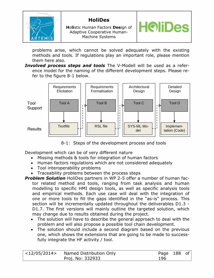
HoliDes
Holistic Human Factors Design of
Adaptive Cooperative Human-
Machine Systems
<12/05/2014> Named Distribution Only
Proj. No: 332933
Page 188 of
196
problems arise, which cannot be solved adequately with the existing
methods and tools. If regulations play an important role, please mention them here also.
Involved process steps and tools The V-Modell will be used as a refer-
ence model for the naming of the different development steps. Please re-
fer to the figure 8-1 below.
Identified Problems will summarize the problems faced in the actual de
Development which can be of very different nature
Missing methods & tools for integration of human factors Human factors regulations which are not considered adequately Tool interoperability problems
Traceability problems between the process steps Problem Solution HoliDes partners in WP 2-5 offer a number of human fac-
tor related method and tools, ranging from task analysis and human modelling to specific HMI design tools, as well as specific analysis tools
and empirical methods. Each use case will deal with the integration of one or more tools to fill the gaps identified in the “as-is” process. This
section will be incrementally updated throughout the deliverables D1.3 -
D1.7. The first versions will mainly outline the targeted solution, which
may change due to results obtained during the project.
The solution will have to describe the general approach to deal with the problem and will also propose a possible tool chain development.
The solution should include a second diagram based on the previous
one, which shows the extensions that are going to be made to success-
fully integrate the HF activity / tool.
Requirements Elicitation
Requirements Formalisation
Architectural Design
Detailed Design
Textfile RSL file SYS-ML Mo-del
Implemen-tation (Code) Results
Tool A Tool B Tool C Tool D Tool Support
8-1: Steps of the development process and tools
HoliDes
Holistic Human Factors Design of
Adaptive Cooperative Human-
Machine Systems
<12/05/2014> Named Distribution Only
Proj. No: 332933
Page 189 of
196
At the end of the project the final solution for the use-case should be
briefly evaluated
HoliDes
Holistic Human Factors Design of
Adaptive Cooperative Human-
Machine Systems
<12/05/2014> Named Distribution Only
Proj. No: 332933
Page 190 of
196
9 References
Ahlstrom, V., & Longo, K. (2003). Chapter 2: General design requirements.
In Human factors design standard. US: US Department of Transporta-
tion Federal Aviation Administration Technical Center. Ahlstrom, V., & Longo, K. (2003). Chapter 3: Automation. In Human factors
design standard. US: US Department of Transportation Federal Aviation
Administration Technical Center. Ahlstrom, V., & Longo, K. (2003). Chapter 5: Displays and printers. In Hu-
man factors design standard. US: US Department of Transportation Federal Aviation Administration Technical Center.
Ahlstrom, V., & Longo, K. (2003). ; Chapter 8: Computer-human interface. In Human factors design standard. US: US Department of Transporta-tion Federal Aviation Administration Technical Center.
Ando, N., Nakano, N. & Tohyama, N. (2008). Human-centered design in medical fields. FUJITSU Sci. Tech. J., 45 (2), 232-238.
ANSI/AAMI HE48-1993 (1993). Human factors engineering guidelines and
preferred practices for the design of medical devices. Association for the Advancement of Medical Instrumentation.
Backhaus, C. (2010). Usability Engineering in der Medizintechnik. Berlin:
Springer-Verlag. BASt (2012) Legal consequences of an increase in vehicle automation; Bun-
desanstalt für Straßenwesen. Block Jr, F. E. (1994). Human factors and alarms. In Clinical Monitoring for
Anaesthesia & Intensive Care (11-34). Philadelphia: WB Saunders. Booher, H. R. (2003). Handbook of human systems integration. Hoboken:
John Wiley and Sons, Inc.
Carsten, O.M.J., Merat, N., Janssen, W.H., Johansson, E. , Fowkes, M.,
Brookhuis, K.A. (2005). HASTE Final Report: Human Machine Interaction
and the Safety of Traffic in Europe Driver Focus-Telematics Working Group (2006). Statement of Principles, Cri-
teria and Verification Procedures on Driver Interactions with Advanced
In-Vehicle Information and Communication Systems. EASA (2012). Certification Specifications for Large Aeroplanes CS-25; AMC
Acceptable Means of Compliance - Subpart F; AMC 25.1302 Installed
systems and equipment for Use by the flight crew; European Aviation
Safety Agency.

HoliDes
Holistic Human Factors Design of
Adaptive Cooperative Human-
Machine Systems
<12/05/2014> Named Distribution Only
Proj. No: 332933
Page 191 of
196
EASA (2012). Certification Specifications for Large Aeroplanes CS-25; Sub-
part F – Equipment; CS 25.1301 Function and installation; European Aviation Safety Agency.
EASA (2012). Certification Specifications for Large Aeroplanes CS-25; Sub-
part F – Equipment; CS 25.1302 Installed systems and equipment for
use by the flight crew; European Aviation Safety Agency. EASA (2012). Certification Specifications for Large Aeroplanes CS-25; Sub-
part F – Equipment; CS 25. 1309 Equipment, systems and installations;
European Aviation Safety Agency. EASA (2012). NPA 2012-02: Airworthiness and operational criteria for the
approval for Electronic Flight Bags; European Aviation Safety Agency.
Edworthy, J. (1994). Urgency mapping in auditory warning signals. In Stan-ton, N., Human Factors in alarm design. London: Taylor and Francis.
Engel, D., & Curio, C. (2013). Detectability Prediction for Increased Scene Awareness; IEEE Intell. Transport. Syst. Mag. 5(4):146-157
(EU) No 347/2012 (2012). Commission Regulation for certain categories of motor vehicles with regard to advanced emergency braking systems. European Union Commission.
(EU) No 351/2012 (2012). Commission Regulation for installation of lane de-
parture warning systems in motor vehicles. European Union Commis-sion.
EUROCONTROL (2007). The Human Factors Case: Guidance for Human Fac-tors Integration (Ed. 2). European Organisation for the Safety of Air Navigation
EUROCONTROL (2009). CREDOS – Human Factors Case Report. European Organisation for the Safety of Air Navigation.
FAA (2012). AC-120-76B: Guidelines for the Certification, Airworthiness, and Operational Use of Electronic Flight Bags; Federal Aviation Administra-
tion. FAA (2003). DOT-VNTSC-FAA-03-07: Human Factors Considerations in the
Design and Evaluation of Electronic Flight Bags; Federal Aviation Admin-
istration
FHWA (2004). In-Vehicle Display Icons and Other Information Elements.
Volume I: Guidelines, Volume II Final Report; U.S. Department of Transportation. Federal Highway Administration.
Ginsburg, G. (2005). Human Factors Engineering: A Tool for Medical Device
Evaluation in Hospital Procurement Decision Making. Journal of Biomed-
ical Informatics, 38, 213-219.

HoliDes
Holistic Human Factors Design of
Adaptive Cooperative Human-
Machine Systems
<12/05/2014> Named Distribution Only
Proj. No: 332933
Page 192 of
196
Gosbee, J. (2004). Introduction to the human factors engineering series.
Joint Commission Journal on Quality and Safety, 30 (4), 215-219. Hansman, R. J., Kuchar, J. K., Clarke, J.-P., Vakil, S., Barhydt, R. & Pritchett,
A. (1997). Integrated human centered systems approach to the devel-
opment of advanced cockpit and air traffic management systems. In
Digital Avionics Systems Conference, 1997. 16th DASC., AIAA/IEEE (pp. 3-6). Irvine,CA.
Honeywell (2012). Electronic Flight Bag Application Design Assessment.
ICAO (2004). Annex 8; Part IIIB. Aeroplanes over 5700 kg for which applica-tion for certification was submitted on or after 2. march 2004; Sub-Part
D. Design and Construction; D1 General; International Civil Aviation Or-
ganisation ICAO (2004). Annex 8; Annex 8; Part IIIB. Aeroplanes over 5700 kg for
which application for certification was submitted on or after 2. march 2004; Sub-Part D. Design and Construction;; D2 Systems Design fea-
tures; International Civil Aviation Organisation IEC 60601-1-6 (2010). General requirements for basic safety and essential
performance. Collateral standard: Usability. IEC International Electro-
technical Commission.
IEC 60601-1-8 (2012). General requirements for basic safety and essential performance. Collateral standard: General requirements, tests and guid-
ance for alarm systems in medical electrical equipment and medical electrical systems. IEC International Electrotechnical Commission.
IEC 60601-2-33 (2013). Particular requirements for basic safety and essen-
tial performance of magnetic resonance equipment for medical diagno-sis. IEC International Electrotechnical Commission.
IEC 60601-2-43 (2010). Particular requirements for basic safety and essen-tial performance of X-ray equipment for interventional procedures. IEC
International Electrotechnical Commission. IEC 62366 (2007). Medical devices: Application of usability engineering to
medical devices. IEC International Electrotechnical Commission.
ISO 9241 (1999-2013). Ergonomics of human-system interaction. DIN Deut-
sches Institut für Normung e.V..
ISO 9241-11 (1999). Ergonomic requirements for office work with visual dis-play terminals (VDTs) – Part 11: Guidance on usability. DIN Deutsches
Institut für Normung e.V..
ISO 9241-20 (2009). Ergonomics of human-system interaction – Part 20:
Accessibility guidelines for information/communication technology (ICT).
DIN Deutsches Institut für Normung e.V..

HoliDes
Holistic Human Factors Design of
Adaptive Cooperative Human-
Machine Systems
<12/05/2014> Named Distribution Only
Proj. No: 332933
Page 193 of
196
ISO 9241-110 (2008). Ergonomics of human-system interaction – Part 110:
Dialogue principles. DIN Deutsches Institut für Normung e.V.. ISO 9241-143 (2012). Ergonomics of human-system interaction – Part 143:
Forms. DIN Deutsches Institut für Normung e.V..
ISO 9241-154 (2013). Ergonomics of human-system interaction – Part 154:
Interactive voice response (IVR) applications. DIN Deutsches Institut für Normung e.V..
ISO 9241-210 (2011). Ergonomics of human-system interaction – Part 210:
Human-centered design for interactive systems. DIN Deutsches Institut für Normung e.V..
ISO 9241-303 (2012). Ergonomics of human-system interaction – Part 303:
Requirements for electronic visual displays. DIN Deutsches Institut für Normung e.V..
ISO 9241-304 (2009). Ergonomics of human-system interaction – Part 304: User performance test methods for electronic visual displays. DIN
Deutsches Institut für Normung e.V.. ISO 9241-305 (2009). Ergonomics of human-system interaction – Part 305:
Optical laboratory test methods for electronic visual displays. DIN
Deutsches Institut für Normung e.V..
ISO 9241-306 (2009). Ergonomics of human-system interaction – Part 306: Field assessment methods for electronic visual displays. DIN Deutsches
Institut für Normung e.V.. ISO 9241-307 (2009). Ergonomics of human-system interaction – Part 307:
Analysis and compliance test methods for electronic visual displays. DIN
Deutsches Institut für Normung e.V.. ISO 9241-400 (2007). Ergonomics of human-system interaction – Part 400:
Principles and requirements of physical input devices. DIN Deutsches In-stitut für Normung e.V..
ISO 9241-410 (2012). Ergonomics of human-system interaction – Part 410: Design criteria for physical input devices. DIN Deutsches Institut für
Normung e.V..
ISO 9241-420 (2011). Ergonomics of human-system interaction – Part 420:
Selection of physical input devices. DIN Deutsches Institut für Normung
e.V.. ISO 11064-1 (2001). Principles for the design of control centres; DIN
Deutsches Institut für Normung e.V.
ISO 11064-2 (2001). Principles for the arrangement of control suites; DIN
Deutsches Institut für Normung e.V.
HoliDes
Holistic Human Factors Design of
Adaptive Cooperative Human-
Machine Systems
<12/05/2014> Named Distribution Only
Proj. No: 332933
Page 194 of
196
ISO 11064-3 (2000). Control room layout; DIN Deutsches Institut für Nor-
mung e.V. ISO 11064-4 (2004). Layout and dimensions of workstations; DIN Deutsches
Institut für Normung e.V.
ISO 11064-5 (2008) Displays and controls; DIN Deutsches Institut für Nor-
mung e.V. ISO 11064-5 (2005) Environmental requirements for control centres; DIN
Deutsches Institut für Normung e.V.
ISO 11064-7 (2006) Principles for the evaluation of control centres; DIN Deutsches Institut für Normung e.V.
ISO 15005 (2012). Road vehicles – Ergonomic aspects of transport infor-
mation and control systems – Dialogue management principles and compliance procedures. DIN Deutsches Institut für Normung e.V..
ISO 15006 (2012). Road vehicles – Ergonomic aspects of transport infor-mation and control systems – Specifications for in-vehicle auditory
presentation. DIN Deutsches Institut für Normung e.V.. ISO 15007 (2002). Road vehicles – Measurement of driver visual behavior
with respect to transport information and control systems. CEN Europe-
an Committee for Standardization.
ISO 15008 (2011). Road vehicles – Ergonomic aspects of transport infor-mation and control systems – Specifications and test procedures for in-
vehicle visual presentation. DIN Deutsches Institut für Normung e.V.. ISO 17287 (2003). Road vehicles: Ergonomic aspects of transport infor-
mation and control systems – Procedure for assessing suitability for use
while driving. DIN Deutsches Institut für Normung e.V.. ISO 26262 (2011). Road vehicles: Funktional Satety; DIN Deutsches Institut
für Normung e.V. IST (2004-2008). Multiple Reports from the AIDE (Adaptive Integrated Driv-
er-Vehicle Interface)-Project; Information Society Technologies Pro-gramme/AIDE-Project
Kaye, R. & Crowley, J. (2000). Medical device use-safety: incorporating hu-
man factors engineering into risk management – identifying, under-
standing and addressing use-related hazards. U.S. Department of Health
and Human Services Food and Drug, Administration Center for Devices and Radiological Health, Division of Device User Programs and Systems
Analysis, Office of Health and Industry Programs.
Knapp, A.; Neumann, M.; Brockmann, M.; Walz, R.; Winkle, T. (2009). Code
of Practice for the Design and Evaluation of ADAS (CoP)

HoliDes
Holistic Human Factors Design of
Adaptive Cooperative Human-
Machine Systems
<12/05/2014> Named Distribution Only
Proj. No: 332933
Page 195 of
196
Kushniruk, A. W. (2002). Evaluation in the design of health information sys-
tems: application of approaches emerging from usability engineering. Computers in Biology and Medicine, 32, 141-149.
Kushniruk, A. W. & Patel, V. L. (2004). Cognitive and usability engineering
methods for the evaluation of clinical information systems. Journal of
Biomedical Informatics, 37, 56-76. Lin, L., Vicente, K.J. & Doyle, D.J. (2001). Patient safety, potential adverse
drug events, and medical device design: a human factors engineering
approach. Journal of Biomedical Informatics, 34, 274-284. NATO (2010). Human Systems Integration for Network Centric Warfare .
NATO RTO Technical Report TR-HFM-155.
NHTSA (2013). Distraction Detection and Mitigation Through Driver Feed-back; National Highway Traffic Safety Administration.
NHTSA (2007). DOT HS 810 697: Crash Warning System Interfaces: Human Factors Insights and Lessons Learned; U.S. Department Of Transporta-
tion. National Highway Traffic Safety Administration. Salvucci, D. D. (2006). Modeling driver behavior in a cognitive architecture.
Human Factors, 48, 362-380.
US Air Force (2009). Air Force Human Systems Integration Handbook. Plan-
ning and Execution of Human Systems Integration. Directorate of Hu-man Performance Integration – Human Performance Optimization Divi-
sion. U.S. Department Of Defense (1995). MIL-HDBK-759C: Handbook for human
engineering design guidelines; U.S. Department Of Defense
U.S. Department Of Defense (2012). MIL-STD-1472G: Design criteria stand-ard – Human engineering; U.S. Department Of Defense
U.S. Department of Health and Human Services Food and Drug Administra-tion (2011). Applying Human Factors and Usability Engineering to Opti-
mize Medical Device Design. U.S. Department of Health and Human Services, Food and Drug Administration, Center for Devices and Radio-
logical Health, Office of Device Evaluation.

HoliDes
Holistic Human Factors Design of
Adaptive Cooperative Human-
Machine Systems
<12/05/2014> Named Distribution Only
Proj. No: 332933
Page 196 of
196
10 List of figures
4-1: HoliDes-RTP-Operational-Capabilities [NSV-01 Resource Interaction
Spec.] ............................................................................................. 56
4-2: Human Views along the V-Model ................................................... 58
4-3: HoliDes-RTP-AdCoS-Design [NSV-01 Resource Interaction Spec.] ..... 61
4-4: SoS-HoliDes-LDM [NOV-07 Information Model] ............................... 64
4-5: SoS-HoliDes-Use-Case-Interaction [NOV-07 Information Model] activities .......................................................................................... 65
6-1: Phases of COP development process ............................................ 115
6-2: Architectural scheme of controllability .......................................... 116
6-3: Creation of an ACT-R model ........................................................ 127
6-4: Testing of researchers’ assumption embodied in the ACT-R model .... 128
6-5: ACT-R architecture .................................................................... 129
8-1: Steps of the development process and tools ................................. 188