review a practical guide for pipeline construction inspectors
TRANSCRIPT

© 2016 CEPA Foundation Inc. and INGAA Foundation Inc.
A Practical Guide for Pipeline Construction Inspectors Published March 2016

Page 2 of 131

Page 3 of 131
ACKNOWLEDGEMENTS
This document was developed through the generous and continual support of all CEPA Foundation and INGAA Foundation members.
CEPA Foundation Executive Director:
Kim McCaig, MBA (CEPA Foundation)
CEPA Foundation Body of Knowledge Subcommittee:
David Montemurro (TransCanada Corp.)
CEPA Foundation Pipeline Inspector Certification Committee Chair:
Jason Landa (JSG Professional Services ULC, a Johnson Service Group Company)
CEPA Foundation Certification Subcommittee:
Andy Duncan, P.Eng. (Enbridge Inc.)
INGAA Foundation Executive Director:
Richard Hoffmann, MSCE (INGAA Foundation)
INGAA Foundation Sponsor & Subcommittee Chair for Pipeline Inspector Certification:
David Montemurro (TransCanada Corp.)
INGAA Foundation Certification Subcommittee Chair:
Andy Duncan, P.Eng. (Enbridge Inc.)
INGAA Foundation Subcommittee Chair for Development of A Practical Guide for Pipeline Construction Inspectors:
Pierre Bigras, P.Eng. (Pacific Gas and Electric Company)
Working Group Members:
Thomas Anderson (Henkels & McCoy, Inc.) Pierre Bigras, P.Eng. (Pacific Gas and Electric Company)
Scott Culley (CDI Corp.) Victor R. Flores Jr., P.E. (Enable Midstream Partners, LP)
Bryon D. Gaskin (Spectra Energy Corp.) Jason Landa (JSG Professional Services ULC, a Johnson Service Group Company)
Roger Lemieux (TransCanada Corp.) Kirk Peterman (Energy Transfer Partners, LP) Joseph Prine (The Williams Companies, Inc.)
Andy Purves, P.Eng. (Stantec Inc.) Ritch Rappel, MBA (Enbridge Inc.)
Bill Watts, P.Eng. (Alliance Pipeline Ltd.)
In collaboration with PBoK Technical Training Ltd.:
Simon van Leeuwen Reena Sahney, P.Eng.
Annie Sio

Page 4 of 131

Page 5 of 131
Table of Contents
ACKNOWLEDGEMENTS ............................................................................................................. 3
1.0 Introduction ........................................................................................................................ 9
2.0 Purpose ............................................................................................................................. 9
3.0 Scope ................................................................................................................................. 9
4.0 Revisions to this Document ............................................................................................. 10
5.0 How to Use this Document .............................................................................................. 10
6.0 Pipeline Construction Inspector – Foundational Information ........................................... 11
6.1 Authority ............................................................................................................... 13
6.2 Code of Conduct .................................................................................................. 13
6.3 Worker, Site, and Construction Safety ................................................................. 14
6.4 Quality, Deficiencies, and Non-conformance Procedures .................................... 15
6.4.1 Escalation Processes ............................................................................................ 16
6.4.2 Personal Violations ............................................................................................... 16
6.5 Environmental Considerations ............................................................................. 17
6.6 Execution of Work ................................................................................................ 18
6.7 Administration of Contractual Obligations ............................................................ 19
6.8 Records Management .......................................................................................... 21
6.9 Personnel Qualifications and Certifications .......................................................... 22
6.10 Equipment Calibration .......................................................................................... 22
6.11 Incident Reporting ................................................................................................ 22
References – Foundational Information ........................................................................... 23
7.0 Survey .............................................................................................................................. 25
7.1 Overview .............................................................................................................. 25
7.2 Inputs ................................................................................................................... 25
7.3 Execution ............................................................................................................. 25
7.4 Outputs ................................................................................................................. 26
Detailed Checklists – Surveying ...................................................................................... 27
7.5 Typical Input Requirements for Survey Inspection ............................................... 27
7.6 Best Practice Items for Inspecting Typical Surveying Operations ........................ 28
7.7 Typical Outputs for Survey Inspection ................................................................. 32
References – Survey ....................................................................................................... 32
8.0 Clearing and Grading ....................................................................................................... 33
8.1 Overview .............................................................................................................. 33
8.2 Inputs ................................................................................................................... 33
8.3 Execution ............................................................................................................. 33

Page 6 of 131
8.4 Outputs ................................................................................................................. 35
Detailed Checklists – Clearing and Grading .................................................................... 36
8.5 Typical Input Requirements for Clearing and Grading Inspection ........................ 36
8.6 Best Practice Items for Inspecting Typical Clearing and Grading Operations ..... 37
8.7 Typical Outputs for Clearing and Grading Inspection .......................................... 43
References – Clearing and Grading ................................................................................ 44
9.0 Stockpiling and Stringing ................................................................................................. 45
9.1 Overview .............................................................................................................. 45
9.2 Inputs ................................................................................................................... 45
9.3 Execution ............................................................................................................. 45
9.4 Outputs ................................................................................................................. 46
Detailed Checklists – Stockpiling and Stringing ............................................................... 47
9.5 Typical Inputs for Stringing and Stockpiling Inspection ........................................ 47
9.6 Best Practices for Typical Stringing and Stockpiling Inspection ........................... 48
9.7 Typical Outputs for Stockpiling and Stringing Inspection ..................................... 52
References – Stockpiling and Stringing ........................................................................... 53
10.0 Field Bending ................................................................................................................... 55
10.1 Overview .............................................................................................................. 55
10.2 Inputs ................................................................................................................... 55
10.3 Execution ............................................................................................................. 55
10.4 Outputs ................................................................................................................. 56
Detailed Checklists – Field Bending ................................................................................ 57
10.5 Typical Input Requirements for Field Bending Inspection .................................... 57
10.6 Best Practice Items for Inspecting Typical Field Bending Operations .................. 58
10.7 Typical Outputs for Field Bending Inspection ....................................................... 59
References – Field Bending ............................................................................................ 60
11.0 Ditching and Excavation .................................................................................................. 61
11.1 Overview .............................................................................................................. 61
11.2 Inputs ................................................................................................................... 61
11.3 Execution ............................................................................................................. 62
11.4 Outputs ................................................................................................................. 63
Detailed Checklists – Ditching and Excavation ................................................................ 64
11.5 Typical Input Requirements for Ditching and Excavation Inspection ................... 64
11.6 Best Practice Items for Inspecting Typical Ditching and Excavation Operations . 65
11.7 Typical Outputs for Ditching and Excavation Inspection ...................................... 70
References – Ditching and Excavation ............................................................................ 70

Page 7 of 131
12.0 Welding ............................................................................................................................ 71
12.1 Overview .............................................................................................................. 71
12.2 Inputs ................................................................................................................... 71
12.3 Execution ............................................................................................................. 71
12.4 Outputs ................................................................................................................. 72
Detailed Checklists – Welding ......................................................................................... 73
12.5 Typical Input Requirements for Welding Inspection ............................................. 73
12.6 Best Practice Items for Inspecting Typical Welding Operations ........................... 74
12.7 Typical Outputs for Welding Inspection ................................................................ 75
References – Welding ..................................................................................................... 76
13.0 Coating ............................................................................................................................ 77
13.1 Overview .............................................................................................................. 77
13.2 Inputs ................................................................................................................... 77
13.3 Execution ............................................................................................................. 77
13.4 Outputs ................................................................................................................. 78
Detailed Checklists – Coating .......................................................................................... 79
13.5 Typical Input Requirements for Coating Inspection ............................................. 79
13.6 Best Practice Items for Inspecting Typical Coating Operations ........................... 80
13.7 Typical Outputs for Coating Inspection ................................................................ 82
References – Coating ...................................................................................................... 83
14.0 Lowering-In ...................................................................................................................... 85
14.1 Overview .............................................................................................................. 85
14.2 Inputs ................................................................................................................... 85
14.3 Execution ............................................................................................................. 85
14.4 Outputs ................................................................................................................. 86
Detailed Checklists – Lowering-In ................................................................................... 87
14.5 Typical Inputs for Lowering-In Inspection ............................................................. 87
14.6 Best Practice Items for Inspecting Typical Lowering-In Operations ..................... 88
14.7 Typical Outputs for Lowering-In Inspection .......................................................... 92
References – Lowering-In ................................................................................................ 92
15.0 Backfilling ......................................................................................................................... 93
15.1 Overview .............................................................................................................. 93
15.2 Inputs ................................................................................................................... 93
15.3 Execution ............................................................................................................. 93
15.4 Outputs ................................................................................................................. 94
Detailed Checklists – Backfilling ...................................................................................... 95
15.5 Typical Inputs for Backfilling Inspection ............................................................... 95

Page 8 of 131
15.6 Best Practice Items for Inspecting Typical Backfilling Operations ....................... 96
15.7 Typical Outputs for Backfilling Inspection .......................................................... 101
References – Backfilling ................................................................................................ 102
16.0 Cathodic Protection ....................................................................................................... 103
16.1 Overview ............................................................................................................ 103
16.2 Inputs ................................................................................................................. 103
16.3 Execution ........................................................................................................... 103
16.4 Outputs ............................................................................................................... 104
Detailed Checklists – Cathodic Protection ..................................................................... 105
16.5 Typical Input Requirements for Cathodic Protection Inspection ........................ 105
16.6 Best Practice Items for Inspecting Typical Cathodic Protection Operations ...... 106
16.7 Typical Outputs for Cathodic Protection Inspection ........................................... 108
References – Cathodic Protection ................................................................................. 109
17.0 Hydrostatic Testing ........................................................................................................ 111
17.1 Overview ............................................................................................................ 111
17.2 Inputs ................................................................................................................. 111
17.3 Execution ........................................................................................................... 111
17.4 Outputs ............................................................................................................... 113
Detailed Checklists – Hydrostatic Testing ..................................................................... 114
17.5 Typical Input Requirements for Hydrostatic Testing Inspection ......................... 114
17.6 Best Practice Items for Inspecting Typical Hydrostatic Testing Operations ....... 116
17.7 Typical Outputs for Hydrostatic Testing Inspection ............................................ 122
References – Hydrostatic Testing .................................................................................. 122
18.0 Clean-up and Restoration .............................................................................................. 123
18.1 Overview ............................................................................................................ 123
18.2 Inputs ................................................................................................................. 123
18.3 Execution ........................................................................................................... 123
18.4 Outputs ............................................................................................................... 124
Detailed Checklists – Clean-up and Restoration ........................................................... 125
18.5 Typical Input Requirements for Clean-up and Restoration Inspection ............... 125
18.6 Best Practice Items for Inspecting Typical Clean-up and Restoration Operations 126
18.7 Typical Outputs for Clean-up and Restoration Inspection Reporting ................. 130
References – Clean-up and Restoration ....................................................................... 130
ENDNOTE ................................................................................................................................. 131

Page 9 of 131
1.0 INTRODUCTION
This guide provides the details related to the role of the Owner Company’s Pipeline Construction Inspector (“Inspector”), in terms of monitoring and inspection requirements throughout the lifecycle of the pipeline construction process. This document is written to address general inspection duties. Areas of specialty inspection are noted and are beyond the scope of this document. This document represents best practices based on the accumulated experience and consensus amongst the majority of member companies in terms of technical requirements, both in Canada and the U.S., for pipeline construction inspection competencies and related tasks beyond those captured in regulation and current certification. With the anticipated increase in upcoming pipeline construction activity, the CEPA (Canadian Energy Pipeline Association) and INGAA Foundations have established a Pipeline Inspector Certification Working Group as part of meeting a number of key objectives that include:
Introducing a fundamental step change in the training and qualification of Pipeline Construction Inspectors as a means of improving the construction quality of projects
Improving the overall quality of work performed by Pipeline Construction Inspectors within the industry
This document, in particular, is intended to support some of these broader objectives by establishing a meaningful reference tool to enhance learning for the Pipeline Construction Inspector as a complement to the existing industry knowledge base and documentation (such as recognition and alignment with the American Petroleum Institute Recommended Practice for Basic Inspection Requirements — New Pipeline Construction (API 1169), Canadian Welding Bureau (CWB), American Welding Society (AWS), and NACE International).
2.0 PURPOSE
The purpose of this document is to provide Pipeline Construction Inspectors with background and context, beyond existing regulation, regarding best practices in the industry. As such, this document is not intended to replace formal training, regulation, or Company specific practices (which may vary based on individual circumstances); rather, it is intended as a complementary guide to information from those sources.
3.0 SCOPE
The scope of this document is limited to gas and liquid pipeline construction. Specifically, content is focused on those items that are relevant to the role of a Pipeline Construction Inspector as it relates to best practices within the industry.

Page 10 of 131
4.0 REVISIONS TO THIS DOCUMENT
This document will be reviewed periodically (as per existing CEPA and INGAA Foundation practices) to ensure the content within remains relevant and accurate. However, it remains the responsibility of the user to ensure that the most current revision of documents (e.g., codes and standards) are referenced, where appropriate.
5.0 HOW TO USE THIS DOCUMENT
With an eye to practicality and ease of use, this document is organized to reflect the typical construction process for transmission pipelines. Foundational information common to all aspects of construction is presented first, followed by chapters specific to each phase of construction. Within each chapter, five main headings are used consistently:
Overview – a brief description of the specific activities in the construction phase
Inputs – detailed information regarding typical information the Inspector will require
Execution – detailed information regarding items the Inspector should typically watch for; for ease of use, items are typically formulated as actions using verbs such as: ensure, monitor, confirm, check, etc.
Outputs – detailed information listing typical information the Inspector will be required to produce for the Owner Company
References – list of key relevant reference documents for those seeking additional information for each phase of construction
The “Inputs” section within each chapter is intended to clearly identify the types of documents, specifications, and other information the Inspector would likely need to reference in that phase of construction. The “Execution” section within each chapter provides detailed checklists, often grouped by major topic, identifying critical items that Inspectors should monitor in that construction phase. Finally, the “Output” section within each chapter then articulates items that the Inspector is expected to produce or report on as it relates to that particular phase of the construction project. The use of the word “ensure” throughout this document is intended to convey that Inspectors “ensure” that the contractor has performed the inspected work properly through observing, monitoring, assessing, evaluating, verifying, deciding, resolving, reporting, and documenting to ensure that the project requirements are met.

Page 11 of 131
6.0 PIPELINE CONSTRUCTION INSPECTOR – FOUNDATIONAL INFORMATION
The items covered in this chapter are those that are relevant through all phases of the pipeline construction process (see Figure 1). As such, any specific content in other chapters of this publication is intended to be used in conjunction with the information provided within this section. Additional information regarding the pipeline construction process can be found in the INGAA Foundation publication “Building Interstate Natural Gas Transmission Pipelines: A Primer”. The Inspector acts as the Owner Company’s authorized representative for non-financial matters, continuously observes the Contractor’s progress and monitors all activities in their assigned areas in accordance with codes and standards; regulatory requirements; Owner Company safety and environmental requirements, drawings, plans, and specifications; as well as the terms of the construction contract or agreement. The Inspector may also be asked to assist other specialized Inspectors (e.g., Welding Inspector), as directed. In addition to executing specific responsibilities in the following chapters, the Inspector has key responsibilities in the main areas identified in Table 1 with additional detail provided in the corresponding section.
Table 1: Main Areas of Inspector Roles and Responsibilities
Topic Area Section Number
Authority Section 6.1
Code of Conduct Section 6.2
Worker, Site, and Construction Safety Section 6.3
Quality, Deficiencies, and Non-conformance Procedures Section 6.4
Environmental Considerations Section 6.5
Execution of Work Section 6.6
Administration of Contractual Obligations Section 6.7
Records Management Section 6.8
Personnel Qualifications and Certifications Section 6.9
Equipment Calibration Section 6.10
Incident Reporting Section 6.11

Page 12 of 131
Figure 1: Typical Pipeline Construction Phases
Survey
Clearing & Grading
Stockpiling & Stringing
Field Bending
Ditching & Excavation
Welding
Coating
Lowering-In
Backfilling
Cathodic Protection
Hydrostatic Testing
Clean-up & Restoration

Page 13 of 131
6.1 Authority
The Inspector on-site is part of a larger Project Team; as such, the Inspector should understand their role within the established chain of command and recognize situations that may need to be escalated in the best interests of the Owner Company. This is important not only for day-to-day operations, but becomes particularly important in the handling of deficiencies / non-conformances discussed later in this chapter. In particular:
Roles of the Contractor and Inspector will be established before performing the tests or measurements to determine whether the work or an item complies with specifications and permit requirements
If the Contractor performs tests or measurements unassisted, the Inspector should be clear about the level of witnessing required, and make sure that the equipment and instruments used by the Contractor are correct and properly calibrated
The Contractor should be aware of the Inspector’s duties and authority (as defined in Section 6.4) outlining quality, deficiencies, and non-conformance procedures
The Inspector has “stop work” authority when there is imminent danger to people or the environment
6.2 Code of Conduct
As the Inspector represents the Owner Company, they should always act ethically, professionally, objectively, consistently, and honestly when performing the required roles and responsibilities. More specifically, the actual ethical conduct required from Inspectors is governed by the Owner Company’s Code of Conduct, which typically includes (but is not limited to) the items identified in Table 2.
Table 2: Typical Code of Conduct Considerations
✓ Description
Behaving in an Ethical Manner
Abide by confidentiality agreements
Not accepting gratuities of any kind that may be perceived to affect judgment in the work being performed as an Inspector; if gratuities are offered, this information should be reported to the Owner Company
Endeavor to be fair, reasonable, and objective towards performing work requirements at all times
Do not make assumptions; consult with the Construction Manager / Chief Inspector (or designate) if there are uncertainties in the requirements
Accept or reject the work performed by the Contractor based on the quality of the work
Comply with all relevant codes, standards, systems, permits, contracts, agreements, specifications, procedures, approved drawings, line lists
Document all deviations and when required, escalate in an appropriate manner for approval
Professional Approach to Work
Be knowledgeable of and understand the relevant parts of the construction process

Page 14 of 131
✓ Description
Be knowledgeable of and understand Owner Company’s standards and specifications
Be knowledgeable of and understand relevant industry and government standards
Ensure all applicable permits required to execute the work are in place and on-site prior to commencing the work
Uphold Owner Company’s industry practices to ensure safety, minimize risk, and avoid hazards in the workplace
Comply with Owner Company’s construction timelines and understand Owner Company’s construction schedule, costs, and components of the work
Understand the role relative to other Stakeholders in the construction process and engage other expertise accordingly
Make accurate decisions by being well informed and familiar with all contract documents and design requirements
Arrive on site before the Contractor’s crew and remain until after the crew leaves the site for the day
Take breaks when the Contractor’s crew takes breaks and remain on site during construction activities that require inspection
Obtain all applicable documents before the start of inspection
If questions arise that cannot be answered, seek those that have the authority to resolve
Be proactive in problem solving and raise issues/concerns to the attention of the Construction Manager / Chief Inspector (or designate)
Positive Image in Representation of Owner Company
Behave in a courteous manner
Conduct oneself in a respectable manner during off-time hours
Show respect through good driving habits on the right of way (ROW) or public roads
Check the work area for good housekeeping and tidiness (e.g., equipment and consumables should be correctly handled, stored, and maintained)
6.3 Worker, Site, and Construction Safety
One of the key roles of the Inspector is to assist the Owner Company in ensuring a safe work environment both for its workers as well as the public. As such, all on-site Inspectors have “stop work” authority should a safety situation arise. In addition to safety items detailed in the following chapters, the Inspector should keep in mind the items identified in Table 3.
Table 3: Typical Safety Considerations
✓ Description
General
Ensure each member of the activity crew understands their role and responsibility with respect to safety in the execution of the work
Plan, schedule, and administer tailgate meetings prior to commencing safety sensitive work (e.g., tie-ins, excavations requiring shoring, line evacuation, hot cuts)
Be aware of changes in work activities or site conditions that were not identified in the daily tailgate meeting along with any changes to precautions that need to be taken as a result of these changes
Manage a proactive approach to participating in the morning Contractor safety meetings

Page 15 of 131
✓ Description
Promote a safe working environment of continuous improvement through communications of project issues and solutions
Ensure any required emergency medical services are in place
Continuously inspect and monitor the Contractor’s workmanship and ensure conformance to Owner Company’s Health and Safety specifications and Site Specific Safety Plans
Monitor for compliance to safety regulations
Ensure emergency / after-hours contact information is posted in site offices and provided to active Contractors
Continuously monitor for compliance to personal protective equipment (PPE) requirements
Ensure “safety zones” are in place and maintained at powerline locations
Safety Audits
Participate in weekly Project Site Specific Safety Audits and provide a constructive Corrective Action Plan to communicate safety issues to the Contractor
Track and communicate project Safety Site Audit results to all Project Team Members
In support of a safe work environment, the Owner Company’s safety policies typically include (but are not limited to) those identified in Table 4.
Table 4: List of Typical Owner Company Safety Policies / Practices / Procedures
✓ Description
H2S Safety
Working Alone Policy
Fall Protection Practice
Restricted Work Areas Policy
Confined Space Entry Practice
Hearing Conservation Practice
Manual Lifting and Carrying Practice
Lockout / Tag-out Procedure
Vehicle and Equipment Safety Practice
Drug and Alcohol Policy
Job Safety Analysis (JSA)
Other Owner Company or project specific requirements, as applicable
6.4 Quality, Deficiencies, and Non-conformance Procedures
The Pipeline Construction Inspector plays a critical role in managing the quality of work performed during pipeline construction. As such, the Inspector should recognize that inspection requires monitoring to regulation as well as the critical elements of the Owner Company’s quality management system (QMS). Those items that are specifically relevant to the Inspector typically include the items listed in Table 5.

Page 16 of 131
Table 5: List of Typical Owner Company Quality Documentation
✓ Description
QMS Manual
Quality Plan
Inspection and Test Plan (ITP)
Orientation with approved and current Owner Company specific requirements, processes, procedures, contact documents, and drawings relevant to their role
As the Inspector identifies any deviations, Owner Company specific escalation processes will need to be followed.
6.4.1 Escalation Processes
Since the Inspector monitors all pipeline construction activities and operations for safety, stewardship of the environment, as well as compliance to project specifications and pertinent regulations, the Owner Company will have an escalation process in place to deal with any identified deficiencies (an isolated deviation from requirements that does not impact safety, environment, structural integrity, cost, or schedule) that may require elevation to a non-conformance (a recurring deficiency or major deviation from regulation or Owner Company specification such that safety, environment, structural integrity, cost, or schedule could be impacted). Any identified non-conformance(s) need to be addressed through corrective action(s). Specific processes vary from Company to Company and Inspectors will familiarize themselves accordingly; however, all escalation processes will typically be structured as follows:
1. Verbal discussion with Third Party Representative 2. Verbal warning with notification 3. Written warning including signed documentation 4. Stop work that can potentially impact the health, safety and
environment of people working on the worksites, the community, and the land where the work is being conducted
6.4.2 Personal Violations
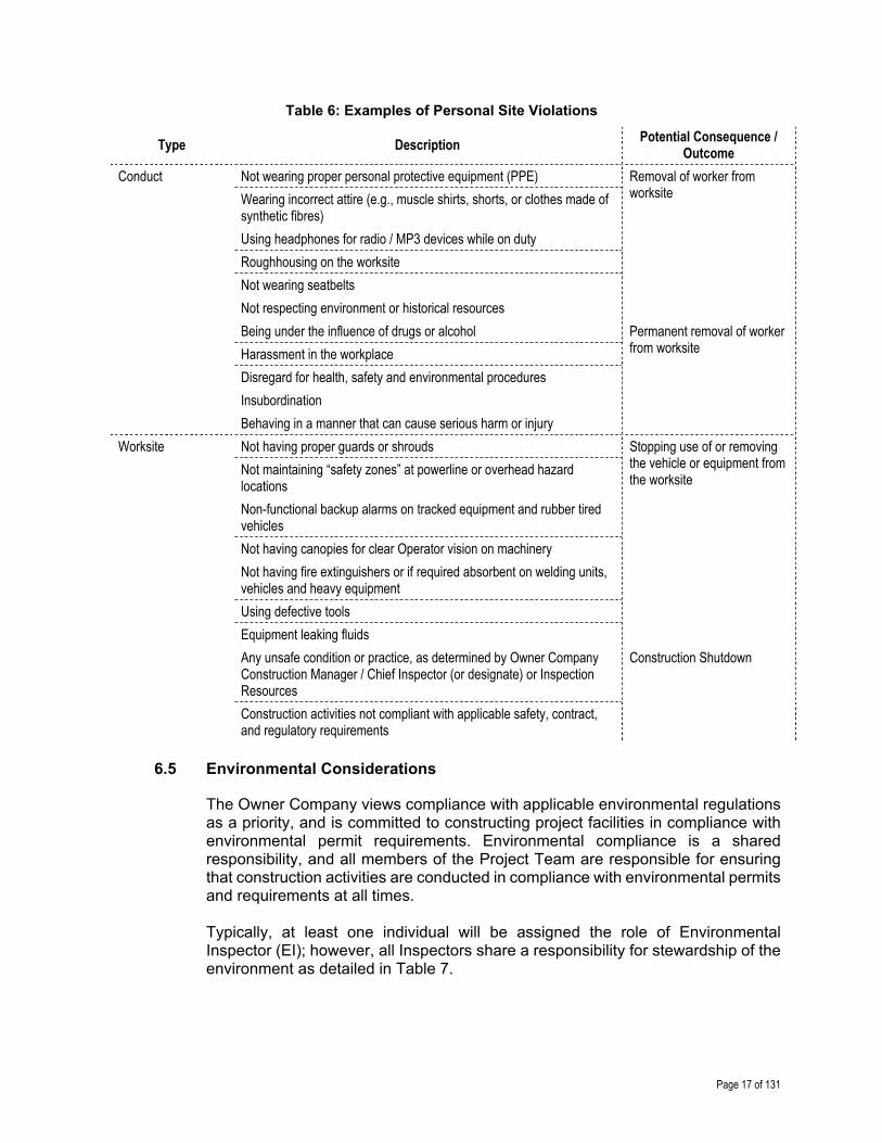
The Inspector should continuously observe and report individuals for personal violations. The typical examples of personal violations are included in (but not limited to) the items identified in Table 6.
Page 17 of 131
Table 6: Examples of Personal Site Violations
Type Description Potential Consequence /
Outcome
Conduct Not wearing proper personal protective equipment (PPE) Removal of worker from worksite Wearing incorrect attire (e.g., muscle shirts, shorts, or clothes made of
synthetic fibres)
Using headphones for radio / MP3 devices while on duty
Roughhousing on the worksite
Not wearing seatbelts
Not respecting environment or historical resources
Being under the influence of drugs or alcohol Permanent removal of worker from worksite Harassment in the workplace
Disregard for health, safety and environmental procedures
Insubordination
Behaving in a manner that can cause serious harm or injury
Worksite Not having proper guards or shrouds Stopping use of or removing the vehicle or equipment from the worksite
Not maintaining “safety zones” at powerline or overhead hazard locations
Non-functional backup alarms on tracked equipment and rubber tired vehicles
Not having canopies for clear Operator vision on machinery
Not having fire extinguishers or if required absorbent on welding units, vehicles and heavy equipment
Using defective tools
Equipment leaking fluids
Any unsafe condition or practice, as determined by Owner Company Construction Manager / Chief Inspector (or designate) or Inspection Resources
Construction Shutdown
Construction activities not compliant with applicable safety, contract, and regulatory requirements
6.5 Environmental Considerations
The Owner Company views compliance with applicable environmental regulations as a priority, and is committed to constructing project facilities in compliance with environmental permit requirements. Environmental compliance is a shared responsibility, and all members of the Project Team are responsible for ensuring that construction activities are conducted in compliance with environmental permits and requirements at all times. Typically, at least one individual will be assigned the role of Environmental Inspector (EI); however, all Inspectors share a responsibility for stewardship of the environment as detailed in Table 7.

Page 18 of 131
Table 7: List of Typical Environmental Activities
✓ Description
Inform and instruct all Employees/Contractors of environmental concerns, special conditions, regulations, and specific permit conditions applicable to the construction area and the work itself
Maintain contact with the Environmental Inspector (EI)
Ensure that disturbance or damage to the environment is minimized, especially the following: Uncontrolled fires Soil and water erosion Habitat damage or loss Air, noise, and water pollution
Ensure construction entrances are maintained to prevent tracking mud and debris onto public roadways
In case of unanticipated disturbance or damage caused by construction activities, contact the Environmental Inspector and mitigate as soon as possible to restore affected areas to their original condition (to the extent possible) in a manner satisfactory to the Owner Company, Land Owners, Land Holder, and regulatory authorities
Ensure equipment is not fueled or serviced within specified distances of water bodies
Ensure that hazardous materials are stored away from specified distances of water bodies
Ensure that all construction debris (e.g., rags, oil cans) and garbage is collected and disposed of to an approved facility off the right of way (ROW)
Observe for persons feeding or harassing livestock or wildlife; if observed, report incident immediately to the Construction Manager / Chief Inspector (or designate)
Report all wildlife deaths and nuisance animals to the Environmental Inspector
Observe for firearm possession while on or off the ROW (e.g., at camp); if observed, report incident immediately to the Construction Manager / Chief Inspector (or designate)
Observe for possession of pets while on or off the ROW (e.g., at camp); if observed, report incident immediately to the Construction Manager / Chief Inspector (or designate)
Ensure all specified vehicles have a minimum specified amount of commercial sorbent material to address spills on both water and land
Ensure construction activities avoid interference with the normal flow of water in any natural or man-made watercourse
Ensure Contractor’s personnel have read and understand the environmental specifications and commitments
Ensure all environmentally sensitive material is properly disposed of
Ensure Fire Prevention and Firefighting Plans are updated, including details of monitoring, prevention, and response concerning: ROW preparation Manpower and equipment Training of personnel Emergency procedures
6.6 Execution of Work
As the Inspector acts as the Owner Company’s authorized representative, monitoring the work for conformance to Owner Company specifications is critical for not only meeting site safety and environmental expectations. It is critical for ensuring quality of construction which is necessary for long term safety, environmental, and cost effectiveness of the pipeline asset.

Page 19 of 131
Best practices relevant for each phase of construction are identified in the following chapters in significant detail; however, additional activities that the Inspector will undertake include:
Disseminate and explain Owner Company specifications and project specific documentation to other Inspectors (where required); it is key that the latest construction drawings and specifications are utilized
Advance planning and organization of all construction activities, including: inspection, survey, and radiographic duties; materials availability; tie-ins and service disruptions; and commissioning and start-up
Maintain lines of communication with key Stakeholders as appropriate (including but not limited to):
o Construction Manager / Chief Inspector (or designate) o Contractors and Subcontractors o Land Agents o Third Party Owner Representative (where applicable) o Pipeline System Operations Personnel o Project Engineers
Follow site-specific communications protocol as defined in the project
6.7 Administration of Contractual Obligations
It is part of the Inspector’s role to understand contractual obligations and ensure that the Contractor is carrying out construction activities / operations accordingly. The Inspector’s role in the administration of contractual obligations is summarized in Table 8, and may include the need to understand the types of agreements and contracts issued or applied for by the Owner Company as detailed in Table 9.
Table 8: Inspector Role in Administration of Contractual Agreements
✓ Description
Maintain, coordinate, and communicate progress and schedule updates per Owner Company requirements
Ensure Owner Company agreements (e.g., Crossing agreements, Third Party utilities agreements, Land Owner agreements), based on the line list, are executed
Verify, approve, and forward Contractor work items and materials on a daily basis to the Construction Manager / Chief Inspector (or designate)
Perform material take-off (MTO) and ascertain status of all materials
Obtain approval from Construction Manager / Chief Inspector (or designate) prior to commencing any extra work activities
Ensure only most current revision of Issued for Construction (IFC) drawings, approved contract documents, and specifications are referenced for construction
Ensure that all proposed deviations from specifications, design changes, or material substitutions are discussed and approved by the Construction Manager / Chief Inspector (or designate) prior to proceeding with the work
Communicate lessons learned and foster an environment of continuous improvement, including participating in post-job review meetings

Page 20 of 131
Table 9: Typical Approvals/Contracts Issued or Applied For by Owner Company
Type Description
Agreements Railroad Crossing Agreements – these agreements are needed to cross any operating or abandoned railroad tracks along the proposed pipeline route
Pipeline Crossing Agreements – these agreements are needed to cross any existing operating or abandoned underground and aboveground pipelines along the proposed pipeline route
Utility Crossing Agreements – needed to cross any operating or abandoned underground utilities (e.g., fibre-optics, telephone, or other electrical) along the proposed pipeline route
Power Line Crossing Agreements – needed to cross any overhead power lines along the proposed pipeline route
Road Use Agreements; needed to use applicable public roads during construction to access pipeline construction sites
Road Crossing Agreements – required to construct pipeline under public or private roads during construction along the proposed pipeline route
Land Use Agreement – land use type of agreements, which may include provisions for: o Pipeline Lease Agreement (PLA) o Pipeline Installation Lease Agreement o Pipe Stockpile Site o Camp Site o Approved Working Hours
Permits Regulatory and jurisdictional permits (in some cases some of these would be obtained by the Contractor), which may include: o Work Permits on Crown / Public land o Work Permits on Private land o Fenced Enclosure Permits o Encroachment Permits
Contracts Pipe Stockpiling
Construction Survey
Emergency Medical Service (EMS)
Clearing / Grading
Pipeline, Facility, or Integrity construction activities
Non-destructive Examination (NDE)
Caliper Pigging
Fabrication
Compaction Testing
Trenchless Crossings
Contracts associated with (small) miscellaneous reclamation activities
Page 21 of 131
6.8 Records Management
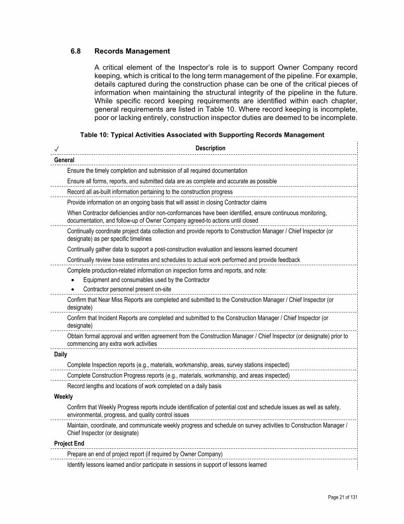
A critical element of the Inspector’s role is to support Owner Company record keeping, which is critical to the long term management of the pipeline. For example, details captured during the construction phase can be one of the critical pieces of information when maintaining the structural integrity of the pipeline in the future. While specific record keeping requirements are identified within each chapter, general requirements are listed in Table 10. Where record keeping is incomplete, poor or lacking entirely, construction inspector duties are deemed to be incomplete.
Table 10: Typical Activities Associated with Supporting Records Management
✓ Description
General
Ensure the timely completion and submission of all required documentation
Ensure all forms, reports, and submitted data are as complete and accurate as possible
Record all as-built information pertaining to the construction progress
Provide information on an ongoing basis that will assist in closing Contractor claims
When Contractor deficiencies and/or non-conformances have been identified, ensure continuous monitoring, documentation, and follow-up of Owner Company agreed-to actions until closed
Continually coordinate project data collection and provide reports to Construction Manager / Chief Inspector (or designate) as per specific timelines
Continually gather data to support a post-construction evaluation and lessons learned document
Continually review base estimates and schedules to actual work performed and provide feedback
Complete production-related information on inspection forms and reports, and note: Equipment and consumables used by the Contractor Contractor personnel present on-site
Confirm that Near Miss Reports are completed and submitted to the Construction Manager / Chief Inspector (or designate)
Confirm that Incident Reports are completed and submitted to the Construction Manager / Chief Inspector (or designate)
Obtain formal approval and written agreement from the Construction Manager / Chief Inspector (or designate) prior to commencing any extra work activities
Daily
Complete Inspection reports (e.g., materials, workmanship, areas, survey stations inspected)
Complete Construction Progress reports (e.g., materials, workmanship, and areas inspected)
Record lengths and locations of work completed on a daily basis
Weekly
Confirm that Weekly Progress reports include identification of potential cost and schedule issues as well as safety, environmental, progress, and quality control issues
Maintain, coordinate, and communicate weekly progress and schedule on survey activities to Construction Manager / Chief Inspector (or designate)
Project End
Prepare an end of project report (if required by Owner Company)
Identify lessons learned and/or participate in sessions in support of lessons learned

Page 22 of 131
6.9 Personnel Qualifications and Certifications
Confirming the qualifications of individuals allowed on site is an important element of ensuring a safe construction operation as well ensuring that the work meets an acceptable level of quality. For example, welding operations have very specific requirements for the qualification of Welders and the work they undertake. These personnel qualifications / certifications are identified in the following chapters where relevant and completed prior to construction unless there are on-site changes. Qualifications and certifications should also comply with applicable regulatory requirements (e.g., Owner Company Operator Qualification (OQ) Plans).
6.10 Equipment Calibration
Often activities during pipeline construction require specialized equipment for measurement. For example, jeeping / holidaying equipment (used to detect coating film discontinuities that may compromise pipe integrity) is a critical part of ensuring long term safety of the pipeline. In these situations, the Inspector will ensure that only properly calibrated test equipment is used on-site and supporting calibration records are available. When required, the Inspector will also confirm that the Contractor’s Operators are properly trained and knowledgeable with application and operation techniques, their equipment, and materials as per Section 6.9.
6.11 Incident Reporting
Should an incident occur, the Inspector is expected to assist the Owner Company (and where necessary, the local authorities) in conducting a formal and objective Incident Report. In particular, the Inspector should keep in mind the items identified in Table 11.
Table 11: Typical Incident Considerations
✓ Description
Take immediate action to ensure injuries are attended to and/or emergency services are contacted
Freeze the work site if required, based on Construction Manager / Chief Inspector (or designate) authority (see Section 6.1)
Immediately report all injuries, vehicle incidents, near misses, and any unsafe conditions to the Construction Manager / Chief Inspector (or designate)
Ensure that site evidence is preserved, pictures are taken, and documentation and witness statements are gathered and retained as soon as practical
Participate in incident investigations (as required)
If site shutdown occurs, obtain authorization from Owner Company when site can be returned to services

Page 23 of 131
References – Foundational Information
Note to user: The reference information provided in Table 12 is intended as a guide only (i.e., the list is not exhaustive); documents of this nature are updated frequently and it remains the responsibility of the user to ensure that the correct, and most current, documents are referenced as appropriate.
Table 12: List of References – Foundational
Document No. Type Title
American Petroleum Institute (API)
API RP 1169 Recommended Practice Recommended Practice for Basic Inspection Requirements – New Pipeline Construction
API Specification Q1 Specification Specification for Quality Management System Requirements for Manufacturing Organizations for the Petroleum and Natural Gas Industry
N/A Effectivity Sheet API 1169 Exam Publication Effectivity Sheet
American Society of Mechanical Engineers (ASME)
ASME B31.4 Standard Pipeline Transportation Systems for Liquids and Slurries
ASME B31.8 Standard Gas Transmission and Distribution Piping Systems
Canadian Federal Regulations
N/A Regulation Canadian Environmental Protection Act
N/A Regulation Fisheries and Oceans – Land Development Guidelines for the Protection of Aquatic Habitat
N/A Regulation Canada Water Act
N/A Regulation Migratory Bird Convention Act
N/A Regulation Canadian Occupational Health and Safety Regulations (COHS)
N/A Regulation Transport Canada – Transportation of Dangerous Goods Regulations
N/A Regulation Navigation Protection Act
N/A Regulation Species at Risk Act
Canadian Standards Association (CSA)
CSA Z662 Standard Oil and Gas Pipeline Systems
Code of Federal Regulations (CFR)
29 CFR Part 172 Regulation Hazardous Materials Table
29 CFR Part 1910 Regulation Occupational Safety and Health Standards
29 CFR Part 1926 Regulation Safety and Health Regulations for Construction
33 CFR Part 321 Regulation Permits for Dams and Dikes in Navigable Waters of the United States
40 CFR Part 300 Regulation National Oil and Hazardous Substances Pollution Contingency Plan
49 CFR Part 192 Regulation Transportation of Natural and Other Gas by Pipeline: Minimum Federal Safety Standards
49 CFR Part 195 Regulation Transportation of Hazardous Liquids by Pipeline

Page 24 of 131
Document No. Type Title
50 CFR Part 21 Regulation Migratory Bird Permits
Federal Energy Regulatory Commission (FERC)
18 CFR380.12 (i) Regulation Upland Erosion Control, Revegetation, and Maintenance Plan
18 CFR380.12(d) Regulation Wetland and Waterbody Construction and Mitigation Procedures
Interstate Natural Gas Association of America (INGAA)
N/A Report Safety Every Step of the Way
INGAA Foundation
Report 2013.01 Report Building Interstate Natural Gas Transmission Pipelines: A Primer
N/A Report Overview of Quality Management Systems – Principles and Practices for Pipeline Construction
N/A Report Construction Safety Consensus Guidelines – Basic Personal Protective Equipment
National Energy Board (NEB)
OPR-99 Regulation Canadian Onshore Pipeline Regulations 1
United States Code (USC)
16 USC Chapter 35 Regulation Endangered Species
33 USC Chapter 9 Regulation Protection of Navigable Waters and of Harbor and River Improvements Generally
Note(s): 1) OPR-99 is the overarching Canadian regulation, but does not include specific instructions for the typical
Pipeline Inspector; rather, it incorporates through reference of other documents that are directly relevant

Page 25 of 131
Survey Clearing & Grading
Stockpiling & Stringing
Field Bending
Ditching & Excavation Welding Coating Lowering-
In Backfilling Cathodic Protection
Hydrostatic Testing
Clean-up & Restoration
7.0 SURVEY
7.1 Overview
Surveying is an integral part of pipeline construction, and refers to the installation of visual reference points and markers (e.g., stakes, pins, lath, and hubs) that will define the right of way (ROW) limits and guide the construction of the pipeline and necessary appurtenances according to the Issued for Construction (IFC) drawings. The references also mark the safe limits of ROW work areas. If the area for the approved pipeline route is forested, Construction Surveyors are commonly the first to arrive to flag trees so Clearing Contractors can cut them down and establish the ROW for pipeline construction. The Inspector is the technical liaison for survey information between the Construction Manager / Chief Inspector (or designate), Survey Contractor, and other on-site Contractors.
7.2 Inputs
As part of preparing for inspection during the surveying process, the Inspector will continually familiarize themselves with relevant aspects of key documents, drawings, and Owner Company technical specifications as identified in Table 14.
7.3 Execution
While the work is being executed, the Inspector is required to monitor workmanship and report on progress on a periodic basis. Typical items that the Inspector will monitor for during the surveying process are identified in a series of checklists as detailed in Table 13.

Page 26 of 131
Survey Clearing & Grading
Stockpiling & Stringing
Field Bending
Ditching & Excavation Welding Coating Lowering-
In Backfilling Cathodic Protection
Hydrostatic Testing
Clean-up & Restoration
Table 13: Monitoring Requirements for Survey Inspection
Item Description Reference
Prior to Commencing Work
On a daily basis, ensure key issues that have been identified are detailed and addressed
Table 15
Safety Monitor the operations for adherence to relevant Owner Company and project specific safety requirements
Table 16
Environmental Considerations
Identifies specific items that should be monitored throughout surveying operations that relate specifically to the Owner Company and/or project specific Environmental Protection Plan (EPP)
Table 17
General Identifies general items that should be monitored throughout the construction surveying process
Table 18
Buried Facilities Location
Identifies specific survey items that should be monitored at buried facilities locations
Table 19
Right of Way (ROW) Identifies specific survey items that should be monitored for at ROW boundaries
Table 20
Ditch Line Identifies specific survey items that should be monitored along the ditch line
Table 21
Crossings Identifies specific survey items that should be monitored at crossing locations (e.g., roads, powerlines)
Table 22
Appurtenances Identifies specific survey items that should be monitored at appurtenance locations
Table 23
As-Builts Identifies specific information that should be monitored for collection in support of completing as-builts
Table 24
Pilings Identifies specific survey items that should be monitored for piling locations
Table 25
Caliper Pigging Identifies specific survey items that should be monitored in support of caliper pig runs
Table 26
7.4 Outputs
The Inspector is required to report on workmanship and progress on a periodic basis (e.g., daily or weekly) by completing various reports on each work day and end of week. Report requirements and reporting processes are Owner Company and project specific; however, best practices for reporting requirements for survey inspection appear in Table 27.

Page 27 of 131
Survey Clearing & Grading
Stockpiling & Stringing
Field Bending
Ditching & Excavation Welding Coating Lowering-
In Backfilling Cathodic Protection
Hydrostatic Testing
Clean-up & Restoration
Detailed Checklists – Surveying
7.5 Typical Input Requirements for Survey Inspection
Table 14: Information Requirements for Survey Inspection
✓ Description
All designs, drawings, and specifications developed by the Owner Company and Contractors related to surveying, such as: Access Road Drawings Line List (e.g., special concerns for each Land Owner) Issued for Construction (IFC) Drawings
Contracts and agreements related to: Road Use Crossing for Buried Facilities Construction Survey Land Owner Agreements Third Party Crossing Agreements
Permits related to: Environmental Road Use Third Party Crossing Permits
Owner Company specific Safety Plan, including (but not limited to): Traffic Control Plan Requirements for Personal Protective Equipment (PPE) Emergency Medical Services (EMS)
Project specific Environmental Protection Plan (EPP) detailing surveying requirements for the following (but not limited to): Watercourses Wetlands, muskeg, and swamp areas Wildlife habitats Migratory routes
Other project specific Plans, which may include: Fire Prevention / Firefighting Plan Survey Plans
Page 28 of 131
Survey Clearing & Grading
Stockpiling & Stringing
Field Bending
Ditching & Excavation Welding Coating Lowering-
In Backfilling Cathodic Protection
Hydrostatic Testing
Clean-up & Restoration
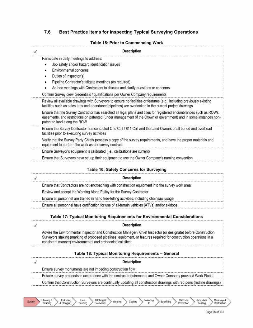
7.6 Best Practice Items for Inspecting Typical Surveying Operations
Table 15: Prior to Commencing Work
✓ Description
Participate in daily meetings to address: Job safety and/or hazard identification issues Environmental concerns Duties of Inspector(s) Pipeline Contractor’s tailgate meetings (as required) Ad-hoc meetings with Contractors to discuss and clarify questions or concerns
Confirm Survey crew credentials / qualifications per Owner Company requirements
Review all available drawings with Surveyors to ensure no facilities or features (e.g., including previously existing facilities such as sales taps and abandoned pipelines) are overlooked in the current project drawings
Ensure that the Survey Contractor has searched all legal plans and titles for registered encumbrances such as ROWs, easements, and restrictions on patented (under management of the Crown or government) and in some instances non-patented land along the ROW
Ensure the Survey Contractor has contacted One Call / 811 Call and the Land Owners of all buried and overhead facilities prior to executing survey activities
Verify that the Survey Party Chiefs possess a copy of the survey requirements, and have the proper materials and equipment to perform the work as per survey contract
Ensure Surveyor’s equipment is calibrated (i.e., calibrations are current)
Ensure that Surveyors have set up their equipment to use the Owner Company’s naming convention
Table 16: Safety Concerns for Surveying
✓ Description
Ensure that Contractors are not encroaching with construction equipment into the survey work area
Review and accept the Working Alone Policy for the Survey Contractor
Ensure all personnel are trained in hand tree-felling activities, including chainsaw usage
Ensure all personnel have certification for use of all-terrain vehicles (ATVs) and/or skidoos
Table 17: Typical Monitoring Requirements for Environmental Considerations
✓ Description
Advise the Environmental Inspector and Construction Manager / Chief Inspector (or designate) before Construction Surveyors staking (marking of proposed pipelines, equipment, or features required for construction operations in a consistent manner) environmental and archaeological sites
Table 18: Typical Monitoring Requirements – General
✓ Description
Ensure survey monuments are not impeding construction flow Ensure survey proceeds in accordance with the contract requirements and Owner Company provided Work Plans Confirm that Construction Surveyors are continually updating all construction drawings with red pens (redline drawings)
Page 29 of 131
Survey Clearing & Grading
Stockpiling & Stringing
Field Bending
Ditching & Excavation Welding Coating Lowering-
In Backfilling Cathodic Protection
Hydrostatic Testing
Clean-up & Restoration
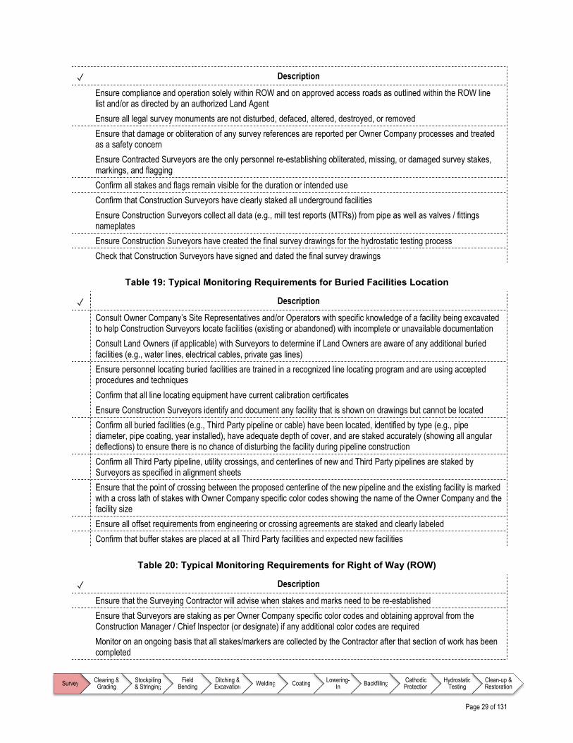
✓ Description
Ensure compliance and operation solely within ROW and on approved access roads as outlined within the ROW line list and/or as directed by an authorized Land Agent
Ensure all legal survey monuments are not disturbed, defaced, altered, destroyed, or removed Ensure that damage or obliteration of any survey references are reported per Owner Company processes and treated
as a safety concern Ensure Contracted Surveyors are the only personnel re-establishing obliterated, missing, or damaged survey stakes,
markings, and flagging
Confirm all stakes and flags remain visible for the duration or intended use
Confirm that Construction Surveyors have clearly staked all underground facilities
Ensure Construction Surveyors collect all data (e.g., mill test reports (MTRs)) from pipe as well as valves / fittings nameplates
Ensure Construction Surveyors have created the final survey drawings for the hydrostatic testing process
Check that Construction Surveyors have signed and dated the final survey drawings
Table 19: Typical Monitoring Requirements for Buried Facilities Location
✓ Description
Consult Owner Company’s Site Representatives and/or Operators with specific knowledge of a facility being excavated to help Construction Surveyors locate facilities (existing or abandoned) with incomplete or unavailable documentation
Consult Land Owners (if applicable) with Surveyors to determine if Land Owners are aware of any additional buried facilities (e.g., water lines, electrical cables, private gas lines)
Ensure personnel locating buried facilities are trained in a recognized line locating program and are using accepted procedures and techniques
Confirm that all line locating equipment have current calibration certificates
Ensure Construction Surveyors identify and document any facility that is shown on drawings but cannot be located
Confirm all buried facilities (e.g., Third Party pipeline or cable) have been located, identified by type (e.g., pipe diameter, pipe coating, year installed), have adequate depth of cover, and are staked accurately (showing all angular deflections) to ensure there is no chance of disturbing the facility during pipeline construction
Confirm all Third Party pipeline, utility crossings, and centerlines of new and Third Party pipelines are staked by Surveyors as specified in alignment sheets
Ensure that the point of crossing between the proposed centerline of the new pipeline and the existing facility is marked with a cross lath of stakes with Owner Company specific color codes showing the name of the Owner Company and the facility size
Ensure all offset requirements from engineering or crossing agreements are staked and clearly labeled
Confirm that buffer stakes are placed at all Third Party facilities and expected new facilities
Table 20: Typical Monitoring Requirements for Right of Way (ROW)
✓ Description
Ensure that the Surveying Contractor will advise when stakes and marks need to be re-established
Ensure that Surveyors are staking as per Owner Company specific color codes and obtaining approval from the Construction Manager / Chief Inspector (or designate) if any additional color codes are required
Monitor on an ongoing basis that all stakes/markers are collected by the Contractor after that section of work has been completed

Page 30 of 131
Survey Clearing & Grading
Stockpiling & Stringing
Field Bending
Ditching & Excavation Welding Coating Lowering-
In Backfilling Cathodic Protection
Hydrostatic Testing
Clean-up & Restoration
✓ Description
Ensure that Surveyors are staking the pipeline route, valves, and other appurtenances as shown on the drawings
Ensure that Surveyors have correctly labeled all the stakes and these are visible from the work side or within the work area of the ROW
Confirm that the boundaries of the ROW or temporary work space (TWS) are staked as per survey specifications
Ensure that Surveyors are using frost pins or similar tools in hard or frozen ground when securing survey markers
Ensure that taller stakes are installed in high crop areas or snow to ensure visibility, and hub staking (a means of staking that is resistant to being knocked down) is used in livestock pastures
Ensure watercourse crossings have the appropriate riparian zone (interface between land and a river or stream) buffers starting from the top of the bank, unless otherwise shown on drawings
Ensure that progress stakes are placed along the edge of the ROW or TWS at specified intervals so they are visible on the work side or within the work area
Ensure that flagging is placed more frequently in heavier vegetated and treed areas to provide better visibility for Clearing Equipment Operators
Table 21: Typical Monitoring Requirements for Ditch Line
✓ Description
Ensure the centerline of the proposed pipeline ditch is staked at specified intervals, except at bends and crossings where the intervals will be more frequent
Ensure Surveyors are breaking down large angle bends at points of intersection (PI) into a series of smaller bends when the PI angle exceeds bending specifications (done to ensure that the bends fit the right of way)
Ensure angles (degrees, minutes, and seconds) of deflection are recorded at all pipeline deflection points
Ensure Surveyors are using chainages / station numbers (an imaginary line used to measure distance that corresponds to the centerline of for example a pipeline or a fence), for example: In Canada, use metric chainages with 3 digits and 1 decimal point (e.g., 2+145.1 = 2145.1 m) In U.S., use imperial station numbers (e.g., 10,000 ft would be 100+00)
Document and inform the Construction Manager / Chief Inspector (or designate) of any major deviations or necessary changes in chainage / station equations
Table 22: Typical Monitoring Requirements for Crossings
✓ Description
Ensure activities are coordinated with the Owner Company as well as Third Party Facility Owners through One Call / 811 Call
Ensure Surveyors are measuring contour changes along the ditch line, accounting for the terrain (including crossings) to be bored or horizontally directionally drilled (HDD)
Ensure all features and offsets of design crossings are staked according to the construction drawings Confirm the staking of entry and exit points of any drill or bore, to ensure the locations and respective workspaces are
marked and consistent with drawings Ensure temporary bench marks are placed on the work side of the right of way (ROW) in a location of minimal
disturbance, showing an elevation referenced to the crossing drawings (temporary bench marks could be set on each side of the ROW in case of disturbance)
Confirm that for typical crossings, all cadastral boundaries (i.e., legal land ownership limits) crossed are staked to show the relative disposition and are labeled with name of the Owner Company as well as pipeline type and size
Ensure all offset requirements from engineering or crossing agreements are staked and clearly labeled

Page 31 of 131
Survey Clearing & Grading
Stockpiling & Stringing
Field Bending
Ditching & Excavation Welding Coating Lowering-
In Backfilling Cathodic Protection
Hydrostatic Testing
Clean-up & Restoration
✓ Description
Confirm that Construction Surveyors for all crossing locations have completed Field Stakeout Reports containing: Field sketches showing all buried facilities in relation to new and existing ROW boundaries List of line locating equipment used Names of Surveyors, date, local area conditions, and all correspondence All visual inspection notes All drawings referenced Signature of Construction Survey Contractor and date on all reports
Table 23: Typical Monitoring Requirements for Appurtenances
✓ Description
Ensure all appurtenances are staked showing the stop, start, and end locations
Report any change in location, spacing, and quantity to the Construction Manager / Chief Inspector (or designate)
Table 24: Typical Monitoring Requirements for As-Builts
✓ Description
Meet with the Surveyors daily to identify areas requiring as-built data
Ensure Construction Surveyors are collecting as-built data continually during construction and are not impeding the progress of the Contractor
Ensure that once belowground as-built data has been collected, the Construction Surveyors have staked the location
Note the start and end chainages / stations of as-built data collection
Table 25: Typical Monitoring Requirements for Pilings
✓ Description
Ensure the Construction Surveyors, in conjunction with the Contractor, have identified all pilings
Ensure the Construction Surveyors, in conjunction with the Contractor, have marked all piles using iron spikes and wooden laths labeled with the pile numbers
Ensure the Construction Surveyors, in conjunction with the Contractor, are collecting elevation data at the pile cut-off, grade, and bottom of day-lighted (the act of uncovering and exposing buried utilities) holes referenced to the site data as shown on the Construction Plan
Table 26: Typical Monitoring Requirements for Caliper Pigging
✓ Description
Ensure Construction Surveyors have produced a complete data set containing all weld and bend information before any caliper runs
Ask the Construction Surveyors to locate and stake any indications along the pipeline based on the caliper run results

Page 32 of 131
Survey Clearing & Grading
Stockpiling & Stringing
Field Bending
Ditching & Excavation Welding Coating Lowering-
In Backfilling Cathodic Protection
Hydrostatic Testing
Clean-up & Restoration
7.7 Typical Outputs for Survey Inspection
Table 27: Typical Reporting Requirements
✓ Description
General
Ensure redline drawings are complete, checked, and forwarded to the Construction Manager / Chief Inspector (or designate), and Others (as directed) in accordance with Survey Plan
Daily
Complete survey progress reports, including: Work completed to date, including:
o Start and end chainage / station number o A complete set of redlined drawings identifying the as-built records for the pipeline (detailed
requirements should be included in the Survey Contractor’s scope) o Survey support sketches and data to explain as-built records (where required) o Survey support documentation to field RFIs (Requests for Information)
References – Survey
Note to user: The reference information provided in Table 28 is intended as a guide only (i.e., the list is not exhaustive); documents of this nature are updated frequently and it remains the responsibility of the user to ensure that the correct, and most current, documents are referenced as appropriate.
Table 28: List of References – Survey
Document No. Type Title
American Petroleum Institute (API)
API RP 1102 Recommended Practice Steel Pipeline Crossing Railroad and Highways
Common Ground Alliance (CGA)
N/A Recommended Practice Best Practices
INGAA Foundation
N/A Guideline Guidance Documents for Construction – Natural Gas Pipeline Crossing Guidelines
CS-S-8 Guideline Construction Safety Consensus Guidelines – Overhead Utilities Safety

Page 33 of 131
Survey Clearing & Grading
Stockpiling & Stringing
Field Bending
Ditching & Excavation Welding Coating Lowering-
In Backfilling Cathodic Protection
Hydrostatic Testing
Clean-up & Restoration
8.0 CLEARING AND GRADING
8.1 Overview
Clearing and grading is the next phase of pipeline construction after surveying, where the pipeline right of way (ROW) is prepared for the upcoming pipeline installation activities. Key steps of the clearing and grading process typically include:
Cutting, removal, or burning of trees, brush, and debris from the pipeline ROW
Timber salvage; the recovery and temporary storage of useful, merchantable timber from the ROW
Unsalvageable timber disposal; the removal or elimination on-site of non-merchantable timber and brush by chipping, mulching, or burning
Grubbing; the removal of tree stumps and large roots from specific areas of the ROW
Use of non-merchantable timber (often called rip-rap, corduroy, and rollback) to build roads or pathways for vehicles and equipment or to create barriers for erosion control
Preparation and maintenance of ROW access
Frost packing (for winter activities)
Line location of buried utilities
Fencing (for agricultural lands)
Stripping and storage of topsoil for later redistribution after the pipe has been backfilled
In some cases, grade rock blasting, excavation, and removal may be required
8.2 Inputs
As part of preparing for inspection during the clearing and grading process, the Inspector will continually familiarize themselves with relevant aspects of key documents, drawings, and Owner Company technical specifications as identified in Table 30.
8.3 Execution
While the work is being executed, the Inspector is required to monitor workmanship and report on progress on a periodic basis. Typical items that the Inspector will monitor for during the clearing and grading process are identified in a series of checklists as detailed in Table 29.

Page 34 of 131
Survey Clearing & Grading
Stockpiling & Stringing
Field Bending
Ditching & Excavation Welding Coating Lowering-
In Backfilling Cathodic Protection
Hydrostatic Testing
Clean-up & Restoration
Table 29: Monitoring Requirements for Clearing and Grading
Item Description Reference
Prior to Commencing Work
On a daily basis, ensure key issues that have been identified are detailed and addressed
Table 31
Safety Monitor the operations for adherence to relevant Owner Company and project specific safety requirements
Table 32
Environmental Considerations
Identifies specific items that should be monitored throughout Clearing and Grading Operations that relate specifically to the Owner Company and/or project specific Environmental Protection Plan (EPP)
Table 33
Clearing Monitor the operations for adherence to relevant Owner Company and project specific requirements for Clearing (i.e., cutting of brush and trees)
Table 34
Temporary Work Spaces (TWS)
Temporary work spaces, also known as push outs, allow for maneuvering of equipment as turn-arounds or possibly temporary decking (i.e., storage) areas for salvaged timber
Table 35
Access Road Preparation
Existing roads are used to transport equipment and supplies to the ROW. Where no roads exist, temporary access roads are constructed and are removed after construction has been completed
It is imperative that all access roads are capable of withstanding the loads being transported and the frequency of intended use. When access roads need to be constructed and have been approved, the Inspector will ensure they are constructed as detailed by Owner Company and project specific requirements
Table 36
Gates and Fences Existing structures (e.g., fencing) should be altered to accommodate construction operations, and where possible, returned to its original state after construction is completed
New fencing and structures are immediately erected to contain livestock, and where possible, returned to its original state after construction is completed
Gates will be installed to allow, in most cases, permanent access to pipeline facilities
Table 37
Buried Facilities In most cases, existing buried facilities on a ROW (e.g., an existing pipeline) will require temporary aboveground mechanical support o Typically, earthen ramps or mats are installed before construction
equipment can cross the surface to prevent undue stress / potential damage to underground facilities
Table 38
Timber Incorporates items for removal, salvage, and disposal of timber and brush including considerations specific to watercourses
Land Owner’s crop removal requirements (e.g., Contractor may cut and remove crops from the ROW and store per conditions established between the Owner Company and the Land Owner’s requirements)
Discuss Crossing Plan with Environmental Inspector to identify specific requirements when clearing occurs at or near a watercourse
Table 39
Grubbing Grubbing ensures subsoil is free of stumps, roots, and debris to eliminate the possibility of damaging the pipe when the soil is placed back into the pipeline trench during backfilling
Table 40
Snow Berms Address specific considerations related to creating snow piles, primarily to prevent freezing of the pipeline trench
Table 41

Page 35 of 131
Survey Clearing & Grading
Stockpiling & Stringing
Field Bending
Ditching & Excavation Welding Coating Lowering-
In Backfilling Cathodic Protection
Hydrostatic Testing
Clean-up & Restoration
Item Description Reference
Grade Rock Blasting and Removal
Grade rock blasting with explosives by a Third Party Contractor may be required in cases where the rock is too hard to break by ripping; blasting operations require extra caution and awareness due to associated safety risks
All requirements as listed in the approved Blasting Plan should be monitored for
Table 42
Swamps and Muskegs Specific considerations relating to land that is particularly sensitive to construction activity
Table 43
Topsoil Stripping Topsoil stripping is where the topsoil is segregated to the depth and width as defined by Owner Company specifications, then the segregated amount is salvaged and stockpiled on the side of the ROW, to be spread back over the area after final grading is complete
Table 44
Grading Grading refers to leveling the pipeline ROW so that construction can proceed smoothly and safely along the ROW
Grading includes topsoil stripping and piling as well as the installation of flumes (ditches that run next to existing pipe trench) and bridges
Table 45
8.4 Outputs
The Inspector is required to report on workmanship and progress on a periodic basis (e.g., daily or weekly) by completing various reports on each work day and end of week. Report requirements and reporting processes are Owner Company and project specific; however, best practices for reporting requirements for clearing and grading appear in Table 46.
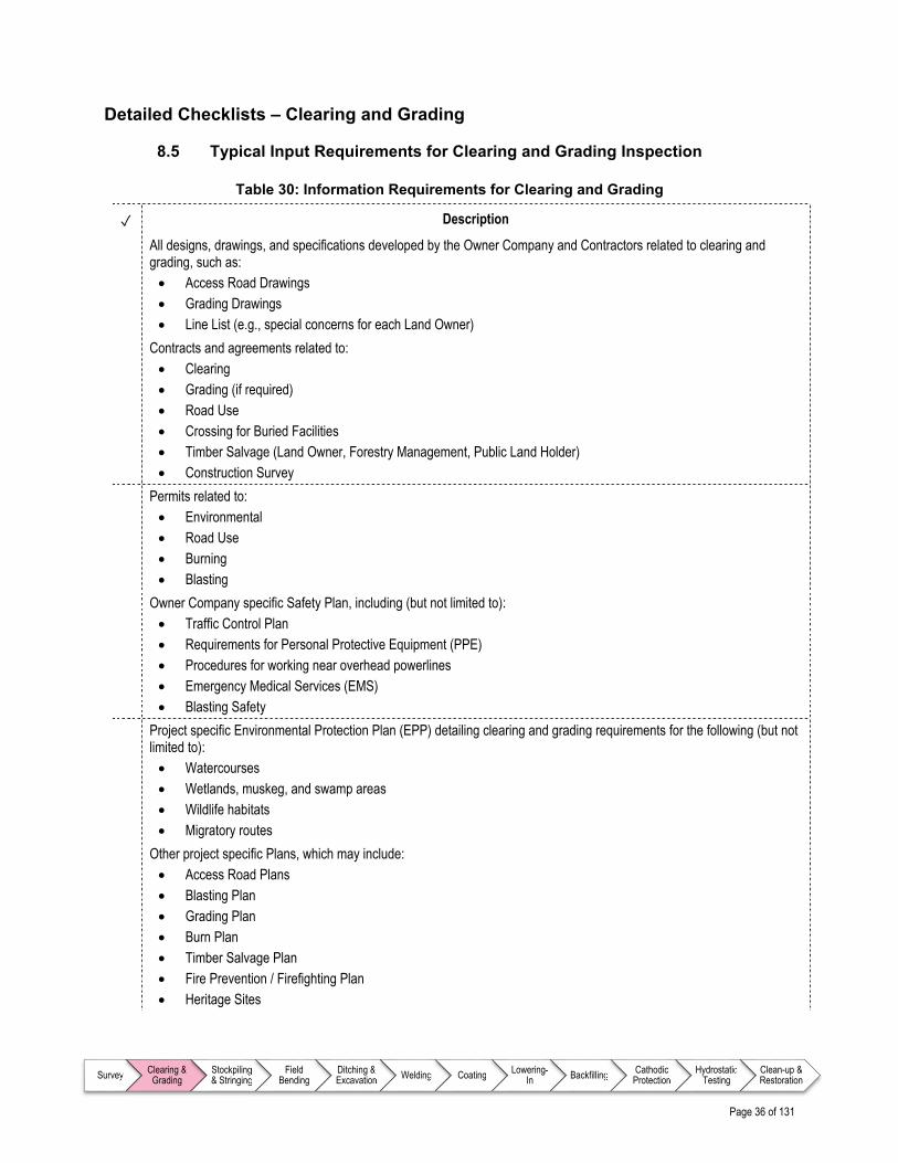
Page 36 of 131
Survey Clearing & Grading
Stockpiling & Stringing
Field Bending
Ditching & Excavation Welding Coating Lowering-
In Backfilling Cathodic Protection
Hydrostatic Testing
Clean-up & Restoration
Detailed Checklists – Clearing and Grading
8.5 Typical Input Requirements for Clearing and Grading Inspection
Table 30: Information Requirements for Clearing and Grading
✓ Description
All designs, drawings, and specifications developed by the Owner Company and Contractors related to clearing and grading, such as: Access Road Drawings Grading Drawings Line List (e.g., special concerns for each Land Owner)
Contracts and agreements related to: Clearing Grading (if required) Road Use Crossing for Buried Facilities Timber Salvage (Land Owner, Forestry Management, Public Land Holder) Construction Survey
Permits related to: Environmental Road Use Burning Blasting
Owner Company specific Safety Plan, including (but not limited to): Traffic Control Plan Requirements for Personal Protective Equipment (PPE) Procedures for working near overhead powerlines Emergency Medical Services (EMS) Blasting Safety
Project specific Environmental Protection Plan (EPP) detailing clearing and grading requirements for the following (but not limited to): Watercourses Wetlands, muskeg, and swamp areas Wildlife habitats Migratory routes
Other project specific Plans, which may include: Access Road Plans Blasting Plan Grading Plan Burn Plan Timber Salvage Plan Fire Prevention / Firefighting Plan Heritage Sites

Page 37 of 131
Survey Clearing & Grading
Stockpiling & Stringing
Field Bending
Ditching & Excavation Welding Coating Lowering-
In Backfilling Cathodic Protection
Hydrostatic Testing
Clean-up & Restoration
8.6 Best Practice Items for Inspecting Typical Clearing and Grading Operations
Table 31: Prior to Commencing Work
✓ Description
Participate in daily meetings to address: Job safety and/or hazard identification issues Environmental concerns Duties of Inspector(s) Pipeline Contractor’s tailgate meetings (as required) Ad-hoc meetings with Contractors to discuss and clarify questions or concerns
Ensure Pre-Blast Survey is conducted and documented
Ensure well water monitoring system is installed and functional
Table 32: Safety Concerns for Clearing and Grading
✓ Description
Ensure that risks associated with blasting operations (e.g., fly-rock, vibration, use of explosives, undetonated explosives) are identified and sufficient safety precautions are put in place
Table 33: Typical Monitoring Requirements for Environmental Considerations
✓ Description
Ensure topsoil stripping is conducted in accordance with the environmental specifications
Table 34: Typical Monitoring Requirements for Clearing
✓ Description
Monitor for adherence to conditions noted in all approvals and permits issued Clearing is limited to vegetation within the approved ROW and approved work areas Monitor for proper placement of all removed trees and brush from and adjacent to the ROW Identify any areas where additional clearing (previously out of scope work) may be required Ensure the Contractor will strip, salvage, and store the topsoil before grading the ROW and store it along the ROW Ensure topsoil and subsoil is kept in separate stockpiles Identify potential for delays to planned work

Page 38 of 131
Survey Clearing & Grading
Stockpiling & Stringing
Field Bending
Ditching & Excavation Welding Coating Lowering-
In Backfilling Cathodic Protection
Hydrostatic Testing
Clean-up & Restoration
Table 35: Typical Monitoring Requirements for Temporary Work Spaces
✓ Description
Ensure Construction Manager / Chief Inspector (or designate) approvals for push outs are in place prior to construction
Ensure push outs along the outer edge of the pipeline ROW are constructed in approved areas only
Ensure any temporary work space (TWS) (area usually adjacent to the permanent Right-Of-Way to be used for construction purposes) for storage of excavated material, grubbing, or salvageable timber has been approved by the Construction Manager / Chief Inspector (or designate), if required
Table 36: Typical Monitoring Requirements for Access Road Preparation
✓ Description
Monitor for adherence to all requirements identified in project road use agreement(s)
Ensure Contractor uses only subsoil (no topsoil) for building road approaches
Ensure Clearing and Grading Contractors operate on only designated or permitted access roads and work areas
Monitor Contractors for compliance with load limits on roads and bridges established by road use agreement(s) and respective authorities
Ensure use of mats or clear span bridges for water crossings where culverts and fill material cannot be constructed
During winter, ensure frost is driven into the ground (frost packing) on the work side of the ROW
During winter, ensure use of mats or clear span bridges for water crossings where snow fills and ice bridges cannot be constructed
Table 37: Typical Monitoring Requirements for Gates and Fences
✓ Description
Ensure Contractor builds and/or replaces fences and installs gates that cross the pipeline route per Land Owner agreement(s) and Owner Company specifications
Check that fences are properly braced and that gates will close and can be properly secured
Ensure a watchperson is present at open gates to control livestock (if required)
Table 38: Typical Monitoring Requirements for Buried Facilities
✓ Description
Ensure only subsoil (no topsoil) is used to construct earthen ramps Ensure earthen ramps are constructed to the minimum height and width above natural ground surface at the point of
crossing specified by crossing agreement(s) Ensure line list is reviewed on an ongoing basis to address all Land Owner and Third Party Utility Owner concerns Confirm all construction activities cease the specified distance away from any unprepared crossings
Table 39: Typical Monitoring Requirements for Timber Processing
✓ Description
Timber Removal
Ensure that only approved equipment is used (e.g., cut-off type saw equipment to cut trees by hand)
Ensure that specimen trees and shrubs identified in the Environmental Protection Plan (EPP) are marked and protected both along and marginally off the ROW or work spaces by an approved method (e.g., rubber tires or safety fences)

Page 39 of 131
Survey Clearing & Grading
Stockpiling & Stringing
Field Bending
Ditching & Excavation Welding Coating Lowering-
In Backfilling Cathodic Protection
Hydrostatic Testing
Clean-up & Restoration
✓ Description
Record exact species and locations of specimen trees and shrubs to assist in re-planting / replacement during clean-up and restoration phase
Ensure Clearing Contractor has obtained approvals from the Construction Manager / Chief Inspector (or designate) before pushing any timber outside the ROW and/or cutting any trees off the ROW
Ensure Contractor fells trees to minimize butt shatter and breakage towards and within the ROW
Confirm the Contractor brings the cut trees back within the ROW for processing for trees felled outside the ROW
Ensure cuts are treated per contract requirements where branches are removed from a standing tree outside the ROW (if required)
Confirm the Contractor cuts, de-limbs, skids, and stockpiles merchantable timber to designated areas
Monitor for adherence to specific requirements for salvage, storage, and removal associated that may be specific to the type of Land Owner (e.g., Freehold, Aboriginal, Crown, National/State)
Confirm need for, and monitor operations of timber scaler (to calculate the volume and weight of the timber stockpiles to facilitate contractual payments)
Confirm segregation of merchantable timber according to project specifications
Ensure Contractor refrains from skidding timber through partially thawed and/or muddy ground, watercourses, water bodies, or wetlands
Ensure that on land with a significant slope (per criteria defined by Owner Company in contract documents) in any direction, removal of brush and trees is minimized and root systems are left intact to prevent slope erosion
Monitor for adherence to special conditions for disposal of trees on hillsides
Ensure the ROW is cleared of all trees, brush, and debris to prevent mixing with excavated soils that will be returned to ditch during backfill
Ensure salvaged topsoil is cleared of roots and debris
Timber Removal – Watercourses
Ensure timely notice is given to all agreed-to parties before starting work near a creek, river, or watercourse
Ensure adherence to any specific requirements associated with timber removal near watercourses
Ensure Contractor plans and prepares in advance for moving equipment across watercourses
Ensure that existing water crossings are used, where possible
Ensure trees, shrubs, and riparian vegetation is preserved as much as practicable near all watercourses to address operational and safety concerns
Ensure proper approvals are in place prior to installing temporary crossings across ditches and drainages
Ensure that only approved types of temporary crossings are installed over watercourses if no bridge exists. Approved temporary crossing types may include: Clear span bridge Ice bridge Snow bridges (built with clean snow) Flumes Rock fill
Ensure that topsoil is never used to fill stream crossings
Ensure all trees are felled away from watercourses
Ensure any felled trees are removed from watercourses immediately
Ensure that no debris falls/deposits into watercourses
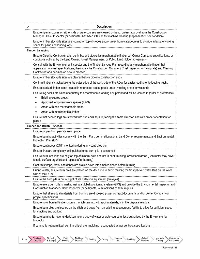
Page 40 of 131
Survey Clearing & Grading
Stockpiling & Stringing
Field Bending
Ditching & Excavation Welding Coating Lowering-
In Backfilling Cathodic Protection
Hydrostatic Testing
Clean-up & Restoration
✓ Description
Ensure riparian zones on either side of watercourses are cleared by hand, unless approval from the Construction Manager / Chief Inspector (or designate) has been attained for machine clearing (dependent on soil condition)
Ensure timber stockpile sites are located on top of slopes and/or away from watercourses to provide adequate working space for piling and loading logs
Timber Salvaging
Ensure Clearing Contractor cuts, de-limbs, and stockpiles merchantable timber per Owner Company specifications, or conditions outlined by the Land Owner, Forest Management, or Public Land Holder agreements
Consult with the Environmental Inspector and the Timber Salvage Plan regarding any merchantable timber that appears to not meet specifications, then notify the Construction Manager / Chief Inspector (or designate) and Clearing Contractor for a decision on how to proceed
Ensure timber stockpile sites are cleared before pipeline construction ends
Confirm timber is stacked along the outer edge of the work side of the ROW for easier loading onto logging trucks
Ensure stacked timber is not located in reforested areas, grade areas, muskeg areas, or wetlands
Ensure log decks are sized adequately to accommodate loading equipment and will be located in (order of preference): Existing cleared areas Approved temporary work spaces (TWS) Areas with non-merchantable timber
Areas with merchantable timber
Ensure that decked logs are stacked with butt ends square, facing the same direction and with proper orientation for pickup
Timber and Brush Disposal
Ensure proper burn permits are in place
Ensure burning activities comply with the Burn Plan, permit stipulations, Land Owner requirements, and Environmental Protection Plan (EPP)
Ensure continuous (24/7) monitoring during any controlled burn
Ensure fires are completely extinguished once burn pile is consumed
Ensure burn locations are only on top of mineral soils and not in peat, muskeg, or wetland areas (Contractor may have to strip surface organics and replace after burning)
Confirm stumps, roots, and debris are broken down into smaller pieces before burning
During winter, ensure burn piles are placed on the ditch line to avoid thawing the frost-packed traffic lane on the work side of the ROW
Ensure the burn pile is out of sight of fire detection equipment (fire eyes)
Ensure every burn pile is marked using a global positioning system (GPS) and provide the Environmental Inspector and Construction Manager / Chief Inspector (or designate) with locations of all burn piles
Ensure that all residual materials from burning are disposed as per contract documents and/or Owner Company or project specifications
Ensure no unburned timber or brush, which can mix with spoil materials, is in the disposal residue
Ensure burn piles are located on the ditch and away from an existing aboveground facility to allow for sufficient space for stacking and working
Ensure burning is never undertaken near a body of water or watercourse unless authorized by the Environmental Inspector
If burning is not permitted, confirm chipping or mulching is conducted as per contract specifications

Page 41 of 131
Survey Clearing & Grading
Stockpiling & Stringing
Field Bending
Ditching & Excavation Welding Coating Lowering-
In Backfilling Cathodic Protection
Hydrostatic Testing
Clean-up & Restoration
✓ Description
Ensure Clearing Contractor hauls away all timber and brush from the ROW that cannot be processed by the above means
Table 40: Typical Monitoring Requirements for Grubbing
✓ Description
Ensure stumps are grubbed and other debris is cleared from the ditch line but stored within the ROW
Ensure leftover tree stumps are chipped to a specified height in locations where grubbing is not necessary
On the work side of the ROW, ensure Contractor leaves as many stumps as possible to maintain soil cohesion, compaction, and to provide a stable surface for construction equipment and vehicles
On Crown / Public land, ensure Contractor removes all stumps from the spoil side of the ROW including the ditch line
On Freehold (including unimproved Freehold) and Aboriginal land which could be agriculturally productive, ensure Contractor grubs and disposes of all stumps, roots, and surface rocks from the entire ROW
Table 41: Typical Monitoring Requirements for Snow Berms
✓ Description
Ensure snow berms are built to Owner Company specifications over the ditch line immediately after clearing to prevent frost penetration into the pipeline trench
Ensure that gaps are left in snow berms at specified intervals to allow for passage of livestock and wildlife
Table 42: Typical Monitoring Requirements for Grade Rock Blasting and Removal
✓ Description
Confirm pre-blast survey has been completed
Confirm an approved Blasting Plan is in place
Ensure that the Contractor has obtained permits for the use and storage of explosives
Check that only qualified drilling and blasting personnel are employed in the blasting operations
Ensure the Contractor has seismic monitoring equipment for blasting in place to monitor Peak Particle Velocity (PPV) limits
Ensure blasting notifications are in place and are being clearly communicated
Monitor for loose rock scattering onto the ROW, adjacent land, or causing damage to equipment / property
Verify that the Contractor picks up and properly disposes of any fly-rock from blasting activities
Table 43: Typical Monitoring Requirements for Swamps and Muskegs
✓ Description
Ensure the Clearing Contractor clears wetland and muskeg areas using approved Owner Company procedures and per the Environmental Protection Plan (EPP)
Ensure trees are cut flush to the terrain surface
Ensure stumps are cut flush to the terrain surface and are not grubbed to avoid unnecessary vegetation disturbance
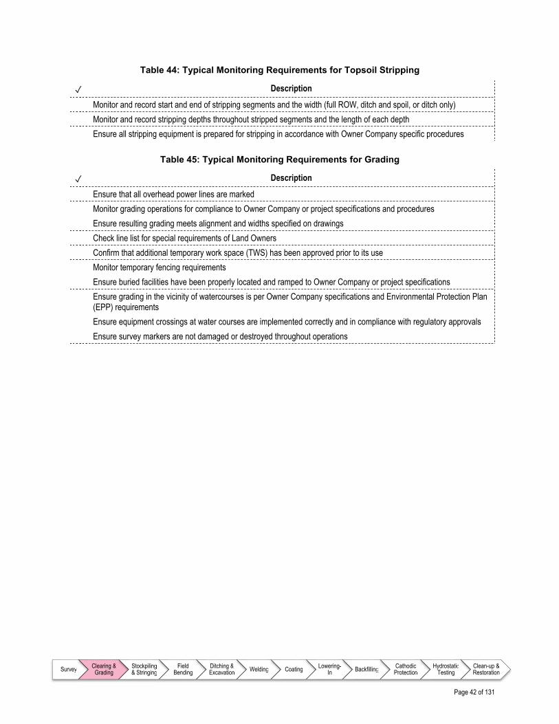
Page 42 of 131
Survey Clearing & Grading
Stockpiling & Stringing
Field Bending
Ditching & Excavation Welding Coating Lowering-
In Backfilling Cathodic Protection
Hydrostatic Testing
Clean-up & Restoration
Table 44: Typical Monitoring Requirements for Topsoil Stripping
✓ Description
Monitor and record start and end of stripping segments and the width (full ROW, ditch and spoil, or ditch only)
Monitor and record stripping depths throughout stripped segments and the length of each depth
Ensure all stripping equipment is prepared for stripping in accordance with Owner Company specific procedures
Table 45: Typical Monitoring Requirements for Grading
✓ Description
Ensure that all overhead power lines are marked
Monitor grading operations for compliance to Owner Company or project specifications and procedures
Ensure resulting grading meets alignment and widths specified on drawings
Check line list for special requirements of Land Owners
Confirm that additional temporary work space (TWS) has been approved prior to its use
Monitor temporary fencing requirements
Ensure buried facilities have been properly located and ramped to Owner Company or project specifications
Ensure grading in the vicinity of watercourses is per Owner Company specifications and Environmental Protection Plan (EPP) requirements
Ensure equipment crossings at water courses are implemented correctly and in compliance with regulatory approvals
Ensure survey markers are not damaged or destroyed throughout operations
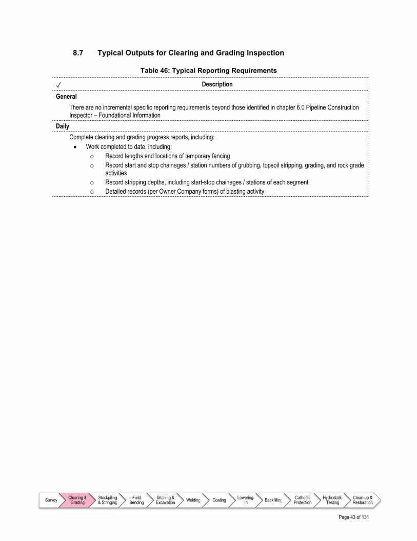
Page 43 of 131
Survey Clearing & Grading
Stockpiling & Stringing
Field Bending
Ditching & Excavation Welding Coating Lowering-
In Backfilling Cathodic Protection
Hydrostatic Testing
Clean-up & Restoration
8.7 Typical Outputs for Clearing and Grading Inspection
Table 46: Typical Reporting Requirements
✓ Description
General
There are no incremental specific reporting requirements beyond those identified in chapter 6.0 Pipeline Construction Inspector – Foundational Information
Daily
Complete clearing and grading progress reports, including: Work completed to date, including:
o Record lengths and locations of temporary fencing o Record start and stop chainages / station numbers of grubbing, topsoil stripping, grading, and rock grade
activities o Record stripping depths, including start-stop chainages / stations of each segment o Detailed records (per Owner Company forms) of blasting activity

Page 44 of 131
Survey Clearing & Grading
Stockpiling & Stringing
Field Bending
Ditching & Excavation Welding Coating Lowering-
In Backfilling Cathodic Protection
Hydrostatic Testing
Clean-up & Restoration
References – Clearing and Grading
Note to user: The reference information provided in Table 47 is intended as a guide only (i.e., the list is not exhaustive); documents of this nature are updated frequently and it remains the responsibility of the user to ensure that the correct, and most current, documents are referenced as appropriate.
Table 47: List of References – Clearing and Grading
Document No. Type Title
American Petroleum Institute (API)
API RP 1172 Recommended Practice Recommended Practice for Construction Parallel to Existing Underground Transmission Pipelines
Canadian Energy Pipeline Association (CEPA)
N/A Report Pipeline Associated Watercourse Crossings

Page 45 of 131
Survey Clearing & Grading
Stockpiling & Stringing
Field Bending
Ditching & Excavation Welding Coating Lowering-
In Backfilling Cathodic Protection
Hydrostatic Testing
Clean-up & Restoration
9.0 STOCKPILING AND STRINGING
9.1 Overview
For projects of significant size, Owner Company-provided materials are received at a marshalling yard or stockpiling site, typically located away from the right of way (ROW), for temporary storage. The Inspector is typically responsible for:
Inspection of all received materials and log into Material Receiving Reports (MRRs) as required by Owner Company
Quarantine and return of any materials that are damaged or do not meet specifications according to the Owner Company’s processes
At the point of receipt of materials on site, both the Inspector and a Contractor Representative will inspect, verify, and receive every shipment. The Contractor immediately takes possession and responsibility for the received materials. Depending on project size and scope, the Inspector may also be assigned to assist a designated Materials Coordinator. More specifically, the inspector will understand and comply with the Owner Company’s Inspection and Materials Traceability Standards as well as Quality Control processes and forms. Stringing involves placing pipe joints end to end along the pipeline ROW, including:
Strategically placing pipe section supports (e.g., wooden skids or plastic tubs) next to the proposed pipeline ditch (in some cases trench may already be dug)
Transporting the coated pipe from stockpile sites and placing the pipe on top of the skids; this includes laying out material for specific crossings (e.g., water, road, railroad, HDD), sidebends, etc.
9.2 Inputs
As part of preparing for inspection during the stockpiling and stringing process, the Inspector will be familiar with relevant aspects of key Owner Company documents, drawings, and materials technical specifications as identified in Table 49.
9.3 Execution
While the work is being executed, Inspectors are required to monitor workmanship and report on progress on a periodic basis. Typical items that Inspectors will monitor for during the stockpiling and stringing process are identified in Table 48.

Page 46 of 131
Survey Clearing & Grading
Stockpiling & Stringing
Field Bending
Ditching & Excavation Welding Coating Lowering-
In Backfilling Cathodic Protection
Hydrostatic Testing
Clean-up & Restoration
Table 48: Typical Monitoring Requirements for Executing Stockpiling and Stringing Operations
Item Description Reference
Prior to Commencing Work
On a daily basis, ensure key issues that have been identified are detailed and addressed
Table 50
Safety Monitor the operations for adherence to relevant Owner Company and project specific safety requirements
Table 51
Environmental Considerations
Identifies specific items that should be monitored throughout Stockpiling and Stringing operations that relate specifically to the Owner Company and/or project specific Environmental Protection Plan (EPP)
Table 52
Receiving / Custody Transfer
Involves confirmation that appropriate pipe has been shipped and received in good condition and with required documentation (i.e., MTRs) prior to the Contractor taking responsibility
Table 53
Transport and Handling Use of cranes, rigging and lifting, load handling, and signaling procedures to ensure safety and preserve material integrity
Table 54
Storage / Stockpiling Proper storage of pipe (e.g., strategic stacking based on part number) Table 55
Identifying and Addressing Pipe Damage
Inspection and repair of any damage pipe and/or coating Table 56
Stringing Ensure that the correct pipe sections in the proper sequence are transported and placed on the ROW with appropriate supports in place in preparation for welding
Table 57
9.4 Outputs
The Inspector is required to report on workmanship and progress on a periodic basis (e.g., daily or weekly) by completing various reports on each work day and end of week. Report requirements and reporting processes are Owner Company and project specific; however, best practices for reporting requirements for stockpiling and stringing appear in Table 58.

Page 47 of 131
Survey Clearing & Grading
Stockpiling & Stringing
Field Bending
Ditching & Excavation Welding Coating Lowering-
In Backfilling Cathodic Protection
Hydrostatic Testing
Clean-up & Restoration
Detailed Checklists – Stockpiling and Stringing
9.5 Typical Inputs for Stringing and Stockpiling Inspection
Table 49: Information Requirements for Stringing and Stockpiling
✓ Description
All designs, drawings, and technical specifications developed by the Owner Company and Contractors related to stockpiling and stringing, such as: Bill of Materials (BOM) Alignment Sheets Pipe Tallies Pipe Stocking Specifications Pipe Stringing Specifications Specifications detailing acceptable size and nature of pipe and coating defects Specifications detailing acceptable repair methods and practices for pipe and coating defects Owner Company specific Materials Transfer Form
Contracts and agreements related to: Transport and Handling of Materials Inspection of Materials Materials Storage
Permits related to: Road Transport
Owner Company specific Safety Plan, including (but not limited to): Pipe Transport Pipe Loading / Unloading Pipe Storage Handling of Materials
Project specific Environmental Protection Plan (EPP), detailing stockpiling and stringing requirements
Other project specific Plans, which may include: Traffic Control Plan

Page 48 of 131
Survey Clearing & Grading
Stockpiling & Stringing
Field Bending
Ditching & Excavation Welding Coating Lowering-
In Backfilling Cathodic Protection
Hydrostatic Testing
Clean-up & Restoration
9.6 Best Practices for Typical Stringing and Stockpiling Inspection
Table 50: Prior to Commencing Work
✓ Description
Participate in daily meetings to address: Job safety and/or hazard identification issues Environmental concerns Duties of Inspector(s) Pipeline Contractor’s tailgate meetings (as required) Ad-hoc meetings with Contractors to discuss and clarify questions or concerns Confirm next day’s stringing requirements for line pipe and heavy wall
Equipment: Confirm all Equipment Operators have appropriate certification / ticket(s) Confirm Contractor possesses Manufacturer information / manual of the machinery operated Ensure that all lifting equipment is inspected (e.g., slings and cables) for damage and all findings documented
before use
Ensure changes in wall thickness and bend locations are staked prior to stringing and correct pipe sections are placed incrementally along the right of way (ROW)
Table 51: Safety Concerns for Stringing and Stockpiling
✓ Description
Use caution while inspecting pipe unloading as each joint is extremely heavy
Monitor for individuals standing between a suspended load and equipment or pipe
Ensure all pipes are properly chocked
Ensure individuals stand clear when metal banding is cut loose or other tie down means are loosened from the load
Stand clear of lifting slings or vacuum lifters while the Equipment Operator is lifting and placing pipe joints
Ensure eye contact is made with the Equipment Operator to establish an understanding of intentions when inspecting pipe and wait for Operator’s signal before proceeding
Monitor and be aware of other vehicles moving in the stockpile yard or right of way (ROW)
Understand equipment limitations related to weather, such as vac-lifts and frost
Table 52: Typical Monitoring Requirements for Environmental Considerations
✓ Description
There are no incremental specific Environmental Considerations beyond those identified in chapter 6.0 Pipeline Construction Inspector – Foundational Information
Table 53: Monitoring Requirements for Receiving / Custody Transfer
✓ Description
Check that the pipe received at the stockpile location against the pipe tally sheet (number and length of each pipe joint the pipe mill has sent)
Check that all the pipe joints have end caps
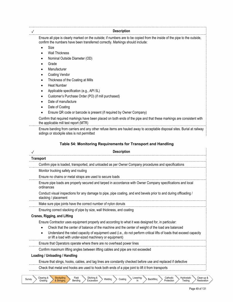
Page 49 of 131
Survey Clearing & Grading
Stockpiling & Stringing
Field Bending
Ditching & Excavation Welding Coating Lowering-
In Backfilling Cathodic Protection
Hydrostatic Testing
Clean-up & Restoration
✓ Description
Ensure all pipe is clearly marked on the outside; if numbers are to be copied from the inside of the pipe to the outside, confirm the numbers have been transferred correctly. Markings should include: Size Wall Thickness Nominal Outside Diameter (OD) Grade Manufacturer Coating Vendor Thickness of the Coating at Mills Heat Number Applicable specification (e.g., API 5L) Customer’s Purchase Order (PO) (if mill purchased) Date of manufacture Date of Coating Ensure QR code or barcode is present (if required by Owner Company)
Confirm that required markings have been placed on both ends of the pipe and that these markings are consistent with the applicable mill test report (MTR)
Ensure banding from carriers and any other refuse items are hauled away to acceptable disposal sites. Burial at railway sidings or stockpile sites is not permitted
Table 54: Monitoring Requirements for Transport and Handling
✓ Description
Transport
Confirm pipe is loaded, transported, and unloaded as per Owner Company procedures and specifications
Monitor trucking safety and routing
Ensure no chains or metal straps are used to secure loads
Ensure pipe loads are properly secured and tarped in accordance with Owner Company specifications and local ordinances
Conduct visual inspections for any damage to pipe, pipe coating, and end bevels prior to and during offloading / stacking / placement
Make sure pipe joints have the correct number of nylon donuts
Ensuring correct stacking of pipe by size, wall thickness, and coating
Cranes, Rigging, and Lifting
Ensure Contractor uses equipment properly and according to what it was designed for, in particular: Check that the center of balance of the machine and the center of weight of the load are balanced Understand the rated capacity of equipment used (i.e., do not perform critical lifts of loads that exceed capacity
or lift a load with under-sized machinery or equipment)
Ensure that Operators operate where there are no overhead power lines
Confirm maximum lifting angles between lifting cables and pipe are not exceeded
Loading / Unloading / Handling
Ensure that slings, hooks, cables, and tag lines are constantly checked before use and replaced if defective
Check that metal end hooks are used to hook both ends of a pipe joint to lift it from transports

Page 50 of 131
Survey Clearing & Grading
Stockpiling & Stringing
Field Bending
Ditching & Excavation Welding Coating Lowering-
In Backfilling Cathodic Protection
Hydrostatic Testing
Clean-up & Restoration
✓ Description
Check that metal lifting hooks attached to the sideboom cables are used to hook the pipe ends for lifting
Confirm that no brass-lined hooks are used (copper in the brass may contaminate the pipe ends causing cracking of the field-produced girth welds)
Check that spreader bars are used for unloading double jointed pipe lengths
Ensure that workers are not standing under a suspended load
Ensure that lifting equipment or chockers used comply with Owner Company specifications and do not damage the component coatings
Ensure that equipment controls are never left unattended for a suspended load
Ensure that there are no vehicles in the vicinity of pipe joints during lifting / placement operations
Ensure that boom and cable brakes are used at all times if a load is suspended for an extended period of time
Confirm that equipment is shut down before cleaning or making adjustments/repairs
Ensure that offloading and stockpiling operations are restricted to approved work areas
Signal Persons and Operators
Ensure that the Signal Person is wearing a reflective vest and has verbal communication with the Operator or is in full view using standard hand signals
Ensure that the Operator stops immediately if there is a loss of communication or misunderstanding and restarts only after communication is restored or understood
Table 55: Monitoring Requirements for Storage and Stockpiling
✓ Description
Inspect the individual joints of pipe for pipe bevel and coating damages during offload at the allocated stockpile site from the mill
Check and confirm all pipe joints, fittings, manufactured bends, and other tubular materials have correct markings
Confirm pipe stacks are properly supported (i.e., placement of timber pipe supports and chocking is in compliance with Owner Company specifications)
Confirm pipe piling height is in accordance with construction specifications
Ensuring correct stacking of pipe by size, wall thickness, and coating
Ensure pipe is stored with end caps (as required by Owner Company specifications)
Ensure any pipe with confirmed damage is marked accordingly and stored in separate piles
Table 56: Monitoring Requirements for Identifying and Addressing Pipe Damage
✓ Description
Ensure pipe is inspected for damage per Owner Company specifications prior to unloading, including (but not limited to): Beveled ends External pipe body for ovality, dents, gouges, and scratches Internal pipe body for ovality, dents, gouges, scratches, and debris Damage due to objects falling between joints
Confirm that all damaged pipe is either: Repaired per Owner Company specifications using Owner Company approved techniques, or Marked as damaged goods and stored separately in the marshalling area for disposition
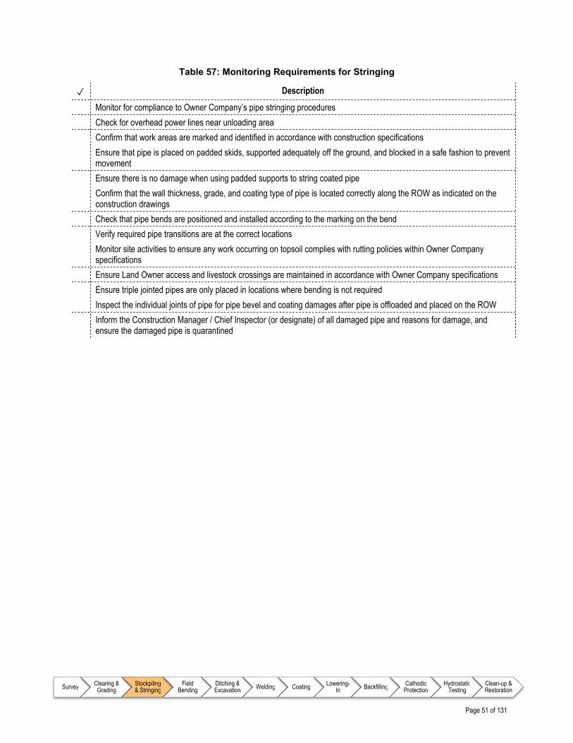
Page 51 of 131
Survey Clearing & Grading
Stockpiling & Stringing
Field Bending
Ditching & Excavation Welding Coating Lowering-
In Backfilling Cathodic Protection
Hydrostatic Testing
Clean-up & Restoration
Table 57: Monitoring Requirements for Stringing
✓ Description
Monitor for compliance to Owner Company’s pipe stringing procedures
Check for overhead power lines near unloading area
Confirm that work areas are marked and identified in accordance with construction specifications
Ensure that pipe is placed on padded skids, supported adequately off the ground, and blocked in a safe fashion to prevent movement
Ensure there is no damage when using padded supports to string coated pipe
Confirm that the wall thickness, grade, and coating type of pipe is located correctly along the ROW as indicated on the construction drawings
Check that pipe bends are positioned and installed according to the marking on the bend
Verify required pipe transitions are at the correct locations
Monitor site activities to ensure any work occurring on topsoil complies with rutting policies within Owner Company specifications
Ensure Land Owner access and livestock crossings are maintained in accordance with Owner Company specifications
Ensure triple jointed pipes are only placed in locations where bending is not required
Inspect the individual joints of pipe for pipe bevel and coating damages after pipe is offloaded and placed on the ROW
Inform the Construction Manager / Chief Inspector (or designate) of all damaged pipe and reasons for damage, and ensure the damaged pipe is quarantined

Page 52 of 131
Survey Clearing & Grading
Stockpiling & Stringing
Field Bending
Ditching & Excavation Welding Coating Lowering-
In Backfilling Cathodic Protection
Hydrostatic Testing
Clean-up & Restoration
9.7 Typical Outputs for Stockpiling and Stringing Inspection
Table 58: Typical Reporting Requirements
✓ Description
General
There are no incremental specific reporting requirements beyond those identified in chapter 6.0 Pipeline Construction Inspector – Foundational Information
Daily
Complete stockpiling and stringing progress reports, including: Work completed to date, including:
o Start and end chainages / station numbers of strung pipe and the pipe wall thickness o Start and end chainages / station numbers of locations where pipe was not strung and reasons for
skipping o Station numbers, joint numbers, wall thickness, coating types, and heat numbers when offloading on the
right of way (ROW) o Damage occurred to the pipe during stringing and mark the damaged locations on the pipe o Actual hours of work utilized for labor and equipment o Number of transport loads transported o Conditions that enhanced or delayed the planned progress of the day o Completed and signed Pipe Tally Sheets o Custody Transfer Forms o Any ROW weather / logistical conditions that caused either an increase or decrease in expected
progress

Page 53 of 131
Survey Clearing & Grading
Stockpiling & Stringing
Field Bending
Ditching & Excavation Welding Coating Lowering-
In Backfilling Cathodic Protection
Hydrostatic Testing
Clean-up & Restoration
References – Stockpiling and Stringing
Note to user: The reference information provided in Table 59 is intended as a guide only (i.e., the list is not exhaustive); documents of this nature are updated frequently and it remains the responsibility of the user to ensure that the correct, and most current, documents are referenced as appropriate.
Table 59: List of References – Stockpiling and Stringing
Document No. Type Title
American Petroleum Institute (API)
API 5L1 Recommended Practice Recommended Practice for Railway Transportation of Line Pipe
API 5LT Recommended Practice Recommended Practice for Truck Transportation of Line Pipe
API 5LW Recommended Practice Recommended Practice for Transportation of Line Pipe on Barges and Marine Vessels
Canadian Standards Association (CSA)
C22.3 No. 6 Recommended Practice Principles and Practices of Electrical Coordination Between Pipelines and Electric Supply Lines
ENFORM
N/A Report Sideboom Operator Training Standard (Entry Level)

Page 54 of 131
Survey Clearing & Grading
Stockpiling & Stringing
Field Bending
Ditching & Excavation Welding Coating Lowering-
In Backfilling Cathodic Protection
Hydrostatic Testing
Clean-up & Restoration
Page 55 of 131
Survey Clearing & Grading
Stockpiling & Stringing
Field Bending
Ditching & Excavation Welding Coating Lowering-
In Backfilling Cathodic Protection
Hydrostatic Testing
Clean-up & Restoration
10.0 FIELD BENDING
10.1 Overview
Field bending is an integral part of pipeline construction, and refers to the set of activities associated with bending the pipe in the field so that it fits the shape of the ROW and trench. Field bending is also known as “cold” bending since the pipe is not heated before the operation; because of this, there are strict limits on how much the pipe can be shaped. In cases where it is anticipated that the pipe will need a bend greater than technical specifications for field bends allow, the Owner Company will specify hot bends or fittings which it will purchase separately.
10.2 Inputs
As part of preparing for inspection during the field bending process, the Inspector will continually familiarize themselves with relevant aspects of key documents, drawings, and Owner Company technical specifications as identified in Table 61.
10.3 Execution
While the work is being executed, the Inspector is required to monitor workmanship and report on progress on a periodic basis. Typical items that the Inspector will monitor for during the field bending process are identified in a series of checklists as detailed in Table 60.
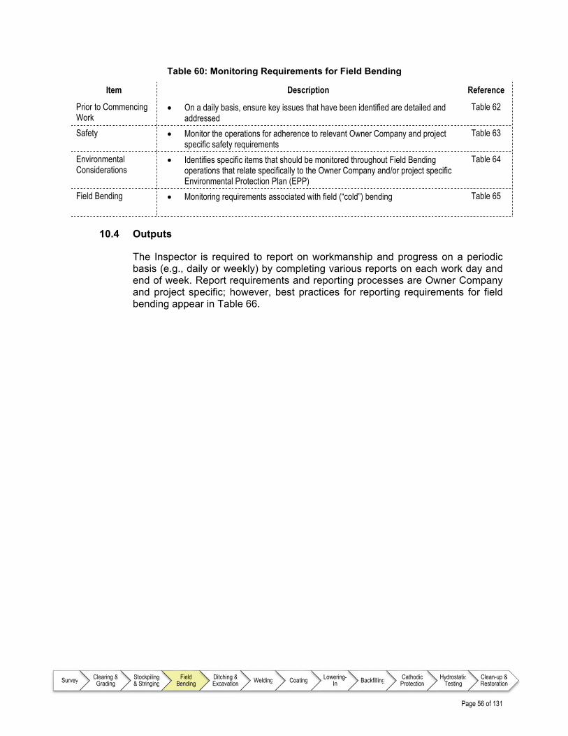
Page 56 of 131
Survey Clearing & Grading
Stockpiling & Stringing
Field Bending
Ditching & Excavation Welding Coating Lowering-
In Backfilling Cathodic Protection
Hydrostatic Testing
Clean-up & Restoration
Table 60: Monitoring Requirements for Field Bending
Item Description Reference
Prior to Commencing Work
On a daily basis, ensure key issues that have been identified are detailed and addressed
Table 62
Safety Monitor the operations for adherence to relevant Owner Company and project specific safety requirements
Table 63
Environmental Considerations
Identifies specific items that should be monitored throughout Field Bending operations that relate specifically to the Owner Company and/or project specific Environmental Protection Plan (EPP)
Table 64
Field Bending Monitoring requirements associated with field (“cold”) bending Table 65
10.4 Outputs
The Inspector is required to report on workmanship and progress on a periodic basis (e.g., daily or weekly) by completing various reports on each work day and end of week. Report requirements and reporting processes are Owner Company and project specific; however, best practices for reporting requirements for field bending appear in Table 66.

Page 57 of 131
Survey Clearing & Grading
Stockpiling & Stringing
Field Bending
Ditching & Excavation Welding Coating Lowering-
In Backfilling Cathodic Protection
Hydrostatic Testing
Clean-up & Restoration
Detailed Checklists – Field Bending
10.5 Typical Input Requirements for Field Bending Inspection
Table 61: Information Requirements for Field Bending
✓ Description
All designs, drawings, and specifications developed by the Owner Company and Contractors related to field bending, such as: Bill of Materials (BOM) Alignment Sheets Pipe Tallies Specifications detailing acceptable size and nature of pipe and coating defects Specifications detailing acceptable repair methods and practices for pipe and coating defects
Contracts and agreements related to: Transport and Handling of Materials Inspection of Materials Materials Storage
Permits related to: Road Transport
Owner Company specific Safety Plan, including (but not limited to): Handling of Materials
Project specific Environmental Protection Plan (EPP) detailing field bending requirements
Other project specific Plans, which may include: Traffic Control Plan

Page 58 of 131
Survey Clearing & Grading
Stockpiling & Stringing
Field Bending
Ditching & Excavation Welding Coating Lowering-
In Backfilling Cathodic Protection
Hydrostatic Testing
Clean-up & Restoration
10.6 Best Practice Items for Inspecting Typical Field Bending Operations
Table 62: Prior to Commencing Work
✓ Description
Ensure limitations and requirements for field bending operations defined by codes /standards and Owner Company specifications (i.e., whichever is most restrictive) are understood and clearly communicated based on the relevant jurisdiction, pipe material, and diameter
Identify any Owner Company requirements for completing test bends
During winter, confirm if Owner Company has identified ambient temperature limits for pipe bending operations (i.e., extreme cold weather may compromise structural integrity of pipe or coating during field bending operations)
Confirm that the appropriate instruments are available for inspecting bends (e.g., protractor, measuring tape, centre finder, caliper, and straight edge)
Table 63: Safety Concerns for Field Bending
✓ Description
There are no incremental specific Safety Concerns beyond those identified in chapter 6.0 Pipeline Construction Inspector – Foundational Information
Table 64: Typical Monitoring Requirements for Environmental Considerations
✓ Description
There are no incremental specific Environmental Considerations beyond those identified in chapter 6.0 Pipeline Construction Inspector – Foundational Information
Table 65: Typical Monitoring Requirements for Field Bending
✓ Description
Confirm that all field bends adhere to limitations and requirements for field bending operations based on the relevant jurisdiction, pipe material, and diameter
During winter, ensure any relevant Owner Company restrictions on bending operations based on ambient temperature are adhered to (i.e., extreme cold weather may compromise structural integrity of pipe or coating during field bending operations)
Confirm that field bends do not introduce compressive or tensile stresses (i.e., neutral axis of pipe does not deviate beyond values specified in code), excluding spiral welded pipe
Witness and confirm the success of any test bends required by Owner Company specifications
Ensure that field bends are the minimum specified distance from circumferential welds or open end of the pipe as specified by the Owner Company
Ensure that bending increments are distributed along the length of the bend
Ensure size and location of bends is established such that the pipe confirms to the centerline of the trench within limits prescribed by Owner Company
Confirm bends and elbows are strung in the correct sequence and orientation
Confirm that pipe (including pipe coating) was not damaged during field bending operations
Ensure that any pipe that does not meet Owner Company specifications (i.e., has gouges, buckles or unacceptable wrinkles, ripples, or ovality) is rejected, clearly marked, and removed from the right of way (ROW)

Page 59 of 131
Survey Clearing & Grading
Stockpiling & Stringing
Field Bending
Ditching & Excavation Welding Coating Lowering-
In Backfilling Cathodic Protection
Hydrostatic Testing
Clean-up & Restoration
10.7 Typical Outputs for Field Bending Inspection
Table 66: Typical Reporting Requirements
✓ Description
General
There are no incremental specific reporting requirements beyond those identified in chapter 6.0 Pipeline Construction Inspector – Foundational Information
Daily
Complete field bending progress reports, including: Work completed to date, including:
o Start and end chainages / station numbers of completed bending and set-up activities o Start and end chainages / station numbers of locations where pipe was not bent and reasons for
skipping o Number and types of bends made o For each bend: joint numbers, wall thickness, coating types, and heat numbers o Damage occurred to the pipe during bending and mark the damaged locations on the pipe o Actual hours of work utilized for labor and equipment o Conditions that enhanced or delayed the planned progress of the day o As-built information of the bends o Locations, quantities of unit price pay items, and extra work installed or utilized during bending
including locations of field bends made to replace 3D (radius) and 5D (radius) fittings and vice-versa
Page 60 of 131
Survey Clearing & Grading
Stockpiling & Stringing
Field Bending
Ditching & Excavation Welding Coating Lowering-
In Backfilling Cathodic Protection
Hydrostatic Testing
Clean-up & Restoration
References – Field Bending
Note to user: The reference information provided in Table 67 is intended as a guide only (i.e., the list is not exhaustive); documents of this nature are updated frequently and it remains the responsibility of the user to ensure that the correct, and most current, documents are referenced as appropriate.
Table 67: List of References – Field Bending
Document No. Type Title
There are no incremental specific reference documents beyond those identified in chapter 6.0 Pipeline Construction Inspector – Foundational Information

Page 61 of 131
Survey Clearing & Grading
Stockpiling & Stringing
Field Bending
Ditching & Excavation Welding Coating Lowering-
In Backfilling Cathodic Protection
Hydrostatic Testing
Clean-up & Restoration
11.0 DITCHING AND EXCAVATION
11.1 Overview
Ditching and excavation is the next phase of pipeline construction, and typically involves excavation of a trench in the right of way (ROW) for pipe installation. Typically, the ditching operations are after stringing, bending, welding, non-destructive examination (NDE), and coating due to the risk of having an open trench; however, there are a number of exceptions, including:
Where rock is encountered, the trench may be blasted and excavated prior to stringing
In urban areas or other areas where numerous underground utilities and obstructions may exist
It should be noted that ditching and excavation is still required for entry and exit pits for trenchless crossings. A mechanical wheel ditcher / trencher or backhoe with a trencher is generally used to create a trench of uniform depth and width; however, more specialized techniques and equipment may be required based on the type of soil and pipe. For example:
Backhoes or traditional excavators may be used for points of intersection
Wet areas where buoyancy control of the pipe requires an extra wide trench (to accommodate placing weights over the pipe)
Road, highway, railroad, Third Party pipelines, and river crossings
At all tie-in locations where extra width and depth are required for Welders to work in the trench
Areas with unsuitable / unstable soil conditions where trench sides need to be sloped (e.g., sandy soil)
Mountainous / steep slope and rocky soil / rock conditions
Short sections of pipe and/or areas where moving equipment around is not practical
Depending on the nature of buoyancy control requirements, trench work may be required and be undertaken within this phase of construction.
11.2 Inputs
As part of preparing for inspection during the ditching and excavation process, the Inspector will continually familiarize themselves with relevant aspects of key documents, drawings, and Owner Company technical specifications as identified in Table 69.

Page 62 of 131
Survey Clearing & Grading
Stockpiling & Stringing
Field Bending
Ditching & Excavation Welding Coating Lowering-
In Backfilling Cathodic Protection
Hydrostatic Testing
Clean-up & Restoration
11.3 Execution
While the work is being executed, the Inspector is required to monitor workmanship and report on progress on a periodic basis. Typical items that the Inspector will monitor for during the ditching and excavation process are identified in a series of checklists as detailed in Table 68.
Table 68: Monitoring Requirements for Ditching and Excavation
Item Description Reference
Prior to Commencing Work
On a daily basis, ensure key issues that have been identified are detailed and addressed
Table 70
Safety Monitor the operations for adherence to relevant Owner Company and project specific safety requirements
Table 71
Environmental Considerations
Identifies specific items that should be monitored throughout Ditching and Excavation operations that relate specifically to the Owner Company and/or project specific Environmental Protection Plan (EPP)
Table 72
Excavation Equipment
Monitor the operations for adherence to relevant Owner Company and project specific requirements; in particular, ensure that equipment does not damage pipe, buried facilities, or roadways in any way
Table 73
Trench Excavation Ensure that the trench is excavated to project requirements, including: o Specifications for alignment of centerline and dimensions of slope of
sides, width, and depth o Installation of gaps / plugs for Land Owner for livestock and wildlife
crossings o Installation of padding and buoyancy controls in preparation for
lowering-in
Table 74
Trenching through Rock
In rocky areas, blasting is required to break and loosen the rock to create a trench in areas where a trench cannot be excavated with backhoes, ditchers, or rippers. This is a particularly dangerous aspect of the operation due of the use of explosives; Inspectors will ensure that the Blasting Plan is followed without exception
Table 75
Crossing Underground Facilities (Encroachment)
A new pipeline will be constructed either under or over existing facilities (depending on their depths of cover), so the Inspector needs to ensure that crossing / encroachment agreements are followed and appropriate (i.e., hand trenching or hydrovac) near buried facilities
Table 76
Ditch Plugs and Sub-drains / Drain Tiles
Ensure that drainage and erosion control devices or measures, such as ditch plugs and sub-drains (drainage systems that divert water away from the trench bottom) / drain tiles (perforated tubing that allows water to enter and be drained away from the pipeline) to prevent erosion of the right of way (ROW) / trench due to ground and surface water, are used as per Owner Company specifications
Table 77
Seasonal (Winter) Considerations
Itemizes considerations that are specific to the construction season Table 78
Addressing Additional Work
Identifies items of particular note during this phase of the operation that can result in additional costs and therefore require close monitoring for contractual / cost reasons
Table 79

Page 63 of 131
Survey Clearing & Grading
Stockpiling & Stringing
Field Bending
Ditching & Excavation Welding Coating Lowering-
In Backfilling Cathodic Protection
Hydrostatic Testing
Clean-up & Restoration
Item Description Reference
Historic Sites In a conscious effort to preserve history, ditching and excavating operations will be suspended upon discovery of historic sites or resources until formal notice is received from Owner Company to recommence construction
Table 80
11.4 Outputs
The Inspector is required to report on workmanship and progress on a periodic basis (e.g., daily or weekly) by completing various reports on each work day and end of week. Report requirements and reporting processes are Owner Company and project specific; however, best practices for reporting requirements for ditching and excavation appear in Table 81.

Page 64 of 131
Survey Clearing & Grading
Stockpiling & Stringing
Field Bending
Ditching & Excavation Welding Coating Lowering-
In Backfilling Cathodic Protection
Hydrostatic Testing
Clean-up & Restoration
Detailed Checklists – Ditching and Excavation
11.5 Typical Input Requirements for Ditching and Excavation Inspection
Table 69: Information Requirements for Ditching and Excavation
✓ Description
All designs, drawings, and specifications developed by the Owner Company and Contractors related to ditching and excavation, such as: Access Road Drawings Line List (e.g., special concerns for each Land Owner) Trenching Specifications and Procedures Buoyancy Control Requirements Topsoil Segregation Requirements Pipeline Depth of Cover Requirements Blasting Specification (if required)
Contracts and agreements related to: Road Use Crossings for Buried Facilities Construction Survey
Permits related to: Environmental Road Use
Owner Company specific Safety Plan, including (but not limited to): Excavation Plan Traffic Control Plan Requirements for Personal Protective Equipment (PPE) Emergency Medical Services (EMS)
Project specific Environmental Protection Plan (EPP) detailing ditching and excavation requirements for the following (but not limited to): Watercourses Wetlands, muskeg, and swamp areas Wildlife habitats Migratory routes
Other project specific Plans, which may include: Blasting Plan Fire Prevention / Firefighting Plan Heritage Sites Engineered Shoring and Dewatering plans (as required)

Page 65 of 131
Survey Clearing & Grading
Stockpiling & Stringing
Field Bending
Ditching & Excavation Welding Coating Lowering-
In Backfilling Cathodic Protection
Hydrostatic Testing
Clean-up & Restoration
11.6 Best Practice Items for Inspecting Typical Ditching and Excavation Operations
Table 70: Prior to Commencing Work
✓ Description
Participate in daily meetings to address: Job safety and/or hazard identification issues Environmental concerns Duties of Inspector(s) Pipeline Contractor’s tailgate meetings (as required) Ad-hoc meetings with Contractors to discuss and clarify questions or concerns
Confirm everyone understands start and stop orders and signaling for equipment operation
Ensure exclusion zones are established and site personnel are aware of the boundaries
Crossing underground facilities including Third Party pipelines, power cables, communications cables, cables for cathodic protection purposes, and all public works will be identified, surveyed, and staked prior to any ground disturbance
The Owner Company of a Third Party facility may locate, expose and excavate the facility themselves or allow the Contractor to do so (according to the Owner Company’s procedures, specifications, and the crossing agreement). However, before the crossing construction begins, the existing buried utilities should be positively located
Equipment: Confirm all Equipment Operators have appropriate certification(s) / ticket(s) Confirm Contractor possesses Manufacturer information / manual of the machinery operated
Work area: Check that Third Party pipeline crossing ramps have been built Check that warning signs and temporary fencing is installed on open excavations close to public accesses Ensure that all necessary hand or hydrovac excavations of buried facilities and Third Party pipelines have been
carried out in advance of trenching activities
Table 71: Safety Concerns for Ditching and Excavation
✓ Description
Ensure One Calls / 811 Calls for underground facilities are made by the Contractor and ensure that a valid One Call / 811 Call ticket is in place in advance of commencing work
Ensure Equipment Operators use spotters while traversing under powerlines and overhead hazards
Ensure Equipment Operators make eye contact with other Equipment Operators before approaching
Monitor, where applicable, that the Contractor follows the excavation checklist (i.e., are aware of the hazards, roles, and responsibilities associated with excavation equipment and operation)
Confirm that Equipment Operators follow start and stop orders and proper signaling for equipment operation
Be aware of boot leg holes and their impact (undetonated dynamite which can explode) when excavating rock ditch
Confirm that Equipment Operators are working only in the exclusion zone and know the boundaries
Shut down work immediately if any unauthorized personnel enters the exclusion zone
Ensure that all lifting equipment (e.g., slings and cables) is inspected for damage, issues, and wear, and all findings are documented before use
Observe any specific requirements related to the jurisdiction (e.g., Occupational Safety and Health Administration (OSHA))

Page 66 of 131
Survey Clearing & Grading
Stockpiling & Stringing
Field Bending
Ditching & Excavation Welding Coating Lowering-
In Backfilling Cathodic Protection
Hydrostatic Testing
Clean-up & Restoration
✓ Description
Blasting
Confirm pre-blast survey has been completed
Confirm an approved Blasting Plan is in place
Ensure that the Contractor has obtained permits for the use and storage of explosives
Check that only qualified drilling and blasting personnel are employed in the blasting operations
Ensure the Contractor has seismic monitoring equipment for blasting in place to monitor Peak Particle Velocity (PPV) limits
Ensure blasting notifications are in place and are being clearly communicated
Monitor for loose rock scattering onto the ROW, adjacent land, or causing damage to equipment / property
Verify that the Contractor picks up and properly disposes of any fly-rock from blasting activities
Ensure that segments being prepared for blasting have matting to protect the impact of fly-rock during the blast
Establish and maintain adequate set-back distances for all blasting personnel and non-essential personnel
Table 72: Typical Monitoring Requirements for Environmental Considerations
✓ Description
Monitor and record trenching and spoil pile segregation for subsoils with variable horizons
Table 73: Typical Monitoring Requirements for Excavation Equipment
✓ Description
Ensure that if a machine strikes, contacts, is bogged down, slides into, or rests on top of a pipeline facility, work is stopped immediately and the Construction Manager / Chief Inspector (or designate) is notified; the machine is not to be moved or extricated without Owner Company approval
Ensure that the Contractor never passes the bucket over an exposed, loaded pipeline during excavation
Inspect backfill areas for soft spots, rock, and adequate depth of cover before heavy equipment crosses a loaded line Confirm the use of timber mats for equipment support in areas of weak and saturated soils Ensure roadways are protected from tracked equipment at road crossings
Table 74: Typical Monitoring Requirements for Trench Excavating
✓ Description
Trench Dimensions
Periodically measure minimum trench dimensions to conform with specifications as defined in construction alignment sheets
Confirm that the specified depth of cover will be measured from the top of pipe to the graded ROW profile; in the event that grading was not required, confirm that the depth will be measured to the original stripped ground. Note: Topsoil cuts are not considered in the cover depth measurement
Where buoyancy control (e.g., continuous concrete coating, saddle weights, bolt-on weights, or screw anchors) are to be used, confirm that the depth of cover will be from the top of the buoyancy control measure
Confirm that farm, lot-line and midfield, seasonal, or other drains not shown on project drawings will be installed to a minimum cover depth specified
Confirm that depths of cover at the trench and drains will be measured from the top of the pipe to the invert of the ditch or drain

Page 67 of 131
Survey Clearing & Grading
Stockpiling & Stringing
Field Bending
Ditching & Excavation Welding Coating Lowering-
In Backfilling Cathodic Protection
Hydrostatic Testing
Clean-up & Restoration
✓ Description
Confirm that the trench will be deep enough to provide minimum cover in all conditions, including sand padding and sandbag or foam pillow supports (where necessary)
Confirm that the trench will be graded to the specified clearance at all crossings (i.e., road, ditch, culvert, cable, water main, and sewer) or any other obstruction as directed by Owner Company specifications
Monitor for locations where available work space is insufficient to allow compliance with safety and environmental requirements; escalate to Construction Manager / Chief Inspector (or designate) when identified
Open Trench Considerations
In cultivated fields or where livestock is present, ensure that safe, temporary bridges or backfilled sections along the trench are provided for livestock and farm machinery to cross as specified in construction drawings
Confirm the length of the trench left open during pipeline construction is approved by the Construction Manager / Chief Inspector (or designate) based on the stability of the trench and weather conditions
Ensure that the Contractor will not leave a trench open for extended periods; in particular, monitor for: Safety concerns for workers and wildlife (confirm gaps are left in adjacent spoil and slash windrows at wildlife
crossings, recreational trails, etc.) Large accumulations of water Excavated soil becoming frozen in winter Snow and ice accumulation
Buoyancy Control
Ensure trench keys (wider trench locations to accommodate buoyancy control weights) are excavated to specified dimensions and at appropriate locations based on the construction drawings
If screw anchors (steel helical anchors, installed in pairs on either side of the pipe through the trench bottom into the soil after the pipe section is lowered into the trench) are to be installed, ensure trench is adequately sloped per Owner Company specifications with access / egress ladders installed
Table 75: Typical Monitoring Requirements for Trenching through Rock
✓ Description
Check that mats or other safeguards are placed over the ditch line to prevent loose rocks from scattering onto and off the right of way (ROW)
Confirm that scattered rocks are disposed of by the Contractor to an authorized site off the right of way (ROW) or piled neatly in rows along the side of the right of way (ROW) as per line list
Confirm that the trench will be dug for an additional depth based on Owner Company specifications (i.e., greater than the minimum ditch depth shown on the drawings) to allow for trench bottom padding
Table 76: Typical Monitoring Requirements for Crossing Underground Facilities (Encroachment)
✓ Description
Ensure that the Contractor will excavate the trench at crossing locations with a gap between the underground facility and the proposed pipeline as specified in the contract documents / crossing agreements
Validate the locations of buried facilities after the Contractor exposes these by hand or the use of hydrovac tools prior to mechanical excavation
Observe the Contractor during the exposure of an operating pipeline and ensure compliance to project requirements (in case of potential inconsistency between the Owner Company’s specification, the construction contract, or the crossing agreement, the most stringent requirements will apply)
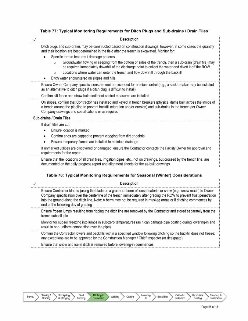
Page 68 of 131
Survey Clearing & Grading
Stockpiling & Stringing
Field Bending
Ditching & Excavation Welding Coating Lowering-
In Backfilling Cathodic Protection
Hydrostatic Testing
Clean-up & Restoration
Table 77: Typical Monitoring Requirements for Ditch Plugs and Sub-drains / Drain Tiles
✓ Description
Ditch plugs and sub-drains may be constructed based on construction drawings; however, in some cases the quantity and their location are best determined in the field after the trench is excavated. Monitor for: Specific terrain features / drainage patterns
o Groundwater flowing or seeping from the bottom or sides of the trench, then a sub-drain (drain tile) may be required immediately downhill of the discharge point to collect the water and divert it off the ROW
o Locations where water can enter the trench and flow downhill through the backfill Ditch water encountered on slopes and hills
Ensure Owner Company specifications are met or exceeded for erosion control (e.g., a sack breaker may be installed as an alternative to ditch plugs if a ditch plug is difficult to install)
Confirm silt fence and straw bale sediment control measures are installed
On slopes, confirm that Contractor has installed and keyed in trench breakers (physical dams built across the inside of a trench around the pipeline to prevent backfill migration and/or erosion) and sub-drains in the trench per Owner Company drawings and specifications or as required
Sub-drains / Drain Tiles
If drain tiles are cut: Ensure location is marked Confirm ends are capped to prevent clogging from dirt or debris Ensure temporary flumes are installed to maintain drainage
If unmarked utilities are discovered or damaged, ensure the Contractor contacts the Facility Owner for approval and requirements for the repair
Ensure that the locations of all drain tiles, irrigation pipes, etc., not on drawings, but crossed by the trench line, are documented on the daily progress report and alignment sheets for the as-built drawings
Table 78: Typical Monitoring Requirements for Seasonal (Winter) Considerations
✓ Description
Ensure Contractor blades (using the blade on a grader) a berm of loose material or snow (e.g., snow roach) to Owner Company specification over the centerline of the trench immediately after grading the ROW to prevent frost penetration into the ground along the ditch line. Note: A berm may not be required in muskeg areas or if ditching commences by end of the following day of grading
Ensure frozen lumps resulting from ripping the ditch line are removed by the Contractor and stored separately from the trench subsoil pile
Monitor for subsoil freezing into lumps in sub-zero temperatures (as it can damage pipe coating during lowering-in and result in non-uniform compaction over the pipe)
Confirm the Contractor lowers and backfills within a specified window following ditching so the backfill does not freeze; any exceptions are to be approved by the Construction Manager / Chief Inspector (or designate)
Ensure that snow and ice in ditch is removed before lowering-in commences

Page 69 of 131
Survey Clearing & Grading
Stockpiling & Stringing
Field Bending
Ditching & Excavation Welding Coating Lowering-
In Backfilling Cathodic Protection
Hydrostatic Testing
Clean-up & Restoration
Table 79: Typical Monitoring Requirements for Additional Work Items
✓ Description
Monitor and record the following additional work items, which have potential cost implications: Extra-depth ditch Locations where available work space is insufficient for compliance with safety and environmental requirements Pre-ripping attempts where subsurface rock is encountered that may require specialized mechanical excavation Rock-ditch excavation by specialized mechanical excavation techniques Rock-ditch excavation by blasting techniques Quantity of rock excavation (in accordance with the method of payment in the contract documents) Fabricated blasting mats used to contain fly-rock (where required by permit) Use of timber mats for equipment support in areas of weak and saturated soils Third Party utility crossings Sub-drain (drain tile) station locations and temporary / permanent repairs (if required)
Table 80: Typical Monitoring Requirements for Historic Sites
✓ Description
Immediately suspend ditching activity and notify the Construction Manager / Chief Inspector (or designate) if any historic sites or resources are discovered
Ensure ditching will not resume until formal notification provided by Construction Manager / Chief Inspector (or designate)

Page 70 of 131
Survey Clearing & Grading
Stockpiling & Stringing
Field Bending
Ditching & Excavation Welding Coating Lowering-
In Backfilling Cathodic Protection
Hydrostatic Testing
Clean-up & Restoration
11.7 Typical Outputs for Ditching and Excavation Inspection
Table 81: Typical Reporting Requirements
✓ Description
General
Record any weather or other logistical conditions that caused either an increase or decrease in expected progress
Daily
Complete ditching and excavation progress reports, including: Work completed to date, including:
o Record the quantities of any rock excavation o Record the ditch depths and widths o Start and end chainages / station numbers of dug trench o Record soil horizons o Locations of all drain tiles, irrigation pipes, etc., not on drawings, but crossed by the trench line
References – Ditching and Excavation
Note to user: The reference information provided in Table 82 is intended as a guide only (i.e., the list is not exhaustive); documents of this nature are updated frequently and it remains the responsibility of the user to ensure that the correct, and most current, documents are referenced as appropriate.
Table 82: List of References – Ditching and Excavation
Document No. Type Title
INGAA Foundation
CS-S-12 Guideline Construction Safety Consensus Guidelines – Trenching and Excavation Safety

Page 71 of 131
Survey Clearing & Grading
Stockpiling & Stringing
Field Bending
Ditching & Excavation Welding Coating Lowering-
In Backfilling Cathodic Protection
Hydrostatic Testing
Clean-up & Restoration
12.0 WELDING
12.1 Overview
Welding during pipeline construction is performed to join lengths of pipe together as the Construction crew moves along the pipeline right of way (ROW). Welding is a process that uses fusion to join two or more materials together to become a manufactured or fabricated item. In the pipeline industry, the arc welding process is used to join pipe to pipe, and pipe to components together to form a pipeline. While welding requires specialized expertise, not just for the execution of the work, but also inspection of the work, there are a number of items that the Inspector should be aware of as part of undertaking their role effectively (i.e., working alongside Welding Inspectors). Welding inspection should only be performed by a Welding Inspector who has been qualified and has been specifically assigned this task. As such, the information presented within this section deviates somewhat from the majority of chapters in this document and focuses on providing the Inspector with sufficient knowledge to understand the limitations of their role in the context of welding inspection.
12.2 Inputs
While the Inspector is not expected to undertake significant welding inspection activities, some indication of typical inputs is provided as orientation (i.e., background information). This information is detailed in Table 84.
12.3 Execution
While the work is being executed, the Inspector is required to monitor workmanship and report on progress on a periodic basis. Since welding inspection is a specialized role, the listing provided in this section is focused on items that would typically require specialized welding expertise (i.e., indication of items that would prompt the Inspector to escalate identified issues). Typical items that the Inspector will monitor for during the welding process are identified in a series of checklists as detailed in Table 83.

Page 72 of 131
Survey Clearing & Grading
Stockpiling & Stringing
Field Bending
Ditching & Excavation Welding Coating Lowering-
In Backfilling Cathodic Protection
Hydrostatic Testing
Clean-up & Restoration
Table 83: Monitoring Requirements for Welding
Item Description Reference
Prior to Commencing Work
On a daily basis, ensure key issues that have been identified are detailed and addressed
Table 85
Safety Monitor the operations for adherence to relevant Owner Company and project specific safety requirements
Table 86
Environmental Considerations
Identifies specific items that should be monitored throughout Welding Operations that relate specifically to the Owner Company and/or project specific Environmental Protection Plan (EPP)
Table 87
General Welding Operations
Typical monitoring requirements for a non-specialized Inspector. Note that it is important to identify those situations that require a specialized Welding Inspector
Table 88
12.4 Outputs
While general Inspectors may be asked to assist a Welding Inspector, they are not to perform welding inspection activities on their own. Some indication of typical outputs is provided as background information as detailed in Table 89.

Page 73 of 131
Survey Clearing & Grading
Stockpiling & Stringing
Field Bending
Ditching & Excavation Welding Coating Lowering-
In Backfilling Cathodic Protection
Hydrostatic Testing
Clean-up & Restoration
Detailed Checklists – Welding
12.5 Typical Input Requirements for Welding Inspection
Table 84: Information Requirements for Welding
✓ Description
All designs, drawings, and specifications developed by the Owner Company and Contractors related to welding, such as: All applicable Welding Procedure Specifications (WPS) All applicable Owner Company’s Welding Standards Alignment Sheets
Contracts and agreements related to: Welding
o All Welders’ qualifications records to specific applicable processes and WPS Non-Destructive Examination (NDE) Construction Survey
Permits related to: Environmental Road Use
Owner Company specific Safety Plan, including (but not limited to): Requirements for Personal Protective Equipment (PPE) Emergency Medical Services (EMS)
Project specific Environmental Protection Plan (EPP) detailing welding requirements
Other project specific Plans, which may include: Welding Plan
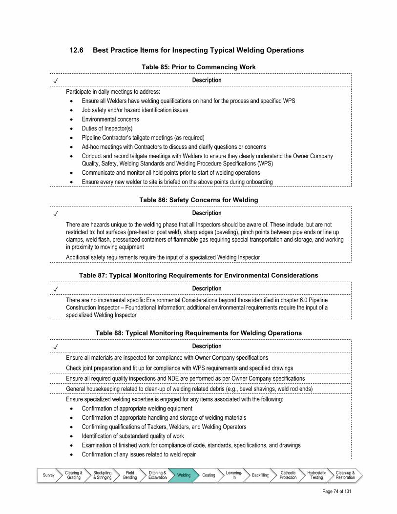
Page 74 of 131
Survey Clearing & Grading
Stockpiling & Stringing
Field Bending
Ditching & Excavation Welding Coating Lowering-
In Backfilling Cathodic Protection
Hydrostatic Testing
Clean-up & Restoration
12.6 Best Practice Items for Inspecting Typical Welding Operations
Table 85: Prior to Commencing Work
✓ Description
Participate in daily meetings to address: Ensure all Welders have welding qualifications on hand for the process and specified WPS Job safety and/or hazard identification issues Environmental concerns Duties of Inspector(s) Pipeline Contractor’s tailgate meetings (as required) Ad-hoc meetings with Contractors to discuss and clarify questions or concerns Conduct and record tailgate meetings with Welders to ensure they clearly understand the Owner Company
Quality, Safety, Welding Standards and Welding Procedure Specifications (WPS) Communicate and monitor all hold points prior to start of welding operations Ensure every new welder to site is briefed on the above points during onboarding
Table 86: Safety Concerns for Welding
✓ Description
There are hazards unique to the welding phase that all Inspectors should be aware of. These include, but are not restricted to: hot surfaces (pre-heat or post weld), sharp edges (beveling), pinch points between pipe ends or line up clamps, weld flash, pressurized containers of flammable gas requiring special transportation and storage, and working in proximity to moving equipment
Additional safety requirements require the input of a specialized Welding Inspector
Table 87: Typical Monitoring Requirements for Environmental Considerations
✓ Description
There are no incremental specific Environmental Considerations beyond those identified in chapter 6.0 Pipeline Construction Inspector – Foundational Information; additional environmental requirements require the input of a specialized Welding Inspector
Table 88: Typical Monitoring Requirements for Welding Operations
✓ Description
Ensure all materials are inspected for compliance with Owner Company specifications
Check joint preparation and fit up for compliance with WPS requirements and specified drawings
Ensure all required quality inspections and NDE are performed as per Owner Company specifications
General housekeeping related to clean-up of welding related debris (e.g., bevel shavings, weld rod ends)
Ensure specialized welding expertise is engaged for any items associated with the following: Confirmation of appropriate welding equipment Confirmation of appropriate handling and storage of welding materials Confirming qualifications of Tackers, Welders, and Welding Operators Identification of substandard quality of work Examination of finished work for compliance of code, standards, specifications, and drawings Confirmation of any issues related to weld repair

Page 75 of 131
Survey Clearing & Grading
Stockpiling & Stringing
Field Bending
Ditching & Excavation Welding Coating Lowering-
In Backfilling Cathodic Protection
Hydrostatic Testing
Clean-up & Restoration
12.7 Typical Outputs for Welding Inspection
Table 89: Typical Reporting Requirements
✓ Description
General
Safety Hazard Observation Report
Job Safety Analysis (JSA) / Hazard Identification Report
Non-Destructive Examination (NDE)
Radiographic Records
Visual Inspection Report(s)
NDE Results (e.g., radiographic film) and Supporting Records
NDE Personnel Qualification Reports
Welding
Welding Parameter Form
Mainline Welding Report
List of Qualified Welders’ Reports
Welding Coupon Test Reports
Tie-in and Poorboy (i.e., short section) Welding Report(s)
Fabrication Welding Report(s)
Weld Mapping
Other
Damaged Pipe Report
Non-pipe Material / Equipment Damage Report
Daily
Complete welding progress reports, including: Work completed to date, including:
o Number of front end / back end welds completed and the number of welds rejected on a daily basis o Start and end locations for the Welding crews o Owner Company specific Welding Inspection Forms
Any and all specific daily reports required by the Owner Company

Page 76 of 131
Survey Clearing & Grading
Stockpiling & Stringing
Field Bending
Ditching & Excavation Welding Coating Lowering-
In Backfilling Cathodic Protection
Hydrostatic Testing
Clean-up & Restoration
References – Welding
Note to user: The reference information provided in Table 90 is intended as a guide only (i.e., the list is not exhaustive); documents of this nature are updated frequently and it remains the responsibility of the user to ensure that the correct, and most current, documents are referenced as appropriate.
Table 90: List of References – Welding
Document No. Type Title
American National Standards Institute (ANSI)
ANSI Z49.1 Standard Safety in Welding, Cutting, and Allied Processes
American Petroleum Institute (API)
API Standard 1104 Standard Welding of Pipelines and Related Facilities
American Welding Society (AWS)
AWS QC1 Standard Standard for AWS Certification of Welding Inspectors
Canadian Standards Association (CSA)
CAN/CSA-W117.2 Standard Safety in Welding, Cutting, and Allied Processes
CSA W178.2 Standard Certification of Welding Inspectors
INGAA Foundation
N/A Action Plan / Best Practice Training Guidance for Welding & Coating Workers & Inspectors
N/A Action Plan / Best Practice Best Practices in Applying API 1104 Appendix A

Page 77 of 131
Survey Clearing & Grading
Stockpiling & Stringing
Field Bending
Ditching & Excavation Welding Coating Lowering-
In Backfilling Cathodic Protection
Hydrostatic Testing
Clean-up & Restoration
13.0 COATING
13.1 Overview
Coating of the pipeline provides a protective barrier against damage to the pipe (e.g., corrosion, scrapes). The majority of the coating operation occurs in a centralized plant; however, since individual pipe joints are welded together during the construction process, the (girth) weld area requires coating in the field. While coating requires specialized expertise, not just for the execution of the work, but also Inspection of the work, there are a number of items that the Inspector should be aware of as part of undertaking their role effectively (i.e., working alongside Coating Inspectors). As such, the information presented within this section deviates somewhat from the majority of chapters in this document and focuses on providing the Inspector with sufficient knowledge to understand the limitations of their role in the context of coating inspection.
13.2 Inputs
While the Inspector is not expected to undertake significant coating inspection activities, some indication of typical inputs is provided as orientation (i.e., background information). This information is detailed in Table 92.
13.3 Execution
While the work is being executed, the Inspector is required to monitor workmanship and report on progress on a periodic basis. Since coating inspection is a specialized role, the listing provided in this section is focused on items that would typically require specialized coating expertise (i.e., indication of items that would prompt the Inspector to escalate identified issues). Typical items that the Inspector will monitor for during the coating process are identified in a series of checklists as detailed in Table 91.

Page 78 of 131
Survey Clearing & Grading
Stockpiling & Stringing
Field Bending
Ditching & Excavation Welding Coating Lowering-
In Backfilling Cathodic Protection
Hydrostatic Testing
Clean-up & Restoration
Table 91: Monitoring Requirements for Coating
Item Description Reference
Prior to Commencing Work
On a daily basis, ensure key issues that have been identified are detailed and addressed
Table 93
Safety Monitor the operations for adherence to relevant Owner Company and project specific safety requirements
Table 94
Environmental Considerations
Identifies specific items that should be monitored throughout Coating Operations that relate specifically to the Owner Company and/or project specific Environmental Protection Plan (EPP)
Table 95
General Pipe Surface Preparation and Coating Operations
Typical monitoring requirements for a non-specialized Inspector. Note that it is important to identify those situations that require a specialized Coating Inspector
Ensure that all pipe coating damage has been identified and repaired prior to the physical lowering-in of pipe
Table 96
13.4 Outputs
While general Inspectors may be asked to assist a Coating Inspector, they are not to perform coating inspection activities on their own. Some indication of typical outputs is provided as background information as detailed in Table 97.

Page 79 of 131
Survey Clearing & Grading
Stockpiling & Stringing
Field Bending
Ditching & Excavation Welding Coating Lowering-
In Backfilling Cathodic Protection
Hydrostatic Testing
Clean-up & Restoration
Detailed Checklists – Coating
13.5 Typical Input Requirements for Coating Inspection
Table 92: Information Requirements for Coating
✓ Description
All designs, drawings, and specifications developed by the Owner Company and Contractors related to coating, such as: Coating Procedures Coating Specifications Alignment Sheets Manufacturer supplied information (e.g., storage and handling requirements) Material Safety Data Sheet (MSDS) for coating material
Contracts and agreements related to: Coating Non-Destructive Examination (NDE) Construction Survey
Permits related to: Environmental Road Use Safe Work
Owner Company specific Safety Plan, including (but not limited to): Requirements for Personal Protective Equipment (PPE) Emergency Medical Services (EMS)
Project specific Environmental Protection Plan (EPP) detailing coating requirements for the following (but not limited to): Watercourses Wetlands, muskeg, and swamp areas Wildlife habitats Migratory routes
Other project specific Plans, which may include: Coating Plan

Page 80 of 131
Survey Clearing & Grading
Stockpiling & Stringing
Field Bending
Ditching & Excavation Welding Coating Lowering-
In Backfilling Cathodic Protection
Hydrostatic Testing
Clean-up & Restoration
13.6 Best Practice Items for Inspecting Typical Coating Operations
Table 93: Prior to Commencing Work
✓ Description
Participate in daily meetings to address: Job safety and/or hazard identification issues Environmental concerns Duties of Inspector(s) Pipeline Contractor’s tailgate meetings (as required) Ad-hoc meetings with Contractors to discuss and clarify questions or concerns
Verify that blasting medium and coating materials are approved
Table 94: Safety Concerns for Coating
✓ Description
Ensure whip checks are installed on hoses
Ensure protection is in place to prevent blast media from entering valves, pipe, fittings and appurtenances
Ensure specialized Coating Inspector is engaged to identify additional safety requirements
Table 95: Typical Monitoring Requirements for Environmental Considerations
✓ Description
Review site specific requirements for blast media. Silica based media may require specialized disposal methods
Ensure specialized Coating Inspector is engaged to identify additional environmental requirements
Table 96: Typical Monitoring Requirements for General Pipe Surface Preparation and Coating Operations
✓ Description
Ensure all materials are handled and stored as per Manufacturer and Owner Company specifications
Ensure all materials being used match Owner Company specifications
Ensure materials are not expired per Manufacturer expiry date(s)
Ensure all containers for coating material are in good condition and not damaged in any way
Ensure that all required x-rays are completed before applying protective coatings
Ensure all jeep equipment settings are appropriate for different thicknesses of coating
Monitor holiday detection activities for compliance to Owner Company requirements
Monitor continually Construction Contractor supplied jeeping / holiday detectors (instruments that use electricity to locate coating discontinuities) to ensure that detectors are set at correct voltage and have proper grounding
Check all weld joints for holidays after being coated
Confirm that all coating defects are marked, repaired, and pipe sections re-jeeped before lowering-in pipe
Confirm that holidaying/jeeping is conducted immediately behind the rear lowering-in cradle (sling assemblies with rollers that a sideboom uses to lift the pipe section) for coating damage from rollers
Ensure that coating repairs are completed in accordance with the project coating standards
General housekeeping of coating related debris (e.g., gloves, brushes, rollers, containers, overspray)

Page 81 of 131
Survey Clearing & Grading
Stockpiling & Stringing
Field Bending
Ditching & Excavation Welding Coating Lowering-
In Backfilling Cathodic Protection
Hydrostatic Testing
Clean-up & Restoration
✓ Description
Identify situations that require specialized coating expertise is required for any items associated with the following: Confirming qualifications of Coating Applicators Confirming appropriate pre heat temperatures around circumference of pipe Confirmation that coatings are only applied within the surface, weather and atmospheric requirements of Owner
Company Specifications and the Manufacturer’s specifications Ensure that surface profile is checked for compliance with Owner Specifications and recorded (i.e., anchor
profile specifications (pipe surface roughness / pattern that achieves maximum coating adhesion) Identification of substandard quality of work Examination of finished work for compliance of code, standards, specifications and drawings Interpretation of specifications and codes Confirmation of any issues related to coating repair

Page 82 of 131
Survey Clearing & Grading
Stockpiling & Stringing
Field Bending
Ditching & Excavation Welding Coating Lowering-
In Backfilling Cathodic Protection
Hydrostatic Testing
Clean-up & Restoration
13.7 Typical Outputs for Coating Inspection
Table 97: Typical Reporting Requirements
✓ Description
General
Record any weather or other logistical conditions that caused either an increase or decrease in expected progress
Record holiday detector settings and calibration results per Owner Company Forms
Ensure completion of as-built red-lined drawings
Daily
Complete coating progress reports, including: Work completed to date, including:
o Conditions of the coating product containers o Number and types of coating products o Names of the Manufacturers of coating products o Color of coating products o Batch and/or lot numbers of coating products o Shelf life of coating products in use o Holiday test results o Anchor profiles o Dry film thickness of all layers in the coating system o Quality of workmanship o Owner Company specific Coating Inspection Forms o Start and end points for completed coating distances o Start and end points for skipped locations and why they were not completed

Page 83 of 131
Survey Clearing & Grading
Stockpiling & Stringing
Field Bending
Ditching & Excavation Welding Coating Lowering-
In Backfilling Cathodic Protection
Hydrostatic Testing
Clean-up & Restoration
References – Coating
Note to user: The reference information provided in Table 98 is intended as a guide only (i.e., the list is not exhaustive); documents of this nature are updated frequently and it remains the responsibility of the user to ensure that the correct, and most current, documents are referenced as appropriate.
Table 98: List of References – Coating
Document No. Type Title
Canadian Standards Association (CSA)
CSA Z245.20 Standard Fusion Bond Epoxy (FBE) Coatings
CSA Z245.21 Standard Polyethylene Coatings
CSA Z245.22 Standard Polyethylene Foam Insulation Coatings
INGAA Foundation
N/A Action Plan / Best Practice Field Applied Coatings Best Practices
NACE International
SP0185 Standard Extruded Polyolefin Resin Coating Systems with Soft Adhesives for Underground or Submerged Pipe
SP0188 Standard Discontinuity (Holiday) Testing of New Protective Coatings on Conductive Substrates
SP0490 Standard Holiday Detection of Fusion-Bonded Epoxy External Coatings of 250 to 760µm (10 to 30mil)

Page 84 of 131
Survey Clearing & Grading
Stockpiling & Stringing
Field Bending
Ditching & Excavation Welding Coating Lowering-
In Backfilling Cathodic Protection
Hydrostatic Testing
Clean-up & Restoration
Page 85 of 131
Survey Clearing & Grading
Stockpiling & Stringing
Field Bending
Ditching & Excavation Welding Coating Lowering-
In Backfilling Cathodic Protection
Hydrostatic Testing
Clean-up & Restoration
14.0 LOWERING-IN
14.1 Overview
Lowering-in refers to preparing the trench base (if required, due to presence of rock or stones), picking the pipe up from its temporary supports off the right of way (ROW) and placing it into an excavated trench after welding, non-destructive examination (NDE - a group of analysis techniques used in industry to evaluate the properties of a weld without causing damage), coating of pipe joints, and completing any associated coating repairs. The main focus is to monitor pipe and coating integrity during the lowering-in operation. A considerable amount of planning and skill is required to lift the pipe using sidebooms (a bulldozer wheel or crawler tractor that incorporates a crane attachment off the left side, allowing for lifting a continuous length of pipe and placing it in the trench) and other machinery. The size, number, and spacing of sidebooms have to be calculated to ensure the pipe is not under excessive stress and equipment stability is maintained under the lowering-in process.
14.2 Inputs
As part of preparing for inspection during the lowering-in process, the Inspector will continually familiarize themselves with relevant aspects of key documents, drawings, and Owner Company technical specifications as identified in Table 100.
14.3 Execution
While the work is being executed, the Inspector is required to monitor workmanship and report on progress on a periodic basis. Typical items that the Inspector will monitor for during the lowering-in process are identified in a series of checklists as detailed in Table 99.
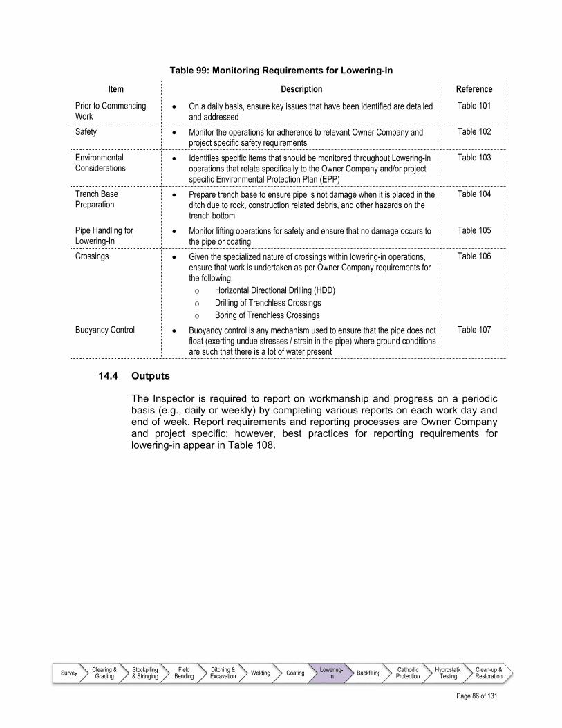
Page 86 of 131
Survey Clearing & Grading
Stockpiling & Stringing
Field Bending
Ditching & Excavation Welding Coating Lowering-
In Backfilling Cathodic Protection
Hydrostatic Testing
Clean-up & Restoration
Table 99: Monitoring Requirements for Lowering-In
Item Description Reference
Prior to Commencing Work
On a daily basis, ensure key issues that have been identified are detailed and addressed
Table 101
Safety Monitor the operations for adherence to relevant Owner Company and project specific safety requirements
Table 102
Environmental Considerations
Identifies specific items that should be monitored throughout Lowering-in operations that relate specifically to the Owner Company and/or project specific Environmental Protection Plan (EPP)
Table 103
Trench Base Preparation
Prepare trench base to ensure pipe is not damage when it is placed in the ditch due to rock, construction related debris, and other hazards on the trench bottom
Table 104
Pipe Handling for Lowering-In
Monitor lifting operations for safety and ensure that no damage occurs to the pipe or coating
Table 105
Crossings Given the specialized nature of crossings within lowering-in operations, ensure that work is undertaken as per Owner Company requirements for the following: o Horizontal Directional Drilling (HDD) o Drilling of Trenchless Crossings o Boring of Trenchless Crossings
Table 106
Buoyancy Control Buoyancy control is any mechanism used to ensure that the pipe does not float (exerting undue stresses / strain in the pipe) where ground conditions are such that there is a lot of water present
Table 107
14.4 Outputs
The Inspector is required to report on workmanship and progress on a periodic basis (e.g., daily or weekly) by completing various reports on each work day and end of week. Report requirements and reporting processes are Owner Company and project specific; however, best practices for reporting requirements for lowering-in appear in Table 108.
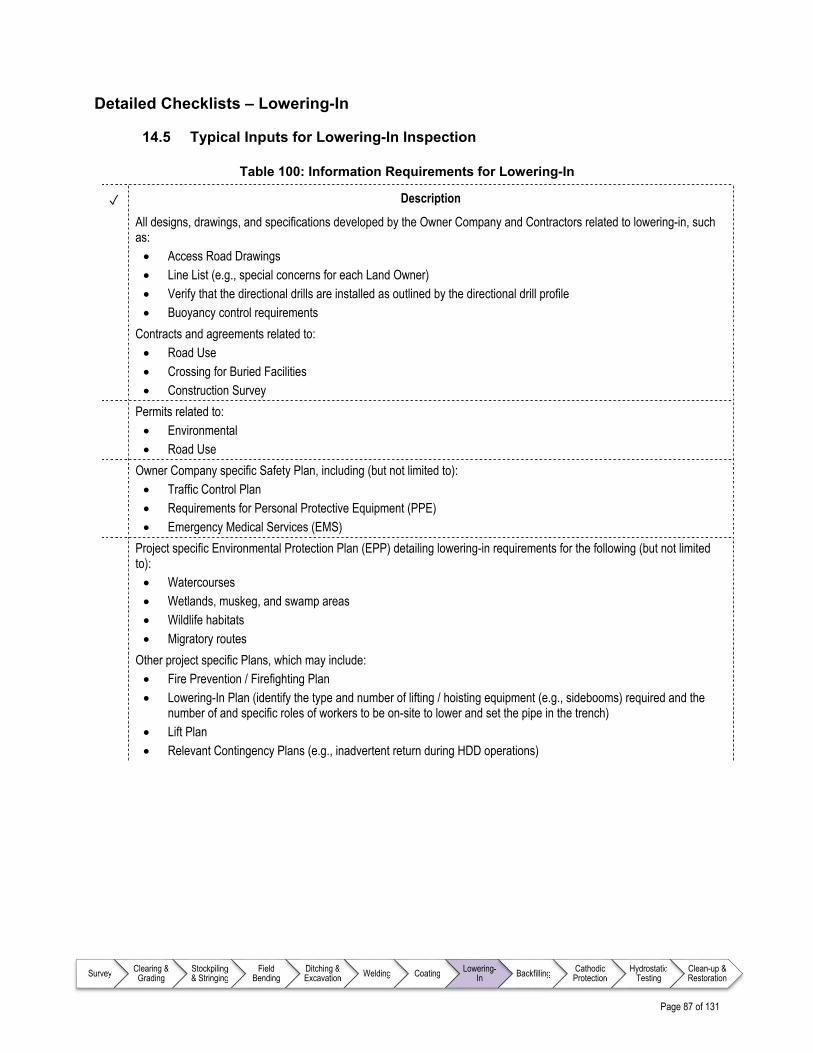
Page 87 of 131
Survey Clearing & Grading
Stockpiling & Stringing
Field Bending
Ditching & Excavation Welding Coating Lowering-
In Backfilling Cathodic Protection
Hydrostatic Testing
Clean-up & Restoration
Detailed Checklists – Lowering-In
14.5 Typical Inputs for Lowering-In Inspection
Table 100: Information Requirements for Lowering-In
✓ Description
All designs, drawings, and specifications developed by the Owner Company and Contractors related to lowering-in, such as: Access Road Drawings Line List (e.g., special concerns for each Land Owner) Verify that the directional drills are installed as outlined by the directional drill profile Buoyancy control requirements
Contracts and agreements related to: Road Use Crossing for Buried Facilities Construction Survey
Permits related to: Environmental Road Use
Owner Company specific Safety Plan, including (but not limited to): Traffic Control Plan Requirements for Personal Protective Equipment (PPE) Emergency Medical Services (EMS)
Project specific Environmental Protection Plan (EPP) detailing lowering-in requirements for the following (but not limited to): Watercourses Wetlands, muskeg, and swamp areas Wildlife habitats Migratory routes
Other project specific Plans, which may include: Fire Prevention / Firefighting Plan Lowering-In Plan (identify the type and number of lifting / hoisting equipment (e.g., sidebooms) required and the
number of and specific roles of workers to be on-site to lower and set the pipe in the trench) Lift Plan Relevant Contingency Plans (e.g., inadvertent return during HDD operations)

Page 88 of 131
Survey Clearing & Grading
Stockpiling & Stringing
Field Bending
Ditching & Excavation Welding Coating Lowering-
In Backfilling Cathodic Protection
Hydrostatic Testing
Clean-up & Restoration
14.6 Best Practice Items for Inspecting Typical Lowering-In Operations
Table 101: Prior to Commencing Work
✓ Description
Participate in daily meetings to address: Job safety analysis (JSA) and hazard identification issues Environmental concerns Duties of Inspector(s) Pipeline Contractor’s tailgate meetings (as required) Ad-hoc meetings with Contractors to discuss and clarify questions or concerns
Conduct planning and tailgate meetings before the start of lowering-in to make sure all personnel involved are aware of: Lifting sequence Critical lift circumstances Equipment size and numbers Individual roles and responsibilities during the lowering-in phase
Ensure that Contractor is using only calibrated holiday detectors with current calibration certificates
Check training certificates of all Crane Operators and Riggers to ensure they are competent and trained
Confirm slings, belts, and cradles have labels clearly indicating lift capacities (the rated maximum tensile strength of straps used for lifting purposes) and ensure their suitability for lifting the pipe sections
Table 102: Safety Concerns for Lowering-In
✓ Description
Ensure a job safety analysis (JSA) is conducted and strictly adhered to throughout lowering-in operations
Ensure that the JSA is updated as required
Ensure Side Boom Operators use spotters while traversing under powerlines and overhead hazards
Ensure that at no time should personnel be allowed between the pipe and the trench wall, which could result in a pinch point safety hazard
Ensure bell holes (an excavation that allows access for tie-ins, installation, inspection, maintenance, repair or replacement of a piping section or appurtenance) are excavated in a manner that will allow for safe entry. The Contractor is responsible for determining the type of soil, benching requirements, etc. for safe entry
Table 103: Typical Monitoring Requirements for Environmental Considerations
✓ Description
There are no incremental specific Environmental Considerations beyond those identified in chapter 6.0 Pipeline Construction Inspector – Foundational Information
Table 104: Typical Monitoring Requirements for Trench Base Preparation
✓ Description
Ensure removal of construction related debris (e.g., rocks, skids, welding rods, tree roots, branches, hard frozen soil, trash items) from the trench base
Check ditch bottom for rocks, clods, or high spots which could damage coating or pipe Ensure proper positioning of padding material for hard bottom trenches

Page 89 of 131
Survey Clearing & Grading
Stockpiling & Stringing
Field Bending
Ditching & Excavation Welding Coating Lowering-
In Backfilling Cathodic Protection
Hydrostatic Testing
Clean-up & Restoration
✓ Description
Ensure Contractor refers to the contract documents for the appropriate drawings, specifications, and procedures for paddings (support material used to shore up the underside and sides of pipe to properly distribute loading, typically sand and/or foam pillows)
Ensure adequate spacing between the paddings so that they do not split or overly compress and maintain the specified padding thickness
Ensure that foam boxes are installed in accordance with design documents and rests on undisturbed soil Ensure rock shield coating or sand padding has been installed if there is hard/rocky matter in the backfill material Ensure drain tiles are pre-located per alignment drawings Check buoyancy control requirements and monitor weight placement (if required)
Table 105: Typical Monitoring Requirements for Pipe Handling for Lowering-In
✓ Description
Ensure that sidebooms are positioned to conform to the pre-approved Lowering-in Plan / Procedure
Check condition of lowering-in cradles, rollers, belts, and slings
Check that end caps are installed on section ends
Check that the pipe trench has been dewatered (drained) where warranted before lowering-in the pipe to ensure the pipe will not float off the trench base
Check connection of cathodic protection test lead cables where installed
Ensure that at no time will a pipeline be lowered that has not had all weld repairs made and girth weld protection applied and tested
Ensure that the pipe is not overstressed during lowering-in operations by limiting sideboom spacings to less than or equal to that specified in the Lowering-in Plan
Ensure no workers at any time are in the trench, on the pipe, between pipe and trench or pipe and equipment during lowering-in operations
Monitor for trench wall failure while pipe is suspended over or in the trench
Ensure the coated pipe is never dragged or pulled on the trench base
Ensure lowered pipe never swings or rubs against trench walls or sidebooms
Ensure the pipe is in the center of the trench and conforms to all side, over, and sag bends without adding any external stress to the pipe
Ensure drain tiles are not damaged during lowering-in operations
Confirm that pipe bends are fitted in the trench properly, per the following: Sag bends – the legs should be firmly supported Over bends – the crutch should be firmly supported (this is important to avoid back fill load to open the bend) Side bends – side bends should be kept away from the trench wall
Ensure the ditching, lowering, and backfilling activities occur in close proximity to one another
Ensure specified gaps between lowered pipe and buried Third Party utilities (e.g., pipelines and cables) are maintained
Review and amend the job safety analysis, tailgate documents, and Lowering-in Plan if there has been any deviation
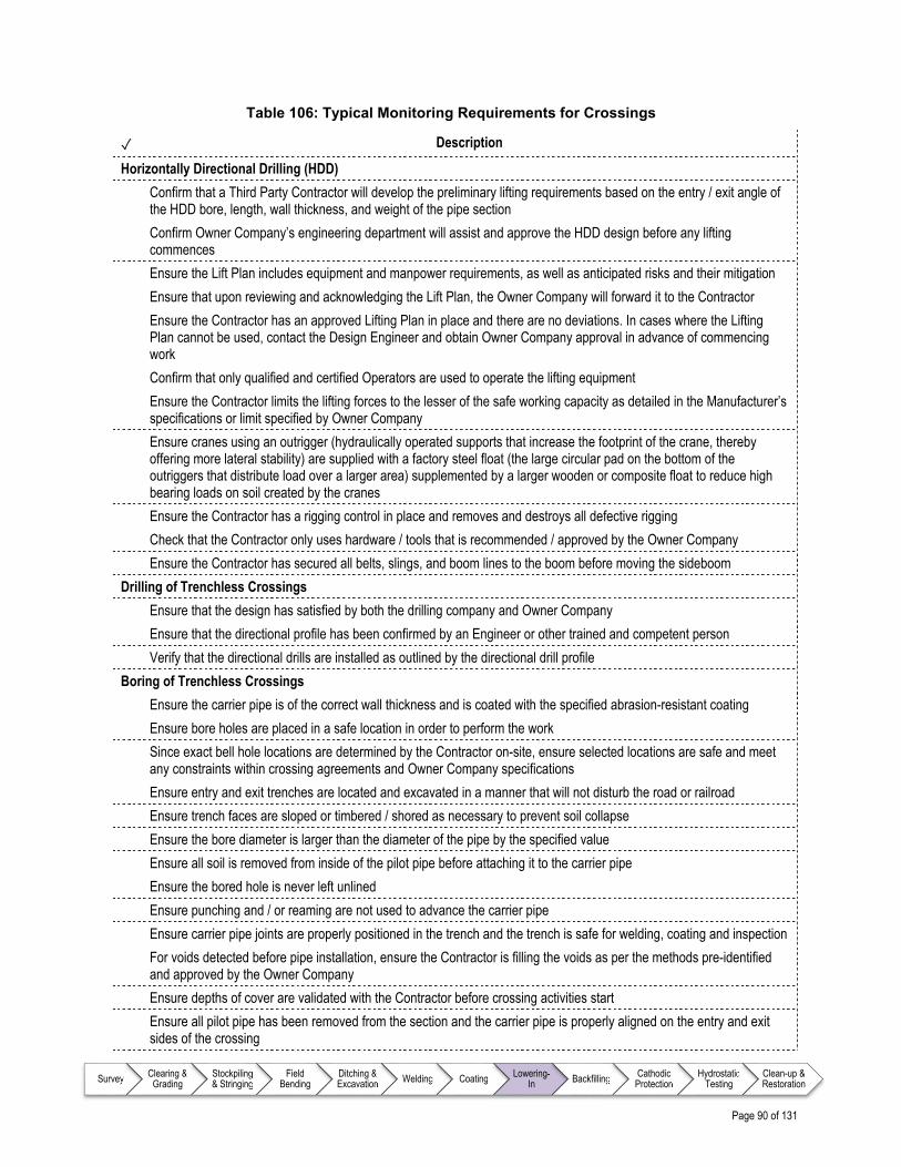
Page 90 of 131
Survey Clearing & Grading
Stockpiling & Stringing
Field Bending
Ditching & Excavation Welding Coating Lowering-
In Backfilling Cathodic Protection
Hydrostatic Testing
Clean-up & Restoration
Table 106: Typical Monitoring Requirements for Crossings
✓ Description
Horizontally Directional Drilling (HDD)
Confirm that a Third Party Contractor will develop the preliminary lifting requirements based on the entry / exit angle of the HDD bore, length, wall thickness, and weight of the pipe section
Confirm Owner Company’s engineering department will assist and approve the HDD design before any lifting commences
Ensure the Lift Plan includes equipment and manpower requirements, as well as anticipated risks and their mitigation
Ensure that upon reviewing and acknowledging the Lift Plan, the Owner Company will forward it to the Contractor
Ensure the Contractor has an approved Lifting Plan in place and there are no deviations. In cases where the Lifting Plan cannot be used, contact the Design Engineer and obtain Owner Company approval in advance of commencing work
Confirm that only qualified and certified Operators are used to operate the lifting equipment
Ensure the Contractor limits the lifting forces to the lesser of the safe working capacity as detailed in the Manufacturer’s specifications or limit specified by Owner Company
Ensure cranes using an outrigger (hydraulically operated supports that increase the footprint of the crane, thereby offering more lateral stability) are supplied with a factory steel float (the large circular pad on the bottom of the outriggers that distribute load over a larger area) supplemented by a larger wooden or composite float to reduce high bearing loads on soil created by the cranes
Ensure the Contractor has a rigging control in place and removes and destroys all defective rigging
Check that the Contractor only uses hardware / tools that is recommended / approved by the Owner Company
Ensure the Contractor has secured all belts, slings, and boom lines to the boom before moving the sideboom
Drilling of Trenchless Crossings
Ensure that the design has satisfied by both the drilling company and Owner Company
Ensure that the directional profile has been confirmed by an Engineer or other trained and competent person
Verify that the directional drills are installed as outlined by the directional drill profile
Boring of Trenchless Crossings
Ensure the carrier pipe is of the correct wall thickness and is coated with the specified abrasion-resistant coating
Ensure bore holes are placed in a safe location in order to perform the work
Since exact bell hole locations are determined by the Contractor on-site, ensure selected locations are safe and meet any constraints within crossing agreements and Owner Company specifications
Ensure entry and exit trenches are located and excavated in a manner that will not disturb the road or railroad
Ensure trench faces are sloped or timbered / shored as necessary to prevent soil collapse
Ensure the bore diameter is larger than the diameter of the pipe by the specified value
Ensure all soil is removed from inside of the pilot pipe before attaching it to the carrier pipe
Ensure the bored hole is never left unlined
Ensure punching and / or reaming are not used to advance the carrier pipe
Ensure carrier pipe joints are properly positioned in the trench and the trench is safe for welding, coating and inspection
For voids detected before pipe installation, ensure the Contractor is filling the voids as per the methods pre-identified and approved by the Owner Company
Ensure depths of cover are validated with the Contractor before crossing activities start
Ensure all pilot pipe has been removed from the section and the carrier pipe is properly aligned on the entry and exit sides of the crossing

Page 91 of 131
Survey Clearing & Grading
Stockpiling & Stringing
Field Bending
Ditching & Excavation Welding Coating Lowering-
In Backfilling Cathodic Protection
Hydrostatic Testing
Clean-up & Restoration
✓ Description
Ensure the direction or angle of the bore has not deviated from the limits of the borehole by looking through one end and seeing at least part of the borehole at the other end
Table 107: Typical Monitoring Requirements for Buoyancy Control
✓ Description
Monitor and record the start and stop locations as well as type of all buoyancy control (e.g., set-on weights, bolt-on weights, continuous concrete)
Monitor and record the spacing between set-on or bolt-on weights Ensure trench depth provides the specified cover to the top of the weight Ensure that lowering-in of a continuous concrete coating section has sideboom support at the specified intervals
defined in the stress analysis Ensure bolt-on weights have wood lagging between weights to avoid movement during installation

Page 92 of 131
Survey Clearing & Grading
Stockpiling & Stringing
Field Bending
Ditching & Excavation Welding Coating Lowering-
In Backfilling Cathodic Protection
Hydrostatic Testing
Clean-up & Restoration
14.7 Typical Outputs for Lowering-In Inspection
Table 108: Typical Reporting Requirements
✓ Description
General
There are no incremental specific reporting requirements beyond those identified in chapter 6.0 Pipeline Construction Inspector – Foundational Information
Daily
Complete lowering-in progress reports, including: Work completed to date, including:
o Coating repairs o Bedding and padding lengths and depths o Field applied rock shield length, and start and end locations o General trench materials/conditions o Buoyancy control types, locations, and start and stop locations o Lowering-in operations carried out per lowering-in specifications, procedures, and drawings
References – Lowering-In
Note to user: The reference information provided in Table 109 is intended as a guide only (i.e., the list is not exhaustive); documents of this nature are updated frequently and it remains the responsibility of the user to ensure that the correct, and most current, documents are referenced as appropriate.
Table 109: List of References – Lowering-In
Document No. Type Title
American Society of Mechanical Engineers (ASME)
ASME B30.05 Standard Mobile Cranes
ASME B30.14 Standard Sideboom Cranes
Canadian Association of Petroleum Producers (CAPP)
CAPP 2004-0022 Guideline Planning Horizontal Directional Drilling for Pipeline Construction
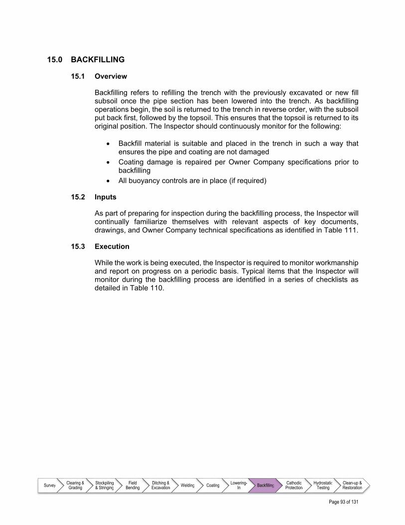
Page 93 of 131
Survey Clearing & Grading
Stockpiling & Stringing
Field Bending
Ditching & Excavation Welding Coating Lowering-
In Backfilling Cathodic Protection
Hydrostatic Testing
Clean-up & Restoration
15.0 BACKFILLING
15.1 Overview
Backfilling refers to refilling the trench with the previously excavated or new fill subsoil once the pipe section has been lowered into the trench. As backfilling operations begin, the soil is returned to the trench in reverse order, with the subsoil put back first, followed by the topsoil. This ensures that the topsoil is returned to its original position. The Inspector should continuously monitor for the following:
Backfill material is suitable and placed in the trench in such a way that ensures the pipe and coating are not damaged
Coating damage is repaired per Owner Company specifications prior to backfilling
All buoyancy controls are in place (if required)
15.2 Inputs
As part of preparing for inspection during the backfilling process, the Inspector will continually familiarize themselves with relevant aspects of key documents, drawings, and Owner Company technical specifications as identified in Table 111.
15.3 Execution
While the work is being executed, the Inspector is required to monitor workmanship and report on progress on a periodic basis. Typical items that the Inspector will monitor during the backfilling process are identified in a series of checklists as detailed in Table 110.

Page 94 of 131
Survey Clearing & Grading
Stockpiling & Stringing
Field Bending
Ditching & Excavation Welding Coating Lowering-
In Backfilling Cathodic Protection
Hydrostatic Testing
Clean-up & Restoration
Table 110: Monitoring Requirements for Backfilling
Item Description Reference
Prior to Commencing Work
On a daily basis, ensure key issues that have been identified are detailed and addressed
Table 112
Safety Monitor the operations for adherence to relevant Owner Company and project specific safety requirements
Table 113
Environmental Considerations
Identifies specific items that should be monitored throughout Backfilling operations that relate specifically to the Owner Company and/or project specific Environmental Protection Plan (EPP)
Table 114
General Operations Identifies overall items that Inspectors should monitor during backfilling operations
Table 115
Materials Padding (e.g., sand) refers to the material placed around the pipe for uniform support and protection against pipe and coating damage; this operation should be monitored for adherence to Owner Company specifications in order to prevent damage to the pipe
Table 116
Pre-Heating Operations (when required)
When the ambient temperature is lower than the installation temperature in specifications and drawings, pre-heating operations will be required before backfilling and monitored for compliance to Owner Company specifications
Table 117
Special Locations Inspectors should monitor for additional items when backfilling at special locations including (but not limited to) open-cut streams, high water table, wetlands, bends, facilities sites, fenced locations and slopes
Table 118
Primary and Secondary Roads – Bored
Primary roads refer to highways and major roads, which are paved main roads with large traffic volumes, well-marked traffic lanes, shoulders, and ditches
Secondary roads refer to roads with moderate traffic volumes, well-marked traffic lanes and with / without shoulders or ditches. These roads are surfaced with granular materials, soil or both. These roads also include private driveways, roadways, access roads, etc.
Inspectors will monitor for additional requirements for bored road crossings
Table 119
Open-Cut Roads In special cases where approval has been obtained for a pipeline to be installed by cutting the road open, inspect and ensure that the Contractor is abiding additional requirements by the Owner Company
Table 120
Horizontal Directional Drilling (HDD)
For horizontal directionally bored crossings, Inspectors will monitor Contractor activities for additional items
Table 121
15.4 Outputs
The Inspector is required to report on workmanship and progress on a periodic basis (e.g., daily or weekly) by completing various reports on each work day and end of week. Report requirements and reporting processes are Owner Company and project specific; however, best practices for reporting requirements for backfilling appear in Table 122.

Page 95 of 131
Survey Clearing & Grading
Stockpiling & Stringing
Field Bending
Ditching & Excavation Welding Coating Lowering-
In Backfilling Cathodic Protection
Hydrostatic Testing
Clean-up & Restoration
Detailed Checklists – Backfilling
15.5 Typical Inputs for Backfilling Inspection
Table 111: Information Requirements for Backfilling
✓ Description
All designs, drawings, and specifications developed by the Owner Company and Contractors related to backfilling, such as: Access Road Drawings Line List (e.g., special concerns for each Land Owner) Backfill Specifications
Contracts and agreements related to: Road Use Crossing for Buried Facilities Construction Survey
Permits related to: Environmental Road Use
Owner Company specific Safety Plan, including (but not limited to): Traffic Control Plan Requirements for Personal Protective Equipment (PPE) Procedures for working around overhead powerlines Emergency Medical Services (EMS)
Project specific Environmental Protection Plan (EPP) detailing backfilling requirements for the following (but not limited to): Watercourses Wetlands, muskeg, and swamp areas Wildlife habitats Migratory routes
Other project specific Plans, which may include: Refer to project documentation for incremental specific requirements
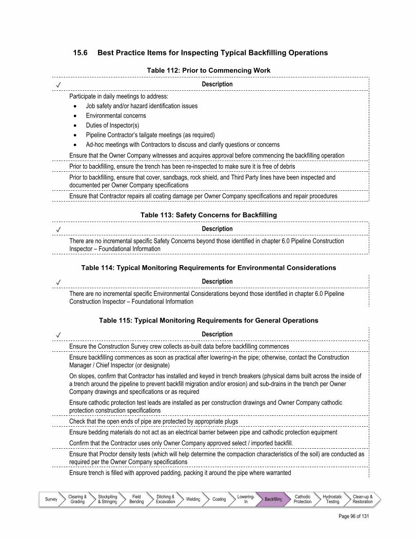
Page 96 of 131
Survey Clearing & Grading
Stockpiling & Stringing
Field Bending
Ditching & Excavation Welding Coating Lowering-
In Backfilling Cathodic Protection
Hydrostatic Testing
Clean-up & Restoration
15.6 Best Practice Items for Inspecting Typical Backfilling Operations
Table 112: Prior to Commencing Work
✓ Description
Participate in daily meetings to address: Job safety and/or hazard identification issues Environmental concerns Duties of Inspector(s) Pipeline Contractor’s tailgate meetings (as required) Ad-hoc meetings with Contractors to discuss and clarify questions or concerns
Ensure that the Owner Company witnesses and acquires approval before commencing the backfilling operation
Prior to backfilling, ensure the trench has been re-inspected to make sure it is free of debris
Prior to backfilling, ensure that cover, sandbags, rock shield, and Third Party lines have been inspected and documented per Owner Company specifications
Ensure that Contractor repairs all coating damage per Owner Company specifications and repair procedures
Table 113: Safety Concerns for Backfilling
✓ Description
There are no incremental specific Safety Concerns beyond those identified in chapter 6.0 Pipeline Construction Inspector – Foundational Information
Table 114: Typical Monitoring Requirements for Environmental Considerations
✓ Description
There are no incremental specific Environmental Considerations beyond those identified in chapter 6.0 Pipeline Construction Inspector – Foundational Information
Table 115: Typical Monitoring Requirements for General Operations
✓ Description
Ensure the Construction Survey crew collects as-built data before backfilling commences
Ensure backfilling commences as soon as practical after lowering-in the pipe; otherwise, contact the Construction Manager / Chief Inspector (or designate)
On slopes, confirm that Contractor has installed and keyed in trench breakers (physical dams built across the inside of a trench around the pipeline to prevent backfill migration and/or erosion) and sub-drains in the trench per Owner Company drawings and specifications or as required
Ensure cathodic protection test leads are installed as per construction drawings and Owner Company cathodic protection construction specifications
Check that the open ends of pipe are protected by appropriate plugs
Ensure bedding materials do not act as an electrical barrier between pipe and cathodic protection equipment
Confirm that the Contractor uses only Owner Company approved select / imported backfill.
Ensure that Proctor density tests (which will help determine the compaction characteristics of the soil) are conducted as required per the Owner Company specifications
Ensure trench is filled with approved padding, packing it around the pipe where warranted

Page 97 of 131
Survey Clearing & Grading
Stockpiling & Stringing
Field Bending
Ditching & Excavation Welding Coating Lowering-
In Backfilling Cathodic Protection
Hydrostatic Testing
Clean-up & Restoration
✓ Description
Ensure trench is filled with excavated material to provide firm support for the pipe Ensure padding or select backfill is used to provide a minimum cushion between the top of the pipe and the start of
rocky backfill, as specifications and drawings stipulate and Contractor does not place rocky backfill directly on the lowered pipe
Ensure rock shield or wood lagging is used through areas of coarse gravel and small cobble stone, instead of support bags or pillows and padding (if warranted)
Ensure larger rocks with sizes too large for backfill are hauled away or stacked neatly along the ROW as specified in Owner Company specifications and drawings
Check that marker tape is installed in the ditch above the pipe, where required by Owner Company
Continuously monitor that pipes sharing a common ditch maintain the minimum distance as specified in the design documents
Continuously monitor that soil is backfilled in the same sequence, or in the same geotechnical layers, as when it was removed during trenching operations
Confirm that the spoil will be placed directly on top of the pipeline with an auger type (a tool with a horizontal helical bit that physically moves backfill off the ROW surface directly into the trench) backfill technique wherever possible; otherwise, confirm that an excavator (back hoe or track hoe) will initially place spoil before a bulldozer is used for backfill
Ensure there is minimum cover over the installed pipe (or top of concrete weights) as specified in Owner Company or project specifications
Ensure final backfilled surface is level across the trench
Ensure soil compacting of agricultural (cultivated, pasture, and native range) land is carried out if specified in Owner Company or project specifications, drawings, and line lists
Ensure that overall drainage control measures are undertaken as advised by the line list
Check that watercourses or land drain reinstatement are correct and are functioning properly
Check that ditch plugs and sack breakers are installed at the locations defined by the terrain and project specifications
Continually observe for sinkholes along the ditch line and stop work for consultation with the Construction Manager / Chief Inspector (or designate) when identified or suspected
Ensure that the Contractor compacts the spoil in the trench so that the trench crown (berm) is no higher than specified by Owner Company
Confirm that the top-most specified depth of the backfilled trench and crown for cultivated land are rock-free
Ensure that Contractor leaves openings in the trench crown (berm) as required to allow for natural drainage of surface water
Ensure that the right of way (ROW) is left in as close to original condition as possible
Confirm that the Contractor will conduct final clean-up when soils are dry and unfrozen. Final clean-up should be delayed until spring when spoil can be adequately compacted in the trench and spoil and topsoil can be removed from the sod surface more accurately
Confirm that the Contractor removes spoil and stored topsoil to eliminate scalping of native sod, in a manner approved by the Owner Company
Confirm that the Contractor replaces soils with adverse chemical properties within the area from which they were removed, to eliminate spread outside of the excavated site
Confirm that the Contractor re-contours graded portions of the ROW to match the surrounding landforms and drainage patterns
Confirm that the Contractor provides adequate erosion protection (installing suitable geotextiles) where surface drainage crosses the trench line and to prevent surface drainage from flowing down trench line

Page 98 of 131
Survey Clearing & Grading
Stockpiling & Stringing
Field Bending
Ditching & Excavation Welding Coating Lowering-
In Backfilling Cathodic Protection
Hydrostatic Testing
Clean-up & Restoration
✓ Description
Confirm that the Contractor re-distributes salvaged topsoil carefully over the stripped area (e.g., the size and type of equipment used and the number of passes that are needed to replace topsoil is key to reclamation success as overworking some soils can result in increased pulverization, loss of organic matter, and increased erosion potential)
Confirm that Contractor picks surface rock to match the stoniness level of the surrounding landscape If required, ensure that the Contractor uses track hoes equipped with clean-up buckets to shade the pipe berm (per
initial backfill procedure) and replaces the bulk of the spoil
Winter Construction
Confirm that during winter construction trench excavation, pipe lowering-in and backfilling is completed by the Contractor within 24 hours or as agreed with the Owner Company
Ensure solidified or frozen backfill is broken up with a screw auger, power dozer, or other approved equipment
Ensure that any snow or ice is removed from the compacted layer prior to placement of subsequent layers
Ensure that during winter construction, the Contractor leaves a trench crown (berm) over the trench to compensate for settlement upon thawing of frozen soils as indicated in Owner Company specifications, construction drawings, and agreements
Table 116: Typical Monitoring Requirements for Materials
✓ Description
Ensure that top soil is never used as padding material or fill Ensure that the back fill material is soft, free from large rocks, stumps, frozen material, or any other foreign material that
can dent the pipe or scratch the external coating as per Owner Company specifications Ensure that when excavated material is not suitable for backfill, Owner Company approved imported material is used
for padding above and below the pipe Ensure that when gravel or gravel / sand mixture is used as backfilling material for buoyancy control purposes where
trench walls provide firm support, the material is free-draining and exhibits sufficient shear strength when thawed and mixed with water
Confirm that earth filled sacks or rock riprap (rock or other support material used to armor drainage ditches and trench walls) are used for erosion control
Sand Padding Confirm that if the excavated material is not suitable for padding, either a mechanical separator will be brought in or
approved padding material will be hauled in and placed around the pipeline Ensure that where sand is used for padding, it is dry, unfrozen, and free from any rocks larger than specification or
having sharp edges Ensure Contractor applies sand padding after sandbags and foam support pillows are placed in the trench Ensure Contractor uses only sandbags or foam pillows to support the pipe Ensure Contractor places the minimum thickness specified of sand-padding on top of the lowered pipe as indicated in
Owner Company or project specifications, construction drawings, and agreements Confirm that Contractor is using auger equipment for backfill where coarse fragments are encountered in trench
materials

Page 99 of 131
Survey Clearing & Grading
Stockpiling & Stringing
Field Bending
Ditching & Excavation Welding Coating Lowering-
In Backfilling Cathodic Protection
Hydrostatic Testing
Clean-up & Restoration
Table 117: Typical Monitoring Requirements for Pre-Heating Operations (if required)
✓ Description
Ensure pipeline is preheated by blowing hot air through the pipeline
Ensure temperatures at the inlet and outlet of the pipeline are being constantly monitored
Ensure inlet temperature does not exceed the pipe coating design temperature
Ensure outlet temperature is never less than the specified installation temperature
Ensure backfilling and compaction is completed while pipeline temperature is maintained above specified installation temperature
Ensure the length of pre-heated section is as per Owner Company specifications
Ensure all wet areas on the right of way (ROW) are red lined for future reference
Table 118: Typical Monitoring Requirements for Special Locations
✓ Description
Confirm that gravel and/or sand filled bags are used on solidly compacted backfill at open-cut water crossings that may be subject to erosion
Confirm that concrete weights or backfilling are used as specified in Owner Company or project specifications to overcome the upward buoyancy force on the pipe due to a high water table or use sand bags in wetlands
Ensure that for bends where no foam boxes are specified by engineering design, a minimum of sand padding will be provided based on specifications. The padding should extend beyond the tangent on both sides of the bend
Ensure the Contractor is backfilling and finishing the grade at compressor and pump stations, mainline valves, temporary tie-overs, meter stations and other sites with fenced enclosures, as per Owner Company specifications
Ensure that cathodic protection test leads remain intact and accessible above ground
Table 119: Typical Monitoring Requirements for Primary and Secondary Roads – Bored
✓ Description
Ensure Contractor supports both ends of the bored crossing according to project specifications, construction drawings, and agreements
Ensure Contractor backfills excavated trench outside the road edges with granular materials according to Owner Company specifications, construction drawings, and agreements
Ensure Contractor backfills and compacts outside the bore edges, below the pipe, and/or places sandbags below the pipe to minimize the risk of pipe settlement and potential buckling
Table 120: Typical Monitoring Requirements for Open-Cut Roads
✓ Description
Confirm that for secondary roads, the Contractor uses excavated trench materials up to a specified distance below the road surface if material is free of moisture and rocks. Remaining backfill will be with select, imported, granular materials according to project specifications, construction drawings, and agreements
Ensure that backfilling is accomplished in layers, with each layer thoroughly compacted to the specified requirements with Owner Company approved vibration type tamping machines to produce a smooth and even surface
Ensure that for repaving road surfaces, the Contractor cleans the adjacent roadway outside the open-cut trench and shoulders of all mud and debris, then pave the road to leave a smooth and even surface
Confirm that the final topping is of granular material to match with existing road surface
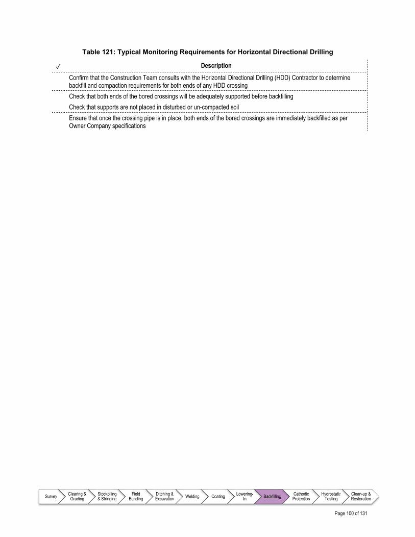
Page 100 of 131
Survey Clearing & Grading
Stockpiling & Stringing
Field Bending
Ditching & Excavation Welding Coating Lowering-
In Backfilling Cathodic Protection
Hydrostatic Testing
Clean-up & Restoration
Table 121: Typical Monitoring Requirements for Horizontal Directional Drilling
✓ Description
Confirm that the Construction Team consults with the Horizontal Directional Drilling (HDD) Contractor to determine backfill and compaction requirements for both ends of any HDD crossing
Check that both ends of the bored crossings will be adequately supported before backfilling
Check that supports are not placed in disturbed or un-compacted soil
Ensure that once the crossing pipe is in place, both ends of the bored crossings are immediately backfilled as per Owner Company specifications
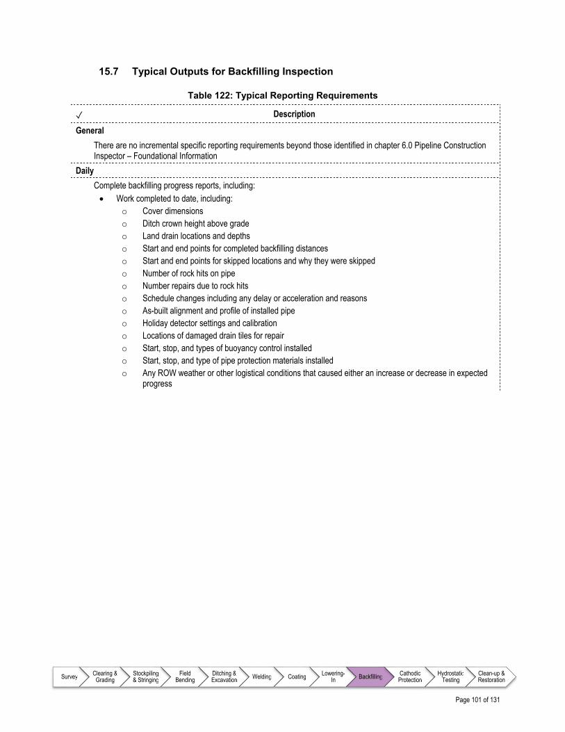
Page 101 of 131
Survey Clearing & Grading
Stockpiling & Stringing
Field Bending
Ditching & Excavation Welding Coating Lowering-
In Backfilling Cathodic Protection
Hydrostatic Testing
Clean-up & Restoration
15.7 Typical Outputs for Backfilling Inspection
Table 122: Typical Reporting Requirements
✓ Description
General
There are no incremental specific reporting requirements beyond those identified in chapter 6.0 Pipeline Construction Inspector – Foundational Information
Daily
Complete backfilling progress reports, including: Work completed to date, including:
o Cover dimensions o Ditch crown height above grade o Land drain locations and depths o Start and end points for completed backfilling distances o Start and end points for skipped locations and why they were skipped o Number of rock hits on pipe o Number repairs due to rock hits o Schedule changes including any delay or acceleration and reasons o As-built alignment and profile of installed pipe o Holiday detector settings and calibration o Locations of damaged drain tiles for repair o Start, stop, and types of buoyancy control installed o Start, stop, and type of pipe protection materials installed o Any ROW weather or other logistical conditions that caused either an increase or decrease in expected
progress

Page 102 of 131
Survey Clearing & Grading
Stockpiling & Stringing
Field Bending
Ditching & Excavation Welding Coating Lowering-
In Backfilling Cathodic Protection
Hydrostatic Testing
Clean-up & Restoration
References – Backfilling
Note to user: The reference information provided in Table 123 is intended as a guide only (i.e., the list is not exhaustive); documents of this nature are updated frequently and it remains the responsibility of the user to ensure that the correct, and most current, documents are referenced as appropriate.
Table 123: List of References – Backfilling
Document No. Type Title
There are no incremental specific reference documents beyond those identified in chapter 6.0 Pipeline Construction Inspector – Foundational Information

Page 103 of 131
Survey Clearing & Grading
Stockpiling & Stringing
Field Bending
Ditching & Excavation Welding Coating Lowering-
In Backfilling Cathodic Protection
Hydrostatic Testing
Clean-up & Restoration
16.0 CATHODIC PROTECTION
16.1 Overview
Cathodic protection (CP) is a technique used to control corrosion of a pipeline’s metal surface by making the pipeline the cathode of an electrochemical cell. In other words, CP is a simple method of protection where the pipeline is connected to a more easily corroded (sacrificial) metal (e.g., magnesium) which acts as the anode. The sacrificial metal then corrodes instead of the pipeline. However, for long pipelines, this passive galvanic cathodic protection is not adequate, and an external direct current (DC) electrical power source (rectifier) can be used to provide additional electrical current to protect the pipe. As part of the CP system, test stations are required to take readings on a periodic basis. Typically, these test stations are installed at intervals of two to three kilometers (1.2 – 1.9 miles), not to exceed five kilometers (3.1 miles). Cathodic test leads, sacrificial anodes, negative drain leads, and ground bed cables are some of the major components that are installed at these stations to complete a cathodic protection system. The Inspector's concern should be directed not only toward new installations but to existing Third Party buried facilities and their cathodic protection systems where there is potential for damage during excavation.
16.2 Inputs
As part of preparing for inspection during the cathodic protection process, the Inspector will continually familiarize themselves with relevant aspects of key documents, drawings, and Owner Company technical specifications as identified in Table 125.
16.3 Execution
While the work is being executed, the Inspector is required to monitor workmanship and report on progress on a periodic basis. Typical items that the Inspector will monitor for during the cathodic protection process are identified in a series of checklists as detailed in Table 124.

Page 104 of 131
Survey Clearing & Grading
Stockpiling & Stringing
Field Bending
Ditching & Excavation Welding Coating Lowering-
In Backfilling Cathodic Protection
Hydrostatic Testing
Clean-up & Restoration
Table 124: Monitoring Requirements for Cathodic Protection
Item Description Reference
Prior to Commencing Work
On a daily basis, ensure key issues that have been identified are detailed and addressed
Table 126
Safety Monitor the operations for adherence to relevant Owner Company and project specific safety requirements
Table 127
Environmental Considerations
Identifies specific items that should be monitored throughout Cathodic Protection operations that relate specifically to the Owner Company and/or project specific Environmental Protection Plan (EPP)
Table 128
CP Installation Monitor the installation of cathodic protection systems for safety as well as adherence to Owner Company specifications. In particular, incorporate considerations for locating cathodic protection test stations such as: o Ease of accessibility of proposed installation location (e.g., on
existing fence lines) o Use of existing facilities (e.g., valve or scraper trap locations) o Land Owner restrictions
Table 129
CP at Third Party Pipeline Crossings
Ensure sufficient communication with Third Party Pipeline Owners to facilitate that requirements of the crossing agreement are met in a safe and efficient manner
Table 130
16.4 Outputs
The Inspector is required to report on workmanship and progress on a periodic basis (e.g., daily or weekly) by completing various reports on each work day and end of week. Report requirements and reporting processes are Owner Company and project specific; however, best practices for reporting requirements for cathodic protection appear in Table 131.

Page 105 of 131
Survey Clearing & Grading
Stockpiling & Stringing
Field Bending
Ditching & Excavation Welding Coating Lowering-
In Backfilling Cathodic Protection
Hydrostatic Testing
Clean-up & Restoration
Detailed Checklists – Cathodic Protection
16.5 Typical Input Requirements for Cathodic Protection Inspection
Table 125: Information Requirements for Cathodic Protection
✓ Description
All designs, drawings, and specifications developed by the Owner Company and Contractors related to cathodic protection, such as: Access Road Drawings Line List (e.g., special concerns for each Land Owner) Cathodic Protection Installation Specifications Cathodic Protection Testing Specifications Third Party utility locations where CP connections are required Locations and Types of Ground Beds and Anodes
Contracts and agreements related to: Road Use Crossing for Buried Facilities Crossing Agreements Cathodic Protection Installation Construction Survey
Permits related to: Environmental Road Use
Owner Company specific Safety Plan, including (but not limited to): Traffic Control Plan Requirements for Personal Protective Equipment (PPE) Emergency Medical Services (EMS)
Project specific Environmental Protection Plan (EPP) detailing cathodic protection requirements
Other project specific Plans, which may include: Cathodic Protection and Installation Fire Prevention / Firefighting Plan

Page 106 of 131
Survey Clearing & Grading
Stockpiling & Stringing
Field Bending
Ditching & Excavation Welding Coating Lowering-
In Backfilling Cathodic Protection
Hydrostatic Testing
Clean-up & Restoration
16.6 Best Practice Items for Inspecting Typical Cathodic Protection Operations
Table 126: Prior to Commencing Work
✓ Description
Participate in daily meetings to address: Cathodic protection requirements as per Owner Company specifications Job safety and/or hazard identification issues Environmental concerns Duties of Inspector(s) Pipeline Contractor’s tailgate meetings (as required) Ad-hoc meetings with Contractors to discuss and clarify questions or concerns
Table 127: Safety Concerns for Cathodic Protection
✓ Description
Confirm that Manufacturer’s instructions are followed in the use of thermite devices
Table 128: Typical Monitoring Requirements for Environmental Considerations
✓ Description
There are no incremental specific Environmental Considerations beyond those identified in chapter 6.0 Pipeline Construction Inspector – Foundational Information
Table 129: Typical Monitoring Requirements for Cathodic Protection Installation
✓ Description
If possible, ensure installation of cathodic test stations near existing roads for ease of accessibility during subsequent periodic testing in locations specified on project drawings
Confirm if existing rectifiers are to be shut down in areas where existing pipe maintenance programs are under way Ensure test leads are backfilled carefully to avoid breaking wire-to-pipe connections and to avoid burying the lead wires
before connections to the junction boxes are completed Confirm that both ends of the conduit leading up to the junction box are reamed out to remove any burrs that may
cause a short in test lead wires Ensure test leads are tested electrically after backfill to confirm that wire-to-pipe connections have not been broken Confirm that test lead conduits are installed at locations and in a manner per the Owner Company specification (e.g.,
typically to the right of the centerline of pipe when facing downstream in the direction of gas flow)

Page 107 of 131
Survey Clearing & Grading
Stockpiling & Stringing
Field Bending
Ditching & Excavation Welding Coating Lowering-
In Backfilling Cathodic Protection
Hydrostatic Testing
Clean-up & Restoration
Table 130: Typical Monitoring Requirements for Cathodic Protection at Third Party Pipeline Crossings
✓ Description
Ensure the Third Party pipeline company is notified prior to any work on or near their pipeline. Typically, a representative from the Third Party pipeline company is present to observe or they themselves conduct the work
Ensure that work undertaken in the vicinity of a Third Party Pipeline Company’s cathodic protection system adheres to requirements identified for crossings in Third Party Owner Company and Owner Company specifications
Confirm that existing ground cables connected to Third Party buried facilities are disconnected and moved out of harm’s way during construction; however, ensure that any alternating current (A/C) interference mitigation concerns are addressed
After daylighting the Third Party pipeline, ensure coating is examined to determine type, condition, and possible damage; notify the Third Party Pipeline Owner if damage is found
At the Third Party pipeline crossing, ensure CP readings are taken by: Using existing test leads on the Third Party pipeline Take a pipe-to-soil reading if the coating has been damaged Take a reading at the nearest Third Party pipeline’s test station
Ensure the Third Party pipeline coating is never punctured to take a pipe-to-soil reading
Ensure if a test lead is to be attached to the Third Party pipeline, a Third Party Pipeline Company Representative will be present to perform the work themselves, unless otherwise agreed upon
Confirm that at Third Party pipeline crossings, test leads are installed at all line crossings
Confirm that test stations are installed as close to pipeline crossings as possible

Page 108 of 131
Survey Clearing & Grading
Stockpiling & Stringing
Field Bending
Ditching & Excavation Welding Coating Lowering-
In Backfilling Cathodic Protection
Hydrostatic Testing
Clean-up & Restoration
16.7 Typical Outputs for Cathodic Protection Inspection
Table 131: Typical Reporting Requirements
✓ Description
General
Complete cathodic protection (CP) installation / test station report, including: Number of Test Station Installations Test Station Survey Numbers Continuity Test Results (i.e., upon backfilling to ensure test leads have not broken)
Complete Third Party pipeline crossing report, including: Survey Station Numbers at Crossings Name of Third Party Pipeline Companies Pipeline Size and Use Type and Condition of Coating Clearance Above or Below Pipeline Distance from Nearest Third Party Rectifier Output from Third Party Rectifier Pipe to Soil Readings at Crossing If test leads are installed, Size and Color of Wire Description of Location; Township, Range, Section, and Land Owner (tract number from alignment sheet) Sketch of the Pipeline Crossing Showing Available Landmarks
Daily
There are no incremental specific reporting requirements beyond those identified in chapter 6.0 Pipeline Construction Inspector – Foundational Information

Page 109 of 131
Survey Clearing & Grading
Stockpiling & Stringing
Field Bending
Ditching & Excavation Welding Coating Lowering-
In Backfilling Cathodic Protection
Hydrostatic Testing
Clean-up & Restoration
References – Cathodic Protection
Note to user: The reference information provided in Table 132 is intended as a guide only (i.e., the list is not exhaustive); documents of this nature are updated frequently and it remains the responsibility of the user to ensure that the correct, and most current, documents are referenced as appropriate.
Table 132: List of References – Cathodic Protection
Document No. Type Title
Canadian Gas Association (CGA)
OCC-1 Standard Recommended Practices for Control of External Corrosion on Buried or Submerged Metallic Piping Systems
NACE International
SP0169 Standard Standard Practice for Control of External Corrosion on Underground or Submerged Metallic Piping Systems
SP0177 Standard Standard Practice for Mitigation of Alternating Current and Lightning Effects on Metallic Structures and Corrosion Control Systems
SP0188 Standard Standard Practice for Discontinuity (Holiday) Testing of New Protective Coatings on Conductive Substrates

Page 110 of 131
Survey Clearing & Grading
Stockpiling & Stringing
Field Bending
Ditching & Excavation Welding Coating Lowering-
In Backfilling Cathodic Protection
Hydrostatic Testing
Clean-up & Restoration

Page 111 of 131
Survey Clearing & Grading
Stockpiling & Stringing
Field Bending
Ditching & Excavation Welding Coating Lowering-
In Backfilling Cathodic Protection
Hydrostatic Testing
Clean-up & Restoration
17.0 HYDROSTATIC TESTING
17.1 Overview
A hydrostatic test is a form of pressure testing used to confirm that the pipeline has acceptable strength and will not leak under operating conditions. Hydrostatic testing uses water (as opposed to air) to perform the test. Owner Companies pressure test a new pipeline after it is installed but before it is put into service for the following reasons:
Prove the integrity of the fabricated assemblies, including all welds, to ensure the safety of the public, environment, and surrounding property
Confirm the quality of fabricated assemblies, line pipe materials supplied by Vendors, and field welds performed on the ROW to ensure the pipeline system can safely operate within the specified maximum operating pressure (MOP)
Prove the workmanship of Fabricators
Comply with industry and governing body regulations Caution: Air contains significantly more stored energy compared to water and poses increased risk during the test; as a result, it is only used for pressure testing under situations where the elevation differences result in an impractical number of test sections or if there is a shortage of water. For this reason, the scope of this document is limited to hydrostatic testing.
17.2 Inputs
As part of preparing for inspection during the hydrostatic testing process, the Inspector will continually familiarize themselves with relevant aspects of key documents, drawings, and Owner Company technical specifications as identified in Table 134.
17.3 Execution
While the work is being executed, the Inspector is required to monitor workmanship and report on progress on a periodic basis. Typical items that the Inspector will monitor for during the hydrostatic testing process are identified in a series of checklists, organized around the typical sequence of events during hydrostatic testing, as detailed in Table 133.

Page 112 of 131
Survey Clearing & Grading
Stockpiling & Stringing
Field Bending
Ditching & Excavation Welding Coating Lowering-
In Backfilling Cathodic Protection
Hydrostatic Testing
Clean-up & Restoration
Table 133: Monitoring Requirements for Hydrostatic Testing
Item Description Reference
Prior to Commencing Work On a daily basis, ensure key issues that have been identified are detailed and addressed
Review and confirm all testing equipment has been certified as fully functional in advance of the testing operations
Table 135
Safety Monitor the operations for adherence to relevant Owner Company and project specific safety requirements
Table 136
Environmental Considerations Identifies specific items that should be monitored throughout Hydrostatic Testing operations that relate specifically to the Owner Company and/or project specific Environmental Protection Plan (EPP)
Table 137
Preparing Test Sections Monitor Contractor work to ensure that the test section is prepared (e.g., installation of test heads, cleaning, test water removal, and equipment use) to Owner Company specifications
Table 138
Preparing for Pressure Test Ensure all required permits, plans, and calculations are approved and in place prior to commencing hydrostatic test operation
Table 139
Filling the Pipe Confirm pipe is filled as per Hydrostatic Test Plan Table 140
Preparing for Pressurization Ensure all instrumentation and equipment is in place prior to pressuring the test section, including setting up a “Test Bus”
Table 141
Pressurization Establishing Pressure-Volume Curve
Determine slope of pressure-volume curve (the relationship between the volume of water injected into the test section and the corresponding pressure rise)
Table 142
Leak Check (if required)
If there is need for a yield plot, then while the fill pump is shut off, the test heads should be checked for leaks and pressures compared at two test head pressure gauges and validated against elevation differences
Table 143
Strength Test
Proof of strength of installed pipe as per Hydrostatic Test Plan Table 144
Leak Test Follow controlled depressurization process from strength test to leak test
Table 145
Leak or Failure Investigation (if required)
In the case of a pipe leak or failure during hydrostatic testing, the Contractor will visually inspect the test section route for water ponding or wet soils, locate the leak or determine the cause of the failure, and advise the Inspector. If visual inspection does not reveal the leak location, advise the Owner Company of further action
The Inspector will notify the Construction Manager / Chief Inspector (or designate) and work with the Contractor to develop a Leak Detection Plan and have it approved. When a leak is discovered, the Contractor will repair the pipe section and the hydrostatic test will be conducted again
Table 146
Depressurizing Ensure depressurizing happens safely in preparation for dewatering and drying
Table 147
Dewatering Confirm dewatering happens in a manner consistent with environmental permits and approvals
Table 148
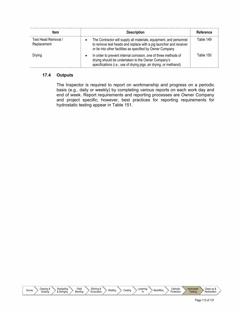
Page 113 of 131
Survey Clearing & Grading
Stockpiling & Stringing
Field Bending
Ditching & Excavation Welding Coating Lowering-
In Backfilling Cathodic Protection
Hydrostatic Testing
Clean-up & Restoration
Item Description Reference
Test Head Removal / Replacement
The Contractor will supply all materials, equipment, and personnel to remove test heads and replace with a pig launcher and receiver or tie into other facilities as specified by Owner Company
Table 149
Drying In order to prevent internal corrosion, one of three methods of drying should be undertaken to the Owner Company’s specifications (i.e., use of drying pigs, air drying, or methanol)
Table 150
17.4 Outputs
The Inspector is required to report on workmanship and progress on a periodic basis (e.g., daily or weekly) by completing various reports on each work day and end of week. Report requirements and reporting processes are Owner Company and project specific; however, best practices for reporting requirements for hydrostatic testing appear in Table 151.

Page 114 of 131
Survey Clearing & Grading
Stockpiling & Stringing
Field Bending
Ditching & Excavation Welding Coating Lowering-
In Backfilling Cathodic Protection
Hydrostatic Testing
Clean-up & Restoration
Detailed Checklists – Hydrostatic Testing
17.5 Typical Input Requirements for Hydrostatic Testing Inspection
Table 134: Information Requirements for Hydrostatic Testing
✓ Description
All designs, drawings, and specifications developed by the Owner Company and Contractors related to hydrostatic testing, such as: Alignment Sheets Pipeline Facility Drawings Line List (e.g., special concerns for each Land Owner) Drawings specific to hydrostatic test (including but not limited to):
o Temporary Launchers and Receivers o Elevation Profiles
Contracts and agreements related to: Road Use Crossing for Buried Facilities Construction Survey
Permits related to: Road Use Water Withdrawal and Discharge for Hydrostatic Test
Owner Company specific Safety Plan, including (but not limited to): Traffic Control Plan Requirements for Personal Protective Equipment (PPE) Emergency Medical Services (EMS) Emergency Contact List
Project specific Environmental Protection Plan (EPP) detailing hydrostatic testing requirements
Other project specific Plans, which may include: Hydrostatic Test Plan addressing (but not limited to) the following items:
o Site specific safety / hazards and appropriate analysis o Emergency Response Plan in the event of a rupture during the test o Testing personnel emergency contact list o Test section design process o Determination of class locations o Elevation profiles o Test section lengths o Test water sourcing, filling, pressurizing, depressurizing, and dewatering o Accessibility to test sections o Road crossings and signage o Possible reduction of the number of sections with heavy wall pipe o The sequencing of hydrostatic tests o Test pressure calculations o Minimum test head rating o Testing crew credentials o Test equipment list and capacities
Page 115 of 131
Survey Clearing & Grading
Stockpiling & Stringing
Field Bending
Ditching & Excavation Welding Coating Lowering-
In Backfilling Cathodic Protection
Hydrostatic Testing
Clean-up & Restoration
✓ Description
o Test schedule and sequence of tests o Instrumentation and their certification o Provision of protective berms around fuel storage used to supply fuel-driven line fill pumps (as required) o Leak Detection Mechanism / Plan (if required)
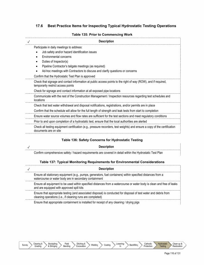
Page 116 of 131
Survey Clearing & Grading
Stockpiling & Stringing
Field Bending
Ditching & Excavation Welding Coating Lowering-
In Backfilling Cathodic Protection
Hydrostatic Testing
Clean-up & Restoration
17.6 Best Practice Items for Inspecting Typical Hydrostatic Testing Operations
Table 135: Prior to Commencing Work
✓ Description
Participate in daily meetings to address: Job safety and/or hazard identification issues Environmental concerns Duties of Inspector(s) Pipeline Contractor’s tailgate meetings (as required) Ad-hoc meetings with Contractors to discuss and clarify questions or concerns
Confirm that the Hydrostatic Test Plan is approved
Check that signage and contact information at public access points to the right of way (ROW), and if required, temporarily restrict access points
Check for signage and contact information at all exposed pipe locations
Communicate with the rest of the Construction Management / Inspection resources regarding test schedules and locations
Check that test water withdrawal and disposal notifications, registrations, and/or permits are in place
Confirm that the schedule will allow for the full length of strength and leak tests from start to completion
Ensure water source volumes and flow rates are sufficient for the test sections and meet regulatory conditions
Prior to and upon completion of a hydrostatic test, ensure that the local authorities are alerted
Check all testing equipment certification (e.g., pressure recorders, test weights) and ensure a copy of the certification documents are on site
Table 136: Safety Concerns for Hydrostatic Testing
✓ Description
Confirm comprehensive safety / hazard requirements are covered in detail within the Hydrostatic Test Plan
Table 137: Typical Monitoring Requirements for Environmental Considerations
✓ Description
Ensure all stationary equipment (e.g., pumps, generators, fuel containers) within specified distances from a watercourse or water body are in secondary containment
Ensure all equipment to be used within specified distances from a watercourse or water body is clean and free of leaks and are equipped with approved spill kits
Ensure that appropriate testing (and associated disposal) is conducted for disposal of test water and debris from cleaning operations (i.e., if cleaning runs are completed)
Ensure that appropriate containment is installed for receipt of any cleaning / drying pigs

Page 117 of 131
Survey Clearing & Grading
Stockpiling & Stringing
Field Bending
Ditching & Excavation Welding Coating Lowering-
In Backfilling Cathodic Protection
Hydrostatic Testing
Clean-up & Restoration
Table 138: Typical Monitoring Requirements for Preparing Test Sections
✓ Description
Check that the lengths of exposed pipe (at the ends where test heads are connected) are kept to a minimum Ensure that any required bell holes (small excavated areas) are monitored for air quality Ensure that during winter construction, hoarding (plastic insulation over a wood frame used to maintain temperature
around an exposed section of pipe) and heating is installed for exposed test section ends where test heads are to be welded
Inspect the test heads and isolation values and ensure that they are refurbished as required Ensure that the test heads are welded per Owner Company specifications; ensure that specialized welding inspection
expertise is engaged for welding process (as per Section 12.0) Ensure good access to isolation valves (either through orientation of installation and/or scaffolding) Ensure that safety zones around test heads / pigging launchers and receivers are established and maintained
throughout the operation Confirm that the Environmental Inspector is collecting and sending fill water for laboratory testing so that results are
available before filling
Table 139: Typical Monitoring Requirements for Preparing for Pressure Test
✓ Description
Test Section
Ensure that the final test pressure calculation sheet is signed and dated by the Owner Company designate and available
Check that water tanks have sufficient capacity to complete the test section before running out of water
Check that pumps have the correct capacities (pressure delivery and volumetric flow rate)
Check that water hoses for fill and squeeze activities have the correct ratings
Check that water heating boilers (for hydrostatic testing in winter season) are in working order
Confirm that recorders for pipe skin and ground temperature measurements are installed at the correct locations as specified per Hydrostatic Test Plan
Check that the temperature recorders to measure the fill water temperature are installed and working properly
Check that there are pressure gauges installed on test heads
Check that a flow turbine meter is installed on the fill water line connected to a test head
Check that all hoses connecting to the instruments in the test bus are installed Ensure that supply and discharge lines are adequately anchored and supported as per installed per Hydrostatic test
plan Ensure that all other hoses are correctly installed and secure; monitor on an ongoing basis
Check that lights / generators are in working order
Confirm that a portable laboratory for testing the water quality is available (if required)

Page 118 of 131
Survey Clearing & Grading
Stockpiling & Stringing
Field Bending
Ditching & Excavation Welding Coating Lowering-
In Backfilling Cathodic Protection
Hydrostatic Testing
Clean-up & Restoration
✓ Description
Test Bus
Ensure that the test bus is supplied with the following: Tables, chairs, lights, and heaters Drinking water, snacks, and paper napkins Pressure charts and temperature charts Pressure recorder (either hydraulic dead weights and/or electronic recorders) Flow totalizer (shows the total volume of water injected into the test section) Thermometers (ambient and/or alternate) Test instrument certificates Test system spare parts
Ensure the Contractor will install a thermometer outside the test bus in the shade to measure the ambient temperatures during pressure testing
Table 140: Typical Monitoring Requirements for Filling the Pipe
✓ Description
Ensure accuracy of the flow turbine and flow totalizer are confirmed and any discrepancies are resolved prior to proceeding
For winter testing of buried pipe, ensure any preheating requirements as identified in the Hydrostatic Test Plan are executed
Ensure that the test section is filled using pigs based on the specified procedure, in particular: To avoid trapping of air from the water source To maintain control of the pig Confirm that the starting position of all valves and equipment is as specified in the filling procedure per the
Hydrostatic Test Plan Additional specific seasonal considerations may also apply
Check and record continually the total injected volume on the flow totalizer
Ensure that filling is continuous until the lead filling pig is seated in the downstream test head
Monitor to ensure that the filling procedure, as specified in the Hydrostatic Test Plan, is followed
Table 141: Typical Monitoring Requirements for Preparing for Pressurization
✓ Description
Come prepared with the following items to the test site / test bus for pressurizing the test section and yield plotting: Final validated calculation sheets that are stamped, signed, and dated by Owner Company Designate Mechanical pencil, pen, eraser, ruler, and calculator Writing pad, graph paper, and envelopes Owner Company hydrostatic test forms and logs Unit conversion table Watch, cell phone, cell phone charger, and water/food
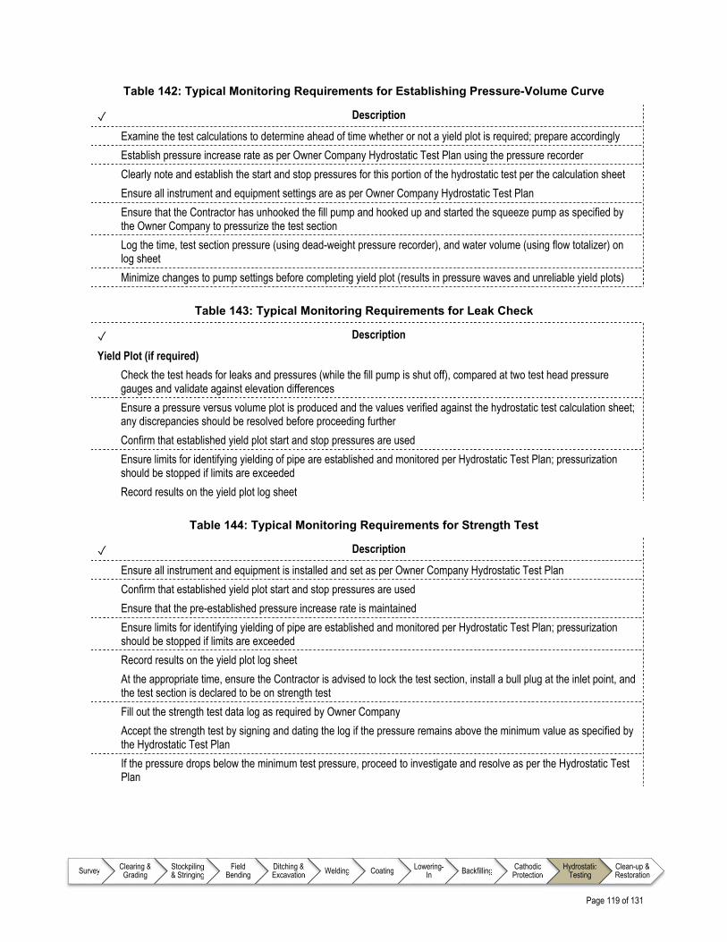
Page 119 of 131
Survey Clearing & Grading
Stockpiling & Stringing
Field Bending
Ditching & Excavation Welding Coating Lowering-
In Backfilling Cathodic Protection
Hydrostatic Testing
Clean-up & Restoration
Table 142: Typical Monitoring Requirements for Establishing Pressure-Volume Curve
✓ Description
Examine the test calculations to determine ahead of time whether or not a yield plot is required; prepare accordingly
Establish pressure increase rate as per Owner Company Hydrostatic Test Plan using the pressure recorder
Clearly note and establish the start and stop pressures for this portion of the hydrostatic test per the calculation sheet
Ensure all instrument and equipment settings are as per Owner Company Hydrostatic Test Plan
Ensure that the Contractor has unhooked the fill pump and hooked up and started the squeeze pump as specified by the Owner Company to pressurize the test section
Log the time, test section pressure (using dead-weight pressure recorder), and water volume (using flow totalizer) on log sheet
Minimize changes to pump settings before completing yield plot (results in pressure waves and unreliable yield plots)
Table 143: Typical Monitoring Requirements for Leak Check
✓ Description
Yield Plot (if required)
Check the test heads for leaks and pressures (while the fill pump is shut off), compared at two test head pressure gauges and validate against elevation differences
Ensure a pressure versus volume plot is produced and the values verified against the hydrostatic test calculation sheet; any discrepancies should be resolved before proceeding further
Confirm that established yield plot start and stop pressures are used
Ensure limits for identifying yielding of pipe are established and monitored per Hydrostatic Test Plan; pressurization should be stopped if limits are exceeded
Record results on the yield plot log sheet
Table 144: Typical Monitoring Requirements for Strength Test
✓ Description
Ensure all instrument and equipment is installed and set as per Owner Company Hydrostatic Test Plan
Confirm that established yield plot start and stop pressures are used
Ensure that the pre-established pressure increase rate is maintained
Ensure limits for identifying yielding of pipe are established and monitored per Hydrostatic Test Plan; pressurization should be stopped if limits are exceeded
Record results on the yield plot log sheet
At the appropriate time, ensure the Contractor is advised to lock the test section, install a bull plug at the inlet point, and the test section is declared to be on strength test
Fill out the strength test data log as required by Owner Company
Accept the strength test by signing and dating the log if the pressure remains above the minimum value as specified by the Hydrostatic Test Plan
If the pressure drops below the minimum test pressure, proceed to investigate and resolve as per the Hydrostatic Test Plan

Page 120 of 131
Survey Clearing & Grading
Stockpiling & Stringing
Field Bending
Ditching & Excavation Welding Coating Lowering-
In Backfilling Cathodic Protection
Hydrostatic Testing
Clean-up & Restoration
Table 145: Typical Monitoring Requirements for Leak Test
✓ Description
Ensure pressure reduction from strength test value to leak test value is completed in a manner consistent with Hydrostatic Test Plan
All other monitoring requirements are similar to Strength Test per Table 144
Table 146: Typical Monitoring Requirements for Leak or Failure Investigation
✓ Description
Advise the Owner Company of further action in the event that the Contractor cannot locate a pipe leak or determine the cause of failure during hydrostatic testing through visual inspection
Notify the Construction Manager / Chief Inspector (or designate) and work with the Contractor to develop a Leak Detection Plan and have it approved
When a leak is discovered, ensure the Contractor repairs the leak per Owner Company specifications and other portions of this document are referenced prior to conducting the hydrostatic test again
Table 147: Typical Monitoring Requirements for Depressurizing
✓ Description
Ensure that the Contractor does not start depressurizing until all required personnel are on site
Confirm that the Contractor has taken all safety precautions before starting to depressurize the test section
Check that the Contractor has secured the depressurizing hose to prevent vibration during pressure release
Ensure that the Contractor is opening the test head slowly to protect it from shock-loading the pipeline
Ensure that the Contractor or other personnel does not, under any circumstance, open the bleed-off assembly fully
Table 148: Typical Monitoring Requirements for Dewatering
✓ Description
Ensure that the Contractor does not start dewatering until all required personnel are on site
Ensure that the Contractor dewaters to locations approved in the water permit or the Environmental Protection Plan (EPP)
Ensure that the Contractor does not dewater until proper fill-water sampling is completed and filtration unit is in place (if required)
Check that the Contractor securely supports and ties down the dewatering line at the discharge end to prevent whipping
Confirm that the Contractor does not use mechanical connections on dewatering line
Ensure that the Contractor installs an energy absorbing diffuser at the discharge end of the dewatering line to prevent erosion, bottom scour, or damage to vegetation
Check that the Contractor uses a bi-directional pig propelled by compressed air to push water out of the test section
Check that the Contractor probes the dewatering pigs to verify their proper position before and after dewatering runs
Ensure that the test section is dewatered based on the specified procedure, in particular: Appropriate pressure set points and pig speed are maintained A test section with a downhill slope is dewatered with the appropriate precautions as identified per the
Hydrostatic Test Plan (e.g., the discharge end valve should not be opened before receiving the pig) Additional specific seasonal considerations may also apply

Page 121 of 131
Survey Clearing & Grading
Stockpiling & Stringing
Field Bending
Ditching & Excavation Welding Coating Lowering-
In Backfilling Cathodic Protection
Hydrostatic Testing
Clean-up & Restoration
Table 149: Typical Monitoring Requirements for Test Head Removal / Replacement
✓ Description
Inspect for damage and unfit fittings once test head is removed
Check that sacrificial pup is removed and nuts, studs, and valves are properly secured for transport
Complete test head inspection documentation
Ensure heavy wall pipe end is prepared for welding during final tie-ins
Table 150: Typical Monitoring Requirements for Drying
✓ Description
General
Confirm that drying method used by Contractor is consistent with Hydrostatic Test Plan requirements
Ensure that Owner Company criteria for a “dry line” are met
If the pipeline will not be commissioned soon after drying, ensure the pipeline is purged with dry nitrogen to meet Owner Company specifications
Drying Pig Runs
Ensure pigs used for drying runs are as specified by the Owner Company
Confirm that number of pig runs is per Owner Company requirements (each pig should be numbered)
Ensure that all drying pigs are counted upon receipt (i.e., ensure no pigs remain in the line)
Air Drying
Ensure injected dried air relative humidity readings meet specifications
Methanol Wash
If Owner Company has specified methanol wash as the acceptable drying method, ensure specifications for injection and recovery are followed

Page 122 of 131
Survey Clearing & Grading
Stockpiling & Stringing
Field Bending
Ditching & Excavation Welding Coating Lowering-
In Backfilling Cathodic Protection
Hydrostatic Testing
Clean-up & Restoration
17.7 Typical Outputs for Hydrostatic Testing Inspection
Table 151: Typical Reporting Requirements
✓ Description
General
Record all hydrostatic test calculations and results
Complete Safety Hazard Observation Report
Complete test head inspection documentation
Establishing Pressure-Volume Curve – Log the time, test section pressure (using dead-weight pressure recorder), and water volume (using flow totalizer) on log sheet
Leak Check – Record results on the yield plot log sheet
Strength Test – Fill out the strength test data log as required by Owner Company
Daily
Complete hydrostatic testing progress reports, including: Any and all of the monitoring and inspection items as defined in previous tables within Section 17.0
References – Hydrostatic Testing
Note to user: The reference information provided in Table 152 is intended as a guide only (i.e., the list is not exhaustive); documents of this nature are updated frequently and it remains the responsibility of the user to ensure that the correct, and most current, documents are referenced as appropriate.
Table 152: List of References – Hydrostatic Testing
Document No. Type Title
American Petroleum Institute (API)
API RP 1110 Recommended Practice Pressure Testing of Steel Pipelines for the Transportation of Gas, Petroleum Gas, Hazardous Liquids, Highly Volatile Liquids, or Carbon Dioxide
INGAA Foundation
CS-S-9 Guideline Construction Safety Consensus Guidelines – Pressure Testing (Hydrostatic /Pneumatic) Safety Guidelines

Page 123 of 131
Survey Clearing & Grading
Stockpiling & Stringing
Field Bending
Ditching & Excavation Welding Coating Lowering-
In Backfilling Cathodic Protection
Hydrostatic Testing
Clean-up & Restoration
18.0 CLEAN-UP AND RESTORATION
18.1 Overview
Construction site clean-up is the final cleaning and removal of construction materials left over from the pipeline right of way (ROW) and surrounding area. All materials not native to the site are removed. Construction site clean-up is important to the Owner Company as it:
Provides tangible examples of Owner Company’s attention to detail during construction
Helps to ensure regulatory agencies and Land Owners are satisfied
Sets the stage for Land Owner acquiescence, agreement, and support when approached for future projects
Clean-up work can be performed in phases depending on the location and season of construction. For example, during winter construction, the Contractor will perform the machine or initial clean-up immediately after the end of construction and before the spring breakup, then return to the site the following winter to do the final clean-up. However, during summer construction, the Contractor will do both machine and final clean-up immediately after the end of construction and return to the site at a later date for additional restoration work (e.g., repairing a sunken ditch).
18.2 Inputs
As part of preparing for inspection during the clean-up and restoration process, the Inspector will continually familiarize themselves with relevant aspects of key documents, drawings, and Owner Company technical specifications as identified in Table 154.
18.3 Execution
While the work is being executed, the Inspector is required to monitor workmanship and report on progress on a periodic basis. Typical items that the Inspector will monitor for during the clean-up and restoration process are identified in a series of checklists as detailed in Table 153.

Page 124 of 131
Survey Clearing & Grading
Stockpiling & Stringing
Field Bending
Ditching & Excavation Welding Coating Lowering-
In Backfilling Cathodic Protection
Hydrostatic Testing
Clean-up & Restoration
Table 153: Monitoring Requirements for Clean-up and Restoration
Item Description Reference
Prior to Commencing Work
On a daily basis, ensure key issues that have been identified are detailed and addressed
Table 155
Safety Monitor the operations for adherence to relevant Owner Company and project specific safety requirements
Table 156
Environmental Considerations
Identifies specific items that should be monitored throughout Clean-up and Restoration operations that relate specifically to the Owner Company and/or project specific Environmental Protection Plan (EPP)
Table 157
General Clean-up and Restoration
Monitor to ensure that condition of the ROW and construction area is returned as close to the original state as possible, also taking into consideration Land Owner concerns
Table 158
Topsoil Replacement Ensure that topsoil quality is per Owner Company specification and Land Owner agreements as part of ROW rehabilitation
Table 159
Terraces, Drainage, and Slope Protection
Confirm that appropriate drainage and slope protection mechanisms have been installed as required by Owner Company specifications
Table 160
Diversion Berms Ensure Diversion Berms (shallow earthen dykes that collect and redirect surface water on right of way) are constructed as required following Owner Company specifications
Table 161
Watercourses and Crossings
Confirm that watercourses and crossings are treated as per requirements of any permits as well as required by Owner Company specifications
Table 162
Roads Confirm that roads have been returned to a state as per Owner Company specifications, road crossing, and Land Owner agreements
Table 163
Replanting and Reseeding
Confirm that replanting and reseeding is completed as per requirements of any permits as well as required by Owner Company specifications
Table 164
Fencing Confirm that fencing has been installed as per Owner Company specifications and Land Owner agreements
Table 165
18.4 Outputs
The Inspector is required to report on workmanship and progress on a periodic basis (e.g., daily or weekly) by completing various reports on each work day and end of week. Report requirements and reporting processes are Owner Company and project specific; however, best practices for reporting requirements for clean-up and restoration appear in Table 166.

Page 125 of 131
Survey Clearing & Grading
Stockpiling & Stringing
Field Bending
Ditching & Excavation Welding Coating Lowering-
In Backfilling Cathodic Protection
Hydrostatic Testing
Clean-up & Restoration
Detailed Checklists – Clean-up and Restoration
18.5 Typical Input Requirements for Clean-up and Restoration Inspection
Table 154: Information Requirements for Clean-up and Restoration
✓ Description
All designs, drawings, and specifications developed by the Owner Company and Contractors related to clean-up and restoration, such as: Access Road Drawings Grading Drawings Line List (e.g., special concerns for each Land Owner)
Contracts and agreements related to: Road Use Crossing for Buried Facilities Construction Survey
Permits related to: Environmental Road Use
Owner Company specific Safety Plan, including (but not limited to): Traffic Control Plan Requirements for Personal Protective Equipment (PPE) Procedures for working around overhead powerlines Emergency Medical Services (EMS)
Project specific Environmental Protection Plan (EPP) detailing clean-up and restoration requirements for the following (but not limited to): Watercourses Wetlands, muskeg, and swamp areas Wildlife habitats Migratory routes
Other project specific Plans, which may include: Approved Grading Plan Clean-up and ROW Restoration Plan Heritage Sites

Page 126 of 131
Survey Clearing & Grading
Stockpiling & Stringing
Field Bending
Ditching & Excavation Welding Coating Lowering-
In Backfilling Cathodic Protection
Hydrostatic Testing
Clean-up & Restoration
18.6 Best Practice Items for Inspecting Typical Clean-up and Restoration Operations
Table 155: Prior to Commencing Work
✓ Description
Participate in daily meetings to address: Job safety and/or hazard identification issues Environmental concerns Duties of Inspector(s) Pipeline Contractor’s tailgate meetings (as required) Ad-hoc meetings with Contractors to discuss and clarify questions or concerns
Table 156: Safety Concerns for Clean-up and Restoration
✓ Description
There are no incremental specific Safety Concerns beyond those identified in chapter 6.0 Pipeline Construction Inspector – Foundational Information
Table 157: Typical Monitoring Requirements for Environmental Considerations
✓ Description
There are no incremental specific Environmental Considerations beyond those identified in chapter 6.0 Pipeline Construction Inspector – Foundational Information
Table 158: Typical Monitoring Requirements for General Clean-up and Restoration
✓ Description
Liaise with Land Agent on any special restoration requirements of Land Owners Ensure complete removal of debris (e.g., general construction debris, rocks, boulders) Ensure that previously existing contours in landscape are recreated Check placement of erosion control measures for compliance with Owner Company specifications Ensure that ROW preparation is suitable for the application of fertilizers and seeds per Owner Company specifications
as well as Land Owner agreements Ensure that appropriate equipment is used to remove compaction Ensure no surplus construction or pipeline materials are left on the ROW (refer to contract documents to determine
which materials will be stored and which will be scrapped) Confirm that reusable materials (e.g., pipe sections, valves, coating material) were returned to Owner Company after
being prepared for return Confirm the backfill roach is not blocking any drainage, access roads, recreational trails, or wildlife/livestock trails
across the ROW and that sufficient gaps have been included to allow cross-drainage Ensure that for winter construction, the ROW is stabilized after construction and during machine clean-up to prevent
erosion during the spring thaw. Final clean-up may be completed during the following construction season, either fall or winter, depending on ground conditions
Confirm that the Contractor will conduct final clean-up when soils are dry and unfrozen Check that all required diversion berms have been built Ensure cathodic protection test leads at all test stations are installed at specified heights on supporting poles
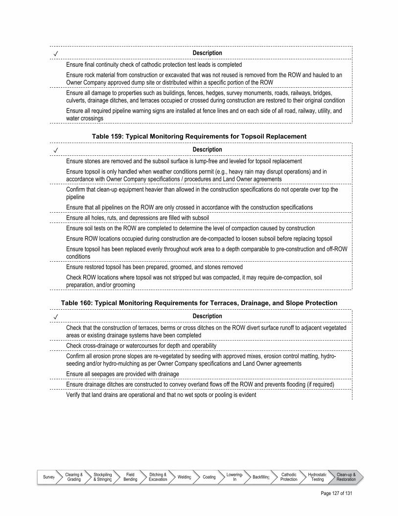
Page 127 of 131
Survey Clearing & Grading
Stockpiling & Stringing
Field Bending
Ditching & Excavation Welding Coating Lowering-
In Backfilling Cathodic Protection
Hydrostatic Testing
Clean-up & Restoration
✓ Description
Ensure final continuity check of cathodic protection test leads is completed Ensure rock material from construction or excavated that was not reused is removed from the ROW and hauled to an
Owner Company approved dump site or distributed within a specific portion of the ROW Ensure all damage to properties such as buildings, fences, hedges, survey monuments, roads, railways, bridges,
culverts, drainage ditches, and terraces occupied or crossed during construction are restored to their original condition
Ensure all required pipeline warning signs are installed at fence lines and on each side of all road, railway, utility, and water crossings
Table 159: Typical Monitoring Requirements for Topsoil Replacement
✓ Description
Ensure stones are removed and the subsoil surface is lump-free and leveled for topsoil replacement
Ensure topsoil is only handled when weather conditions permit (e.g., heavy rain may disrupt operations) and in accordance with Owner Company specifications / procedures and Land Owner agreements
Confirm that clean-up equipment heavier than allowed in the construction specifications do not operate over top the pipeline
Ensure that all pipelines on the ROW are only crossed in accordance with the construction specifications
Ensure all holes, ruts, and depressions are filled with subsoil
Ensure soil tests on the ROW are completed to determine the level of compaction caused by construction
Ensure ROW locations occupied during construction are de-compacted to loosen subsoil before replacing topsoil
Ensure topsoil has been replaced evenly throughout work area to a depth comparable to pre-construction and off-ROW conditions
Ensure restored topsoil has been prepared, groomed, and stones removed
Check ROW locations where topsoil was not stripped but was compacted, it may require de-compaction, soil preparation, and/or grooming
Table 160: Typical Monitoring Requirements for Terraces, Drainage, and Slope Protection
✓ Description
Check that the construction of terraces, berms or cross ditches on the ROW divert surface runoff to adjacent vegetated areas or existing drainage systems have been completed
Check cross-drainage or watercourses for depth and operability
Confirm all erosion prone slopes are re-vegetated by seeding with approved mixes, erosion control matting, hydro-seeding and/or hydro-mulching as per Owner Company specifications and Land Owner agreements
Ensure all seepages are provided with drainage
Ensure drainage ditches are constructed to convey overland flows off the ROW and prevents flooding (if required)
Verify that land drains are operational and that no wet spots or pooling is evident

Page 128 of 131
Survey Clearing & Grading
Stockpiling & Stringing
Field Bending
Ditching & Excavation Welding Coating Lowering-
In Backfilling Cathodic Protection
Hydrostatic Testing
Clean-up & Restoration
Table 161: Typical Monitoring Requirements for Diversion Berms
✓ Description
Ensure construction of terraces, berms or cross ditches on the ROW to divert surface runoff to adjacent vegetated areas or existing drainage systems are completed
Ensure all seepages are provided with drainage
If required, ensure drainage ditches are constructed to convey overland water flows off the right of way to prevent flooding
Ensure berms are prepared for seeding
Table 162: Typical Monitoring Requirements for Watercourses and Crossings
✓ Description
Ensure water crossings are restored to pre-construction conditions and erosion and sediment control measures are installed per Owner Company specifications, Land Owner agreements, or as required
Ensure riparian zones at major creek and river crossings are stabilized by supplying and installing site specific reclamation
Ensure water quality is maintained while applying erosion control at a watercourse
Table 163: Typical Monitoring Requirements for Roads
✓ Description
Confirm that all temporary access roads built during construction are removed and reclaimed per contract requirements
Ensure road surfaces, fences and gates, signs, etc. are replaced or restored per contract requirements
Ensure road system drainage tile systems are repaired, modified and/or replaced per contract requirements
Ensure side-cuts are sloped and filled to stable angles to prevent incidents to persons, livestock, wildlife, or the environment
Table 164: Typical Monitoring Requirements for Replanting and Reseeding
✓ Description
Confirm that the final soil surface is prepared adequately for seeding, taking soil conditions, weather conditions, ROW requirements, and surrounding land use into consideration
Confirm all seed mixes, fertilizers, and rates of application have been approved by Owner Company and Land Owner agreements
Confirm all seed and fertilizer application equipment and techniques have been approved by Owner Company using an approved technique such as seed drills or mechanical / hand broadcasters
Ensure areas where soil stabilization is required (e.g., slopes, stream banks) have been seeded, fertilized, hydro-seeded, or sprayed with a tackifier (a soil adhesive) / mulch mixture
Ensure trees and shrubs have been replanted or transplanted to meet Owner Company specifications and Land Owner agreements
Ensure all original vegetation, including seeds, sod, grass, shrubs, and trees are restored or replaced, including fertilizing per Owner Company specifications and Land Owner agreements

Page 129 of 131
Survey Clearing & Grading
Stockpiling & Stringing
Field Bending
Ditching & Excavation Welding Coating Lowering-
In Backfilling Cathodic Protection
Hydrostatic Testing
Clean-up & Restoration
Table 165: Typical Monitoring Requirements for Fencing
✓ Description
Ensure all temporary fences and barricades that were erected to stop unauthorized access by people or livestock (e.g., at the worksite, road crossings, access roads, or to identify sensitive locations like water crossing approaches and heritage resource sites) have been removed per Owner Company specifications
Ensure that all fencing at compressor, sales / receipt meter stations, and valve locations that has been dismantled for convenience of work has been restored or replaced
Ensure that sections of existing fence and gates that were removed have been supplied and replaced with new fence materials and new gates

Page 130 of 131
Survey Clearing & Grading
Stockpiling & Stringing
Field Bending
Ditching & Excavation Welding Coating Lowering-
In Backfilling Cathodic Protection
Hydrostatic Testing
Clean-up & Restoration
18.7 Typical Outputs for Clean-up and Restoration Inspection Reporting
Table 166: Typical Reporting Requirements
✓ Description
General
There are no incremental specific reporting requirements beyond those identified in chapter 6.0 Pipeline Construction Inspector – Foundational Information
Daily
Complete clean-up and restoration progress reports, including the following details: Daily progress of the Contractor’s clean-up activities with starts and end chainages / station numbers of daily
progress Daily updates on start and end chainages / station numbers of locations where the Contractor did no clean-up
with a detailed explanation for omission Any ROW, weather, or other logistical conditions that caused either an increase or decrease in expected
progress Depth of replaced topsoil Compaction depths Start / stops on tackifier applications Start / stops on any specialized compaction removal Drain tile station locations Temporary / permanent repairs performed (e.g., fence damage) Location and type of sediment control measures installed Installation of additional warning signs
References – Clean-up and Restoration
Note to user: The reference information provided in Table 167 is intended as a guide only (i.e., the list is not exhaustive); documents of this nature are updated frequently and it remains the responsibility of the user to ensure that the correct, and most current, documents are referenced as appropriate.
Table 167: List of References – Clean-up and Restoration
Document No. Type Title
There are no incremental specific reference documents beyond those identified in chapter 6.0 Pipeline Construction Inspector – Foundational Information

Page 131 of 131
ENDNOTE
This Guide was developed by the INGAA Foundation and CEPA Foundation for the use of Pipeline Construction Inspectors in North America. This is the original version and is subject to future revision. If you have any suggestions on additional content or revision to the material included in this Guide, please contact:
Executive Director or Executive Director
The CEPA Foundation The INGAA Foundation
Suite 200, 505-3rd St. SW 20 F St.; Suite 450
Calgary, AB T2P 3E6 Washington, DC 20001
1 (403) 221 - 8779 1 (202) 216 - 5909