reverse flotation studies onanindian lowgrade ironoreslimes
TRANSCRIPT

T.V.Vijayakumar. et. al. / International Journal of Engineering Science and TechnologyVol. 2(4), 2010, 637-648
Reverse flotation studies on an Indianlow grade iron ore slimes
National Metallurgical Laboratory - Madras Centre,CSIR Madras Complex, Taramani, Chennai - 600 113, India
·*Present address: Mineralogy Department,Institute of Minerals and Materials Technology,
Bhubaneswar -751013, Orissa, India
The present investigation deals with the recovery of iron values from the screw classifier overflow slimes froman iron ore washing plant by means of reverse cationic flotation as an alternate to direct anionic flotation.Selectivity index, an indicator of separation efficiency, was chosen as the response parameter for optimizing thequantity and evaluating a series of generically same but chemically different cationic collectors used in reverseflotation and for further optimization of other flotation process parameters. In the optimization, the mainvariables investigated were percent solids, collector and depressant dosage. An increase in the iron content ofthe concentrates is obtained with concomitant reduction in Si02 and Ah03levels.
Most of the iron ore mines in India produce hematite ores and have washing plants to produce lumps as well asfines. In this process, a part of the fine gangue material is removed from the product. During the washingprocess, around 8-10 million tons of slimes containing around 48-60% of Fe are discarded every year (Prakashet al., 2000). These slimes can not be used in iron making as they contain higher amount of gangue (Senguptaand Prasad, 1990). Since metallurgy of steel demands high grade iron ore concentrates with a low percentage ofgangue (Si02 and Ah03), the present study is confined to an iron ore mine at Joda East (22°01'15" - 22°0 1'26" Nlatitude; 85OZ5'13" - 85OZ5'20" E longitude), Keonjhar district, Orissa. Joda East Iron ore Mine (JEIM) is part ofthe volcano-sedimentary basins containing iron ore deposits belonging to the Iron Ore Group (lOG) of ArchaeanSinghbhum Craton. Details of mineralogy and geochemistry of this deposit has been dealt in detail by Nayak etal., (1998). A beneficiation plant has been in operation with the primary objective of reducing alumina in ironore at different stages of processing. The unit operations in the flow sheet comprise of three-stage crushing ofRun Of Mine (ROM), scrubbing, dry/wet screening, classification of undersize of wet screening by screwclassifiers followed by hydro-cycloning of screw classifiers' overflow. The underflow of hydro-cyclones is sentto the fines surge pile for further dispatch. Possibilities of further improvement in the recovery of iron valuesfrom the screw classifier overflow by flotation, as compared to that which is being obtained presently in thehydrocyclones, was investigated. Accordingly, iron ore slime sample was drawn from overflow of screwclassifier to conduct bench scale laboratory studies by flotation as a prelude to detailed further studies.
The beneficiation of iron ore slime produced from washing plants and tailing ponds of Kiriburu mines wasstudied (Prasad et al., 1988) using wet high intensity magnetic separator followed by classification in ahydrocyclone. They showed that a concentrate assaying 63% Fe and 3.3% alumina could be produced with anoverall iron recovery of 56%. Similarly Das et al. (1995) studied iron ore slimes from Barsua, Bolani andKiriburu using classification by hydrocyclone followed by high intensity magnetic separation. Their resultsindicated that a concentrate assaying 60-65% Fe with 60-80% recovery can be achieved. Multigravity separatoris a useful technique for treating iron ore slime and is particularly effective in reducing alumina content (Pradip,1994). However, it is not very successful commercially due to its low capacity (Roy and Das, 2008). All theseearlier works indicates that beneficiation of iron ore slimes containing significant amount of Fe along with Si02and Ah03 is quite difficult. It is also equally difficult to know the characteristics of these slimes where most ofthe particles are below 50 microns. Hence, in the present case, reverse flotation process was adopted to study asthere was no literature available to date for treating Indian iron ore slimes by this method.

T.V.Vijayakumar. et. al. / International Journal of Engineering Science and TechnologyVol. 2(4), 2010, 637-648
The iron ores are generally concentrated mostly by gravity and magnetic methods and in fewer instances byflotation. The choice of beneficiation methods mostly depends on the grain size of the sample which ultimatelyis based on the liberation of iron-bearing minerals from the gangue. The gravity and magnetic methods arerestricted to coarse grain size particles and these methods have their own limitations when the particle size isfine such as in iron ore slimes. When the test sample contains relatively lesser gangue, it is easier to float it andhence reverse flotation can be employed rather than direct flotation wherein major proportion of thematerial,otherwise, would have to be floated. As such,the reverse flotation is the usual process for thebeneficiation of iron ore slimes. Amines are the only cationic collectors used by industries in reverse flotation ofiron ores. This reagent ionizes in water solution by protonation (Leja, 1985). Pankratov and Skorodumova(1970) concluded that Reverse flotation provides a higher beneficiation efficiency of slimes.
Characterisation studies of this screw classifier overflow iron ore sample consisted of various steps including itssize analysis, chemical analysis and X-Ray Diffraction study and heavy liquid separation. These steps aredescribed in detail in the following sections and corresponding observations are presented.
Size analysis: In order to collect samples of each size range, sieving of iron ore sample was carried out. Forseparation of -50IJlll particles micro-precision sieves were used. About 77% of the feed consists of -37 IJm sizefraction. It is seen from the size analysis that the sample is extremely fine in nature with d80 = 45.6 IJm. DetailedParticle Size Analysis done by manual wet sieving is given in the following Table - I.
S.No.Size, Weight, Assav. % LOI,% Dist. %urn % Fe Sia2 Aha) (Calc.) Fe Sia2 Aha)
I +150 3.10 50.60 7.98 10.64 8.82 2.63 4.61 5.67
2 +125 1.51 55.00 6.54 9.07 5.54 1.39 1.84 2.35
3 +106 1.88 57.60 5.16 7.88 4.39 1.82 1.81 2.55
4 +90 3.38 58.80 4.30 6.78 4.64 3.34 2.71 3.94
5 +75 3.73 59.30 4.21 6.40 4.39 3.71 2.93 4.10
6 +63 0.98 59.60 4.20 6.36 4.01 0.98 0.77 1.07
7 +53 3.69 59.80 3.99 5.90 4.40 3.71 2.74 3.74
8 +45 1.50 59.10 4.64 6.44 4.46 1.49 1.30 1.66
9 +37 3.37 59.50 4.48 6.35 3.89 3.37 2.81 3.68
10 -37 ·76.86 60.10 5.48 5.39 2.99 77.56 78.48 71.24
Head (Calculated) 59.56 5.37 5.82 3.46 100.00 100.00 100.00
Head (Assay) 58.70 5.30 5.79 5.34
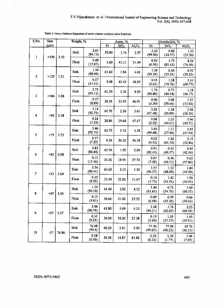
Heavy liquid separation: Characterization was also performed by sink and float studies to assess the liberation ofiron minerals from !he gangue. Individual sieve fractions in the previous washing-cum-wet sieving test weresubjected to heavy medium separation using tetrabromoethane (specific gravity 2.967) to elicit information onliberation characteristics of the sample and the results are tabulated and presented in the Table-2. Figures inparentheses indicate the weight percentage contribution of each entity (sink & float) in the respective sizefraction.

T.V.Vijayakumar. et. al. / International Journal of Engineering Science and TechnologyVol. 2(4), 2010, 637-648
Chemical composition: The chemical composition of the various fractions is carried out by conventional wetchemical analysis method and presented in Table I. The data in the Table 1 shows -37 J.lIl1are richer in assay aswell as Fe distribution. The -37 J.lIl1also shows least LOI compared to other sieve fractions. It is characterizedby presence of higher distribution levels ofLOI, Fe, Si02 and Ah03 with respect to feed. It can be inferred fromfloat & sink test on -37 J.lm size fraction that Fe, Si02 and Ah03 bearing minerals are in interlocked state asmajority of them (99.670/0, 98.23% and 92.31 % respectively) reported to the sink fraction. Float & Sink tests onother size fractions also bear same conclusion with none of the sink fractions containing less than 3.0% A1203,but for sink of +150 J.lm size fraction at 2.97%. Improvement in %Fe in sink portion of size fractions -90+75J.lm, -75+63 J.lm, -63+53 J.lm took place at the expense of % Si02, bulk of which had reported to float portionbecause of fairly good liberation. This further substantiates that the interlocking between iron oxides andalumina bearing minerals is more predominant than that between iron oxides and silica bearing minerals. By andlarge, liberation characteristics of the material are poor across all size ranges. From this, it is anticipated thatmarginal improvement in grade can take place that too at the expense of silica but not alumina.
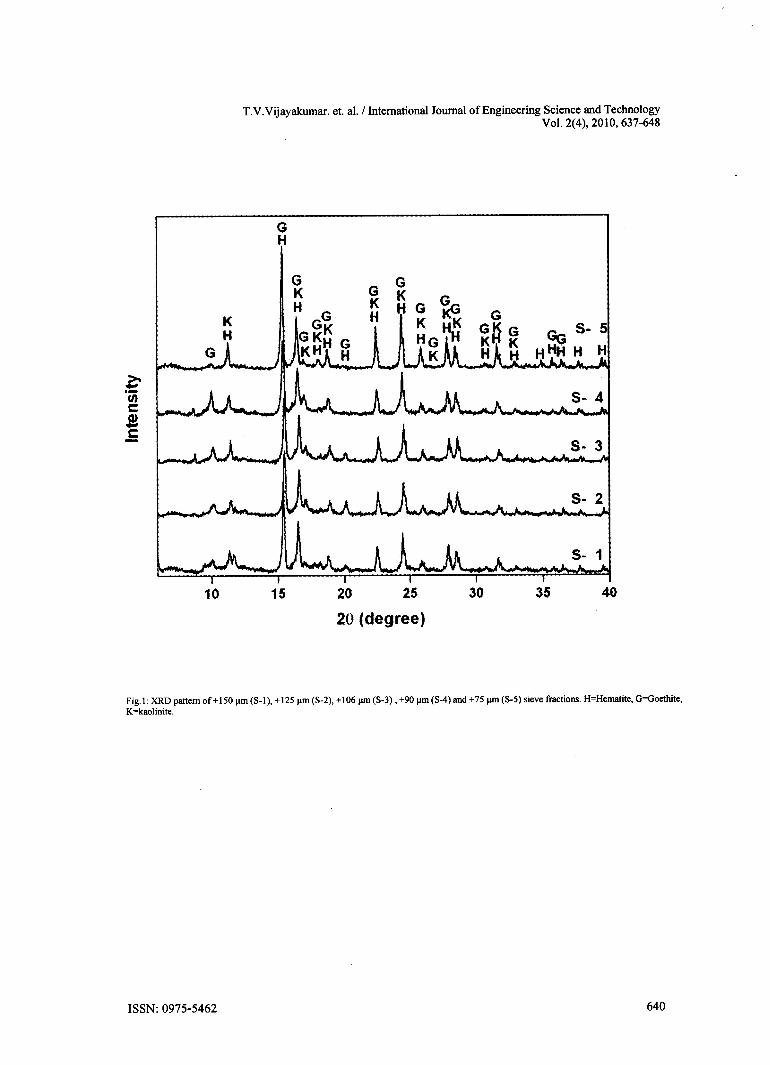
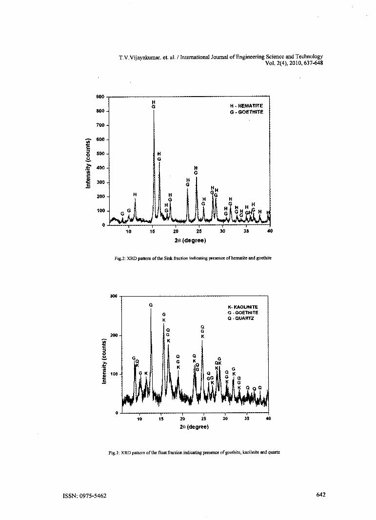
XRD study: The XRD study was carried out to identitY the mineral phases present in different sieve fractionsthe sample. The +150, +125, +106, +90 and +75 J.lIl1sieve fractions were chosen for the XRD study as theycontain highest amount of the alumina. The diffractogarm is shown in the Fig.l. From the figure it is clear thatthe hematite and goethite are the iron bearing mineral phases. Kaolinite occurs as minor gangue phase. Thoughquartz is present in minor quantities but not reflected in the XRD patterns. These quartz and kaolinite are thesilicate gangue mainly contributing towards the silica and alumina respectively in the sample. The sink (Fig.2)and float (Fig.3) fraction was also subjected to XRD studies. From the figures it is clear that the hematite andgoethite are the only mineral phases whereas the float fraction shows presence of quartz, kaolinite and goethite.
T.V.Vijayakumar. et. al. / International Journal of Engineering Science and TechnologyVol. 2(4), 2010, 637-648
20 25
20 (degree)
Fig.l: XRD pattern of+150 I'ffi (8-1), + 125 I'ffi (8-2), +106 I'ffi (8-3), +90 I'ffi (8-4) and +751'ffi (8-5) sieve fractions. H=Hematite, G=Goethite,K=kaolinite.
T.V.Vijayairumar. et. al. / International Journal of Engineering Science and TechnologyVol. 2(4), 2010, 637-648
S.No. Size Weight, % Assay, % Distribution, %(urn) Fe Si02 Ah03 Fe Si02 AI203
Sink 2.6159.80 1.76 2.97 2.62 0.86 1.33
(84.13) (99.50) (18.57) (23.50)1 +150 3.10
Float0.49
1.60 41.11 51.49 0.01 3.75 4.34(15.87) (0.50) (81.43) (76.50)
Sink1.34
61.60 1.86 4.011.38 0.46 0.92
2 +125 1.51(88.69) (99.39) (25.24) (39.23)
Float0.17
2.98 43.43 48.95 0.01 1.38 1.43(11.31) (0.61) (74.76) (60.77)
Sink1.71
61.30 2.30 4.001.76 0.73 1.18
3 +106 1.88(91.11) (96.80) (40.54) (46.17)
Float0.17 20.38 33.93 46.91 0.06 1.08 1.37
(8.89) (3.20) (59.46) (53.83)
Sink 3.14 61.70 2.36 3.67 3.26 1.38 1.98
4 +90 3.38(92.75) (97.48) (50.99) (50.29)
Float 0.24 20.86 29.68 47.47 0.08 1.33 1.96(7.25) (2.52) (49.01) (49.71)
Sink 3.4663.70 1.72 3.28 3.69 1.11 1.95
(92.75) (99.48) (37.90) (47.54)5 +75 3.73
Float 0.274.26 36.12 46.38 0.02 1.82 2.15
(7.25) (0.52) (62.10) (52.46)
Sink 0.85 63.50 1.95 3.09 0.91 0.31 0.45
6 +63 0.98(86.44) (92.41 ) (40.27) (42.14)
Float0.13
34.10 18.91 27.74 0.07 0.46 0.62(13.56) (7.59) (59.73) (57.86)
Sink 3.34 63.60 2.12 3.203.57 1.32 1.84
7 +53 3.69(90.44) (96.27) (48.09) (49.09)
Float 0.35 23.54 21.92 31.67 0.14 1.42 1.90(9.56) (3.73) (51.91) (50.91)
Sink1.35
61.60 2.82 4.321.40 0.71 1.00
8 +45 1.50(90.19) (93.81) (54.70) (60.37)
Float0.15
36.60 21.02 25.52 0.09 0.59 0.66(9.81) (6.19) (45.30) (39.63)
Sink 3.06 61.80 3.09 4.23 3.18 1.76 2.23(90.79) (94.31) (62.63) (60.49)
9 +37 3.37Float 0.31 36.80 18.20 27.28 0.19 1.05 1.45
(9.21) (5.69) (37.37) (39.51)
Sink76.48 60.20 5.41 5.00
77.30 77.09 65.76(99.5) (99.67) (98.23) (92.31)
10 -37 76.86Float 0.38 30.38 14.87 83.88
0.26 1.39 5.48(0.50) (0.33) (1. 77) (7.69)
T.V.Vijayakumar. et. at. / International Journal of Engineering Science and TechnologyVol. 2(4), 2010, 637-648
$00HG H·HEMATITE800 G·GOETHITE
700
- 600InC:J 500 H0CJ G-~ 400 H"iij Gc:~
300 HG
200 H
100
020 25
20 (degree)
K. KAOLINITEG • GOETHITEQ·QUARTZ
20 25
20 (degree)
T.V.Vijayakumar. et. al. / International Journal of Engineering Science and TechnologyVol. 2(4), 2010, 637-648
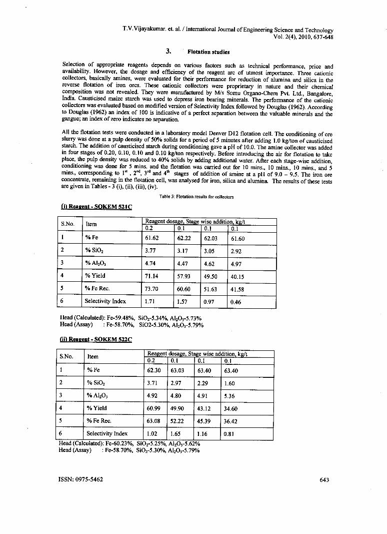
Selection of appropriate reagents depends on various factors such as technical performance, price andavailability. However, the dosage and efficiency of the reagent are of utmost importance. Three cationiccollectors, basically amines, were evaluated for their performance for reduction of alumina and silica in thereverse flotation of iron ores. These cationic collectors were proprietary in nature and their chemicalcomposition was not revealed. They were manufactured by Mis Somu Organo-Chem Pvt. Ltd., Bangalore,India. Causticised maize starch was used to depress iron bearing minerals. The performance of the cationiccollectors was evaluated based on modified version of Selectivity Index followed by Douglas (1962). Accordingto Douglas (1962) an index of 100 is indicative of a perfect separation between the valuable minerals and thegangue; an index of zero indicates no separation.
All the flotation tests were conducted in a laboratory model Denver DI2 flotation cell. The conditioning of oreslurry was done at a pulp density of 50% solids for a period of 5 minutes after adding 1.0 kg/ton of causticisedstarch. The addition of causticised starch during conditioning gave a pH of 10.0. The amine collector was addedin four stages of 0.20, 0.10, 0.10 and 0.10 kg/ton respectively. Before introducing the air for flotation to takeplace, the pulp density was reduced to 40% solids by adding additional water. After each stage-wise addition,conditioning was done for 5 mins. and the flotation was carried out for 10 mins., 10 mins., 10 mins., and 5mins., corresponding to 1st ,2nd, 3rd and 4th stages of addition of amine at a pH of 9.0 - 9.5. The iron oreconcentrate, remaining in the flotation cell, was analysed for iron, silica and alumina. The results of these testsare given in Tables - 3 (i), (ii), (iii), (iv).
S.No. Item Rell2ent dosll2e Staj1;ewise addition, kg/t0.2 0.1 0.1 0.1
I %Fe 61.62 62.22 62.03 61.60
2 %Si02 3.77 3.17 3.05 2.92
3 % Ah03 4.74 4.47 4.62 4.97
4 % Yield 71.14 57.93 49.50 40.15
5 %FeRec. 73.70 60.60 51.63 41.58
6 Selectivity Index 1.71 1.57 0.97 0.46
Head (Calculated): Fe-59.48%, Si02-5.34%, Ah03-5.73%Head (Assay) : Fe-58.70%, Si02-5.30%, Ah03-5.79%
S.No. ItemReagent dosage, Staj1;ewise addition kj!;/t0.2 0.1 0.1 0.1
I %Fe 62.30 63.03 63.40 63.40
2 %Si02 3.71 2.97 2.29 1.60
3 % Ah03 4.92 4.80 4.91 5.36
4 % Yield 60.99 49.90 43.12 34.60
5 %FeRec. 63.08 52.22 45.39 36.42
6 Selectivity Index 1.02 1.65 1.16 0.81
Head (Calculated): Fe-60.23%, SiOr5.25%, Ah03-5.62%Head (Assay) : Fe-58.70%, SiOr5.30%, Ah03-5.79%

T.V.Vijayakumar. et. al. / International Journal of Engineering Science and TechnologyVol. 2(4), 2010, 637-648
S.No. ItemReagent dosage, Stage wise addition, kg/t0.2 0.1 0.1 0.1
I %Fe 62.48 63.16 63.33 63.40
2 %Si02 3.61 3.04 2.82 2.45
3 % Ah03 4.65 4.51 4.62 4.86
4 % Yield 66.33 54.26 46.35 37.73
5 %FeRec. 69.00 57.06 48.87 39.83
6 Selectivity Index 1.76 1.74 1.41 1.03
Head (Calculated): Fe-60.06%, Si02-5.28%, AI203-5.64%Head (Assay) : Fe-58.70%, Si02-5.30%, Ah03-5.79%
S.No. Item SOKEM 521C SOKEM522C SOKEM524C
I Dosage, kglt 0.3 0.3 0.3
2 %Fe 62.22 63.03 63.16
3 %Si02 3.17 2.97 3.04
4 % Ah03 4.47 4.80 4.51
5 % Yield 57.93 49.90 54.26
6 %FeRec. 60.60 52.22 57.06
7 Selectivity Index 1.57 1.65 1.74
Sokem 524C was proved to be the best among all and was used further to optimize process parameters and pilotplant trials.Optimization of depressant dosage: This exercise was carried out on screw classifier overflow material inlaboratory Denver D 12 flotation cell, by varying the dosage of causticised starch, a depressant for iron bearingminerals at four levels. The experimental conqitions maintained and the results are shown in Table - 4.

T.V.Vijayakumar. et. al. / International Journal of Engineering Science and TechnologyVol. 2(4), 2010, 637-648
Table 4: Flotation Tests to optimize depressant (starch) dosage (pH: 9.5; Sokem524C: 0.3 kglt; Cell rpm: 1250;Conditioning time: 5 mins.; Flotation time: 20 mins.)
Starch Selectivity Product Wt. Assay, % Distribution, %(kwt) Index % Fe Si02 Ah03 Fe Si02 Al203
Tailings 50.4 57.42 7.13 6.86 48.62 66.20 57.090.75 0.66 Conc. 49.6 61.66 3.70 5.24 51.38 33.80 42.91
Head (Calc.) 59.52 5.43 6.06 100.0 100.0 100.0Head (Assay 58.70 5.30 5.79Tailings 45.7 56.38 7.92 6.97 42.94 68.69 56.61
1.0 1.69 Conc. 54.3 63.12 3.04 4.50 57.06 31.31 43.39Head (Calc.) 60.06 5.28 5.64 100.0 100.0 100.0Head (Assay 58.70 5.30 5.79Tailings 50.5 56.95 7.44 7.04 48.33 70.02 58.19
1.25 0.98 Conc. 49.5 62.12 3.25 5.16 51.67 29.98 41.81Head (Calc.) 59.51 5.37 6.11 100.0 100.0 100.0Head (Assay 58.70 5.30 5.79Tailings 51.8 56.72 7.29 6.97 49.59 70.49 59.35
1.50 1.01 Conc. 48.2 61.96 3.28 5.13 50.41 29.51 40.65Head (Calc.) 59.25 5.36 6.08 100.0 100.0 100.0Head (Assay) 58.70 5.30 5.79
It can be observed that at lower as well as higher dosages, selectivity index, an indicator of separationefficiency, varied between 0.66 and 1.01. At lower dosages, the amount of starch adsorbed on iron bearingminerals would have been insufficient to impart depressing effect and at higher dosages, selectivity would havebeen lost due to masking of all the minerals by excessive starch dosage than what was necessary for depressingiron bearing minerals alone. The optimum dosage was found to be 1.0 kglt which would have been justsufficient enough to preferentially form a coating / layer to depress iron bearing minerals alone and to bringabout better selectivity as borne out by the selectivity index.
Optimization of collector dosage: Similarly, the dosage of collector Sokem 524C was optimized at starch dosageof 1.0 kglt and pH 9.5. Its variation was studied at four levels. The experimental conditions and the resultsobtained were shown in Table -5. As the collector dosage was increased from 0.20 kglt to 0.30 kglt, there wasdecrease in the weight recovery of concentrate from 66.33% to 54.26% whereas the grade of the concentrateimproved marginally from 62.48% Fe, 3.61% Si02 and 4.65% Ah03 to 63.16% Fe, 3.04% Si02 and 4.51%Ah03 corresponding to the above mentioned regime of collector variation. The selectivity index remained moreor less same at 1.75. Further increase in the collector dosage was observed to result in the loss of selectivity andiron values reporting into the tailings along with silica and alumina as is evident from their distribution intoconcentrate and tailings. It was thought prudent to limit the upper limit of collector dosage at 0.30 kglt, keepingin view the weight recovery of the concentrate at this dosage was around 54.0010 with minimum possible %AhO) (4.51%) in the concentrate.
T.V.Vijayakumar. et. al.l International Journal of Engineering Science and TechnologyVol. 2(4), 2010, 637-648
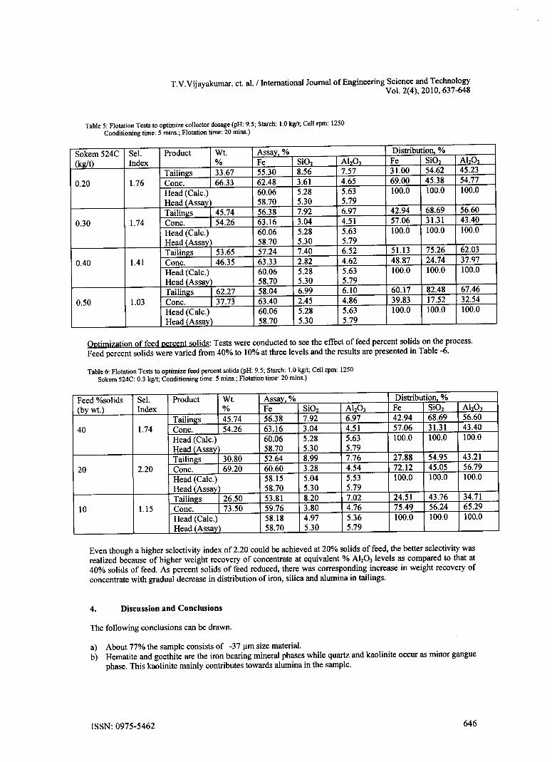
Table 5: Flotation Tests to optimize collector dosage (pH: 9.5; Starch: 1.0 kg/t; Cell rpm: 1250Conditioning time: 5 mins.; Flotation time: 20 mins.)
Sokem 524C Sel. Product Wt. Assay. % Distribution, %(kg/t) Index % Fe Si02 AhO) Fe Si02 AbO)
Tailings 33.67 55.30 8.56 7.57 31.00 54.62 45.230.20 1.76 Cone. 66.33 62.48 3.61 4.65 69.00 45.38 54.77
Head (Calc.) 60.06 5.28 5.63 100.0 100.0 100.0Head (Assay 58.70 5.30 5.79Tailings 45.74 56.38 7.92 6.97 42.94 68.69 56.60
0.30 1.74 Cone. 54.26 63.16 3.04 4.51 57.06 31.31 43.40Head (Calc.) 60.06 5.28 5.63 100.0 100.0 100.0Head (Assay) 58.70 5.30 5.79Tailings 53.65 57.24 7.40 6.52 51.13 75.26 62.03
0.40 1.41 Cone. 46.35 63.33 2.82 4.62 48.87 24.74 37.97Head (Calc.) 60.06 5.28 5.63 100.0 100.0 100.0Head (Assay 58.70 5.30 5.79Tailings 62.27 58.04 6.99 6.10 60.17 82.48 67.46
0.50 1.03 Cone. 37.73 63.40 2.45 4.86 39.83 17.52 32.54Head (Calc.) 60.06 5.28 5.63 100.0 100.0 100.0Head (Assav) 58.70 5.30 5.79
Optimization of feed percent solids: Tests were conducted to see the effect of feed percent solids on the process.Feed percent solids were varied from 40% to 10% at three levels and the results are presented in Table -6.
Table 6: Flotation Tests to optimize feed percent solids (pH: 9.5; Starch: 1.0 kg/t; Cell rpm: 1250Sokem 524C: 0.3 kg/t; Conditioning time: 5 mins.; Flotation time: 20 mins.)
Feed %solids Sel. Product Wt. Assav. % Distribution, %(by wt.) Index % Fe Si02 AhO) Fe SiOz AhO)
Tailings 45.74 56.38 7.92 6.97 42.94 68.69 56.6040 1.74 Cone. 54.26 63.16 3.04 4.51 57.06 31.31 43.40
Head (Calc.) 60.06 5.28 5.63 100.0 100.0 100.0Head (Assay 58.70 5.30 5.79Tailings 30.80 52.64 8.99 7.76 27.88 54.95 43.21
20 2.20 Cone. 69.20 60.60 3.28 4.54 72.12 45.05 56.79Head (Calc.) 58.15 5.04 5.53 100.0 100.0 100.0Head (Assay) 58.70 5.30 5.79Tailings 126.50 53.81 8.20 7.02 24.51 43.76 34.71
10 1.15 Cone. 173.50 59.76 3.80 4.76 75.49 56.24 65.29Head (Calc.) 58.18 4.97 5.36 100.0 100.0 100.0Head (Assay) 58.70 5.30 5.79
Even though a higher selectivity index of 2.20 could be achieved at 20% solids of feed, the better selectivity wasrealized because of higher weight recovery of concentrate at equivalent % AhO) levels as compared to that at40% solids of feed. As percent solids of feed reduced, there was corresponding increase in weight recovery ofconcentrate with gradual decrease in distribution of iron, silica and alumina in tailings.
a) About 77% the sample consists of -37 11msize material.b) Hematite and goethite are the iron bearing mineral phases while quartz and kaolinite occur as minor gangue
phase. This kaolinite mainly contributes towards alumina in the sample.

T.V.Vijayakumar. et. al. / International Journal of Engineering Science and TechnologyVol. 2(4), 2010, 637-648
c) Out of the three cationic colIectors studied Sokem 524C was proved to be the best among alI and was usedfurther to optimize other process parameters. An increase in the iron content of the concentrate is obtainedwith reduction in the Si02 and Aha].
d) The cationic flotation is attractive because these colIectors are insensitive towards hard water as welI as theinduction time is less and contact angles are high. However, concentrates with better recoveries can beobtained by column flotation. Among various flotation techniques, column flotation has shown to bepromising in obtaining high grade concentrates with less circuit complexity and lower power consumption(Bhaskar Raju et al., 1993, Prabhakar et aI., 1994; Bhaskar Raju and Prabhakar, 2000 and Vijaya Kumar etaI., 2005). In many cases, it was proved that the concentrates produced in a three-stage operation byconventional flotation could be achieved in a single-stage operation by using flotation column (Acharya etaI., 1995 and 1996; Prabhakar and Bhaskar Raju, 1998). Hence, based on this data, column flotation studieswere planned as part of future studies.
Acknowledgements: The authors are thankful to the Director, National MetalIurgical Laboratory, Jamshedpurfor his valuable guidance, encouragement and permission to publish this work. The authors would like to thankthe management of Joda East Iron Mines (JEIM), Keonjhar district of MIs TAT A Steel limited for providinglogistic support as welI as chemical analysis ofthe samples.
References[I] Acharya, B.c.. Rae. D.S.• Reddy, P.S.R. (1995) Mineralogical and beneficiation characteristics of low grade graphite ores. Powder
Handling and Processing, Vo1.7,No.3, pp:233-237.[2] Bhaskar Raju, G., Prabhakar, S and Sankaran, C. (1993) Beneficiation of iron ores by column flotation. Trans. Ins. Min. Met .• Sec. C.
pp.132-135.[3] Bhaskar Rl\ju, G and Prabhakar, S. (2000) Beneficiation of fluorspar by column flotation. Minerals & Metallurgical Processing.
VoU7. No.3. pp.167-172.[4] Das. B.• Prakash, S., Mohapatra, B.K.. Bhaumik, S.K. and Narashimhan. K.S. (1994) Beneficiation of iron ore slimes using
hydrocyclone. Minerals and Metallurgical Processing. v.9, No.2. pp.101-103.[5] Douglas. E. (1962) Derivation of a Basic Efficiency Formula for Concentrating Operations. IMM Transactions. Section C. v. 6.
pp.697-704.[6] Leja. J. (1983) Flotation surfactants. In Leja., J. Surface chemistry of froth flotation. 2"" printing, New York and London, Plenum
Press. Chapter 5. pp.205-339.[7] Pankratov. P. I. and Skorodumova, L. P. (1970) Flotation efficiency of different iron ore size classes. Jour. Mining Sci .• V.6. No.2,
pp.95-98.[8] Pradip (1994) Beneficiation of Indian iron ore slimes. Minerals & Metallurgical Processing. v.6. No.3, pp.179-194.[9] Prabhakar, S.• Bhaskar Raju, G and Sankaran. C. (1994) Quality improvement of copper concentrates by column flotation. Trans. Ind.
Inst. Metal .•• Vo1.47.pp.89-101.[!O] Prabhakar. S and Bhaskar Raju. G. (1998) Amenability of column flotation for lead zinc beneficiation. Metal .• Material .• and
Proce .•.•e.•• Vol.lO.pp.I09-I17.[11] Prasad, N.•Ponomarev. M.A. Mukheljee. S.K., Sengupta, P.K.•Roy. P.K. and Gupta, S.K. (1988) Introduction of new technologies for
beneficiation Indian hematite ores. reduction of looses and increase in their quality. In XVI Internalional Mineral Proce .•.•ingCongre .•.••(E.Forssberg, Ed.) pp.1369-1380.
[12] Roy. S.• and Das, A. (2008) Characterization and processing of low-grade iron ore slime from the Jilling area of India MineralProces .•ing and Extractive Metallurgy Rev., v.29, pp.213-23I. ,
[13] Vijaya Kumar. T.V.• Rae. D.S.• Rao. S.S.• Prabhakar. S.• Bhaskar Raju, G. & More. P.(2OO5)Semi-commercial scale studies usingflotation column and dual extraction column on iron ores of Goa, India .Jour. Min. & Mat. Chao & Eng., VolA. No.2, pp.I13-124.
Biographical notes about the authors
Tadiparthi Venkata Vijaya Kumar (T.V.VijayaKumar) is a scientist at National MetalIurgical LaboratoryMadras Centre, Chennai. He did his B.Sc. and M.A.Sc. (Mineral Processing) from Gulbarga University and laterobtained his M.Sc. (Engg.) from Indian Institute of Science, Bangalore. He worked as Junior Officer in NMDCR&D Centre, Hyderabad as Ore-dressing engineer and Deputy Manager at Rajpura-Dariba Mines of HindustanZinc Limited. He was recipient of two lIME awards for the best paper published and Altekar award by NML fortechnology transfer (2005). His research interests include basic and applied aspects related to conventional andcolumn flotation to low grade ores. Email: Tvvk6Yd.yahoo.com
Danda Srinivas Rao (D. S. Roo) is a Scientist-Ell at Institute of Minerals and Materials Technology. He passedout M.Sc. in Geology in 1986 from Berhampur University with two gold medals. He did his Ph.D. at thisInstitute and was awarded from Utkal University. He was a FelIow Scientist in this institute before joiningNational Metallurgical Laboratory (NML), Jamshedpur (1997-2007). He is engaged in characterisation andbeneficiation studies of ores and published more than 50 research papers. He was awarded Nijhawan andAltekar award (from NML); Peravadhanulu and Mishra award (from lIME) and Sankarsan Jena Memorialaward (from IE, India) for his publications. Email: mnJdsrfii.vahoo.co. in
Sripada Subba Roo (S.Subba Roo), PhD in Chemical Engineering from University of Newcastle, Australiaworking as Scientist-F at National Metallurgical Laboratory-Madras Centre, Chennai, India. He specializes in

T.V.Vijayakumar. et. al. / International Journal of Engineering Science and TechnologyVol. 2(4), 2010, 637-648
fine particle processing and also has interest in quality management systems. Dr. Roo has 25 papers to his creditpublished in various international and national journals. Email: sripadasi(j;.gmail.com
Swama Prabhakar (S.Prabhakar), Ph.D. in Ch~mistry and is presently working as Scientist-G at NationalMetallurgical Laboratory-Madras Centre, Chenna~ India. He has 25 years of research experience in the field ofMineral Processing, column flotation and surface properties of particles. He has published about 50 technicalpapers in reputed international and national journals. Dr. Prabhakar is a recipient of National Mineral Awardfrom Ministry of Mines, Govt. of India. Email: .~wImrghlU!.@Y1!JJQQ,~Qm
Guntamadugu Bhaskar Raju (G.Bhaskar Raju), Ph.D. in Chemistry and is Scientist-In-Charge at NationalMetallurgical Laboratory-Madras Centre, Chennai, India He has 25 years of research experience in the field ofMineral Processing and surface Chemistry. To his credit he has got 75 papers in various International, Nationaljournals and Seminar Proceedings. Dr.Raju is a recipient of National Mineral Award from Ministry of Mines,Govt. ofIndia. Email: gbruju55iiiihotmail.com