rev. a april 2021
TRANSCRIPT

M-18-16REV. AAPRIL 2021
© MAXON Lift Corp. 2021


LIFTGATE WARRANTY Type of Warranty: Full Parts and Labor
Term of Warranty: Standard Liftgates - 2 years from ship date or 6,000 cycles Premium Liftgates - 2 years from ship date or 10,000 cycles
This warranty shall not apply unless the product is installed, operated and maintained in accordance with MAXON Lift’s specifi cations as set forth in MAXON Lift’s Installation, Operation and Maintenance manuals. This warranty does not cover normal wear, maintenance or adjustments, damage or malfunction caused by improper handling, installation, abuse, misuse, negligence, or carelessness of operation. In addition, this warranty does not cover equipment that has had unauthorized modifi cations or alterations made to the product.
MAXON agrees to replace any components which are found to be defective during the fi rst 2 years of service, and will reimburse for labor based on MAXON’s Liftgate Warranty Flat Rate Schedule. (Copy of the Flat Rate is available at www.maxonlift.com.)
All warranty repairs must be performed by an authorized MAXON warranty facility. For any repairs that may exceed $500, including parts and labor, MAXON’s Technical Service Department must be notifi ed and an “Authorization Number” obtained. All claims for warranty must be received within 30 Days of the repair date, and include the following information:
1. Liftgate Model Number and Serial Number 2. The End User must be referenced on the claim 3. Detailed Description of Problem 4. Corrective Action Taken, and Date of Repair 5. Parts used for Repair, Including MAXON Part Number(s) 6. MAXON R.M.A. # and/or Authorization # if applicable (see below) 7. Person contacted at MAXON if applicable 8. Claim must show detailed information i.e. Labor rate and hours of work performed
Warranty claims can also be placed online at www.maxonlift.com. Online claims will be given priority processing. All claims for warranty will be denied if paperwork has not been received or claim submitted via Maxon website for processing by MAXON’s Warranty Department within 30 days of repair date.
All components may be subject to return for inspection, prior to the claim being processed. MAXON products may not be returned without prior written approval from MAXON’s Technical Service Department. Returns must be accompanied by a copy of the original invoice or reference with original invoice number and are subject to a credit deduction to cover handling charges and any necessary reconditioning costs. Unauthorized returns will be refused and will become the responsibility of the returnee.
Any goods being returned to MAXON Lift must be pre-approved for return, and have the R.M.A. number written on the outside of the package in plain view, and returned freight prepaid. All returns are subject to a 15% handling charge if not accompanied by a detailed packing list. Returned parts are subject to no credit and returned back to the customer. Defective parts requested for return must be returned within 30 days of the claim date for consideration to:
MAXON Lift Corp.10321 Greenleaf Ave., Santa Fe Springs, CA 90670
Attn: RMA#__
MAXON’s warranty policy does not include the reimbursement for travel time, towing, vehicle rental, service calls, oil, batteries or loss of income due to downtime. Fabrication or use of non Maxon parts, which are available from MAXON, are also not covered.
MAXON’s Flat Rate Labor Schedule takes into consideration the time required for diagnosis of a problem.
All Liftgates returned are subject to inspection and a 15% restocking fee. Any returned Liftgates or components that have been installed or not returned in new condition will be subject to an additional reworking charge, which will be based upon the labor and material cost required to return the Liftgate or component to new condition.
PURCHASE PART WARRANTY Term of Warranty: 1 Year from Date of Purchase. Type of Warranty: Part replacement only. MAXON will guarantee all returned genuine MAXON replacement parts upon receipt and inspection of parts and original invoice.
LIFT CORP.
11921 Slauson Ave.Santa Fe Springs, CA. 90670
CUSTOMER SERVICE: TELEPHONE (562) 464-0099 TOLL FREE (800) 227-4116
FAX: (888) 771-7713
WARRANTY/ RMA POLICY & PROCEDURE
NOTE: For latest version of all Manuals (and replacements), download theManuals from Maxon’s website at www.maxonlift.com.
All warranty replacements parts will be sent out via ground freight. If a rush shipment is requested, all freight charges will be billed to the requesting party.
TABLE OF CONTENTS
SUMMARY OF CHANGES: M-18-16 REV A ........................................................................ 6
WARNINGS ........................................................................................................................... 8
SAFETY INSTRUCTIONS .................................................................................................... 9
LIFTGATE TERMINOLOGY ................................................................................................ 10
PERIODIC MAINTENANCE ................................................................................................ 11
PERIODIC MAINTENANCE CHECKS .................................................................................11
PERIODIC MAINTENANCE CHECKLIST ........................................................................... 14
CHECKING HYDRAULIC FLUID ........................................................................................ 16
CHANGING HYDRAULIC FLUID ........................................................................................ 18
PLATFORM TORSION SPRING ADJUSTMENT ................................................................ 21
REPLACING PLATFORM TORSION SPRING ................................................................... 26
DECALS .............................................................................................................................. 28
DECALS & PLATES ........................................................................................................... 29
NONSKID & SAFETY STRIPING ....................................................................................... 30
SYSTEM DIAGRAMS ......................................................................................................... 32
PUMP & MOTOR SOLENOID OPERATION (GRAVITY DOWN) ........................................ 32
PUMP & MOTOR SOLENOID OPERATION (POWER DOWN) .......................................... 33
HYDRAULIC SCHEMATIC (GRAVITY DOWN) ................................................................... 34
HYDRAULIC SCHEMATIC (POWER DOWN) .................................................................... 35
ELECTRICAL SCHEMATIC (GRAVITY DOWN) ................................................................. 36
ELECTRICAL SCHEMATIC (POWER DOWN) ................................................................... 37
GPTLR ELECTRICAL VALUES & TORQUE SPECIFICATIONS ........................................ 38
BOLT TORQUES ................................................................................................................ 39
TROUBLESHOOTING ........................................................................................................ 40
MOTOR WILL NOT RUN ..................................................................................................... 40
PLATFORM WILL NOT RAISE, BUT MOTOR RUNS ......................................................... 41
PLATFORM RAISES BUT LEAKS DOWN .......................................................................... 42
PLATFORM RAISES PARTIALLY AND STOPS .................................................................. 44
LIFTGATE WILL NOT LIFT RATED CAPACITY .................................................................. 47
PLATFORM WILL NOT LOWER, LOWERS TOO SLOWLY, OR TOO QUICKLY ............... 50
RELIEF VALVE PRESSURE ADJUSTMENT - GRAVITY DOWN ....................................... 52
RELIEF VALVE PRESSURE ADJUSTMENT - POWER DOWN ......................................... 53
CHECKING THE POWER DOWN MODULE ...................................................................... 54

SUMMARY OF CHANGES: M-18-16 REV A
PAGE DESCRIPTION OF CHANGE
Cover Updated REV. and date of release.
6 Added SUMMARY OF CHANGES table.
12 Added illustration showing platform with retention ramp and shackles not touching the ground.
16, 18, 20 Changed pump cover fasteners to knob-type. Torque value deleted (not required).
16, 20 Added instruction to apply anti-seize to threads of pump cover fasteners.
17 Updated hydraulic oil tables.
21 Corrected NOTE about ground clearance of properly adjusted platform.
34, 35 Corrected fl ow control valve rate to 4 GPM, and relief valve 1 pressure setting to 2950 PSI on hydraulic schematics.
36, 37 Added 24 VDC battery callout to electrical schematics.
38 Updated Electrical Values for solenoid valves A, S1, and S2 and added Digital Cycle Counter.
40, 44, 46, 47, 49, 50, 54 Added 24 VDC values to troubleshooting procedures.
41 Changed to 1 illustrations that shows reservoir, relief valve and cover details.
42 Added 2 initial steps and an illustration to check for leaks and ensure lock valve is not stuck.
47 Added power unit reservoir fl uid levels, with platform at ground level, for Power Down and Gravity Down units.
45, 46, 48, 49, 52, 53 Updated relief valve 1 pressure setting to 2950 PSI.
48 Updated relief valve adjustment procedure for power down units to show removal of lift-ing line and connection of pressure gauge.
54 Added troubleshooting procedures for Power Down Module.

THIS PAGE INTENTIONALLY LEFT BLANK
11921 Slauson Ave. Santa Fe Springs, C
A. 90670 (800) 227-4116 FA
X (888) 771-7713
8
• Do not stand, or allow obstructions, under the platform when lowering the Liftgate. Be sure your feet are clear of the Liftgate.
• Keep fi ngers, hands, arms, legs, and feet clear of moving Liftgate parts (and platform edges) when operating the Liftgate.
• Disconnect Liftgate power cable from battery before repairing or servicing Liftgate.
Comply with the following WARNINGS and SAFETY INSTRUCTIONS while maintaining Liftgates. See Operation Manual for operating safety requirements.
• If it is necessary to stand on the platform while maintaining the Liftgate, keep your feet and any objects clear of the inboard edge of the platform. Your feet or objects on the platform can become trapped between the platform and the Liftgate extension plate.
WARNING!
• Correctly stow platform when not in use. Extended platforms could create a hazard for people and vehicles passing by.
• Recommended practices for welding on steel parts are contained in the current AWS (American Welding Society) D1.1 Structural Welding Code - Steel. Damage to Liftgate and/or vehicle, and personal injury could result from welds that are done incorrectly.
• Recommended practices for welding on aluminum parts are contained in the current AWS (American Welding Society) D1.2 Structural Welding Code - Aluminum. Damage to Liftgate and/or vehicle, and personal injury could result from welds that are done incorrectly.
WARNINGS
• Recommended practices for welding galvanized steel are contained in the current AWS (Ameri-can Welding Society) D19.0 Welding Zinc-Coated Steel. Damage to Liftgate and/or vehicle, and
personal injury can result from welds that are done incorrectly.
Installing and maintaining a liftgate can expose you to chemicals, including lead, which are knowto the State of California to cause cancer and birth defects or other reproductive harm. To minimize exposure, install and maintain liftgate in a well-ventilated area and wear proper Per-sonal protective equipment (PPE). For more information go to www.P65Warnings.ca.gov.
WARNING!

1192
1 Sl
auso
n A
ve.
Sant
a Fe
Spr
ings
, CA
. 90
670
(80
0) 2
27-4
116
FA
X (
888)
771
-771
3
9
SAFETY INSTRUCTIONS
• Keep decals clean and legible. If decals are illegible or missing, replace them. Free replacement decals are available from Maxon Customer Service.
• Consider the safety and location of bystanders and location of nearby objects when operating the Liftgate. Stand to one side of the platform while operating the Liftgate.
• Wear appropriate safety equipment such as protective eyeglasses, faceshield and clothing while performing maintenance on the Liftgate and handling the battery. Debris from drilling and contact with battery acid may injure unprotected eyes and skin.
• Do not allow untrained persons to operate the Liftgate.
• Be careful working by an automotive type battery. Make sure the work area is well ventilated and there are no fl ames or sparks near the battery. Never lay objects on the battery that can short the terminals together. If battery acid gets in your eyes, immediately seek fi rst aid. If acid gets on your skin, immediately wash it off with soap and water.
• If an emergency situation arises (vehicle or Liftgate) while operating the Liftgate, release the con-trol switch to stop the Liftgate.
• Read and understand the instructions in this Maintenance Manual before performing mainte-nance on the Liftgate.
• Before operating the Liftgate, read and understand the operating instructions in Operation Manual.
• Comply with all WARNING and instruction decals attached to the Liftgate.
• A correctly installed Liftgate operates smoothly and reasonably quiet. The only noticeable noise during operation comes from the power unit while the platform is raised. Listen for scraping, grat-ing and binding noises and correct the problem before continuing to operate Liftgate.
• Use only Maxon Authorized Parts for replacement parts. Provide Liftgate model and serial num-ber information with your parts order. Order replacement parts from:
MAXON LIFT CORP. Customer Service 11921 Slauson Ave., Santa Fe Springs, CA 90670
Online: www.maxonlift.com Express Parts Ordering: Phone (800) 227-4116 ext. 4345 Email: Ask your Customer Service representative
SAFETY INSTRUCTIONS

11921 Slauson Ave. Santa Fe Springs, C
A. 90670 (800) 227-4116 FA
X (888) 771-7713
10
LIFTGATE TERMINOLOGY
LIFT ARM
CONTROL SWITCH
PARALLEL ARM
LIFTCYLINDER
EXTENSION PLATE
PUMP BOX
MAIN FRAME
PLATFORM OPENER
PLATFORM
FLIPOVER WITH FIXED RAMP
HYDRAULIC LOCK
SPRING-ASSIST TORSION BAR
PLATFORM SUPPORT
BOLT-ONMOUNTING
PLATE
1192
1 Sl
auso
n A
ve.
Sant
a Fe
Spr
ings
, CA
. 90
670
(80
0) 2
27-4
116
FA
X (
888)
771
-771
3
11
Check both platform torsion springs to make sure there is grease between the coils. If grease is not visible in the valley between each coil, apply spray-on white lithium grease.Unfold & fold platform. If platform feels heavy while starting to fold, do PLATFORM TOR-SION SPRING ADJUSTMENT in the PERIODIC MAINTENANCE section of this manual.
Damaged cylinder seals and contaminated hydraulic fl uid can result from paint-ing the polished portion of the cylinder rod. To prevent damage, protect the exposed polished portion of the cylinder rod while painting.
CAUTION
PERIODIC MAINTENANCEPERIODIC MAINTENANCE CHECKS
Never operate the Liftgate if parts are loose or missing.WARNING!
NOTE: Make sure vehicle is parked on level ground while performing the maintenance checks.
Quarterly or 1250 Cycles (whichever occurs fi rst)Check the hydraulic fl uid level in the pump reservoir. Refer to the CHECKING HYDRAU-LIC FLUID procedure in the PERIODIC MAINTENANCE section. If hydraulic fl uid appears contaminated, refer to the CHANGING HYDRAULIC FLUID procedure in the PERIODIC MAINTENANCE section. Keep track of the grade of hydraulic fl uid in the pump reservoir. Never mix two different grades of fl uid.Check all hoses and fi ttings for chafi ng and fl uid leaks. Make sure hydraulic lock is in place and undamaged. Replace if necessary.Check electrical wiring for chafi ng and make sure wiring connections are tight and free of corrosion.Check that all WARNING and instruction decals, nonskid stickers, and safety striping are in place. Also, make sure decals are legible and decals, nonskid, and safety striping are clean and undamaged.Check that all roll pins are in place and protrude evenly from both sides of hinge pin collar. Replace roll pins if necessary.
Check for rust and oily surfaces on Liftgate. If there is rust or oil on Liftgate, clean it off. If bare metal is exposed on galvanized portions of the Liftgate, touch up the galvanized fi nish. To maintain original galvanized fi nish, MAXON recommends cold galvanize spray.
Semi-annually or 2500 Cycles (whichever occurs fi rst) Visually check the platform hinge pins for excessive wear and broken welds. See PARTS BREAKDOWN section for replacement parts. Also, do the Quarterly or 1250 Cycles maintenance checks.
Pump EP chassis grease in each lube fi tting on the cylinders and arms until grease starts oozing from ends of the bearings. The lubrication diagram on the PERIODIC MAINTE-NANCE CHECKLIST SHEET shows where to fi nd the lube fi ttings. Wipe off excess grease with a clean lint-free cloth.

11921 Slauson Ave. Santa Fe Springs, C
A. 90670 (800) 227-4116 FA
X (888) 771-7713
12
Check the platform and fl ipover as follows. Unfold the platform and fl ipover. Raise the platform to vehicle bed height and then lower it to the ground. Check if the shackles and tip of fl ipover touch the ground at the same time (FIG. 12-1). With the shackles touching, tip of a ramp-style fl ipover may be no more than 1/4” above the ground. A fl ipover equipped with retention ramp may have a maximum 2” of ground clearance at the tip of the fl ipover.
Visually check the entire Liftgate for excessively worn parts and broken welds, especially hinge pins. See PARTS BREAKDOWN section for replacement parts.
Annually or 5000 Cycles (whichever occurs fi rst)
LIFT ARMPARALLEL
ARM
LIFTCYLINDER
PLATFORM
PIVOT POINTS(PINS & BEARINGS)
PIVOT POINTS TO CHECKFIG. 12-3
Also, for aluminum fl ipovers equipped with single re-tention ramp and for steel fl ipovers, ensure latch is in place, undamaged, and working correctly. See PARTS BREAKDOWN sec-tion for replacement parts.
If the shackles are 1” or more above the ground when the tip of the fl ipover is touching the ground (FIG. 12-2), perform the ADJUST PLATFORM pro-cedure in the Installation Manual (M-18-14). If the adjustment does not correct the problem, check pins and bearings at the pivot points on both sides of the Liftgate (see FIG. 12-3).
SHACKLES NOT TOUCHING THE GROUND
FIG. 12-2
PERIODIC MAINTENANCE CHECKS - ContinuedPERIODIC MAINTENANCE
PLATFORM & SHACKLES TOUCH GROUND
FIG. 12-1
TIP OF FLIPOVER1/4”(MAX.)
1” (OR MORE)
SHACKLE
RETENTION RAMP
TIP OF FLIPOVER

1192
1 Sl
auso
n A
ve.
Sant
a Fe
Spr
ings
, CA
. 90
670
(80
0) 2
27-4
116
FA
X (
888)
771
-771
3
13
Also, do the Semi-annual or 2500 Cycles and Quarterly or 1250 Cycles checks.
To prevent unnecessary wear on parallel arms, check for worn thrust bearings as follows. Po-sition the platform 1”-2” above ground (FIG. 13-1). Push against the shackle (Item 1, FIG. 13-1A) and measure clearance (Item 1, FIG. 13-1A). Then, push against other side of shackle (Item 2, FIG. 13-1A) and measure clear-ance (Item 2, FIG. 13-1A). Re-peat for LH side shackle. If clear-ance is less than 0.050”, replace thrust bearing. See PARTS BREAKDOWN section for re-placement parts.
PLATFORM ABOVE GROUND LEVEL FIG. 13-1
CHECKING SHACKLECLEARANCES (RH SIDE SHOWN)
FIG. 13-1A
0.050”(MIN.)
0.050”(MIN.)
PARALLEL ARM
SHACKLE
THRUST BEARINGS
1”- 2”

11921 Slauson Ave. Santa Fe Springs, C
A. 90670 (800) 227-4116 FA
X (888) 771-7713
14
PERIODIC MAINTENANCE CHECKLIST
Quarterly or 1250 Cycles (whichever occurs fi rst)
Semi-annually or 2500 Cycles (whichever occurs fi rst)
Annually or 5000 Cycles (whichever occurs fi rst)
NOTE: Make sure vehicle is parked on level ground while performing maintenance checks.
Visually check the entire Liftgate for excessively worn parts and broken welds, espe-cially hinge pins.
Visually check platform & fl ipover. (See the PERIODIC MAINTENANCE CHECKS topic for more information.)
Visually check the thrust bearings on the shackles.
Do the Semi-annual or 2500 Cycles Checks on this checklist.
Do the Quarterly or 1250 Cycles Checks on this checklist.
Visually check the platform hinge pins for excessive wear and broken welds.
Do the Quarterly or 1250 Cycles Checks on this checklist.
Check the level and condition of the hydraulic fl uid.
Visually check all hoses and fi ttings for chafi ng and fl uid leaks, and check hydraulic lock.
Check electrical wiring for chafi ng and make sure wiring connections are tight and free of corrosion.
For more details pertaining to this checklist, see the PERIODIC MAINTENANCE CHECKS section in this Maintenance Manual.
Check that all WARNING and instruction decals, nonskid stickers, and safety strip-ing are in place. Also, make sure decals are legible and decals, nonskid, and safety striping are clean and undamaged.
Check that all roll pins are in place and protrude evenly from both sides of hinge pin col-lar. Replace roll pins if necessary.
Check for rust and oily surfaces on Liftgate. If there is rust or oil on Liftgate or if the Lift-gate is dirty, clean it off. Touch up the galvanized fi nish where bare metal is showing.
Check both platform torsion springs to make sure there is grease in the valley between each coil. If grease is not visible, apply spray-on white lithium grease to the valley be-tween each coil. Unfold & fold platform. If platform feels heavy while starting to fold, do PLATFORM TORSION SPRING ADJUSTMENT in the PERIODIC MAINTENANCE section of this manual.Pump EP chassis grease in each lube fi tting on the cylinders and arms until grease starts oozing from ends of the bearings. Refer to lubrication diagram on the next page. Wipe off excess grease with a clean lint-free cloth.
PERIODIC MAINTENANCE
1192
1 Sl
auso
n A
ve.
Sant
a Fe
Spr
ings
, CA
. 90
670
(80
0) 2
27-4
116
FA
X (
888)
771
-771
3
15
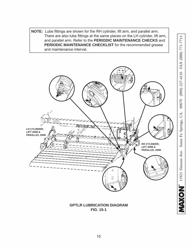
GPTLR LUBRICATION DIAGRAMFIG. 15-1
NOTE: Lube fi ttings are shown for the RH cylinder, lift arm, and parallel arm. There are also lube fi ttings at the same places on the LH cylinder, lift arm, and parallel arm. Refer to the PERIODIC MAINTENANCE CHECKS and PERIODIC MAINTENANCE CHECKLIST for the recommended grease and maintenance interval.
RH CYLINDER, LIFT ARM & PARALLEL ARM
LH CYLINDER, LIFT ARM & PARALLEL ARM
11921 Slauson Ave. Santa Fe Springs, C
A. 90670 (800) 227-4116 FA
X (888) 771-7713
16
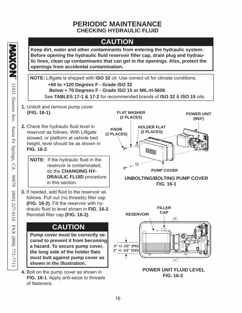
CAUTIONPump cover must be correctly se-cured to prevent it from becoming a hazard. To secure pump cover, the long side of the holder fl ats must butt against pump cover as shown in the illustration.
1. Unbolt and remove pump cover (FIG. 16-1).
CHECKING HYDRAULIC FLUID
3. If needed, add fl uid to the reservoir as follows. Pull out (no threads) fi ller cap (FIG. 16-2). Fill the reservoir with hy-draulic fl uid to level shown in FIG. 16-2. Reinstall fi ller cap (FIG. 16-2).
4. Bolt on the pump cover as shown in FIG. 16-1. Apply anti-seize to threads
of fasteners.
2. Check the hydraulic fl uid level in reservoir as follows. With Liftgate stowed, or platform at vehicle bed height, level should be as shown in FIG. 16-2.
NOTE: If the hydraulic fl uid in the reservoir is contaminated,
do the CHANGING HY-DRAULIC FLUID procedure in this section.
PERIODIC MAINTENANCE
CAUTIONKeep dirt, water and other contaminants from entering the hydraulic system. Before opening the hydraulic fl uid reservoir fi ller cap, drain plug and hydrau-lic lines, clean up contaminants that can get in the openings. Also, protect the openings from accidental contamination.
NOTE: Liftgate is shipped with ISO 32 oil. Use correct oil for climate conditions. +50 to +120 Degrees F - Grade ISO 32 Below + 70 Degrees F - Grade ISO 15 or MIL-H-5606
See TABLES 17-1 & 17-2 for recommended brands of ISO 32 & ISO 15 oils.
POWER UNIT FLUID LEVELFIG. 16-2
FILLER CAPRESERVOIR
3” +/- 1/2” (PD) 2” +/- 1/2” (GD)
UNBOLTING/BOLTING PUMP COVERFIG. 16-1
FLAT WASHER(2 PLACES)
HOLDER FLAT(2 PLACES)
PUMP COVER
POWER UNIT(REF)
KNOB(2 PLACES)
1192
1 Sl
auso
n A
ve.
Sant
a Fe
Spr
ings
, CA
. 90
670
(80
0) 2
27-4
116
FA
X (
888)
771
-771
3
17
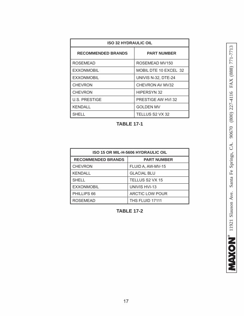
TABLE 17-2
TABLE 17-1
ISO 32 HYDRAULIC OIL
RECOMMENDED BRANDS PART NUMBER
ROSEMEAD ROSEMEAD MV150
EXXONMOBIL MOBIL DTE 10 EXCEL 32
EXXONMOBIL UNIVIS N-32, DTE-24
CHEVRON CHEVRON AV MV32
CHEVRON HIPERSYN 32
U.S. PRESTIGE PRESTIGE AW HVI 32
KENDALL GOLDEN MV
SHELL TELLUS S2 VX 32
ISO 15 OR MIL-H-5606 HYDRAULIC OIL
RECOMMENDED BRANDS PART NUMBERCHEVRON FLUID A, AW-MV-15
KENDALL GLACIAL BLU
SHELL TELLUS S2 VX 15
EXXONMOBIL UNIVIS HVI-13
PHILLIPS 66 ARCTIC LOW POUR
ROSEMEAD THS FLUID 17111

11921 Slauson Ave. Santa Fe Springs, C
A. 90670 (800) 227-4116 FA
X (888) 771-7713
18
1. Unbolt and remove pump cover (FIG. 18-1). Place empty 5 gal-lon bucket under drain plug (FIG. 18-2).
CHANGING HYDRAULIC FLUID
GRAVITY DOWN & POWER DOWN LIFTGATES
PERIODIC MAINTENANCE
CAUTIONKeep dirt, water and other contaminants from entering the hydraulic system. Before opening the hydraulic fl uid reservoir fi ller cap, drain plug and hydrau-lic lines, clean up contaminants that can get in the openings. Also, protect the openings from accidental contamination.
FIG. 18-2DRAIN PLUG
RESERVOIR
+50 to +120 Degrees F - Grade ISO 32 Below + 70 Degrees F - Grade ISO 15 or MIL-H-5606
NOTE: Liftgate is shipped with ISO 32 oil. Use correct oil for climate conditions.
See TABLES 17-1 & 17-2 for recommended brands of ISO 32 & ISO 15 OILS.
UNBOLTING PUMP COVERFIG. 18-1
FLAT WASHER(2 PLACES)
HOLDER FLAT(2 PLACES)
PUMP COVER
POWER UNIT(REF)
KNOB(2 PLACES)

1192
1 Sl
auso
n A
ve.
Sant
a Fe
Spr
ings
, CA
. 90
670
(80
0) 2
27-4
116
FA
X (
888)
771
-771
3
19
GRAVITY DOWN LIFTGATES1. Lower platform to ground. Pull out (no threads) drain plug (FIG. 19-1). Drain hydraulic fl uid from system. Reinstall drain plug.
GRAVITY DOWN PUMP & MOTORFIG. 19-1
2. Pull out (no threads) fi ller cap (FIG. 19-1) and refi ll reservoir with hydraulic fl uid to level shown in FIG. 19-1. Reinstall fi ller cap (FIG. 19-1).
3. Stow the Lift and do the CHECKING HY-DRAULIC FLUID procedure in this section of the manual.
2. Disconnect the white wire (FIG. 19-2) from starter solenoid. Lower the platform while draining the remaining hydraulic fl uid from sys- tem. Reinstall drain plug. Reconnect the white wire to starter solenoid.
1. Open and raise platform to vehicle bed height. Pull out (no threads) drain plug (FIG. 19-1). Drain hydraulic fl uid.
POWER DOWN LIFTGATES
3. Pull out (no threads) fi ller cap (FIG. 19-1) and refi ll reservoir with hydraulic fl uid to level shown in FIG. 19-1. Reinstall fi ller cap (FIG. 19-1).
4. Stow the Lift and do the CHECKING HYDRAULIC FLUID procedure in this section of the manual.
POWER DOWN PUMPFIG. 19-2
HEX NUTWHITE WIRE
STARTER SOLENOID
FILLER CAPRESERVOIR
DRAIN PLUG
3” +/- 1/2” (PD) 2” +/- 1/2” (GD)
11921 Slauson Ave. Santa Fe Springs, C
A. 90670 (800) 227-4116 FA
X (888) 771-7713
20
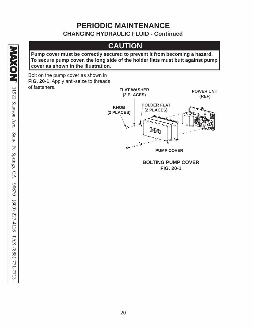
PERIODIC MAINTENANCE
Bolt on the pump cover as shown in FIG. 20-1. Apply anti-seize to threads
of fasteners.
BOLTING PUMP COVERFIG. 20-1
FLAT WASHER(2 PLACES)
HOLDER FLAT(2 PLACES)
PUMP COVER
POWER UNIT(REF)
KNOB(2 PLACES)
CAUTIONPump cover must be correctly secured to prevent it from becoming a hazard. To secure pump cover, the long side of the holder fl ats must butt against pump cover as shown in the illustration.
CHANGING HYDRAULIC FLUID - Continued

1192
1 Sl
auso
n A
ve.
Sant
a Fe
Spr
ings
, CA
. 90
670
(80
0) 2
27-4
116
FA
X (
888)
771
-771
3
21
PLATFORM TORSION SPRING ADJUSTMENT
1. Make sure vehicle is parked on level ground. LOWER the Liftgate to the ground and unfold platform only (FIG. 21-1).
NOTE: Perform the following adjustment if platform feels heavy as you start to fold it for stowing. If adjusted as follows, the torsion springs will reduce the amount of effort you need to start folding the platform.
UNFOLDING PLATFORMFIG. 21-1
2. Measure the distance between the bottom block of the platform and the
ground (FIG. 21-2).
PLATFORM 0-4” ABOVE GROUNDFIG. 21-2
PERIODIC MAINTENANCE
4” MAX
NOTE: A properly adjusted platform will stay in position with the bottom 4” or less above the ground while fl ipover is being folded. If distance is more than 4”, and platform can be folded and unfolded with ease, the greater distance is allowed and no adjustment is necessary. Acceptable force to fold the platform is 40 lb maximum.
11921 Slauson Ave. Santa Fe Springs, C
A. 90670 (800) 227-4116 FA
X (888) 771-7713
22
TORSION SPRING
PIN
CORRECTLY POSITIONED PLATFORM & FLIPOVER
FIG. 22-1A
“H”SUPPORT BLOCK
PIN LOCATIONFIG. 22-1
FREELEG
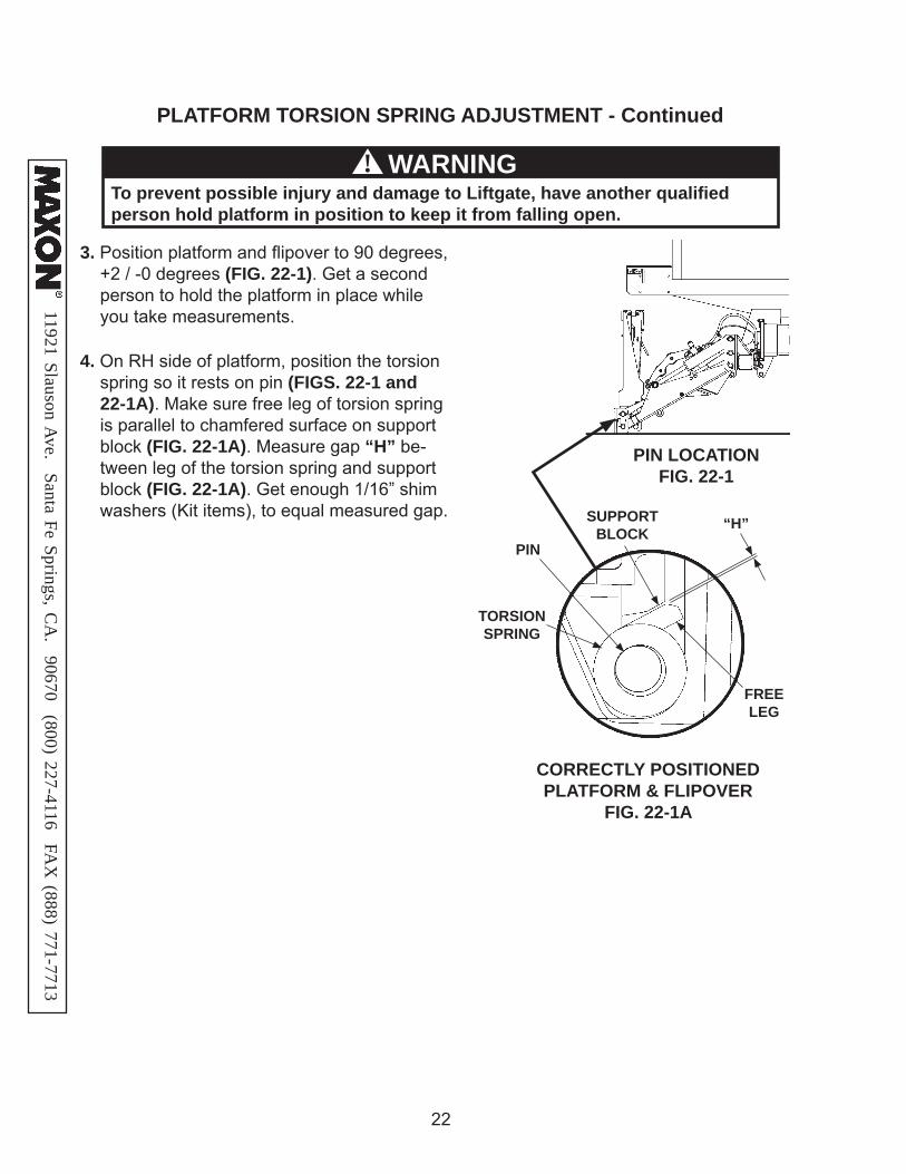
3. Position platform and fl ipover to 90 degrees, +2 / -0 degrees (FIG. 22-1). Get a second person to hold the platform in place while you take measurements.
4. On RH side of platform, position the torsion spring so it rests on pin (FIGS. 22-1 and 22-1A). Make sure free leg of torsion spring is parallel to chamfered surface on support block (FIG. 22-1A). Measure gap “H” be-tween leg of the torsion spring and support block (FIG. 22-1A). Get enough 1/16” shim washers (Kit items), to equal measured gap.
To prevent possible injury and damage to Liftgate, have another qualifi ed person hold platform in position to keep it from falling open.
WARNING!
PLATFORM TORSION SPRING ADJUSTMENT - Continued

1192
1 Sl
auso
n A
ve.
Sant
a Fe
Spr
ings
, CA
. 90
670
(80
0) 2
27-4
116
FA
X (
888)
771
-771
3
23
6. Repeat steps 2, 3, 4, and 5 for the LH torsion spring.
7. Repeat step 1 to check clearance of bottom of platform above the ground.
SHIM WASHERS
SHIMMING TORSION SPRINGFIG. 23-2
SHACKLE BRACKET
BOLT
FLAT WASHER
LOCK NUT
5. If necessary, adjust the torsion springs to lower the platform to 4” or less above the ground. Unbolt pin bracket (FIG. 23-1). Then, rotate the pin bracket away from the shackle bracket until the free leg of the torsion spring makes contact with the new block welded to the platform support. Then, using shim washers that equal the gap “H” measured in step 14, insert the shim washers between pin bracket and shackle bracket (FIGS. 24-1 and 23-2). Bolt shim washers in place be-tween pin bracket and shackle bracket (FIG. 24-2). Tighten bolt and lock nut.
ADJUST PLATFORMFIG. 23-1
SHACKLE
PIN
PIN BRACKET
PIN BRACKET
SHACKLE BRACKET
FLAT WASHER
BOLT
LOCK NUT
11921 Slauson Ave. Santa Fe Springs, C
A. 90670 (800) 227-4116 FA
X (888) 771-7713
24
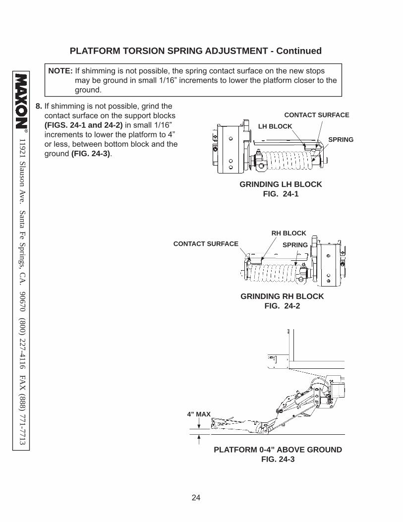
8. If shimming is not possible, grind the contact surface on the support blocks (FIGS. 24-1 and 24-2) in small 1/16” increments to lower the platform to 4” or less, between bottom block and the ground (FIG. 24-3).
NOTE: If shimming is not possible, the spring contact surface on the new stops may be ground in small 1/16” increments to lower the platform closer to the ground.
GRINDING RH BLOCKFIG. 24-2
CONTACT SURFACELH BLOCK
SPRING
SPRINGCONTACT SURFACERH BLOCK
GRINDING LH BLOCKFIG. 24-1
PLATFORM 0-4” ABOVE GROUNDFIG. 24-3
4” MAX
PLATFORM TORSION SPRING ADJUSTMENT - Continued
1192
1 Sl
auso
n A
ve.
Sant
a Fe
Spr
ings
, CA
. 90
670
(80
0) 2
27-4
116
FA
X (
888)
771
-771
3
25
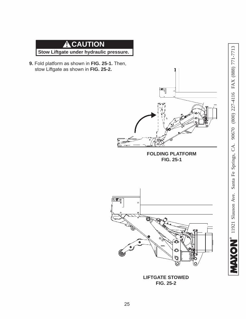
9. Fold platform as shown in FIG. 25-1. Then, stow Liftgate as shown in FIG. 25-2.
FOLDING PLATFORM FIG. 25-1
LIFTGATE STOWED FIG. 25-2
CAUTIONStow Liftgate under hydraulic pressure.
!
11921 Slauson Ave. Santa Fe Springs, C
A. 90670 (800) 227-4116 FA
X (888) 771-7713
26
REPLACING PLATFORM TORSION SPRING
FIG. 26-1
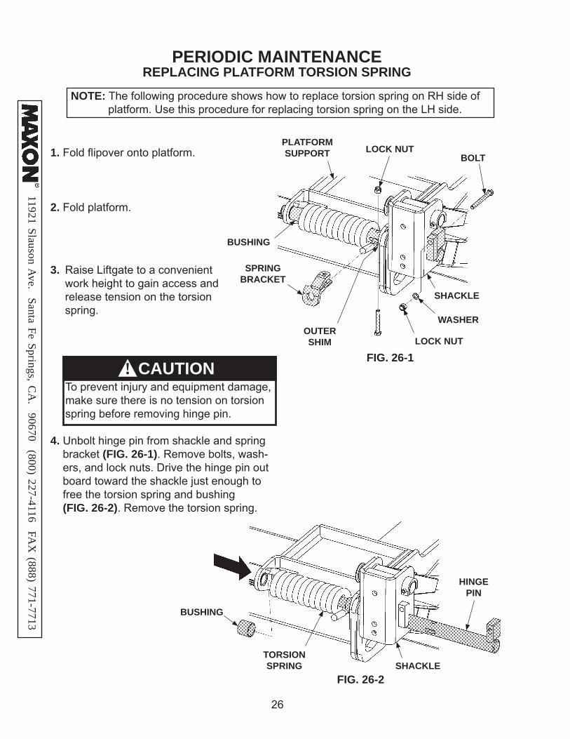
1. Fold fl ipover onto platform.
4. Unbolt hinge pin from shackle and spring bracket (FIG. 26-1). Remove bolts, wash- ers, and lock nuts. Drive the hinge pin out board toward the shackle just enough to free the torsion spring and bushing (FIG. 26-2). Remove the torsion spring.
3. Raise Liftgate to a convenient work height to gain access and release tension on the torsion spring.
2. Fold platform.
NOTE: The following procedure shows how to replace torsion spring on RH side of platform. Use this procedure for replacing torsion spring on the LH side.
FIG. 26-2
HINGE PIN
TORSION SPRING
BUSHING
SHACKLE
CAUTION!To prevent injury and equipment damage, make sure there is no tension on torsion spring before removing hinge pin.
PERIODIC MAINTENANCE
WASHER
LOCK NUT
LOCK NUTBOLT
PLATFORM SUPPORT
SPRING BRACKET
OUTER SHIM
SHACKLE
BUSHING

1192
1 Sl
auso
n A
ve.
Sant
a Fe
Spr
ings
, CA
. 90
670
(80
0) 2
27-4
116
FA
X (
888)
771
-771
3
27
OUTER SHIM
HINGE PIN
5. Install the new torsion spring and bushing as shown in FIG. 27-1. Make sure non-chamfered leg of the spring is inserted in the spring bracket (FIG. 27-1). Make sure chamfered leg of the spring is vis-ible and resting against the plat-form support (FIG. 27-1).
6. Drive the hinge pin into correct position through the platform support as shown in FIG. 27-1. Line up the bolt hole in the hinge pin with the hole in the shackle and spring bracket. Bolt the hinge pin to platform support and spring bracket with bolts, washers, lock nuts (FIG. 27-1). Torque the 3/8”-16 spring pin bolt and 3/8”-16 spring bracket bolt 35 to 52 lb-ft.
7. Do the PLATFORM TORSION SPRING ADJUSTMENT in this manual.
8. Operate the Liftgate according to instructions in Operation Manual to make sure it operates correctly.
FIG. 27-1
BOLT
BOLT
WASHER
LOCK NUT
LOCK NUT
PLATFORM SUPPORT
SPRING BRACKET
SHACKLE
NON-CHAMFERED LEG
CHAMFERED LEG
BUSHING

11921 Slauson Ave. Santa Fe Springs, C
A. 90670 (800) 227-4116 FA
X (888) 771-7713
28
DECALS
FIG. 28-1
STOW WARNING DECALP/N 282847-02
CAPACITY DECAL(SEE TABLE 28-1)
TABLE 28-1
INSTRUCTION DECALP/N 299361-01
DECAL SHEET(SMALL, WARNING & CAUTION)
P/N 282522-01
CAPACITY DECALSCAPACITY PART NO.2500 LBS. 2203823300 LBS. 220388-024400 LBS. 2531555500 LBS. 253161
NOTE: Ensure there is no residue, dirt or corrosion where decals are attached. If necessary, clean surface before attaching decals.
UP DECALP/N 299038-01
DOWN DECALP/N 299038-01

1192
1 Sl
auso
n A
ve.
Sant
a Fe
Spr
ings
, CA
. 90
670
(80
0) 2
27-4
116
FA
X (
888)
771
-771
3
29
DECALS & PLATES
FIG. 29-1
WARNING DECALP/N 265736-02
CAUTION DECAL(FLIPOVER EQUIPPED WITH LATCH ONLY)
P/N 267694-01
WARNING DECALP/N 265736-03
PARTS QR CODE DECAL
P/N 299348-08
SERIAL PLATE (REF)
MAXON 24/7SUPPORT DECAL
P/N 298634-01
MAXON PLATEP/N 280004-01
11921 Slauson Ave. Santa Fe Springs, C
A. 90670 (800) 227-4116 FA
X (888) 771-7713
30
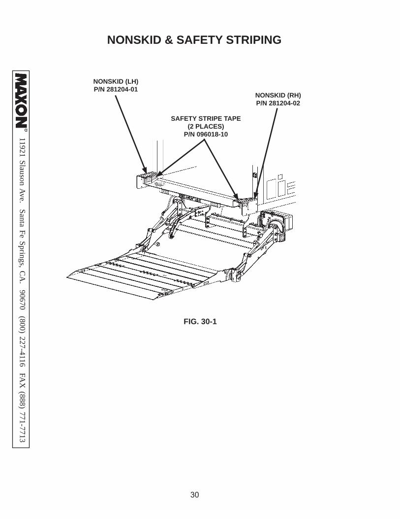
NONSKID & SAFETY STRIPING
SAFETY STRIPE TAPE (2 PLACES)
P/N 096018-10
NONSKID (LH)P/N 281204-01
NONSKID (RH)P/N 281204-02
FIG. 30-1

1192
1 Sl
auso
n A
ve.
Sant
a Fe
Spr
ings
, CA
. 90
670
(80
0) 2
27-4
116
FA
X (
888)
771
-771
3
31
THIS PAGE INTENTIONALLY LEFT BLANK
11921 Slauson Ave. Santa Fe Springs, C
A. 90670 (800) 227-4116 FA
X (888) 771-7713
32
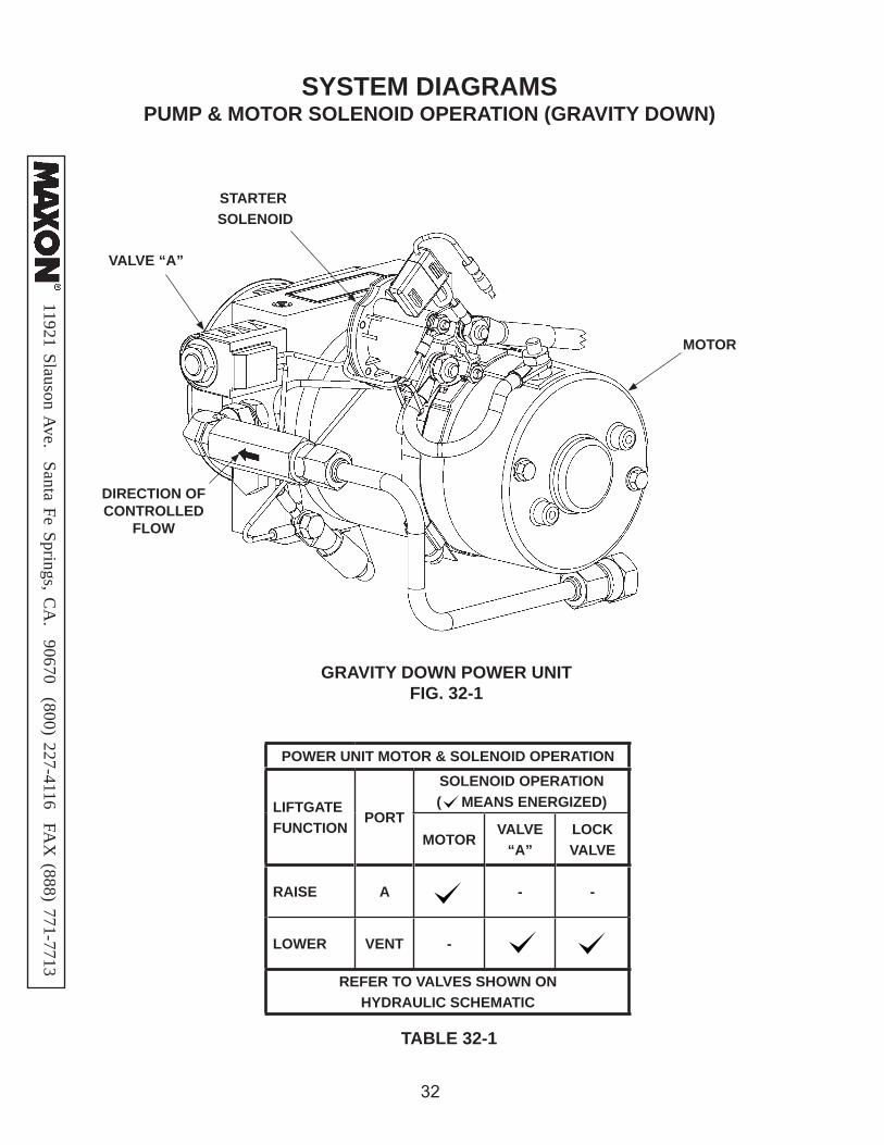
SYSTEM DIAGRAMS
GRAVITY DOWN POWER UNITFIG. 32-1
STARTER SOLENOID
VALVE “A”
MOTOR
PUMP & MOTOR SOLENOID OPERATION (GRAVITY DOWN)
TABLE 32-1
POWER UNIT MOTOR & SOLENOID OPERATION
LIFTGATE FUNCTION
PORT
SOLENOID OPERATION ( MEANS ENERGIZED)
MOTORVALVE
“A”LOCK VALVE
RAISE A - -
LOWER VENT -
REFER TO VALVES SHOWN ON HYDRAULIC SCHEMATIC
DIRECTION OF CONTROLLED
FLOW

1192
1 Sl
auso
n A
ve.
Sant
a Fe
Spr
ings
, CA
. 90
670
(80
0) 2
27-4
116
FA
X (
888)
771
-771
3
33
POWER DOWN POWER UNITFIG. 33-1
STARTER SOLENOID
VALVE “S1”
VALVE “S2”
MOTOR
PUMP & MOTOR SOLENOID OPERATION (POWER DOWN)
TABLE 33-1
POWER UNIT MOTOR & SOLENOID OPERATION
LIFTGATE FUNCTION
PORT
SOLENOID OPERATION ( MEANS ENERGIZED)
MOTORVALVE “S2”
VALVE “S1”
LOCKVALVE
RAISE A - -
LOWER B -
REFER TO VALVES SHOWN ON HYDRAULIC SCHEMATIC
DIRECTION OF CONTROLLED
FLOW

11921 Slauson Ave. Santa Fe Springs, C
A. 90670 (800) 227-4116 FA
X (888) 771-7713
34
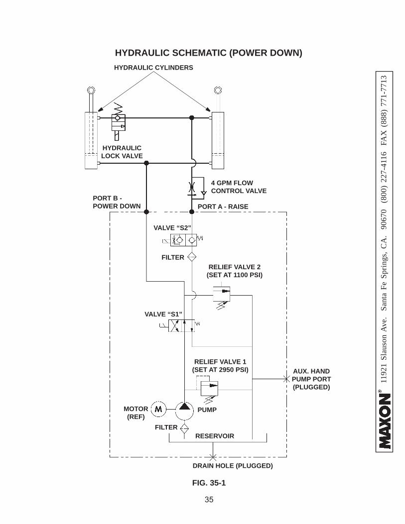
HYDRAULIC SCHEMATIC (GRAVITY DOWN)
FIG. 34-1
4 GPM FLOW CONTROL VALVE
VALVE A
RELIEF VALVE(SET AT 2950 PSI)
PUMP
MOTOR (REF)
RESERVOIR
CHECK VALVE
FILTER
DRAIN PORT (PLUGGED)
HYDRAULIC CYLINDERS
HYDRAULIC LOCK VALVE
VENTPORT
RETURN PORT (PLUGGED)
PORT A - RAISE
AUX. HANDPUMP PORT (PLUGGED)
GAUGE PORT (PLUGGED)
1192
1 Sl
auso
n A
ve.
Sant
a Fe
Spr
ings
, CA
. 90
670
(80
0) 2
27-4
116
FA
X (
888)
771
-771
3
35
FIG. 35-1
HYDRAULIC SCHEMATIC (POWER DOWN)HYDRAULIC CYLINDERS
PORT B - POWER DOWN PORT A - RAISE
RELIEF VALVE 2(SET AT 1100 PSI)
PUMP
AUX. HANDPUMP PORT (PLUGGED)
VALVE “S2”
RESERVOIR
DRAIN HOLE (PLUGGED)
FILTER
MOTOR(REF)
RELIEF VALVE 1(SET AT 2950 PSI)
HYDRAULIC LOCK VALVE
4 GPM FLOW CONTROL VALVE
FILTER
VALVE “S1”

11921 Slauson Ave. Santa Fe Springs, C
A. 90670 (800) 227-4116 FA
X (888) 771-7713
36
ELECTRICAL SCHEMATIC (GRAVITY DOWN)
FIG. 36-1
(DOWN)(UP)
CONTROL SWITCH
STARTERSOLENOID
MOTOR
FUSE HOLDER WITH 10 AMP
FUSE
JUNCTION BLOCK
WHITE
BLACKGREEN
1
1
2
2
CYCLE COUNTER
BATTERY(12V OR 24V)
VALVE “A”
LOCK VALVE
BLACK
RED
CABLE WITH 175 AMP FUSE

1192
1 Sl
auso
n A
ve.
Sant
a Fe
Spr
ings
, CA
. 90
670
(80
0) 2
27-4
116
FA
X (
888)
771
-771
3
37
ELECTRICAL SCHEMATIC (POWER DOWN)
FIG. 37-1
NOTE: One cycle is counted when the down switch is activated for 5-7 continuous seconds.

11921 Slauson Ave. Santa Fe Springs, C
A. 90670 (800) 227-4116 FA
X (888) 771-7713
38
TABLE 38-1
GPTLR ELECTRICAL VALUES & TORQUE SPECIFICATIONS
Solenoid Switch 12V 24V
Coil resistance: 5.4Ω @70ºF. ±15% 20.1Ω @70ºF. ±15%
Ampere: 2.2A 1.2A
Coil terminal torque: 10-15 lb-in max.
Contact terminal torque: 30-35 lb-in max.
Solenoid Valves (A, S1, & S2)
Coil resistance: 4Ω @ 70ºF. ±15% 26.7Ω @ 70ºF. ±15%
Ampere: 3A, 2.5A @10V
Coil terminal torque: 15-45 lb-in max.
Valve cartridge torque: 25-30 lb-ft max.
Coil nut torque: 15-45 lb-in
Solenoid Lock Valve
Coil resistance: 8Ω @ 70ºF. ±15% 30Ω @ 70ºF. ±15%
Ampere: 1.5A 0.8A
Coil nut torque: 3-4.5 lb-ft max.
Valve cartridge torque: 18.5-22 lb-ft max.
Digital Cycle Counter
Input voltage 4V - 30V 4V - 30V
Ampere <2mA
Ground Cable
Cap screw torque: 24 lb-ft max.

1192
1 Sl
auso
n A
ve.
Sant
a Fe
Spr
ings
, CA
. 90
670
(80
0) 2
27-4
116
FA
X (
888)
771
-771
3
39
BOLT TORQUES
TABLE 39-1
The torque values in the following table are provided for torquing grade 8 bolts on Liftgate mechanical parts. To prevent damage, never use the infor-mation in this table for torquing electrical or hydraulic hose connections on the pump assembly.
CAUTION

11921 Slauson Ave. Santa Fe Springs, C
A. 90670 (800) 227-4116 FA
X (888) 771-7713
40
TROUBLESHOOTINGMOTOR WILL NOT RUN
2. Touch a jumper wire to terminals “B” & “D” (FIG. 40-1). If motor runs, check control switch, the switch connections, and white wire. Check and correct wiring connections or replace the control switch.
3. Touch heavy jumper cables to terminals “A” & “B” (FIG. 40-1). a. If motor runs, replace the starter solenoid. b. If motor does not run, repair or replace the pump motor.
1. Connect voltmeter between starter solenoid terminal “B” and ground connection on pump (FIG. 40-1). Verify that full battery volt-age is at “B”. Recharge the bat-teries if voltmeter indicates less than 12.6 volts DC, or 25.2 volts DC for a 24 volt system.
GRAVITY DOWN POWER UNITFIG. 40-1
TERMINAL “A”LOAD
TERMINAL “B”BATTERY (+)
STARTER SOLENOID
TERMINAL “C”GROUND (-)
TERMINAL “D”SWITCHED
BATTERY (+)
GROUNDCONNECTION
1192
1 Sl
auso
n A
ve.
Sant
a Fe
Spr
ings
, CA
. 90
670
(80
0) 2
27-4
116
FA
X (
888)
771
-771
3
41
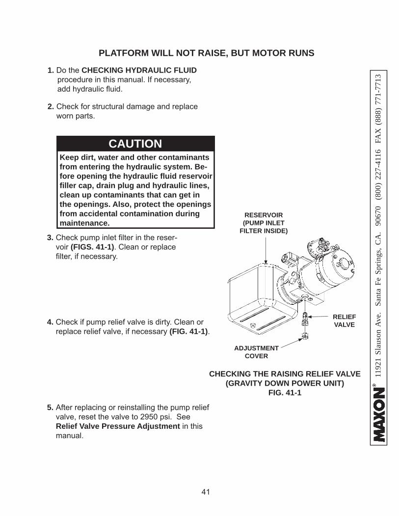
PLATFORM WILL NOT RAISE, BUT MOTOR RUNS
1. Do the CHECKING HYDRAULIC FLUID procedure in this manual. If necessary, add hydraulic fl uid.
2. Check for structural damage and replace worn parts.
3. Check pump inlet fi lter in the reser-voir (FIGS. 41-1). Clean or replace fi lter, if necessary.
Keep dirt, water and other contaminants from entering the hydraulic system. Be-fore opening the hydraulic fl uid reservoir fi ller cap, drain plug and hydraulic lines, clean up contaminants that can get in the openings. Also, protect the openings from accidental contamination during maintenance.
CAUTION
CHECKING THE RAISING RELIEF VALVE (GRAVITY DOWN POWER UNIT)
FIG. 41-1
ADJUSTMENT COVER
RELIEF VALVE4. Check if pump relief valve is dirty. Clean or
replace relief valve, if necessary (FIG. 41-1).
5. After replacing or reinstalling the pump relief valve, reset the valve to 2950 psi. See Relief Valve Pressure Adjustment in this manual.
RESERVOIR(PUMP INLET
FILTER INSIDE)
11921 Slauson Ave. Santa Fe Springs, C
A. 90670 (800) 227-4116 FA
X (888) 771-7713
42
TROUBLESHOOTING - ContinuedPLATFORM RAISES BUT LEAKS DOWN
3. Check if solenoid valve is constantly energized. Connect voltmeter negative (-) lead to ground (-) connection on pump and positive (+) lead to (+) ter-minal on valve “A” (FIG. 42-2). If voltmeter reads battery volt-age, check for faulty wiring or toggle switch.
GRAVITY DOWN POWER UNITFIG. 42-2
TERMINAL “A”LOAD
TERMINAL “B”BATTERY (+)
STARTER SOLENOID
VALVE “A” TERMINAL “C”
GROUND (-)
TERMINAL “D”SWITCHED
BATTERY (+)
1. Check for external leaks, leaking lines and fi ttings at the cylinders and pump assembly.
CHECKING HYDRAULIC LOCK VALVEFIG. 42-1
HYDRAULIC LOCK VALVE
RH CYLINDER
2. Check that hydraulic lock valve is not stuck in the open position
(FIG. 42-1).
GROUNDCONNECTION

1192
1 Sl
auso
n A
ve.
Sant
a Fe
Spr
ings
, CA
. 90
670
(80
0) 2
27-4
116
FA
X (
888)
771
-771
3
43
4. Make sure platform is on the ground. Re-move cartridge for solenoid valve “A” (FIGS. 43-1 and 43-2). Push on the plunger in the valve by inserting small screwdriver in the open end (FIG. 43-3). If the plunger does not move with a smooth, spring-loaded ac-tion (approximately 1/8”), replace the valve cartridge. Reinstall cartridge and coil for valve A. Torque valve cartridge to 25 - 30 lb-in and coil nut to 15 - 45 lb-in.
CHECKING SOLENOID VALVE FIG. 43-3
Keep dirt, water and other contaminants from entering the hydraulic system. Be-fore opening the hydraulic fl uid reservoir fi ller cap, drain plug and hydraulic lines, clean up contaminants that can get in the openings. Also, protect the openings from accidental contamination during maintenance.
CAUTION
REMOVING SOLENOID VALVE(GRAVITY DOWN POWER UNIT)
FIG. 43-1
VALVE CARTRIDGE
COIL
NUT
VALVE CARTRIDGE
1/8”
5. Check the hydraulic cylinders. With the platform at vehicle fl oor level, remove the line from the LOWER port on the cylinder (FIG. 43-4). Hold the control switch in the “UP” position for two seconds while you watch for hydraulic fl uid at the LOWER port. A few drops of hydraulic fl uid escaping the port is normal. However, if fl uid streams out, piston seals are worn. Replace seals or cylinders.
FIG. 43-4
LOWER PORT
RAISE PORT
REMOVING SOLENOID VALVE(POWER DOWN POWER UNIT)
FIG. 43-2
NUTCOIL
VALVE “A” CARTRIDGE
11921 Slauson Ave. Santa Fe Springs, C
A. 90670 (800) 227-4116 FA
X (888) 771-7713
44
PLATFORM RAISES PARTIALLY AND STOPSTROUBLESHOOTING - Continued
1. Lower platform to the ground. See OPERATION MANUAL.
2. Use voltmeter to verify the battery voltage is a minimum 10.5 volts DC, or 21 volts DC for a 24 volt system, under load from pump motor.
3. Check the hydraulic fl uid level in reservoir as follows. With platform on the ground, fl uid level should be as shown in FIGS. 44-1 or 44-2.
POWER UNIT FLUID LEVEL - GRAVITY DOWN FIG. 44-1
RESERVOIR
POWER UNIT FLUID LEVEL - POWER DOWN FIG. 44-2
RESERVOIR
1/2 FULL
FULL

1192
1 Sl
auso
n A
ve.
Sant
a Fe
Spr
ings
, CA
. 90
670
(80
0) 2
27-4
116
FA
X (
888)
771
-771
3
45
7. After replacing or reinstalling the relief valve, the factory reset the valve to 2950 psi. See Relief Valve Pressure Adjustment in this manual.
4. Check for structural damage and poor lubrication. Replace worn parts.
CHECKING THE RAISING RELIEF VALVE (GRAVITY DOWN POWER UNIT)
FIG. 45-1
RELIEF VALVE
ADJUSTMENT COVER
Keep dirt, water and other contaminants from entering the hydraulic system. Be-fore opening the hydraulic fl uid reservoir fi ller cap, drain plug and hydraulic lines, clean up contaminants that can get in the openings. Also, protect the openings from accidental contamination during maintenance.
CAUTION
CHECKING THE RAISING RELIEF VALVE (POWER DOWN POWER UNIT)
FIG. 45-2
ADJUSTMENT COVER
RELIEF VALVE
6. Check for dirty relief valve (FIGS. 45-1 and 45-2). Clean or replace 2950 psi relief valve, if necessary.
5. Check pump inlet fi lter in the reservoir (FIGS. 45-1 and 45-2). Clean or replace fi lter, if necessary.
RESERVOIR(PUMP INLET FILTER INSIDE)
RESERVOIR(PUMP INLET FILTER INSIDE)

11921 Slauson Ave. Santa Fe Springs, C
A. 90670 (800) 227-4116 FA
X (888) 771-7713
46
FIG. 46-1
LOWER PORT
RAISE PORT
8. Check the hydraulic cylinders. With the platform at vehicle fl oor level, remove the hydraulic line from the LOWER port on the cylinder (FIG. 46-1). Hold the control switch in the “UP” position for two seconds while you watch for hydraulic fl uid at the LOWER port. A few drops of hydraulic fl uid escaping the port is normal. However, if fl uid streams out, piston seals are worn. Replace seals.
9. If pump cannot produce 2950 psi or lift the load capacity with a minimum of 12.6 volts available, or 25.2 volts DC for 24 volt system, the pump is worn and needs to be replaced.
PLATFORM RAISES PARTIALLY AND STOPS - ContinuedTROUBLESHOOTING - Continued

1192
1 Sl
auso
n A
ve.
Sant
a Fe
Spr
ings
, CA
. 90
670
(80
0) 2
27-4
116
FA
X (
888)
771
-771
3
47
LIFTGATE WILL NOT LIFT RATED CAPACITY
1. Lower platform to the ground. See OPERATION MANUAL.
2. Use voltmeter to verify the battery voltage is a minimum 10.5 volts DC, or 21 volts DC for a 24 volt system, under load from pump motor.
POWER UNIT FLUID LEVEL - GRAVITY DOWN FIG. 47-1
RESERVOIR
3. Check the hydraulic fl uid level in reservoir as follows. With platform on the ground, fl uid level should be as shown in FIGS. 47-1 or 47-2.
POWER UNIT FLUID LEVEL - POWER DOWN FIG. 47-2
RESERVOIR
1/2 FULL
FULL

11921 Slauson Ave. Santa Fe Springs, C
A. 90670 (800) 227-4116 FA
X (888) 771-7713
48
LIFTGATE WILL NOT LIFT RATED CAPACITY - ContinuedTROUBLESHOOTING - Continued
RESERVOIR(PUMP INLET FILTER INSIDE)
7. After replacing or reinstalling the relief valve, reset the valve to 2950 psi. See Relief Valve Pressure Adjustment in this manual.
4. Check for structural damage and poor lubrication. Replace worn parts.
CHECKING THE RAISING RELIEF VALVE (GRAVITY DOWN POWER UNIT)
FIG. 48-1
RELIEF VALVE
ADJUSTMENT COVER
Keep dirt, water and other contaminants from entering the hydraulic system. Be-fore opening the hydraulic fl uid reservoir fi ller cap, drain plug and hydraulic lines, clean up contaminants that can get in the openings. Also, protect the openings from accidental contamination during maintenance.
CAUTION
CHECKING THE RAISING RELIEF VALVE (POWER DOWN POWER UNIT)
FIG. 48-2
ADJUSTMENT COVER
RELIEF VALVE
6. Check for dirty 2950 psi relief valve (FIGS. 48-1 and 48-2). Clean or replace relief valve, if necessary.
5. Check pump inlet fi lter in the reservoir (FIGS. 48-1 and 48-2). Clean or replace fi lter, if necessary.
RESERVOIR(PUMP INLET FILTER INSIDE)
1192
1 Sl
auso
n A
ve.
Sant
a Fe
Spr
ings
, CA
. 90
670
(80
0) 2
27-4
116
FA
X (
888)
771
-771
3
49
FIG. 49-1
LOWER PORT
RAISE PORT
8. Check the hydraulic cylinder. With the plat-form at vehicle fl oor level, remove the hy-draulic line from the LOWER port on the cylinder (FIG. 49-1). Hold the control switch in the “UP” position for two seconds while you watch for hydraulic fl uid at the LOWER port. A few drops of hydraulic fl uid escaping the port is normal. However, if fl uid streams out, piston seals are worn. Replace seals.
9. If pump cannot produce 2950 psi or lift the load capacity with a minimum of 12.6 volts available, or 25.2 volts DC for 24 volt system, the pump is worn and needs to be replaced.

11921 Slauson Ave. Santa Fe Springs, C
A. 90670 (800) 227-4116 FA
X (888) 771-7713
50
PLATFORM WILL NOT LOWER, LOWERS TOO SLOWLY, OR TOO QUICKLY1. Connect voltmeter (+) lead to
starter solenoid terminal “B” and the (-) lead to the ground wires connection on pump (FIG. 50-1). Verify that full battery voltage is at “B”. Recharge the battery if voltmeter indicates less than 12.6 volts DC, or 25.2 volts DC for 24 volt system.
3. Check if the “D” terminal and solenoid valve “S2” are getting battery voltage (FIG. 50-2). Con-nect voltmeter negative (-) lead to ground (-) wires connection on pump and positive (+) lead to the “D” terminal (FIG. 50-2). Hold control switch in the “DOWN” position. Then, connect voltme-ter (+) lead to (+) terminal on the solenoid valve “S2” (FIG. 50-2). If voltmeter shows a much lower reading than +12.6 volts DC, or 25.2 volts DC for 24 volt system, or a reading of 0 volts, check for faulty control switch and wiring. battery cable, ground wire con-nections in pump assembly, and pump motor.
2. Check for structural damage or poor lubrication. Replace worn parts.
TROUBLESHOOTING - Continued
GRAVITY DOWN POWER UNITFIG. 50-1
POWER DOWN POWER UNITFIG. 50-2
TERMINAL “A”LOAD
TERMINAL “B”BATTERY (+)
STARTER SOLENOID
VALVE “A” TERMINAL “C”
GROUND (-)
TERMINAL “D”SWITCHED
BATTERY (+)
TERMINAL “A”LOAD
TERMINAL “B”BATTERY (+)
STARTER SOLENOID
VALVE “S2”
TERMINAL “C”GROUND (-)
TERMINAL “D”SWITCHED
BATTERY (+)
GROUND CONNECTION

1192
1 Sl
auso
n A
ve.
Sant
a Fe
Spr
ings
, CA
. 90
670
(80
0) 2
27-4
116
FA
X (
888)
771
-771
3
51
4. Make sure platform is on the ground. Check the fl ow control valve as follows. Remove fl ow control valve (FIGS. 51-1 and 51-2). Ensure the fl ow control valve operates with a smooth spring-loaded action. Check for debris inside the valve. Clean or replace the fl ow control valve, if necessary. Reinstall fl ow control valve (if good) or install a re-placement.
5. Check the lowering solenoid valve as follows. Check if fi ltering screen is plugged. Clean carefully if required. Push on the plunger in the valve by inserting small screwdriver in the open end (FIG. 51-3). If the plunger does not move with a smooth, spring-loaded action (ap-proximately 1/8”), replace the valve cartridge. Reinstall lowering solenoid valve (if good) or install a replacement. Torque valve cartridge to 25-30 lb-ft and hex nut to 30 lb-in.
To prevent damage to fl ow control valve, do not disassemble the valve.
CAUTION
CHECKING SOLENOID VALVE FIG. 51-3
FLOW CONTROL VALVE ON BACK OF POWER DOWN PUMP ASSEMBLY
FIG. 51-2
Keep dirt, water and other contaminants from entering the hydraulic system. Before opening the hydraulic fl uid reservoir fi ller cap, drain plug and hydraulic lines, clean up contaminants that can get in the open-ings. Also, protect the openings from acci-dental contamination during maintenance.
CAUTION
VALVE CARTRIDGE
1/8”
FLOW CONTROL VALVE ON BACK OF GRAVITY DOWN PUMP ASSEMBLY
FIG. 51-1
FLOW CONTROL VALVE
FLOW CONTROL
VALVE

11921 Slauson Ave. Santa Fe Springs, C
A. 90670 (800) 227-4116 FA
X (888) 771-7713
52
RELIEF VALVE PRESSURE ADJUSTMENT - GRAVITY DOWNTROUBLESHOOTING - Continued
1. Lower platform to the ground.
RELIEF VALVE COVER
2. Remove plug from gauge port (FIG. 52-1). Attach 0-4000 PSI pressure gauge in the gauge port (FIG. 52-1).
ADJUSTING RAISING RELIEF VALVE (GRAVITY DOWN POWER UNIT)
FIG. 52-2
RELIEF VALVE ADJUST SCREW
INSTALLING PRESSURE GAUGE (GRAVITY DOWN POWER UNIT)
FIG. 52-1
PRESSURE GAUGE
GAUGE PORT
PRESSURE GAUGE
NOTE: The relief valve pressure is set at the factory; however, if a pressure check shows incorrect reading, use the following procedure to set the pressure to the correct reading.
RESERVOIR(PUMP INLET FILTER INSIDE)
RESERVOIR(PUMP INLET FILTER INSIDE)
5. After adjustments are complete, remove gauge (FIG. 52-1). Then, reinstall relief valve cover (FIG. 52-2).
3. Remove cover for access to relief valve (FIG. 52-2). Hold the control switch in the “UP” position. Adjust the relief valve until the gauge reads 2950 PSI (FIG. 52-2).
4. Hold the control switch in the “UP” position. Slowly adjust the relief valve until the gauge reads 2950 PSI (FIG. 52-2).

1192
1 Sl
auso
n A
ve.
Sant
a Fe
Spr
ings
, CA
. 90
670
(80
0) 2
27-4
116
FA
X (
888)
771
-771
3
53
2. Remove lifting line from port “A” (FIG. 53-1).
3. Attach 0-4000 PSI pressure gauge in port “A” (FIG. 53-2).
RELIEF VALVE PRESSURE ADJUSTMENT - POWER DOWN
NOTE: The relief valve pressure is set at the factory; however, if a pressure check shows incorrect reading, use the following procedure to set the pressure to the correct reading.
Keep dirt, water and other contaminants from entering the hydraulic system. Before removing hydraulic lines, clean up contaminants that can get in the openings. Also, protect the openings from accidental contamination during maintenance.
CAUTION
1. Lower platform to the ground.
REMOVING LIFTING LINE (POWER DOWN POWER UNIT)
FIG. 53-1
PORT “A”
LIFTING LINE
ADJUSTING RAISING RELIEF VALVE (POWER DOWN POWER UNIT)
FIG. 53-2
RELIEF VALVE COVER
RELIEF VALVE ADJUST SCREW
PRESSURE GAUGE
PORT “A”
4. Remove cover for access to relief valve (FIG. 53-2).
5. Hold the control switch in the “UP” position. Slowly adjust the relief valve until the gauge reads 2950 PSI (FIG. 53-2). Remove gauge and rein-stall lifting line in port “A” (FIG. 53-1)
6. After adjustments are complete, re-move gauge and reinstall lifting line in port “A” (FIG. 53-1). Torque the lifting line fi tting to 17-18 lb-ft.

11921 Slauson Ave. Santa Fe Springs, C
A. 90670 (800) 227-4116 FA
X (888) 771-7713
54
CHECKING THE POWER DOWN MODULETROUBLESHOOTING - Continued
1. Set control switch to “UP” function.PLATFORM WILL NOT RAISE
2. Check for battery voltage (12.6 volts DC, or 24.8 volts DC for a 24 volt system) on white wire (+) connected to Power Down Module terminal #1. If no voltage, check supply voltage to control switch.
3. Check and verify valve “S1” is energized.
4. Check for battery voltage (12.6 volts DC, or 24.8 volts DC for a 24 volt system) on white wire (+) connected to solenoid switch coil positive terminal. If no voltage, check wire connection to solenoid. If connection is good, replace Power Down
Module.
POWER DOWN NOT FUNCTIONING, GRAVITY DOWN ONLY, PLATFORM NOT LOWERING, OR LOWERING TOO SLOWLY
1. Set control switch to DOWN function.
2. Check for battery voltage on black wire (+) (12.6 volts DC, or 24.8 volts DC for a 24 volt system) connected to the Power Down Module terminal #2. If no voltage, check supply voltage to control switch.
3. Check and verify valve “S2 “ and lock valve are energized.
4. Check for battery voltage on white wire (+) (12.6 volts DC, or 24.8 volts DC for a 24 volt system) connected to solenoid switch coil positive terminal. If no voltage, check and verify Power Down Module black wire (-) ground connection. Verify solenoid switch black ground wire (-) is secure. If connections are good, replace Power Down Module.
