reusable launch vehicle safety validation and verification ... · safety validation and...
TRANSCRIPT

1
Guide to Reusable Launch Vehicle Safety Validation and Verification Planning, Version 1.0
Office of the Associate Administrator for Commercial Space Transportation September 2003
System Safety Process
Hazard Analysis
Safety Requirements
Validation
Verification
Methods Of
Safety Verification


Guide to Reusable Launch Vehicle Safety Validation and Verification Planning, Version 1.0
Office of the Associate Administrator for
Commercial Space Transportation
Federal Aviation Administration Associate Administrator for Commercial Space Transportation Attention: Systems Engineering and Training Division 800 Independence Avenue, S.W. Washington, DC 20591
September 2003

iii

iv
TABLE OF CONTENTS
EXECUTIVE SUMMARY .......................................................................................................... 1
1.0 INTRODUCTION................................................................................................................... 2
1.1 Purpose...................................................................................................................................... 2 1.2 Scope......................................................................................................................................... 2 1.3 Authority................................................................................................................................... 2 1.4 Reusable Launch Vehicle Public Safety................................................................................... 2
2.0 RLV SAFETY VALIDATION AND VERIFICATION PLANNING .............................. 4
2.1 Overview................................................................................................................................... 4 2.2 Levels of Safety-Crit ical Requirements .................................................................................... 4 2.3 Phases of a System’s Lifecycle ................................................................................................. 4 2.4 Location of Safety V&V in the Overall Program Sequence ..................................................... 5 2.5 Validation.................................................................................................................................. 6
2.5.1 Validation Planning ............................................................................................................ 6 2.5.2 Validation Evaluating ......................................................................................................... 6 2.5.3 Validation Documenting..................................................................................................... 7
2.6 Verification ............................................................................................................................... 8 2.6.1 Verification by Analysis ..................................................................................................... 8 2.6.2 Verification by Test ............................................................................................................ 9 2.6.3 Verification by Demonstration........................................................................................... 9 2.6.4 Verification by Inspection ................................................................................................ 10
2.7 Safety V&V Process & Implementation Documents.............................................................. 10 2.7.1 Safety Requirements ......................................................................................................... 10 2.7.2 Validation ......................................................................................................................... 10 2.7.3 Verification Planning........................................................................................................ 11 2.7.4 Verification....................................................................................................................... 11
3.0 CONCLUSION ..................................................................................................................... 12
APPENDIX A: SAMPLE FORMATS ...................................................................................... 13
REFERENCES............................................................................................................................ 20

v
THIS SECTION INTENTIONALLY LEFT BLANK

1
EXECUTIVE SUMMARY
The Federal Aviation Administration (FAA), Associate Administrator for Commercial Space Transportation (AST) regulates the emerging Reusable Launch Vehicle (RLV) industry. Such regulatory efforts are used only to the extent necessary to ensure that industry activities do not jeopardize public health and safety, safety of property, U.S. national security or foreign policy interests, or international obligations of the U.S. The FAA is committed to ensuring safety as well as promoting the RLV industry through an efficient regulatory process. Corresponding to the FAA/AST’s regulatory authority, this guide discusses the validation and verification process within the context of safety requirements.
This guide provides an acceptable method of safety validation and verification planning. Sample formats illustrating implementation of the validation and verification process are provided. In demonstrating compliance with the RLV regulations, an applicant may use the validation and verification process described in this guide or an equivalent process. In any event, obtaining AST approval of the selected process is required.
Reusable Launch Vehicle systems and operations that have the potential of impacting public safety are referred to as safety-critical. Safety-critical requirements are established through the use of hazard analyses to ensure that such systems perform as intended. For the following reasons, the set of safety-critical requirements probably will affect many of the vehicle systems:
Ø RLV operations may include flights over land; therefore, such flights have the potential to be close to populated areas for a significant portion of the mission.
Ø RLV operators will tend to select a nondestructive flight safety system to meet the safety regulations. The flight safety system will typically use components that are integral with the overall vehicle system, such as pilots, rudders, and control surfaces.
As a result, RLV operators must establish a rigorous and comprehensive process to effectively evaluate, track, and meet the safety-critical requirements. This process is documented in the operator’s Validation and Verification Plan. In addition to this guide, the FAA uses a case-by-case, pre-application consultation process to help a potential applicant understand what must be employed and documented as part of validation and verification planning. This pre-application consultation process also helps identify potential issues with an RLV operator’s proposed validation and verification approach that could preclude obtaining a license. This process is especially important for an RLV because the majority of these vehicles employ unique technology, operating concepts, or both. The pre-application process should be initiated by the applicant early in the system development and maintained until a substantially complete application is submitted to AST.

2
1.0 INTRODUCTION
1.1 Purpose
In issuing Reusable Launch Vehicle (RLV) mission licenses, the FAA uses a licensing process which includes a pre- licensing consultation period and an application evaluation period. The FAA will use the information generated through the process described in this guide during the application evaluation period. This guide works in conjunction with other specialized FAA publications that provide additional guidance when preparing an RLV license application (e.g., Operations & Maintenance Guidelines).
This guide serves as a companion document to FAA Advisory Circular (AC) 431.35-2, Reusable Launch and Reentry Vehicle System Safety Process, September 2000. Information and instruction regarding RLV safety validation and verification (V&V) planning are provided. Such planning establishes the process and identifies the associated implementation documents needed to ensure that all the safety-critical requirements are correct, tracked and met. The guide also identifies and describes acceptable methods of safety verification.
1.2 Scope
This guide provides a top- level description of the validation and verification terms, formats, and processes as they are to be applied to a predetermined set of safety-critical requirements. The V&V process described here applies to all levels of safety requirements and throughout the entire lifecycle of the system. Information about acceptable specific content of the safety V&V process exceeds the scope of this guide. Instead, this guidance addresses which components of V&V planning should be included in an applicant’s V&V Plan. Therefore, such topics as acceptable factors, margins, and number of tests or flights also exceed the scope of this document. The FAA will address such topics with the applicant during the pre-application consultation process. The pre-application process should be initiated by the applicant early in the system development and maintained until a substantially complete application is submitted to AST.
1.3 Authority
Several critical components work together to ensure public safety during an RLV mission: expected casualty analysis, system safety process, and operating restrictions. The regulations associated with these critical components are documented in 14 CFR Part 431, Subpart C, Safety Review and Approval for Launch and Reentry of a Reusable Launch Vehicle. Specifically, the system safety process is addressed in §431.35(c)&(d). An Advisory Circular (AC) 431.35-2, Reusable Launch and Reentry Vehicle System Safety Process, September 2000, provides guidance and information on applying a system safety process for the identification and control of public safety hazards during operation of an RLV.
1.4 Reusable Launch Vehicle Public Safety
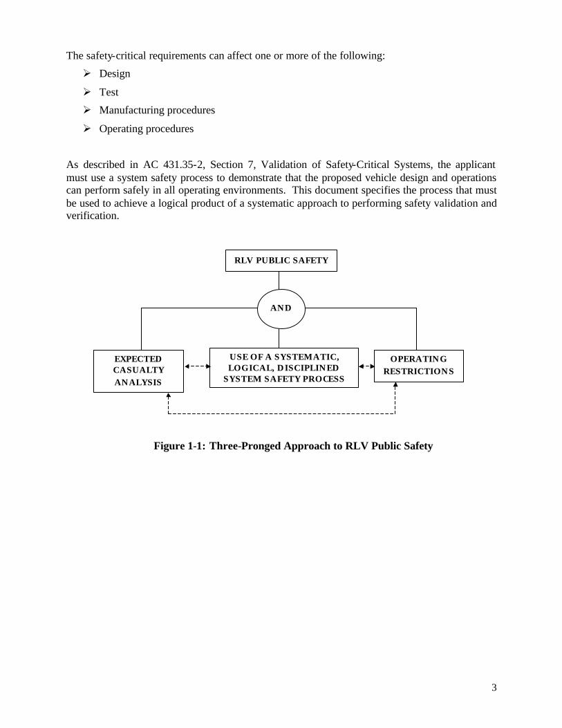
Figure 1-1 shows a 3-pronged approach to RLV public safety. This figure is taken from AC 431.35-2. The system safety process is a systematic way to identify, eliminate, mitigate, or control hazards to acceptable levels of risk throughout the lifecycle of an RLV. The system safety process, through the hazard analyses and associated mitigation measures, identifies the safety-critical systems and the associated set of safety-critical requirements.
3
The safety-critical requirements can affect one or more of the following:
Ø Design
Ø Test
Ø Manufacturing procedures
Ø Operating procedures
As described in AC 431.35-2, Section 7, Validation of Safety-Critical Systems, the applicant must use a system safety process to demonstrate that the proposed vehicle design and operations can perform safely in all operating environments. This document specifies the process that must be used to achieve a logical product of a systematic approach to performing safety validation and verification.
AND
EXPECTED CASUALTY ANALYSIS
USE OF A SYSTEMATIC, LOGICAL, DISCIPLINED
SYSTEM SAFETY PROCESS
OPERATING RESTRICTIONS
RLV PUBLIC SAFETY
Figure 1-1: Three-Pronged Approach to RLV Public Safety

4
2.0 RLV SAFETY VALIDATION AND VERIFICATION PLANNING
2.1 Overview
A V&V Plan describes both the V&V process and the implementation documents tha t will be used for a particular RLV system. The safety V&V process is intended to determine that the correct safety-critical system is being built (validation) and that the design solution has met all the safety-critical requirements (verification).
Examples of implementation documents typically described in the V&V Plan include the following items:
Ø Validation Table
Ø Validation Report
Ø Validated Requirements Document
Ø Master Verification Plan
Ø Verification Requirements and Specification Document
Ø Verification Requirements Traceability Matrix
Ø Requirements Verification Compliance Document
Refer to paragraph 2.7 and Appendix A for additional information regarding these items.
2.2 Levels of Safety-Critical Requirements
Safety-critical system development occurs in incremental steps, with corresponding levels of requirements. Validation and verification planning needs to address the repetition of the V&V process at all levels of safety-critical requirements. One example of levels of requirements follows:
Ø Piece part Ø Board Ø Component (box) Ø Assembly Ø System
2.3 Phases of a System’s Lifecycle
Validation and verification planning is not limited to the design and deployment phases. Instead, such planning applies to all phases of the lifecycle of an RLV system. The system lifecycle phases are as follows:
Conceptual ? ? R&D ? ? Design ? ? Deployment ? ? Operation ? ? Disposition
The V&V implementation documents will evolve with progressive lifecycle phases and with maturity within a given lifecycle phase. For example, the methods of safety verification will typically mature from analysis to test or demonstration as the RLV system flies. The V&V implementation documents must record the evolution. This evolution of the methods of safety verification and associated increased understanding of the system will provide the basis for assessment of an RLV moving from unproven to proven status.
5
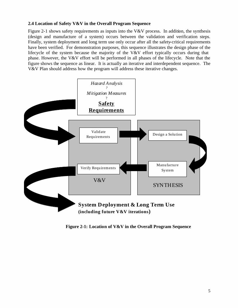
2.4 Location of Safety V&V in the Overall Program Sequence
Figure 2-1 shows safety requirements as inputs into the V&V process. In addition, the synthesis (design and manufacture of a system) occurs between the validation and verification steps. Finally, system deployment and long term use only occur after all the safety-critical requirements have been verified. For demonstration purposes, this sequence illustrates the design phase of the lifecycle of the system because the majority of the V&V effort typically occurs during that phase. However, the V&V effort will be performed in all phases of the lifecycle. Note that the figure shows the sequence as linear. It is actually an iterative and interdependent sequence. The V&V Plan should address how the program will address these iterative changes.
V&V
Validate Requirements
SYNTHESIS
Hazard Analysis ?
Mitigation Measures ?
Safety Requirements
Verify Requirements
Design a Solution
Manufacture System
System Deployment & Long Term Use (including future V&V iterations)
Figure 2-1: Location of V&V in the Overall Program Sequence
6
2.5 Validation
Validation has many definitions. For purposes of this guide, the following definition applies: Validation is the process that determines that the safety-critical requirements for an RLV and its operations are correct and complete.
The validation process confirms that the correct system is being built. To do this, the validation effort ensures unambiguous, correct, complete, consistent, operationally and technically feasible, and verifiable system requirements. In addition, this process demonstrates that the requirements for a system are well understood and that a design solution within the program limits is possible. Note that the requirements at the validation level should never specify the design solution, but rather the performance requirements.
The validation process consists of three phases: planning, evaluating, and documenting. The following paragraphs provide additional details regarding these phases. 2.5.1 Validation Planning In the planning phase, information is gathered from all applicable program and industry documents. Examples include the System Safety Program Plan, Hazard Report Forms, and Safety Requirements Document. Also during the planning phase, the safety requirements are entered into the Validation Table. Refer to paragraph 2.7.2 for additional information regarding validation tables. 2.5.2 Validation Evaluating The evaluation phase involves carefully assessing each safety requirement. The evaluation criteria are based on the need for the requirements to be complete and correct. Achieving completeness requires ensuring the absence of ambiguity or error. On the other hand, confirming that the correct set of requirements has been identified requires ensuring that no attributes have been omitted, and no requirement is extraneous. Sufficient effort must be exerted in this phase to avoid incorrect requirements. Formal safety requirements reviews can be helpful in aiding this effort. Identification and correction of nonconforming requirements are essential components of validation efforts. The following are characteristics of valid requirements:
Ø Design neutral (i.e., does not specify the design solution)
Ø Unambiguous
Ø Achievable with state-of-the-art technology (or reasonable advancement of technol-ogy)
Ø Verifiable
Ø Appropriate ambient and operational environments
Ø Derived requirements are supported by analysis
Ø Traceable (identified source)

7
Examples of nonconforming and conforming requirements are provided below to demonstrate the evaluation of validation requirements. (The italicized information below the nonconforming requirement provides the rationale for the nonconformance.)
Nonconforming Safety-Critical Validation Requirements
Conforming Safety-Critical Validation Requirements
The ultrahigh frequency (UHF) radio, Manufacturer X/Model Y, shall provide the ability to communicate with the operations control center.
Ø Design specific
Ø Has not defined the duration that communication is required
The UHF radio shall provide the ability to communicate with the operations control center throughout the entire mission.
The wing structural integrity shall be ade-quate to ensure no detrimental damage.
Ø Ambiguous; Does not specify loads
The wing shall not experience any detrimental damage when subjected to the flight loads specified in Program X Loads Document.
The two passenger seats shall be able to accommodate two grown men.
Ø Ambiguous; What size are two grown men?
Each of the two passenger seats will accommodate a 250-pound, 6 foot, 5 inches tall person.
The RLV mission shall be an enjoyable experience for the passengers.
Ø Not verifiable
2.5.3 Validation Documenting In the documentation phase, populating the Validation Table will comprise the majority of the validation effort. The Validation Report includes, but is not limited to, the Validation Table (see paragraph 2.7.2), summaries of validation efforts and results, lists of the nonconforming requirements, and associated lists of recommendations to bring the nonconforming requirements into compliance.
8
2.6 Verification
Verification has many definitions. For purposes of this guide, the following definition will be used:
Verification is the evaluation of an implementation to determine that applicable safety–critical requirements for an RLV and its operations are met.
The verification process ensures that the design solution meets or exceeds all validated safety requirements. A verified system shows measurable evidence that it complies with the overall system safety needs. Note that verification includes all activities performed on system elements to evaluate the progress and measure the effectiveness of evolving system products and processes in meeting validated safety requirements. The four acceptable methods of verifying safety requirements are as follows:
Ø Analysis
Ø Test
Ø Demonstration
Ø Inspection
Acceptability of one method over another depends on feasibility as well as maturity of an RLV and its operations. During the pre-application consultation process, AST evaluates the acceptability of proposed verification methods. Because each RLV system is unique in both design and operation, handling such evaluations on a case-by-case basis is appropriate.
2.6.1 Verification by Analysis Verification by analysis is typically used in lieu of or in addition to verification by test. This method involves technical or mathematical evaluation, mathematical models, simulations, algorithms, and circuit diagrams. Because of the inability of mathematical models to exactly model the complexities of real situations and environments, using conservative analytical methods and validating models is critical. For example, validating a ground test model provides additional confidence if the same modeling technique is used for the flight configuration.
Verification by similarity is a subset of verification by analysis. This is the process of assessing by review of prior acceptable data or hardware configuration and applications that the system element is similar or identical in design and manufacturing process to another system element that has been previously qualified to equivalent or more stringent specifications. Documentation must exist for the previously qualified system element. A “qualification by similarity” analysis is required when using this verification method. A critical part of the analysis is demonstrating that all aspects of the previous and the current system applications are significantly similar, including the predicted or actual environments. If there are items that are not significantly similar, “delta qualification” tests are performed to bring the item into full compliance with the requirements of the new application.

9
Verification by analysis is typically used in the following situations:
Ø When verification by similarity is possible
Ø When large factors of safety are used
Ø During the prototype phase
Ø When the other methods are either infeasible or inadequate
Wherever possible, this method is replaced with test or demonstration as the program evolves (e.g., once the vehicle begins to fly).
2.6.2 Verification by Test Verification by test involves the actual operation of system elements during ambient conditions or when subjected to expected operational environments to evaluate performance. Tests are to performed both on the ground and in flight. RLVs have a unique opportunity to use test verification methods through an envelope expansion test flight approach. There are two categories of tests: functional tests and environmental tests. Functional testing is an individual test or series of tests conducted on flight or flight- like hardware, software, and procedures at conditions equal to or less than design specifications. The intent is to verify that the system element performs satisfactorily in accordance with the design and performance specifications. These tests are usually conducted at ambient conditions and performed before and after environmental tests to verify system performance before the next test, operation, or both. Environmental testing involves an individual test or series of tests conducted on flight or flight-like hardware, software, and procedures at predicted or actual flight environments. Such tests typically include shock, vibration, acoustic, and thermal vacuum. Tests can apply to all phases during the evolution and on-going use of a system. Examples of environmental tests typically conducted at different phases of the lifecycle of a system are as follows:
Ø Proof of concept
Ø Development
Ø Qualification
Ø Acceptance
Ø Lot acceptance
Ø Integrated systems
Ø Launch countdown
Tests typically include instrumentation. The collection, analysis, and evaluation of substantive, quantitative test data are a part of the verification process. Recording of actual performance data is required. Test data provides the evidence of acceptable system performance and readiness to proceed with the planned V&V process. Test data also helps reduce uncertainties, resulting from the use of the verification by analysis method.
2.6.3 Verification by Demonstration Verification by demonstration involves using actual demonstration techniques to verify that the system element can perform its design functions under specified scenarios. Often requirements associated with reliability, transportability, maintainability, serviceability, and human engineering factors are verified using this method. The system elements may be instrumented
10
with quantitative limits of performance monitored; however, only checklists are required rather than recordings of actual performance data.
2.6.4 Verification by Inspection Verification by inspection is the physical examination of hardware, documentation, or both, to verify compliance of the feature with a predetermined criterion. These typically non-destructive inspection often use the human senses. Physical design and manufacturing features, workmanship, dimensions, quality, and physical conditions, such as cleanliness, surface finish, and locking hardware, are often verified using this method. Inspection of manufacturing records, and other documentation, can also be used by this method.
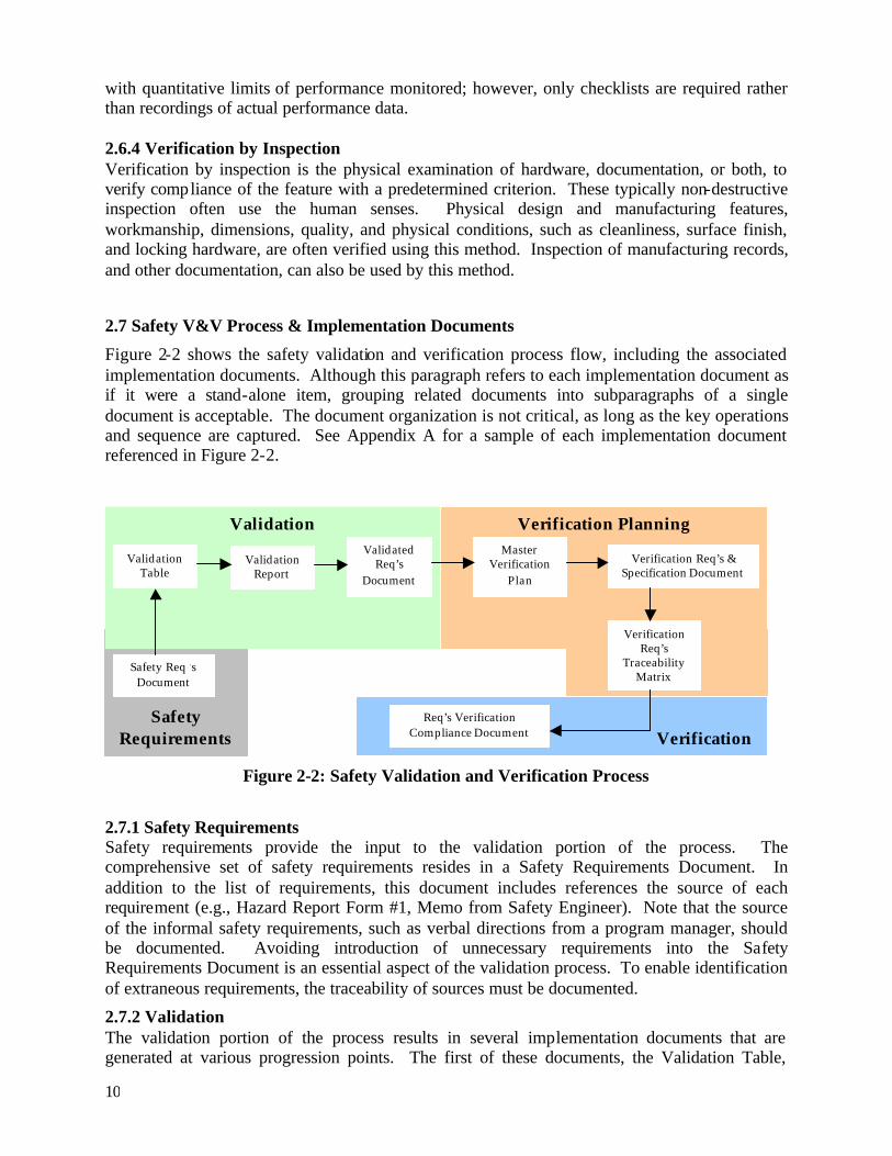
2.7 Safety V&V Process & Implementation Documents
Figure 2-2 shows the safety validation and verification process flow, including the associated implementation documents. Although this paragraph refers to each implementation document as if it were a stand-alone item, grouping related documents into subparagraphs of a single document is acceptable. The document organization is not critical, as long as the key operations and sequence are captured. See Appendix A for a sample of each implementation document referenced in Figure 2-2.
2.7.1 Safety Requirements Safety requirements provide the input to the validation portion of the process. The comprehensive set of safety requirements resides in a Safety Requirements Document. In addition to the list of requirements, this document includes references the source of each requirement (e.g., Hazard Report Form #1, Memo from Safety Engineer). Note that the source of the informal safety requirements, such as verbal directions from a program manager, should be documented. Avoiding introduction of unnecessary requirements into the Safety Requirements Document is an essential aspect of the validation process. To enable identification of extraneous requirements, the traceability of sources must be documented.
2.7.2 Validation The validation portion of the process results in several implementation documents that are generated at various progression points. The first of these documents, the Validation Table,
Safety Requirements
Validation Verification Planning
Verification
Safety Req ‘s Document
Validation Table
Validated Req’s
Document
Verification Req’s & Specification Document
Req’s Verification Compliance Document
Master Verification
Plan
Verification Req’s
Traceability Matrix
Figure 2-2: Safety Validation and Verification Process
Validation Report
11
consists of a matrix that includes, but is not limited to, the following information for each safety requirement:
Ø Requirement identifier
Ø Source
Ø Validation status (Yes/No)
Ø Requirement owner (individual).
A Validation Report is generated at the end of the validation activities. This report provides a summary of the validation efforts and results. These results consist of a list of nonconforming requirements with associated recommendations for correction. The Validation Table can either be referenced or attached to the Validation Report. Another document that is generated at the end of the validation activities is the Validated Requirements Document. This updated version of the Safety Requirements Document details corrections or updates implemented during validation efforts.
2.7.3 Verification Planning Once a set of validated safety requirements is produced, verification planning begins with the development of the Master Verification Plan (MVP). The MVP defines all the verification activities that show the ability of the system to meet the specified safety requirements, including test, analysis, demonstration, and inspection schedules. The MVP also describes the overall verification program as well as the planning information for all verification activities. Each major verification activity is defined and described in detail. The plan also provides a general schedule and sequence of events for major verification activities.
After completion of top- level verification planning, detailed documentation of how the proposed design solution will meet the validated safety requirements begins. Typically, each validated safety requirement transitions to a corresponding safety verification requirement. The safety verification requirements capture the design implementation specifications. In addition, the documentation describing the method that will be used to verify each requirement is generated. Both the list of safety verification requirements and the detailed discussion of the method of verification are documented in the Verification Requirements and Specification Document (VRSD). As a companion document to the VRSD, the Verification Requirements Traceability Matrix (VRTM) is a table that tracks each requirement identifier, source, verification method(s), level of requirement, relationship to the VRSD, and status. The MVP, VRSD, and VRTM are living documents that will be continually updated throughout the program. These documents form the basis for all verification efforts.
2.7.4 Verification With the beginning of verification activities, the VRTM serves as the framework of tracking verification efforts and recording completion of tasks. Once the VRTM has a positive completion status for all verification requirements, it becomes a part of the Requirements Verification Compliance Document (RVCD). The RVCD not only records completion of the verification effort but also identifies compliant and noncompliant verification safety requirements. Evidence of verification completion will either be included or referenced in the RVCD. Typically, the appropriate test, inspection, or analysis report will also be referenced in the RVCD.
12
3.0 CONCLUSION
Reusable Launch Vehicle (RLV) safety validation and verification planning is an essential effort in the System Safety Process. This document has provided an overall description of an accept-able safety validation and verification process, including the four acceptable methods of safety verification (analysis, test, demonstration, and inspection). Providing a guide on the validation and verification (V&V) process will maximize efficiency of an RLV applicant’s efforts during V&V planning. The specific use of the V&V process will be addressed during pre-application consultation and license evaluation.
13
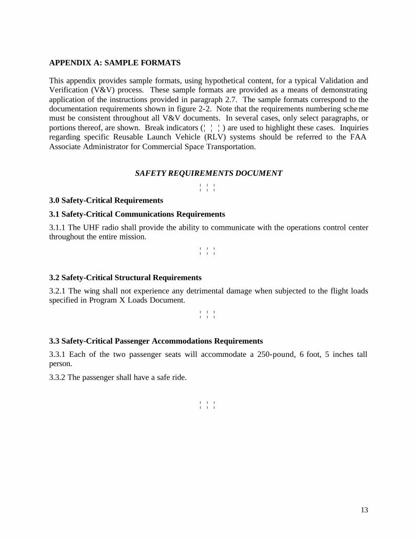
APPENDIX A: SAMPLE FORMATS
This appendix provides sample formats, using hypothetical content, for a typical Validation and Verification (V&V) process. These sample formats are provided as a means of demonstrating application of the instructions provided in paragraph 2.7. The sample formats correspond to the documentation requirements shown in figure 2-2. Note that the requirements numbering scheme must be consistent throughout all V&V documents. In several cases, only select paragraphs, or portions thereof, are shown. Break indicators (¦ ¦ ¦ ) are used to highlight these cases. Inquiries regarding specific Reusable Launch Vehicle (RLV) systems should be referred to the FAA Associate Administrator for Commercial Space Transportation.
SAFETY REQUIREMENTS DOCUMENT
¦ ¦ ¦
3.0 Safety-Critical Requirements
3.1 Safety-Critical Communications Requirements
3.1.1 The UHF radio shall provide the ability to communicate with the operations control center throughout the entire mission.
¦ ¦ ¦
3.2 Safety-Critical Structural Requirements
3.2.1 The wing shall not experience any detrimental damage when subjected to the flight loads specified in Program X Loads Document.
¦ ¦ ¦
3.3 Safety-Critical Passenger Accommodations Requirements
3.3.1 Each of the two passenger seats will accommodate a 250-pound, 6 foot, 5 inches tall person.
3.3.2 The passenger shall have a safe ride.
¦ ¦ ¦
14
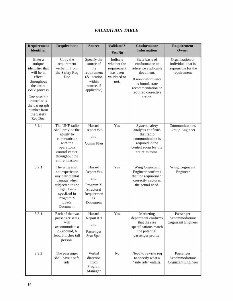
VALIDATION TABLE
Requirement Identifier
Requirement Source Validated?
Yes/No
Conformance Information
Requirement Owner
Enter a unique
identifier that will be in
effect throughout the entire
V&V process.
One possible identifier is
the paragraph number from
the Safety Req Doc.
Copy the requirement
verbatim from the Safety Req
Doc
Specify the source of
the requirement (& location
within source, if
applicable)
Indicate whether the requirement
has been validated or
not.
State basis of conformance or
reference applicable document.
If nonconformance is found, state
recommendation or required corrective
action.
Organization or individual that is
responsible for the requirement
3.1.1 The UHF radio shall provide the
ability to communicate
with the operations
control center throughout the entire mission.
Hazard Report #25
and
Comm Plan
Yes System safety analysis confirms
that radio communication is
required in the control room for the
entire mission.
Communications Group Engineer
3.2.1 The wing shall not experience any detrimental damage when
subjected to the flight loads specified in Program X
Loads Document.
Hazard Report #14
and
Program X Structural
Requirements
Document
Yes Wing Cognizant Engineer confirms
that the requirement correctly captures the actual need.
Wing Cognizant Engineer
3.3.1 Each of the two passenger seats
will accommodate a 250-pound, 6
foot, 5 inches tall person.
Hazard Report # 9
and
Passenger Seat Spec
Yes Marketing department confirms
that the size specifications match
the potential passenger profile.
Passenger Accommodations
Cognizant Engineer
3.3.2 The passenger shall have a safe
ride.
Verbal direction
from Program Manager
No
Need to rewrite req to specify what a
“safe ride” entails.
Passenger Accommodations
Cognizant Engineer
15
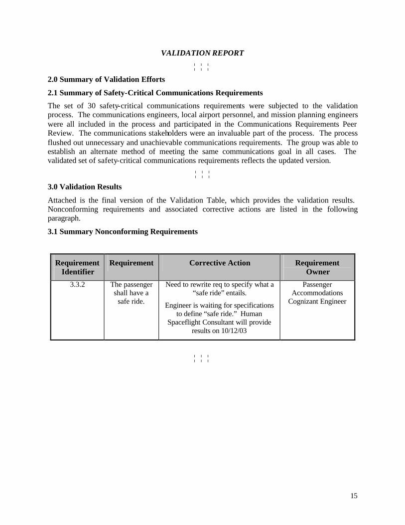
VALIDATION REPORT
¦ ¦ ¦
2.0 Summary of Validation Efforts
2.1 Summary of Safety-Critical Communications Requirements
The set of 30 safety-critical communications requirements were subjected to the validation process. The communications engineers, local airport personnel, and mission planning engineers were all included in the process and participated in the Communications Requirements Peer Review. The communications stakeholders were an invaluable part of the process. The process flushed out unnecessary and unachievable communications requirements. The group was able to establish an alternate method of meeting the same communications goal in all cases. The validated set of safety-critical communications requirements reflects the updated version.
¦ ¦ ¦
3.0 Validation Results
Attached is the final version of the Validation Table, which provides the validation results. Nonconforming requirements and associated corrective actions are listed in the following paragraph.
3.1 Summary Nonconforming Requirements
Requirement Identifier
Requirement Corrective Action Requirement Owner
3.3.2 The passenger shall have a
safe ride.
Need to rewrite req to specify what a “safe ride” entails.
Engineer is waiting for specifications to define “safe ride.” Human
Spaceflight Consultant will provide results on 10/12/03
Passenger Accommodations
Cognizant Engineer
¦ ¦ ¦
16
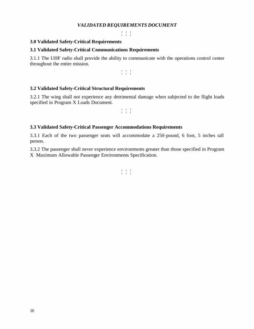
VALIDATED REQUIREMENTS DOCUMENT
¦ ¦ ¦
3.0 Validated Safety-Critical Requirements
3.1 Validated Safety-Critical Communications Requirements
3.1.1 The UHF radio shall provide the ability to communicate with the operations control center throughout the entire mission.
¦ ¦ ¦
3.2 Validated Safety-Critical Structural Requirements
3.2.1 The wing shall not experience any detrimental damage when subjected to the flight loads specified in Program X Loads Document.
¦ ¦ ¦
3.3 Validated Safety-Critical Passenger Accommodations Requirements
3.3.1 Each of the two passenger seats will accommodate a 250-pound, 6 foot, 5 inches tall person.
3.3.2 The passenger shall never experience environments greater than those specified in Program X Maximum Allowable Passenger Environments Specification.
¦ ¦ ¦
17
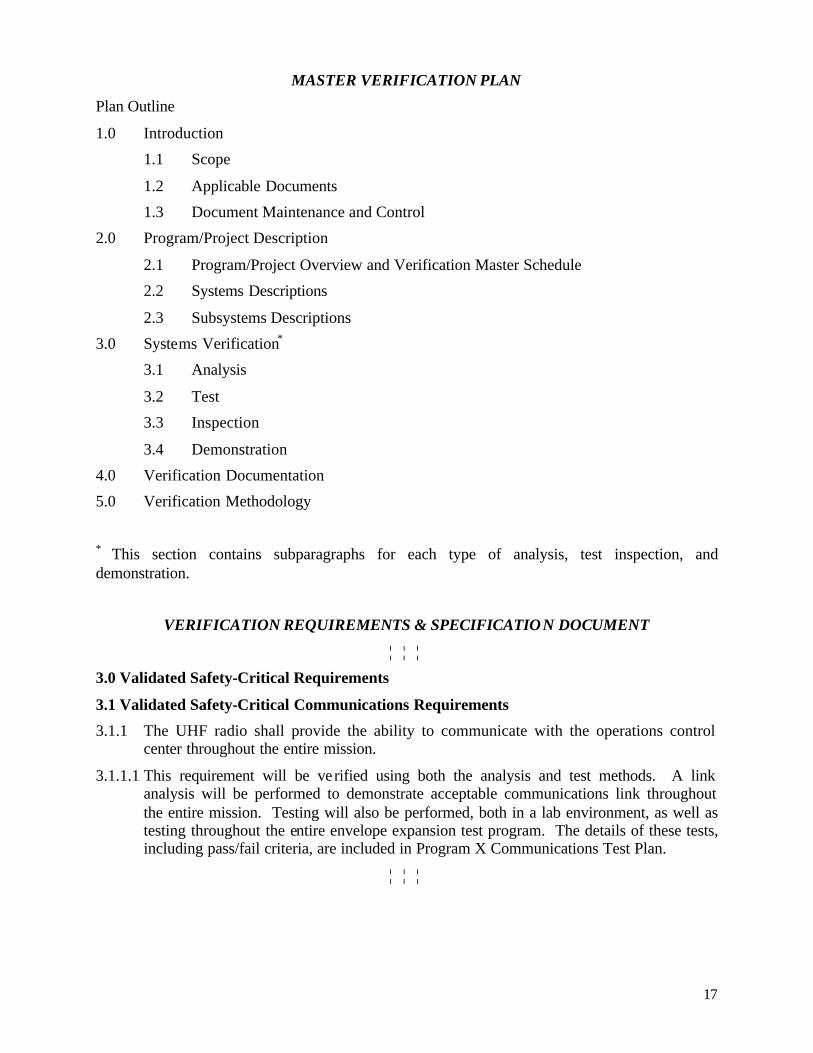
MASTER VERIFICATION PLAN
Plan Outline
1.0 Introduction
1.1 Scope
1.2 Applicable Documents
1.3 Document Maintenance and Control
2.0 Program/Project Description
2.1 Program/Project Overview and Verification Master Schedule
2.2 Systems Descriptions
2.3 Subsystems Descriptions
3.0 Systems Verification*
3.1 Analysis
3.2 Test
3.3 Inspection
3.4 Demonstration
4.0 Verification Documentation
5.0 Verification Methodology
* This section contains subparagraphs for each type of analysis, test inspection, and demonstration.
VERIFICATION REQUIREMENTS & SPECIFICATION DOCUMENT
¦ ¦ ¦
3.0 Validated Safety-Critical Requirements
3.1 Validated Safety-Critical Communications Requirements
3.1.1 The UHF radio shall provide the ability to communicate with the operations control center throughout the entire mission.
3.1.1.1 This requirement will be verified using both the analysis and test methods. A link analysis will be performed to demonstrate acceptable communications link throughout the entire mission. Testing will also be performed, both in a lab environment, as well as testing throughout the entire envelope expansion test program. The details of these tests, including pass/fail criteria, are included in Program X Communications Test Plan.
¦ ¦ ¦
18
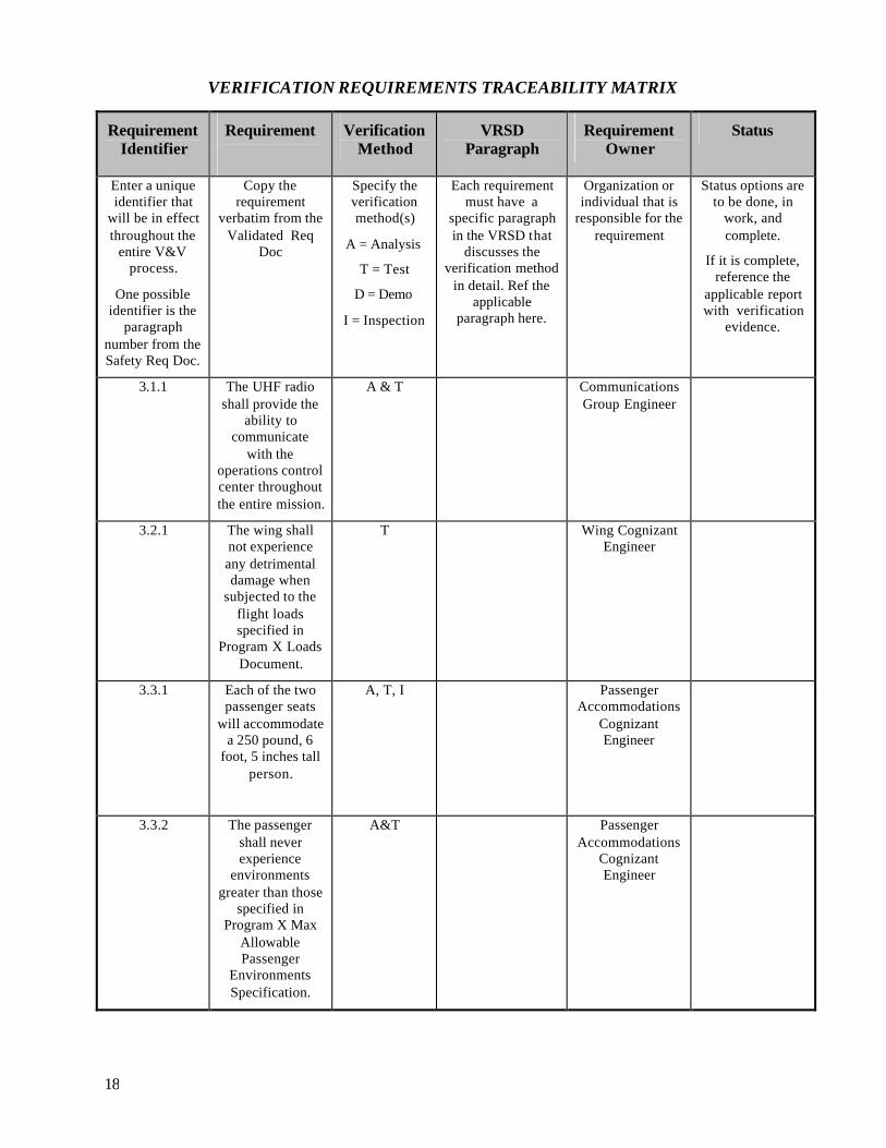
VERIFICATION REQUIREMENTS TRACEABILITY MATRIX
Requirement Identifier
Requirement
Verification Method
VRSD Paragraph
Requirement Owner
Status
Enter a unique identifier that
will be in effect throughout the
entire V&V process.
One possible identifier is the
paragraph number from the Safety Req Doc.
Copy the requirement
verbatim from the Validated Req
Doc
Specify the verification method(s)
A = Analysis
T = Test
D = Demo
I = Inspection
Each requirement must have a
specific paragraph in the VRSD that
discusses the verification method
in detail. Ref the applicable
paragraph here.
Organization or individual that is
responsible for the requirement
Status options are to be done, in
work, and complete.
If it is complete, reference the
applicable report with verification
evidence.
3.1.1 The UHF radio shall provide the
ability to communicate
with the operations control center throughout the entire mission.
A & T Communications Group Engineer
3.2.1 The wing shall not experience any detrimental damage when
subjected to the flight loads specified in
Program X Loads Document.
T Wing Cognizant Engineer
3.3.1 Each of the two passenger seats
will accommodate a 250 pound, 6
foot, 5 inches tall person.
A, T, I Passenger Accommodations
Cognizant Engineer
3.3.2 The passenger shall never experience
environments greater than those
specified in Program X Max
Allowable Passenger
Environments Specification.
A&T
Passenger Accommodations
Cognizant Engineer
19
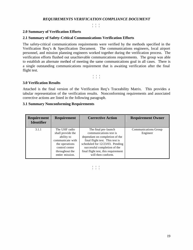
REQUIREMENTS VERIFICATION COMPLIANCE DOCUMENT
¦ ¦ ¦
2.0 Summary of Verification Efforts
2.1 Summary of Safety-Critical Communications Verification Efforts
The safety-critical communications requirements were verified by the methods specified in the Verification Req’s & Specification Document. The communications engineers, local airport personnel, and mission planning engineers worked together during the verification process. The verification efforts flushed out unachievable communications requirements. The group was able to establish an alternate method of meeting the same communications goal in all cases. There is a single outstanding communications requirement that is awaiting verification after the final flight test.
¦ ¦ ¦
3.0 Verification Results
Attached is the final version of the Verification Req’s Traceability Matrix. This provides a tabular representation of the verification results. Nonconforming requirements and associated corrective actions are listed in the following paragraph.
3.1 Summary Nonconforming Requirements
Requirement Identifier
Requirement Corrective Action Requirement Owner
3.1.1 The UHF radio shall provide the
ability to communicate with
the operations control center throughout the entire mission.
The final pre-launch communications test is
dependant on completion of the final flight test. This test is
scheduled for 12/23/03. Pending successful completion of the
final flight test, this requirement will then conform.
Communications Group Engineer
¦ ¦ ¦
20
REFERENCES
14 CFR 431. “Launch and Reentry of a Reusable Launch Vehicle, Final Rule.” Washington, D.C.: Government Printing Office, 2000. (See http://ast.faa.gov/ licensing/regulations/stat_reg.htm)
____. Reusable Launch and Reentry Vehicle System Safety Process. Advisory Circular 431.35-2, Washington, D.C.: FAA, 2000. (See http://ast.faa.gov/licensing/regulations/stat_reg.htm)
U.S. Department of Transportation, Federal Aviation Administration. “National Airspace System, System Engineering Manual.” Washington, D.C.: FAA, Version 1.0, November 1, 2002.
U.S. Department of Transportation, Federal Aviation Administration. “FAA Validation and Verification.” Training Class Material, Washington, D.C.: FAA, June 2003.
National Aeronautics and Space Administration. “NASA Systems Engineering Handbook.” SP-610S, Washington, D.C.: NASA, June 1995.