retrofit gas lift a practical solution to increase …
TRANSCRIPT

Seminar Nasional Cendekiawan 2015 ISSN: 2460-8696
597
RETROFIT GAS LIFT A PRACTICAL SOLUTION TO INCREASE PRODUCTION
Zikrina Khairun Nissa, Rachmat Sudibjo, Kartika Program Studi Teknik Perminyakan, Universitas Trisakti
Abstract
The purpose of this final assignment is to introduce an alternative new method of unconventional gas lift which also the first implementation done in Indonesia by ConocoPhillips Indonesia on their wells in North Belut, Natuna. though, artificial-lift technology is well established, alternative methods or new developments continue to play a role in solving problems and meeting production challenges. This final assignment will also describe the specific and detailed systems of this method, so hopefully the wells with this method could produce to its fully potential.
Keywords: Restrofit Gas Lift, Unconventional Gas Lift
Introduction
When a reservoir lacks sufficient energy for oil, gas and water to flow from wells at desired rates, supplemental production methods can help, gas and water injection for pressure support or secondary recovery to maintain well productivity, but artificial lift is needed when reservoir drives do not sustain acceptable rates or cause fluids to flow at all in some cases. Lift optimization to get the most fluid from a well or field at the lowest cost offers opportunities for substantial production gains in new wells or mature fields. When selecting and designing lift systems, engineers must consider reservoir and well parameters, but field development strategies should be factored in as well.Artificial-lift technology is well established, but alternative methods or new developments continue to play a role in solving problems and meeting production challenges. Alternative here means of deploying lift systems allow profitable production from previously uneconomic wells or fields.
Summarized Problems
North belut field was preliminary developed as gas field, after producing for couple of years, this field has been proved producing condensate and oil. All of North Belut wells are flowing naturally by reservoir pressure as long as the pressure is strong enough to lift gas and liquid to surface. Most of the wells are not equipped with artificial lift. As the reservoir continue depletes well ability to produce gas and liquid also drops until at some point when it passes the critical rate the well no longer able to flow and die. This condition referred as well load up.
Here are the summarized problems :
North Belut wells are getting reservoir pressure depletion and facing load up problem.
Artificial lift is required to extend run life of North Belut wells.
North Belut completions were not designed to accommodate artificial lift (gas lift, ESP, etc.) therefore unconventional type of artificial lift is required.
Basic Theory
Conventional Gas Lift
Gas Lift is the method of artificial lift that uses an external source of high-pressure gas to lift the well fluids by injecting compressed gas into the lower section of tubingthrough the casing–tubing annulus and an orifice installed in the tubing string.
Seminar Nasional Cendekiawan 2015 ISSN: 2460-8696
598
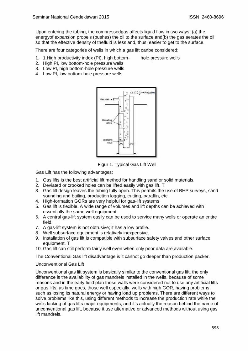
Upon entering the tubing, the compressedgas affects liquid flow in two ways: (a) the energyof expansion propels (pushes) the oil to the surface and(b) the gas aerates the oil so that the effective density of thefluid is less and, thus, easier to get to the surface.
There are four categories of wells in which a gas lift canbe considered:
1. 1.High productivity index (PI), high bottom- hole pressure wells 2. High PI, low bottom-hole pressure wells 3. Low PI, high bottom-hole pressure wells 4. Low PI, low bottom-hole pressure wells
Figur 1. Typical Gas Lift Well
Gas Lift has the following advantages:
1. Gas lifts is the best artificial lift method for handling sand or solid materials. 2. Deviated or crooked holes can be lifted easily with gas lift. T 3. Gas lift design leaves the tubing fully open. This permits the use of BHP surveys, sand
sounding and bailing, production logging, cutting, paraffin, etc. 4. High-formation GORs are very helpful for gas-lift systems 5. Gas lift is flexible. A wide range of volumes and lift depths can be achieved with
essentially the same well equipment. 6. A central gas-lift system easily can be used to service many wells or operate an entire
field. 7. A gas-lift system is not obtrusive; it has a low profile. 8. Well subsurface equipment is relatively inexpensive. 9. Installation of gas lift is compatible with subsurface safety valves and other surface
equipment. T 10. Gas lift can still perform fairly well even when only poor data are available.
The Conventional Gas lift disadvantage is it cannot go deeper than production packer.
Unconventional Gas Lift
Unconventional gas lift system is basically similar to the conventional gas lift, the only difference is the availability of gas mandrels installed in the wells, because of some reasons and in the early field plan those walls were considered not to use any artificial lifts or gas lifts, as time goes, those well especially, wells with high GOR, having problems such as losing its natural energy or having load up problems. There are different ways to solve problems like this, using different methods to increase the production rate while the wells lacking of gas lifts major equipments, and it’s actually the reason behind the name of unconventional gas lift, because it use alternative or advanced methods without using gas lift mandrels.

Seminar Nasional Cendekiawan 2015 ISSN: 2460-8696
599
Retrofit Gas Lift
There are several unconventional gas lift methods have been applied in today’s oil and gas industry, among them are, tubing punch and pack off gas lift systems also known as an Retrofit Gas Lift system.
Retrofit Gas Lift system, may provide a less risky and more economically viable means of bringing dead wells back on production or optimizing flowing wells.
Retrofit Gas Lift differs from Conventional Gas Lift in two obvious areas:
1. Gas lift gas wells
Typically Conventional Gas Lift is applied to oil wells to lighten the density of the liquid phase, gas lifting gas wells is les common since gas is much lighter and will generally flow naturally
2. Placed below production packer
Typically Conventional Gas Lift achieved through side-pocket mandrels and usually only be introduced no deeper than production packer.
Figur 2. Conventional Gas Lift VS Retrofit Gas Lift
Figur 3. RGL Lower BHA

Seminar Nasional Cendekiawan 2015 ISSN: 2460-8696
600
Figur 4. RGL Upper BHA
The advantages using the retrofit gas lift are :
1. No need for new completion, we can use the existing completion 2. Rigless job, relatively low cost 3. Point of injection as deep as possible
Methodology
In this final assignment author use PIPESIM WELL PERFORMANCE MODELING, this software can build optimize well performance through comprehensive modeling of completions and artificial lift systems. The PIPESIM simulator models multiphase flow from the reservoir to the wellhead and considers artificial lift systems. Well performance modeling capabilities in this simulator enables users to :
1. design optimal well completions and artificial lift systems
2. diagnose problems that are limiting well production potential
3. optimize production from existing wells by quantifying actions to increase flow rates
For the calculation the trial and error method is also use in this final assignment, trial and error is a fundamental method of solving problems. It is characterized by repeated, varied attempts which are continued until success, or until the agent stops trying, Trial and error is not a method of finding the best solution, nor is it a method of finding all solutions. It is a problem solving technique that is simply used to find a solution.
The formulized graphic presentation below will tell the sequence of this final assignment from start to finish, to help readers understand the flow of this final assignment better.

Seminar Nasional Cendekiawan 2015 ISSN: 2460-8696
601
Result
To identify the North Belut wells candidate, all wells have been reviewed by modeling the wells using Wellflo Program assisted by experts from COP Houston, based on the review and well model, 6 (six) wells have identified, but the author only choose two, X-07 and X-12, the details are classified as follows:
X-07
Current status : Natural Flow, Shut-In (Sept 2013)
Cum. Prod. (Sept 2013) : 255.4 MBO, 796 MMSCF
X-12
Current status : Natural Flow, still flowing
Cum. Prod. (Aug 2014) : 36 MBO, 111 MMSCF
To tell a contrast result from using artificial lift author choose to compare a shut in well to a flowing well.
1. Finding The Right Artificial Lift
Comparion between artificial lift
Based on well characteristics from both wells X-07 and X-12 as stated below, author had compared several artificial lifts, ESP, Conventional Gas Lift and Retrofit Gas Lift to find out the right artificial lift to be used on both wells

Seminar Nasional Cendekiawan 2015 ISSN: 2460-8696
602
Table.1. ESP VS Gas Lift
Table. 2. Conventional Gas Lift VS RGL
As can be seen from comparison tables above, it’s clearly stated that Gas Lift win over ESP and the Retrofit Gas Lift is the most convenience gas lift that can be used in X-07 and X-12 wells, from here we can discuss more about the design and application of the Retrofit Gas Lift
RGL Design
Figur 5. Main Part of Retrofit Gas Lift
The main parts of the Retrofit Gas Lift strings are cross flow diverter sub, slotted joint, and bottom gas injection valve.
Cross flow diverter sub allow two-way flow inside the string. Small part of tubing above the existing packer is perforated to allow gas from annulus flow thru the tubing. Cross flow diverter sub is located at this area.
Gas injection from annulus (yellow arrow) will go through cross flow diverter sub and diverted through coil tubing and gas injection valve to inject gas to liquid column. Liquid and gas from formation (green arrow) will flow through slotted joint into the cross flow diverter sub and directed to upper side of existing tubing to surface.
Retrofit Gas Lift string is set below existing subsurface safety valve, ensure well safety system is still active.

Seminar Nasional Cendekiawan 2015 ISSN: 2460-8696
603
Optimum Gas Injection Rate and Placing Depth
The optimum gas injection rate and RGL placing depth can be acknowledge after doing these steps with Pipesim Well Performance Modeling :
1. Building baseline based on wells data 2. Matching data with some parameters 3. Baseline use to build RGL model 4. Predicting optimum gas injection along with optimum depth
A. X.12
1. Building Baseline
This model build on pressure survey on September 2013. Qo @ September 2013 = 578.5 STB/d
Figur 6. X-12 Base Mode
l
2. Matching parameters
This model matched the pressure data (Pwf & Pr) at rate 578.5 STB/d with these following output result, GOR decreasing to 6922 SCF/STB and matched with Duns & Ros Flow Correlation, and this data used as baseline for future prediction.
3. RGL model
Because this well still flowing, and based on May 2015 production profile Qo = 273.1 STB/d Qg = 1.995 MMSCF/d. Current flowing pressure and reservoir pressure can be estimated
Figur 7 RGL Base Model
with the output result Pr = 1384.5 psi, Pwf = 711.4 Psi, This data used as baseline for
RGL Model
with RGL equipments set, the RGL model can be build and the result :

Seminar Nasional Cendekiawan 2015 ISSN: 2460-8696
604
Figur 8. X-12 RGL Base Model
With this RGL installation, the rate result,Qo : 264.08 STB/d, Qg : 1.833 MMSCF/d.
4. Optimum Gas Rate Injection and Setting Depth.
Total Depth of X-12 wells is 11.294 ft, Optimum Gas Rate Injection and Retrofit Gas Lift Setting depth can be predicted by trial method by inputting several depth and combine it with different gas injection rate. In this case, maximum gas rate injections for X-12 well is 2 MMSCF/d, and desired depth can be set as deep as possible, so the result can be seen on tables below.
Table 3. Pressure at Multiple Injection Rate
Figur 9. Pressure at Multiple Injection Rate
From comparing pressure at multiple injection rates it shows that, with X-12 static pressure 1679.4 Psia, optimum injection gas injection rate that can be use for RGL is 1.5 MMSCF/d, and setting depth result shown at table below.

Seminar Nasional Cendekiawan 2015 ISSN: 2460-8696
605
Table 4. Depth At Multiple Injection Rate
Figur 10. Injection rate at 1600 Psia at 9000 ft
From the trial method by inputting several depths at optimum gas injection rate 1.5 MMSCF/d, the result shows that RGL can be set with at 9000 ft.
B. X-07
1. Baseline
This model build based on pressure survey data on July 2014with Qo= 209.76 STB/d
Figur 11. X-07 Base Model
2. Matching Parameters
This model matched the pressure data (Pwf & Pr) at rate 209.76 STB/d with these following output result, GOR decreasing to 1045 SCF/STB and matched with Hagedorn & Brown RevisedFlow Correlation, and this data used as baseline for RGL model.
3. RGL model and Optimum Gas Rate Injection and Setting Depth
Due to well shut in, recent flowing pressure is not necessarily has to be predicted
4. Optimum Gas Rate Injection and Setting Depth
Total Depth of X-07 wells is 9.504 ft, Optimum Gas Rate Injection and Retrofit Gas Lift Setting depth can be predicted by trial method by inputting several depth and combine it with different gas injection rate. In this case, maximum gas rate injections for X-07 well is 2 MMSCF/d, and desired depth can be set as deep as possible, so the result can be seen on tables below.

Seminar Nasional Cendekiawan 2015 ISSN: 2460-8696
606
Table 5. Pressure at Multiple Injection Rate
Figur 12. Pressure at Multiple Injection Rate
From comparing pressure at multiple injection rates it shows that, with X-07 static pressure 1153.4 Psia, optimum injection gas injection rate that can be use for RGL is 2 MMSCF/d, and setting depth result shown at table below.
Table 6. Depth at Multiple Injection Rate
Figur 13. Injection Rate at 1000 Psia at 9300 ft.
Seminar Nasional Cendekiawan 2015 ISSN: 2460-8696
607
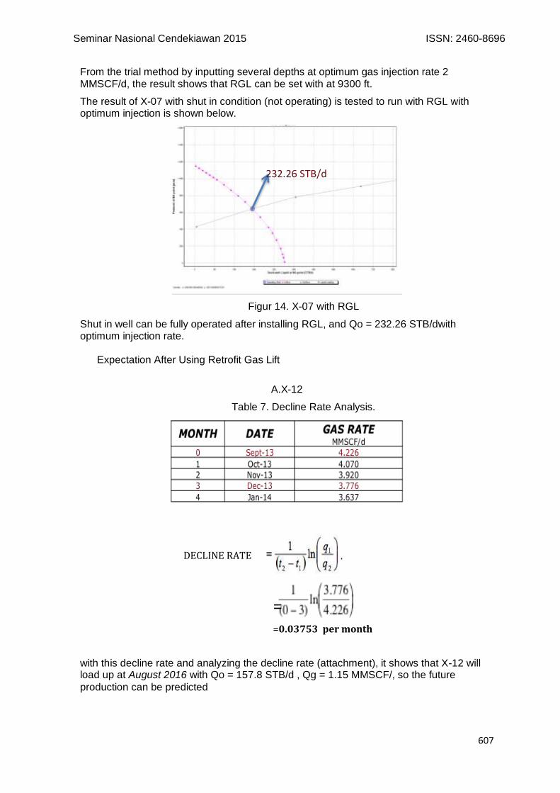
From the trial method by inputting several depths at optimum gas injection rate 2 MMSCF/d, the result shows that RGL can be set with at 9300 ft.
The result of X-07 with shut in condition (not operating) is tested to run with RGL with optimum injection is shown below.
Figur 14. X-07 with RGL
Shut in well can be fully operated after installing RGL, and Qo = 232.26 STB/dwith optimum injection rate.
Expectation After Using Retrofit Gas Lift
A.X-12
Table 7. Decline Rate Analysis.
with this decline rate and analyzing the decline rate (attachment), it shows that X-12 will load up at August 2016 with Qo = 157.8 STB/d , Qg = 1.15 MMSCF/, so the future
production can be predicted
232.26 STB/d
DECLINE RATE
=0.03753 per month
=

Seminar Nasional Cendekiawan 2015 ISSN: 2460-8696
608
Table 8. X-12 Production Prediction with RGL
INITIAL OIL RATE 204.8 STB/d
DECLINE RATE 0.0375 PER MONTH
LOAD UP RATE 72.3 STB/d
ECONOMIC RUNNING TIME 28 Months SEPTEMBER 2017
With that result, author predicting X-07 production gain after RGL installment.
Figur 15. With and Without RGL
The result shows that, with RGL the well lifetime can be extend up to 28 Months.Till September 2017, WithTotal Oil Gain = 110.6 MBBL
B. X-07
X-07 well is a shut in well, it means its already not flowing, the gain result from installing RGL shown below,
Table 9. X-07 Decline Rate Analysis
MONTH DATE
GAS RATE
MMSCF/d
0 Dec-13 1.464
1 Jan-14 1.394
2 Feb-14 1.326
3 Mar-14 1.262
4 Apr-14 1.201
DECLINE RATE
=0.0496 PER MONTH

Seminar Nasional Cendekiawan 2015 ISSN: 2460-8696
609
Table 10. X-07 Production Prediction with RGL
INITIAL OIL RATE 232.17 STB/d
DECLINE RATE 0.0496 PER MONTH
LOAD UP RATE 50 STB/d
ECONOMIC RUNNING TIME 30 Months November 2017
Figur 16. X-07 Decline Curve
The result shows that, with RGL the well lifetime can be extend up to 30 Months, till November 2017, WithTotal Oil Gain = 113.06 MBBLS
Conclusions
After comparing and analyzing several artificial lifts, the best artificial lift that suits X-12 and X-07 problems and provide more benefits, author could proudly stated that Retrofit Gas Lift matched all the criteria, from the installment to the design:
1. RGL is an unconventional gas lift because unlike typical conventional gas lift which gas lift valves already installed in gas lift mandrel
2. Retrofit Gas Lift can be use in Offshore Location. 3. Retrofit Gas Lift suitable for wells that are not equipped with any artificial lifts and still
have enough reserves. 4. Retrofit Gas Lift is practical because it doesn’t require a complete work over of the well
involving pulling the well apart and rerunning the completion. 5. Because of point 3, it cost less than other artificial lift. 6. Point of injection of a Retrofit Gas Lift system can be set as deep as possible. 7. Tubing punching in Retrofit Gas Lift installment step is to replace gas lift mandrel so
the well can have communication between tubing and annulus. 8. The optimum gas injection rate for X-12 well is 1.5 MMSCF/d and set at 9000 ft. 9. The optimum gas injection rate for X-07 well is 2 MMSCF/d and set at 9300 ft. 10. Production prediction after running with RGL can extend both wells lifetime. 11. X-12 production lifetime can be extended to 28 Months till September 2017 12. X-12 total oil gains 110.6 MBO. 13. X-07 production lifetime can be extended to 30 Months till November 2017. 14. X-07 total oil gains 113.06 MBO. 15. Installing RGL in X-07 and X-12 can deliver total uplift = 223.66 MBO.
Foreword
All praise are given to the almighty creator of the universe, Allah SWT, without whom I can not live, breathe and taste the sweetness of a success,After this long journey author would like to give her highest appreciation for Mr. Dr. Ir. Rachmat Sudibjo, Dipl, Ing. as the first advisor whom gives the author a lot of attention, approval and knowledge to finished the making of this thesis. Mrs. Kartika ST. MT. as the second advisor whom gave a lot of

Seminar Nasional Cendekiawan 2015 ISSN: 2460-8696
610
support, wisdom, and always encouraged the author to never gave up in making this thesis.
References Bradley H., “Petroleum Engineering Handbook”, Society of Petroleum Engineers, Richardson, TX, U.S.A, 1987 Brown, Kermit E., “The Technology Artificial Lift Methods”, Volume 2A, Penwell Publishing Co, Chapter 1, Tulsa, 1980. Brown, Kermit E., “The Technology Artificial Lift Methods”, Volume 4, Penwell Publishing Co, Chapter 7, Tulsa, 1984. Gas Lift, Book 6 of Vocational Training Series. API, Dallas, revised edition (1984) 65.
Guo, B., Lyons, W.C., Ghalambor, A., 2007. Petroleum Production Engineering. Elsevier.