retiming factor
TRANSCRIPT

8/6/2019 Retiming Factor
http://slidepdf.com/reader/full/retiming-factor 1/26
Retiming-Based Factorization forSequential Logic Optimization
SURENDRA BOMMU
Synopsys, Inc.
NIALL O’NEILL
Compaq
and
MACIEJ CIESIELSKI
University of Massachusetts
Current sequential optimization techniques apply a variety of logic transformations thatmainly target the combinational logic component of the circuit. Retiming is typically appliedas a postprocessing step to the gate-level implementation obtained after technology mapping.This paper introduces a new sequential logic transformation which integrates retiming withlogic transformations at the technology-independent level. This transformation is based onimplicit retiming across logic blocks and fanout stems during logic optimization. Its applica-tion to sequential network synthesis results in the optimization of logic across registerboundaries. It can be used in conjunction with any measure of circuit quality for which a fastand reliable gain estimation method can be obtained. We implemented our new techniquewithin the SIS framework and demonstrated its effectiveness in terms of cycle-time minimi-zation on a set of sequential benchmark circuits.
Categories and Subject Descriptors: B [Hardware]: ; B.6 [Hardware]: Logic DesignGeneral Terms: Algorithms, Design
Additional Key Words and Phrases: Finite state machines, retiming, sequential synthesis
1. INTRODUCTION
Over the years, sequential circuit synthesis has been a subject of intensiveinvestigation. Although synthesis of combinational logic has attained asignificant level of maturity, sequential circuit synthesis has been laggingbehind. This can be attributed mainly to the increase in circuit complexity
Authors’ addresses: S. Bommu, Synopsys, Inc., Marlboro, MA 01752; N. O’Neill, Compaq,Shrewsbury, MA 01545; M. Ciesielski, Department of Electrical & Computer Engineering,University of Massachusetts, Amherst, MA 01003.Permission to make digital/hard copy of part or all of this work for personal or classroom useis granted without fee provided that the copies are not made or distributed for profit orcommercial advantage, the copyright notice, the title of the publication, and its date appear,and notice is given that copying is by permission of the ACM, Inc. To copy otherwise, to
republish, to post on servers, or to redistribute to lists, requires prior specific permissionand/ or a fee. © 2000 ACM 1084-4309/00/0700–0373 $5.00
ACM Transactions on Design Automation of Electronic Systems, Vol. 5, No. 3, July 2000, Pages 373–398.

8/6/2019 Retiming Factor
http://slidepdf.com/reader/full/retiming-factor 2/26
caused by registers and feedback connections and to the deficiency of sequential equivalence checking. In the current state of affairs, sequentialnetworks are first optimized by applying combinational network transfor-mations to the logic between the register boundaries, and mapped into the
gate-level network. The resulting network is then often optimized byapplying the retiming transformation [Leiserson et al. 1983].
Retiming is the process of relocating registers across logic gates withoutaffecting the underlying combinational logic structure. In principle, retim-ing can be applied at various levels of synchronous system design. It hasbeen used in the optimization of the behavioral timing specification (bymoving the wait until statements in VHDL code [Wehn et al. 1994]), in RTLrestructuring, and architectural optimization [Potkonjak et al. 1993; Iqbalet al. 1993]. However, retiming gained its popularity mainly as a structural
transformation applied to gate-level circuits, where it can be used for
cycle-time minimization or for register minimization under cycle-timeconstraints [De Micheli 1994]. In addition to timing optimization, therehave been some attempts to apply it to low power design [Chandrakasan etal. 1995; Monteiro et al. 1992; Hachtel et al. 1994]. Recent research hassignificantly improved the efficiency and modeling accuracy of gate-levelretiming [Shenoy and Rudell 1994; Lalgudi and Papaefthymiou 1995].These and other works have sparked further interest in exploring retimingas a general optimization technique during architectural and logic synthe-sis.
Despite all these advances, potential for gate-level retiming to achieve
significant circuit optimization remains limited. Gate-level retiming, by itsconception, exploits only one degree of freedom in circuit optimization,namely, the relocation of registers. It is guided by the minimization of cycle-time which is based on a precomputed function of the location of registers in the network. The prospective logic simplification is not takeninto account in this optimization scheme. As a result, potential for theoptimization by subsequent resynthesis is very limited, as it is typicallyapplied to the logic between register boundaries.
This work aims at exploiting the additional degree of freedom offered byintroducing retiming early in the design process. In this paper we investi-
gate retiming as a technology-independent sequential transformation. Weintroduce a novel and efficient approach to synthesis and optimization of synchronous sequential circuits in which retiming is performed implicitly
during logic optimization, rather than as a separate gate-level optimizationstep. Our technique exploits an additional degree of freedom in synchro-nous optimization offered by implicit retiming across factorable logic ex-pressions and fanout stems. It also provides a simple means for initial statecomputation and guarantees the preservation of the initial state.
There have been several attempts to combine retiming with algebraicnetwork transformations in the quest to optimize the logic across registerboundaries. Peripheral retiming introduced by Malik et al. [1991] considersoptimization of the underlying combinational logic after a temporary relo-cation of registers to the periphery of the circuit. This approach, while
374 • S. Bommu et al.
ACM Transactions on Design Automation of Electronic Systems, Vol. 5, No. 3, July 2000.
8/6/2019 Retiming Factor
http://slidepdf.com/reader/full/retiming-factor 3/26
capable of optimizing the combinational logic exposed after the removal of registers to circuit periphery, does not explicitly target circuit performanceof the modified sequential circuit. It is driven solely by the optimization of the underlying combinational logic component; it cannot control the final
placement of registers. It also suffers from a limited mobility of registersduring the peripheral movement phase, and is applicable only to mapped,gate-level networks. DeMicheli [1991] introduced the concept of synchro-
nous divisors that can be used in logic optimization within and across theregister boundaries. However, no comprehensive approach to solving theresulting synchronous synthesis problem was provided. Furthermore, theproposed method operates on the structural specification of a synchronouscircuit and the prospective logic simplification is not explicitly taken intoaccount during the synchronous division. Lin [1993] developed a unifiedtheory for synchronous extraction of kernels/cubes and kernel intersections
to detect potential common divisors. The idea of implicit retiming wasintroduced by considering algebraic manipulations of synchronous expres-sions (algebraic expressions including dependence on time). Following theframework of combinational logic optimization, the synchronous extractioncommands can be applied to synchronous Boolean networks and iteratedwith node simplification and selective collapsing. Again, the prospectiveBoolean simplification (possible as a result of such an extraction) has notbeen explored.
Dey et al. [1992] proposed a method to improve the effectiveness of
retiming in synchronous circuits. The method is based on circuit restructur-
ing, using algebraic and redundancy manipulation transformations, in anattempt to eliminate the “retiming bottlenecks.” These transformationsenable further retiming to achieve the desired clock period. In this ap-proach the restructuring and retiming are separate steps, and the methodoperates on a structural representation of the circuit. Chakradhar et al.[1993] presented a technique to optimize the delay of a sequential circuitbeyond what is possible with optimal retiming. A set of special timingconstraints are derived from the circuit structure and used to resynthesizethe combinational component of the circuit. The modified circuit is subse-quently retimed. The constraints, if satisfied by the delay optimizer,
guarantee that the circuit is retimable and meets the desired cycle time.Retiming has also been used in the context of minimizing latency (ratherthan clock period) in pipelined circuits. A number of papers addressed aproblem of combining retiming with architectural and structural transfor-mations to minimize the latency and/or throughput. The scheme proposedby Potkonjak et al. [1993] uses retiming to enable algebraic transforma-tions that can further improve latency/throughput. The proposed processconsists of initial retiming, followed by algebraic transformation and by afinal retiming. The method is applicable to high performance embeddedsystems specified as data flowgraphs. Hassoun et al. [1996] introduced aconcept of architectural retiming which attempts to increase the number of registers on a latency-constrained path without increasing the overalllatency. These seemingly contradictory goals are achieved by implementing
Factorization for Sequential Logic Optimization • 375
ACM Transactions on Design Automation of Electronic Systems, Vol. 5, No. 3, July 2000.

8/6/2019 Retiming Factor
http://slidepdf.com/reader/full/retiming-factor 4/26
“negative” registers using precomputation and prediction techniques. Inthe process, the circuit is structurally modified to preserve its functionality.
Most of the techniques mentioned above operate on a structural represen-tation of the synchronous network. Furthermore, the cost function that
guides retiming in network optimization does not take into account thepotential for subsequent logic simplification. In contrast, our method oper-ates directly on functional specification, given in terms of synchronousBoolean expressions. It is an iterative synthesis process which integratesretiming with extraction, collapsing, and node simplification into onesynchronous transformation. The effect of this new transformation on logicsimplification is directly reflected in the cost function. While there existtechniques for generating sequential don’t-cares for synchronous circuitoptimization, global synchronous restructuring/optimization techniqueshave not been fully exploited. Our approach attempts to resolve these
deficiencies by explicitly taking into account the effect of retiming on logicsimplification. This is achieved by considering equivalence relations im-posed on registers due to implicit retiming across logic and fanout stems.The exploitation of these implicit relations (which can also be viewed as aspecial class of don’t-cares) offers an additional degree of freedom insequential optimization and enlarges the solution space searched. Ourapproach efficiently handles retiming across fanout stems (which is implicitin our scheme), while preserving the initial state. It provides a simplemethod to compute an initial state of the modified circuit, consistent withthe original network specification.
2. MOTIVATING EXAMPLE
Example 1. Consider a sequential circuit specified by the followingfunctional equations:
R1 r1r2, R2 a r3, R3 r1, z1 a r3, z2 br1r2 r3 (1)
where a, b are the inputs, z1, z2 are the outputs, r i the present states, and R i the next state variables. Our objective is to find an implementation of
the circuit with minimum cycle time. Assume, for simplicity, the unit delaymodel. The network, when mapped directly onto basic 2-input logic gates,results in the circuit shown in Figure 1(a). The longest delay in thecombinational logic, and hence cycle-time of the circuit is equal to 3 gatedelays. The circuit after retiming, shown in Figure 1(b), has a delay of 2gates. This solution (verified by SIS) can be obtained by forward retimingacross gate g1. It can be shown that classical retiming cannot reduce thedelay of the circuit any further.
We now show that it is possible to obtain a circuit by manipulatingdirectly its functional specification, with a delay of just 1 logic gate.Consider again the set of Eq. (1) specifying the circuit. A careful observation of equation z2 br1r2 r3 suggests that the subexpression r1r2 r3,
376 • S. Bommu et al.
ACM Transactions on Design Automation of Electronic Systems, Vol. 5, No. 3, July 2000.

8/6/2019 Retiming Factor
http://slidepdf.com/reader/full/retiming-factor 5/26
which depends solely on register variables, can be factored out and subse-quently retimed across. This retiming introduces a new register variabler4 r1r2 r3 in the expression for z2, so that
z2 br4, R4 R1 R2 R3 r1r2a r3 r1 r1. (2)
Here R i is the input to the register and r i is its output, a register variable.Now the modified circuit equations are
R1 r1r2, R2 a r3, R3 r1, R4 r1, z1 a r3, z2 br4.(3)
Furthermore, since R3 R4, we can replace each by a new variable R, thuseliminating one register. The final modified circuit equations are
R1 r1r2, R2 a r, R r1, z1 a r, z2 br. (4)
This corresponds to a circuit with only 3 gates and a cycle-time equal to 1unit (Figure 2(e)). The implications of such a functional modification of thecircuit specification deserve some explanation. Basically, such a procedurecorresponds to a series of retiming and logic simplification transformations,
as depicted structurally in Figure 2.Figure 2(a) shows the original network with the fanout node g1 dupli-
cated. The reason for this duplication is dictated by a need to the separatepath from g1 to z2 from other paths, in order to enable later retiming andlogic simplification transformations. Figure 2(b) shows the circuit after aseries of forward retiming transformations across fanout stems: (1) forwardretiming of register r1 across fanout stems x and y, creating registers r11 ,r12 and r13 ; (2) forward retiming of register r2 across fanout stem w, givingrise to registers r21, r22 ; and (3) forward retiming of register r3 acrossfanout stem v, creating registers r31 , r32 . To maintain the initial state of the retimed circuit, we need to impose the following constraints (equiva-lence relations) on register variables:
a
b
r2
g1
g3 g5
1
z2
g4r3
r1
a)
a
b g1
g4
g3
r1q
r3
g5
z1
z2
b)
Fig. 1. Retiming of an optimized circuit. (a) Original circuit; (b) retimed circuit.
Factorization for Sequential Logic Optimization • 377
ACM Transactions on Design Automation of Electronic Systems, Vol. 5, No. 3, July 2000.

8/6/2019 Retiming Factor
http://slidepdf.com/reader/full/retiming-factor 6/26
r11 r12 r13 r1, r21 r22 r2, r31 r32 r3 (5) At this point we can perform a forward retiming across a logic blockcomposed of gates g2, g3 (marked by the dotted area in Figure 2(b)) bymoving registers r12 , r22 , r32 from their inputs to the output of gate g3.Figure 2(c) shows the result of such a retiming, with new register r4 placedat the output of gate g3. Now the expression for R4 can be simplified (usingEq. (5)):
R4 r11r21a r31 r13 r1r2a r3 r1 r1 (6)
It is not surprising that the result is the same as given by Eq. (2). From thestructural point of view (which is shown here only for didactic purposes),the above simplification corresponds to logic simplification of the dottedarea in Figure 2(c), which leads to the circuit shown in Figure 2(d),described by Eq. (3). This simplification is made possible by recognizing theregister equivalence specified by Eq. (5). Finally, registers r3, r4 can beretimed backward across fanout stem u, leading to the optimized circuit inFigure 2(e), described by Eq. (4). As predicted by these equations, thecircuit has only three gates and its delay is equal to 1 unit, which is anoptimum solution in terms of the delay.
Notice that retiming cannot produce the above result because it wouldnot attempt retiming across g3, since this would only increase the delay to
g1
g4
g5
r13a
b
z2
z1
r4r21
r31
g2 g3
y
x
w
v
y
a
b
z2
g1
g4
g5
z1
r12 r21
r22
r13
g3 g2w
v
x
r31 r32
r11
r11
r3
a
b g1
r2
r1
z1
z2r4
u
g4
g5
a
b g1
r1
r2r
z1
z2u
g4
g5
a
b
z2
g1
g5
z1
r2
r1
r3
g3
g4
y
x
w
v
g2
c)
a) b)
d) e)
Fig. 2. Interpretation of the functional retiming. (a) Original circuit; (b) circuit after forwardretiming of r1, r2, r3 across the fanout stems; (c) circuit after retiming across g2, g3; (d)circuit after logic simplification of R4; (e) final retime-optimized circuit.
378 • S. Bommu et al.
ACM Transactions on Design Automation of Electronic Systems, Vol. 5, No. 3, July 2000.
8/6/2019 Retiming Factor
http://slidepdf.com/reader/full/retiming-factor 7/26

8/6/2019 Retiming Factor
http://slidepdf.com/reader/full/retiming-factor 8/26
must take into account the register equivalence imposed by this equiva-lence relation. An expression is called a retimable expression if all the variables in its support set are register variables. In this paper we limit ourattention to forward retiming involving retimable kernels.
Associated with each register is a pair of variables ( R i, r i), where R i isthe input to the register and r i is its output, referred to as a register
variable, so that r it R it 1. The variables r i and R i can also be
viewed as inputs and outputs, respectively, of the combinational part of thesequential network, with registers providing feedback paths.
4. THEORY AND ALGORITHMS
Traditional retiming across a logic gate (or a node) in a gate-level (orBoolean) network can be extended to a retiming across an arbitrary
subexpression (kernel or a cube) of the original functional specification.Such a retiming, combined with the extraction of a suitable expression,forms the basis of our new sequential transformation. We refer to it as theretiming-based factorization (RBF) transformation. This section describes
the operations involved in the RBF transformation.4.1 Retime Extraction
Example 2. Consider the sequential logic network represented by thefollowing equations and shown in Figure 5:
O1 i2 r3i1 r1r2i1
R1 r1r2i2 r3i2
R2 i1r2
R3 i2 i1r3 (7)
r1
r2
f
R1
R2
a
b f
R2
R1
R3 r3
f(a,b)
forward retiming
backward retiming
V V
( a ) ( b )
Fig. 3. Retiming of a logic node.
380 • S. Bommu et al.
ACM Transactions on Design Automation of Electronic Systems, Vol. 5, No. 3, July 2000.

8/6/2019 Retiming Factor
http://slidepdf.com/reader/full/retiming-factor 9/26
In these equations, i i denotes a primary input and r i denotes a register variable (present state variable). O i is a primary output function and R i isa register function (next state function).
Consider subexpression kr r1r2 r3, common to O1 and R1. Thissubexpression can be extracted from the expressions for O1 and R1 andused to create a new node in the network, V x5. Since all the inputs to kr areregister variables, this expression is forward retimable. Forward retimingacross V x5 leads to the creation of a new register represented by variables R4, r4. After retiming, the expression for R4 is then given in terms of
register input variables R i, as illustrated in Figure 6.This transformation can be expressed as a new operation, called retime-
extraction, which is the basis of our RBF transformation. For a givenretimable expression kr, the following steps implement retime-extraction:
(1) For every node f i of the network, containing expression kr, substitutethe expression with a variable rk.
(2) Introduce a new node corresponding to kr expressed in terms of registerinput variables, R i. Represent it by register function Rk.
(3) Introduce a new register ( Rk, rk).It should be emphasized that whenever the register variables in thesupport of retimable expression kr fan out to other functions, the retime-extract operation involves implicit retiming across fanout stems. In ourexample this applies to registers R2, R3 which have multiple fanouts.Consequently, a set of equivalence relations will be imposed on theseregisters and used in the subsequent logic simplification. On the otherhand, if a register involved in the retime-extraction fans out solely to theretimable expression, then it will be rendered redundant by the transfor-mation and can subsequently be removed. In the example, register R1 fansout only to the retime-extracted expression. Consequently, it can be re-moved later, along with the associated logic function (see Figures 6, 7, and 8).
2f
3f
2f
3f
f 1
f 1
R1 r1
V
V
V
1
3
2
R2 r2
R3 r3
V
V
2
3
forward
backward
Fig. 4. Retiming across a fanout stem.
Factorization for Sequential Logic Optimization • 381
ACM Transactions on Design Automation of Electronic Systems, Vol. 5, No. 3, July 2000.

8/6/2019 Retiming Factor
http://slidepdf.com/reader/full/retiming-factor 10/26
4.2 Collapsing and Simplification
In the next step, the node represented by a new variable Rk is collapsedinto its fanin nodes, as shown in Figure 7. The resulting expression is thensimplified. Notice the implicit duplication of logic, necessary to perform thecollapsing and simplification. This ensures that the functionality of the restof the network remains unchanged. In our case, logic for R1, R2, R3 isduplicated (see the area marked by the dotted line). The simplification ispossible, in effect, due to register equivalence imposed on fanout registers.For simplicity, in all the figures we use the same variable name for each of the registers obtained after retiming across a fanout.
In our case the collapsing and simplification leads to the followingexpression:
R4 R1 R2 R3 r4i2i1r2 i2 i1r3 i2 i1r3 (8)
O1
R1
R2
R3r3
r2
r1
R2
R3
R1
x1
Vx2
V
Vx3
Vx4
i1
i2
x1=i2 + r3i1 + r1r2i1
x4=i2 + i1r3
x2=r1r2i2 + r3i2
x3= i1r2
Fig. 5. The original network.
O1
R3
R1
R2
R3 r3
R2 r2
R1
R2
R3
r4R4
Vx5
x1V
Vx2
x5=R1R2 + R3
i1
i2
Vx3
Vx4
x4=i2 + i1r3
x2=r4i2
x1=i2 + i1r4
x3= i1r2
Fig. 6. Retime-extraction of r1r2 r3.
382 • S. Bommu et al.
ACM Transactions on Design Automation of Electronic Systems, Vol. 5, No. 3, July 2000.

8/6/2019 Retiming Factor
http://slidepdf.com/reader/full/retiming-factor 11/26
The simplified Boolean expression for Rk is also referred to as a retime-
expression REkr. It can be calculated for every retimable cube or kernelkr using the above procedure. The computation of REkr is central to theRBF transformation. In our example, the simplified expressions associatedwith node V x5 i2 i1r3 is identical to that of V x4; subsequently, R4 canbe derived directly from V x4, as shown in Figure 8(a). Furthermore, sincethe register functions R3, R4 are identical, the two registers could bemerged into one, provided that their initial states are identical, that is, r3
0
r40. Whether this is possible or not, depends on the initial conditions
imposed on the network; the issue of initial state computation is discussed
in the next section. Finally, notice that register function R1 is not used.This is because the register disappeared as a result of retime extractionacross r1r2 r3. Therefore, the combinational logic function associatedwith the register function can be deleted. The resulting network is shownin Figure 8(b). This network is a direct result of our RBF transformation.The retime-extraction, collapsing and simplification transformations areperformed implicitly through the computation of the retime-expression.
4.3 Initial State Computation
The correctness of the retime-extraction transformation is not complete
unless the initial conditions of the register, introduced by this transforma-tion, are resolved. The initial state computation upon forward retimingacross an arbitrary logic expression, as formally given in Touati andBrayton [1993], is straightforward. Implicit retiming across fanout stemsrequires additional conditions on the register value, namely the registerequivalence mentioned above. Let r i
0 be the initial value of a register R i, r i.For a retimable expression krr1, r2, ..., rn, the initial value of the register( Rk, rk), added by the retime-extraction, is given by rk
0 krr10, r2
0, ..., rn0.
For the example above, with retimable expression kr r1r2 r3, theinitial value of register ( R4, r4) is then given by r4
0 r10r2
0 r30. The
analysis of this expression reveals that we cannot blindly replace registers R3, R4 by a single register, unless either r1
0 or r20 can be guaranteed to be 0.
O1Vx2
R3 r3
R2 r2
R1
R2
R3
x1V
r4R4
Vx5V
x3
Vx4
Vx2
Vx3
Vx4
i1
i2
x1=i2 + i1r4
x2=r4i2
x4=i2 + i1r3
x4=i2 + i1r3
x2=r4i2
x5=R1R2 + R3
R3
R2
R1
x3= i1r2
x3= i1r2
Fig. 7. Collapsing of R4 into its fanin nodes.
Factorization for Sequential Logic Optimization • 383
ACM Transactions on Design Automation of Electronic Systems, Vol. 5, No. 3, July 2000.
8/6/2019 Retiming Factor
http://slidepdf.com/reader/full/retiming-factor 12/26
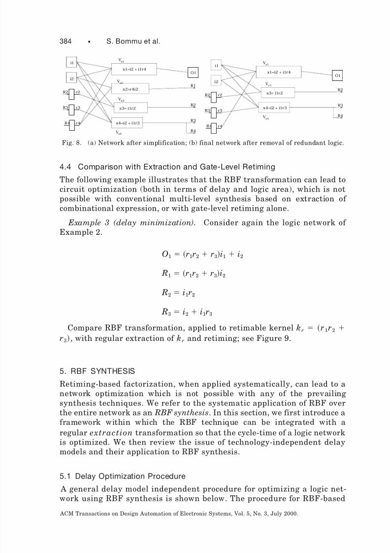
4.4 Comparison with Extraction and Gate-Level Retiming
The following example illustrates that the RBF transformation can lead tocircuit optimization (both in terms of delay and logic area), which is notpossible with conventional multi-level synthesis based on extraction of combinational expression, or with gate-level retiming alone.
Example 3 (delay minimization). Consider again the logic network of Example 2.
O1 r1r2 r3i1 i2
R1 r1r2 r3i2
R2 i1r2
R3 i2 i1r3
Compare RBF transformation, applied to retimable kernel kr r1r2
r3, with regular extraction of kr and retiming; see Figure 9.
5. RBF SYNTHESIS
Retiming-based factorization, when applied systematically, can lead to anetwork optimization which is not possible with any of the prevailingsynthesis techniques. We refer to the systematic application of RBF overthe entire network as an RBF synthesis. In this section, we first introduce aframework within which the RBF technique can be integrated with aregular extraction transformation so that the cycle-time of a logic networkis optimized. We then review the issue of technology-independent delaymodels and their application to RBF synthesis.
5.1 Delay Optimization Procedure
A general delay model independent procedure for optimizing a logic net-work using RBF synthesis is shown below. The procedure for RBF-based
R4
O1
R2 r2
R3 r3
r4R4
R1
R2
R3
Vx4
Vx3
Vx2
x1V
i2
x1=i2 + i1r4
x2=r4i2
x4=i2 + i1r3
i1
x3= i1r2
O1
R2 r2
R3 r3
r4R4
R4
R2
R3
Vx4
Vx3
x4=i2 + i1r3
x3= i1r2
x1V
i2
x1=i2 + i1r4
i1
Fig. 8. (a) Network after simplification; (b) final network after removal of redundant logic.
384 • S. Bommu et al.
ACM Transactions on Design Automation of Electronic Systems, Vol. 5, No. 3, July 2000.

8/6/2019 Retiming Factor
http://slidepdf.com/reader/full/retiming-factor 13/26
optimization involves the computation of retimable subexpressions of theBoolean logic associated with each node of the network. The candidatesubexpressions are then extracted or retime-extracted, depending on therelative gain of these transformations, resulting in an optimized logicnetwork. The following procedure gives the steps involved in networkoptimization using RBF synthesis.
(1) Select a set of candidate subexpressions to be extracted.
(2) For each candidate subexpression, do the following:(a) Check if it is retimable.(b) If retimable, estimate the delay gain of retime-extraction (r) and
regular extraction ( x). It should be emphasized that the gain r forthe retime-expression kr is based on all the transformations in- volved: retime-extraction, collapsing and simplification.
(c) If retime-extraction is estimated to give better gain, perform re-time-extraction. Otherwise, perform regular extraction.
In step (1), computing the set of subexpressions assumes the availabilityof the Boolean logic of individual nodes of the network in sum-of-products(SOP) form. The number of extractable common subexpressions which canbe identified is maximized if the nodes of the unoptimized network are
Fig. 9. Comparison of retiming-based factorization with extraction and retiming; feedback
loops R i 3 r i are omitted for simplicity.
Factorization for Sequential Logic Optimization • 385
ACM Transactions on Design Automation of Electronic Systems, Vol. 5, No. 3, July 2000.

8/6/2019 Retiming Factor
http://slidepdf.com/reader/full/retiming-factor 14/26
collapsed until their support variables are all primary inputs. This proce-dure, though effective, is impractical for large designs. In general, the faninof a node is collapsed into that node recursively until the SOP expression of individual nodes reaches a predefined limit (this is implemented as the
eliminate command in SIS).The order of extraction of the subexpressions also has an impact on the
extent of optimization possible. For example, the extraction of a non-retimable kernel could preclude the extraction of some other retimablekernels. Keeping this point in mind, the implementation of RBF synthesisalgorithm should provide the means by which the order of extraction of thesubexpressions can be controlled. In our implementation, options areprovided to favor the extraction of retimable subexpressions before extract-ing nonretimable subexpressions. This provides a means of controlling theorder of subexpression extraction to maximize the gain of RBF synthesis.
The quality of the results obtained with RBF synthesis clearly dependson the gain estimation and the delay models considered and the heuristicsused to accept a given kernel. In other words, the criteria used to assign the values of x and r for a given subexpression ultimately determine theeffectiveness of RBF synthesis. The remainder of this section is devoted tothe issue of delay modeling, and the heuristics used in determining thegain of retime-extraction over regular extraction.
5.2 Delay Models, Review
Delay modeling of an unmapped logic network is complicated by the lack of
a priori knowledge of delay characteristics of the logic gates. The bestmodel is that which can best predict the technology mapping accuratelyand efficiently. We first introduce some basic concepts required as abackground for delay modeling. The definitions are given here in terms of logic gates, but the principles can be applied to an unmapped Booleannetwork by extension.
The delay of a multi-level logic network consists of two components, node
delay and network delay. Node delay refers to the delay of the individualnodes of the network, possibly as a function of output loading, while thenetwork delay represents the maximum delay among all the input-output
paths in the network.Node delay. The delay of a node can be expressed as
d d I sf (9)
d I is the intrinsic delay of the node; it is defined as the difference betweenthe time when an input signal reaches half of its voltage swing and thetime when the rising/falling output signal reaches half of its voltage swing.The product sf represents the transition delay of the node, where s is a slew
rate, defined as the delay per unit fanout of the node, and f is the fanout
factor.Path delays. Path delay is the total delay incurred by a signal as it
propagates from one point in the network to another. The total delay
386 • S. Bommu et al.
ACM Transactions on Design Automation of Electronic Systems, Vol. 5, No. 3, July 2000.
8/6/2019 Retiming Factor
http://slidepdf.com/reader/full/retiming-factor 15/26
through a path is the sum of the intrinsic and transition delays along thepath.
Arrival time. The arrival time at a given point in the circuit is theearliest time at which the signal is available at that point. The arrival time
of the node is computed by forward traversal of the network, starting at theprimary inputs by adding node delay to the arrival time of the latestarriving input.
Required time. The required time at a node in the network is the latesttime at which the signal must be available at that node. The required timeis computed by a backward traversal of the network, starting at theprimary outputs by subtracting node delay from the required time of itsoutput.
Slack. Slack is the difference between the required time and arrival timeat a given node. A path with negative or zero slack is called a critical path.
We now review the delay models which differ in the kind of assumptionsmade about the node and the network delays.
5.2.1 Unit-Delay Model. The most general method of estimating thedelay in an unmapped Boolean network is based on the unit-delay model. Itmodels the delay of a node as a single unit and ignores the effect of outputloading on its delay. Although simplistic, the model gives a good approxi-mation for networks where the nodes are roughly of the same size.
5.2.2 Augmented Unit-Delay Model. This model, also called the fanout
delay model, is an extension to the unit-delay model. A single unit delay is
assigned to each node as before. However, the effect of output load on thedelay is taken into account by assigning a non-zero slew rate (Eq. (13)). Theslew rate is typically fixed, and equal to a fraction of the internal nodedelay, d I (assumed to be 0.2 in SIS).
5.2.3 Mapped Delay Model. Unlike the previous models, this model canonly be used on a mapped network, using the delay information stored inthe cell library. It is similar to the augmented unit delay model, except thatinternal delay and the slew rate information are specified in the pre-characterized library of logic cells. In order to compute the delay of a path,
delay trace is performed using the delay information stored in the library.
5.2.4 Approximate Timing Delay Models. In this approach, the delay of each node is estimated using an approximate delay model (discussedbelow); this estimated delay is used to compute the overall network delay.The arrival time at each node is computed by a forward traversal of thenetwork. The arrival times at the primary outputs give a good estimate of the overall network delay. Further information about the critical nodes inthe network can be obtained by a backward traversal of the network,enabling the computation of the required time and slack at each node. Thenodes with zero/negative slack represent a critical path in the network.
The approximate delay models give a better estimate of the overallnetwork delay than the unit delay or fanout delay models; however, they
Factorization for Sequential Logic Optimization • 387
ACM Transactions on Design Automation of Electronic Systems, Vol. 5, No. 3, July 2000.
8/6/2019 Retiming Factor
http://slidepdf.com/reader/full/retiming-factor 16/26
involve graph traversal algorithms which makes them inherently lessefficient. Furthermore, the accuracy of the delay model depends on theability to correctly estimate the delay of the individual nodes of thenetwork. In the remainder of this section we shall present some of the
techniques used to estimate the delay of an individual node of an un-mapped network.
Wallace model. The delay model introduced by Wallace et al. [1990]estimates the complexity of a node with a formula based on the decomposi-tion of the logic expression of the node onto a minimum-height tree. Anunmapped node in the network is stored in sum-of-products form. Fromthis representation the following formula gives a pessimistic estimate forthe arrival time at the output of the node:
Glog2 N Glog2 F max Ai F (10)
G is the delay of a two-input gate, N is the number of product terms, F ma x
is the fanin of the product term with the largest number of literals, Ai isthe arrival time of the latest arriving input, is an estimate of the averageslew rate for the target library, and F is the fanout number of the node.This model offers an upper bound on the mapped delay. The first term canbe viewed as the ‘breadth’ of the node and the second term as its ‘depth.’The third term gives a rough estimate of the input arrival times, and thefourth term is the transition delay.
TDC model. Probably the most accurate delay prediction strategy for
technology-independent logic optimization is the timing driven cofactor(TDC) model of Gutwin et al. [1992]. It is based on a fast decomposition of nodes using BDDs. The framework for calculating the unbalanced delay of a node is as follows. The idea is to estimate closely what a mappingprocedure will do. According to Gutwin et al. [1992], mapping proceduresare generally socialist in that they aim to place most of the logic in thepaths of the earliest arriving signals, and take the logic out of the laterarriving signals. In this way, the overall delay over all paths is minimized.Figure 10 illustrates the procedure:
(1) The input signals are partitioned into groups Gi based on their relativearrival times.
(2) The equivalent network of F i’s is derived by performing the cofactor of the node function F over the group G i.
(3) The balanced delay of each of the functional blocks F i is calculated.
(4) The total delay for F is given as the critical path through the resultingnetwork.
5.3 Delay Models Applied to Retiming-Based Factorization
This section gives some theoretical results on the reduction of cycle-timeresulting from the application of retiming-based factorization. First, some
388 • S. Bommu et al.
ACM Transactions on Design Automation of Electronic Systems, Vol. 5, No. 3, July 2000.

8/6/2019 Retiming Factor
http://slidepdf.com/reader/full/retiming-factor 17/26
additional notation is presented that will be useful in describing theseresults.
5.3.1 Notation
● f V is the Boolean function associated with node V .
● faninV is the set of nodes which fan in to node V .
● fanout PO V represents the set of primary outputs or input register variables which are in transitive fanin of node V .
● arrivaltime ne wV is the arrival time at the output of node V . It iscomputed after the corresponding transformation (retime-extraction orregular extraction) has taken place.
● delay N is the overall delay of the network prior to applying theextraction or retime-extraction transformation.
● delayne w N is the overall delay of the network after applying theextraction or retime-extraction transformation.
● V re tkr is a node associated with retimable kernel kr. In this case theregisters are simply forward retimed across the kernel and no collapsingis performed.
● R is a set of input register variables R i in the network.
5.3.2 Potential Cycle-Time Reduction. The unit-delay model will beused here to illustrate how retiming-based factorization can reduce thenetwork cycle-time.
THEOREM 1. If the delay of a network is estimated using a unit-delay
model, retiming-based factorization of a retimable subexpression kr does not
increase the delay of a sequential logic network.
PROOF. Consider an internal node V in the network. By the definition of arrival time:
arrivaltimeV Node DelayV maxa faninV
arrivaltimea (11)
Functional Blocks
Gi-1
Gi
Gi+1 Fi+1
Fi
Fi-1f
Fig. 10. Performance optimized logic network.
Factorization for Sequential Logic Optimization • 389
ACM Transactions on Design Automation of Electronic Systems, Vol. 5, No. 3, July 2000.

8/6/2019 Retiming Factor
http://slidepdf.com/reader/full/retiming-factor 18/26
Since we are using a unit delay model,
maxa faninV
arrivaltimea arrivaltimeV 1 (12)
Let V RE be the new internal node introduced by retime extraction of krr1, r2, ..rn. The retime expression REkr is then defined as REkr
kr R1, R2, ..., Rn.1 where R i are input register variables of the registersinvolved in the retiming of krr1, r2, ..rn. Then,
arrivaltimeV RE 1 maxa fanin Ri
arrivaltimea (13)
Using Eq. (12), the above equation becomes
arrivaltimeV RE max Ri faninV retkr
arrivaltime Ri11
max Ri faninV retkr
arrivaltime Ri (14)
But since R i faninV re tkr R, we have
arrivaltimeV RE max Ri R
arrivaltime Ri (15)
Therefore,arrivaltimeV RE delay N (16)
and hence the overall delay of the network will not increase under the unitdelay model. e
The above theorem shows that retime-extraction of a kernel does notincrease the topological longest path under the unit-delay model. Thefollowing corollary shows that, contrary to the retime-extraction, regularextraction can increase the overall delay of the network under the unit
delay model.Observation 1. If the delay of a network is estimated using a unit-delay
model, the regular extraction of a subexpression kr may increase the delayof a sequential logic network under certain condition.
PROOF. Consider kernel k extracted from a node V k. Assuming the unitdelay model, we have
1
Recall that, according to our notation, r it R it 1, so that k r R1, R2, . .., R n repre-sents a function that is expressed in variables from a previous time frame; refer to Figure 6 forclarification.
390 • S. Bommu et al.
ACM Transactions on Design Automation of Electronic Systems, Vol. 5, No. 3, July 2000.

8/6/2019 Retiming Factor
http://slidepdf.com/reader/full/retiming-factor 19/26
arrivaltimenew PO arrivaltime PO1, @ PO fanout POV k, (17)
where PO is a set of primary outputs or register input variables. Then, if the following condition holds,
delay N arrivaltime PO PO fanout POV k (18)
the cycle-time of the network increases, i.e.,
delaynew N delay N 1 (19)
e
In conclusion, under the unit delay model retime-extraction alwaysresults in lower delay than regular extraction. It can also be shown that
under an augmented (fanout) unit delay model, the retime-extractionmay—under certain conditions—adversely affect the network delay. This isdue to the fanout increase of the internal nodes and the subsequentchanges in the capacitive loading of the nodes affected by retime extraction[O’Neill 1997]. It may happen, for example, that a node on a critical pathfans out to a newly created node V kr, causing delay increase along thatpath (see node V 1 in Figure 12). Detailed analysis of this case is given inO’Neill [1997]. This problem can be readily identified by considering anaugmented delay model which takes into consideration the fanout factor.The issue of accurate delay gain estimation and targeting critical delay
regions will be discussed in the next section.
5.3.3 RBF Based on the Unit Delay Model. In this model, the decisionwhether to use retime-extraction or regular extraction is based on theestimate of the network delay using the unit-delay model. From Theorem 1and Observation 1 of Section 5, it is clear that retime-extraction can do noworse than regular extraction. However, indiscriminate application of retime-extraction could actually degrade the network performance. Tounderstand the reason for this it is important to understand the limitationsof the unit-delay model.
Network delay estimation using a unit-delay model is only justifiable if the size (complexity) of the individual nodes of the network is approxi-mately equal. Transformations to a logic network which do not alter therelative complexities of the nodes of a network can therefore be expected toproduce good results even when they are based on a unit-delay model. Thepreceding discussion provides the intuition for the heuristic used in retime-extraction transformation based on a unit delay model. According to thisheuristic, retime-extraction of a subexpression is considered preferable to aregular extraction if the complexity of the new node added to the networkby retime-extraction is no greater than the complexity of the node(s) fromwhich the subexpression has been extracted. The complexity of the individ-ual nodes is measured by the number of literals in the SOP form of theBoolean function of the node.
Factorization for Sequential Logic Optimization • 391
ACM Transactions on Design Automation of Electronic Systems, Vol. 5, No. 3, July 2000.

8/6/2019 Retiming Factor
http://slidepdf.com/reader/full/retiming-factor 20/26
Figure 11 illustrates the idea of cost estimation based on a simple literalcount. It is important to note that the two candidate nodes, kr and REkr,are not yet part of the network. The two transformations are beingevaluated as to which produces the better gain. The gains are computed asfollows: x, associated with kr (for standard extraction), and r, associatedwith REkr (for retime-extraction). In the figure
x maxlitcountV 1, litcountV 2, litcountV 3
r litcount REkr
Retime-extraction (which results in the addition of node REkr) is per-formed if r x. Note that the literal counts of nodes V 1, V 2, V 3 arecomputed before the extraction or retime-extraction; these counts, there-fore, include the literals of kr.
5.3.4 RBF Based on Appproximate Timing Delay Models. Extractionbased on the unit-delay model, described in the previous section, might notwork well for all designs. One of the primary limitations of this approach is
the lack of detailed delay information. In this section retime-extraction isreevaluated using the approximate timing delay model described in Section5.2.4.
The extraction (or retime-extraction) of a subexpression modifies thetopology of the network. Since the timing information of the networkchanges with any modifications made to the network, extraction of asubexpression might involve recomputing the arrival time information of the network. If timing data for all the nodes of the network need to bemodified after every extraction, the algorithm will be inefficient, and, forall practical purposes, ineffective. Fortunately, as explained in Section5.3.5, the extraction of a subexpression affects the timing of only a subset of the nodes of the network; efficient updating of the timing information iscentral to the use of this timing model for the RBF synthesis. The
k r
k rRE( ) rk
V1
V2
V3
Candidate node
Fig. 11. Delay gain estimation based on literal count.
392 • S. Bommu et al.
ACM Transactions on Design Automation of Electronic Systems, Vol. 5, No. 3, July 2000.

8/6/2019 Retiming Factor
http://slidepdf.com/reader/full/retiming-factor 21/26
remainder of this section describes the criteria used in making the compar-ison between the retime-extraction and regular extraction. It also discussesways to efficiently update the timing information after extracting a subex-pression.
The relative merits of the regular extraction and the retime-extractiontransformations are evaluated by comparing the latest arrival time origi-nating at the regularly extracted node, with the arrival time at the outputof the retime-extracted node. This involves forward traversal from the node
from which a candidate expression kr has been extracted, and a backwardtraversal from the retime-extracted node. That is, maxarrivaltime x i
over all output nodes o i of the network is compared with arrivaltime xk,where xk is the output of the retimed expression REkr, as illustrated inFigure 12.
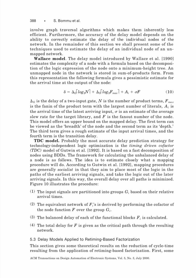
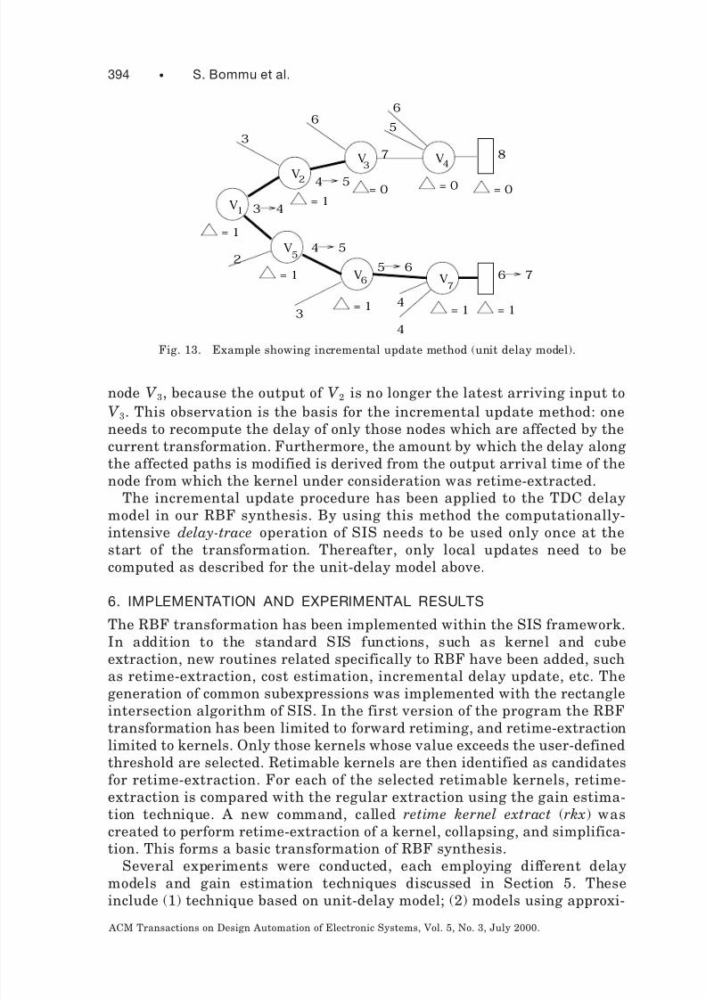
5.3.5 Estimation Procedure Using Incremental Update Method. Thissection discusses the implementation of the gain estimation procedurebased on the TDC model introduced in Section 5.2.4. In order to reducecomputation time, the gain estimation procedure uses an incremental
update method, illustrated in Figure 13. The numbers at the node inputsrefer to the arrival times, and those at the output of the node represent thearrival time change, before and after the application of the retime-extrac-tion or extraction transformation. The value of refers to the change inarrival time as a result of an extraction or retime-extraction of a subexpres-sion from V 1. The bold edges indicate the parts of the network affected bythe extraction.
Consider the following two cases. (1) For path V 1 3 V 7, the change inarrival time ripples through to the output, and causes the output delay tochange from 6 to 7 units. This is because the node inputs that are on the
path originating at V 1 are the latest arriving inputs to the nodes V 5, V 6 andV 7. (2) In the case of path V 1 3 V 4, the change in arrival times stops at
rk
N
V2
R k
r
I
RE(k r )
R
O
I
r
V
V1
xk
x
kr
ix
r
I
R
O
N
V
Fig. 12. Comparison of arrival times: (a) after regular extraction; (b) after retiming-based
factorization.
Factorization for Sequential Logic Optimization • 393
ACM Transactions on Design Automation of Electronic Systems, Vol. 5, No. 3, July 2000.
8/6/2019 Retiming Factor
http://slidepdf.com/reader/full/retiming-factor 22/26
node V 3, because the output of V 2 is no longer the latest arriving input toV 3. This observation is the basis for the incremental update method: oneneeds to recompute the delay of only those nodes which are affected by thecurrent transformation. Furthermore, the amount by which the delay alongthe affected paths is modified is derived from the output arrival time of thenode from which the kernel under consideration was retime-extracted.
The incremental update procedure has been applied to the TDC delaymodel in our RBF synthesis. By using this method the computationally-intensive delay-trace operation of SIS needs to be used only once at thestart of the transformation. Thereafter, only local updates need to becomputed as described for the unit-delay model above.
6. IMPLEMENTATION AND EXPERIMENTAL RESULTS
The RBF transformation has been implemented within the SIS framework.In addition to the standard SIS functions, such as kernel and cubeextraction, new routines related specifically to RBF have been added, suchas retime-extraction, cost estimation, incremental delay update, etc. The
generation of common subexpressions was implemented with the rectangleintersection algorithm of SIS. In the first version of the program the RBFtransformation has been limited to forward retiming, and retime-extractionlimited to kernels. Only those kernels whose value exceeds the user-definedthreshold are selected. Retimable kernels are then identified as candidatesfor retime-extraction. For each of the selected retimable kernels, retime-extraction is compared with the regular extraction using the gain estima-tion technique. A new command, called retime kernel extract (rkx) wascreated to perform retime-extraction of a kernel, collapsing, and simplifica-tion. This forms a basic transformation of RBF synthesis.
Several experiments were conducted, each employing different delaymodels and gain estimation techniques discussed in Section 5. Theseinclude (1) technique based on unit-delay model; (2) models using approxi-
V
V
V V
VV
V
1
2
3 4
5
67
= 1= 0 = 0 = 0
6
7
6
5
8
24
3
5
4
4
6
3 4
5
67
= 1
= 1
= 1 = 1 = 1
4 5
3
Fig. 13. Example showing incremental update method (unit delay model).
394 • S. Bommu et al.
ACM Transactions on Design Automation of Electronic Systems, Vol. 5, No. 3, July 2000.
8/6/2019 Retiming Factor
http://slidepdf.com/reader/full/retiming-factor 23/26
mate formula; and (3) the TDC delay. We tested our technique on a numberof sequential circuits from the ISCAS’91 benchmark set. Results arereported only for those circuits which contained retimable kernels. Thecircuits were input as logic networks in blif format, while its local functions
(nodes) were collapsed into SOP form. Each circuit was then optimizedusing RBF synthesis and independently synthesized with standard multi-level optimization of SIS. Finally, all the circuits were mapped onto thestandard SIS lib2. genlib library. The script used for RBF synthesis issimilar to script rugged of SIS, with the gkx command being replaced by therkx command of RBF synthesis. The final delays reported below werecomputed using the mapped delay model. The general structure of thescripts used in our experiments is given below:
script.rkx script. gkx
sweep sweep
collapse or eliminate threshold collapse or eliminate threshold
simplify simplify
rkx options gkx options
resub -a resub -a
sweep sweep
simplify simplify
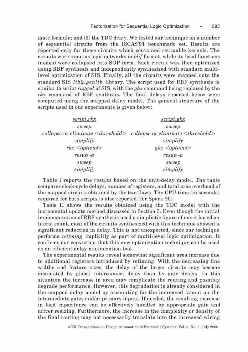
Table I reports the results based on the unit-delay model. The table
compares clock-cycle delays, number of registers, and total area overhead of the mapped circuits obtained by the two flows. The CPU time (in seconds)required for both scripts is also reported (for Spark 20).
Table II shows the results obtained using the TDC model with theincremental update method discussed in Section 5. Even though the initialimplementation of RBF synthesis used a simplistic figure of merit based onliteral count, most of the circuits synthesized with this technique showed asignificant reduction in delay. This is not unexpected, since our techniqueperforms retiming implicitly as part of multi-level logic optimization. Itconfirms our conviction that this new optimization technique can be used
as an efficient delay minimization tool.The experimental results reveal somewhat significant area increase due
to additional registers introduced by retiming. With the decreasing linewidths and feature sizes, the delay of the larger circuits may becomedominated by global interconnect delay than by gate delays. In thissituation the increase in area may complicate the routing and possiblydegrade performance. However, this degradation is already considered inthe mapped delay model by accounting for the increased fanout on theintermediate gates and/or primary inputs. If needed, the resulting increasein load capacitance can be effectively handled by appropriate gate anddriver resizing. Furthermore, the increase in the complexity or density of the final routing may not necessarily translate into the increased wiring
Factorization for Sequential Logic Optimization • 395
ACM Transactions on Design Automation of Electronic Systems, Vol. 5, No. 3, July 2000.

8/6/2019 Retiming Factor
http://slidepdf.com/reader/full/retiming-factor 24/26
length, which remains the best approximation of the interconnect delay.The average interconnect length, and its delay may remain unaffected.Finally, for the size of the circuits to which this technique is applicable(typically control circuits), the delay due to interconnect may not matter
that much. Performance of control circuits remains, at least for now,largely unaffected by the secondary effects of deep submicron technology.
7. CONCLUSIONS AND FUTURE WORK
Prevailing approaches to sequential optimization involve the application of combinational logic optimization and retiming techniques in isolation.Noting the drawbacks of such a scheme, we proposed an alternativeapproach which integrates retiming with combinational optimization tech-niques. Specifically, we demonstrated the advantages of integrating retim-ing with common kernel extraction and introduced a new retiming-basedfactorization (RBF) technique.
Table I. rkx vs gkx using Unit-Delay Model; Comparison of Mapped Circuits
Ckt rkx gkx % increase
Area Clk Reg CPU Area Clk Reg CPU Area Clk Reg CPU
s298 167040 9.59 25 20.3 145232 10.95 14 15.9 15 12 79 28s344 198592 13.50 17 40.5 187456 17.06 15 20.7 6 21 13 96s444 223648 9.51 24 25.6 203232 13.09 21 23.1 10 27 14 11s526 228288 10.10 25 26.2 208336 13.64 21 22.9 10 26 19 15s400 266800 11.05 28 36 211120 12.95 21 24.3 26 15 33 48
s9234 1156752 31.90 147 62.6 1101536 38.28 135 54.4 5 17 9 15s5378 1316832 2 5.29 189 58 1286672 2 6.31 162 56.3 2 4 17 14s510 245920 24.49 8 9 223184 28.20 6 7.9 10 13 33 5
s15850 3912912 104.1 538 276.6 3802480 108.23 504 269.4 3 4 7 3s1488 629648 42.72 13 65.4 607840 39.67 6 39.7 4 7 117 64s382 329904 10.63 33 39.8 215760 13.82 21 23.7 53 23 57 68
Table II. rkx vs gkx using TDC Model; Comparison of Mapped Circuits
Ckt rkx- TDC gkx % increase
Area Clk Reg CPU Area Clk Reg CPU Area Clk Reg CPU
s298 202768 8.91 17 44.5 145232 10.95 14 15.9 40 19 21 280s344 229216 12.59 17 42.0 187456 17.06 15 20.7 22 26 13 203s444 218080 10.36 23 43.3 203232 13.09 21 23.1 7 21 10 187s526 224112 12.0 22 92.4 208336 13.64 21 22.9 8 12 5 403s400 330368 9.49 27 46.3 211120 12.95 21 24.3 57 27 29 191
s9234 1186448 32.94 149 146.8 1101536 38.28 135 54.4 8 14 10 270
s5378 1307552 25.33 192 126.8 1286672 26.31 162 56.3 2 4 19 225s510 245920 24.49 8 29.3 223184 28.20 6 7.9 10 13 33 371s15850 3814080 108.42 505 4148.5 3 802480 108.23 504 269.4 0 0 0 1540s1488 609232 39.03 6 1974.1 607840 39.67 6 39.7 0 2 0 4972s382 260768 11.33 25 84.7 215760 13.82 21 23.7 21 18 19 357
396 • S. Bommu et al.
ACM Transactions on Design Automation of Electronic Systems, Vol. 5, No. 3, July 2000.
8/6/2019 Retiming Factor
http://slidepdf.com/reader/full/retiming-factor 25/26
Experimental results confirm our conviction of the potential applicationof the presented approach to clock cycle minimization. One can notice thatthe results do not seem to depend much on the accuracy of the delayestimation method used. This suggests the limitation of the entire synthe-
sis process, which is inherently greedy; a transformation is applied to thenetwork if the estimated gain exceeds a predefined threshold, withoutregard to the consequences of that transformation on the subsequenttransformations applied to other nodes. An alternative approach would beto consider a subset of retimable expressions and estimate their collectivegain, instead of dealing with one expression at a time. Future research inthis area should investigate such alternatives.
While the presented RBF technique targeted the cycle time minimiza-tion, we believe that its application is not limited to delay optimization. Itseems also applicable to other metrics for which reliable and efficient gain
estimation methods are available; these include logic area (possibly underdelay constraint), power (as addressed in system POSE [Iman 1995]),testability, and reliability.
REFERENCES
CHAKRADHAR, S. T., DEY, S., POTKONJAK , M., AND ROTHWEILER, S. G. 1993. Sequential circuitdelay optimization using global path delays. In Proceedings of the 30th ACM/IEEE
International Conference on Design Automation (DAC ’93, Dallas, TX, June 14–18), A. E.Dunlop, Ed. ACM Press, New York, NY, 483–489.
CHANDRAKASAN, A. P., POTKONJAK , M., MEHRA, R., R ABEY, J., AND BRODERSON, R.W. 1995. Optimizing power using transformations. IEEE Trans. Comput.-Aided Des.
Integr. Circuits 14, 1 (Jan. 1995), 12–31.DE MICHELI, G. 1991. Synchronous logic synthesis: Algorithms for cycle-time
optimization. IEEE Trans. Comput.-Aided Des. Integr. Circuits Syst. 10, 1 (Jan. 1991),63–73.
DE MICHELI, G. 1994. Synthesis and Optimization of Digital Circuits. McGraw-Hill, Inc.,New York, NY.
DEY, S., POTKONJAK , M., AND ROTHWEILER, S. G. 1992. Performance optimization of sequentialcircuits by eliminating retiming bottlenecks. In Proceedings of the 1992 IEEE/ACM
International Conference on Computer-Aided Design (ICCAD ’92, Santa Clara, CA, Nov.8 –12), L. Trevillyan, Ed. IEEE Computer Society Press, Los Alamitos, CA, 504–509.
GUTWIN, P., MCGEER, P., AND BRAYTON, R. 1992. Delay rrediction for technology-independentlogic equations. In Proceedings of the IEEE International Conference on Computer
Design, IEEE Computer Society Press, Los Alamitos, CA, 468– 471.H ACHTEL, G. D., HERMIDA, M., P ARDO, A., PONCINO, M., AND SOMENZI, F. 1994. Re-encoding
sequential circuits to reduce power dissipation. In Proceedings of the 1994 IEEE/ACM
International Conference on Computer-Aided Design (ICCAD ’94, San Jose, CA, Nov. 6–10,1994), J. A. G. Jess and R. Rudell, Eds. IEEE Computer Society Press, Los Alamitos, CA,70–73.
H ASSOUN, S. AND EBELING, C. 1996. Architectural retiming: Pipelining latency-constrainedcircuits. In Proceedings of the 33rd Annual Conference on Design Automation (DAC ’96, Las Vegas, NV, June 3–7), T. P. Pennino and E. J. Yoffa, Eds. ACM Press, New York, NY,708–713.
IMAN, S. AND PEDRAM, M. 1995. Logic extraction and factorization for low power. In Proceedings of the 32nd ACM/IEEE Conference on Design Automation (DAC ’95, San
Francisco, CA, June 12–16, 1995), B. T. Preas, Ed. ACM Press, New York, NY, 248 –253.IQBAL, Z., POTKONJAK , M., DEY, S., AND P ARKER, A. 1993. Critical path minimization usingretiming and algebraic speed-up. In Proceedings of the 30th ACM/IEEE International
Factorization for Sequential Logic Optimization • 397
ACM Transactions on Design Automation of Electronic Systems, Vol. 5, No. 3, July 2000.
8/6/2019 Retiming Factor
http://slidepdf.com/reader/full/retiming-factor 26/26
Conference on Design Automation (DAC ’93, Dallas, TX, June 14–18), A. E. Dunlop, Ed. ACM Press, New York, NY, 573–577.
L ALGUDI, K. N. AND P APAEFTHYMIOU, M. C. 1995. DELAY: An efficient tool for retiming withrealistic delay modeling. In Proceedings of the 32nd ACM/IEEE Conference on Design
Automation (DAC ’95, San Francisco, CA, June 12–16, 1995), B. T. Preas, Ed. ACM Press,
New York, NY, 304–309.LEISERSON, C., ROSE, F., AND S AXE, J. 1983. Optimizing synchronous circuitry by retiming. In
Proceedings of the Third Caltech Conference on VLSI , 87–116.LIN, B. 1993. Restructuring of synchronous logic circuits. In Proceedings of the 1993
European Conference on Design Automation (EDAC ’93 EURO-ASIC, Feb.), 205–209.M ALIK , S., SENTOVICH, E., BRAYTON, R., AND S ANGIOVANNI-VINCENTELLI, A. 1991. Retiming and
resynthesis: Optimizing sequential networks with combinational techniques. IEEE Trans.
Comput.-Aided Des. Integr. Circuits Syst. 10, 1 (Jan. 1991), 74–84.MONTEIRO, J . , DEVADAS, S., AND GHOSH, A. 1993. Retiming sequential circuits for low
power. In Proceedings of the International Conference on Computer-Aided Design (ICCAD’93, Santa Clara, CA, Nov. 7–11), M. Lightner and J. A. G. Jess, Eds. IEEE ComputerSociety Press, Los Alamitos, CA, 398–402.
O’NEILL, N. 1997. Sequential logic synthesis based on retiming-based factorization. Master’sThesis. University of Massachusetts Press, Amherst, MA.
POTKONJAK , M., DEY, S., IQBAL, Z., AND P ARKER, A. 1993. High performance embedded systemoptimization using algebraic and generalized retiming techniques. In Proceedings of the
IEEE International Conference on Computer Design, IEEE Computer Society Press, Los Alamitos, CA, 498–504.
SHENOY, N. AND RUDELL, R. 1994. Efficient implementation of retiming. In Proceedings of the
1994 IEEE/ACM International Conference on Computer-Aided Design (ICCAD ’94, San Jose,CA, Nov. 6–10, 1994), J. A. G. Jess and R. Rudell, Eds. IEEE Computer Society Press, Los Alamitos, CA, 226–233.
SINGHAL, V., PIXLEY, C., RUDELL, R. L., AND BRAYTON, R. K. 1995. The validity of retimingsequential circuits. In Proceedings of the 32nd ACM/IEEE Conference on Design Automa-
tion (DAC ’95, San Francisco, CA, June 12–16, 1995), B. T. Preas, Ed. ACM Press, New York, NY, 316–321.TOUATI, H . J . AND BRAYTON, R. K. 1993. Computing the initial states of retimed
circuits. IEEE Trans. Comput.-Aided Des. Integr. Circuits Syst. 12, 1 (Jan. 1993), 157–162.W ALLACE, D. AND CHANDRASEKHAR, M. 1990. High level delay estimation for technology-
independent logic equations. In Proceedings of the IEEE International Conference on
Computer Aided Design, IEEE Computer Society Press, Los Alamitos, CA.WEHN, N . , BIESENACK , J . , DUZY, P . , L ANGMAIER, T . , MÜNCH, M. , PILSL, M., AND RUMLER,
S. 1994. Scheduling of behavioral VHDL by retiming techniques. In Proceedings of the
European Conference on Design Automation (EURO-DAC ’94, Grenoble, France, Sept.19 –23, 1994), J. Mermet, Ed. IEEE Computer Society Press, Los Alamitos, CA, 546–551.
Received: November 1997; accepted: September 1998
398 • S. Bommu et al.
ACM Transactions on Design Automation of Electronic Systems, Vol. 5, No. 3, July 2000.