resumo manases tello ruiz - técnico lisboa - autenticação · t draught lpp length between ......
TRANSCRIPT
DYNAMICS AND HYDRODYNAMICS FOR FLOATING WAVE ENERGY CONVERTERS
Manases Tello Ruiz
Dissertação para obtenção do Grau de Mestre em Engenharia e Arquitectura Naval
ABSTRACT The work described in the present thesis is a short review of the most common wave energy converter operating nowadays all around the world. Furthermore, a discussion of the hydrodynamic and dynamic performance of one device targeted to harness ocean wave energy by rolling motion is presented. To perform the study, the coastal zone of Leixões, Portugal, is chosen; and main hull characteristics are modified aiming to match the fundamental period of the operational zone. Frequency domain transfer functions are obtained, viscous roll damping corrections are introduced, and the power take off influence is also taken into account. Moreover, analysis based on irregular seas states is made aiming to estimate the responses in a real sea state. The results show that the designed geometrical shapes guaranties amplitudes in roll higher than 3º for the most common zero crossing period and the observed significant wave height. Further, the analysis of the mooring system reveals that less heavy materials for the mooring line reduces the vertical loads on the fairlead and the anchor point. In addition, subsurface floaters may be added to the mooring system in order to further reduce the load, especially the vertical load at the fairlead. NOMENCLATURE D Moulded depth B Moulded breadth T Draught Lpp Length between perpendiculars ∆ Displacement VCG Vertical centre of gravity Cb Block coefficient β Heading angle GMt Transversal metacentric height
kjA Added mass coefficients
kjB Damping coefficients
kjC Hydrostatic restoring coefficients
kF Complex exciting forces ρ Water density 1. INTRODUCTION Renewable energy such as: solar and wind energy have been extensively studied during last years. However, one energy source which has remained relatively untapped to date is ocean wave energy. Ocean wave energy has several advantages over other forms of renewable energy since waves are: more constant and predictable, and with higher energy densities enabling devices to extract more power from smaller volumes at lower costs, thus reducing visual impact [1]. WECs have to fulfil requirements as: survivability, serviceability and practical installation. Hence, WECs can be designed to survive 1 to 50 year storms or to move to the ‘fail safe’ avoiding extreme loading. Other requirements are: (a) good power capture over the range of most commonly incident wave frequencies, considering the ‘phase or complex conjugate control’ [2], and (b) ensure harmony
between device and PTO to achieve maximum efficiency. Most of WECs harness ocean wave energy while simultaneously generating waves, thus, their hydrodynamic problem is a combination of diffraction and radiation problems [2]. Then, WAMIT and other approaches are used to study WECs. WAMIT, was employed by [3] and [4] to study WECs operating isolated and in array. Moreover, devices as the Wave dragon [5] and the WavePlane convert energy by capturing the water volume of overtopped waves [6]. They are studied by a time-dependent mild-slope equation and the Boussinesq model. A mild-slope equation was used by [7] to analyze the Wave Dragon. 1.1 OVERVIEW OF OCEAN WAVE ENERGY
DEVICES Ocean wave energy has been organized in different classifications and they are: according to distance from shore and relative to technological type.
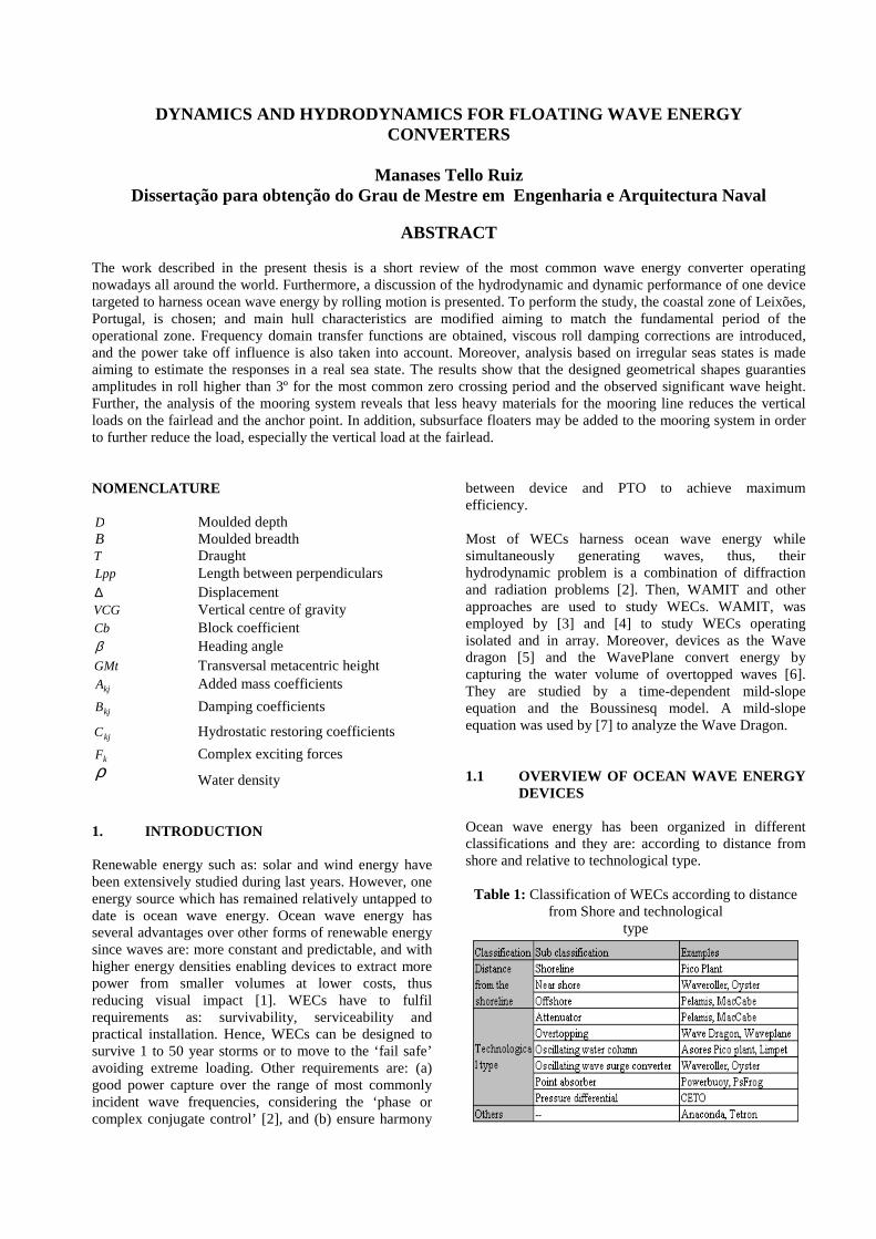
Table 1: Classification of WECs according to distance from Shore and technological
type

Classification according to distance from shoreline are: shoreline, near shore and offshore WECs. On the other hand according to technological type devices can be divided as: attenuators, overtopping, oscillating water column, oscillating wave surge converters, point absorbers and pressure differential. Table 1 presents a classification of the most common devices. 2. THEORY The response of a vessel in a seaway is a complicated phenomenon involving the interactions between the vessel dynamics and several distinct hydrodynamic forces. All responses are nonlinear to some extent but in many cases when nonlinearities are small a linear theory will yield good predictions. In the case of WEC, ignoring interactions between mooring systems and power cables, the floating device during operations can be assumed as free-floating bodies. Therefore, rigid body oscillatory motions are solved in the frequency domain to obtain the six degrees of freedom. This is calculated by solving a set of coupled linear differential equations, which represent the equilibrium:
( ){ }
1,...,6=jk,
e ei6
1
tk
jjkjjkjjkjkj FCBAM ωηηη =+++∑
=
&&& (1)
These excitation forces kF and ship motions jη can be
conveniently represented on a right handed Cartesian coordinate system, ),,( zyxX = , fixed with respect to
the mean position of the vessel and origin in the plane of the undisturbed free surface. As shown in Figure 1, the translatory displacements in the x , y , and z directions
are respectively surge 1η , sway 2η , and heave 3η , while
the rotational displacements about the same axis are respectively roll 4η , pitch 5η , and yaw 6η , where
subscripts, jk, indicate forces in the k -direction due to
motions in the j -mode. kjM are the components of the
mass matrix for the ship, kjA and kjB are the added mass
and damping coefficients, kjC are the hydrostatic
restoring coefficients and kF are the complex amplitudes
of the exciting forces.
Figure 1: Coordinate system and six modes of motion,
and definition of the vessel heading angle.
This investigation uses WAMIT software to calculate the potential flow hydrodynamic coefficients and harmonic wave exciting forces. The equations of motion are solved in the frequency domain to obtain response amplitude operator (RAO) for the floating structure. WAMIT is based on the linear and second-order potential theory for analyzing floating or submerged bodies, in the presence of ocean waves. The panel method is used to solve for the velocity potential and fluid pressure on the submerged surfaces of the bodies. WAMIT evaluates separate solutions for the diffraction and the radiation problems for each of the prescribed modes of motion. Then the relevant hydrodynamic parameters including added-mass and damping coefficients, exciting forces, RAOs, the pressure and fluid velocity, and the mean drift forces and moments. More details can be found in WAMIT user manual [8], while the theoretical formulation for derived responses can be found in [9]. 3. A WEC BASED ON ENERGY CAPTURE
BY ROLL MOTION The study of the hydrodynamics and dynamics for a floating WEC harnessing ocean wave energy by rolling motion is presented. The WEC is assumed to operate in the coastal zone of Leixões, Portugal. To maximize energy capture hullforms have to accomplish: • The resonance period should meet the most common
period in the Portuguese coastal area of Leixões, which is around 5-9 [s] (74.33 % of the registered waves). For the purpose of the study a period of T≈7.5 [s] has been chosen in order to aid to a better understanding of the main hull parameters.
• The C.G. should be placed to the centre of the waterplane determined by the waterline (hereafter waterplane), this because major space for the PTO and major facility of installation on board. Moreover, this will simplify the moments applied to the PTO since it is a rotational converter and not translational.
• The need of a small metacentric height (GMt), in order to have less restoring moments, contributing to the incensement of the roll angle at periods even different than the resonance period.
• In addition, it is also important to consider the heave performance in order to avoid higher acceleration in the vertical direction, this considering the device when will be tow to the operational area.
3.1. Influence of the Hullform in Roll Motion Roll motion is related to hull parameters by: (a) the waterplane area, (b) hullform, (c) the vertical centre buoyancy and (d) the vertical centre of gravity. However, the analysis is only carried out for items a, b, and c, while the centre of gravity is hold at the water plane area.

To match the resonance period it can also be done by adding a mass sprig system well-known as latching control. However, the present work pretends to find the enhancement hullform to further work apply control. To understand the behavior of the hullform in roll motion, different geometries were analyzed. From the analysis, it is observed that the elliptical shape has smaller percentage of the added moment of inertia followed by the triangular and the rectangular shape (see Table 2). The advantage of this smaller added moment of inertia can be seen when comparison between the elliptical and the triangular geometry are made. In this case, the smaller amount of added mass experienced by the elliptical shape explains why the elliptical design has smaller resonance period even when both have approximately the same GMt. When comparing to the rectangular design the advantage of the elliptical geometry is more evident, this since the rectangular shape needs smaller GMt values and larger displacements to match the same resonance period and this can only be achievable by moving the centre of gravity or increasing the displacement which is impractical ( 96.0=bC ). Therefore, the future discussion
is focused on the triangular and the elliptical shape. In Fig. 3, roll motions are plotted for the elliptical and the triangular design. It can be observed that resonance roll period for the triangular shape is 7.75 [s] with amplitude of 5.7° [deg/m] and the elliptical shape experience a resonance period of 7.5 [s] with roll amplitude of 12.5° [deg/m]. It also seen that the roll amplitudes for the elliptical is bigger than experience for the triangular geometry for a wave period ranging from 4 [s] till 11 [s] for quartering bow and bean seas. This variation can be understood from the exciting moment applied to the floating structure. This is shown in Figure 2. Figure 2 shows how the exciting roll moment vary respect to the cross sections of the floating structure, thus
for a rectangular section the moments are due to (1+2+3), for the round section (2+3) and for the V section the exciting moment is only due to (3).
Figure 2: Exciting moment on the vessel hull
Then to maximize energy production and match the resonance period of Leixões, the floating devices should math the following requirements: • A relative cross sectional area closer to the waterline in
order to increase the exciting moment. • A small second moment of area and therefore a small
hull displacement in order to keep the same resonance period with smaller GMt values, which will guaranty bigger roll motions for wave frequencies different than the resonance.
• The elliptical shape seems to be a best choice since the roll motion is bigger compared to the triangular shape. The small percentage of added moment of inertia permits to match the resonance period at smaller GM values, and the bigger cross sectional area, closer to the waterplane, increases the exciting moment. Its slenderness also important since it decreases heave motion avoiding vertical movements and therefore improving the operability of the device (see Fig. 3).
Table 2: Main hull parameters and hydrodynamic coefficients for the triangular, elliptical and rectangular geometries
Figure 3: Heave and roll motion for the triangular and the elliptical geometries in following, beam and bow quartering
waves, respectively.

3.2. Hullform Analysis Including the PTO System Considering what has been stated before, the next steep is to modify the hull shape enhancing its performance for roll motion. In this section, modelling of the PTO and its influences in roll motion is considered for a floating structure carrying multiple and a single PTO. Manny WECs have been proposed and a remarkable example is the work of [3] where a device harnessing wave energy by pitch motion, is presented. This motivates to study a device harnessing ocean energy by roll motion since it experiences bigger amplitudes than the pitch motion. To accomplish this work, the physical model of an apparatus for gyroscope propulsion is considered (see US patent No US 6,705,174 B2), Thus according to its physical model; the PTO can be addressed similar to the mechanical principle of the well know gyroscopic stabilizer. Which according to [10] this type of establishers are very effective and can reduce around to 60% to 80% of the roll motion but were left for reduction of roll motion due to large spare requirements. The moment, zM , comes from the conservation of
angular moment and is given by:
4ηω &rzz IM = (2)
Where zI is the mass moment of inertia of the spinning
element about the axis of spin, rω is the angular velocity
of spin, and 4η& the velocity of rolling motion.
Figure 4 plots the RAO for roll motion for a given hull geometry with and without the influence of the PTO. It can be observed that a significant reduction of the roll amplitude when applying the PTO.
Figure 4: Roll motion in bow quartering and beam
waves, with the PTO, considering rzI ω = 2.0 k and 30k
[ ]radNms /
Table 3: Main hull parameters and hydrodynamic coefficients of OPTMAL01 geometry
Figure 5: Heave and roll motion for OPTMAL01 geometry in following, beam and bow quartering waves, respectively,
and a profile view of elliptical geometry

3.2.1. Hullform Analysis for Three Spheres The hullform designed here is namely OPTMAL01. This is designed with a waterplane area as a result of modification of the elliptical shape (less breadth at the fore and aft) with length of 12[m], beam 4.5[m] and draught 1.8[m]. Main hull parameters and the hydrodynamic coefficients are presented in Table 3, while a perspective view is show in Fig. 5. Moreover, a rounded shapes (with nearly elliptical water plane areas) has been chose for the design. This since the contribution of viscous damping and other damping sources to the total roll damping are less, therefore their effects are less influents in rolling motion and consequently also increases roll amplitudes. Other advantage of the rounded shape is the smaller values of the block coefficient adding to match the required resonance period at smaller GMt. OPTMAl01 has been analyzed with WAMIT considering an external damping of 30k [N-m-s] for the three spherical PTOs. Viscous damping factor of 0.07 has been taken from the experimental work of [11]. RAOs are presented in Fig. 5 for heave, pitch and roll motion. Table 3 presents the hydrodynamic coefficients for the proposed design. It is seen that it experiences smaller amount of added moment of inertia, and this is even less
than the obtained for the elliptical geometry (see Table 3 and 2). The reason of this hydrodynamic behaviour is mainly due to the rounded shape of OPTMAL01 From Fig. 5, it can be seen that the RAO for heave motions is less than 1 for all wave periods. Hence, the device will not experience higher vertical motion. This is convenient when the device will be towed and since it also has to be moored, therefore, simplifying the stationkeeping requirements and design for the WEC. In Figure 5 also plots for the RAO for the pitch motion is presented. This shows that the device experiences bigger pitch amplitude which could limit the operation of the device, however this does not represent bigger problems since the resonance for pitch is around 4 [s] which is normally associated to small waves amplitudes. In the case of roll the proposed geometry presents a broader shape for bow quartering and beam waves. This can be explained due to its relative smaller GMt achieved for this geometry which a result of the smaller xxI and
the smaller vessel displacement, consequently decreasing the GMt. However, any change of GMt vary the resonance period, but it does not happen for OPTMAL01 due to the rounded cross sections which has small added moment of inertial permitting to hold the resonance period at even smaller values of GMt (see Table 3)
Table 4: Main hull and hydrodynamic parameters UFO02 and the sphere
Figure 6: Heave and roll motion for UFO02 and the sphere geometries in following, beam and bow quartering waves,
respectively, and a profile view of geometries.
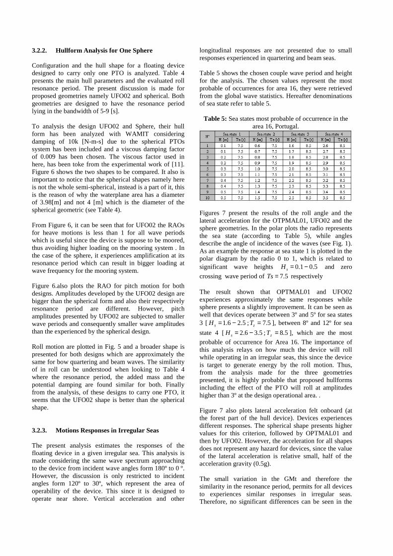
3.2.2. Hullform Analysis for One Sphere Configuration and the hull shape for a floating device designed to carry only one PTO is analyzed. Table 4 presents the main hull parameters and the evaluated roll resonance period. The present discussion is made for proposed geometries namely UFO02 and spherical. Both geometries are designed to have the resonance period lying in the bandwidth of 5-9 [s]. To analysis the design UFO02 and Sphere, their hull form has been analyzed with WAMIT considering damping of 10k [N-m-s] due to the spherical PTOs system has been included and a viscous damping factor of 0.009 has been chosen. The viscous factor used in here, has been toke from the experimental work of [11]. Figure 6 shows the two shapes to be compared. It also is important to notice that the spherical shapes namely here is not the whole semi-spherical, instead is a part of it, this is the reason of why the waterplane area has a diameter of 3.98[m] and not 4 [m] which is the diameter of the spherical geometric (see Table 4). From Figure 6, it can be seen that for UFO02 the RAOs for heave motions is less than 1 for all wave periods which is useful since the device is suppose to be moored, thus avoiding higher loading on the mooring system . In the case of the sphere, it experiences amplification at its resonance period which can result in bigger loading at wave frequency for the mooring system. Figure 6.also plots the RAO for pitch motion for both designs. Amplitudes developed by the UFO02 design are bigger than the spherical form and also their respectively resonance period are different. However, pitch amplitudes presented by UFO02 are subjected to smaller wave periods and consequently smaller wave amplitudes than the experienced by the spherical design. Roll motion are plotted in Fig. 5 and a broader shape is presented for both designs which are approximately the same for bow quartering and beam waves. The similarity of in roll can be understood when looking to Table 4 where the resonance period, the added mass and the potential damping are found similar for both. Finally from the analysis, of these designs to carry one PTO, it seems that the UFO02 shape is better than the spherical shape. 3.2.3. Motions Responses in Irregular Seas The present analysis estimates the responses of the floating device in a given irregular sea. This analysis is made considering the same wave spectrum approaching to the device from incident wave angles form 180º to 0 º. However, the discussion is only restricted to incident angles form 120º to 30º, which represent the area of operability of the device. This since it is designed to operate near shore. Vertical acceleration and other
longitudinal responses are not presented due to small responses experienced in quartering and beam seas. Table 5 shows the chosen couple wave period and height for the analysis. The chosen values represent the most probable of occurrences for area 16, they were retrieved from the global wave statistics. Hereafter denominations of sea state refer to table 5.
Table 5: Sea states most probable of occurrence in the area 16, Portugal.
Figures 7 present the results of the roll angle and the lateral acceleration for the OTPMAL01, UFO02 and the sphere geometries. In the polar plots the radio represents the sea state (according to Table 5), while angles describe the angle of incidence of the waves (see Fig. 1). As an example the response at sea state 1 is plotted in the polar diagram by the radio 0 to 1, which is related to significant wave heights 5.01.0 −=sH and zero
crossing wave period of 5.7=Ts respectively The result shown that OPTMAL01 and UFO02 experiences approximately the same responses while sphere presents a slightly improvement. It can be seen as well that devices operate between 3º and 5º for sea states 3 [ 5.26.1 −=sH ; 5.7=zT ], between 8º and 12º for sea
state 4 [ 5.36.2 −=sH ; 5.8=zT ], which are the most
probable of occurrence for Area 16. The importance of this analysis relays on how much the device will roll while operating in an irregular seas, this since the device is target to generate energy by the roll motion. Thus, from the analysis made for the three geometries presented, it is highly probable that proposed hullforms including the effect of the PTO will roll at amplitudes higher than 3º at the design operational area. . Figure 7 also plots lateral acceleration felt onboard (at the forest part of the hull device). Devices experiences different responses. The spherical shape presents higher values for this criterion, followed by OPTMAL01 and then by UFO02. However, the acceleration for all shapes does not represent any hazard for devices, since the value of the lateral acceleration is relative small, half of the acceleration gravity (0.5g). The small variation in the GMt and therefore the similarity in the resonance period, permits for all devices to experiences similar responses in irregular seas. Therefore, no significant differences can be seen in the

performance of these hull shapes. However, the lateral acceleration can be used as a selecting criterion when we
look for the best configuration and hull shape form. Also, the ratio cost and energy production can be used.
Figure 7: Motion in roll and lateral accelerations calculated at the bow for the geometries OPTMAL01, UFO02 and
sphere. The first three polar plots belongs to roll motion while the remaining to lateral acceleration
3.3. Mooring Line Analysis Mooring lines are subject to environmental forces such as: wind, current, tidal and ocean waves. Wind as well current forces might be divided into mean and fluctuation forces, and vortex induced vibrations. While wave forces can be divided into components as: The 1st order forces at wave frequencies (WF); 2nd order forces and higher order forces. 2nd order forces comprises mean wave drift forces, forces at sum frequencies (HF) and forces at lower frequencies (LF), while higher order forces comprises wetted surface effects, ringing and viscous (non-potential). Those environmental forces are considered according to the analysis proposed. Generally, the analysis of mooring cables is divided in two stages: during pretension and in service. When the cable is addressed during pretension a static analysis can be performed neglecting the environmental factors (such as current and wind when the mooring cable is considered a heavy cable). While
when analysis is made in service, different approach can be used to solve the dynamic and hydrodynamic problem. Mooring lines can be built of all chain, wire rope, chain/wire rope combination or synthetic mooring lines. Other components can be used as a clump weight, spring buoy. Clump weights improve the performance and reduce costs. They provide concentrated weight at the point close to the seabed thus replacing a portion of chain and increasing the restoring force of the mooring leg. While spring buoys can be applied to reduce weight of mooring lines that must be supported by the vessel hull, reduce effects of line dynamics in deep water and reduce vessel offset for a given line size an pretension Anchor systems are available in a variety, some of the most common are: drag embedment anchors, pile anchors (driven, jetted, drilled and grouted), caisson foundations (suction anchors), gravity anchors and propeller embedment anchors
Figure 8: Coordinate systems and forces action on the cable [12]

The forces acting on the cable segments (see Fig. 8) in water are: the tension: µrT− and ( )( )µµ rr
ddTT ++ ;
effective weight; kdlGw
r− ; tangential drag
force; µrr
FdlF = ; normal drag force; νrr
HdlH = and
the binormal drag force; ωrr
QdlQ = . where T is the
tension along the cable, wG is the effective weight per
unit length in water, ,, HF and Q are the tangential,
normal and binormal drag forces caused by ocean currents per unit length, respectively. The equilibrium of a cable suspended in water results in the following differential equations:
FGdl
dTw −= αsin (3)
α
θcosT
H
dl
d = (4)
( )QGTdl
dw −= αα
cos1
(5)
The tangential, normal and binormal drag forces per unit length in water can be acquired through Morison’s equation [13]. Moreover the cconstitutive relation of the mooring cable is assumed to be continuous and extensible with a linear elastic stress–strain relationship given by Hooke’s Law:
−== 1....
0dl
dlAEAET ε (6)
where E is the Young’s Modulus, A the cross-sectional area of the unstrained cable, ε is the unit elongation and l0 is the unstrained cable length. Under axial tension the unit effective weights of cable in water, wG and the cross-sectional area A , must be
modified as ( )ε+= 1// 00 AGG ww ( )ε+= 1/0AA .
3.3.1. Numerical Model Herein the mooring line is analyzed during pretension to determinate its influence and to select the best suitable for the WEC, this from a static point of view. Discussion of designs, by means of: one or two systems, different mooring radius and cables properties, and the use of buoys for water depth of 50 [m]. When pretension analysis is consider, a static approach is chosen to study the mooring problem. In this process, the mooring cable is discretized inton segments with the same nDdy /= , where D is the anchoring radius
in the horizontal direction and n is the segment division number of the mooring cable.
The end point of each segment is numbered by the indexi , which runs from 1 at beginning of the system till 1+n at the end of the system. The coordinate of the anchor point ( )11, zx is assumed to be( )0,0 . Here, the
following parameters should be known prior to calculation: design pretension load 1+nT ; water depth
H ; anchor point; anchoring radius D ; cable properties, including Young’s modulus E , cross-sectional area 0A , unit effective weight of cable in
water 0wG ; and buoyancy force and position, if buoy is
applied. It can be known that the coordinate of the top point ( )11, ++ nn zx is equal to( )HD, . This analysis
considers heavy mooring cables therefore drag forces are neglect. The iterative equations are: iwiii dliGTT αsin1 −= + (7)
( )iwii
ii GT
dli ααα cos1 −= + (8)
iwiiiw dlGdlG =00 (9)
( )iii EATi 0/=ε (10)
The cable is discretized with the same nDdy /= , so the
length of strained segment is:
+= +
2cos/ 1ii
i dydlαα
(11)
Other option to obtain the unstrained segment is from Equation. 10:
( )iii dldl ε+= 1/0 (12)
The geometry equations of the strained cable are:
iiii
iiii
dlzz
dlxx
αα
sin
cos
1
1
−=−=
+
+ (13)
With the given coordinate( )11, ++ nn zx , the iterative
procedure can be initiated with an assumed elevation angle at the top point 1+nα as the ( )DH /arctan . Fig. 9
shows that in each iterative step, the calculated coordinate of the anchor point ),( 11 zx should be
compared with the real anchor point ( )0,0 to see if the
error ( ) 2/121
211
~~ zxE += is greater than1δ , where 1δ is a
specified small quantity. If 11 δ>E , 1+nα needs to be
actualized and the running process star again until 11 δ≤E . When to cables are used the analysis is
run till tension at the joint present a difference less than 10%, this save larger computational time.

3.3.2. Analysis of Mooring Line Configurations The analysis if divided in eight combinations. Table 6 presents deign configuration chosen for mooring line. The studies are namely mooring 1 till mooring 8 and only mooring 2 is design with one system. The study also considers two types of material, a chain with
[ ]mkNGw /.86.20 = , [ ]kNxEA .6^10997.120 = and
[ ]kNxBS .4^105.1= ; and steel wire: [ ]mkNGw /.814.00 =
[ ]kNxEA .3^10150.10 = and [ ]kNxBS .4^106.1= , where
0wG is the weight per unit length in water EA0 the
stiffness and BS the breaking strength. To study the influence when some parameters are vary, the design of the mooring lines are grouped, the classification can be seen in table 7. Figure 9, shows the two dimensional profile of the mooring design for a disposition of two cables joined at the point where buoyancy is applied. System 1 is defined between the fairlead and the anchor point for a mooring composed by only one cable. When two systems are used, system 1 lies between the fairlead and the joint, consequently system 2 does between the joint and the anchor point.
Figure 9: Two dimensional profile view of mooring
Design requirements mooring 1,3-8 have been considered. These requirements are: the same profile for system 1 (only valid in each group of analysis) and designed to transmit the same horizontal tension in all configurations conformed by two systems. Finally a less vertical tension is considered as a selecting criterion. The study for groups 2, 3, 4 and mooring 2 in group 1 should be designed with anchor which can support vertical tension at the anchor, while only mooring 1 presents less vertical tension thus drag anchor could be suitable for this configuration. However, design requirements as the restriction in space is important to consider, this since many devices will be places operating simultaneously. Considering less footprint area, a comparison of mooring 1 and mooring 3 shows that for 40 [m] of mooring radius, mooring 3 does not present any bigger increment on the vertical tension applied in the anchor, however the opposite holds true
when a reduction to 30 is made for mooring 4 (chain material for both system 2).
Table 6: Mooring lines characteristics for each design.
From Table 6, it is observed that requirements of buoyancy increases as the mooring radio decreases. in group 2 (chain material for both system 2) When steel wire is used a considerable reduction of the buoyancy is found for mooring 6 in group 3, and this can be confirm when comparison between mooring 7 and mooring 8 in group 4 is made. The results for mooring 1 and mooring 5 present that when the buoy is located and deeper positions (for mooring 5) less buoyancy is needed.
Table 7: Mooring line tensions and characteristics
Finally form the analysis made in group 1, needs of including a buoy is pointed out this since considerable reduction of the vertical load is observed and the importance of considering materials with less weight since it decreases loads from the mooring into WECs. Less heavy materials are also needed due to the

reduction of the net buoyancy required (see Table 6). It is important to point out that there might be an extra loading on the mooring due to the buoy at motion at wave frequencies, thus the depth at which the buoy will be placed should be studied 4. CONCLUSIONS A large variety of WECs are found in the literature, which is classified in different form. However, the classification of WECs according to the technological type appear sto be one of the most useful as it permits to compare a broad range of devices at a certain stage. From the analysis made for a WEC harnessing ocean energy by roll motion the following were found: the resonance period and the amplitudes of roll motions are dependent of the metacentric height, added moment of inertia and the structural inertia of the floating structure. The analysis shows that waterplane with a geometrical form closer to an ellipse gives less second moments of area and consequently helps to decrease the GMt of the floating structure. Small GMt is needed when aiming to match the resonance period, since it helps to maximize roll motion periods other than the resonance, thus increasing energy production. Considering all stated above, three geometries were proposed and analyzed with WAMIT taking into account the effects of the PTO. RAOs were obtained and no significant variation was observed in roll motion. Furthermore, an analyzed in irregular seas were perform, and from results roll motion higher than 3º for most of the commonly observed significant wave heights and zero crossing wave periods were found. Moreover smaller accelerations were observed which is important for the performance of the device. The analysis shows the importance of the main hull characteristics for a WEC aiming to harness ocean by oscillation motions. The geometrical characteristics of the floating device determine the behaviour of the structure at sea and consequently delimit the efficiency of the device in terms of energy extraction and conversion. It is also important to mention that the device must be designed for a range of periods and not only for the resonance period in order to enhance its overall performance. Hence, it is required to count with small GMt values, since it helps to decrease the restoring moment and consequently maximizes rolling motion thus energy extraction.. In addition, a set of proposed mooring designs were studied. The analysis reveals the relevance of using less heavy materials for the mooring cable and the importance of buoyancy of to reduce vertical loads at the fairlead. Moreover, significant reduction of the vertical load at the fairlead was found when varying the mooring radio,
5. REFERENCES [1] Brekken, T. K.A., Von Jouanne, A., Han, H. Y.,
(2009), “Ocean Wave Energy Overview and Research at Oregon State University”, Power Electronics and Machines in Wind Applications, 2009. PEMWA 2009. IEEE , vol., no., pp.1-7.
[2] Budal, K. and Falnes, J., (1980), “Interacting Point Absorbers With Controlled Motion. Power from Sea Waves”, In: Power from Sea Waves (B. Count, ed.), pp. 381-399. Academic Press, London.
[3] Buchner, B., (2010), “Model Tests and Simulations on a Wave Energy Converter Based on Inverse Offshore Engineering”, Offshore Technology Conference, May 3-6, Houston, Texas, USA.
[4] Whittaker, T., Folley, M., (2005), “Optimisation of Wave Power Devices Towards Economic Wave Power Systems,” World Renewable Energy Congress, Aberdeen, UK.
[5] Kofoed, JP., Frigaard, P., Friis-Madsen, E., Sørensen, HC., (2006), “Prototype Testing of the Wave Energy Converter Wave Dragon”, Renewable Energy , pp. 31:181–9.
[6] Beels, C., Troch, P., De Backer, G., Vantorre, M., De Rouck, J., (2010), “Numerical Implementation And Sensitivity Analysis Of A Wave Energy Converter In A Time-Dependent Mild-Slope Equation Model”, Coastal Engineering, Volume 57, Issue 5, May, pp. 471-492.
[7] Beels, C., Troch, P., De Visch, K., Kofoed, J. P., De Backer, G., (2010), “Application Of The Time-Dependent Mild-Slope Equations For The Simulation Of Wake Effects In The Lee Of A Farm Of Wave Dragon Wave Energy Converters”, Renewable Energy, Volume 35, Issue 8, August, pp. 1644-1661.
[8] WAMIT User Manual Version 6.4, 6.4PC and 6.1S, 6.1S-PC, WAMIT Inc., www.wamit.com.
[9] Tello, M, Ribeiro e Silva, Guedes Soares, C., “Fishing Vessels Responses in Waves under Operational Conditions” XXI Pan American Congress of Naval Engineering,, Uruguay, 2009.
[10] Bhattacharya, R., (1978), “Dynamics of Marine Vehicles”, A Wiley Interscience Publication.
[11] Pessoa, J., Fonseca, N., and Guedes Soares, C., (2010), “Experimental And Numerical Study Of The Depth Effect On The First Order And Slowly Varying Motions Of A Floating Body In Bichromatic Waves”, Proceedings of the ASME 29th International Conference in Offshore Mechanics and Arctic Engineering, OMAE2010, Shanghai, China, June 6-11.
[12] Wang, L., Guo, Z., Yuan, F., (2010), “Quasi-Static Three-Dimensional Analysis of Suction Anchor Mooring System”, Ocean Engineering, Volume 37, Issue 13, September, Pages 1127-1138.
[13] Morison, J.R., O’Brien, M.P., Johnson , J.W., and Schaaf, S.A., (1950), “The Force Exerted by Surface Waves on Piles”, Petroleum Transactions 189 (1950), pp. 149–157.