response to the beyond einstein program assessment committee
TRANSCRIPT

1
Response to the Beyond Einstein Program Assessment Committee (BEPAC) Request for Information
Einstein Inflation Probe
Experimental Probe of Inflationary Cosmology (EPIC) Mission Study
Study Team Leader: James Bock Senior Research Scientist, Jet Propulsion Laboratory Visiting Associate, California Institute of Technology
22 January 2007

2
Request for Information NRC Beyond Einstein Program Assessment Committee
Instructions for Responding The panel requests that mission teams respond to the following questions as completely as possible. However, we fully recognize that the missions are at different stages of definition, and answers may not be available for many of the more detailed questions. For example, a specific spacecraft implementation may not have been selected, and so many details cannot be provided. In this case it is sufficient for the panel to understand the overall spacecraft complexity and requirements. We have attempted to indicate below where details are optional. We also request that you please ensure that any written responses or diagrams that you include do not include ITAR-controlled information. The NRC will consider your response as public information and available to the public, if requested.
Science and Instrumentation
Describe the scientific objectives and the measurements required to fulfill these objectives The scientific objectives for the Experimental Probe of Inflationary Cosmology (EPIC), and measurements required to fulfill them are given in the second and third columns of Table 1 below. The first column puts the scientific objectives in the context of NASA's objectives, and the fourth column gives the instrument criteria that follow from the necessary measurements. The table is split vertically to the primary science objectives (pink) and to secondary science themes (green), which may be achievable by EPIC but do not drive the design of the instrument. We adopt parameters for the instrument based on the NSF/NASA/DOE Weiss committee report (Task Force for Cosmic Microwave Background Research, astro-ph 0604101) where applicable. The scientific objective of detecting the CMB polarization BB power spectrum at a level of r = 0.01 after foreground removal are also shown in Fig. 1.

3
Table 1. EPIC Science Objectives and Measurements
NASA Objective EPIC Objective Measurement Criteria
Instrument Criteria
wp−1/2 < 6 μK-arcmin†
30 – 300 GHz† Detect BB signal at
r = 0.01* after foreground removal Control systematics
to negligible levels All-sky coverage
Discover what powered the Big Bang… search for gravitational
waves from the earliest moments of the Big Bang
Discover the origin, structure, evolution, and destiny of the
universe (NASA 2006 Strategic Plan)
Test Inflationary paradigm at GUT
energy scales by probing Inflationary
Gravitational Wave B-mode polarization signal
to r = 0.01. Positively detect
both the ℓ = 5 and ℓ = 100 BB peaks
Low angular resolution (< 1˚)†
Understand how the first stars and galaxies formed
Determine the size, shape, and matter-energy content of the
Universe
Distinguish models of reionization
history
Extract all available EE cosmology
Measure EE to cosmic variance
Measure lensing BB to determine neutrino mass
and dark energy equation of state
Measure the cosmic evolution of the dark energy, which controls the
destiny of the universe Remove lensing BB using shear map
Measure lensing BB to ~cosmic variance
…Trace the flows of energy and magnetic fields… between stars,
dust, and gas
Map Galactic magnetic fields
Measure synchrotron and dust polarization
Parameters above
Primary Objective
Secondary Objective
†Parameters recommended by Weiss Committee TFCR

4
Fig. 1. The sensitivity of EPIC, WMAP and Planck to CMB polarization anisotropies. E-mode polarization anisotropies from scalar perturbations are shown in red, B-mode from tensor perturbations are shown in blue for r = 0.3 and r = 0.01, and B-mode polarization produced by lensing of the E-mode polarization is shown in green. The science goal of EPIC is to reach the level of r = 0.01 for the multipole range ℓ < 100 after foreground subtraction. Expected B-mode foreground power spectra for polarized dust (orange solid) and synchrotron (orange dashed) at 100 GHz are determined by power-law models fits to the foreground power in a combination of WMAP 23 GHz polarization maps (Page et al. 2006), Haslam et al. 1981 low frequency radio maps, and Finkbeiner, Davis, and Schlegel (1999) 100 micron dust map for |b| > 20˚. The sensitivity of EPIC is given over a range from the required baseline sensitivity (top of the gray band) and a 1-year mission to the design TES-option sensitivity and a 2-year mission (bottom of the gray band). Note these curves show raw band-combined sensitivities and do not show sensitivity including foreground removal. Describe the technical implementation you have selected, and how it performs the required measurements. EPIC is designed based on the instrument criteria in Table 1. The architecture for the instrument is shown in Figure 2. We have chosen a technical implementation based on high technology readiness level (TRL). The EPIC instrument consists of 6 imaging polarimeters operating at frequencies between 30 and 300 GHz. Each polarimeter consists of a refracting 30-cm telescope assembly with two lenses made from high-density polyethylene, a stepped half wave plate made from sapphire, a focal plane array, and thermal blocking filters. The waveplate is placed in front of the telescope optics. The telescopes and waveplates are cooled to 2 K inside a 450-liter liquid helium cryostat.

5
The six focal plane arrays are cooled to 100 mK by a single-shot adiabatic demagnetization refrigerator (ADR). The focal planes consist of polarization sensitive antenna-coupled bolometers read out with neutron-transmutation-doped (NTD) Ge thermistors with cooled JFET read outs mount to the 40 K passively-cooled stage. The thermistors and read out electronics are identical to the technologies developed for the ESA/NASA Planck and Herschel satellites. The cryostat is passively cooled by a 3-stage V-groove radiator such that the shell of the cryostat cools to 40 K. The cryostat, radiator, and sunshield are mounted to a commercial 3-axis zero-momentum spacecraft bus. The radiator consists of 3 rigid sections which provide staged cooling of the bipod supports and wiring. A 3-stage deployed sunshield extends the rigid sections of the radiator to protect the optics and cryostat shell from sunlight and thermal re-radiation. The deployed sunshields are assumed to have zero thermal conductivity and thus not cool the cryostat supports and wiring. A low-gain toroidal-beam antenna is mounted on the back of the spacecraft for downlink.
Fig. 2. The EPIC instrument consists of 6 imaging polarimeters. The detailed design for one of the polarimeters is shown in Fig. 5. The telescopes are cooled to 2 K inside a liquid helium cryostat. Bolometric detectors at the focal plane are maintained at a temperature of 100 mK. The cryostat and radiators are mounted to a commercial spacecraft bus through bipods.

6
The instrument performs the measurements with a single spinning and precessing scan strategy throughout the entire mission life. We optimized the scan strategy for discrimination against polarimetric systematic errors by ensuring that the instrument viewing angle completely rotates relative to each patch of the sky; see Figure 4. The scan strategy also produces redundant daily maps covering more than 50 % of the sky for systematic error mitigation. Finally the same pattern makes maximum use of passive cooling, so that the cryostat shell operates at ~40 K, without ever changing the solar power input to the back of the spacecraft, for maximum thermal stability.
Fig. 3. Schematic of the observing strategy at L2. The instrument rotates about the spin axis at 1 rpm to scan each of the 6 telescope beams on circles on the sky. The optical axis of each telescope is offset from the spin axis by 55˚. The spin axis is set at 45˚ from the sun-spacecraft axis and precesses about the sun-spacecraft axis at 1 rph. This strategy keeps fixed the thermal input power from the sun onto the back of the spacecraft, to maintain high thermal stability. The observation strategy produces a complete map of half the sky in several precession cycles, depending on the exact choice of angles and rates chosen. Over the course of 6 months, as the spacecraft orbits the sun, a complete sky map is produced which has nearly ideal properties for polarimetry, rotating the view of each telescope through a large range of angles on each region of the sky with uniform coverage in angle and integration time. A fixed antenna with a low-gain toroidal beam pattern allows for data downlink to Earth without interrupting the scan pattern. The deployed sunshield and baffles are designed to keep radiation from the sun and moon from viewing the instrument.

7
<sin 2β>2 + <cos 2β>2
0 1
Fig. 4. EPIC 6 month sky map. The uniformity in the crossing angle on the sky, <sin 2β>2 + <cos 2β>2, where β is the crossing angle on each pixel of sky, after six months of observing. An ideal polarization experiment would obtain <sin 2β>2 + <cos 2β>2 = 0. The EPIC scan strategy provides nearly perfect angular uniformity. Further information on the scan pattern is shown in Figs. 6 and 7 below. Of the required measurements, which are the most demanding? Why? The prime goal of detecting gravitational-wave polarization shown in Table 1 is the most demanding, and sets all the instrument requirements. A space mission is essential to accomplish this objective by providing 1) all-sky coverage to access the required multipole range, 2) suppression of systematic errors, 3) frequency coverage from 30 - 300 GHz necessary to model and remove foreground emission, and 4) sufficient sensitivity. The secondary science goals describe other themes the instrument will address, but do not set requirements. Present the performance requirements (e.g. spatial and spectral resolution, sensitivity, timing accuracy) and their relation to the science measurements. The performance requirements are given in Table 2 below (middle column). They are related to the instrument criteria (first column), which originate from Table 1. In the third column we give the design goals of the instrument which provide margins of safety relative to the requirements.
Table 2. EPIC Performance Requirements Instrument Criteria Requirements Design Goals
High sensitivity wp−1/2 < 6 μK-arcmin wp
−1/2 < 2 μK-arcmin
Subtract foreground signals to negligible levels
Remove foregrounds to below r = 0.01 science goal
Optimize bands for foreground removal based on best
knowledge
Control systematic errors to negligible levels
Suppress systematic errors to < 10 % of r = 0.01 signal, after
correction
Suppress raw systematic effects to less than 10 % of
statistical noise level Maintain sensitivity on large
angular scales All-sky coverage with redundant interleaved scan strategy
Angular resolution < 1˚ at 100 GHz

8
Describe the proposed science instrumentation, and briefly state the rationale for its selection. EPIC is based on a drift-scanned wide-field imaging refracting telescope, from a design that has been fielded and tested by the BICEP CMB polarization experiment. There are 6 such telescopes on the spacecraft. One EPIC telescope is shown in Figure 5. This telescope provides a wide (~20˚) unabberated field of view with excellent polarization properties. CMB polarization measurements with large degree beams place strict requirements on the symmetry and polarization of the main beams. Measurements of the BICEP telescope indicate that main beam effects are small, but not negligible for a space mission with high sensitivity. For additional systematic error control of these effects, we therefore place a wave plate in front of the telescope optics. The wave plate is stepped once every 24 hours. Because the wave plate rotates the polarization direction without changing the illumination on the pupil, and thus without changing the beam shapes on the sky, it allows us to separate a true polarization signal from any polarization induced by the refracting optics. A half wave plate was already used successfully by the CMB balloon borne experiment MAXIPOL in a continuous rotation mode, which is more technically demanding than the stepped mode we are baselining here. Each telescope is designed for monochromatic operation (except the two extreme bands) so that the lens anti-reflection coatings are optimized for each band. We use an absorbing stop at the primary aperture at 2 K and an absorbing baffle at 40 K to control the edge illumination from the detector antennas. Based on measurements of a similar forebaffle with BICEP, we have determined that coupling to the baffle is small (0.3 %), and that the far-sidelobe response is already controlled to a level that meets EPIC's systematic error requirements. An array of polarization sensitive antenna-coupled bolometers is placed at the focus of the telescope and cooled to 0.1 K by an adiabatic demagnetization refrigerator. The detectors are sized with 2fλ separations. Use of 2 K optics minimizes the instrumental emission and thus maximizes sensitivity. In the primary science bands, 70 - 200 GHz, emission from the 2.75 K CMB is the dominant source of power loading on the detectors. Parameters for the instrument are summarized in Table 3 for two options, the baseline system using developed high-TRL NTD Ge bolometers (Table 3a), and a more capable option using larger arrays of TES bolometers (Table 3b). The TES detector arrays have very similar sensitivities to the NTD Ge detectors per pixel, but provide an overall systems advantage due to larger array formats. Our sensitivity estimates are based on values (optical efficiency, bandwidth, coupling efficiency) that have all been achieved. Required sensitivities contain a factor of √2 sensitivity margin. For our scientific capabilities we assume the baseline required sensitivities. However our system requirements are specified to accommodate the more-capable TES option so that this technology can be utilized when it becomes mature. We compare the parameters of EPIC to those of Planck in Table 5.

9
Fig. 5. Refracting telescope design (1 of 6 such telescopes) using 30 cm optics and a half wave plate cooled to 2 K. The wave plate is placed in front of the telescope, and eliminates any polarization produced by the telescope. We step the wave plate by 22.5˚ every 24 hours. An absorbing aperture stop at 2 K and an absorbing baffle at 40 K are used to control far-sidelobe response. Arrays of polarization-sensitive antenna-coupled bolometric detectors cooled to 100 mK are located at the telecentric focal plane of the telescope.
Table 3a. Detailed Baseline Bands and Sensitivities Baseline: NTD Ge Bolometers Required Sensitivity1 Design Sensitivity2
NET4 [μK√s] NET4 [μK√s] Freq [GHz]
θFWHM [′]
Nbol3
[#] bolo band
wp−1/2
[μK-′]5 δTpix6 [nK] bolo band
wp−1/2
[μK-′]5 δTpix6 [nK]
30 155 8 83 29 90 530 59 21 45 270 40 116 54 73 9.9 30 180 51 7.0 15 90 60 77 128 61 5.4 17 100 43 3.8 8.2 49 90 52 256 53 3.3 10 60 37 2.3 5.0 30
135 34 256 49 3.1 10 56 35 2.2 4.7 28 200 23 64 59 7.3 22 130 41 5.2 11 67 300 16 64 120 15 44 260 82 10 22 130
Total7 830 1.9 5.9 35 1.4 3.0 18

10
Table 3b. Detailed Bands and Sensitivities for TES Option TES Bolometer Option
Required Sensitivity1 Design Sensitivity2 NET4 [μK√s] NET4 [μK√s] Freq
[GHz] θFWHM
[′] Nbol
3 [#]
bolo band wp
−1/2 [μK-′]5
δTpix6 [nK] bolo band
wp−1/2
[μK-′]5 δTpix6 [nK]
30 155 8 80 28 87 520 57 20 44 260 40 116 54 71 9.6 29 180 50 6.8 15 88 60 77 128 60 5.3 16 97 42 3.7 8.1 48 90 52 512 52 2.3 7.0 42 37 1.6 3.5 21
135 34 512 49 2.2 6.6 39 35 1.5 3.3 20 200 23 576 54 2.3 6.9 41 38 1.6 3.5 21 300 16 576 92 3.8 12 70 65 2.7 5.9 35
Total7 2366 1.2 3.6 22 0.8 1.8 11 Notes: 1Sensitivity with √2 noise margin in a 1-year mission 5[8π NETbolo
2/(Tmis Nbol)]1/2(10800/π) 2Calculated sensitivity with 2-year mission life 6Sensitivity δT in a 120′ x 120′ pixel 3Two bolometers per focal plane pixel 7Combining all bands together 4Sensitivity of one bolometer in a focal plane pixel
Table 4. Sensitivity Model Input Assumptions Optics temperature Topt 2 K Focal plane temperature T0 100 mK Optics coupling* εopt 10 % Optical efficiency* η 40 % Wave plate temperature Twp 2 K Fractional bandwidth* Δν/ν 30 % Wave plate coupling* εwp 2 % NTD Ge heat capacity* C0 0.25 pW/K Baffle temperature Tbaf 40 K NTD time constant† τ(dθ/dt)/θF ≤ 1/2π Baffle coupling* εbaf 0.3 % TES safety factor† Psat/Q 5
*Parameter based on experimental measurement †Selectable design parameter, θF is FWHM
Table 5. Comparison of EPIC and Planck Sensitivity wp-1/2
EPIC Baseline EPIC TES Option Planck1 Freq [GHz] Req'd Design Req'd Design Goal
30 90 45 87 44 350 40 30 15 29 15 350 60 17 8.2 16 8.1 350 90 10 5.0 7.0 3.5 100
135 10 4.7 6.6 3.3 80 200 22 11 6.9 3.5 130 300 44 22 12 5.9 400
Total2 5.9 3.0 3.6 1.8 54 1Planck combined sensitivities in polarization for 1.2 year mission lifetime. Planck bands are shifted slightly to match the closest EPIC band. 2Total wp
-1/2 is combined wp-1/2 from all bands in μK-arcmin
For each performance requirement, present as quantitatively as possible the sensitivity of your science goals to achieving the requirement. For example, if you fail to meet a key requirement, what will the impact be on achievement of your science objectives?

11
Below in Table 6a we describe the risks to the scientific requirements and the approaches we have taken to mitigate risks to the principal instrument criteria, derived from science requirements in Table 1 above. More detailed mitigations that are associated with the fundamental architecture of the instrument are compiled in Table 6b.
Table 6a. Scientific Risk Assessment
Instrument Criteria Requirement
Impact of Not Meeting
Requirement Mitigations
Sensitivity wp−1/2 < 6 μK-arcmin - NET has 1.4x margin
- Lifetime has 2x margin
Foreground subtraction
Remove foregrounds to below r = 0.01
science goal
- Limited subtraction needed in clean regions
- Wide band coverage, flexible band weighting
Systematic error control
Suppress systematic errors to < 10 % of
r = 0.01 signal, after correction
Sensitivity to r decreases - Multiple levels of polarization signal
modulation - Wave plate in front of telescope - Temperature control - High mapping redundancy to assess
systematic error contributions
Mapping large angular scales
All-sky coverage with redundant interleaved scan
strategy
Sensitivity at low ℓ reduced
- Similar scanning technique already demonstrated for WMAP
Angular resolution < 1˚ at 100 GHz Sensitivity at
high ℓ reduced - Chosen by design
Table 6b. Detailed Risk Reduction Strategy
Instrument Requirement Risk Approach Risk Mitigations
Sensitivity NTD Ge detectors Heritage from Planck & Herschel Requirement includes √2 noise margin Up scope to TES bolometers when mature
Subtract foreground
signals below r = 0.01 Antenna-coupled bolometers Single technology covers 30 – 300 GHz
Spinning/precessing scans Uniform angular coverage on the entire sky
Highly redundant scans
Redundant daily maps cover > 50 % of sky to allow comprehensive jackknife tests.
Immunity to data interruptions, bad pixels, bad arrays
Two full maps in 1-year for systematic error testing
Suppress systematic
errors to < 10 % of r = 0.01 signal, after correction
Dual-polarization detector Suppresses common-mode temperature signals, thermal drifts

12
Wave plate modulator in front of telescope
Suppresses main beam systematics by modulating polarization without altering beam shapes
Suppresses 1/f noise, gain and temperature drifts by signal modulation if continuous
Monochromatic refracting telescope
Low instrument- and cross- polarization Low main beam asymmetries Optimized low-reflection coatings Low far-sidelobe response
All-sky coverage 1-year required lifetime Cryostat lifetime at L2 has > 100 % margin
30 cm refracting telescope Polyethylene lenses, simple AR coatings Demonstrated technology in BICEP
LHe cryostat
Low technology risk Low integration risk: no microphonics, EMI or
B-field disturbances Readily allows systems-level testing
Commercial spacecraft Modest requirements on spacecraft
Technical simplicity and cost
Fixed downlink antenna Eliminates risk of counter-rotating antenna Indicate the technical maturity level of the major elements of the proposed instrumentation, along with the rationale for the assessment (i.e. examples of flight heritage, existence of breadboards, prototypes, etc). Table 7 gives the technology readiness levels (TRL) of a selected, critical set of components in the baseline option of the instrument. In the baseline option the focal plane arrays consist of NTD Ge bolometers that are coupled to radiation with antennas. NTD Ge bolometers and read out electronics are identical to the flight detector systems developed at JPL for Planck and Herschel. Antenna-coupled bolometers have been measured to meet EPIC's optical specifications on beam symmetry, efficiency, bandwidth, and polarization leakage in the laboratory at 100 and 150 GHz. An identical refracting telescope has been tested and fielded by the BICEP experiment at the South Pole. Half wave plates have been fielded on several ground-based experiments. The wave plate is stepped every 24 hours using a cryogenic stepper motor that has been flight tested on Spitzer. The long-duration LHe cryostat is based on the flight-proven Spitzer cryostat design. The 100 mK ADR cooler for the focal plane arrays has been demonstrated on Astro-E2. The sunshield and downlink antenna are based on flight-proven components and designs. We plan to develop a qualification model of each of these units in our program.

13
Table 7. EPIC Technology Readiness Technology TRL Heritage Focal Plane Arrays (NTD Ge bolometers) NTD thermistors and JFET read outs Antennas
8 4
Planck & Herschel Demonstrated at 100/150 GHz
Wide-Field Refractor 6 BICEP Wave plate (stepped every 24 hours) Wave plate optics Cryogenic stepper drive
6 9
SCUBA, HERTZ, MAXIPOL, etc. Spitzer
LHe Cryostat 9 Spitzer, ISO, Herschel Sub-K Cooler: Single-shot ADR 9 ASTRO-E2 Deployable Sunshield 4-5 All components TRL = 9 Toroidal-Beam Downlink Antenna 4-5 All components TRL = 9
Briefly describe the overall complexity level of instrument operations, and the data type (e.g. bits, images) and estimate of the total volume returned. Scientific operations consist of a single observing mode, with a continuous spinning and precessing scan strategy. For the baseline, the spin rate is 1 rpm and the precession rate is 1 rph. The data are downlinked once per day without interrupting observations. The waveplate is stepped every 24 hours to allow cross-comparison of adjacent maps. The single-shot ADR is cycled every 48 hours. A summary of these parameters is given In Table 8. Table 9 gives design parameters for the telemetry and down link. The torroidal-beam antenna and 100 W transmitter are designed with sufficient margin to accommodate the requirements of the more demanding options of using TES arrays with either a continuously rotating wave plate (middle row), or with a stepped wave plate but with a faster spin rate of the spacecraft (last row).
Table 8. Science Observations Operations Mission Operation Rate Spin Spacecraft Continuous, 0.1 - 3 rpm Precess Spin Axis Continuous, 1 rph Step Wave plate Once every 24 hours Cycle ADR Once every 48 hours Downlink Once every 24 hours Maintain Orbit Small maneuvers ~4 times per year

14
Table 9. Telemetry and Downlink Requirements Downlink time per day
[hrs] Option Spin rate
[rpm]
Wave plate spin rate
Input rate1
[kbps] 12-m DSN 34-m DSN Baseline
Scan-modulated NTD bolos2 1.0 step 22.5˚ per day 87 4.2 0.5
Option Wave plate-modulated TES bolos3
0.1 40 – 300 rpm 480 - 2.8
Option Scan-modulated TES bolos4
3.0 step 22.5˚ per day 1260 - 7.4
Notes: 1Assumes 4 bits per sample per detector (Planck compression ratio) with Nyquist sampling, plus 100 % contingency. 2Requires a 1/f knee < 16 mHz (already demonstrated for NTD bolometers). 3Assumes 10 polarization cycles per beam crossing for each band. Requires 1/f knee < 2.5 Hz. 4Requires a 1/f knee < 50 mHz (near state-of-the-art for TES bolometers). If you have identified any descope options that could provide significant cost savings, describe them, and at what level they put performance requirements and associated science objectives at risk. The mission design contains resource margin in order to accommodate options as follows: 1) the downlink antenna and X-band transmitter are sized to the maximum data rate with TES bolometers; 2) the propulsion capacity is sized for 4-years of observations at L2, and assumes a conservative trajectory correction scenario; 3) we allocate mass for continuous wave plate drives; 4) we assume an Atlas V 401 launch vehicle based on the expected lack of future availability of Delta-II launches. Descoping these resources would result in some cost savings. The instrument could be descoped by reducing the number of telescopes and/or decreasing the aperture size. A detailed tradeoff on the number and size of the telescopes was beyond the scope of our mission concept study. Such a study may flag options for cost savings, but we feel they are unlikely to be significant since the current instrument satisfies the requirements of the Weiss committee report without large factors of margin in sensitivity, band coverage, or angular resolution. In the area of science and instrumentation, what are the three primary technical issues or risks? We give the three primary technical risks, their impact, probability, and mitigations we are taking to reduce the probability in Table 10.
Table 10. Summary of Primary Technical Risks Risk Impact Probability Mitigations Single-point failure in cryogenic chain Mission fails Low Design heritage
Detector array fails Loss of 25 % of one band Moderate Redundant wiring and
read out
Wave plate mechanism fails
Main beam systematic errors increase in one band
Moderate Errors are partially correctable with scan strategy
15
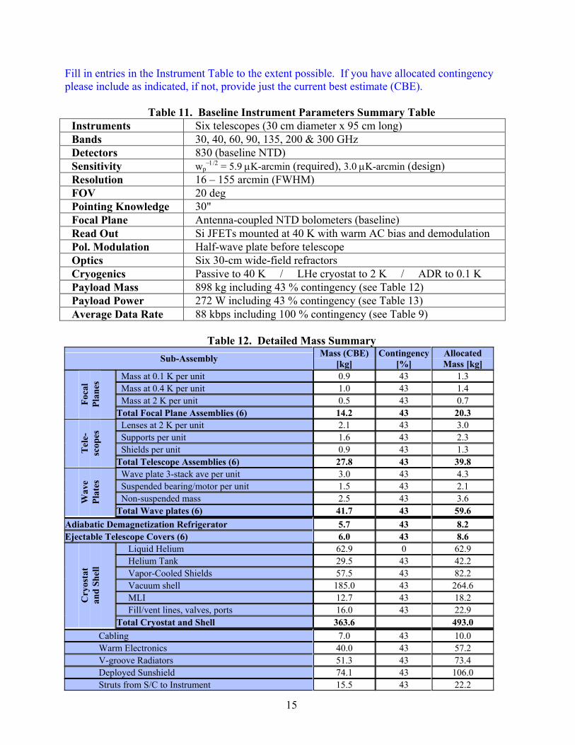
Fill in entries in the Instrument Table to the extent possible. If you have allocated contingency please include as indicated, if not, provide just the current best estimate (CBE).
Table 11. Baseline Instrument Parameters Summary Table Instruments Six telescopes (30 cm diameter x 95 cm long) Bands 30, 40, 60, 90, 135, 200 & 300 GHz Detectors 830 (baseline NTD) Sensitivity wp
−1/2 = 5.9 μK-arcmin (required), 3.0 μK-arcmin (design) Resolution 16 – 155 arcmin (FWHM) FOV 20 deg Pointing Knowledge 30" Focal Plane Antenna-coupled NTD bolometers (baseline) Read Out Si JFETs mounted at 40 K with warm AC bias and demodulation Pol. Modulation Half-wave plate before telescope Optics Six 30-cm wide-field refractors Cryogenics Passive to 40 K / LHe cryostat to 2 K / ADR to 0.1 K Payload Mass 898 kg including 43 % contingency (see Table 12) Payload Power 272 W including 43 % contingency (see Table 13) Average Data Rate 88 kbps including 100 % contingency (see Table 9)
Table 12. Detailed Mass Summary
Sub-Assembly Mass (CBE) [kg]
Contingency [%]
Allocated Mass [kg]
Mass at 0.1 K per unit 0.9 43 1.3 Mass at 0.4 K per unit 1.0 43 1.4 Mass at 2 K per unit 0.5 43 0.7 Fo
cal
Plan
es
Total Focal Plane Assemblies (6) 14.2 43 20.3 Lenses at 2 K per unit 2.1 43 3.0 Supports per unit 1.6 43 2.3 Shields per unit 0.9 43 1.3 T
ele-
scop
es
Total Telescope Assemblies (6) 27.8 43 39.8 Wave plate 3-stack ave per unit 3.0 43 4.3 Suspended bearing/motor per unit 1.5 43 2.1 Non-suspended mass 2.5 43 3.6 W
ave
Plat
es
Total Wave plates (6) 41.7 43 59.6 Adiabatic Demagnetization Refrigerator 5.7 43 8.2 Ejectable Telescope Covers (6) 6.0 43 8.6
Liquid Helium 62.9 0 62.9 Helium Tank 29.5 43 42.2 Vapor-Cooled Shields 57.5 43 82.2 Vacuum shell 185.0 43 264.6 MLI 12.7 43 18.2 Fill/vent lines, valves, ports 16.0 43 22.9
Cry
osta
t an
d Sh
ell
Total Cryostat and Shell 363.6 493.0 Cabling 7.0 43 10.0 Warm Electronics 40.0 43 57.2 V-groove Radiators 51.3 43 73.4 Deployed Sunshield 74.1 43 106.0 Struts from S/C to Instrument 15.5 43 22.2

16
Subtotal for Wet Payload 646.9 898.3 Attitude Control System 81.9 43 117.1 C&DH 24.1 43 34.5 Power 52.6 43 75.2 Propulsion (dry) 22.1 43 31.6 Structures and mechanisms 212.9 43 304.4 Launch adapter 14.3 43 20.4 Cabling 46.4 43 66.4 Telecom + X-band Antenna 18.7 43 26.7 Thermal 25.5 43 36.5 Propellant [ΔV = 215 m/s] 172.0 0 172.0
Subtotal for Wet Spacecraft 670.5 884.8 Total Launch Mass 1318 1783 Launch Vehicle Maximum Payload Mass to L2 (C3 = -0.6) Vehicle Pld Mass [kg] Margin [%] Margin [kg] Atlas V 401 3485 95 1702 Delta IV 4040 2773 56 990
Table 13. Power Summary Item Power (CBE) [W] Contingency [%] Allocated [W]
Bolometer Electronics 150 43 215 ADR Electronics 40 43 57
Subtotal Payload 190 43 272 Attitude Control 264 43 378 C&DH 69 43 99 Power 106 43 152 Propulsion 25 43 36 Telecom (transmit mode) 191 43 273 Thermal 31 43 44
Subtotal Spacecraft 686 43 981 Total Power 876 43 1253 GaAs Triple Junction Solar Panels Panel Area Power [W] Margin [%] Margin [W] 4.0 m2 Fixed at 45˚ Incidence 710 3.8 m2 Deployed at 45˚ Incidence 670 Total 1380 10 127 Optional details – If you have answers to the following detailed questions, please provide: For the science instrumentation, describe any concept, feasibility, or definition studies already performed (to respond you may provide copies of concept study reports, technology implementation plans, etc). Task Force for Cosmic Microwave Background Research (Weiss committee) defined the parameters for a space-borne CMB polarization mission. This report is available online, astro-ph 0604101. Engineering reports on the design of the sunshield and the study of the L2 orbit are available upon request. We are in the process of preparing a final report summarizing the results of

17
our mission study of the Einstein Inflation Probe to NASA, which will also be made available upon request. For instrument operations, provide a functional description of operational modes, and ground and on-orbit calibration schemes. A functional description of the single science mode, the scanning/precessing scan strategy, is described in Table 8 above. On-orbit the instrument will be absolutely calibrated to high accuracy from the annual modulation by the CMB dipole by the earth's velocity around the sun. The daily CMB dipole serves as a transfer standard, and also allows an accurate instantaneous measurement of the relative gain between polarized channel pairs. Main beam parameters will be measured on bright astrophysical point sources. Because the instrument is contained in a cryostat, we are planning to carry out a system-level calibration prior to integration with the spacecraft. Efficiency of polarization modulation will be measured on the ground. Cross-polarization and instrumental polarization will be calibrated using flight data and will be verified against measurements on the ground. Describe the level of complexity associated with analyzing the data to achieve the scientific objectives of the investigation.
Analysis of the EPIC data requires the statistical detection of CMB polarization anisotropies and their separation from foreground components. Both of these functions will be carried out by Planck, with higher angular resolution but lower sensitivity. Thus the complexity of the analysis is best assessed by comparison with Planck. Factors that increase complexity: -- EPIC's noise level is an order of magnitude lower than Planck's, which requires control of
systematic errors to an order of magnitude lower as well. -- EPIC has an order of magnitude more detectors, each of which must be treated separately. Factors that decrease complexity: -- EPIC beam sizes are an order of magnitude greater. The data rate per detector is ten times lower,
leading to an overall data rate comparable to Planck, but with 100 times fewer pixels in the maps. Given the very steep scaling of computing time with number of pixels and pixel size, this is a large simplification.
-- EPIC has only one type of detector, and covers a smaller frequency range. -- Systematic polarization errors are removed to negligible levels in hardware in EPIC, using a scan
strategy that gives much greater uniformity of effective beam sizes and shapes on the sky, and with much greater uniformity of polarization angle coverage. These place less stringent demands on the assessment and removal of these errors in software. Furthermore, systematic errors are more easily assessed than in Planck due to the highly redundant daily maps.
The factors decreasing complexity outweigh those increasing complexity. On balance,
Planck data analysis provides an upper bound to EPIC analysis. Especially given that in addition to Planck, several suborbital experiments with great sensitivity over smaller parts of the sky will provide a rigorous test of polarization analysis methods at noise levels approaching EPIC, we expect EPIC data analysis to be a straightforward extension of that for prior experiments.

18
Provide an instrument development schedule if available. Our development schedule for the instrument is 18 months for phase A, 12 months for phase B, and 48 months for phase C/D. The phase C/D duration may seem longer than typical, but we feel 48 months is appropriate due to the cryogenic nature of the instrumentation. Note the spacecraft phase C/D is assumed to be 37 months, and decoupled from the instrument phase C/D. Provide a schedule and plans for addressing any required technology developments, and the associated risks. The technology developments required for the baseline mission are modest. Specific items for development are antenna-coupled bolometers, the deployed sunshield, and the toroidal-beam antenna. Antenna-coupled bolometers have been demonstrated at 100 and 150 GHz in laboratory testing. In particular, the optical properties of the antennas have been measured to the specifications of EPIC, including polarized beam patterns, spectral passbands, and optical efficiency. The antenna designs need to be scaled in frequency to the other EPIC spectral bands. In terms of risk mitigation, we note that antennas are only necessary for the 30 and 40 GHz bands in the baseline. The bands above 90 GHz can use the feed-coupled PSBs developed for Planck. The Planck PSBs are suitable for 75 GHz, so some modest development would be needed to operate feed-coupled PSBs at 60 GHz. The deployed sunshield is a high-TRL hinged design. Our mission planning assumes the sunshield is fabricated by an industrial partner who provides a qualification model that is tested at JPL prior to the delivery of the flight unit. Likewise, the toroidal-beam antenna will be developed as qualification model for testing and characterization at JPL. As a fallback, the antenna can be replaced by a gimbaled, continuously rotating conventional antenna. We believe that both of these developments are modest in scope as the sunshield and antenna are well within state-of-the-art for similar flight-proven systems. The TES option is based on new detectors and read outs, and would only be considered if these technologies were mature at the time of the AO for a mission opportunity. TES detectors and read outs are currently being developed under R&A funding from NASA, and are being fielded in a variety of sub-orbital instruments (EBEX, SPIDER, South Pole Telescope, Atacama Cosmology Telescope, SCUBA 2) funded by NASA and NSF. TES bolometer arrays are emerging rapidly, with first-light planned in 2007 for SCUBA 2, SPT, and ACT. Successful demonstration in a balloon environment by EBEX and SPIDER will bring these technologies to TRL 6. Describe the complexity of the instrument flight software, including estimate of the number of lines of code.
The flight software complexity for this mission is low. Flight software supports a single continuous science mode: EPIC has one instrument, one observing mode used for the whole science mission, one moving part (the rotating half-wave plate), one scan strategy, modest requirements on pointing accuracy and knowledge, routine station keeping at L2, and modest downlink data rates. By comparison to observatory-class missions, these demands on flight software are simple. Compare the scientific reach of your mission with that of other planned space and ground-based missions.

19
EPIC provides approximately 10 times higher sensitivity than Planck, as shown in Table 5, and 300 times higher than WMAP, as shown in Fig. 1. The EPIC scan strategy is ideal for polarimetry, and a significant improvement over that of WMAP and Planck as shown in Fig. 7. Finally, unlike WMAP and Planck which were originally conceived to measure temperature anisotropies, EPIC is designed specifically to suppress systematic errors in polarization, and includes low-polarization optics and a polarization modulator placed in front of the telescope as shown in Fig. 5.
Mission Design
Please answer the following as completely as possible: • Provide a brief descriptive overview of the mission design (launch, orbit, pointing strategy) and
how it achieves the science requirements (e.g. if you need to cover the entire sky, how is it achieved?).
EPIC carries out scientific observations from an L2 halo orbit. We reach L2 approximately 170 days after launch by means of a transfer orbit using lunar assist. The delta-V budget of 215 km/s includes 72 +/- 45 km/s for injection errors, a conservative trajectory correction strategy, and 4 years of orbit correction at L2. We take 95 % probability on all maneuver errors add then include an additional 10 % overall margin. The sunshield is deployed and the aperture lids are ejected early in the mission in order to reduce the heat load on the cryostat en route to L2.
Once at L2, the instrument executes a single observing mode which consists of a spinning/precessing scan strategy. This strategy provides uniform and redundant coverage of the sky and efficiently rotates the telescope direction on all regions of the sky. Data are transmitted to earth once per day via a toroidal-beam antenna, which enables downlink during observations without the use of a counter-rotating antenna. The single-shot adiabatic demagnetization refrigerator is cycled at regular intervals of 48 hours. The half wave plates in front of each telescope are stepped every 24 hours to remove the systematic effects of main beam asymmetries.
Table 14. Summary of EPIC Delta-V Budget
Note: Units are m/s. Less conservative correction strategies, such as used on Genesis, would reduce the total budget by 40-80 m/s. Reducing the design lifetime at L2 to 2 years would save a further 62 m/s.

20
Fig. 6. Coverage of the sky for a single pixel in the focal plane for (top) three spin cycles in 3 minutes, and (middle) one precession cycle in 1 hour. Coverage in one precession cycle is a bit larger than 50 % of the sky. Note that wide range of crossing angles in the middle figure. At bottom, we show the uniformity in the crossing angle on the sky, <sin 2β>2 + <cos 2β>2, where β is the crossing angle on each pixel of sky, after a single day of observing. An ideal polarization experiment would obtain <sin 2β>2 + <cos 2β>2 = 0, very nearly achieved over the majority of this daily map.

21
Planck
WMAP
EPIC
<sin 2β>2 + <cos 2β>2
0 1
Fig. 7. The uniformity in the crossing angle on the sky, <sin 2β>2 + <cos 2β>2, where β is the crossing angle on each pixel of sky, after six months of observing for Planck, WMAP, and EPIC. An ideal polarization experiment would obtain <sin 2β>2 + <cos 2β>2 = 0. The EPIC scan strategy provides nearly perfect angular uniformity, and is significantly improved compared to Planck and WMAP. • Provide entries in the mission design table to the extent possible. Those entries in italics are
optional. For mass and power, provide contingency if it has been allocated, if not – provide just your current best estimate (CBE). To calculate margin, take the difference between the maximum possible value (e.g. launch vehicle capability) and the maximum expected value (CBE plus contingency).

22
Table 15. Mission Design Summary Orbit L2 Halo Mission Life 1 year at L2 (required), 2 years at L2 (design) Maximum Eclipse Period 0 Spacecraft dry bus mass and contingency 713 kg, includes 43 % contingency Spacecraft propellant mass and contingency
172 kg (ΔV budget, contingency, and margin shown in Table 14)
Launch vehicle Atlas V 401, Delta IV 4040, option for Delta 2925H-9.5 Star 48
Launch vehicle mass margin 1702 kg (95 %), 990 kg (56 %) Spacecraft bus power and contingency by subsystem
See Table 18
Mass weighted reuse percentage of payload and spacecraft subsystem components
We define reuse as commercial hardware at TRL = 9. Spacecraft components have 90 % reuse by mass, calculated excluding structure and cable mass. The payload has 5 % reuse by mass.
Mass weighted redundancy of payload and spacecraft subsystem components
Spacecraft components have 20 % redundancy by mass, calculated excluding structure and cable mass. The payload has 0 % redundancy by mass.
• Provide diagrams or drawings (if you have them) showing the observatory (payload and s/c)
with the components labeled and a descriptive caption. If you have a diagram of the observatory in the launch vehicle fairing indicating clearance, please provide it.
Fig. 8. Overview of the EPIC payload in deployed and stowed configurations. The instrument consists of a 450 liter liquid helium cryostat enclosing six 30-cm telescopes, each with an array of 100 mK bolometers. The cryostat is mounted on bipod supports with a 3-stage V-groove radiator to the spacecraft. Power is provided by body mounted and hinged solar panels at the bottom of the spacecraft. A deployed 3-stage sunshield keeps solar and re-radiated thermal power from reaching the cryostat vacuum shell. The sunshield stows to fit inside a 3-m launch fairing. Each telescope is sealed with a fly-away lid that deploys prior to observations. While we have sized the experiment to fit within the parameters of a Delta-II 2925H, we have baselined an Atlas V 401 launch based on best current information on future Delta-II availability and cost.
23
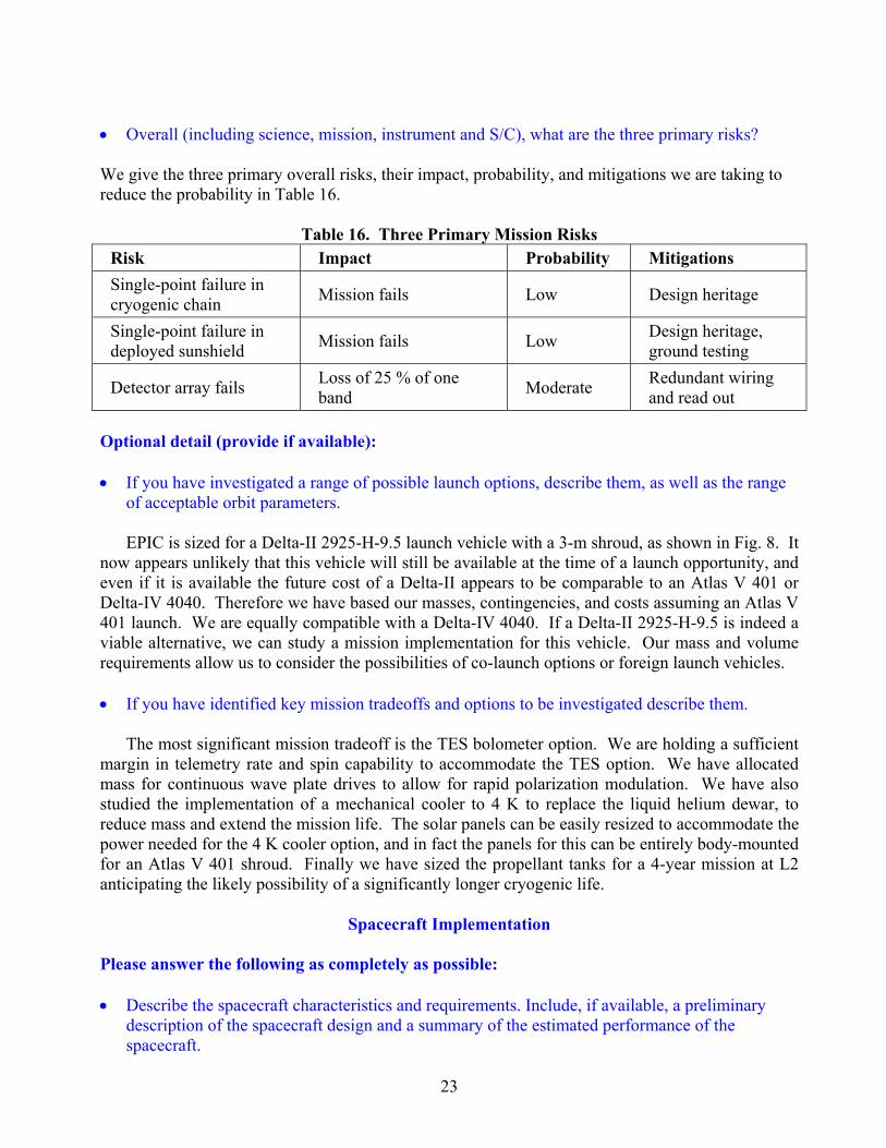
• Overall (including science, mission, instrument and S/C), what are the three primary risks? We give the three primary overall risks, their impact, probability, and mitigations we are taking to reduce the probability in Table 16.
Table 16. Three Primary Mission Risks Risk Impact Probability Mitigations Single-point failure in cryogenic chain Mission fails Low Design heritage
Single-point failure in deployed sunshield Mission fails Low Design heritage,
ground testing
Detector array fails Loss of 25 % of one band Moderate Redundant wiring
and read out Optional detail (provide if available): • If you have investigated a range of possible launch options, describe them, as well as the range
of acceptable orbit parameters.
EPIC is sized for a Delta-II 2925-H-9.5 launch vehicle with a 3-m shroud, as shown in Fig. 8. It now appears unlikely that this vehicle will still be available at the time of a launch opportunity, and even if it is available the future cost of a Delta-II appears to be comparable to an Atlas V 401 or Delta-IV 4040. Therefore we have based our masses, contingencies, and costs assuming an Atlas V 401 launch. We are equally compatible with a Delta-IV 4040. If a Delta-II 2925-H-9.5 is indeed a viable alternative, we can study a mission implementation for this vehicle. Our mass and volume requirements allow us to consider the possibilities of co-launch options or foreign launch vehicles. • If you have identified key mission tradeoffs and options to be investigated describe them.
The most significant mission tradeoff is the TES bolometer option. We are holding a sufficient margin in telemetry rate and spin capability to accommodate the TES option. We have allocated mass for continuous wave plate drives to allow for rapid polarization modulation. We have also studied the implementation of a mechanical cooler to 4 K to replace the liquid helium dewar, to reduce mass and extend the mission life. The solar panels can be easily resized to accommodate the power needed for the 4 K cooler option, and in fact the panels for this can be entirely body-mounted for an Atlas V 401 shroud. Finally we have sized the propellant tanks for a 4-year mission at L2 anticipating the likely possibility of a significantly longer cryogenic life.
Spacecraft Implementation
Please answer the following as completely as possible: • Describe the spacecraft characteristics and requirements. Include, if available, a preliminary
description of the spacecraft design and a summary of the estimated performance of the spacecraft.

24
Table 17. Spacecraft Requirements and Capabilities
RSDO Summary Capability Units Spectrum Astro SA-200HP EPIC Requirement
Payload Power (OAV) (EOL) W 650 272 (includes 43 % contingency)
Payload Mass Limit of Bus kg 666 898 (includes 43 % contingency)
Bus Dry Mass (w/o Payload) kg 354
Science Data Downlink Capability kbps 50,000 (X-band) 500 (baseline) 4,000 (TES option)
Science Data Storage Capability Gbit 100 16 (baseline) 215 (TES option)
Pointing Knowledge arcsec 0.5 30 Pointing Control arcsec 16 3600 Pointing stability (jitter) arcsec/s 0.1 20
Slewrate deg/min 120 360 (baseline) 1080 (TES option)
Mission Design Life yrs 4 2
Compatible LVs Taurus, Athena I, Athena II, Delta II, Titan II, Atlas
Atlas V 401, Delta IV 4040, Delta II
Types of Orbit Available LEO circular (nominal), many other orbits available
Earth-Sun L2
Com
patib
ility
Internal Volume Available for Payload 100 cm dia. x 75 cm tall Sufficient for warm electronics
Attitude Control System 3-axis zero momentum
bias/thruster based management
3-axis momentum compensated
Batteries type/Ah Two NiH2 50 Ah each Two at 24 Ah each
Arrays Type/ area
Triple junction GaInP/GaAs/Ge
10.32 m2
Triple junction GaAs 4.0 m2 body mounted
3.8 m2 deployed Nominal Voltage V 28 28 C&CH Bus Architecture VME-based 32-bit RISC 422 or 1553 Downlink Formats CCSDS: STDN/DSN CCSDS Downlink Band X-band and S-band X-band
Structure Octagonal, Al space frame construction with honeycomb
Al or composite
Propulsion Blowdown hydrazine system Hydrazine Propellant Capacity kg 67 172
Des
crip
tion
Mass Delta-V m/s 131 215 Heritage Missions New Millennium Deep Space 1 Nominal Schedule months 36 36
Contract Options Full Redundancy Replace S/C telecom with toroidal antenna
Deep Space Configuration Body mounted and deployed solar panels
Ground Segment Integration Support
Add momentum wheel in spin axis
Modify propulsion tanks
Prog
ram
mat
ic
Modify mechanical support

25
The requirements on the spacecraft are described in Table 17 above. We assume EPIC will operate with a custom-built commercial spacecraft bus. However, we note that the requirements are close to the capabilities of a modified ‘off-the-shelf’ commercial bus. As an example, we show below the specifications of the Spectrum Astro-200HP spacecraft, the capabilities of which (from the RSDO catalog), are close to our specifications. For specificity, we compare our requirements to a modified SA-200HP, but at this stage in the project we have not selected an industrial partner and many options for a spacecraft are available. • Provide an overall assessment of the technical maturity of the subsystems and critical
components. In particular, identify any required new technologies or developments or open implementation issues.
The spacecraft itself requires no new technology. A custom-designed X-band antenna producing a toroidal beam is baselined. This item would be provided equipment to the spacecraft vendor. However, the downlink requirements could be satisfied by a gimbaled conventional antenna that continuously counter spins at 1 rpm. Furthermore, the toroidal antenna is over specified for the low data rate of the baseline and could be descoped to a simpler design in this scenario. EPIC requires a bus-mounted solar panel plus 4 hinged deployed panels on the sun-facing side of the bus. The deployable sunshield would be a provided payload element and is not part of the spacecraft.
• What are the three greatest risks with the S/C? We give the three primary risks for the spacecraft, their impact, probability, and mitigations we are taking to reduce the probability in Table 18.
Table 18. Three Primary Spacecraft Risks Risk Impact Probability Mitigations
Sun avoidance Possible loss of mission through cryogen boil off Low Spitzer, WMAP sun-
avoidance heritage
Navigation at L2 Eclipsing by the earth Low WMAP, Planck heritage
Dynamic stability with flexible sunshield Pointing jitter Low
Modest 30" requirement on pointing knowledge, post reconstruction
Optional detail (provide if you have selected a specific S/C implementation): • If you have required new S/C technologies, developments or open issues and you have
identified plans to address them, please describe (to answer you may provide technology implementation plan reports or concept study reports).
The design of the toroidal-beam antenna is shown below. The antenna would be developed by JPL and provided to the spacecraft vendor. The antenna is based on space-qualified components and has low technical risk. We plan to qualify this unit at component level. A fallback is to replace this antenna with a continuously counter-rotating gimbaled antenna.

26
Fig. 9. Design of the toroidal-beam antenna used for data downlink. The antenna produces a low-gain toroidal beam pattern with an opening half angle of 45 degrees. The opening angle of the beam pattern is large enough to account for all variations to the sun-spacecraft-earth angle over the life of the mission. This antenna eliminates the associated risks of a continuously counter-rotating gimbaled antenna (reliability, microphonics). The antenna would be developed and qualified at JPL and provided to the spacecraft vendor. • Describe subsystem characteristics and requirements to the extent possible. Such characteristics
include: mass, volume, and power; pointing knowledge and accuracy; data rates; and a summary of margins.
EPIC requirements on the spacecraft bus are summarized in the Spacecraft Characteristics Table 19. An estimate of subsystem masses and power requirements based on a team-X study (which assumes a custom-built spacecraft bus) as follows:
HORN RADIATOR
RADOME
Z
WR-112 WAVEGUIDES (RCP AND LCP)
MOUNTING FLANGE
CONICAL RADIATED
BEAM 45O
SEPTUM POLARIZER
SUBREFLECTOR
MAIN REFLECTOR
380 mm

27
Table 19. Spacecraft Sub-System Characteristics S/C Subsystem Mass
[kg, CBE] Mass Ctgcy.
[%] Power
[W, CBE] Power
Ctgcy. [%] Attitude Control System 81.9 43 264 43 C&DH 24.1 43 69 43 Power 52.6 43 106 43 Propulsion (dry) 22.1 43 25 43 Structures and mechanisms 212.9 43 Launch adapter 14.3 43 Cabling 46.4 43 Telecom + X-band Antenna 18.7 43 191 43 Thermal 25.5 43 31 43 Propellant [ΔV = 215 m/s] 172.0 43
• Describe the flight heritage of the spacecraft and its subsystems. Indicate items that are to be
developed, as well as any existing instrumentation or design/flight heritage. Discuss the steps needed for space qualification.
All required spacecraft hardware is existing (previously flown) technology, with the exception of the JPL-provided antenna. • Address to the extent possible the accommodation of the science instruments by the spacecraft.
In particular, identify any challenging or non-standard requirements (i.e. Jitter/momentum considerations, thermal environment/temperature limits etc).
Basic requirements to the spacecraft are as follows: Payload Mass: The total mass of the payload, including the deployable sunshield, support struts, X-band antenna, and LHe is 898 kg, which includes 43 % contingency on all masses except LHe. Payload Power: The total payload power required is 272 W, including 43 % contingency. Instrument Output Data Rate: 87 kbps (baseline). 1260 kbps (TES option). Instrument Pointing/Scanning: Continuous 1 rpm spin; continuous 1 rph coning/precession (baseline). 3 rpm spin; 3 rph precession (TES option). These requirements do not present challenges to the spacecraft design. • Define the technology readiness level of critical S/C items along with a rationale for the
assigned rating.
The spacecraft itself requires no new technologies -- all technologies are at a TRL of 9, having been previously flown. The X-band antenna is provided equipment. Its TRL is estimated between 4 and 5 but is composed entirely of TRL = 9 space-proven components. • Provide a preliminary schedule for the spacecraft development.
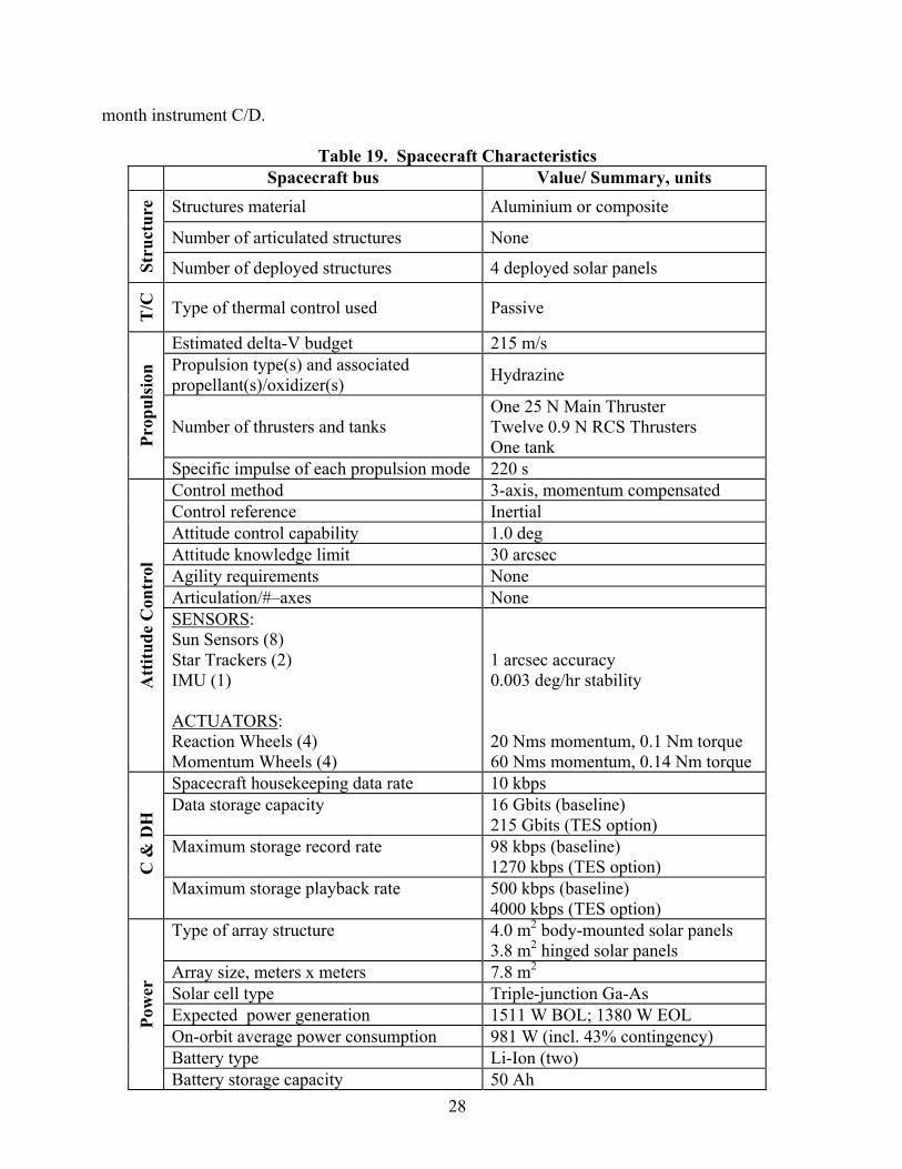
A 37-month spacecraft delivery schedule is assumed, consistent with a standard commercial bus. The schedule impact of utilizing body-mounted solar panels and a customer-provided X-band antenna is not significant. We assume that the spacecraft phase C/D is decoupled from the 48-
28
month instrument C/D.
Table 19. Spacecraft Characteristics Spacecraft bus Value/ Summary, units
Structures material Aluminium or composite
Number of articulated structures None
Stru
ctur
e
Number of deployed structures 4 deployed solar panels
T/C
Type of thermal control used Passive
Estimated delta-V budget 215 m/s Propulsion type(s) and associated propellant(s)/oxidizer(s) Hydrazine
Number of thrusters and tanks One 25 N Main Thruster Twelve 0.9 N RCS Thrusters One tank Pr
opul
sion
Specific impulse of each propulsion mode 220 s Control method 3-axis, momentum compensated Control reference Inertial Attitude control capability 1.0 deg Attitude knowledge limit 30 arcsec Agility requirements None Articulation/#–axes None
Att
itude
Con
trol
SENSORS: Sun Sensors (8) Star Trackers (2) IMU (1) ACTUATORS: Reaction Wheels (4) Momentum Wheels (4)
1 arcsec accuracy 0.003 deg/hr stability 20 Nms momentum, 0.1 Nm torque 60 Nms momentum, 0.14 Nm torque
Spacecraft housekeeping data rate 10 kbps Data storage capacity 16 Gbits (baseline)
215 Gbits (TES option) Maximum storage record rate 98 kbps (baseline)
1270 kbps (TES option) C &
DH
Maximum storage playback rate 500 kbps (baseline) 4000 kbps (TES option)
Type of array structure 4.0 m2 body-mounted solar panels 3.8 m2 hinged solar panels
Array size, meters x meters 7.8 m2 Solar cell type Triple-junction Ga-As Expected power generation 1511 W BOL; 1380 W EOL On-orbit average power consumption 981 W (incl. 43% contingency) Battery type Li-Ion (two)
Pow
er
Battery storage capacity 50 Ah
29
NOTE: the values supplied in this table are the EPIC requirements -- not the specifications for any particular implementation. The vendor for the spacecraft bus for this mission has not yet been selected.
Mission Operations
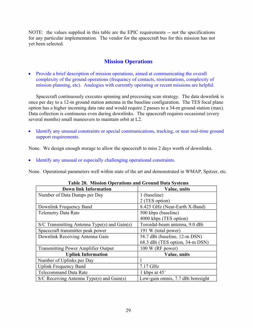
• Provide a brief description of mission operations, aimed at communicating the overall complexity of the ground operations (frequency of contacts, reorientations, complexity of mission planning, etc). Analogies with currently operating or recent missions are helpful.
Spacecraft continuously executes spinning and precessing scan strategy. The data downlink is once per day to a 12-m ground station antenna in the baseline configuration. The TES focal plane option has a higher incoming data rate and would require 2 passes to a 34-m ground station (max). Data collection is continuous even during downlinks. The spacecraft requires occasional (every several months) small maneuvers to maintain orbit at L2. • Identify any unusual constraints or special communications, tracking, or near real-time ground
support requirements. None. We design enough storage to allow the spacecraft to miss 2 days worth of downlinks. • Identify any unusual or especially challenging operational constraints. None. Operational parameters well within state of the art and demonstrated in WMAP, Spitzer, etc.
Table 20. Mission Operations and Ground Data Systems
Down link Information Value, units Number of Data Dumps per Day 1 (baseline)
2 (TES option) Downlink Frequency Band 8.425 GHz (Near-Earth X-Band) Telemetry Data Rate 500 kbps (baseline)
4000 kbps (TES option) S/C Transmitting Antenna Type(s) and Gain(s) Toroidal-beam antenna, 9.0 dBi Spacecraft transmitter peak power 191 W (total power) Downlink Receiving Antenna Gain 58.7 dBi (baseline, 12-m DSN)
68.3 dBi (TES option, 34-m DSN) Transmitting Power Amplifier Output 100 W (RF power)
Uplink Information Value, units Number of Uplinks per Day 1 Uplink Frequency Band 7.17 GHz Telecommand Data Rate 1 kbps at 45˚ S/C Receiving Antenna Type(s) and Gain(s) Low-gain omnis, 7.7 dBi boresight

30
TOTAL MISSION COST FUNDING PROFILE TEMPLATE
(FY costs1 in Real Year Dollars, Totals in Real Year and 2007 Dollars)
Item FY09 FY10 FY11 FY12 FY13 FY14 FY15 FY16 Total (RY)
Total (FY07)
Phase A A-B B-C/D C/D C/D C/D C/D-E E
Concept Study 0.1 2.7 1.3 - - - - - 4.1 3.7Science 0.0 0.1 0.6 2.4 3.5 3.6 6.0 8.4 24.7 19.6Instrument 0.1 1.2 9.4 37.2 55.3 57.1 31.1 - 191.4 157.9Spacecraft 0.1 1.0 8.1 31.9 47.4 48.9 26.6 - 164.0 135.3Ground Data System Dev 0.0 0.1 1.2 4.6 6.8 7.0 3.8 - 23.4 19.3MSI&T 2 0.0 0.1 0.4 0.3 0.4 3.9 4.1 - 9.2 7.4Launch services - - - 28.4 52.6 54.2 29.5 - 164.7 135.0MO&DA3 - - - - - - 5.8 12.0 17.8 13.7Education/Outreach 0.0 0.0 0.0 0.1 0.2 0.2 0.7 1.3 2.6 2.0Reserves 0.0 0.9 7.0 27.8 41.4 42.6 24.9 3.5 148.3 122.1Project Management 0.0 0.1 0.6 2.4 3.5 3.7 2.3 0.7 13.1 10.7Project System Engineering 0.0 0.1 0.9 3.4 5.1 5.2 2.8 - 17.5 14.4Safety Mission Assurance 0.0 0.1 1.0 3.8 5.6 5.8 3.2 0.1 19.5 16.1
Total Cost 0.3 6.3 30.4 142.3 221.7 232.0 146.9 26.1 800.2 657.4Total Contributions - - - - - - - - - -
Total Mission Cost 657.4
1 Costs should include all costs including any fee 2 MSI&T - Mission System Integration and Test and preparation for operations 3 MO&DA - Mission Operations and Data Analysis
Note on cost estimate: Costs were generated by JPL’s Advanced Concurrent Engineering Design Team (Team X), which includes experts in science, mission design, instruments, programmatics, ground system, and every spacecraft subsystem. Team members synthesize their own expertise and discipline-specific models to generate complete mission studies including cost details. JPL has used Team X to generate well over 600 project studies. The Parametric Mission Cost Model (PMCM) is widely used for estimating project costs. It is comprised of a series of cost estimating relationships (CERs) that represent the cost of each project WBS element. The CERs were derived by multiple regression techniques from about 150 (Team X) studies. CERs take into account the key engineering technical drivers that affect mission cost. PMCM has been validated against the costs of actual missions flown by JPL. Prior to the team-x session, the instrument costs for the deployable sunshade, antenna, cryostat, telescopes, focal plane detector arrays, and warm and cold readout electronics were calculated based on a grassroots basis by the team members involved in their design. These costs were scaled from actual costs on similar hardware delivered for Planck and Herschel where applicable. The grassroots cost for the instrument was $145M (FY07), so we instead used the larger team-X model-based instrument cost of $158M (FY07) in the above table. NAFCOM In order to validate the costs for the EPIC Mission, the costs were cross checked using NAFCOM v.2006, build date 4/18/2006. The NAFCOM costs for this mission were estimated to be

31
$706M (FY07) after applying a 30% reserve, in good agreement with the above cost table. The inputs to NAFCOM were based on the mass and power summaries shown in Tables 12 and 13 assuming an unmanned, earth-orbiting, scientific mission category. Analogy to Spitzer. In order to further cross-check our cost estimate, we carried out a comparison to the actual costs of a similar cryogenic mission. The best example available was Spitzer, an infrared great observatory with a suite of 3 science instruments launched in 2003 with a cost of $1075M (FY07) for phases A-E without extended operations. We applied the following reductions to the Spitzer actual costs: 1) change phase E from 30 to 18 months; 2) scale the instrument development for a 48 month phase C/D from a 66 month phase C/D; 3) reduce the instrument requirements (3 instruments with a near-infrared diffraction-limited Be telescope to a single 100 mK instrument with mm-wave optics); 4) scale the spacecraft based on the less demanding pointing, control and data rate requirements for EPIC; 5) reduce the flight software for a single operating mode; 6) reduce the science management costs from that of a great observatory. Then we made the following additions: 1) add deployable sunshade cost; 2) add custom antenna; and 3) add higher launch vehicle cost. The estimate based on these adjustments agrees within 10 % of the above cost estimate, although we must emphasize that the adjustments are significant due to the dissimilarity of the two missions. Disclaimer: The total estimated mission cost provided here are for budgetary and planning purposes only and does not constitute a commitment on the part of Caltech/JPL.