resistors & circuits resistance. many types of ... two of these bands indicate two numbers and...
TRANSCRIPT
RESISTORS & CIRCUITS MODULE 2.PDF 1 E. COATES 2015
Resistors & Circuits
Module 2.0
Resistors
Resistor Construction
Resistors are components used to resist the flow of electric current and have a stated value of RESISTANCE. Many types of
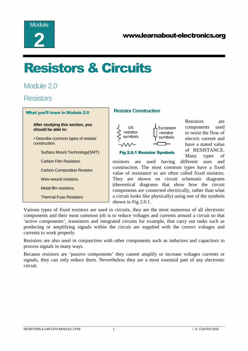
resistors are used having different uses and construction. The most common types have a fixed value of resistance so are often called fixed resistors. They are shown on circuit schematic diagrams (theoretical diagrams that show how the circuit components are connected electrically, rather than what a circuit looks like physically) using one of the symbols shown in Fig 2.0.1.
Various types of fixed resistors are used in circuits, they are the most numerous of all electronic components and their most common job is to reduce voltages and currents around a circuit so that ‘active components’, transistors and integrated circuits for example, that carry out tasks such as producing or amplifying signals within the circuit are supplied with the correct voltages and currents to work properly.
Resistors are also used in conjunction with other components such as inductors and capacitors to process signals in many ways.
Because resistors are ‘passive components’ they cannot amplify or increase voltages currents or signals, they can only reduce them. Nevertheless they are a most essential part of any electronic circuit.
www.learnabout-electronics.org
Module
2
What you’ll learn in Module 2.0
After studying this section, you should be able to:
• Describe common types of resistor construction.
Surface Mount Technology(SMT).
Carbon Film Resistors.
Carbon Composition Resistor.
Wire-wound resistors.
Metal film resistors.
Thermal Fuse Resistors
Fig 2.0.1 Resistor Symbols
www.learnabout-electronics.org Resistors & Circuits Module 2
RESISTORS AND CIRCUITS MODULE 02 PDF 2 E. COATES 2015
Carbon Film Resistors
1Watt resistor
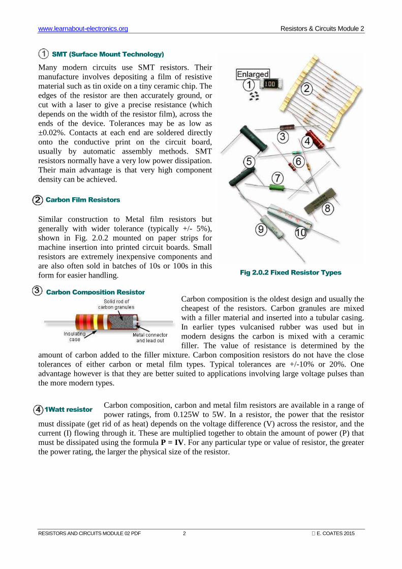
Many modern circuits use SMT resistors. Their manufacture involves depositing a film of resistive material such as tin oxide on a tiny ceramic chip. The edges of the resistor are then accurately ground, or cut with a laser to give a precise resistance (which depends on the width of the resistor film), across the ends of the device. Tolerances may be as low as ±0.02%. Contacts at each end are soldered directly onto the conductive print on the circuit board, usually by automatic assembly methods. SMT resistors normally have a very low power dissipation. Their main advantage is that very high component density can be achieved.
Similar construction to Metal film resistors but generally with wider tolerance (typically +/- 5%), shown in Fig. 2.0.2 mounted on paper strips for machine insertion into printed circuit boards. Small resistors are extremely inexpensive components and are also often sold in batches of 10s or 100s in this form for easier handling.
Carbon composition is the oldest design and usually the cheapest of the resistors. Carbon granules are mixed with a filler material and inserted into a tubular casing. In earlier types vulcanised rubber was used but in modern designs the carbon is mixed with a ceramic filler. The value of resistance is determined by the
amount of carbon added to the filler mixture. Carbon composition resistors do not have the close tolerances of either carbon or metal film types. Typical tolerances are +/-10% or 20%. One advantage however is that they are better suited to applications involving large voltage pulses than the more modern types.
Carbon composition, carbon and metal film resistors are available in a range of power ratings, from 0.125W to 5W. In a resistor, the power that the resistor
must dissipate (get rid of as heat) depends on the voltage difference (V) across the resistor, and the current (I) flowing through it. These are multiplied together to obtain the amount of power (P) that must be dissipated using the formula P = IV. For any particular type or value of resistor, the greater the power rating, the larger the physical size of the resistor.
Fig 2.0.2 Fixed Resistor Types
Carbon Composition Resistor
SMT (Surface Mount Technology)
www.learnabout-electronics.org Resistors & Circuits Module 2
RESISTORS AND CIRCUITS MODULE 02 PDF 3 E. COATES 2015
5 Watt Wirewound Resistor
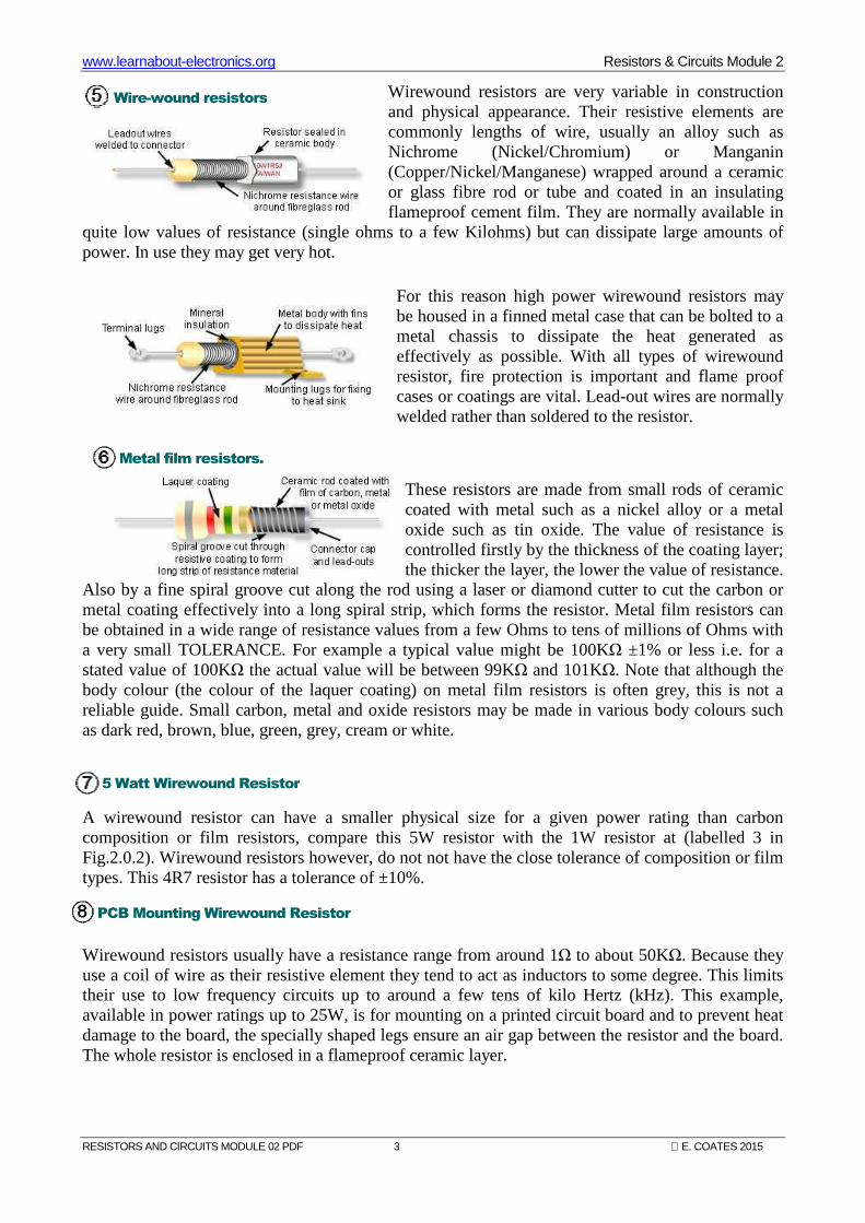
Wirewound resistors are very variable in construction and physical appearance. Their resistive elements are commonly lengths of wire, usually an alloy such as Nichrome (Nickel/Chromium) or Manganin (Copper/Nickel/Manganese) wrapped around a ceramic or glass fibre rod or tube and coated in an insulating flameproof cement film. They are normally available in
quite low values of resistance (single ohms to a few Kilohms) but can dissipate large amounts of power. In use they may get very hot.
For this reason high power wirewound resistors may be housed in a finned metal case that can be bolted to a metal chassis to dissipate the heat generated as effectively as possible. With all types of wirewound resistor, fire protection is important and flame proof cases or coatings are vital. Lead-out wires are normally welded rather than soldered to the resistor.
These resistors are made from small rods of ceramic coated with metal such as a nickel alloy or a metal oxide such as tin oxide. The value of resistance is controlled firstly by the thickness of the coating layer; the thicker the layer, the lower the value of resistance.
Also by a fine spiral groove cut along the rod using a laser or diamond cutter to cut the carbon or metal coating effectively into a long spiral strip, which forms the resistor. Metal film resistors can be obtained in a wide range of resistance values from a few Ohms to tens of millions of Ohms with a very small TOLERANCE. For example a typical value might be 100KΩ ±1% or less i.e. for a stated value of 100KΩ the actual value will be between 99KΩ and 101KΩ. Note that although the body colour (the colour of the laquer coating) on metal film resistors is often grey, this is not a reliable guide. Small carbon, metal and oxide resistors may be made in various body colours such as dark red, brown, blue, green, grey, cream or white.
A wirewound resistor can have a smaller physical size for a given power rating than carbon composition or film resistors, compare this 5W resistor with the 1W resistor at (labelled 3 in Fig.2.0.2). Wirewound resistors however, do not not have the close tolerance of composition or film types. This 4R7 resistor has a tolerance of ±10%.
Wirewound resistors usually have a resistance range from around 1Ω to about 50KΩ. Because they use a coil of wire as their resistive element they tend to act as inductors to some degree. This limits their use to low frequency circuits up to around a few tens of kilo Hertz (kHz). This example, available in power ratings up to 25W, is for mounting on a printed circuit board and to prevent heat damage to the board, the specially shaped legs ensure an air gap between the resistor and the board. The whole resistor is enclosed in a flameproof ceramic layer.
Wire-wound resistors
Metal film resistors.
PCB Mounting Wirewound Resistor
www.learnabout-electronics.org Resistors & Circuits Module 2
RESISTORS AND CIRCUITS MODULE 02 PDF 4 E. COATES 2015
Metal film resistors are also available in high power types with power ratings less than wirewound types (typically less than 5W) but having closer tolerances.
In this fusible resistor, the current flowing through the resistor first flows through a spring-loaded connection that is positioned close to the body of the resistor. The heat generated by the wirewound resistor under normal conditions would not be sufficient to melt the blob of solder holding a spring wire in place. If too much current flows through the resistor it overheats, the solder melts and the wire springs up, opening the connection and stopping the current. This then requires a service technician to find the cause of the over-current before re-soldering the spring connection to restore normal operation. It is important to use the correct type of solder (usually stated in the service manual for the equipment) when re-soldering, since this will affect the temperature at which the spring opens.
High Power Metal Film
Fusible Wirewound Resistor
www.learnabout-electronics.org Resistors & Circuits Module 2
RESISTORS AND CIRCUITS MODULE 02 PDF 5 E. COATES 2015
Module 2.1 Resistor Colour Codes
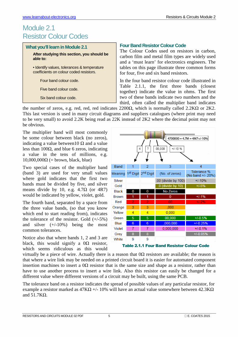
Four Band Resistor Colour Code The Colour Codes used on resistors in carbon, carbon film and metal film types are widely used and a ‘must learn’ for electronics engineers. The tables on this page illustrate three common forms for four, five and six band resistors.
In the four band resistor colour code illustrated in Table 2.1.1, the first three bands (closest together) indicate the value in ohms. The first two of these bands indicate two numbers and the third, often called the multiplier band indicates
the number of zeros, e.g. red, red, red indicates 2200Ω, which is normally called 2.2KΩ or 2K2. This last version is used in many circuit diagrams and suppliers catalogues (where print may need to be very small) to avoid 2.2K being read as 22K instead of 2K2 where the decimal point may not be obvious.
The multiplier band will most commonly be some colour between black (no zeros), indicating a value between10 Ω and a value less than 100Ω, and blue 6 zeros, indicating a value in the tens of millions, e.g. 10,000,000Ω (= brown, black, blue)
Two special cases of the multiplier band (band 3) are used for very small values where gold indicates that the first two bands must be divided by five, and silver means divide by 10, e.g. 4.7Ω (or 4R7) would be indicated by yellow, violet, gold.
The fourth band, separated by a space from the three value bands, (so that you know which end to start reading from), indicates the tolerance of the resistor. Gold (+/-5%) and silver (+/-10%) being the most common tolerances.
Notice also that where bands 1, 2 and 3 are black, this would signify a 0Ω resistor, which seems ridiculous as this would virtually be a piece of wire. Actually there is a reason that 0Ω resistors are available; the reason is that where a wire link may be needed on a printed circuit board it is easier for automated component insertion machines to insert a 0Ω resistor that is the same size and shape as a resistor, rather than have to use another process to insert a wire link. Also this resistor can easily be changed for a different value where different versions of a circuit may be built, using the same PCB.
The tolerance band on a resistor indicates the spread of possible values of any particular resistor, for example a resistor marked as 47KΩ +/- 10% will have an actual value somewhere between 42.3KΩ and 51.7KΩ.
What you’ll learn in Module 2.1 After studying this section, you should be able to:
• Identify values, tolerances & temperature coefficients on colour coded resistors.
Four band colour code.
Five band colour code.
Six band colour code.
Table 2.1.1 Four Band Resistor Colour Code
www.learnabout-electronics.org Resistors & Circuits Module 2
RESISTORS AND CIRCUITS MODULE 02 PDF 6 E. COATES 2015
Five Band Resistor Colour Code
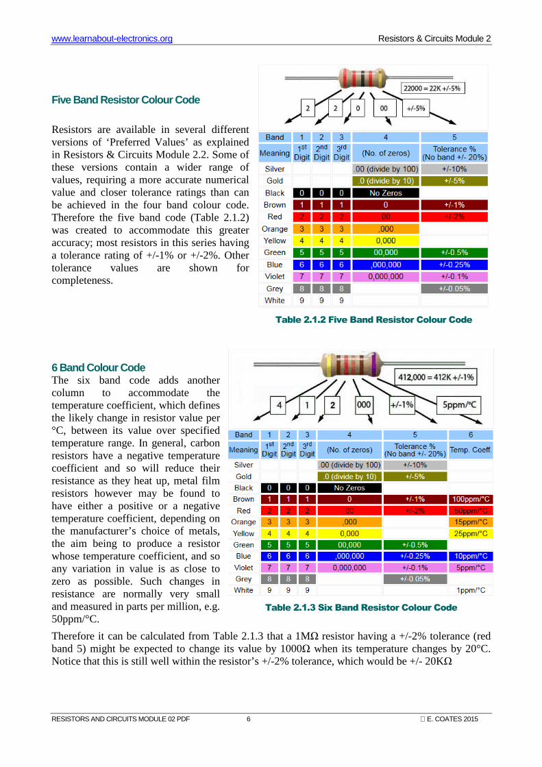
Resistors are available in several different versions of ‘Preferred Values’ as explained in Resistors & Circuits Module 2.2. Some of these versions contain a wider range of values, requiring a more accurate numerical value and closer tolerance ratings than can be achieved in the four band colour code. Therefore the five band code (Table 2.1.2) was created to accommodate this greater accuracy; most resistors in this series having a tolerance rating of +/-1% or +/-2%. Other tolerance values are shown for completeness.
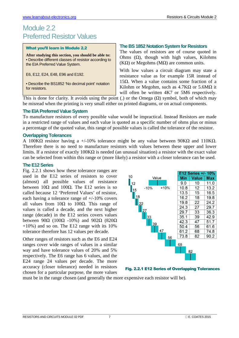
6 Band Colour Code The six band code adds another column to accommodate the temperature coefficient, which defines the likely change in resistor value per °C, between its value over specified temperature range. In general, carbon resistors have a negative temperature coefficient and so will reduce their resistance as they heat up, metal film resistors however may be found to have either a positive or a negative temperature coefficient, depending on the manufacturer’s choice of metals, the aim being to produce a resistor whose temperature coefficient, and so any variation in value is as close to zero as possible. Such changes in resistance are normally very small and measured in parts per million, e.g. 50ppm/°C.
Therefore it can be calculated from Table 2.1.3 that a 1MΩ resistor having a +/-2% tolerance (red band 5) might be expected to change its value by 1000Ω when its temperature changes by 20°C. Notice that this is still well within the resistor’s +/-2% tolerance, which would be +/- 20KΩ
Table 2.1.2 Five Band Resistor Colour Code
Table 2.1.3 Six Band Resistor Colour Code
www.learnabout-electronics.org Resistors & Circuits Module 2
RESISTORS AND CIRCUITS MODULE 02 PDF 7 E. COATES 2015
Module 2.2 Preferred Resistor Values
The BS 1852 Notation System for Resistors The values of resistors are of course quoted in Ohms (Ω), though with high values, Kilohms (KΩ) or Megohms (MΩ) are common units.
With low values a circuit diagram may state a resistance value as for example 15R instead of 15Ω. When a value contains some fraction of a Kilohm or Megohm, such as 4.7KΩ or 5.6MΩ it will often be written 4K7 or 5M6 respectively.
This is done for clarity. It avoids using the point (.) or the Omega (Ω) symbol, both of which may be misread when the printing is very small either on printed diagrams, or on actual components.
The EIA Preferred Value System To manufacture resistors of every possible value would be impractical. Instead Resistors are made in a restricted range of values and each value is quoted as a specific number of ohms plus or minus a percentage of the quoted value, this range of possible values is called the tolerance of the resistor.
Overlapping Tolerances A 100KΩ resistor having a +/-10% tolerance might be any value between 90KΩ and 110KΩ. Therefore there is no need to manufacture resistors with values between these upper and lower limits. If a resistor of exactly 100KΩ is needed (an unusual situation) a resistor with the exact value can be selected from within this range or (more likely) a resistor with a closer tolerance can be used.
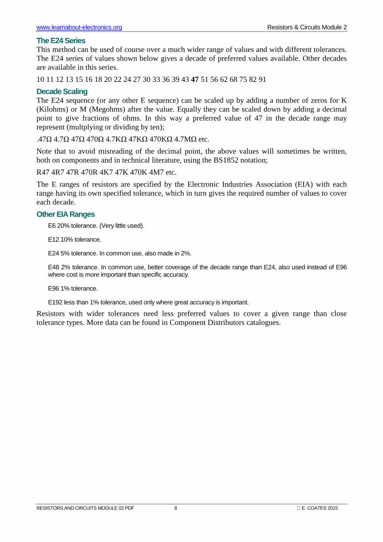
The E12 Series Fig. 2.2.1 shows how these tolerance ranges are used in the E12 series of resistors to cover (almost) all possible values of resistance between 10Ω and 100Ω. The E12 series is so called because 12 ‘Preferred Values’ of resistor, each having a tolerance range of +/-10% covers all values from 10Ω to 100Ω. This range of values is called a decade, and the next higher range (decade) in the E12 series covers values between 90Ω (100Ω -10%) and 902Ω (820Ω +10%) and so on. The E12 range with its 10% tolerance therefore has 12 values per decade.
Other ranges of resistors such as the E6 and E24 ranges cover wide ranges of values in a similar way and have tolerance values of 20% and 5% respectively. The E6 range has 6 values, and the E24 range 24 values per decade. The more accuracy (closer tolerance) needed in resistors chosen for a particular purpose, the more values must be in the range chosen (and generally the more expensive each resistor will be).
What you’ll learn in Module 2.2
After studying this section, you should be able to: • Describe different classes of resistor according to the EIA Preferred Value System. E6, E12, E24, E48, E96 and E192.
• Describe the BS1852 ‘No decimal point’ notation for resistors.
Fig. 2.2.1 E12 Series of Overlapping Tolerances
www.learnabout-electronics.org Resistors & Circuits Module 2
RESISTORS AND CIRCUITS MODULE 02 PDF 8 E. COATES 2015
The E24 Series This method can be used of course over a much wider range of values and with different tolerances. The E24 series of values shown below gives a decade of preferred values available. Other decades are available in this series.
10 11 12 13 15 16 18 20 22 24 27 30 33 36 39 43 47 51 56 62 68 75 82 91
Decade Scaling The E24 sequence (or any other E sequence) can be scaled up by adding a number of zeros for K (Kilohms) or M (Megohms) after the value. Equally they can be scaled down by adding a decimal point to give fractions of ohms. In this way a preferred value of 47 in the decade range may represent (multplying or dividing by ten);
.47Ω 4.7Ω 47Ω 470Ω 4.7KΩ 47KΩ 470KΩ 4.7MΩ etc.
Note that to avoid misreading of the decimal point, the above values will sometimes be written, both on components and in technical literature, using the BS1852 notation;
R47 4R7 47R 470R 4K7 47K 470K 4M7 etc.
The E ranges of resistors are specified by the Electronic Industries Association (EIA) with each range having its own specified tolerance, which in turn gives the required number of values to cover each decade.
Other EIA Ranges E6 20% tolerance. (Very little used).
E12 10% tolerance.
E24 5% tolerance. In common use, also made in 2%.
E48 2% tolerance. In common use, better coverage of the decade range than E24, also used instead of E96 where cost is more important than specific accuracy.
E96 1% tolerance.
E192 less than 1% tolerance, used only where great accuracy is important.
Resistors with wider tolerances need less preferred values to cover a given range than close tolerance types. More data can be found in Component Distributors catalogues.
www.learnabout-electronics.org Resistors & Circuits Module 2
RESISTORS AND CIRCUITS MODULE 02 PDF 9 E. COATES 2015
Module 2.3 Surface Mount Resistors
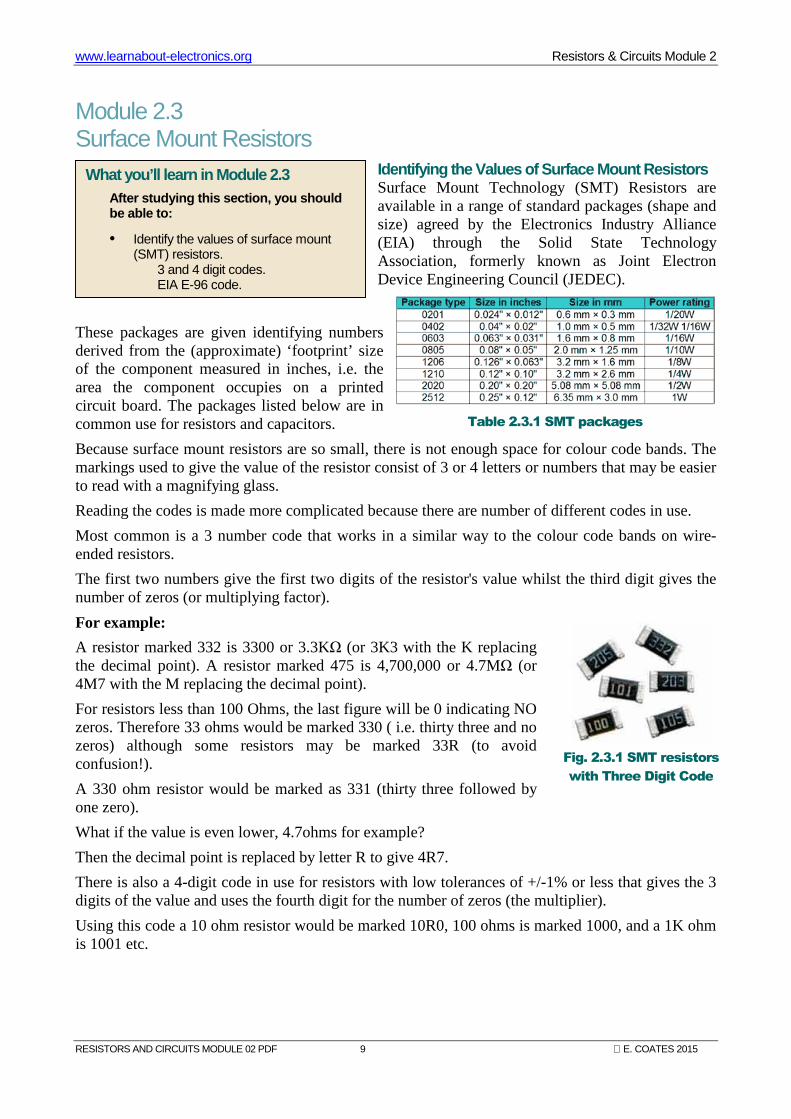
Identifying the Values of Surface Mount Resistors Surface Mount Technology (SMT) Resistors are available in a range of standard packages (shape and size) agreed by the Electronics Industry Alliance (EIA) through the Solid State Technology Association, formerly known as Joint Electron Device Engineering Council (JEDEC).
These packages are given identifying numbers derived from the (approximate) ‘footprint’ size of the component measured in inches, i.e. the area the component occupies on a printed circuit board. The packages listed below are in common use for resistors and capacitors.
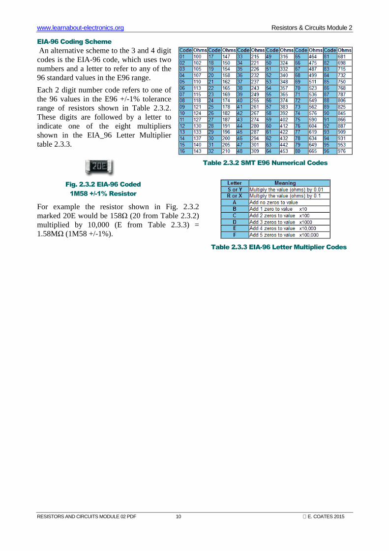
Because surface mount resistors are so small, there is not enough space for colour code bands. The markings used to give the value of the resistor consist of 3 or 4 letters or numbers that may be easier to read with a magnifying glass.
Reading the codes is made more complicated because there are number of different codes in use.
Most common is a 3 number code that works in a similar way to the colour code bands on wire-ended resistors.
The first two numbers give the first two digits of the resistor's value whilst the third digit gives the number of zeros (or multiplying factor).
For example:
A resistor marked 332 is 3300 or 3.3KΩ (or 3K3 with the K replacing the decimal point). A resistor marked 475 is 4,700,000 or 4.7MΩ (or 4M7 with the M replacing the decimal point).
For resistors less than 100 Ohms, the last figure will be 0 indicating NO zeros. Therefore 33 ohms would be marked 330 ( i.e. thirty three and no zeros) although some resistors may be marked 33R (to avoid confusion!).
A 330 ohm resistor would be marked as 331 (thirty three followed by one zero).
What if the value is even lower, 4.7ohms for example?
Then the decimal point is replaced by letter R to give 4R7.
There is also a 4-digit code in use for resistors with low tolerances of +/-1% or less that gives the 3 digits of the value and uses the fourth digit for the number of zeros (the multiplier).
Using this code a 10 ohm resistor would be marked 10R0, 100 ohms is marked 1000, and a 1K ohm is 1001 etc.
What you’ll learn in Module 2.3 After studying this section, you should be able to:
• Identify the values of surface mount (SMT) resistors.
3 and 4 digit codes. EIA E-96 code.
Table 2.3.1 SMT packages
Fig. 2.3.1 SMT resistors
with Three Digit Code
www.learnabout-electronics.org Resistors & Circuits Module 2
RESISTORS AND CIRCUITS MODULE 02 PDF 10 E. COATES 2015
EIA-96 Coding Scheme
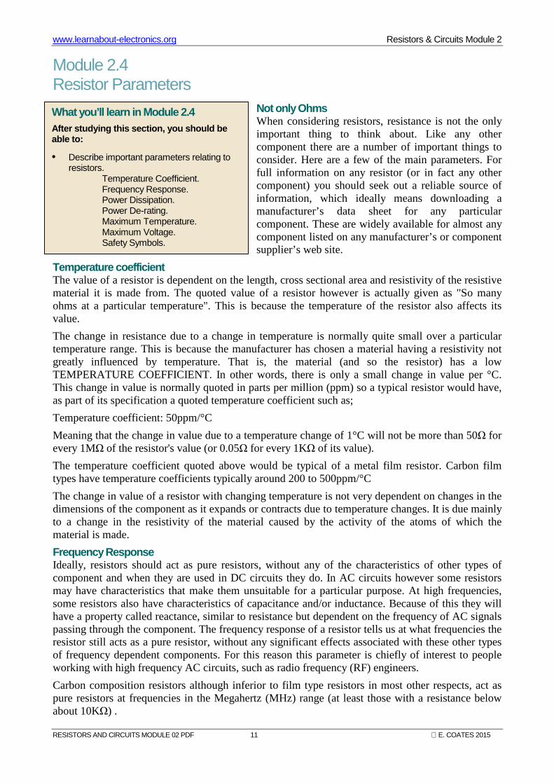
An alternative scheme to the 3 and 4 digit codes is the EIA-96 code, which uses two numbers and a letter to refer to any of the 96 standard values in the E96 range.
Each 2 digit number code refers to one of the 96 values in the E96 +/-1% tolerance range of resistors shown in Table 2.3.2. These digits are followed by a letter to indicate one of the eight multipliers shown in the EIA_96 Letter Multiplier table 2.3.3.
For example the resistor shown in Fig. 2.3.2 marked 20E would be 158Ω (20 from Table 2.3.2) multiplied by 10,000 (E from Table 2.3.3) = 1.58MΩ (1M58 +/-1%).
Table 2.3.2 SMT E96 Numerical Codes
Table 2.3.3 EIA-96 Letter Multiplier Codes
Fig. 2.3.2 EIA-96 Coded
1M58 +/-1% Resistor
www.learnabout-electronics.org Resistors & Circuits Module 2
RESISTORS AND CIRCUITS MODULE 02 PDF 11 E. COATES 2015
Module 2.4 Resistor Parameters
Not only Ohms When considering resistors, resistance is not the only important thing to think about. Like any other component there are a number of important things to consider. Here are a few of the main parameters. For full information on any resistor (or in fact any other component) you should seek out a reliable source of information, which ideally means downloading a manufacturer’s data sheet for any particular component. These are widely available for almost any component listed on any manufacturer’s or component supplier’s web site.
Temperature coefficient The value of a resistor is dependent on the length, cross sectional area and resistivity of the resistive material it is made from. The quoted value of a resistor however is actually given as "So many ohms at a particular temperature". This is because the temperature of the resistor also affects its value.
The change in resistance due to a change in temperature is normally quite small over a particular temperature range. This is because the manufacturer has chosen a material having a resistivity not greatly influenced by temperature. That is, the material (and so the resistor) has a low TEMPERATURE COEFFICIENT. In other words, there is only a small change in value per °C. This change in value is normally quoted in parts per million (ppm) so a typical resistor would have, as part of its specification a quoted temperature coefficient such as;
Temperature coefficient: 50ppm/°C
Meaning that the change in value due to a temperature change of 1°C will not be more than 50Ω for every 1MΩ of the resistor's value (or 0.05Ω for every 1KΩ of its value).
The temperature coefficient quoted above would be typical of a metal film resistor. Carbon film types have temperature coefficients typically around 200 to 500ppm/°C
The change in value of a resistor with changing temperature is not very dependent on changes in the dimensions of the component as it expands or contracts due to temperature changes. It is due mainly to a change in the resistivity of the material caused by the activity of the atoms of which the material is made.
Frequency Response Ideally, resistors should act as pure resistors, without any of the characteristics of other types of component and when they are used in DC circuits they do. In AC circuits however some resistors may have characteristics that make them unsuitable for a particular purpose. At high frequencies, some resistors also have characteristics of capacitance and/or inductance. Because of this they will have a property called reactance, similar to resistance but dependent on the frequency of AC signals passing through the component. The frequency response of a resistor tells us at what frequencies the resistor still acts as a pure resistor, without any significant effects associated with these other types of frequency dependent components. For this reason this parameter is chiefly of interest to people working with high frequency AC circuits, such as radio frequency (RF) engineers.
Carbon composition resistors although inferior to film type resistors in most other respects, act as pure resistors at frequencies in the Megahertz (MHz) range (at least those with a resistance below about 10KΩ) .
What you’ll learn in Module 2.4 After studying this section, you should be able to:
• Describe important parameters relating to resistors.
Temperature Coefficient. Frequency Response. Power Dissipation. Power De-rating. Maximum Temperature. Maximum Voltage. Safety Symbols.
www.learnabout-electronics.org Resistors & Circuits Module 2
RESISTORS AND CIRCUITS MODULE 02 PDF 12 E. COATES 2015
Film type resistors having a spiral construction do tend to exhibit the properties of inductors (which are basically spirally wound coils of wire) but this is not usually a problem until used at frequencies in the MHz range. Film type resistors that do not have a spiral track, such as surface mount resistors remain purely resistive up to hundreds of MHz.
The resistors with the worst frequency response are not surprisingly wirewound types, as their construction is really a coil of wire - just like an inductor. Therefore the inductance and reactance effects must be considered when using wirewound resistors in any circuit operating at frequencies above a few hundred Hertz (Hz). Wirewound resistors are used for high power applications and are available in resistances up to a few KΩ. At higher resistances high power metal film resistors may be used, although they do not have as high a power rating as some wirewound types, they do have a much better frequency response.
Power Dissipation This is a measure of the amount of power that a resistor can dissipate without causing it to overheat. Resistors are manufactured in standard power ratings and mostly these are in fractions of 1Watt with some larger carbon and metal resistors available in 1Watt to about 5Watts. Wirewound resistors are normally available in power ratings of up to about 25W, and special wirewound types are made by component manufacturers in much higher power ratings, often to the specifications of the customer (the equipment maker).
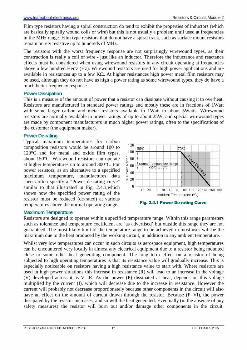
Power De-rating Typical maximum temperatures for carbon composition resistors would be around 100 to 120°C and for metal and oxide film types, about 150°C. Wirewound resistors can operate at higher temperatures up to around 300°C. For power resistors, as an alternative to a specified maximum temperature, manufactures data sheets often specify a "Power de-rating curve" similar to that illustrated in Fig. 2.4.1,which shows how the specified power rating of the resistor must be reduced (de-rated) at various temperatures above the normal operating range.
Maximum Temperature Resistors are designed to operate within a specified temperature range. Within this range parameters such as tolerance and temperature coefficient are ‘as advertised’ but outside this range they are not guaranteed. The most likely limit of the temperature range to be achieved in most uses will be the maximum due to the heat produced by the working circuit, in addition to any ambient temperature.
Whilst very low temperatures can occur in such circuits as aerospace equipment, high temperatures can be encountered very locally in almost any electrical equipment due to a resistor being mounted close to some other heat generating component. The long term effect on a resistor of being subjected to high operating temperatures is that its resistance value will gradually increase. This is especially noticeable on resistors having a high resistance value to start with. Where resistors are used in high power situations this increase in resistance (R) will lead to an increase in the voltage (V) developed across it as V=IR. As the power (P) dissipated as heat, depends on this voltage multiplied by the current (I), which will decrease due to the increase in resistance. However the current will probably not decrease proportionately because other components in the circuit will also have an effect on the amount of current drawn through the resistor. Because (P=VI), the power dissipated by the resistor increases, and so will the heat generated. Eventually (in the absence of any safety measures) the resistor will burn out and/or damage other components in the circuit.
Fig. 2.4.1 Power De-rating Curve
www.learnabout-electronics.org Resistors & Circuits Module 2
RESISTORS AND CIRCUITS MODULE 02 PDF 13 E. COATES 2015
Maximum Voltage
The voltage developed across a resistor as current flows through it places an electrical stress on the materials from which the resistor is made. If this voltage exceeds the permitted maximum there is a likelihood of a sudden breakdown of the resistor and a voltage flash over. The maximum voltage varies greatly between different types of resistor from just a few volts for some surface mount types to several thousand volts for some specialist high voltage resistors.
All the above parameters plus others such as the amount of random electrical noise generated, may need to be taken into account when selecting a resistor for a particular application. A reliable source of information such as a supplier’s catalogue or manufacturer’s data sheet should be consulted when choosing resistors.
When servicing equipment it is advisable to use replacement components supplied by the original manufacturer as far as is possible. In addition certain critical resistors in any piece of equipment may be labelled as a safety component with a small symbol similar to those shown in Fig 2.4.2. In these instances, ONLY the manufacturer's direct replacement is suitable. The markings shown are not universally adopted however, so when servicing any electronics equipment, close attention must be paid to manufacturer’s service manuals for the particular equipment being worked on.
Fig. 2.4.2 Safety
Component
Symbols.
www.learnabout-electronics.org Resistors & Circuits Module 2
RESISTORS AND CIRCUITS MODULE 02 PDF 14 E. COATES 2015
Module 2.5 Potentiometers & Variable Resistors
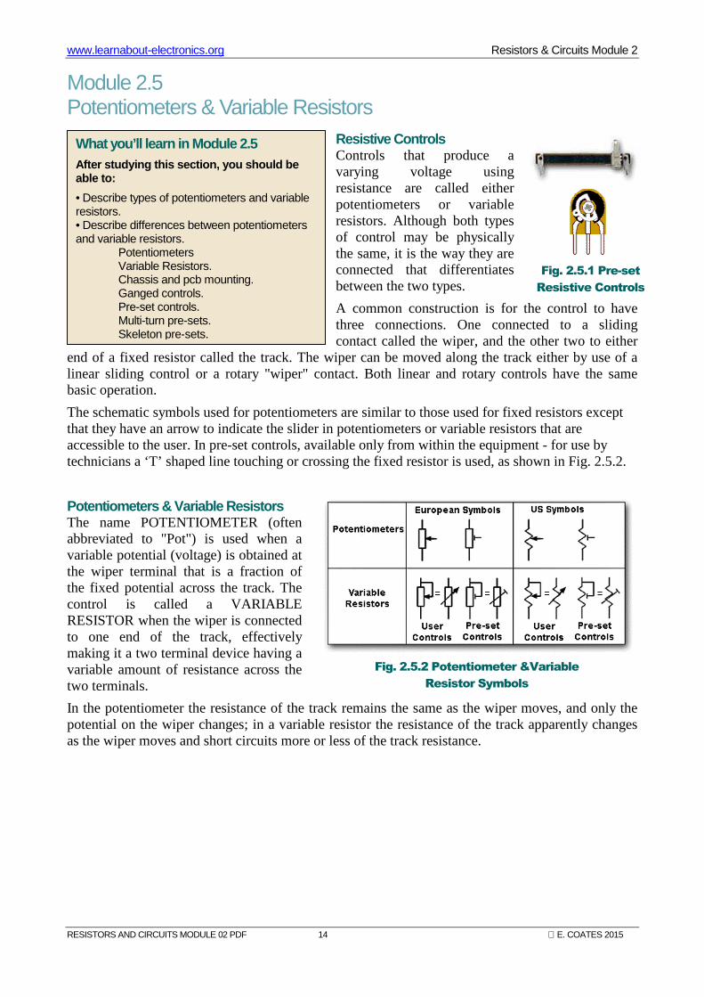
Resistive Controls Controls that produce a varying voltage using resistance are called either potentiometers or variable resistors. Although both types of control may be physically the same, it is the way they are connected that differentiates between the two types.
A common construction is for the control to have three connections. One connected to a sliding contact called the wiper, and the other two to either
end of a fixed resistor called the track. The wiper can be moved along the track either by use of a linear sliding control or a rotary "wiper" contact. Both linear and rotary controls have the same basic operation.
The schematic symbols used for potentiometers are similar to those used for fixed resistors except that they have an arrow to indicate the slider in potentiometers or variable resistors that are accessible to the user. In pre-set controls, available only from within the equipment - for use by technicians a ‘T’ shaped line touching or crossing the fixed resistor is used, as shown in Fig. 2.5.2.
Potentiometers & Variable Resistors The name POTENTIOMETER (often abbreviated to "Pot") is used when a variable potential (voltage) is obtained at the wiper terminal that is a fraction of the fixed potential across the track. The control is called a VARIABLE RESISTOR when the wiper is connected to one end of the track, effectively making it a two terminal device having a variable amount of resistance across the two terminals.
In the potentiometer the resistance of the track remains the same as the wiper moves, and only the potential on the wiper changes; in a variable resistor the resistance of the track apparently changes as the wiper moves and short circuits more or less of the track resistance.
What you’ll learn in Module 2.5 After studying this section, you should be able to:
• Describe types of potentiometers and variable resistors. • Describe differences between potentiometers and variable resistors.
Potentiometers Variable Resistors. Chassis and pcb mounting. Ganged controls. Pre-set controls. Multi-turn pre-sets. Skeleton pre-sets.
Fig. 2.5.1 Pre-set
Resistive Controls
Fig. 2.5.2 Potentiometer &Variable
Resistor Symbols
www.learnabout-electronics.org Resistors & Circuits Module 2
RESISTORS AND CIRCUITS MODULE 02 PDF 15 E. COATES 2015
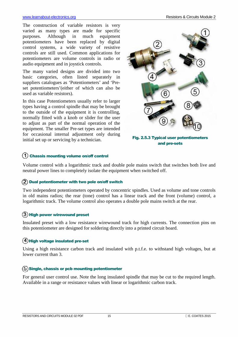
The construction of variable resistors is very varied as many types are made for specific purposes. Although in much equipment potentiometers have been replaced by digital control systems, a wide variety of resistive controls are still used. Common applications for potentiometers are volume controls in radio or audio equipment and in joystick controls.
The many varied designs are divided into two basic categories, often listed separately in suppliers catalogues as ‘Potentiometers’ and ‘Pre-set potentiometers’(either of which can also be used as variable resistors).
In this case Potentiometers usually refer to larger types having a control spindle that may be brought to the outside of the equipment it is controlling, normally fitted with a knob or slider for the user to adjust as part of the normal operation of the equipment. The smaller Pre-set types are intended for occasional internal adjustment only during initial set up or servicing by a technician.
Volume control with a logarithmic track and double pole mains switch that switches both live and neutral power lines to completely isolate the equipment when switched off.
Two independent potentiometers operated by concentric spindles. Used as volume and tone controls in old mains radios; the rear (tone) control has a linear track and the front (volume) control, a logarithmic track. The volume control also operates a double pole mains switch at the rear.
Insulated preset with a low resistance wirewound track for high currents. The connection pins on this potentiometer are designed for soldering directly into a printed circuit board.
Using a high resistance carbon track and insulated with p.t.f.e. to withstand high voltages, but at lower current than 3.
For general user control use. Note the long insulated spindle that may be cut to the required length. Available in a range or resistance values with linear or logarithmic carbon track.
Chassis mounting volume on/off control
Dual potentiometer with two pole on/off switch
High power wirewound preset
High voltage insulated pre-set
Single, chassis or pcb mounting potentiometer
Fig. 2.5.3 Typical user potentiometers
and pre-sets
www.learnabout-electronics.org Resistors & Circuits Module 2
RESISTORS AND CIRCUITS MODULE 02 PDF 16 E. COATES 2015
Two potentiometers sharing a single spindle are referred to as being ‘ganged’ (What one does, the other does.) Intended for applications such as stereo audio equipment so both channels may be adjusted simultaneously.
Two views of a precision slider preset, the wiper is made to slide slowly along the track by means of a screw thread turned by a small plastic gear wheel at the end. Provides a simple way of producing an accurately adjustable voltage.
Insulated miniature pre-set poentiometer for use with voltages up to 200V, pcb mounting, usually supplied with a small plug in shaft to fit the hexagonal centre hole for easier adjustment. Typical resitance values range from 100Ω to 1MΩ.
Skeleton presets refer to controls without an enclosing case. A basic track and wiper that can be adjusted using a small insulated adjusting tool, NOT a screwdriver! Intended for general setting up purposes and only occasional use.
A larger version of 9. Both of these controls are designed for PCB mounting. Upright and flat mounting versions are available. Modern types are usually fully enclosed but this example shows construction and operation more clearly. Small presets may have either carbon or ‘cermet’ (a mixture of ceramic and metal) tracks.
Dual ganged potentiometer
Multi-turn pre-set
Enclosed miniature preset potentiometer
Sub-miniature skeleton preset
Miniature skeleton preset
www.learnabout-electronics.org Resistors & Circuits Module 2
RESISTORS AND CIRCUITS MODULE 02 PDF 17 E. COATES 2015
Module 2.6 Logarithmic & Linear Controls
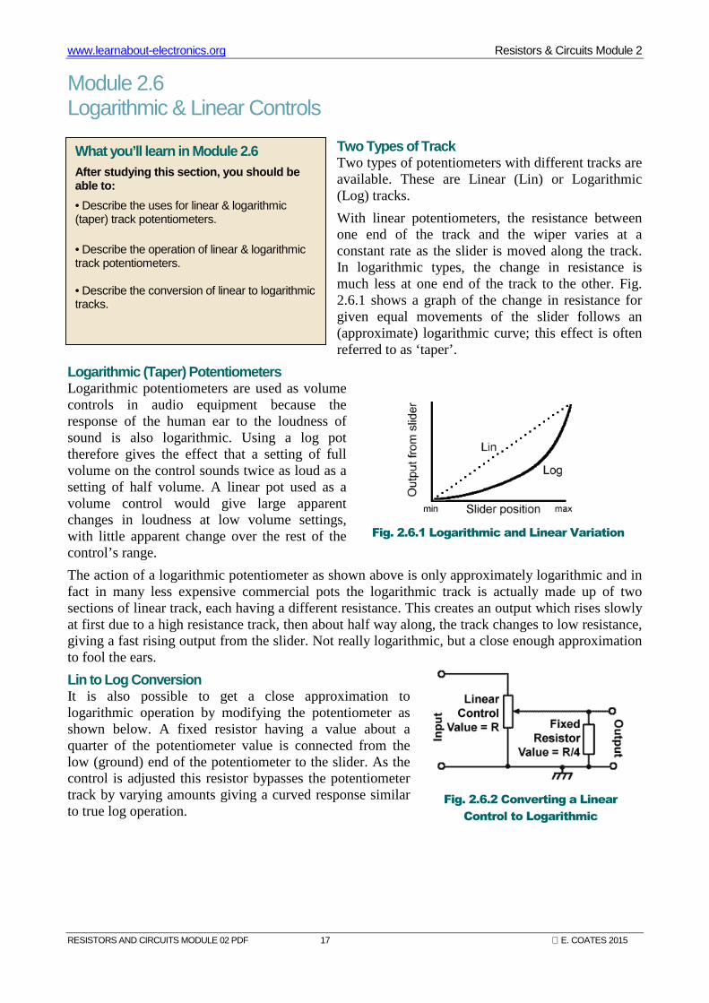
Two Types of Track Two types of potentiometers with different tracks are available. These are Linear (Lin) or Logarithmic (Log) tracks.
With linear potentiometers, the resistance between one end of the track and the wiper varies at a constant rate as the slider is moved along the track. In logarithmic types, the change in resistance is much less at one end of the track to the other. Fig. 2.6.1 shows a graph of the change in resistance for given equal movements of the slider follows an (approximate) logarithmic curve; this effect is often referred to as ‘taper’.
Logarithmic (Taper) Potentiometers Logarithmic potentiometers are used as volume controls in audio equipment because the response of the human ear to the loudness of sound is also logarithmic. Using a log pot therefore gives the effect that a setting of full volume on the control sounds twice as loud as a setting of half volume. A linear pot used as a volume control would give large apparent changes in loudness at low volume settings, with little apparent change over the rest of the control’s range.
The action of a logarithmic potentiometer as shown above is only approximately logarithmic and in fact in many less expensive commercial pots the logarithmic track is actually made up of two sections of linear track, each having a different resistance. This creates an output which rises slowly at first due to a high resistance track, then about half way along, the track changes to low resistance, giving a fast rising output from the slider. Not really logarithmic, but a close enough approximation to fool the ears.
Lin to Log Conversion It is also possible to get a close approximation to logarithmic operation by modifying the potentiometer as shown below. A fixed resistor having a value about a quarter of the potentiometer value is connected from the low (ground) end of the potentiometer to the slider. As the control is adjusted this resistor bypasses the potentiometer track by varying amounts giving a curved response similar to true log operation.
What you’ll learn in Module 2.6 After studying this section, you should be able to:
• Describe the uses for linear & logarithmic (taper) track potentiometers. • Describe the operation of linear & logarithmic track potentiometers. • Describe the conversion of linear to logarithmic tracks.
Fig. 2.6.1 Logarithmic and Linear Variation
Fig. 2.6.2 Converting a Linear
Control to Logarithmic