resilient network interconnect using distributed link
TRANSCRIPT
Resilient Network Interconnectusing Distributed Link Aggregation
Version 3b
(As presented in York. Only change since version 3 is addition of slide 4.)
Stephen HaddockExtreme Networks
September 16, 2010
1
Premise and Basic Questions• Adapting Link Aggregation to be a Resilient Network Interconnect
proposes that, at least for the purposes of Link Aggregation, we can make two or more ports on two or more bridges appear to be a single Bridge Port on a single Bridge when viewed from the NNI.
• Questions that immediately arise:1. How far does the “single bridge” illusion go?
• Only for Link Aggregation, or also for other protocols?• Only for the aggregated Bridge Port, or for the entire Bridge?• Just when viewed from the NNI, or also from the Network?
2. What happens when the illusion breaks down?• What is the failure mode behavior?
3. Does anything about the mechanism for creating the illusion need to be standardized?
• Even if we assume all the bridges involved are from a single vendor, is there anything in the externally observable behavior that needs to be standardized?
2
Two Basic Alternatives
1. Distributed Bridge ModelMake the multiple distinct bridges (the Nodes of a Distributed LAG
solution) appear to be a single bridge in all aspects, for all protocols, at all ports.
2. Distributed Port ModelMake the multiple distinct bridges (Nodes) appear to be a single
bridge only from the point of view the Link Aggregation partner.
To give away the punch line right at the start, I’m going to suggest that both alternatives should be allowed by a Resilient Network Interconnect standard based on Distributed Link Aggregation.
3
Exposing Assumptions• One goal of this presentation is to bring out assumptions inherent in a
particular D-LAG solution that may not be explicitly stated. • Examples of “This solution works (as long as … obviously)”
– … there is a direct link between the D-LAG nodes …– … there is a direct link that is never part of My Network’s active topology …– … there is a direct link that is always part of My Network’s active topology …– … Spanning Tree is not running in My Network …– … Spanning Tree is not running on the D-LAG ...– … everything that connects to either node connects to both …– … everything that connects to either node connects to both with a D-LAG …– … any given node only supports one D-LAG group …– … My Network does not have overlapping D-LAG groups …– … it doesn’t matter if addresses have to be relearned when an NNI link fails …– … link selection is based on VID …– … link selection is always reverse path congruent …– … data frames can be encapsulated and tunneled between the D-LAG nodes …
4
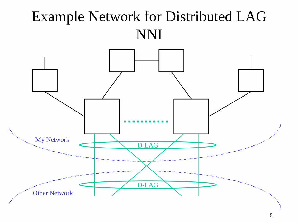
Example Network for Distributed LAG NNI
5
D-LAGMy Network
Other NetworkD-LAG
Distributed LAG Communications Channel
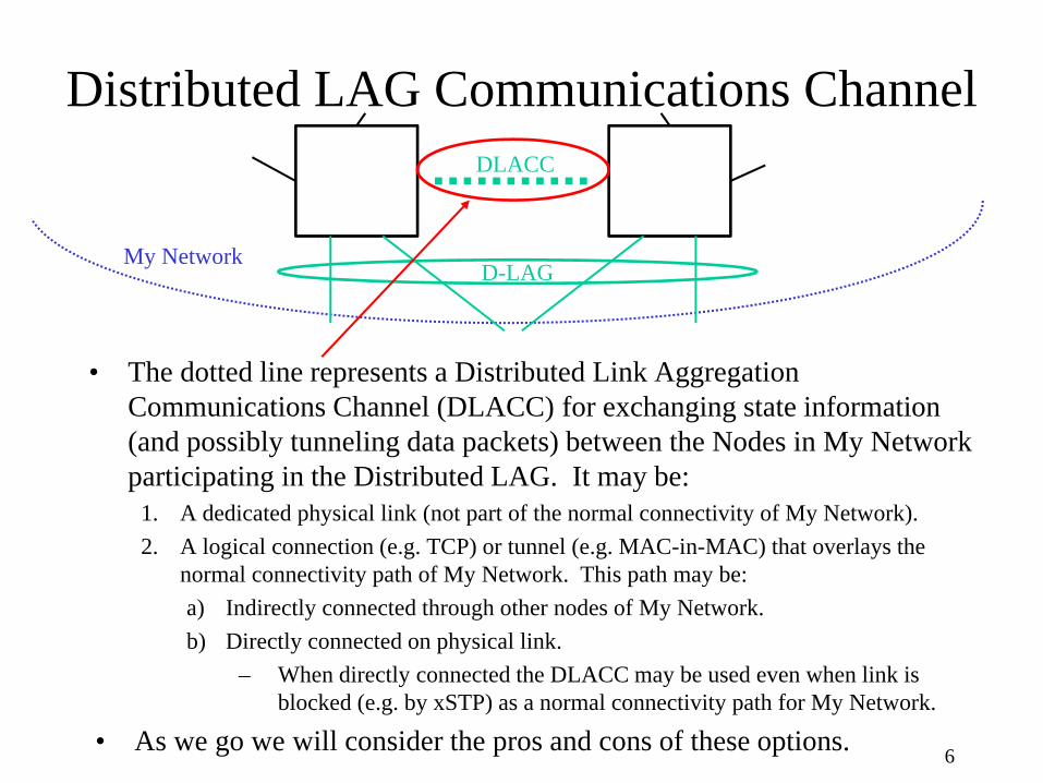
• The dotted line represents a Distributed Link Aggregation Communications Channel (DLACC) for exchanging state information (and possibly tunneling data packets) between the Nodes in My Network participating in the Distributed LAG. It may be:
1. A dedicated physical link (not part of the normal connectivity of My Network).2. A logical connection (e.g. TCP) or tunnel (e.g. MAC-in-MAC) that overlays the
normal connectivity path of My Network. This path may be:a) Indirectly connected through other nodes of My Network.b) Directly connected on physical link.
– When directly connected the DLACC may be used even when link is blocked (e.g. by xSTP) as a normal connectivity path for My Network.
• As we go we will consider the pros and cons of these options. 6
D-LAGMy Network
DLACC

‘Baggy Pants’ Representation
7
Higher Layer Entities
Relay
MAC
Higher Layer Entities
Relay
MAC
Link Aggregation
MAC MAC
Link Aggregation
MAC MAC
D-LAGMy Network
DLACC
DLACC
D-LAG
Distributed Bridge Model
8

Distributed Bridge
• A Distributed Bridge consists of two or more devices that together appear to be a single Bridge.– If the illusion of a single bridge is perfect, then by definition the
Distributed Bridge works anywhere a single bridge would work.• Theoretically if all the pieces of the Distributed Bridge come from a single
vendor, then nothing needs to be standardized.• Issue is that we may need to standardize behavior in situations where the
illusion isn’t perfect (failure modes for example), or when it is desirable to distinguish between a true single bridge and a distributed bridge.
– Note this is not the same, or even similar to, the Port Extender of p802.1Qbh.
• Assumption is that any device can continue to operate as a bridge should the other(s) fail.
• No objective to have all traffic relayed at a single “Controlling Bridge”.
9
Distributed Bridge Issues
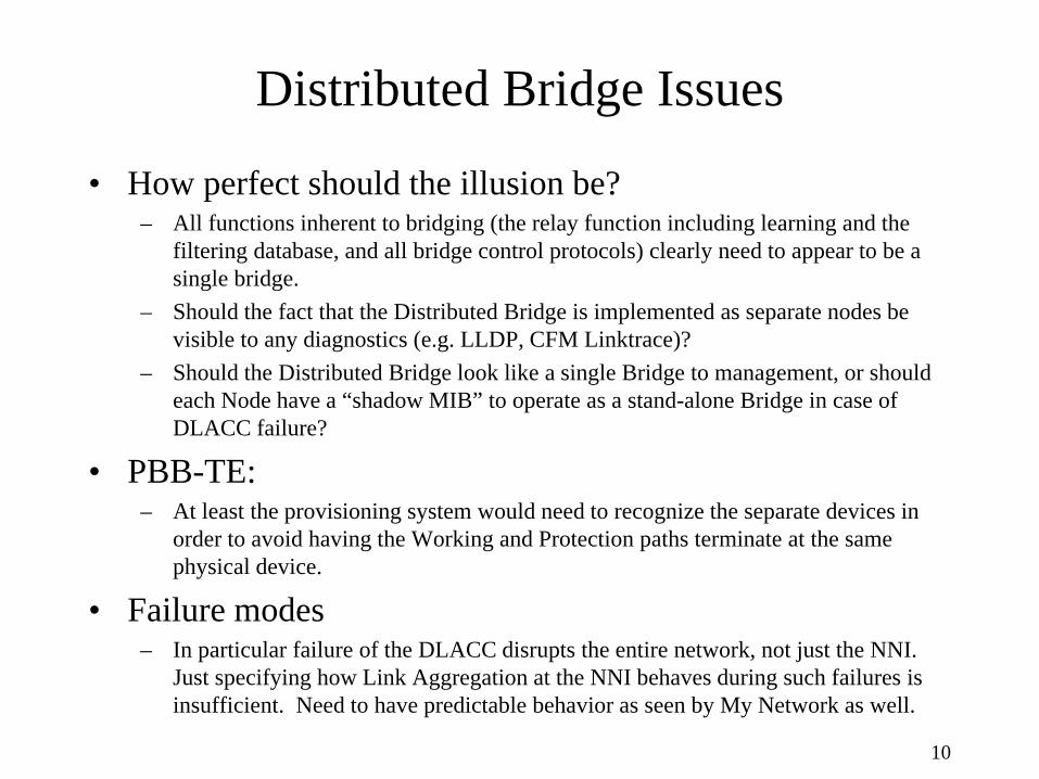
• How perfect should the illusion be?– All functions inherent to bridging (the relay function including learning and the
filtering database, and all bridge control protocols) clearly need to appear to be a single bridge.
– Should the fact that the Distributed Bridge is implemented as separate nodes be visible to any diagnostics (e.g. LLDP, CFM Linktrace)?
– Should the Distributed Bridge look like a single Bridge to management, or should each Node have a “shadow MIB” to operate as a stand-alone Bridge in case of DLACC failure?
• PBB-TE: – At least the provisioning system would need to recognize the separate devices in
order to avoid having the Working and Protection paths terminate at the same physical device.
• Failure modes– In particular failure of the DLACC disrupts the entire network, not just the NNI.
Just specifying how Link Aggregation at the NNI behaves during such failures is insufficient. Need to have predictable behavior as seen by My Network as well.
10

Distributed Bridge Model
11
MAC MACMAC MAC MAC MAC
Higher Layer Entities
Relay Relay
Higher Layer Entities
Link Aggregation Link AggregationDistributed
Link Aggregation
Distributed Relay
Distributed Higher Layer Entities
• Emulate a single bridge • Create illusion that there is a single relay, single instance of all higher layer entities,
and a single Bridge Port representing entire Distributed Link Aggregation Group.
• In normal operation neither the NNI nor My Network can distinguish this from a single bridge.
• Failure of the DLACC (“split brain” scenario) potentially causes a significant change in operation as viewed from My Network.
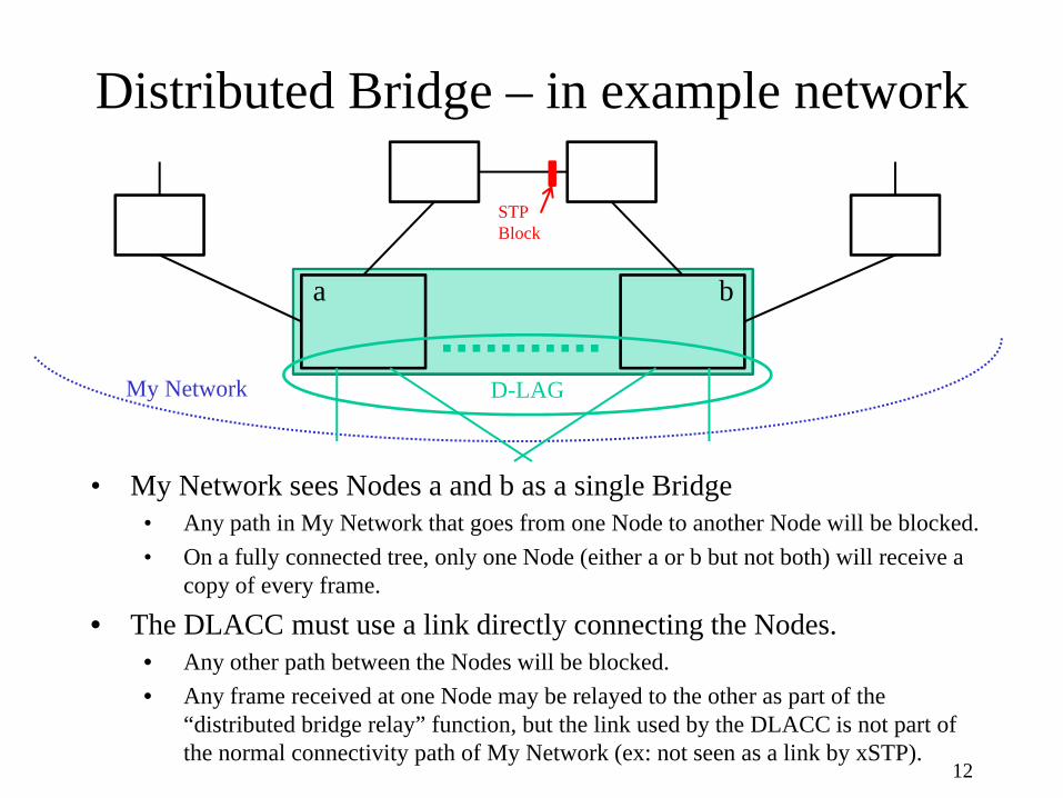
Distributed Bridge – in example network
12
D-LAGMy Network
a b
• My Network sees Nodes a and b as a single Bridge• Any path in My Network that goes from one Node to another Node will be blocked.• On a fully connected tree, only one Node (either a or b but not both) will receive a
copy of every frame.
• The DLACC must use a link directly connecting the Nodes.• Any other path between the Nodes will be blocked.• Any frame received at one Node may be relayed to the other as part of the
“distributed bridge relay” function, but the link used by the DLACC is not part of the normal connectivity path of My Network (ex: not seen as a link by xSTP).
STPBlock
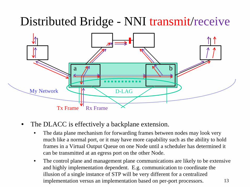
Distributed Bridge - NNI transmit/receive
13
D-LAGMy Network
Tx Frame Rx Frame
• The DLACC is effectively a backplane extension.• The data plane mechanism for forwarding frames between nodes may look very
much like a normal port, or it may have more capability such as the ability to hold frames in a Virtual Output Queue on one Node until a scheduler has determined it can be transmitted at an egress port on the other Node.
• The control plane and management plane communications are likely to be extensive and highly implementation dependent. E.g. communication to coordinate the illusion of a single instance of STP will be very different for a centralized implementation versus an implementation based on per-port processors.
a b
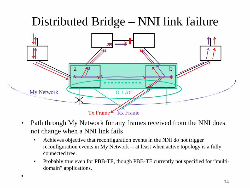
Distributed Bridge – NNI link failure
14
D-LAGMy Network
Tx Frame Rx Frame
• Path through My Network for any frames received from the NNI does not change when a NNI link fails
• Achieves objective that reconfiguration events in the NNI do not trigger reconfiguration events in My Network -- at least when active topology is a fully connected tree.
• Probably true even for PBB-TE, though PBB-TE currently not specified for “multi-domain” applications.
•
a b

Distributed Bridge – DLACC failure
15
• Both Nodes cannot continue to operate with the same identity (Bridge ID, etc.) when the DLACC fails (“split brain” scenario).
• Requires reliable detection of DLACC failure.
• Allowable operational modes include:1. Both Nodes change to different, unique identity.2. Preferred Node maintains the same identity if it is up; the other Node …”
a) Always changes identity.b) Maintains same identity if Preferred Node down, otherwise changes identity.*c) Maintains same identity if Preferred Node down, otherwise goes down.*
*2b and 2c require reliable distinction between a DLACC failure versus a Node failure.
D-LAGMy Network
Tx Frame Rx Frame
a b
Distributed Port Model
16
Distributed Port Model
• The Distributed Port Model proposes that some set of ports on two or more Bridges can appear to be a single Bridge Port on a single Bridge.– The illusion of a single Bridge is only presented to the NNI. The
rest of the network continues to see multiple distinct Bridges.– Goal is to confine everything necessary to create the illusion in the
Link Aggregation sublayer. All other bridge functionality is unchanged and operates independently in each of the Bridges.
• This may prove to be optimistic. For instance it may be necessary to “play games” with how Spanning Tree operates on the ports involved in the Distributed LAG. The fallback goal is that Spanning Tree operation on the other Bridge Ports is not changed.
– Failure modes of the Distributed LAG, including DLACC failure, would impact the NNI but not the rest of My Network !!!
• This is a huge advantage over the Distributed Bridge Model.• Also has less impact on My Network when D-LAGs are dynamically formed
or dissolved. 17
Distributed Port Model
18
Link Aggregation
MAC MAC
Higher Layer Entities
Relay
MAC
Higher Layer Entities
Relay
MAC
Link Aggregation
MAC MAC
DistributedLink Aggregation
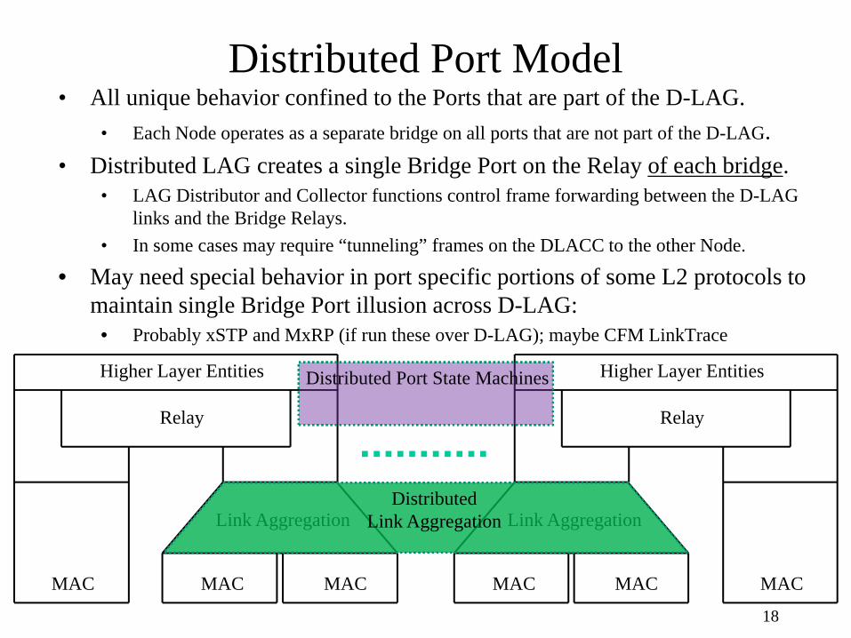
• All unique behavior confined to the Ports that are part of the D-LAG.• Each Node operates as a separate bridge on all ports that are not part of the D-LAG.
• Distributed LAG creates a single Bridge Port on the Relay of each bridge.• LAG Distributor and Collector functions control frame forwarding between the D-LAG
links and the Bridge Relays.• In some cases may require “tunneling” frames on the DLACC to the other Node.
• May need special behavior in port specific portions of some L2 protocols to maintain single Bridge Port illusion across D-LAG:
• Probably xSTP and MxRP (if run these over D-LAG); maybe CFM LinkTrace
Distributed Port State Machines

Distributed Link Aggregation Model
19
• Distributed LAG adds a Gateway function in LAG sublayer of each Node• My Network selects one node as the Active Gateway for each VID.• My Network and Other Network may agree on a designated link for each service instance.
• Otherwise My Network selects designated transmission link per service instance.
• Transmit frames passed to Distributor at Active Gateway Node, discarded at inactive Gateway.• If designated link on Node w/inactive Gateway, Tx frames “tunneled” to Active Gateway Node Distributor.
• Received frames from Collector are passed up the interface stack on Node with Active Gateway.• If received on a link on the Node w/inactive Gateway, Rx frames “tunneled” to Active Gateway.
Distributor
Collector Collector
Distributor
Gateway ?? ?
MAC
? Gateway
MAC MAC MAC
Distributed Port – in example network
20
D-LAGMy Network
a b
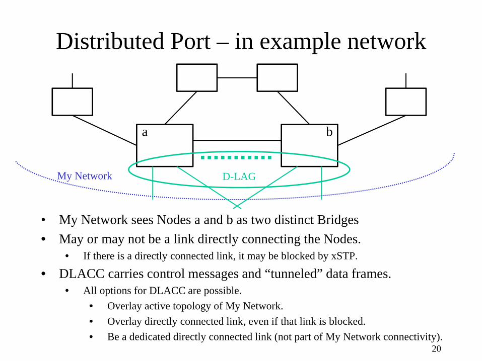
• My Network sees Nodes a and b as two distinct Bridges• May or may not be a link directly connecting the Nodes.
• If there is a directly connected link, it may be blocked by xSTP.
• DLACC carries control messages and “tunneled” data frames.• All options for DLACC are possible.
• Overlay active topology of My Network.• Overlay directly connected link, even if that link is blocked.• Be a dedicated directly connected link (not part of My Network connectivity).
Distributed Port Model
21
Case a) Data flows when either:-- there is no direct link between D-LAG nodes, or -- the direct link is blocked (e.g. by xSTP).
(look at this case first because it most clearly shows need for the Gateway)
Distributed Port - transmit/receive
22
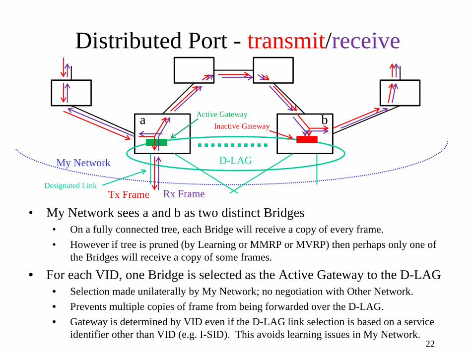
• My Network sees a and b as two distinct Bridges• On a fully connected tree, each Bridge will receive a copy of every frame.• However if tree is pruned (by Learning or MMRP or MVRP) then perhaps only one of
the Bridges will receive a copy of some frames.
• For each VID, one Bridge is selected as the Active Gateway to the D-LAG• Selection made unilaterally by My Network; no negotiation with Other Network.• Prevents multiple copies of frame from being forwarded over the D-LAG.• Gateway is determined by VID even if the D-LAG link selection is based on a service
identifier other than VID (e.g. I-SID). This avoids learning issues in My Network.
D-LAGMy Network
Tx Frame Rx Frame
a bInactive GatewayActive Gateway
Designated Link
Distributed Port - receive on wrong link
23
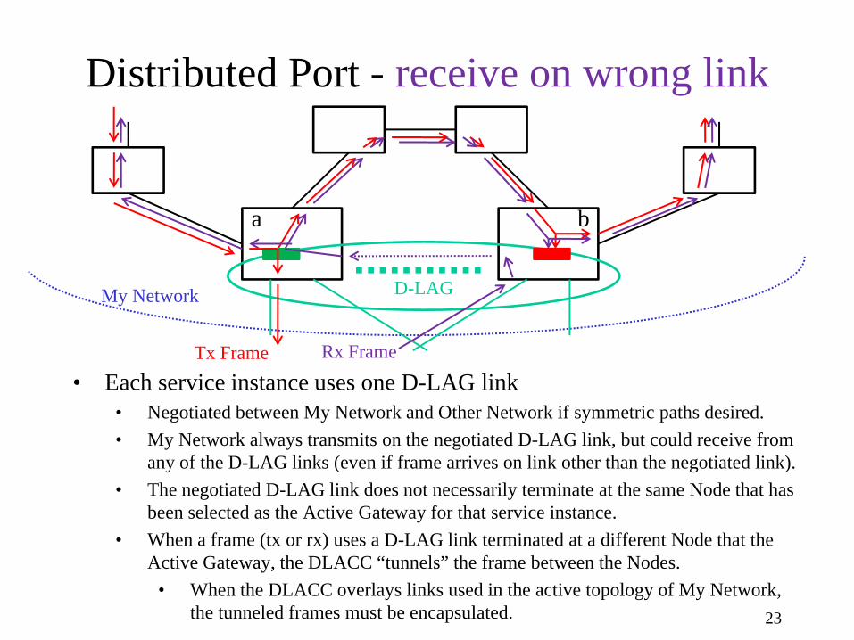
• Each service instance uses one D-LAG link• Negotiated between My Network and Other Network if symmetric paths desired.• My Network always transmits on the negotiated D-LAG link, but could receive from
any of the D-LAG links (even if frame arrives on link other than the negotiated link).• The negotiated D-LAG link does not necessarily terminate at the same Node that has
been selected as the Active Gateway for that service instance.• When a frame (tx or rx) uses a D-LAG link terminated at a different Node that the
Active Gateway, the DLACC “tunnels” the frame between the Nodes.• When the DLACC overlays links used in the active topology of My Network,
the tunneled frames must be encapsulated.
D-LAGMy Network
Tx Frame Rx Frame
a b
Distributed Port - link failure
24
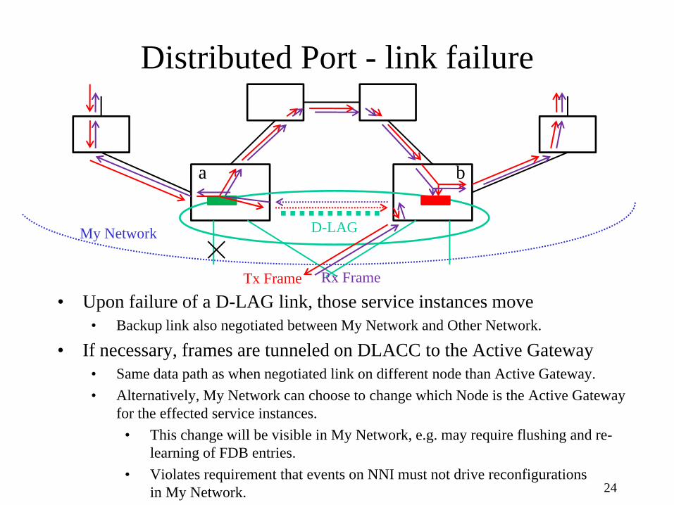
• Upon failure of a D-LAG link, those service instances move• Backup link also negotiated between My Network and Other Network.
• If necessary, frames are tunneled on DLACC to the Active Gateway• Same data path as when negotiated link on different node than Active Gateway.• Alternatively, My Network can choose to change which Node is the Active Gateway
for the effected service instances.• This change will be visible in My Network, e.g. may require flushing and re-
learning of FDB entries.• Violates requirement that events on NNI must not drive reconfigurations
in My Network.
D-LAGMy Network
Tx Frame Rx Frame
a b

Distributed Port - DLACC failure
25
• In theory DLACC won’t fail unless My Network partitions• Because in theory DLACC can overlay the active topology of My Network.• Whether this is practical is another question.
• Assume DLACC depends upon a direct connection that has failed.• All ports on both Nodes that are not involved in the D-LAG continue to operate.
This minimizes impact on My Network.• The D-LAG cannot be maintained, so the D-LAG ports on one Node go down.
• Norm has a proposal for how to accomplish this in LACP.• Effectively moves the Gateway for every service to one Node, which has
impact in My Network (may cause FDB flushes, etc).
D-LAGMy Network
Tx Frame Rx Frame
a b
Distributed Port Model
26
Case b) Data flows when:-- there is a direct link between D-LAG nodes, and -- the direct link is not blocked (e.g. by xSTP).
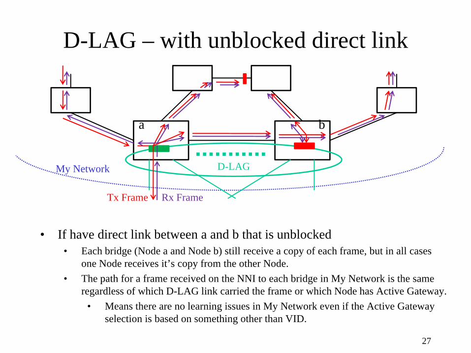
D-LAG – with unblocked direct link
27
D-LAGMy Network
Tx Frame Rx Frame
• If have direct link between a and b that is unblocked• Each bridge (Node a and Node b) still receive a copy of each frame, but in all cases
one Node receives it’s copy from the other Node.• The path for a frame received on the NNI to each bridge in My Network is the same
regardless of which D-LAG link carried the frame or which Node has Active Gateway.• Means there are no learning issues in My Network even if the Active Gateway
selection is based on something other than VID.
a b

D-LAG w/direct – link failure
28
D-LAGMy Network
Tx Frame Rx Frame
• If have direct link between a and b that is unblocked• When the designated D-LAG link and the Active Gateway are on different Nodes,
get “hairpinning” where every frame exchanged between Nodes twice.• Exchanged once on active topology.• Exchanged once when tunneled on DLACC
a b
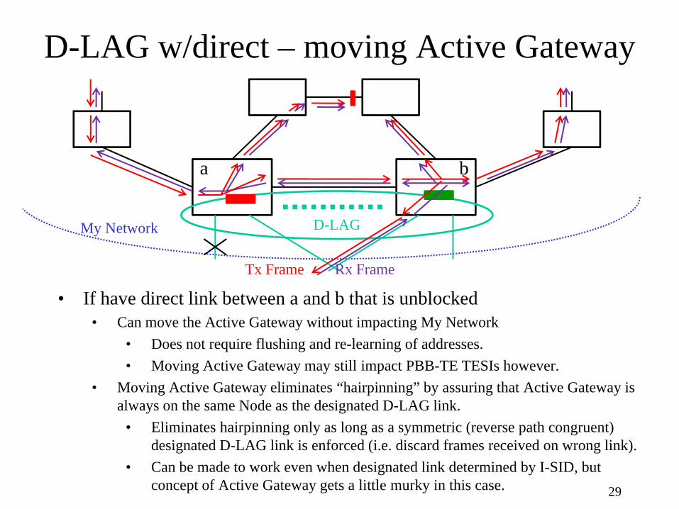
D-LAG w/direct – moving Active Gateway
29
D-LAGMy Network
Tx Frame Rx Frame
• If have direct link between a and b that is unblocked• Can move the Active Gateway without impacting My Network
• Does not require flushing and re-learning of addresses.• Moving Active Gateway may still impact PBB-TE TESIs however.
• Moving Active Gateway eliminates “hairpinning” by assuring that Active Gateway is always on the same Node as the designated D-LAG link.
• Eliminates hairpinning only as long as a symmetric (reverse path congruent) designated D-LAG link is enforced (i.e. discard frames received on wrong link).
• Can be made to work even when designated link determined by I-SID, but concept of Active Gateway gets a little murky in this case.
a b
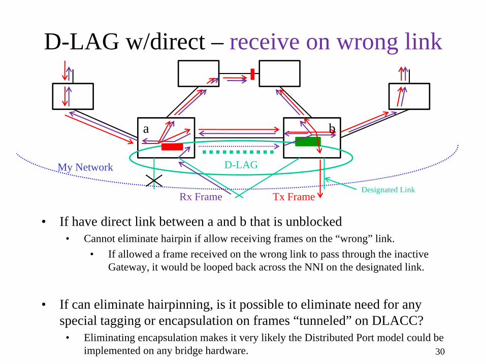
D-LAG w/direct – receive on wrong link
30
D-LAGMy Network
Tx FrameRx Frame
• If have direct link between a and b that is unblocked• Cannot eliminate hairpin if allow receiving frames on the “wrong” link.
• If allowed a frame received on the wrong link to pass through the inactive Gateway, it would be looped back across the NNI on the designated link.
• If can eliminate hairpinning, is it possible to eliminate need for any special tagging or encapsulation on frames “tunneled” on DLACC?
• Eliminating encapsulation makes it very likely the Distributed Port model could be implemented on any bridge hardware.
a b
Designated Link
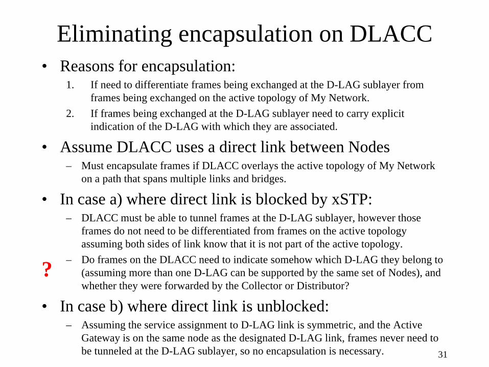
Eliminating encapsulation on DLACC• Reasons for encapsulation:
1. If need to differentiate frames being exchanged at the D-LAG sublayer from frames being exchanged on the active topology of My Network.
2. If frames being exchanged at the D-LAG sublayer need to carry explicit indication of the D-LAG with which they are associated.
• Assume DLACC uses a direct link between Nodes– Must encapsulate frames if DLACC overlays the active topology of My Network
on a path that spans multiple links and bridges.
• In case a) where direct link is blocked by xSTP:– DLACC must be able to tunnel frames at the D-LAG sublayer, however those
frames do not need to be differentiated from frames on the active topology assuming both sides of link know that it is not part of the active topology.
– Do frames on the DLACC need to indicate somehow which D-LAG they belong to (assuming more than one D-LAG can be supported by the same set of Nodes), and whether they were forwarded by the Collector or Distributor?
• In case b) where direct link is unblocked:– Assuming the service assignment to D-LAG link is symmetric, and the Active
Gateway is on the same node as the designated D-LAG link, frames never need to be tunneled at the D-LAG sublayer, so no encapsulation is necessary. 31
?
Distributed Port Model
32
Issues with Distributing port specific shimsand port specific processes on “higher layer entities”

Distributed Port STP Problem Statement
33
D-LAG
BPDU
a b
Root
LAG
BPDUBPDUDoes not Rxany BPDUs
Blocks entire LAGdue to Dispute
• For a non-distributed LAG, entire LAG treated as a single Bridge Port• Single Spanning Tree Port Role and Port State for entire LAG.• Single BPDU sent, which ends up on just one of the LAG links.
• If each Node of a Distributed LAG runs Spanning Tree separately:• Nodes may determine different Port Role and Port State for the same D-LAG.• BPDUs sent from each Node (which looks like a shared LAN to the receiving LAG).• One Node may not receive any BPDUs from LAG, so it has incomplete information.
• Can produce undesirable results, such as that shown below:
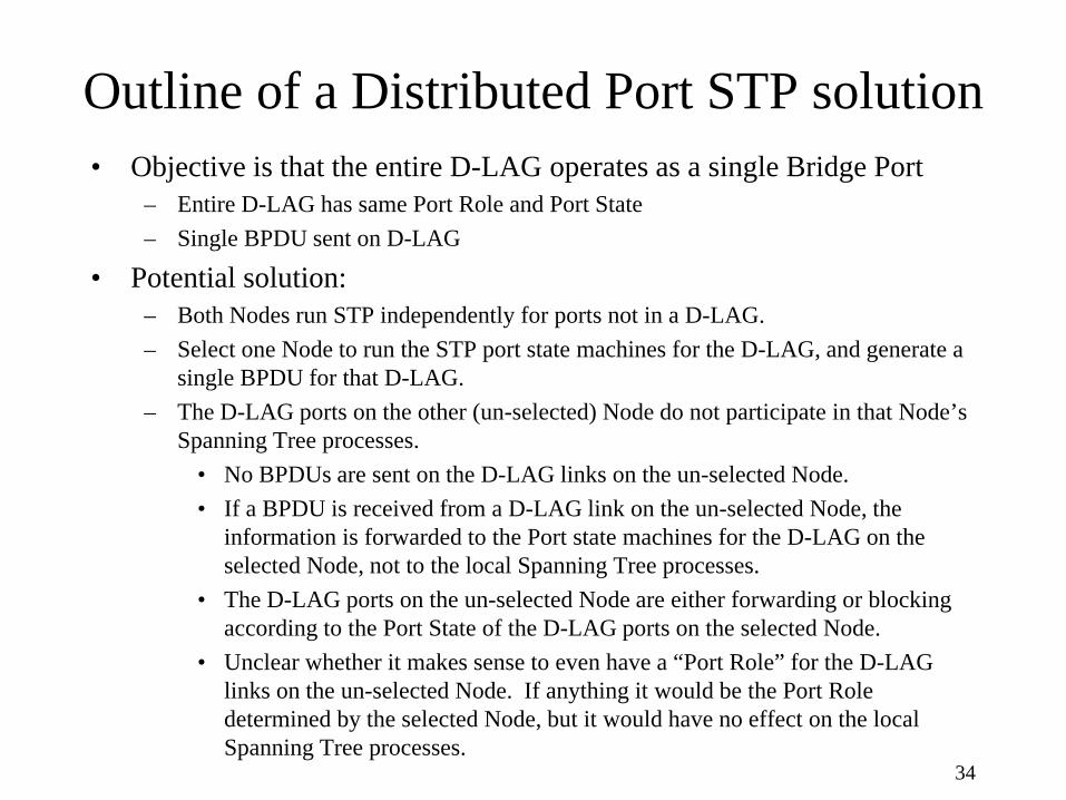
Outline of a Distributed Port STP solution• Objective is that the entire D-LAG operates as a single Bridge Port
– Entire D-LAG has same Port Role and Port State– Single BPDU sent on D-LAG
• Potential solution:– Both Nodes run STP independently for ports not in a D-LAG.– Select one Node to run the STP port state machines for the D-LAG, and generate a
single BPDU for that D-LAG.– The D-LAG ports on the other (un-selected) Node do not participate in that Node’s
Spanning Tree processes.• No BPDUs are sent on the D-LAG links on the un-selected Node.• If a BPDU is received from a D-LAG link on the un-selected Node, the
information is forwarded to the Port state machines for the D-LAG on the selected Node, not to the local Spanning Tree processes.
• The D-LAG ports on the un-selected Node are either forwarding or blocking according to the Port State of the D-LAG ports on the selected Node.
• Unclear whether it makes sense to even have a “Port Role” for the D-LAG links on the un-selected Node. If anything it would be the Port Role determined by the selected Node, but it would have no effect on the local Spanning Tree processes.
34
Distributed Port Model
35
Difference between Distributed LAG for a NNI and a generalized Distributed LAG solution

NNI D-LAG vs. Generalized D-LAG
• D-LAG link selection:– NNI D-LAG
• assumes link selection based on service instance.• accomodates, and perhaps requires, the link selection is negotiated between
My Network and Other Network to be symmetric.
– Generalized D-LAG• Distributor unilaterally makes link selection on any criteria it chooses• Can never assume symmetric paths
• Control Protocols:– NNI D-LAG
• May be able to assume that xSTP (and MVRP?) are not running across NNI, and therefore not operational on D-LAG.
– Generalized D-LAG• Must be able to support xSTP and MVRP on D-LAG.
36
Conclusions
37
What, if anything, needs to be standardizedout of all of this?

Both Models have advantages
• Distributed Bridge– In normal operation, the fact that the Bridge is distributed is not
visible to either My Network or the NNI.– How existing protocols (xSTP, MxRP, etc.) should work in this
environment is clear and intuitive.– Many existence proofs of concept.
• Distributed Port– Each Node looks like a normal, stand-alone Bridge to My
Network. This does not change in the event of a DLACC failure.– May be easier to support overlapping D-LAGs
• (e.g. D-LAG 1 between Nodes a and b, D-LAG 2 between Nodes b and c, without having to make Nodes a and b and c all look like a single Bridge.)
– May not require any special encapsulation of data frames on the DLACC.
38

Reasons for Standardization1. If any new or different behavior needs to be specified for Bridges
that are not D-LAG Nodes to interoperate with the D-LAG Nodes.– Haven’t identified anything essential here. That’s not surprising since several
vendors have been able to introduce proprietary Distributed LAG solutions.– Norm has some proposals for assisting in “split brain” detection and failover.
2. If there are implementation options we want to constrain, or simply describe, because they result in observable behavioral differences.
– Potentially several things to specify in this category. It makes both vendors and customers aware of the trade-offs of various implementation decisions. It also avoids making every vendor re-invent a solution, which may help avoid implementations with poor behavior that would give the standard a bad name.
3. If we want to support multi-vendor interoperability within a Distributed LAG.
– May yet want to consider this. For example the Distributed Port model would be much simpler to specify in a standard than the Distributed Bridge model, and case a) of that model supports over-lapping D-LAGs. If we decided this support was important it would get more difficult to argue that all bridges in all of the D-LAGs would come from the same vendor.
39

Recommendations• Both the Distributed Bridge and Distributed Port models have pros and
cons. Both should be allowed (assuming we pursue the Distributed LAG approach for a Resilient Network Interconnect standard).
• The concept of the Distributed Bridge model should be described in the standard, but the details should not be specified.
– Every aspect of a Bridge needs to be distributed, and that involves lots of trade-offs and design decisions. Finding common ground here would be a huge project.
– The advantages of the Distributed Bridge model get stronger as the implementation gets more proprietary (e.g. managed as a single device even through a CLI, making the DLACC an extension of a switch fabric rather than a port on the fabric, etc.)
• The Distributed Port model should also be described in the standard.– We should consider describing the trade-offs and resultant behavioral differences
of some design decisions (such as whether or not to depend upon an unblocked direct link).
– T.B.D whether certain design decisions should be constrained.
40