residual stresses induced by hole cold r. cook, p. …€¦ · residual stresses induced by hole...
TRANSCRIPT

Residual stresses induced by hole cold
expansion
R. Cook, P. Holdway
Materials and Structures Department, Defence
Research Agency, Farnborough, Hampshire, UK
ABSTRACT
This paper describes an X-ray diffraction technique for measuring residualstresses. The results of measurements at locations in the vicinity of plain andcold expanded holes in an aluminium alloy are presented. Residual stresses areshown to vary significantly in all three dimensions and two dimensionalanalyses commonly used for residual stress determination are shown to beinadequate. The results of a fatigue test programme are also presented inwhich simple aluminium alloy specimens containing plain and cold expandedholes were subjected to constant amplitude fatigue loading. The results showthat cracks from plain holes continuously increase in growth rate to failurewhilst cracks from cold expanded holes decrease in growth rate and frequentlyarrest. The arrested crack lengths are different on either face of the coldexpanded specimens and this is equated to the different residual stress fieldspresent. Fatigue crack growth rates predicted using a Green's functiontechnique are compared with those measured experimentally.
INTRODUCTION
Cold expansion of holes is a technique widely used to extend the endurance ofairframe structures. In general, the improvements in endurance due to coldexpansion are not determined for design life purposes and can only therefore beconsidered as an insurance that the design life will be achieved in service. Thissituation arises primarily from an inability to reliably predict the fatigueendurance of structures containing cold expanded holes. More extensive use ofcold expansion as a manufacturing process will only be possible whenimprovements in the fatigue endurance of structures due to cold expansion ofholes can be accurately predicted.
Damage tolerant design requires the prediction of the rate of growth ofcracks from assumed initial flaw sizes to lengths which can be reliably detectedduring periodic inspections. For cold expanded holes, stress intensity factorsmust be calculated to account for both applied and residual stresses. It is theaim of this investigation to assess a method of determining residual stresses anda method of calculating the resultant stress intensity factor distribution.Residual stresses have been measured around both plain and cold expandedholes using an X-ray diffraction technique. This technique has previously beenused to measure residual stresses around fastener holes in steel [1] and more
© British Crown
Transactions on Engineering Sciences vol 2, © 1993 WIT Press, www.witpress.com, ISSN 1743-3533

92 Surface Treatment Effects
recently in 7050 Aluminium alloy [2]. The X-ray diffraction technique has theadvantage of being non-destructive but due to the relatively low penetrationdepth of X-rays (30(im with Cu radiation), only measures surface stresses. Theresults of these measurements are used to explain the crack growth behaviourobserved in an experimental study. Crack growth rates are predicted using themeasured residual stress data in a Green's function technique, and comparedwith experimental measurements.
FATIGUE TEST PROGRAMME
A fatigue test programme was carried out to determine the effect of coldexpansion on the fatigue crack initiation period and on crack propagation ratesin 7050-T76 aluminium alloy. Fatigue tests were performed at a stress ratio R of0.1 with a peak nett section stress of 184 MPa. Tests were stopped at regularintervals and acetate replicas made of the specimen surfaces. Cracks from plainhole specimens continuously increased in growth rate to failure whilst in coldexpanded specimens cracks grew rapidly through the thickness of the specimenand soon arrested. Cracks remained at the arrested length for a considerableperiod before rapid failure or remote failure occurred.
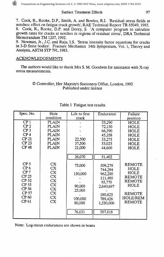
Fatigue endurances and lives to first observed crack are given in Table 1. Acomparison of the log mean endurances shows that cold expansion extends thefatigue endurance of these specimens by a factor of about 10. The increase ininitiation time, however, is only by a factor of about 3. The main effect of coldexpansion at this stress level is to reduce the crack propagation life. Theremainder of this Report will therefore concern crack propagation behaviour.
Crack growth rates were calculated using a seven point incrementalpolynomial method. Results from plain hole specimens are presented as symbolsin Fig.l; the solid curves are data predicted using techniques described in thefollowing section. Crack growth rates for cold expanded hole specimens arepresented as symbols in Fig. 2. Cracks on the outlet face grew to lengths ofbetween 0.1 and 0.3mm and then arrested while cracks on the inlet face grew tolengths of between 0.8 and 1.3mm and then arrested. Specimens which failedfrom sites remote from the test section were subsequently statically pulled tofailure to examine the arrested crack profiles. A typical example is shown inFig. 3.
RESIDUAL STRESS MEASUREMENTS
Residual stress measurements were carried out using a Siemens D500diffractometer equipped with a Position Sensitive Detector (PSD) and an X-Ystage. Cu k, radiation at 40kV, 40mA was used and the X-ray beam wascollimated to "give an irradiated area of approximately 1 x 1.5mml The centre ofthis rectangle was taken as the position of the beam. Initial alignment of thebeam relative to the hole edge was carried out by eye with the aid of afluorescent disk. Subsequent movements were then carried out usingmicrometer screw gauges. The sin" \j/ method [3,41 was used for residual stressmeasurements employing up to 15 \j/ tilts with ±2 oscillations at each tilt. The(422) peak at 137.5° 26 was used and measured strains were converted tostresses using values of Young's modulus and Poisson's ratio of 72 GPa and 0.34respectively.
Transactions on Engineering Sciences vol 2, © 1993 WIT Press, www.witpress.com, ISSN 1743-3533

Surface Treatment Effects 93
Residual stress measurements were carried out on both lightly ground andmechanically polished surfaces. Grinding was carried out to remove the burringfound at the edge of the hole. Residual stress measurements [5] suggested thatthe difference between the two surface finishes was less than the errors in theindividual measurements.
The radial and hoop residual stresses at four 90° locations around a 4% cold-expanded hole have been measured on a number of samples and a typical set forthe mandrel outlet side are shown in Table 2. Position C corresponds to thesleeve-gap location. The radial stresses were compressive at the hole edge,increased away from the hole before decreasing again. The maximum radialresidual stresses occurred between 1.5 and 2.5mm from the hole with those at Cbeing greater than at other positions. The hoop stresses were a maximum at orclose to the hole edge and became tensile at about 3.0mm from the hole. Themaximum stresses were again found at C with the smallest stresses diametricallyopposite at A. Stresses at B and D were intermediate of those at A and C.During the fatigue test programme position C was on the centreline of thespecimen, thus cracking occurred at locations B and D. Repeat measurementswere generally ±2 MPa at a particular position but varied by between 20 and 50MPa for equivalent positions in different samples with the same degree of coldexpansion.
Fig. 4 shows some representative plots from the mandrel inlet and outletfaces for a radial and hoop direction. Residual stresses were found to be greateron the outlet face compared to the inlet face at the same position around thehole. Differences were larger in the hoop direction than the radial directionclose to the hole edge (< 2.0mm). The hoop stress distributions shown (positionD) are the ones used in the prediction routines described later.
Fig. 4 also shows some representative results from a plain hole, at twolocations 90° apart. The radial stresses showed a slight increase at the hole edgewhereas the hoop stresses were much smaller and both were close to zero afterabout 2.0mm distance. For prediction purposes it is therefore assumed that thehoop residual stresses in plain hole specimens are negligible.
PREDICTION OF FATIGUE CRACK GROWTH RATES
Prediction methodThe prediction method used requires a knowledge of the stress intensity factoras a function of the crack length and the total stress (applied plus residual), andthe relationship between stress intensity factor and crack growth rate for thematerial being tested. The general method consists of determining the residualand applied stress distributions and summing them to give a total stressdistribution. Stress intensity factors can be derived for through the thicknesscracks at the edge of a hole in an infinite sheet using a Green's function derivedby Shivakumar and Forman [6], Crack growth rates can be determined from thestress intensity factors using a materials database. Details of the method usedare given in Ref 7.
Predictions for plain holesThe prediction routine was programed on a computer and is described in Ref. 8.The program was tested by performing predictions of crack growth rates forplain hole specimens and comparing them with experimental data. Cracks grew
Transactions on Engineering Sciences vol 2, © 1993 WIT Press, www.witpress.com, ISSN 1743-3533

94 Surface Treatment Effects
in the plain hole specimens as single or double corner cracks and single ordouble through the thickness cracks. Corrections were therefore required to thestress intensity factors derived in the program as the Green's function used wasappropriate to symmetric through the thickness cracks. Corrections werederived from the work of Newman and Raju [9] and added to the computerprogram. Predictions were made for the experimentally observed crackingconditions. The slowest rates were predicted for a single corner crack growingthrough the plate and becoming a single through the thickness crack. The fastestrates were predicted for a double through the thickness crack. These twopredictions are shown in Fig. 1, and form an envelope which encloses most ofthe experimental data. This gives some confidence in the proposed approach.
Predictions for cold expanded holesThe residual stresses contributing to the Mode I stress intensity factor are thehoop stresses at the crack locations, i.e. positions B and D of residual stressmeasurement. It was observed earlier that stresses at these locations on theinlet face were markedly different from those on the outlet face, especially in thevicinity of the hole. Predictions of inlet and outlet face stress intensities aretherefore considered separately. X-ray measurements were made as close to thehole as possible with the beam size chosen . This means that the hoop stressvalues in the vicinity of the hole are averaged over -1mm which 'smears' out anysteep stress gradients and leads to an underestimate of the residual stress. Fromthe finite element results, this region was shown to have yielded in compression,as indicated by the reversal in slope of the residual stresses near to the hole (Fig.5). It was decided to impose this behaviour on the measured residual stresses inorder to allow predictions of crack growth rates in this region. The residualstress in the compression yielded zone were simply scaled by the peakcompressive stress and added to the measured distributions as indicated by thedotted lines in Fig. 5. Predictions of crack growth rates were made using thedistributions shown in Fig. 5 for the inlet and outlet faces of the specimen, andusing the finite element solution.
The profiles of arrested cracks were measured from fatigue tests in whichremote failure had occurred, a typical example is shown in Fig. 3. It can be seenthat cracks on the inlet face were approximately quarter circular in shape whilstthose on the outlet face were approximately through the thickness cracks. In theprediction routines, corrections were made to the stress intensity factor solutionto allow for these observed crack shapes. The results of the predictions areshown as solid curves in Fig. 2 for the inlet and outlet faces; the finite elementresults predicted that cracks would not grow. The agreement with experimentaldata is poor, but crack retardation is predicted at about the correct crack lengthfor the inlet face where a minimum in the crack rate is predicted at a cracklength of about 1mm. It was expected that predicted rates would be faster thanthose measured as the magnitude of the measured compressive residual stresswas thought to be underestimated, owing to the difficulty in making X-raydiffraction measurements in the steep stress gradient close to the hole, asalready discussed.
Based on the assumption that the true hoop stresses were more compressivethan those measured, further predictions were made using more compressivestresses adjacent to the hole. Stress distributions for inlet and outlet faces wereused which maintained the overall shape of the measured distributions and alsomaintained the difference in compressive stresses between inlet and outlet faces
Transactions on Engineering Sciences vol 2, © 1993 WIT Press, www.witpress.com, ISSN 1743-3533
Surface Treatment Effects 95
at a distance of 0.5mm from the hole. It was found that by increasing themaximum compressive residual stress of measured inlet and outlet facedistributions by 75 MPa and adding the compressively yielded zone resulted inpredictions close to the measured data. These predictions are shown as dottedlines in Fig. 2.
DISCUSSION
The X-ray diffraction method described was found to be suitable for measuringsurface residual stresses. However, because these stresses were averaged overthe irradiated volume, it was not possible to resolve the steep stress gradients inthe vicinity of the hole. Reducing the irradiated volume will result in poorer dataquality unless the count times are significantly increased. It may also lead toproblems if the irradiated volume becomes the same as the grain size. Texture inthe plate will also give rise to errors in residual stresses due to anisotropicmechanical properties. Measurments showed that residual stresses in the hoopdirection, which affect Mode I fatigue crack growth rates, were significantly lesscompressive on the mandrel inlet face than on the outlet face of cold expandedspecimens. This was supported by experimental crack growth observationswhere the extent of crack growth was greater on the mandrel inlet face than onthe outlet face. The X-ray measurements also showed a variation in hoop andradial stresses at locations around the circumference of the hole on both inletand outlet faces. The least compressive hoop stress, i.e. the most fatigue criticallocation, was found diametrically opposite the sleeve-gap position. In structuralcomponents it would be preferrable to align the sleeve-gap with the mainloading direction in order to avoid the fatigue critical hole location occurring atthe point of maximum stress.
The two dimensional finite element analysis, by its nature, cannot indicateresidual stress variations around the circumference of a hole nor through thethickness of a component. The residual stresses resulting from the FE analysiswere much more compressive in the hoop direction close to the hole than thosemeasured, typically by a factor of two. This resulted in no crack growth beingpredicted when the Green's function model was used. Whilst it cannot beconcluded that the magnitude of the compressive hoop stress predicted by theFE analysis is too large, the measurements and predictions suggest that this maybe the case. This is not a fault of the FE method, but of the assumptions made inthis particular application. A full three dimensional FE analysis is clearlyrequired to model the complete cold expansion process. The through thethickness variation in hoop residual stresses resulting from such an analysiscould aid in explaining the crack shapes observed in tests.
Cold expansion of open holes in simple specimens was shown to give asignificant improvement in fatigue endurance over specimens with plain holes.The improvements comprised a threefold increase in the crack initiation period,but a seventeenfold increase in the crack propagation period. The crackpropagation period in cold expanded specimens was very long because cracksgrew and then arrested for a significant period prior to failure. The stress levelused was close to the fatigue limit for cold expanded holes and at higher appliedstress levels cracks would be expected to slow in growth rate but not arrest,leading to smaller fatigue life improvements due to cold expansion. In aircraftstructures stress levels are relatively low and hence crack growth behavioursimilar to that observed in this investigation is expected. This has an important
Transactions on Engineering Sciences vol 2, © 1993 WIT Press, www.witpress.com, ISSN 1743-3533

96 Surface Treatment Effects
bearing on service inspections where relatively shallow through the thicknesscracks will need to be detected. The life of such structures will probably begoverned by the ability of these arrested cracks to re-initiate, which should bethe subject of further studies.
The prediction method adopted in this investigation appears promising. Themain difficulty with predictions is in accurately defining the residual stress fieldspresent. A number of practical and analytical programmes are beingundertaken to produce this information. There are however, a number oflimitations to the prediction method with regard to the redistribution of residualstresses during crack growth and the flank closure of cracks in compressiveresidual stress fields. Both of these aspects are being studied with a view toimproving the prediction program by the incorporation of routines to accountfor these factors.
CONCLUSIONS
1. The present study has shown that X-ray diffraction is a good method fordetermining near surface residual stresses around fastener holes in 7050-T76.However, in the vicinity of the hole where residual stress gradients are high, theaveraging effect of the beam limits the resolution of the technique.
2. Two-dimensional finite element analyses are not suitable for thedetermination of residual stresses surrounding cold expanded holes.
3. At the applied stress levels used in this investigation, cold expansion mainlyaffects the crack propagation period.
4. The fatigue endurance of cold expanded components subjected to stresslevels close to the endurance limit will be governed by the ablility of small cracksto re-initiate.
5. Crack growth prediction using a Green's function technique gave goodagreement with experimental measurements in plain hole specimens andqualitatively predicted the growth behaviour in cold expanded specimens.
REFERENCES
1. Dietrich, G. and Potter, J.M. 'Stress measurements on cold-worked fastenerholes', Advances in X-ray analysis, Vol. 20, p. 321-328,1977.2. Holdway, P. and Bowen, A.W. 'Internal strains near cold-expanded fastenerholes in high-strength 7050 Aluminium alloy plate', In Residual stresses III, Eds.H. Fujiwara, T. Abe and K. Tanaka, Publ. by Elsevier Applied Science London,p. 779,1992.3. Noyan, I.C. and Cohen, J.B. 'Residual stress - Measurement by diffractionand interpretation', Publ. Springer-Verlag, 1987.4. Hawk, V. and Macherauch, E. A useful guide for X-ray stress evaluation',Advanced in X-ray analysis, Vol. 27, p. 81-99, 1983.from a circular hole in aninfinite sheet' Int. J. Fracture, Vol. 16, pp 305-316,5. Holdway, P. Unpublished work.6. Shivakumar, V. and Forman, R.G. 'Green's function for a crack emanating1980.
Transactions on Engineering Sciences vol 2, © 1993 WIT Press, www.witpress.com, ISSN 1743-3533
Surface Treatment Effects 97
7. Cook, R., Rooke, D.P., Smith, A. and Bowles, R.I. 'Residual stress fields atnotches: effect on fatigue crack growth', RAE Technical Report TR 85049,1985.8. Cook, R., Rooke, D.P. and Dorey, S. 'A computer program to calculategrowth rates for cracks at notches in regions of residual stress', DRA TechnicalMemorandum TM 1207,1992.9. Newman, Jr., J.C. and Raju, I.S. 'Stress intensity factor equations for cracksin 3-D finite bodies'. Fracture Mechanics 14th Symposium, Vol. 1, Theory andAnalysis, ASTM STP 791,1983.
ACKNOWLEDGEMENTS
The authors would like to thank Mrs S. M. Goodwin for assistance with X-raystress measurements.
> Controller, Her Majesty's Stationery Office, London, 1993Published under licence
Table 1 Fatigue test results
Spec. No.
CP1CP2CP3CP4CP21CP23CP48
CP5CP6CP7CP25CP32CP55CP56CP57CP60CP61
HoleconditionPLAINPLAINPLAINPLAINPLAINPLAINPLAIN
CXCXCXCXCXCXCXCXCXCX
Life to firstcrack
22,50037,50021,000
26,070 |
75,000
150,000
90,00025,000
100,00080,000
76,631
Endurance
55,29072,15066,59045,35833,27553,02544,600
| 51,402
509,278744,294962,200111,48095,7702,640,697
180,825789,4261,530,000
507,818
FailurepositionHOLEHOLEHOLEHOLEHOLEHOLEHOLE
REMOTEHOLEHOLE
REMOTEREMOTEHOLE
REMOTEHOLE/REMREMOTE
Note: Log-mean endurances are shown in boxes
Transactions on Engineering Sciences vol 2, © 1993 WIT Press, www.witpress.com, ISSN 1743-3533

98 Surface Treatment Effects
TABLE 2 Residual stresses on outlet face of a cold expanded hole
RADIAL STRESSESDISTANCE
(mm)0.51.01.52.02.53.54.55.56.58.5
10.5
POSA
-185±40-226±40-234±42-246±38-210±35-134±37-107140-84±42-45±39-49±36-26±38
HOC0.51.01.52.02.53.54.55.56.58.5
10.5
-246159-208155-146151-86±47-28±4636±4456±4656±5336±4737±4226±45
POSB
-154±40-129±56-195±45-207±47-216146-154146-112141-73143-56142-35143-18144
)P STRESSES (f\-352147-348143-269147-216142-15314081375313640140371383813832137
MPa)POSC
-190146-298143-322141-317139-331139-248137-201139-126140-98135-45139-65141
POSD
-189163-197158-197153-231154-233147-199144-135142-80143-57141-42142-30138
4Pa)-464156-463152-432151-346145-277149-801501714754143591435014845147
-425144-326140-272141-161140-100139171384814157135361362013533141
— Single corner crack becomingsingle through crack
Double through crack
Crtok length * (mm)
Figure 1 Crack growth rates from plain holes
Transactions on Engineering Sciences vol 2, © 1993 WIT Press, www.witpress.com, ISSN 1743-3533

Surface Treatment Effects 99
0 Mandrel outlet face
. Mandrel inlet face
Crack length a (n
Figure 2 Crack growth rates from cold expanded holes
Figure 3 Arrested fatigue cracks
Transactions on Engineering Sciences vol 2, © 1993 WIT Press, www.witpress.com, ISSN 1743-3533

100 Surface Treatment Effects
oQL.
enHoop ARadial A'
***** HOOD B Plain
Radial 8• • • • • In Hoop 8• •••• Out Hoop 3.o_q_oga In Radial COSLQ.OO Out Radial C
-350 j 1 1 1 1 1 1 1 1 1 1 1 1 1 1 1 1 I I 1 1 1 1 1 i 1 1 1 1 1 1 1 1 1 1 1 I I 1 1 j 1 1 1 1 1 1 1 1 1 [ 1 1 1 I T T I I 1 1 1 I T I T T I I I j 1 1 1 1 1 1 1 1 1 ] 1 1 1 1 10 1 2 3 4 5 6 7 8 9
Distance from hole (mm)
Figure 4 Measured residual stress distributions
-650-4
ooooo Inlet Hoop 8ooooo Outlet Hoop. 3& & & & & Finite element HOOD
0 1 2 3 4 5 6 7 8 ^ 9Distance from hole (mm)
1TD
Figure 5 Residual hoop stress distributions used for crack growth predictions
Transactions on Engineering Sciences vol 2, © 1993 WIT Press, www.witpress.com, ISSN 1743-3533