residential electrical inspector (cae) parallel conductors ... · residential electrical inspector...
TRANSCRIPT
Residential Electrical Inspector (CAE)
Parallel Conductors
Lesson 10
Based on the 2014 OESC
Updated: January 2017

2
Code Sections used in this Module
110.3(B) Install per manufacturers instructions
110.14 Temperature and termination adjustment
310.10 Parallel conductor installation
Table 8 Chapter 9
of 29

3 of 29

Parallel Conductors
What is the purpose of using parallel conductors?
Generally, paralleling is used to reduce costs and
installation difficulties associated with large
conductors and raceways. The parallel conductors
can be run in the same raceway or separate
raceways. When 2 conductors of the same size are
paralleled, their ampacity doubles.
4 of 29
5
Circuit
Breaker Load
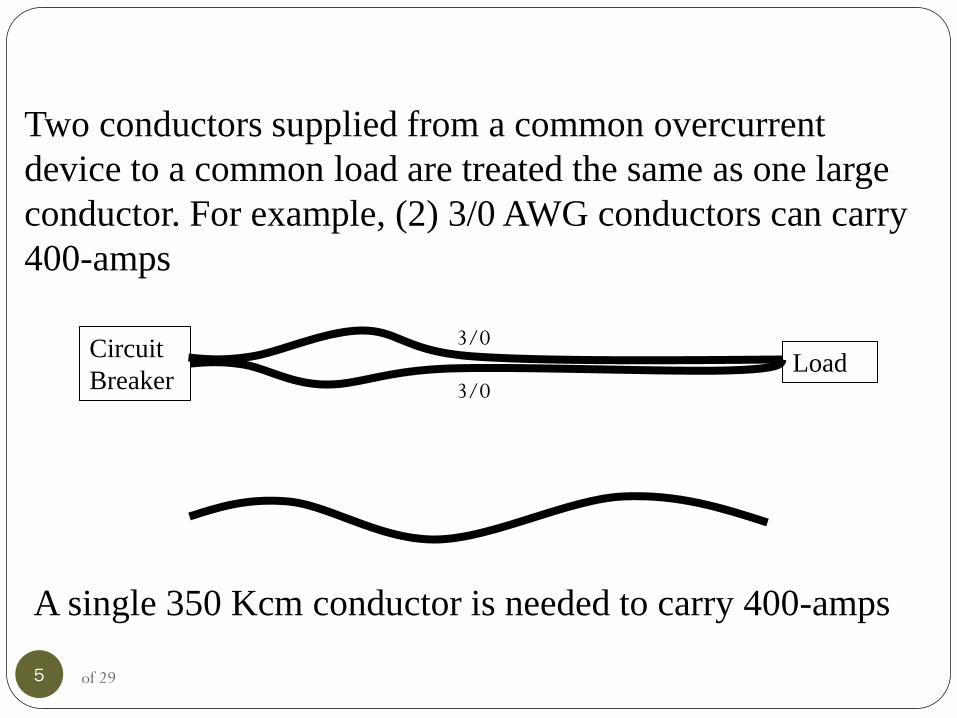
Two conductors supplied from a common overcurrent
device to a common load are treated the same as one large
conductor. For example, (2) 3/0 AWG conductors can carry
400-amps
3/0
3/0
A single 350 Kcm conductor is needed to carry 400-amps
of 29

6
A 3/0 AWG conductor has
167,800 circular mils, 2 of
the conductors = 335,600
circular mils. These two
conductors in parallel can
carry 400-amps. A single
350 Kcm conductor can
carry 400-amps but is
350,000 circular mils in
size.
of 29

Parallel Conductors
On most installations, paralleled conductors are
generally not used until 400-amp or larger services
are installed. Section 310.10(H) governs the use of
parallel conductors. Generally, the conductors are
sized at a minimum of 1/0 AWG before they are
allowed to be used in parallel. A 400-amp panel will
generally have (2) 4/0 aluminum or (2) 3/0 copper
conductors per phase.
7 of 29

Conductors run in parallel are required to be the
same size, length, insulation, material and
terminated in the same manner, 310.10(H)(2). If the
parallel conductors are in the same raceway, conduit
fill and de-rate for current-carrying conductors can
apply. Separate raceways require each raceway to
have a full size EGC installed in each raceway. The
following slides show common installations, some
with code violations.
The principal for parallel runs is the same for single-
phase or three-phase loads. 8 of 29
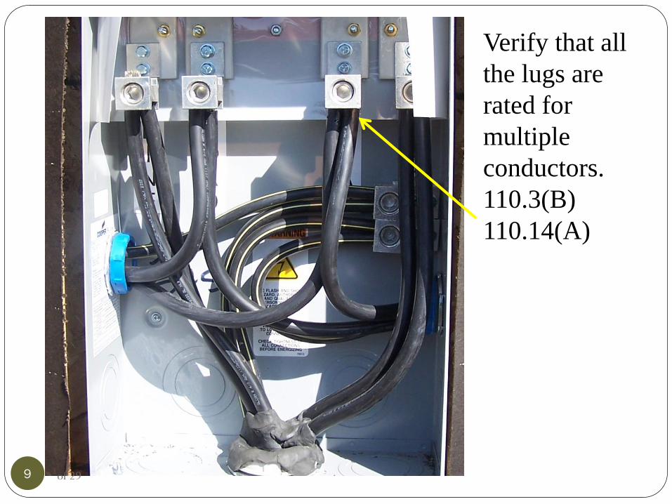
Verify that all
the lugs are
rated for
multiple
conductors.
110.3(B)
110.14(A)
9 of 29

This slide shows a violation of 310.10(H)(3). Each
conduit should have the same number of conductors
and a full size EGC
6 conductors
80% de-rate 3 3 3
10 of 29
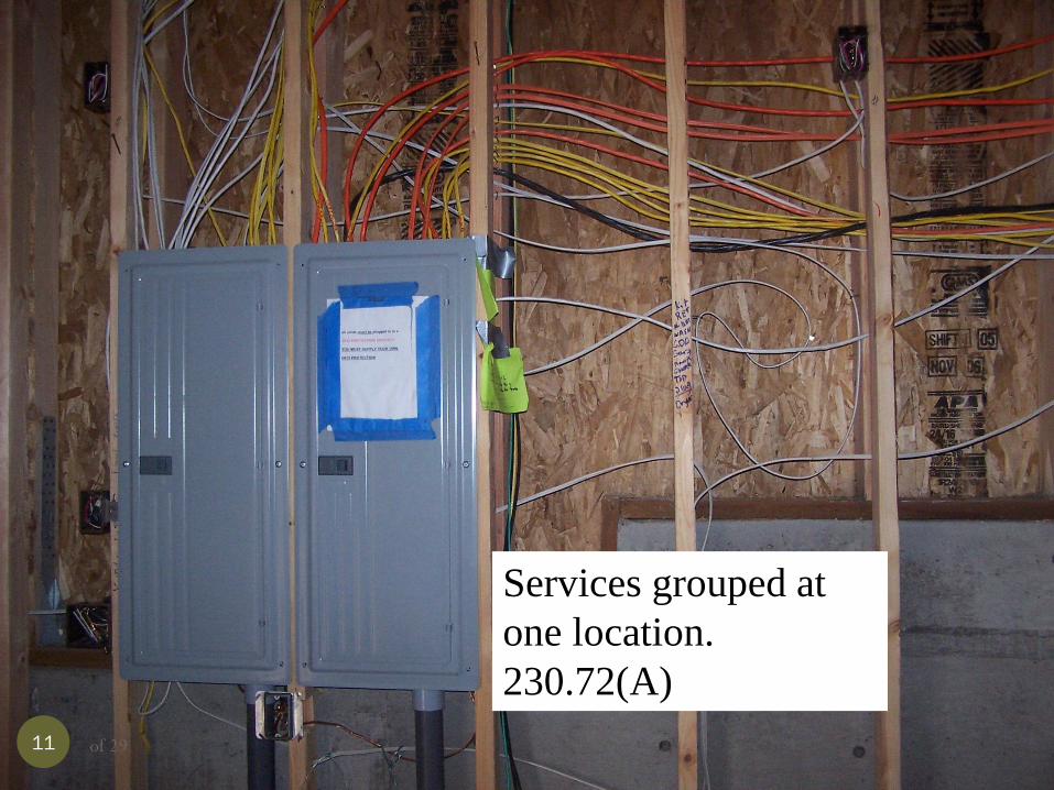
Services grouped at
one location.
230.72(A)
11 of 29
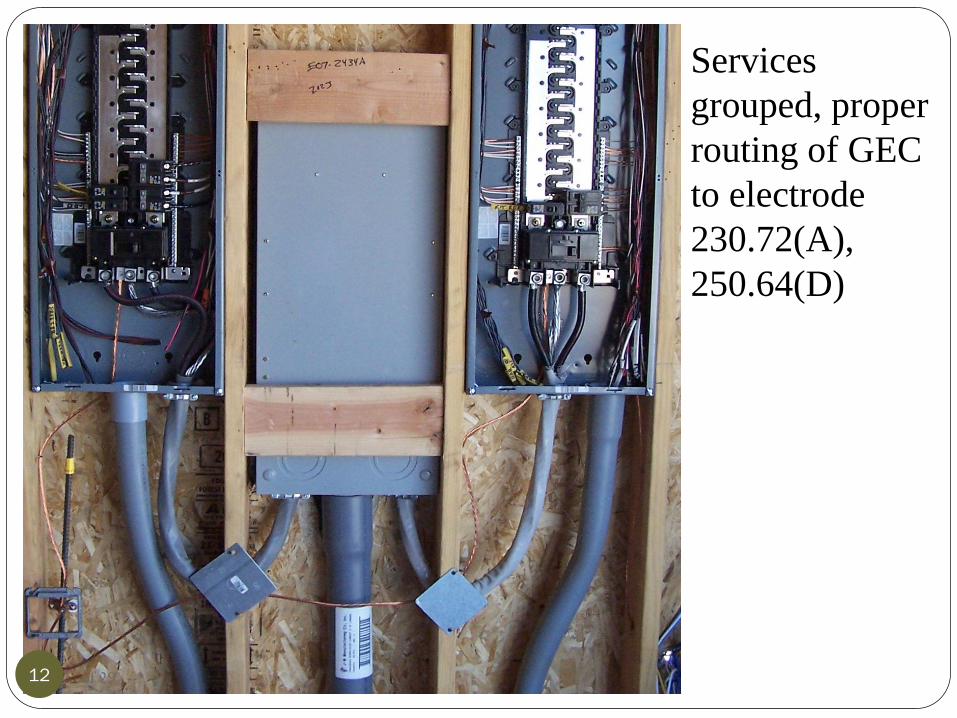
Services
grouped, proper
routing of GEC
to electrode
230.72(A),
250.64(D)
12 of 29

Proper routing
of GEC and
taps per
250.64(D)
13 of 29

Lugs are rated for
only one
conductor, main
bonding jumper
not installed
correctly.
250.28, 110.3(B)
200.2(B)
14 of 29
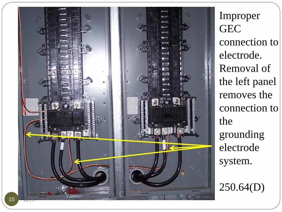
Improper
GEC
connection to
electrode.
Removal of
the left panel
removes the
connection to
the
grounding
electrode
system.
250.64(D) 15 of 29
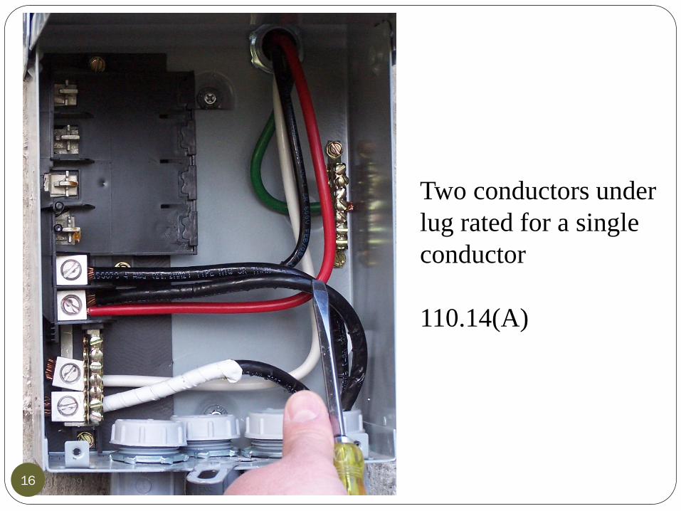
Two conductors under
lug rated for a single
conductor
110.14(A)
16 of 29

310.10(H) Conductors in Parallel.
(1) General. Aluminum, copper-clad aluminum, or
copper conductors, for each phase, polarity, neutral,
or grounded circuit shall be permitted to be connected
in parallel (electrically joined at both ends) only in
sizes 1/0 AWG and larger where
installed in accordance with 310.10(H)(2) through
(H)(6).
17 of 29

310.10(H)(2) Conductor and installation
Characteristics.
The paralleled conductors in each phase, polarity,
neutral, grounded circuit conductor, equipment
grounding conductor, or equipment bonding
jumper shall comply with all of the following:
(1) Be the same length
(2) Consist of the same conductor material
(3) Be the same size in circular mil area
(4) Have the same insulation type
(5) Be terminated in the same manner
18 of 29

310.10(H)(3) Separate Cables or Raceways.
Where run in separate cables or raceways, the cables
or raceways with conductors shall have the same
number of conductors and shall have the
same electrical characteristics. Conductors of one
phase, polarity, neutral, grounded circuit conductor,
or equipment grounding conductor shall not be
required to have the same physical characteristics as
those of another phase, polarity, neutral, grounded
circuit conductor, or equipment grounding
conductor.
19 of 29

(4) Ampacity Adjustment. Conductors installed in
parallel shall comply with the provisions of
310.15(B)(3)(a).
(5) Equipment Bonding Conductors. Where
parallel equipment bonding conductors are used, they
shall be sized in accordance with 250.122.
(6) Bonding Jumpers. Where parallel equipment or
supply-side bonding jumpers are installed in
raceways, they shall be sized and installed in
accordance with 250.102.
20 of 29

21 of 29

22 of 29

250.122(F) Conductors in Parallel. Where
conductors are installed in parallel in multiple
raceways or cables as permitted in 310.10(H), the
equipment grounding conductors, where used, shall
be installed in parallel in each raceway or cable.
Where conductors are installed in parallel in the same
raceway, cable, or cable tray as permitted in
310.10(H), a single equipment grounding conductor
shall be permitted.
Each equipment grounding conductor shall be sized
in compliance with 250.122.
23 of 29

Incorrect marking
of conductors on
transfer switch
for generator.
Only grounded
(neutral)
conductors can
be marked white.
200.7
24 of 29

25
200.7 Use of Insulation of a White or Gray Color
or with Three Continuous White or Gray Stripes
(A) General. The following shall be used only for
the grounded circuit conductor, unless otherwise
permitted in 200.7(B) and (C):
(1)A conductor with continuous white or gray
covering
(2)A conductor with three continuous white or gray
stripes on other than green insulation
(3) A marking of white or gray color at the
termination
of 29
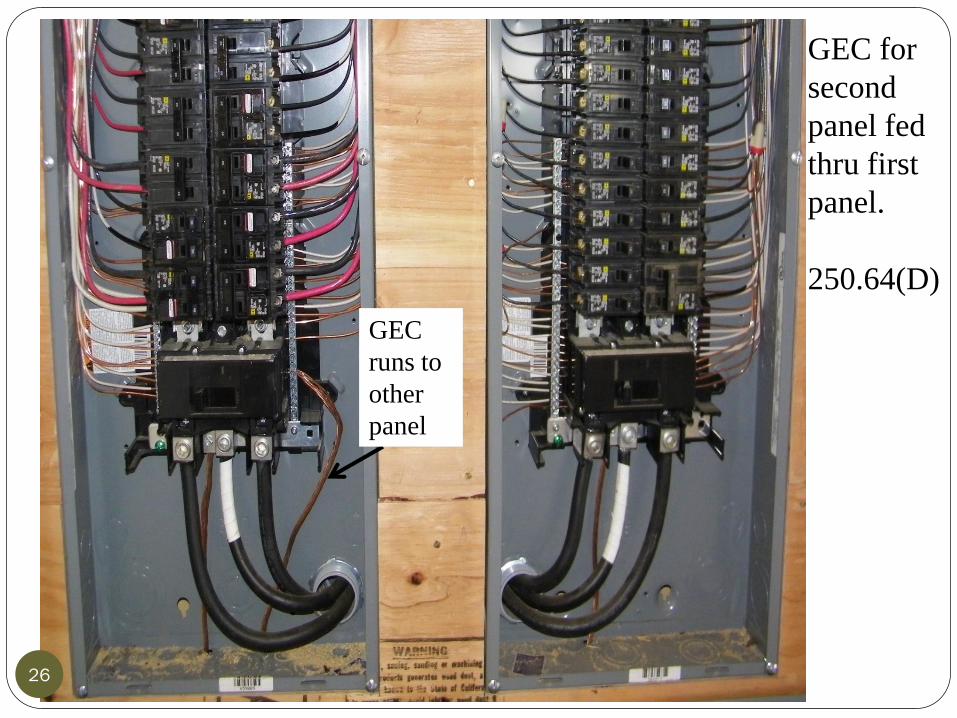
GEC for
second
panel fed
thru first
panel.
250.64(D)
GEC
runs to
other
panel
26 of 29

27
(D) Building or Structure with Multiple
Disconnecting Means in Separate Enclosures.
For a service or feeder with two or more
disconnecting means in separate enclosures
supplying a building or structure, the grounding
electrode connections shall be made in
accordance with 250.64(D)(1), (D)(2), or (D)(3).
of 29

28 of 29

29
Lesson 9 and Lesson 10 Questions
will be sent to you
of 29