residential code of ohiocom.ohio.gov/documents/dico_2013rcochapter3handouts.pdf · residential code...
TRANSCRIPT

Residential Code of Ohio Residential Code of Ohio
Chapter 3 RequirementsChapter 3 Requirements
Building PlanningBuilding Planning
Ohio Board of Building Standards
Figures 302.1(1), 302.1(2), 302.1(3), 302.2.2(1), 302.2.2(2), 314.3(2), 315.1
Excerpted from the 2009 International Residential Code Commentary,
Copyright 2010
Page 75
Excerpted from the 2009 IRC Significant Changes, Copyright 2009
Reproduced with permission. All rights reserved. www.ICCSAFE.org
For dwelling units:For dwelling units:–– Structural Integrity Structural Integrity ––
•• LoadsLoads–– Dead loads, Live loads, Flood, Snow, Wind and Seismic loadsDead loads, Live loads, Flood, Snow, Wind and Seismic loads
•• Decay & Insect protectionDecay & Insect protection•• Flood resistance, storm shelters; post frame structuresFlood resistance, storm shelters; post frame structures
–– Fire SafetyFire Safety•• Fire Resistance of components, openings & materialsFire Resistance of components, openings & materials
–– Within a dwelling, Between dwellings, Within a dwelling, Between dwellings, FireblockingFireblocking & & draftstoppingdraftstopping, , Foam plasticsFoam plastics
–– Life SafetyLife Safety•• Egress Egress
–– Doors, Emergency escape & rescue, Stairs, Handrails, Guards (falDoors, Emergency escape & rescue, Stairs, Handrails, Guards (fall l protection)protection)
•• Protection systemsProtection systems–– Fire sprinklers, Smoke alarms, Carbon Monoxide alarms; GlazingFire sprinklers, Smoke alarms, Carbon Monoxide alarms; Glazing
•• Site addressSite address
–– Livability Livability ––•• light; ventilation; heating; sanitation; minimum room size/ceililight; ventilation; heating; sanitation; minimum room size/ceiling ng height; bathroom spaces; environmental comfort; usability (incluheight; bathroom spaces; environmental comfort; usability (including ding elevators); Garage & carportselevators); Garage & carports
Chapter 3 in the 2013 RCOChapter 3 in the 2013 RCO

301.1 Application301.1 Application
Requires all buildings to safely support/resist all Requires all buildings to safely support/resist all imposed loadsimposed loads…….building load transfer & load .building load transfer & load resisting systems must transfer loads through the resisting systems must transfer loads through the foundation system to soil.foundation system to soil.
–– Design/Construction must provide a complete load Design/Construction must provide a complete load path from point of origin through the loadpath from point of origin through the load‐‐resisting resisting elements to the foundation.elements to the foundation.
–– Prescribes actual construction details and Prescribes actual construction details and requirementsrequirements
301.1.1 Alternative Provisions301.1.1 Alternative Provisions
•• The alternative prescriptive framing methods of the The alternative prescriptive framing methods of the following standards may be used for design and following standards may be used for design and construction when design complies with the OBC:construction when design complies with the OBC:
–– WFCM WFCM ‐‐ Wood Frame Construction Manual by AF&PAWood Frame Construction Manual by AF&PA
–– AISI S230 AISI S230 ‐‐ Standard for ColdStandard for Cold‐‐Formed Steel Framing Formed Steel Framing ––Prescriptive Method for 1Prescriptive Method for 1‐‐ and 2and 2‐‐Family Dwellings Family Dwellings
–– ICCICC‐‐400 (2007) 400 (2007) ‐‐ Standard on the Design and Construction Standard on the Design and Construction of Log Structuresof Log Structures

301.1.2 Construction Systems301.1.2 Construction Systems
•• The requirements of this code are based on:The requirements of this code are based on:
–– Platform and balloonPlatform and balloon‐‐frame construction for lightframe construction for light‐‐frame frame buildingsbuildings
–– BalloonBalloon‐‐frame systems for concrete and masonry buildings frame systems for concrete and masonry buildings and lightand light‐‐frame buildings.frame buildings.
•• Other systems may be used if equivalent details are Other systems may be used if equivalent details are provided to ensure force transfer, continuity & provided to ensure force transfer, continuity & deformation compatibilitydeformation compatibility
Construction SystemsConstruction Systems
•• Are dwellings that are constructed using postAre dwellings that are constructed using post‐‐frame methods equivalent to the platform and frame methods equivalent to the platform and balloonballoon‐‐frame construction methods of the frame construction methods of the RCO?RCO?
•• What standard is used to design and determine What standard is used to design and determine compliance?compliance?
301.1.3 Engineered Design301.1.3 Engineered Design
•• When a building or conventional system When a building or conventional system containing structural elements not in containing structural elements not in compliance with the code, then the elements compliance with the code, then the elements must be designed per accepted engineering must be designed per accepted engineering practicepractice
–– Only applies to the nonconforming portion of the Only applies to the nonconforming portion of the systemsystem

Engineered DesignEngineered Design
•• What constitutes What constitutes ““accepted engineering accepted engineering practicepractice””??
–– Not defined in the RCONot defined in the RCO
–– Generally means that the analysis is based on Generally means that the analysis is based on accepted principles and standards which is accepted principles and standards which is nationally recognizednationally recognized
–– The Building Official must determine if the The Building Official must determine if the analysis is in accordance with analysis is in accordance with ““accepted accepted engineering practiceengineering practice””
301.2 Climatic and Geographic Design 301.2 Climatic and Geographic Design CriteriaCriteria
•• Buildings are to be constructed per Buildings are to be constructed per requirements in this section, PLUSrequirements in this section, PLUS
•• Per additional criteria in Table 301.2(1)Per additional criteria in Table 301.2(1)
Table 301.2(1) Climatic and Geographic Table 301.2(1) Climatic and Geographic Design CriteriaDesign Criteria

Table 301.2(1), continuedTable 301.2(1), continued……
Table 301.2(1) Climatic and Table 301.2(1) Climatic and Geographic Design CriteriaGeographic Design Criteria
–– Ground Snow Load Ground Snow Load –– 20 20 psfpsf for for western Ohio;western Ohio;
25 25 psfpsf for parts of eastern and for parts of eastern and central Ohio; an area east of central Ohio; an area east of Cleveland requires consultation with Cleveland requires consultation with the local building department for site the local building department for site specific snow loads (Figure specific snow loads (Figure R301.2(5))R301.2(5))
Contrasts with OBC 1608 which allows Contrasts with OBC 1608 which allows local ordinance to specify snow load local ordinance to specify snow load based on historical databased on historical data
•• Wind Speed Wind Speed –– All of Ohio is subject to 3All of Ohio is subject to 3‐‐second gust second gust of 90 mphof 90 mph
–– Must use Section 301.2.1.4 for Exposure Category (varies Must use Section 301.2.1.4 for Exposure Category (varies from site to site)from site to site)
•• Topographic Effects Topographic Effects ‐‐ Has been deleted from Has been deleted from RCORCO……must use Exposure Categoriesmust use Exposure Categories
Table 301.2(1) Climatic and Table 301.2(1) Climatic and Geographic Design CriteriaGeographic Design Criteria

•• Seismic Design Category Seismic Design Category –– All of Ohio is located with All of Ohio is located with SDC A or B.SDC A or B.
–– The building designer may choose (but not required) to The building designer may choose (but not required) to design to a stricter SDC Categorydesign to a stricter SDC Category
•• Structure must be built per approved construction documents.Structure must be built per approved construction documents.
Table 301.2(1) Climatic and Table 301.2(1) Climatic and Geographic Design CriteriaGeographic Design Criteria
•• Subject to Damage from:Subject to Damage from:
–– Weathering Weathering –– All of Ohio is SevereAll of Ohio is Severe
–– Frost Line Depth Frost Line Depth –– Varies from 30Varies from 30”” to 48to 48”” and must be and must be specified by each local jurisdiction via ordinance based on specified by each local jurisdiction via ordinance based on evidence evidence
–– Termite Termite –– All of Ohio is Moderate to SevereAll of Ohio is Moderate to Severe
Table 301.2(1) Climatic and Table 301.2(1) Climatic and Geographic Design CriteriaGeographic Design Criteria
•• Winter Design TemperatureWinter Design Temperature
Table 301.2(1) Climatic and Table 301.2(1) Climatic and Geographic Design CriteriaGeographic Design Criteria

•• Ice Barrier UnderlaymentIce Barrier Underlayment
–– Is required in all of OhioIs required in all of Ohio
–– Requirements described in Section 905.2.7.1Requirements described in Section 905.2.7.1
•• Flood HazardsFlood Hazards
–– Local jurisdiction must enter appropriate dates and panel Local jurisdiction must enter appropriate dates and panel numbersnumbers
Table 301.2(1) Climatic and Table 301.2(1) Climatic and Geographic Design CriteriaGeographic Design Criteria
Table 301.2(1) Climatic and Table 301.2(1) Climatic and Geographic Design CriteriaGeographic Design Criteria
–– Flood Hazards Flood Hazards –– Date of the FEMA FIRM map for the Date of the FEMA FIRM map for the jurisdiction, if applicablejurisdiction, if applicable
–– Air Freezing Index Air Freezing Index –– Ranges from 1000 in southern & Ranges from 1000 in southern & eastern Ohio to 1500 in northwest Ohio (cumulative eastern Ohio to 1500 in northwest Ohio (cumulative degree days below 32degree days below 32ººF F –– Figure R403.3(2) or Table Figure R403.3(2) or Table 403.3(2))403.3(2))
–– Mean Annual Temp. Mean Annual Temp. ‐‐ Ranges from 50Ranges from 50ººF to 52F to 52ººF from F from North to South (from the National Climate Data Center North to South (from the National Climate Data Center www.ncdc.noaa.gov/fpsf.htmlwww.ncdc.noaa.gov/fpsf.html))
Structural DesignStructural Design
–– 301.2.1 Wind Limitations 301.2.1 Wind Limitations
–– 301.2.2 Seismic Provisions 301.2.2 Seismic Provisions
–– 301.2.3 Snow Loads301.2.3 Snow Loads
–– 301.2.4 Floodplain Construction301.2.4 Floodplain Construction
301.2.1.4 Exposure Category301.2.1.4 Exposure Category•• Exposure A: Exposure A: Large city centersLarge city centers•• Exposure BExposure B: Urban and suburban areas, wood areas or other : Urban and suburban areas, wood areas or other
terrain with many closely spaced obstructions having the size ofterrain with many closely spaced obstructions having the size ofsinglesingle‐‐family dwellings or larger. family dwellings or larger. This exposure shall be assumed in This exposure shall be assumed in the design unless the site meets the definition of another exposthe design unless the site meets the definition of another exposure ure type.type.
•• Exposure CExposure C: Open with scattered obstructions or undulations : Open with scattered obstructions or undulations generally less than 30 ft. in height extending for 1,500 ft. in generally less than 30 ft. in height extending for 1,500 ft. in any any direction.direction.–– Within Exposure B terrain, but located directly adjacent to openWithin Exposure B terrain, but located directly adjacent to open areas areas
of Exposure C for a distance of more than 600 ft.of Exposure C for a distance of more than 600 ft.
•• Exposure D: Exposure D: Flat, unobstructed areas exposed to wind flowing over Flat, unobstructed areas exposed to wind flowing over open water for at least 1 mile. open water for at least 1 mile.
301.2.1.5 Topographic Wind Effects301.2.1.5 Topographic Wind Effects
•• This section and its subsection 301.2.1.5.1 This section and its subsection 301.2.1.5.1 (Simplified topographic wind speed method) (Simplified topographic wind speed method) are deleted.are deleted.

301.2.2 Seismic Provisions301.2.2 Seismic Provisions
•• Ohio is established as SDC A or BOhio is established as SDC A or B
•• Seismic provisions for SDC C or greater do not Seismic provisions for SDC C or greater do not applyapply
–– If a building is designed to SDC C or greater, and If a building is designed to SDC C or greater, and the construction documents are approved, the construction documents are approved, installation in the field must follow the approved installation in the field must follow the approved construction documentsconstruction documents
301.2.3 Snow Loads301.2.3 Snow Loads
•• The provisions of the RCO is limited to ground The provisions of the RCO is limited to ground snow loads up to 70 snow loads up to 70 psfpsf
•• Structures subject to ground snow loads Structures subject to ground snow loads exceeding 70 exceeding 70 psfpsf must be designed in must be designed in accordance with accepted engineering accordance with accepted engineering practicepractice
301.2.4 Floodplain Construction301.2.4 Floodplain Construction
•• Any portion of a building or structure Any portion of a building or structure constructed in flood hazard areas (including A constructed in flood hazard areas (including A or V Zones) must be designed and constructed or V Zones) must be designed and constructed per Section 322.per Section 322.
–– Any portion of a building or structure located Any portion of a building or structure located within identified floodways must be designed and within identified floodways must be designed and constructed per ASCE 24.constructed per ASCE 24.

301.3 Story Height301.3 Story Height
–– Section 301.3 defines story height and wall height Section 301.3 defines story height and wall height limits.limits.•• Wood Wall Framing: See Table 602.3(5) for allowable laterally Wood Wall Framing: See Table 602.3(5) for allowable laterally unsupported bearing wall stud heights (Stud height of 10 unsupported bearing wall stud heights (Stud height of 10 feet, plus max. 16feet, plus max. 16”” floor framing height)floor framing height)
–– Exception: Can be 12 feet for bracing provided appropriate Exception: Can be 12 feet for bracing provided appropriate multiplying factors are provided to the required bracing.multiplying factors are provided to the required bracing.
•• Steel Wall Framing: Stud height of 10 feet, plus max. 16Steel Wall Framing: Stud height of 10 feet, plus max. 16”” floor floor framing heightframing height
•• Masonry Wall: Max clear height of 12 feet, plus max. 16Masonry Wall: Max clear height of 12 feet, plus max. 16””floor framing heightfloor framing height
–– Additional 8 feet permitted for gable end wallAdditional 8 feet permitted for gable end wall
301.3 Story Height301.3 Story Height–– Individual walls or studs can exceed these limits as Individual walls or studs can exceed these limits as permitted in Chapter 6, provided the story heights are permitted in Chapter 6, provided the story heights are not exceeded.not exceeded.
–– Floor framing height can exceed 16Floor framing height can exceed 16”” provided the provided the story height does not exceed 11story height does not exceed 11’’‐‐77””..
–– Engineered Design must be provided if wall framing Engineered Design must be provided if wall framing members exceed the limits of Chapter 6.members exceed the limits of Chapter 6.
–– Engineered Design in accordance with the OBC must Engineered Design in accordance with the OBC must be provided if the story height limits are exceeded.be provided if the story height limits are exceeded.
Design LoadsDesign Loads
–– 301.4 Dead Load301.4 Dead Load
–– 301.5 Live Load301.5 Live Load
–– 301.6 Roof Load301.6 Roof Load
–– 301.7 Deflection301.7 Deflection
–– 301.8 Nominal Sizes301.8 Nominal Sizes

301.4 Dead Load301.4 Dead Load
–– Dead load is the Dead load is the actual weights of actual weights of materials and materials and construction and construction and load of fixed service load of fixed service equipmentequipment
301.5 Live Load301.5 Live Load
• Balconies = 40psf• Habitable attics and attics served with
fixed stairs = 30psf
301.6 Roof Loads301.6 Roof Loads–– 301.6 Roof Load 301.6 Roof Load –– Roof shall be designed per Roof shall be designed per
Table 301.6 OR the snow load per Table R301.2(1) Table 301.6 OR the snow load per Table R301.2(1) WHICHEVER IS GREATER.WHICHEVER IS GREATER.
–– All of Ohio is or exceeds 20 All of Ohio is or exceeds 20 psfpsf snow load; therefore, Table snow load; therefore, Table R301.6 does not apply in Ohio.R301.6 does not apply in Ohio.

301.7 Allowable Deflections301.7 Allowable Deflections
SECTION 302SECTION 302FIREFIRE‐‐RESISTANT CONSTRUCTIONRESISTANT CONSTRUCTION
302.1 Exterior Walls302.1 Exterior WallsConstruction, projections, openings of dwellings and Construction, projections, openings of dwellings and accessory buildings shall comply with table:accessory buildings shall comply with table:

302.1 Exterior Walls302.1 Exterior Walls
WhereWhere referenced in this code, an occupied referenced in this code, an occupied space on an adjoining property may be space on an adjoining property may be included in the required fire separation included in the required fire separation distance, provided that the property is distance, provided that the property is dedicated or deeded so as to preclude, for dedicated or deeded so as to preclude, for the life of the structure, the erection of the life of the structure, the erection of another building or structure.another building or structure.
Exceptions to Table 302.1Exceptions to Table 302.1
•• 302.1 Exterior Walls302.1 Exterior Walls
–– ExceptionsExceptions
1.1. Construction, projections, openingsConstruction, projections, openings perpendicular to the line used to perpendicular to the line used to determine the fire separation distance.determine the fire separation distance.
2.2. Walls of dwellings and accessory structures located on the same Walls of dwellings and accessory structures located on the same lot.lot.
3.3. Walls of structures exempted from approval per Section 102.10, Walls of structures exempted from approval per Section 102.10, except that projects beyond the exterior wall must not extend ovexcept that projects beyond the exterior wall must not extend over er the lot line.the lot line.
4.4. Detached garages located within 2Detached garages located within 2’’ of a lot line may have a roof eave of a lot line may have a roof eave projection not exceeding 4projection not exceeding 4””
5.5. Foundation vents in compliance with this code are permitted.Foundation vents in compliance with this code are permitted.

Location on the Lot Location on the Lot 302.1 Exterior Walls302.1 Exterior Walls
Required to be Required to be 11‐‐hour if the hour if the wall is located wall is located within 3 feet of within 3 feet of property lineproperty line
Exception: Exception: Garages Garages which are which are 22’’ from from the line the line can have a can have a max. 4max. 4””projection projection Underside Underside of of projectionprojections must also s must also be 1be 1‐‐hour hour and and cannot becannot be
•• 310.1 of OBC, R310.1 of OBC, R‐‐3 occupancy designs 3 occupancy designs qualifying for use of RCO:qualifying for use of RCO:
–– Independent means of egress for each Independent means of egress for each unitunit
–– No more than one unit over anotherNo more than one unit over another
–– Fire separation in accordance with this Fire separation in accordance with this sectionsection
–– Administered through OBC Chapter 1Administered through OBC Chapter 1
302.2 Multiple Dwelling Separation (>2)302.2 Multiple Dwelling Separation (>2)

Dwelling Unit SeparationsDwelling Unit Separations
When using the RCO for RWhen using the RCO for R‐‐3 designs, the following 3 designs, the following apply:apply:
1.1. Fire separation between a group of two units Fire separation between a group of two units must comply with 302.3 (1 hr.)must comply with 302.3 (1 hr.)
2.2. Fire separation between a two unit group and Fire separation between a two unit group and other dwelling units must comply with 302.2 (2 other dwelling units must comply with 302.2 (2 hr. or two 1 hr.)hr. or two 1 hr.)
302.2 and 302.3 Dwelling Separation302.2 and 302.3 Dwelling Separation
OR
Common two-hour wall may not have any
plumbing or mechanical equipment,
ducts or vents in the cavity and must be
rated for fire exposure from both sides
All separating assemblies must be tested in accordance with ASTM E119 or
UL 263
Rating must extend from
foundation to the underside of roof
sheathing, deck or slab
Dwelling SeparationDwelling Separation
All separating assemblies must be tested in accordance with ASTM E119 or
UL 263
Construction supporting rated
assemblies must have equal or greater fire-
resistive ratings. One hr rated assembly

Dwelling Unit SeparationsDwelling Unit SeparationsRR‐‐3 Separations3 Separations
Two 1 hr. walls or one 2 hr. wall
Dwelling unit
Dwelling unit
Dwelling unit
1 hr. separation Dwelling
unit
Grade level access for upper units
Grade level access for lower units
R-3: CAN USE RCO
Dwelling Unit SeparationsDwelling Unit SeparationsRR‐‐3 Separations3 Separations
Dwelling unit
Dwelling unit
Dwelling unit
Dwelling unit
Grade level access for all
upper units
Grade level access for lower units
R-3: BUT CANNOT USE RCO
Dwelling unit
Separation DetailsSeparation Details302.2.2 Parapets302.2.2 Parapets
–– Required for townhousesRequired for townhouses
–– Must be the same rating as Must be the same rating as the separation wallthe separation wall
–– Must extend 30Must extend 30”” above the above the lowest roof on either sidelowest roof on either side
–– Where roof elevations are Where roof elevations are offset by at least 30offset by at least 30””, the fire , the fire rating of the separation from rating of the separation from the top of the lower roof to the top of the lower roof to the bottom of the lower roof the bottom of the lower roof may be 1 hr. rated.may be 1 hr. rated.

Separation DetailsSeparation Details302.2.2 Parapets302.2.2 Parapets
Exception: Parapets need not extend above the roof if:Exception: Parapets need not extend above the roof if:
–– The roof covering is Class C minimumThe roof covering is Class C minimum
–– The decking is nonThe decking is non‐‐combustible or FRTW for a distance of 4combustible or FRTW for a distance of 4’’ from the from the wall on each side or 5/8wall on each side or 5/8”” type X gypsum is attached to the bottom of type X gypsum is attached to the bottom of the deck for a distance of 4the deck for a distance of 4’’ on each side.on each side.
Separation DetailsSeparation Details
302.2.3 Parapet Construction (see Fig. 302.2.2(1))302.2.3 Parapet Construction (see Fig. 302.2.2(1))
•• Must have the same fire resistance rating as that required forMust have the same fire resistance rating as that required forthe supporting wall or walls.the supporting wall or walls.
•• On any side adjacent to a roof surface, the parapet must have On any side adjacent to a roof surface, the parapet must have noncombustible facing for the uppermost 18 inches including noncombustible facing for the uppermost 18 inches including countercounter‐‐flashing and coping materials).flashing and coping materials).
•• Where the roof slopes toward a parapet at slopes > 2:12Where the roof slopes toward a parapet at slopes > 2:12
•• Parapet must extend to the same height as any portion of the rooParapet must extend to the same height as any portion of the roof f within a distance of 3 feetwithin a distance of 3 feet
•• In no case shall the height be less than 30 inches.In no case shall the height be less than 30 inches.
Separation DetailsSeparation Details
302.2.4 Structural independence302.2.4 Structural independence
•• Each individual dwelling unit must be structurally Each individual dwelling unit must be structurally independentindependent
Exceptions:Exceptions:1.1. Foundations supporting exterior walls or common wallsFoundations supporting exterior walls or common walls
2.2. Structural roof and wall sheathing from each unit may fasten to Structural roof and wall sheathing from each unit may fasten to the the common wall framingcommon wall framing
3.3. Nonstructural wall and roof coveringsNonstructural wall and roof coverings
4.4. Flashing at termination of roof covering over common wall.Flashing at termination of roof covering over common wall.
5.5. Dwelling units separated by a common 2Dwelling units separated by a common 2‐‐hour firehour fire‐‐resistance rated resistance rated was per Section 302.2was per Section 302.2
6.6. Dwelling units stacked vertically.Dwelling units stacked vertically.

Rated Penetrations 302.4
• Assemblies required to be rated by sections 302.2 or 302.3 must be protected in accordance with 302.4.1 & 302.4.2 (see fig. 302.4.1)
– Through penetrations
– Fire resistance rated assemblies
– Penetration firestop systems …
– Membrane penetrations
Garage/Dwelling Assemblies 302.5• Openings
– None allowed between garage and sleeping areas– Openings to other rooms limited to:
• Solid wood doors• Steel doors• 20 minute rated doors
• Ducts and Other Penetrations– Ducts min. 26 ga. with no garage openings– 302.5.3 misprint …309.2 should be 302.6 penetrations protected in accordance with 302.11(4)
• Separation – In accordance with Table 302.6 (see Fig 302.5.2)
Fire & Smoke Risk General Provisions• Under‐stairs 302.7
– Enclosed areas surfaces minimum ½ Gypsum
• Foam Plastics 316• Flame spread index & Smoke‐developed index
– Walls, ceiling, trim 302.9– Insulation 302.10– Limits, testing….validation
• Fireblocking– Required in wood frame (see figs 302.11(1‐11))
• Concealed stud & furred spaces, soffits, dropped ceilings, spaces around bathtubs, top & bottom of stair runs, pipes, ducts, chimneys, etc.
• Materials 302.11.1, 7 options • Insulation
– Batts for horizontal req– Using Unfaced – 16” hgt., tightly packed around pipes, etc.– Loose fill use– maintained
• Draftstopping 302.12 – combustible construction– When concealed area exceeds 1000 sq ft with usable space above or below,
draftstopping (1/2” gyp, 3/8 plywood) dividing spqce in half is required
• Combustible insulation clearance of 3” required adjacent to heat producing devices – 302.13

Fire Resistance Determination
• 302.14 Fire resistance can be verified for compliance by:– test results of materials, components or assemblies to ASTM 119 or UL 263
– OBC Section 721 – Calculated fire resistance
– ICC International Existing Buildings Code, Resource A, Guidelines on Fire Ratings of Archaic Materials and Assemblies
• Equivalent fire resistive values can be derived for components not required to be rated by using OBC section 721 and Resource A
SECTION 303 SECTION 303
Light, Ventilation & HeatingLight, Ventilation & Heating
SECTION 304 SECTION 304
Minimum Room sizesMinimum Room sizes

SECTION 305 SECTION 305
Ceiling HeightCeiling Height
SECTION 306 SECTION 306
SanitationSanitation
SECTION 307
Toilet Bath & Shower Spaces

SECTION 308 SECTION 308 GlazingGlazing
308.1 Identification
• Each pane of glazing installed in hazardous locations must be provided with a manufacturer’s designation specifying:– Who applied the designation– Type of glass – Safety glazing standard with which it complies
• Identification must be visible at time of final inspection• Must be etched, sandblasted, embossed, or of a type that cannot be
removed without being destroyed.• A label is permitted in lieu of the manufacturer’s designation.
Picture courtesy of ©Code Check.Safety Glazing Article found in October 2011 Edition of ASHI Reporter Magazine
308.1 Identification, continued…
• Exceptions:1. Non‐Tempered Glass: Building official may approve the use of
a certificate, affidavit or other evidence confirming compliance with this code for glass without the manufacturer’s designation.
2. Tempered Glass: Permitted to be identified by the manufacturer with a removable paper designation only when it is spandrel glass.
• 308.1.1 Identification of Multiple Assemblies– Only one pane is required to be identified when all of the
individual panes do not exceed 1 sq.ft. in exposed area.– Must be identified per 308.1– All other pane in the assembly must be labeled “CPSC 16 CFR
1201” or “ANSI Z97.1” as appropriate.

308.2 Louvered Windows or Jalousies
• Regular, float, wired or patterned glass in jalousies and louvered windows must be no thinner than nominal 3/16 inch and no longer than 48 inches.
• Exposed glass edges must be smooth.
– 308.2.1 Wire Glass Prohibited
• Wired glass with wire exposed on longitudinal edges shall not be used in jalousies or louvered windows.
308.3 Human Impact Loads
• Individual glazed areas, including glass mirrors in areas identified as hazardous, must meet the testing requirements of Section 308.3.1
– Exceptions:
1. Louvered windows and jalousies complying with Section 308.2.
2. Mirrors and other glass panels mounted or hung on a surface that provides a continuous backing support.
3. Glass unit masonry complying with Section 610.
308.3.1 Impact Test
• Glazing in doors or enclosures for hot tubs, whirlpools, saunas, steam rooms, bathtubs and showers must be tested per CPSC 16 CFR 1201 and comply with test criteria for Category I or II as indicated in Table 308.3.1(1)

308.3.1 Impact Test
• Glazing in any other location are permitted to be tested per ANSI Z97.1 and comply with the text criteria for Class A or B as indicated in Table 308.3.1(2).
308.4 Hazardous Locations
• The following is considered specific hazardous locations for the purposes of glazing:
1. Glazing in all fixed and operable panels of swinging, sliding and bifold doors
– Exceptions:
• Glazed openings of a size through which a 3 inch diameter sphere is unable to pass.
• Decorative glazing
308.4 Hazardous Locations
• The following is considered specific hazardous locations for thepurposes of glazing:2. Glazing in an individual fixed or operable panel adjacent to a door
where:• The nearest vertical edge is within a 24‐inch arc of the door in a closed
position;• The bottom edge of glazing with <60 inches above the floor/walking surface
– Exceptions:1. Decorative glazing2. When there is an intervening wall or other permanent barrier between the
door and the glazing3. Glazing in walls on the latch side of and perpendicular to the plane of the door
in a closed position4. Glazing adjacent to a door where the access through the door is to a closet or
storage area 3 feet or less in depth5. Glazing adjacent to the fixed panel of patio doors.

See Exception No. 5
See Exception No. 2

How much of a wall or barrier is needed to qualify for Exception 2?
308.4 Hazardous Locations
• The following is considered specific hazardous locations for the purposes of glazing:3. Glazing in an individual fixed or
operable panel that meets all of the following conditions:1. The exposed area of an individual
pane exceeds 9 sq.ft.; and,2. The bottom edge of glazing is less
than 18” above the floor; and,3. The top edge of the glazing is more
than 36” above the floor; and 4. One or more walking surfaces are
within 36 inches, measured horizontally and in a straight line, of the glazing.
308.4 Hazardous Locations
• The following is considered specific hazardous locations for the purposes of glazing:3. Glazing in an individual fixed or operable panel that meets all of the following conditions:–Exceptions:
1. Decorative glazing2. When a horizontal rail is installed on the accessible side(s) of the
glazing 34” to 38” above the walking surface– Must be capable of withstanding a horizontal load of 50plf without contacting
the glass, and– Be a minimum of 1.5” in cross sectional height.
3. Outboard panes in insulating glass units and other multiple glazed panels when the bottom edge of the glass is 25 feet or more above grade, a roof, walking surfaces or other horizontal [within 45 degrees of horizontal] surface adjacent to the glass exterior.

308.4 Hazardous Locations
Picture courtesy of ©Code Check.Safety Glazing Article found in October 2011 Edition of ASHI Reporter Magazine
Example of a protective bar
308.4 Hazardous Locations
• The following is considered specific hazardous locations for the purposes of glazing:4. All glazing in railings regardless of area or height
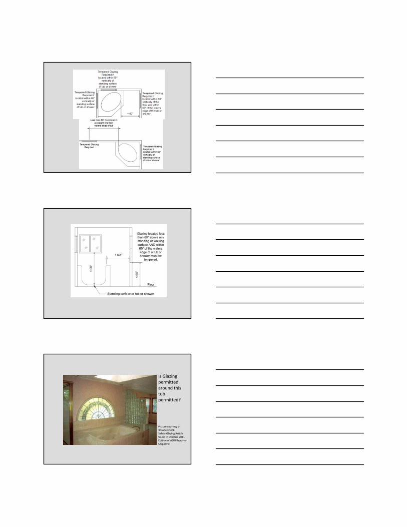
above a walking surface.5. Glazing in enclosures for walls facing hot tubs,
whirlpools, saunas, steam rooms, bathtubs and showers where the bottom of the exposed edge of the glazing is less than 60 inches measured vertically above any standing or walking surface
– Exception:• Glazing more that is more than 60 inches, measured horizontally and in a straight line, from the waters edge of a hot tub, whirlpool or bathtub.
308.4 Hazardous Locations
Picture courtesy of ©Code Check.Safety Glazing Article found in October 2011 Edition of ASHI Reporter Magazine
Glazing used in any railing, regardless of height, must be tempered
Picture courtesy of ©Code Check.Safety Glazing Article found in October 2011 Edition of ASHI Reporter Magazine
Is Glazing permitted around this tub permitted?

308.4 Hazardous Locations
• The following is considered specific hazardous locations for the purposes of glazing:6. Glazing in walls and fences adjacent to indoor
and outdoor swimming pools, hot tubs and spas where the bottom edge of the glazing is less than 60 inches above a walking surface and within 60 inches, measured horizontally and in a straight line, of the waters edge. This applies to single glazing and all panes in multiple glazing.
Picture courtesy of ©Glenn Mathewson.Safety Glazing for Safer Decks Article found in July/August 2007 Edition of Professional Deck Builder Magazine
308.4 Hazardous Locations• The following is considered specific hazardous locations for the
purposes of glazing:
7. Glazing adjacent to stairs, landings and ramps within 36 inches horizontally of a walking surface when the exposed surface of the glazing is less than 60 inches above the plane of the adjacent walking surface
– Exceptions:1. When a horizontal rail is installed on the accessible side(s) of the glazing 34”
to 38” above the walking surface
– Must be capable of withstanding a horizontal load of 50plf without contacting the glass, and
– Be a minimum of 1.5” in cross sectional height.
2. The side of the stairway has a guardrail or handrail, including balusters or in‐fill panels, complying with Sections 311.7.6 & 312 and the plane of the glazing is more than 18 inches from the railing; or,
3. When a solid wall or panel extends from the plane of the adjacent walking surface to 34 to 36 inches above the walking surface and the construction at the top of that wall or panel is capable of withstanding the same horizontal load as a guard.

Where is the 36”dimensioned measured from
at the top of a stair?

308.4 Hazardous Locations• The following is considered specific hazardous locations for the
purposes of glazing:
8. Glazing adjacent to stairways within 60 inches horizontally of the bottom tread of a stairway in any direction when the exposed surface of the glazing is less than 60 inches above the nose of the tread.
– Exceptions:1. The side of the stairway has a guardrail or handrail, including balusters or in‐
fill panels, complying with Sections 311.7.6 & 312 and the plane of the glazing is more than 18 inches from the railing; or,
2. When a solid wall or panel extends from the plane of the adjacent walking surface to 34 to 36 inches above the walking surface and the construction at the top of that wall or panel is capable of withstanding the same horizontal load as a guard.
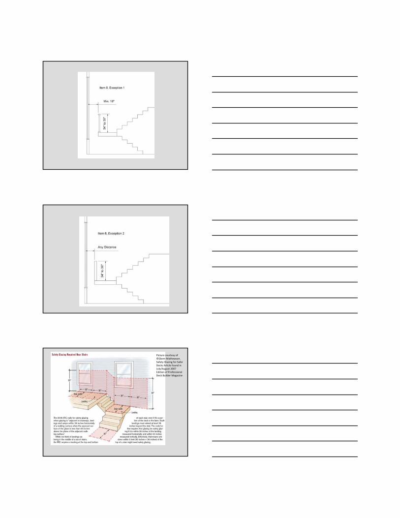
Picture courtesy of ©Glenn Mathewson.Safety Glazing for Safer Decks Article found in July/August 2007 Edition of Professional Deck Builder Magazine
Picture courtesy of ©Glenn Mathewson.Safety Glazing for Safer Decks Article found in July/August 2007 Edition of Professional Deck Builder Magazine
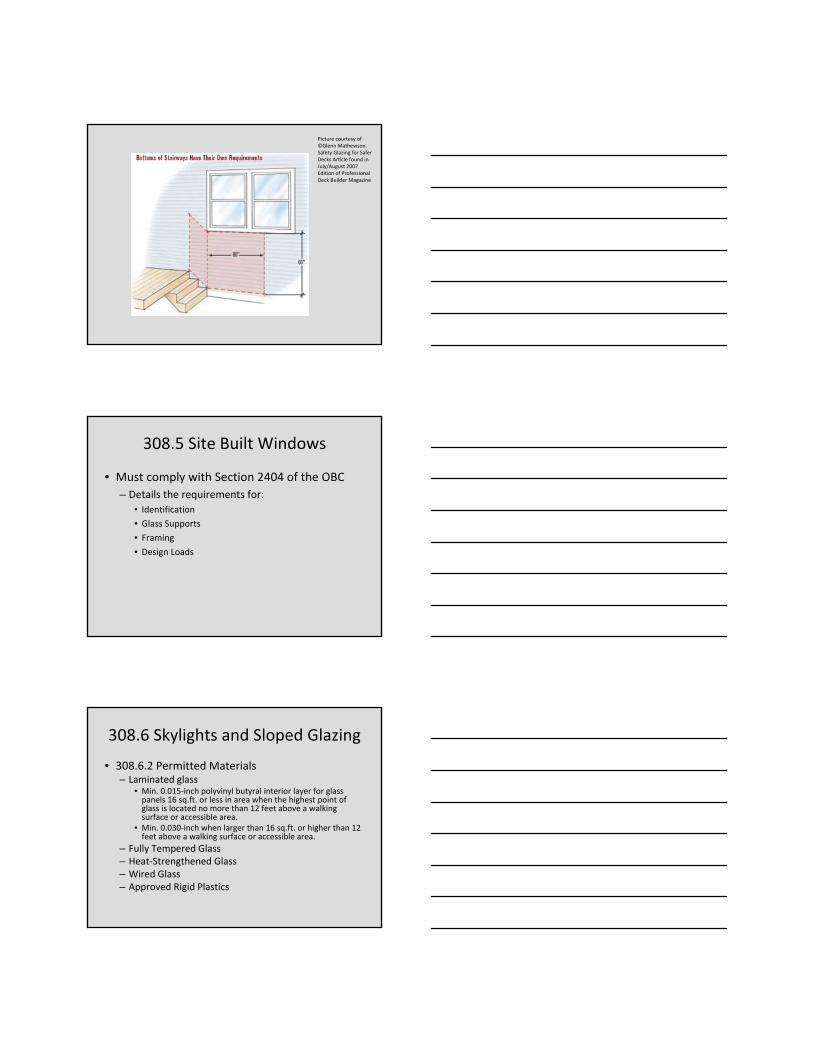
308.5 Site Built Windows
• Must comply with Section 2404 of the OBC
– Details the requirements for:
• Identification
• Glass Supports
• Framing
• Design Loads
308.6 Skylights and Sloped Glazing
• 308.6.2 Permitted Materials– Laminated glass
• Min. 0.015‐inch polyvinyl butyral interior layer for glass panels 16 sq.ft. or less in area when the highest point of glass is located no more than 12 feet above a walking surface or accessible area.
• Min. 0.030‐inch when larger than 16 sq.ft. or higher than 12 feet above a walking surface or accessible area.
– Fully Tempered Glass– Heat‐Strengthened Glass– Wired Glass– Approved Rigid Plastics

308.6 Skylights and Sloped Glazing
• Screens
– Required when fully tempered or heat‐strengthened glass is used (except as detailed in Section 308.6.5)
– Required when the inboard plane of multiple glazed skylights is fully tempered, heat‐strengthened or wired glass (except as detailed in Section 308.6.5)
– Screen and its fastenings must:• Be capable of supporting twice the weight of the glazing
• Be firmly and substantially fastened to the framing members
• Have a mesh opening of no more than 1”x1”
308.6 Skylights and Sloped Glazing
• 308.6.5 Screens not required– Not required for fully tempered or inboard glazing when either of the following conditions are met:1. Glass area is no more than 16 sq.ft. The highest point
is no more than 12 feet above a walking surface, the nominal glass thickness is not more than 3/16”, and (for multiple glazing only) the other panes fully tempered, laminated or wired glass.
2. Glass area is greater than 16 sq.ft. and sloped 30° or less from vertical, and highest point of glass is not more than 10 feet above a walking surface.
308.6 Skylights and Sloped Glazing
• 308.6.6 Glass in Greenhouses– Any glazing material is permitted to be installed without screening in the sloped areas of the greenhouse provided that the height at the ridge does not exceed 20 feet from grade.
• 308.6.8 Curbs and Skylights– When installed in a roof with a pitch flatter than 3/12, unit skylight must be mounted on a curb extending at least 4 inches above the place of the roof unless otherwise specified in the manufacturer’s installation instructions.

308.6 Skylights and Sloped Glazing
• 308.6.9 Testing and Labeling
– Unit skylights must be tested by an approved independent laboratory
– Must be labeled
– Must indicate compliance with AAMA/WDMA/CSA 101/I.S.2/A440.
SECTION 309
Garages & CarportsGarages & Carports
SECTION 310
Emergency Escape & Rescue OpeningsEmergency Escape & Rescue Openings

SECTION 311Means of EgressMeans of Egress
Means of Egress• 311.1 Means of Egress
– All dwellings must be provided with a means of egress per this section.
– Must be a continuous and unobstructed path of vertical and horizontal egress travel from all portions of the dwelling to the exterior of the dwelling at the required egress door without requiring travel through a garage.
Means of Egress• 311.2 Egress Door
– At least one egress door must be provided for each dwelling unit
– Must be side‐hinged
– Must provide a clear opening width of 32” when measured between the face of the door (opened 90°) and stop
– Must provide a clear opening height of 78” measured from top of threshold to bottom of stop
– Must be readily openable from the inside of the dwelling without the use of a key or special knowledge/effort
– Other doors are not required to meet these requirements

Means of Egress• 311.2.1 Garage Access Doors
– Garages must have at least one side‐hinged door not less than 2’‐6” x 6’‐8”
– Door between the garage and dwelling may be used to meet this requirement.
311.3 Floors and Landings at Exterior Doors
• Landing or floor is required on each side of each exterior door
– Width must match width of door served
– Must have a minimum 36” dimension in the direction of travel
– May be sloped up to 2%
• Exception:
– Exterior balconies <60 sq.ft. and only accessible from a door are permitted to have a landing less than 36”.
311.3.1 Floor Elevations at the Required Egress Doors
• Landings or floors at the required egress door must not be more than 1.5” lower than the top of the threshold.– Exception:
• May be located no more than 8.25” below the top of the threshold provided the door does not swing over the landing or floor
• When exterior landings or floors serving the required egress door are not at grade, they must have an access to grade by means of a ramp (Section 311.8) or a stairway (Section 311.7).

311.3.2 Floor Elevations for Other Exterior Doors
• Landings or floors serving exterior doors, other than the required egress door, may be located no more than 8.25” below the top of the threshold– Exception:
• A landing is not required where a stairway of two or fewer risers is located on the exterior side of the door, provided the door does not swing over the stairway.
• 311.1.3 Storm and screen doors are permitted to swing over all exterior stairs and landings
Vertical Egress & Construction
• 311.4 Vertical Egress– Egress from finished levels, including attics and basements not provided with an egress door, must be by a ramp (Section 311.8) or stairway (Section 311.7)
• 311.5 Construction– 311.5.1 Attachment
• Exterior landings, decks, balconies, stairs and similar facilities must be positively anchored to the primary structure to resist vertical and lateral forces, or be designed as self‐supporting.
• Attachment cannot rely on toenails or nails subject to withdrawal
311.6 Hallway
• Must be at least 3 feet wide.

311.7 Stairways
• 311.7.1 Width
– Must not be less than 36” in clear width at all points between the permitted guardrail height and required headroom.
– Handrails may project no more than 4.5” on either side of the stairway.
– Exception:
• The width of spiral stairways complying with Section 311.7.9.1
311.7.2 Headroom
• Minimum 6’‐8” measured vertically from the sloped line adjoining the tread nosing or from the floor surface of the landing/platform on that portion of the stairway
• Exception:
– Where the nosing of treads at the side of a flight extend under the edge of a stair opening, the floor opening may project horizontally into the required headroom a maximum of 4.75”
311.7.3 Walkline
• For winder treads:– Shall be concentric to the curved direction of travel through the turn
– Must be located 12 inches from the side where the winders are narrower.
– The 12 inch dimension must be measured from the widest point of the clear stair width at the walking surface of the winder.
– If winders are adjacent within the flight, the point of the widest clear stair width of the adjacent winders must be used.

Walkline
311.7.4 Stair Treads and Risers
• All dimensions and dimensioned surfaces must be exclusive of carpets, rugs or runners.
Stair Geometry
• 311.7.4.1 Riser Height
• 311.7.4.2 Tread Depth
• 311.7.4.3 Profile
Closed risers not required when the total rise of the stairs is 30 inches or less.

Stair Geometry
• 311.7.4.1 Riser Height
• 311.7.4.2 Tread Depth
• 311.7.4.3 Profile
Stair Geometry and Landings
311.7.5 Landings for Stairways
• There shall be a floor or landing at the top and bottom of each stairway– Exception:
• Not required at the top of an interior flight of stairs, including stairs in an enclosed garage, provided a door does not swing over a landing
– Maximum 12’ vertical rise between floor levels or landings
– The width of each landing must be at least the width of the stairway.
– Each landing must be at least 36” measured in the direction of travel.

311.7.7 Handrails
• Required on at least one side of a stairway that has four of more risers.
• Must be located between 34” to 38” above the tread nosing or finished surface of a ramp.– Exceptions
• The use of a volute, turnout or starting easing shall be allowed over the lowest tread
• Handrail fittings or bendings used to provide continuous transitions between flights or at the start of a new flight may exceed the maximum height.
Handrails
Handrails
• 311.7.7.2 Continuity– Handrails must be continuous for the full length of the flight
– Must starts at the point directly above the lowest tread and end at the point directly above the highest tread of a flight
– Handrail ends must be returned into a wall or terminate in newel posts or safety terminals.
– Must have a space at least 1.5” between the handrail and wall
• May not project more than 4.5” into the required 36”stairway width.

Handrails• 311.7.7.2 Continuity• Exceptions:
– May be interrupted by a newel post at a turn
– The use of a volute, turnout, starting easing or starting newel is allowed over the lowest tread.
– Two or more separate rails are considered continuous if the termination of the rails occur over a single tread and positioned within 4 inches of each other.
Handrails
• 311.7.7.3 Grip Size
Handrails
• 311.7.7.3 Grip Size

Handrails
311.7.9 Special Stairways
• 311.7.9.1 Spiral Staircases
– Minimum 26” clear width at and below the handrail
– Minimum 7 ½” tread at the 12‐inch walk line
– Maximum 9 ½” riser height
– All treads must be identical
– Minimum 6’‐6” headroom

Special Stairways
• 311.7.9.2 Bulkhead Enclosures
– Stairways serving bulkhead enclosures that are not part of the required building egress and provide access from the outside grade level to a basement are exempt from the requirements of Sections 311.3 and 311.7 given:
• The maximum height from basement finished floor to grade adjacent to the stairway does not exceed 8 feet, and,
• The grade level opening to the stairways is covered by a bulkhead enclosure with hinged doors or other approved means.
311.8 Ramps
Maximum ramp slope = 1 unit vertical /8 units horizontal
(12.5%)
SECTION 312 SECTION 312 GUARDSGUARDS

312.1 Where Required
• Along open‐sided surfaces, including stairs, ramps and landings, that are located more than 30 inches above a floor or grade below at any point within 36 inches horizontally to the edge of the open side– Insect screening is not considered a guard
312.2 Height
• Required guard must be at least 36 inches high measured vertically above the adjacent walking surface, fixed seating or the line connecting leading edges of the treads
Height
• 312.2 Minimum 36” Height
– Exceptions
• Guards on open side of stairs must have a height of at least 34 inches measured vertically from a line connecting the leading edges of the treads
• Where the top of the guard also serves as a handrail on the open sides of stairs, the top of the guardrail must be located between 34” and 38” measured vertically from a line connecting the leading edges of the treads.

312.2.3 Opening Limitations
SECTION 313 SECTION 313
AUTOMATIC FIRE AUTOMATIC FIRE
SPRINKLERSPRINKLER SYSTEMSSYSTEMS
Automatic Fire Sprinkler Systems
• Fire Sprinklers are not required in:
– In structures comprised of 1, 2 or 3 Family Dwellings, or
– In R‐3 structure designs qualifying to use the RCO for compliance.

Automatic Fire Sprinkler Systems
• When non‐required automatic fire sprinkler systems are specified for installation in structures comprised of 1, 2 or 3 family dwellings, or in R‐3 structure designs qualifying to use the RCO for compliance, the design and installation of the system (to the extent of the intended installation, must comply with one of the following:
– NFPA 13 typically commercial full coverage
– NFPA 13R typically residential, mostly multi‐family
– NFPA 13D typically single family, domestic supply
– Section 2904 of this code
SECTION 314 SECTION 314 Smoke AlarmsSmoke Alarms
314.1 Smoke Detection and Notification
• All smoke alarms must be listed per UL 217 and installed per this code and the household fire warning equipment provisions of NFPA 72.

314.2 Smoke Detection Systems
• Household fire alarm systems installed per NFPA 72 that include smoke alarms, or combination of smoke detector and audible notification device installed as required by this section is permitted.– Must provide the same level of smoke detection and alarm as required by this section for smoke alarms.
– When installed using a combination of smoke detector and audible notification device(s), it must become a permanent fixture of the occupancy and owned by the homeowner.
– The system must be maintained per NFPA 72.
• Exception:– Where smoke alarms are provided meeting Section 314.4.
314.1 Location• Smoke alarms must be located in the following locations:
1. In each sleeping room2. Outside each separate sleeping area in the immediate
vicinity of the sleeping rooms3. On each additional story of the dwelling, including
basements and habitable attics• Not required in crawl spaces or uninhabitable attics• Split levels without intervening door between adjacent levels, the
smoke alarm placed on the upper level shall suffice for the adjacent lower level– Lower level must be less than one full story below the upper level.
• When more than one smoke alarm is required in a dwelling, all of the alarms must be interconnected so that the actuation of one alarm will active all of the alarms in the individual unit.
314.2 Location, continued…
• When more than one smoke alarm is required in a dwelling, all of the alarms must be interconnected so that the actuation of one alarm will active all of the alarms in the individual unit.

314.2 Location, continued…
314.3.1 Alterations, Repairs and Additions
• When alterations or additions requiring an approval are made to the spaces described in Items 1 and 2 of Section 314.3, smoke alarms must be provided in those spaces as required for a new dwelling.
• When one or more sleeping rooms are added or created in an existing dwelling, the new sleeping rooms and the immediate vicinity outside of each sleeping room must have smoke alarms as required for a new dwelling.
314.3.1 Alterations, Repairs and Additions, continued…
• Exceptions
1. Work involving exterior surfaces of a dwelling, the addition/replacement of windows, or the addition of a porch or deck are exempt from the requirements of this section.
2. Installation or alteration of plumbing or mechanical systems are exempt from the requirements of this section.

314.4 Power Sources• Must receive their primary power from the building wiring system
when served by a commercial source.
• Must be equipped with a battery back‐up system.
• Wiring must be permanent and without a disconnection switch
• Must be interconnected
• Exceptions:
1. Buildings without commercial power may use alarms that are battery operated.
2. Interconnection and hard‐wiring of alarms in existing areas are not required when the alterations/repairs do not result in the removal of interior wall or ceiling finishes exposing the structure, unless there is an attic, crawl space or basement available which couldprovide access for hard wiring and interconnection without removal of interior finishes.
SECTION 315 SECTION 315 Carbon Monoxide AlarmsCarbon Monoxide Alarms
Carbon Monoxide Alarms
• Carbon monoxide alarms are required in all new construction, as well as existing dwellings where work being performed requires a permit (an approval), (But only:) when the dwelling has an attached garage or fuel‐fired appliances.
• Must be installed outside of each sleeping area in the immediate vicinity of the bedrooms.
• Single station carbon monoxide alarms must be listed as complying with UL 2034 and installed per this code and the manufacturer’s installation instructions.

Carbon Monoxide Alarms cont’d.
SECTION 316SECTION 316Foam PlasticsFoam Plastics
SECTION 317
Protection of Wood and Wood Based Products Against Decay

317.1 Location Required
• The locations listed on the following slides are locations where protection of wood and wood based products from decay must be provided.
• Pressure‐treatment must be in accordance with AWPA U1 for the species, product, preservative and end use.
• Preservatives must be listed in Section 4 of AWPA U1.
• Visit www.awpa.com/standards/ucs.asp for an excerpt of the AWPA U1 Standard
AWPA U1
Courtesy of AWPA
AWPA U1 Categories
Information courtesy of AWPA
• UC1 INTERIOR/DRY– Wood and wood based materials used in interior construction not in contact with the ground or foundation. Such products are protected from weather and interior sources of water such as leaking plumbing, condensate, pools and spas. Examples are interior furniture, construction furnishing, and millwork.
• UC2 INTERIOR/DAMP– Wood and wood based materials used for interior construction that are not in contact with ground, but may be subject to dampness. These products are continuously protected from the weather but may be exposed to occasional sources of moisture. Examples are interior beams, timbers, flooring, framing, millwork and sill plates.

AWPA U1 Categories
Information courtesy of AWPA
• UC3A ABOVE GROUND Protected– Wood and wood‐based materials used in exterior construction that
are coated and not in contact with the ground. Such products may be exposed to the full effects of weather, such as vertical exterior walls or other types of construction that allows water to quickly drain from the surface. Examples are coated millwork, siding and trim.
• UC3B ABOVE GROUND Exposed– Wood and wood based materials used in exterior construction and not
in contact with the ground. Materials do not require an exterior coating, but may be finished to achieve a desired aesthetic appearance. Materials are used for a variety of applicants in either horizontal and vertical positions such as decking, sills, walkways, railings and fence pickets.
– Note: Retentions above the minimum specified for materials in this use category may be required for products such as crossarms where the individual components are difficult to maintain, repair or replace and are critical to the performance and safety of the entire system.
AWPA U1 Categories
Information courtesy of AWPA
• UC4A GROUND CONTACT General Use– Wood and wood‐based materials in contact with the ground,
fresh water, or other situations favorable to deterioration. Examples are fence posts, deck posts, guardrail posts, structural lumber, timbers and utility poles located in regions of low natural potential for wood decay and insect attack.
• UC4B GROUND CONTACT Heavy Duty– Wood and wood based materials used in contact with the
ground either in sever environments, such as horticultural sites, in climates with a high potential for deterioration, in critically important components such as utility poles, building poles and permanent wood foundations, and wood used in salt water splash zones. This category includes utility poles used in moist temperate climates.
AWPA U1 Categories
Information courtesy of AWPA
• UC4C GROUND CONTACT Extreme Duty
– Wood and wood based materials used in contact with the ground either in very sever environments or climates demonstrated to have extremely high potential for deterioration, in critical structural components such as land and fresh water piling and foundation piling, and utility poles located in semi‐tropical to tropical environments.

317.1 Location Required, continued…
1. Wood joists or the bottom of a wood structural floor when closerthan 18 inches, or wood girders when closer to 12 inches, to exposed ground in crawl spaces or unexcavated area located within the periphery of the building foundation.
2. All wood floor members resting on concrete or masonry foundation walls and is located less than 8 inches from the exposed ground.
3. Sills and sleepers on a concrete or masonry slab that is in direct contact with the ground, unless separated from such slab by an impervious moisture barrier.
4. The ends of wood girders bearing on exterior masonry or concrete walls having clearances of less than ½” on tops, sides and ends.
317.1 Location Required, continued…
5. Wood siding, sheathing and wall framing within 6 inches from the ground, or less than 2 inches measured vertically from concrete steps, porch & patio slabs, and similar horizontal surfaces exposed to the weather.
317.1 Location Required, continued…
6. Wood structural members supporting moisture‐permeable floors or roofs that are exposed to the weather (i.e. concrete or masonry slabs), unless separated from such floors or slabs by an impervious moisture barrier.
7.Wood furring strips or other wood framing members fastened directly to interior or exterior masonry or concrete walls below grade, except where an approved vapor retarder is placed between the wall and framing members.
317.1.1 Field Treatment ‐ Deleted

317.1.2 Ground Contact
• Pressure‐preservative‐treated wood must be used when wood is:– In contact with ground– Embedded in concrete in direct contact with the ground
– Embedded in concrete that is exposed to the weather and supports permanent structures intended for human occupancy
• Untreated wood may only be used where it is entirely below groundwater level or continuously submerged in fresh water.
317.1.3 Geographical Areas
• In areas where experience has shown a specific need for additional protection, naturally durable or pressure‐preservative‐treated lumber must be used.
• Structural wood members used to support buildings, balconies or similar appurtenances subject to weather without adequate protection must be used.
• Depending on local experience, such members may include:1. Horizontal members (girders, joists and decking)
2. Vertical members (posts, poles and columns)
3. Both vertical and horizontal members
317.1.4 Wood Columns
• Wood columns must be naturally decay resistant or pressure‐preservative‐treated wood.
• Exceptions:1. Columns exposed to weather or in basements when
supported by concrete piers or metal pedestals project 1 inch above a concrete floor or 6 inches above exposed earth
• Earth must be covered by an approved impervious moisture barrier
2. Columns located within an enclosed crawl space or unexcavated areas wen supported by a concrete pier or metal pedestal at least 8 inches from the exposed earth
• Earth must be covered by an approved impervious moisture barrier.

317.1.5 Exposed Glued‐Laminated Timbers
• Must be pressure‐treated with preservative, or manufactured from naturally durable or preservative‐treated wood when any portion of the timber is exposed to weather and not properly protected by a roof or covering.
317.2 Quality Mark
• Lumber and plywood that is required to be pressure‐preservative‐treated per Section 318.1 must be labeled by an approved inspection agency.
• 317.2.1 Required Information. Quality mark must have the following information:1. Identification of the treatment plant.2. Type of preservative.3. The minimum preservative retention.4. End use for which the product was treated.5. Standard to which the product was treated.6. Identity of the approved inspection agency.7. The designation of “Dry,” if applicable.
Example Tag
Picture courtesy of AWPA

317.2 Quality Mark
• 317.2.1 Required Information
• Exception
– Lumber less than 1 inch nominal thickness, nominal 1x5, 2x4 or lumber less than 3 feet long must have a quality mark that is either stamped on the face of exterior pieces or by end labeling of at least 25% of the pieces in a bundled unit.
317.3 Fasteners and Connectors
• Fasteners and connectors in contact with preservative‐treated wood and fire‐retardant‐treated wood must comply with this section.
• Coating weights for zinc‐coated fasteners must comply with ASTM A 153.– 317.3.1 Fasteners for preservative‐treated wood– 317.3.2 Fastenings for wood foundations– 317.3.3 Fasteners for fire‐retardant‐treated wood used in exterior applications or wet/damp locations
– 317.3.4 Fasteners for fire‐retardant‐treated wood used in interior applications.
317.3.1 Fasteners for Preservative‐Treated Wood.
• Fasteners‐must be hot‐dipped zinc‐coated galvanized steel, stainless steel, silicon bronze or copper
• Connectors‐Coating types and weights for connectors in contact with treated wood must follow the connector manufacturer’s recommendations
• In the absence of the manufacturer’s recommendations, a minimum of ASTM A 653 type G185 zinc‐coated galvanized steel (or equivalent) must be used.
• Exceptions:1. ½ inch diameter or larger steel bolts2. Fasteners (other than nails and timber rivets) are allowed to
be mechanically deposited zinc coated steel with coating weights per ASTM B 695, Class 55 minimum.

317.3.2 Fastenings for Wood Foundations
• Must follow AF&PA Technical Report No. 7
Fasteners in Fire‐Retardant‐Treated Wood
• 317.3.3 Exterior or Wet/Damp Locations– Must be hot‐dipped zinc‐coated galvanized steel, stainless steel, silicon bronze or copper.
– Fasteners (other than nails and timber rivets) are allowed to be mechanically deposited zinc coated steel with coating weights per ASTM B 695, Class 55 minimum.
• 317.3.4 Interior Applications– Must follow the manufacturer’s recommendations.– In the absence of manufacturer’s recommendations, Section 317.3.3 shall apply.
317.4 Wood/Plastic Composites
• Composites used in exterior deck boards, stair treads, handrails and guardrail systems must bear a label indicating the required performance levels and demonstrating compliance with ASTM D 7032.
• Must be installed per the manufacturer’s instructions.

318.1 Subterranean Termite Control Methods
• Ohio is subject to termite damage per Table 301.2(1)• One of the following, (or combination of the following) methods or protection must be followed:1. Chemical termiticide treatment per Section 318.2.2. Termite baiting system installed and maintained per its
listing.3. Pressure‐preservative‐treated wood per Section 317.1.4. Naturally durable termite‐resistant wood.5. Physical barriers per Section 318.3 and located per
Section 318.1.6. Cold‐formed steel framing per Sections 505.2.1 and
603.2.1.
318.1.1 Quality Mark
• Required pressure‐preservative‐treated lumber and plywood must have the quality mark of an approved inspection agency.
• 318.1.2 Field Treatment‐Deleted.
Chemical Treatment and Barriers
• 318.2 Chemical Termiticide Treatment– Must include soil treatment and/or field applied wood treatment.
– The concentration and application must be in strict accordance with the termiticide label.
• 318.3 Barriers– Approved physical barriers (i.e. metal or plastic sheeting or collars specifically designed for termite prevention) must be installed to prevent termite entrance.
– May only be placed at the top of a foundation wall when it is used in combination with another method of protection.

318.4 Foam Plastic Protection
• Provides requirements for areas designated as “very heavy” in Figure 301.2(6)
– Ohio is designated as “moderate to heavy”
SECTION 318
Site AddressSite Address
319 Site Address
• Address or building numbers or building ID must be:
– in a position plainly legible (recognizable & readable) from the street
– Method used must be approved

SECTION 320
AccessibilityAccessibility
Accessibility
• 1, 2 & 3 Family Dwelling Structures
– No mandatory accessibility provisions apply
– When an accessible feature is intended to be installed or added, the element must be designed and installed in accordance with ICC/ANSI A117.1‐2009 (see 320.1)
– When accessibility is intended inside the dwelling, the criteria is listed in Chapter 10 of the ICC/ANSI A117.1 for Accessible, Type A and Type B units.

Accessibility• Structures with more than 3 dwellings
– The ICC/ANSI A117.1‐2009 is referenced for design and construction compliance
– All dwellings must be in compliance with the Type B requirements in ICC A117.1 Chapter 10 unless exempted in 320.4
• Units in non‐elevator buildings when:– The living space within a unit is on more than one floor
– Units on floors other than a grade level floors (units on one floor level must comply)
• In multi‐floor dwellings in buildings with elevators, the floor accessed by the elevator must have certain amenities and comply with the Type B criteria
• Units in buildings with certain extreme topography
– Common and public use areas regulated by the OBC
SECTION 321SECTION 321
Elevators & Platform liftsElevators & Platform lifts
Elevators & Platform lifts
• Elevators, LULAs and Platform lifts within dwellings and as accessory components, regulated by the Residential Building Official
– Passenger elevators & LULAs (limited use limited application) must comply with ASME A17.1
– Platform Lifts must comply with ASME A18.1
– When intended to be accessible, ICC/ANSI A117.1 applies also

SECTION 322SECTION 322
FloodFlood‐‐Resistant ConstructionResistant Construction
322 General
• 322.1 Except where approved by the Flood Plain Administrator having jurisdiction, any building or portion thereof constructed in flood hazard areas (including A or V Zones) per Table 301.2(1) must be designed and constructed per Section 322.– Buildings or portion thereof located within identified floodways must be designed and constructed per ASCE 24‐05 (Flood Resistant and Design Construction)
Structural Systems and Construction
• 322.1.1 Alternative Provisions– Alternative for projects in coastal high‐hazards (not applicable to Ohio)
• 322.1.2 Structural Systems– Must be designed, connected and anchored to resist flotation, collapse or permanent lateral movement due to loads and stresses from flooding equal to the design flood elevation.
• 322.1.3 Flood‐Resistant Construction– Structures located in areas prone to flooding must be constructed so as to minimum flood damage.

322.1.4 Establishing the Design Flood Elevation
• Used to define areas prone to flooding
• Must be the higher of:1. The base flood elevation at the depth of peak
elevation of flooding which has a 1 percent (100‐year flood) or greater chance of being equaled or exceeded in any year; or,
2. The elevation o f the design flood associated with the area designated on a flood hazard map adopted by the community, or otherwise legally designated.
322.1.4.1 Determination of Design Flood Elevation
• If not specified, the Building Official is authorized to required the applicant to:– Obtain and reasonably use data available from a federal, state or other source; or,
– Determine the design flood elevation per accepted hydrologic and hydraulic engineering practices used to define special flood hazard areas.
• Must be undertaken by a registered design professional• Must document that the technical methods used reflect currently accepted engineering practice.
• All studies, analyses and computations must be submitted in sufficient detail to allow thorough review and approval.
322.1.4.2 Determination of Impacts
• In riverine flood hazard areas where the design flood elevations are specified but floodways have not been designated:
– The applicant must demonstrate that the effect of the proposed building or structure (including fill and combined with all other existing or anticipated encroachments) will not increase the design flood elevation more than one foot at any point within the jurisidiction
322.1.5 Lowest Floor
• Shall be the floor of the lowest enclosed area (including basements) but excluding any unfinished flood‐resistant enclosure that is used solely for:– Vehicle parking
– Building access
– Limited storage
• These enclosures shall not be built so as to render the building or structure in violation of this code.
322.1.6 Protection of Mechanical and Electrical Systems
• Must be located at or above the elevation required in Section 322.2.
• If these systems are replaced as a part of substantial improvement, then compliance with this section is required.
• Must not be mounted on or penetrate through walls instead to break away under flood loads.– Exception: May be located below the elevation required in
Section 322.2, provided that they are designed and installed to prevent water from entering or accumulating within the components and to resist hydrostatic and hydrodynamic loads and stresses during the occurrence of flooding per ASCE 24.
– Electrical systems may be located below the required elevations provided they conform to the provisions for wet locations.
322.1.7 Protection of Water Supply and Sanitary Sewage Systems
• New and replacement water supply systems must be designed to minimize or eliminate infiltration of flood waters into the system per the Ohio Plumbing Code.
• New and replacement sanitary sewage systems must be designed to minimum or eliminate infiltration of floodwaters into systems and discharges from systems into floodwaters per the Ohio Plumbing Code.

322.1.8 Flood‐Resistant Materials
• Building materials used below the required elevation per Section 322.2 must comply with the following:1. All wood, including floor sheathing, must be
pressure‐preservative‐treated per AWPA U1 or be decay‐resistant heartwood. Preservatives must be listed in Section 4 of AWPA‐U1.
2. Materials and installation methods used for flooring, interior/exterior walls and wall coverings must conform to FEMA/FIA‐TB‐2.
322.1.10 As‐Built Elevation Documentation
• A registered design professional must prepare documentation of the elevations specified in Section 322.2.
• Note: 322.1.9 was deleted.
322.2 Flood Hazard Areas (including A Zones)
• All areas that have been determined to be prone to flooding, but not subject to high velocity wave action, shall be designated as flood hazard areas.
• Flood hazard areas that have been delineated as subject to wave heights between 1.5 feet and 3 feet shall be designated as Coastal A Zones.
• All buildings or structures located in whole or in part of these areas must be designed and constructed per Sections 322.2.1 through 322.2.3.

322.2.1 Elevation Requirements
1. Buildings and structures in flood hazard areas not designated as Coastal A Zones must have the lowest floor areas elevated to or above the design flood elevation.
2. Buildings or structures in Coastal A Zones must have the lowest floors elevated to or above the base flood elevation plus one foot, or to the design flood elevation, whichever is higher.
322.2.1 Elevation Requirements, continued…
3. In areas of shallow flooding (AO Zones), buildings and structures shall have the lowest floor (including basements) elevated at least as high above the highest adjacent grade as the depth number specified in feet on the FIRM, or at least two feet if a depth number is not specified.
4. Basement floors that are below grade on all sides shall be elevated to or above the design flood elevation.
Exception: Enclosed areas below the design base flood elevation, including basement whose floors are not below grade on all sides, shall comply with Section 322.2.2.
322.2.2 Enclosed Area Below Design Flood Elevation
• Enclosed spaces, including crawl spaces, that are below the design flood elevations shall:1. Be used solely for parking of vehicles, building access or
storage.
2. Be provided with flood openings that meet the following criteria:
• Each area must have at least two openings on different walls
• The total net opening of all openings must be 1sq.in. for each foot of enclosed area– Otherwise sealed documents must be submitted showing that the
designed openings will provide for equalization of hydrostatic flood forces on exterior walls by allowing for the automatic entry and exist of floodwaters as specified in Section 2.6.2.2 of ASCE 24.

322.2.2 Continued….
• 2. Food openings that meet the following criteria, continued…
– The bottom of the opening must be a maximum one foot above the adjacent ground level
– Must not be less than three inches in any direction in the plane of the wall.
– Any louvers, screens or other opening covers must allow the automatic floor of floodwaters into and out of the enclosed area.
322.2.3 Foundation Design and Construction
• All foundation walls must meet Chapter 4.– Exception: Unless designed per Section 404:
1. The unsupported height of 6‐inch plain masonry walls shall be no more than 3 feet.
2. The unsupported height of 8‐inch plain masonry walls shall be no more than 4 feet.
3. The unsupported height of 8‐inch reinforced masonry walls shall be no more than 8 feet.
For the purpose of this exception, unsupported height is the distance from the finished grade of the under‐floor space and the top of the wall.
322.3 Coastal High Hazard Areas (including V Zones)
• Describes requirements for construction in areas designated as coastal high‐hazard areas.

SECTION 323SECTION 323
Storm SheltersStorm Shelters
323 Storm Shelters
• Detached storm shelters and safe rooms within a building used for safe refuge from weather events must comply with the RCO and ICC/NSSA‐500 (2008 Standard for the Design and Construction of Storm Shelters)
SECTION 324SECTION 324
Post Frame Accessory StructuresPost Frame Accessory Structures

Post Frame ‐ Limitations 1. Residential accessory structures2. Single Story3. Solid exterior structural sheathing or metal roof, and solid
wall panels4. No attic storage (attic storage would require engineered
design trusses)5. Maximum building width of 36 feet including overhang6. Maximum wall height of 16 feet7. Maximum mean roof height of 20 feet, and8. Maximum post spacing of 8 feet (unless truss sit directly
on post)
Limitations
• “Post and frame structures and portions thereof outside the above structural limitations of this standard shall be accompanied by structural calculations as required by the residential building official or designed under the provisions of section 116.2 of the Residential Code of Ohio (RCO). Post and frame structures shall comply with the structural design requirements of Section 301 of the RCO.”
324.2 Definition
• Primary members– Wood posts– Beams– Single span roof trusses or ceiling joist and rafters
• Secondary members– Wood roof purlins– Wall girts– Bracing– Sheathing
• Primary members and secondary members where all loads are transmitted from the sheathing and the secondary members to the primary members which transfer all combined loads to the soil through vertical posts bearing on footings embedded in the ground.
• See Figure 324.

324.3 Footings and Foundations
• Must comply with Section 401.
• Shall have poured‐in‐place concrete footings below all posts
• Top of footing shall be minimum 48 inches below finished grade
• Diameters per Table 324.3.
324.4 Columns and wall construction
• Columns must be:
– (3) ply un‐spliced,
– (3) ply reinforced splice or solid wood
• At least 4x6 nominal
• Comply with treated requirements of Section 317.
• Ends restrained to prevent lateral displacement

324.4.1 Uplift protection
• Columns must have uplift protection by using one of the following:
– (2) 2x6x12” treated uplift blocks attached to side of the base of the column
324.4.1 Uplift protection
– 12 inch tall concrete collar on top of footing and around post with 2‐#5x9 in. rebar placed through the post at 3 in. and 9 in. from bottom of post in opposite directions. Rebar must be 1 ½” from the soil
324.4.1 Uplift protection
Exact language found in 2013 RCO…
Should be ‘and’

324.4 Column and wall construction
• 324.4.2 Column spacing limited to 8 ft. unless truss sits directly onto post
• Note: several remaining sections/footnotes limits spacing to 8ft.
• 324.4.3 Skirt boards must be treated per Section 317 and fastened per Table 324.7
• 324.4.4 Wall girts must be minimum 2x4 nominal and spaced max. 24” o.c.
324.4.5 Load Bearing Beams and Headers
• Beams and headers must comply with Table 502.5(1) (with exceptions)
Load Bearing Beams and Headers Exceptions
1. Not required if trusses or ceiling joists/rafters bear directly on the columns
2. “Openings on the gable end walls supporting a door or roof total load not exceeding 5 sq.ft. per lineal feet of wall area that require beams or headers must be sized per Table 324.4.5”

324.4.6 Bracing
• Prescribes two ways to provide lateral resistance1. Compliance with Section R602.102. Install 2x6 diagonal braces between two adjoining
columns at 8 ft. o.c. or multiple spacing totaling a minimum 8 ft. o.c. where the post spacing design is less than 8’ o.c.
• Placed from top of header or girt to the next adjoining column at the skirt board.
• Installed on each side of the building• Spaced 25’ o.c. and within 12’ of all ends• Fasten per table 324.7• Splices of diagonal bracing due to excessive length must lap over two consecutive wall girts.
324.4.7 Beam Attachment to Column
• Beams must be connected to columns by one of the following:
1. Bolts that are ½ inch diameter through‐bolted to the side of the column
2. Bolts that are ½ inch diameter, directly attached to a 3‐ply column notch, enclosing the truss or rafter at the top of the column
3. Other fasteners with minimum shear values per Table 324.4.7
324.4.7 Beam Attachment to Column
• 324.4.7.1 Number of fasteners– The minimum number
of through bolts or other fasteners with minimum shears or withdraw values per Table 324.4.7.
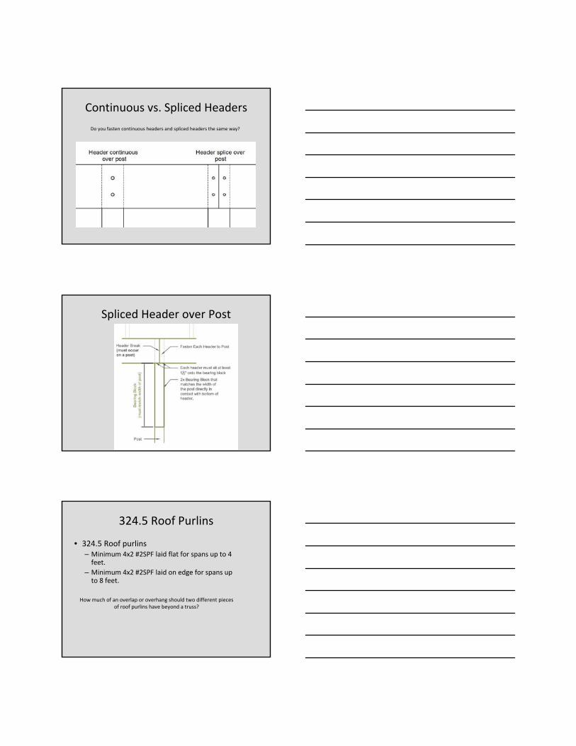
Continuous vs. Spliced Headers
Do you fasten continuous headers and spliced headers the same way?
Spliced Header over Post
324.5 Roof Purlins
• 324.5 Roof purlins– Minimum 4x2 #2SPF laid flat for spans up to 4 feet.
– Minimum 4x2 #2SPF laid on edge for spans up to 8 feet.
How much of an overlap or overhang should two different pieces of roof purlins have beyond a truss?
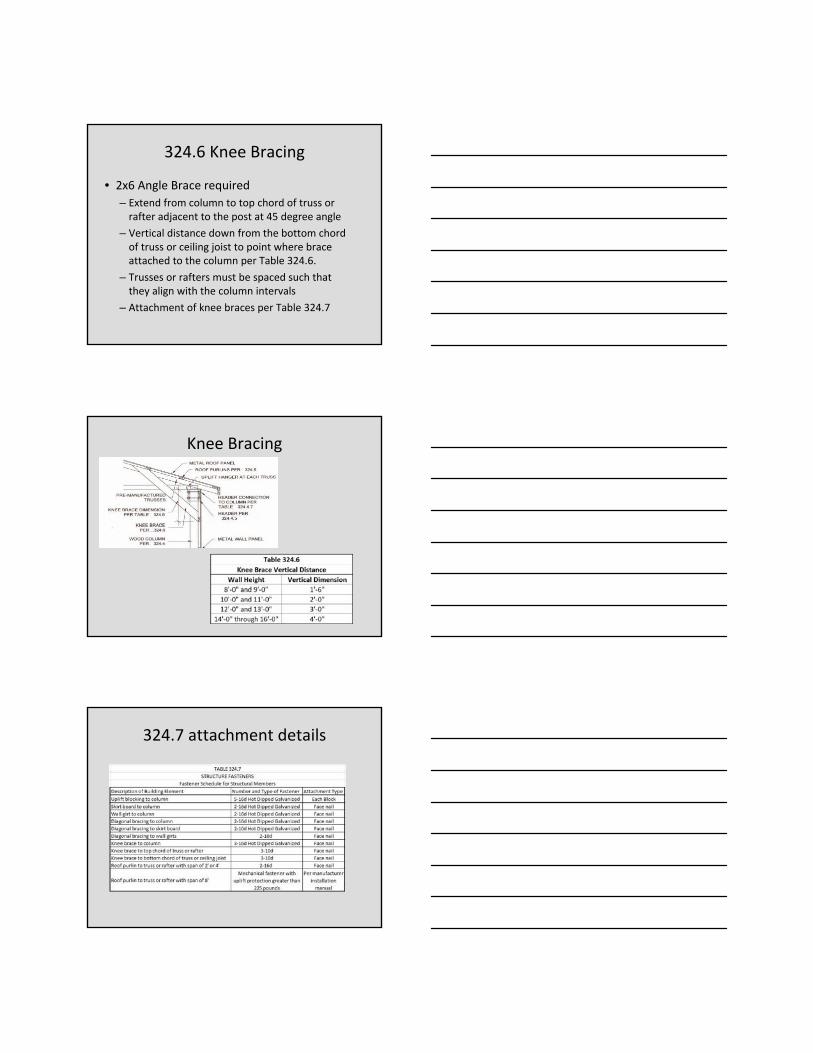
324.6 Knee Bracing
• 2x6 Angle Brace required
– Extend from column to top chord of truss or rafter adjacent to the post at 45 degree angle
– Vertical distance down from the bottom chord of truss or ceiling joist to point where brace attached to the column per Table 324.6.
– Trusses or rafters must be spaced such that they align with the column intervals
– Attachment of knee braces per Table 324.7
Knee Bracing
324.7 attachment details

Ohio Board of Building Standards6606 Tussing RdReynoldsburg, Ohio 43068(614) 644‐2613http://www.com.ohio.gov/dico/BBS.aspx