reshaping ultrashort light pulses in resonant photonic crystals
TRANSCRIPT

1Ulcsp(
bG3p
pasa(ltp
wrstiflesgtpa
Zhao et al. Vol. 23, No. 9 /September 2006 /J. Opt. Soc. Am. B 1981
Reshaping ultrashort light pulsesin resonant photonic crystals
Ji Zhao, Juntao Li, Huiguo Shao, Jiwen Wu, and Jianying Zhou
State Key Laboratory of Optoelectronic Materials and Technologies, Sun Yat-sen University,Guangzhou 510275, China
Kam Sing Wong
Department of Physics, Hong Kong University of Science and Technology, Hong Kong
Received March 15, 2006; accepted May 12, 2006; posted May 17, 2006 (Doc. ID 68860)
Ultrashort light pulses propagating through a resonant photonic crystal can be reshaped to shorter durationoutput through self-induced transparency. The reshaping process is shown to result from the unique transmis-sion behavior of light pulses through the photonic structure. Pulse compression and pulse merging, with whichmultipeak optical pulses can be evolved to give rise to a single-peak, high-quality transmitted pulse output, areobtained. The pulse propagation in a resonant photonic crystal is compared with that in a bulk atomic medium,which shows that the effect of pulse reshaping is much more powerful in the former than in the latter. © 2006Optical Society of America
OCIS codes: 320.5540, 320.7110, 270.5530.
Sct2bsctw
2Ilt(ot
dttv
w=
. INTRODUCTIONltrashort light pulses can be generated directly from a
aser source using the mode-locking technique.1 Pulseompression with nonlinear optical methods to achieve ahorter duration pulse is also commonly used.2 Among theulse compression techniques, self-induced transparencySIT) was proposed and demonstrated some years ago.3,4
The pulse compression with SIT in bulk medium isased on the stability condition of 2� pulses of the sine-ordon equation. For example, an input laser field of area� will evolve to a 2� pulse, resulting in a significantulse compression.3–5
SIT also occurs in periodical atomic layers. A resonanthotonic crystal (RPC) is such a device that atomic layersre periodically arranged with the adjacent atomic layereparation a, related to the resonant wavelength of thetom �0 by �0=2a.6 If the input light field has a centralor carrier) frequency falling into the stop band estab-ished by the atomic layers, then light pulses can tunnelhrough the structure without subjecting to energy dissi-ation. The transmitting wave is a gap soliton (GS).GS research can be traced back to Chen and Mills,7
ho predicted the existence of a solitary wave in a Braggeflector. GS generation was experimentally demon-trated by Eggleton et al.,8 and the experimental verifica-ion of GSs has since stimulated a great deal of researchnterest. In comparison to a conventional fiber Bragg re-ector, the stop bandwidth of an RPC can be a few nanom-ters in width,9 which can be applied to process subpico-econd (sub-ps) or femtosecond (fs) laser pulses. The GSeneration using SIT was shown to have a number of in-eresting behaviors, such as unattenuated pulseropagation,10 optical pulse deceleration and storage,11–13
nd controlled optical field storage and release.14
Here we report a powerful pulse-reshaping technique:
0740-3224/06/091981-7/$15.00 © 2
IT with an RPC. We show that an ultrashort light pulsean undergo rapid pulse evolution inside an RPC. Theransmitted light pulses are shown to have a pulse area ofn� (with n an integer), and the excessive input energy islocked through reflection, thus allowing unique pulse-haping behavior. The pulse width of the input field isompressed, and high-quality optical waveform is ob-ained, even for an unsymmetrical or multipeak inputaveform.
. THEORYn this paper, we extend previous treatment of ultrashortight propagation through an RPC to a more general pho-onic structure, the resonantly absorbing Bragg reflectorRABR).15 With this photonic structure, atoms with finiter infinite thickness are periodically doped inside a reflec-or mirror.15
Theoretically, the electric field inside an RABR can beescribed by the forward �E+� and backward �E−� ampli-udes of electromagnetic wave (a plane-wave approxima-ion). The polarization is denoted as P, and population in-ersion is denoted as n15:
� �2
��2 −�2
��2��+ = 2�
��P + 2i�P − �2�+, �1a�
�
��P = n�+ − i�P, �1b�
�
��n = −
1
2�P*�+ + P�+
*�, �1c�
here �±= �2�c /�E± and �+=�++�− and �= t /�c and �x / l are the normalized time and propagation distance.
c006 Optical Society of America
�dtqhtiTlaMfiBat
nasrnwa
t(tb
latg
T�lfit
ancdbo
3Iilwesatpts
FpR
Fc(a=
1982 J. Opt. Soc. Am. B/Vol. 23, No. 9 /September 2006 Zhao et al.
c=n0� /2�2�c�0�1/2 is the cooperative time, �0 is theensity of two-level systems, is the matrix element ofhe dipole transition moment, �c is the resonant fre-uency of the atoms, and n0 is the refractive index of theost medium. lc is the absorption length of the atoms inhe structure with lc=c�c /n0, c is the speed of light, and �s the detuning of the field from the atomic resonance.he parameter �= lc / lr, and lr is the reflection length with
r=4d 0 /�� , with d the period and � the variation of theverage dielectric index 0. Here, Eq. (1a) results fromaxwell equation under the assumption of slowly varying
eld amplitudes, and Eqs. (1b) and (1c) are from opticalloch equations. The dephasing and population relax-tion times (subnanosecond) are very much longer thanhe pulse width (sub-ps) and are neglected in the analysis.
RPC is a special case for an RABR, where there existso dielectric Bragg reflector, but only with atomic layersrranged with Bragg periodicity, i.e., �=0. Further con-idering a nondetuning excitation, i.e., the excitation car-ier frequency is equal to the frequency of the atomic reso-ance, which is in term equal to the Bragg frequency �B,e have the Maxwell–Bloch equations in terms of the �+
nd �− by
��+ + ��
+ = P, ��− − ��
− = P, �2a�
P� = n��+ + �−�, n� = − Re�P*��+ + �−��. �2b�
The subscripts of the above equations represent deriva-ive in respect to the subscription parameters. For Eqs.1) and (2), there exist eigensolutions of the optical fieldhat support the moving and stationary GSs, which haseen extensively discussed in previous literature.11,15,17
In this paper, we deal with the input issue, i.e., the evo-ution of an input pulse entering the RPC or RABR,11,12,14
nd we concentrate on the pulse-shape evolution insidehe photonic structure, assuming the initial conditionsiven by
�+�� = 0,�� = �0f���, �3a�
�−�� = l,�� = 0, �±��,� = 0� = 0, �3b�
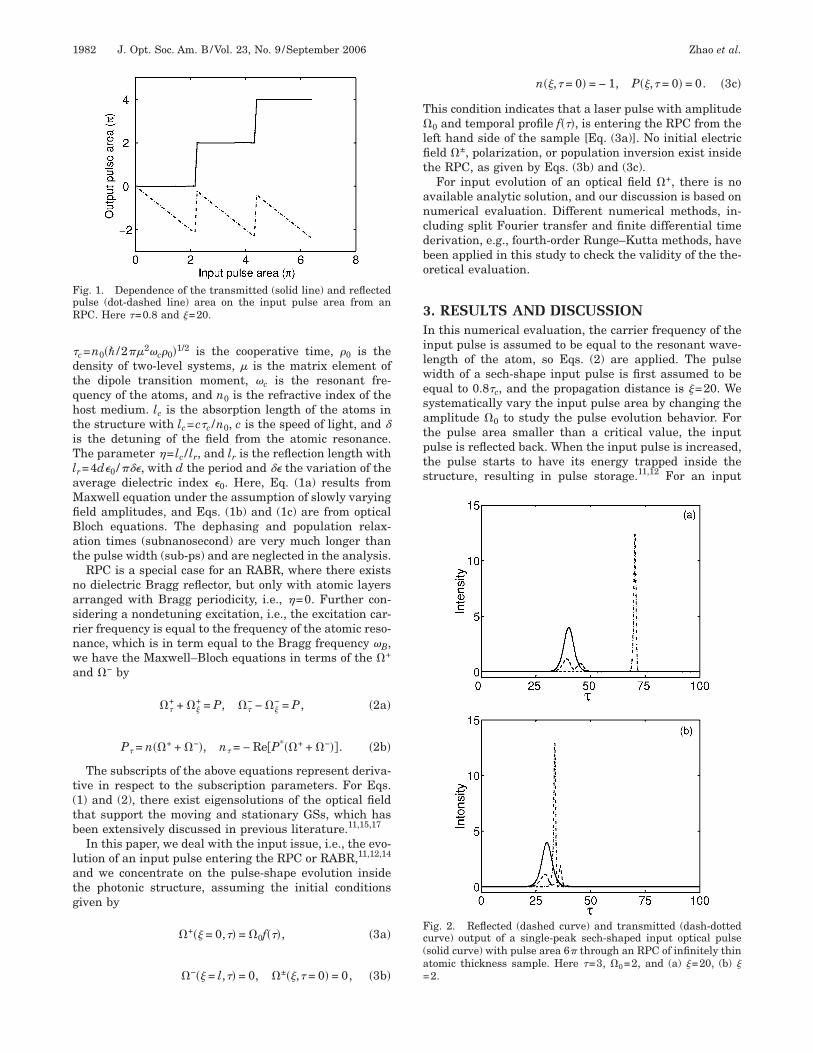
ig. 1. Dependence of the transmitted (solid line) and reflectedulse (dot-dashed line) area on the input pulse area from anPC. Here �=0.8 and �=20.
n��,� = 0� = − 1, P��,� = 0� = 0. �3c�
his condition indicates that a laser pulse with amplitude0 and temporal profile f���, is entering the RPC from the
eft hand side of the sample [Eq. (3a)]. No initial electriceld �±, polarization, or population inversion exist insidehe RPC, as given by Eqs. (3b) and (3c).
For input evolution of an optical field �+, there is novailable analytic solution, and our discussion is based onumerical evaluation. Different numerical methods, in-luding split Fourier transfer and finite differential timeerivation, e.g., fourth-order Runge–Kutta methods, haveeen applied in this study to check the validity of the the-retical evaluation.
. RESULTS AND DISCUSSIONn this numerical evaluation, the carrier frequency of thenput pulse is assumed to be equal to the resonant wave-ength of the atom, so Eqs. (2) are applied. The pulseidth of a sech-shape input pulse is first assumed to bequal to 0.8�c, and the propagation distance is �=20. Weystematically vary the input pulse area by changing themplitude �0 to study the pulse evolution behavior. Forhe pulse area smaller than a critical value, the inputulse is reflected back. When the input pulse is increased,he pulse starts to have its energy trapped inside thetructure, resulting in pulse storage.11,12 For an input
ig. 2. Reflected (dashed curve) and transmitted (dash-dottedurve) output of a single-peak sech-shaped input optical pulsesolid curve) with pulse area 6� through an RPC of infinitely thintomic thickness sample. Here �=3, �0=2, and (a) �=20, (b) �2.

pohpthvp
sshfpprarso
wpdpif2ltm
wpt3
ptb(
pinse
swpp−iptcs
sdintRFTirbpptpttFnb
ipr
FitafH
FtTT+e
Zhao et al. Vol. 23, No. 9 /September 2006 /J. Opt. Soc. Am. B 1983
ulse greater than a new critical value, a moving GS isbserved.16 The reflection, trapping, and transmission be-avior is shown in Fig. 1. The transmitted wave withulse area of 2n� (n is an integer) is a clear indicationhat the transmitting wave is a SIT pulse. On the otherand, the reflected pulse area may have any negativealue between 0 and 2�, resulting from its negative am-litude.The major difference of the SIT between the resonant
tructure and the SIT in bulk medium is that the formertructure reflects the input light pulse, whereas the latteras no reflection. An abrupt increase of the transmissionor increased input pulse area with RPC results in a su-ertransmission. This supertransmission transmits 2n�ulses by simultaneously blocking the excess energy byeflection. Notice that it does not require 2� input pulserea to produce a 2� transmitted wave, a result of multi-eflection inside the structure.15,16 Numerical resultshow that the required input pulse area to produce a 2�utput depends on the input pulse duration.
A typical single-peak sech-shape input pulse with pulseidth 3�c, and pulse area A=6� is shown to be com-ressed through the RPC in Fig. 2(a), with propagationistance �=20 and the intensity ���2. A ratio of pulse com-ression, measured with the pulse FWHM, by a factor of 6s obtained. Also, there is a distorted reflection outputrom the RPC, as described in Fig. 2(a). As shown in Fig.(b), this compression can be observed even with theength of the sample �=2 or L=2lc. Hence this transmit-ed pulse is a stable moving GS, as its pulse shape re-ains unchanged for increased RPC length.Study of the pulse shaping on different input pulse
idths with the same peak intensity shows that theulses are evolved to a special solution of the GS insidehe RPC for different input pulse width, as shown in Fig..The mechanism responsible for an almost-identical out-
ut waveform is interesting and is believed to be due tohe nature of the coherent emission, or radiation coupling,etween each of the atomic layers [or quantum wellsQWs)] of the RPC structure.18 It was demonstrated ex-
ig. 3. Dependence of the transmitted pulse for the sech-shapednput pulses of different pulse widths with the same intensityhrough the RPC. The input pulse widths are (a) 2, (b) 3, (c) 4,nd (d) 5 times �c. The dashed curves represent the input wave-orms, and the solid curves represent the output waveforms.ere �0=2 and �=20.
erimentally that the duration of the coherent emission isnversely proportional to the number n (n not a too largeumber) of multi-quantum-well (MQWs) structure (wellseparated by half of the exciton wavelength), which wasxplained in terms of interwell coupling.9,18
For a multiplepeak pulse input, the pulses can be re-haped to give rise to a single-peak output. The inputaveform is assumed as �+�t�=�+
1�t�+�+2�t�, i.e., a su-
erposition of two sech functions with identical initialhase. Here as an example, we use �+
1�t�=�0 sech��tt0� /3�c� and �+
2=0.7�0 sech��t− t0−10�c� /3�c�, indicat-ng that the two pulses have a delay of �t=10�c with aulsewidth of 3�c and t0=30�c. The �+ is chosen to have aotal input pulse area of 10.2�, so we have �0=2 in thisase. The pulse evolution of such a double-peak input ishown in Fig. 4.
It is clear that within a very short distance through theample, here ��2, the input field quickly evolves from aouble-peak waveform to a stable, single-peak moving GSnside the RPC, whereas the reflected wave presents aumber of satellite structures. The input, reflected, andransmitted temporal waveforms passing through thePC are shown in Fig. 5, with the electric field shown inig. 5(a) and their intensities, ���2, shown in Fig. 5(b).he results clearly show that the transmitted optical field
s reshaped to a shorter duration, more symmetric tempo-al waveform. The FWHM of the input pulse is shown toe compressed with the RPC from 26 to 2 for the outputulse, a 13-fold pulsewidth reduction, in contrast withulse compression in a one-dimensional conventional pho-onic crystal, where only a fraction of the pulsewidth com-ression was observed.19 Notice that the FWHM of theransmitted pulse is not only considerably shorter thanhe two-peak pulse, but also about one-sixth of theWHM of the individual input pulse. Nevertheless, a sig-ificant amount of the input pulse energy is reflectedack, as shown in Fig. 5(b).The finite thickness of each atomic layer is considered
n this work in order to numerically model the pulseropagation through a real experimental sample. Theo-etically, we follow the work of Kurizki et al.15 with a
ig. 4. Evolution of an input optical pulse with pulse area 10.2�hrough an RPC of an infinitely thin atomic thickness sample.he trace represents the population inversion inside the RPC.he input parameters are �+�t�=�0 sech��t− t0� /3�c�0.7�0 sech��t− t0−10�c� /3�c�, with �0=2, t0=10�c. Other param-ters are the same as in Fig. 3.

fswsfnsttscewtwba
ppi=−pdips
otdrsppcoblhsifpwra
pttttiptnp1
Rsppei
RBs
Ftsst
Fets
1984 J. Opt. Soc. Am. B/Vol. 23, No. 9 /September 2006 Zhao et al.
ourth-order Rugga–Kutta numerical analysis.20 For amall atomic thickness ��5 nm�, the input and outputaveforms remain similar to those of the �-thickness
ample. The pulse shaping in an RPC is very differentrom the ultrashort pulse storage, where the atomic thick-ess plays a critical role, which will have to be muchmaller than a critical value, which is about 1 nm.14 Inhe case of pulse shaping, the atomic thickness can be upo 7 nm without affecting the basic conclusion of pulsehaping. But for an atomic thickness greater than a criti-al value, for example, 9.6 nm, a great deal of pulse en-rgy will be trapped inside the RPC, as shown in Fig. 6,hich will be released from the structure at much later
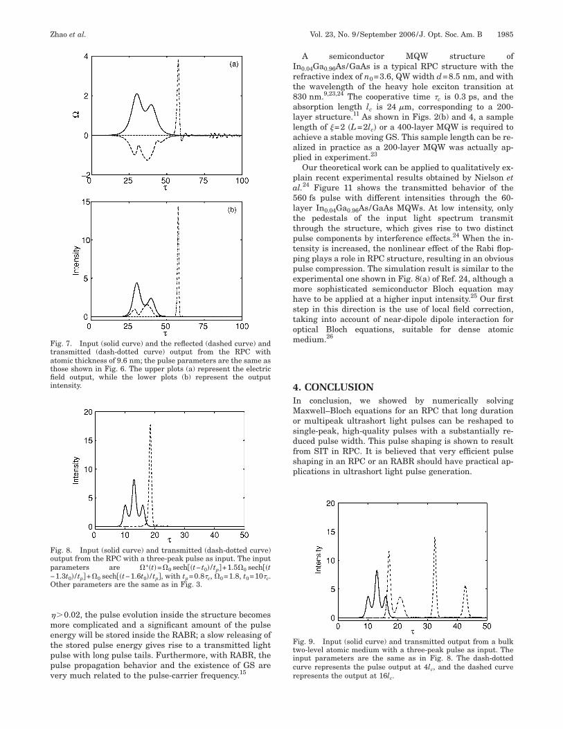
ime (not shown in Fig. 6). The transmitted and reflectedaves in the picosecond time window, however, retain theasic characters of the infinitely narrow thickness atomsnd are shown in Figs. 7(a) and 7(b).To show that the proposed technique can also be ap-
lied to a more general pulse shape, we carried out theulse propagation study by using a three-peak pulse asnput. The waveform of the pulse is given by �+�t��0 sech��t− t0� / tp�+1.5�0 sech��t−1.3t0� / tp�+�0 sech��t1.6t0� / tp�. Here t0 is the time of the first peak of the in-ut field and is assumed to be 10�c, tp=0.8�c is the pulseuration, and �0=1.8. With this input, single-peak outputs also obtained from the transmitted wave. The three-eak input and reflection and transmission output arehown in Fig. 8.
ig. 5. Input (solid curve) and the reflected (dashed curve) andransmitted (dash-dotted curve) output from the RPC with theame parameters as shown in Fig. 4. The upper plots (a) repre-ent the electric field output, while the lower plots (b) representhe output intensities.
Since SIT in bulk medium can be also used to shortenptical pulses,3–5,21 the propagation of the same ul-rashort light used for Figs. 6 and 7 through a bulk me-ium with atoms homogeneously doped inside is also car-ied out. In this case, the input pulse is split into twoeparate ultrashort light pulses, rather than a singleeak in the case of RPC, and the separations of the twoulses are further apart as the propagation distance in-reases, as shown in Fig. 9. It is possible to reduce the sec-nd transmitted peak by reducing the input pulse area,ut the required propagation distance (hence the sampleength) is very long before a stabilized pulse is formed in aomogeneously broadened two-level atomic system.22 Re-haping in an RPC is the result of the multiple reflectionsnside the medium, as shown in Figs. 5, 7, and 8, whereasor the bulk medium, no reflected wave exists, and theulse shaping is much less powerful. For pulse shapingith an RPC, a significant amount of the input pulses is
eflected back, facilitating a rapid pulse evolution towardshorter pulse duration, as shown in Figs. 2–8.The pulse-compression efficiency depends on the input
ulse shape and duration, and there is no analytic solu-ion to the efficiency for general pulse input. However, forhe pulse-shaping result shown in Fig. 6, the efficiency ofhe shaped transmitted energy to the input is 68%, andhe remaining pulse energy is reflected back or trappednside. Another issue of concern is how to extend shape in-ut waveforms to a single-peak output. The analytic solu-ion to this problem is not yet available, but the nonlinearature of the pulse transmission will result in an efficientulse shaping, even with the input form, as shown in Fig.0.We also consider an unsymmetrical input pulse into the
PC, and the effective pulse reshaping can also be ob-erved; the transmitted wave is in the form of a single-eak pulse. In principle, it is possible to carry out theulse-shaping study to a chirped input, but the numericalvaluation is more involved, as frequency detuning is var-ed during the pulse input.
Numerical evaluation for pulse propagation through anABR structure is carried out. For a weakly reflectingragg structure, i.e., ��0.01 in Eqs. (1), the basic conclu-ion for pulse shaping will not change. If � increases, e.g.,
ig. 6. Evolution of an input optical pulse, with pulse param-ters the same as those in Fig. 4, through an RPC with atomichickness of 9.6 nm. The trace represents the population inver-ion inside the RPC.
�metppv
Irt8allaap
pa5lttptppemhstom
4IMosdfsp
Ftatfii
Fop−O
Fticr
Zhao et al. Vol. 23, No. 9 /September 2006 /J. Opt. Soc. Am. B 1985
�0.02, the pulse evolution inside the structure becomesore complicated and a significant amount of the pulse
nergy will be stored inside the RABR; a slow releasing ofhe stored pulse energy gives rise to a transmitted lightulse with long pulse tails. Furthermore, with RABR, theulse propagation behavior and the existence of GS areery much related to the pulse-carrier frequency.15
ig. 7. Input (solid curve) and the reflected (dashed curve) andransmitted (dash-dotted curve) output from the RPC withtomic thickness of 9.6 nm; the pulse parameters are the same ashose shown in Fig. 6. The upper plots (a) represent the electriceld output, while the lower plots (b) represent the output
ntensity.
ig. 8. Input (solid curve) and transmitted (dash-dotted curve)utput from the RPC with a three-peak pulse as input. The inputarameters are �+�t�=�0 sech��t− t0� / tp�+1.5�0 sech��t1.3t0� / tp�+�0 sech��t−1.6t0� / tp�, with tp=0.8�c, �0=1.8, t0=10�c.ther parameters are the same as in Fig. 3.
A semiconductor MQW structure ofn0.04Ga0.96As/GaAs is a typical RPC structure with theefractive index of n0=3.6, QW width d=8.5 nm, and withhe wavelength of the heavy hole exciton transition at30 nm.9,23,24 The cooperative time �c is 0.3 ps, and thebsorption length lc is 24 m, corresponding to a 200-ayer structure.11 As shown in Figs. 2(b) and 4, a sampleength of �=2 �L=2lc� or a 400-layer MQW is required tochieve a stable moving GS. This sample length can be re-lized in practice as a 200-layer MQW was actually ap-lied in experiment.23
Our theoretical work can be applied to qualitatively ex-lain recent experimental results obtained by Nielson etl.24 Figure 11 shows the transmitted behavior of the60 fs pulse with different intensities through the 60-ayer In0.04Ga0.96As/GaAs MQWs. At low intensity, onlyhe pedestals of the input light spectrum transmithrough the structure, which gives rise to two distinctulse components by interference effects.24 When the in-ensity is increased, the nonlinear effect of the Rabi flop-ing plays a role in RPC structure, resulting in an obviousulse compression. The simulation result is similar to thexperimental one shown in Fig. 8(a) of Ref. 24, although aore sophisticated semiconductor Bloch equation mayave to be applied at a higher input intensity.25 Our firsttep in this direction is the use of local field correction,aking into account of near-dipole dipole interaction forptical Bloch equations, suitable for dense atomicedium.26
. CONCLUSIONn conclusion, we showed by numerically solvingaxwell–Bloch equations for an RPC that long duration
r multipeak ultrashort light pulses can be reshaped toingle-peak, high-quality pulses with a substantially re-uced pulse width. This pulse shaping is shown to resultrom SIT in RPC. It is believed that very efficient pulsehaping in an RPC or an RABR should have practical ap-lications in ultrashort light pulse generation.
ig. 9. Input (solid curve) and transmitted output from a bulkwo-level atomic medium with a three-peak pulse as input. Thenput parameters are the same as in Fig. 8. The dash-dottedurve represents the pulse output at 4lc, and the dashed curveepresents the output at 16l .
c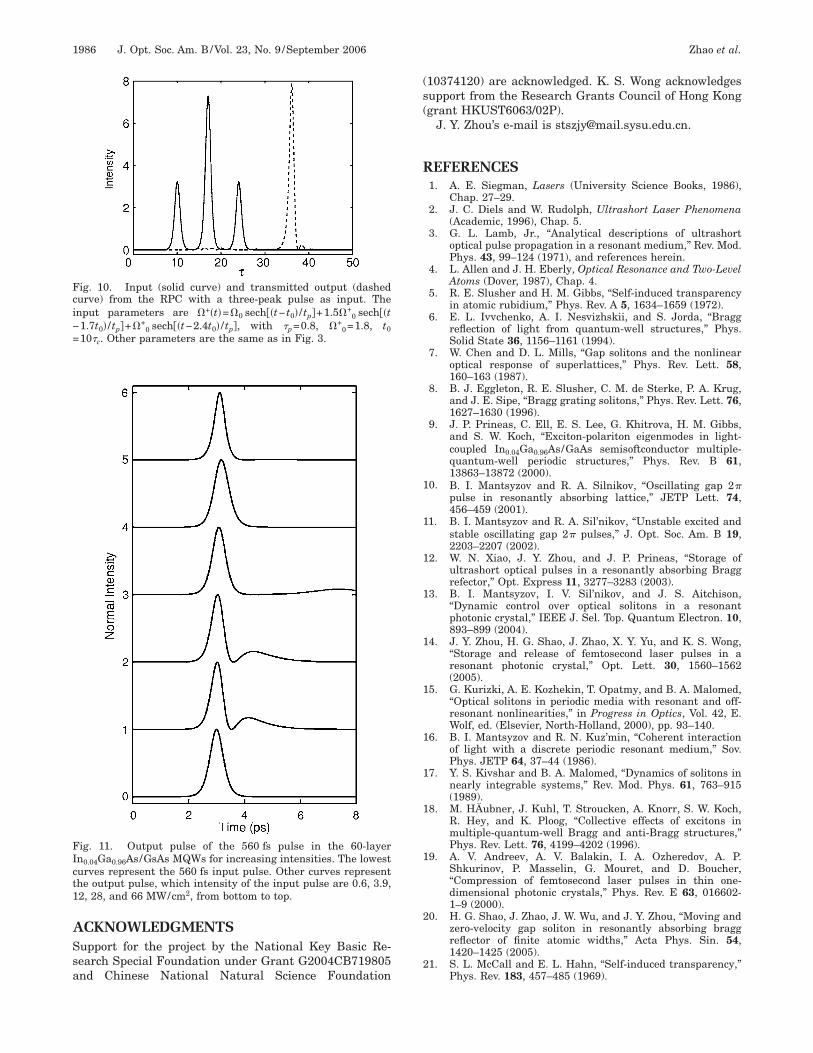
ASsa
(s(
R
1
1
1
1
1
1
1
1
1
1
2
2
Fci−=
FIct1
1986 J. Opt. Soc. Am. B/Vol. 23, No. 9 /September 2006 Zhao et al.
CKNOWLEDGMENTSupport for the project by the National Key Basic Re-earch Special Foundation under Grant G2004CB719805nd Chinese National Natural Science Foundation
ig. 10. Input (solid curve) and transmitted output (dashedurve) from the RPC with a three-peak pulse as input. Thenput parameters are �+�t�=�0 sech��t− t0� / tp�+1.5�+
0 sech��t1.7t0� / tp�+�+
0 sech��t−2.4t0� / tp�, with �p=0.8, �+0=1.8, t0
10�c. Other parameters are the same as in Fig. 3.
ig. 11. Output pulse of the 560 fs pulse in the 60-layern0.04Ga0.96As/GsAs MQWs for increasing intensities. The lowesturves represent the 560 fs input pulse. Other curves representhe output pulse, which intensity of the input pulse are 0.6, 3.9,2, 28, and 66 MW/cm2, from bottom to top.
10374120) are acknowledged. K. S. Wong acknowledgesupport from the Research Grants Council of Hong Konggrant HKUST6063/02P).
J. Y. Zhou’s e-mail is [email protected].
EFERENCES1. A. E. Siegman, Lasers (University Science Books, 1986),
Chap. 27–29.2. J. C. Diels and W. Rudolph, Ultrashort Laser Phenomena
(Academic, 1996), Chap. 5.3. G. L. Lamb, Jr., “Analytical descriptions of ultrashort
optical pulse propagation in a resonant medium,” Rev. Mod.Phys. 43, 99–124 (1971), and references herein.
4. L. Allen and J. H. Eberly, Optical Resonance and Two-LevelAtoms (Dover, 1987), Chap. 4.
5. R. E. Slusher and H. M. Gibbs, “Self-induced transparencyin atomic rubidium,” Phys. Rev. A 5, 1634–1659 (1972).
6. E. L. Ivvchenko, A. I. Nesvizhskii, and S. Jorda, “Braggreflection of light from quantum-well structures,” Phys.Solid State 36, 1156–1161 (1994).
7. W. Chen and D. L. Mills, “Gap solitons and the nonlinearoptical response of superlattices,” Phys. Rev. Lett. 58,160–163 (1987).
8. B. J. Eggleton, R. E. Slusher, C. M. de Sterke, P. A. Krug,and J. E. Sipe, “Bragg grating solitons,” Phys. Rev. Lett. 76,1627–1630 (1996).
9. J. P. Prineas, C. Ell, E. S. Lee, G. Khitrova, H. M. Gibbs,and S. W. Koch, “Exciton-polariton eigenmodes in light-coupled In0.04Ga0.96As/GaAs semisoftconductor multiple-quantum-well periodic structures,” Phys. Rev. B 61,13863–13872 (2000).
0. B. I. Mantsyzov and R. A. Silnikov, “Oscillating gap 2�pulse in resonantly absorbing lattice,” JETP Lett. 74,456–459 (2001).
1. B. I. Mantsyzov and R. A. Sil’nikov, “Unstable excited andstable oscillating gap 2� pulses,” J. Opt. Soc. Am. B 19,2203–2207 (2002).
2. W. N. Xiao, J. Y. Zhou, and J. P. Prineas, “Storage ofultrashort optical pulses in a resonantly absorbing Braggrefector,” Opt. Express 11, 3277–3283 (2003).
3. B. I. Mantsyzov, I. V. Sil’nikov, and J. S. Aitchison,“Dynamic control over optical solitons in a resonantphotonic crystal,” IEEE J. Sel. Top. Quantum Electron. 10,893–899 (2004).
4. J. Y. Zhou, H. G. Shao, J. Zhao, X. Y. Yu, and K. S. Wong,“Storage and release of femtosecond laser pulses in aresonant photonic crystal,” Opt. Lett. 30, 1560–1562(2005).
5. G. Kurizki, A. E. Kozhekin, T. Opatmy, and B. A. Malomed,“Optical solitons in periodic media with resonant and off-resonant nonlinearities,” in Progress in Optics, Vol. 42, E.Wolf, ed. (Elsevier, North-Holland, 2000), pp. 93–140.
6. B. I. Mantsyzov and R. N. Kuz’min, “Coherent interactionof light with a discrete periodic resonant medium,” Sov.Phys. JETP 64, 37–44 (1986).
7. Y. S. Kivshar and B. A. Malomed, “Dynamics of solitons innearly integrable systems,” Rev. Mod. Phys. 61, 763–915(1989).
8. M. HÄubner, J. Kuhl, T. Stroucken, A. Knorr, S. W. Koch,R. Hey, and K. Ploog, “Collective effects of excitons inmultiple-quantum-well Bragg and anti-Bragg structures,”Phys. Rev. Lett. 76, 4199–4202 (1996).
9. A. V. Andreev, A. V. Balakin, I. A. Ozheredov, A. P.Shkurinov, P. Masselin, G. Mouret, and D. Boucher,“Compression of femtosecond laser pulses in thin one-dimensional photonic crystals,” Phys. Rev. E 63, 016602-1–9 (2000).
0. H. G. Shao, J. Zhao, J. W. Wu, and J. Y. Zhou, “Moving andzero-velocity gap soliton in resonantly absorbing braggreflector of finite atomic widths,” Acta Phys. Sin. 54,1420–1425 (2005).
1. S. L. McCall and E. L. Hahn, “Self-induced transparency,”Phys. Rev. 183, 457–485 (1969).

2
2
2
2
2
Zhao et al. Vol. 23, No. 9 /September 2006 /J. Opt. Soc. Am. B 1987
2. N. Schupper, H. Friedmann, and M. Matusovsky,“Propagation of high-intensity short resonant pulses ininhomogeneously broadened media,” J. Opt. Soc. Am. B 16,1127–1134 (1999).
3. J. P. Prineas, J. Y. Zhou, J. Kuhl, H. M. Gibbs, G. Khitrova,S. W. Koch, and A. Knorr, “Ultrafast ac Stark effectswitching of the active photonic band gap from Bragg-periodic semiconductor quantum wells,” Appl. Phys. Lett.81, 4332–4334 (2002).
4. N. C. Nielsen, J. Kuhl, M. Schaarschmidt, J. Förstner, A.
Knorr, S. W. Koch, G. Khitova, H. M. Gibbs, and H.Giessen, “Linear and nonlinear pulse propagation in amultiple-quantum-well photonic crystal,” Phys. Rev. B 70,075306-1–10 (2004).
5. J. Shah, Ultrafast Spectroscopy of Semiconductor andSemiconductor Nanostructures (Springer-Verlag,1996).
6. J. Cheng and J. Y. Zhou, “Effects of the near-dipole–dipoleinteraction on gap solitons in resonantly absorbing
gratings,” Phys. Rev. E 66, 036606-1–5 (2002).