reservoir characteristics of belayim …ijseas.com/volume2/v2i1/ijseas20160156.pdf · well logging...
TRANSCRIPT

International Journal of Scientific Engineering and Applied Science (IJSEAS) – Volume-2, Issue-1, January 2016 ISSN: 2395-3470
www.ijseas.com
435
RESERVOIR CHARACTERISTICS OF BELAYIM FORMATION IN BELAYIM LAND OIL FIELD, SOUTHWEST SINAI, EGYPT, USING CORE AND WELL
LOGGING ANALYSIS
By
El-Khadragy,A. AP
(1)P; Eysa, E. AP
(1)P; Khedr,F. IP
(2)P; Saleh, A. H.P
(1)
Geology Department, Faculty of sciences, Zagazig University.)1(
(2) Geology Department, Faculty of sciences, Suez Canal University.
ABSTRACT In the present study, core analysis data in Belayim land oil field had been used to evaluate
the characteristics of clastics of Belayim Formation. Special core analysis of 116 core samples of Belayim clastics in well BELL BAY#4 (BB#4) was done by corex services and studied in the form of formation resistivity (formation resistivity factor, formation resistivity index), capillary pressure tests and pore size distribution.
Well logging data of 5 wells (113-26, 112-46, BELL BAY # 4, 112-82, 113-81) were used to evaluate the reservoir parameters. This study was done utilizing different types of open-hole well logs; for the determination of the included petrophysical parameters. Several methods were used to determine the shale content depending on the available logs, where the shale volume is important for the correction of the porosity and water saturation values from the effect of shaliness. The porosities were determined using the available porosity tools such as sonic, density and neutron. These porosities were corrected for the effect of shaliness, and then were discriminated into total and effective porosities. The water saturation models were chosen according to the prevailed shale model .For the clean rocks, Archie's formula was used to calculate the water saturation, while Simandoux equation was used for the shaly formation .These reservoir parameters of Belayim clastics are mapped to show the aerial distribution of these parameters. Interpretation of these maps showed that the best locations of hydrocarbon accumulation in Belayim land oil field are at northwest direction and in the middle part of the area. The petrophysical results were presented in the form of petrophysical data logs for the studied wells, exhibiting the vertical variation of these parameters, zone-wise. Keywords: Belayim, Sinai, Reservoir characteristics
1. INTRODUCTION
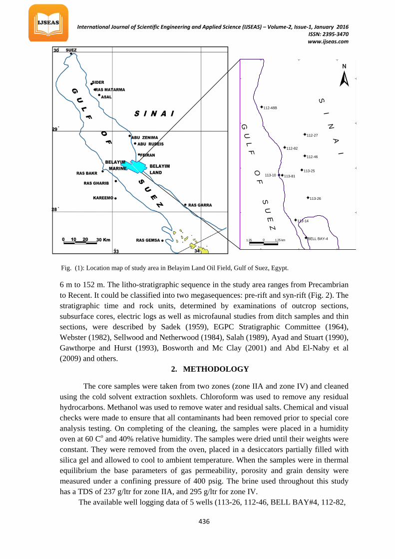
Be1ayim land oil field lies on the eastern side of the Gulf of Suez, one hundred and sixty five kilometers southeast of the Suez City (Fig. 1). Belayim Formation was deposited in NW-SE trending low areas. It is not deposited at the extreme northern part of the gulf (Meshref et al., 1988). It represents the beginning of the main Miocene evaporitic cycle. It ranges in thickness from 53 m to 427 m and was deposited in a lagoonal to shallow marine setting. It is subdivided into four members from base to top; Baba, Sidri, Feiran and Hammam Faraun. (1) Baba Member: It comprises mainly of anhydrite with subordinates shale. (2) Sidri Member: It consists mainly of shale with thin streaks of limestone and/or sandstone. (3) Feiran Member: It is mainly composed of halite with anhydrite and thin shale interbeds. The thickness of this member ranges between 27 m and 174 m. Generally, it increases in thickness southward due to salt withdrawal. (4) Hammam Faraun Member: It consists of shale with sand and/or limestone or dolomite interbeds. The sand ratio increases toward the basinal margins. It ranges in thickness from
International Journal of Scientific Engineering and Applied Science (IJSEAS) – Volume-2, Issue-1, January 2016 ISSN: 2395-3470
www.ijseas.com
436
6 m to 152 m. The litho-stratigraphic sequence in the study area ranges from Precambrian to Recent. It could be classified into two megasequences: pre-rift and syn-rift (Fig. 2). The stratigraphic time and rock units, determined by examinations of outcrop sections, subsurface cores, electric logs as well as microfaunal studies from ditch samples and thin sections, were described by Sadek (1959), EGPC Stratigraphic Committee (1964), Webster (1982), Sellwood and Netherwood (1984), Salah (1989), Ayad and Stuart (1990), Gawthorpe and Hurst (1993), Bosworth and Mc Clay (2001) and Abd El-Naby et al (2009) and others.
2. METHODOLOGY
The core samples were taken from two zones (zone IIA and zone IV) and cleaned using the cold solvent extraction soxhlets. Chloroform was used to remove any residual hydrocarbons. Methanol was used to remove water and residual salts. Chemical and visual checks were made to ensure that all contaminants had been removed prior to special core analysis testing. On completing of the cleaning, the samples were placed in a humidity oven at 60R RCP
oP and 40% relative humidity. The samples were dried until their weights were
constant. They were removed from the oven, placed in a desiccators partially filled with silica gel and allowed to cool to ambient temperature. When the samples were in thermal equilibrium the base parameters of gas permeability, porosity and grain density were measured under a confining pressure of 400 psig. The brine used throughout this study has a TDS of 237 g/ltr for zone IIA, and 295 g/ltr for zone IV.
The available well logging data of 5 wells (113-26, 112-46, BELL BAY#4, 112-82,
BELL BAY-4
113-14
113-26
113-81113-25
112-46
112-82
112-27
112-48B
113-10
1.25 km01.25 km
2841'
2839'
2837'
2835'
33 633 33
G U
L F O F S U
E Z
S I N A I
Fig. (1): Location map of study area in Belayim Land Oil Field, Gulf of Suez, Egypt.

International Journal of Scientific Engineering and Applied Science (IJSEAS) – Volume-2, Issue-1, January 2016 ISSN: 2395-3470
www.ijseas.com
437
113-81) are digitized using scanner and Grapher 7 program. After digitizing all logs, the data processing of well logs is performed on all well logs including data base editing and data correction. Data base editing means confirming the digitized well log data with the original curves to be identical. Flagging the missing and bad data and reconstruct it. Depth alignment of all logs is done in the same well. Environmental corrections were applied for the gamma ray, density, neutron and resistivity logs in the studied wells. The corrected data of well logs were used to evaluate the reservoir parameters of Belayim Formation using LOGWIZARD software. The reservoir parameters include gross thickness, net pay thickness, total porosity, effective porosity, shale volume, water saturation, bulk pore volume and oil in place indicator. The bulk pore volume (PHIH) can be calculated using the equation PHIH = (PHI* integrated net pay) while the oil in place indicator (HPVH) is calculated using these equation HPVH = (integrated PHIH * (1-Sw)). On the other hand, the net pay thickness is calculated using 10% or more for effective porosity, 35% or less for shale volume and 50% or less for water saturation.
3. RESULT AND DISCUSSION A) CORE ANALYSIS
1. Special core analysis 1.1 Relationship between porosity and formation resistivity factor
The general equation relating formation factor with porosity is given below:
LithologyFormation Oil
Zeit
SouthGharib
Belayim
Kareem
Rudeis
Nukhul
Abu Zabal
Minia
ThebesEsna Shale
Matulla
Wata
Galala
Qiseib
AheimerBlack Shale
Granites and GneissesSandstone
Shale and sandstone
Sandstone and shale
Sand and Lime stone
Sandstone, marl and limestone
Sandstone, marl and imestone
Upper ?
MiddleM
ioce
ne
Oligocene
Eocene
Paleocene
Cretaceous
JurassicPermo Triassic
Carboniferous
Pre CarboniferousPre Cambrian
Lower
Lower
Middle
Senonian
Turonian
Cenomanian
UpperLower
Geologic age Description Averagethick. (m)
510
Alpine 40
975
1030
Laramide60
?
??
330702095
50
120
15050
Hercynian
240
Limestone, dolomite and marl
ChalkShale and marl
Limestone with marl
Limestone with some marl and shales
Basalt (in northern area)
Basal conglomerate and sandstone
Globigerina marls and shales with sandstone
Evaporites
Evaporites with some shales and sandstone
Limestone
Gravel, sand, marl and shalePliocene Pleistocene
Fig. (2): Generalized Litho-Stratigraphy of the Gulf of Suez (after Barakat, 1982).

International Journal of Scientific Engineering and Applied Science (IJSEAS) – Volume-2, Issue-1, January 2016 ISSN: 2395-3470
www.ijseas.com
438
(a) (b)
maF −= φ. Where; a = Tortuosity & m = Cementation factor.
The current conductance represented by the fractional porosity (Calhoun, 1960).
The relationship of the Belayim samples porosity versus formation factor at different conditions (at room condition and at overburden pressure of 6100 psig) have been illustrated in Figure 3 (a & b) respectively.
1.2 Relationship between resistivity index and water saturation The interpretation of these logs is based on two empirical equations given by
Archie (1942). They are as follows: 𝐼 = 𝑅𝑡
𝑅0 = 1
𝑆𝑊𝑛 & F = R0RW
= 1фm
Where: I = Resistivity Index, RRtR = Rock resistivity at partial Brine Saturation, n = Saturation Exponent, RR0R = Rock resistivity at 100% Brine Saturation, F = Formation Factor, RRwR=Brine Resistivity, m = Cementation factor.
These equations were originally proposed for clean sands but were subsequently used by many authors to account for the presence of conductive clays (e.g. Shaly sands). The general equation which represent the relationship between resistivity index (I) and water saturation (SRwR): (I = c SRw RP
-nP) is used. Figure (4) represents the relationship between
resistivity index (I) and water saturation (SRwR) of Belayim samples which is negative relationship with high correlation coefficient (R = -0.97) and regression equation (I = 0.96 SRwRP
-2.05P). The constant(c = 0.96) and the saturation exponent (n = 2.05) of Belayim samples
reflect the water wet phenomenon. The different reservoir parameters as tortuosity (a),
y = 1.741x-1.28 R= -0.99
1
10
100
0.01 0.10 1.00
Form
atio
n fa
ctor
Porosity, fraction
y = 1.395x-1.55 R = -0.99
1
10
100
1000
0.01 0.10 1.00
Form
atio
n fa
ctor
Porosity, fraction
y = 0.955x-2.05 R = -0.97
1
10
100
0.1 1
Resi
stiv
ity In
dex
Water saturation,fraction
Fig. (3): Relationship between porosity and formation resistivity factor for Belayim Formation in BB#4 well, Belayim land oil field, Gulf of Suez, Egypt.
Fig. (4): Relationship between water saturation and resistivity index for Belayim Formation samples in BB#4 well, Belayim land oil field, Gulf of Suez, Egypt.
At overburden pressure of 6100 psig
At room condition
International Journal of Scientific Engineering and Applied Science (IJSEAS) – Volume-2, Issue-1, January 2016 ISSN: 2395-3470
www.ijseas.com
439
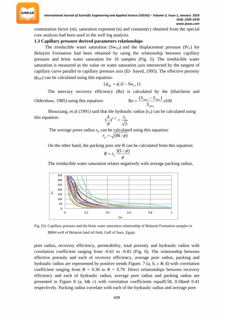
cementation factor (m), saturation exponent (n) and constant(c) obtained from the special core analysis had been used in the well log analysis. 1.3 Capillary pressure derived parameters relationships
The irreducible water saturation (SwRirrR) and the displacement pressure (PcRiR) for Belayim Formation had been obtained by using the relationship between capillary pressure and brine water saturation for 16 samples (Fig. 5). The irreducible water saturation is measured as the value on water saturation axis intersected by the tangent of capillary curve parallel to capillary pressure axis (El- Sayed, 1995). The effective porosity (φReffR) can be calculated using this equation:
( )1( irrteff Sw−= φφ )
The mercury recovery efficiency (Re) is calculated by the (Hutcheon and
Oldershaw, 1985) using this equation:
100)(
Remax
minmax xS
SS −=
Shouxiang, et al (1991) said that the hydraulic radius (rRhR) can be calculated using this equation:
The average pores radius rRpR can be calculated using this equation:
On the other hand, the packing pore site R can be calculated from this equation:
The irreducible water saturation relates negatively with average packing radius,
Fig. (5): Capillary pressure and the brine water saturation relationship of Belayim Formation samples in
BB#4 well of Belayim land oil field, Gulf of Suez, Egypt.
pore radius, recovery efficiency, permeability, total porosity and hydraulic radius with correlation coefficient ranging from -0.61 to -0.82 (Fig. 6). The relationship between effective porosity and each of recovery efficiency, average pore radius, packing and hydraulic radius are represented by positive trends Figure. 7 (a, b, c & d) with correlation coefficient ranging from R = 0.36 to R = 0.79. Direct relationships between recovery efficiency and each of hydraulic radius, average pore radius and packing radius are presented in Figure 8 (a, b& c) with correlation coefficients equal0.58, 0.58and 0.41 respectively. Packing radius correlate with each of the hydraulic radius and average pore
050
100150200250300350
0 0.2 0.4 0.6 0.8 1
Pc
Sw
5)( 2/1 hrk
=φ
)/8( φkrp =
φφ)1(3 −
= hrR

International Journal of Scientific Engineering and Applied Science (IJSEAS) – Volume-2, Issue-1, January 2016 ISSN: 2395-3470
www.ijseas.com
440
Fig. (7): Relationship between effective porosity and different capillary pressure derived parameters of
Belayim Formation samples in BB#4 well of Belayim land oil field, Gulf of Suez, Egypt.
radiuses in Figure 8(d & e) with correlation coefficient 0.90 for each of them .The linear regression equations correlation coefficients of all relations are shown on the figures.
(b) (a)
(f) (e)
(d) (c)
(b) (a)
y = -2598x + 924.1 R = - 0.61
0
500
1000
1500
0 0.1 0.2 0.3 0.4
Pack
ing
Irreducible water saturation, fraction
y = -376.2x + 98.47 R = - 0.70
0
50
100
150
0 0.1 0.2 0.3 0.4
Hyd
ralic
radi
us
Irreducible water saturation, fraction
y = 1156e-24.5x R = - 0.82
0.1
1
10
100
1000
0 0.1 0.2 0.3 0.4Perm
eabi
lity,
md
Irreducible water saturation, fraction
y = -0.669x + 0.277 R = - 0.69
0
0.1
0.2
0.3
0 0.1 0.2 0.3 0.4
Tota
l por
osity
, fr
actio
n
Irreducible water saturation, fraction
y = -475.9x + 124.5 R = - 0.70
0
50
100
150
200
0 0.1 0.2 0.3 0.4
Pore
radi
us
Irreducible water saturation, fraction
y = -29.81x + 100.0 R =- 0.67
80859095
100
0 0.1 0.2 0.3 0.4
Reco
very
ef
feci
ency
,%
Irreducible water saturation, fraction
y = 46.14x + 88.25 R = 0.79
80
85
90
95
100
0 0.1 0.2 0.3
Reco
very
ef
feci
ency
,%
Effective porosity, fraction
y = 502.3x - 23.48 R = 0.69
0
50
100
150
200
0 0.1 0.2 0.3Pore
radi
us
Effective porosity, fraction
y = 1641.x + 287.2 R = 0.36
0
500
1000
1500
0 0.1 0.2 0.3
Pack
ing
Effective porosity, fraction
y = 397.1x - 18.56 R = 0.69
0
50
100
150
0 0.1 0.2 0.3Hyd
ralic
radi
us
Effective porosity, fraction
(c) (d)
Fig. (6): Relationship between irreducible water saturation and different capillary pressure derived parameters of
Belayim Formation in BB#4 well of Belayim land oil field, Gulf of Suez, Egypt.

International Journal of Scientific Engineering and Applied Science (IJSEAS) – Volume-2, Issue-1, January 2016 ISSN: 2395-3470
www.ijseas.com
441
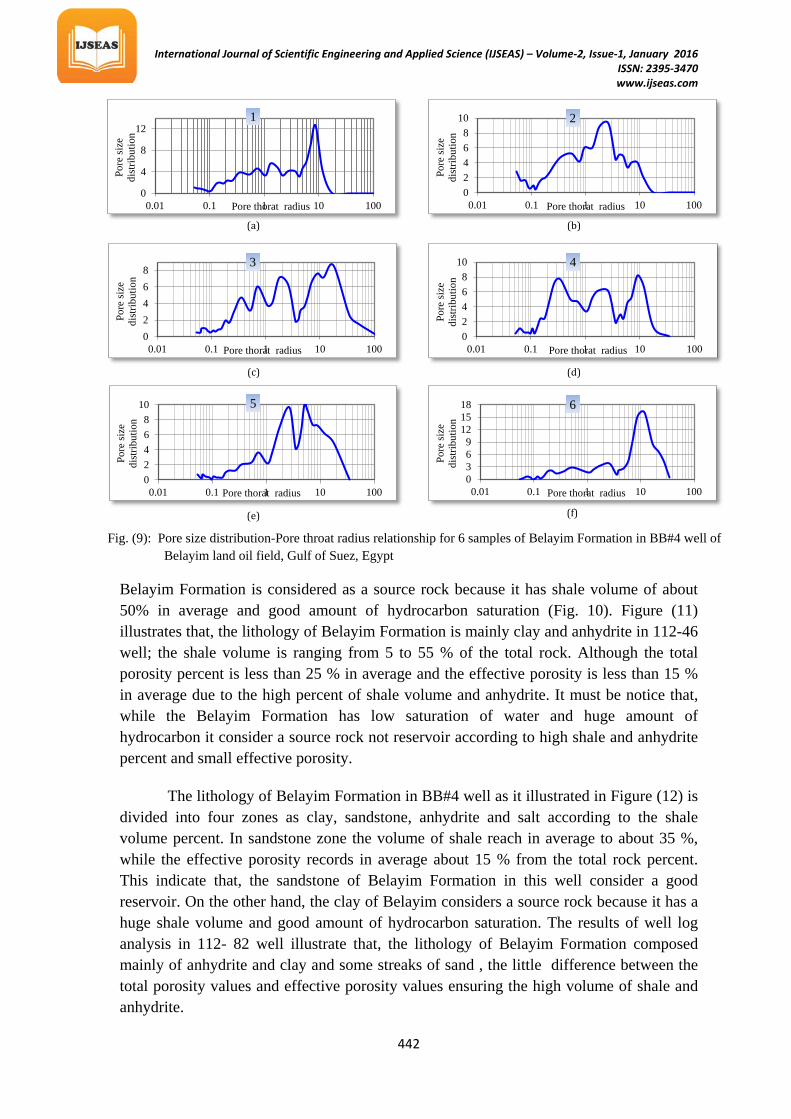
1.4 Pore size distribution-Pore throat radius relationship
The Pore size distribution is an important parameter for analysis of many fluids transport properties of porous media, (Obeida, 1988). Pore size distribution for 6 samples were measured at different pore throat radius values about (33 value) they are ranging (0.053flm) to (106.662 flm). The mean pore throats for the six samples range from 2 flm to 40 flm (Fig. 9).
B) Well log analysis 1. Input Data and Interpreted Results
The redrawing of the raw and result data gives true picture of the vertical distribution of the lithology and its conclusion and their physical effect on the different logs .This were drawn by using the Microsoft excel and surfer programs to collect all data in one figure for every well and plotting lithology versus the depth of well for Belayim Formation. The input data and the output results were drawn in one figure for every well. The input data contains (gamma ray, density, neutron, deep resistivity, shallow resistivity, sonic logs and the lithology). The results of the input data analysis contain (shale volume, total porosity, effective porosity, water saturation, hydrocarbon saturation). Belayim Formation in 113-26 well can be divided into three rock units according to the main lithologies which are sandstone, shale and salt zones. The effective porosity in the sandstone zones reach to about 24 % and the shale volume is less than 20 % of the total rock. The hydrocarbon saturation ranges from 40 % to 80 %. This indicates that Belayim Formation in this well is good reservoir in the sandstone zones. On the other hand, clay of
(d)
(e)
(c)
(b) (a)
y = 0.113x - 18.48 R = 0.90
0
50
100
150
0 500 1000 1500
Hyd
ralic
radi
us
Packing
y = 0.143x - 23.37 R = 0.90
050
100150200
0 500 1000 1500
pore
radi
us
Packing
y = 31.80x - 2492. R = 0.41
0
500
1000
1500
80 85 90 95 100
Pack
ing
Recovery effeciency,%
Fig. (8): Relationship between different capillary
pressure parameters of Belayim Formation
samples in BB#4 well of Belayim land oil
field, Gulf of Suez, Egypt.
y = 5.672x - 498.1 R = 0.58
0
50
100
150
80 85 90 95 100
Hyd
ralic
radi
us
Recovery effeciency,%
y = 7.175x - 630.0 R = 0.58
0
50
100
150
200
80 85 90 95 100
Pore
radi
us
Recovery effeciency,%
International Journal of Scientific Engineering and Applied Science (IJSEAS) – Volume-2, Issue-1, January 2016 ISSN: 2395-3470
www.ijseas.com
442
(f) (e)
(d) (c)
(b) (a)
0
4
8
12
0.01 0.1 1 10 100
Pore
size
di
strib
utio
n
Pore thorat radius
1
02468
10
0.01 0.1 1 10 100
Pore
size
di
strib
utio
n
Pore thorat radius
2
02468
0.01 0.1 1 10 100
Pore
size
di
strib
utio
n
Pore thorat radius
3
02468
10
0.01 0.1 1 10 100
Pore
size
di
strib
utio
n
Pore thorat radius
4
0369
121518
0.01 0.1 1 10 100
Pore
size
di
strib
utio
n
Pore thorat radius
6
02468
10
0.01 0.1 1 10 100
Pore
size
di
strib
utio
n
Pore thorat radius
5
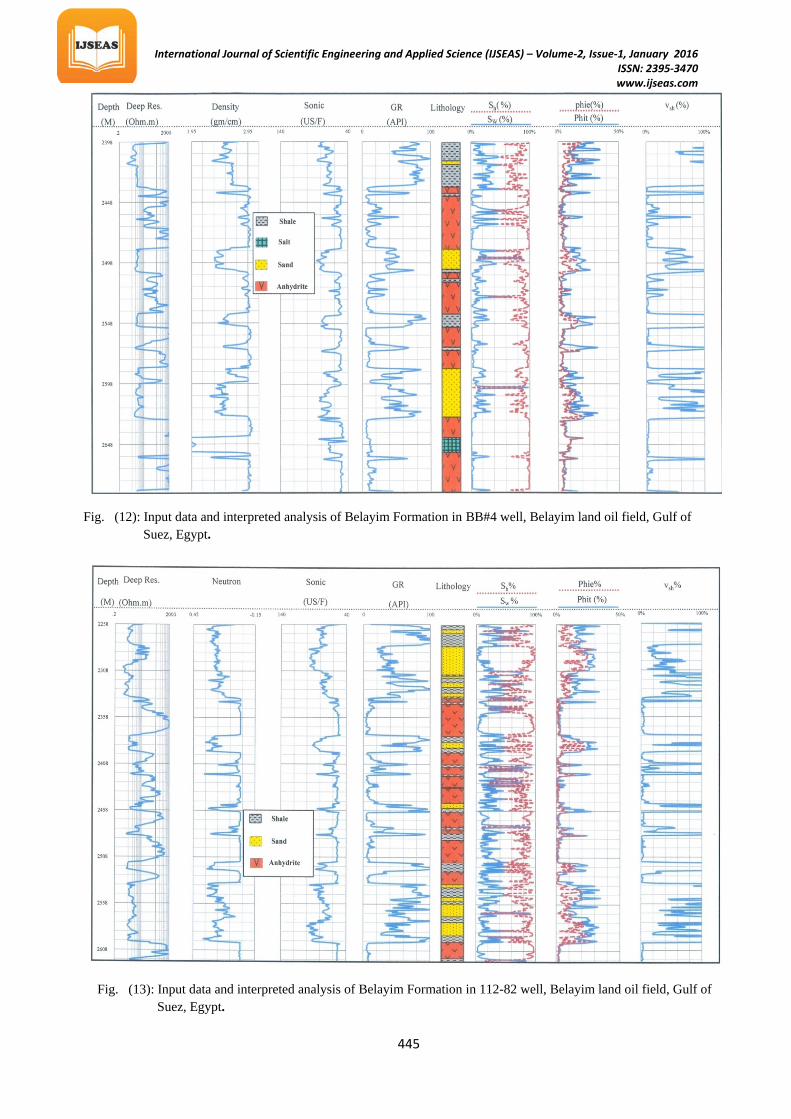
Belayim Formation is considered as a source rock because it has shale volume of about 50% in average and good amount of hydrocarbon saturation (Fig. 10). Figure (11) illustrates that, the lithology of Belayim Formation is mainly clay and anhydrite in 112-46 well; the shale volume is ranging from 5 to 55 % of the total rock. Although the total porosity percent is less than 25 % in average and the effective porosity is less than 15 % in average due to the high percent of shale volume and anhydrite. It must be notice that, while the Belayim Formation has low saturation of water and huge amount of hydrocarbon it consider a source rock not reservoir according to high shale and anhydrite percent and small effective porosity.
The lithology of Belayim Formation in BB#4 well as it illustrated in Figure (12) is divided into four zones as clay, sandstone, anhydrite and salt according to the shale volume percent. In sandstone zone the volume of shale reach in average to about 35 %, while the effective porosity records in average about 15 % from the total rock percent. This indicate that, the sandstone of Belayim Formation in this well consider a good reservoir. On the other hand, the clay of Belayim considers a source rock because it has a huge shale volume and good amount of hydrocarbon saturation. The results of well log analysis in 112- 82 well illustrate that, the lithology of Belayim Formation composed mainly of anhydrite and clay and some streaks of sand , the little difference between the total porosity values and effective porosity values ensuring the high volume of shale and anhydrite.
Fig. (9): Pore size distribution-Pore throat radius relationship for 6 samples of Belayim Formation in BB#4 well of Belayim land oil field, Gulf of Suez, Egypt

International Journal of Scientific Engineering and Applied Science (IJSEAS) – Volume-2, Issue-1, January 2016 ISSN: 2395-3470
www.ijseas.com
443
Fig. (10): Input data and interpreted analysis of Belayim Formation in113-26 well, Belayim land oil field, Gulf of Suez, Egypt.
Fig. (11): Input data and interpreted analysis of Belayim Formation in112-46 well, Belayim land oil field, Gulf of Suez, Egypt.

International Journal of Scientific Engineering and Applied Science (IJSEAS) – Volume-2, Issue-1, January 2016 ISSN: 2395-3470
www.ijseas.com
444
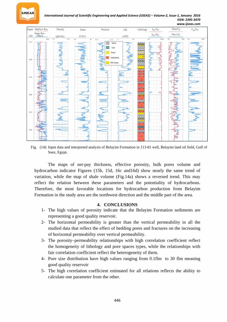
The water saturation percent in this Formation is very low while the saturation percent is very high with high volume of shale. This indicates that, this Formation is hydrocarbon source as it is illustrated from (Fig. 13). The lithology of Belayim Formation in 113-81 well is illustrated in Figure (14). It can be divided to four rock units as clay, sandstone, anhydrite and salt. The shale volume records in average about 80 % in the clay rocks while, it reach about 17 % in average in the sandstone rocks. The effective porosity reach about 7 % in the clay zone while it record about 22 % in the sandstone, thus it can be say that, the clay of Belayim Formation consider a source rock while the Belayim sandstone consider a very good reservoir. It has a high hydrocarbon percent of the fluid content.
2. Reservoir mapping
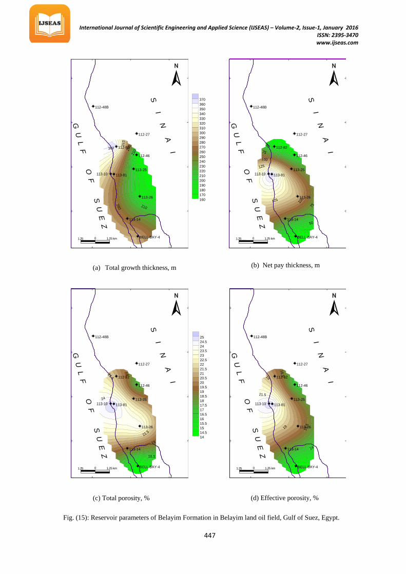
Well log furnish the data necessary for quantitative evaluation of hydrocarbon. Modern logs provide valuable information on both rock and fluid properties of the penetrated formation, and its costs account for only about 2% to 5% of completed well costs, so it is false economy to cut corners in this phase (Desbrandes, 1968 and Dewan, 1983). The results of well log analysis are contoured for constructing eight iso-parametric maps to illustrate the lateral distribution of these petrophysical parameters (Figs.15&16). The total growth thickness, net-pay thickness, total porosity, effective porosity, shale content, water saturation, bulk pore volume, hydrocarbon indicator maps had been interpreted .
The total growth thickness increases in the southwest, northwest and west directions, and decreases toward the East. The maximum thickness is 362m in well 112-82, and the minimum thickness is 171 m in 112- 46 well (Fig. 15a). The net-pay thickness (Fig.15b) increases toward the west and decreases gradually toward the southeast, south, northeast and north direction. The minimum net-pay thickness (26 m) is recorded at BELL bay#4 well, while the maximum net-pay thickness (166 m) occurs at 113-81 well. The total porosity (Fig.15c) increases in the northwest direction, and decreases toward the northeast and south directions. The maximum value is 25% in 113-81, and the minimum value is 14% at BELLbay#4 well. The effective porosity (Fig.15d) increases in the northwest direction, and decreases toward the east, northeast and south directions. The maximum value is 23% in 113-81, and the minimum value is 12% at BELLbay#4 well. The shale content (Fig.16a) increases toward the northwest and south, decreases toward the east, northeast and the middle of the area .the maximum value is 81% at 112-82, and the minimum value is 18% in 112-46 well.
The water saturation (Fig.16b) increases toward southeast and decreases toward the north, northeast and southwest, the maximum value is 19% at 113-26, and the minimum value is 2% at 113-81 well. The bulk volume of pores (Fig.16c) increases toward the northwest. It decreases toward the northeast and southeast direction. The maximum value is 27.70 at 112-82, and the minimum value is 7.06 in 112-46 well. The hydrocarbon indicator (Fig.16d) increases toward the northwest, and decreases toward the northeast, southeast and east directions. The maximum value is 25.86 at 112-82, and the minimum value is 6.63 at 112-46 well.
International Journal of Scientific Engineering and Applied Science (IJSEAS) – Volume-2, Issue-1, January 2016 ISSN: 2395-3470
www.ijseas.com
445
Fig. (13): Input data and interpreted analysis of Belayim Formation in 112-82 well, Belayim land oil field, Gulf of Suez, Egypt.
Fig. (12): Input data and interpreted analysis of Belayim Formation in BB#4 well, Belayim land oil field, Gulf of Suez, Egypt.
International Journal of Scientific Engineering and Applied Science (IJSEAS) – Volume-2, Issue-1, January 2016 ISSN: 2395-3470
www.ijseas.com
446
The maps of net-pay thickness, effective porosity, bulk pores volume and hydrocarbon indicator Figures (15b, 15d, 16c and16d) show nearly the same trend of variation, while the map of shale volume (Fig.14a) shows a reversed trend. This may reflect the relation between these parameters and the potentiality of hydrocarbons. Therefore, the most favorable locations for hydrocarbon production from Belayim Formation in the study area are the northwest direction and the middle part of the area.
4. CONCLUSIONS 1- The high values of porosity indicate that the Belayim Formation sediments are
representing a good quality reservoir. 2- The horizontal permeability is greater than the vertical permeability in all the
studied data that reflect the effect of bedding pores and fractures on the increasing of horizontal permeability over vertical permeability.
3- The porosity–permeability relationships with high correlation coefficient reflect the homogeneity of lithology and pore spaces types, while the relationships with fair correlation coefficient reflect the heterogeneity of them.
4- Pore size distribution have high values ranging from 0.1flm to 30 flm meaning good quality reservoir
5- The high correlation coefficient estimated for all relations reflects the ability to calculate one parameter from the other.
Fig. (14): Input data and interpreted analysis of Belayim Formation in 113-81 well, Belayim land oil field, Gulf of Suez, Egypt.
International Journal of Scientific Engineering and Applied Science (IJSEAS) – Volume-2, Issue-1, January 2016 ISSN: 2395-3470
www.ijseas.com
447
160170180190200210220230240250260270280290300310320330340350360370
210
210
260
260
310
360
BELL BAY-4
113-14
113-26
113-81113-25
112-46
112-82
112-27
112-48B
113-10
1.25 km01.25 km
2841'
2839'
2837'
2835'
33 633 33
G U
L F O F S U
E Z
S I N A I
50
50
75
75
100
100
125
125
BELL BAY-4
113-14
113-26
113-81113-25
112-46
112-82
112-27
112-48B
113-10
1.25 km01.25 km
2841'
2839'
2837'
2835'
33 633 33
G U
L F O F S U
E Z
S I N A I
1414.51515.51616.51717.51818.51919.52020.52121.52222.52323.52424.525
16.5
19
1921.5
21.5
24
BELL BAY-4
113-14
113-26
113-81113-25
112-46
112-82
112-27
112-48B
113-10
1.25 km01.25 km
2841'
2839'
2837'
2835'
33 633 33
G U
L F O F S U
E Z
S I N A I
14
16.5
16.5
19
19
21.5
BELL BAY-4
113-14
113-26
113-81113-25
112-46
112-82
112-27
112-48B
113-10
1.25 km01.25 km
2841'
2839'
2837'
2835'
33 633 33
G U
L F O F S U
E Z
S I N A I
Fig. (15): Reservoir parameters of Belayim Formation in Belayim land oil field, Gulf of Suez, Egypt.
(c) Total porosity, %
(a) Total growth thickness, m (b) Net pay thickness, m
(d) Effective porosity, %

International Journal of Scientific Engineering and Applied Science (IJSEAS) – Volume-2, Issue-1, January 2016 ISSN: 2395-3470
www.ijseas.com
448
30
30
45
45
60
75
BELL BAY-4
113-14
113-26
113-81113-25
112-46
112-82
112-27
112-48B
113-10
1.25 km01.25 km
2841'
2839'
2837'
2835'
33 633 33
G U
L F O F S U
E Z
S I N A I
2345678910111213141516171819
7
7
7
12
12
BELL BAY-4
113-14
113-26
113-81113-25
112-46
112-82
112-27
112-48B
113-10
1.25 km01.25 km
2841'
2839'
2837'
2835'
33 633 33
G U
L F O F S U
E Z
S I N A I
7891011121314151617181920212223242526272829
1217
17
22
22
27
BELL BAY-4
113-14
113-26
113-81113-25
112-46
112-82
112-27
112-48B
113-10
1.25 km01.25 km
2841'
2839'
2837'
2835'
33 633 33
G U
L F O F S U
E Z
S I N A I
678910111213141516171819202122232425262728
1116
16
21
21
26
BELL BAY-4
113-14
113-26
113-81113-25
112-46
112-82
112-27
112-48B
113-10
1.25 km01.25 km
2841'
2839'
2837'
2835'
33 633 33
G U
L F O F S U
E Z
S I N A I
(a) Shale content, % (b) Water saturation, %
(d) Hydrocarbon indicator (c) Bulk pore volume, m
Fig. (16): Reservoir parameters of Belayim Formation in Belayim land oil field, Gulf of Suez, Egypt.
International Journal of Scientific Engineering and Applied Science (IJSEAS) – Volume-2, Issue-1, January 2016 ISSN: 2395-3470
www.ijseas.com
449
6- Redrawing the raw and result data gives true picture of the vertical distribution of the lithology and its conclusion and their physical effect on the different logs.
7- Determining the reservoir parameters of Belayim Formation such as; total porosity, effective porosity, shale volume, water saturation, bulk pore volume and oil in place indicator.
8- The reservoir characteristics of Belayim clastics reflect its ability to store and produce oil.
9- The petrophysical maps of Belayim reservoir parameters reveal that the northwest direction and the middle areas of Belayim land oil field are the best localities for oil production.
REFERENCES
Abd El-Naby, A., Abd El-Aal, M., Kuss, J., Boukhary M. and Lashin. A., 2009: Structural and basin evolution in Miocene time, southwestern Gulf of Suez, Egypt. Neues Jahrbuch für Geologie und Paleontologie – Abhandlungen, v. 251, no. 3, pp. 331-353.
Archie, G. E., 1942: The electrical resistivity log as aid in determining some reservoir characteristics, Trans. AIME, 146, pp.54-62.
Ayyad, M. and Stuart, C., 1990: Sequence Stratigraphy without seismic techniques applied in the Gulf of Suez. 10 P
thP Petroleum Exploration and Production
Conference, Cairo, pp. 139-213.
Bosworth, W. and Mc Clay. K., 2001: Structural and stratigraphic evolution of the Gulf of Suez Rift, Egypt: a synthesis.–In: ZIEGLER, P. A.,CAVAZZA,W., ROBERTSON, A. H. F. & CRASQUIN-SOLEAU, S. (Eds.): Peri-Tethys Memoir 6: Peri-Tethyan rift/wrench basins and passive margins. Museum National d’Histoire naturelle de Paris, Memoirs, 186, pp. 567-606.
Barakat, M. G., 1982: General review of petroliferous provinces of Egypt with special emphasis, on their geologic setting and oil potentialities. Energy Proj. Petroleum and Natural Gas Proj., Cairo Univ., M.I.T. Technology planning program, Cairo. Egypt, 86 p.
Calhoun, J. C., 1960: Fundamental of reservoir engineering, 4 P
thP ed. University of
Oklahoma Press, Norman, 426 p.
Dewan, J. T., 1983: Essentials of modern open-hole log interpretation. Penn Well Books (Penn Well Publishing Company), Tulsa, Oklahoma, 361 p.
Desbrandes, R., 1968: Théorie et interprétation des diagraphies. Publications de l’ Institut Franςais du Pétrole, 545 p.
EGPC Stratigraphic Committee., 1964: Oligocene and Miocene rock stratigraphy of the Suez region. Published by the Egyptian General Petroleum Cooperation, Cairo, 142 p.
El Sayed, A. A. 1995: Kaolinite influence capillary pressure derived parameters – A preliminary study, E.G.S. proc. Of the 13 P
thP Ann. Meet., pp. 287-300.
International Journal of Scientific Engineering and Applied Science (IJSEAS) – Volume-2, Issue-1, January 2016 ISSN: 2395-3470
www.ijseas.com
450
Gawthorpe, R. L. and Hurst, J. M., 1993: Transfer zones in extensional basins: their structural style and influence in drainage development and stratigraphy. Journal of the Geological Society, v. 150, pp. 1137-1152.
Hutcheon, I. and Oldcrshawa., 1985: The effect of hydrothermal reactions on the petrophysical properties of carbonate rocks, Can pet. Geol. Bull. V.33 pp. 359-377.
Meshref, W. M., Abu El Karamat, S. M and Gindi, M., 1988: Exploration concepts for oil in the Gulf of Suez.9P
thPPetrolium Exploration and Production Conference,
Cairo, pp. 1-24.
Obeida, T. A., 1988: Quantitative evaluation of rapid flow in porous media. General Examination for Ph.D., Department of Petroleum and Geological Engineering, University of Oklahoma.
Sadak, H., 1959: The miocene in the Gulf of Suez region, Egypt. Special publication by the Geological Survey of Egypt., Cairo, 118p.
Salah, M. G., 1989: Geology and hydrocarbon potential of the southern sector of the Gulf of Suez, Egypt. M.Sc., Cairo University, 140 p.
Sellwood, B. and Netherwood .R ., 1984: Facies evolution in the Gulf of Suez area -Sedimentation history as an indicator of rift initiation and development. Modern Geology, V. 9, pp. 43-69.
Shouxiang Ma, Ming-Xvail J,and Morrow N. R., 1991: Correlation of capillary pressure relationship and calculations of permeability. 66P
thP Ann. Technical
Conference and exhibition of SPE. Dallas, Tx. pp. 279-286.
Webster, D. l., 1982: Post Eocene Stratigraphy of the Suez Rift, Egypt. 6 P
thP Petroleum
Exploration and Production Conference, Cairo, pp. 76- 189.