researcharticle - springer · pdf fileresearcharticle ... grange jtls algorithm is almost...
TRANSCRIPT

Hindawi Publishing CorporationEURASIP Journal on Advances in Signal ProcessingVolume 2007, Article ID 72041, 15 pagesdoi:10.1155/2007/72041
Research ArticleComputationally Efficient Partial Crosstalk Cancellation inFast Time-Varying DSL Crosstalk Environments
Amir R. Forouzan and LeeM. Garth
Department of Electrical and Computer Engineering, University of Canterbury, Private Bag 4800,Christchurch 8020, New Zealand
Received 3 April 2006; Revised 5 December 2006; Accepted 17 December 2006
Recommended by Markus Rupp
Line selection (LS), tone selection (TS), and joint tone-line selection (JTLS) partial crosstalk cancellers have been proposed to re-duce the online computational complexity of far-end crosstalk (FEXT) cancellers in digital subscriber lines (DSL). However, whenthe crosstalk profile changes rapidly over time, there is an additional requirement that the partial crosstalk cancellers, particularlythe LS and JTLS schemes, should also provide a low preprocessing complexity. This is in contrast to the case for perfect crosstalkcancellers. In this paper, we propose two novel channel matrix inversion methods, the approximate inverse (AI) and reduced in-verse (RI) schemes, which reduce the recurrent complexity of the LS and JTLS schemes. Moreover, we propose two new classes ofJTLS algorithms, the subsort and Lagrange JTLS algorithms, with significantly lower computational complexity than the recentlyproposed optimal greedy JTLS scheme. The computational complexity analysis of our algorithms shows that they provide muchlower recurrent complexities than the greedy JTLS algorithm, allowing them to work efficiently in very fast time-varying crosstalkenvironments. Moreover, the analytical and simulation results demonstrate that our techniques are close to the optimal solutionfrom the crosstalk cancellation point of view. The results also reveal that partial crosstalk cancellation is more beneficial in up-stream DSL, particularly for short loops.
Copyright © 2007 A. R. Forouzan and L. M. Garth. This is an open access article distributed under the Creative CommonsAttribution License, which permits unrestricted use, distribution, and reproduction in any medium, provided the original work isproperly cited.
1. INTRODUCTION
The main impairments in digital subscriber lines (DSL) areloop loss, crosstalk, background noise, impulse noise, andradio ingress. For the short loop lengths of very high-speeddigital subscriber lines (VDSL), the dominant impairment isfar-end crosstalk (FEXT). Recently, FEXT cancellation tech-niques in loops with coordination among the transceivers onone side have been proposed. Coordination results in effec-tive FEXT cancellation with higher performance and com-plexity reduction [1]. However, the method and success ofFEXT cancellation techniques strongly depend on the degreeof coordination among the DSL transceivers and the avail-able processing power. FEXT cancellation in downstream(DS) and upstream (US) discrete multitone (DMT) DSL canbe done by coordinating the transmitter and the receivermodems, respectively.
In [2], a vector Tomlinson-Harashima precoder and in[3] a simpler technique called the diagonalizing precom-pensator have been proposed for crosstalk mitigation in DS
DSL. For US transmission, a zero-forcing-generalized deci-sion feedback equalizer (DFE) has been proposed for FEXTcancellation in [2]. In [4], it has been shown that the feed-back portion of the DFE is not required, and a zero-forcinglinear equalizer is near optimum for US VDSL.
Thesemethods achieve the channel capacity for each tonevery closely. However, new techniques requiring fewer com-putations are of crucial importance because of the huge com-plexity order of the system. In [5, 6], reduced complexitytechniques for FEXT cancellation in DS and US have beenstudied. The proposed techniques decrease the computa-tional complexity by ignoring crosstalk from nondominantcrosstalkers (line selection) or by dedicating the processingpower to the frequency bands where it is more beneficial(tone selection) or by combining line and tone selection tech-niques (joint tone-line selection).
Note that although the twisted-pair channel does notchange quickly [7], the crosstalk profile can change veryrapidly in DSL systems. These profile time variations canbe due to a variety of causes. Most obviously, they can be

2 EURASIP Journal on Advances in Signal Processing
caused by quiescentmodes in DSL transmitters. For example,a protocol, which reduces the transmitted power or switchesthe modem to an idle state when there is no informationto be sent, would not only save money for the transmitter,but would also reduce the crosstalk power in the loop plantand allow other rate-adaptive modems to increase their rates[7]. Such a power-reduction scheme would have dramaticeffect on the crosstalk profile as a significant share of traf-fic over DSL lines is due to Internet web browsing includ-ing variable-rate multimedia traffic. This bursty traffic yieldsa minimum transmission power for each DSL user whichvaries over time.
Such quiescent modes have been proposed in VDSL stan-dards. For example, in short-term stationary VDSL systems,including burst transmission systems and systems that usequiescent modes, the transmitter is silent or generates onlya pilot tone to reduce power consumption and crosstalk lev-els during idle IP packets [8]. Clause 5.4 of [9] describes theactivation and power control procedure for a VDSL trans-mission unit (VTU). To reduce the crosstalk levels and radiofrequency interference (RFI) of the VDSL system during anormal transmission session, the VTU dynamically switchesbetween the steady-state transmission state and an idle state,a dynamic power-saving state, or a power-saving sleepingmode. The transition between these states is expected to takeplace in less than a hundred milliseconds. In more recentADSL2 and ADSL2+ standards, however, the power controlis activated within a time frame of seconds to minutes.
DSL systems can also be subject to time-varying crosstalkprofiles from different coexisting DSL services with differ-ent symbol durations [10]. For example, in Annex F of [8]the time-varying and user data-dependent nature of T1 AMIandDDS systems has been studied, producing the conclusionthat “the time duration of each PSD variant may vary fromless than 1millisecond to many hours.” These variations canbe greater than 20 dB and are caused by user data content.
As we will see in this paper, handling time-varyingcrosstalk is much easier for systems with crosstalk cancella-tion using a joint modem or a shared DSL access multiplexor(DSLAM). For in these cases, the DSLAM can easily controlthe power and bitrate of users in a joint fashion, avoidingthe delay due to resynchronization of distributed modems.1
In particular, we show how the DSLAM can avoid delay inpartial crosstalk cancellation for fast time-varying crosstalkenvironments.
Considering the large number of independent DSL usersin the cable, the crosstalk profile and therefore the set ofdominant crosstalkers can change very rapidly over time forshort-term stationary DSL systems. But the structures of par-tial crosstalk cancellers, particularly the line selection (LS)and joint tone-line selection (JTLS) schemes, depend sub-stantially on the crosstalk profile and the set of dominantcrosstalkers. Consequently, in contrast to perfect FEXT can-cellation techniques, the initialization and recurrent com-plexity associated with partial crosstalk cancellers should be
1 See [11] for an algorithm to jointly control the bitrates of the users.
reconsidered. In this paper, we propose two new channel ma-trix inversion (CMI) schemes and two novel classes of JTLSalgorithms to reduce the recurrent preprocessing require-ments of partial crosstalk cancellers for US and DS DSL.
Our first CMI method is based on a recently proposedpower-series expansion technique for the inverse of the DSLchannel transfer matrix [12]. Our second CMI method re-duces the recurrent computational complexity by storing theinverse of the perfect channel matrix for each tone. Whenany change occurs in the crosstalk profile, the new structurefor the partial crosstalk cancellers can be obtained from thestored information in a computationally efficient way. Thismethod is a modified version of the scheme proposed in[5, 6], in which channel inversion is required every time thecrosstalk profile changes over time. Since CMI is an essentialpart of the LS and JTLS schemes, our new CMI techniquesresult in a lower recurrent complexity for both the LS andJTLS schemes.
We also propose two new classes of algorithms for jointtone-line selection (JTLS). Our algorithms are much fasterthan a greedy algorithm recently proposed in [5, 6]. Our firstJTLS scheme, the subsort JTLS algorithm, is a heuristic ap-proach, which can nearly achieve the performance of the op-timal JTLS algorithm. Our second JTLS scheme employs theLagrange multiplier optimization technique to allocate theprocessing power efficiently. Our results show that the La-grange JTLS algorithm is almost optimal for practical DSLchannels.
The paper is organized as follows. In the next section, wedescribe the DSL channel.We review perfect crosstalk cancel-lation schemes in Section 3. We describe our partial crosstalkcancellation schemes in Sections 4 to 6. We evaluate the com-putational complexity of the new algorithms in Section 7. Fi-nally, simulation results are presented in Section 8, and theconclusion is given in Section 9.
2. DSL CHANNEL AND FEXTMODEL
Consider L VDSL users and the synchronized transmissionof DMT symbols. In this case, the transmitted and receivedsignals for each tone k can be arranged in the following ma-trix form [2]:
yk = Hkxk + nk, 1 ≤ k ≤ N , (1)
where N is the number of DMT tones, and yk, xk, and nk arethe L-dimensional vectors of received, transmitted, and noisesamples for tone k, respectively. The �th elements of yk, xk,and nk are denoted y(�)k , x(�)k , and n(�)k , respectively. MatrixHk is an L×L channel transfer function for tone k, where the(i, j)th matrix component h
(i, j)k = [Hk]i j contains the single-
tap complex channel from transmitter j to receiver i.Throughout this work, we assume that crosstalk cancel-
lation is performed by a joint modem or DSLAM locatedat the line termination side (central office or remote termi-nal). We assume that the modem has perfect knowledge ofthe crosstalk channel Hk on all tones in the DS and US di-rections and is aware of active and idle DSL users and their

A. R. Forouzan and L. M. Garth 3
transmitting power in each tone. We first concentrate on thedownstream direction and then generalize our techniques toupstream DSL.
3. PERFECT CROSSTALK CANCELLATION IN DMT DSL
When the transmitter modems are colocated (e.g., the DSmodems are colocated at the CO), the transmitted signalscan be generated from users’ data signals in a joint fash-ion, and it is possible to cancel crosstalk perfectly in a DMTDSL channel using vector coding schemes. In [2], a multiuserTomlinson-Harashima precoder has been proposed, and ithas been shown that the receiver nearly achieves the capac-ity of the twisted-pair channel as if there is no crosstalk.2 In[3] a diagonalizing precompensator (DP) has been proposed,which nearly achieves the channel capacity on each line aswell. In this paper, we consider DP for simplicity.
The diagonalizing precompensator consists of multiply-ing the vector xk for each tone k by the following precodingmatrix prior to transmission:
Pk,DP = βkH−1k
Λ︷ ︸︸ ︷
diag{
Hk}
, (2)
where H−1k is the inverse of channel matrix and βk is a nor-
malizing factor, which ensures that the spectral mask is notexceeded on any line. Diagonal matrix Λ = diag{Hk} con-tains the diagonal elements of Hk. Therefore, if we define
HkΔ= Λ−1Hk, we get
Pk,DP = βk(
Hk)−1
. (3)
It has been shown in [3] that βk � 1 for DSL loops. Thus, theDP is simply a ZF precompensator for the normalized chan-nel matrix Hk. However, in contrast to a ZF precompensatorwith its constrained transmission power, the DP can nearlyachieve the capacity of crosstalk-free loops [3].
4. COMPLEXITY REDUCTION BY PARTIALCROSSTALK CANCELLATION
The perfect crosstalk cancellation schemes proposed in [2–4]require O(L2N) operations per DMT symbol period. Sincethe number of twisted pairs in a binder group is up to 100and N is 4096 in VDSL, the computational complexity ofperfect crosstalk cancellers is too high for current processors[5, 6]. Therefore, we consider suboptimal partial crosstalkcancellation techniques.
It is widely accepted that the crosstalk to each loop is usu-ally predominantly from a few crosstalkers, called the domi-nant crosstalkers [5, 6, 13, 14]. In the upstream direction, thedominant crosstalkers to a victim line are usually its neigh-bouring lines in the binder or shorter loops in the binder,
2 Note that the cyclic prefix in DMT modulation results in a loss in thecapacity of the twisted pair channel regardless of the capacity loss due tocrosstalk.
which overwhelm other lines due to the near-far effect [14].In downstream DSL, where there is no near-far effect, thedominant crosstalkers are the ones closer to the victim linein the binder, assuming an equal transmission power in allloops. Moreover, crosstalk cancellation does not have thesame benefit for all frequencies. Generally, at very low fre-quencies crosstalk has a negligible effect on performance, andat very high frequencies performance is bounded by the looploss and the receiver noise rather than crosstalk.
Line selection (LS) schemes cancel crosstalk from dom-inant crosstalkers at all frequencies. Tone selection (TS)schemes, on the other hand, only cancel crosstalk for thetones which are most beneficial. LS and TS schemes improvethe performance when the processing power is not enough tocancel all of the crosstalkers in all of the tones. However, su-perior performance can be achieved using joint tone-line se-lection (JTLS) schemes. In JTLS schemes, both the frequencytones and the lines are considered to determine how to ex-pend the available processing power to get the highest possi-ble bitrates.
The structures of LS and JTLS partial crosstalk cancellersdepend substantially on the set of dominant crosstalkers. Inthe following sections, we propose new CMI schemes andnovel JTLS algorithms to reduce the recurrent computationalcomplexity of these techniques.
5. PARTIAL CROSSTALK CANCELLATION BYLINE SELECTION
A possible solution to the numerical complexity problem isto restrict the crosstalk cancellation to the crosstalk result-ing from the dominant crosstalkers only (line selection). LShas been considered for downstream VDSL in [6]. In thismethod, the subset of users with the most crosstalk energyimpinging on a victim line is selected, and their crosstalk iscancelled employing a CMI technique.
Here, the output of each CMI technique is an approxima-tion of the inverse of the channel matrix for each tone withzero elements corresponding to the nondominant crosstalk-ers. The zero elements are essential to reduce the computa-tional complexity. In [5, 6], a method is proposed to make asparse partial crosstalk precompensator matrix Pk with off-diagonal nonzero elements only in the positions correspond-ing to the dominant crosstalkers. Assuming that the numberof dominant crosstalkers per tone is p, the number of opera-tions that the LS scheme requires per tone isO(pLN). In fasttime-varying DSL channels, the computational complexityassociated with updating Pk also has to be considered. Usingthe method in [5, 6], computation of Pk is an O(L(p + 1)3)operation, where p < L is the number of dominant crosstalk-ers for each line.
When the state of any of the modems in the cable changesfrom the steady-state transmission state to an idle state, theset of dominant crosstalkers for the other users can change.As a result, these users are required to recompute their par-tial crosstalk cancellers Pk for 1 ≤ k ≤ N . For N tones,this requires O(NL(p + 1)3) operations. On one hand, theusers should switch between the idle and nonidle states as

4 EURASIP Journal on Advances in Signal Processing
quickly as possible to reduce their crosstalk levels and RFIradiation. On the other hand, the computational constraintsof the modems can prevent them from updating their partialcrosstalk cancellers, which annihilates the potential gains ofpartial crosstalk cancellation. Therefore, it is of crucial im-portance for partial crosstalk cancellers to have a low recur-rent computational complexity. In this section, we proposetwo low complexity CMI techniques for DSL.
In order to evaluate the performances of our CMI tech-niques, we compare the bitrates of the DSL loops using ourmethods with their bitrates when the dominant crosstalk en-tries are removed from the channel. For each tone k, we de-fine a dominant crosstalk-cancelled (DCC) channel by
[
HDCCk
]
(i, j)Δ=
⎧
⎪⎪⎨
⎪⎪⎩
0 if j is a dominant
crosstalker for user i,
h(i, j)k otherwise.
(4)
We call a partial crosstalk canceller an ideal partial crosstalkcanceller if it enables the VDSL users to achieve the same bi-trates as they would achieve if they were communicating overthe DCC channel.
5.1. Approximate inverse CMI
The elements of Hk corresponding to the nondominant
crosstalkers can be zeroed to get a matrix H0k
Δ= Hk −Λ−1HDCC
k + IL, where IL is the L× L identity matrix. Assum-
ing an equal transmission power for all of the modems, H0k
is simply formed by zeroing the smaller elements in each rowof Hk. For the case when the transmission power of all ofthe modems is not the same, the elements with minimums( j)k |h(i, j)k |2 are nulled, where s( j)k is the transmission power ofmodem j on tone k.
The approximate inverse (AI) CMI method uses (H0k)−1
as an approximation to the ideal partial crosstalk cancellerand then uses a power-series approximation for matrix in-
version to efficiently compute (H0k)−1 and to get a sparse pre-
coding matrix. Precise calculation of (H0k)−1 requires O(L3)
operations for each tone. Moreover, (H0k)−1 is not generally
a sparse matrix, which is essential in complexity reduction.To overcome these problems, we use the first-order terms ofa power-series expansion. Use of a power-series expansionfor the inverse of the DS channel-transfer matrix has beenproposed in [12] to decrease the computational complexityof perfect crosstalk cancellation. The results reported in [12]predict a poor performance for the first-order power-seriesexpansion of the exact inverse of Hk for short loops. Never-theless, here we demonstrate that this method can be effec-tively used for partial crosstalk cancellation.
Using the first-order terms of a power-series expansion
for the inverse of (H0k)−1, we have
βk(
H0k
)−1 � βk(
2IL −H0k
) Δ= PAIk , (5)
or
[
PAIk
]
i j =⎧
⎨
⎩
βk, i = j,
−βk[
H0k
]
i j , i �= j,(6)
where βk � 1 is a normalizing factor and IL is the L×L iden-
tity matrix. In Appendix A, we show that (H0k)−1 reduces the
power of the dominant crosstalkers to a level much lowerthan the crosstalk due to the nondominant crosstalkers. InAppendix B, we show that the condition number of H
0k is
bounded by∣
∣λmaxH
0k
∣
∣
∣
∣λminH
0k
∣
∣
≤ 1 + pα
1− pα, (7)
where λmaxH
0k
and λminH
0k
are the biggest and smallest eigenval-
ues of H0k, respectively and α < 0.01 (see Appendix A for
the definition of α). The right-hand side of (7) approachesone as α → 0. Since the number of dominant crosstalkersto each user p is typically around 3 to 4, we expect that the
power-series expansion has a fast convergence to (H0k)−1. As
we show later in our simulation results, in contrast to per-fect crosstalk cancellation, the performance of the AI schemeis very close to that of the ideal solution when employed inpartial crosstalk cancellation.
5.2. Reduced inverse CMI
In the reduced inverse (RI) CMI scheme, we compute andstore the structure of the perfect crosstalk cancellers, that is,(Hk)−1 for 1 ≤ k ≤ N , at network setup. Since the DSLcrosstalk channel is essentially stationary, this data does notneed to be recalculated for long periods of time.3 The par-tial crosstalk cancellers are then simply calculated each timethere is a change in the set of dominant crosstalkers by zero-ing the elements of (Hk)−1 corresponding to the nondomi-nant crosstalkers. This is written as
[
PRIk
]
i jΔ= βk
⎧
⎪⎪⎨
⎪⎪⎩
0 if j is a nondominant,
crosstalker for user i,[(
Hk)−1]
i j otherwise.
(8)
Our simulation results show that the RI scheme almostachieves the performance of the ideal partial crosstalk can-celler.
5.3. Generalization to upstream direction
As we discuss in Appendix A, the downstream DSL channelexhibits row-wise diagonal dominancy. The upstream DSL
3 Although the DSL channel is essentially stationary, it may change overtime because of several reasons such as change in customer wiring or tem-perature change. In practice, the DSL MIMO channel estimates must beupdated and the matrix channel inverses must be recalculated if the chan-nel has changed. In this paper, we ignore the computational complexitydue to DSL channel changes.

A. R. Forouzan and L. M. Garth 5
channel, on the other hand, exhibits columnwise diagonaldominancy (CWDD) [2] (i.e., the diagonal elements of theUS channel matrix are much larger than the off-diagonal ele-ments in the same column). Recall that for the DS direction,we formed the normalized channel transfer matrix by pre-multiplying Hk by Λ−1. For the US direction, we form thenormalized channel transfer matrix by post-multiplying Hk
by Λ−1, that is,
HkΔ= HkΛ
−1. (9)
Using the CWDD property of the DS DSL channel, it is sim-ple to show that
αΔ= max
imaxj �=i
h(i, j)k � 1, (10)
where h(i, j)k
Δ= [Hk]i j .It has been shown in [4] that a ZF equalizer is near op-
timal for US DSL. The ZF equalizer for US DSL consists ofmultiplying the received vector by the inverse of the channeltransfer matrix followed by a slicer. Based on (1), at the re-ceiver we can estimate the transmitted signal vector xk using
x̂k = H−1k yk = Λ−1
(
ΛH−1k
)
yk = Λ−1H−1k yk. (11)
Note that there is no need for a normalizing factor βk inthe US direction. The diagonal matrix Λ−1 has only a scal-ing effect on the slicer’s thresholds. As Hk has exactly thesame properties as Hk in (3), it is trivial to show that allof the results we have obtained in Section 5 for the down-stream channel can be generalized to the upstream channel.More importantly, the computationally efficient channel ma-trix inversion schemes proposed in Sections 5.1 and 5.2 canbe implemented in an analogous way. As we show by usingsimulations in Section 8, the proposed CMI schemes also es-sentially achieve the performance of the ideal partial crosstalkcanceller in the US direction.
It is important to note that if a prewhitening filter Wk isused, we must replace Hk by the equivalent noise-whitenedchannel WkHk in the corresponding formulas. Unfortu-nately, the CWDD property may not necessarily hold for thischannel. In this paper, we assume that the elements of thereceived noise vector nk are independent, and we ignore theprewhitening filterWk. The CMI techniques that we have in-troduced in this paper can still be applied to channels withcorrelated noise. However, their performance might be de-graded with respect to the simulation results in this paper.
6. JOINT TONE-LINE SELECTION
In JTLS schemes, both the frequency tones and the lines areconsidered to determine how to expend the available pro-cessing power to get the highest possible bitrates. In theseschemes, the number of dominant crosstalkers that are can-celled varies from tone to tone and line to line. We let ρ(�)kdenote the number of crosstalkers that are cancelled on tonek of line �. A JTLS algorithm first determines the value of ρ(�)kfor all users and tones. It then forms sparse partial crosstalk
cancellation matrices using a CMI scheme such as the AI andRI schemes proposed in Section 5.
Given pN multiplications per user (if an average of pdominant crosstalkers are cancelled per tone),4 the JTLSproblem for user � is written as [6]
max{ρ(�)k }k=1,...,N
∑
k
c(�)k s.t.∑
k
ρ(�)k ≤ pN , (12)
where c(�)k is the number of bits that can be loaded on the
kth tone of user � after cancelling ρ(�)k dominant crosstalkerson this tone. We assume that the power of the users and thechannel values are constant each time the algorithm is run.
Assuming ρ(�)k dominant crosstalkers are cancelled, c(�)k iscalculated as
c(�)k = log2
⎛
⎜
⎝1 +1Γ
s(�)k
∣
∣h(�,�)k
∣
∣2
σ2(k,�) +∑L
j=1, j �=�, j /∈D �k (ρ
(�)k )
s( j)k
∣
∣h(�, j)k
∣
∣2
⎞
⎟
⎠ ,
(13)
where s(�)k = E{|x(�)k |2}, σ2(k,�) = E{|n(�)k |2}, Γ is the signal-to-
noise power ratio (SNR) gap [15], and D �k (ρ
(�)k ) is the set of
the ρ(�)k largest dominant crosstalkers for user � in tone k. It
is clear that the larger ρ(�)k is, the larger c(�)k is. Therefore, inpractice the optimal solution satisfies the equality condition∑
k ρ(�)k = pN . Note too that the alien noise power is con-
tained in σ2(k,�). Therefore, the optimal JTLS partial crosstalkcanceller should be recalculated from time to time in thepresence of alien time-varying crosstalk, even if the DSL sys-tem does not have power control mode itself.
A greedy joint tone-line selection algorithm has beenproposed in [5, 6]. In this step-by-step algorithm, the benefitof cancelling any number of crosstalkers is calculated for allof the tones, and in each step the crosstalkers with the mostbenefit from cancellation are added to the cancellation list.After adding them, the benefit of crosstalk cancellation forthe remaining crosstalkers is updated, and the process is re-peated until all of the processing power is consumed. Thebenefit of cancelling ρ crosstalkers on tone k of line � is cal-
culated using v(�)k (ρ) = (c(�)k (ρ)− c(�)k (0))/ρ. At the initializa-tion, the benefit is calculated for all values of ρ = 1, . . . ,L− 1and all of the tones k = 1, . . . ,N for line �. During eachiteration, first the maximum benefit value for line � is se-lected. If we denote the tone and number of crosstalkers ofthe largest benefit value to be ks and ρs, then the numberof crosstalkers to be cancelled in tone ks is set to ρs. And fi-
nally, the update process is performed by zeroing v(�)ks(ρ) for
1 ≤ ρ ≤ ρs and setting v(�)ks(ρ) = (c(�)ks
(ρ)− c(�)ks(ρs))/(ρ − ρs)
for ρs + 1 ≤ ρ ≤ L− 1.
4 In practice, some of theN tones can be neglected, depending on the trans-mission direction and the bandplan. Accordingly, N should be replacedby the actual number of tones that are used in the transmission for thatparticular direction.

6 EURASIP Journal on Advances in Signal Processing
By inspection, we realize that the algorithm is optimal,as it expends each bit of processing power for the mostpossible benefit in each step. The algorithm requires up toNL sort operations, which can have sizes as large as NL[6]. Therefore, using a fast-sort algorithm with computa-tional complexity O(NL log2(NL)), the computational com-plexities of the algorithm for one user and for the total Lusers are O(N2L2 log2(NL)) and O(N2L3 log2(NL)), respec-tively. Given the large number of tones in VDSL and twistedpairs in a typical cable, it is clear that much faster algo-rithms are required for fast time-varying crosstalk environ-ments. A suboptimal JTLS algorithm for upstream DSL isproposed in [5] with a computational complexity for oneuser ofO(NL log2(NL)). We now propose two types of novelJTLS algorithms for both downstream and upstream DSLwith much lower computational complexities than the op-timal algorithm proposed in [5, 6].
6.1. Subsort JTLS algorithms
The family of subsort JTLS algorithms contains heuristic al-gorithms derived from the greedy JTLS algorithm in [5, 6].Consider the benefit value selected at each step. It is easy toshow that the benefit value is less than the benefit value se-lected at the previous step. As a result, on average we expectthe aggregate benefit of the selected tone in each step (i.e.,
v(�)ks(ρs) = (c(�)ks
(ρs)− c(�)ks(0))/ρs) to be less than the aggregate
benefit value of the tone selected at the previous step. Theclass of subsort algorithms that we propose here is based onthis observation.
In these algorithms, we first calculate the benefit values
v(�)k (ρ) for all values of k and ρ at the initialization. If we de-
note v(�)ks(ρs)
�= θ∗ at the final step of the greedy algorithm,to find θ∗, we consider an arbitrary threshold value θ (e.g.,θ = 0.5) and then perform one of the following algorithms.
Algorithm 1. For each tone k find the smallest ρ(�)k with ben-
efit v(�)k (ρ(�)k ) ≥ θ. Set ρ(�)k = L − 1, if no ρ(�)k is found with
v(�)k (ρ(�)k ) ≥ θ. Search for the largest threshold value θ that
satisfies∑N
k=1 ρ(�)k ≤ pN .
Algorithm 2. For each tone k find the largest ρ(�)k with ben-
efit v(�)k (ρ(�)k ) ≤ θ. Set ρ(�)k = 0, if no ρ(�)k is found with
v(�)k (ρ(�)k ) ≤ θ. Search for the largest threshold value θ that
satisfies∑N
k=1 ρ(�)k ≤ pN .
Algorithm 3. For each tone k find the smallest ρ(�)k with ben-
efit v(�)k (ρ(�)k ) ≤ θ. Set ρ(�)k = L − 1, if no ρ(�)k is found with
v(�)k (ρ(�)k ) ≤ θ. Search for the smallest threshold value θ that
satisfies∑N
k=1 ρ(�)k ≤ pN .
Algorithm 4. For each tone k find the largest ρ(�)k with ben-
efit v(�)k (ρ(�)k ) ≥ θ. Set ρ(�)k = 0, if no ρ(�)k is found with
v(�)k (ρ(�)k ) ≥ θ. Search for the smallest threshold value θ that
satisfies∑N
k=1 ρ(�)k ≤ pN .
For the above algorithms to work, we need to show thatwe can find an appropriate value of threshold θ that satisfiesthe processing power constraint
∑
ρ(�)k ≈ pN . In fact, for anyof these algorithms we will show that the processing power∑
ρ(�)k is an increasing or decreasing function of θ.
Theorem 1. The processing power∑
ρ(�)k is an increasing func-tion of threshold value θ in Algorithms 1 and 2 and a decreasingfunction in Algorithms 3 and 4.
Proof. Here we prove Theorem 1 for the first algorithm andleave the others to the reader. Assume that θ1 ≥ θ2 for an ar-bitrary tone k. We denote the values of ρ(�)k corresponding to
θ1 and θ2 by ρ(�)k (θ1) and ρ(�)k (θ2), respectively. For ρ
(�)k (θ1) =
L − 1, clearly ρ(�)k (θ1) ≥ ρ(�)k (θ2). For ρ(�)k (θ1) < L − 1, we
have v(�)k (ρ(�)k (θ1)) ≥ θ1, and thus v(�)k (ρ(�)k (θ1)) ≥ θ2. Since
ρ(�)k (θ2) is the smallest number that satisfies v(�)k (·) ≥ θ2, we
must have ρ(�)k (θ1) ≥ ρ(�)k (θ2). Summing over all values of k,
we get∑
ρ(�)k (θ1) ≥∑
ρ(�)k (θ2).
Theorem 1 guarantees that the processing power is amonotonic function of θ. Therefore, we can search for theproper value of θ that satisfies the processing power con-straint by simply using classic search schemes such as a bi-section search. However, note that this value is not necessar-ily equal to θ∗, because, as we will see later, the subsort algo-rithms do not yield the same results as the greedy algorithm.
6.2. Lagrangian JTLS algorithm
The Lagrangian JTLS algorithm is based on the Lagrangemultiplier method for constrained optimization, which iswritten here as [16]
max{ρ(�)k }k
L =∑
k
c(�)k + λ
(
pN −∑
k
ρ(�)k
)
, (14)
where λ ≥ 0 is the Lagrangian multiplier. The dimension ofthe Lagrangian in (14) is extremely large. However, note that
c(�)k is independent of c(�)k′ and ρ(�)k′ for k �= k′. Therefore, fol-lowing the methodology as in [17], we can decouple the La-grangian in (14) into N independent Lagrangians per tone,as follows:
maxρ(�)k
Lk = c(�)k − λρ(�)k , k = 1, . . . ,N. (15)
Note thatL = λpN +∑
k Lk.
For a particular value of λ, the optimal value of ρ(�)k is ob-
tained by examining all integer values of ρ(�)k from 0 to L− 1in (15). The optimal value of λ, λ∗ is the one that satisfies theprocessing constraint
∑
ρ(�)k ≈ pN . To find λ∗, we first startwith an arbitrary value of λ (e.g., λ = 1) and compute ρ(�)kfor 1 ≤ k ≤ N from (15). Then, we increase or decrease λ,

A. R. Forouzan and L. M. Garth 7
conditioned on∑
ρ(�)k being greater or less than pN , respec-tively. We repeat this procedure until λ converges. At con-vergence, either the processing constraint is satisfied or λ∗ iszero.
The optimality of the algorithm could be shown if theprimal problem in (12) was convex [16]. Although this can-not be shown for DSL channels, it has been shown thatwhen a time-sharing property is valid, the Lagrange mul-tiplier method is optimal in multicarrier systems [18]. Forthe time-sharing property to occur in multicarrier systems,the number of subcarriers contributing to the signal at thereceiver side should be infinite.5 This is practically the casein high SNR loops, where hundreds to thousands of tonescontribute to the signal power. On the other hand, for lowSNR loops, where only a few tones contribute to the signalpower, the processing power is almost always enough for per-fect crosstalk cancellation on all of these tones. It is easy toshow that the Lagrange JTLS algorithm converges to the op-timal solution in this case. This justifies why the LagrangeJTLS algorithm is always optimal in practice. As we will show,our computer simulations verify this conclusion. This algo-rithm has recently been independently proposed by Tsiaflakiset al. [11].
7. COMPUTATIONAL COMPLEXITY
The total computational complexity of the partial crosstalkcancellers is the sum of the online and recurrent computa-tional complexities. The online computational complexity ispN operations for each user per each DMT symbol for boththe LS and JTLS schemes, when an average of p crosstalk-ers is cancelled for each tone. The DMT symbol period is250 μs in VDSL. In the following sections, we study the orderof the recurrent operations needed by the partial crosstalkcancellers when the crosstalk profile varies over time. For abinder with tens of VDSL loops carrying variable rate traf-fic, it is expected that recomputation of the structure of thepartial crosstalk cancellers is required every fewmilliseconds.Therefore, a practical partial crosstalk canceller should re-quire as few recurrent operations as possible.
7.1. Computational complexity of LS schemes
The recurrent operations associated with the LS schemes infast time-varying crosstalk environments consist of the fol-lowing two phases: (1) sorting the crosstalkers to determinethe dominant crosstalkers (tracking), (2) calculation of thesparse partial crosstalk cancellationmatrices based on the or-der of the crosstalkers and the value of p (CMI).
Phase 1. Tracking requires N sorts of size L− 1 for each user,which is of order O(N(L− 1) log2(L− 1)). If the users trans-mit only at the maximum power mask level when workingand at zero power when idle, we can use a radix sort [19] to
5 For a detailed definition of the time-sharing property and the proof of theoptimality of the Lagrange optimization technique in multicarrier sys-tems when the number of subcarriers is large see [18].
reduce the computational complexity toO(N(L−1)).6 More-over, if we assume that only one crosstalker has changed itspower, even for a random channel and unlimited power lev-els, resorting the crosstalkers requires only O(N(L− 1)) op-erations.
Phase 2. CMI does not require any further data process-ing when the dominant crosstalkers are determined usingour proposed AI and RI schemes. There are only NL as-signment operations per user associated with (6) and (8).In comparison, note that using the method proposed in[5, 6] to construct the sparse partial crosstalk cancellers re-quires O(N(p + 1)3) calculations for each user and a total ofO(NL(p + 1)3) operations for all users. Moreover, there areN(L + p) assignment operations for this method as well.
7.2. Computational complexity of JTLS schemes
The recurrent operations associated with the JTLS schemesin fast time-varying crosstalk environments consist of the fol-
lowing four phases: (1) tracking, (2) evaluating c(�)k (·) andv(�)k (·) for 1 ≤ k ≤ N , (3) determining ρ(�)k by means ofa JTLS algorithm, (4) implementing CMI. We studied thecomputational complexity of tracking and CMI in the pre-vious section. The computational complexity of tracking inJTLS is the same as in LS. It can be shown that the computa-tional complexity of CMI in JTLS is greater than or equal toLS, when the parameter p is the same for the two schemes.We now study the computational complexity associated withPhases 2 and 2 for the �th user when a change occurs inits crosstalk profile. The total computational complexity isL times the computational complexity for a single user �.
Phase 2. After sorting the crosstalkers, c(�)k (ρ) can be calcu-
lated using (13). Calculation of c(�)k (ρ) (0 ≤ ρ ≤ L − 1) foreach tone k can be done in O(L) operations by evaluating
c(�)k (ρ) for the maximum value of ρ (i.e., L − 1) down to 0.
This way, calculation of c(�)k (ρ) in (13) for each value of ρcan be done in O(1) operations, given that we have storedthe denominator of the fraction of the previous value of ρ.
Therefore, the calculation of c(�)k (·) and v(�)k (·) for all tones1 ≤ k ≤ N can be done in O(NL) operations for each user.
Phase 3. Determining ρ(�)k is the core phase of the JTLS al-gorithms. The computational complexity of this phase isO(N2L2 log2(NL)) for each user for the greedy algorithmproposed in [5, 6]. For all of the subsort algorithms, the com-putational complexity is O(K1NL) for each user, where K1 isthe number of iterations required to find the proper value
6 The radix sort is feasible when the numbers to be sorted are from a finiteset of preknown values. A Boolean array is formed with size equal to thetotal number of possible values. The index of each element correspondsto a particular value, and the indices are presorted. First, all of the ele-ments are preset to false. In the sort process, the elements correspondingto numbers in the list are set to true. Finally, the sorted list can be achievedby reading the values with corresponding boolean entries set to true.
8 EURASIP Journal on Advances in Signal Processing
of the threshold θ. Similarly, the computational complexityof the proposed Lagrangian JTLS algorithm is O(K2NL) foreach user, where K2 is the number of iterations required tofind the optimal Lagrange multiplier λ∗.
The required number of iterations depends on the de-sired precision. Threshold value θ and Lagrangian multiplierλ have values ranging from 0 to 15, with at most 15 bitsloaded on a given tone. Therefore, for the error to be smallerthan εx, the number of required iterations is log2(15/εx)− 1.For example, for εx = 0.01 the number of required iterationsis 10. Similarly, the maximum processing power correspond-ing to perfect crosstalk cancellation isN(L−1). Therefore, forthe error in processing power to be smaller than εy , we needlog2[N(L− 1)/εy]− 1 iterations on average. If we assume anaverage of p-dominant crosstalkers to be cancelled per toneand 1% error in processing power, we get εy = 0.01Np, andthe number of required iterations is log2[100(L − 1)/p] − 1.When the available processing power is 20% of the requiredprocessing power, the number of iterations is approximately8. Our simulations results show that K1 = 10 to 14 iterationsandK2 = 6 to 11 iterations are usually enough to find the op-timal values of θ and λ almost exactly. K1 and K2 can possiblybe reduced using faster search methods like the sub-gradientsearch method as explained in [18]. In summary, we see thatthe largest portion of the processing complexity (see Phase 3)can be reduced significantly using the algorithms proposed inthis article.
7.3. Calculation of computational complexity
The order of the total required number of floating point op-erations per second (flops) can be calculated using
Ototal = fs ×Oonline + fupdate ×Orecurrent, (16)
where fs = 4000Hz is the DMT symbol rate andOonline is theorder of online computational complexity. Oonline is equal toLN and pN for perfect and partial crosstalk cancellers, re-spectively. fupdate is the update rate (the rate of change inthe overall crosstalk profile) and Orecurrent is the order of re-current computational complexity. Orecurrent is zero for per-fect crosstalk cancellers. It can be calculated for LS and JTLSschemes by summing the computational complexities corre-sponding to the phases discussed in this section.
As an example of order calculation using (16), we let thenumber of users be L = 25 and the average number of dom-inant crosstalkers to be cancelled per tone be p = 5. Param-eter N is set to 1174, the number of tones in the US direc-tion of the VDSL FDD 998 bandplan [20]. With L = 25and p = 5, the online computational complexity of the par-tial crosstalk cancellers is pLN/L2N = p/L = 20% of theperfect crosstalk canceller. However, the recurrent computa-tional complexities of the partial crosstalk cancellers increasewith the update rate.
Figure 1 illustrates the order of the total number of flopsper user that are required for a perfect crosstalk canceller(perfect CC), for the LS and JTLS partial crosstalk cancellersproposed in this paper (new LS and new JTLS assuming
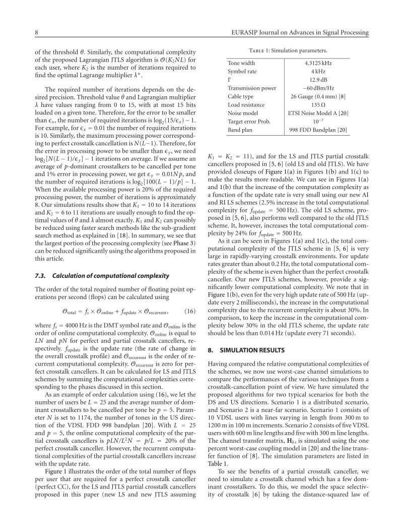
Table 1: Simulation parameters.
Tone width 4.3125 kHz
Symbol rate 4 kHz
Γ 12.9 dB
Transmission power −60dBm/Hz
Cable type 26 Gauge (0.4mm) [8]
Load resistance 135Ω
Noise model ETSI Noise Model A [20]
Target error Prob. 10−7
Band plan 998 FDD Bandplan [20]
K1 = K2 = 11), and for the LS and JTLS partial crosstalkcancellers proposed in [5, 6] (old LS and old JTLS). We haveprovided closeups of Figure 1(a) in Figures 1(b) and 1(c) tomake the results more readable. We can see in Figures 1(a)and 1(b) that the increase of the computation complexity asa function of the update rate is very small using our new AIand RI LS schemes (2.5% increase in the total computationalcomplexity for fupdate = 500Hz). The old LS scheme, pro-posed in [5, 6], also performs well compared to the old JTLSscheme. It, however, increases the total computational com-plexity by 24% for fupdate = 500Hz.
As it can be seen in Figures 1(a) and 1(c), the total com-putational complexity of the JTLS scheme in [5, 6] is verylarge in rapidly-varying crosstalk environments. For updaterates greater than about 0.2Hz, the total computational com-plexity of the scheme is even higher than the perfect crosstalkcanceller. Our new JTLS schemes, however, provide a sig-nificantly lower computational complexity. We note that inFigure 1(b), even for the very high update rate of 500Hz (up-date every 2milliseconds), the increase in the computationalcomplexity due to the recurrent complexity is about 30%. Incomparison, to keep the increase in the computational com-plexity below 30% in the old JTLS scheme, the update rateshould be less than 0.014Hz (update every 71 seconds).
8. SIMULATION RESULTS
Having compared the relative computational complexities ofthe schemes, we now use worst-case channel simulations tocompare the performances of the various techniques from acrosstalk-cancellation point of view. We have simulated theproposed algorithms for two typical scenarios for both theDS and US directions. Scenario 1 is a distributed scenario,and Scenario 2 is a near-far scenario. Scenario 1 consists of10 VDSL users with lines varying in length from 300m to1200m in 100m increments. Scenario 2 consists of five VDSLusers with 600m line lengths and five with 300m line lengths.The channel transfer matrix, Hk, is simulated using the onepercent worst-case couplingmodel in [20] and the line trans-fer function of [8]. The simulation parameters are listed inTable 1.
To see the benefits of a partial crosstalk canceller, weneed to simulate a crosstalk channel which has a few dom-inant crosstalkers. To do this, we model the space selectiv-ity of crosstalk [6] by taking the distance-squared law of

A. R. Forouzan and L. M. Garth 9
0.01 0.1 1 10 100 500 40001e8
5.87e8
29.4e8
1e10
1e11
1e13
5e13
Update rate (Hz)
Totalfl
opspersecond
Perfect CCNew LSOld LS
New JTLSOld JTLS
(a)
100 250 500 1000 400058.7e7
70.4e776.3e7
172e7
200e7
294e7
Update rate (Hz)
Totalfl
opspersecond
Perfect CCNew LS
Old LSNew JTLS
(b)
0.01 0.1 0.18
58.7e7
100e7
294e7
Update rate (Hz)
Totalfl
opspersecond
Perfect CCNew LSOld LS
New JTLSOld JTLS
(c)
Figure 1: (a) The total number of flops (including online and recurrent complexities) per user for perfect crosstalk canceller (perfect CC),our new LS scheme (new LS), the LS scheme in [5, 6] (old LS), our new JTLS schemes (new JTLS) assuming K1 = K2 = 11, and the JTLSscheme in [5, 6] (old JTLS) for L = 25 and p = 5, (b) a closer look at the performance of our LS scheme, the LS scheme in [5, 6], and ournew JTLS scheme and (c) a closer look at the performance of the JTLS scheme in [5, 6].
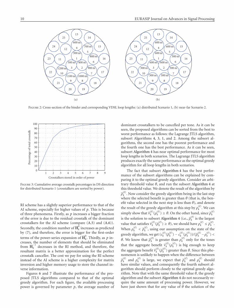
electromagnetic induction into account. Figure 2 illustratesthe cross-sections of the simulated 25-pair binder group forthe two scenarios. Each circle represents a twisted pair. Thelength of each VDSL loop is written in the corresponding cir-cle. The crosstalk couplings between pairs are considered tobe inversely proportional to the square of the distance be-tween the centers of the corresponding circles in Figure 2.7
As a worst-case scenario, we select a tightly packed subset of
7 The electromagnetic induction of twisted pairs into each other may notexactly follow the distance-squared law. However, our simulation resultswith a wide range of other powers for distance, ranging from
√2 to 4,
show that this does not affect the results reported in this article.
pairs at the center of the binder. The crosstalk couplings arenormalized so that they are equal to the one percent worst-case model for tangent circles (e.g., pairs 1 and 2, 1 and 3, 2and 7, etc.). If we order the crosstalkers by power, Figure 3shows the resultant cumulative average crosstalk power per-centages for the 10 loops for the DS direction of Scenario1, using the distance-squared law. This figure has a sim-ilar shape to the experimental measurements reported inFigure 3 of [6].
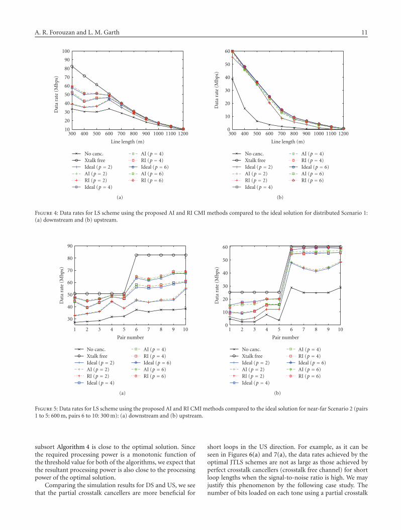
Figures 4 and 5 show the performances of the LS schemesusing the proposed CMI techniques for Scenarios 1 and 2, re-spectively. As it can be seen, both schemes nearly achieve theperformance of the ideal LS partial crosstalk canceller. The
10 EURASIP Journal on Advances in Signal Processing
1
300m
2
400m
3
500m
4
600m
5
700m
6
800m
7
900m
8
1000m
9
1100m10
1200m
11
12
1314
15
16
17
18
1920
21
22
23
24
25
(a)
1
600m
2
600m
3
600m
4
600m
5
600m
6
300m
7
300m
8
300m
9
300m10
300m
11
12
1314
15
16
17
18
1920
21
22
23
24
25
(b)
Figure 2: Cross-section of the binder and corresponding VDSL loop lengths: (a) distributed Scenario 1, (b) near-far Scenario 2.
1 2 3 4 5 6 7 8 90
10
20
30
40
50
60
70
80
90
100
Crosstalkers stored in order of power
Percentage
oftotalcrosstalk
Figure 3: Cumulative average crosstalk percentages in DS directionfor distributed Scenario 1 (crosstalkers are sorted by power).
RI scheme has a slightly superior performance to that of theAI scheme, especially for higher values of p. This is becauseof three phenomena. Firstly, as p increases a bigger fractionof the error is due to the residual crosstalk of the dominantcrosstalkers for the AI scheme (compare (A.5) and (A.6)).
Secondly, the condition number of H0k increases as predicted
by (7), and therefore, the error is bigger for the first-order
terms of the power-series expansion of H0k. Thirdly, as p in-
creases, the number of elements that should be eliminatedfrom H
−1k decreases in the RI method, and therefore, the
resultant matrix is a better approximation for the perfectcrosstalk canceller. The cost we pay for using the RI schemeinstead of the AI scheme is a higher complexity for matrixinversion and higher memory usage to store the channel in-verse information.
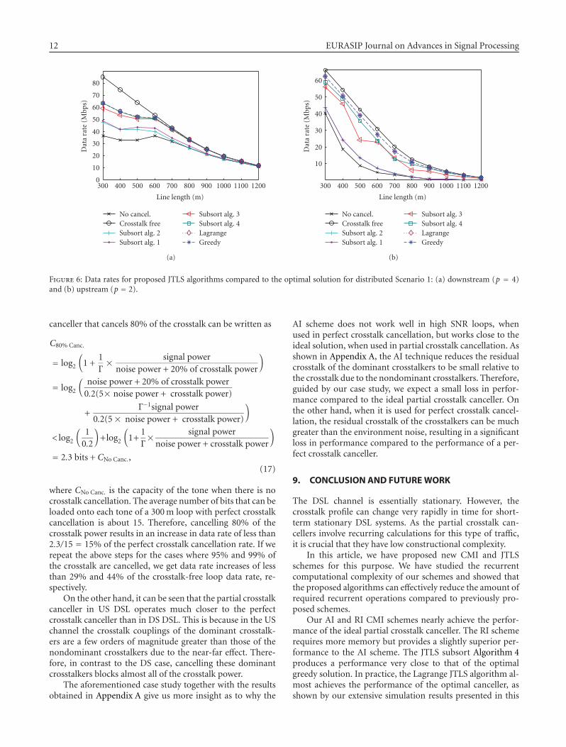
Figures 6 and 7 illustrate the performance of the pro-posed JTLS algorithms compared to that of the optimalgreedy algorithm. For each figure, the available processingpower is governed by parameter p, the average number of
dominant crosstalkers to be cancelled per tone. As it can beseen, the proposed algorithms can be sorted from the best toworst performance as follows: the Lagrange JTLS algorithm,subsort Algorithms 4, 3, 1, and 2. Among the subsort al-gorithms, the second one has the poorest performance andthe fourth one has the best performance. As it can be seen,subsort Algorithm 4 has near optimal performance for mostloop lengths in both scenarios. The Lagrange JTLS algorithmproduces exactly the same performance as the optimal greedyalgorithm for all loop lengths in both scenarios.
The fact that subsort Algorithm 4 has the best perfor-mance of the subsort algorithms can be explained by com-paring it to the optimal greedy algorithm. Consider an arbi-trary threshold value θ, and run the subsort Algorithm 4 atthis threshold value. We denote the result of the algorithm by
ρ(�)k . Now consider the greedy algorithm being in the last stepwhere the selected benefit is greater than θ (that is, the ben-efit value selected in the next step is less than θ), and denotethe result of the greedy algorithm at this step by ρ(�)k . We can
simply show that v(�)k (ρ(�)k ) ≥ θ. On the other hand, since ρ(�)k
is the solution to subsort Algorithm 4 (i.e., ρ(�)k is the largest
value that satisfies v(�)k (ρ(�)k ) ≥ θ), we should have ρ(�)k ≤ ρ(�)k .
When ρ(�)k < ρ(�)k , using our assumption on the state of the
greedy algorithm, we get (c(�)k (ρ(�)k )− c(�)k (ρ(�)k ))/(ρ(�)k −ρ(�)k ) <
θ. We know that ρ(�)k is greater than ρ(�)k only for the tones
that the aggregate benefit v(�)k (ρ(�)k ) is big enough to keep
the aggregate benefit v(�)k (ρ(�)k ) greater than θ. Since this phe-nomenon is unlikely to happen when the difference between
ρ(�)k and ρ(�)k is large, we expect that ρ(�)k and ρ(�)k shouldhave similar values, and consequently the fourth subsort al-gorithm should perform closely to the optimal greedy algo-rithm. Note that with the same threshold value θ, the greedyalgorithm and the subsort Algorithm 4 do not necessarily re-quire the same amount of processing power. However, wehave just shown that for any value of θ the solution of the
A. R. Forouzan and L. M. Garth 11
300 400 500 600 700 800 900 1000 1100 120010
20
30
40
50
60
70
80
90
100
Line length (m)
Datarate(M
bps)
No canc.Xtalk freeIdeal (p = 2)AI (p = 2)RI (p = 2)Ideal (p = 4)
AI (p = 4)RI (p = 4)Ideal (p = 6)AI (p = 6)RI (p = 6)
(a)
300 400 500 600 700 800 900 1000 1100 12000
10
20
30
40
50
60
Line length (m)
Datarate(M
bps)
No canc.Xtalk freeIdeal (p = 2)AI (p = 2)RI (p = 2)Ideal (p = 4)
AI (p = 4)RI (p = 4)Ideal (p = 6)AI (p = 6)RI (p = 6)
(b)
Figure 4: Data rates for LS scheme using the proposed AI and RI CMI methods compared to the ideal solution for distributed Scenario 1:(a) downstream and (b) upstream.
1 2 3 4 5 6 7 8 9 10
30
40
50
60
70
80
90
Pair number
Datarate(M
bps)
No canc.Xtalk freeIdeal (p = 2)AI (p = 2)RI (p = 2)Ideal (p = 4)
AI (p = 4)RI (p = 4)Ideal (p = 6)AI (p = 6)RI (p = 6)
(a)
1 2 3 4 5 6 7 8 9 100
10
20
30
40
50
60
Pair number
Datarate(M
bps)
No canc.Xtalk freeIdeal (p = 2)AI (p = 2)RI (p = 2)Ideal (p = 4)
AI (p = 4)RI (p = 4)Ideal (p = 6)AI (p = 6)RI (p = 6)
(b)
Figure 5: Data rates for LS scheme using the proposed AI and RI CMI methods compared to the ideal solution for near-far Scenario 2 (pairs1 to 5: 600m, pairs 6 to 10: 300m): (a) downstream and (b) upstream.
subsort Algorithm 4 is close to the optimal solution. Sincethe required processing power is a monotonic function ofthe threshold value for both of the algorithms, we expect thatthe resultant processing power is also close to the processingpower of the optimal solution.
Comparing the simulation results for DS and US, we seethat the partial crosstalk cancellers are more beneficial for
short loops in the US direction. For example, as it can beseen in Figures 6(a) and 7(a), the data rates achieved by theoptimal JTLS schemes are not as large as those achieved byperfect crosstalk cancellers (crosstalk free channel) for shortloop lengths when the signal-to-noise ratio is high. We mayjustify this phenomenon by the following case study. Thenumber of bits loaded on each tone using a partial crosstalk
12 EURASIP Journal on Advances in Signal Processing
300 400 500 600 700 800 900 1000 1100 12000
10
20
30
40
50
60
70
80
Line length (m)
Datarate(M
bps)
No cancel.Crosstalk freeSubsort alg. 2Subsort alg. 1
Subsort alg. 3Subsort alg. 4LagrangeGreedy
(a)
300 400 500 600 700 800 900 1000 1100 1200
10
20
30
40
50
60
Line length (m)
Datarate(M
bps)
No cancel.Crosstalk freeSubsort alg. 2Subsort alg. 1
Subsort alg. 3Subsort alg. 4LagrangeGreedy
(b)
Figure 6: Data rates for proposed JTLS algorithms compared to the optimal solution for distributed Scenario 1: (a) downstream (p = 4)and (b) upstream (p = 2).
canceller that cancels 80% of the crosstalk can be written as
C80% Canc.
= log2
(
1 +1Γ× signal power
noise power + 20% of crosstalk power
)
= log2
(
noise power + 20% of crosstalk power0.2(5× noise power + crosstalk power)
+Γ−1signal power
0.2(5× noise power + crosstalk power)
)
< log2
(
10.2
)
+log2
(
1+1Γ× signal powernoise power + crosstalk power
)
= 2.3 bits + CNo Canc.,(17)
where CNo Canc. is the capacity of the tone when there is nocrosstalk cancellation. The average number of bits that can beloaded onto each tone of a 300m loop with perfect crosstalkcancellation is about 15. Therefore, cancelling 80% of thecrosstalk power results in an increase in data rate of less than2.3/15 = 15% of the perfect crosstalk cancellation rate. If werepeat the above steps for the cases where 95% and 99% ofthe crosstalk are cancelled, we get data rate increases of lessthan 29% and 44% of the crosstalk-free loop data rate, re-spectively.
On the other hand, it can be seen that the partial crosstalkcanceller in US DSL operates much closer to the perfectcrosstalk canceller than in DS DSL. This is because in the USchannel the crosstalk couplings of the dominant crosstalk-ers are a few orders of magnitude greater than those of thenondominant crosstalkers due to the near-far effect. There-fore, in contrast to the DS case, cancelling these dominantcrosstalkers blocks almost all of the crosstalk power.
The aforementioned case study together with the resultsobtained in Appendix A give us more insight as to why the
AI scheme does not work well in high SNR loops, whenused in perfect crosstalk cancellation, but works close to theideal solution, when used in partial crosstalk cancellation. Asshown in Appendix A, the AI technique reduces the residualcrosstalk of the dominant crosstalkers to be small relative tothe crosstalk due to the nondominant crosstalkers. Therefore,guided by our case study, we expect a small loss in perfor-mance compared to the ideal partial crosstalk canceller. Onthe other hand, when it is used for perfect crosstalk cancel-lation, the residual crosstalk of the crosstalkers can be muchgreater than the environment noise, resulting in a significantloss in performance compared to the performance of a per-fect crosstalk canceller.
9. CONCLUSION AND FUTUREWORK
The DSL channel is essentially stationary. However, thecrosstalk profile can change very rapidly in time for short-term stationary DSL systems. As the partial crosstalk can-cellers involve recurring calculations for this type of traffic,it is crucial that they have low constructional complexity.
In this article, we have proposed new CMI and JTLSschemes for this purpose. We have studied the recurrentcomputational complexity of our schemes and showed thatthe proposed algorithms can effectively reduce the amount ofrequired recurrent operations compared to previously pro-posed schemes.
Our AI and RI CMI schemes nearly achieve the perfor-mance of the ideal partial crosstalk canceller. The RI schemerequires more memory but provides a slightly superior per-formance to the AI scheme. The JTLS subsort Algorithm 4produces a performance very close to that of the optimalgreedy solution. In practice, the Lagrange JTLS algorithm al-most achieves the performance of the optimal canceller, asshown by our extensive simulation results presented in this

A. R. Forouzan and L. M. Garth 13
1 2 3 4 5 6 7 8 9 1030
40
50
60
70
80
90
Pair number
Datarate(M
bps)
No cancel.Crosstalk freeSub-sort alg. 2Sub-sort alg. 1
Sub-sort alg. 3Sub-sort alg. 4LagrangeGreedy
(a)
1 2 3 4 5 6 7 8 9 100
10
20
30
40
50
60
Pair number
Datarate(M
bps)
No cancel.Crosstalk freeSub-sort alg. 2Sub-sort alg. 1
Sub-sort alg. 3Sub-sort alg. 4LagrangeGreedy
(b)
Figure 7: Data rates for proposed JTLS algorithms compared to the optimal solution for near-far Scenario 2 (pairs 1 to 5: 600m, pairs 6 to10: 300m): (a) downstream (p = 4) and (b) upstream (p = 4).
paper and other simulation results not reported here. Oursimulation results also show that the LS and JTLS schemesare particularly beneficial for crosstalk cancellation in shortloops in the US direction.
To further refine these results, it would be of interest tosimulate a VDSL network with variable-rate traffic, to findout how much processing power of the modems should bededicated to the online portion of the partial crosstalk can-celler and how often the structure of the partial crosstalk can-celler should be updated, based on the characteristics of thetraffic and the available processing power.
APPENDICES
A. CANCELLATION PROPERTIES OF (H0k)−1
In this appendix, we consider the cancellation properties of
(H0k)−1. Without loss of generality, we assume that the nor-
malizing factor βk is equal to one. Let us define HNDk
Δ=Hk−H
0k. MatrixH
NDk then contains the normalized crosstalk
factors of the nondominant crosstalkers with its diagonalelements equal to zero. The net effect of the partial crosstalk
precompensator (H0k)−1 on the channel can be written as
Hk(
H0k
)−1 = Λ(
H0k +H
NDk
)(
H0k
)−1 = Λ[
I +HNDk
(
H0k
)−1].
(A.1)
Note that the DSL DS channel exhibits row-wise diagonaldominance (RWDD) [2]. That is, the diagonal elements ofthe DS channel transfer matrix Hk are much larger than theoff-diagonal elements in the same row. In other words, for
any tone k and for any j �= i, we have
∣
∣h(i,i)k
∣
∣� ∣
∣h(i, j)k
∣
∣. (A.2)
The magnitude of diagonal dominance is measured by pa-rameter
α�= max
imaxj �=i
∣
∣h(i, j)k
∣
∣
∣
∣h(i,i)k
∣
∣
. (A.3)
Thus, we have α� 1. DefiningG0 Δ= I−H0k, from (6) we then
have maximax j|[G0]i j| = α. Using a power-series expansion
for (H0k)−1, we can write
Hk(
H0k
)−1 = Λ
{
I +HNDk
[
I +∞∑
�=1
(
G0)�]}
= Λ +ΛHNDk +ΛH
NDk
∞∑
�=1
(
G0)� .
(A.4)
The first and second terms of the last equality in (A.4)are the direct loop gains and the crosstalk factors ofthe nondominant crosstalkers, respectively. The third term,
ΛHNDk
∑∞�=1(G0)� , is the error term. The error term results in
residual crosstalk from the dominant crosstalkers.Consider an equal transmission power of pmax on all
loops. Assuming the transmitted symbols from differentusers are independent and identically distributed, the av-erage received crosstalk power on each loop due to the

14 EURASIP Journal on Advances in Signal Processing
nondominant crosstalkers is
1LTr[
ΛHNDk E
{
xkxHk}(
HNDk
)HΛH]
= pmax
LTr[
ΛHNDk
(
HNDk
)HΛH]
= pmax
L
L∑
i, j=1
∣
∣
∣
[
ΛHNDk
]
i j
∣
∣
∣
2.
(A.5)
Similarly, the average received power due to the error term is
pmax
LTr[
ΛHNDk SSH
(
HNDk
)HΛH]
= pmax
L
L∑
i, j=1
∣
∣
∣
[
ΛHNDk S
]
i j
∣
∣
∣
2
≤ pmax
L
L∑
i, j=1
[ L∑
m=1
∣
∣
∣
[
ΛHNDk
]
im
∣
∣
∣
2 L∑
n=1
∣
∣
∣
[
S]
nj
∣
∣
∣
2]
≤ pLα2
(1− pα)2pmax
L
L∑
i,m=1
∣
∣
∣
[
ΛHNDk
]
im
∣
∣
∣
2,
(A.6)
where SΔ= ∑∞
�=1 (G0)� . The first inequality follows from therelation |wHz|2 ≤ ‖w‖2‖y‖2. The upper bound for the sec-ond inequality occurs in the worst-case scenario when the pdominant crosstalkers in G0 are the same for all L loops andtheir crosstalk couplings are at the maximum value α, that is,
[
G0]
i j =⎧
⎨
⎩
α, 1 ≤ j ≤ p,
0, otherwise.(A.7)
Then we have
[(
G0)�]
i j=⎧
⎨
⎩
p�−1α� , 1 ≤ j ≤ p,
0, otherwise,(A.8)
and finally
L∑
n, j=1
∣
∣
∣
[
S]
nj
∣
∣
∣
2 ≤ pLα2
(1− pα)2. (A.9)
Since α < 0.01 [21], p is typically around 3 to 4, and L = 25,comparing (A.5) and (A.6), the average power due to the er-ror will be a fraction of the average power due to the non-dominant crosstalkers.
B. CONDITION NUMBER OF H0k
Define G0 Δ= IL − H0k. We have maximax j|[G0]i j| = α (see
Appendix A). Now consider Perron’s theorem [22, 23]: if{μ1, . . . ,μL} is an arbitrary set of positive numbers, then alleigenvalues {λ�G : � = 1, . . . ,L} of matrix G lie on the disk|z| ≤ mμ, where
mμ = max1≤i≤L
L∑
j=1
μj
μi
∣
∣g(i, j)∣
∣. (B.1)
By simply assuming μj = 1 for all j, we get
∣
∣λmaxG0
∣
∣ ≤ max1≤i≤L
L∑
j=1
∣
∣
∣[G0]i j∣
∣
∣ ≤ pα. (B.2)
To translate this result back to matrix H0k, note that from
G0 = IL − H0k, we have λG0 = 1 − λH0
k. Therefore, we find
that |λmaxH
0k| ≤ 1 + pα, and as long as pα ≤ 1 we have |λmin
H0k| ≥
1− pα. Thus, the condition number ofH0k is bounded by
∣
∣λmaxH
0k
∣
∣
∣
∣λminH
0k
∣
∣
≤ 1 + pα
1− pα. (B.3)
ACKNOWLEDGMENT
Part of this work has been presented at IEEE InternationalConference on Communications, Istanbul, Turkey, June 11-15, 2006.
REFERENCES
[1] T. M. Starr, M. Sorbara, J. M. Cioffi, and P. J. Silverman, DSLAdvances, Prentice-Hall, Upper Saddle River, NJ, USA, 2003.
[2] G. Ginis and J. M. Cioffi, “Vectored transmission for digi-tal subscriber line systems,” IEEE Journal on Selected Areas inCommunications, vol. 20, no. 5, pp. 1085–1104, 2002.
[3] R. Cendrillon, M. Moonen, J. Verlinden, T. Bostoen, and G.Ginis, “Improved linear crosstalk precompensation for DSL,”in Proceedings of IEEE International Conference on Acoustics,Speech and Signal Processing (ICASSP ’04), vol. 4, pp. 1053–1056, Montreal, Canada, May 2004.
[4] R. Cendrillon, M. Moonen, E. Van Den Bogaert, and G. Gi-nis, “The linear zero-forcing crosstalk canceler is near-optimalin DSL channels,” in Proccedings of IEEE Global Telecommuni-cations Conference (GLOBECOM ’04), vol. 4, pp. 2334–2338,Dallas, Tex, USA, November-December 2004.
[5] R. Cendrillon, M. Moonen, G. Ginis, K. Van Acker, T.Bostoen, and P. Vandaele, “Partial crosstalk cancellation forupstream VDSL,” EURASIP Journal on Applied Signal Process-ing, vol. 2004, no. 10, pp. 1520–1535, 2004.
[6] R. Cendrillon, G. Ginis, M. Moonen, and K. Van Acker, “Par-tial crosstalk precompensation in downstream VDSL,” SignalProcessing, vol. 84, no. 11, pp. 2005–2019, 2004.
[7] A. A. Salvekar, J. Louveaux, C. Aldana, J. L. Fang, E. de Car-valho, and J. M. Cioffi, “Profile detection in multiuser digi-tal subscriber line systems,” IEEE Journal on Selected Areas inCommunications, vol. 20, no. 5, pp. 1116–1125, 2002.
[8] “Spectrum management for loop transmission systems,”(Draft) ANSI Standard T1.417-2003, ANSI, Washington, DC,USA, February 2003.
[9] J. Cioffi, “Very-high-speed digital subscriber lines - systemrequirements,” Tech. Rep. T1E1.4/98 Contribution 043R6,ANSI, Washington, DC, USA, November 1998.
[10] C. Zeng, C. Aldana, A. A. Salvekar, and J. M. Cioffi, “Crosstalkidentification in xDSL systems,” IEEE Journal on Selected Areasin Communications, vol. 19, no. 8, pp. 1488–1496, 2001.
[11] P. Tsiaflakis, J. Vangorp, M. Moonen, J. Verlinden, and G. Yse-baert, “Partial crosstalk cancellation in a multi-user xDSL en-vironment,” in Proceedings of IEEE International Conference onCommunications (ICC ’06), vol. 7, pp. 3264–3269, Istanbul,Turkey, June 2006.

A. R. Forouzan and L. M. Garth 15
[12] A. Leshem and L. Youming, “A low complexity coordinatedFEXT cancellation for VDSL,” in Proceedings of the 11th IEEEInternational Conference on Electronics, Circuits and Systems(ICECS ’04), pp. 338–341, Tel Aviv, Israel, December 2004.
[13] G. Ginis, “Multi-line coordinated communication for broad-band access networks,” Ph.D. dissertation, StanfordUniversity,Stanford, Calif, USA, 2002.
[14] R. Cendrillon, M. Moonen, D. Gore, and A. Paulraj, “Lowcomplexity crosstalk cancellation through line selection in up-stream VDSL,” in Proceedings of IEEE International Conferenceon Acoustics, Speech and Signal Processing (ICASSP ’03), vol. 4,pp. 692–695, Hong Kong, April 2003.
[15] T. M. Starr, J. M. Cioffi, and P. J. Silverman, UnderstandingDigital Subscriber Line Technology, Prentice-Hall, Upper Sad-dle River, NJ, USA, 1999.
[16] S. Boyd and L. Vandenberghe, Convex Optimization, Cam-bridge University Press, Cambridge, UK, 2004.
[17] R. Cendrillon, M. Moonen, J. Verliden, T. Bostoen, andW. Yu,“Optimal multi-user spectrum management for digital sub-scriber lines,” in Proceedings of IEEE International Conferenceon Communications (ICC ’04), vol. 1, pp. 1–5, Paris, France,June 2004.
[18] W. Yu, R. Lui, and R. Cendrillon, “Dual optimization methodsfor multiuser orthogonal frequency division multiplex sys-tems,” in Proceedings of IEEE Global Telecommunications Con-ference (GLOBECOM ’04), vol. 1, pp. 225–229, Dallas, Tex,USA, November-December 2004.
[19] R. Sedgewick, Algorithms, Addison-Wesley, Reading, Mass,USA, 2nd edition, 1988.
[20] ETSI, “Transmission andMultiplexing (TM); access transmis-sion systems on metallic access cables; very high speed digi-tal subscriber line (VDSL)—part I: functional requirements,”ETSI Std. TS 101 270-1, Rev. V.1.3.1, 2003.
[21] R. Cendrillon, M. Moonen, R. Suciu, and G. Ginis, “Simpli-fied Power Allocation and TX/RX Structure for MIMO-DSL,”in Proceedings of IEEE Global Telecommunications Conference(GLOBECOM ’03), vol. 4, pp. 1842–1846, San Francisco, Calif,USA, December 2003.
[22] E. W. Weisstein, “Perron’s theorem,” http://mathworld.wol-fram.com/PerronsTheorem.html.
[23] I. S. Gradshteyn and I. M. Ryzhik, Tables of Integrals, Series,and Products, Academic Press, San Diego, Calif, USA, 2000.
Amir R. Forouzan received his B.S. andM.S. degrees in electrical engineering fromSharif University of Technology, Tehran,Iran, in 1998 and 2000, respectively, and hisPh.D. degree with highest distinction fromUniversity of Tehran in 2004. From August1999 to May 2004, he was with the IranTelecommunication Research Center as aResearch Fellow. Since June 2004, he hasbeen a Postdoctoral Fellow with the Uni-versity of Canterbury (UC), Christchurch, New Zealand. Duringthis period, he has been working on dynamic spectrum manage-ment and crosstalk cancellation schemes for digital subscriber lines(DSL). Since February 2006, he has been involved in establishingthe New Zealand Broadband Research Facility at the UC, wherehe has led a software project team in developing an advanced DSLsimulation tool. His research interests include dynamic spectrummanagement in DSL, optical CDMA, MIMO communication sys-tems and information theory, and ultrawideband radio.
Lee M. Garth received the B.S.E. degree(magna cum laude) from Princeton Uni-versity, Princeton, NJ, in 1987, and theM.S. and Ph.D. degrees from the Universityof Illinois at Urbana-Champaign, in 1989and 1996, respectively. He has had sum-mer employment with Raytheon Company,GTE Corporation, and MITRE Corpora-tion. From 1990 to 1996, he was a SeniorEngineer at Techno-Sciences, Inc., Urbana,IL. From 1996 to 2000, he was a Member of the Advanced DataCommunications Group of Bell Laboratories within Lucent Tech-nologies, Holmdel, NJ. Since 2000, he has been a Faculty Memberwith the Department of Electrical and Electronic Engineering atthe University of Canterbury, Christchurch, New Zealand. In 2006,he held a visiting appointment at the Samsung Advanced Instituteof Technology in South Korea. His research interests include sig-nal detection, array processing, adaptive equalization, and statisti-cal signal processing with applications to communications systems.He is a Senior Member of the IEEE and a Member of Tau Beta Pi.