research to study variable frequency drive … · miss vishu gupta, department of electrical...
TRANSCRIPT
A
DISSERTATION REPORT
ON
RESEARCH TO STUDY VARIABLE FREQUENCY DRIVE AND ITS ENERGY SAVINGS
Submitted for partial fulfillment of the requirement for the award of the
Degree of
MASTER OF TECHNOLOGY
In
ELECTRICAL ENGINEERING
With specialization in
POWER SYSTEM
Submitted to Supervised by Submitted by
M. Sashilal Vishu Gupta Tamal Aditya
HOD (Electrical) Asst. Professor (Electrical) (SGVU081491061)
SURESH GYAN VIHAR UNIVERSITY
JAIPUR
Department of Electrical Engineering
SURESH GYAN VIHAR UNIVERSITY, JAIPUR 2013

ii
CERTIFICATE
I Tamal Aditya hereby certify that the work which is being presented in the dissertation entitled
“RESEARCH TO STUDY VARIABLE FREQUENCY DRIVE AND ITS ENERGY
SAVINGS” in partial fulfillment of the requirements for the award of the Degree of M.TECH
and submitted in the Department of Electrical Engineering of SURESH GYAN VIHAR
UNIVERSITY, JAIPUR is an authentic record of my own work under the supervision of
Miss Vishu Gupta, Department of Electrical Engineering, Suresh Gyan Vihar University.
The matter presented in this dissertation embodies the result of own work and studies carried
own work and studies carried out by me and have not been submitted for the award of any other
degree of this or any other university.
This is to certify that the above statement made by the candidate is correct to best of my
knowledge.
Date:
(Vishu Gupta)
Asst. Professor (Electrical)

iii
ACKNOWLEDGEMENT
I take this opportunity to express my heartily gratitude and thank to my supervisor, Asst.
Professor of Department of Electrical Engineering Miss Vishu Gupta for her valuable technical
suggestions and full guidance towards completion of my dissertation from the beginning till the
end.
I would like to express my sincere thanks to whole Electrical Department of Suresh Gyan
Vihar University for constant inspiration, encouragement and co operating in my dissertation.
My appreciation also goes to my family, who has been so tolerant and supports me all these
days.
I would also like to thank to Mr. R. K Gupta (Programme Coordinator of M.Tech (DD)) and
Mr. M Sashilal (Head of Department of Electrical Engg.) for their contribution in preparing the
practical part of this Dissertation and to guide me towards the completion of this Dissertation.
Lastly, my gratitude goes to anyone who is involved directly or indirectly in this Dissertation.
(Tamal Aditya)

iv
ABSTRACT
As the demands of industrial needs varying the more outputs of the precise control of our basic
electrical prime movers i.e. motor. As compared to AC motors the DC motors are easy to control
but with increase in capacity they have their own limitations. Conversely AC motors particularly
the Squirrel Cage induction motors are more economical but the speed control of these motor are
quiet difficult because alteration of supply frequency is require. Nowadays with technological
advancement in drives system, the control of AC motors is more economically, easy to use and
the control the range of speed both below and above the base speed.
According to the requirement, these drives can fundamentally alter the voltage and the frequency
which is being fed to the motor using the technique called Pulse Width Modulation (PWM).
Because of user friendly feature and reasonable cost these devices are gaining more popularity.
As the Variable Frequency Device use the embedded system they can be programmed for
automatic control reducing the manual intervention and interfaced to the computer.
In the field of HVAC application the usage of Variable Frequency Drive have gained its number.
Air handler, chiller, pumps and tower fans are the common application of VFD. A better
understanding of Variable Frequency Drives with leads to improve in usage and determining of
some appliances and High Voltage AC systems. A basic knowledge of operations, its terms,
energy savings, and about the power factors is main aim of this dissertation also Harmonics
mitigation by VFD and a simulation project to show how VFD is beneficial for energy savings.
In addition to this paper will discuss the comparison between Variable Frequency Drives and
other technologies with respect to industrial standards.

v
Symbols and Abbreviations
Symbols
Ns Speed
Q Flow
H Head
P Power
Hz Hertz
ϕm Magnetic Flux
m Modulation Index
F Frequency
N Number of turn per phase
L Inductor
Istator Stator Current
Isw Switching Current
Rstator Stator Resistance
P Number of motor poles
Cosϕ Power Factor
ϕ Power Factor angle
wr Full load Copper Losses of the transformer

vi
V Voltage
Vrms Root Mean Square Voltage
Vn Line to Line Voltage
Te Electromagnetic Torque
w Speed
Wm Rotor Speed
Ohm
Fcn Function Block
Efficiency
Subscripts
a, b, c phase a, b or c
s stator quantity
r rotor quantity
Abbreviations
VFD Variable Frequency Drive
AC Alternating Current

vii
DC Direct Current
SCR Silicon Controlled Rectifier
HP Horse Power
ASD Adjustable Speed Drive
VSD Variable Speed Drive
KV Kilo Volt
KW Kilo Watt
MW Mega Watt
HVAC High Voltage Alternating Current
IGBT Insulated Gate Bipolar Transistor
RPM Revolutions per Minute
PWM Pulse Width Modulation
KVA Kilo Volt Ampere
NEMA National Electrical Manufactures Association
CSI Current Source Inverter
EMF Electromotive Force
PLC Programmable Logic Controller
CSF Carrier Switch Frequency
LCD Liquid Crystal Display

viii
PID Proportional Integral Derivative
BAS Building Automation System
THD Total Harmonic Distortion
IMD Inter Modulation Distortion
IP Intercept Point
SNR Signal to Noise Ratio
TDD Total Demand Distortion
DSP Digital Signal Processing
AFE Active Front End
LAN Local Area Network
SinuMec Sinusoidal Motor Efficiency Controller
RMS Root Mean Square
MOSFET Metal Oxide Semiconductor Field Effect Transistor
GTO Gate Turn Off Thyristor
VSC Voltage Source Converter
FFT Fast Fourier Transform
FLA Full Load Ampere
DPF Displacement Power Factor
TPF True Power Factor

ix
CONTENTS
CHAPTER NO.
CHAPTER NAME PAGE NO.
Certificate Acknowledgment Abstract Symbols and Abbreviation List of Figure List of Tables
ii iii iv v
xii xiii
1. Introduction 1.1 Variable Frequency Drive 1.2 Applying Variable Frequency Drives (VFD’s) 1.3 Easy Installation 1.4 Shrinking Cost and Size 1.5 Common VFD Terms 1.5.1 Variable Frequency Drive (VFD) 1.5.2 Adjustable Sped Drive (ASD) 1.5.3 Variable Speed Drive (VSD) 1.5.3.1 Mechanical Variable Speed Drive Method 1.5.3.2 Hydrostatic Variable Speed Drive Method 1.5.3.3 Electrical Variable Speed Drive Method 1.6 Energy Savings 1.7 Benefit of VFD in HVAC System 1.8 Manufactures 1.9 Controller
1 1 2 3 3 3 4 4 4 4 4 5 6 7 8 8
2. VFD Operation 2.1 Operation 2.2 Speed Control of Induction Motor 2.3 Constant V/f Ratio Operation 2.4 How Drive Changes the Motor Speed 2.5 Switching Bus with IGBTs 2.6 VFD as Starters 2.6.1 Low Inrush Motor Starting 2.6.2 Soft Starters 2.7 Low Full Load KVA 2.8 Load Characteristics of Induction Motor 2.8.1 Constant Torque and Variable Speed Load Characteristics 2.8.2 Variable Torque and Variable Speed Load Characteristics 2.8.3 Constant Power Load Characteristics 2.8.4 Constant Power and Constant Torque Load Characteristics 2.9 Commutation and Control Methods
9 9 10 11 12 13 14 15 15 16 17 18
19
19
19
19
x
2.9.1 Forced – Commutated VFD 2.9.2 Load – Commutated VFD 2.10 Automated Systems and Machine Control 2.11 Transmission Line Effects 2.12 Integrated Motor and Drives 2.13 Dynamic Braking 2.14 VFD Display and Keypad 2.15 Variable Frequency Drive Design Consideration
19 20 20 21 22 23 23 24
3. Relation Between VFD and Power Factor 3.1 General 3.2 Problems of Low Power Factor 3.2.1 Current Drawn 3.2.2 Cable Losses 3.2.3 Transformer Losses 3.2.4 Voltage Regulation 3.2.5 Levy of Penalty 3.3 Benefits of Power Factor Improvement
25 25 26 26 27 28 29 29 30
4. Harmonics and its Effect 4.1 Variable Frequency Drive and Harmonics Distortion 4.2 Harmonic Definition 4.3 Are Harmonics Harmful? 4.4 Introduction to Harmonic Terms 4.4.1 Distortion 4.4.1.1 Total Harmonic Distortion (THD) 4.4.1.1.1 Total Harmonic Voltage Distortion-THD(V) 4.4.1.1.2 Total Harmonic Current Distortion-THD(I) 4.4.1.2 Total Harmonic Distortion plus Noise 4.4.1.3 Total Demand Distortion-TDD 4.5 Harmonics Mitigating Techniques 4.5.1 Passive Technique 4.5.1.1 Line Reactors 4.5.1.2 Capacitor – Based Passive Filter 4.5.2 Active Technique 4.5.3 Hybrid Technique 4.6 Power Line Harmonics 4.7 Multi-Pulse VFDs 4.7.1 Twelve Pulse Design
31 31 31 31 32 32 32 32 33 33 33 34 34 34 34 35 35 35 36 36
5. Comparison Between VFD and Other Technologies 5.1 General 5.2 The SinuMEC Advantage 5.2.1. Pure Sine Vs Harmonic 5.2.2 Possible Solutions 5.3 Internal Losses 5.4 Motor Life Expectancy 5.5 Price 5.6 Advantage of VFD over SinuMEC
38 38 38 38 39 39 39 41 41

xi
5.7 With so many Disadvantages, Why there are VFDs? 5.8 Difference Between SinuMEC and VFD 5.9 Why VFD Why not Cycloconverter 5.10 Advantage and Disadvantage of VFD 5.10.1 Advantages of VFD 5.10.2 Disadvantages of VFD
41 42 43 43 43 43
6. Simulation 6.1 Aim 6.2 Theory 6.3 Building and Simulation of the PWM Motor Drive 6.3.1 Assembling and Configuring the Motor Blocks 6.3.2 Loading and Driving the Motors 6.3.3 Controlling the Inverter Bridge with a Pulse Generator 6.3.4 Displaying Signal and Measuring Fundamental Voltage and Current 6.3.5 Simulation with continuous algorithm of PWM Motor Drive 6.3.6 at full voltage the result of simulation by PWM Motor Drive 6.3.7 Using the Multimeter Block 6.3.8 Discretizing the PWM Motor Drive 6.3.9 Performing Harmonics Analysis using the FFT Tool 6.3.10 Analysis of Line to Line Voltage of Motor by Fast Fourier Transformation 6.4 Result
44 44 44 45 45 47 49 50
52
53
54 55 56 57
58
7. Conclusion and Future Work
60
Reference
62
xii
List of Figures
FIGURE NO.
FIGURE NAME
PAGE NO.
Fig. 1.1
Fig. 1.2
Fig. 1.3
Fig. 2.1
Fig. 2.2
Fig. 2.3
Fig. 2.4
Fig. 2.5
Fig. 2.6
Fig. 3.1
Fig. 3.2
Fig. 3.3
Fig. 3.4
Fig. 5.1
Fig. 6.1
Fig. 6.2
Fig. 6.3
Fig. 6.4
Fig.7.1
Variable Frequency Drive
Comparison of mechanical capacity control and
speed capacity control
Controller is connected to main supply and electrical machine
Mechanical capacity control
Circuit Diagram of Basic VFD
Drive Output Waveform Components
VFD soft starter panel
Four –Quadrant operation
Variable Controller
Power Triangle
Percentage increase in Current drawn
with increase in Power Factor
Percentage saving in losses with increase in power factor
Percentage increase in voltage
regulation with increase in Power Factor
Pulse Width Modulation of VFD
Simulation circuit of Variable Speed Motor Control
Simulation Graph of Voltage, Current, Speed and
Torque of the Asynchronous Motor
Simulation Graph of multimeter switches
FFT analysis of the Asynchronous motor
Circuit Diagram of Band Pass Filter
1
6
8
9
12
13
15
18
20
25
27
28
29
40
45
53
55
57
61

xiii
List of Tables
TABLE NO. TABLE NAME PAGE NO
Table No. 1.1
Table No. 6.1
Table No. 6.2
Table No. 6.3
Table No. 6.4
Table No. 6.5
Table No. 6.6
Table No. 6.7
Table No. 6.8
Table No. 6.9
Table No. 6.10
Relation between of flow, head and power with
respect to speed
Parameters of Universal Bridge
Parameters of Asynchronous Machine
Parameters of Discrete Three Phase PWM Generator
Parameter of Discrete Fourier Block
Parameters of Scope Block
Parameters of Data History in Scope Properties
Switch Currents of multimeter
Parameters of FFT present in powergui block
Data analysis of frequency
Calculation of order of Harmonics
6
46
47
49
50
51
51
54
56
58
59
1
CHAPTER 1
INTRODUCTION
1.1 Variable Frequency Drive
The industry of Variable Frequency Drive is growing rapidly and now it is more important for
technician and the maintenance personnel to keep the installation of VFD running smoothly. The
Variable Frequency Drive contains sufficient information for a technician to troubleshoot any
AC Variable, virtually eliminating the need for manufacturer-specific manuals.
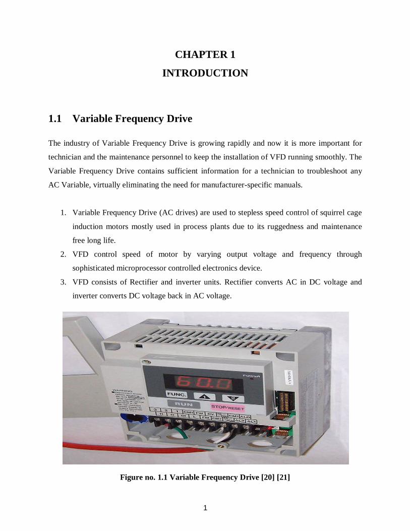
1. Variable Frequency Drive (AC drives) are used to stepless speed control of squirrel cage
induction motors mostly used in process plants due to its ruggedness and maintenance
free long life.
2. VFD control speed of motor by varying output voltage and frequency through
sophisticated microprocessor controlled electronics device.
3. VFD consists of Rectifier and inverter units. Rectifier converts AC in DC voltage and
inverter converts DC voltage back in AC voltage.
Figure no. 1.1 Variable Frequency Drive [20] [21]
2
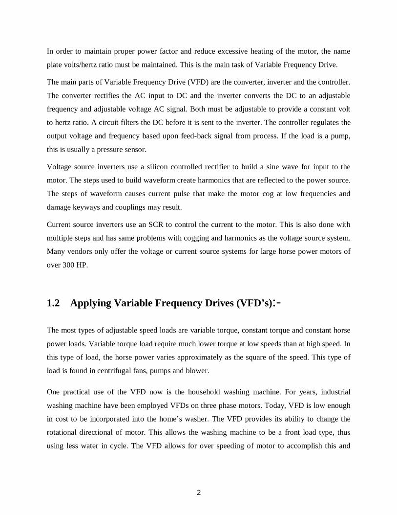
In order to maintain proper power factor and reduce excessive heating of the motor, the name
plate volts/hertz ratio must be maintained. This is the main task of Variable Frequency Drive.
The main parts of Variable Frequency Drive (VFD) are the converter, inverter and the controller.
The converter rectifies the AC input to DC and the inverter converts the DC to an adjustable
frequency and adjustable voltage AC signal. Both must be adjustable to provide a constant volt
to hertz ratio. A circuit filters the DC before it is sent to the inverter. The controller regulates the
output voltage and frequency based upon feed-back signal from process. If the load is a pump,
this is usually a pressure sensor.
Voltage source inverters use a silicon controlled rectifier to build a sine wave for input to the
motor. The steps used to build waveform create harmonics that are reflected to the power source.
The steps of waveform causes current pulse that make the motor cog at low frequencies and
damage keyways and couplings may result.
Current source inverters use an SCR to control the current to the motor. This is also done with
multiple steps and has same problems with cogging and harmonics as the voltage source system.
Many vendors only offer the voltage or current source systems for large horse power motors of
over 300 HP.
1.2 Applying Variable Frequency Drives (VFD’s):-
The most types of adjustable speed loads are variable torque, constant torque and constant horse
power loads. Variable torque load require much lower torque at low speeds than at high speed. In
this type of load, the horse power varies approximately as the square of the speed. This type of
load is found in centrifugal fans, pumps and blower.
One practical use of the VFD now is the household washing machine. For years, industrial
washing machine have been employed VFDs on three phase motors. Today, VFD is low enough
in cost to be incorporated into the home’s washer. The VFD provides its ability to change the
rotational directional of motor. This allows the washing machine to be a front load type, thus
using less water in cycle. The VFD allows for over speeding of motor to accomplish this and

3
thus the clothes get much dryer while still in washing machine. This means that the drying time
is reduced and saves electric costs overtime.
1.3 Easy Installation
The installation process of VFD is quite simple as many parts of equipments are industrial
manufactured and are transportable as each units are manufacture partly. The main parts of VFD
i.e. the line for communication; power controlling auxiliaries and the motor connected wire all
are easily transportable. The cooling parts are also manufactured partly and are easily
transportable for its installation. There is only need to connect the installing contractor to the
power line supply to the VFD.
1.4 Shrinking cost and size
In today’s life Electrical motor control for the purpose of industrial are used by many drives.
Among these drives some are of fixed speed drives and some are of variable speed drive
depending upon their application. However in earlier times the drives of variable speed had
various limitations regarding their efficiencies, speed and space but after the invention of power
electronics device and the application into the drives the scene is completely transformed,
nowadays VSD which are constructed smaller in shape but also very efficient and highly
reliable. The usage of it is more logical when it applies with least expensive in cost and simple to
implement.
1.5 Common VFD Terms
For controlling speed of the motor there are several terms used in the industrial field. The terms
are used to have different meanings, while the acronyms are often used interchangeably.

4
1.5.1 Variable Frequency Drive (VFD) For controlling the speed of the motor, this device basically consists of Power electronics
equipments which aim to vary the supply frequency of the system.
1.5.2 Adjustable Speed Drive (ASD) It is a more generic terms for the application in the field of mechanical and electrical for
the means of speed controlling.
1.5.3 Variable Speed Drive (VSD) This type of drives is used for controlling the speed of the driven equipments by the
motor or the motor itself. Basically this type of devices are used in the speed drives of
mechanical, electrical or hydrostatic types.
1.5.3.1Mechanical Variable Speed Drive Method
Historically, electrical VSD’s (Variable Speed Drives) even DC Drives were complex and
expensive and were only used for most important and difficult applications. The mechanical
drives were developed for insertion between a fixed speed electric drive motor and shaft of the
driven machine. Many engineers (mainly Mechanical Engineer) are still favored the Mechanical
Variable Speed Drives for some applications mainly because of simplicity and low cost.
There are two types of mechanical variable speed drives:-
1. Belt and Chain Drives with adjustable diameter sheaves
2. Metallic friction drives
1.5.3.2 Hydrostatic Variable Speed Drive method
This type of hydraulic VSD is most commonly used in mobile equipment such as transportation,
earth moving mining machinery. A prime mover is basically responsible for driven a hydraulic
pump usually at a fixed speed and transfer the hydraulic fluid to hydraulic motor. The hydraulic

5
motor and pump are usually housed in the same casing that allows closed circuit circulation of
the hydraulic fluid from pump to motor and back.
The speed of hydraulic motor is directly proportional to the rate of flow of fluid and the
displacement motor the hydraulic motor. Consequently the VSD is based on control of both fluid
flow and displacement of motor and /or adjustment of the pump. Practically these drives are
capable of a stepless adjustable from zero to full synchronous speed.
For making a hydraulic VSD ideal for earthmoving and mining equipments, the main advantages
of hydraulic Variable Speed Drives are:-
1. High torque available at low speed
2. High power to weight ratio
3. The drive unit does not damaged even it is stalls at full speed
4. Hydrostatics VSDs are normal bi-directional
Up to a power rating of 25 KW, the output speed can be varied smoothly from about 40rev/min
to 1450rev/min. Speed adjustment can be done manually from a hand-wheel or remotely using a
servo-motor. The main disadvantage is poor holding capability. Speed may drop by up to
35rev/min between 0% and 100% load. Hydraulic speed drives are basically two types:-
1. Hydrodynamic types
2. Hydrostatic types
1.5.3.3 Electrical Variable Speed Drive Method
In contrast to the variable speed control method of mechanical and hydraulic speed drive, the
electrical variable speed drives are basically the speed of electric motor itself, rather than a
intermediary device controlled. Variable speed drives that control the speed of DC motors are
loosely called DC Variable Speed Drives or simply DC Drives and those that control the Speed
of AC motors are called AC Variable Speed Drive or simply AC Drives. Almost all the electrical
VSDs are designed for operation from the standard three phase AC power system supply system.
6
Figure no. 1.2 comparing between the capacity control of mechanical and speed [20]
1.6 Energy savings
Savings in Energy can be work with the applications of Variable Frequency Drive (VFD). These
saving are achieved by eliminating throttling and friction losses affiliated with mechanical or
electromechanical adjustable speed technologies. Efficiency, quality and reliability can also be
improved. The application of variable frequency drive is load dependent.
Scope for power saving with Variable frequency Drive
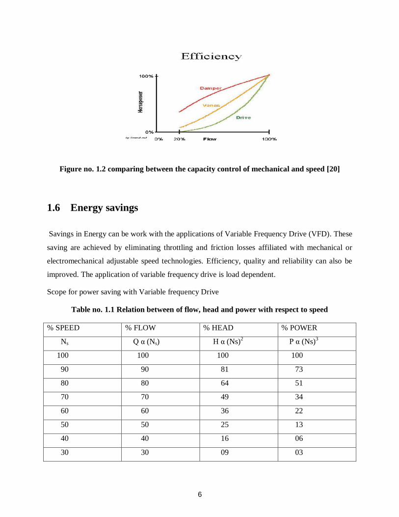
Table no. 1.1 Relation between of flow, head and power with respect to speed % SPEED % FLOW % HEAD % POWER
Ns Q α (Ns) H α (Ns)2 P α (Ns)3
100 100 100 100
90 90 81 73
80 80 64 51
70 70 49 34
60 60 36 22
50 50 25 13
40 40 16 06
30 30 09 03

7
As we know the variation of flow, head and power with respect to speed are as follows:
1. Flow α Speed
2. Head α (Speed)2
3. Power α (Speed)3
The table shows the relation of flow, head and power with respect to speed for e.g. at 50% speed
flow reduces to 50%, head reduces to 25% and power reduces to 13%.
1.7 Benefit of VFD in HVAC System
The variable frequency drive (VFD) is the most successful energy management tool which ever
used in HVAC system. On cooling tower eliminates drawbacks associates with starter-controlled
fans. When a VFD is commanded to start the fan may be spinning. A VFD must correctly
identifies motor rotation, slow the motor down to zero speed (when opposite rotation is
detected), accelerate the motor in correct direction and not trip on an over-voltage or over-
current condition.
Mechanical brakes or anti-ratcheting device can be used to ensure that a fan doesn’t rotate in the
wrong direction. A VFD eliminates the anti-ratcheting devices, time delay relays, etc as well as
both the mechanical and electrical brakes.
In extreme cold weather condition the icing of tower can be averted by running the fan slower
than required that raising the temperature of process water and the tower. Keeping the heat in the
tower it also reverses a cooling tower fan. Thus VFD’s accomplished this function and
eliminates the reversing starters.
Likewise on hot days, when the air is thinner, fans can be run above 60Hz, providing additional
cooling capacity. The current and/or torque limit function of VFDs will limit the current of motor
such that the nameplate FLA rating is not exceeded. This is not possible without applying a
VFD.

8
1.8 Manufactures
1. Danfoss Graham.
2. ABB.
3. Yaskawa Electric.
1.9 Controller
The aim of the Power Electronic Drive Controller is to obtain optimum performance from the
motor, to obtain the maximum power from it over as wide a speed range as is required, to
achieve highest operating efficiency from the motor and to obtain the best dynamic performance
possible. In all case it is it is necessary for the motor and the controller to be matched together
carefully if overall optimum performance is to be achieved. Hence the starting point of
exploration into Variable Frequency Drive must be the motor, how it works, how it develops
torque and how to understand it when operating as Variable Speed Drive.
Earlier the Variable Speed Motors have been DC motors and they reigned supreme in this field
since electricity has been put to practical use. However there is an increasing area of application
where the DC motor is unable to satisfy the performance required or cope with environment
specified. In some cases it is the lack of commutator or brush gear which can decide on the use
of an AC Motor. In others it is the need for speeds above those achievable with a DC motor in
yet other it may be wish to apply a Variable Speed Controller to an existing fixed motor. It may
even be the ready availability of an AC motor which is the deciding factor. Whatever the reason
may be, the availability of a wide range of Variable Frequency Drive system is leading to a
steady increase in the use of AC variable speed motor drives throughout the industry and this
trend is clearly going to continue.
Figure no. 1.3 Controller is connected to main supply and electrical machine [20]
9
CHAPTER 2
VFD OPERATION
2.1 Operation
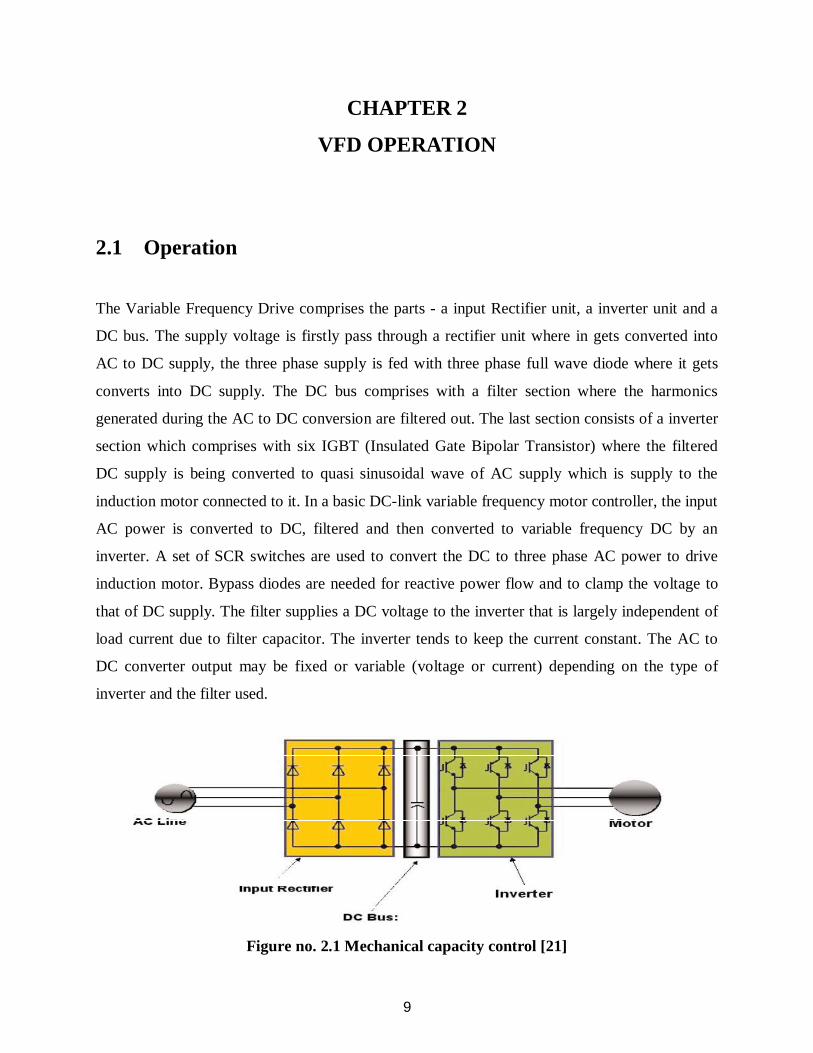
The Variable Frequency Drive comprises the parts - a input Rectifier unit, a inverter unit and a
DC bus. The supply voltage is firstly pass through a rectifier unit where in gets converted into
AC to DC supply, the three phase supply is fed with three phase full wave diode where it gets
converts into DC supply. The DC bus comprises with a filter section where the harmonics
generated during the AC to DC conversion are filtered out. The last section consists of a inverter
section which comprises with six IGBT (Insulated Gate Bipolar Transistor) where the filtered
DC supply is being converted to quasi sinusoidal wave of AC supply which is supply to the
induction motor connected to it. In a basic DC-link variable frequency motor controller, the input
AC power is converted to DC, filtered and then converted to variable frequency DC by an
inverter. A set of SCR switches are used to convert the DC to three phase AC power to drive
induction motor. Bypass diodes are needed for reactive power flow and to clamp the voltage to
that of DC supply. The filter supplies a DC voltage to the inverter that is largely independent of
load current due to filter capacitor. The inverter tends to keep the current constant. The AC to
DC converter output may be fixed or variable (voltage or current) depending on the type of
inverter and the filter used.
Figure no. 2.1 Mechanical capacity control [21]

10
As we know that the synchronous speed of motor is directly proportional to the supply
frequency, therefore synchronous speed of the motor can easily vary by changing the value of the
frequency. This is the main working phenomenon of the VFD.
Example:
For a 2-pole asynchronous motor, the synchronous speeds at different supply frequencies are:-
3600 rpm = ×
3000 rpm = ×
2400 rpm = ×
As the frequency can easily variable as compared with the poles of the motor therefore speed
control drive is termed as Variable Frequency Drive (VFD).
2.2 Speed control of Induction Motor
Basically synchronous speed and the rated speed are the two terms of speed used in motor. The
synchronous speed is defined as the speed of motor at which its magnetic field rotates. It is
basically the theoretical speed of the motor when the shaft of the motor bears no load and the
bearing of the motor faces no friction in the motor. The factors which affecting the synchronous
speed are the supply frequency and the stator magnetic poles. The calculation by which the
synchronous speed is to be calculated is given by the following equation:-
Speed (rpm) = ( )×.
Where;
Frequency = Supply Frequency of the Electrical power in Hz.
Number of Poles = Number of electrically magnetic poles presents in the stator of the motor.
In India, the supply frequency of the Electrical power is basically fixed i.e. 50Hz and the number
of poles presents in the stator is basically the factor of design which affects the speed of the

11
motor. In practical the rotor speed of the induction motor slightly lags as compared with the
synchronous speed at the time of running. This lags is basically expressed in percentage of the
synchronous speed which is called as “Slip”. Slip is basically defined as the difference of rated
speed from the synchronous speed and is divided with the synchronous speed. The equation for
slip calculation is given below:-
Slip = (
)
2.3 Constant V/F Ratio Operation
All Variable Frequency Drives (VFDs) maintain the output voltage – to – frequency (V/f) ratio
constant at all speeds for the reason that follows. The phase voltage V, frequency f and the
magnetic flux ϕ of motor are related by the equation:-
V = 4.444 f N ϕm or V/f = 4.444 ×N ϕm
Where N = number of turns per phase.
If the same voltage is applied at the reduced frequency, the magnetic flux would increase and
saturate the magnetic core, significantly distorting the motor performance. The magnetic
saturation can be avoided by keeping the ϕm constant. Moreover, the motor torque is the product
of stator flux and rotor current. For maintaining the rated torque at all speeds the constant flux
must be maintained at its rated value, which is basically done by keeping the voltage – to –
frequency (V/f) ratio constant. That requires the lowering the motor voltage in the same
proportion as the frequency to avoid magnetic saturation due to high flux or lower than the rated
torque due to low flux.
12
2.4 How Drive Changes Motor Speed
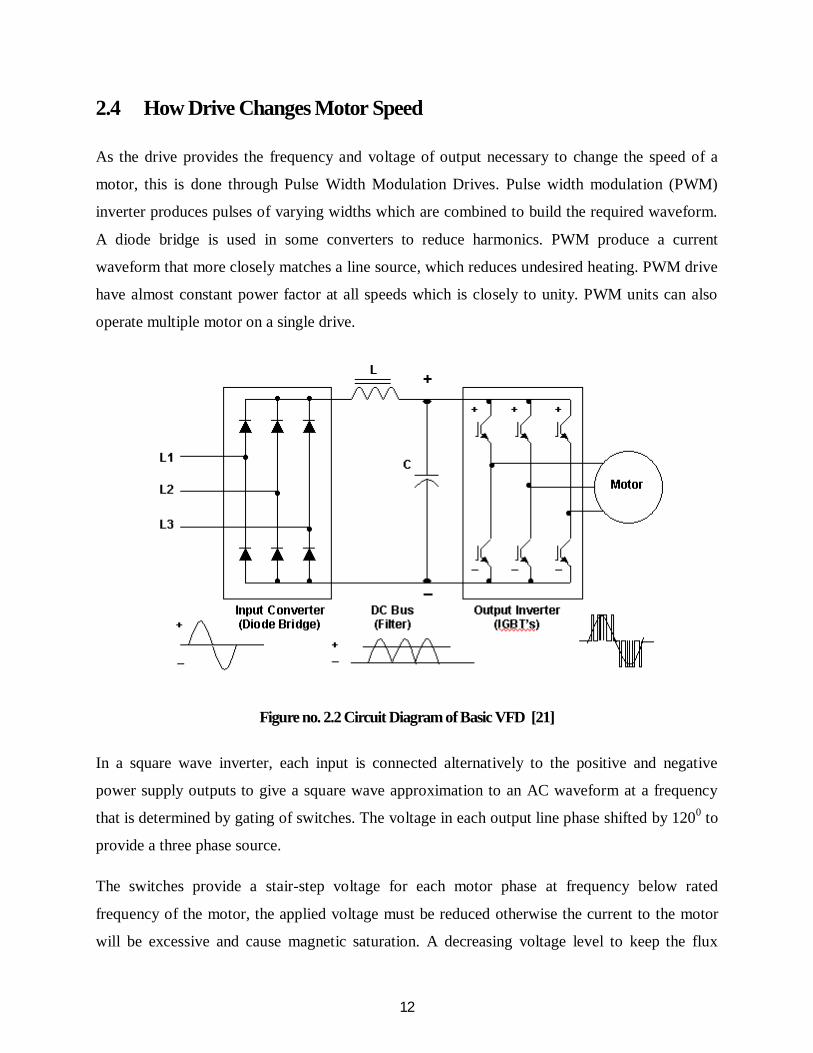
As the drive provides the frequency and voltage of output necessary to change the speed of a
motor, this is done through Pulse Width Modulation Drives. Pulse width modulation (PWM)
inverter produces pulses of varying widths which are combined to build the required waveform.
A diode bridge is used in some converters to reduce harmonics. PWM produce a current
waveform that more closely matches a line source, which reduces undesired heating. PWM drive
have almost constant power factor at all speeds which is closely to unity. PWM units can also
operate multiple motor on a single drive.
Figure no. 2.2 Circuit Diagram of Basic VFD [21]
In a square wave inverter, each input is connected alternatively to the positive and negative
power supply outputs to give a square wave approximation to an AC waveform at a frequency
that is determined by gating of switches. The voltage in each output line phase shifted by 1200 to
provide a three phase source.
The switches provide a stair-step voltage for each motor phase at frequency below rated
frequency of the motor, the applied voltage must be reduced otherwise the current to the motor
will be excessive and cause magnetic saturation. A decreasing voltage level to keep the flux
13
constant can be done with square wave inverter decreasing DC voltage as motor speed is reduced
below the rated speed. This can be done by a controlled rectifier but this problem with harmonics
in the power system of supplying controller.
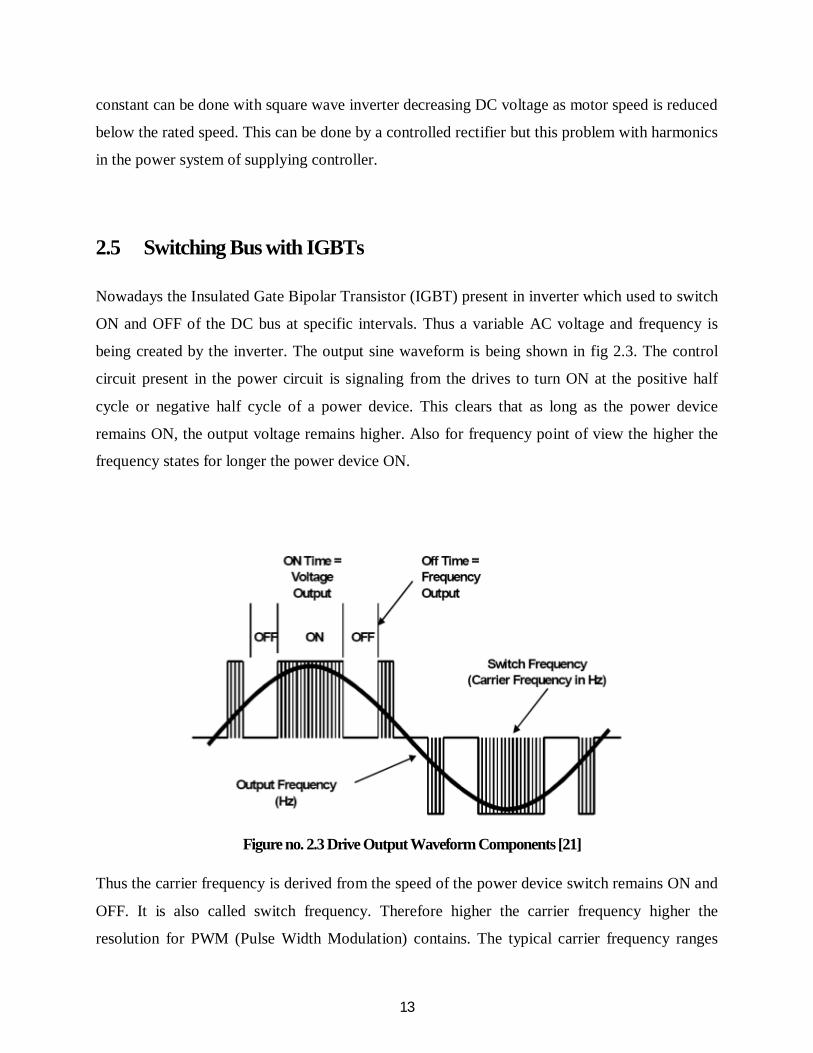
2.5 Switching Bus with IGBTs
Nowadays the Insulated Gate Bipolar Transistor (IGBT) present in inverter which used to switch
ON and OFF of the DC bus at specific intervals. Thus a variable AC voltage and frequency is
being created by the inverter. The output sine waveform is being shown in fig 2.3. The control
circuit present in the power circuit is signaling from the drives to turn ON at the positive half
cycle or negative half cycle of a power device. This clears that as long as the power device
remains ON, the output voltage remains higher. Also for frequency point of view the higher the
frequency states for longer the power device ON.
Figure no. 2.3 Drive Output Waveform Components [21] Thus the carrier frequency is derived from the speed of the power device switch remains ON and
OFF. It is also called switch frequency. Therefore higher the carrier frequency higher the
resolution for PWM (Pulse Width Modulation) contains. The typical carrier frequency ranges

14
from 3KHz to 4 KHz or 3000 to 4000 times per second as compared with older SCR based
carrier frequency which ranges from 250 to 500 times per second. Thus it is clear as much as
higher the carrier frequency higher will be the resolution of output waveform. It is also noted that
the carrier frequency decreases the efficiency of the drive because it led to increase the heat of
the drive circuit.
2.6 VFD as Starters
Variable Speed Drives (VSDs) take place of a starter. They have both starting capability and
overload protection built in. In fact the microprocessor control the most drives provides
additional protection against other faults (such as under-voltage, over-voltage, ground fault, loss
of phase, etc.). Variable Speed Drives also provide for soft-start of the motor (if so programmed)
reducing inrush current and reducing wear on belts and sheaves. While a starter not required
when a VSD/VFD is used, one may be provided as a back up to the drive so that the motor can
be run at a full speed in case the drive fails. The Variable Frequency Drive as a starter has
following advantage:-
1. It provides a high starting torque compared to other methods.
2. Line current can be made sinusoidal with displacement power factor unity with a pulse
width modulation (PWM) rectifier.
3. The same converter can be used on a time-sharing mode for other motors.
4. The converter can be bypassed after starting the motor to eliminate the converter losses.
5. At light loads the voltage can be adjusted to improve the running efficiency.
The Variable Frequency as a starter is very similar to Variable Frequency Drives (VFDs) in
design and is gradually becoming widely used due to falling power electronics prices and
stringent power quality standards on the line harmonics imposed on the variable frequency
motor drives.

15
2.6.1 Low Inrush Motor Starting
Small induction motors can be started directly from lines. However, the starting inrush current in
a large motor with high inertia can be high and last for a prolonged time, causing the motor to
overheat. Moreover the lights may flicker under excessive voltage dip in the lines. Using a star –
delta starter, an autotransformer or a phase controlled voltage step-down converter, the starting
the motor with reduced voltage. All these methods result in low starting torque proportional to
the applied voltage squared and are not really for starting a large motor with high initial torque
load.
2.6.2 Soft Starters
During soft starting of a motor, the frequency and the voltage starts from a small value and ramp
up to a full rated value in a linear ramp. However, near zero speed and frequency at starting, the
inductive reactance is negligible and the voltage setting the air gap flux is V-IstatorRstator. For
constant air gap flux requires then (V-IstatorRstator)/f must be maintained constant. The required
boost decays as the motor speeds up under increasing frequency and this ratio in the V/f ratio
linearly ramping up. The rate at which V and f are ramped up depends on the load inertia. The
ramping is done over a longer time for high inertia loads than for low inertia loads.
Figure no. 2.4 VFD soft starter panel
16
2.7 Low Full Load KVA
Basically the total amount of power present in KVA offers the limiting factor of energy that is to
be transferred though other electrical devices. During period of peak demand if the required
KVA by the equipments can be reduced then it will help to improve voltage sags, power
shortages of Power and blackouts. Power factor and the unity efficiency are evenly measured
while estimating Kilo Volt Ampere .This means that the power factor is indirectly proportional
to KVA, but the equipment may be equal or worse in efficiency.
To closely match with the load a backup generator is typically the same sized is provided. The
size of generator required can be reduced by lowering the KVA. with the application of Active
front are used in the Variable Frequency Drives the ratio of KW/KVA is tends to be ideal i.e. 1:1
which resulting effect on the size of the generator, This is the reason that the power factor tend to
unity and also the harmonics that give rise from the Variable Frequency Drive is very less. Also
decreasing the value of KVA acquires the usefulness objects. So from the usage of same
transmission objects the total power in (KW) can be conveyed.
A drive can control two main elements of a three phase induction motor. Basically the two parts
of the motor are the rotor and the stator which works through magnetic interaction. A motor
contains pair of pole. The iron pieces which are present in stator, wound in a specific pattern to
provide a north south magnetic field.
With one pole pair which is isolated in a motor the rotor shaft rotates at a specific speed which is
termed as base speed. This speed can be determines by the number of poles and the frequency
applied to it. The formula includes the effect called “slip”. Slip is basically the difference
between the speed of rotor and the stator magnetic field rotating. When a magnetic passes
through the conductor of the rotor, the magnetic field of the rotor takes on of its own. These
magnetic fields rotor will try to catch up to the rotating field of the stator. However this never
happens and thus the difference is called slip. The slip is what that allows a motor to turn.
Motor Slip:
Shaft Speed = 120 × F/P
Slip for NEMA B Motor = 3 to 5% of Base Speed which is 1800 RPM at Full Load
17
F = Frequency applied to the motor
P = Number of motor poles
Example:
Shaft Speed = ×.
By changing the frequency we can change the speed of motor. Another way to change the motor
speed by changing the no. of poles, but this change would be a physical change of the motor. It
would further require rewinding and result increase in step changing to the speed. So keep in
view of cost efficiency, convenience and precision, we change the frequency. Also the torque
developing characteristics of every motor is the volts per hertz (V/Hz). To change the motor
torque we can change this ratio. For example, an induction motor connected to a 460V,
60Hzsource then the ratio of (V/Hz) will be 7.67. Thus as long as this ratio stays in proportion
the motor will develop rated torque. A drive provides the output of many different frequencies.
By changing the given output frequency of the drive, we will get a new torque curve.
2.8 Load characteristics of Induction Motor
In practical, the loads are of different types with variable speed torque curves are available. As
develop motor torque is equal to requirement of load torque then the load system of the motor is
said to be stable. With comparison to the time constant of mechanical, in most drives the
electrical time constant of motor is negligible. Therefore during transient operation, the motor
can be assumed to be an electrically equilibrium, implying that the steady state torque speed
curve is also applicable to transient state operation.
Figure 8 represent the Four-quadrant diagram for mode of operation of variable speed drive. In
Quadrant 1 both the speed and torque represent in positive direction, therefore the Quadrant 1 is
termed as forward motoring quadrant. Similarly in Quadrant 3 both speed and torque represent in
negative direction, therefore it is termed as reverse motoring.

18
Figure no. 2.5 Four –Quadrant operation [20]
Similarly in Quadrant 2 and 4 both the speed and torque are mutually opposed each other which
resultant gives as braking effect. Thus both the quadrant 2 and 4 termed as reverse and forward
braking.
For a trouble free operation of VSDs, the characteristics of loads are particularly important. Load
refers to essentially to the output of torque and the corresponding speed required. Load
characteristics can be classified as follows:-
Constant torque and variable speed loads characteristics
Variable torque and variable speed load characteristics
Constant power loads characteristics
Constant power and constant load characteristics
2.8.1 Constant Torque and Variable Speed Load Characteristics The torque required by this type of load is constant regardless of speed. In contrast, the power is
linearly to the proportional of the speed. Equipments such as conveyors, screw compressors and
feeders have this type of characteristics.

19
2.8.2 Variable Torque and Variable Speed Load Characteristics
This is most commonly found in industry and sometime it is called as quadratic torque load. The
torque is the square of speed, while the power is the cube of the speed. This is typical torque
speed characteristics of a fan or a pump.
2.8.3 Constant Power Load Characteristics
This type of load is rare but is sometime found in industry. The torque varies while the power
remains constant. The torque is inversely proportional to the speed at which the theoretically
meaning is the infinite torque at zero speed and zero torque at the infinite speed. This type of
load is characteristics of the traction droves, which require high torque at low speeds for initial
acceleration and then a much reduced torque when at a running speed.
2.8.4 Constant Power and Constant Torque Load Characteristics
This is commonly applicable in the paper industry. With the linearly in the power increasing,
basically in this type of load as the speed increases, the torque is constant.
2.9 Commutation and Control Methods
There are basically two methods for the commutation of Variable Frequency Drive (VFD). These
are:-
2.9.1 Forced – Commutated VFD
With lagging power factor induction motor load, the inverter thyristors need to be forced
commutation with capacitor and diodes. The leakage inductance of the motor plays a significant
role in the commutating circuit design for the inverters. Therefore such VFD is designed for use

20
with only specific motor. Also it can be used for regenerative braking without additional circuits
on the positive side.
2.9.2 Load – Commutated VFD
The load – commutated thyristors in a CSI is widely used with large multi megawatt
synchronous motor for pumps, compressors, rolling mills and ship propulsion. For high power
drives, 12 pulse converters are used to lower harmonic content. The VFD is load – commutated
by leading power factor of the synchronous motor that can achieve by over exciting the rotor
field to obtain higher back – emf induced in motor armature. The frequency and the phases of the
three phase current are synchronized to the rotor position and the current commutation in the
inverter thyristor is accomplished by using motor back – emf. Slow speed thyristor can be used
both sides. This makes the inverter simple, cost effective, energy efficient and reliable compared
to CSI with an induction motor.
Figure no. 2.6 Variable Controller [21]
2.10 Automated Systems and Machine Control
The VFD is used to do more than vary the speed of an electric motor. First, in order to run the
motor, the VFD must be programmed for the control scheme that is expected to utilize. Next, the
VFD is expected in many automated systems to perform some minor logic operations,

21
determining when and how fast to run the motor it is controlling. Basic VFD control scheme
typically are called two wire or three wire control schemes. Two – wire control scheme utilize
just two wires for the sequencing (run/stop) phase of operation, whereas three wire scheme need
a third wire. Thus the starting, stopping and directional (motor rotation) commands necessary to
motor operation are picked up here. All machines with AC motors and VFD control have to have
a determination made as to how these signals are to be sequenced and from where they shall
come. The drive is not all knowing; the user must tell the drive this basic control scheme.
The reference is the term given to that signal that the drives receives, typically from an external
potentiometer or PLC controller, that directly relates to how fast it is to make the AC motor run .
Reference signal can be in a 0 to 10 volts DC, 0 to 5 Volts DC mode or can be 4 to 20
milliamperes. These signals can be scaled inside the drive to correspond to low and high speed of
the motor. They are usually bias adjustments for these signals, as many times as they are not true
and exact voltages. These flexibility by the VFD allows for deviations to be corrected.
Additional control terminal at the drives are low voltage inputs and outputs, with many being
configurable by the user for the machine or process. There are contacts to indicate that the VFD
is running ok and there are no faults. Additionally, many drives come equipped to send analog
signals out to drive – speed meters. Thus it is possible to utilize many control options whenever
setting up a VFD on any one machine. The VFDs, equipped with extensive and programmable
capabilities, can be made to be very different from different from one another when the machine
or automated – process needs have to be met.
2.11 Transmission line effects
The Variable Frequency Drive consists of a chain of pulses which is switched at the carrier
frequency of the output voltage of Pulse Width Modulation (PWM). The transmission line effect
of cable between drive and the motor must be considered as the rapid rise time of these pulses.
The pulses tend to reflect back from motor terminals into the cable, as the transmission line
impedance of cable and motor are different. Putting high stress on the cable and the motor
winding and also the eventual insulation failure the resulting voltage can produce up to twice the

22
rated line voltage for long cable runs. The longer Carrier Switching Frequencies (CSF) of 2.5
KHz is allowed by longer cable distances when the Carrier Switching Frequency can produce
audible noise at the motor. The manufacturers of Variable Speed Drives (VSD) usually after
du/dt filter that basically decrease the steepness of the pulses for application requiring long motor
cables whereas the sinus filter is recommended for very long cables or old motor is with
insufficient winding insulation . As the life of older motor is to be expected shorten therefore the
VFD should purchase as per the motor rated for applications.
2.12 Integrated Motor and Drives
A number of motor and drive manufactures are now producing integrated motor/VFD units.
These units consist of a motor and a specially designed VFD, produced as a single package, with
the VFD unit mounted on the variously on the top, side or end of the motor. Currently these
designs are available up to approximately 22 kW (30HP). Integrated motor and drives can
feature a number of advantages:-
1. Motor and VFD are properly matched.
2. Installed cost can be less than separate motor and VFD.
3. No special cables between VFD and motor, saving installation time and screened
cables.
4. Reduced over –voltage on the motor winding due to short length of connections,
leading to a longer life of insulation.
5. No output cables. Hence radiated emissions are minimized.
6. VFD shares motor cooling system.
7. Better compatibility between all components of the drive system, reduces noise and
vibration.
8. Often easier and faster to retrofit in a building or industrial installation.

23
2.13 Dynamic braking
Dynamic braking basically determines that when a motor used as a generator by absorb energy
from the system. The Variable Frequency Drive system includes a resistor/chopper combination
that allows for dynamic braking of the tripper. The VFD chopper/resistor system is designed to
handle a minimum of 15 stops (and 15 starts) per hour. During soft stop, the VFD will
dynamically slow the tripper to a full stop in a maximum of 3 seconds.
Normal stopping is done by dynamic braking only. Neither the motor brakes nor the rail clamps
are used during dynamic braking. This allows longer life on brake pads.
2.14 VFD Display and keypad
The operating values of VFDs are being displayed in engineering / user units. The display shall
be given in English words i.e. no alphanumeric codes are acceptable.
1. Motor speed (RPM, Percent and Engineering units)
2. Motor current
3. Calculated motor torque
4. Calculated motor power (KW)
5. Output frequency
6. Output voltage
7. DC Bus voltage
A backlit LCD display included in the keypad. The following assistants shall use the keypads:-
1. Start – up assistants
2. Parameter assistants
3. Maintenance assistance
4. Trouble shooting assistance

24
The keypad shall be removal, capable remote mounting and shall be allow for uploading and
downloading of parameter settings. It also includes the hand off auto selection and speed control.
There is a fault reset and help button on the keypad. The help button shall include “On – line”
assistants for programming and trouble shooting.
A built in time clock with a battery for a backup in the VFD keypad, the time clock shall be used
to date and time stamp faults and records of parameters operating at the time of fault. The VFD
automatically reverts to hours of operation since initial power up, if the battery fails. The time
clock also programmed to control the functions of start/stop constant speed, PID parameters sets
and output relays. The Variable Frequency Drive shall have capability of communicating
building automation system. (BAS) via a RS – 485 port.
2.15 Variable Frequency Drive Design Consideration
In providing a VFD in a new installation, all components can be designed accordingly. However
in a retrofit, installing a VFD is not as simple as changing the motor starter. All components need
to be carefully addressed. The system design needs to be analyzed. Several issues are noted in
the following list:-
1. A VFD normally requires a larger motor and a heavier wiring from the motor starter.
Special motors may be used that are provided with reinforced insulation.
2. A VFD is only about 96 or 97 percent efficient. The difference in the efficiency results in
the generation of substantial heat in the motor starter, which must be dissipated. As a
result the electrical room containing the VFD may require additional ventilation or air
conditioning.
3. VFDs are not recommended for high static head applications. Because of the
relationships between speed and horsepower, a much larger motor is typically needed for
high static head applications and may not be most efficient installation.
4. Other design issues include larger wiring required, potential resonance with other
equipment, long cable runs and potential induced voltages.

25
CHAPTER 3
RELATION BETWEEN VFD AND POWER FACTOR
3.1 General
The Variable Frequency Drive (VFD) basically contains capacitors which are present in DC bus
is used to maintain Power Factor on the line side. Therefore any additional use of other power
factor correction equipments on the line side supply to the motor or use of expensive capacitor
bank is not require. The Variable Frequency Drive (VFD) itself offer high power factor in the
line side supply to the motor.
Power Factor of an Electrical Network/Installation/Load is defined as the cosine of angle by
which the Apparent Power i.e. KVA is out of phase with respect to the Active Power i.e. KW. A
simple vector diagram is given below where Power Factor is equal to cosϕ (lagging).
KW
KVAr KVA
Figure no. 3.1 Power Triangle
We know that Power Factor = Cosϕ
From the above diagram-
1. KVA = (KW) + (KVAr)

26
2. Cosϕ = KW/KVA
= KW/ (KW) + (KVAr)
3. KW = KVA × Cosϕ
4. Tanϕ = KVAr/KW
It is now clear that in order to reduce the flow of reactive the Power Factor will have to be
improved. At unity Power Factor (i.e. Cosϕ =1) the flow of reactive power is zero and is thus the
ideal condition.
3.2 Problems of Low Power Factor:-
Low Power causes a variety of problems which result in increase in losses and in efficient system
operation. The major problems that are created due to low power factor are elaborated below:-
3.2.1 Current Drawn
For a given Active Power i.e. KW requirement a low Power Factor will result in an increase in
the current drawn for the supply. The graph given on the next page gives the variation of
percentage increase in the current drawn on the Power Factor decreases.
It can be seen from the graph that, if the percentage increase in current drawn at unity Power
Factor is 0% of the rated current the corresponding percentage increase in current drawn at 0.5
Power Factor will be 100% i.e. twice the rated current will be drawn. This means that with low
Power Factor the transformers, switchgear, distribution cables, etc in the installation will have to
be over sized to carry this increased current. In addition to this the I2R losses will increase
significantly due to low Power Factor.

27
Figure No. 3.2 Percentage increase in Current drawn
with increase in Power Factor
3.2.2 Cable Losses
As explained above improvement in Power Factor means reduction in the line current. For a
given cable the losses are proportional to the square of this current. Consequently by improving
Power Factor from an initial value of Cosϕ1 to the final value of Cosϕ2, the reduction in I2R
losses is given by the expression: –
Percentage Saving in losses
= {1-(Cosϕ1/Cosϕ2)2}×100
The graph given below shows the percentage saving in I2R losses. We can see an improvement
in Cosϕ from 0.7 to 0.9 reduces losses by 40%
0%
20%
40%
60%
80%
100%
0.9 0.8 0.7 0.6 0.5
curr
ent d
raw
n
Cosɸ
Percentage increases in current drawnwith increase in Power Factor

28
Figure No. 3.3 Percentage saving in losses with increase in power factor
3.2.3 Transformer Losses
The losses in transformer are generally two types:-
a. Losses in the core i.e. Iron Loss and
b. Losses in the winding i.e. Copper Loss
The Iron Loss are approximately equal to the power consumed by the transformer under no load
conditions and for all practical purposes are assumed to be constant irrespective of load variation
on the transformer. The Copper Loss however vary from the square of the current and thus
become directly related to the factor of the load which being supplied from the transformer. The
saving in transformer losses due to power factor improvement is given by the expression.
Saving in Loss = Wr × K1 [(1/Cosϕ1)-(1/Cosϕ2)]
where Wr = full load Copper Losses of the transformer
K1 =
0
10
20
30
40
50
60
70
80
0.5 0.6 0.7 0.8 0.9 1
Perc
enta
ge sa
ving
in
loss
es
Cosϕ (initial)
29
Cosϕ1 = Initial Power Factor
Cosϕ2 = Final Power Factor
Thus it is obvious that improvement in Power Factor has significant cost saving of reduction of
Transformer Losses.
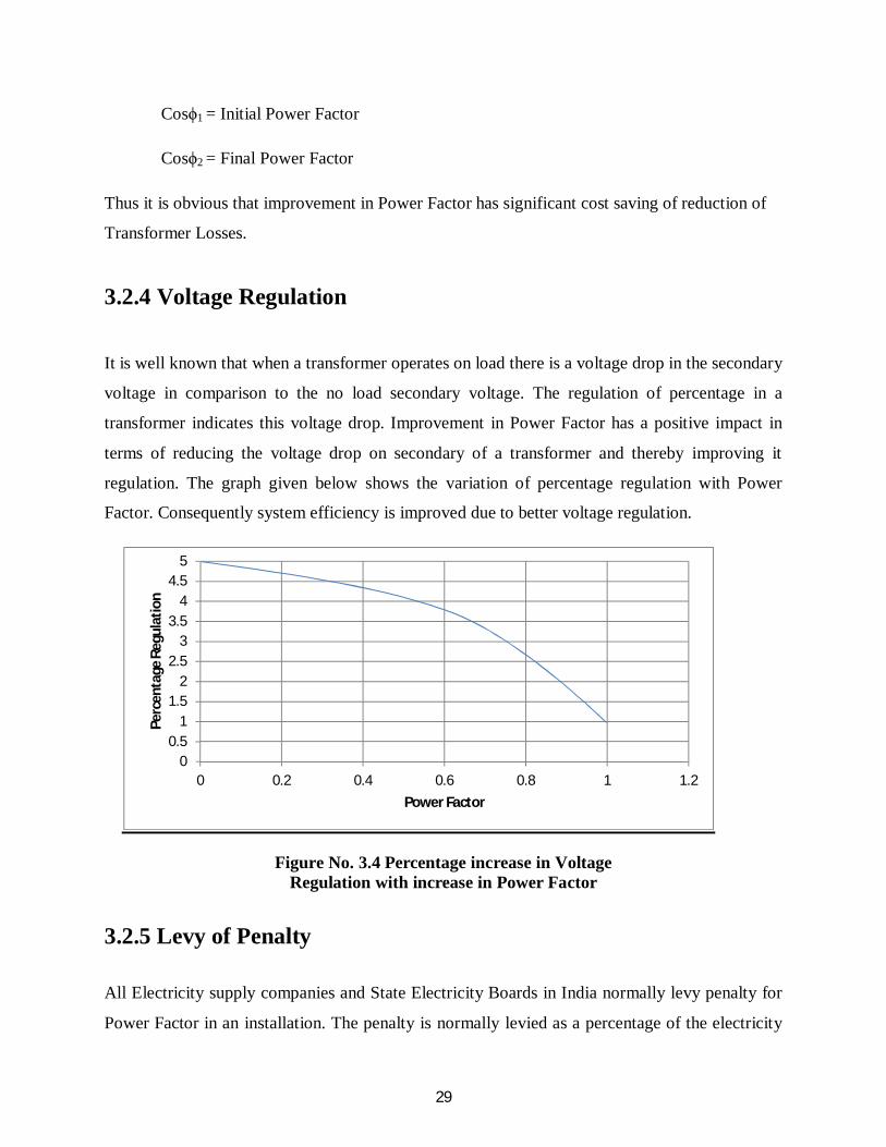
3.2.4 Voltage Regulation
It is well known that when a transformer operates on load there is a voltage drop in the secondary
voltage in comparison to the no load secondary voltage. The regulation of percentage in a
transformer indicates this voltage drop. Improvement in Power Factor has a positive impact in
terms of reducing the voltage drop on secondary of a transformer and thereby improving it
regulation. The graph given below shows the variation of percentage regulation with Power
Factor. Consequently system efficiency is improved due to better voltage regulation.
Figure No. 3.4 Percentage increase in Voltage Regulation with increase in Power Factor
3.2.5 Levy of Penalty All Electricity supply companies and State Electricity Boards in India normally levy penalty for
Power Factor in an installation. The penalty is normally levied as a percentage of the electricity
00.5
11.5
22.5
33.5
44.5
5
0 0.2 0.4 0.6 0.8 1 1.2
Perc
enta
ge R
egul
atio
n
Power Factor

30
bill for a given installation. Generally Power Factors below 0.85 will result in the levy of such
penalty. However it has been seen recent times that the minimum Power Factor levied has been
increased five and again in certain cases is as high as 0.9. Consequently low Power Factor will
have a very severe impact in terms of cost, if penalty is levied, making it desirable to improve the
Power Factor beyond the specified level.
3.3 Benefits of Power Factor Improvement It is obvious that the improvement in Power Factor results in significant benefits to consumer
both in terms of system efficiency as well as cost savings.
The benefits of Power Factor improvement are summarized as follows:-
1. Reduction in Current Drawn.
2. Reduction in Cable Losses.
3. Reduction in Transformer Losses.
4. Improvement in Voltage Regulation.
5. Saving in KVA Demand charges.
6. Saving in Penalty.
7. Enhancement in the life of switch gear/cable etc.

31
CHAPTER 4
HARMONICS AND ITS EFFECT
4.1Varible Frequency Drive and Harmonics Distortion
After discussing the advantages of Variable Frequency Drives there oftentimes give rise to a
question about the term of Harmonics. As the Variable Frequency Drive (VFD) changes the
speed of standard AC induction motors by changing the voltage and frequency of the electricity
supplied to the motor. The conversion of AC to DC and again vice versa tends and then
electronically re-creating a waveform with a necessary voltage and frequency.
Through their internal own internal circuitry, namely the recreation of a sine wave through the
high speed switching, Variable Frequency Drives (VFDs) are the source of harmonics. Some
simple harmonics filters upstream and downstream of the drive will provide suitable protection.
4.2 Harmonic Definition
Harmonics may be introduced into the electrical system due to the nonlinear characteristics of
some power loads and there operation. Harmonics components of current and voltage are
multiples of normal 60 Hz AC sine wave. These harmonics can cause motor, transformer and
conductor overheating, capacitor failure, malfunctioning of relays and control and reduce system
efficiencies.
4.3 Are Harmonics Harmful?
Harmonic currents may cause the overheating of the conductors and insulating materials due to
phenomenon known as skin effect. At lower frequency sinusoidal current will flow through the

32
entire cross section of a conductor. This provides the lowest conductor resistance and loss. At
frequency increases, current tends to flow more toward conductor’s surface and away from its
cross section. The conductor resistance and loss can increase substantially. In the case of phase
to neutral nonlinear loading and resultant third harmonic content, the 180 Hz current on neutral
conductor will exhibit this property.
4.4 Introduction to Harmonic Terms
4.4.1 Distortion
Dynamic range of op amp may define in several ways. One of the most common way to specify
harmonic distortion, total harmonics distortion (THD) or Total Harmonic plus noise (THD+N).
Other related specifications include Inter Modulation Distortion (IMD), Intercept Points (IP), etc.
4.4.1.1 Total Harmonic Distortion - THD
THD is the ratio of harmonically related (2×,3×,4×, and so on the fundamental frequency) signal
components caused by amplifier nonlinearity. Only the harmonically related signals are included
in the measurements. The distortion components which make up THD are usually calculated by
taking the square root of the sum of squares of the five or six harmonics of fundamental. In many
practical situations, however there is negligible error if only the second and third harmonics are
included since the higher order terms most often are greatly reduced in amplitude.
4.4.1.1.1 Total Harmonic Voltage Distortion - THD (V)
At the time of harmonics when the current flows through the resistance or reactance, a voltage
drop is developed and a voltage distortion of fundamental voltage waveform is caused by these
harmonics voltage. Thus the total magnitude of voltage distortion is called Total Harmonic
Voltage Distortion or THD (V).
The Total Harmonic Voltage Distortion THD (V)% = 100× (V )2 + (V )2 + (V )2 + (V )2/V1

33
4.4.1.1.2 Total Harmonic Current Distortion – THD (I)
The THD (I) is basically the ratio between the current harmonics and the fundamental current
which are calculate for that point of instant.. It is a harmonic current distortion waveform taken
from the specific movement at the time determining the values is calculated.
Thus the THD (I)% = 100× (I )2 + (I )2 + (I )2 + (I )2/I1
4.4.1.2 Total Harmonic Distortion plus Noise
THD + N is the residual signal with only fundamental removed. It is important to note that the
THD measurement does not include the noise terms, while THD + N does. The noise in the THD
+ N measurement must be integrated over the measurement bandwidth. In the narrow band
applications, the level of noise may reduced by filtering, in turn lowering the THD + N which
increasing the signal to noise ratio (SNR). Most times when a THD specification is quoted, it is
really THD +N specification. Thus THD +N given as:-
THD + N voltage = V + V + V + … + V + V / Vs
4.4.1.3 Total Demand Distortion (TDD)
The Total Demand Distortion (TDD) is defined as the harmonics current distortion in percentage
of maximum demand load current. The maximum demand load current interval could be either
15 min or a 30 min interval.
Total Demand Distortion (TDD) = I + I + I + … + I / ILOAD
Where I2, I3, I4,…..In are the individual harmonic current components and ILOAD is the maximum
load current at the point of common coupling.

34
4.5 Harmonics Mitigating Techniques
Various techniques improving the input current waveform are discussed below. The intent of all
techniques is to make the input current more continuous so as reduce the overall current
harmonics distortion. The different techniques can be classified into following techniques
1. Passive Techniques
2. Active Techniques
3. Hybrid Technique – combination of passive and active Technique
4.5.1. Passive Technique
The passive techniques includes capacitor based harmonics filter, Multi pulse Technique and
additional of inductive impedance – line reactor or dc link chokes.
4.5.1.1. Line Reactors
A line reactor makes the current waveform less discontinuous resulting in lower current
harmonics. Since the reactor impedance increases with frequency, it offers larger impedance to
the flow of higher order harmonic current.
On knowing the input reactance value, the expected current harmonic distortion can be
estimated. Input reactance is determined by series combination of impedance of AC reactor,
input transformer and power cable.
4.5.1.2 Capacitor – Based Passive Filters
Passive filter consists of passive components like inductors, capacitors and resistors arranged in
predetermined fashion either to attenuate the flow of harmonic components through them or to
shunt the harmonic component into them. Passive filters can be many types. Some popular ones
are series passive filters, shunt passive filters and low pass broadband passive filters. Series and
shunt passive filters are effective only in narrow proximity of the frequency at which they are

35
tuned. Low – pass broadband passive filters have a broader bandwidth and attenuate a larger
range of harmonics above their cut off frequency.
4.5.2 Active Technique
The rectification technique which is basically developed by motor – drive manufacturers, do not
generate low order harmonics. These drives use active front ends. Instead of using diode as
rectifiers, the active front end ASDs makes use of active switch like IGBTs along with anti
parallel diode. In such active front – end rectifiers, power flow becomes bidirectional. The input
current can be wave shaped and made sinusoidal to have low value of low order harmonics.
Apart from active front end there also exists shunt active filter used for actively introducing a
current waveform into the ac network which when combined with harmonic current, results in an
almost perfect sinusoidal waveform.
4.5.3 Hybrid Technique
This technique is basically the combination of passive and active technique. In this type of
technique the hybrid filters have large bandwidth and good dynamic response. Control is
accomplished using Digital Signal Processing (DSP) chips. The hybrid structure also need
current and voltage sensors and corresponding analog to digital (A/D) converters.
4.6 Power line harmonics
Harmonics in the square wave inverter have two sources. At the input, the controlled rectifier
generates harmonics that produce electrical noise in the power system. These can be filtered, but
these reduce efficiency and the power factor, which is already low in controlled rectifier.
The output waveform also produces serious harmonics. The stair-step output waveform have
only odd harmonics. The third and ninth harmonics cause no problem, since they are in phase
and cancel at the input to the star connected motor. The rest of harmonics mainly the fifth and
36
seventh cause current that increase losses in the motor and produces no torque. These harmonics
are filtered some by inductance of the motor. The combinations of these problems have resulted
in the use of Pulse Width Modulation (PWM) system. These systems use a more complicated
switching scheme.
4.7Multi-Pulse VFDs
With harmonic distortion concerns with VFD on every engineers mind, future drive packages
will have to address these concerns. As more and more drives are added to facility’s power grid,
along with other non linear loads (computers, switching power supplies, etc), the distortion level
increases. The variable frequency drives can come equipped with input filters or reactors to help
reduce their contribution, but the twelve, eighteen and twenty – four pulse drive systems can do
away a great deal of distortion. The twelve pulse system requires a special dual secondary
transformer which feeds two six pulse diode converter bridges in the VFD. A phase shift of 90
electric degrees provides a cancellation of distortion caused by diode rectification. An eighteen
pulse system requires utilizes triple secondary on the input transformer and the eighteen diodes
and the twenty – four – pulse system follows the same pattern. With diode cost coming down this
approach is being employed more often.
Harmonics concerns and high speed communication platforms between drives and other
controllers will continue to be driving forces of the technology. Local Area Networks (LAN) and
the ability to synchronize VFDs to one another are demands that building automation system and
factory automation systems are making. Variable Frequency Drives will continue to change in
these areas.
4.7.1 Twelve pulse VFD Design
The harmonics content in the output AC can be further reduced by pulsing the inverters 12 times
instead of six times. Both the 6 pulse and 12 pulse converters (often incorrectly called 6 phase
and 12 phase converters) use 3-phase power mains. The 12-pulse inverter uses a three winding
transformer with one primary and two secondaries of equal ratings, one connected in star and

37
other in delta. The outputs of two secondaries are 300 out of phase, pulsing the inverter’s one
block six times and the other block also six times, with total pulse in the combined output 12
times.
The main advantages of the 12 pulse design is elimination of the 5th,7th,17th,19th,….. harmonics,
thus improving the quality of the output power. Among the inverters commonly used for high
power applications, 12-pulse line commutated full wave topologies prevails.
For further harmonic reduction, 18-pulse converters can be designed using a four winding
transformer – one primary and three secondaries – and 24 pulse converters can be designed using
two sets of three winding transformers in parallel with 150 phase shift from each other on the
primary side.

38
CHAPTER 5
COMPARISON BETWEEN VFD AND OTHER
TECHNOLOGIES
5.1 General
The Variable Frequency Drive which is a part of Variable Speed Drives basically used to change
the line voltage to source voltage as a resultant the frequency and the voltage can be controlled
accordantly. For maintaining possible speed and efficiency of the motor, the ratio of voltage and
frequency of the system could be operating to equal the invariable torque/load curves. While
controlling the speed of motor other technologies are also available. The sinusoidal motor
controllers of variable load are also used in invariant application of speed. The Sinusoidal Motor
Efficiency Controller (SinuMEC) basically power electronics device which is a pure Sinusoidal
Voltage Controller. This chapter covers comparison between the operations of Variable
Frequency Drive (VFD) and Sinusoidal Motor Efficiency Controller (SinuMEC).
5.2 The SinuMEC Advantages
5.2.1 Pure Sine VS. Harmonic
As a pure sine wave is produced by the SinuMEC, which results no pollution of harmonics being
introduced into the network. Moreover as the SinuMEC consists of transformers in series so
therefore it can reduce the harmonics pollution where ever present in the network. A Variable
Frequency Drive generates the current harmonics mainly by 30% or more than that of
fundamental frequency. However when the harmonic filtering unit set up in the front side
pollution remains same in between the drives and the motor.

39
5.2.2 Possible solutions
It should be noted that the harmonic cannot be eliminated, it can only mitigated. So therefore the
better right smart for separate out the harmonics is not to produce it. So far no such techniques
are present which can separate out all harmonics in one turn. Therefore for the separation out of
harmonics there are many kinds of other solutions are available such as passive filters
(reactor/inductor in the circuit) and application of active filtering unit also the using of
transformer such as zigzag transformer, the complete isolation of the source. It is generally
considered that the cost of load that creates harmonics is lower than the cost of mitigating
harmonics.
5.3 Internal Losses
As each and every electrical device has its efficiency (), the losses in the VFD is about 4% to
8%which is comparatively higher than SinuMEC about 0.5%. It is noted about the modern
Variable Frequency Drives with pulse width modulation have lower Total harmonic Distortion
which is comparatively beneficial with earlier technology of Variable Frequency Drives. The
Variable Frequency Drive saves 3.5% to 7.5% of potential savings at same output voltage with
compared to SinuMEC.
5.4 Motor Life Expectancy
Basically there are 3catagories of parameter for anticipation of life of motors:-
1. Voltage Stress
2. Operating Temperature
3. Mechanical Stress

40
The controllers of motor affect the operating temperature and voltage stress but do not affect the
mechanical stress. The life span of the motor increases as there is reduction in the voltage stress
and also the level of the voltage. More ever using Variable Frequency Drive reduces the RMS
voltage as they are using Pulse Width Modulation which is given in Fig 5.1.
Zero stress appears on the pure sine wave which is overcome by approach the zero cross section
area also the reduction in RMS voltage. The reduction in voltage the Variable Frequency Drive
increases the stress of the voltage while the SinuMEC reduces it. However the generation of non
linear by using Variable Frequency Drive that makes extra accent as a consequence of corona
power, reflective waves and Partial Discharge (PD).
Figure no. 5.1Pulse Width Modulation of VFD [21]
The temperature inside the motor rises up to 80C to 100C if the generation of harmonics occurred
in the Variable Frequency Drive. From the law of Arrhenius, the increasing of every 100C
decreases the effectiveness of insulation by 50%.. It means that existing installation of VFD, it
reduces the motor efficiency for lifetime. From the above statement it means that by using
SinuMEC it increases the life span of motor while the VFD decreases it.
41
5.5 Price
The cost stand only with SinuMEC is comparatively less than the Variable Frequency Drive. The
Variable Frequency Drive basically requires additional filters for mitigating the harmonic
pollution, this leads in encourage gaining the difference of cost in prefer of SinuMEC. There are
many other types of solutions for filtrations are available which are responsible for providing
different levels of filtration. Thus it leads to increase the price difference between the SinuMEC
and VFD.
5.6 Advantages of VFD over SinuMEC
The Variable Frequency Drive provide a very accurate voltage level as it provide step – less
operation as compared to SinuMEC. Since the above savings are significantly that the efficiency
calculated is very less that it is not much beneficial to establish change in voltage of the motor.
Since more accurate voltage provide by VFD, the efficiency of the motor increases to 1.5%. But
as considering the internal losses the between the Variable Frequency Drive and the SinuMEC is
changed as reorder. It is noted that apart of wastage the energy engaged from the variable
Frequency Drive it is not in terms of fundamental harmonics. In case it basically important to use
current transformer and power meter that can be measures with a minimum 25 harmonics that
clears the bandwidth of CT highlighted that the rating of transformer should be a minimum of 3
KHz.
5.7 With so many disadvantages, why there are VFDS?
Basically the Variable Frequency Drive is designed to control the speed of the motor not up to
the level of voltage. To consider the speed of Variable Frequency Drive application along the
induction motor, there is fixed solution so whatever the disadvantage were Discussed along with
Harmonics related problems, life span of motor and losses all are taken to be consider.

42
Thus for fixed application usage SinuMEC are the best solutions available for pure sine wave
with the voltage control.
5.8 Difference between SinuMEC and VFD
SinuMEC VFD
Harmonics Operation of pure sine wave
and filter some harmonics in
network delivers to the
motor.
Responsible for generation of
harmonics in the motor and
other networks.
Power factor Improves Displacement
Power Factor and True Power
Factor
Improves Displacement
Power Factor but may worsen
True Power Factor
Internal losses
Internal losses are around
0.5%.
Internal losses are around
4% - 8%.
Current Transformation
Basically the line current is
less than motor current.
Both the motor and line
current are same.
Motor Life Expectancy
increases motor life
expectancy
Decreases motor life
expectancy.
Operation
Price
It is stepped operation.
40% is less than VFD only
(without optional filter)
It is step less operation.
Basically it requires optional
filter which may increases the
price.
43
5.9 Why VFD why not Cycloconverter?
The cycloconverter is direct ac – ac frequency converter and is mainly used with the
synchronous motor, having a greater air gap as opposed to the induction motor. The
cycloconverter typically uses many power electronics devices, making it more expensive and
less efficient. Also it add lag in the motor current due to phase control modulation. It’s typical
power factor is around 0.75, which is at the low end of the 0.7 – 0.9 range that many industry
standard allow. The cycloconverter is old converter technology, whose time had passed for a
while but is now getting new attention for certain benefits. It works well in icebreakers and
dynamic positioning ships requiring very high torque at low speed. However, its use is limited
for output frequency up to 30% - 40% of the supply frequency.
5.10 Advantage and Disadvantage of VFD
5.10.1 Advantages of VFD:-
1. Large energy savings at lower speed.
2. Increased life of rotating components due to lower operating speed.
3. Reduced noise and vibration level.
4. Reduction of Thermal and mechanical stresses.
5. Lower KVA
6. High power factor
5.10.2 Disadvantage of VFD:-
1. Reliability problem which depends on the type of drive selected.
2. Electronic variable speed devices generated system harmonics which can be mitigated by
installation of harmonics filters.

44
CHAPTER 6
SIMULATION
6.1 Aim
Simulate Variable Speed Motor Control.
6.2 Theory
For variable speed control of AC electrical machines several power electronics switches such as
IGBTs, MOSFETs and GTO use as forced – commutation method. Earlier techniques such as the
DC motor and Thyristor Bridge which are replaced with new techniques such as Voltage
Sourced Converters (VSC) are fed by Pulse Width Modulation (PWM) to the asynchronous
machine. Since there is flexible control of torque and speed in DC machines, the same can be
obtained by the combination of pulse width modulation technique with new control techniques
for example- Field Orientation and Direct Torque Control methods. In this section a simulation
of AC drive controlling an asynchronous machine is been described.
The machine library of simulation consists of four most common three phase machine
asynchronous machine, permanent magnet synchronous machine, simplified and complete
synchronous machine. The following machine can be used either used as generating mode or
motoring mode. With the combination of elements such as linear and nonlinear for e.g.- breakers,
load line transformer, etc, these machines simulates the transient of electromechanical in the
electrical network itself for simulation of drives they are combined with power electronics
devices. The power electronics library of simulation contains diodes, thyristors, GTO, MOSFET
and IGBT. These several blocks interconnected with each other to form Three Phase Bridges.

45
6.3 Building and Simulation of the PWM Motor drive
The following step should be followed to build PWM – Controlled Motor.
Figure no. 6.1 Simulation circuit of Variable Speed Motor Control
6.3.1 Assembling and Configuring the Motor Blocks
1. A new window of simulation is opened and saved it as PWM motor control.
2. The library of power electronics is opened and the block of Universal Bridge is copied
into the PWM motor control model.
3. The universal Bridge dialog is opened and its parameters are set as :-
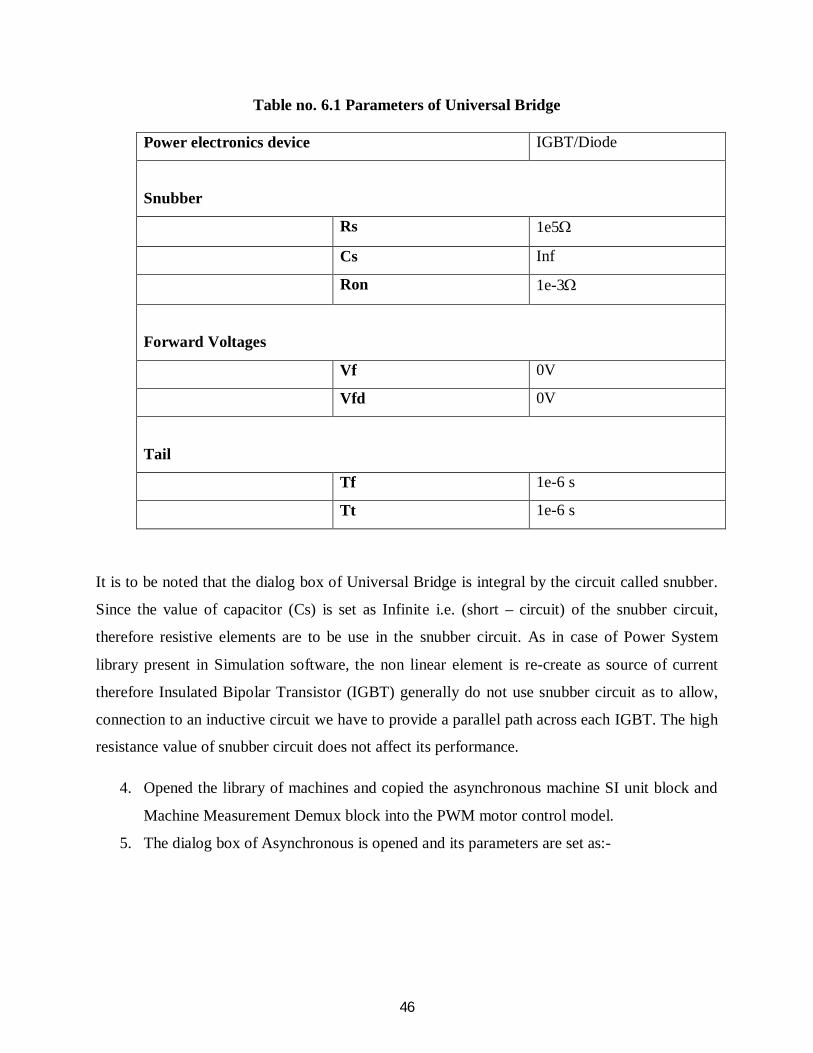
46
Table no. 6.1 Parameters of Universal Bridge Power electronics device IGBT/Diode
Snubber
Rs 1e5
Cs Inf
Ron 1e-3
Forward Voltages
Vf 0V
Vfd 0V
Tail
Tf 1e-6 s
Tt 1e-6 s
It is to be noted that the dialog box of Universal Bridge is integral by the circuit called snubber.
Since the value of capacitor (Cs) is set as Infinite i.e. (short – circuit) of the snubber circuit,
therefore resistive elements are to be use in the snubber circuit. As in case of Power System
library present in Simulation software, the non linear element is re-create as source of current
therefore Insulated Bipolar Transistor (IGBT) generally do not use snubber circuit as to allow,
connection to an inductive circuit we have to provide a parallel path across each IGBT. The high
resistance value of snubber circuit does not affect its performance.
4. Opened the library of machines and copied the asynchronous machine SI unit block and
Machine Measurement Demux block into the PWM motor control model.
5. The dialog box of Asynchronous is opened and its parameters are set as:-

47
Table no. 6.2 Parameters of Asynchronous Machine
Nominal power, voltage (line-line) and
frequency
[3×746, 220, 60]
Stator resistance and Inductance
[1.115 0.005974]
Rotor resistance and Inductance
[1.083 0.005974]
Mutual inductance
0.2037
Inertia constant, friction factor and pole
pairs
[0.02, 0.005752, 2]
The above parameter is about asynchronous machine of 3 HP of two pole pair with the supply
frequency of 60 Hz also nominal power of 3×746 VA with line to line nominal voltage is
220Vrms. From the above data we can calculate the synchronous speed i.e. 1800 rpm which is
slightly greater than nominal speed.
6. The parameter of asynchronous machine is basically set as squirrel cage of rotor type. As
during the normal condition of operation there would be a case of short circuited in
terminals therefore the terminals a, b and c are not accessible.
7. The block of Machine Measurement Demux is opened. As it allows to access specific
interval signal of machine so this block is connected as output of the machine
measurement. First of all machine type of asynchronous is selected and rest all the signals
are deselected:- is_abc (three stator current), Te (electromagnetic torque) and wm (rotor
speed).
6.3.2 Loading and Driving the motors
We have implemented the characteristics of torque speed of motor load. Let the torque speed
characteristics be quadratic, for example – fan or pump type load.

48
As we know that :-
T = k × w2
Where the torque is represents by (T) and speed is represent by (w).
Also the torque is proportional to the square of speed.
Since we have nominal power = 3×746
Synchronous speed = 188.5
= 3×746/188.5
= 11.87 Nm
Or constant k from above equation
K = T/w2
=11.87/188.5
= 3.34 × 10⁻⁴
1. The library of user defined function of simulinks is opened and the block Fcn is copied
into the PWM motor control model. The block menu opened and expression of torque
and entered the function of speed 3.34e – 4*u^2.
2. The input of the Fcn block must be connected to the speed output of Machine
Measurement Demux block which labeled wm and its output of the torque input of the
motor which labeled Tm.
3. The Electrical source library opened and DC Voltage source must be copied into their
model PWM Motor Control. The block menu is opened and voltage is set to 400 V.
4. The measurement library is opened and Voltage Measurement Block copied into PWM
Motor Control model
5. From the element library of simulinks, the ground blocks are copied and completed the
requirement for power elements and the interconnection of Voltage Sensor.

49
6.3.3 With Pulse Generator Controlling of Inverter Bridge
A pulse generator is required for controlling bridge inverter and such elements are available extra
library of power library.
1. The block of Discrete/Extra is opened and three-phase discrete pulse width modulation
Generator is copied in PWM motor control model. The pulses are generated for two level
or three phase bridge by this block. Two level of single bridge pulse width modulation
generator used by generated two set of pulse by this block. Internally three pulse width
modulating signals are generated as the converter operates in an open loop. The output
pulse P1 is connected to the input block of the universal bridge.
2. The block of discrete 3-phase pulse width modulation generator is opened and its
parameter are as :-
Table no. 6.3 Parameters of Discrete Three Phase PWM Generator Type
2 level
Mode of Operation
Un – synchronized
Carrier Frequency
18×60 Hz (1080 Hz)
Internal generation of modulating signals
Selected
Modulation index m
0.9
Output voltage frequency
60 Hz
Output voltage phase
0 degrees
Sample time
10e – 6 s
1. To see how the PWM implemented, the further steps are as follows:-
Diagram>Mask>Look under Mask menu item. The entire simulink blocks are used to
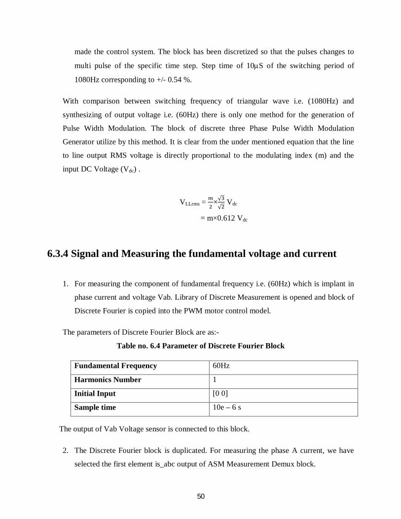
50
made the control system. The block has been discretized so that the pulses changes to
multi pulse of the specific time step. Step time of 10S of the switching period of
1080Hz corresponding to +/- 0.54 %.
With comparison between switching frequency of triangular wave i.e. (1080Hz) and
synthesizing of output voltage i.e. (60Hz) there is only one method for the generation of
Pulse Width Modulation. The block of discrete three Phase Pulse Width Modulation
Generator utilize by this method. It is clear from the under mentioned equation that the line
to line output RMS voltage is directly proportional to the modulating index (m) and the
input DC Voltage (Vdc) .
VLLrms = ×√√
Vdc
= m×0.612 Vdc
6.3.4 Signal and Measuring the fundamental voltage and current
1. For measuring the component of fundamental frequency i.e. (60Hz) which is implant in
phase current and voltage Vab. Library of Discrete Measurement is opened and block of
Discrete Fourier is copied into the PWM motor control model.
The parameters of Discrete Fourier Block are as:-
Table no. 6.4 Parameter of Discrete Fourier Block
Fundamental Frequency 60Hz
Harmonics Number 1
Initial Input [0 0]
Sample time 10e – 6 s
The output of Vab Voltage sensor is connected to this block.
2. The Discrete Fourier block is duplicated. For measuring the phase A current, we have
selected the first element is_abc output of ASM Measurement Demux block.

51
From the simulink Signal Routing library a selector block is being copied. Its menu is
opened and set Index vector (dialog). The output of selector is connected to second
Fourier Discrete block and its input to the is_abc output of the Machine Measurement
Demux block.
3. At last scope is being added to the model. One scope is being duplicated into the model
circuit. All four parameters i.e. motor current, voltage, speed and electromagnetic torque
is basically exhibit by using scope.
Parameters of Scope are as:-
Table no. 6.5 Parameters of Scope Block
Number of axes 4
Time range 0.05 s
Tick labels Bottom axis only
As from the result of TCR simulation the above inputs (4 inputs) are being joined and marked.
At the time of simulation these marked are highlighted on the top of each graph.
The parameters of scope present in Scope Properties >Data History is set as:
Table no. 6.6 Parameters of Data History in Scope Properties
Limit data point to last Deselected
Save data to workshop Selected
Variable name ASM
Format Structure with time
After the simulation, the above 4 signals are exhibits in a structural type array called ASM.
4. From the four input scope it is being replicated into two input scope. The fundamental
components of Vab voltage and Ia current is being displayed by this scope. The input of
scope is being connected to output of Fourier blocks. As shown in the result of TCR it is
being described that the two connections is being marked.
52
And the simulation of the starting motor is ready.
6.3.5 Simulation With continuous integration algorithm of PWM
Motor Drive The dialog box of Simulation>Configuration parameter is opened. In this following steps ode
23tb integration algorithm is selected. The relative tolerance is set as 1e – 4, the Max step size
and the absolute tolerance is set to auto and the stop time to set as 1 s. After that the simulation is
started.
A speed of steady state is 181rad/s i.e.1728rpm is gained by the motor after 0.5s is being started.
Normally the magnitude of 60Hz and current to 90A where as at the time of starting the steady
state value is 10.5A. As it is noticed that the magnitudes of fundamental frequency of 60 Hz hold
in the by parts wave which given as:-
220×√2 = 311V
Likewise at the starting time, it is expected to have strong oscillation of electromagnetic torque.
If we zoomed on the torque in the steady state, we would observe a noisy signal with a mean
value of 11.9 Nm which corresponding to the load torque. Since the component of fundamental
frequency of 60Hz is superior, in case of motor current we could see all harmonics are filter out
from inductance of stator.
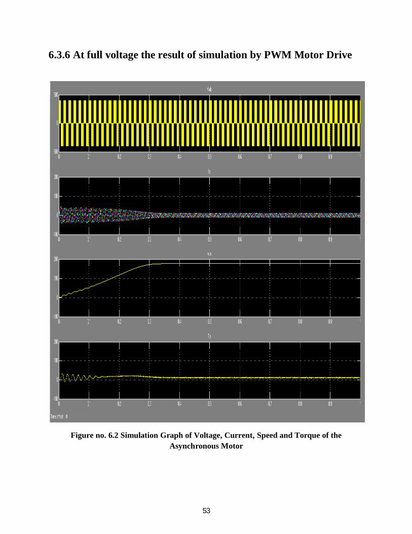
53
6.3.6 At full voltage the result of simulation by PWM Motor Drive
Figure no. 6.2 Simulation Graph of Voltage, Current, Speed and Torque of the
Asynchronous Motor

54
6.3.7 Using the Multimeter Block
With the presence of all six the individual switches are accessible the Universal Bridge basically
not a customary type of subsystem. A multimeter block is used to measure switching current and
voltage as it also provide gain for the internal signals of bridge.
1. The dialog box of universal bridge is opened and device current set as measurement
parameter.
2. A block of multimeter is copied from the measurement library into the PWM motor
model. By double click on the multimeter block, a new window is opened which tends
to show six switch currents.
3. Two currents are selected of the bridge arm connected to phase A. They are identified
as:-
Table no. 6.7 Switch Currents of multimeter iSw1 Universal Bridge
iSw2 Universal Bridge
4. Clicked on closed option of the no. of signal two in the icon of multimeter is being
displayed.
5. By using a Demux Block the two output signals of multimeter is inputted into the scope.
6. The simulation is restarted. For first 20 ms the waveform obtained are shown in this
plot.

55
Figure no. 6.3 Simulation Graph of multimeter switches
As noticed from switches 1 and 2 the switching current is antonymous to each other. The current
flowing through IGBT points the positive current, whereas current through anti parallel diode
points the negative current.
It is noted that the use of multi meter is not restrict to the block called universal bridge. The
presence of numerous blocks in the libraries of Electrical Source and Measurement has
parameter for measurement where we can select voltages, currents or saturable transformer
fluxes. The use of multimeter block is also used to reduce current and voltage sensor into the
model which makes it easier to follow.
6.3.8 Discretize Pulse Width Modulation of Motor Drive
It is noted that in the simulation it is comparatively long in the use of algorithm of variable step
integration one. For simulating 1 sec it may take 10 sec. Thus simulation can be done at fixed
step of time to less the time period of simulation.
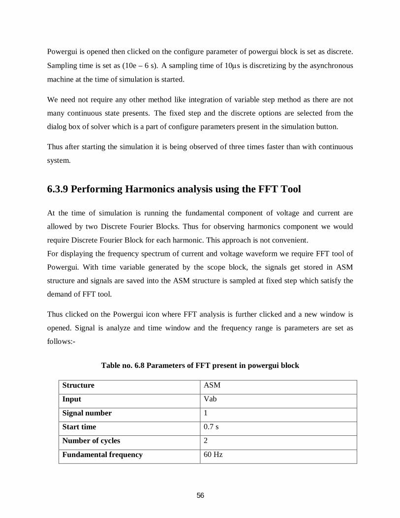
56
Powergui is opened then clicked on the configure parameter of powergui block is set as discrete.
Sampling time is set as (10e – 6 s). A sampling time of 10s is discretizing by the asynchronous
machine at the time of simulation is started.
We need not require any other method like integration of variable step method as there are not
many continuous state presents. The fixed step and the discrete options are selected from the
dialog box of solver which is a part of configure parameters present in the simulation button.
Thus after starting the simulation it is being observed of three times faster than with continuous
system.
6.3.9 Performing Harmonics analysis using the FFT Tool
At the time of simulation is running the fundamental component of voltage and current are
allowed by two Discrete Fourier Blocks. Thus for observing harmonics component we would
require Discrete Fourier Block for each harmonic. This approach is not convenient.
For displaying the frequency spectrum of current and voltage waveform we require FFT tool of
Powergui. With time variable generated by the scope block, the signals get stored in ASM
structure and signals are saved into the ASM structure is sampled at fixed step which satisfy the
demand of FFT tool.
Thus clicked on the Powergui icon where FFT analysis is further clicked and a new window is
opened. Signal is analyze and time window and the frequency range is parameters are set as
follows:-
Table no. 6.8 Parameters of FFT present in powergui block
Structure ASM
Input Vab
Signal number 1
Start time 0.7 s
Number of cycles 2
Fundamental frequency 60 Hz

57
Max frequency 5000Hz
Frequency axis Harmonic order
Display style Bar (relative to Fund or DC)
As Display option clicked the analysis of the signal is shown and spectrum of frequency is being
shown at the bottom of this window.
6.3.10 Analysis of Line to Line Voltage of Motor by Fast Fourier Transformation
Figure no. 6.4 FFT analysis of the Asynchronous motor
As the fundamental complement and the Total Harmonics Distortion of Vab is shown in the new
window and the value of fundamental of inverter voltage is (312V) which comparatively more
than the predefined value i.e. (311V for m=0.4).
As given from the multiple carrier frequency which is given as in general formula (n×18+k) the
harmonics are shown in the percentage value of the fundamentally component.
For new spectrum of current is being displayed, change the inputted selected from Vab to Ia.

58
6.4 Results
The simulation result of fundamental speed is being calculated from a 4 pole Asynchronous
motor of 3 HP and also the analysis of harmonics being calculated by using FFT tool of
simulation of maximum frequency 5000 Hz.
Table no. 6.9 Data analysis of Frequency
Frequency (f) RPM (Ns) THD of Voltage THD of Current
80 2400 106.25% 30.49%
75 2250 81.86% 19.65%
70 2100 67.89% 14.91%
65 1950 55.46% 12.20%
60 1800 78.59% 11.46%
55 1650 55.85% 18.72%
50 1500 76.85% 32.86%
45 1350 126.29% 37.35%
Thus from the analysis of table no.10 it is clear that the frequency variation leads to the
harmonics change in the machine also as the speed decreases or increases beyond the nominal
point of range in frequencies, the Total Harmonics Distortion in voltage as well as in current
increases also the THD in voltage is higher than THD in current. It is also to be noted that too
much variation in frequency also leads to increase in the THD voltage as well as THD current
levels. Thus the THD (V) level increases with as the value of fundamental frequency increases
from 70Hz and also the fundamental frequency decreases 45 Hz or below. Therefore the range of
variations of fundamental frequency should be kept in between 70 to 45 Hz. It is also to be
noticed that the values of THD (V) in case of 70Hz, 60Hz and 45Hz is quit high as compared to

59
other frequency presents in between them, this is because of presence of ODD Harmonics in
these frequencies, as we know that the ODD harmonics are more harmful for the promotion of
Distortion in the circuit than the EVEN Harmonics. Since the maximum frequency is set as
5000Hz therefore it can be easily calculated the order of Harmonics. The calculation of ODD
Harmonics and EVEN Harmonics is given in table no.11
Table No. 6.10 Calculation of order of Harmonics
Fundamental
Frequency
Speed (RPM) Order of
Harmonics
THD of Voltage THD of Current
80 2400 62.5(even) 106.25% 30.49%
75 2250 66.66(even) 81.86% 19.65%
70 2100 71.42(odd) 67.89% 14.91%
65 1950 76.92(even) 55.46% 12.20%
60 1800 83.33(odd) 78.59% 11.46%
55 1650 90.90(even) 55.85% 18.72%
50 1500 100(even) 76.85% 32.86%
45 1350 111.11(odd) 126.29% 37.35%
Thus the variation of THD in between the fundamental frequencies is keep changing therefore
there are variation for distortion which leads to the calculation of energy savings is quite possible
as well as speed control of the motor.
These harmonics can be further reduced by the applications of filters in the circuit. As earlier
discussed in section 4.8 i.e. the Harmonics Mitigation Techniques where various types of
techniques are explained which help in filtering the harmonics. It could be act as a future
reference of this dissertation report.

60
CHAPTER 7
CONCLUSION AND FUTURE WORK
After the detailed study of Variable Frequency Drive, it becomes possible to control the speed of
electric motor as well as to conserve the electrical energy, as we know that the energy
conservation has become an important subject to all over the world. Increase in efficient energy
use, decrease in energy consumption and/or consumption from conventional energy sources is
reduced that leads to the conservation of energy.
For high performance providing by the Variable Frequency Drive for maximum process
productivity always required a complex engineering consideration. However rapid improvements
in AC control technology combined with ready availability of standard fixed frequency of AC
motor have increased the number of possible solution. With the process of pulse width
modulation, the frequency given to the induction motor can be set in order to control the speed of
the induction motor. Thus the consumption of electrical energy is depends on the load
requirement. However the variation of frequency leads to the harmonics distortion which can be
mitigate by several techniques of harmonics mitigation.
The elimination techniques of harmonics are generally applied to lowest harmonic because as the
filtering is more practical at higher harmonics, the filtering component can be smaller and less
expensive. Also application of several multilevel inverters provides another approach to
harmonics cancellation. For the mitigation of harmonics from the circuit of the inverter
application of active filters are required into the circuit such as Band Pass Active Filter.
Basically Band Pass Filter can be applied in this circuit as a future reference of this dissertation.
A Band Pass Filter is a electronic device or circuit that allow to pass signals between two
specific frequencies but discriminates against the signal at other frequencies.

61
Figure No. 7.1 Circuit diagram of Band Pass Filter
At last the conservation of energy may result in increase in financial, capital, environment
quality, national security, personal security and human comfort. The individual and commercial
user can increase energy use efficiency to maximum profit which leads to help for the individual
and organization that are direct consumer of energy security.

62
REFERENCES
Journals
1. Jaehyuck Kim, Keunsoo Ha and R Krishnan, “Single – Controllable – Based Switched
Reluctance Motor Drive For Low Costs, Variable – Speed Applications,” IEEE
Transactions on Power Electronics, vol. 27, no. 1,pp 379 – 387, January 2012.
2. Jigar N. Mistry, Hetal D. Solanki and Tejas M. Vala, “Variable Frequency Drive,”
Research Expo International Multidisciplinary Research Journal (REIMRJ), vol. II, issue
III, ISSN 2250 – 1630, pp 252 – 256, September 2012.
3. Neetha John, Mohandas R and Suja C Rajappan, “Energy Saving Mechanism Using
Variable Frequency Drives,” International Journal of Emerging Technology and
Advanced Engineering (IJETAE), vol. 3, issue 3, pp 784 – 790, March 2013.
4. Micheal A. Berneir and Bernard Bourret, “Pumping Energy and Variable Frequency
Drives,” ASHRAE Journal, pp 37 – 40, December 1999.
Conference Proceedings
5. Aung Zaw Latt and Dr. Ni Ni Win, “Variable Speed Drive of Single Phase Induction
Motor Using Frequency Control Method,” International Conference on Education
Technology and Computer by IEEE Computer Society, DOI:- 10th Nov. 2009, pp 30 – 34.
Books
6. Leonard L. Grigsby, “Power System,” Handbook of Electric Power Engineering, CRC
Press,© Taylor and Francis Group, ISBN- 13:978-0-8493-9288-7.

63
7. Steve Doty and Wayne C Turner, “Handbook of Energy Management,”© 2009 The
Farimont Press, Inc. ,printed in The United States Of America, ISBN- 10:0-88173-609-0.
8. Michael F. Hordeski, “New Technology for Energy Efficiencies,”© 2003The Fairmont
Press, INC. Liiburn, Georgia, ISBN: 0-203-91174-1.
9. Mukund R. Patel, “Introduction to Electrical Power and Power Electronics,” CRC Press,
© 2013 by Taylor and Francis group, ISBN: 978-1-4665-5660-7.
10. Ross Montogomery and Robert Mcdowall, “Fundamental of HVAC Control System,” A
Course Reader Book ASHRAE Learning Institute, ©2009 American Society of Heating,
Refrigeration and Air – Conditioning Engineers, Inc., ISBN: 978-0-08-055234-7.
11. Elsevier Advanced Technology, “Variable Speed Pumping,” A Guide to Successful
Application, Copyright © 2004 Hydraulic institute and Europump, ISBN:1-85617-449-2.
12. Robert S. Carrow, “Variable Frequency Drive,” Electrical Technical Reference,
Copyright© 2001 Delmar – A Division of Thomson Learning Inc., ISBN 0-7668-1923-X,
printed in The United States Of America.
13. Malcolm Barnes, “Practical Variable Speed Drive,” © 2003 IDC Technologies, Printed
and Bound in Great Britain, ISBN: 07506 58088.
14. Richard P. Beverly, “Pump Selection and Trouble Shooting Field,” Copyright © 2009
American Water Works Association, ISBN: 978-1-58321-727-4.
64
Project
15. Omar David Munoz, “Design Strategy for a Three Phase Variable Frequency Drive,”
Senior Project, Electrical Engineering Department, California Polytechnic State
University, San Luis Obispo, 2011.
Website
16. www.mathworks.in (© 1994 – 2013 The Mathworks, Inc.), “Simulate Variable Speed
Motor Control – MATLAB and Simulink – Mathworks India,”
www.mathworks.in/help/physmod/powersys/ug/simulating-variable-speed-motor-
control.html
17. memberfiles.freewebs.com (© 2003 IEEE), “Simulink Implementation of Induction
Machine Model – A Modullar Approach,” by Burak Ozpineci and Leon M. Tolbert
.
18. www.freewebs.com, “Simulation of Half Wave and Full Wave Uncontrolled Rectifier
Circuits,” Belwin_BEEE Lab Manual EE101.
19. www.ece.ualberta.ca (© Andy Knight), “Diode Bridge Simulation,” Variable Speed
Drive : Simulation Example,
www.ece.ualberta.ca/~knight/variable_speed_drives/ssim/config/sim.html
20. http://en.wikipedia.org, “Variable Frequency Drive,”
http://en.wikipedia.org/wiki/Variable-frequency_drive
21. http://www.google.co.in , “ Variable Frequency Drive,”
http://www.google.co.in/search?q=variable%20frequency%20drive